

Page 1

IBM IntelliStation Z Pro Type 9228 and 9232
P roble m Dete rminatio n and
Service Guide
Page 2

Page 3

IBM IntelliStation Z Pro Type 9228 and 9232
P roble m Dete rminatio n and
Service Guide
Page 4

Note:
Before using this information and the product it supports, read the general information in Appendix B, “Notices,” on page 151 and
the Warranty and Support Information documentation on the IBM IntelliStation Documentation CD.
Tenth Edition (August 2009)
© Copyright International Business Machines Corporation 2007.
US Government Users Restricted Rights – Use, duplication or disclosure restricted by GSA ADP Schedule Contract
with IBM Corp.
Page 5

Contents
Safety ............................vii
Guidelines for trained service technicians ...............viii
Inspecting for unsafe conditions .................viii
Guidelines for servicing electrical equipment .............viii
Safety statements ........................ix
Chapter 1. Introduction ......................1
Related documentation ......................1
Notices and statements in this document ................2
Features and specifications .....................3
Controls, LEDs, and connectors ...................4
Front view ..........................4
Rear view ..........................5
Internal LEDs, connectors, and jumpers ................8
System board option connectors ..................8
System board internal connectors .................9
System board external connectors .................10
System board LEDs ......................11
System board jumpers .....................12
Chapter 2. Configuration information and instructions .........13
Updating the firmware ......................13
Configuring the computer .....................13
Starting the Configuration/Setup Utility program ............14
Using the Boot Menu program ..................14
Enabling the Broadcom NetXtreme Gigabit Ethernet Boot Agent ......15
Configuring the Broadcom NetXtreme Gigabit Ethernet controller .....15
LSI Logic Configuration Utility program ...............15
Chapter 3. Parts listing, Type 9228 and 9232 .............19
Replaceable computer components .................20
Keyboards (USB) ........................23
Product recovery CDs ......................25
Power cords ..........................26
Chapter 4. Removing and replacing computer components .......29
Installation guidelines ......................29
System reliability guidelines ...................30
Handling static-sensitive devices .................30
Returning a device or component .................31
Removing and replacing consumable parts and Tier 1 CRUs ........31
Removing the side cover ....................31
Installing the side cover.....................32
Removing the two-piece bezel ..................33
Installing the two-piece bezel ...................35
Removing an adapter .....................36
Installing an adapter ......................37
Removing the hard drive backplate ................39
Installing the hard drive backplate .................40
Removing a DIMM ......................41
Installing a DIMM .......................42
Removing the battery .....................45
Installing the battery ......................45
© Copyright IBM Corp. 2007 iii
Page 6

Removing the internal speaker ..................47
Installing the internal speaker ..................47
Removing and replacing Tier 2 CRUs ................48
Removing and installing internal drives ...............48
Removing the hard disk drive fan .................54
Installing the hard disk drive fan .................55
Removing the rear fan .....................57
Installing the rear fan .....................58
Removing the expansion slot fan .................59
Installing the expansion slot fan..................60
Removing the mini-PCI Express adapter ..............60
Installing the mini-PCI Express adapter ...............62
Removing the power switch/LED assembly .............63
Installing the power switch/LED assembly ..............64
Removing the front card/bracket assembly ..............65
Installing the front card/bracket assembly ..............66
Removing and replacing FRUs ...................67
Removing the front adapter-retention bracket .............67
Installing the front adapter-retention bracket .............68
Removing the rear adapter-retention bracket .............69
Installing the rear adapter-retention bracket .............70
Removing the DIMM fan assembly ................70
Installing the DIMM fan assembly .................73
Removing the microprocessor and fan sink .............75
Installing the microprocessor and fan sink ..............77
Removing the power supply ...................80
Installing the power supply ...................82
Removing the system board ...................84
Installing the system board ...................85
Chapter 5. Diagnostics .....................87
Diagnostic tools ........................87
POST ............................87
POST beep codes ......................87
Error logs ..........................93
POST error codes .......................94
Troubleshooting tables .....................107
CD or DVD drive problems ...................108
Diskette drive problems ....................109
General problems ......................109
Hard disk drive problems ....................110
Intermittent problems .....................110
Keyboard, mouse, or pointing-device problems ............111
Memory problems ......................112
Microprocessor problems ....................112
Monitor or video problems ...................112
Optional-device problems ...................114
Power problems .......................115
Printer problems .......................116
Serial port problems .....................116
Software problems ......................117
USB port problems ......................117
Error LEDs ..........................119
Power-supply LEDs .......................120
Diagnostic programs, messages, and error codes ...........122
Running the diagnostic programs .................122
iv IBM IntelliStation Z Pro Type 9228 and 9232: Problem Determination and Service Guide
Page 7

Diagnostic text messages ...................123
Viewing the test logs .....................124
Diagnostic error codes ....................124
Creating an IBM Enhanced Diagnostics diskette or CD.........132
Using the IBM Enhanced Diagnostics diskette or CD .........133
System board error LEDs ...................134
Emergency recovery-repair diskettes (Windows) ............136
Creating an emergency recovery-repair diskette in Windows .......136
Using the recovery-repair diskette in Windows ............137
Recovering the operating system and preinstalled software ........137
Recovering the operating system .................137
Recovering or installing device drivers ...............138
Updating the BIOS code on the computer ..............139
Recovering from a BIOS update failure ...............139
Interrupt status port register error procedures .............140
ServeRAID error codes .....................142
Erasing a lost or forgotten password (clearing CMOS) ..........145
Solving power problems .....................146
Solving Ethernet controller problems ................146
Solving undetermined problems ..................146
Problem determinations tips....................147
Calling IBM for service .....................148
Appendix A. Getting help and technical assistance ..........149
Before you call ........................149
Using the documentation .....................149
Getting help and information from the World Wide Web .........149
Software service and support ...................150
Hardware service and support ...................150
Appendix B. Notices ......................151
Trademarks..........................152
Important notes ........................152
Product recycling and disposal ..................153
Battery return program .....................154
Electronic emission notices ....................156
Federal Communications Commission (FCC) statement ........156
Industry Canada Class B emission compliance statement ........157
Avis de conformité à la réglementation d’Industrie Canada .......157
European Union EMC Directive conformance statement ........157
Notice for South Korea and translations (MIC) ............157
Japanese Voluntary Control Council for Interference (VCCI) statement 157
Index ............................159
Contents v
Page 8

vi IBM IntelliStation Z Pro Type 9228 and 9232: Problem Determination and Service Guide
Page 9

Safety
Before installing this product, read the Safety Information.
Antes de instalar este produto, leia as Informações de Segurança.
Pred instalací tohoto produktu si prectete prírucku bezpecnostních instrukcí.
Læs sikkerhedsforskrifterne, før du installerer dette produkt.
Lees voordat u dit product installeert eerst de veiligheidsvoorschriften.
Ennen kuin asennat tämän tuotteen, lue turvaohjeet kohdasta Safety Information.
Avant d’installer ce produit, lisez les consignes de sécurité.
Vor der Installation dieses Produkts die Sicherheitshinweise lesen.
Prima di installare questo prodotto, leggere le Informazioni sulla Sicurezza.
Les sikkerhetsinformasjonen (Safety Information) før du installerer dette produktet.
Antes de instalar este produto, leia as Informações sobre Segurança.
Antes de instalar este producto, lea la información de seguridad.
Läs säkerhetsinformationen innan du installerar den här produkten.
© Copyright IBM Corp. 2007 vii
Page 10

Guidelines for trained service technicians
This section contains information for trained service technicians.
Inspecting for unsafe conditions
Use the information in this section to help you identify potential unsafe conditions in
an IBM product that you are working on. Each IBM product, as it was designed and
manufactured, has required safety items to protect users and service technicians
from injury. The information in this section addresses only those items. Use good
judgment to identify potential unsafe conditions that might be caused by non-IBM
alterations or attachment of non-IBM features or options that are not addressed in
this section. If you identify an unsafe condition, you must determine how serious the
hazard is and whether you must correct the problem before you work on the
product.
Consider the following conditions and the safety hazards that they present:
v Electrical hazards, especially primary power. Primary voltage on the frame can
cause serious or fatal electrical shock.
v Explosive hazards, such as a damaged CRT face or a bulging capacitor.
v Mechanical hazards, such as loose or missing hardware.
To inspect the product for potential unsafe conditions, complete the following steps:
1. Make sure that the power is off and the power cord is disconnected.
2. Make sure that the exterior cover is not damaged, loose, or broken, and
observe any sharp edges.
3. Check the power cord:
v Make sure that the third-wire ground connector is in good condition. Use a
meter to measure third-wire ground continuity for 0.1 ohm or less between
the external ground pin and the frame ground.
v Make sure that the power cord is the correct type, as specified in “Power
cords” on page 26.
v Make sure that the insulation is not frayed or worn.
4. Remove the cover.
5. Check for any obvious non-IBM alterations. Use good judgment as to the safety
of any non-IBM alterations.
6. Check inside the computer for any obvious unsafe conditions, such as metal
filings, contamination, water or other liquid, or signs of fire or smoke damage.
7. Check for worn, frayed, or pinched cables.
8. Make sure that the power-supply cover fasteners (screws or rivets) have not
been removed or tampered with.
Guidelines for servicing electrical equipment
Observe the following guidelines when servicing electrical equipment:
v Check the area for electrical hazards such as moist floors, nongrounded power
extension cords, and missing safety grounds.
v Use only approved tools and test equipment. Some hand tools have handles that
are covered with a soft material that does not provide insulation from live
electrical current.
v Regularly inspect and maintain your electrical hand tools for safe operational
condition. Do not use worn or broken tools or testers.
viii IBM IntelliStation Z Pro Type 9228 and 9232: Problem Determination and Service Guide
Page 11

v Do not touch the reflective surface of a dental mirror to a live electrical circuit.
The surface is conductive and can cause personal injury or equipment damage if
it touches a live electrical circuit.
v Some rubber floor mats contain small conductive fibers to decrease electrostatic
discharge. Do not use this type of mat to protect yourself from electrical shock.
v Do not work alone under hazardous conditions or near equipment that has
hazardous voltages.
v Locate the emergency power-off (EPO) switch, disconnecting switch, or electrical
outlet so that you can turn off the power quickly in the event of an electrical
accident.
v Disconnect all power before you perform a mechanical inspection, work near
power supplies, or remove or install main units.
v Before you work on the equipment, disconnect the power cord. If you cannot
disconnect the power cord, have the customer power-off the wall box that
supplies power to the equipment and lock the wall box in the off position.
v Never assume that power has been disconnected from a circuit. Check it to
make sure that it has been disconnected.
v If you have to work on equipment that has exposed electrical circuits, observe
the following precautions:
– Make sure that another person who is familiar with the power-off controls is
near you and is available to turn off the power if necessary.
– When you are working with powered-on electrical equipment, use only one
hand. Keep the other hand in your pocket or behind your back to avoid
creating a complete circuit that could cause an electrical shock.
– When using a tester, set the controls correctly and use the approved probe
leads and accessories for that tester.
– Stand on a suitable rubber mat to insulate you from grounds such as metal
floor strips and equipment frames.
v Use extreme care when measuring high voltages.
v To ensure proper grounding of components such as power supplies, pumps,
blowers, fans, and motor generators, do not service these components outside of
their normal operating locations.
v If an electrical accident occurs, use caution, turn off the power, and send another
person to get medical aid.
Safety statements
Safety ix
Page 12

Important: Each caution and danger statement in this documentation begins with a
number. This number is used to cross reference an English-language caution or
danger statement with translated versions of the caution or danger statement in the
IBM Safety Information document.
For example, if a caution statement begins with a number 1, translations for that
caution statement appear in the IBM Safety Information document under statement
1.
Be sure to read all caution and danger statements in this documentation before
performing the instructions. Read any additional safety information that comes with
your computer or optional device before you install the device.
x IBM IntelliStation Z Pro Type 9228 and 9232: Problem Determination and Service Guide
Page 13

Statement 1:
DANGER
Electrical current from power, telephone, and communication cables is
hazardous.
To avoid a shock hazard:
v Do not connect or disconnect any cables or perform installation,
maintenance, or reconfiguration of this product during an electrical
storm.
v Connect all power cords to a properly wired and grounded electrical
outlet.
v Connect to properly wired outlets any equipment that will be attached to
this product.
v When possible, use one hand only to connect or disconnect signal
cables.
v Never turn on any equipment when there is evidence of fire, water, or
structural damage.
v Disconnect the attached power cords, telecommunications systems,
networks, and modems before you open the device covers, unless
instructed otherwise in the installation and configuration procedures.
v Connect and disconnect cables as described in the following table when
installing, moving, or opening covers on this product or attached
devices.
To Connect: To Disconnect:
1. Turn everything OFF.
2. First, attach all cables to devices.
3. Attach signal cables to connectors.
4. Attach power cords to outlet.
5. Turn device ON.
1. Turn everything OFF.
2. First, remove power cords from outlet.
3. Remove signal cables from connectors.
4. Remove all cables from devices.
Safety xi
Page 14

Statement 2:
CAUTION:
When replacing the lithium battery, use only IBM Part Number 33F8354 or an
equivalent type battery recommended by the manufacturer. If your system has
a module containing a lithium battery, replace it only with the same module
type made by the same manufacturer. The battery contains lithium and can
explode if not properly used, handled, or disposed of.
Do not:
v Throw or immerse into water
v Heat to more than 100°C (212°F)
v Repair or disassemble
Dispose of the battery as required by local ordinances or regulations.
Statement 3:
CAUTION:
When laser products (such as CD-ROMs, DVD drives, fiber optic devices, or
transmitters) are installed, note the following:
v Do not remove the covers. Removing the covers of the laser product could
result in exposure to hazardous laser radiation. There are no serviceable
parts inside the device.
v Use of controls or adjustments or performance of procedures other than
those specified herein might result in hazardous radiation exposure.
DANGER
Some laser products contain an embedded Class 3A or Class 3B laser
diode. Note the following.
Laser radiation when open. Do not stare into the beam, do not view directly
with optical instruments, and avoid direct exposure to the beam.
xii IBM IntelliStation Z Pro Type 9228 and 9232: Problem Determination and Service Guide
Page 15

Statement 4:
≥ 18 kg (39.7 lb) ≥ 32 kg (70.5 lb) ≥ 55 kg (121.2 lb)
CAUTION:
Use safe practices when lifting.
Statement 5:
CAUTION:
The power control button on the device and the power switch on the power
supply do not turn off the electrical current supplied to the device. The device
also might have more than one power cord. To remove all electrical current
from the device, ensure that all power cords are disconnected from the power
source.
2
1
Safety xiii
Page 16

Statement 8:
CAUTION:
Never remove the cover on a power supply or any part that has the following
label attached.
Hazardous voltage, current, and energy levels are present inside any
component that has this label attached. There are no serviceable parts inside
these components. If you suspect a problem with one of these parts, contact
a service technician.
Statement 26:
CAUTION:
Do not place any object on top of rack-mounted devices.
Statement 27:
CAUTION:
Hazardous moving parts are nearby.
Statement 28:
xiv IBM IntelliStation Z Pro Type 9228 and 9232: Problem Determination and Service Guide
Page 17

CAUTION:
The battery is a lithium ion battery. To avoid possible explosion, do not burn
the battery. Exchange it only with the IBM-approved part. Recycle or discard
the battery as instructed by local regulations. In the United States, IBM has a
process for collection of this battery. For information, call 1-800-426-4333.
Have the IBM part number for the battery unit available when you call.
Important:
This computer is suitable for use on an IT power distribution system whose
maximum phase to phase voltage is 240 V under any distribution fault condition.
Safety xv
Page 18

xvi IBM IntelliStation Z Pro Type 9228 and 9232: Problem Determination and Service Guide
Page 19

Chapter 1. Introduction
This Problem Determination and Service Guide contains information to help you
solve problems that might occur in your IBM
9232 computers. It describes the diagnostic tools that come with the computer, error
codes and suggested actions, and instructions for replacing failing components.
Replaceable components are of four types:
v Consumable parts: Purchase and replacement of consumable parts
(components, such as batteries and printer cartridges, that have depletable life)
is your responsibility. If IBM acquires or installs a consumable part at your
request, you will be charged for the service.
v Tier 1 customer replaceable unit (CRU): Replacement of Tier 1 CRUs is your
responsibility. If IBM installs a Tier 1 CRU at your request, you will be charged for
the installation.
v Tier 2 customer replaceable unit: You may install a Tier 2 CRU yourself or
request IBM to install it, at no additional charge, under the type of warranty
service that is designated for your server.
v Field replaceable unit (FRU): FRUs must be installed only by trained service
technicians.
For information about the terms of the warranty and getting service and assistance,
see the Warranty and Support Information document on the IBM IntelliStation
Documentation CD.
®
IntelliStation®Z Pro Type 9228 and
Related documentation
In addition to this document, the following documentation also comes with the
computer:
v Installation Guide
This printed document contains instructions for setting up the computer. This
document is also in Portable Document Format (PDF) on the IBM IntelliStation
Documentation CD.
v User’s Guide
This document is in PDF on the IBM IntelliStation Documentation CD. It contains
general information about the computer, including information about features, and
how to configure the computer. It also contains detailed instructions for installing,
removing, and connecting optional devices that the computer supports.
v Safety Information
This document is in PDF on the IBM IntelliStation Documentation CD. It contains
translated caution and danger statements. Each caution and danger statement
that appears in the documentation has a number that you can use to locate the
corresponding statement in your language in the Safety Information document.
v Warranty and Support Information
This document is in PDF on the IBM IntelliStation Documentation CD. It contains
information about the terms of the warranty and getting service and assistance.
© Copyright IBM Corp. 2007 1
Page 20

v Readme files on the Device Drivers CD
Several readme files on this CD contain information about the preinstalled device
drivers. Other readme files on this CD contain information about the various
adapters and devices that might be installed in or attached to the computer.
v IBM IntelliStation Documentation CD
This CD contains all of the IBM IntelliStation Z Pro Type 9228 and 9232
documents in Portable Document Format (PDF).
Depending on the computer model, additional documentation might be included on
the IBM IntelliStation Documentation CD.
The computer might have features that are not described in the documentation that
comes with the computer. The documentation might be updated occasionally to
include information about those features, or technical updates might be available to
provide additional information that is not included in the server documentation.
These updates are available from the IBM Web site. To check for updated
documentation and technical updates, complete the following steps.
Note: Changes are made periodically to the IBM Web site. The actual procedure
might vary slightly from what is described in this document.
1. Go to http://www.ibm.com/support/.
2. Under the Search technical support section, type 9228 or 9232, and click
Search.
Notices and statements in this document
The caution and danger statements that appear in this document are also in the
multilingual Safety Information document, which is on the IBM IntelliStation
Documentation CD. Each statement is numbered for reference to the corresponding
statement in the Safety Information document.
The following notices and statements are used in this document:
v Note: These notices provide important tips, guidance, or advice.
v Important: These notices provide information or advice that might help you avoid
inconvenient or problem situations.
v Attention: These notices indicate potential damage to programs, devices, or
data. An attention notice is placed just before the instruction or situation in which
damage could occur.
v Caution: These statements indicate situations that can be potentially hazardous
to you. A caution statement is placed just before the description of a potentially
hazardous procedure step or situation.
v Danger: These statements indicate situations that can be potentially lethal or
extremely hazardous to you. A danger statement is placed just before the
description of a potentially lethal or extremely hazardous procedure step or
situation.
2 IBM IntelliStation Z Pro Type 9228 and 9232: Problem Determination and Service Guide
Page 21

Features and specifications
The following table provides a summary of the features and specifications of the
computer. Depending on the model, some features might not be available, or some
specifications might not apply.
Use the Configuration/Setup Utility program to determine the type and speed of the
microprocessor.
Table 1. Features and specifications
Microprocessor:
v Supports up to two Intel
dual-core microprocessors
v One 4 MB Level-2 cache
v 1333 MHz front-side bus (FSB)
Memory:
v Minimum: 1 GB
v Maximum: 32 GB (mirroring mode 16
GB)
v Type: PC2-5300, 667 MHz,
dual-data-rate 2 (DDR2)
fully-buffered error correcting code
(ECC)
v Connectors: eight dual inline memory
module (DIMM) connectors
Internal drives:
v Hard disk drive: SATA or SAS
v One of the following drives:
– DVD/CD-RW combo: IDE
– CD-RW: IDE
– CD-ROM: IDE
– DVD ROM: IDE
– Multi-burner Plus: IDE
Expansion bays:
v Two half-high 5.25-inch bays (optical
drive installed in one bay)
v Four slim-high 3.5-inch internal drive
bays (one hard disk drive installed)
v One slim-high 3.5-inch drive bay
(optional diskette drive)
PCI expansion slots:
v One PCI Express x16 (x16) slot
v One PCI Express x16 (x4) slot
v One PCI Express x8 (x4) slot
v One PCI 32-bit/33 MHz slot
v Two PCI-X 64-bit 133 MHz slots
Power supply:
v One 815-watt power supply
®
Xeon
Integrated functions:
v Broadcom BC5752KFB 10/100/1000
Ethernet controller with RJ-45 Ethernet
connector
v One serial connector
v Four-port Serial ATA controller
v Two IEEE 1394A (FireWire) ports (one
on rear, one on front)
v Seven Universal Serial Bus (USB)
connectors (two on front, four on rear,
and one internal)
v Keyboard connector
v Mouse connector
v Audio connectors
– Line out (rear)
– Mic (front and rear)
– Line in (rear)
– Headphone (front)
v Single-channel IDE controller
Video adapter (depending on the model):
v NVIDIA Quadro NVS 285 (DMS-59),
PCI Express x16, with 128 MB DDR2
SDRAM and dual analog connectors,
(or dual digital monitor capability with
the purchase of an additional pigtail
cable)
v NVIDIA Quadro FX 550 (DVI-I), PCI
Express x16, with 128 MB GDDR3
synchronous dynamic random access
memory (SDRAM) and dual DVI-I
connectors
v NVIDIA Quadro FX 1500 (dual-link
DVI-I), PCI Express x16, with 256 MB
GDDR3 SDRAM and two dual DVI-I
connectors
v NVIDIA Quadro FX 3500 (DVI-I), PCI
Express x16, with 256 MB GDDR3
SDRAM and two dual DVI-I connectors
v NVIDIA Quadro FX 4500 (DVI-I), PCI
Express x16, with 512 MB GDDR3
SDRAM and two dual DVI-I connectors
Electrical input:
v Sine-wave input (50 or 60 Hz) required
v Input voltage and frequency ranges
automatically selected
v Input voltage low range:
– Minimum: 100 V ac
– Maximum: 124 V ac
v Input voltage high range:
– Minimum: 200 V ac
– Maximum: 240 V ac
v Input kilovolt-amperes (kVA) approximately:
– Minimum: 0.03 kVA
– Maximum: 1.24 kVA
Heat output:
Approximate heat output in British thermal
units (Btu) per hour:
v Minimum configuration: 870 Btu per hour
(255 watts)
v Maximum configuration: 3495 Btu per hour
(1025 watts)
Environment:
v Air temperature:
– Computer on: 10° to 35°C (50° to 95°F)
Altitude: 0 to 2134 m (7000 ft)
– Computer off: -40° to +60°C (-40° to
+140°F)
Maximum altitude: 2133 m (7000 ft)
v Humidity (operating and storage): 8% to
80%
Acoustical noise emissions:
v Sound power, idle: 4.3 bel (with SATA hard
disk drive)
v Sound power, operating: 5.3 bel
Size:
v Height: 467.3 mm (18.4 in.)
v Depth: 492.7 mm (19.4 in.)
v Width: 215.9 mm (8.5 in.)
v Weight: 18.1 kg (40 lb) to 21.8 kg (48 lb)
depending upon configuration
Cooling:
v Six to eight speed-controlled fans
and one power-supply fan
Chapter 1. Introduction
3
Page 22
Controls, LEDs, and connectors
This section describes the computer controls, light-emitting diodes (LEDs), and
connectors.
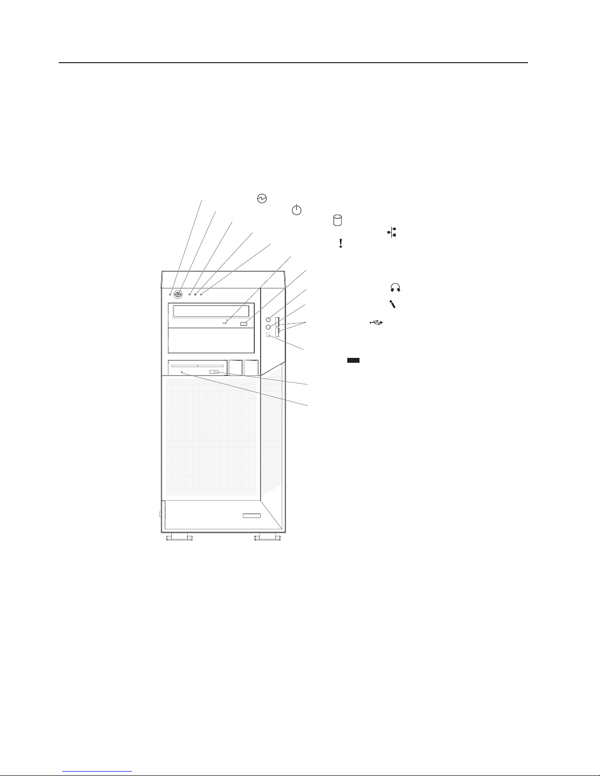
Front view
Figure 1 shows the controls, LEDs, and front connectors on the IntelliStation Z Pro
Type 9228 and 9232 computers. See the User’s Guide for an illustration and
description of the input/output connectors on the rear of the computer.
Power-on LED
Power-control button
Hard disk drive activity LED
Ethernet transmit/receive activity LED
System-error LED
CD or DVD drive activity LED
CD or DVD eject button
Headphone connector
Microphone connector
USB connectors
Figure 1. Controls, LEDs, and indicators
Power-on LED
When this LED is lit, it indicates that the computer is turned on.
Power-control button
Press this button to turn the computer on or off.
IEEE 1394A (FireWire)
connector
Optional disketteeject button
Optional diskette
drive activity LED
1394
Hard disk drive activity LED
When this LED is lit, it indicates that the hard disk drive is in use.
Ethernet transmit/receive activity LED
When this LED is lit, it indicates that there is activity between the computer
and the network. There are two of these LEDs, one on the front and one on
the rear of the computer.
4 IBM IntelliStation Z Pro Type 9228 and 9232: Problem Determination and Service Guide
Page 23

System-error LED
When this LED is lit, it indicates that a system error has occurred. An LED
on the system board might also be lit to help isolate the error. If the LED on
the system board is not lit, check the error log.
CD or DVD drive activity LED
When this LED is lit, it indicates that the CD or DVD drive is in use.
CD or DVD eject button
Press this button to insert a CD or DVD into or remove a CD or DVD from
the CD or DVD drive.
Headphone connector (green)
Use this connector to send audio signals from the computer to external
devices, such as speakers with built-in amplifiers, headphones, multimedia
keyboards, or the audio line-in jack on a stereo system.
Microphone connector (pink)
Use this connector to connect a microphone to the computer when you
want to record voices or other sounds on the hard disk. You can also use
this connector (and a microphone) with speech-recognition software.
USB connectors
Use these connectors to connect USB devices to the computer, using
redundant Plug and Play technology.
IEEE 1394A (FireWire) connectors
Use these connectors (four-pin on the front and six-pin on the rear) to
connect FireWire devices, such as digital video cameras and external hard
disk drives.
Rear view
Optional diskette-eject button
Press this button to release a diskette from the diskette drive.
Optional diskette drive activity LED
When this LED is lit, it indicates that the diskette drive is in use.
The following illustration shows the connectors and indicators on the rear of the
computer.
Chapter 1. Introduction 5
Page 24

Mouse connector
Connect a mouse device to this connector.
Keyboard connector
Connect a keyboard to this connector.
Serial connector
Connect a 9-pin serial device to this connector.
USB 3 and 4 connectors
Connect USB devices to these connectors.
IEEE 1394A (FireWire) connector
Use this connector (six-pin on the rear) to connect FireWire devices, such
as digital video cameras and external hard disk drives.
USB 5 and 6 connectors
Connect USB devices to these connectors.
Ethernet connector
Use this connector to connect the computer to a network.
Microphone connector (pink)
Use this connector to connect a microphone to the computer when you
want to record voices or other sounds on the hard disk drive. You can also
use this connector (and a microphone) with speech-recognition software.
Line out connector (green)
Connect an audio output device, such as speakers, to this connector.
Line in connector (blue)
Connect an audio input device, such as stereo, to this connector.
Video connector
Connect a monitor to this connector.
6 IBM IntelliStation Z Pro Type 9228 and 9232: Problem Determination and Service Guide
Page 25

DC power LED
On some computer models, each power supply has a dc power LED and
an ac power LED. During typical operation, both the ac and dc power LEDs
are lit.
AC power LED
On some computer models, each power supply has an ac power LED and
a dc power LED. During typical operation, both the ac and dc power LEDs
are lit.
Power-cord connector
Connect the power cord to this connector.
Chapter 1. Introduction 7
Page 26

Internal LEDs, connectors, and jumpers
The illustrations in this section show the LEDs, connectors, and jumpers on the
system board. The illustrations might differ slightly from your hardware.
System board option connectors
The following illustration shows the option connectors on the system board.
VRM connector
Microprocessor 2
Microprocessor 1
Diskette drive
(optional)
IDE drive
connector
DIMM 8
DIMM 7
DIMM 6
DIMM 5
DIMM 4
DIMM 3
DIMM 2
DIMM 1
Slot 1, PCI-Express
x16 (x16)
Slot 2, PCI-Express
x8 (x4)
Slot 3, PCI-Express
x16 (x4)
Slot 4, PCI-X
64 bit/133MHz
Slot 5, PCI-X
64 bit/133MHz
Slot 6, PCI
32 bit/33MHz
Figure 2. System board option connectors
Mini-PCI-Express
8 IBM IntelliStation Z Pro Type 9228 and 9232: Problem Determination and Service Guide
Page 27

System board internal connectors
The following illustration shows the internal connectors on the system board.
Microprocessor 2
fan
12V C power
12V AB power
Microprocessor 1
fan
Rear fan
Front panel
audio
CD audio in
Speaker
Aux. power 12V D power
Intrusion switch
Debug LPC
HDD/Optical power
Main power
(12VE)
DIMM fan
SATA 4
SATA 2
SATA 3
SATA 1
Hard disk drive fan
connector
Battery
Expansion slot fan
Internal USB
IEEE 1394A
(FireWire)
Front panel
switch LEDs
Figure 3. System board internal connectors
Chapter 1. Introduction 9
Page 28

System board external connectors
The following illustration shows the external input/output port connectors on the
system board.
Mouse / keyboard
Serial
USB 3 and 4
IEEE 1394A (FireWire)
USB 5 and 6/
Ethernet
Audio
Figure 4. System board external connectors
Front USB 0 and 1
10 IBM IntelliStation Z Pro Type 9228 and 9232: Problem Determination and Service Guide
Page 29

System board LEDs
The following illustration shows the system-board LEDs.
Microprocessor 2
error LED
Microprocessor 1
error LED
Rear fan
error LED
Microprocessor 1
fan error LED
Slot 1, PCI-Express
error LED
Slot 2, PCI-Express
error LED
Slot 3, PCI-Express
error LED
Slot 4, PCI-X error LED
Microprocessor 2
fan error LED
DIMM 8
error LED
DIMM 7
error LED
DIMM 6
error LED
DIMM 5
error LED
DIMM 4
error LED
DIMM 3
error LED
DIMM 2
error LED
DIMM 1
error LED
DIMM fan
error LED
Hard disk drive fan
error LED
Expansion slot fan
error LED
Slot 6, PCI
error LED
Slot 5, PCI-X
error LED
Figure 5. System board LEDs
Each error LED is lit to indicate a problem with a specific component. The error
LEDs remain lit until the error log is cleared, this prevents false errors from going
undetected. For information about how to correct the problems that are indicated by
the error LEDs, see “System board error LEDs” on page 134.
Chapter 1. Introduction 11
Page 30

System board jumpers
The following illustration shows the jumper blocks on the system board.
Boot block
jumper (J22)
BIOS recovery
jumper (J80)
Jumper Settings
BIOS recovery (J80)
Boot block (J22)
Bus Width (J10)
Bus Width (J11)
Clear CMOS (J9)
BUS width jumper (J11)
Clear CMOS jumper (J9)
BUS width jumper (J10)
Figure 6. System board jumpers
Any jumper blocks on the system board that are not shown in the illustration are
reserved.
v Normal (default): jumper on pins 1 and 2.
v Boot block recovery: no jumper; see “Recovering from a BIOS update failure”
on page 139 for more information.
v Normal (default): jumper on pins 1 and 2.
v Boot block recovery: no jumper; see “Recovering from a BIOS update failure”
on page 139 for more information.
v Normal default: jumper on pins 1 and 2.
v Set jumper on pins 2 and 3 to reroute the signals of slot 2 down to slot 3,
therefore converting slot 3 to a PCI Express x8 slot.
v Normal default: jumper on pins 2 and 3.
v Set jumper on pins 1 and 2 to reroute the signals of slot 2 down to slot 3,
therefore converting slot 3 to a PCI Express x8 slot.
v Keep CMOS data (default): jumper on pins 1 and 2.
v Clear CMOS data: jumper on pins 2 and 3 with power cords removed from the
computer; see “Erasing a lost or forgotten password (clearing CMOS)” on page
145 for more information.
12 IBM IntelliStation Z Pro Type 9228 and 9232: Problem Determination and Service Guide
Page 31

Chapter 2. Configuration information and instructions
This chapter provides information about updating the firmware and using the
configuration utilities.
Detailed information about configuring the computer is in the User’s Guide on the
IBM IntelliStation Documentation CD.
The latest information on these programs and the most recent device-driver files are
available at http://www.ibm.com/support/.
Updating the firmware
The firmware for the computer is periodically updated and is available for download
on the Web. Go to http://www.ibm.com/support/ to get the latest level of firmware,
such as BIOS code, vital product data (VPD) code, and device drivers.
When replacing devices in the computer, you might have to either update the
computer with the latest version of the firmware stored on the system board or
restore the pre-existing firmware from a diskette or CD image. The firmware code is
stored as follows:
v BIOS code is stored in ROM on the system board.
v Ethernet firmware is stored in ROM on the Ethernet controller on the system
board.
v Major components contain VPD code. You can select to update the VPD code
when you update the BIOS code.
Configuring the computer
The following configuration programs are available to configure the computer:
v Configuration/Setup Utility program
The Configuration/Setup Utility program is part of the basic input/output system
(BIOS) code in the computer. You can use this program to configure serial port
assignments, change interrupt request (IRQ) settings, change the drive startup
sequence, set the date and time, set passwords, and set the chassis-intrusion
detector. For more information about using this utility program, see “Starting the
Configuration/Setup Utility program” on page 14.
v Boot Menu program
The Boot Menu program is part of the BIOS code in the computer. Use it to
temporarily assign a device to be first in the startup sequence, overriding the
startup sequence that is set in the Configuration/Setup Utility program. For
information about how to start the Boot Menu, see “Using the Boot Menu
program” on page 14.
v Broadcom NetXtreme Gigabit Ethernet Boot Agent
The Broadcom NetXtreme Gigabit Ethernet Boot Agent is part of the BIOS code
in the computer. You can use it to configure the network as a startable device,
and you can customize where the network startup option appears in the startup
sequence. You enable and disable the Broadcom NetXtreme Gigabit Ethernet
Boot Agent from the Configuration/Setup Utility program. For information, see
“Enabling the Broadcom NetXtreme Gigabit Ethernet Boot Agent” on page 15.
v Broadcom NetXtreme Gigabit Ethernet controller configuration
© Copyright IBM Corp. 2007 13
Page 32

To configure the integrated Gigabit Ethernet controller, see “Configuring the
Broadcom NetXtreme Gigabit Ethernet controller” on page 15.
v LSI Logic Configuration Utility program
Use the LSI Logic Configuration Utility program to configure the integrated SAS
controller with RAID capabilities and the devices that are attached to it. For
information about using this program, see “LSI Logic Configuration Utility
program” on page 15.
See the User’s Guide on the IBM IntelliStation Documentation CD for detailed
instructions for using the configuration programs.
The following sections provide the instructions for starting the utility programs.
Starting the Configuration/Setup Utility program
Configuration/Setup is a menu-driven utility that is part of the BIOS code in the
computer. You can use it to:
v Configure serial connector assignments
v Change the startup sequence
v Enable USB keyboard and mouse support
v Resolve configuration conflicts
v Set the date and time
v Set an administrator password
To start the Configuration/Setup Utility program, complete the following steps:
1. Turn on the computer and watch the monitor screen. If the computer is already
on when you start this procedure, you must shut down the operating system,
turn off the computer, wait a few seconds until all in-use LEDs are turned off,
and restart the computer.
2. When the message Press F1 for Configuration/Setup, Press F12 for Boot
Menu appears on the screen during startup, press F1. (This prompt appears on
the screen for only a few seconds. You must press F1 quickly.) If you have set
both a user password and an administrator password, you must type the
administrator password to access the full Configuration/Setup Utility menu.
3. Follow the instructions on the screen.
Using the Boot Menu program
The Boot Menu program is a built-in, menu-driven configuration utility program that
you can use to temporarily redefine the first startup device without changing
settings in the Configuration/Setup Utility program.
To use the Boot Menu program to change the startup sequence of the computer,
complete the following steps:
1. Turn off the computer.
2. Restart the computer.
3. Press F12.
4. Select the startup device.
The next time the computer is started, it returns to the startup sequence that is set
in the Configuration/Setup Utility program.
14 IBM IntelliStation Z Pro Type 9228 and 9232: Problem Determination and Service Guide
Page 33

Enabling the Broadcom NetXtreme Gigabit Ethernet Boot Agent
The Broadcom NetXtreme Gigabit Ethernet Boot Agent is part of the BIOS code in
the computer. You can use it to configure the network as a startable device, and
you can customize where the network startup option appears in the startup
sequence. You enable and disable the Broadcom NetXtreme Gigabit Ethernet Boot
Agent from the Configuration/Setup Utility program.
To enable the Broadcom NetXtreme Gigabit Ethernet boot agent, complete the
following steps:
1. From the Configuration/Setup Utility main menu, select Devices and I/O Ports
and press Enter.
2. Select Planar Ethernet and use the Right Arrow (→) key to set it to Enabled.
3. Set the network-planar device as the first startup device under the Startup
Option → Startup Sequence Options menu choice in the Configuration/Setup
Utility program.
4. Select Save Settings and press Enter.
Configuring the Broadcom NetXtreme Gigabit Ethernet controller
The Ethernet controller is integrated on the system board. It provides an interface
for connecting to a 10-Mbps, 100-Mbps, or 1-Gbps network and provides full duplex
(FDX) capability, which enables simultaneous transmission and reception of data on
the network. If the Ethernet port in the computer supports auto-negotiation, the
controller detects the data-transfer rate (10BASE-T, 100BASE-TX, or 1000BASE-T)
and duplex mode (full-duplex or half-duplex) of the network and automatically
operates at that rate and mode.
You do not have to set any jumpers or configure the controller. However, you must
install a device driver to enable the operating system to address the controller. For
device drivers and information about configuring the Gigabit Ethernet controller, see
http://www.ibm.com/support/.
LSI Logic Configuration Utility program
Use the LSI Logic Configuration Utility program to configure and manage redundant
array of independent disks (RAID) arrays. Be sure to use this program as described
in this document.
v Use the LSI Logic Configuration Utility program to perform the following tasks:
– Perform a low-level format on a SAS hard disk drive
– Set SAS protocol parameters
In addition, you can download an LSI command-line configuration program from
http://www.ibm.com/support/.
When you are using the LSI Logic Configuration Utility program to configure and
manage arrays, consider the following information:
v The integrated SAS controller with RAID capabilities supports:
– Integrated Mirroring (IM) with hot-spare support (also known as RAID 1)
Use this option to create an integrated array of two disks plus an optional hot
spare. All data on the primary disk can be migrated.
– Integrated Mirroring Enhanced (IME) with hot-spare support (also known as
RAID 1E)
Chapter 2. Configuration information and instructions 15
Page 34

Use this option to create an integrated mirror enhanced array of three to eight
disks, including an optional hot spare.
– Integrated Striping (IS) (also known as RAID 0)
Use this option to create an integrated striping array of two to eight disks. All
data on the array disk will be deleted.
v Hard disk drive capacities affect how you create arrays. The drives in an array
can have different capacities, but the RAID controller treats them as if they all
have the capacity of the smallest hard disk drive.
v If you use an integrated SAS controller with RAID capabilities to configure a
RAID 1 (mirrored) array after you have installed the operating system, you will
lose access to any data or applications that were previously stored on the
secondary drive of the mirrored pair.
v If you install a different type of RAID controller, see the documentation that
comes with the controller for information about viewing and changing SAS
settings for attached devices.
Using the LSI Logic Configuration Utility program
Use the LSI Logic Configuration Utility program to perform the following tasks:
v Perform a low-level format of a SAS hard disk drive
v Create an array of SAS hard disk drives with or without a hot-spare drive
v Set SAS protocol parameters on SAS hard disk drives
The integrated SAS controller with RAID capabilities supports RAID arrays. You can
use the LSI Logic Configuration Utility program to configure RAID 1 (IM), RAID 1E
(IME), and RAID 0 (IS) for a single pair of attached devices. If you install a different
type of RAID adapter, follow the instructions in the documentation that comes with
the adapter to view or change SAS settings for attached devices.
The following sections provide instructions for starting the LSI Logic Configuration
Utility program and performing selected functions.
Starting the LSI Logic Configuration Utility program: To start the LSI Logic
Configuration Utility program, complete the following steps:
1. Turn on the computer.
2. When the prompt <<< Press <CTRL><C> to start LSI Logic Configuration
Utility >>> appears, press Ctrl+C. If you have set an administrator password,
you are prompted to type the password.
3. To select a controller (channel) from the list of adapters, use the arrow keys and
press Enter.
4. To change the settings of the selected items, follow the instructions on the
screen. If you select Raid Properties, SAS Topology,orAdvanced Adapter
Properties additional screens are displayed.
When you have finished changing settings, press Esc to exit from the program;
select Save to save the settings that you have changed.
Formatting a SAS hard disk drive: Low-level formatting removes all data from
the hard disk. If there is data on the disk that you want to save, back up the hard
disk before performing this procedure.
Note: Before you format a SAS hard disk, make sure that the disk is not part of a
mirrored pair.
16 IBM IntelliStation Z Pro Type 9228 and 9232: Problem Determination and Service Guide
Page 35

To format a drive, complete the following steps:
1. From the list of adapters, select the controller (channel) for the drive that you
want to format and press Enter.
2. Select SAS Topology and press Enter.
3. Select Direct Attach Devices and press Enter.
4. To highlight the drive that you want to format, use the Up Arrow and Down
Arrow keys. To scroll left and right, use the Left Arrow and Right Arrow keys or
the End key. Press Alt+D.
5. To start the low-level formatting operation, select Format and press Enter.
Creating a RAID array of SAS hard disk drives: To create a RAID array of SAS
hard disk drives, complete the following steps:
1. From the list of adapters, select the controller (channel) for the drives that you
want to mirror.
2. Select RAID Properties.
3. Select the type of array you want to create from the list.
4. Use the arrow keys to highlight the first drive in the pair; then, press the Minus
(-) or Plus (+) key to change the mirror value to Primary.
5. Continue to select the next drive using the Minus (-) or Plus (+) key until you
have all the drives for your array.
6. Press C to create the disk array.
7. Select Apply changes and exit menu to create the array.
Chapter 2. Configuration information and instructions 17
Page 36

18 IBM IntelliStation Z Pro Type 9228 and 9232: Problem Determination and Service Guide
Page 37

Chapter 3. Parts listing, Type 9228 and 9232
The following replaceable components are available for the IntelliStation Z Pro Type
9228 and 9232 computers, except as specified otherwise in Table 2 on page 20. To
check for an updated parts listing on the Web, complete the following steps:
1. Go to http://www.ibm.com/support/.
2. Under Search technical support, type 9228 or 9232and click Search.
3. Under Document type, select Parts information and click Go.
22
21
20
19
18
17
1516
Figure 7. Type 9228 and 9232 parts
23
13
14
1112
1
2
3
4
5
6
8910
7
© Copyright IBM Corp. 2007 19
Page 38

Replaceable computer components
Replaceable components are of four types:
v Consumable parts: Purchase and replacement of consumable parts
(components, such as batteries and printer cartridges, that have depletable life)
is your responsibility. If IBM acquires or installs a consumable part at your
request, you will be charged for the service.
v Tier 1 customer replaceable unit (CRU): Replacement of Tier 1 CRUs is your
responsibility. If IBM installs a Tier 1 CRU at your request, you will be charged for
the installation.
v Tier 2 customer replaceable unit: You may install a Tier 2 CRU yourself or
request IBM to install it, at no additional charge, under the type of warranty
service that is designated for your server.
v Field replaceable unit (FRU): FRUs must be installed only by trained service
technicians.
For information about the terms of the warranty and getting service and assistance,
see the Warranty and Support Information document.
Table 2. Part listing, Type 9228 and 9232
CRU part
number
Index Description
1 Chassis assembly (all models) 39R9394
2 Shield kit, 3.5 inches and 5.25 inches (all models) 13N2997
3 CD-ROM drive, 48X (optional) 39M3511
CD-RW/DVD-ROM combo drive, 48X (models 84x, 86x, 92x, 94x,
3
96x, 98x)
3 DVD ROM drive, (16/48X) (models 62x, 72x, 74x, 76x, 82x) 39M3569
3 CD-ROM drive, Rambo (optional) 42C0951
3 CD-ROM drive, Rambo (optional) 42C0953
4 Bezel blanks (all models) 13N2450
5 Upper bezel (all models) 39R9395
6 Lower bezel (all models) 39R9337
Hard disk drive, (160 GB) (models 62x, 72x, 74x, 76x, 84x, 86x,
7
92x)
7 Hard disk drive, (73 GB) (models 82x, 94x, 96x, 98x) 39R7360
7 Hard disk drive, SATA, 80 GB (optional) 39M4503
7 Hard disk drive, SATA, 250 GB, (optional) 39M4511
7 Hard disk drive, SATA, 500 GB, (optional) 39M4517
7 Hard disk drive, SAS, 73 GB, 10 K, (optional) 39R7352
7 Hard disk drive, SAS, 146 GB, 10 K, (optional) 39R7354
7 Hard disk drive, SAS, 300 GB 10 K, (optional) 39R7356
7 Hard disk drive, SAS, 36 GB, 15 K, (optional) 39R7358
7 Hard disk drive, SAS, 146 GB, 15 K, (optional) 39R7362
8 Diskette drive (optional) (all models) 33P3343
9 Hard disk drive cage (all models) 39Y9858
(Tier 1)
39M0135
CRU part
number
(Tier 2)
39M4507
FRU part
number
20 IBM IntelliStation Z Pro Type 9228 and 9232: Problem Determination and Service Guide
Page 39

Table 2. Part listing, Type 9228 and 9232 (continued)
Index Description
CRU part
number
(Tier 1)
CRU part
number
(Tier 2)
FRU part
number
10 Fan assembly, DASD cage, 80 x 38 (all models) 42C7484
11 Front adapter-retention bracket (all models) 39R9382
12 DIMM airflow guide (all models) 39Y9860
13 DIMM air baffle (all models) 39Y9731
14 Core-chip air baffle (all models) 42C7500
15 Microprocessor, dual core, 3.0 GHz (models 92x, 94x, 96x, 98x) 42D1372
15 Microprocessor, dual core, 2.66 GHz (models 82x, 84, 86x) 42D1382
15 Microprocessor, dual core, 2.33 GHz (models 72x, 74x, 76x) 42D1384
15 Microprocessor, dual core, 2.0 GHz (model 62x) 42D1386
15 Microprocessor, dual core, 3.0 GHz (optional) 42C4226
16 Fan-sink retention module (all models) 39M6783
17 Cover, side (all models) 25R8859
18 Power supply 815 (models 62x, 72x, 74x, 76x, 82x, 84x, 86x, 92x,
39Y7272
94x, 96x, 98x)
19 System board (all models) 43W9213
20 Voltage regulator module (all models) 24R2694
21 Memory, 512 MB, 667 MHz, PC2-5300 ECC (models 64x, 68x,
39M5781
84x, 86x, 92x, 96x, 98x. 62x, 72x, 74x, 76x)
22 Rear adapter retention bracket (all models) 13N2994
23 System fan, rear 120 x 38 (all models) 42C7482
C2 security cable (all models) 39Y9783
Cable, ATA, 2-drop (all models) 13N2466
Cable, audio (all models) 13N2999
Cable, CD-ROM audio (all models) 39Y9718
Cable, dongle (models 72x, 86x) 25R9043
Cable, dual VGA (models 62x, 74x, 76x, 82x, 84x, 92x, 94x, 96x,
25R9045
98x)
Cable, DVI pigtail (optional) 25R9048
Cable, IEEE 1394A (FireWire) (all models) 26K7302
Cable, power2x2diskette drive (all models) 42C8934
Cable, SATA 4-drop (models 62x, 72x, 74x, 76x, 82x, 84x, 86x,
39R9405
92x, 94x, 96x, 98x)
Cable, USB 2.0 (all models) 26K6096
Card, IEEE 1394A (FireWire) (all models) 39Y9700
Control panel (all models) 39Y9722
Device retainers (all models) 39R9369
Cover, top and side (all models) 13N2447
EMC shield (system board) (all models) 39R9392
Expansion slot fan, 92 x 38 mm (all models) 13N2967
Fan assembly, DIMM, 80 x 38 (all models) 42C7484
Chapter 3. Parts listing, Type 9228 and 9232 21
Page 40

Table 2. Part listing, Type 9228 and 9232 (continued)
Index Description
Fan-sink fan, 80 mm (all models) 39Y9832
Front-panel assembly (all models) 39Y7157
Handle cap assembly (all models) 13N2996
Hard disk drive backplate (all models) 25R8842
Hard disk drive carrier (all models) 42C7495
Hard disk drive tray assembly (optional) 43X0817
Hardware kit, miscellaneous items (all models) 39Y9773
3U SCSI adapter (optional) 43W4325
Line cord (type 9232, model 96x) 39M5179
Keyboard (all models) 40K9430
Keylock, key-alike (optional) 26K7363
Keylock, key-random (all models) 26K7364
Memory, 1 GB, 667 MHz, PC2-5300 ECC (optional) 39M5784
Memory, 2 GB, 667 MHz, PC2-5300 ECC (optional) 39M5790
Memory, 4 GB, 667 MHz, PC2-5300 ECC (optional) 41Y2845
Mini-PCI Express adapter (models 82x, 94x, 96x, 98x) 43W8269
Mouse (type 9228, all models) 39Y9876
Mouse (type 9232, model 96x) 40K9203
Panel mount (all models) 39R9403
Speaker assembly (all models) 39Y9720
System feet (all models) 13N2985
System service label (all models) 39R9331
Video card, NVIDIA Quadro NVS 285 (models 72x, 86x) 13M8493
Video card, NVIDIA Quadro FX 550 (models 44x, 62x, 74x) 13M8461
Video card, NVIDIA Quadro FX 1500 (models 76x, 84x, 92x) 13M8479
Video card, NVIDIA Quadro FX 3500 (models 82x, 94x, 96x) 13M8457
Video card, NVIDIA Quadro FX 4500 (models 68x, 98x) 13M8429
Video card, NVIDIA Quadro FX 4600 (optional) 43V5756
CRU part
number
(Tier 1)
CRU part
number
(Tier 2)
FRU part
number
Consumable parts are not covered by the IBM Statement of Limited Warranty. The
following consumable part is available for purchase from the retail store.
Table 3. Consumable parts
Description Part number
Battery, 3.0 volt (all models) 33F8354
22 IBM IntelliStation Z Pro Type 9228 and 9232: Problem Determination and Service Guide
Page 41

Keyboards (USB)
Table 4. Keyboards
Keyboard CRU part number
Arabic (253) 42C0061
Arabic/French (462) 42C0062
Belgium/French (120) 42C0063
Belgium/UK (120) 42C0064
Brazil/Portuguese (275) 42C0065
Bulgarian (442) 42C0066
Chinese/US (467) 42C0067
Czech ABB 42C0068
Danish (159) 42C0069
Dutch (143) 42C0070
English, US (103P) 42C0060
English, UK (166) 42C0098
English, US-EMEA (103P) 42C0099
French (189) 42C0071
French Canadian (445) 42C0072
French Canadian (058) 42C0073
German (129) 42C0074
Greek (319) 42C0075
Hebrew (212) 42C0076
Hungarian (208) 42C0077
Icelandic (197) 42C0078
Italian (141) 42C0079
Italian (142) 42C0080
Japanese (194) 42C0081
Korean (413) 42C0082
Norwegian (155) 42C0084
Polish (214) 42C0085
Portuguese (163) 42C0086
Romanian (96) 42C0087
Russian (443) 42C0088
Russian/Cyrillic (441) 42C0089
Serbian/Cyrillic (118) 42C0090
Slovic (245) 42C0091
Spanish (172) 42C0092
Spanish, Latin American (171) 42C0083
Swedish/Finnish (153) 42C0093
Swiss, F/G (150) 42C0094
Thailand (191) 42C0095
Chapter 3. Parts listing, Type 9228 and 9232 23
Page 42

Table 4. Keyboards (continued)
Keyboard CRU part number
Turkish (440) 42C0096
Turkish (179) 42C0097
Yugoslavian/Latin (234) 42C0100
24 IBM IntelliStation Z Pro Type 9228 and 9232: Problem Determination and Service Guide
Page 43

Product recovery CDs
Table 5. Recovery CDs
Operating system, Language, Language
code CRU part number
Windows XP, English (EN) 42D2546
Windows XP, French (FR) 42D2547
Windows XP, German (GR) 42D2548
Windows XP, Italian (IT) 42D2549
Windows XP, Spanish (SP) 42D2550
Windows XP, Danish (DK) 42D2551
Windows XP, Dutch (NL) 42D2552
Windows XP, Norwegian (NO) 42D2553
Windows XP, Finnish (FI) 42D2554
Windows XP, Swedish (SV) 42D2555
Windows XP, Japanese (JP) 42D2556
Windows XP, Korean (KR) 42D2557
Windows XP, Chinese - Simplified (CS) 42D2558
Windows XP, Hong Kong (HK) 42D2559
Windows XP, Chinese - Traditional (CT) 42D2560
Windows XP 64-bit, English (EN) 42D2537
Windows XP 64-bit, Japanese (JP) 42D2538
Chapter 3. Parts listing, Type 9228 and 9232 25
Page 44

Power cords
For your safety, IBM provides a power cord with a grounded attachment plug to use
with this IBM product. To avoid electrical shock, always use the power cord and
plug with a properly grounded outlet.
IBM power cords used in the United States and Canada are listed by Underwriter’s
Laboratories (UL) and certified by the Canadian Standards Association (CSA).
For units intended to be operated at 115 volts: Use a UL-listed and CSA-certified
cord set consisting of a minimum 18 AWG, Type SVT or SJT, three-conductor cord,
a maximum of 15 feet in length and a parallel blade, grounding-type attachment
plug rated 15 amperes, 125 volts.
For units intended to be operated at 230 volts (U.S. use): Use a UL-listed and
CSA-certified cord set consisting of a minimum 18 AWG, Type SVT or SJT,
three-conductor cord, a maximum of 15 feet in length and a tandem blade,
grounding-type attachment plug rated 15 amperes, 250 volts.
For units intended to be operated at 230 volts (outside the U.S.): Use a cord set
with a grounding-type attachment plug. The cord set should have the appropriate
safety approvals for the country in which the equipment will be installed.
IBM power cords for a specific country or region are usually available only in that
country or region.
IBM power cord part
number Used in these countries and regions
02K0546 China
13F9940 Australia, Fiji, Kiribati, Nauru, New Zealand, Papua New Guinea
13F9979 Afghanistan, Albania, Algeria, Andorra, Angola, Armenia, Austria,
Azerbaijan, Belarus, Belgium, Benin, Bosnia and Herzegovina,
Bulgaria, Burkina Faso, Burundi, Cambodia, Cameroon, Cape
Verde, Central African Republic, Chad, Comoros, Congo
(Democratic Republic of), Congo (Republic of), Cote D’Ivoire
(Ivory Coast), Croatia (Republic of), Czech Republic, Dahomey,
Djibouti, Egypt, Equatorial Guinea, Eritrea, Estonia, Ethiopia,
Finland, France, French Guyana, French Polynesia, Germany,
Greece, Guadeloupe, Guinea, Guinea Bissau, Hungary, Iceland,
Indonesia, Iran, Kazakhstan, Kyrgyzstan, Laos (People’s
Democratic Republic of), Latvia, Lebanon, Lithuania, Luxembourg,
Macedonia (former Yugoslav Republic of), Madagascar, Mali,
Martinique, Mauritania, Mauritius, Mayotte, Moldova (Republic of),
Monaco, Mongolia, Morocco, Mozambique, Netherlands, New
Caledonia, Niger, Norway, Poland, Portugal, Reunion, Romania,
Russian Federation, Rwanda, Sao Tome and Principe, Saudi
Arabia, Senegal, Serbia, Slovakia, Slovenia (Republic of),
Somalia, Spain, Suriname, Sweden, Syrian Arab Republic,
Tajikistan, Tahiti, Togo, Tunisia, Turkey, Turkmenistan, Ukraine,
Upper Volta, Uzbekistan, Vanuatu, Vietnam, Wallis and Futuna,
Yugoslavia (Federal Republic of), Zaire
13F9997 Denmark
14F0015 Bangladesh, Lesotho, Macao, Maldives, Namibia, Nepal,
Pakistan, Samoa, South Africa, Sri Lanka, Swaziland, Uganda
26 IBM IntelliStation Z Pro Type 9228 and 9232: Problem Determination and Service Guide
Page 45

IBM power cord part
number Used in these countries and regions
14F0033 Abu Dhabi, Bahrain, Botswana, Brunei Darussalam, Channel
Islands, China (Hong Kong S.A.R.), Cyprus, Dominica, Gambia,
Ghana, Grenada, Iraq, Ireland, Jordan, Kenya, Kuwait, Liberia,
Malawi, Malaysia, Malta, Myanmar (Burma), Nigeria, Oman,
Polynesia, Qatar, Saint Kitts and Nevis, Saint Lucia, Saint Vincent
and the Grenadines, Seychelles, Sierra Leone, Singapore, Sudan,
Tanzania (United Republic of), Trinidad and Tobago, United Arab
Emirates (Dubai), United Kingdom, Yemen, Zambia, Zimbabwe
14F0051 Liechtenstein, Switzerland
14F0069 Chile, Italy, Libyan Arab Jamahiriya
14F0087 Israel
1838574 Antigua and Barbuda, Aruba, Bahamas, Barbados, Belize,
Bermuda, Bolivia, Brazil, Caicos Islands, Canada, Cayman
Islands, Costa Rica, Colombia, Cuba, Dominican Republic,
Ecuador, El Salvador, Guam, Guatemala, Haiti, Honduras,
Jamaica, Japan, Mexico, Micronesia (Federal States of),
Netherlands Antilles, Nicaragua, Panama, Peru, Philippines,
Taiwan, United States of America, Venezuela
24P6858 Korea (Democratic People’s Republic of), Korea (Republic of)
34G0232 Japan
36L8880 Argentina, Paraguay, Uruguay
49P2078 India
49P2110 Brazil
6952300 Antigua and Barbuda, Aruba, Bahamas, Barbados, Belize,
Bermuda, Bolivia, Caicos Islands, Canada, Cayman Islands,
Colombia, Costa Rica, Cuba, Dominican Republic, Ecuador, El
Salvador, Guam, Guatemala, Haiti, Honduras, Jamaica, Mexico,
Micronesia (Federal States of), Netherlands Antilles, Nicaragua,
Panama, Peru, Philippines, Saudi Arabia, Thailand, Taiwan,
United States of America, Venezuela
Chapter 3. Parts listing, Type 9228 and 9232 27
Page 46

28 IBM IntelliStation Z Pro Type 9228 and 9232: Problem Determination and Service Guide
Page 47

Chapter 4. Removing and replacing computer components
Replaceable components are of four types:
v Consumable parts: Purchase and replacement of consumable parts
(components, such as batteries and printer cartridges, that have depletable life)
is your responsibility. If IBM acquires or installs a consumable part at your
request, you will be charged for the service.
v Tier 1 customer replaceable unit (CRU): Replacement of Tier 1 CRUs is your
responsibility. If IBM installs a Tier 1 CRU at your request, you will be charged for
the installation.
v Tier 2 customer replaceable unit: You may install a Tier 2 CRU yourself or
request IBM to install it, at no additional charge, under the type of warranty
service that is designated for your server.
v Field replaceable unit (FRU): FRUs must be installed only by trained service
technicians.
See Chapter 3, “Parts listing, Type 9228 and 9232,” on page 19 to determine
whether a component is a Tier 1 CRU, Tier 2 CRU, or FRU.
For information about the terms of the warranty and getting service and assistance,
see the Warranty and Support Information document.
Installation guidelines
Before you remove or replace a component, read the following information:
v Read the safety information that begins on page vii and “Handling static-sensitive
devices” on page 30. This information will help you work safely.
v Observe good housekeeping in the area where you are working. Place removed
covers and other parts in a safe place.
v If you must start the computer while the cover is removed, make sure that no
one is near the computer and that no tools or other objects have been left inside
the computer.
v Do not attempt to lift an object that you think is too heavy for you. If you have to
lift a heavy object, observe the following precautions:
– Make sure that you stand safely without slipping.
– Distribute the weight of the object equally between your feet.
– Use a slow lifting force. Never move suddenly or twist when you lift a heavy
object.
– To avoid straining the muscles in your back, lift by standing or by pushing up
with your leg muscles.
v Make sure that you have an adequate number of properly grounded electrical
outlets for the computer, monitor, and other devices.
v Back up all important data before you make changes to disk drives.
v Have a small flat-blade screwdriver available.
v When you have to access the inside of the computer, you might find it easier to
lay the computer on its side.
v Blue on a component indicates touch points, where you can grip the component
to remove it from or install it in the computer, open or close a latch, and so on.
v When you are finished working on the computer, reinstall all safety shields,
guards, labels, and ground wires.
© Copyright IBM Corp. 2007 29
Page 48

v For a list of supported options for the computer, see http://www.ibm.com/pc/
compat/.
System reliability guidelines
To help ensure proper system cooling and system reliability, make sure that the
following requirements are met::
v Each of the drive bays has a drive or a filler panel and electromagnetic
compatibility (EMC) shield installed in it.
v There is adequate space around the computer to allow the computer cooling
system to work properly. Leave approximately 50 mm (2 in.) of open space
around the front and rear of the computer. Do not place objects in front of the
fans. For proper cooling and airflow, replace the computer cover before turning
on the computer. Operating the computer for extended periods of time (more
than 30 minutes) with the computer cover removed might damage computer
components.
v You have followed the cabling instructions that come with optional adapters.
v You have replaced a failed fan as soon as possible.
Handling static-sensitive devices
Attention: Static electricity can damage the computer and other electronic
devices. To avoid damage, keep static-sensitive devices in their static-protective
packages until you are ready to install them.
Notes:
1. If you are instructed to return a device or component, follow all packaging
instructions. Use any packaging materials for shipping that are supplied to you.
2. Use product-specific electrostatic-discharge procedures when they exceed the
requirements that are specified in this document.
3. Make sure that the electrostatic-discharge-protective devices that you use have
been certified (ISO-9000) as fully effective.
To reduce the possibility of electrostatic discharge, observe the following
precautions:
v Limit your movement. Movement can cause static electricity to build up around
you.
v The use of a grounding system is recommended. For example, wear an
electrostatic-discharge wrist strap, if one is available.
v Handle the device carefully, holding it by its edges or its frame.
v Do not touch solder joints, pins, or exposed circuitry.
v Do not leave the device where others can handle and damage it.
v While the device is still in its static-protective package, touch it to an unpainted
metal part of the computer for at least 2 seconds. This drains static electricity
from the package and from your body.
v Remove the device from its package and install it directly into the computer
without setting down the device. If it is necessary to set down the device, put it
back into its static-protective package. Do not place the device on the computer
cover or on a metal surface.
v Take additional care when handling devices during cold weather. Heating reduces
indoor humidity and increases static electricity.
30 IBM IntelliStation Z Pro Type 9228 and 9232: Problem Determination and Service Guide
Page 49

Returning a device or component
If you are instructed to return a device or component, follow all packaging
instructions, and use any packaging materials for shipping that are supplied to you.
Removing and replacing consumable parts and Tier 1 CRUs
Replacement of consumable parts and Tier 1 CRUs is your responsibility. If IBM
installs a consumable part or Tier 1 CRU at your request, you will be charged for
the installation.
The illustrations in this document might differ slightly from your hardware.
Removing the side cover
To remove the side cover, you might find it easier to lay the computer on its side.
To remove the side cover, complete the following steps.
Cover-release
handle
Figure 8. Removing the side cover
1. Read the safety information that begins on page vii and “Installation guidelines”
on page 29.
2. Turn off the computer and all attached devices.
3. Disconnect all external cables and power cords.
4. Unlock the side cover.
5. Press down on the cover-release handle; then, pull the cover straight up (see
Figure 8). Lift the side cover off the computer and set it aside.
Attention: For proper cooling and airflow, install the cover before turning on the
computer. Operating the computer with the cover removed might damage computer
components.
Chapter 4. Removing and replacing computer components 31
Page 50
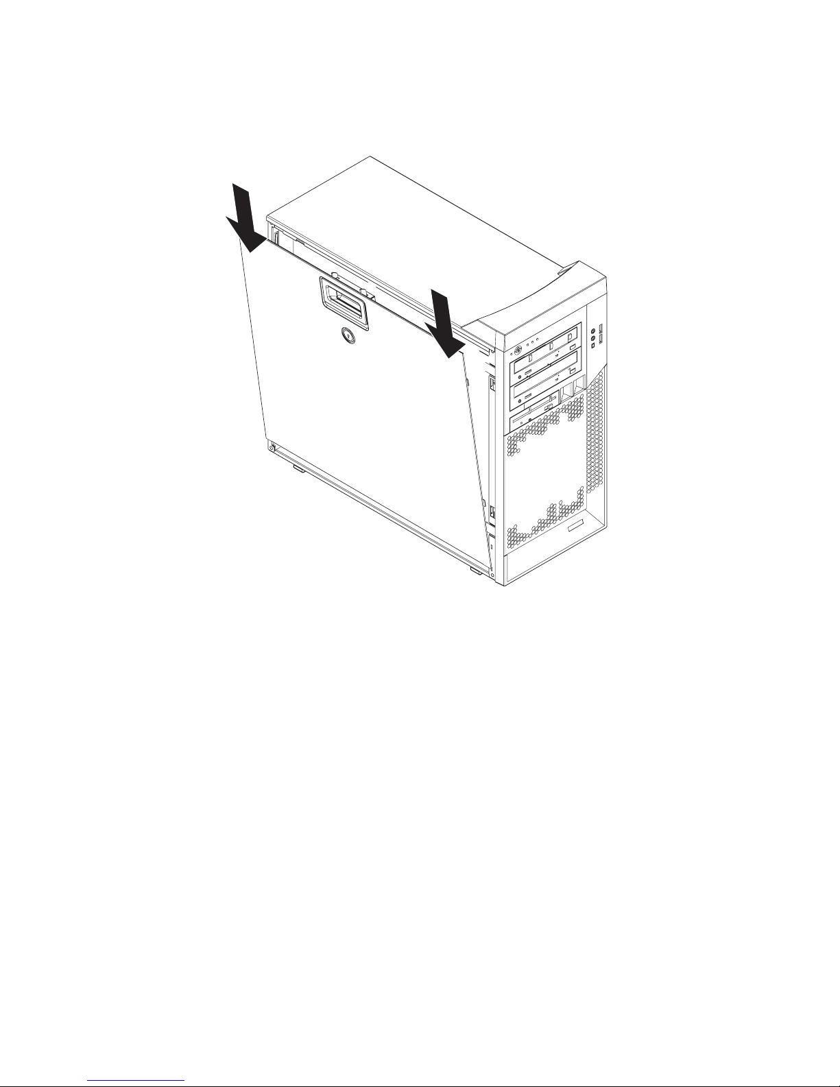
Installing the side cover
To install the side cover, complete the following steps.
Figure 9. Installing the side cover
Note: The rear adapter-retaining bracket rests against the computer side cover.
You might find it easier to lay the computer on its side to install the side cover.
1. Make sure that:
v All cables, adapters, and other components are installed and seated correctly.
v You have removed all work tools or parts from inside the computer.
v The cover-release latch is in the unlocked (opened) position before you install
the side cover.
2. If you removed the bezel, reinstall it before you install the side cover (see
“Installing the two-piece bezel” on page 35).
3. Insert the tabs inside the cover into the slots on the chassis (see Figure 9).
Note: Make sure that each tab on the side cover is in its corresponding slot
before closing the cover-release latch.
4. Close the cover-release latch to secure the side cover in place.
5. Lock the side cover, if you unlocked it during removal.
6. Reconnect the external cables and power cords to the computer; then, connect
the power cords to electrical outlets.
7. Turn on the attached devices; then, turn on the computer.
32 IBM IntelliStation Z Pro Type 9228 and 9232: Problem Determination and Service Guide
Page 51

Attention: For proper cooling and airflow, install the cover before turning on
the computer. Operating the computer with the cover removed might damage
computer components.
Removing the two-piece bezel
When working with some devices, such as additional optical drives, you must first
remove the two-piece bezel to access the device.
Notes:
1. Before you remove the upper bezel, you must first remove the lower bezel.
2. If you are only removing the lower bezel, you do not have to remove the side
cover. However, the side cover must be unlocked.
To remove the two-piece bezel, complete the following steps:
1. Read the safety information that begins on page vii and “Installation guidelines”
on page 29.
2. Turn off the computer and all attached devices; then, disconnect all external
cables and power cords.
3. Remove the side cover (see “Removing the side cover” on page 31).
4. Remove the lower bezel.
Figure 10. Removing the lower bezel
a. Press the round blue release button on the upper-right side of the lower
b. Tilt the lower bezel forward; then, lift it up to disengage the bottom tabs from
5. Remove the upper bezel.
bezel.
the chassis. Store the bezel for future use.
Chapter 4. Removing and replacing computer components 33
Page 52

Bezel clips
Figure 11. Removing the upper bezel
a. Carefully pull the two bezel clips on the left side of the upper bezel away
from the chassis.
b. Rotate the upper bezel to the right side of the computer to disengage the
two right-side tabs from the chassis. Store the bezel for future use.
34 IBM IntelliStation Z Pro Type 9228 and 9232: Problem Determination and Service Guide
Page 53

Installing the two-piece bezel
To install the two-piece bezel, complete the following steps.
Bezel clips
Figure 12. Installing the upper bezel
1. Install the upper bezel on the front of the computer chassis:
a. Insert the two right-side tabs on the upper bezel into the matching holes on
the right side of the chassis.
b. Rotate the upper bezel to the left side of the chassis and press the bezel
clips into the matching indentations on the left side of the chassis until the
bezel clips snap into place.
2. Install the lower bezel on the front of the computer.
Chapter 4. Removing and replacing computer components 35
Page 54

Figure 13. Installing the lower bezel
a. Insert the two bottom tabs on the lower bezel into the matching holes in the
front of the chassis.
b. Tilt the top of the lower bezel into position on the chassis until the lower
bezel locks securely into place.
3. Reconnect the external cables and power cords; then, turn on the attached
devices and the computer.
Removing an adapter
This section describes the removal of adapters in the PCI Express slots, PCI-X
slots 4 and 5, and PCI slot 6.
To remove an adapter, complete the following steps.
Rear adapterretention bracket
Figure 14. Removing an adapter
1. Read the safety information that begins on page vii and “Installation guidelines”
on page 29.
2. Turn off the computer and all attached devices; then, disconnect all external
cables and power cords.
3. Remove the side cover (see “Removing the side cover” on page 31).
4. Disconnect any cables to the adapter or any cables that impede access to the
adapter.
5. For full-length adapters, rotate the rear adapter-retention bracket to the fully
open (unlocked) position. Press the two blue release buttons located on the side
of the front adapter-retention bracket that faces the adapters. If you are
removing a smaller adapter, rotate only the rear adapter-retention bracket.
36 IBM IntelliStation Z Pro Type 9228 and 9232: Problem Determination and Service Guide
Expansionslot cover
Adapter
Front adapterretention bracket
Page 55

Note: Some adapters in the computer might be secured with an expansion-slot
screw. If a screw is present, remove it before proceeding to the next step.
6. Grasp the adapter and pull it out of the slot.
Attention: Expansion-slot covers must be installed in all empty slots. This
maintains the electronic emissions standards of the computer and ensures
proper ventilation of computer components.
7. If you are instructed to return the adapter, follow all packaging instructions, and
use any packaging materials for shipping that are supplied to you.
8. If you are not replacing the adapter, install an expansion-slot cover in the
expansion-slot opening.
Installing an adapter
For information about the types of adapters that the computer supports and other
information that you might consider when installing an adapter, see the User’s
Guide on the IBM IntelliStation Documentation CD.
To install an adapter, complete the following steps:
1. Check the instructions that come with the adapter for any requirements,
restrictions, or cabling instructions. It might be easier to route cables before you
install the adapter.
2. Follow the instructions that come with the adapter to set jumpers or switches, if
any.
Attention: Avoid touching the components and gold-edge connectors on the
adapter.
3. If you are installing a full-length adapter, remove the blue adapter guide (if any)
from the end of the adapter.
Figure 15. Adapter guide location
4. Carefully grasp the adapter by the top edge or upper corner and move the
adapter directly from the static-protective package to the adapter slot. Align the
adapter with the expansion-slot guides; then, press the adapter firmly into the
expansion slot.
Attention: Make sure that the adapter is correctly seated in the expansion slot
before you turn on the computer. Incomplete installation of an adapter might
damage the system board or the adapter.
Adapter guide
Chapter 4. Removing and replacing computer components 37
Page 56

Rear adapterretention bracket
Adapter
Expansionslot cover
Figure 16. Installing an adapter
Front adapterretention bracket
5. Rotate the rear adapter-retention bracket to the closed (locked) position.
6. Connect any required cables to the adapter. Make sure that they do not block
the flow of air from the fan.
7. If you have installed a full-length adapter, press the blue dot on the top retention
tab which is located on the side of the front adapter-retention bracket that faces
the fan compartment. When you press the top retention tab, the adapter locks in
place.
Note: If any adapter in the computer is large or has heavy cables attached to it,
you can secure the adapter with a screw. Insert one backup expansion-slot
screw through the top of each adapter bracket into the screw hole and secure
the adapter before proceeding to the next step.
8. Install the side cover (see “Installing the side cover” on page 32).
9. Reconnect the external cables and power cords; then, turn on the attached
devices and the computer.
38 IBM IntelliStation Z Pro Type 9228 and 9232: Problem Determination and Service Guide
Page 57
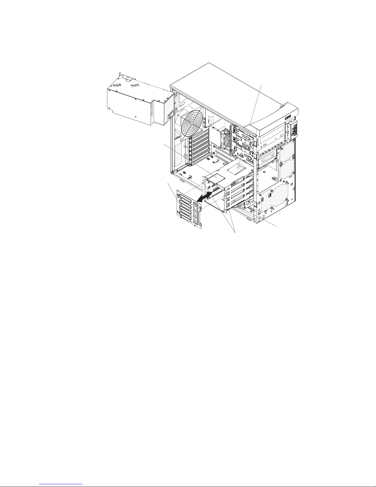
Removing the hard drive backplate
To remove the hard drive backplate, complete the following steps.
Retaining
latch
Hard drive
backplate
Retaining tab
Drive cage
Locating pins
Figure 17. Removing the hard drive backplate
release tab
1. Read the safety information that begins on page vii and “Installation guidelines”
on page 29.
2. Turn off the computer and all attached devices; then, disconnect all power
cords and external cables.
3. Remove the side cover (see “Removing the side cover” on page 31).
4. Remove the lower bezel (see “Removing the two-piece bezel” on page 33).
5. Remove the simple-swap hard disk drives that are installed in the hard disk
drive cage (see “Removing a simple-swap drive in bay 4, 5, 6, or 7” on page
51).
6. Lift the power-supply handle and rotate the power supply out of the chassis.
7. Press and hold the drive-cage release lever; then, rotate the drive cage
completely out of the chassis until the retaining tab on top of the cage locks
into place.
8. Disconnect the power cables from the system board.
9. Remove the hard drive fan assembly (see “Removing the hard disk drive fan”
on page 54) steps 6, 7, and 8.
10. Disconnect the signal cables from the hard drive backplate.
11. Press up on the retaining latch at the top of the drive cage; then, tilt the top of
the simple-swap backplate away from the drive cage until it is clear of the
locating pins.
12. Lift the backplate out of the lower lip on the drive cage.
Chapter 4. Removing and replacing computer components 39
Page 58

13. If you are instructed to return the backplate, follow all packaging instructions,
and use any packaging materials for shipping that are supplied to you.
Installing the hard drive backplate
To install the hard drive backplate, complete the following steps.
Retaining
latch
Hard drive
backplate
Retaining tab
Drive cage
Locating pins
Figure 18. Installing the hard drive backplate
release tab
1. Position the bottom edge of the backplate in the lower lip of the drive cage.
2. Tilt the top of the backplate toward the drive cage and over the locating pins
until the retaining latch is engaged.
3. Connect the signal cables to the hard drive backplate.
4. Install the hard disk drive fan assembly (see “Installing the hard disk drive fan”
on page 55) steps 2 and 3.
5. Reconnect the power cables to the system board.
6. Push the drive cage outward and press in on the drive-cage release lever;
then, rotate the drive cage completely into the chassis.
7. Press down on the power-supply release latch and rotate the power supply
into the chassis. Return the power-supply handle to the closed position.
8. Install the simple-swap hard disk drives that were removed from the hard disk
drive cage (see “Installing a simple-swap drive in bay 4, 5, 6, or 7” on page
52).
9. Install the lower bezel (see “Installing the two-piece bezel” on page 35).
10. Install the side cover (see “Installing the side cover” on page 32).
11. Lock the side cover if you unlocked it during removal.
12. Reconnect the external cables and power cords; then, turn on the attached
devices and turn on the computer.
40 IBM IntelliStation Z Pro Type 9228 and 9232: Problem Determination and Service Guide
Page 59

Removing a DIMM
To remove a DIMM, complete the following steps:
1. Read the safety information that begins on page vii and “Installation guidelines”
2. Turn off the computer and all attached devices; then, disconnect all external
3. Remove the side cover (see “Removing the side cover” on page 31).
4. Lift the power-supply handle and rotate the power supply out of the chassis.
5. Press and hold the drive-cage release lever; then, rotate the drive cage
6. Disconnect any cables that impede access to the DIMMs.
7. Carefully open the retaining clips on each end of the DIMM connector and
on page 29.
cables and power cords.
completely out of the chassis until the retaining tab on top of the cage locks into
place.
Attention: To avoid breaking the retaining clips or damaging the DIMM
connectors, open and close the clips gently.
remove the DIMM (see Figure 19).
DIMM
Retaining
clip
Figure 19. Removing a DIMM
8. If you are instructed to return the DIMM, follow all packaging instructions, and
use any packaging materials for shipping that are supplied to you.
Chapter 4. Removing and replacing computer components 41
Page 60

Installing a DIMM
The following notes describe the types of DIMMs that the computer supports and
other information that you must consider when installing DIMMs:
v When you restart the computer after adding or removing a DIMM, the computer
v The system board contains eight DIMM connectors and supports two-way
v Install only 1.8 V, 240-pin, 667 MHz, PC2-5300, DDR2 synchronous dynamic
v The amount of usable memory will be reduced depending on the system
v The DIMM options that are available for the computer are 512 MB, 1 GB, 2 GB,
v The memory controller has four fully buffered DIMM channels that are organized
displays a message that the memory configuration has changed.
memory interleaving.
random-access memory (SDRAM) with error correcting code (ECC) fully buffered
DIMMs. These DIMMs must be compatible with the latest PC2-5300 SDRAM,
fully buffered DIMM specification. For a list of supported options for the computer,
go to http://www.ibm.com/intellistation/; then, select your country and navigate to
the list of options for the computer.
configuration. A certain amount of memory must be reserved for system
resources. The basic input/output system (BIOS) displays the total amount of
installed memory and the amount of configured memory.
and 4 GB, which come in matched pairs. The computer supports a minimum of
1GB and a maximum of 32 GB of system memory.
into two branches. Each branch has two channels, and each channel controls
two DIMMs. DIMMs within the channels of a branch must be identical in size,
type, speed, and technology. The following illustration shows how the memory
controller is organized into branches and channels with two pairs of DIMMs
installed.
DIMM 2
DIMM 1
DIMM 4
DIMM 3
Channel 0 Channel 1 Channel 2 Channel 3
Branch 0
Memory Controller
DIMM 6
DIMM 5
DIMM 8
DIMM 7
Branch 1
Note: The DIMMs in the computer should be populated from the largest DIMM
to the smallest DIMM (for example 2 GB, 1 GB, 512 MB). Populating DIMMs
from the largest capacity to the smallest capacity will yield better performance,
enabling the operating system to access more of the system memory before
passing through the advanced memory buffer (AMB) to access the second DIMM
on the channel.
v The computer can operate in two major modes, mirroring and non-mirroring
(normal). The computer can also operate in a single-channel mode when one
DIMM is installed.
v The computer supports memory mirroring (mirroring mode) and online-spare
memory.
– Memory mirroring replicates data in two pairs of DIMMs simultaneously, this
allows the computer to continue working if one set of DIMMs fail.
When you use memory mirroring, consider the following information:
- The memory is reduced to half the amount of memory available. For
example, the maximum available memory is reduced from 32 GB to 16 GB
in the mirroring mode.
42 IBM IntelliStation Z Pro Type 9228 and 9232: Problem Determination and Service Guide
Page 61

- The minimum memory configuration is four identical DIMMs. You must
install identical pairs of DIMMs in all four DIMM connections (same size,
type, speed, and technology). These DIMMs must span both branches and
all four channels. For example, when you assign the first four DIMMs, you
must install two DIMMs in branch 0 (one in channel 0 and one in channel
1) and two DIMMs in branch 1 (one in channel 2 and one in channel 3).
See the following table for the installation sequence for operating in the
mirroring mode.
- When you upgrade the computer to eight DIMMs, the DIMMs in both
branches must be identical (same size, type, speed, and technology).
- Both branches operate in dual-channel mode.
The following table shows the DIMM configuration upgrade sequence
(mirroring mode).
Number of DIMMs DIMM connections
4 1,3,5,7
8 1,3,5,7,2,4,6,8
– Online-spare memory disables a failed pair of DIMMs from the system
configuration and activates an online-spare pair of DIMMs to replace the failed
pair of DIMMs. For an online-spare pair of DIMMs to be activated, you must
have installed an additional pair of DIMMs of the same speed, type, size (or
larger), and technology as the failed pair of DIMMs. When you use
online-spare memory, consider the following information:
- You cannot enable online-spare memory while the computer is operating in
mirroring mode.
- The minimum memory configuration is two double-rank DIMMs installed in
branch 0, DIMM connection 1 (in channel 0) and DIMM connection 3 (in
channel 1).
- The spare pair of DIMMs must be the same speed, type, size (or larger),
and technology as the failed pair of DIMMs.
- Branch 0 and branch 1 operate independently.
v The following notes apply when the computer operates in the non-mirroring mode
(normal mode).
– The computer comes with two 512 MB DIMMs installed in DIMM connectors 1
and 3. The second pair of DIMMs must be installed in DIMM connectors 5
and 7. The third pair of DIMMs must be installed in DIMM connectors 2 and 4.
The fourth pair of DIMMs must be installed in DIMM connectors 6 and 8.
– DIMMs must be installed in matched pairs. For example, the DIMMs in DIMM
connector 1 and 3 must be identical to each other, but do not have to be
identical to the DIMMs in DIMM connector 5 and 7. But the DIMMs in DIMM
connector 5 and 7 must be identical to each other. The DIMMs in each pair
must be the same size, speed, type, and technology as each other but do not
have to match the other pairs. You can mix compatible DIMMs from various
manufacturers. See the following table for the DIMM configuration upgrade
sequence non-mirroring mode (normal mode).
The following table shows the DIMM configuration upgrade sequence (non-mirroring
mode).
Number of DIMMs DIMM connections
First pair 1, 3
Chapter 4. Removing and replacing computer components 43
Page 62

Number of DIMMs DIMM connections
Second pair 5, 7
Third pair 2, 4
Fourth pair 6, 8
To install a DIMM, complete the following steps:
1. Make sure that the retaining clips on each end of the DIMM connector are fully
open.
2. Touch the static-protective package that contains the new DIMM to any
unpainted metal surface on the computer; then, remove the new DIMM from the
package.
3. Turn the DIMM so that the contacts align correctly with the connector.
Attention: To avoid breaking the retaining clips or damaging the DIMM
connectors, open and close the clips gently.
4. Insert the DIMM into the connector (see Figure 20). Firmly press the DIMM
straight down into the connector by applying pressure on both ends of the
DIMM simultaneously. The retaining clips snap into the locked position when the
DIMM is firmly seated in the connector. If there is a gap between the DIMM and
the retaining clips, the DIMM has not been correctly installed. Open the
retaining clips, remove the DIMM, and reinsert it.
DIMM
Retaining
clip
Figure 20. Installing a DIMM
5. Reconnect any cables that you disconnected during removal.
6. Push the drive cage outward, and press in on the drive-cage release lever;
then, rotate the drive cage into the chassis.
7. Press down on the power-supply release latch, and rotate the power supply into
the chassis. Return the power-supply handle to the closed position.
8. Install the side cover (see “Installing the side cover” on page 32).
9. Reconnect the external cables and power cords; then, turn on the attached
devices and the computer.
44 IBM IntelliStation Z Pro Type 9228 and 9232: Problem Determination and Service Guide
Page 63
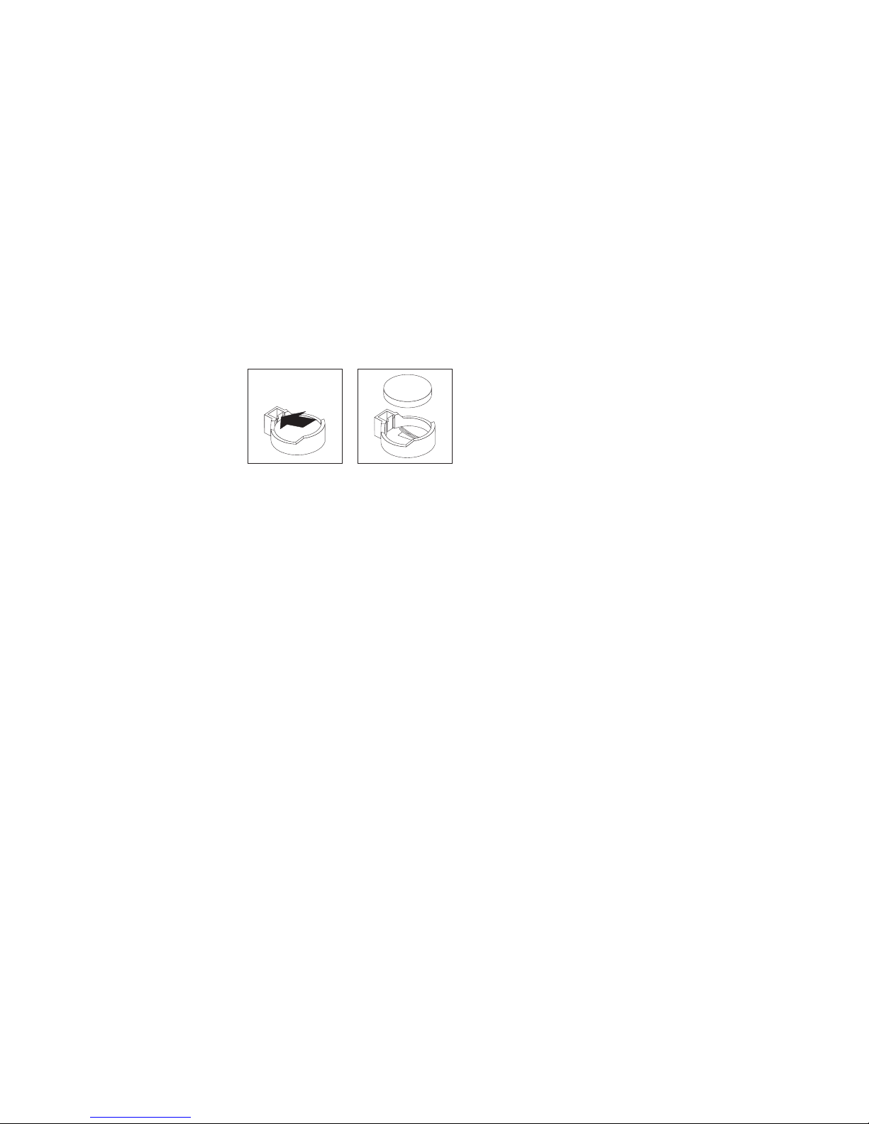
Removing the battery
To remove the battery, complete the following steps:
1. Read the safety information that begins on page vii and “Installation guidelines”
on page 29.
2. Turn off the computer and all attached devices; then, disconnect all external
cables and power cords.
3. Remove the side cover (see “Removing the side cover” on page 31).
4. Remove any adapters that impede access to the battery.
5. Remove the battery:
a. Use a fingernail to press the top of the battery clip away from the battery
(see Figure 21). The battery pops up when released.
b. Use your thumb and index finger to lift the battery from the socket.
Figure 21. Removing the battery
Installing the battery
The following notes describe information that you must consider when replacing the
battery in the computer:
v When replacing the battery, you must replace it with a lithium battery of the same
type from the same manufacturer.
v To order replacement batteries, call 1-800-426-7378 within the United States, and
1-800-465-7999 or 1-800-465-6666 within Canada. Outside the U.S. and
Canada, call your IBM marketing representative or authorized reseller.
v After you replace the battery, you must reconfigure the system and reset the
system date and time.
Chapter 4. Removing and replacing computer components 45
Page 64

v To avoid possible danger, read and follow the following safety statement.
Statement 2:
CAUTION:
When replacing the lithium battery, use only IBM Part Number 33F8354 or
an equivalent type battery recommended by the manufacturer. If your
system has a module containing a lithium battery, replace it only with the
same module type made by the same manufacturer. The battery contains
lithium and can explode if not properly used, handled, or disposed of.
Do not:
– Throw or immerse into water
– Heat to more than 100°C (212°F)
– Repair or disassemble
Dispose of the battery as required by local ordinances or regulations.
To install the battery, complete the following steps:
1. Insert the new battery:
a. Tilt the battery so that you can insert it into the socket on the side opposite
the battery clip.
b. Press the battery down into the socket (see Figure 22) until it clicks into
place. Make sure that the battery clip holds the battery securely.
Figure 22. Installing the battery
2. Reinstall any adapters that you removed.
3. Install the side cover (see “Installing the side cover” on page 32).
4. Reconnect the external cables and power cords; then, turn on the attached
devices and the computer.
5. Start the Configuration/Setup Utility program and reset the configuration:
v Set the system date and time.
v Set passwords if necessary.
v Save the configuration.
46 IBM IntelliStation Z Pro Type 9228 and 9232: Problem Determination and Service Guide
Page 65

Removing the internal speaker
The internal speaker is on the front panel of the computer.
To remove the speaker, complete the following steps.
Speaker retainer
tabs
Figure 23. Removing the speaker
1. Read the safety information that begins on page vii and “Installation guidelines”
on page 29.
2. Turn off the computer and all attached devices; then, disconnect all external
cables and power cords.
3. Remove the side cover (see “Removing the side cover” on page 31).
4. Remove the lower bezel (see “Removing the two-piece bezel” on page 33).
Note: It might be helpful to lay the computer on its left side for the remainder of
this procedure.
5. Note where the speaker wire is connected to the system board; then, carefully
disconnect the wire from the system board. See “System board internal
connectors” on page 9.
6. Press the speaker retainer tabs to detach them from the chassis.
7. Grasp the speaker and slide the speaker out of its retaining tabs toward the top
of the chassis; then, lift it out of the chassis (see Figure 23).
8. If you are instructed to return the speaker, follow all packaging instructions, and
use any packaging materials for shipping that are supplied to you.
Installing the internal speaker
To install the speaker, complete the following steps:
1. Slide the speaker into the retaining tabs in the front of the chassis.
2. Reconnect the speaker wire to the system board connector.
3. Install the lower bezel (see “Installing the two-piece bezel” on page 35).
Chapter 4. Removing and replacing computer components 47
Page 66

4. Install the side cover (see “Installing the side cover” on page 32).
5. Reconnect the external cables and power cords; then, turn on the attached
devices and the computer.
Removing and replacing Tier 2 CRUs
You can install a Tier 2 CRU yourself or request IBM to install it, at no additional
charge, under the type of warranty service that is designated for your computer.
The illustrations in this document might differ slightly from your hardware.
Removing and installing internal drives
This section describes the removal and installation of internal drives (see Figure 24
for the location of the drive bays). See the User’s Guide for more information about
the types of drives that the computer supports.
Bay 1
Bay 2
Bay 3
Bay 4
Bay 5
Bay 6
Bay 7
Figure 24. Internal drive bay locations
48 IBM IntelliStation Z Pro Type 9228 and 9232: Problem Determination and Service Guide
Page 67

Removing a drive in bay 1, 2, or 3
To remove a drive in bay 1, 2, or 3 complete the following steps.
Release
buttons
Figure 25. Removing a drive from bay 1, 2, or 3
Drive retainer
clip
1. Read the safety information that begins on page vii and “Installation guidelines”
on page 29.
2. Turn off the computer and all attached devices; then, disconnect all external
cables and power cords.
3. Remove the side cover (see “Removing the side cover” on page 31).
4. Remove the two-piece bezel (see “Removing the two-piece bezel” on page 33).
5. Disconnect the power and signal cables from the drive that you are removing.
6. To remove a drive from bay 1 or 2, release the drive from the bay by pressing
the blue release button on the side of the bay (see Figure 25). Pull the drive out
of the computer.
7. To remove a diskette drive from bay 3, press the blue release button on the side
of the bay. Pull the drive out of the front of the computer.
8. Remove the drive retainer clip from the side of the drive. Save the clip to use
when you install the replacement drive.
9. If you are instructed to return the drive, follow all packaging instructions, and
use any packaging materials for shipping that are supplied to you.
Chapter 4. Removing and replacing computer components 49
Page 68

Installing a drive in bay 1, 2, or 3
To install a drive in bay 1, 2, or 3 complete the following steps.
Release
buttons
Figure 26. Installing a drive in bay 1, 2, or 3
Drive retainer
clip
1. If you are replacing a removed drive with a new drive, make sure that:
v You have all the cables and other equipment that is specified in the
documentation that comes with the new drive.
v You check the instructions that come with the new drive to determine whether
you must set any switches or jumpers on the drive.
v You have removed the drive clip on the side of the original drive and have it
available for installation on the new drive.
Note: If you are installing a drive that contains a laser, review the following
safety precaution.
50 IBM IntelliStation Z Pro Type 9228 and 9232: Problem Determination and Service Guide
Page 69

Statement 3
CAUTION:
When laser products (such as CD-ROMs, DVD-ROM drives, fiber optic devices, or
transmitters) are installed, note the following:
v Do not remove the covers. Removing the covers of the laser product could result in
exposure to hazardous laser radiation. There are no serviceable parts inside the
device.
v Use of controls or adjustments or performance of procedures other than those
specified herein might result in hazardous radiation exposure.
DANGER
Some laser products contain an embedded Class 3A or Class 3B laser diode. Note
the following:
Laser radiation when open. Do not stare into the beam, do not view directly with
optical instruments, and avoid direct exposure to the beam.
Class 1 Laser Product
Laser Klasse 1
Laser Klass 1
Luokan 1 Laserlaite
Appareil A Laser de Classe 1
`
2. Touch the static-protective package that contains the new drive to any unpainted
metal surface on the computer; then, remove the drive from the package and
place it on a static-protective surface.
3. Follow the instructions that come with the drive to set the jumpers or switches.
Notes:
a. You might find it easier to install the new drive into the opening on the front
and then attach the cables.
b. If you are installing a 3.5-in. drive in bay 2, attach a 5.25-in. conversion kit
to the 3.5-in. drive.
4. Install the blue drive-retainer clip into the screw holes on the side of the drive.
5. Push the drive into the front of the bay until it clicks into place (see Figure 26).
6. Reconnect the power and signal cables to the drive.
Note: Route the signal cable so that it does not block the airflow to the rear of
the drives or over the microprocessor.
7. Install the bezel (see “Installing the two-piece bezel” on page 35).
8. Install the side cover (see “Installing the side cover” on page 32).
9. Reconnect the external cables and power cords; then, turn on the attached
devices and the computer.
Removing a simple-swap drive in bay 4, 5, 6, or 7
This procedure applies to a computer that has simple-swap hard disk drives.
Chapter 4. Removing and replacing computer components 51
Page 70

To remove a simple-swap drive in bay 4, 5, 6, or 7 complete the following steps.
Figure 27. Removing a simple-swap hard disk drive
1. Read the safety information that begins on page vii and “Installation guidelines”
on page 29.
2. Turn off the computer and all attached devices; then, disconnect all external
cables and power cords.
3. Unlock the side cover. The bezel will not disengage from the computer if the
cover is locked. You do not have to remove the side cover.
4. Remove the lower bezel (see “Removing the two-piece bezel” on page 33).
5. Pull the loops of the drive assembly that is to be removed toward each other;
then, pull the assembly out of the bay.
6. If you are instructed to return the drive, follow all packaging instructions, and
use any packaging materials for shipping that are supplied to you.
Installing a simple-swap drive in bay 4, 5, 6, or 7
This procedure applies to a computer that has simple-swap hard disk drives.
Some models come with simple-swap SATA or SAS hard disk drives, which are
accessible from the front of the computer. Before you install a simple-swap SATA or
SAS hard disk drive, read the following information:
v Read the documentation that comes with the hard disk drive for cabling
instructions.
v You can install four simple-swap SATA or SAS hard disk drives in the computer.
Drives are installed starting in bay 4. Additional drives are then installed in bays
5, 6, and 7.
To install a simple-swap hard disk drive, complete the following steps.
52 IBM IntelliStation Z Pro Type 9228 and 9232: Problem Determination and Service Guide
Page 71

Figure 28. Installing a simple-swap hard disk drive
1. Touch the static-protective package that contains the hard disk drive to any
unpainted metal surface on the computer; then, remove the drive from the
package and place it on a static-protective surface.
2. Align the drive assembly with the guide rails in the bay (the connector end of
the drive goes in first). See Figure 28.
3. Pull the loops of the drive assembly toward each other; then, carefully slide
the drive assembly into the drive bay until the drive assembly connects to the
back panel connector at the rear of the drive bay (you should hear a click).
Note: Do not release the loops on the drive assembly until the drive
assembly is completely seated.
4. Replace the lower bezel (see “Installing the two-piece bezel” on page 35).
5. Install the side cover, if you removed it (see “Installing the side cover” on
page 32).
6. Lock the side cover.
7. Reconnect the external cables and power cords.
8. Turn on the attached devices and the computer.
Chapter 4. Removing and replacing computer components 53
Page 72

Removing the hard disk drive fan
Attention:
v Replace a failed fan within 48 hours.
v To ensure proper cooling and airflow, do not operate the computer for more than
30 minutes with the side cover removed.
To remove the hard disk drive fan assembly, complete the following steps.
Retaining
latch
Retaining tab
Drive-cage
Hard disk drive
fan assembly
Figure 29. Removing the hard disk drive fan assembly
release lever
1. Read the safety information that begins on page vii and “Installation guidelines”
on page 29.
2. Turn off the computer and all attached devices; then, disconnect all external
cables and power cords.
3. Remove the side cover (see “Removing the side cover” on page 31).
4. Lift the power-supply handle and rotate the power supply out of the chassis.
5. Press and hold the drive-cage release lever; then, rotate the drive cage
completely out of the chassis until the retaining tab on top of the cage locks
into place.
6. Disconnect the hard disk drive fan cable from the system board, and note the
location of the connector (see “System board internal connectors” on page 9).
7. Pull up on the fan-assembly retainer tabs at the blue press points; then, lift the
assembly away from the drive cage.
8. Set the fan assembly on a level work surface with the fan facing up (see
Figure 30 on page 55).
54 IBM IntelliStation Z Pro Type 9228 and 9232: Problem Determination and Service Guide
Page 73

Hard drive
fan
Hard drive
baffle
Figure 30. Removing the hard disk drive fan
9. Use side cutters to sever the four grommets that secure the fan to the duct,
and remove the fan.
Note: Grommets are provided with the replacement fan.
10. If you are instructed to return the hard disk drive fan assembly, follow all
packaging instructions, and use any packaging materials for shipping that are
supplied to you.
Installing the hard disk drive fan
Attention:
v Replace a failed fan within 48 hours.
v To ensure proper cooling and airflow, do not operate the computer for more than
30 minutes with the side cover removed.
To install the hard disk drive fan assembly, complete the following steps:
1. Position the fan so that the grommets protrude through the holes in the fan
assembly; then, use needle-nose pliers to pull the grommets through the holes
(see Figure 31).
Chapter 4. Removing and replacing computer components 55
Page 74

Hard drive
fan
Hard drive
baffle
Figure 31. Installing the hard disk drive fan
2. Insert the fan-assembly retainer tabs into the corresponding slots in the drive
cage; then, press the fan assembly onto the drive cage (see Figure 32).
Retaining tab
Retaining
latch
Hard disk drive
fan assembly
Figure 32. Installing the hard disk drive fan assembly
3. Connect the hard disk drive fan cable to the system board (see “System board
internal connectors” on page 9).
56 IBM IntelliStation Z Pro Type 9228 and 9232: Problem Determination and Service Guide
Drive-cage
release lever
Page 75

4. Push the drive cage outward, and press in on the drive-cage release lever;
then, rotate the drive cage completely into the chassis.
5. Press down on the power-supply release latch and rotate the power supply into
the chassis. Return the power supply handle to the closed position.
6. Replace the side cover (see “Installing the side cover” on page 32).
7. Reconnect the external cables and power cords; then, turn on the attached
devices and the computer.
Removing the rear fan
Attention:
v Replace a failed fan within 48 hours.
v To ensure proper cooling and airflow, do not operate the computer for more than
30 minutes with the side cover removed.
To remove the rear fan, complete the following steps.
Grommets
Rear fan
Figure 33. Removing the rear system fan
1. Read the safety information that begins on page vii and “Installation guidelines”
on page 29.
2. Turn off the computer and all attached devices; then, disconnect all external
cables and power cords.
3. Remove the side cover (see “Removing the side cover” on page 31).
4. Remove any adapters that impede access to the fan and the fan connector on
the system board (see “Removing an adapter” on page 36).
5. Disconnect the rear fan cable from the system board, and note the location of
the connector (see “System board internal connectors” on page 9).
6. Grasp the rear fan and pull firmly, extending the rubber extensions (grommets)
that secure the fan to the chassis. Pull the grommets through the holes in the
fan or chassis and remove them or use side cutters to cut the grommets.
Chapter 4. Removing and replacing computer components 57
Page 76

Note: Grommets are provided with the replacement fan.
7. Pull the rear system fan up and out of the chassis, making sure that no
grommets are left loose in the computer.
8. If you are instructed to return the rear fan assembly, follow all packaging
instructions, and use any packaging materials for shipping that are supplied to
you.
Installing the rear fan
Attention:
v Replace a failed fan within 48 hours.
v To ensure proper cooling and airflow, do not operate the computer for more than
30 minutes with the side cover removed.
To install the rear fan, complete the following steps.
Grommets
Rear fan
Figure 34. Installing the rear system fan
1. Position the fan so that the grommets protrude through the holes in the chassis;
then, use needle-nose pliers to pull the grommets through the holes from
outside the chassis.
2. Connect the rear fan cable to the system board (see “System board internal
connectors” on page 9).
3. Install any adapters that you removed (see “Installing an adapter” on page 37).
4. Replace the side cover (see “Installing the side cover” on page 32).
5. Reconnect the external cables and power cords; then, turn on the attached
devices and the computer.
58 IBM IntelliStation Z Pro Type 9228 and 9232: Problem Determination and Service Guide
Page 77
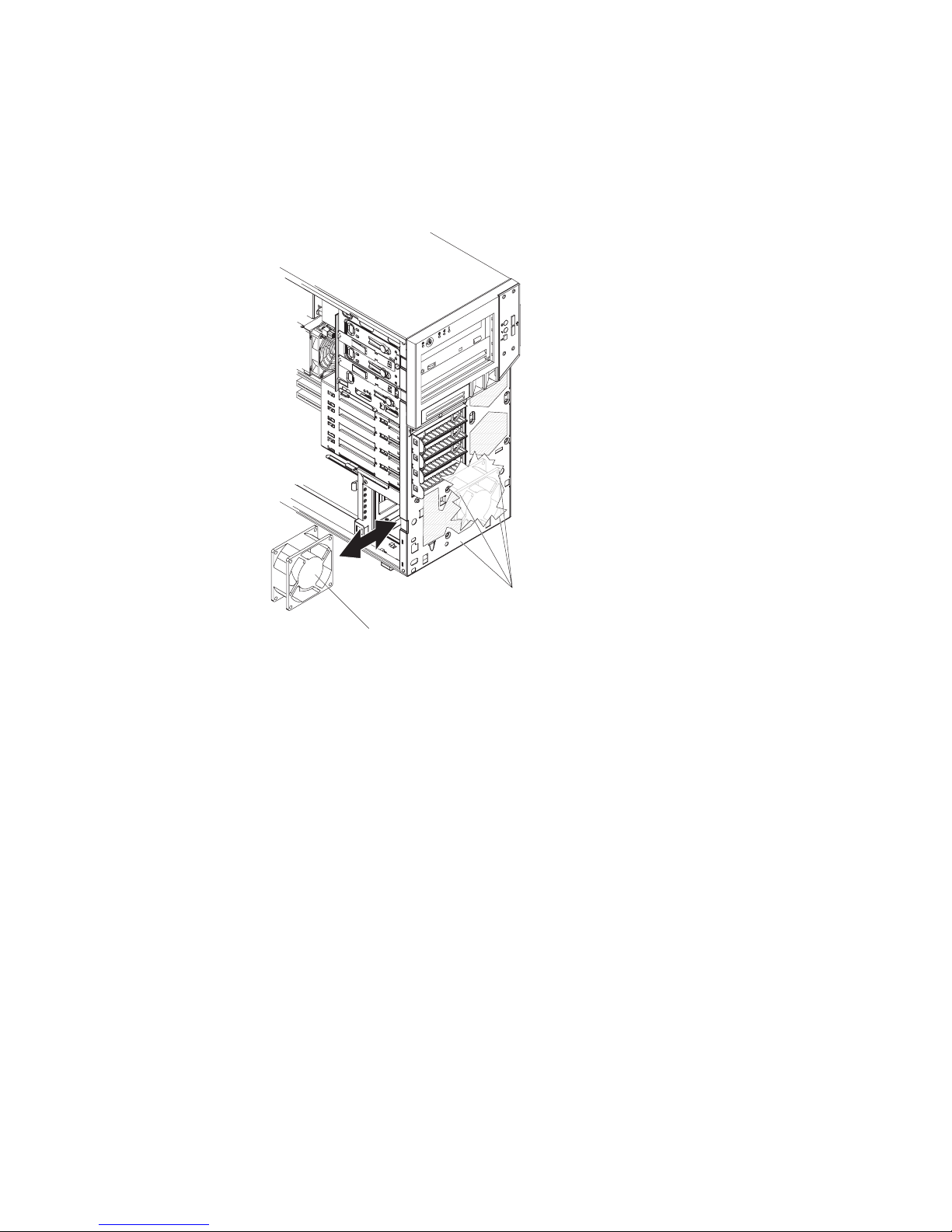
Removing the expansion slot fan
Attention:
v Replace a failed fan within 48 hours.
v To ensure proper cooling and airflow, do not operate the computer for more than
30 minutes with the side cover off.
Fan grommets
Expansion slot fan
Figure 35. Removing the expansion slot fan
To remove the expansion slot fan, complete the following steps.
1. Read the safety information that begins on page vii and “Installation guidelines”
on page 29.
2. Turn off the computer and all attached devices; then, disconnect all external
cables and power cords.
3. Remove the side cover (see “Removing the side cover” on page 31).
4. Remove the lower bezel (see “Removing the two-piece bezel” on page 33).
5. Remove any adapters that impede access to the fan and the fan connector on
the system board (see “Removing an adapter” on page 36).
6. Note where the expansion slot fan cable is connected to the system board, and
disconnect the cable from the system board (see “System board internal
connectors” on page 9).
7. Grasp the expansion slot fan and pull firmly, extending the rubber extensions
(grommets). Pull the grommets through the holes in the fan or chassis and
remove them, or use side cutters to cut the grommets.
Note: Grommets are provided with the replacement fan.
8. Pull the expansion slot fan out of the chassis.
9. If you are instructed to return the expansion slot fan, follow all packaging
instructions, and use any packaging materials for shipping that are supplied to
you.
Chapter 4. Removing and replacing computer components 59
Page 78

Installing the expansion slot fan
Attention:
v Replace a failed fan within 48 hours.
v To ensure proper cooling and airflow, do not operate the computer for more than
30 minutes with the side cover off.
Fan grommets
Expansion slot fan
Figure 36. Installing the expansion slot fan
To install the expansion slot fan, complete the following steps.
1. Position the replacement fan so that the grommets protrude through the holes in
the chassis; then, use needle-nose pliers to pull the grommets through the holes
from outside the chassis.
2. Connect the fan cable to the system board (see “System board internal
connectors” on page 9).
3. Install any adapters that you removed (see “Installing an adapter” on page 37).
4. Replace the side cover (see “Removing the side cover” on page 31).
5. Reconnect the external cables and power cords; then, turn on the attached
devices and the computer.
Removing the mini-PCI Express adapter
To remove the mini-PCI Express adapter, complete the following steps.
60 IBM IntelliStation Z Pro Type 9228 and 9232: Problem Determination and Service Guide
Page 79

Mini-PCI Express
adapter
Mini-PCI Express
connector
Figure 37. Removing the mini-PCI Express adapter
1. Read the safety information that begins on page vii and “Installation guidelines”
on page 29.
2. Turn off the computer and all attached devices; then, disconnect all power cords
and external cables.
3. Remove the side cover (see “Removing the side cover” on page 31).
4. Lift the power-supply handle and rotate the power supply out of the chassis.
5. Press and hold the drive-cage release lever; then, rotate the drive cage
completely out of the chassis until the retaining tab on top of the cage locks into
place.
6. Disconnect the signal cables from the mini-PCI Express adapter.
7. Depress the white retaining clip for the mini-PCI Express adapter; then, pull it
away from the system board until it disengages from the mini-PCI Express
connector.
8. If you are instructed to return the mini-PCI Express adapter, follow all packaging
instructions, and use any packaging materials for shipping that are supplied to
you.
Chapter 4. Removing and replacing computer components 61
Page 80

Installing the mini-PCI Express adapter
To install the mini-PCI Express adapter, complete the following steps.
Mini-PCI Express
connector
Figure 38. Installing the mini-PCI Express adapter
1. Touch the static-protective package that contains the mini-PCI Express adapter
to any unpainted surface on the outside of the computer; then, remove the
mini-PCI Express adapter from the package.
2. Position the mini-PCI Express adapter over the mini-PCI Express connector;
then, press the mini-PCI Express adapter firmly into the mini-PCI Express
connector.
3. Connect the signal cables to the mini-PCI Express adapter.
4. Push the drive cage outward, and press in on the drive-cage release lever;
then, rotate the drive cage completely into the chassis.
5. Press down on the power-supply release latch and rotate the power supply into
the chassis. Return the power supply handle to the closed position.
6. Install the side cover (see “Installing the side cover” on page 32).
7. Reconnect the external cables and power cords; then, turn on the attached
devices and turn on the computer.
Mini-PCI Express
adapter
62 IBM IntelliStation Z Pro Type 9228 and 9232: Problem Determination and Service Guide
Page 81

Removing the power switch/LED assembly
To remove the power switch/LED assembly, complete the following steps.
Release tab
Figure 39. Removing the power switch/LED assembly
1. Read the safety information that begins on page vii and “Installation guidelines”
on page 29.
2. Turn off the computer and all attached devices; then, disconnect all external
cables and power cords.
3. Remove the side cover (see “Removing the side cover” on page 31).
4. If an optical drive is installed in bay 1 (see “Removing the two-piece bezel” on
page 33).
Note: It might be helpful to lay the computer on its left side for the remainder of
this procedure.
5. Release the drive from bay one by pressing the blue release button on the side
of the bay; then, pull the drive out slightly.
6. Note where the power-switch/LED assembly cable connects to the system
board; then, carefully disconnect the cable from the system board.
7. From inside the chassis, press inward on the power-switch release tab (see
Figure 39).
8. Pull the assembly toward the rear of the chassis and remove it.
9. If you are instructed to return the power switch/LED assembly, follow all
packaging instructions, and use any packaging materials for shipping that are
supplied to you.
Chapter 4. Removing and replacing computer components 63
Page 82

Installing the power switch/LED assembly
To install the power switch/LED assembly, complete the following steps.
Release tab
Figure 40. Installing the power switch/LED assembly
1. From inside the chassis, push the power switch/LED assembly toward the front
of the chassis until the assembly engages the power switch release tab and
clicks into place (see Figure 39).
2. Reconnect the power switch/LED assembly cable to the system board.
3. If an optical drive is in bay 1, push the drive into the drive bay, until it snaps in
place.
4. Install the front bezel (see “Installing the two-piece bezel” on page 35).
5. Install the side cover (see “Installing the side cover” on page 32).
6. Reconnect the external cables and power cords; then, turn on the attached
devices and the computer.
64 IBM IntelliStation Z Pro Type 9228 and 9232: Problem Determination and Service Guide
Page 83

Removing the front card/bracket assembly
To remove the front card/bracket assembly, complete the following steps.
Figure 41. Removing the card/bracket assembly
1. Read the safety information that begins on page vii and “Installation guidelines”
on page 29.
2. Turn off the computer and all attached devices; then, disconnect all external
cables and power cords.
3. Remove the side cover (see “Removing the side cover” on page 31).
4. Remove the bezel (see “Removing the two-piece bezel” on page 33).
5. Press the latch on the top of the assembly; the top of the assembly detaches
from the chassis (see Figure 41).
6. Remove the tab on the bottom part of the assembly from the slot in the chassis.
7. Pull the assembly out slightly, and detach the two cables from the back of the
assembly.
8. If you are instructed to return the card/bracket assembly, follow all packaging
instructions, and use any packaging materials for shipping that are supplied to
you.
Chapter 4. Removing and replacing computer components 65
Page 84

Installing the front card/bracket assembly
To install the front card/bracket assembly, complete the following steps.
Figure 42. Installing the card/bracket assembly
1. Attach the two cables to the back of the card/bracket assembly.
2. Install the bottom tab of the card/bracket assembly into the slot in the chassis;
then, press the top of the assembly into the chassis.
3. Install the bezel (see “Installing the two-piece bezel” on page 35).
4. Install the side cover (see “Installing the side cover” on page 32).
5. Reconnect the external cables and power cords; then, turn on the attached
devices and the computer.
66 IBM IntelliStation Z Pro Type 9228 and 9232: Problem Determination and Service Guide
Page 85

Removing and replacing FRUs
FRUs must be installed only by trained service technicians.
The illustrations in this document might differ slightly from the hardware.
Removing the front adapter-retention bracket
To remove the front adapter-retention bracket, complete the following steps.
Release tab
Front view
Pivot
points
Rear view
Figure 43. Removing front adapter-retention bracket
1. Read the safety information that begins on page vii and “Installation guidelines”
on page 29.
2. Turn off the computer and all attached devices; then, disconnect all external
cables and power cords.
3. Remove the side cover (see “Removing the side cover” on page 31).
Note: It might be helpful to lay the computer on its left side for the remainder of
this procedure.
Chapter 4. Removing and replacing computer components 67
Page 86

4. Remove any full-length adapters that are installed (see “Removing an adapter”
on page 36).
5. Press the blue dot on the bottom retention tab of the front adapter-retention
bracket; then, rotate the retention bracket to a 45 degree angle. This tab is
located inside the fan compartment that is next to the front adapter-retention
bracket.
6. Push the top and bottom sides of the adapter-retention bracket out of the
notches that secure the retention bracket to the chassis, (see Figure 43).
Remove the retention bracket from the chassis.
7. If you are instructed to return the adapter-retention bracket, follow all packaging
instructions, and use any packaging materials for shipping that are supplied to
you.
Installing the front adapter-retention bracket
To install the front adapter-retention bracket, complete the following steps.
Release tab
Front view
Pivot
points
Rear view
Figure 44. Installing the front adapter-retention bracket
1. Engage the top and bottom sides of the front adapter-retention bracket with the
front adapter-retention bracket openings in the chassis (see Figure 44).
68 IBM IntelliStation Z Pro Type 9228 and 9232: Problem Determination and Service Guide
Page 87

2. Rotate the front adapter-retention bracket back into the chassis.
3. Install any full-length adapters that you removed (see “Installing an adapter” on
page 37).
4. Install the side cover (see “Installing the side cover” on page 32).
5. Reconnect the external cables and power cords; then, turn on the attached
devices and the computer.
Removing the rear adapter-retention bracket
To remove the rear adapter-retention bracket, complete the following steps.
Rear adapter
retention bracket
Figure 45. Removing the rear adapter-retention bracket
1. Read the safety information that begins on page vii and “Installation guidelines”
on page 29.
2. Turn off the computer and all attached devices; then, disconnect all external
cables and power cords.
3. Remove the side cover (see “Removing the side cover” on page 31).
4. Remove all adapters that are installed (see “Removing an adapter” on page 36).
5. Rotate the rear adapter-retention bracket to a 45-degree angle.
6. Press the top and bottom retention tabs of the adapter-retention bracket toward
each other; then, remove the adapter-retention bracket from the chassis.
7. If you are instructed to return the adapter-retention bracket, follow all packaging
instructions, and use any packaging materials for shipping that are supplied to
you.
Chapter 4. Removing and replacing computer components 69
Page 88

Installing the rear adapter-retention bracket
To install the rear adapter-retention bracket, complete the following steps.
Rear adapter
retention bracket
Figure 46. Installing the rear adapter-retention bracket
1. Engage the top and bottom release tabs of the rear adapter-retention bracket
with the openings in the chassis, until the release tabs lock securely in place
(see Figure 46).
2. Rotate the rear adapter-retention bracket to the locked (closed) position.
3. Replace all adapters that you removed (see “Installing an adapter” on page 37).
4. Replace the side cover (see “Installing the side cover” on page 32).
5. Reconnect the external cables and power cords to the computer; then, connect
the power cords to electrical outlets. Turn on the attached devices and turn on
the computer.
Removing the DIMM fan assembly
Attention:
v Replace a failed fan within 48 hours.
v To ensure proper cooling and airflow, do not operate the computer for more than
30 minutes with the side cover off.
To remove the DIMM fan assembly, complete the following steps:
1. Read the safety information that begins on page vii and “Installation guidelines”
on page 29.
2. Turn off the computer and all attached devices; then, disconnect all external
cables and power cords.
3. Remove the side cover (see “Removing the side cover” on page 31).
4. Remove the bezel (see “Removing the two-piece bezel” on page 33).
5. Lift the power-supply handle and rotate the power supply out of the chassis.
70 IBM IntelliStation Z Pro Type 9228 and 9232: Problem Determination and Service Guide
Page 89

6. Press and hold the drive-cage release lever; then, rotate the drive cage
completely out of the chassis until the retaining tab on top of the cage locks
into place (see Figure 47).
DIMM airflow
guide
Figure 47. DIMM airflow guide
7. If any cables are routed through the DIMM fan baffle, remove them before
removing the DIMM fan baffle.
8. From inside the chassis, grasp the DIMM fan baffle and pull it out of the
chassis (see Figure 48).
Chapter 4. Removing and replacing computer components 71
Page 90

DIMM fan baffle
Figure 48. Removing the DIMM fan baffle
9. Disconnect the DIMM fan cable from the system board, and note the location
of the connector (see “System board internal connectors” on page 9).
10. Grasp the DIMM fan and pull firmly, extending the rubber extensions
(grommets) that secure the fan to the chassis. Pull the grommets through the
holes in the fan or chassis and remove them, or use side cutters to cut the
grommets (see Figure 49).
Note: Grommets are provided with the replacement fan.
72 IBM IntelliStation Z Pro Type 9228 and 9232: Problem Determination and Service Guide
Page 91

DIMM fan
Figure 49. Removing the DIMM fan
11. Remove the fan from the chassis, making sure that no grommets are left loose
in the chassis.
12. If you are instructed to return the DIMM fan assembly, follow all packaging
instructions, and use any packaging materials for shipping that are supplied to
you.
Installing the DIMM fan assembly
Attention:
v Replace a failed fan within 48 hours.
v To ensure proper cooling and airflow, do not operate the computer for more than
30 minutes with the side cover off.
To install the DIMM fan assembly, complete the following steps:
1. Position the fan so that the grommets protrude through the holes in the chassis;
then, use needle-nose pliers to pull the grommets through the holes from
outside the chassis (see Figure 50).
Fan grommets
Chapter 4. Removing and replacing computer components 73
Page 92

Fan grommets
DIMM fan
Figure 50. Installing the DIMM fan
2. Connect the DIMM fan cable to the system board (see “System board internal
connectors” on page 9).
3. Slide the fan baffle into the fan baffle tab in the front of the chassis until it locks
in place (see Figure 51).
DIMM fan baffle
Figure 51. Installing the DIMM fan baffle
74 IBM IntelliStation Z Pro Type 9228 and 9232: Problem Determination and Service Guide
Page 93

4. Secure any cables that you removed from the fan baffle.
5. Push the drive cage outward, and press in on the drive-cage release lever;
then, rotate the drive cage completely into the chassis.
6. Press down on the power-supply release latch and rotate the power supply into
the chassis. Return the power-supply handle into position.
7. Replace the bezel (see “Installing the two-piece bezel” on page 35).
8. Replace the side cover (see “Installing the side cover” on page 32).
9. Reconnect all external cables and power cords; then, turn on all attached
devices and the computer.
Removing the microprocessor and fan sink
To remove the microprocessor and fan sink, complete the following steps:
1. Read the safety information that begins on page vii and “Installation guidelines”
on page 29.
2. Turn off the computer and all attached devices; then, disconnect all external
cables and power cords.
3. Turn the computer on its side so that it is lying flat, with the cover facing up.
4. Remove the side cover (see “Removing the side cover” on page 31).
5. Lift the power-supply handle and rotate the power supply out of the chassis.
6. Press and hold the drive-cage release lever; then, rotate the drive cage
completely out of the chassis until the retaining tab on top of the cage locks
into place.
7. Disconnect any cables that impede access to the fan sink and microprocessor.
Attention: The fan-sink retention lever is spring-loaded when the fan sink is
in place. Releasing the lever too quickly or allowing it to spring upward can
damage the fan sink and surrounding components.
8. To remove the fan sink from the microprocessor complete the following steps.
Chapter 4. Removing and replacing computer components 75
Page 94
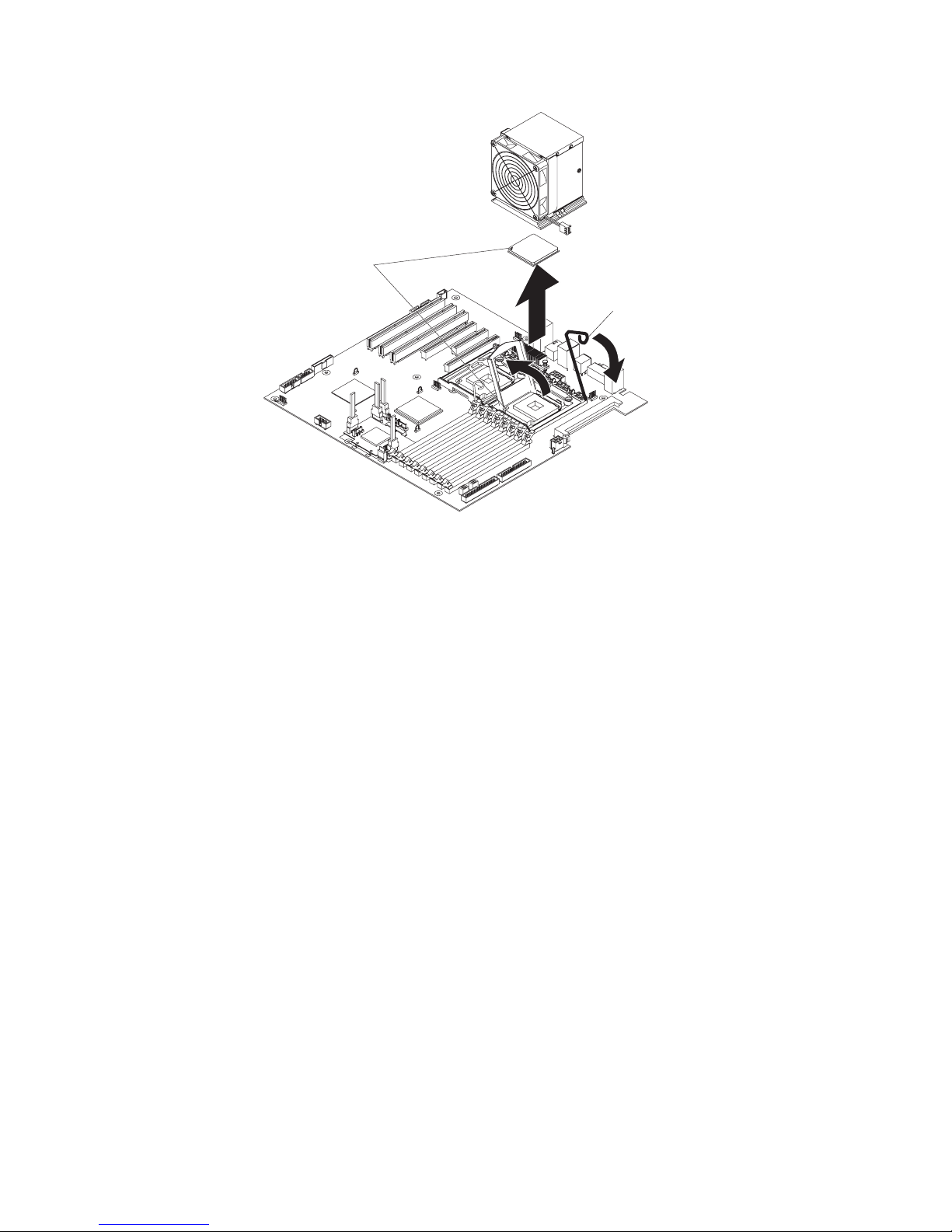
Orientation indicators
Fan-sink retention
lever
Figure 52. Removing the fan sink and microprocessor
a. Disconnect the fan-sink cable from the system board (see “System board
internal connectors” on page 9).
b. Release the fan-sink retention lever by pressing down on the end, moving
it to the side and slowly releasing it to the open (up) position.
Important: Be careful when handling the microprocessor and fan sink. If
the microprocessor and fan sink will be reused, do not contaminate the
thermal material between them.
c. Tip the top of the fan sink toward the front of the chassis while sliding it
away from the lower flange of the retention module; then, remove it from
the chassis. After removal, place the fan sink on its side on a clean, flat
surface.
Attention: The microprocessor retention latch is spring-loaded when the
microprocessor is in place. Releasing the latch too quickly or allowing it to
spring upward can damage the microprocessor and surrounding
components.
9. Release the microprocessor retention latch by pressing down on the end,
moving it to the side, and slowly releasing it to the open (up) position (see
Figure 53).
10. Open the microprocessor bracket frame by lifting up the tab on the top edge
(see Figure 53).
Attention: Use the vacuum tool that comes with the replacement part to
remove the microprocessor. Dropping the microprocessor during removal can
damage the contacts. Also, contaminants on the microprocessor contacts, such
as oil from your skin, can cause connection failures between the contacts and
the socket.
76 IBM IntelliStation Z Pro Type 9228 and 9232: Problem Determination and Service Guide
Page 95

Microprocessor
retention latch
Microprocessor
bracket frame
Figure 53. Microprocessor bracket frame
11. Remove the microprocessor by using the vacuum tool and completing the
following steps (see Figure 54).
Vacuum tool
Microprocessor
Socket
Figure 54. Removing the microprocessor
a. Squeeze and hold the bladder of the vacuum tool; then, place the suction
cup on the microprocessor and release the bladder.
b. Using the tool, carefully lift the microprocessor straight up and out of the
socket, and place it on a static-protective surface.
c. Squeeze the bladder of the vacuum tool to release the microprocessor from
the suction cup.
12. If you are instructed to return the microprocessor and fan sink, follow all
packaging instructions, and use any packaging materials for shipping that are
supplied to you.
Installing the microprocessor and fan sink
The following notes describe information that you must consider when installing an
additional microprocessor in the computer:
v Read the documentation that comes with the microprocessor to determine
whether you must update the computer BIOS code. The most current level of
BIOS code for the computer is available from http://www.ibm.com/support/.
Chapter 4. Removing and replacing computer components 77
Page 96

v To ensure proper computer operation, use microprocessors that have the same
cache size and type, and the same clock speed. Microprocessor internal and
external clock frequencies must be identical. You can use the
Configuration/Setup Utility program to determine the specific type of
microprocessor on the system board.
Important: The first microprocessor must always be installed in the
microprocessor 1 socket.
v The microprocessor speeds are automatically set for this computer; therefore,
you do not have to set any microprocessor frequency-selection jumpers or
switches.
v Terminator cards are not required for empty microprocessor sockets.
v For additional illustrations of the system-board components, see “System board
option connectors” on page 8.
v To order additional microprocessor options, contact your IBM marketing
representative or authorized reseller.
v For a list of supported microprocessor options for your computer, see
http://www.ibm.com/servers/eserver/serverproven/compat/us/iserver.html/.
The Microsoft Windows XP operating system that comes preinstalled on the
computer automatically configures itself when an additional microprocessor is
installed. Other operating systems might have to be manually configured to support
an additional microprocessor.
To install the microprocessor and the fan sink, complete the following steps.
1. Make sure that the microprocessor socket lever and cover are in the fully open
position.
Attention: Use the vacuum tool that comes with the replacement part to
install the microprocessor. Dropping the microprocessor during installation can
damage the contacts. Also, contaminants on the microprocessor contacts, such
as oil from your skin, can cause connection failures between the contacts and
the socket.
2. Install the microprocessor.
78 IBM IntelliStation Z Pro Type 9228 and 9232: Problem Determination and Service Guide
Page 97

Vacuum tool
Microprocessor
Socket
Figure 55. Installing the microprocessor
a. Squeeze and hold the bladder of the vacuum tool; then, place the suction
cup on the microprocessor and release the bladder (see Figure 55).
Note: To maintain the correct orientation between the microprocessor and
the microprocessor socket during installation, observe the following
information:
v The microprocessor has two notches that are keyed to two tabs on the
sides of the socket.
v A triangle-shaped indicator on one corner of the microprocessor points
to a 45-degree angle on one corner of the socket.
b. Using the vacuum tool, carefully place the microprocessor into the socket.
c. Squeeze the bladder of the vacuum tool to release the microprocessor
from the suction cup.
3. Close the microprocessor bracket frame; then, close the microprocessor
retention latch and lock it securely in place (see Figure 56).
Figure 56. Microprocessor bracket frame
4. Install the fan sink.
a. Make sure that the fan-sink retention lever is in the fully open position.
Chapter 4. Removing and replacing computer components 79
Page 98

Important: Be careful when handling the microprocessor and fan sink. Do
not contaminate the thermal material between them.
b. Slide the bottom edge of the fan sink under the lower flange of the
retention module; then, place the top of the fan sink onto the top of the
retention module.
c. Close the fan-sink retention lever and lock it securely in place.
Orientation indicators
Fan-sink retention
lever
Figure 57. Installing the fan sink and microprocessor
5. Reconnect the fan-sink cable to the system board (see “System board internal
connectors” on page 9).
6. Reconnect any cables that you disconnected during the removal of the original
microprocessor.
7. Push the drive cage outward, and press in on the drive-cage release lever;
then, rotate the drive cage completely into the chassis.
8. Press down on the power-supply release latch and rotate the power supply
into the chassis. Return the power supply handle to the closed position.
9. Install the side cover (see “Installing the side cover” on page 32).
10. Reconnect the external cables and power cords; then, turn on the attached
devices and the computer.
Removing the power supply
When you remove or install a power supply, observe the following precautions.
Statement 8:
80 IBM IntelliStation Z Pro Type 9228 and 9232: Problem Determination and Service Guide
Page 99

CAUTION:
Never remove the cover on a power supply or any part that has the following
label attached.
Hazardous voltage, current, and energy levels are present inside any
component that has this label attached. There are no serviceable parts inside
these components. If you suspect a problem with one of these parts, contact
a service technician.
To remove the power supply, complete the following steps.
Retaining screws
Figure 58. Removing the power supply
1. Read the safety information that begins on page vii and “Installation guidelines”
on page 29.
2. Turn off the computer and all attached devices; then, disconnect all external
cables and power cords.
3. Remove the side cover (see “Removing the side cover” on page 31).
Note: It might be helpful to lay the computer on its left side for the remainder of
this procedure.
4. Disconnect the cables from the power supply to the system board and all
internal components.
Power-supply
handle
Chapter 4. Removing and replacing computer components 81
Page 100

Attention: Support the power supply while removing the mounting screws.
After the screws are removed, the power supply is loose and can damage other
components in the computer.
5. While supporting the power supply, remove the three power-supply retaining
screws that secure it to the chassis. Store the retaining screws for use with the
replacement power supply.
6. Support the power supply; then, lift the power-supply handle and rotate the
power supply out of the chassis (see Figure 58).
7. Lift the power supply out of the chassis.
8. If you are instructed to return the power supply, follow all packaging instructions,
and use any packaging materials for shipping that are supplied to you.
Installing the power supply
Important:
This computer is suitable for use on an IT power distribution system whose
maximum phase to phase voltage is 240 V under any distribution fault condition.
To install the power supply, complete the following steps.
Retaining screws
Power-supply
handle
Figure 59. Installing the power supply
1. Position the power supply in the chassis so that the screw holes in the power
supply are aligned with the corresponding holes in the rear of the chassis.
2. Support the power supply while installing the three power-supply retaining
screws that secure the power supply to the chassis.
3. Reconnect the cables from the power supply to the system board and all
internal components.
4. Install the side cover (see “Installing the side cover” on page 32).
82 IBM IntelliStation Z Pro Type 9228 and 9232: Problem Determination and Service Guide
 Loading...