

Page 1

IntelliStation M Pro
Type 9229
Installation Guide
Welcome. . .
Thank you for buying an IBM
IntelliStation M Pro computer.
This contains
information for setting up,
installing options, and configuring
your computer.
This document also contains
information for every day use,
and solving problems.
You can find the most current
information about your
computer on the IBM Web site at:
http://www.ibm.com/support/
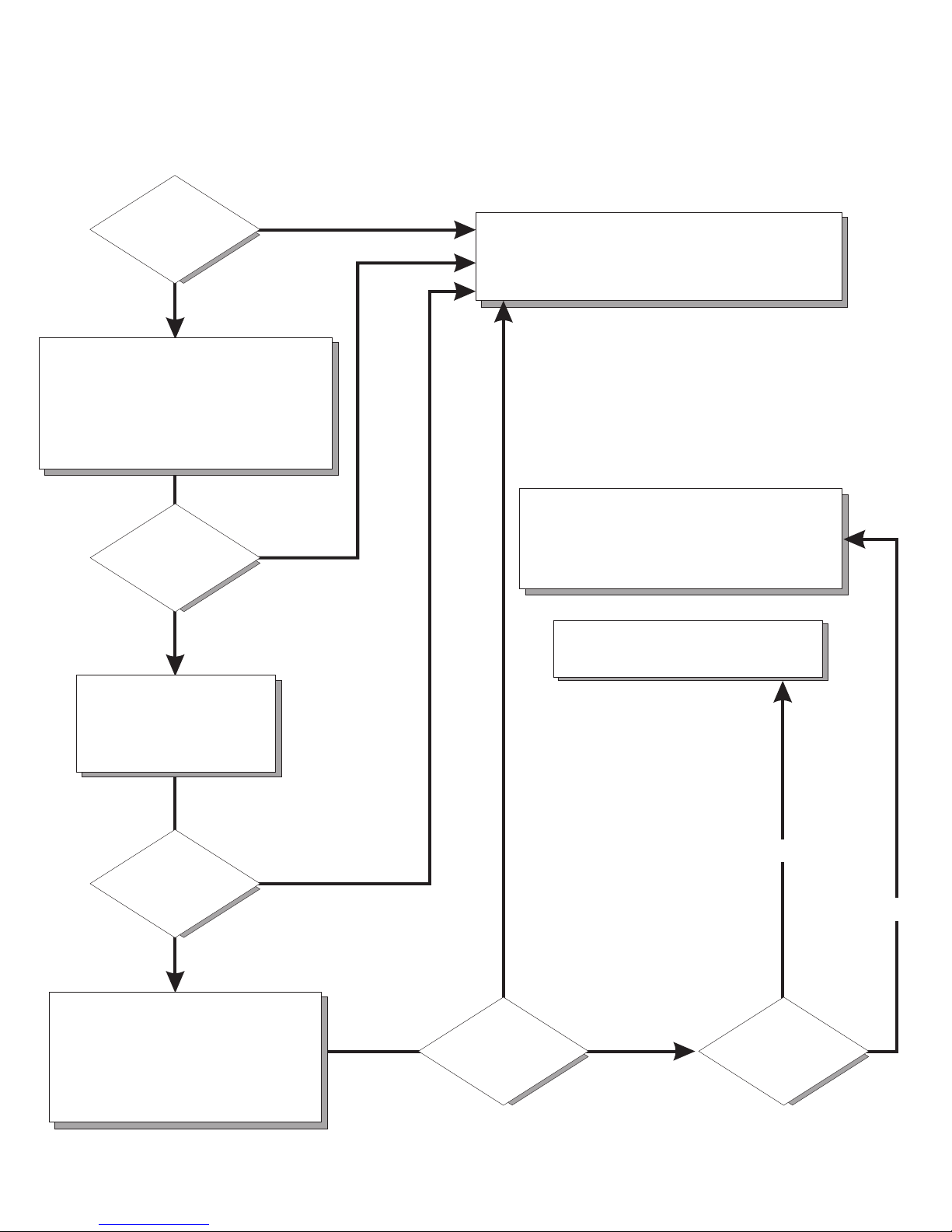
Installation Guide
Set up the computer
Start the computer
Did the computer
start correctly?
Ye s
Do you plan
to use Windows XP or
Red Hat Linux ?
Ye s
No
No
Go to the Computer Support
flow chart on the reverse
side of this page
Install another
operating system
Complete the setup
program
System is ready to use.
Register the computer:
Go to http://www.ibm.com/support/mysupport/
Install options and applications
Page 2
Computer Support
Is the
computer working
properly?
Ye s
No
Check all cables for loose connections
and verify that all optional devices you
installed are on the compatibility matrix.
You can view the atcompatibility matrix
http://www.ibm.com/servers/eserver/
serverproven/compat/us/iserver.html/
Is the
computer working
properly?
Ye s
No
Register your computer. Go to
http://www.ibm.com/support/mysupport/
View information about IBM Support
Line at
http://www.ibm.com/services/sl/products/
or view support telephone numbers at
http://www.ibm.com/planetwide/
View support telephone numbers at
http://www.ibm.com/planetwide/
See the troubleshooting
information that comes with
the computer to determine
the cause of the problem
and the action to take.
Is the
computer working
properly?
Ye s
No
Flash the latest levels of BIOS,
and download the latest level of
diagnostics. You can download
this code at
http://www.ibm.com/support/
Ye s
Is the
computer working
properly?
No
Hardware
Software
Hardware
or Software
problem?
Page 3

IBM IntelliStation M Pro
Ty pe 9229
Installation Guide
Page 4

Note:
Before using this information and the product it supports, read the general information in Appendix B, “Notices,” on page 51, and
the Warranty and Support Information documentation on the IBM IntelliStation Documentation CD.
First Edition (October 2006)
© Copyright International Business Machines Corporation 2006. All rights reserved.
US Government Users Restricted Rights – Use, duplication or disclosure restricted by GSA ADP Schedule Contract
with IBM Corp.
Page 5

Contents
Safety . . . . . . . . . . . . . . . . . . . . . . . . . . . .v
Chapter 1. Introduction . . . . . . . . . . . . . . . . . . . . . .1
The IntelliStation Documentation CD . . . . . . . . . . . . . . . . .3
Hardware and software requirements . . . . . . . . . . . . . . . .3
Using the Documentation Browser . . . . . . . . . . . . . . . . .3
Related documentation . . . . . . . . . . . . . . . . . . . . . .4
Notices and statements in this document . . . . . . . . . . . . . . . .5
Inventory checklist . . . . . . . . . . . . . . . . . . . . . . . .6
Selecting a location for the computer . . . . . . . . . . . . . . . . .6
Arranging the workspace . . . . . . . . . . . . . . . . . . . . . .6
Comfort . . . . . . . . . . . . . . . . . . . . . . . . . . .6
Glare and lighting . . . . . . . . . . . . . . . . . . . . . . .6
Air circulation . . . . . . . . . . . . . . . . . . . . . . . . .7
Electrical outlets and cable lengths . . . . . . . . . . . . . . . . .7
Features and specifications . . . . . . . . . . . . . . . . . . . . .8
Controls, LEDs, and connectors . . . . . . . . . . . . . . . . . . .9
Chapter 2. Cabling and starting the computer . . . . . . . . . . . .11
Cabling the computer . . . . . . . . . . . . . . . . . . . . . .11
Turning on the computer . . . . . . . . . . . . . . . . . . . . .11
Running the operating-system setup program . . . . . . . . . . . . .12
Turning off the computer . . . . . . . . . . . . . . . . . . . . .12
Chapter 3. Configuring the computer . . . . . . . . . . . . . . . .15
Viewing the license agreement . . . . . . . . . . . . . . . . . . .15
Using the built-in configuration programs . . . . . . . . . . . . . . .15
Starting the Configuration/Setup Utility program . . . . . . . . . . . .16
Using the Boot Menu program . . . . . . . . . . . . . . . . . .16
Enabling the Broadcom NetXtreme Gigabit Ethernet Boot Agent . . . . . .16
Configuring the Broadcom NetXtreme Gigabit Ethernet controller . . . . .17
Using the LSI Logic Configuration Utility program . . . . . . . . . . . .17
Chapter 4. Completing the installation . . . . . . . . . . . . . . .19
Recording important numbers . . . . . . . . . . . . . . . . . . .19
Registering the computer . . . . . . . . . . . . . . . . . . . . .19
Creating an emergency recovery-repair diskette in Windows . . . . . . . .20
Creating an IBM Enhanced Diagnostics diskette or CD in Windows . . . . .21
Chapter 5. Solving problems . . . . . . . . . . . . . . . . . . .23
Diagnostic tools overview . . . . . . . . . . . . . . . . . . . . .23
Power-on self-test (POST) . . . . . . . . . . . . . . . . . . . . .24
POST beep codes . . . . . . . . . . . . . . . . . . . . . .24
POST error codes . . . . . . . . . . . . . . . . . . . . . . .24
Troubleshooting tables . . . . . . . . . . . . . . . . . . . . . .36
CD or DVD drive problems . . . . . . . . . . . . . . . . . . .37
Diskette drive problems . . . . . . . . . . . . . . . . . . . . .38
General problems . . . . . . . . . . . . . . . . . . . . . . .39
Hard disk drive problems . . . . . . . . . . . . . . . . . . . .39
Intermittent problems . . . . . . . . . . . . . . . . . . . . . .40
Keyboard, mouse, or pointing-device problems . . . . . . . . . . . .40
Memory problems . . . . . . . . . . . . . . . . . . . . . . .41
Microprocessor problems . . . . . . . . . . . . . . . . . . . .41
© Copyright IBM Corp. 2006 iii
Page 6

Monitor or video problems . . . . . . . . . . . . . . . . . . . .41
Power problems . . . . . . . . . . . . . . . . . . . . . . .44
Serial port problems . . . . . . . . . . . . . . . . . . . . . .45
Software problems . . . . . . . . . . . . . . . . . . . . . .45
Universal Serial Bus device problems . . . . . . . . . . . . . . .46
System-board error LEDs . . . . . . . . . . . . . . . . . . . . .47
Appendix A. Getting help and technical assistance . . . . . . . . . .49
Before you call . . . . . . . . . . . . . . . . . . . . . . . . .49
Using the documentation . . . . . . . . . . . . . . . . . . . . .49
Getting help and information from the World Wide Web . . . . . . . . . .49
Software service and support . . . . . . . . . . . . . . . . . . .50
Hardware service and support . . . . . . . . . . . . . . . . . . .50
IBM Taiwan product service . . . . . . . . . . . . . . . . . . . .50
Appendix B. Notices . . . . . . . . . . . . . . . . . . . . . .51
Trademarks . . . . . . . . . . . . . . . . . . . . . . . . . .52
Important notes . . . . . . . . . . . . . . . . . . . . . . . . .52
Product recycling and disposal . . . . . . . . . . . . . . . . . . .53
Battery return program . . . . . . . . . . . . . . . . . . . . . .54
Electronic emission notices (Class B) . . . . . . . . . . . . . . . .55
Federal Communications Commission (FCC) statement . . . . . . . . .55
Industry Canada Class B emission compliance statement . . . . . . . .56
Avis de conformité à la réglementation d’Industrie Canada . . . . . . . .56
European Union EMC Directive conformance statement . . . . . . . . .56
Japanese Voluntary Control Council for Interference (VCCI) statement . . .56
Index . . . . . . . . . . . . . . . . . . . . . . . . . . . .57
iv IBM IntelliStation M Pro Type 9229: Installation Guide
Page 7

Safety
Before installing this product, read the Safety Information.
Antes de instalar este produto, leia as Informações de Segurança.
Pred instalací tohoto produktu si prectete prírucku bezpecnostních instrukcí.
Læs sikkerhedsforskrifterne, før du installerer dette produkt.
Lees voordat u dit product installeert eerst de veiligheidsvoorschriften.
Ennen kuin asennat tämän tuotteen, lue turvaohjeet kohdasta Safety Information.
Avant d’installer ce produit, lisez les consignes de sécurité.
Vor der Installation dieses Produkts die Sicherheitshinweise lesen.
Prima di installare questo prodotto, leggere le Informazioni sulla Sicurezza.
Les sikkerhetsinformasjonen (Safety Information) før du installerer dette produktet.
Antes de instalar este produto, leia as Informações sobre Segurança.
Antes de instalar este producto, lea la información de seguridad.
Läs säkerhetsinformationen innan du installerar den här produkten.
© Copyright IBM Corp. 2006 v
Page 8

Statement 1:
DANGER
Electrical
current from power, telephone, and communication cables is
hazardous.
To avoid a shock hazard:
v Do not connect or disconnect any cables or perform installation,
maintenance, or reconfiguration of this product during an electrical
storm.
v Connect all power cords to a properly wired and grounded electrical
outlet.
v Connect to properly wired outlets any equipment that will be attached to
this product.
v When possible, use one hand only to connect or disconnect signal
cables.
v Never turn on any equipment when there is evidence of fire, water, or
structural damage.
v Disconnect the attached power cords, telecommunications systems,
networks, and modems before you open the device covers, unless
instructed otherwise in the installation and configuration procedures.
v Connect and disconnect cables as described in the following table when
installing, moving, or opening covers on this product or attached
devices.
To Connect: To Disconnect:
1. Turn everything OFF.
2. First, attach all cables to devices.
3. Attach signal cables to connectors.
4. Attach power cords to outlet.
1. Turn everything OFF.
2. First, remove power cords from outlet.
3. Remove signal cables from connectors.
4. Remove all cables from devices.
5. Turn device ON.
vi IBM IntelliStation M Pro Type 9229: Installation Guide
Page 9

Statement 2:
CAUTION:
When replacing the lithium battery, use only IBM
®
Part Number 33F8354 or an
equivalent type battery recommended by the manufacturer. If your system has
a module containing a lithium battery, replace it only with the same module
type made by the same manufacturer. The battery contains lithium and can
explode if not properly used, handled, or disposed of.
Do not:
v Throw or immerse into water
v Heat to more than 100°C (212°F)
v Repair or disassemble
Dispose
Statement 3:
of the battery as required by local ordinances or regulations.
CAUTION:
When laser products (such as CD-ROMs, DVD drives, fiber optic devices, or
transmitters) are installed, note the following:
v Do not remove the covers. Removing the covers of the laser product could
result in exposure to hazardous laser radiation. There are no serviceable
parts inside the device.
v Use of controls or adjustments or performance of procedures other than
those specified herein might result in hazardous radiation exposure.
DANGER
Some
diode. Note the following.
Laser radiation when open. Do not stare into the beam, do not view directly
with optical instruments, and avoid direct exposure to the beam.
laser products contain an embedded Class 3A or Class 3B laser
Safety vii
Page 10

Statement 4:
≥ 18 kg (39.7 lb) ≥ 32 kg (70.5 lb) ≥ 55 kg (121.2 lb)
CAUTION:
Use safe practices when lifting.
Statement 5:
CAUTION:
The power control button on the device and the power switch on the power
supply do not turn off the electrical current supplied to the device. The device
also might have more than one power cord. To remove all electrical current
from the device, ensure that all power cords are disconnected from the power
source.
1 2
viii IBM IntelliStation M Pro Type 9229: Installation Guide
Page 11

Statement 8:
CAUTION:
Never remove the cover on a power supply or any part that has the following
label attached.
Hazardous voltage, current, and energy levels are present inside any
component that has this label attached. There are no serviceable parts inside
these components. If you suspect a problem with one of these parts, contact
a service technician.
Statement 26:
CAUTION:
Do not place any object on top of rack-mounted devices.
Safety ix
Page 12

Statement 28:
CAUTION:
The battery is a lithium ion battery. To avoid possible explosion, do not burn
the battery. Exchange it only with the IBM-approved part. Recycle or discard
the battery as instructed by local regulations. In the United States, IBM has a
process for collection of this battery. For information, call 1-800-426-4333.
Have the IBM part number for the battery unit available when you call.
Important:
All caution and danger statements in this documentation begin with a
number. This number is used to cross reference an English caution or
danger statement with translated versions of the caution or danger
statement in the IBM Safety Information document.
For example, if a caution statement begins with a number 1,
translations for that caution statement appear in the IBM Safety
Information document under statement 1.
Important:
Be sure to read all caution and danger statements in this
documentation before performing the instructions. Read any additional
safety information that comes with your server or optional device before
you install the device.
This computer is suitable for use on an IT power distribution system,
whose maximum phase to phase voltage is 240 V under any
distribution fault condition.
x IBM IntelliStation M Pro Type 9229: Installation Guide
Page 13

Chapter 1. Introduction
This Installation Guide contains instructions for setting up the IBM
Pro Type 9229 computer. This document contains information about:
v Setting up and cabling the computer
v Starting and configuring the computer
v Setting up the operating system
firmware and documentation updates are available, you can download them from
If
http://www.ibm.com/support/. The computer might have features that are not
described in the documentation that comes with the computer, and the
documentation might be updated occasionally to include information about those
features, or technical updates might be available to provide additional information
that is not included in the computer documentation. To check for updates, go to
http://www.ibm.com/support/. For firmware updates, click Downloads and drivers.
For documentation updates, under Search technical support, type 9229 and click
Search.
Note: Changes are made periodically to the IBM Web site. Procedures for locating
firmware and documentation might vary slightly from what is described in this
document.
®
IntelliStation
®
M
Packaged with this Installation Guide is the Device Drivers CD, which contains
device drivers and hardware-specific support software.
The IBM IntelliStation Documentation CD is also included. This CD provides
detailed information about the computer (see “The IntelliStation Documentation CD”
on page 3 for more information).
You can obtain up-to-date information about the computer and other IBM products
at http://www.ibm.com/intellistation/.
The computer model and serial number are on labels on the bottom of the
computer and on the lower-right side of the bezel, as shown in the following
illustration. You will need this information when you register the computer with IBM.
© Copyright IBM Corp. 2006 1
Page 14

Model number
and serial number
Important: The computer keys cannot be duplicated by a locksmith. If you lose
them, order replacement keys from the key manufacturer. The key serial number
and the telephone number of the manufacturer are on a tag that is attached to the
keys.
You can rack-mount the computer on a shelf, but do not rack-mount it on rails.
The computer comes with Microsoft
Enterprise Linux
®
Workstation preinstalled (depending on the model).
Windows
®
XP Professional or Red Hat
®
To install a different operating system, follow the instructions in the documentation
that comes with the operating system and any updates. Then, follow the instructions
in the readme file on the Device Drivers CD to install the support software.
Note: If you install another operating system, you might need additional software or
device drivers. Some preinstalled device drivers are available on the Device
Drivers CD. If you experience problems with the device drivers that you
install from this CD, you can obtain the latest device drivers from
http://www.ibm.com/support/.
Before you install any operating system, be sure to obtain the latest updates for the
operating system. Contact the operating-system manufacturer or, if applicable,
check the manufacturer’s Web site to obtain the updates.
Additional information about operating systems is posted periodically at
http://www.ibm.com/support/.
2 IBM IntelliStation M Pro Type 9229: Installation Guide
Page 15

The IntelliStation Documentation CD
The IBM IntelliStation Documentation CD contains documentation for the computer
in Portable Document Format (PDF) and includes the IBM Documentation Browser
to help you find information quickly.
Hardware and software requirements
The IBM IntelliStation Documentation CD requires the following minimum hardware
and software:
®
v Microsoft Windows NT
4.0 (with Service Pack 3 or later), Windows 2000, or
Red Hat Linux.
v 100 MHz microprocessor.
v 32 MB of RAM.
v Adobe Acrobat Reader 3.0 (or later) or xpdf, which comes with Linux operating
systems. Acrobat Reader software is included on the CD, and you can install it
when you run the Documentation Browser.
Using the Documentation Browser
Use the Documentation Browser to browse the contents of the CD, read brief
descriptions of the documents, and view documents, using Adobe Acrobat Reader
or xpdf. The Documentation Browser automatically detects the regional settings in
use in the computer and displays the information in the language for that region (if
available). If a document is not available in the language for that region, the
English-language version is displayed.
Use one of the following procedures to start the Documentation Browser:
v If Autostart is enabled, insert the documentation CD into the CD drive. The
Documentation Browser starts automatically.
v If Autostart is disabled or is not enabled for all users, use one of the following
procedures:
– If you are using a Windows operating system, insert the documentation CD
into the CD drive, and click Start --> Run. In the Open field, type
e:\win32.bat
where e is the drive letter of the CD drive, and click OK.
– If you are using Red Hat Linux, insert the CD into the CD drive; then, run the
following command from the /mnt/cdrom directory:
sh runlinux.sh
Select your computer from the Product menu. The Available Topics list displays
all the documents for the computer. Some documents might be in folders. A plus
sign (+) indicates each folder or document that has additional documents under it.
Click the plus sign to display the additional documents.
When you select a document, a description of the document is displayed under
Topic Description. To select more than one document, press and hold the Ctrl key
while you select the documents. Click View Book to view the selected document or
documents in Acrobat Reader or xpdf. If you selected more than one document, all
the selected documents are opened in Acrobat Reader or xpdf.
To search all the documents, type a word or word string in the Search field and
click Search. The documents in which the word or word string appears are listed in
Chapter 1. Introduction 3
Page 16

order of the most occurrences. Click a document to view it, and press Crtl+F to use
the Acrobat search function or press Alt+F to use the xpdf search function within the
document.
Click Help for detailed information about using the Documentation Browser.
Related documentation
This Installation Guide provides general information about the computer, including
information about features, how to configure the computer, setup instructions,
installation instructions, and how to get help. In addition to this Installation Guide,
the following documentation comes with the computer:
v User’s Guide
This document is in Portable Document Format (PDF) on the IBM IntelliStation
Documentation CD. It contains general information about the computer, how to
install optional devices, and how to use and configure the functions of the
computer.
v Problem Determination and Service Guide
This document is in PDF on the IBM IntelliStation Documentation CD and at
http://www.ibm.com/support/. This document contains information to help you
solve problems yourself, and it contains information for service technicians.
v Safety Information
This document is in PDF on the IBM IntelliStation Documentation CD. It contains
translated caution and danger statements. Each caution and danger statement
that appears in the documentation has a number that you can use to locate the
corresponding statement in your language in the Safety Information document.
v Warranty and Support Information
This document is in PDF on the IBM IntelliStation Documentation CD. It contains
information about the terms of the warranty and getting services and assistance.
4 IBM IntelliStation M Pro Type 9229: Installation Guide
Page 17

v Readme files on the Device Drivers CD
Several readme files on the CD contain information about preinstalled device
drivers. Other readme files on the CD contain information about the various
adapters and devices that might be installed in or attached to the computer.
v IBM IntelliStation Documentation CD
Depending on the computer model, additional documentation might be included
on the IBM IntelliStation Documentation CD.
Notices and statements in this document
The caution and danger statements in this document are also in the multilingual
Safety Information document, which is on the IBM IntelliStation Documentation CD.
Each statement is numbered for reference to the corresponding statement in the
Safety Information document.
The following notices and statements are used in this document:
v Note: These notices provide important tips, guidance, or advice.
v Important: These notices provide information that might help you avoid
inconvenient or problem situations.
v Attention: These notices indicate possible damage to programs, devices, or
data. An attention notice is placed just before the instruction or situation in which
damage could occur.
v Caution: These statements indicate situations that can be potentially hazardous
to you. A caution statement is placed just before the description of a potentially
hazardous procedure step or situation.
v Danger: These statements indicate situations that can be potentially lethal or
extremely hazardous to you. A danger statement is placed just before the
description of a potentially lethal or extremely hazardous procedure step or
situation.
Chapter 1. Introduction 5
Page 18

Inventory checklist
Take an inventory of items as you unpack them, to make sure that you have all of
the components. The following items come with the IBM IntelliStation M Pro Type
9229 computer:
v One Universal Serial Bus (USB) keyboard
v One USB mouse
v One power cord
v One Device Drivers CD
v One IBM IntelliStation Documentation CD
v This Installation Guide
v One pigtail cable or digital-to-analog converter (depending on the model)
If any items are missing or damaged, contact your place of purchase.
Selecting a location for the computer
Make sure that you have an adequate number of properly grounded electrical
outlets for the computer, monitor, and any other devices. Select a location for the
computer where it will remain dry. Leave approximately 50 mm (2 in.) of space
around the computer for proper air circulation. For information about arranging the
computer and ease-of-use, see the following sections.
Arranging the workspace
To get the most from the computer, arrange the equipment that you use and your
work area to suit your needs and the kind of work that you do. Your comfort is of
foremost importance, but light sources, air circulation, and the location of electrical
outlets can also affect the way you arrange your workspace.
Comfort
The following guidelines will help you decide what working position suits you best.
Choose a comfortable chair to reduce fatigue from sitting in the same position for
long periods. The backrest and seat should adjust independently and provide good
support. The seat should have a curved front to relieve pressure on the thighs.
Adjust the seat so that your thighs are parallel to the floor and your feet are either
flat on the floor or on a footrest.
When you use the keyboard, keep your forearms parallel to the floor and your
wrists in a neutral, comfortable position. Try to keep a light touch on the keyboard,
and your hands and fingers relaxed. Change the angle of the keyboard for
maximum comfort by adjusting the position of the keyboard feet.
Adjust the monitor so that the top of the screen is at, or slightly below, eye level.
Place the monitor at a comfortable viewing distance, usually 51 to 61 cm (20 to 24
in.), and position it so that you can view it without having to twist your body.
Glare and lighting
Position the monitor to minimize glare and reflections from overhead lights,
windows, and other light sources. Place the monitor at right angles to light sources
whenever possible. Reduce overhead lighting, if necessary, by turning off lights or
using lower wattage bulbs. If you install the monitor near a window, use curtains or
6 IBM IntelliStation M Pro Type 9229: Installation Guide
Page 19

blinds to block the sunlight. You might have to adjust the brightness and contrast
controls on the monitor as the lighting changes throughout the day.
Where it is impossible to avoid reflections or to adjust the lighting, place an
antiglare filter over the screen. However, these filters might affect the clarity of the
screen image; try them only after you have exhausted other methods of reducing
glare.
Dust compounds problems that are associated with glare. Clean the monitor screen
periodically, using a soft cloth moistened with a nonabrasive, liquid glass cleaner.
Air circulation
The computer and monitor produce heat. The computer pulls in fresh air and forces
out hot air. The monitor lets hot air escape through vents. Blocking the air vents can
cause overheating, possibly resulting in malfunction or damage. Place the computer
and monitor so that nothing blocks the air vents; usually 50 mm (2 in.) of air space
is sufficient. Also, make sure that the vented air is not blowing on someone else.
Electrical outlets and cable lengths
The location of electrical outlets and the length of device power cords and cables
might determine the placement of the computer.
When arranging your work space:
v Avoid the use of extension cords. Whenever possible, connect the computer
power cord directly into an electrical outlet.
v Keep power cords and cables neatly routed away from walkways and other areas
where they might be accidentally dislodged.
For more information about power cords, see the Problem Determination and
Service Guide.
Chapter 1. Introduction 7
Page 20

Features and specifications
The following information is a summary of the features and specifications of the
computer. Depending on the computer model, some features might not be available,
or some specifications might not apply. Use the Configuration/Setup Utility program
to determine the type and speed of the microprocessor.
Table 1. Features and specifications
Microprocessor:
v Supports one Intel
®
Core
™
2 Duo
microprocessor
v 2 or 4 MB Level-2 cache
v 1066 MHz front-side bus (FSB)
Memory:
v Minimum: 512 MB
v Maximum: 8 GB
v Type: PC2-5300, dual-data-rate 2
(DDR2) unbuffered error correcting
code (ECC)
v Connectors: four dual inline memory
module (DIMM) connectors
Internal drives:
v Hard disk drive: SATA or SAS
v One of the following drives:
– DVD/CD-RW combo: IDE
– CD-RW: IDE
Expansion
bays:
v One slim-high 3.5-inch external drive
bay (optional diskette drive)
v Tw o half-high 5.25-inch bays (optical
drive installed in one bay)
v Three slim-high 3.5-inch internal drive
bays (one hard disk drive installed)
expansion slots:
PCI
v One PCI Express x8 (x4 electrical)
slot
v Tw o PCI Express x16 slots (one x16
or two x8)
v One PCI 32-bit/33 MHz slot
Note: When you install the NVIDIA
Quadro FX 3500 video adapter in the
computer, do not set the analog
resolution above 1600 x 1200 @ 60 Hz.
This is the highest resolution supported
for the NVIDIA Quadro FX 3500 video
adapter. In addition, when you use a
cathode ray tube (CRT) type monitor,
the monitor cable must come with a
ferrite suppression on both ends of the
monitor cable.
Integrated functions:
v Broadcom 5752 10/100/1000 Ethernet
controller with RJ-45 Ethernet connector
v Tw o serial connectors
v One parallel connector
v Four-port serial ATA controller
v Tw o IEEE 1394 (FireWire) ports
(four-pin on front, six-pin on rear)
v Eight USB connectors (two on front and
six on rear)
v Keyboard connector
v Mouse connector
v Audio connectors
– Line out (front and rear)
– Mic (front)
– Line in (rear)
v Single-channel IDE controller
adapter: (depending on the model)
Video
v NVIDIA Quadro NVS 285 (DMS-59),
PCI Express x16, with 128 MB DDR2
SDRAM and dual analog connectors,
(or dual digital monitor capability with
the purchase of an additional pigtail
cable)
v NVIDIA Quadro FX 550 (DVI-I), PCI
Express x16, with 128 MB GDDR3s
synchronous dynamic random access
memory (SDRAM) and dual DVI-I
connectors
v NVIDIA Quadro FX 1500 (dual-link
DVI-I), PCI Express x16, with 256 MB
GDDR3 SDRAM and two dual DVI-I
connectors
v NVIDIA Quadro FX 3500 (DVI-I), PCI
Express x16, with 256 MB GDDR3
SDRAM and two dual DVI-I connectors
supply:
Power
One 400-watts (115 - 230 V ac)
Cooling:
v One speed-controlled microprocessor
fan and one power-supply fan
v One power-supply fan
Electrical input:
v Sine-wave input (50 or 60 Hz) required
v Input voltage and frequency ranges
automatically selected
v Input voltage low range:
– Minimum: 90 V ac
– Maximum: 137 V ac
Input voltage high range:
v
– Minimum: 180 V ac
– Maximum: 265 V ac
v Input kilovolt-amperes (kVA) approximately:
– Minimum: 0.10 kVA
– Maximum: 0.37 kVA
output:
Heat
Approximate heat output in British thermal
units (Btu) per hour:
v Minimum configuration: 341 Btu per hour
(100 watts)
v Maximum configuration: 1239 Btu per hour
(363 watts)
Environment:
v Air temperature:
– Computer on: 10° to 35°C (50° to 95°F)
Altitude: 0 to 2134 m (7000 ft)
– Computer off: -40° to +60°C (-40° to
+140°F)
Maximum altitude: 2133 m (7000 ft)
v Humidity (operating and storage): 8% to
80%
Acoustical
noise emissions:
v Sound power, idle: 4.3 bel
v Sound power, operating: 4.8 bel
Size:
v Height: 430 mm (16.9 in.)
v Depth: 445 mm (17.5 in.)
v Width: 178 mm (7.0 in.)
v Weight: 12.5 kg (27.5 lb) to 15.5 kg (34.1
lb) depending upon configuration
8 IBM IntelliStation M Pro Type 9229: Installation Guide
Page 21

Controls, LEDs, and connectors
The following illustration shows the controls, LEDs, and front connectors on the
computer. See “Cabling the computer” on page 11 for an illustration of the
connectors on the rear of the computer.
Power-control button
Power-on LED
System error LED
Hard disk drive
activity LED
CD or DVD drive activity LED
Ethernet
activity LED
CD or DVD
eject button
AC power LED
Power-supply
error LED
Optional diskette drive
activity LED
Optional diskette-eject
button
1
3
9
4
IEEE 1394 (Firewire)
connector
USB connector
USB connector
Microphone connector
Line out connector
CD or DVD drive activity LED
When this LED is lit, it indicates that the CD or DVD drive is in use.
CD or DVD eject button
Press this button to insert a CD or DVD into or remove a CD or DVD from
the CD or DVD drive.
AC power LED
When this green LED is lit, it indicates that the computer is connected to an
ac power source. This LED is on the rear of the computer.
Power-supply error LED
When this amber LED is lit, it indicates that a power-supply error has
occurred. This LED is on the rear of the computer.
Optional diskette drive activity LED
When this LED is lit, it indicates that the diskette drive is in use.
Optional diskette-eject button
Press this button to release a diskette from the diskette drive.
Note: The diskette drive is an optional feature on some models.
Chapter 1. Introduction 9
Page 22

IEEE 1394 (FireWire) connectors
Use these connectors (four-pin on the front and six-pin on the rear) to
connect FireWire devices, such as a digital video camera or an external
hard disk drive.
USB connectors
Use these connectors to connect USB devices to the computer, using
redundant Plug and Play technology.
Microphone connector (pink)
Use this connector to connect a microphone to the computer when you
want to record voices or other sounds on the hard disk. You can also use
this connector (and a microphone) with speech-recognition software.
Line out connector (green)
Use this connector to send audio signals from the computer to external
devices, such as speakers with built-in amplifiers, headphones, a
multimedia keyboard, or the audio line-in jack on a stereo system.
Hard disk drive activity LED
When this LED is lit, it indicates that the hard disk drive is in use.
System-error LED
When this LED is lit, it indicates that a system error has occurred. An LED
on the system board might also be lit to help isolate the error. If the LED on
the system board is not lit, check the error log.
Ethernet activity LED
When this LED is lit, it indicates that there is activity between the computer
and the network. There are two of these LEDs, one on the front and one on
the rear of the computer.
Power-on LED
When this LED is lit, it indicates that the computer is turned on.
Power-control button
Press this button to turn the computer on or off.
10 IBM IntelliStation M Pro Type 9229: Installation Guide
Page 23

Chapter 2. Cabling and starting the computer
This chapter provides information about cabling, starting the computer, and
completing the operating system setup procedure.
Cabling the computer
If the computer cables and connector panel have color-coded connectors, match
the color of each cable end with the color of the connector. For example, match a
blue cable end to a blue connector on the panel, a red cable end to a red
connector, and so on.
Attention: To prevent damage to equipment, connect the power cord last.
The following illustration shows the input/output (I/O) connectors on the rear of the
computer.
Power cord
Depending on the video adapter that is installed in the computer and the monitor
that you are using, you might have to use special video cables that convert signals
or provide an additional connection point for dual-monitor capability. See the User’s
Guide on the IBM IntelliStation Documentation CD and the documentation that
comes with the monitor for additional information.
Turning on the computer
Line in
Line out
Serial
Parallel
Keyboard
Mouse
USBs
NMI
Ethernet
IEEE 1394
(FireWire)
Video
When the computer is connected to an ac power source but is not turned on, the
operating system does not run, and all core logic is shut down; however, the
computer can respond to requests, such as a remote request to turn on the
computer.
© Copyright IBM Corp. 2006 11
Page 24

Notes:
1. Turn on all external devices, such as the monitor, before you turn on the
computer.
2. The power-on LED on the front of the computer is lit when the computer is on
and while it is being turned on.
Approximately 20 seconds after the computer is connected to ac power, the
power-control button becomes active, and you can turn on the computer and start
the operating system by pressing the power-control button. The computer can also
be turned on any of the following ways:
v If a power failure occurs while the computer is turned on, the computer will
restart automatically when power is restored.
v When you connect the computer to power for the first time, the Wake on LAN
feature can turn on the computer. If the computer was previously turned on, it
must be properly turned off for the Wake on LAN feature to turn on the computer.
Running the operating-system setup program
If you are starting the computer for the first time, the setup program runs
automatically when you start the computer. The program prompts you to make
choices or type information. If you need more information than is provided in this
Installation Guide, see the operating-system documentation.
®
Important:
1. After turning on the computer for the first time, you must complete the
operating-system setup procedure before you turn off the computer; otherwise,
unexpected results might occur.
2. The setup program might be slightly different from the one that is described in
the operating-system documentation. Some choices are not available because
they are preset.
3. During the setup procedure, you must indicate that you accept the license
agreement.
4. For Windows operating systems, the registration information is already
displayed in the registration field. If the product ID number is not already
displayed, you must type it. The product ID is on a label that is attached to the
computer.
You will need the following information to complete the setup program in a Windows
operating system:
v The documentation that comes with the computer.
v Network information from your network administrator, if the computer is being
connected to a network.
v The printer model and port, if a printer is attached directly to the computer.
After the setup procedure is completed and the computer restarts, the desktop
opens, and the computer is ready for use.
Turning off the computer
When you turn off the computer and leave it connected to ac power, the computer
can respond to requests, such as a remote request to turn on the computer. To
remove all power from the computer, you must disconnect it from the power source.
12 IBM IntelliStation M Pro Type 9229: Installation Guide
Page 25

Some operating systems require an orderly shutdown before you turn off the
computer. See the operating-system documentation for information about shutting
down the operating system.
Statement 5:
CAUTION:
The power control button on the device and the power switch on the power
supply do not turn off the electrical current supplied to the device. The device
also might have more than one power cord. To remove all electrical current
from the device, ensure that all power cords are disconnected from the power
source.
1 2
The computer can be turned off in any of the following ways:
v Yo u can turn off the computer through the operating system. If this feature is
supported by the operating system, it will turn off the computer after you perform
an orderly shutdown of the operating system.
If you are using the preinstalled Microsoft Windows XP operating system,
complete the following steps to shut down the operating system and turn off the
computer:
1. Save and close all files that you are working with.
2. Close all open applications.
3. Click Start.
4. Click Turn Off Computer; then, click Turn Off to confirm.
If you are using the preinstalled Red Hat Linux operating system, complete the
following steps to shut down the operating system and turn off the computer:
1. Save and close all files that you are working with.
2. Close all open applications.
3. Click Red Hat Linux Main Menu Button → Logout → Shutdown.
4. Click OK to confirm.
v Yo u can press the power-control button on the front of the computer to start an
orderly shutdown of the operating system and turn off the computer, if the
operating system supports this feature.
Note: After you turn off the computer, wait at least 5 seconds before you press
the power-control button to turn on the computer again.
v Yo u can press and hold the power-control button for more than 4 seconds to
cause an immediate shutdown of the computer. You can use this feature to turn
off the computer if the operating system stops functioning.
Chapter 2. Cabling and starting the computer 13
Page 26

14 IBM IntelliStation M Pro Type 9229: Installation Guide
Page 27

Chapter 3. Configuring the computer
This chapter describes how to configure software for the computer.
Viewing the license agreement
The IBM International License Agreement for Non-Warranted Programs is viewable
from the Access IBM folder. Use of the computer signifies acceptance of this
agreement.
To view the license agreement in Windows XP, complete the following steps:
1. From the Windows XP desktop, click Start → All Programs → Access IBM.
2. Select IBM License Agreement.
For Red Hat Linux, when you start the computer, the License Agreement window
opens. To accept the terms of the agreement, click I Agree. You can also view the
license agreement by clicking on the IBM License Agreement icon on the desktop.
Using the built-in configuration programs
The following configuration programs are available to configure the computer:
v Configuration/Setup Utility program
The Configuration/Setup Utility program is part of the basic input/output system
(BIOS). You can use this program to configure serial port assignments, change
interrupt request (IRQ) settings, change the drive startup sequence, set the date
and time, set passwords, and set the chassis-intrusion detector. For more
information about using this utility program, see “Starting the Configuration/Setup
Utility program” on page 16.
v Boot Menu program
The Boot Menu program is part of the BIOS. Use it to temporarily assign a
device to be first in the startup sequence, Override the startup sequence that is
set in the Configuration/Setup Utility program and for information about how to
start the Boot Menu, see “Using the Boot Menu program” on page 16.
v Broadcom NetXtreme Gigabit Ethernet Boot Agent
The Broadcom NetXtreme Gigabit Ethernet Boot Agent is part of the BIOS. You
can use it to configure the network as a startable device, and you can customize
where the network startup option occurs in the startup sequence. Enable and
disable the Broadcom NetXtreme Gigabit Ethernet Boot Agent from the
Configuration/Setup Utility program. For information, see “Enabling the Broadcom
NetXtreme Gigabit Ethernet Boot Agent” on page 16.
v Broadcom NetXtreme Gigabit Ethernet controller configuration
To configure the integrated Gigabit Ethernet controller, see “Configuring the
Broadcom NetXtreme Gigabit Ethernet controller” on page 17.
v LSI Logic Configuration Utility program
Use the LSI Logic Configuration Utility program to configure the integrated
SAS/SATA controller with RAID capabilities and the devices that are attached to
it. For information about using this program, see “Using the LSI Logic
Configuration Utility program” on page 17.
the User’s Guide on the IBM IntelliStation Documentation CD for detailed
See
instructions for using the configuration programs.
© Copyright IBM Corp. 2006 15
Page 28

The following sections provide utility program instructions for starting the
Configuration Utility programs.
Starting the Configuration/Setup Utility program
The Configuration/Setup Utility program is a menu-driven utility that is part of the
BIOS. Use it to:
v Configure serial port assignments
v Change the startup sequence
v Enable USB keyboard and mouse support
v Resolve configuration conflicts
v Set the date and time
v Set passwords
start the Configuration/Setup Utility program, complete the following steps:
To
1. Turn on the computer and watch the monitor screen. If the computer is already
on when you start this procedure, you must shut down the operating system,
turn off the computer, wait a few seconds until all in-use LEDs are turned off,
and restart the computer.
2. When the message Press F1 for Configuration/Setup, Press F12 for Boot
Menu is displayed, press F1. (This prompt is displayed on the screen for only a
few seconds. You must press F1 quickly.) If you have set both a power-on
password and an administrator password, you must type the administrator
password to access the full Configuration/Setup Utility menu. If you do not type
the administrator password, a limited Configuration/Setup Utility menu is
available.
3. Follow the instructions on the screen.
Using the Boot Menu program
The Boot Menu program is a built-in, menu-driven configuration program that you
can use to temporarily redefine the first startup device without changing settings in
the Configuration/Setup Utility program.
To use the Boot Menu program complete the following steps:
1. Turn off the computer.
2. Restart the computer.
3. Press F12.
4. Select the startup device.
next time the computer is started, it returns to the startup sequence that is set
The
in the Configuration/Setup Utility program.
Enabling the Broadcom NetXtreme Gigabit Ethernet Boot Agent
The Broadcom NetXtreme Gigabit Ethernet Boot Agent is part of the BIOS. You can
use it to configure the network as a startable device, and you can customize where
the network startup option occurs in the startup sequence. Enable and disable the
Broadcom NetXtreme Gigabit Ethernet Boot Agent from the Configuration/Setup
Utility program.
To enable the Broadcom NetXtreme Gigabit Ethernet boot agent, complete the
following steps:
16 IBM IntelliStation M Pro Type 9229: Installation Guide
Page 29

1. From the Configuration/Setup Utility main menu, select Devices and I/O Ports
and press Enter.
2. Select Planar Ethernet and use the Right Arrow (→) key to set it to Enabled.
3. Set the Network-Planar device as the first startup device under the Startup
Option → Startup Sequence Options menu choice in the Configuration/Setup
Utility program.
4. Under the Startup Option menu choice, select Planar Ethernet PXE/DHCP
and use the Right Arrow key (→) to set it to Planar Ethernet.
5. Select Save Settings and press Enter.
Configuring the Broadcom NetXtreme Gigabit Ethernet controller
The Ethernet controller is integrated on the system board. It provides an interface
for connecting to a 10 Mbps, 100 Mbps, or 1 Gbps network and provides full duplex
(FDX) capability, which enables simultaneous transmission and reception of data on
the network. If the Ethernet port in the computer supports auto-negotiation, the
controller detects the data-transfer rate (10BASE-T, 100BASE-TX, or 1000BASE-T)
and duplex mode (full-duplex or half-duplex) of the network and automatically
operates at that rate and mode.
You do not have to set any jumpers or configure the controller. However, you must
install a device driver to enable the operating system to address the controller. For
device drivers and information about configuring the Gigabit Ethernet controller, see
http://www.ibm.com/support/.
Using the LSI Logic Configuration Utility program
Use the LSI Logic Configuration Utility program Manager to configure and manage
redundant array of independent disks (RAID) arrays. Be sure to use these programs
as described in this document.
v Use the LSI Logic Configuration Utility program to:
– Perform a low-level format on a SAS/SATA hard disk drive
– Set SAS/SATA protocol parameters
addition, an LSI command-line configuration program is available from
In
http://www.ibm.com/support/.
Consider the following information when using the LSI Logic Configuration Utility
program to configure and manage arrays:
v The integrated SAS/SATA controller with RAID capabilities supports the following
features:
– Integrated Mirroring (IM) with hot-spare support (also known as RAID 1)
Use this option to create an integrated array of two disks plus an optional hot
spare. All data on the primary disk can be migrated.
– Integrated Mirroring Enhanced (IME) with hot-spare support (also known as
RAID 1E)
Use this option to create an integrated mirror enhanced array of three to eight
disks, including an optional hot spare.
– Integrated Striping (IS) (also known as RAID 0)
Use this option to create an integrated striping array of two to eight disks. All
data on the array disk will be deleted.
Chapter 3. Configuring the computer 17
Page 30

v Hard disk drive capacities affect how you create arrays. The drives in an array
can have different capacities, but the RAID controller treats them as if they all
have the capacity of the smallest hard disk drive.
v If you use an integrated SAS/SATA controller with RAID capabilities to configure
a RAID 1 (mirrored) array after you have installed the operating system, you will
lose access to any data or applications that were previously stored on the
secondary drive of the mirrored pair.
v If you install a different type of RAID controller, see the documentation that
comes with the controller for information about viewing and changing SAS/SATA
settings for attached devices.
start the LSI Logic Configuration Utility program, complete the following steps:
To
1. Turn on the computer.
2. When the message <<< Press <CTRL><C> to start LSI Logic Configuration
Utility >>> is displayed, press Ctrl+C.
3. Use the arrow keys to select a controller (channel) from the list of adapters;
then, press Enter.
4. To change the settings of the selected items, follow the instructions on the
screen. If you select Raid Properties, SAS Topology, or Advanced Adapter
Properties additional screens are displayed.
the User’s Guide on the IBM IntelliStation Documentation CD for more
See
information about the LSI Logic Configuration Utility program.
18 IBM IntelliStation M Pro Type 9229: Installation Guide
Page 31

Chapter 4. Completing the installation
This chapter provides information to help you register the computer, record
important information, and back up the application programs.
Recording important numbers
Record information about the computer in the following table. You will need this
information when you register the computer with IBM.
Product name IBM IntelliStation M Pro
Machine type 9229
Model number _____________________________________________
Serial number _____________________________________________
Key serial number _____________________________________________
Key manufacturer _____________________________________________
Key phone number _____________________________________________
Registering the computer
Registering the computer helps IBM provide better service to you. When IBM
receives the registration information, the information is placed into a central
technical support database. If you need technical assistance, the technical-support
representative will have information about the computer. In addition, comments
about the computer are reviewed by a team dedicated to customer satisfaction and
are taken into consideration in making improvements to IBM computers.
Use one of the following procedures to register the computer in Windows:
v From the Windows XP desktop, click Start → All Programs → IBM Registration
and then follow the instructions. If you do not have access to the Internet, you
can use the registration program that starts through the IBM Registration folder to
print the registration information and provide IBM with a mailing address for
future technical assistance.
v Register the computer at http://www.ibm.com/support/mysupport/.
For Red Hat Linux, click the Register PC icon on the desktop to register the
computer on the World Wide Web.
© Copyright IBM Corp. 2006 19
Page 32

Creating an emergency recovery-repair diskette in Windows
Note: To create and use a diskette, you must add a diskette drive to the computer.
To enable a USB diskette drive to work, you must disable the legacy diskette
drive function in the Configuration/Setup Utility program (click Startup
Sequence Options → Legacy USB Support).
At the earliest possible opportunity, create a recovery-repair diskette and an IBM
Enhanced Diagnostics diskette, and store them in a safe place.
In the unlikely event that the computer becomes unusable, you can use the
recovery-repair diskette to access the Product Recovery program, which runs
independently of the operating system and reinstalls the operating system and
preinstalled software. For information about using the recovery-repair diskette, see
the Problem Determination and Service Guide on the IBM IntelliStation
Documentation CD.
The Product Recovery program is on a hidden partition on the hard disk. If you are
using FDISK, Disk Management, or another utility to reformat the hard disk, you
might see the partition where the Product Recovery program is stored. Do not
delete this partition; otherwise, the Product Recovery program will be lost.
If the hard disk drive on which the Product Recovery program is stored becomes
damaged or if you replace the hard disk drive, contact IBM to order the IBM
Product Recovery CD to recover the preinstalled operating system, application
programs, and device drivers. See Appendix A, “Getting help and technical
assistance,” on page 49 for details.
In Windows, you can create a recovery-repair diskette from the c:\ibmtools directory
or from the Product Recovery program partition.
To create a recovery-repair diskette from the c:\ibmtools directory, complete the
following steps:
1. Start the computer and operating system.
2. Use Windows Explorer to display the directory structure of the hard disk.
3. Open the c:\ibmtools folder.
4. Double-click rrdisk.bat and follow the instructions on the screen.
To create a recovery-repair diskette from the Product Recovery partition program on
the hard disk, complete the following steps:
1. Shut down the operating system and turn off the computer.
2. Wait for at least 5 seconds; then, press and hold the F11 key while you restart
the computer. When a menu is displayed, release the F11 key.
3. Use one of the following procedures:
v If a menu is displayed in which you can select an operating system, use the
arrow keys to select the operating system that is currently installed, press
Enter, and then continue with the next step.
v If an operating-system menu is not displayed, continue with the next step.
From the Product Recovery Main menu, use the arrow keys to select System
4.
utilities, and then press Enter.
5. Use the arrow keys to select Create a Recovery Repair diskette, and then
press Enter.
20 IBM IntelliStation M Pro Type 9229: Installation Guide
Page 33

6. Follow the instructions on the screen.
“Creating an IBM Enhanced Diagnostics diskette or CD in Windows” for
See
information about how to create an IBM Enhanced Diagnostics diskette.
Creating an IBM Enhanced Diagnostics diskette or CD in Windows
Note: To create and use a diskette or CD, a diskette, CD-RW, or DVD/CD-RW
combo drive must be installed in the computer. To enable a USB diskette
drive to work, you must disable the legacy diskette drive function in the
Configuration/Setup Utility program (click Startup Sequence Options →
Legacy USB Support).
The IBM Enhanced Diagnostics diskette is a self-starting diagnostic diskette that is
used to test hardware components on the computer. You can create an IBM
Enhanced Diagnostics diskette from the Product Recovery program. You can create
an IBM Enhanced Diagnostics CD from the World Wide Web. Use one of the
following methods to create a startable IBM Enhanced Diagnostics diskette.
To create an IBM Enhanced Diagnostics diskette from the Product Recovery
program partition, complete the following steps:
1. Restart the computer.
2. When the message, To start the Product Recovery Program, Press F11 is
displayed, quickly press F11.
3. Select System utilities.
4. Select Create IBM Enhanced Diagnostics Diskette.
5. Follow the instructions on the screen.
download the latest CD image of the IBM Enhanced Diagnostics from the Web
To
and create a startable IBM Enhanced Diagnostics CD, complete the following steps.
1. Go to http://www.ibm.com/support/.
2. Click Search technical support.
3. In the Enter keyword(s) field, type diagnostics 9229, and click Search.
4. From the ″Search results″ page, click the Enhanced Diagnostics item for the
computer.
5. On the next page, click the CD image file for the Enhanced Diagnostics code
and download it using a writeable optional device (CD-RW or DVD/CD-RW
combo drive).
For more information about using the IBM Enhanced Diagnostics program, see the
Problem Determination and Service Guide on the IBM IntelliStation Documentation
CD.
Chapter 4. Completing the installation 21
Page 34

22 IBM IntelliStation M Pro Type 9229: Installation Guide
Page 35

Chapter 5. Solving problems
This chapter provides basic troubleshooting information to help you diagnose and
solve some problems that might occur while you are setting up your computer.
If you cannot locate and correct a problem by using the information in this chapter,
see Appendix A, “Getting help and technical assistance,” on page 49 and the
Problem Determination and Service Guide on the IBM IntelliStation Documentation
CD.
Diagnostic tools overview
The following tools are available to help you diagnose and solve hardware-related
problems:
v POST beep codes and error messages
The power-on self-test (POST) generates beep codes and messages to indicate
the successful completion of the test or the detection of a problem. See “POST
beep codes” on page 24 and “POST error codes” on page 24 for information.
Additional information is recorded in the system-error logs. (For detailed
information, about POST beep codes and error messages see the information
about error logs in the Problem Determination and Service Guide on the IBM
IntelliStation Documentation CD.
v Diagnostic programs, error codes, and error messages
The diagnostic programs are the primary method of testing the major
components of the computer. The diagnostic programs are stored on a hidden
partition on the hard disk. For detailed information about the diagnostic programs,
see the Problem Determination and Service Guide on the IBM IntelliStation
Documentation CD.
v Troubleshooting tables
These tables list problem symptoms and steps to correct the problems. See
“Troubleshooting tables” on page 36 for information.
v System-board error LEDs
When a system-error LED on the front of the computer is lit, an LED on the
system board might also be lit to help isolate the error. See “System-board error
LEDs” on page 47 for more information.
© Copyright IBM Corp. 2006 23
Page 36

Power-on self-test (POST)
When you turn on the computer, it performs a series of tests to check the operation
of system components and some of the optional devices in the computer. This
series of tests is called the power-on self-test, or POST.
If a power-on password is set, you must type the password and press Enter, when
your are prompted, for POST to run.
If POST is completed without detecting any problems, a single beep sounds, and
the computer startup is completed.
If POST detects a problem, more than one beep might sound, or an error message
is displayed. See “Beep code descriptions” in the Problem Determination and
Service Guide and “POST error codes” in this document for more information.
POST beep codes
A beep code is a combination of short and long beeps, or a series of short beeps,
separated by pauses (intervals without sound). For example, a “1-2-3” beep code is
one short beep, a pause, two short beeps, a pause, and three short beeps. A beep
code other than one beep indicates that the POST process has detected a problem.
To determine the meaning of a beep code, see “Beep code descriptions” in the
Problem Determination and Service Guide on the IBM IntelliStation Documentation
CD. If no beep code sounds, see “No-beep symptoms” in the Problem
Determination and Service Guide.
POST error codes
The following table provides an abbreviated list of the POST error codes that might
appear during startup. See the Problem Determination and Service Guide on the
IBM IntelliStation Documentation CD for more information about the POST error
codes.
Table 2. POST error messages
v Follow the suggested actions in the order in which they are listed in the Action column until the problem
is solved.
v See the part listing in the Problem Determination and Service Guide to determine which components are
customer replaceable units (CRU) and which components are field replaceable units (FRU).
v If an action step is preceded by “(Trained service technician only),” that step must be performed only by a
trained service technician.
Error codes Description Action
062 The computer failed to start on three
consecutive attempts.
1. Reseat the following components:
a. Battery
b. (Trained service technician only)
Microprocessor
Replace the following components one at
2.
a time, in the order shown, restarting the
computer each time:
a. Battery
b. (Trained service technician only)
Microprocessor
c. (Trained service technician only)
System board
24 IBM IntelliStation M Pro Type 9229: Installation Guide
Page 37

Table 2. POST error messages (continued)
v Follow the suggested actions in the order in which they are listed in the Action column until the problem
is solved.
v See the part listing in the Problem Determination and Service Guide to determine which components are
customer replaceable units (CRU) and which components are field replaceable units (FRU).
v If an action step is preceded by “(Trained service technician only),” that step must be performed only by a
trained service technician.
Error codes Description Action
101 Timer tick interrupt failure. (Trained service technician only) Replace the
system board.
102 Timer tick 2 test failure. (Trained service technician only) Replace the
system board.
151 A real-time clock (RTC) error occurred.
1. Run the diagnostics program.
2. Reseat the battery.
3. Replace the following components one at
a time, in the order shown, restarting the
computer each time:
a. Battery
b. (Trained service technician only)
System board
161 The real-time clock battery has failed.
1. Run the Configuration/Setup Utility
program, select Load Default Settings,
make sure that the date and time are
correct, and save the settings.
2. Reseat the battery.
3. Replace the following components one at
a time, in the order shown, restarting the
computer each time:
a. Battery
b. (Trained service technician only)
System board
Chapter 5. Solving problems 25
Page 38

Table 2. POST error messages (continued)
v Follow the suggested actions in the order in which they are listed in the Action column until the problem
is solved.
v See the part listing in the Problem Determination and Service Guide to determine which components are
customer replaceable units (CRU) and which components are field replaceable units (FRU).
v If an action step is preceded by “(Trained service technician only),” that step must be performed only by a
trained service technician.
Error codes Description Action
162 A change in the device configuration
occurred. This error occurs under one or
more of the following conditions:
v A new device has been installed.
v A device has been moved to a different
location or cable connection.
v A device has been removed or
disconnected from a cable.
v A device is failing and is no longer
recognized by the computer as being
installed.
v An external device is not turned on.
v An invalid checksum is detected in the
battery-backed memory.
1. Make sure that all external devices are
turned on. Yo u must turn on external
devices before you turn on the computer.
2. If you did not add, remove, or change the
location of a device, a device is probably
failing. Running the diagnostic program
might isolate the failing device.
(See “Running the diagnostic programs,”
“Viewing the test log,” or “Using the
Enhanced Diagnostics diskette or CD” in
the Problem Determination and Service
Guide).
3. Run the Configuration/Setup Utility
program, select Load Default Settings,
and save the settings.
4. Reseat the following components:
a. Battery
b. Failing device
Replace the following components one at
5.
a time, in the order shown, restarting the
computer each time:
a. Battery
b. Failing device (if the device is a FRU,
the device must be replaced by a
trained service technician only)
c. (Trained service technician only)
System board
163 The time of day has not been set.
1. Run the Configuration/Setup Utility
program, select Load Default Settings,
make sure that the date and time are
correct, and save the settings.
2. Reseat the battery.
3. Replace the following components one at
a time, in the order shown, restarting the
computer each time:
a. Battery
b. (Trained service technician only)
System board
26 IBM IntelliStation M Pro Type 9229: Installation Guide
Page 39

Table 2. POST error messages (continued)
v Follow the suggested actions in the order in which they are listed in the Action column until the problem
is solved.
v See the part listing in the Problem Determination and Service Guide to determine which components are
customer replaceable units (CRU) and which components are field replaceable units (FRU).
v If an action step is preceded by “(Trained service technician only),” that step must be performed only by a
trained service technician.
Error codes Description Action
164 A change in the memory configuration
occurred. This message might appear after
you add or remove memory.
1. If POST error message 289 also
occurred, follow the actions for the 289
POST error code first.
2. If you just installed or removed memory,
run the Configuration/Setup Utility
program, and save the new configuration
settings.
3. Reseat the dual inline memory modules
(DIMM).
4. Replace the following components one at
a time, in the order shown, restarting the
computer each time:
a. DIMMs
b. (Trained service technician only)
System board
178x An error occurred during the hard disk drive
x test (x = 0 to 3).
1. Reseat the hard disk drive x cable.
2. Replace the following components one at
a time, in the order shown, restarting the
computer each time:
a. Hard disk drive x
b. Hard disk drive cable x
c. (Trained service technician only)
System board
184 The power-on password information stored in
the computer has been removed.
1. Run the Configuration/Setup Utility
program, select Load Default Settings,
and save the settings.
2. Reseat the battery.
3. Replace the battery.
4. (Trained service technician only) Replace
the system board.
187 The VPD serial number is not set.
Note: The system serial number is set in the
VPD EEPROM at the time of manufacturing.
If the system board has been replaced, the
system serial number will be invalid and
must be reset.
1. Restart the computer.
2. Update the BIOS code to set the serial
number, see the Problem Determination
and Service Guide on the IBM
IntelliStation Documentation CD.
3. (Trained service technician only) Replace
the system board.
189 An attempt has been made to access the
computer with an incorrect password three
times.
Restart the computer and enter the
administrator password; then, run the
Configuration/Setup Utility program and
change the power-on password.
Chapter 5. Solving problems 27
Page 40

Table 2. POST error messages (continued)
v Follow the suggested actions in the order in which they are listed in the Action column until the problem
is solved.
v See the part listing in the Problem Determination and Service Guide to determine which components are
customer replaceable units (CRU) and which components are field replaceable units (FRU).
v If an action step is preceded by “(Trained service technician only),” that step must be performed only by a
trained service technician.
Error codes Description Action
289 An error occurred during POST memory
tests and a DIMM was disabled.
1. If you just installed memory, make sure
that the new memory is correct for the
computer.
2. If the DIMM was disabled by the user,
run the Configuration/Setup Utility
program and enable the DIMM.
3. Reseat the DIMM.
4. Replace the DIMM.
301 and 303 An error occurred during the keyboard and
keyboard controller test. These error
messages may also be accompanied by
continuous beeping.
1. If you have just connected a new mouse
or other pointing device, turn off the
computer and disconnect that device.
Wait at least five seconds; then turn on
the computer. If the error message goes
away replace the device.
2. Make sure that nothing is resting on the
keyboard or pressing on a key.
3. Make sure that no key is stuck.
4. Reseat the keyboard cable and make
sure that it is connected to the correct
connector on the computer.
5. After you install a USB keyboard, run the
Configuration/Setup Utility program to
enable keyboard-less operation, and
prevent POST error messages from
being displayed during startup.
6. Run the diagnostic tests to isolate the
computer component that failed.
7. Replace the following components one at
a time, in the order shown, restarting the
computer each time:
a. Keyboard
b. (Trained service technician only)
System board
602 An invalid diskette boot record error
occurred.
1. Reseat the diskette drive cable.
2. Replace the following components one at
a time, in the order shown, restarting the
computer each time:
a. Diskette drive cable
b. Diskette drive
c. (Trained service technician only)
System board
28 IBM IntelliStation M Pro Type 9229: Installation Guide
Page 41

Table 2. POST error messages (continued)
v Follow the suggested actions in the order in which they are listed in the Action column until the problem
is solved.
v See the part listing in the Problem Determination and Service Guide to determine which components are
customer replaceable units (CRU) and which components are field replaceable units (FRU).
v If an action step is preceded by “(Trained service technician only),” that step must be performed only by a
trained service technician.
Error codes Description Action
604 An error occurred during a diskette drive
test.
1. Make sure that the Configuration/Setup
Utility program correctly reflects the type
of diskette drive that is installed.
2. Reseat the diskette drive cable.
3. Replace the following components one at
a time, in the order shown, restarting the
computer each time:
a. Diskette drive cable
b. Diskette drive
c. (Trained service technician only)
System board
962 A parallel port configuration error occurred.
1. If you changed a hardware device, make
sure that the parallel port setting is
correct in the Configuration/Setup Utility
program. If the setting is not correct,
change it and save the settings.
2. (Trained service technician only) Replace
the system board.
1162 The serial port configuration conflicts with
another device in the system.
1. Make sure that the IRQ and I/O port
assignments that are needed by the
serial port are available.
2. If all interrupts are being used by
adapters, remove an adapter to make an
interrupt available to the serial port, or
force other adapters to share an
interrupt.
3. Make sure that the serial port setting is
correct in the Configuration/Setup Utility
program. If the setting is not correct,
change it and save the settings.
4. (Trained service technician only) Replace
the system board.
Chapter 5. Solving problems 29
Page 42

Table 2. POST error messages (continued)
v Follow the suggested actions in the order in which they are listed in the Action column until the problem
is solved.
v See the part listing in the Problem Determination and Service Guide to determine which components are
customer replaceable units (CRU) and which components are field replaceable units (FRU).
v If an action step is preceded by “(Trained service technician only),” that step must be performed only by a
trained service technician.
Error codes Description Action
1801 A PCI adapter has requested memory
resources that are not available.
1. Change the order of the adapters in the
PCI or PCI Express slots. Make sure that
the boot device is positioned early in the
scan order (see the User’s Guide for
information about the scan order).
2. Make sure that the settings for the
adapter and all other adapters in the
Configuration/Setup Utility program are
correct. If the memory resource settings
are not correct, change them.
3. If all memory resources are being used,
remove an adapter to make memory
available to the adapter. Disabling the
basic/input output system (BIOS) on the
adapter should correct the error. See the
documentation that comes with the
adapter.
1802 No more I/O space is available for a PCI
adapter.
1. If the error code indicates a particular
PCI or PCI Express slot or device,
remove that device.
2. Reseat each adapter.
Note: If an error LED is lit on an
adapter, reseat that adapter first; if no
LEDs are lit, reseat each adapter one at
a time, restarting the computer each
time, to isolate the failing adapter.
3. Replace the following components one at
a time, in the order shown, restarting the
computer each time:
a. Failing adapter
b. (Trained service technician only)
System board
30 IBM IntelliStation M Pro Type 9229: Installation Guide
Page 43

Table 2. POST error messages (continued)
v Follow the suggested actions in the order in which they are listed in the Action column until the problem
is solved.
v See the part listing in the Problem Determination and Service Guide to determine which components are
customer replaceable units (CRU) and which components are field replaceable units (FRU).
v If an action step is preceded by “(Trained service technician only),” that step must be performed only by a
trained service technician.
Error codes Description Action
1803 A PCI adapter has requested memory above
1 MB.
1. If the error code indicates a particular
PCI or PCI Express slot or device,
remove the device.
2. Reseat each adapter.
Note: If an error LED is lit on an
adapter, reseat that adapter first; if no
LEDs are lit, reseat each adapter one at
a time, restarting the computer each
time, to isolate the failing adapter.
3. Replace the following components one at
a time, in the order shown, restarting the
computer each time:
a. Failing adapter
b. (Trained service technician only)
System board
1804 A PCI adapter has requested memory below
1 MB.
1. If the error code indicates a particular
PCI or PCI Express slot or device,
remove the device.
2. Reseat each adapter.
Note: If an error LED is lit on an
adapter, reseat that adapter first; if no
LEDs are lit, reseat each adapter one at
a time, restarting the computer each
time, to isolate the failing adapter.
3. Replace the following components one at
a time, in the order shown, restarting the
computer each time:
a. Failing adapter
b. (Trained service technician only)
System board
1805 A PCI option ROM checksum error occurred.
1. Remove the failing adapter.
2. Reseat each adapter.
Note: If an error LED is lit on an
adapter, reseat that adapter first; if no
LEDs are lit, reseat each adapter one at
a time, restarting the computer each
time, to isolate the failing adapter.
3. Replace the following components one at
a time, in the order shown, restarting the
computer each time:
a. Failing adapter
b. (Trained service technician only)
System board
Chapter 5. Solving problems 31
Page 44

Table 2. POST error messages (continued)
v Follow the suggested actions in the order in which they are listed in the Action column until the problem
is solved.
v See the part listing in the Problem Determination and Service Guide to determine which components are
customer replaceable units (CRU) and which components are field replaceable units (FRU).
v If an action step is preceded by “(Trained service technician only),” that step must be performed only by a
trained service technician.
Error codes Description Action
1806 A PCI built-in self-test (BIST) failure
occurred.
1. If the error code indicates a particular
PCI or PCI Express slot or device,
remove that device.
2. Reseat each adapter.
Note: If an error LED is lit on an
adapter, reseat that adapter first; if no
LEDs are lit, reseat each adapter one at
a time, restarting the computer each
time, to isolate the failing adapter.
3. Replace the following components one at
a time, in the order shown, restarting the
computer each time:
a. Failing adapter
b. (Trained service technician only)
System board
1807 and 1808 General PCI error
1. Run the Configuration/Setup Utility
program, select Devices and I/O Ports,
and make sure that the device is
enabled.
2. Reseat each adapter.
Note: If an error LED is lit on an
adapter, reseat that adapter first; if no
LEDs are lit, reseat each adapter one at
a time, restarting the computer each
time, to isolate the failing adapter.
3. Replace the following components one at
a time, in the order shown, restarting the
computer each time:
a. Failing adapter
b. (Trained service technician only)
System board
32 IBM IntelliStation M Pro Type 9229: Installation Guide
Page 45

Table 2. POST error messages (continued)
v Follow the suggested actions in the order in which they are listed in the Action column until the problem
is solved.
v See the part listing in the Problem Determination and Service Guide to determine which components are
customer replaceable units (CRU) and which components are field replaceable units (FRU).
v If an action step is preceded by “(Trained service technician only),” that step must be performed only by a
trained service technician.
Error codes Description Action
1962 No valid startup devices were found. The
computer cannot find the startup drive or
operating system.
1. Reseat the hard disk drive cable.
2. Make sure that the hard disk drive that
you want to start from is in the startup
sequence.
a. Run the Configuration/Setup Utility
program, select Startup Option.
b. Check the list of startup devices in
the Startup Device data fields. Is the
drive you want to start from in the
startup sequence?
Yes Exit from this screen; then,
select Exit Setup to exit the
Configuration/Setup menu.
Go to step 2c.
No Follow the instructions on
the screen to add the drive;
then, save the changes and
exit the Configuration/Setup
menu. Restart the computer.
Is an operating system installed?
c.
Yes Turn off the computer. Go to
step 2d.
No Install the operating system
in the computer; then, follow
your operating-system
instructions to shut down
and restart the computer.
During computer startup, watch for
d.
messages that indicate a hardware
problem.
e. If the error message remains, run the
diagnostics to isolate the problem.
3. Replace the following components one at
a time, in the order shown, restarting the
computer each time:
a. Hard disk drive
b. Hard disk drive cable
c. (Trained service technician only)
System board
2462 A video memory configuration error occurred.
1. Run the Configuration/Setup Utility
program and load the default settings.
2. Reseat the video adapter.
3. Replace the video adapter.
Chapter 5. Solving problems 33
Page 46

Table 2. POST error messages (continued)
v Follow the suggested actions in the order in which they are listed in the Action column until the problem
is solved.
v See the part listing in the Problem Determination and Service Guide to determine which components are
customer replaceable units (CRU) and which components are field replaceable units (FRU).
v If an action step is preceded by “(Trained service technician only),” that step must be performed only by a
trained service technician.
Error codes Description Action
5962 An IDE, CD, or DVD drive configuration error
occurred.
1. Run the Configuration/Setup Utility
program and load the default settings.
2. Reseat the following components:
a. CD or DVD drive cable
b. Battery
Replace the following components one at
3.
a time, in the order shown, restarting the
computer each time:
a. CD or DVD drive
b. CD or DVD drive cable
c. Battery
d. (Trained service technician only)
System board
8603 An error occurred during the mouse (pointing
device) controller test. The addition or
removal of a mouse, or a failing system
board can cause this error.
Note: This error also can occur if electrical
power was lost for a very brief period and
then restored. In this case, turn off the
computer for at least 5 seconds; then, turn it
back on.
1. Reseat the mouse (pointing device) cable
and make sure that it is connected to the
correct connector on the computer.
2. Complete the following steps:
a. Turn off the computer.
b. Disconnect the mouse (pointing
device) from the computer.
c. Turn on the computer.
If the error message is not displayed, the
mouse (pointing device) is probably
failing. See the documentation that
comes with the device for additional
testing information.
3. Run the diagnostic tests to isolate the
problem.
4. Replace the following components one at
a time, in the order shown, restarting the
computer each time:
a. Mouse (pointing device)
b. (Trained service technician only)
System board
00012000 A processor machine check error occurred.
1. Update the BIOS code. For information
about updating the BIOS code, see the
Problem Determination and Service
Guide on the IBM IntelliStation
Documentation CD.
2. (Trained service technician only) Reseat
the microprocessor.
3. (Trained service technician only) Replace
the microprocessor.
34 IBM IntelliStation M Pro Type 9229: Installation Guide
Page 47

Table 2. POST error messages (continued)
v Follow the suggested actions in the order in which they are listed in the Action column until the problem
is solved.
v See the part listing in the Problem Determination and Service Guide to determine which components are
customer replaceable units (CRU) and which components are field replaceable units (FRU).
v If an action step is preceded by “(Trained service technician only),” that step must be performed only by a
trained service technician.
Error codes Description Action
000197xx The microprocessor has failed the built-in
self-test (BIST).
Note: xx is a number from 00 to 07.
1. (Trained service technician only) Reseat
the microprocessor.
2. Replace the following components one at
a time, in the order shown, restarting the
computer each time:
a. (Trained service technician only)
Microprocessor
b. (Trained service technician only)
System board
012980xx No update data for microprocessor.
Note: xx is 00 to 07.
1. Make sure that the microprocessor has
the correct cache size.
2. Update the BIOS code. For information
about updating the BIOS code, see the
Problem Determination and Service
Guide on the IBM IntelliStation
Documentation CD.
3. Replace the following components one at
a time, in the order shown, restarting the
computer each time:
a. (Trained service technician only)
Microprocessor
b. (Trained service technician only)
System board
012981xx Bad update data for microprocessor.
Note: xx is 00 to 07.
1. Make sure that the microprocessor has
the correct cache size.
2. Update the BIOS code. For information
about updating the BIOS code, see the
Problem Determination and Service
Guide on the IBM IntelliStation
Documentation CD.
3. Replace the following components one at
a time, in the order shown, restarting the
computer each time:
a. (Trained service technician only)
Microprocessor
b. (Trained service technician only)
System board
Chapter 5. Solving problems 35
Page 48

Table 2. POST error messages (continued)
v Follow the suggested actions in the order in which they are listed in the Action column until the problem
is solved.
v See the part listing in the Problem Determination and Service Guide to determine which components are
customer replaceable units (CRU) and which components are field replaceable units (FRU).
v If an action step is preceded by “(Trained service technician only),” that step must be performed only by a
trained service technician.
Error codes Description Action
l9990301 Invalid boot record on hard disk drive.
1. Partition and format the hard disk drive.
2. Replace the following components one at
a time, in the order shown, restarting the
computer each time:
a. Hard disk drive
b. Hard disk drive cable
c. (Trained service technician only)
System board
l9990650 AC power has been restored.
1. Reseat the power cord.
2. (Trained service technician only) Check
for interruption of the external power.
3. Replace the power cord.
Troubleshooting tables
Use the troubleshooting tables to find solutions to problems that have identifiable
symptoms.
If you cannot find a problem in these tables, see “Running the diagnostic programs”
and “ Viewing the test log” in the Problem Determination and Service Guide on the
IBM IntelliStation Documentation CD for information about testing the computer.
If you have just added new software or a new optional device and the computer is
not working, complete the following steps before you use the troubleshooting tables:
1. Remove the software or device that you just added.
2. Run the diagnostic tests to determine whether the computer is running correctly.
3. Reinstall the new software or new device.
36 IBM IntelliStation M Pro Type 9229: Installation Guide
Page 49

CD or DVD drive problems
v Follow the suggested actions in the order in which they are listed in the Action column until the problem
is solved.
v See the parts listing in the Problem Determination and Service Guide to determine which components are
customer replaceable units (CRU) and which components are field replaceable units (FRU).
v If an action step is preceded by “(Trained service technician),” that step must be performed only by a
trained service technician.
Symptom Action
The CD or DVD drive is not recognized.
A CD or DVD is not working correctly.
The CD or DVD drive tray is not working.
1. Make sure that:
v The IDE channel to which the CD or DVD drive is attached
(primary) is enabled in the Configuration/Setup Utility program.
v All cables and jumpers are installed correctly.
v The correct device driver is installed for the CD or DVD drive.
Run the CD or DVD drive diagnostic programs.
2.
3. Reseat the CD or DVD drive cable.
4. Replace the following components one at a time, in the order
shown, restarting the computer each time:
a. CD or DVD drive
b. CD or DVD drive cable
c. (Trained service technician only) System board
1. Clean the CD or DVD.
2. Run the CD or DVD drive diagnostic programs.
3. Reseat the CD or DVD drive cable.
4. Replace the following components one at a time, in the order
shown, restarting the computer each time:
a. CD or DVD drive
b. CD or DVD drive cable
1. Make sure that the computer is turned on.
2. Insert the end of a straightened paper clip into the manual
tray-release opening.
3. Reseat the CD or DVD drive cable.
4. Replace the following components one at a time, in the order
shown, restarting the computer each time:
a. CD or DVD drive
b. CD or DVD drive cable
Chapter 5. Solving problems 37
Page 50

Diskette drive problems
v Follow the suggested actions in the order in which they are listed in the Action column until the problem
is solved.
v See the parts listing in the Problem Determination and Service Guide to determine which components are
customer replaceable units (CRU) and which components are field replaceable units (FRU).
v If an action step is preceded by “(Trained service technician),” that step must be performed only by a
trained service technician.
Symptom Action
The diskette drive activity LED stays lit, or the
computer bypasses the diskette drive.
1. If there is a diskette in the drive, make sure that:
v The diskette drive is enabled in the Configuration/Setup
Utility program.
v The diskette is good and not damaged. (Try another
diskette if you have one.)
v The diskette is inserted correctly in the drive.
v The diskette contains the necessary files to start the
computer.
v The software program is working correctly.
v The cable is installed correctly (in the correct orientation).
To prevent diskette drive read/write errors, make sure that
2.
the distance between monitors and diskette drives is at least
76 mm (3 in.).
3. Run the diskette drive diagnostic test.
4. Reseat the diskette drive cable.
5. Replace the following components one at a time, in the order
shown, restarting the computer each time.
a. Diskette drive cable
b. Diskette drive
c. (Trained service technician only) System board
38 IBM IntelliStation M Pro Type 9229: Installation Guide
Page 51

General problems
v Follow the suggested actions in the order in which they are listed in the Action column until the problem
is solved.
v See the parts listing in the Problem Determination and Service Guide to determine which components are
customer replaceable units (CRU) and which components are field replaceable units (FRU)
v If an action step is preceded by “(Trained service technician only),” that step must be performed only by a
trained service technician.
Symptom Action
A cover lock is broken, an
indicator LED is not working, or
a similar problem has occurred.
If the part is a CRU, replace it. If the part is a FRU, the part must be replaced by a
trained service technician. See the Problem Determination and Service Guide on
the IBM IntelliStation Documentation CD for the parts listing.
Hard disk drive problems
v Follow the suggested actions in the order in which they are listed in the Action column until the problem
is solved.
v See the parts listing in the Problem Determination and Service Guide to determine which components are
customer replaceable units (CRU) and which components are field replaceable units (FRU).
v If an action step is preceded by “(Trained service technician),” that step must be performed only by a
trained service technician.
Symptom Action
Not all drives are recognized by the hard disk drive
diagnostic test (the Fixed Disk test).
The computer stops responding during the hard disk drive
diagnostic test.
A hard disk drive was not detected while the operating
system was being started.
A hard disk drive passes the diagnostic Fixed Disk Test,
but the problem remains.
Remove the drive that is indicated by the diagnostic tests;
then, run the hard disk drive diagnostic test again. If the
remaining drives are recognized, replace the drive that
you removed with a new one.
Remove the hard disk drive that was being tested when
the computer stopped responding and run the diagnostic
test again. If the hard disk drive diagnostic test runs
successfully, replace the drive that you removed with a
new one.
Reseat all hard disk drives and cables; then, run the hard
disk diagnostic tests again.
Run the diagnostic SCSI Fixed Disk Test (see “Starting
the diagnostic programs and viewing the test log” in the
Problem Determination and Service Guide).
Note: This test is not available on computers that have
RAID arrays, computers that have IDE or SATA hard disk
drives, or computers that do not use the integrated SAS
adapter.
Chapter 5. Solving problems 39
Page 52

Intermittent problems
v Follow the suggested actions in the order in which they are listed in the Action column until the problem
is solved.
v See the parts listing in the Problem Determination and Service Guide to determine which components are
customer replaceable units (CRU) and which components are field replaceable units (FRU)
v If an action step is preceded by “(Trained service technician only),” that step must be performed only by a
trained service technician.
Symptom Action
A problem occurs only
occasionally and is difficult to
detect.
Make sure that:
v All cables and cords are connected securely to the rear of the computer and
attached options.
v When the computer is turned on, air is flowing from the front of the computer at
the fan grille. If there is no airflow, the fan is not working. This can cause the
computer to overheat and shut down.
Keyboard, mouse, or pointing-device problems
v Follow the suggested actions in the order in which they are listed in the Action column until the problem
is solved.
v See the parts listing in the Problem Determination and Service Guide to determine which components are
customer replaceable units (CRU) and which components are field replaceable units (FRU).
v If an action step is preceded by “(Trained service technician),” that step must be performed only by a
trained service technician.
Symptom Action
All or some keys on the keyboard do not work.
The mouse or pointing device does not work.
1. Make sure that:
v The keyboard cable is securely connected to the
computer and that the keyboard and mouse cables
are not reversed.
v The computer and monitor are turned on.
Replace the following components one at a time, in
2.
the order shown, restarting the computer each time.
v Keyboard
v (Trained service technician) System board
1. Make sure that:
v The mouse or pointing-device cable is securely
connected and that the keyboard and mouse
cables are not reversed.
v The mouse or pointing device drivers are installed
correctly.
Replace the following components one at a time, in
2.
the order shown, restarting the computer each time:
a. Mouse or pointing device
b. (Trained service technician only) System board
40 IBM IntelliStation M Pro Type 9229: Installation Guide
Page 53

Memory problems
v Follow the suggested actions in the order in which they are listed in the Action column until the problem
is solved.
v See the parts listing in the Problem Determination and Service Guide to determine which components are
customer replaceable units (CRU) and which components are field replaceable units (FRU).
v If an action step is preceded by “(Trained service technician),” that step must be performed only by a
trained service technician.
Symptom Action
The amount of system memory that is displayed is less
than the amount of installed physical memory.
1. Make sure that:
v The memory modules are seated correctly.
v Yo u have installed the correct type of memory.
v If you changed the memory, you updated the
memory configuration in the Configuration/Setup
Utility program.
v All banks of memory are enabled. The computer
might have automatically disabled a memory bank
when it detected a problem, or a memory bank
might have been manually disabled.
Check the POST error log for error message 289:
2.
v If the DIMM was disabled by a
system-management interrupt (SMI), replace the
DIMM.
Replace the following components one at a time, in
3.
the order shown, restarting the computer each time:
v DIMM
v (Trained service technician only) System board
Microprocessor problems
v Follow the suggested actions in the order in which they are listed in the Action column until the problem
is solved.
v See the parts listing in the Problem Determination and Service Guide to determine which components are
customer replaceable units (CRU) and which components are field replaceable units (FRU).
v If an action step is preceded by “(Trained service technician),” that step must be performed only by a
trained service technician.
Symptom Action
The computer emits a continuous beep during the POST,
indicating that the startup (boot) microprocessor is not
working correctly.
1. (Trained service technician only) Reseat the
microprocessor.
2. (Trained service technician only) Replace the
microprocessor.
Monitor or video problems
Some IBM monitors have their own self-tests. If you suspect a problem with your
monitor, see the documentation that comes with the monitor for instructions for
testing and adjusting the monitor.
Chapter 5. Solving problems 41
Page 54

v Follow the suggested actions in the order in which they are listed in the Action column until the problem
is solved.
v See the parts listing in the Problem Determination and Service Guide to determine which components are
customer replaceable units (CRU) and which components are field replaceable units (FRU).
v If an action step is preceded by “(Trained service technician),” that step must be performed only by a
trained service technician.
Symptom Action
The screen is blank.
1. Make sure that:
v The computer power cord is connected to the
computer and a working electrical outlet.
v The monitor cables are connected correctly.
v The monitor is turned on and the brightness and
contrast controls are adjusted correctly.
Important: In some memory configurations, the
3-3-3 beep code might sound during the POST,
followed by a blank monitor screen. It this occurs
and the Boot Fail Count option in the Startup
Option of the Configuration/Setup Utility program is
set to enabled (its default setting), you must restart
the computer three times to force the system BIOS
to reset the CMOS values to the default
configuration (the memory connector or bank of
connectors enabled).
Make sure that damaged BIOS code is not affecting
2.
the video, (see “Recovering from a POST/BIOS
update failure” in the Problem Determination and
Service Guide).
3. Replace the following components one at a time, in
the order shown, restarting the computer each time.
a. Monitor
b. Video adapter (if one is installed)
c. (Trained service technician only) System board
Only the cursor appears. See “Solving undetermined problems” in the Problem
Determination and Service Guide.
The monitor works when you turn on the computer, but
the screen goes blank when you start some application
programs.
1. Make sure that:
v The application program is not setting a display
mode that is higher than the capability of the
monitor.
v Yo u installed the necessary device drivers for the
applications.
Replace the monitor.
2.
42 IBM IntelliStation M Pro Type 9229: Installation Guide
Page 55

v Follow the suggested actions in the order in which they are listed in the Action column until the problem
is solved.
v See the parts listing in the Problem Determination and Service Guide to determine which components are
customer replaceable units (CRU) and which components are field replaceable units (FRU).
v If an action step is preceded by “(Trained service technician),” that step must be performed only by a
trained service technician.
Symptom Action
The monitor has screen jitters, or the screen image is
wavy, unreadable, rolling, or distorted.
1. If the monitor self-tests show that the monitor is
working correctly, consider the location of the monitor.
Magnetic fields around other devices (such as
transformers, appliances, fluorescent lights, and other
monitors) can cause screen jitter or wavy unreadable,
rolling, or distorted screen images. If this happens,
turn off the monitor.
Attention: Moving a color monitor while it is turned
on might cause screen discoloration.
Move the device and the monitor al least 305 mm (12
in.) apart, and turn on the monitor.
Notes:
a. To prevent diskette drive read/write errors, make
sure that the distance between the monitor and
any external diskette drive is at least 76 mm (3
in.).
b. Non-IBM monitor cables might cause
unpredictable problems.
Replace the following components one at a time, in
2.
the order shown, restarting the computer each time:
a. Monitor
b. Video adapter (if one is installed)
c. (Trained services technician only) System board
Wrong characters appear on the screen.
1. If the wrong language is displayed, update the BIOS
code with the correct language.
2. Replace the following components one at a time, in
the order shown, restarting the computer each time:
a. Video adapter (if one is installed)
b. (Trained service technician only) System board
Chapter 5. Solving problems 43
Page 56

Power problems
v Follow the suggested actions in the order in which they are listed in the Action column until the problem
is solved.
v See the parts listing in the Problem Determination and Service Guide to determine which components are
customer replaceable units (CRU) and which components are field replaceable units (FRU).
v If an action step is preceded by “(Trained service technician),” that step must be performed only by a
trained service technician.
Symptom Action
The power-control button does not work, and the reset
button, if supported, does work.
The computer does not start.
The computer does not turn off.
1. (Trained service technician only) Reseat the power
switch/LED assembly cable.
2. Replace the following components one at a time, in
the order shown, restarting the computer each time:
a. (Trained service technician only) Power
switch/LED assembly
b. (Trained service technician only) System board
1. Make sure that:
v The power cords are correctly connected to the
computer and to a working electrical outlet.
v The type of memory that is installed is correct.
If you just installed an optional device, remove it, and
2.
restart the computer. If the computer now starts, you
might have installed more devices than the power
supply supports.
3. Override the front panel power control button:
a. Disconnect the computer power cords.
b. Reconnect the power cords.
(Trained service technician only) If the computer does
not start, replace the system board.
4. See “Solving Undetermined Problems” in the Problem
Determination and Service Guide.
1. Determine whether you are using an Advanced
Configuration and Power Interface (ACPI) or
non-ACPI operating system. If you are using a
non-ACPI operating system, complete the following
steps:
a. Press Ctrl+Alt+Delete
b. Turn off the computer by pressing the
power-control button for four seconds.
c. If the computer fails POST and the power-control
button does not work, disconnect the power cord.
If the problem remains or if you are using an
2.
ACPI-aware operating system, the problem might be
with the system board.
44 IBM IntelliStation M Pro Type 9229: Installation Guide
Page 57

Serial port problems
v Follow the suggested actions in the order in which they are listed in the Action column until the problem
is solved.
v See the parts listing in the Problem Determination and Service Guide to determine which components are
customer replaceable units (CRU) and which components are field replaceable units (FRU)
v If an action step is preceded by “(Trained service technician only),” that step must be performed only by a
trained service technician.
Symptom Action
The number of serial ports that
are identified by the operating
system is less than the number
of installed serial ports.
A serial device does not work.
1. Make sure that:
v Each port is assigned a unique address in the Configuration/Setup Utility
program and none of the serial ports are disabled.
v The serial port adapter (if one is present) is seated correctly.
Replace the failing serial port adapter.
2.
1. Make sure that:
v The device is compatible with the computer.
v The serial port is enabled and is assigned a unique address.
v The device is connected to the correct connector, (see “System-board
external connectors” in the Problem Determination and Service Guide).
Reseat the failing serial device.
2.
3. Replace the following components one at a time, in the order shown, restarting
the computer each time:
a. Failing serial device
b. (Trained service technician only) System board
Software problems
v Follow the suggested actions in the order in which they are listed in the Action column until the problem
is solved.
v See the parts listing in the Problem Determination and Service Guide to determine which components are
customer replaceable units (CRU) and which components are field replaceable units (FRU).
v If an action step is preceded by “(Trained service technician only),” that step must be performed only by a
trained service technician.
Symptom Action
A suspected software problem
occurred.
1. To determine whether the problem is caused by the software, make sure that:
v The computer has the minimum memory that is needed to use the software.
For memory requirements, see the information that comes with the software.
If you have just installed an adapter or memory, you might have a
memory-address conflict.
v The software is designed to operate on the computer.
v Other software works on the computer.
v The software works on another computer.
If you receive any error messages while you use the software, see the
2.
information that comes with the software for a description of the messages and
suggested solutions to the problem.
3. Contact the place where you purchased the software.
Chapter 5. Solving problems 45
Page 58

Universal Serial Bus device problems
v Follow the suggested actions in the order in which they are listed in the Action column until the problem
is solved.
v See the parts listing in the Problem Determination and Service Guide to determine which components are
customer replaceable units (CRU) and which components are field replaceable units (FRU).
v If an action step is preceded by “(Trained service technician only),” that step must be performed only by a
trained service technician.
Symptom Action
All or some keys on the USB
keyboard do not work.
The USB mouse or USB
pointing device does not work.
A USB device does not work.
A message such as Power
surge on Port USB or A USB
device has exceeded the
limits of its hub port is
displayed on Windows operating
systems.
1. If you have installed a USB keyboard, run the Configuration/Setup Utility
program and enable keyboardless operation to prevent the POST error
message 301 from being displayed during startup.
2. Make sure that the computer and the monitor are turned on.
3. If a USB hub is in use, disconnect the USB device from the hub and connect it
directly to the computer.
4. Replace the following components one at a time, in the order shown, restarting
the computer each time:
a. Keyboard
b. (Trained service technician only) System board
1. Make sure that:
v The mouse or pointing-device USB cable is securely connected to the
computer.
v The mouse or pointing device drivers are installed correctly.
v Keyboardless operation has been enabled in the Configuration/Setup Utility
program.
If a USB hub is in use, disconnect the USB device from the hub and connect it
2.
directly to the computer.
3. Replace the following components one at a time, in the order shown, restarting
the computer each time:
a. Mouse or pointing device
b. (Trained service technician only) System board
1. Make sure that:
v The correct USB device driver is installed.
v The operating system supports USB devices.
v A standard PS/2 keyboard or mouse is not connected to the computer. If it
is, a USB keyboard or mouse will not work during POST.
Make sure that the USB configuration options are set correctly in the
2.
Configuration/Setup Utility program menu (see the User’s Guide for more
information).
3. If you are using a USB hub, disconnect the USB device from the hub and
connect it directly to the computer.
This message indicates that a safety feature has been enabled on the computer to
protect it from damage when a USB device draws too much power. If this message
appears, contact the manufacturer of the USB device to see if a hardware upgrade
or fix is available for the USB device.
46 IBM IntelliStation M Pro Type 9229: Installation Guide
Page 59

System-board error LEDs
The following illustration shows the locations of the LEDs on the system board. You
might have to refer to this illustration when you are solving problems with the
computer.
An error LED is lit to indicate a problem with a specific component. The error LEDs
remain lit until the error log is cleared, so that intermittent errors do not remain. See
“Diagnostics” in the Problem Determination and Service Guide on the IBM
IntelliStation Documentation CD for additional information.
DIMM 4 error LED
DIMM 3 error LED
DIMM 2 error LED
DIMM 1 error LED
System error LED
Fan error LED
(reserved)
Microprocessor fan
error LED
RAID card
LED header
Chapter 5. Solving problems 47
Page 60

48 IBM IntelliStation M Pro Type 9229: Installation Guide
Page 61

Appendix A. Getting help and technical assistance
If you need help, service, or technical assistance or just want more information
about IBM products, you will find a wide variety of sources available from IBM to
assist you. This appendix contains information about where to go for additional
information about IBM and IBM products, what to do if you experience a problem
with your system or optional device, and whom to call for service, if it is necessary.
Before you call
Before you call, make sure that you have taken these steps to try to solve the
problem yourself:
v Check all cables to make sure that they are connected.
v Check the power switches to make sure that the system and any optional
devices are turned on.
v Use the troubleshooting information in your system documentation, and use the
diagnostic tools that come with your system. Information about diagnostic tools is
in the Problem Determination and Service Guide on the IBM Documentation CD
that comes with your system.
v Go to the IBM support Web site at http://www.ibm.com/support/ to check for
technical information, hints, tips, and new device drivers or to submit a request
for information.
can solve many problems without outside assistance by following the
You
troubleshooting procedures that IBM provides in the online help or in the
documentation that is provided with your IBM product. The documentation that
comes with IBM systems also describes the diagnostic tests that you can perform.
Most systems, operating systems, and programs come with documentation that
contains troubleshooting procedures and explanations of error messages and error
codes. If you suspect a software problem, see the documentation for the operating
system or program.
Using the documentation
Information about your IBM system and preinstalled software, if any, or optional
device is available in the documentation that comes with the product. That
documentation can include printed documents, online documents, readme files, and
help files. See the troubleshooting information in your system documentation for
instructions for using the diagnostic programs. The troubleshooting information or
the diagnostic programs might tell you that you need additional or updated device
drivers or other software. IBM maintains pages on the World Wide Web where you
can get the latest technical information and download device drivers and updates.
To access these pages, go to http://www.ibm.com/support/ and follow the
instructions. Also, some documents are available through the IBM Publications
Center at http://www.ibm.com/shop/publications/order/.
Getting help and information from the World Wide Web
On the World Wide Web, the IBM Web site has up-to-date information about IBM
systems, optional devices, services, and support. The address for IBM System x
and xSeries information is http://www.ibm.com/systems/x/. The address for IBM
IntelliStation information is http://www.ibm.com/intellistation/.
© Copyright IBM Corp. 2006 49
Page 62

You can find service information for IBM systems and optional devices at
http://www.ibm.com/support/.
Software service and support
Through IBM Support Line, you can get telephone assistance, for a fee, with usage,
configuration, and software problems with System x and xSeries servers,
BladeCenter products, IntelliStation workstations, and appliances. For information
about which products are supported by Support Line in your country or region, see
http://www.ibm.com/services/sl/products/.
For more information about Support Line and other IBM services, see
http://www.ibm.com/services/, or see http://www.ibm.com/planetwide/ for support
telephone numbers. In the U.S. and Canada, call 1-800-IBM-SERV
(1-800-426-7378).
Hardware service and support
Important: When you call for service, you will be asked to provide the four-digit
machine type of your system, which is 9229.
You can receive hardware service through IBM Services or through your IBM
reseller, if your reseller is authorized by IBM to provide warranty service. See
http://www.ibm.com/planetwide/ for support telephone numbers, or in the U.S. and
Canada, call 1-800-IBM-SERV (1-800-426-7378).
In the U.S. and Canada, hardware service and support is available 24 hours a day,
7 days a week. In the U.K., these services are available Monday through Friday,
from 9 a.m. to 6 p.m.
IBM Taiwan product service
IBM Taiwan product service contact information:
IBM Taiwan Corporation
3F, No 7, Song Ren Rd.
Taipei, Taiwan
Telephone: 0800-016-888
50 IBM IntelliStation M Pro Type 9229: Installation Guide
Page 63

Appendix B. Notices
This publication was developed for products and services offered in the U.S.A.
IBM may not offer the products, services, or features discussed in this document in
other countries. Consult your local IBM representative for information on the
products and services currently available in your area. Any reference to an IBM
product, program, or service is not intended to state or imply that only that IBM
product, program, or service may be used. Any functionally equivalent product,
program, or service that does not infringe any IBM intellectual property right may be
used instead. However, it is the user’s responsibility to evaluate and verify the
operation of any non-IBM product, program, or service.
IBM may have patents or pending patent applications covering subject matter
described in this document. The furnishing of this document does not give you any
license to these patents. Yo u can send license inquiries, in writing, to:
IBM Director of Licensing
IBM Corporation
North Castle Drive
Armonk, NY 10504-1785
U.S.A.
INTERNATIONAL
BUSINESS MACHINES CORPORATION PROVIDES THIS
PUBLICATION “AS IS” WITHOUT WARRANTY OF ANY KIND, EITHER EXPRESS
OR IMPLIED, INCLUDING, BUT NOT LIMITED TO, THE IMPLIED WARRANTIES
OF NON-INFRINGEMENT, MERCHANTABILITY OR FITNESS FOR A
PARTICULAR PURPOSE. Some jurisdictions do not allow disclaimer of express or
implied warranties in certain transactions, therefore, this statement may not apply to
you.
This information could include technical inaccuracies or typographical errors.
Changes are periodically made to the information herein; these changes will be
incorporated in new editions of the publication. IBM may make improvements and/or
changes in the product(s) and/or the program(s) described in this publication at any
time without notice.
Any references in this publication to non-IBM Web sites are provided for
convenience only and do not in any manner serve as an endorsement of those
Web sites. The materials at those Web sites are not part of the materials for this
IBM product, and use of those Web sites is at your own risk.
IBM may use or distribute any of the information you supply in any way it believes
appropriate without incurring any obligation to you.
© Copyright IBM Corp. 2006 51
Page 64

Trademarks
The following terms are trademarks of International Business Machines Corporation
in the United States, other countries, or both:
Active Memory IBM TechConnect
Active PCI IBM (logo) Tivoli
Active PCI-X IntelliStation Tivoli Enterprise
AIX NetBAY Update Connector
Alert on LAN Netfinity Wake on LAN
BladeCenter Predictive Failure Analysis XA-32
Chipkill ServeRAID XA-64
e-business logo ServerGuide X-Architecture
Eserver ServerProven XpandOnDemand
FlashCopy System x xSeries
i5/OS
Intel, Intel Xeon, Itanium, and Pentium are trademarks or registered trademarks of
Intel Corporation or its subsidiaries in the United States and other countries.
Microsoft, Windows, and Windows NT are trademarks of Microsoft Corporation in
the United States, other countries, or both.
UNIX is a registered trademark of The Open Group in the United States and other
countries.
Java and all Java-based trademarks and logos are trademarks of Sun
Microsystems, Inc. in the United States, other countries, or both.
Important notes
Adaptec and HostRAID are trademarks of Adaptec, Inc., in the United States, other
countries, or both.
Linux is a trademark of Linus Torvalds in the United States, other countries, or both.
Red Hat, the Red Hat “Shadow Man” logo, and all Red Hat-based trademarks and
logos are trademarks or registered trademarks of Red Hat, Inc., in the United States
and other countries.
Other company, product, or service names may be trademarks or service marks of
others.
Processor speeds indicate the internal clock speed of the microprocessor; other
factors also affect application performance.
CD drive speeds list the variable read rate. Actual speeds vary and are often less
than the maximum possible.
When referring to processor storage, real and virtual storage, or channel volume,
KB stands for approximately 1000 bytes, MB stands for approximately 1 000 000
bytes, and GB stands for approximately 1 000 000 000 bytes.
52 IBM IntelliStation M Pro Type 9229: Installation Guide
Page 65

When referring to hard disk drive capacity or communications volume, MB stands
for 1 000 000 bytes, and GB stands for 1 000 000 000 bytes. Total user-accessible
capacity may vary depending on operating environments.
Maximum internal hard disk drive capacities assume the replacement of any
standard hard disk drives and population of all hard disk drive bays with the largest
currently supported drives available from IBM.
Maximum memory may require replacement of the standard memory with an
optional memory module.
IBM makes no representation or warranties regarding non-IBM products and
services that are ServerProven®, including but not limited to the implied warranties
of merchantability and fitness for a particular purpose. These products are offered
and warranted solely by third parties.
IBM makes no representations or warranties with respect to non-IBM products.
Support (if any) for the non-IBM products is provided by the third party, not IBM.
Some software may differ from its retail version (if available), and may not include
user manuals or all program functionality.
Product recycling and disposal
This unit must be recycled or discarded according to applicable local and national
regulations. IBM encourages owners of information technology (IT) equipment to
responsibly recycle their equipment when it is no longer needed. IBM offers a
variety of product return programs and services in several countries to assist
equipment owners in recycling their IT products. Information on IBM product
recycling offerings can be found on IBM’s Internet site at http://www.ibm.com/ibm/
environment/products/prp.shtml.
Esta unidad debe reciclarse o desecharse de acuerdo con lo establecido en la
normativa nacional o local aplicable. IBM recomienda a los propietarios de equipos
de tecnología de la información (TI) que reciclen responsablemente sus equipos
cuando éstos ya no les sean útiles. IBM dispone de una serie de programas y
servicios de devolución de productos en varios países, a fin de ayudar a los
propietarios de equipos a reciclar sus productos de TI. Se puede encontrar
información sobre las ofertas de reciclado de productos de IBM en el sitio web de
IBM http://www.ibm.com/ibm/environment/products/prp.shtml.
Notice: This mark applies only to countries within the European Union (EU) and
Norway.
This appliance is labeled in accordance with European Directive 2002/96/EC
concerning waste electrical and electronic equipment (WEEE). The Directive
determines the framework for the return and recycling of used appliances as
Appendix B. Notices 53
Page 66

applicable throughout the European Union. This label is applied to various products
to indicate that the product is not to be thrown away, but rather reclaimed upon end
of life per this Directive.
Remarque : Cette marque s’applique uniquement aux pays de l’Union Européenne
et à la Norvège.
L’etiquette du système respecte la Directive européenne 2002/96/EC en matière de
Déchets des Equipements Electriques et Electroniques (DEEE), qui détermine les
dispositions de retour et de recyclage applicables aux systèmes utilisés à travers
l’Union européenne. Conformément à la directive, ladite étiquette précise que le
produit sur lequel elle est apposée ne doit pas être jeté mais être récupéré en fin
de vie.
In accordance with the European WEEE Directive, electrical and electronic
equipment (EEE) is to be collected separately and to be reused, recycled, or
recovered at end of life. Users of EEE with the WEEE marking per Annex IV of the
WEEE Directive, as shown above, must not dispose of end of life EEE as unsorted
municipal waste, but use the collection framework available to customers for the
return, recycling, and recovery of WEEE. Customer participation is important to
minimize any potential effects of EEE on the environment and human health due to
the potential presence of hazardous substances in EEE. For proper collection and
treatment, contact your local IBM representative.
Battery return program
This product may contain a sealed lead acid, nickel cadmium, nickel metal hydride,
lithium, or lithium ion battery. Consult your user manual or service manual for
specific battery information. The battery must be recycled or disposed of properly.
Recycling facilities may not be available in your area. For information on disposal of
batteries outside the United States, go to http://www.ibm.com/ibm/environment/
products/batteryrecycle.shtml
In the United States, IBM has established a return process for reuse, recycling, or
proper disposal of used IBM sealed lead acid, nickel cadmium, nickel metal hydride,
and battery packs from IBM equipment. For information on proper disposal of these
batteries, contact IBM at 1-800-426-4333. Have the IBM part number listed on the
battery available prior to your call.
For Taiwan: Please recycle batteries.
or contact your local waste disposal facility.
54 IBM IntelliStation M Pro Type 9229: Installation Guide
Page 67

For the European Union:
For California: Perchlorate material – special handling may apply. See
http://www.dtsc.ca.gov/hazardouswaste/perchlorate/.
The foregoing notice is provided in accordance with California
Code of Regulations Title 22, Division 4.5 Chapter 33. Best
Management Practices for Perchlorate Materials. This product/part
may include a lithium manganese dioxide battery which contains a
perchlorate substance.
Electronic emission notices (Class B)
IBM IntelliStation M Pro Type 9229
Federal Communications Commission (FCC) statement
Note: This equipment has been tested and found to comply with the limits for a
Class B digital device, pursuant to Part 15 of the FCC Rules. These limits are
designed to provide reasonable protection against harmful interference in a
residential installation. This equipment generates, uses, and can radiate radio
frequency energy and, if not installed and used in accordance with the instructions,
may cause harmful interference to radio communications. However, there is no
guarantee that interference will not occur in a particular installation. If this
equipment does cause harmful interference to radio or television reception, which
can be determined by turning the equipment off and on, the user is encouraged to
try to correct the interference by one or more of the following measures:
v Reorient or relocate the receiving antenna.
v Increase the separation between the equipment and receiver.
v Connect the equipment into an outlet on a circuit different from that to which the
receiver is connected.
v Consult an IBM authorized dealer or service representative for help.
Properly shielded and grounded cables and connectors must be used in order to
meet FCC emission limits. Proper cables and connectors are available from IBM
authorized dealers. IBM is not responsible for any radio or television interference
caused by using other than recommended cables and connectors or by
unauthorized changes or modifications to this equipment. Unauthorized changes or
modifications could void the user’s authority to operate the equipment.
This device complies with Part 15 of the FCC Rules. Operation is subject to the
following two conditions: (1) this device may not cause harmful interference, and (2)
this device must accept any interference received, including interference that may
cause undesired operation.
Responsible party:
International Business Machines Corporation
New Orchard Road
Appendix B. Notices 55
Page 68

Armonk, NY 10504
Telephone: 1-919-543-2193
Tested To Comply
With FCC Standards
FOR HOME OR OFFICE USE
Industry Canada Class B emission compliance statement
This Class B digital apparatus complies with Canadian ICES-003.
Avis de conformité à la réglementation d’Industrie Canada
Cet appareil numérique de la classe B est conforme à la norme NMB-003 du
Canada.
European Union EMC Directive conformance statement
This product is in conformity with the protection requirements of EU Council
Directive 89/336/EEC on the approximation of the laws of the Member States
relating to electromagnetic compatibility. IBM cannot accept responsibility for any
failure to satisfy the protection requirements resulting from a nonrecommended
modification of the product, including the fitting of non-IBM option cards. This
product has been tested and found to comply with the limits for Class B Information
Technology Equipment according to CISPR 22/European Standard EN 55022. The
limits for Class B equipment were derived for typical residential environments to
provide reasonable protection against interference with licensed communication
devices.
Japanese Voluntary Control Council for Interference (VCCI) statement
56 IBM IntelliStation M Pro Type 9229: Installation Guide
Page 69

Index
A
acoustical noise emissions 8
B
beep codes 24
Boot Menu
general
15
using 16
Broadcom NetXtreme Gigabit Ethernet Boot Agent
enabling
16
general 15
C
cables
length
7
cabling
connectors
CD or DVD drive
problem
CD-ROM drive
eject
computer
cabling
configuring 15
model number 1
registration 19
serial number 1
turning it off 12
turning it on 11
configuration programs
Boot
Broadcom NetXtreme Gigabit Ethernet Boot
Agent 15
Configuration/Setup Utility program 15
Ethernet controller configuration 15
LSI Logic Configuration Utility program 15
Configuration/Setup Utility program
general
configuring
the
computer 15
the Ethernet controller 17
connectors
rear
controller
Ethernet
controls and indicators 9
creating
an
IBM Enhanced Diagnostics diskette 21
on rear of computer 11
37
button 9
11
Menu 15
15
11
17
diskette
drive
activity LED 9
eject button 9
IBM Enhanced Diagnostics, creating 21
recovery repair
for
Windows 20
diskette drive
problem
38
documentation CD 1
overview 3
starting 3
using 3
E
electrical input 8
enabling
Broadcom
NetXtreme Gigabit Ethernet Boot
Agent 16
environment 8
error LEDs 47
Ethernet
high
performance modes 17
integrated on system board 17
modes 17
teaming 17
Ethernet controller
configuring
17
Ethernet controller, configuring 17
F
features and specifications 8
firmware updates 1
H
hard disk drive
problem
39
heat output 8
I
information, related documentation 4
input/output connectors
rear
11
intermittent problems 40
K
keyboard problems 40, 41
D
data rate, Ethernet controller 17
diagnostic
tools
23
© Copyright IBM Corp. 2006 57
L
LEDs
activity
9, 10
system board error 47
Page 70

license agreement 15
Linux
registering
your computer 19
LSI Logic configuration Utility program
using
17
LSI Logic Configuration Utility program
general
15
M
memory module, specifications 8
memory problems 41
microprocessor
problem
41
microprocessor specifications 8
modes, Ethernet 17
monitor or video
problem
42
N
notes, important 52
Notices used 5
O
online documentation 1
operating system setup program
running
12
P
PCI expansion slots 8
POST error codes 24
power
control
button 10
problems 44
power supply specifications 8
power-on LED 9, 10
power-on self-test (POST) 24
problems
diskette
general 39
hard disk drive 39
intermittent 40
keyboard 40, 41
keyboard, USB 46
memory 41
microprocessor 41
monitor or video 42
mouse 40, 41
mouse, USB 46
pointing device, USB 46
power 44
serial port 45
software 45
troubleshooting 23
USB port 46
problems.CD or DVD drive 37
drive 38
R
Red Hat
registering
your computer 19
registering
your
computer 19
registering your computer
in
Red Hat Linux 19
running
the
operating system setup program 12
S
Safety information v
serial port problems 45
size 8
software, problems 45
starting
Configuration/Setup
Utility program 16
LSI Logic Configuration Utility program 18
the documentation CD 3
starting the computer 12
system specifications 8
system-board error LEDs 47
T
trademarks 52
troubleshooting 23
Turning off the computer 12
turning on the computer 12
turning the computer on 11
U
Universal Serial Bus (USB) problems 46
USB port problems 46
keyboard, USB 46
mouse, USB 46
pointing device, USB 46
using
Boot
Menu program 16
the documentation CD 3
Utility program
Configuration/Setup
16
V
video controller 8
specifications 8
W
weight 8
X
xSeries
Web
address 1
58 IBM IntelliStation M Pro Type 9229: Installation Guide
Page 71

Page 72

Part Number: 40K2288
Printed in USA
(1P) P/N: 40K2288
 Loading...