

IBM IntelliStation M Pro 6233, IntelliStation M Pro 6850, IntelliStation M Pro Hardware Maintenance Manual
Page 1

Hardware Maintenance Manual
IBM IntelliStation M Pro Ty pe 6233 an d
6850
Page 2

Page 3

Hardware Maintenance Manual
IBM IntelliStation M Pro Ty p e 6233 and
6850
Page 4

Note
Before using this information and the product it supports, be sure to read “Notices” on page 141.
Fifth Edition (January 2005)
The following paragraph does not apply to the United Kingdom or any country where such provisions are
inconsistent with local law.
INTERNATIONAL BUSINESS MACHINES CORPORATION PROVIDES THIS PUBLICATION ″AS IS″ WITHOUT
WARRANTY OF ANY KIND, EITHER EXPRESS OR IMPLIED, INCLUDING, BUT NOT LIMITED TO, THE IMPLIED
WARRANTIES OF MERCHANTABILITY OR FITNESS FOR A PARTICULAR PURPOSE. Some states do not allow
disclaimer of express or implied warranties in certain transactions, therefore, this statement may not apply to you.
This publication could include technical inaccuracies or typographical errors. Changes are periodically made to the
information herein; these changes will be incorporated in new editions of the publication. IBM may make
improvements and/or changes in the product(s) and/or the program(s) described in this publication at any time.
This publication was developed for products and services offered in the United States of America. IBM may not offer
the products, services, or features discussed in this document in other countries, and the information is subject to
change without notice. Consult your local IBM representative for information on the products, services, and features
available in your area.
Requests for technical information about IBM products should be made to your IBM reseller or IBM marketing
representative.
© Copyright International Business Machines Corporation 2002. All rights reserved.
US Government Users Restricted Rights – Use, duplication or disclosure restricted by GSA ADP Schedule Contract
with IBM Corp.
Page 5

About this manual
This manual contains diagnostic information, Symptom-to-FRU indexes, error
codes, error messages, service and reference information for the IBM
IntelliStation
Note:
This manual is intended for trained servicers who are familiar with IBM Personal Computer
products. Use this manual along with advanced diagnostic tests to troubleshoot problems
effectively.
Before servicing an IBM product, be sure to review the “Safety notices (multi-lingual
translations)” on page 107 and “Safety information” on page 103.
®
Series computer Types 6233 and 6850.
Important safety information
Be sure to read all caution and danger statements in this book before performing
any of the instructions.
Leia todas as instruções de cuidado e perigo antes de executar qualquer operação.
®
© Copyright IBM Corp. 2002 iii
Page 6

Prenez connaissance de toutes les consignes de type Attention et Danger avant de
procéder aux opérations décrites par les instructions.
Lesen Sie alle Sicherheitshinweise, bevor Sie eine Anweisung ausführen.
Accertarsi di leggere tutti gli avvisi di attenzione e di pericolo prima di effettuare
qualsiasi operazione.
Online support
Lea atentamente todas las declaraciones de precaución y peligro ante de llevar a
cabo cualquier operación.
Use the World Wide Web (WWW) to download Diagnostic, BIOS Flash, and device
driver files.
File download address is:
http://www.ibm.com/pc/support
iv Hardware Maintenance Manual: IBM IntelliStation M Pro Type 6233 and 6850
Page 7

Contents
About this manual . . . . . . . . . . . . . . . . . . . . . . . iii
Important safety information . . . . . . . . . . . . . . . . . . . . iii
Online support . . . . . . . . . . . . . . . . . . . . . . . . .iv
General checkout . . . . . . . . . . . . . . . . . . . . . . . .1
General information . . . . . . . . . . . . . . . . . . . . . . .3
Operating systems . . . . . . . . . . . . . . . . . . . . . . . .3
Supported operating systems . . . . . . . . . . . . . . . . . . .3
Compatible operating systems . . . . . . . . . . . . . . . . . . .4
Features and specifications . . . . . . . . . . . . . . . . . . . . .4
Security . . . . . . . . . . . . . . . . . . . . . . . . . . . .5
What the IBM IntelliStation M Pro offers . . . . . . . . . . . . . . . .6
Computer controls and indicators . . . . . . . . . . . . . . . . . .7
Input/output connector locations . . . . . . . . . . . . . . . . . . .8
Turning on the computer . . . . . . . . . . . . . . . . . . . . . .9
Shutting down the operating system . . . . . . . . . . . . . . . . .10
Turning off the computer . . . . . . . . . . . . . . . . . . . . .10
Operating certain features . . . . . . . . . . . . . . . . . . . . .11
Using video features . . . . . . . . . . . . . . . . . . . . . .11
Using audio features . . . . . . . . . . . . . . . . . . . . . .12
Updating system programs . . . . . . . . . . . . . . . . . . .12
Managing the computer . . . . . . . . . . . . . . . . . . . . .13
Using security features . . . . . . . . . . . . . . . . . . . . .14
Diagnostics . . . . . . . . . . . . . . . . . . . . . . . . . .17
Setup Utility program . . . . . . . . . . . . . . . . . . . . . . .17
POST . . . . . . . . . . . . . . . . . . . . . . . . . . . .18
Diagnostics . . . . . . . . . . . . . . . . . . . . . . . . . .18
Diagnostics program download . . . . . . . . . . . . . . . . . .18
Navigating through the diagnostics programs . . . . . . . . . . . . .18
Running diagnostics tests . . . . . . . . . . . . . . . . . . . .19
Test selection . . . . . . . . . . . . . . . . . . . . . . . .19
Using the IBM Product Recovery CD . . . . . . . . . . . . . . . .19
Module test menu/hardware configuration report . . . . . . . . . . .21
Memory Diagnostic tests . . . . . . . . . . . . . . . . . . . .21
Alert-On LAN test . . . . . . . . . . . . . . . . . . . . . . .21
Test results . . . . . . . . . . . . . . . . . . . . . . . . .22
Hard file Smart test . . . . . . . . . . . . . . . . . . . . . .22
Quick and Full erase - hard drive . . . . . . . . . . . . . . . . .23
Iomega Zip drive test . . . . . . . . . . . . . . . . . . . . .23
Viewing the test log . . . . . . . . . . . . . . . . . . . . . .23
When to use the Low-Level Format program . . . . . . . . . . . . . .24
Preparing the hard disk drive for use . . . . . . . . . . . . . . . . .24
Small computer system interface (SCSI) error messages . . . . . . . .25
Software-generated error messages . . . . . . . . . . . . . . . .25
Diagnostic error codes and messages . . . . . . . . . . . . . . .25
Changing the startup sequence to start from the CD . . . . . . . . . .25
IBM Enhanced Diagnostics . . . . . . . . . . . . . . . . . . .26
Other diagnostic programs . . . . . . . . . . . . . . . . . . .27
PC-Doctor for Windows . . . . . . . . . . . . . . . . . . . . .27
Using the ConfigSafe program . . . . . . . . . . . . . . . . . .27
ConfigSafe Save Our System (SOS) feature . . . . . . . . . . . . .27
© Copyright IBM Corp. 2002 v
Page 8

Erasing a lost or forgotten password (clearing CMOS) . . . . . . . . .28
Recovering from a POST/BIOS update failure . . . . . . . . . . . .29
Replacing the battery . . . . . . . . . . . . . . . . . . . . .29
Configuration . . . . . . . . . . . . . . . . . . . . . . . . .33
Using the Configuration/Setup Utility program . . . . . . . . . . . . .33
Starting the Configuration/Setup Utility program . . . . . . . . . . . .33
The Configuration/Setup Utility main menu choices . . . . . . . . . .34
Using passwords . . . . . . . . . . . . . . . . . . . . . . .36
Using the SCSISelect Utility program (some models) . . . . . . . . . . .36
Starting the SCSISelect Utility program . . . . . . . . . . . . . . .36
SCSISelect menu choices . . . . . . . . . . . . . . . . . . . .37
Using the PXE Boot Agent Utility program . . . . . . . . . . . . . . .38
Starting the PXE boot agent utility program . . . . . . . . . . . . .38
PXE boot agent utility menu choices . . . . . . . . . . . . . . . .38
BIOS levels . . . . . . . . . . . . . . . . . . . . . . . . . .39
Flash (BIOS/VPD) update procedure . . . . . . . . . . . . . . . . .40
Installing options . . . . . . . . . . . . . . . . . . . . . . .41
Major components of the IntelliStation M Pro Types 6850 and 6233 . . . . .41
System board connectors . . . . . . . . . . . . . . . . . . . . .42
Memory board connector . . . . . . . . . . . . . . . . . . . . .42
Before you begin . . . . . . . . . . . . . . . . . . . . . . . .43
System reliability considerations . . . . . . . . . . . . . . . . .43
Handling static-sensitive devices . . . . . . . . . . . . . . . . .43
Installing options . . . . . . . . . . . . . . . . . . . . . . . .47
Moving the stabilizing feet . . . . . . . . . . . . . . . . . . . .47
Removing the cover and front bezel . . . . . . . . . . . . . . . .47
Removing the air baffle . . . . . . . . . . . . . . . . . . . . .48
Working with adapters . . . . . . . . . . . . . . . . . . . . .49
Installing internal drives . . . . . . . . . . . . . . . . . . . . .52
Installing a drive in bay 1 . . . . . . . . . . . . . . . . . . . .55
Installing drives in drive bays 4, 5, 6, 7, and 8 . . . . . . . . . . . .56
Installing memory modules . . . . . . . . . . . . . . . . . . .57
Installing a microprocessor . . . . . . . . . . . . . . . . . . .61
Security U-bolt . . . . . . . . . . . . . . . . . . . . . . . .64
Replacing the cover and connecting the cables . . . . . . . . . . . . .65
Input/output connector locations . . . . . . . . . . . . . . . . . .66
Mouse connector . . . . . . . . . . . . . . . . . . . . . . .67
Keyboard connector . . . . . . . . . . . . . . . . . . . . . .67
Parallel connector . . . . . . . . . . . . . . . . . . . . . . .67
Serial connectors . . . . . . . . . . . . . . . . . . . . . . .68
Ethernet connector . . . . . . . . . . . . . . . . . . . . . .68
Universal Serial Bus connectors . . . . . . . . . . . . . . . . .69
Audio connectors . . . . . . . . . . . . . . . . . . . . . . .70
Video connector . . . . . . . . . . . . . . . . . . . . . . .70
Completing the installation . . . . . . . . . . . . . . . . . . . . .71
Updating the computer configuration . . . . . . . . . . . . . . . .71
Configuring Plug and Play adapters . . . . . . . . . . . . . . . .71
Starting the Configuration/Setup Utility program . . . . . . . . . . . .72
Configuring startup sequence . . . . . . . . . . . . . . . . . .72
FRU information (service only) . . . . . . . . . . . . . . . . . .73
CD-ROM drive removal . . . . . . . . . . . . . . . . . . . . . .73
Diskette drive . . . . . . . . . . . . . . . . . . . . . . . . .74
Fan removal . . . . . . . . . . . . . . . . . . . . . . . . . .75
vi Hardware Maintenance Manual: IBM IntelliStation M Pro Type 6233 and 6850
Page 9

LED/power switch removal . . . . . . . . . . . . . . . . . . . .76
Memory board removal . . . . . . . . . . . . . . . . . . . . . .77
Power supply removal . . . . . . . . . . . . . . . . . . . . . .78
Speaker removal . . . . . . . . . . . . . . . . . . . . . . . .79
System board removal . . . . . . . . . . . . . . . . . . . . . .80
Symptom-to-FRU index . . . . . . . . . . . . . . . . . . . . .83
Beep symptoms . . . . . . . . . . . . . . . . . . . . . . . .83
No beep symptoms . . . . . . . . . . . . . . . . . . . . . . .86
Diagnostic error codes . . . . . . . . . . . . . . . . . . . . . .86
Error symptoms . . . . . . . . . . . . . . . . . . . . . . . .89
POST error codes . . . . . . . . . . . . . . . . . . . . . . . .91
Processor board LEDs . . . . . . . . . . . . . . . . . . . . . .95
Undetermined problems . . . . . . . . . . . . . . . . . . . . .96
Parts listing Types 6233 and 6850 . . . . . . . . . . . . . . . . .97
Recovery CDs . . . . . . . . . . . . . . . . . . . . . . . . .99
Keyboards . . . . . . . . . . . . . . . . . . . . . . . . . . 101
Power cords . . . . . . . . . . . . . . . . . . . . . . . . . 101
Related service information . . . . . . . . . . . . . . . . . . . 103
Safety information . . . . . . . . . . . . . . . . . . . . . . . 103
General safety . . . . . . . . . . . . . . . . . . . . . . . 103
Electrical safety . . . . . . . . . . . . . . . . . . . . . . . 104
Safety inspection guide . . . . . . . . . . . . . . . . . . . . 105
Handling electrostatic discharge-sensitive devices . . . . . . . . . . 106
Grounding requirements . . . . . . . . . . . . . . . . . . . . 107
Safety notices (multi-lingual translations) . . . . . . . . . . . . . . 107
Send us your comments! . . . . . . . . . . . . . . . . . . . . . 140
Problem determination tips . . . . . . . . . . . . . . . . . . . . 141
Notices . . . . . . . . . . . . . . . . . . . . . . . . . . . 141
Trademarks . . . . . . . . . . . . . . . . . . . . . . . . . . 142
Contents vii
Page 10

viii Hardware Maintenance Manual: IBM IntelliStation M Pro Type 6233 and 6850
Page 11

General checkout
This general checkout procedure is for Types 6233 and 6850 computers.
Attention:
The drives in the computer you are servicing might have been rearranged or the drive
startup sequence changed. Be extremely careful during write operations such as copying,
saving or formatting. Data or programs can be overwritten if you select an incorrect drive.
Diagnostic error messages appear when a test program finds a problem with a
hardware option. For the test programs to properly determine if a test Passed,
Failed or Aborted, the test programs check the error-return code at test completion.
See “Diagnostics” on page 18.
General error messages appear if a problem or conflict is found by an application
program, the operating system, or both. For an explanation of these messages,
refer to the information supplied with that software package.
Notes:
v Types 6233 and 6850 computers default to come up quiet (no beep and no memory count and checkpoint code
display) when no errors are detected by POST.
v To enable beep and memory count and checkpoint code display when a successful POST occurs, do the following:
1. Select Start Options in the Configuration/Setup Utility program (see “Setup Utility program” on page 17).
2. Set Power-On Self-Test to Enhanced.
Before replacing any FRUs, ensure that the latest level of BIOS is installed on the system. A down-level BIOS
v
might cause false errors and unnecessary replacement of the system board. For more information on how to
determine and obtain the latest level BIOS, see “BIOS levels” on page 39.
v If multiple error codes are displayed, diagnose the first error code displayed.
v If the computer hangs with a POST error, go to “POST error codes” on page 91.
v If the computer hangs and no error is displayed, go to “Undetermined problems” on page 96.
v If an installed device is not recognized by the diagnostics program, that device might be defective.
001
1. Power-off the computer and all external devices.
2. Check all cables and power cords.
3. Make sure the system board is seated properly.
4. Set all display controls to the middle position.
5. Power-on all external devices.
6. Power-on the computer.
7. Check for the following response:
v Readable instructions or the Main Menu.
YOU RECEIVE THE CORRECT RESPONSE?
DID
NO, continue to 002.
YES, proceed to 003.
© Copyright IBM Corp. 2002 1
Page 12

002
If the Power Management feature is enabled, do the following:
1. Start the Configuration/Setup Utility program (see “Setup Utility program” on
page 17.)
2. Select Power Management from the Configuration/Setup Utility program menu.
3. Select APM.
4. Be sure APM BIOS Mode is set to Disabled. If it is not, press Left Arrow (“) or
Right Arrow (”) to change the setting.
5. Select Automatic Hardware Power Management.
6. Set Automatic Hardware Power Management to Disabled.
7. If the problem persists, continue to 003.
003
Run the Diagnostic programs. If necessary, refer to “Running diagnostics tests” on
page 19.
v If you receive an error, replace the part that the diagnostic program calls out or
go to “Diagnostics” on page 18.
v If the test stops and you cannot continue, replace the last device tested.
2 Hardware Maintenance Manual: IBM IntelliStation M Pro Type 6233 and 6850
Page 13

General information
The IBM IntelliStation M Pro professional workstation incorporates many of the
latest advances in computer technology and is easy to expand and upgrade as
needs change.
The IntelliStation M Pro computer is a rack mountable system. To install the
computer in a rack, refer to the Tower-to-Rack Conversion Kit manual and the Rack
Installation Instructions that are provided with the optional rack hardware for
complete installation and removal instructions.
This section provides an overview of the computer features, preinstalled software,
and system specifications.
If you have access to the World Wide Web, you can obtain up-to-date information
about the IntelliStation M Pro model and other IBM computer products at:
http://www.ibm.com/pc/us/intellistation/
The computer model number and serial number are located on labels on top of the
computer behind the bezel on the right.
ID label
Operating systems
This section lists the operating systems that are either supported on or have been
tested for compatibility with the IntelliStation M Pro Types 6850 and 6233.
Supported operating systems
IBM IntelliStation M Pro Type 6850 is supported on the following operating systems:
v Microsoft
v Microsoft Windows NT
v Microsoft Windows XP Professional
© Copyright IBM Corp. 2002 3
®
Windows
®
2000 Professional Workstation
®
Workstation Version 4.0
Page 14

Compatible operating systems
IBM IntelliStation M Pro Types 6850 and 6233 have been tested for compatibility
with the following operating systems:
v IBM PC DOS Versions 7.0
v Red Hat Linux Version 7.1 or later
v SuSE Linux Version 7.1 or later
v TurboLinux Server Version 6.5 or later
Features and specifications
The following table provides a summary of the features and specifications for this
computer. Some features and specifications might not apply to your computer
model.
Microprocessor:
v Intel
™
Xeon microprocessors
v 256 KB or 512 Level-2 cache
v Supports up to two
microprocessors
Memory:
v Minimum: 256 MB
v Maximum: 4 GB
v Type: PC800 MHz, 400MHz
ECC RAMBUS RIMMs only
v Slots: 8
Drives:
(depending on model)
v Diskette: 1.44 MB (2 mode)
v CD-ROM: 48X IDE
v IDE hard disk drive (IDE
model only)
v SCSI Ultra160 hard disk drive
(SCSI model only)
Video: (depending on model)
v Matrox Millennium G450 (DVI-I)
with 32 MB DDR SDRAM video
memory and a single DVI-I or
dual analog connectors
v NVIDIA Quadro4 200NVS
(LFH-60) with 64 MB SDR
SDRAM video memory and dual
analog connectors (or dual digital
monitor capability with the
purchase of an additional pigtail
cable)
v ATI Fire GL 8800 (DVI-I and
VGA) with 128 MB DDR SGRAM
video memory with one analog
and one DVI-I connector
v 3Dlabs Wildcat III 6110 (DVI-I)
with 128 MB texture buffer DDR
SDRAM video memory and 64
MB frame buffer video memory,
and dual DVI-I connectors
v Quadro4 900 XGL
Size and Weight:
v Height: 440 mm (17.3 in.)
v Width: 216 mm (8.50 in.)
v Depth: 606 mm (23.9 in.)
v Weight:
– Minimum configuration as
shipped: 25.0 kg (55 lb)
– Maximum configuration: 29.5
kg (65 lb)
Environment:
v Air temperature:
– Operating: 10° to 35°C (50°
to 95° F)
– Storage: -40° to 60°C
(-40° to 140° F)
Humidity:
v
– Operating: 8% to 80%
– Storage: 8% to 80%
Maximum altitude: 2134 m
v
(7000 ft)
output:
Heat
Approximate heat output in
British Thermal Units (Btu) per
hour:
v Minimum configuration: 340
Btu/hr (100 watts)
v Maximum configuration: 2385
Btu/hr (700 watts)
4 Hardware Maintenance Manual: IBM IntelliStation M Pro Type 6233 and 6850
Page 15

Expansion bays:
v Two 5.25-in. bays (One
CD-ROM drive installed)
v One 3.5-in. bay (Floppy drive
installed)
v Six 3.5-in. slim-high bays
available (One hard disk drive
installed)
expansion slots:
PCI
v Three 33 MHz/32-bit on the
system board
v Two 66 MHz/64-bit on the
system board
Pro slot:
AGP
v Accelerated graphics port
(AGP)
v Video adapter installed in the
4X AGP Pro video slot on the
system board
supply:
Power
One 480 watt (90-265 V ac)
Integrated functions:
v Integrated Ultra160 SCSI dual
channel
v 10BASE-T/100BASE-TX Ethernet
controller on the system board
with an RJ-45 Ethernet port
v Two serial ports
v One parallel port
v Two USB ports
v One keyboard port
v One mouse port
v Audio ports
– Line out
– Line in
– Microphone
Dual-channel bus mastering IDE
v
controller
Acoustical
noise emission:
v Declared (upper limit) sound
power levels:
– Idle: 5.2 bels
– Operating: 5.3 bels
v Average sound-pressure levels:
– At operator position:
- Idle: 42 dBA
- Operating: 45 dBA
At bystander position - 1 meter
–
(3.3 ft):
- Idle: 37 dBA
- Operating: 39 dBA
Electrical input:
v Input voltage:
– Low range:
- Minimum: 90 V ac
- Maximum: 137 V ac
- Input frequency range:
57 - 63 Hz
High range:
–
- Minimum: 180 V ac
- Maximum: 265 V ac
- Input frequency range:
47 - 53 Hz
Input kilovolt-amperes (kVA,
v
approximately):
– Minimum: configuration as
shipped: 0.52 kVA
– Maximum configuration:
1.50 kVA
Security
v Cover lock and keys (located behind the CD-ROM cover door)
v Support for the addition of a U-bolt and lockable cable
v User and supervisor passwords
v Startup sequence control
v Startup without diskette drive, keyboard, or mouse
v Unattended start mode
v Diskette and hard disk I/O control
v Serial and parallel port I/O control
v Alert on LAN
v Security profile by device
v IBM Security Solutions
™
General information 5
Page 16

What the IBM IntelliStation M Pro offers
The IBM IntelliStation M Pro takes advantage of advancements in symmetric
multiprocessing (SMP), data storage, graphics, memory, systems management, and
network environments. The computer includes:
v High-performance accelerated graphics port (AGP) graphics
The computer comes with an AGP graphics adapter installed. This adapter
supports high resolutions and includes many performance-enhancing features for
the operating system environment.
v Impressive performance using an innovative approach to SMP
The computer supports up to two Intel Xeon microprocessors. The computer
comes with one microprocessor installed; you can install an additional
microprocessor to enhance performance and provide SMP capability.
v Large system memory
The memory bus in the computer supports up to 4 GB of system memory. The
memory controller provides error correcting code (ECC) support for up to eight
industry-standard PC800, 2.5 V, 184-pin, registered, Rambus dynamic random
access memory (RDRAM) Rambus inline memory modules (RIMMs).
v Integrated network environment support
The computer comes with two Ethernet controllers on the system board. Each
Ethernet controller has an interface for connecting to 10-MBps or 100-MBps
networks. The computer automatically selects between 10BASE-T and
100BASE-TX. Each controller provides full-duplex (FDX) capability, which
enables simultaneous transmission and reception of data on the Ethernet local
area network (LAN).
6 Hardware Maintenance Manual: IBM IntelliStation M Pro Type 6233 and 6850
Page 17

Computer controls and indicators
The button at the front of the computer enables you to turn on and turn off the
computer. The lights are status indicators that tell you when a certain device, such
as the hard disk drive, is in use.
Diskette eject
button
CD-ROM drive
activity light
CD-ROM eject
button
Diskette drive
activity light
Power control
button
Power-on light
Hard disk
drive activity light
The following list describes the controls and status indicators on the computer.
CD-ROM drive activity light
When this light is on, the CD-ROM drive is in use.
CD-ROM eject button
Press this button to open the CD tray and remove the CD from the
CD-ROM drive.
Diskette drive activity light
When this light is on, the diskette drive is in use.
Diskette eject button
Press this button to release a diskette from the drive.
Hard disk drive activity light
When this light is on, the hard disk drive is in use.
Power control button
Press this button to turn the computer on or off. Do not turn off the
computer if the in-use light for the hard disk drive or diskette drive is on.
Note: The power control button normally operates with a single touch.
However in some circumstances, the computer might not
immediately turn off. If this happens, hold the power control button
down for 5 to 10 seconds, and the computer will turn off.
Power-on
light
This status indicator lights when you turn on the computer.
General information 7
Page 18
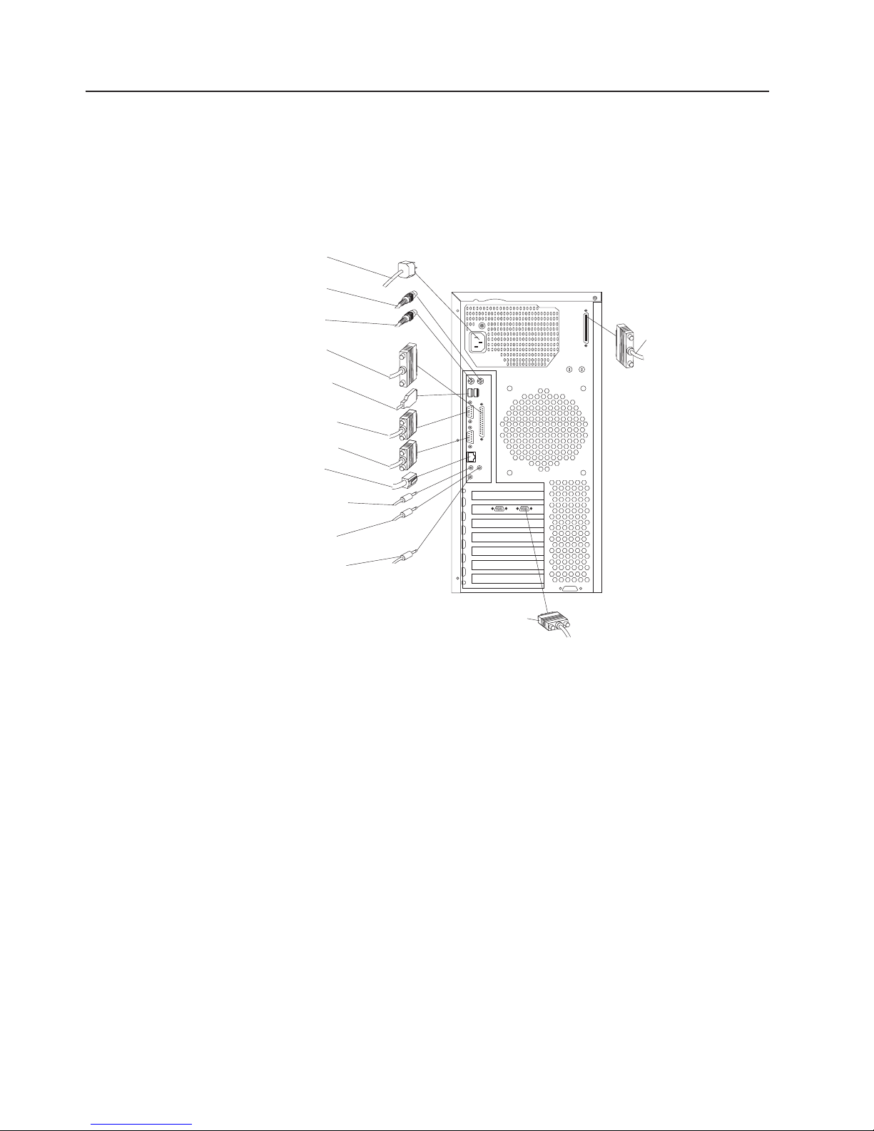
Input/output connector locations
The following illustration shows the input/output connectors and the expansion slots
on the rear of the computer.
Use the following illustration to help you connect cables to the rear of the computer.
Some connectors are color-coded. You might not have devices for all connectors
shown here.
Power
connector
Mouse
connector
Keyboard
connector
Parallel
connector
USB
connectors
Serial
connector 1
Serial
connector 2
Ethernet
connector
Audio line out/
headphone connector
Audio line in
connector
Microphone in
connector
SCSI connector
Monitor connector
Note: The location of the monitor connector is dependent on the video adapter
installed on the computer.
8 Hardware Maintenance Manual: IBM IntelliStation M Pro Type 6233 and 6850
Page 19

The following illustration shows the video connectors on models with a Fire GL
8800 or Wildcat III 6110 video adapter.
Digital
Analog
StereoGraphics
Digital
(DVI-I)
Note: The Wildcat III 6110 adapter occupies the AGP slot and the adjacent PCI
slot. Be careful when you install an adapter in PCI slot 2 because the space
between the Wildcat III 6110 adapter and PCI slot 2 is very limited, which
causes the adapters to be very close to each other.
If the software application supports it, the StereoGraphics connector on a Wildcat III
6110 video adapter is used for 3-D glasses or goggles.
Turning on the computer
After you plug one end of the computer power cord into the power supply connector
on the rear of the computer, and the other end of the power cord into an electrical
outlet, you can start the computer as follows:
v You can press the power control button on the front of the computer to start the
computer.
v If the computer is turned on and a power failure occurs, the computer will start
automatically when the power is restored.
the POST detects a problem when you turn on the computer, you will hear
If
repeating beeps. If this occurs, see “Diagnostics” on page 17 for more information.
During POST, the following messages are displayed:
v Press F1 for Configuration/Setup
v To Start the Product Recovery Program, Press F11
v <<< Press <CTRL><A> for SCSISelect Utility! >>>
The SCSI message only appears if a SCSI adapter is installed in the
Note:
computer.
If the computer is properly connected and configured to load a startup image from
the network, a request is sent and a startup image is loaded into the computer. If
the request is unsuccessful or there is no network connection, the operating system
and application programs are loaded from the hard disk drive.
The computer can ″wake up″ and be started remotely over a network, if it has a
properly configured network connection. For more information, see “Wake on LAN”
on page 13 and “Remote Administration” on page 14.
General information 9
Page 20

Shutting down the operating system
When you are ready to shut down the computer, follow these instructions to prevent
the loss of unsaved data or damage to the software programs. For more information
about shutting down the operating system, refer to the operating system
documentation that comes with the computer.
Complete the following steps to shut down the operating system.
1. Save any files you are working on.
2. Close all open applications.
3. Click the Windows Start button.
4. Click Shut Down.
5. Select Shut Down; then, click OK to confirm the request.
Turning off the computer
You can turn off the computer as follows:
Statement 5:
CAUTION:
The power control button on the device and the power switch on the power
supply do not turn off the electrical current supplied to the device. The device
also might have more than one power cord. To remove all electrical current
from the device, ensure that all power cords are disconnected from the power
source.
2
1
v You can press the power control button on the front of the computer. This starts
an orderly shutdown of the operating system, if this feature is supported by the
operating system, and places the computer in standby mode.
Note: After turning off the computer, wait at least five seconds before you press
the power control button to turn on the computer again.
v You can press and hold the power control button for more than four seconds to
cause an immediate shutdown of the computer and place the computer in
standby mode. Yo u can use this feature if the operating system stops functioning.
v If you cannot use the power control button to turn off the computer, disconnect
the computer power cords from the electrical outlets.
Note: After disconnecting the power cords, wait approximately 15 seconds for
the computer to stop running.
10 Hardware Maintenance Manual: IBM IntelliStation M Pro Type 6233 and 6850
Page 21

Operating certain features
This section provides an overview of some of the features of this computer.
Using video features
The computer has an accelerated graphics port (AGP) graphics adapter that uses a
standard video protocol for displaying text and graphic images on a monitor screen.
The adapter supports a variety of video modes. Video modes are different
combinations of resolution, refresh rate, and color defined by a video standard for
displaying text or graphics.
Video device drivers
To take full advantage of the graphics adapter in the computer, some operating
systems and application programs require custom software, known as video device
drivers. These preinstalled device drivers provide support for greater speed, higher
resolution, more available colors, and flicker-free images.
Device drivers for the graphics adapter and a README file with instructions for
installing the device drivers are provided on the Device Drivers and IBM Enhanced
Diagnostics CD that comes with the computer. If the computer has preinstalled
software, video device drivers are in the C:\IBMTOOLS\DRIVERS directory.
Note: Video device drivers for the Fire GL4 video adapter are in the
IBMTOOLS/DRIVERS/VIDEO/FIREGL4 directory.
You can use the device driver installation instructions if you ever need to reinstall
the device drivers, or if you need information on obtaining and installing updated
device drivers.
Changing monitor settings
To get the best possible image on the screen and to reduce flicker, you might need
to reset the resolution and refresh rate of the monitor. Yo u can view and change
monitor settings through the operating system using the instructions provided in the
README files on the Device Drivers and IBM Enhanced Diagnostics CD or in the
C:\ IBMTOOLS\DRIVERS directory on the hard disk drive.
Attention: Before you change any monitor settings, be sure to review the
information that comes with the monitor. Using a resolution or refresh rate that is
not supported by the monitor might cause the screen to become unreadable and
could damage the monitor. The information that comes with the monitor usually
includes the resolutions and refresh rates that the monitor supports. If you need
additional information, contact the manufacturer of the monitor.
To minimize screen flicker and jitter, set the monitor to the highest noninterlaced
refresh rate that the monitor supports. If the monitor complies with the VESA display
data channel (DDC) standard, it should already be set to the highest refresh rate
that the monitor and video controller can support. If you are not sure if the monitor
is DDC-compliant, see the documentation provided with the monitor.
If you have a dual-monitor video adapter and you connect both monitors but do not
see the second monitor, go to Start → Settings → Control Panel → Display
Properties → Settings → Display Type and enable the Multi-head option.
Note: Refer to the video adapter device driver README file and online help for
more information.
General information 11
Page 22

Using audio features
The computer has three audio connectors, and an integrated audio controller that
supports Sound Blaster applications and is compatible with the Microsoft Windows
Sound System. Using the audio controller, you can record sound and music. If you
connect external speakers to the Line out connector, you can play sound with
multimedia applications.
The audio connectors in the computer are 3.5 mm mini-jacks. A description of the
connectors follows.
Line out
This connector is used to send audio signals from the computer to external devices,
such as speakers with built-in amplifiers, headphones, multimedia keyboards, or the
audio Line in jack on a stereo system.
Line in
This connector is used to accept audio signals into the computer sound system
from external devices, such as line output from a stereo, television, or musical
instrument.
Mic
This connector is used to connect a microphone to the computer when you want to
record voices or other sounds on the hard disk drive. This connector and a
microphone can also be used by speech recognition software.
Note: If you experience interference or speaker feedback while recording, try
reducing the microphone recording volume (gain).
Updating system programs
System programs are the basic layer of software built into the computer. They
include the power-on self-test (POST), the basic input/output system (BIOS) code,
and the Configuration/Setup Utility program. POST is a set of tests and procedures
that are performed each time you turn on the computer. BIOS is a layer of software
that translates instructions from other layers of software into electrical signals that
the computer hardware can understand. You can use the Configuration/Setup Utility
program to view and change the configuration and setup of the computer.
System programs are stored in an electrically erasable programmable read-only
module (EEPROM) on the system board. This is sometimes referred to as flash
memory.
IBM occasionally makes changes and enhancements to the system programs.
When updates are released, they are available as downloadable files on the World
Wide Web at http://www.ibm.com.
You can update system programs by starting the computer using a flash update
diskette or by using the Remote Administration feature, if it is enabled. Instructions
for using system programs updates are included in a README file provided with
the downloadable files.
12 Hardware Maintenance Manual: IBM IntelliStation M Pro Type 6233 and 6850
Page 23

Managing the computer
The computer comes with features that a network administrator or file server can
use to remotely manage and control the computer.
IBM Director Agent
IBM Director Agent streamline and automate personal computer (PC) systems
management and support tasks, such as asset deployment and tracking. These
utilities are available for IBM computers at no additional charge, helping to reduce
the total cost of ownership of the networked computers.
IBM Director Agent enables you to view detailed information about the computer
hardware and software, set up alerts, monitor a variety of system resources, and
manage the asset security. For more information, go to
http://www.ibm.com/pc/support on the World Wide Web and search for IBM Director
Agent.
Wake on LAN
®
A network administrator can use Wake on LAN
to turn on the computer from a
remote location. When Wake on LAN is used with network management software,
many functions, such as data transfers, software updates, and POST or BIOS code
updates can be initiated on the computer remotely.
Note: If the computer power cord is plugged into a surge protector or power strip,
make sure that you turn off the computer by the power button, and not the
surge protector or power strip switch. Otherwise, the Wake on LAN feature
will not work.
Alert on LAN
The computer supports Alert on LAN technology, which provides notification of
changes in the computer system even when the computer is turned off. Working
with desktop management interface (DMI) and Wake on LAN technologies, Alert on
LAN helps manage and monitor the hardware and software features of the
computer.
Alert on LAN generates notifications when the computer cover is removed, an error
is detected during POST, or the computer is disconnected from the network or
unplugged from the electrical outlet. Alert on LAN works in conjunction with UM
Services.
Remote Program Load or Dynamic Host Configuration Protocol
A network administrator can use Remote Program Load (RPL) or Dynamic Host
Configuration Protocol (DHCP) to control the computer. RPL, when used with
software such as IBM LANClient Control Manager™, uses a feature called Hybrid
RPL to install hybrid images (or files) on the hard disk drive. If the computer is a
Hybrid RPL client, each time the computer starts from the network, LANClient
Control Manager downloads a small bootstrap program to the computer hard disk
drive and avoids the network traffic associated with a standard RPL.
DHCP enables network administrators centrally to manage and automate the
assignment of Internet Protocol (IP) addresses on a network.
General information 13
Page 24

Remote Administration
A network administrator can use the Remote Administration feature to remotely
update the POST and BIOS code in the computer.
Network-management software, such as LANClient Control Manager (LCCM), is
required to take advantage of this feature.
LANClient Control Manager
LANClient Control Manager is a graphical, computer-based system deployment
program that enables mass unattended installations of operating systems, software
images, device drivers, and BIOS code updates to remote systems. When used
with Wake on LAN, LCCM can remotely turn on the computer, so that the
installation can be done while the computer is not being used.
For more information or to download this software, visit
http://www.ibm.com/pc/us/desktop/lccm on the World Wide Web.
System Migration Assistant
System Migration Assistant (SMA) enables administrators to remotely transfer
configurations, profile settings, printer device drivers, and files from an IBM or
non-IBM computer to supported IBM systems.
For more information or to download this software, visit
http://www.pc.ibm.com/us/software/sysmgmt/products/sma on the World Wide Web.
Desktop Management Interface
DMI is a method for gathering information about the hardware and software in the
computer. In a network environment, network administrators can use DMI to
remotely monitor and control the computer.
Using security features
To deter unauthorized use of the computer, anti-intrusion and other security features
are provided with the computer.
Anti-intrusion features
IBM anti-intrusion features help protect against the theft of computer components,
such as the microprocessor, system memory modules, or hard disk drives.
A cover lock is built into the computer to prevent the cover from being removed.
Two identical keys for the cover lock are also supplied. A tag attached to the keys
has the key serial number and the address of the key manufacturer.
Note: Locksmiths are not authorized to duplicate the cover lock keys; you must
order replacement keys from the key manufacturer. When ordering
replacement keys, you will need the key code number.
You can also set a chassis-intrusion detector inside the computer to alert the
system administrator each time the computer cover is removed. For more
information about setting the chassis-intrusion alert, see “Configuration” on page 33.
If the computer uses the Alert on LAN feature and you are connected to a network
that uses Intel LANDesk
message is also sent to the network administrator console indicating that the
computer cover has been removed. For more information, see “Alert on LAN” on
page 13 and contact the network administrator.
14 Hardware Maintenance Manual: IBM IntelliStation M Pro Type 6233 and 6850
®
Desktop Manager or IBM LANClient Control Manager, a
Page 25

Component protection
The components in the computer have serial numbers on them. You can register
the components with a third-party security company to improve the chances of
identifying the components if they are ever stolen and recovered. For more
information about component registration, see the IBM support page at
http://www.ibm.com/pc/us/desktop/assetid/ on the World Wide Web.
Data protection
You can lose data from the hard disk drive for a variety of reasons. Security
violations, viruses, or hard disk drive failures can all contribute to data loss. To help
protect against the loss of valuable information, IBM has incorporated a data-saving
feature into the computer.
IBM security solutions: IBM security solutions help keep electronic business
transactions safe. They include the following:
v Data protection
v Locked keyboard
SMART
hard disk drive: The computer comes with a SMART hard disk drive that
is enabled to report potential hard disk failures. If an error is detected, a
DMI-compliant warning message is sent to the computer screen and, if the
computer is part of a network, to an administrator console. When an error is
detected, the data on the hard disk can be backed up and the drive replaced.
SMART Reaction: To help back up important data, IBM provides SMART
Reaction
™
software on the computers with preinstalled software and also on the
IBM Software Selections CD. SMART Reaction is a client/server software
application that helps users and administrators respond effectively to a warning
issued by the SMART hard disk drive.
Virus protection: The computer has built-in virus protection that can be enabled
through the Configuration/Setup Utility program. This built-in protection only checks
for viruses in the boot record. Also, Norton AntiVirus for IBM is available on the IBM
Software Selections CD.
Locking the keyboard: You can lock the keyboard so that others are unable to
use it. If a user password is set, the keyboard is locked when you turn on the
computer. You must type the correct password before the keyboard will unlock. You
can enable the user password feature with the BIOS Setup Utility program. See
Setting Security Passwords in Access IBM.
Some operating systems have a keyboard and mouse lock-up feature. Refer to the
documentation that comes with the operating system for more information.
General information 15
Page 26

16 Hardware Maintenance Manual: IBM IntelliStation M Pro Type 6233 and 6850
Page 27

Diagnostics
The following tools are available to help identify and resolve hardware-related
problems.
v Setup Utility program
v Power-On Self-Test (POST)
– POST Beep Codes
– Error Code Format
Diagnostics
v
v Recovery
– Full recovery
– Repair Utility
Setup Utility program
Attention:
A customized setup configuration (other than default settings) might exist on the computer
you are servicing. Running the Setup Utility program might alter those settings. Note the
current configuration settings and verify that the settings are in place when service is
complete.
The Setup Utility (configuration) program is stored in the permanent memory of the
computer. This program includes settings for the following:
v System Summary
v Product Data
v Devices and I/O Ports
v Processor Control
v Start Options
v Date and Time
v System Security
v Advanced Setup
v Power Management
v PC Health Status
run the Setup Utility program, use the following procedure.
To
1. Power-off the computer and wait for a few seconds until all in-use lights go off.
2. Power-on the computer.
3. When the Setup Utility prompt appears on the screen during start-up, press F1.
The Setup Utility menu will appear.
4. Follow the instructions on the screen.
Note: If prompted for a password, enter the supervisor password.
© Copyright IBM Corp. 2002 17
Page 28

POST
When you turn on the computer, it performs a series of tests to check the operation
of system components and some of the options that are installed in the computer.
This series of tests is called the power-on self-test, or POST.
If POST finishes without detecting any problems, the first window of the operating
system or application program appears.
Notes:
1. If you have a user password set, you must type the password and press Enter,
when prompted, before POST will continue.
2. A single problem might cause several error messages. When this occurs,
correct the cause of the first error message. After you correct the cause of the
first error message, the other error messages usually will not occur the next
time you run the test.
The possible types of beep codes that the system might emit are:
Repeating long beeps
Indicates that a memory error has occurred. Ensure that all RIMMs are
correctly installed.
One long beep and two short beeps
Indicates that a video error has occurred and the BIOS code cannot
initialize the video screen to display any additional information. Ensure that
the video adapter is correctly installed.
Diagnostics
The Diagnostics program uses a full range of diagnostic utilities to determine the
operating condition of the computer’s hardware components.
For a complete list of error codes and messages, see “Symptom-to-FRU index” on
page 83.
Diagnostics program download
To download the Diagnostics program, do the following:
v Go to http://www.ibm.com/ .
v Select Support.
v Select Desktop computing from the ″Search by Category″ pull-down menu.
v Select IntelliStation or Type from the ″Product Family″ list.
v Search for the machine type in the ″Quick Path″ box on the left.
v Select Diagnostics from the ″Downloadable files by Category″ pull-down menu
or go directly to the link PC Enhanced Diagnostics diskette from the
″Downloadable files by date″ list. This link will take you to the self-starting utility
download and instructions.
Navigating through the diagnostics programs
Use the cursor movement keys to navigate within the menus.
v The Enter key is used to select a menu item.
v The Esc key is used to back up to the previous menu.
v For online help select F1.
18 Hardware Maintenance Manual: IBM IntelliStation M Pro Type 6233 and 6850
Page 29

Running diagnostics tests
There are four ways to run the diagnostic tests.
1. Using the cursor movement keys, highlight Run Normal Test or Run Quick
Test from the Diagnostics menu and then press Enter.
This will automatically run a pre-defined group of tests from each test category.
Run Normal Test runs a more extensive set of tests than does Run Quick Test
and takes longer to execute.
2. Press F5 to automatically run all selected tests in all categories. See ″Test
Selection″.
3. From within a test category, press Ctrl-Enter to automatically run only the
selected tests in that category. See ″Test Selection″.
4. Using the cursor movement keys, highlight a single test within a test category,
then press Enter. This will run only that test.
Esc at any time to stop the testing process.
Press
Test results, (N/A, PASSED, FAILED, ABORTED), are displayed in the field beside
the test description and in the test log. See “Viewing the test log” on page 23.
Test selection
To select one or more tests, use the following procedure.
1. Open the corresponding test category.
2. Using the cursor movement keys, highlight the desired test.
3. Press the space bar.
A selected test is marked by >>. Pressing the space bar again de-selects a test
and removes the chevron.
4. Repeat steps 2 and 3 above to select all desired tests.
Using the IBM Product Recovery CD
The IBM Product Recovery CD is provided with the computer so that you can
reinstall the operating system, preinstalled applications, and device drivers in case
of a hard disk failure or other damage to files.
Note: The Product Recovery CD is only available as a FRU.
To use the IBM Product Recovery CD, place IBM Product Recovery CD in the
CD-ROM drive, then shut down the operating system and turn off the computer.
Turn on the computer and the Product Recovery program will begin. If the CD does
not start, you may need to change the primary startup sequence.
Recovering the operating system and support software
Attention: The recovery process deletes all information stored on the primary
partition (drive C), including any personal files, data, and software stored on the
hard disk drive. If possible, back up the data before starting this process.
The IBM Product Recovery CD for Windows 2000 Professional contains a Windows
98 startable CD image that copies files from the CD to the hard disk. The CD
initially runs Windows 98 DOS, and then installs Windows 2000 Professional.
Diagnostics 19
Page 30

To run the FDISK command from IBM Product Recovery CD, place IBM Product
Recovery CD in the CD-ROM drive, press Esc at the Recover Main Menu; then
type FDISK at the command prompt. Delete the primary partition, leave the IBM
Product Recovery CD in the CD-ROM drive, and restart the computer. The IBM
Product Recovery CD partitions the hard disk correctly.
Use the following steps to recover or reinstall the IBM preinstalled operating system
and software:
1. Make backup copies of configuration files and any files you created. Any files
not backed up will be lost.
2. Insert the IBM Product Recovery CD into the CD-ROM drive.
3. Restart the computer. If the computer does not start from the CD, you need to
change the startup sequence. (See “Changing the startup sequence to start
from the CD” on page 25.)
4. You might be prompted to select the appropriate operating system.
5. The Product Recovery program main menu appears with the following options:
Full recovery
Select this option to reformat the hard disk and restore the computer to
the original preinstalled software.
Repair Utility
Select this option to run the emergency repair utility program.
Select the option you need and follow the instructions on the screen.
6. When the recovery is complete, remove the IBM Product Recovery CD and
restart the computer.
7. If you changed the startup sequence, make sure you change it back
immediately.
Additional resources
The IBM Product Recovery CD for Windows 2000 Professional contain additional
subdirectories on the root directory called \support\tools directory\, and
\valueadd. These directories include application updates provided by Microsoft for
your convenience. Later updates of these files might be available on the Microsoft
Web site.
Installing other operating systems
If you install (or reinstall) another operating system, you might need additional
software or device drivers. Hardware-specific support software is available on the
Device Driver and IBM Enhanced Diagnostics CD. If you experience problems with
device drivers installed from this CD, you can obtain updated device drivers at
http://www.ibm.com/support on the World Wide Web.
Before installing any operating system, be sure you obtain the latest updates.
Contact the operating system manufacturer or, if applicable, check the
manufacturer’s World Wide Web site to obtain the updates.
To install an operating system, follow the instructions in the documentation provided
with the operating system and any updates.
Additional information about operating systems might be available at
http://www.ibm.com/support on the World Wide Web.
20 Hardware Maintenance Manual: IBM IntelliStation M Pro Type 6233 and 6850
Page 31

Module test menu/hardware configuration report
Depending on the diagnostics version level you are using, the installed devices in
the computer are verified in one of two ways.
1. At the start of the diagnostic tests, the Module Test Menu is displayed. Normally,
all installed devices in the computer are highlighted on the menu.
2. At the start of the diagnostic tests, the main menu appears. From this menu,
select System Info, then select Hardware Configuration from the next menu.
Normally, all installed devices in the computer are highlighted on this report.
If an installed device is not recognized by the diagnostics program, then review the
following:
v The diagnostic code for the device is not in the Diagnostics program. Run the
diagnostics provided with that device.
v The missing device is defective or it requires an additional diskette or service
manual.
v An unrecognizable device is installed.
v A defective device is causing another device not to be recognized.
v The SCSI controller failed (on the system board or SCSI adapter).
v Use the procedure in “Undetermined problems” on page 96 to find the problem.
If a device is missing from the list, replace it. If this does not correct the problem,
use the procedure in “Undetermined problems” on page 96.
Memory Diagnostic tests
Follow the steps below to locate the Memory Diagnostic tests options.
1. Select the DIAGNOSTICS option on the toolbar and press Enter.
Note: When you see the intel station logo press tab to get to the memory test
screen.
2. Highlight either the Memory Test-Full or Memory Test-Quick option and press
Enter.
v Memory Test-Full
The full memory test will take about 80 seconds per MB of memory and will
detect marginal, intermittent, and solid (stuck) memory failures.
v Memory Test-Quick
The quick memory test will take about 20 seconds per MB of memory and
will detect solid (stuck) memory failures only.
Either level of memory testing can be performed on all memory or a single
Note:
SIMM, DIMM or RIMM socket.
Only sockets containing a SIMM, DIMM or RIMM can be selected for testing.
Unpopulated sockets are noted by ″........″ beside the test description.
Alert-On LAN test
The Alert On LAN test does the following:
v Determines if Alert On LAN is supported on the system.
v Checks the revision ID register.
v Verifies the EEPROM checksum.
v Validates that a software alert can be sent.
Diagnostics 21
Page 32

Test results
Diagnostics test results will produce the following error code format:
Function Code Failure Type DeviceID Date ChkDigits Text
v Function Code:
Represents the feature or function within the PC.
v Failure Type:
Represents the type of error encountered.
v Device ID:
Contains the component’s unit-ID which corresponds to either a fixed disk drive,
removable media drive, serial or parallel port, processor, specific SIMM or DIMM,
or a device on the PCI bus.
v Date:
Contains the date on which the diagnostic test was run. The date is retrieved
from CMOS and displayed using the YYYYMMDD format.
v ChkDigits:
Contains a 2-digit check-digit value to ensure the following:
– Diagnostics were run on the specified date.
– Diagnostics were run on the specified IBM computer.
– The diagnostic error code is recorded correctly.
Text:
v
Description of the error.
Note:
Hard file Smart test
Use the Hard File Smart Test when the system management tool has detected a
hard file SMART alert.
The Smart test does the following:
v Interrogates IDE devices for support of the SMART instruction set.
v Issues an ENABLE SMART command to make sure SMART functionality is
active.
v Checks the SMART RETURN STATUS command to determine if any thresholds
have been exceeded.
thresholds have been exceeded, an error message is shown, and the test fails. If
If
no SMART is supported by the drive, the test returns with ″N/A″.
See “Diagnostic error codes” on page 86 for error code listings.
22 Hardware Maintenance Manual: IBM IntelliStation M Pro Type 6233 and 6850
Page 33

Quick and Full erase - hard drive
The Diagnostics program offers two hard drive format utilities:
v Quick Erase Hard Drive
v Full Erase Hard Drive
Quick Erase Hard Drive provides a DOS utility that performs the following
The
steps.
v Destroys the Master Boot Record (MBR) on the hard drive.
v Destroys all copies of the FAT Table on all partitions (both the master and
backup).
v Destroys the partition table.
v Provides messages that warn the user that this is a non-recoverable process.
Full Erase Hard Drive provides a DOS utility that performs the following steps.
The
v Performs all the steps in Quick Erase.
v Provides a DOS utility that writes random data to all sectors of the hard drive.
v Provide an estimate of time to completion along with a visual representation of
completion status.
v Provides messages that warn the user about non-recoverable process.
Important: Make sure that all data is backed up before using the Quick or Full Erase
functions.
To select the Quick Erase or Full Erase Hard Drive utility, use the following
procedure.
1. Select the UTILITY option on the toolbar and press Enter.
2. Select either the QUICK ERASE or FULL ERASE HARD DISK option and follow
the instructions.
Iomega Zip drive test
Use the Iomega Zip Drive Test to test the Zip drive and the drive interface. The test
takes about 20 seconds to run.
The default tests the following:
v Controller
v Max Seek (50 times)
v Random Seek (300 sectors)
Viewing the test log
Errors reported by the diagnostic test will be displayed by the program as a failed
test.
To view details of a failure or to view a list of test results, use the following
procedure from any test category screen.
v Press F3 to activate the log file.
v Press F3 again to save the file to diskette or F2 to print the file.
Diagnostics 23
Page 34

When to use the Low-Level Format program
Notes:
1. The low-level format is not available on all diagnostic diskettes.
2. Before formatting the hard disk drive, make a backup copy of the files on the drive to be
formatted.
Use the Low-Level Format program in the following situations:
v When you are installing software that requires a low-level format.
v When you get recurring messages from the test programs directing you to run
the Low-Level Format program on the hard disk.
v As a last resort before replacing a hard disk drive.
Preparing the hard disk drive for use
When the Low-Level Format program is finished, restore to the hard disk all the
files that you previously backed up.
1. Partition the remainder of the hard disk for the operating system. (The
commands vary with the operating system. Refer to the operating system
manual for instructions.)
2. Format the hard disk using the operating system. (The commands vary with the
operating system. Refer to the operating system manual for instructions.)
3. Install the operating system.
are now ready to restore the files.
You
This chapter describes diagnostic tools that are available to you. You can use these
tools to identify and correct problems that might come up as you use the computer.
If the computer does not start when you press the power switch, do the following:
v Make sure the computer and monitor are connected to working electrical outlets.
v Make sure all cables are securely connected to the correct locations.
this does not correct the problem, have the computer serviced.
If
Computer problems can be caused by hardware, software, or user error (for
example, pressing the wrong key).
Check the hardware by following the procedures in this chapter. Yo u can also use
the diagnostic programs provided with the computer (see “IBM Enhanced
Diagnostics” on page 26 for a description of these programs).
If the hardware checks out and you have not made a user error, you might have a
software problem. If you suspect that you have a software problem, see
“Software-generated error messages” on page 25 and the operating system
documentation that comes with the computer. If you have installed software
applications yourself, see the documentation that comes with the software.
The following tools are available to diagnose hardware-related problems:
v Power-on self-test (POST)
v Troubleshooting charts
v IBM Enhanced Diagnostics program
24 Hardware Maintenance Manual: IBM IntelliStation M Pro Type 6233 and 6850
Page 35

Small computer system interface (SCSI) error messages
These messages appear if a problem or conflict is detected by the SCSI
subsystem. See the SCSI documentation on the Software Selections CD that
comes with the computer for information about these messages.
Software-generated error messages
These messages appear if a problem or conflict is detected by the application
program, the operating system, or both. Error messages for operating system and
other software problems are generally text messages, but might be numeric codes.
For information about these software error messages, see the information supplied
with the operating system or application program.
Diagnostic error codes and messages
These codes and messages appear if a hardware problem is detected by one of the
IBM Enhanced Diagnostics programs. Along with error codes, the messages
present text information that can be used to identify a failing part. For more
information, see “IBM Enhanced Diagnostics” on page 26.
Changing the startup sequence to start from the CD
If the computer does not start from the CD on the first try, you need to change the
startup sequence in the Configuration/Setup Utility program. Follow these steps to
change the startup sequence:
1. Turn on the computer. If the computer is already on when you start this
procedure, you must shut down the operating system, turn off the computer,
wait a few seconds until all in-use lights go off, and restart the computer. (Do
not use Ctrl+Alt+Del to restart the computer.)
2. When the Configuration/Setup Utility prompt appears in the lower-left corner of
the screen during startup, press F1. (This prompt appears on the screen for
only a few seconds. You must press F1 quickly.
Note: If prompted for a password enter supervisor password.
3. Select Start Options from the Configuration/Setup Utility program menu.
4. Select Startup Sequence from the Start Options from the menu.
5. Note the first startup device shown in the Startup Sequence. Yo u will need this
information to restore the original startup sequence after you complete the
recovery process.
6. Change the First Startup Device in the Startup Sequence to the CD-ROM
drive.
7. Press the Esc key until you return to the Configuration/Setup Utility program
menu.
8. Before you exit from the program, select Save and Exit Settings from the
Configuration/Setup Utility program menu and press the Enter key.
9. Turn off the computer.
Remember to restore the original startup sequence when you have finished
Note:
using the CD.
Diagnostics 25
Page 36

IBM Enhanced Diagnostics
IBM provides programs that you can run to diagnose problems you suspect to be
hardware related. Several utility programs that provide helpful information about the
computer are also included. The user interface for running these diagnostic and
utility programs is provided by PC-Doctor for Windows.
The IBM Enhanced Diagnostics program will isolate the computer hardware from
software that was preinstalled (or that you have installed) on the hard disk drive.
The programs run independently of the operating system, and must be run either
from CD or diskette. This method of testing is generally used when other methods
are not accessible or have not been successful in isolating a problem suspected to
be hardware related.
The Device Driver and IBM Enhanced Diagnostics CD comes with the computer. To
run the IBM Enhanced Diagnostics program from the Device Driver and IBM
Enhanced Diagnostics CD, do the following:
1. Change the start up sequence for the computer. See “Changing the startup
sequence to start from the CD” on page 25.
2. Insert the Device Driver and IBM Enhanced Diagnostics CD into the CD-ROM
drive.
3. Shut down the computer.
4. Start up the computer. The IBM Enhanced Diagnostics program will
automatically run.
5. Follow the instructions on the screen.
can also download the latest image of the diagnostics from the IBM Web site.
You
To download the latest image of the IBM Enhanced Diagnostics from the Web site
and create a startable Enhanced Diagnostics diskette:
1. Go to http://www.ibm.com/pc/us/intellistation on the World Wide Web.
2. Click Support. From the Family drop-down list, select a family. Click
Downloadable files on the left side of the screen; then, select Diagnostics
from the Downloadable files by Category drop-down list.
3. Download the.exe file to a hard disk directory (not to a diskette).
4. Go to a DOS prompt and change to the directory where you downloaded the
file.
5. Insert a blank high-capacity diskette in diskette drive A.
6. Type the following and press Enter:
filename a:
Where filename is the name of the file you downloaded from the Web.
self-extracting downloaded file is copied to the diskette, and a startable IBM
The
Enhanced Diagnostics diskette is created.
To start the IBM Enhanced Diagnostics program using the diagnostic diskette, do
the following:
1. Turn off the computer and all attached devices.
2. Insert the IBM Enhanced Diagnostics diskette into diskette drive A.
3. Turn on all attached devices; then turn on the computer.
4. Follow the instructions on the screen.
26 Hardware Maintenance Manual: IBM IntelliStation M Pro Type 6233 and 6850
Page 37

Other diagnostic programs
The computer also contains diagnostic programs designed specifically for the
Windows operating environment. Because these diagnostics work with the operating
system, they not only test the hardware, but they also analyze certain software
components of the computer. They are especially useful in isolating problems
related to the operating system and device drivers.
PC-Doctor for Windows
To use PC-Doctor for Windows:
1. If you have not already done so, install the program onto the hard disk drive.
2. To run the program after it is installed, select it from the Programs choice on
the Windows Start menu and follow the instructions on the screen. Help is
available online.
Using the ConfigSafe program
ConfigSafe can be used as a troubleshooting tool, especially if problems develop
after you install a new application or option. Before you make any changes to the
system configuration, use ConfigSafe to take a snapshot of the current, working
operating system configuration. If you have preinstalled software, ConfigSafe
automatically takes a snapshot of the initial operating system configuration settings
when you first start up the computer. Then you can easily return to that
configuration if the computer becomes disabled by changes in the configuration
files.
ConfigSafe Save Our System (SOS) feature
ConfigSafe has an SOS feature that can be used in a DOS environment if the
Windows desktop becomes unusable. To use the SOS feature of ConfigSafe:
1. Access a DOS prompt.
2. At the command prompt, type cd\cfgsafe. Press Enter.
3. Type sos. Press Enter
4. Select the most recent configuration that is dated before the start of the
problem. Press Enter.
5. Restart the computer.
the problem is not solved, you can repeat these steps selecting a different saved
If
configuration, or using the Undo button. (The Undo button is only available in the
Windows version of ConfigSafe.)
Support documentation is built into the online Help system. To access online Help,
run the ConfigSafe program. The online Help files will appear in the pull-down menu
on the right side of the screen.
Diagnostics 27
Page 38

Erasing a lost or forgotten password (clearing CMOS)
This section describes how to erase lost or forgotten passwords. For more
information about lost or forgotten passwords, refer to Access IBM on the desktop.
To erase a forgotten password, follow these steps:
1. Turn off the computer and all attached devices.
2. Unplug the power cord.
3. Remove the cover. See “Removing the cover and front bezel” on page 47.
4. See the illustration below for the CMOS jumper location.
5. Move the jumper from the standard position on pins 1 and 2 to the
CMOS jumper
maintenance, or configure position (pins 2 and 3).
6. Replace the cover and connect the power cords. See “Removing the cover
and front bezel” on page 47 and “Replacing the cover and connecting the
cables” on page 65.
7. After you restart the computer, the BIOS Setup Utility screen displays.
8. In the Maintenance screen, you can clear CMOS settings.
9. Press Esc.
10. Select Exit from the menu.
11. Select Exit Saving Changes.
12. Follow the instructions on the screen.
You must remove the cover again to place the jumper to the normal setting.
Note:
28 Hardware Maintenance Manual: IBM IntelliStation M Pro Type 6233 and 6850
Page 39

Recovering from a POST/BIOS update failure
If power to the computer is interrupted while POST/BIOS is being updated (flash
update), the computer might not restart (reboot) correctly or might not display video
(no video). If this happens, use the following procedure to recover:
1. Power-off the computer and remove the cover and front bezel.
2. Remove the system board Configure jumper (J5B2). Refer to “System board
connectors” on page 42″ or the label inside the computer for more information.
3. Insert the upgrade diskette into the diskette drive.
4. Power-on the computer. The IBM Logo will appear.
Note: Depending on the amount of memory installed, it may take up to a
minute for the Logo to appear.
5. When the Flash Update Utility appears, select the country/keyboard, then press
Enter.
6. If the computer serial number was previously recorded, the number is displayed
with an option to update it. Press Y to update the serial number.
7. Type the 7-digit serial number of the computer you are servicing, then press
Enter.
8. Follow the instructions on the screen to complete the flash (BIOS/VPD) update
procedure.
9. When you are instructed to reboot the computer, power-off the computer and
replace the Configure jumper (J5B2). Then replace the cover and power-on the
computer.
Replacing the battery
The computer has a special type of memory that maintains the date, time, and
settings for built-in features, such as serial- and parallel-port assignments
(configuration). A battery keeps this information active when you turn off the
computer.
The battery requires no charging or maintenance throughout its life; however, no
battery lasts forever. If the battery fails, the date, time, and configuration information
are lost, and an error message is displayed when you turn on the computer.
Note: If Enhanced Security is enabled, the administrator password is not lost when
the battery fails.
If you replace the original lithium battery with a heavy-metal battery or a battery with
heavy-metal components, be aware of the following environmental consideration.
Batteries and accumulators that contain heavy metals must not be disposed of with
normal domestic waste. They will be taken back free of charge by the manufacturer,
distributor, or representative, to be recycled or disposed of in a proper manner.
Diagnostics 29
Page 40

Statement 2:
CAUTION:
When replacing the lithium battery, use only IBM Part Number 33F8354 or an
equivalent type battery recommended by the manufacturer. If your system has
a module containing a lithium battery, replace it only with the same module
type made by the same manufacturer. The battery contains lithium and can
explode if not properly used, handled, or disposed of.
Do not:
v Throw or immerse into water.
v Heat to more than 100°C (212°F)
v Repair or disassemble
Dispose
of the battery as required by local ordinances or regulations.
For further information on battery disposal, call IBM at 1-800-IBM-4333
(1-800-426-4333) in the U.S. For information outside of the U.S., contact an IBM
reseller or marketing representative.
To change the battery, do the following:
1. Turn off the computer and all attached devices.
2. Unplug the power cord.
3. Remove the cover. See “Removing the cover and front bezel” on page 47.
4. Disconnect the hard disk drive power cable and the hard disk drive fan cable
on the memory board.
5. Push the tab on the back of the memory board inward and pull the memory
board out of the chassis.
Note: If any long adapters are installed in PCI slots, they must also be
removed. These adapters must also be replaced before replacing the
memory board.
6. Locate the battery. Refer to the system board label inside the computer.
7. Remove the old battery.
8. Install the new battery.
30 Hardware Maintenance Manual: IBM IntelliStation M Pro Type 6233 and 6850
Page 41

9. Replace the memory board and any adapters that were removed to gain
access to the battery.
10. Install the cover. See “Completing the installation” on page 71.
11. Plug in the power cord.
Note: When the computer is turned on for the first time after battery
replacement, an error message might be displayed. This is normal after
the battery is replaced.
12. Turn on the computer and all attached devices.
13. See “Using the Configuration/Setup Utility program” on page 33 to set the date
and time and any passwords.
14. Dispose of the old battery as required by local ordinances or regulations.
Diagnostics 31
Page 42

32 Hardware Maintenance Manual: IBM IntelliStation M Pro Type 6233 and 6850
Page 43

Configuration
The following configuration programs are provided with the computer:
Configuration/Setup Utility program
The Configuration/Setup Utility program is part of the BIOS code that
comes with the computer. Yo u can use this program to configure serial and
parallel-connector assignments, change the drive startup sequence, set the
date and time, set passwords, and set the chassis-intrusion alert. See
“Using the Configuration/Setup Utility program” for more information.
SCSISelect Utility program
The SCSISelect Utility is a built-in program that enables you to configure
the devices that are attached to the SCSI adapter (on some models). Use
this program to change default values, resolve configuration conflicts, and
perform a low-level format on a SCSI hard disk drive. See “Using the
SCSISelect Utility program (some models)” on page 36 for more
information.
PXE Boot Agent Utility
The Preboot eXecution Environment (PXE) Boot Agent Utility program is
part of the BIOS code that comes with the computer. Yo u can use this
program to select operating-system wake-up support and to set menu wait
times. For information on how to start this utility, see “Using the PXE Boot
Agent Utility program” on page 38.
Using the Configuration/Setup Utility program
This section provides instructions for starting the Configuration/Setup Utility program
and descriptions of the menu choices that are available.
Starting the Configuration/Setup Utility program
Complete the following steps to start the Configuration/Setup Utility program.
1. Turn on the computer and watch the monitor screen.
2. When the message Press F1 for Configuration/Setup displays, press F1.
3. Follow the instructions that appear on the screen.
© Copyright IBM Corp. 2002 33
Page 44

The Configuration/Setup Utility main menu choices
From the Configuration/Setup Utility main menu, you can select settings that you
want to change. The Configuration/Setup Utility main menu is similar to the
following.
CMOS Setup Utility - Copyright (c) 1984 - 2001 Award Software
Configuration/Setup Utility
Select Option:
System Summary
Product Data
Devices & I/O Ports
Start Options
Date and Time
System Security
Advanced Setup
Power Management Setup
Save & Exit Setup
Load Optimized Defaults
Exit Without Saving
Move Enter: Select F1: General Help
F10: Save ESC: Exit
Notes:
1. Press F1 to display help information for a selected menu item.
2. Choices on some menus might differ slightly from the ones that are described in
this book, depending on the version of BIOS code in the computer.
3. If both a power-on and administrator password are set, you can type either
password at the password prompt that appears as you start the computer.
However, if you want to change the settings in the Configuration/Setup, you
must type the administrator password to access the full configuration menus. If
you type the power-on password, you will see limited information in the
Configuration/Setup program. For more information about setting passwords,
see “Using passwords” on page 36.
The Configuration/Setup Utility main menu choices are as follows:
v System Summary
Select this choice to display configuration information. This includes the type and
speed of the microprocessor and the amount of memory that is installed.
Changes that you make to configuration settings appear on this summary screen.
You cannot edit the fields.
This choice appears on both the full and limited Configuration/Setup Utility
menus.
v Product Data
Select this choice to view system information, such as the machine type and
model, the computer serial number, and the revision level or issue date of the
BIOS code that is stored in the flash EEPROM.
v Devices and I/O Ports
Select this choice to view or change the assignments for devices and
input/output ports. This choice appears only on the full Configuration/Setup Utility
main menu.
34 Hardware Maintenance Manual: IBM IntelliStation M Pro Type 6233 and 6850
Page 45

v Start Options
Select this choice to view or change the start options. Start options take effect
when you start the computer.
You can designate keyboard operating characteristics, such as the keyboard
speed, or specify whether the computer starts with the keyboard number lock on
or off.
The computer uses a startup sequence to determine the device from which the
operating system starts. For example, you can define a startup sequence that
checks for a startable diskette in the diskette drive; then, checks the hard disk
drive, and then checks a network adapter.
You can enable a virus-warning test that checks for changes in the master boot
record at startup. You also can choose to run POST in the quick mode, or read
the microprocessor serial number.
v Processor Control
Select this choice to display processor speed information. If the processor speed
is accidently changed, use this choice to reset the processor speed based on the
computer model.
v Date and Time
Select this choice to set the system date and time.
The system time is in a 24-hour format: hour:minute:second.
v System Security
Select this choice to set a power-on or an administrator password. See “Using
passwords” on page 36 for more information. Yo u also can enable the
chassis-intrusion detector to alert you each time the computer cover is removed.
v Advanced Setup
Select this choice to change values for advanced hardware features, such as
Cache Control and PCI configuration.
A message displays above the choices on this menu to alert you that the system
might malfunction if these options are configured incorrectly. Follow the
instructions on the screen carefully.
– Cache Control
Select this choice to enable or disable the microprocessor cache.
Attention: Do not make changes to the Cache Control unless directed to do
so by an IBM authorized service representative.
– ROM Shadowing
Select this choice to enable or disable the state of ROM shadowing.
– Chipset Feature
Select this choice to modify settings that control features of the core chip set
on the system board.
Attention: Do not make changes to the Chipset Feature unless directed to
do so by an IBM authorized service representative.
– Memory Settings
Select this choice to manually enable or disable a bank of memory.
If a memory error is detected during POST or memory configuration, the
computer can automatically disable the failing memory bank and continue
operating with reduced memory capacity. If this occurs, you must manually
enable the memory bank after the problem is corrected. Select Memory
Settings from the Advanced Setup menu, and use the arrow keys to highlight
the bank that you want to enable; then, use the arrow keys to select Enable.
Configuration 35
Page 46

v Power Management Setup
v PC Health Status
v Save and Exit Setup
v Load Optimized Defaults
v Exit Without Saving
Using passwords
You can use any combination of up to seven characters (A–Z, a–z, and 0–9) for the
power-on password or the administrator password. When you have set one or both
of the passwords, record the passwords and keep them in a secure place.
If both a power-on and administrator password are set, you can type either
password at the password prompt that appears as you start the computer. However,
if you want to change the settings in the Configuration/Setup, you must type the
administrator password to access the full configuration menus. If you type the
power-on password, you can only view limited information in the
Configuration/Setup program.
Select this choice to enable or disable system power settings. This includes
automatic power-on settings such as Wake on LAN and Wake on Alarm.
Select this choice to display the computer temperature and voltage status.
Select this choice to save the customized settings.
Select this choice to discard the changes and restore the factory settings.
Select this choice if you want to exit without saving changes, or if no changes
have been made.
If you forget the power-on password, you can regain access to the computer
through one of the following methods:
v Start the Configuration/Setup Utility program and change the power-on password.
v Change the jumper position on the complimentary metal oxide semiconductor
(CMOS) jumper as described in “Erasing a lost or forgotten password (clearing
CMOS)” on page 28.
Using the SCSISelect Utility program (some models)
SCSISelect is a built-in, menu-driven configuration utility program that you can use
to:
v View the default SCSI IDs
v Locate and correct configuration conflicts
The following sections provide instructions for starting the SCSISelect Utility
program and descriptions of the menu choices that are available.
Starting the SCSISelect Utility program
Complete the following steps to start the SCSISelect Utility program:
1. Turn on the computer.
2. When the <<< Press <CTRL><A> for SCSISelect¬ Utility! >>> prompt
displays, press Ctrl+A.
3. When the Would you like to configure the host adapter or run the SCSI
disk utility? question displays, make your selection; then, press Enter.
36 Hardware Maintenance Manual: IBM IntelliStation M Pro Type 6233 and 6850
Page 47

4. Use the arrow keys to select a choice from the menu.
v Press Esc to exit the SCSISelect Utility program.
v Press the F5 key to switch between color and monochrome modes (if the
monitor permits).
5. Follow the instructions on the screen to change the settings of the selected
items; then, press Enter.
SCSISelect menu choices
The following choices appear on the SCSISelect Utility menu:
Configure/View Host Adapter Settings
Select this choice to view or change the SCSI controller settings. To reset
the SCSI controller to its default values, press F6; then, follow the
on-screen instructions.
You can view or change the following controller settings:
v Host Adapter SCSI ID
Select this choice to view the SCSI controller identification (ID), which is
usually 7.
v SCSI Parity Checking
Select this choice to view the assigned value of Enabled.
v Host Adapter SCSI Termination
Select this choice to view the assigned value of Automatic.
v Boot Device Options
Select this choice to configure startable-device parameters. Before you
can make updates, you must know the ID of the device whose
parameters you want to configure.
v SCSI Device Configuration
Select this choice to configure SCSI-device parameters. Before you can
make updates, you must know the ID of the device whose parameters
you want to configure.
Advanced
Select this choice to view or change the settings for advanced configuration
options. These options include enabling support for large hard disk drives
and support for drives with Ultra SCSI speeds.
Note: The Maximum Sync Transfer Rate represents the transfer rate for
Ultra SCSI devices.
– The transfer rate for Ultra160 low voltage differential (LVD)
devices is 160.0 MBps.
– The transfer rate for Ultra2 SCSI LVD devices is 80.0 MBps.
– The transfer rate for Fast SCSI devices is 20.0 MBps.
Configuration Options
Configuration 37
Page 48

SCSI Disk Utilities
Select this choice to view the SCSI IDs that are assigned to each device or
to format a SCSI device.
To use the utility program, select a drive from the list. Read the on-screen
instructions carefully before making a selection.
Note: If you press Ctrl+A before the selected drives are ready, an
Unexpected SCSI Command Failure screen might appear. Restart
the computer and watch the SCSISelect messages as each drive
starts. When the drive that you want to view or format starts, press
Ctrl+A.
Using the PXE Boot Agent Utility program
The PXE boot agent is a built-in, menu-driven configuration utility program that you
can use to:
v Select whether or not to display setup prompt
v Set menu wait time
v Select OS wake up support
Attention: The network startup protocols and startup order options are not
supported on this product.
The following sections provide instructions for starting the PXE Boot Agent Utility
program and descriptions of the menu choices that are available.
Starting the PXE boot agent utility program
To start the PXE Boot Agent Utility program:
1. Turn on the computer.
2. When the Initializing Intel (R) Boot Agent Version X.X.XX PXE 2.0 Build
XXX (WfM 2.0) prompt appears, press Ctrl+S.
Note: By default you will have two seconds after the prompt appears on the
screen to press Ctrl+S.
3. Use the arrow keys or press Enter to select a choice from the menu.
v Press Esc to return to the previous menu.
v Press the F4 key to exit.
Follow the instructions on the screen to change the settings of the selected
4.
items; then, press Enter.
PXE boot agent utility menu choices
The following choices appear on the PXE boot agent utility menu:
v Network Boot Protocol
PXE is the default value for this menu item.
Note: Do not change this value. There are no other network boot protocols
supported.
v Boot Order
Attention: This option is not supported on this product. To change the boot
order use the Configuration/Setup utility. See “Using the Configuration/Setup
Utility program” on page 33 for more information.
38 Hardware Maintenance Manual: IBM IntelliStation M Pro Type 6233 and 6850
Page 49

v Show setup prompt
Select this choice to either display the PXE setup prompt or disable it. Disable is
the default setting.
When this choice is enabled, the prompt Press Ctrl+S to enter the setup menu
appears on the screen under the initializing prompt.
v Setup time wait menu
Select this choice to set the amount of time (in seconds) that the system will
pause during initialization for a Ctrl+S input.
– 2 seconds (Default)
– 3 seconds
– 5 seconds
– 8 seconds
Legacy OS wake up support
v
Select this choice to enable or disable the operating system wake-up support.
– Disabled (Default)
– Enabled
BIOS levels
Notes:
1. Use the default setting for Advanced Configuration and Power Interface (ACPI)
aware operating systems, such as Windows 2000 and Windows NT.
2. If the computer is running a non-ACPI operating system, you must set this
selection to Enable to use the Wake-on-LAN support.
3. When using a non-ACPI operating system, do not send a wake up packet to the
computer while it is turned on.
An incorrect level of BIOS can cause false error and unnecessary FRU
replacement. Use the following information to determine the current level of BIOS
installed in the computer, the latest BIOS available for the computer, and where to
obtain the latest level of BIOS.
v Current Level BIOS information
Run the Configuration Utility to determine the level of BIOS installed.
v Sources for determining the latest level BIOS available
1. IBM Home Page, Support
http://www.ibm.com/support
2. PC PartnerInfo-Technical Database (CTSTIPS.NSF)
3. HelpCenter
4. Levels 1 and 2 Support
5. RETAIN
Sources for obtaining the latest level BIOS available
v
1. IBM Home Page, Support
http://www.ibm.com/support
2. PC PartnerInfo-Technical Database (CTSTIPS.NSF)
3. HelpCenter
4. Levels 1 and 2 Support
To update (flash) the BIOS, see “Flash (BIOS/VPD) update procedure” on page 40.
Configuration 39
Page 50

Flash (BIOS/VPD) update procedure
Attention: Refer to the information label located inside the system unit cover for
any model-specific information.
1. Power-off the computer.
2. Insert the flash update diskette into drive A.
3. Power-on the computer.
4. When the Update Utility appears; select the country/keyboard, then press Enter.
5. If the computer serial number was previously recorded, the number is displayed
with an option to update it. Press Y to update the serial number.
6. Type the 7-digit serial number of the computer you are servicing, then press
Enter.
7. Follow the instructions on the screen to complete the flash (BIOS/VPD) update
procedure.
40 Hardware Maintenance Manual: IBM IntelliStation M Pro Type 6233 and 6850
Page 51

Installing options
This chapter provides instructions to help you add options to the computer. Use
these instructions along with the documentation that comes with the option. Some
option-removal instructions are provided, in case you need to remove one option
and install another. For a list of supported options for the computer, go to
http://www.ibm.com/pc/support on the World Wide Web.
Note: Run ConfigSafe (or a similar application) to take a ″snapshot″ of the
operating system configuration before installing an optional device. Using this
snapshot, you can view and compare the changes in the operating system
configuration after you install an option. Also, if you have problems
configuring the option after it is installed, ConfigSafe enables you to restore
the operating system configuration to the previous settings.
ConfigSafe is also available on the Software Selections CD. For more
information, see “Using the ConfigSafe program” on page 27.
Major components of the IntelliStation M Pro Types 6850 and 6233
The following illustration shows the locations of the major components of the
IntelliStation M Pro computer.
Note: The illustrations in this documentation might differ slightly from your
hardware.
CD-ROM drive
Diskette drive
Power control
button
Hard disk drive
activity light
System board
Memory board
Adapter slots
Fans
Hard disk
drive
Power-on light
© Copyright IBM Corp. 2002 41
Page 52

System board connectors
The following illustration shows the components on the system board.
Note: An illustration of the system board with additional information is provided on
a label located on the inside of the computer chassis.
Diskette drive
Secondary IDE
Rear fan
Main power
Microprocessor 2
Processor 2 fan
Aux power
Primary IDE
Intrusion alert
Aux. Audio in
CD Audio
Internal
speaker
PCI slot 1
PCI slot 2
PCI slot 3
PCI slot 4
PCI slot 5
Aux. power
Memory board connector
The memory board has RIMM connectors and a memory voltage regulator module
(VRM). The memory board has eight RIMM connectors. When installing system
memory, refer to the following illustration for the location of the RIMM connectors.
AGP Pro connector
Configure jumper
I/O fan
Microprocessor 1
Processor 1 fan
Front panel
Spare fan
SCSI channel B
(external)
SCSI Channel A
(internal)
Memory board
connector
(MECC)
Battery
42 Hardware Maintenance Manual: IBM IntelliStation M Pro Type 6233 and 6850
RIMM 1
RIMM 3
RIMM 5
RIMM 7
RIMM 6
RIMM 8
RIMM 2
RIMM 4
Voltage regulator module
(VRM1)
Page 53

Before you begin
Before you begin to install options in the computer, read the following information:
v Become familiar with the safety and handling guidelines specified under
“Handling static-sensitive devices,” and read the “Safety information” on page
103. These guidelines help you work safely while working with the computer or
options.
v Make sure that you have an adequate number of properly grounded electrical
outlets for the computer, monitor, and other options that you intend to install.
v Back up all important data before you make changes to disk drives.
v Have a small, flat-blade screwdriver available.
v For a list of supported options for the computer, refer to
http://www.ibm.com/pc/us/intellistation on the World Wide Web.
System reliability considerations
To help ensure proper cooling and system reliability, make sure:
v Each of the drive bays has a filler panel installed.
v The cover is in place during normal operations, or is removed for no longer than
30 minutes while the computer is operating.
v There is space around the computer to allow the computer cooling system to
work properly. Leave about 127 mm (5 in.) of space around the front and rear of
the computer.
v Cables for optional adapters are routed according to the instructions provided
with the adapters.
v A failed fan is replaced within 48 hours.
Handling static-sensitive devices
Attention: Static electricity can damage electronic devices and the system. To
avoid damage, keep static-sensitive devices in their static-protective packaging until
you are ready to install them.
To reduce the possibility of damage from an electrostatic discharge, observe the
following precautions:
v Limit your movement. Movement can cause static electricity to build up around
you.
v Handle the device carefully, holding it by its edges or frame.
v Do not touch solder joints, pins, or exposed printed circuitry.
v Do not leave the device where others can handle and possibly damage the
device.
v While the device is still in its static-protective package, touch it to an unpainted
metal part of the computer for at least two seconds. (This discharges the static
electricity from the package and from your body).
v Remove the device from its package and install it directly into the computer
without setting it down. If it is necessary to set the device down, place it on its
static-protective package. (If the device is an adapter, place it component side
up). Do not place the device on the computer cover or on a metal table.
v Take additional care when handling devices during cold weather because heating
reduces indoor humidity and increases static electricity.
Installing options 43
Page 54

Statement 1
DANGER
Electrical current from power, telephone and communication cables is hazardous.
To avoid a shock hazard:
v Do not connect or disconnect any cables or perform installation, maintenance, or
reconfiguration of this product during an electrical storm.
v Connect all power cords to a properly wired and grounded electrical outlet.
v Connect to properly wired outlets any equipment that will be attached to this
product.
v When possible, use one hand only to connect or disconnect signal cables.
v Never turn on any equipment when there is evidence of fire, water, or structural
damage.
v Disconnect the attached power cords, telecommunications systems, networks, and
modems before you open the device covers, unless instructed otherwise in the
installation and configuration procedures.
v Connect and disconnect cables as described in the following table when installing,
moving, or opening covers on this product or attached devices.
To Connect To Disconnect
1. Turn everything OFF.
2. First, attach all cables to devices.
3. Attach signal cables to connectors.
4. Attach power cords to outlet.
1. Turn everything OFF.
2. First, remove power cords from outlet.
3. Remove signal cables from connectors.
4. Remove all cables from devices.
5. Turn device ON.
Statement 2
CAUTION:
When replacing the lithium battery, use only IBM Part Number 33F8354 or an
equivalent type battery recommended by the manufacturer. If the system has
a module containing a lithium battery, replace it only with the same module
type made by the same manufacturer. The battery contains lithium and can
explode if not properly used, handled, or disposed of.
44 Hardware Maintenance Manual: IBM IntelliStation M Pro Type 6233 and 6850
Page 55

Do not:
v Throw or immerse into water.
v Heat to more than 100°C (212°F)
v Repair or disassemble
Dispose
of the battery as required by local ordinances or regulations.
For further information on battery disposal, call IBM at 1-800-IBM-4333
(1-800-426-4333) in the U.S. For information outside of the U.S., contact an IBM
reseller or marketing representative.
Statement 3
CAUTION:
When laser products (such as CD-ROMs, DVD-ROM drives, fiber optic
devices, or transmitters) are installed, note the following:
v Do not remove the covers. Removing the covers of the laser product could
result in exposure to hazardous laser radiation. There are no serviceable
parts inside the device.
v Use of controls or adjustments or performance of procedures other than
those specified herein might result in hazardous radiation exposure.
DANGER:
Some laser products contain an embedded Class 3A or Class 3B laser diode. Note
the following:
Laser radiation when open. Do not stare into the beam, do not view directly with
optical instruments, and avoid direct exposure to the beam.
Statement 4
CAUTION:
≥18 kg (37 lbs) ≥32 kg (70.5 lbs) ≥55 kg (121.2 lbs)
Use safe practices when lifting.
Installing options 45
Page 56

Statement 5:
CAUTION:
The power control button on the device and the power switch on the power
supply do not turn off the electrical current supplied to the device. The device
also might have more than one power cord. To remove all electrical current
from the device, ensure that all power cords are disconnected from the power
source.
2
1
Statement 8
CAUTION:
Never remove the cover on a power supply or any part that has the following
label attached.
Hazardous voltage, current, and energy levels are present inside any
component that has this label attached. There are no serviceable parts inside
these components. If you suspect a problem with one of these parts, contact
a service technician.
46 Hardware Maintenance Manual: IBM IntelliStation M Pro Type 6233 and 6850
Page 57
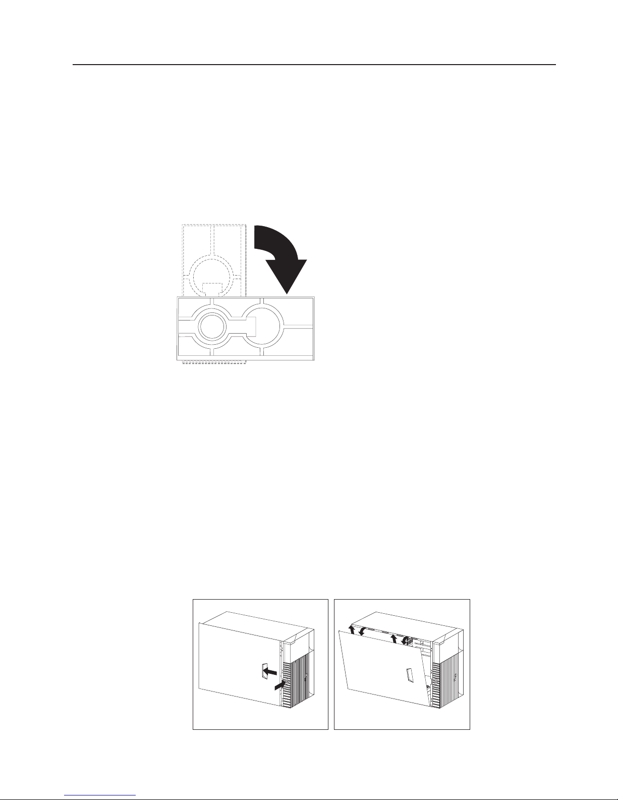
Installing options
This section provides instructions for installing various options in the computer.
Moving the stabilizing feet
The two front feet on the bottom of the computer rotate 90 degrees to provide
additional stability.
When installing options in the computer, you might find it easier to lay the computer
on its side. If you do so, rotate the feet in towards the computer, so they do not
break off due to the weight of the computer.
Removing the cover and front bezel
The following information describes how to remove the cover and bezel from the
computer. When disconnecting cables, be sure to note where they attach, so that
you can correctly reattach them correctly later.
To remove the cover and front bezel, complete the following steps:
1. Review the information in “Before you begin” on page 43.
2. Remove any media (diskettes, CDs, or tapes) from the drives, and shut down
the operating system.
3. Turn off the computer and all attached devices. Disconnect all external cables
and power cords.
4. If the key-lock button is locked, unlock it.
5. Press the key-lock button on the left side of the front bezel, and slide the side
cover toward the rear of the computer.
6. Lift the side cover from the computer.
Installing options 47
Page 58

7. Lift the lever at the top of the chassis and pull the front bezel from the front of
the computer. Yo u might need to move the computer closer to the edge of the
desk to completely rotate the bezel down to remove it.
Attention: Proper cooling is required for the reliable performance of internal
components. Do not operate the computer with the cover removed.
Removing the air baffle
The computer might come with a plastic air baffle that directs air flow through the
processor. When installing options, you might need to lift the air baffle out of the
chassis to access some components. Place the baffle back into place before
replacing the cover.
To remove the air baffle, do the following:
1. Pull the blue clip outward until the pins disengage.
48 Hardware Maintenance Manual: IBM IntelliStation M Pro Type 6233 and 6850
Page 59

2. Slide the air baffle back slightly and lift it to remove it.
Working with adapters
You can install a variety of adapters in the expansion slots on the system board.
For help in locating the system board, see “Major components of the IntelliStation M
Pro Types 6850 and 6233” on page 41.
Note: The computer power supply might not be able to support the installation of
an adapter in all PCI slots. The ability of the power supply to support an
adapter in all slots is dependent on the computer configuration and the type
of PCI adapter installed.
You can install various adapters in the expansion slots in the computer. The AGP
Pro video adapter is installed in the AGP slot. Yo u can install up to five PCI
adapters in PCI expansion slots. There are three 32-bit PCI slots and two 64-bit
slots.
Note: Because of its width, the Wildcat III 6110 video adapter requires both the
AGP slot and the adjacent PCI slot. If your model contains this video
adapter, be careful when you install an adapter in PCI slot 2 because the
space between the Wildcat III 6110 adapter and PCI slot 2 is very limited,
which causes the adapters to be very close to each other.
The following illustration shows the location of the AGP and PCI expansion slots on
the system board.
Note: The illustrations in this document might differ slightly from your hardware.
Installing options 49
Page 60

PCI slot 1
PCI slot 2
PCI slot 3
PCI slot 4
PCI slot 5
AGP Pro connector
Adapter considerations
Before you install adapters, read the following:
v Review the documentation that comes with the adapter, and follow those
instructions in addition to the instructions given in this chapter.
v You can install full-length adapters in all five PCI expansion slots.
v The computer supports 5.0V and 3.3V PCI adapters. The 32-bit adapter slots
support 5.0V PCI adapters and the 64-bit slots support 3.3V adapters.
The computer power supply might not be able to support the installation of
Note:
an adapter in all PCI slots. The ability of the power supply to support an
adapter in all slots is dependent on the computer configuration and the type
of PCI adapter installed.
Installing an adapter
Attention: When you handle static-sensitive devices, take precautions to avoid
damage from static electricity. For details on handling these devices, refer to
“Handling static-sensitive devices” on page 43.
To install an adapter, complete the following steps:
1. Review the “Safety information” on page 103.
2. Turn off the computer and peripheral devices.
3. Remove all external cables from the computer; then remove the cover. For
more information, see “Removing the cover and front bezel” on page 47.
4. Determine which PCI expansion slot you will use for the adapter.
5. If you are installing a full-sized adapter in one of the PCI slots on the system
board, rotate the PCI support bracket out of your way.
50 Hardware Maintenance Manual: IBM IntelliStation M Pro Type 6233 and 6850
Page 61

6. Remove the PCI adapter retention bracket or the adapter retention screw
(depending on the model) from the rear of the system and remove the
expansion slot cover.
7. Touch the static-protective package containing the adapter to any unpainted
metal surface in the computer; then, remove the adapter from the package.
8. Install the adapter in the expansion slot.
9. Replace the PCI adapter retention bracket or adapter retention screw
(depending on the model).
10. Rotate the PCI adapter support bracket back into place.
11. Replace the cover, see “Replacing the cover and connecting the cables” on
page 65.
Installing options 51
Page 62

Adapters supported by the computer use Plug and Play technology, which enables
the computer to automatically configure the adapter. For more information, see
“Updating the computer configuration” on page 71.
Installing internal drives
Different types of drives enable the computer to read multiple types of media and
store data in different formats. Depending on the computer model, you might have
one or more of the following drives installed.
v CD-ROM drive
v Diskette drive
v Hard disk drive
Internal drive bays
The IBM IntelliStation M Pro computer comes with an IDE CD-ROM drive installed
in bay 2, a 3.5-inch, 1.44 MB diskette drive (2 mode) installed in bay 3, a SCSI
hard disk drive installed in bay 9 in SCSI models, and an IDE hard disk drive
installed in bay 5 in IDE models. The computer has a static shield and bay panel
installed in bay 1.
Note: The illustrations in this document might differ slightly from your hardware.
Drive bay 1
Drive bay 2 (CD-ROM drive)
Drive bay 3 (diskette drive)
Drive bay 4
Drive bay 5
Drive bay 6
Drive bay 7
Drive bay 8
Drive bay 9 (hard disk drive)
Drive specifications
The following table describes some of the drives you can install in each bay and
their height requirements.
52 Hardware Maintenance Manual: IBM IntelliStation M Pro Type 6233 and 6850
Page 63

Bay number Type of drive
Bay 1 - Maximum height: 25.4 mm (1.0 in.)
Bay 2 - Maximum height: 25.4 mm (1.0 in.) CD-ROM drive (preinstalled)
Bay 3 - Maximum height: 25.4 mm (1.0 in.) 3.5-inch diskette drive (preinstalled)
Bay 4 - Maximum height: 25.4 mm (1.0 in.) 3.5-inch hard disk drive
Bay 5 - Maximum height: 25.4 mm (1.0 in.) 3.5-inch hard disk drive (preinstalled in bay 5
Bay 6 - Maximum height: 25.4 mm (1.0 in.) 3.5-inch hard disk drive
Bay 7 - Maximum height: 25.4 mm (1.0 in.) 3.5-inch hard disk drive
Bay 8 - Maximum height: 25.4 mm (1.0 in.) 3.5-inch hard disk drive
Bay 9 - Maximum height: 25.4 mm (1.0 in.) 3.5-inch hard disk drive (preinstalled in bay 9
v Tape drive
v DVD
v Jaz drive
v Zip drive (bracket required)
v CD-RW
on IDE models)
on SCSI models)
Notes:
1. Install removable-media drives in bay 1.
2. The computer supports only one diskette drive (bay 3).
3. IDE models are shipped with an IDE hard disk drive in bay 5. If you upgrade,
install the second hard disk drive in bay 4.
4. The computer supports up to four IDE hard disk drives. Install the first two hard
disk drives in bay 4 and bay 5. Yo u can install two more hard disk drives in
bays 6 and 7 by removing the CD-ROM drive connection.
5. SCSI models are shipped with a SCSI hard disk drive in bay 9. If you upgrade,
install the next hard disk drive in bay 8; then, bays 7, 6, 5, and 4 (in this order).
Before you install hard disk drives in the computer, verify that you have all the
cables and other equipment specified in the documentation that comes with the
hard disk drive. You might also need to perform certain preinstallation activities.
Some of the steps are required only during the initial installation of an option.
SCSI Controller
The computer is equipped with a SCSI controller integrated on the system board for
use with Ultra160 SCSI devices.
If the computer has preinstalled software, you can find information about the SCSI
controller and connecting devices by clicking Start --> Access IBM--> Get help -->
View documentation. SCSI documentation is also on the Software Selections CD
that comes with the computer.
Power and signal cables for internal drives
The computer uses cables to connect internal drives to the power supply and
system board. The drives that are preinstalled in the computer come with power
and signal cables attached. If you replace any drives, it is important to remember
which cable is attached to which drive. The following cables are provided:
v Four-wire power cables connect most drives to the power supply. At the end of
these cables are plastic connectors that attach to different drives; these
connectors vary in size. Also, certain power cables attach to the system board.
Installing options 53
Page 64

v Flat signal cables, also called ribbon cables, connect SCSI, IDE, and diskette
drives to the system board.
– The wider gray signal cable has three connectors. One of these connectors
attaches to the CD-ROM drive, one is available for a device installed in bay 1,
and one attaches to the secondary IDE connector on the system board.
– The narrower gray signal cable has two connectors for attaching the diskette
drive to the diskette-drive connector on the system board.
– An Ultra160 twisted ribbon cable connects the internal Ultra160 SCSI hard
disk drive to the SCSI connector on the system board. This cable has five
additional connectors for attaching more internal SCSI devices.
– A round SCSI cable connects external SCSI devices to the SCSI connector on
the system board and provides an additional connector for a SCSI device
installed in bay 1. If a SCSI device is installed in bay 1 but no external SCSI
devices are attached, a SCSI terminator must be attached to the external
SCSI connector. For more information on connecting SCSI devices, see the
Adaptec SCSI documentation on the Software Selections CD that comes with
the computer.
To locate connectors on the system board, see “System board connectors”
Note:
on page 42.
Considerations
for cabling IDE internal drives: The following are some
important points to remember when connecting IDE internal drives:
v When you install a hard disk drive, ensure that the drive connector at the end of
the signal cable is always connected to a drive; also, ensure that the drive
connector at the other end is connected to the system board. This reduces
electronic noise from the computer.
v IDE models ship with a gray ATA100 cable. Attach the blue connector to the
primary IDE connector on the system board, attach the black connector to the
master hard disk drive, and attach the gray connector to the subordinate hard
disk drive.
v If two IDE devices are used on a single cable, one must be designated as the
master device and the other as the subordinate device; otherwise, the system
might not recognize some of the IDE devices. Switch or jumper settings on each
IDE device determine the master or subordinate designation.
v If two IDE devices are on a single cable and only one is a hard disk drive, the
hard disk drive must be set as the master device.
v If you have only one IDE device on a cable, it must be set as master.
Preinstallation steps
Before you install hard disk drives in the computer, verify that you have all the
cables and other equipment specified in the documentation that comes with the
hard disk drive. You might also need to perform certain preinstallation activities.
Some of the steps are required only during the initial installation of an option.
1. Read the “Safety information” on page 103, “Handling static-sensitive devices”
on page 43, and the documentation that comes with the drive.
2. Choose the bay in which you want to install the drive.
3. Check the instructions that come with the drive to see if you need to set any
switches or jumpers on the drive. If you are installing a SCSI device, be sure to
set the SCSI ID for that device.
54 Hardware Maintenance Manual: IBM IntelliStation M Pro Type 6233 and 6850
Page 65
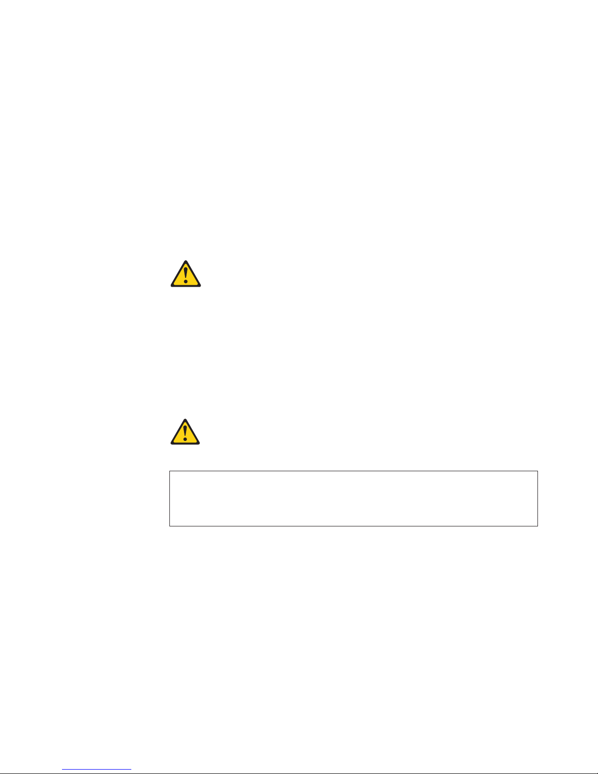
Installing a drive in bay 1
Before you begin, do the following:
Attention: When you handle static-sensitive devices, take precautions to avoid
damage from static electricity. For details on handling these devices, refer to
“Handling static-sensitive devices” on page 43.
v For information on installing SCSI drives, see the SCSI information on the
Software Selections CD that comes with the computer.
v Review the “Safety information” on page 103.
v Read the documentation that comes with the hard disk drive.
v Turn off the computer and all peripheral devices.
v Disconnect all external cables and power cords; then, remove the computer side
cover. See “Removing the cover and front bezel” on page 47.
Statement 3
CAUTION:
When laser products (such as CD-ROMs, DVD-ROM drives, fiber optic
devices, or transmitters) are installed, note the following:
v Do not remove the covers. Removing the covers of the laser product could
result in exposure to hazardous laser radiation. There are no serviceable
parts inside the device.
v Use of controls or adjustments or performance of procedures other than
those specified herein might result in hazardous radiation exposure.
DANGER:
Some laser products contain an embedded Class 3A or Class 3B laser diode. Note
the following:
Laser radiation when open. Do not stare into the beam, do not view directly with
optical instruments, and avoid direct exposure to the beam.
To install a drive in drive bay 1, do the following:
Note: You need an industry standard bay adapter bracket to install a 3.5-inch hard
disk drive in drive bay 1.
1. Touch the static-protective package containing the new drive to any unpainted
metal surface in the computer; then, remove the drive from the package.
2. Remove the EMC shield covering drive bay 1 and insert the drive into the empty
drive bay. Then, tighten the screws to hold the drive in place.
Installing options 55
Page 66

3. Attach all cables to the hard disk drive.
4. If the drive is a removable media drive, remove the front bay panel in the cover.
5. Replace the side cover and reconnect the external cables and power cords. See
“Replacing the cover and connecting the cables” on page 65.
Installing drives in drive bays 4, 5, 6, 7, and 8
Before you begin, do the following:
Note: For IDE models, there are only four hard disk drives supported. The IDE
models are shipped with a hard disk drive installed bay 5. If you upgrade,
install hard disk drives in bay 4, 6, and 7 (in this order).
v SCSI models are shipped with a hard disk drive installed in bay 9. If you
upgrade, install hard disk drives in bay 8, 7, 6, 5, and 4 (in this order).
v For information on installing SCSI drives, see the SCSI information on the
Software Selections CD that comes with the computer.
v Review the “Safety information” on page 103.
v Read the documentation that comes with the hard disk drive.
v Turn off the computer and all peripheral devices.
v Disconnect all external cables and power cords; then, remove the computer side
cover. See “Removing the cover and front bezel” on page 47.
install a drive in drive bays 4, 5, 6, 7, and 8, do the following:
To
1. Touch the static-protective package containing the new drive to any unpainted
metal surface in the computer; then, remove the drive from the package.
2. Get two sliding rail mounts from the plastic bag located underneath the hard
disk drive cage.
3. Mount the sliding rails on the hard disk drive you want to install.
56 Hardware Maintenance Manual: IBM IntelliStation M Pro Type 6233 and 6850
Page 67

4. Slide the hard disk drive along the rail guides into the drive bay.
5. Attach all cables to the drive.
6. Replace the side cover and reconnect the external cables and power cords. See
“Replacing the cover and connecting the cables” on page 65.
Installing memory modules
Adding memory to the computer is an easy way to make programs run faster. You
can increase the amount of memory in the computer by installing options called
memory modules.
The computer has eight connectors for installing Rambus inline memory modules
(RIMMs). The IBM-installed RIMMs that come with the computer are ECC (error
checking and correction) RDRAM (Rambus dynamic random access memory)
modules.
RIMM 1
RIMM 3
RIMM 5
RIMM 7
RIMM 6
RIMM 8
RIMM 2
RIMM 4
Voltage regulator module
(VRM1)
Installing options 57
Page 68

RIMM pairing is as follows:
v Pair 1 includes RIMM 1 and RIMM 2.
v Pair 2 includes RIMM 3 and RIMM 4.
v Pair 3 includes RIMM 5 and RIMM 6.
v Pair 4 includes RIMM 7 and RIMM 8.
installing or replacing RIMMs, note the following:
When
v The memory board in the computer has eight RIMM connectors arranged in
pairs. RIMMs must be installed in matched pairs. This means that the RIMMs
installed in a RIMM connector pair must be the same speed, size, and
technology. For example, you can install a pair of 144Mbit, ECC, 400MHz, 128
MB RIMMs in RIMM 1 and RIMM 2 slots. You cannot install a pair that has one
144Mbit, ECC, 400MHz, 128 MB RIMM in RIMM 1 and one 288Mbit, ECC,
400MHz, 256 MB RIMM in RIMM 2, or vice versa. When you want to upgrade
with another pair of RIMMs, you can install either a pair of 128 MB RIMMs, a pair
of 256 MB RIMMs, or a pair of 512 MB RIMMs (as long as they are of the same
speed, size, and technologies).
v The memory board in the computer has eight RIMM connectors, pairs 1 and 2
must have RIMMs or continuity RIMMs (C-RIMMs) installed in them. For the
arrangement of the RIMM connector pairs on the computer memory board, see
the following table.
Refer to the following sequence examples for upgrading memory. For these
examples, we use 144Mbit, ECC, 400MHz, 128 MB, 256 MB, and 512 memory
modules:
Sequence 1
The computer is shipped with a pair of 128 MB RIMMs installed in RIMM
1 and RIMM 2 connectors and a pair of C-RIMMs installed in RIMM 3
and RIMM 4. All other RIMM connectors are empty.
Sequence 2
The first upgrade with a pair of 256 MB RIMMs. Remove the C-RIMMs
from RIMM 3 and RIMM 4 connectors, and insert them in RIMM 7 and
RIMM 8 connectors. Install the new pair of RIMMs in RIMM 3 and RIMM
4 connectors. RIMM 5 and RIMM 6 connectors remain empty.
Sequence 3
The second upgrade with a pair of 512 MB RIMMs. Remember, you can
mix and match memory modules as long as a pair is of the same size,
speed, and technology. Install the pair of 512 MB RIMMs in RIMM 5 and
RIMM 6 connectors. No other changes need to be made.
Sequence 4
The third upgrade with a pair of 128 MB RIMMs. Remove the C-RIMMs
from RIMM 7 and RIMM 8 (keep the C-RIMMs for future use). Install the
new pair of RIMMs into RIMM 7 and RIMM 8 connectors.
C-RIMMs (termination card) must be populated for unused RIMM slots within the
v
same paired channel.
v C-RIMMs are not needed if the RIMM connectors of the paired channel do not
populate any RIMMs.
v Install only ECC RIMMS to enable ECC.
v Do not mix RIMM speed, technologies, density, non-ECC and ECC memory
within a pair of RIMMs. This is not supported.
v RIMM connectors do not support dual inline memory modules (DIMMs).
v Use only PC800, 400 MHz RIMMs.
58 Hardware Maintenance Manual: IBM IntelliStation M Pro Type 6233 and 6850
Page 69

v Use only 144 Mbit or 288 Mbit technologies.
v The memory must be installed in matched pairs. To ensure that the RIMM pair
match, use RIMMs with identical option part numbers (shown on RIMM labels).
the following table to help you to configure a memory card with eight RIMM
Use
connectors.
Pair 1 Pair 2 Pair 3 Pair 4
RIMM 1 RIMM 2 RIMM 3 RIMM 4 RIMM 5 RIMM 6 RIMM 7 RIMM 8
2 RIMMs RIMM RIMM C-RIMM C-RIMM Empty Empty Empty Empty
4 RIMMs RIMM RIMM RIMM RIMM Empty Empty C-RIMM C-RIMM
6 RIMMs RIMM RIMM RIMM RIMM RIMM RIMM C-RIMM C-RIMM
8 RIMMs RIMM RIMM RIMM RIMM RIMM RIMM RIMM RIMM
Notes:
1. The IBM IntelliStation M Pro computer supports 128 MB, 256 MB, and 512 MB
RIMMs. The computer supports a minimum of 256 MB and a maximum of 4 GB
of system memory. Refer to http://www.ibm.com/pc/support for a list of memory
modules for use with the computer.
2. Installing or removing RIMMs changes the configuration information in the
computer. Therefore, after installing or removing a RIMM, you must change and
save the new configuration information by using the Configuration/Setup Utility
program. When you restart the computer, the system displays a message
indicating that the memory configuration has changed. Yo u must start the
Configuration/Setup Utility program and select Save Settings to save your
changes. See “Configuration” on page 33 for more information.
3. The illustrations in this documentation might differ slightly from your computer.
Removing a RIMM or C-RIMM
Complete the following steps to remove a RIMM or C-RIMM:
Attention: When you handle static-sensitive devices, take precautions to avoid
damage from static electricity. For details on handling these devices, refer to
“Handling static-sensitive devices” on page 43.
1. Review the “Safety information” on page 103.
2. Turn off the computer and all attached devices.
3. Disconnect all external cables and power cords from the computer, and remove
the computer cover (see “Removing the cover and front bezel” on page 47).
4. If the computer comes with an air baffle, you might need to lift it out to access
parts of the system board. See “Removing the air baffle” on page 48 for more
information.
5. Remove the PCI adapter retention bracket or the memory board retention screw
(depending on the model).
6. Rotate the front adapter support bracket out of the way and pull the memory
board out of the chassis.
7. At both ends of the RIMM connector on the memory board, push outward on
the retaining clips until the module is loosened. Lift the RIMM or C-RIMM out of
the connector.
Attention: Be careful not to push too hard on the retaining clips, because the
RIMM or C-RIMM might eject too quickly.
Installing options 59
Page 70

8. Store the RIMM or C-RIMM in a static-protective package. Do not discard or
lose this part. It might be needed later if you change the memory configuration.
Installing a RIMM or C-RIMM
Complete the following steps to install a RIMM or C-RIMM:
1. Read the instructions that come with the new system memory.
2. Turn off the computer and all attached devices.
3. Disconnect all external cables and power cords from the computer and remove
the computer cover (see “Removing the cover and front bezel” on page 47).
4. Remove any C-RIMMs that are in the slots where you want to add RIMMs.
5. Touch the static-protective package containing the RIMM to any unpainted
metal surface on the computer. Then remove the RIMM or C-RIMM from the
package.
6. Install the RIMMs in the next highest numbered RIMM slots.
7. Position the RIMM or C-RIMM above the connector so that the two notches on
the bottom edge of the module align properly with the empty connector.
Note: Pay attention to the orientation of the notches on the connectors and
RIMMs. Adjacent connectors might not have the same orientation on
the memory board.
8. Firmly push the module straight down into the connector until the retaining
clips pop up and fit snugly around both ends of the module.
Notches
9. Place the memory board into the MEC connector on the system board.
10. Replace the PCI adapter retention bracket.
60 Hardware Maintenance Manual: IBM IntelliStation M Pro Type 6233 and 6850
Page 71

11. To replace the cover, see “Replacing the cover and connecting the cables” on
page 65.
12. Reconnect the external cables and power cords; then, turn on the attached
devices and the computer.
Installing a microprocessor
Before you install a second microprocessor on a computer with a preinstalled
operating system, do the following:
Notes:
1. Always check the IBM web site at http://www.ibm.com/pc/support for the latest
level of diagnostics code before running the diagnostic program.
2. Be sure to check the cache size, type, and speed of the microprocessor that is
currently in the computer before installing a second microprocessor. The second
microprocessor must be of the same cache size, type, and speed as the
microprocessor currently in the computer. Do not install two microprocessors of
different cache size, type, and speed.
Use the System Summary option on the Configuration/Setup Utility main menu
to view the processor speed and other information about the computer. For
information on how to start the Configuration/Setup Utility and additional
information on configuring the computer, see “Configuration” on page 33.
Installing a second microprocessor on Windows NT
If Windows NT is preinstalled on the computer, follow these steps:
1. Backup the hard disk.
2. Run the Multiprocessor Upgrade Option program, addcpu.exe, located at
http://www.ibm.com/pc/support before you install the second microprocessor.
From the IBM support page, type addcpu in the Search field and press Enter.
In addition, download and read the addcpu.pdf file for instructions on adding a
second microprocessor.
3. Continue with step 1 of “Second microprocessor installation” on page 62.
Installing a second microprocessor on Windows 2000
If Windows 2000 is preinstalled on the computer, follow these steps:
Note: Be sure to check the Microsoft web page at http://www.microsoft.com for
updates to these instructions. From the Microsoft web page, type
multiprocessor support in the Search field and press Enter.
1. Backup the hard disk.
2. Do the following:
a. From the desktop, click Start--->Settings--->Control Panel.
b. On the Control Panel window, double-click the System icon.
c. On the System Properties window, select the Hardware tab; then, click the
Device Manager button.
d. On the Device Manager window, click on the plus sign (+) next to the
Computer node to expand the list; then, double-click on ACPI Uniprocessor
PC.
e. On the Advanced Configuration and Power Interface (ACPI) PC Properties
window, select the Driver tab; then, click the Update Driver button.
f. On the Update Device Driver Wizard window, click Next.
Installing options 61
Page 72

g. On the next window, click the Display a known list of drivers for this
device so that I can choose a specific driver radio button; then, click
Next.
h. On the next window, click the Show all hardware of this device class
radio button. Under the Models field, select ACPI Multiprocessor PC; then,
click Next .
i. If the configuration shown in the wizard is satisfactory, click Next to save the
configuration.
j. Click Finish to complete the process.
k. When prompted as to whether you want to restart the computer, select Yes.
Continue with step 1 of “Second microprocessor installation.”
3.
Second microprocessor installation
To install a second microprocessor, do the following:
Attention: When you handle static-sensitive devices, take precautions to avoid
damage from static electricity. For details on handling these devices, refer to
“Handling static-sensitive devices” on page 43.
1. Read the instructions that come with the new microprocessor.
2. Turn off the computer and all attached devices.
3. Disconnect all external cables and power cords from the computer and remove
the computer cover (see “Removing the cover and front bezel” on page 47).
4. Lay the computer on its side for better access to the computer components.
5. Remove the memory board.
6. If the computer has an air baffle, remove it (see “Removing the air baffle” on
page 48).
7. See the system board label inside the computer for the location of the second
microprocessor socket (CPU).
8. Remove the screws from the plastic microprocessor cover; then, remove the
plastic microprocessor cover (keep the cover for future use).
Note: Some models have the plastic microprocessor cover attached to the air
baffle. If this is the case, you must remove the air baffle and
microprocessor together, after removing the screws for the plastic
microprocessor cover.
9. Touch the static-protective package containing the microprocessor to any
unpainted metal surface on the computer. Then, remove the microprocessor
from the package.
10. Rotate the locking lever on the microprocessor socket from its closed and
locked position until it stops or clicks in the fully open position (approximately
135° angle), as shown. Then, see the documentation provided with the
microprocessor option for complete installation instructions.
Attention: Yo u must ensure that the locking lever on the microprocessor
socket is in the fully open position before you insert the microprocessor in the
socket. Failure to do so might result in permanent damage to the
microprocessor, microprocessor socket, and system board.
62 Hardware Maintenance Manual: IBM IntelliStation M Pro Type 6233 and 6850
Page 73

Lever open
Lever closed
Lever open
Lever closed
11. Insert the microprocessor in the microprocessor socket, lining pin number 1 up
with the microprocessor.
12. Rotate the microprocessor socket lever down to secure the microprocessor in
place.
13. Touch the static-protective package containing the heatsink to any unpainted
metal surface on the computer. Then, remove the heatsink from package.
14. Remove the plastic cap from the bottom of the heatsink. Do not touch the
bottom of the heatsink or sit the heatsink down after you remove the plastic
cap.
Notes:
a. Removing the heatsink from the microprocessor or setting the heatsink
down onto any surface when the protective cap is removed from the
heatsink can cause the thermal grease on the bottom of the heatsink to
become contaminated.
b. Do not touch the thermal grease on the bottom of the heatsink prior to
installing the heatsink.
Ensure that you place the heatsink on top of the microprocessor correctly and
15.
press firmly.
Installing options 63
Page 74

Heatsink
Positioning notch
Microprocessor
cover
Microprocessor
Microprocessor
socket
Microprocessor
lever
16. When you tighten the screws to secure the heatsink, alternate between the two
screws. That is, tighten one screw a little then tighten the other screw a little.
Continue switching between the screws until the heatsink is secured to the
microprocessor. Alternating the tightening of the screws can help prevent
damage to the microprocessor.
Attention: Ensure that the screws are completely tightened, otherwise, the
system will not function properly.
17. Reinstall the air baffle.
18. Reinstall the memory board.
19. Replace the cover (see “Replacing the cover and connecting the cables” on
page 65).
Security U-bolt
To help prevent hardware theft, a security U-bolt is attached to the chassis of the
computer. To secure the computer, thread a security cable through the U-bolt and
around an object that is a not part of or permanently secured to the building
structure or foundation, and from which it cannot be removed; then, fasten the cable
ends together with a lock. Ensure that the security cable does not interfere with
other cables that are connected to the computer.
64 Hardware Maintenance Manual: IBM IntelliStation M Pro Type 6233 and 6850
Page 75

Replacing the cover and connecting the cables
This section provides instructions on how to replace the cover and connect the
cables on the computer.
Note: The illustrations in this document might differ slightly from the hardware.
Complete the following steps to replace the cover and connect the cables:
1. Review the “Safety information” on page 103.
2. Ensure that all components have been reassembled correctly, and that no tools
or loose screws are left inside the computer.
3. Clear any cables that might impede the replacement of the cover.
4. Place the front bezel back onto the front of the chassis and snap it into place.
5. Slide the side cover into place on the chassis and lock the key-lock button.
6. Reconnect the external cables and power cords to the computer; then, plug the
power cords into properly grounded electrical outlets. Turn on the attached
devices and the computer.
7. Update the computer configuration. See “Updating the computer configuration”
on page 71.
If an error message related to the chassis-intrusion detector appears after
Note:
you restart the computer, you must type the administrator password. For
more information, see “Using passwords” on page 36.
Installing options 65
Page 76

Input/output connector locations
The following illustrations show the input/output connectors and the expansion slots
on the rear of the computer.
Power
connector
Mouse
connector
Keyboard
connector
Parallel
connector
USB
connectors
Serial
connector 1
Serial
connector 2
Ethernet
connector
Audio line out/
headphone connector
Audio line in
connector
Microphone in
connector
SCSI connector
Monitor connector
This section provides information about the I/O connectors on the rear of the
computer. These connectors include the following:
v One mouse
v One keyboard
v One parallel
v Two USB
v Two serial
v One Ethernet
v Audio
– Line out
– Line in
– Mic
One video
v
66 Hardware Maintenance Manual: IBM IntelliStation M Pro Type 6233 and 6850
Page 77

Mouse connector
The system board has one mouse connector that supports a mouse or other
pointing device. The mouse connector is located on the rear of the computer. See
“Input/output connector locations” on page 66 for its location.
Keyboard connector
There is one keyboard connector on the rear of the computer. See “Input/output
connector locations” on page 66 for its location.
Note: If you attach a standard (non-USB) keyboard to the keyboard connector, the
6
4
2
5
3
1
USB connectors and devices will be disabled during the power-on self-test.
6
4
2
5
3
1
Parallel connector
The computer has one parallel connector. This connector supports three standard
Institute of Electrical and Electronics Engineers (IEEE) 1284 modes of operation:
standard parallel port (SPP), enhanced parallel port (EPP), and extended capability
port (ECP).
Viewing or changing the connector assignments
You can use the built-in Configuration/Setup Utility program to configure the parallel
connector as bidirectional; that is, so that data can be both read from and written to
a device. In bidirectional mode, the computer supports the ECP and EPP modes.
Complete the following steps to view or change the parallel-connector assignment.
1. Restart the computer and watch the monitor screen.
2. When the message Press F1 for Configuration/Setup appears, press F1.
3. When the Configuration/Setup Utility menu appears, select Devices & I/O
4. Select the parallel connector; then, use the arrow keys to advance through the
5. Press Esc twice to return to the Configuration/Setup main menu; then, select
Ports; then, press Enter.
settings available.
Note: When you configure the parallel connector as bidirectional, use an IEEE
1284-compliant cable. The cable must not exceed 3 meters (9.8 feet).
Save & Exit Setup to exit from the Configuration/Setup Utility program.
Installing options 67
Page 78

Parallel connector
There is a 25-pin, female D-shell parallel connector on the rear of the computer.
See “Input/output connector locations” on page 66 for the location of this connector.
13
1
Serial connectors
The computer has two standard serial connectors: serial connector A and serial
connector B.
Some application programs require specific connectors, and some modems function
properly only at certain communication connector addresses. Yo u might need to use
the Configuration/Setup Utility program to change communication connector
address assignments to prevent or resolve address conflicts.
Viewing or changing the serial-connector assignments
Complete the following steps to view or change the serial-connector assignments.
1. Restart the computer and watch the monitor screen.
2. When the message Press F1 for Configuration/Setup appears, press F1.
3. When the Configuration/Setup Utility menu appears, select Devices & I/O
4. Select the serial connector; then, use the arrow keys to advance through the
5. Press Esc twice to return to the Configuration/Setup Utility main menu; then,
Serial connectors
There are two 9-pin, male D-shell serial connectors located on the rear of the
computer. See “Input/output connector locations” on page 66 for their locations.
25
14
Ports; then, press Enter.
available settings.
select Save & Exit Setup to exit from the Configuration/Setup Utility program.
1
5
Ethernet connector
The computer comes with an integrated Ethernet controller. This controller provides
an interface for connecting to 10-MBps or 100-MBps networks and provides
full-duplex capability, which enables simultaneous transmission and reception of
data on the Ethernet LAN.
To access the Ethernet connector, attach a Category 3, 4, or 5 unshielded
twisted-pair (UTP) cable to the RJ-45 connector on the rear of the computer. See
“Input/output connector locations” on page 66 for its location.
Note: The 100BASE-TX Fast Ethernet standard requires that the cabling in the
network be Category 5.
68 Hardware Maintenance Manual: IBM IntelliStation M Pro Type 6233 and 6850
69
Page 79

Configuring the Ethernet controller
When you connect the computer to the network, the Ethernet controller
automatically detects the data-transfer rate (10 MBps or 100 MBps) on the network
and then sets the controller to operate at the appropriate rate. In addition, if the
Ethernet connector that the computer is connected to supports auto-negotiation, the
Ethernet controller will set the appropriate duplex state. That is, the Ethernet
controller will adjust to the network data rate, whether the data rate is standard
Ethernet (10BASE-T), Fast Ethernet (100BASE-TX), half duplex (HDX), or full
duplex (FDX). The controller supports HDX and FDX modes at both speeds.
The Ethernet controller is integrated on the system board. You do not need to set
any jumpers or configure the controller for the operating system before you use the
Ethernet controller. However, you must install a device driver to enable the
operating system to address the Ethernet controller. The device drivers are provided
on the preinstalled software and the Device Drivers and IBM Enhanced Diagnostics
CD.
Ethernet connector
There is an RJ-45 connector on the rear of the computer. See “Input/output
connector locations” on page 66 for the location of this connector.
Universal Serial Bus connectors
The computer has two Universal Serial Bus (USB) connectors, which are configured
automatically. USB is a serial interface standard for telephony and multimedia
devices. It uses Plug and Play technology to determine the type of device that is
attached to the connector.
Notes:
1. If you attach a standard (non-USB) keyboard to the keyboard connector, the
USB connectors and devices will be disabled during the power-on self-test.
2. If you install a USB keyboard that has a mouse connector, the USB keyboard
emulates a mouse, and you will not be able to disable the mouse settings in the
Configuration/Setup Utility program.
USB cables and hubs
You need a 4-pin cable to connect devices to USB 2 or USB 3. If you plan to attach
more than two USB devices, you must use a hub to connect the devices. The hub
provides multiple connectors for attaching additional external USB devices.
USB technology transfers data at up to 12 megabits-per-second (MBps) with a
maximum of 127 external devices and a maximum signal distance of five meters
(16 ft.) per segment.
8
1
Installing options 69
Page 80

USB connectors
There are two USB connectors on the rear of the computer for attaching USB
compatible devices. See “Input/output connector locations” on page 66 for the
location of the USB connectors.
Audio connectors
The audio connectors are used to connect external audio equipment to the
computer. See “Input/output connector locations” on page 66 for the location of
these connectors.
14
Line
out
Line
in
Line out
This connector is used to send audio signals from the computer to external devices,
such as powered speakers with built-in amplifiers, headphones, multimedia
keyboards, or the audio Line in connector on a stereo system.
Line in
This connector is used to accept audio signals from external devices, such as line
output from a stereo, television, or musical instrument into the computer sound
system.
Mic
This connector is used to connect a microphone to the computer when you want to
record voice or other sounds on the hard disk drive. It can also be used by speech
recognition software.
Video connector
The computer uses an AGP video adapter located in the AGP Pro slot on the
system board. The video connector is located on the adapter on the rear of the
computer. See “Input/output connector locations” on page 66 for the location of this
connector.
Analog video connector:
5
1
Mic
1115
Digital (DVI-I) video connector:
1
C1 C2
C3C5C4
Low force helical-60 (LFH-60) video connector:
70 Hardware Maintenance Manual: IBM IntelliStation M Pro Type 6233 and 6850
Page 81

Some models come with an AGP adapter that has dual video connectors. If you
have problems viewing information with a second monitor, see “Changing monitor
settings” on page 11.
Models with the Wildcat III 6110 and Fire GL 8800 video adapter come with DVI-I to
VGA style analog converters for each DVI-I connector.
Attention: On the Wildcat III 6110 video adapter, the first or only monitor must be
connected to the bottom connector (connector number 1).
Models with the Matrox G450 DVI-I video adapter come with a DVI-I to dual-analog
monitor pigtail cable.
Models with the NVIDIA Quadro4 200NVS video adapter come with a low force
helical-60 (LFH-60) to dual-analog monitor pigtail cable. If you want to setup two
digital monitors, you will need to purchase a separate dual-digital monitor cable.
Completing the installation
After working with options, you need to reinstall any removed parts, replace the
cover, and reconnect cables, such as power cords and monitor cables. Also,
depending on the option installed, you might need to update information in the
Configuration/Setup Utility program or install device drivers. For instructions on how
to install device drivers, see the instructions that come with the option. Some device
drivers are included on the Device Driver and IBM Enhanced Diagnostics CD that
comes with the computer.
Updating the computer configuration
Note: The configuration information in this section applies to installing options. For
more information on using the Configuration/Setup Utility program, see
“Using the Configuration/Setup Utility program” on page 33.
After adding options, you must update the configuration settings. In most cases,
system programs perform this configuration automatically. If the settings are not
updated automatically, you can use the Configuration/Setup Utility program to
reconfigure the appropriate settings. In either case, you must save the settings
before exiting from the Configuration/Setup Utility program.
For information on error messages from resource conflicts, see “Diagnostics” on
page 17 and “Symptom-to-FRU index” on page 83.
Configuring Plug and Play adapters
Adapters designed for PCI slots are Plug and Play devices. Plug and Play adapters
come with configuration specifications set in the operating system. These
specifications provide installation information to the computer during startup. When
you install or remove Plug and Play adapters, this information is interpreted by the
basic input/output system (BIOS) code, which supports Plug and Play technology. If
the required resources are available, the BIOS code automatically configures the
adapter using resources not used by other devices. The system board of the
computer supports operating systems that use Plug and Play technology.
For more information on error messages from resource conflicts, see “Diagnostics”
on page 17 and “Symptom-to-FRU index” on page 83.
Installing options 71
Page 82

Starting the Configuration/Setup Utility program
When you restart the computer for the first time after working with most options, a
message similar to the following might appear indicating that a configuration change
has occurred.
The following error(s) were detected when the system was started:
162 Configuration Changes Has Occurred
Select one of the following:
Continue
Exit Setup
If such a message appears, you are then prompted to start the Configuration/Setup
Utility program to manually update the configuration settings or to confirm and save
the settings that were automatically updated by the system programs.
Note: Depending on the configuration changes that occurred, the error message
you see might be different from the one shown here. If the preceding screen
appears, select Continue until you reach the Configuration/Setup Utility
program menu (see “Using the Configuration/Setup Utility program” on page
33.
If the preceding message does not appear, use the Configuration/Setup Utility
program to configure the computer.
Configuring startup sequence
When the computer is turned on and after it completes loading the BIOS code and
performs POST, it looks for an operating system. The order in which it searches
devices for the operating system is determined by the primary startup sequence or
the automatic startup sequence. After adding new devices to the computer, you
might want to change the startup sequence. Yo u can use the Configuration/Setup
Utility program to configure startup devices.
72 Hardware Maintenance Manual: IBM IntelliStation M Pro Type 6233 and 6850
Page 83

FRU information (service only)
Field Replacement Units (FRUs) should be replaced by qualified service personnel
only.
CD-ROM drive removal
Note: The illustrations in this documents might differ slightly from your hardware.
Note: Before performing any removals, read “Safety information” on page 103 and “Before
you begin” on page 43.
To remove the CD-ROM drive, do the following:
1. Power-off the system.
2. Remove the cover (see “Removing the cover and front bezel” on page 47).
3. Remove the cables.
4. Remove the (2) screws.
5. Gently slide the CD-ROM drive out
© Copyright IBM Corp. 2002 73
Page 84

Diskette drive
Note: The illustrations in this documents might differ slightly from your hardware.
Note: Before performing any removals, read “Safety information” on page 103 and “Before
you begin” on page 43.
To remove the diskette drive, do the following:
1. Power-off the system.
2. Remove the cover (see“Removing the cover and front bezel” on page 47).
3. Remove the cables.
4. Push the tab and slide the diskette drive outward.
74 Hardware Maintenance Manual: IBM IntelliStation M Pro Type 6233 and 6850
Page 85

Fan removal
Note: The illustrations in this documents might differ slightly from your hardware.
Note: Before performing any removals, read “Safety information” on page 103 and “Before
you begin” on page 43.
To remove the fan, do the following:
1. Power-off the system.
2. Unplug the system.
3. Remove the cover (see “Removing the cover and front bezel” on page 47).
4. Disconnect the fan from the system board.
5. Remove the full length PCI cards.
6. Remove the air duct by pushing the blue push pins (2) outward.
7. Pull the (2) blue push pins on the top corners of the assembly.
8. Lean fan bracket assembly towards rear of the computer and pull out.
FRU information (service only) 75
Page 86

LED/power switch removal
Note: The illustrations in this documents might differ slightly from your hardware.
Note: Before performing any removals, read “Safety information” on page 103 and “Before
you begin” on page 43.
To remove the LED/power switch, do the following:
1. Power-off the system.
2. Unplug the system.
3. Remove the cover (see “Removing the cover and front bezel” on page 47).
4. Remove the front bezel (see “Removing the cover and front bezel” on page 47).
5. Disconnect connector from planar.
6. Remove the LED/power switch screw.
7. Gently lift the LED/power switch up and out.
76 Hardware Maintenance Manual: IBM IntelliStation M Pro Type 6233 and 6850
Page 87

Memory board removal
Note: The illustrations in this documents might differ slightly from your hardware.
Note: Before performing any removals, read “Safety information” on page 103 and “Before
you begin” on page 43.
To remove the memory board, do the following:
1. Power-off the system.
2. Unplug the system.
3. Remove the cover (see “Removing the cover and front bezel” on page 47)
4. Disconnect all external cables and power cords from the computer.
5. Unscrew (1) the memory board.
6. Gently pull the memory board outward.
FRU information (service only) 77
Page 88

Power supply removal
Note: The illustrations in this documents might differ slightly from your hardware.
Note: Before performing any removals, read “Safety information” on page 103 and “Before
you begin” on page 43.
To remove the power supply, do the following:
1. Power-off the system.
2. Unplug the system.
Note: This procedure can be done easier by laying the system on its side.
3. Remove the cover (see “Removing the cover and front bezel” on page 47).
4. Disconnect cables from the system board and drives.
5. Disconnect the power supply cables from the system board.
6. Remove the screws (4) from the rear of the computer.
7. Gently move the power supply away from the chassis and lift it out of the
computer.
78 Hardware Maintenance Manual: IBM IntelliStation M Pro Type 6233 and 6850
Page 89

Speaker removal
Note: The illustrations in this documents might differ slightly from your hardware.
Note: Before performing any removals, read “Safety information” on page 103 and “Before
you begin” on page 43.
To remove the speaker, do the following:
1. Power-off the system.
2. Unplug the system.
3. Remove the cover (see “Removing the cover and front bezel” on page 47)
4. Disconnect the cables from system board.
5. Remove the front bezel.
6. Remove the speaker screws (2).
7. Gently pull the speaker outward.
FRU information (service only) 79
Page 90

System board removal
Notes:
1. When replacing the system board, you must either update the system with the
latest firmware or restore the pre-existing firmware that the customer provides
on a diskette or CD image.
2. The illustrations in this documents might differ slightly from your hardware.
Note: Before performing any removals, read “Safety information” on page 103 and “Before
you begin” on page 43.
To remove the system board, do the following:
1. Power-off the system
2. Remove the cover (see “Removing the cover and front bezel” on page 47)
Note: This procedure can be done easier by laying the system on its side.
3. Remove the memory board (see “Memory board removal” on page 77).
4. Remove the adapter cards.
5. Remove the air duct.
6. Remove the fan assembly.
80 Hardware Maintenance Manual: IBM IntelliStation M Pro Type 6233 and 6850
Page 91

7. Disconnect the cables.
Note: Be sure to disconnect the (2) cables that are connected to the SCSI
connectors underneath the fan assembly.
8. Removes (1) screw which fastens the metal system board backing plate to the
chassis.
9. Remove the system board backing plate from the chassis by pushing (2) blue
tabs toward the front of the computer.
10. Gently pull the system board with backing plate from the system.
FRU information (service only) 81
Page 92

82 Hardware Maintenance Manual: IBM IntelliStation M Pro Type 6233 and 6850
Page 93

Symptom-to-FRU index
Notes:
1. Check the configuration before you replace a FRU. Configuration problems can
cause false errors and symptoms.
2. The default configuration can be loaded by starting the system and then
pressing the reset button four times, waiting 15 seconds between each press.
Once the configuration has reset to the default, it must be saved in Setup to be
stored in CMOS.
3. For IBM devices not supported by index, refer to the manual for that device.
4. Always start with “General checkout” on page 1.
The Symptom-to-FRU lists symptoms, errors, and the possible causes. The most
likely cause is listed first. Use this Symptom-to-FRU index to help you decide which
FRUs to have available when servicing the computer. The POST BIOS displays
POST error codes and messages on the screen.
Beep symptoms
Beep symptoms are short tones or a series of short tones separated by pauses
(intervals without sound). See the following examples.
Note: One beep after successfully completing POST indicates the system is
functioning properly.
Beeps Description
1-2-3
4 Four continuous beeps
Beep/Symptom FRU/Action
1-1-3
(CMOS write/read test failed)
1-1-4
(BIOS EEPROM checksum failed)
1-2-1
(Programmable Interval Timer failed)
1-2-2
(DMA initialization failed)
1-2-3
(DMA page register write/read failed)
1-2-4
(RAM refresh verification failed)
v One beep
v A pause (or break)
v Two beeps
v A pause (or break)
v Three Beeps
1. Battery
2. System Board
1. System Board
1. System Board
1. System Board
1. System Board
1. DIMM
2. System Board
© Copyright IBM Corp. 2002 83
Page 94

Beep/Symptom FRU/Action
1-3-1
(1st 64K RAM test failed)
1-3-2
(1st 64K RAM parity test failed)
1. DIMM
2. System Board
1. DIMM
2. Processor
3. System Board
1-4-3
1. System Board
(Interrupt vector loading test failed)
2-1-1
1. System Board
(Secondary DMA register failed)
2-1-2
1. System Board
(Primary DMA register failed)
2-1-3
1. System Board
(Primary interrupt mask register failed)
2-1-4
1. System Board
(Secondary interrupt mask register failed)
2-2-1
1. System Board
(Interrupt vector loading failed)
2-2-2
(Keyboard controller failed)
2-2-3
(CMOS power failure and checksum checks failed)
2-2-4
(CMOS configuration info validation failed)
2-3-1
(Screen initialization failed)
2-3-2
1. System Board
2. Keyboard
1. Battery
2. System board
1. Battery
2. System board
1. Jumper on J28
2. System Board
1. System board
(Screen memory failed)
2-3-3
1. System board
(Screen retrace failed)
2-3-4
1. System board
(Search for video ROM failed)
2-4-1
1. System board
(Video failed, screen believed operable)
3-1-1
1. System Board
(Timer tick interrupt failed)
84 Hardware Maintenance Manual: IBM IntelliStation M Pro Type 6233 and 6850
Page 95

Beep/Symptom FRU/Action
3-1-2
1. System Board
(Interval timer channel 2 failed)
3-1-3
(RAM test failed above address OFFFFH)
1. DIMM
2. Memory card
3. System board
3-1-4
(Time-of-Day clock failed)
3-2-1
1. Battery
2. System Board
1. System board
(Serial port failed)
3-2-2
1. System board
(Parallel port failed)
3-2-3
(Math coprocessor failed)
3-2-4
(Failure comparing CMOS memory size against actual)
1. Processor
2. System board
1. DIMM
2. Battery
3. System board
3-3-1
(Memory size mismatch occurred)
1. DIMM
2. System board
3. Battery
3-3-2
(Critical SMBUS error occurred) (I2C bus error)
1. Disconnect the computer power cord from outlet,
wait 30 seconds and retry.
2. System Board
3. DIMMs
4. Power Supply
5. 12C Cable
3-3-3
(No operational memory in system)
1. Install or reseat the memory modules, then do a 3
boot reset. (See “Using the Configuration/Setup
Utility program” on page 33.)
2. DIMMs
3. System Board
Two Short Beeps
(Information only, the configuration has changed)
Three Short Beeps
1. Run Diagnostics
2. Run Configuration/Setup
1. DIMM
2. System Board
One Continuous Beep
1. Processor
2. System Board
Repeating Short Beeps
1. Keyboard
2. System Board
One Long and One Short Beep
1. Video adapter (if present)
2. System Board
Symptom-to-FRU index 85
Page 96

Beep/Symptom FRU/Action
One Long and Two Short Beeps
1. Video adapter (if present)
2. System Board
Two Long and Two Short Beeps
1. Video adapter
No beep symptoms
No Beep Symptom FRU/Action
No beep and the system
operates correctly.
No Beeps occur after
successfully completing
POST
No ac power
No beep and no video
1. Check speaker cables
2. Speaker
3. System board
1. Check speaker connections
2. Speaker
3. System board
1. Check the power cord.
2. Power supply.
1. See “Undetermined problems” on page 96
Diagnostic error codes
Note: In the following error codes, if XXX is 000, 195, or 197, do not replace a
FRU. The description for these error codes are:
000 The test passed.
195 The Esc key was pressed to abort the test.
197 This is a warning error and may not indicate a hardware failure.
all error codes, replace/follow the FRU/Action indicated.
For
Error Code/Symptom FRU/Action
001-XXX-000
(Failed core tests)
001-XXX-001
(Failed core tests)
001-250-000
(Failed System Board ECC)
001-250-001
(Failed System Board ECC)
005-XXX-000
(Failed Video test)
1. System Board
1. System Board
1. System Board
1. System Board
1. Video Adapter (if installed)
2. System Board
86 Hardware Maintenance Manual: IBM IntelliStation M Pro Type 6233 and 6850
Page 97

Error Code/Symptom FRU/Action
011-XXX-000
1. System Board
(Failed COM1 Serial Port
test)
011-XXX-001
1. System Board
(Failed COM2 Serial Port
test)
014-XXX-000
1. System Board
(Failed Parallel Port test)
015-XXX-001
1. System Board
(USB interface not found,
board damaged)
015-XXX-015
(Failed USB External
Loopback test)
015-XXX-198
(USB device connected
during USB test)
020-XXX-000
1. Make sure parallel port is not disabled
2. Re-run USB External Loopback test
3. System Board
1. Remove USB devices from USB1 and USB2
2. Re-run test
3. System Board
1. System Board
(Failed PCI Interface test)
030-XXX-000
1. System Board
(Failed Internal SCSI
interface test)
030-XXX-00N
1. Adapter in Slot N
(Failed SCSI test on PCI slot
N. Check system error log
before replacing a FRU.)
035-XXX-099
1. No adapters were found.
2. If adapter is installed re-check connection.
035-XXX-S99
(Failed RAID test on PCI slot
S. S = number of failing PCI
1. Adapter
2. SCSI Backplane
3. Cable
slot. Check System Error Log
before replacing a FRU.)
035-XXX-SNN
1. Fixed Disk with SCSI ID NN on RAID adapter in PCI slot S.
(Check System Error Log
before replacing a FRU. S =
number of failing PCI slot; NN
= SCSI ID of failing fixed
disk.)
075-XXX-000
1. Power Supply
(Failed Power Supply test)
Symptom-to-FRU index 87
Page 98

Error Code/Symptom FRU/Action
089-XXX-001
1. Microprocessor
(Failed Microprocessor test)
180-XXX-003
1. System Board
(Failed System Board LED
test)
201-XXX-0NN
(Failed Memory test)
201-XXX-999
1. DIMM Location J1-J4
2. Memory card
1. See error text for failing DIMMs
(Multiple DIMM failure, see
error text.)
202-XXX-001
1. Microprocessor CPU 1
(Failed System Cache test)
206-XXX-000
(Failed Diskette Drive test)
1. Cable
2. Diskette Drive
3. System Board
215-XXX-000
(Failed IDE CD-ROM test)
1. CD-ROM Drive Cables
2. CD-ROM Drive
3. System Board
217-XXX-000
1. Fixed Disk 1
(Failed BIOS Fixed Disk test)
Note: If RAID is configured,
the fixed disk number refers
to the RAID logical array.
217-XXX-001
1. Fixed Disk 2
(Failed BIOS Fixed Disk test)
Note: If RAID is configured,
the fixed disk number refers
to the RAID logical array.
217-XXX-002
1. Fixed Disk 3
(Failed BIOS Fixed Disk test)
Note: If RAID is configured,
the fixed disk number refers
to the RAID logical array.
264-XXX-0NN
(NN = SCSI ID of failing Tape
Drive)
1. Tape Cartridge, if user executed the Read/Write Tape Drive test (XXX = 256)
2. SCSI or power cable connected to the tape drive with SCSI ID NN
3. Tape drive with SCSI ID NN – refer to Help and Service Information appendix of
tape drive’s User Guide.
4. I/O Legacy Board or SCSI Controller – run SCSI Controller diagnostic to
determine of SCSI bus is functioning properly.
264-XXX-999
(Errors on multiple tape
1. See error messages/text in the PC Doctor error log for detailed information
on each individual tape drive error.
drives, see error text for more
info)
88 Hardware Maintenance Manual: IBM IntelliStation M Pro Type 6233 and 6850
Page 99

Error Code/Symptom FRU/Action
301-XXX-000
1. Keyboard
(Failed Keyboard test)
405-XXX-000
(Failed Ethernet test on
1. Verify that Ethernet is not disabled in BIOS.
2. System Board
controller on the System
Board)
405-XXX-00N
(Failed Ethernet test on
1. Adapter in PCI slot N.
2. System Board
adapter in PCI slot N)
415-XXX-000
(Failed Modem test)
1. Cable
2. Modem
3. System Board
Error symptoms
General FRU/Action
CD is not working properly.
CD-ROM drive tray is not
working.
(The computer must be
powered-on.)
CD-ROM drive is not
recognized.
Power switch does not
work.
CD-ROM drive cable is not
plugged in.
1. Clean the CD.
2. Run CD-ROM diagnostics.
3. CD-ROM Drive
1. Insert the end of a paper clip into the manual tray-release opening.
2. Run CD-ROM diagnostics.
3. CD-ROM Drive
1. Run Configuration/Setup, enable primary IDE channel.
2. Check cables and jumpers.
3. Check for correct device driver.
4. Run CD-ROM diagnostics.
5. CD-ROM drive
6. System Board
1. Verify that switch number 5 of switch block is Off.
2. Power Switch Assembly
3. System Board
1. Make sure CD-ROM drive cable is plugged in.
Symptom-to-FRU index 89
Page 100

General FRU/Action
Diskette drive in-use light
stays on, or the system
bypasses the diskette drive,
or the diskette drive does
not work.
1. If there is a diskette in the drive, verify that:
a. The diskette drive is enabled in the Configuration/Setup utility program.
b. The diskette is good and not damaged. (Try another diskette if you have one.)
c. The diskette is inserted correctly in the drive.
d. The diskette contains the necessary files to start the computer.
e. The software program is OK.
f. Cable is installed correctly (proper orientation)
Run Diskette Drive Diagnostics.
2.
3. Cable
4. Diskette Drive
5. System Board
Monitor problems (general).
Some IBM monitors have
their own self-tests. If you
1. Monitor
2. Run Video Diagnostics. If diagnostics pass, the problem may be a video driver.
3. Display Adapter / System Board
suspect a problem with the
monitor, refer to the
information that comes with
the monitor for adjusting and
testing instructions.
System Error and DIMM X
LED on
System Error and CPU X
LED on
1. Replace DIMM X
1. Replace CPU X
Setup Action
Setup and Installation CD
won’t start.
v Be sure the computer is supported; all systems with a startable (bootable)
CD-ROM drive are supported.
v If the startup (boot) sequence settings have been altered, be sure the CD-ROM is
first in the boot sequence.
v If more than one CD-ROM drive is installed, be sure that only one drive is set as
the primary drive. Start the CD from the primary drive.
The Operating System
Free up more space on the hard disk.
Installation program
continuously loops.
TechConnect CD Action
Can’t start TechConnect CD. Be sure you’re starting the CD on a system with Microsoft Windows installed.
Can’t view publications from
Be sure you have the Adobe reader installed (available from the TechConnect CD).
TechConnect CD, or text is
unreadable.
Diskette Factory CD Action
Get “time out” or “Unknown
Be sure you have access to the Internet through FTP directly.
host” errors
90 Hardware Maintenance Manual: IBM IntelliStation M Pro Type 6233 and 6850
 Loading...