

Page 1

IBM IntelliStation M Pro
Ty pes 6220 and 6230
User’ s Guid e
Page 2

Page 3

IBM IntelliStation M Pro
Ty pes 6220 and 6230
User’ s Guid e
Page 4

©
US
Note:
Before using this information and the product it supports, be sure to read the information in Appendix B, “IBM Statement of Limited
Warranty Z125-4753-07 11/2002,” on page 111 and Appendix C, “Notices,” on page 129.
Second Edition (April 2004)
Copyright International Business Machines Corporation 2004. All rights reserved.
Government Users Restricted Rights – Use, duplication or disclosure restricted by GSA ADP Schedule Contract
with IBM Corp.
Page 5

©
Contents
Safety . . . . . . . . . . . . . . . . . . . . . . . . . . . . vii
Chapter 1. Introducing the IntelliStation M Pro computer . . . . . . . .1
Related publications . . . . . . . . . . . . . . . . . . . . . . .1
Notices and statements used in this book . . . . . . . . . . . . . . .2
Features and specifications — M Pro Type 6220 (desktop model) . . . . . .3
Features and specifications — M Pro Type 6230 (tower model) . . . . . . .4
What your computer offers . . . . . . . . . . . . . . . . . . . . .5
Software . . . . . . . . . . . . . . . . . . . . . . . . . . . .5
Preinstalled software . . . . . . . . . . . . . . . . . . . . . .6
Software on CD . . . . . . . . . . . . . . . . . . . . . . . .7
Software available on the World Wide Web . . . . . . . . . . . . . .7
Reliability, availability, and serviceability features . . . . . . . . . . . . .8
Chapter 2. Operating the computer . . . . . . . . . . . . . . . . .9
Controls and LEDs . . . . . . . . . . . . . . . . . . . . . . . .9
Turning on the computer . . . . . . . . . . . . . . . . . . . . .11
Using preinstalled software . . . . . . . . . . . . . . . . . . . .12
Running the operating-system setup program . . . . . . . . . . . .12
Installing other operating systems . . . . . . . . . . . . . . . . .13
Viewing the license agreement . . . . . . . . . . . . . . . . . .13
Registering your computer . . . . . . . . . . . . . . . . . . . .14
Creating an emergency recovery-repair diskette in Windows . . . . . . .14
Creating an IBM Enhanced Diagnostics diskette in Windows . . . . . . .15
Using video features . . . . . . . . . . . . . . . . . . . . . . .16
Video device drivers . . . . . . . . . . . . . . . . . . . . . .16
Changing monitor settings . . . . . . . . . . . . . . . . . . . .16
Using audio features . . . . . . . . . . . . . . . . . . . . . . .17
Using security features . . . . . . . . . . . . . . . . . . . . . .17
Anti-intrusion features . . . . . . . . . . . . . . . . . . . . .17
Component protection . . . . . . . . . . . . . . . . . . . . .18
Data protection . . . . . . . . . . . . . . . . . . . . . . . .18
Locking the keyboard . . . . . . . . . . . . . . . . . . . . .18
Updating system programs . . . . . . . . . . . . . . . . . . . .18
Managing your computer . . . . . . . . . . . . . . . . . . . . .19
Shutting down the operating system . . . . . . . . . . . . . . . . .20
Turning off the computer . . . . . . . . . . . . . . . . . . . . .20
Chapter 3. Configuring the computer . . . . . . . . . . . . . . . .23
Using the Configuration/Setup Utility program . . . . . . . . . . . . .23
Starting the Configuration/Setup Utility program . . . . . . . . . . . .23
Configuration/Setup Utility menu choices . . . . . . . . . . . . . .24
Using passwords . . . . . . . . . . . . . . . . . . . . . . .25
Using the Boot Menu program . . . . . . . . . . . . . . . . . . .26
Enabling the Intel Gigabit Ethernet Utility program . . . . . . . . . . . .26
Using the SCSISelect Utility program (some models) . . . . . . . . . . .26
Starting the SCSISelect Utility program . . . . . . . . . . . . . . .26
SCSISelect menu choices . . . . . . . . . . . . . . . . . . . .27
Configuring the Gigabit Ethernet controller . . . . . . . . . . . . . . .28
Chapter 4. Installing options . . . . . . . . . . . . . . . . . . .29
Installation guidelines . . . . . . . . . . . . . . . . . . . . . .29
System reliability considerations . . . . . . . . . . . . . . . . .29
Copyright IBM Corp. 2004
iii
Page 6

iv
Handling static-sensitive devices . . . . . . . . . . . . . . . . .29
Installing options in the M Pro Type 6220 (desktop model) . . . . . . . . .31
Major components of your computer . . . . . . . . . . . . . . . .31
System-board option connectors . . . . . . . . . . . . . . . . .32
System-board internal connectors . . . . . . . . . . . . . . . . .32
System-board external connectors . . . . . . . . . . . . . . . . .33
Removing the cover . . . . . . . . . . . . . . . . . . . . . .33
Removing and installing the support bracket . . . . . . . . . . . . .33
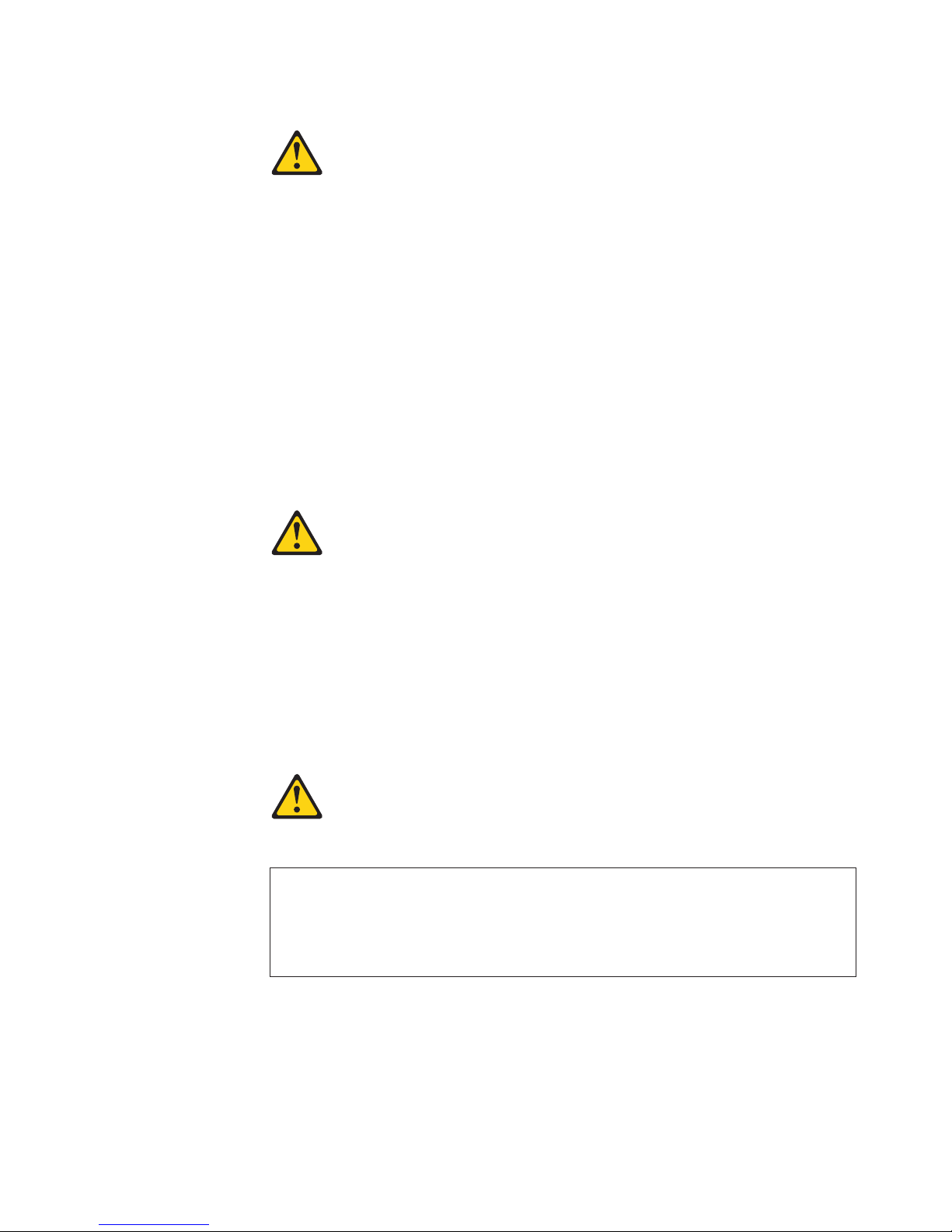
Working with adapters . . . . . . . . . . . . . . . . . . . . .34
Installing internal drives . . . . . . . . . . . . . . . . . . . . .36
Installing memory modules . . . . . . . . . . . . . . . . . . .45
Installing a security rope clip . . . . . . . . . . . . . . . . . . .47
Replacing the cover . . . . . . . . . . . . . . . . . . . . . .48
Installing options in the M Pro Type 6230 (tower model) . . . . . . . . . .50
Major components of your computer . . . . . . . . . . . . . . . .50
System-board option connectors . . . . . . . . . . . . . . . . .51
System-board internal connectors . . . . . . . . . . . . . . . . .52
System-board external connectors . . . . . . . . . . . . . . . . .53
Removing the side cover . . . . . . . . . . . . . . . . . . . .53
Removing and installing the support bracket . . . . . . . . . . . . .54
Working with adapters . . . . . . . . . . . . . . . . . . . . .55
Installing internal drives . . . . . . . . . . . . . . . . . . . . .59
Installing memory modules . . . . . . . . . . . . . . . . . . .65
Installing a security rope clip . . . . . . . . . . . . . . . . . . .67
Replacing the side cover . . . . . . . . . . . . . . . . . . . .68
Connecting external options . . . . . . . . . . . . . . . . . . . .69
Input/output connectors . . . . . . . . . . . . . . . . . . . . . .69
Audio connectors . . . . . . . . . . . . . . . . . . . . . . .70
Auxiliary-device (pointing-device) connector . . . . . . . . . . . . .71
Ethernet (RJ-45) connector . . . . . . . . . . . . . . . . . . .71
IEEE 1394 (FireWire) connector (some models) . . . . . . . . . . . .72
Keyboard connector . . . . . . . . . . . . . . . . . . . . . .72
Parallel connector . . . . . . . . . . . . . . . . . . . . . . .72
Serial connectors . . . . . . . . . . . . . . . . . . . . . . .73
Ultra320 SCSI connector . . . . . . . . . . . . . . . . . . . .73
Universal Serial Bus connectors . . . . . . . . . . . . . . . . .73
Video connector . . . . . . . . . . . . . . . . . . . . . . .74
Chapter 5. Solving problems . . . . . . . . . . . . . . . . . . .77
Diagnostic tools overview . . . . . . . . . . . . . . . . . . . . .77
Power-on self-test (POST) . . . . . . . . . . . . . . . . . . . . .79
POST beep codes . . . . . . . . . . . . . . . . . . . . . .79
POST error messages . . . . . . . . . . . . . . . . . . . . . .81
Diagnostic programs and error messages . . . . . . . . . . . . . . .85
Text messages . . . . . . . . . . . . . . . . . . . . . . . .86
Starting the diagnostic programs and viewing the test log . . . . . . . .86
Diagnostic error message tables . . . . . . . . . . . . . . . . .88
Small computer system interface (SCSI) messages . . . . . . . . . . .93
PC-Doctor for Windows . . . . . . . . . . . . . . . . . . . . . .94
Troubleshooting charts . . . . . . . . . . . . . . . . . . . . . .94
CD-ROM drive problems . . . . . . . . . . . . . . . . . . . .95
Diskette drive problems . . . . . . . . . . . . . . . . . . . . .95
Hard disk drive problems . . . . . . . . . . . . . . . . . . . .95
General problems . . . . . . . . . . . . . . . . . . . . . . .96
Intermittent problems . . . . . . . . . . . . . . . . . . . . . .96
Keyboard, mouse, or pointing-device problems . . . . . . . . . . . .96
IBM IntelliStation M Pro Types 6220 and 6230: User’s Guide
Page 7

Memory problems . . . . . . . . . . . . . . . . . . . . . . .97
Microprocessor problems . . . . . . . . . . . . . . . . . . . .97
Monitor problems . . . . . . . . . . . . . . . . . . . . . . .97
Option problems . . . . . . . . . . . . . . . . . . . . . . .98
Parallel port problems . . . . . . . . . . . . . . . . . . . . .99
Power problems . . . . . . . . . . . . . . . . . . . . . . .99
Printer problems . . . . . . . . . . . . . . . . . . . . . . .99
Serial port problems . . . . . . . . . . . . . . . . . . . . . 100
Software problems . . . . . . . . . . . . . . . . . . . . . . 100
Universal Serial Bus (USB) port problems . . . . . . . . . . . . . 100
System-board error LEDs . . . . . . . . . . . . . . . . . . . 100
Software error messages . . . . . . . . . . . . . . . . . . . . 101
Troubleshooting the Ethernet controller . . . . . . . . . . . . . . 102
Recovering your operating system and preinstalled software . . . . . . . . 102
Recovering the operating system . . . . . . . . . . . . . . . . . 102
Recovering or installing device drivers . . . . . . . . . . . . . . . 103
Creating and using an IBM Enhanced Diagnostics diskette in Windows . . . . 103
Creating an IBM Enhanced Diagnostics diskette . . . . . . . . . . . 103
Using the IBM Enhanced Diagnostics diskette . . . . . . . . . . . . 104
Using the recovery-repair diskette in Windows . . . . . . . . . . . . . 104
Updating (flash-updating) the BIOS code on your computer . . . . . . . . 105
Recovering from a POST/BIOS update failure . . . . . . . . . . . . . 105
Replacing the battery . . . . . . . . . . . . . . . . . . . . . . 106
Appendix A. Getting help and technical assistance . . . . . . . . . . 109
Before you call . . . . . . . . . . . . . . . . . . . . . . . . 109
Using the documentation . . . . . . . . . . . . . . . . . . . . . 109
Getting help and information from the World Wide Web . . . . . . . . .110
Software service and support . . . . . . . . . . . . . . . . . . .110
Hardware service and support . . . . . . . . . . . . . . . . . . .110
Appendix B. IBM Statement of Limited Warranty Z125-4753-07 11/2002
111
Part 1 - General Terms . . . . . . . . . . . . . . . . . . . . . 111
Part 2 - Country-unique Terms . . . . . . . . . . . . . . . . . . .114
Part 3 - Warranty Information . . . . . . . . . . . . . . . . . . . 125
Appendix C. Notices . . . . . . . . . . . . . . . . . . . . . . 129
Edition notice . . . . . . . . . . . . . . . . . . . . . . . . . 129
Trademarks . . . . . . . . . . . . . . . . . . . . . . . . . . 130
Important notes . . . . . . . . . . . . . . . . . . . . . . . . 130
Product recycling and disposal . . . . . . . . . . . . . . . . . . 131
Battery return program . . . . . . . . . . . . . . . . . . . . . 132
Electronic emission notices . . . . . . . . . . . . . . . . . . . . 132
Federal Communications Commission (FCC) statement . . . . . . . . 132
Industry Canada Class B emission compliance statement . . . . . . . . 133
Avis de conformité à la réglementation d’Industrie Canada . . . . . . . 133
European Union EMC Directive conformance statement . . . . . . . . 133
Japanese Voluntary Control Council for Interference (VCCI) statement
133
Power cords . . . . . . . . . . . . . . . . . . . . . . . . . 133
Index . . . . . . . . . . . . . . . . . . . . . . . . . . . . 137
Contents
v
Page 8

vi
IBM IntelliStation M Pro Types 6220 and 6230: User’s Guide
Page 9

©
Safety
Before installing this product, read the Safety Information.
Antes de instalar este produto, leia as Informações de Segurança.
Pred instalací tohoto produktu si prectete prírucku bezpecnostních instrukcí.
Læs sikkerhedsforskrifterne, før du installerer dette produkt.
Lees voordat u dit product installeert eerst de veiligheidsvoorschriften.
Ennen kuin asennat tämän tuotteen, lue turvaohjeet kohdasta Safety Information.
Avant d’installer ce produit, lisez les consignes de sécurité.
Vor der Installation dieses Produkts die Sicherheitshinweise lesen.
Prima di installare questo prodotto, leggere le Informazioni sulla Sicurezza.
Les sikkerhetsinformasjonen (Safety Information) før du installerer dette produktet.
Antes de instalar este produto, leia as Informações sobre Segurança.
Antes de instalar este producto, lea la información de seguridad.
Läs säkerhetsinformationen innan du installerar den här produkten.
Copyright IBM Corp. 2004
vii
Page 10

To
v Do
v
v
v
v
v
v
To
To
1.
2.
3.
4.
5.
1.
2.
3.
4.
Statement 1:
DANGER
Electrical
current from power, telephone, and communication cables is
hazardous.
avoid a shock hazard:
not connect or disconnect any cables or perform installation,
maintenance, or reconfiguration of this product during an electrical
storm.
Connect all power cords to a properly wired and grounded electrical
outlet.
Connect to properly wired outlets any equipment that will be attached to
this product.
When possible, use one hand only to connect or disconnect signal
cables.
Never turn on any equipment when there is evidence of fire, water, or
structural damage.
Disconnect the attached power cords, telecommunications systems,
networks, and modems before you open the device covers, unless
instructed otherwise in the installation and configuration procedures.
Connect and disconnect cables as described in the following table when
installing, moving, or opening covers on this product or attached
devices.
Connect:
Turn everything OFF.
First, attach all cables to devices.
Attach signal cables to connectors.
Attach power cords to outlet.
Turn device ON.
Disconnect:
Turn everything OFF.
First, remove power cords from outlet.
Remove signal cables from connectors.
Remove all cables from devices.
viii
IBM IntelliStation M Pro Types 6220 and 6230: User’s Guide
Page 11
a
Do
v
v
v
of
v Do
v
Statement 2:
CAUTION:
When replacing the lithium battery, use only IBM Part Number 33F8354 or an
equivalent type battery recommended by the manufacturer. If your system has
module containing a lithium battery, replace it only with the same module
type made by the same manufacturer. The battery contains lithium and can
explode if not properly used, handled, or disposed of.
not:
Throw or immerse into water
Heat to more than 100°C (212°F)
Repair or disassemble
Dispose
the battery as required by local ordinances or regulations.
Statement 3:
CAUTION:
When laser products (such as CD-ROMs, DVD drives, fiber optic devices, or
transmitters) are installed, note the following:
not remove the covers. Removing the covers of the laser product could
result in exposure to hazardous laser radiation. There are no serviceable
parts inside the device.
Use of controls or adjustments or performance of procedures other than
those specified herein might result in hazardous radiation exposure.
DANGER
Some
laser products contain an embedded Class 3A or Class 3B laser
diode. Note the following.
Laser radiation when open. Do not stare into the beam, do not view directly
with optical instruments, and avoid direct exposure to the beam.
Safety
ix
Page 12

≥ 18 kg
≥ 32 kg
≥ 55 kg
x
Statement 4:
(39.7 lb)
(70.5 lb)
(121.2 lb)
CAUTION:
Use safe practices when lifting.
Statement 5:
CAUTION:
The power control button on the device and the power switch on the power
supply do not turn off the electrical current supplied to the device. The device
also might have more than one power cord. To remove all electrical current
from the device, ensure that all power cords are disconnected from the power
source.
2
1
IBM IntelliStation M Pro Types 6220 and 6230: User’s Guide
Page 13

a
Do
No
Statement 8:
CAUTION:
Never remove the cover on a power supply or any part that has the following
label attached.
Hazardous voltage, current, and energy levels are present inside any
component that has this label attached. There are no serviceable parts inside
these components. If you suspect a problem with one of these parts, contact
service technician.
Statement 23
CAUTION:
not place any object weighing more than 50 kg (110 lb) on top of rack-mounted
devices.
>50 kg (110 lb)
Declaración 23
PRECAUCIÓN:
coloque ningún objeto que pese más de 50 kg (110 libras) encima de los
dispositivos montados en bastidor.
>50 kg (110 libras)
Safety
xi
Page 14

Ne
Hinweis 23
ACHTUNG:
Keine Gegenstände, die mehr als 50 kg wiegen, auf Rack-Einheiten ablegen.
>50 kg
Notice nø 23
ATTENTION:
posez pas d’objet dont le poids dépasse 50 kg sur les unités montées en armoire.
>50 kg
Varningsmeddelande 23
VARNING:
Placera inte något föremål som väger mer än 50 kg ovanpå rackmonterade enheter.
>50 kg
xii
IBM IntelliStation M Pro Types 6220 and 6230: User’s Guide
Page 15

in
Merknad 23
ADVARSEL:
Ikke sett gjenstander som veier mer enn 50 kg oppå enheter som er montert i et
kabinett.
>50 kg
Avviso 23
ATTENZIONE:
Non poggiare oggetti che pesano più di 50 kg sulla parte superiore delle unità montate
rack.
>50 kg
Turvaohje 23
Varoitus:
Telineeseen asennettujen laitteiden päälle ei saa asettaa yli 50 kilon painoista esinettä.
>50 kg
Safety
xiii
Page 16

Voorschrift 23
WAARSCHUWING:
Plaats geen objecten die meer dan 50 kg wegen op apparaten die in het rek zijn
gemonteerd.
>50 kg
Forskrift 23
Pas på!:
Anbring ikke genstande, der vejer mere end 50 kg, oven på enheder, der er monteret i
rack.
>50 kg
Instrução 23
CUIDADO:
Não coloque nenhum objeto com peso superior a 50 kg (110 lbs.) sobre dispositivos
montados em rack.
>50 kg (110 lbs)
xiv
IBM IntelliStation M Pro Types 6220 and 6230: User’s Guide
Page 17

50
110
23
23
50
110
50
50
Safety
xv
Page 18

23
50
23
·
50
50
> 50 Kg
50
110
110
23
50
xvi
IBM IntelliStation M Pro Types 6220 and 6230: User’s Guide
Page 19

23
110
50
50
110
23
50 110
50 110
50
23
50
Safety
xvii
Page 20

23
50 110
50
110
23
50 110
50 110
50 110
23
50
xviii
IBM IntelliStation M Pro Types 6220 and 6230: User’s Guide
Page 21

23
50 110
50 110
50 110
Instrução 23
23
50 110
Safety
xix
Page 22

xx
Instrução 23
CUIDADO:
Não coloque nenhum objeto com peso superior a 50 kg (110 lbs.) sobre dispositivos
montados em rack.
>50 kg (110 lbs)
WARNING: Handling the cord on this product or cords associated with accessories
sold with this product, will expose you to lead, a chemical known to the State of
California to cause cancer, and birth defects or other reproductive harm. Wash
hands after handling.
ADVERTENCIA: El contacto con el cable de este producto o con cables de
accesorios que se venden junto con este producto, pueden exponerle al plomo, un
elemento químico que en el estado de California de los Estados Unidos está
considerado como un causante de cancer y de defectos congénitos, además de
otros riesgos reproductivos. Lávese las manos después de usar el producto.
IBM IntelliStation M Pro Types 6220 and 6230: User’s Guide
Page 23

M
of
to
to
to
1. Go to
2. In
3. On
4. In
5.
v
v
v
v
v
©
Chapter 1. Introducing the IntelliStation M Pro computer
The IBM
®
IntelliStation
®
Pro Types 6220 and 6230 incorporate many of the latest
advances in computing technology and can be expanded and upgraded as your
needs change.
You can obtain up-to-date information about your computer and other IBM computer
products at http://www.ibm.com/pc/intellistation/ .
The computer model and serial numbers for Type 6220 are on labels on the bottom
the computer and on the lower-left side of the bezel. The computer model and
serial numbers for Type 6230 are on labels on the bottom of the computer and on
the lower-right side of the bezel. You will need these numbers to register your
computer with IBM.
Note: The illustrations in this document might differ slightly from your hardware.
Your computer might have features that are not described in the documentation that
you received with the computer. The documentation might be updated occasionally
include information about those features, or technical updates might be available
provide additional information that is not included in your system documentation.
These updates are available from the IBM Web site. Complete the following steps
check for updated documentation and technical updates:
http://www.ibm.com/pc/support/.
the Learn section, click Online publications.
the “Online publications” page, in the Brand field, select IntelliStation.
the Family field, select IntelliStation M Pro.
Click Display documents.
Related publications
This User’s Guide provides general information about your computer, including
information about features, how to configure your computer, how to install options,
and how to solve problems and get help. In addition to this User’s Guide, the
following documentation comes with your computer.
Installation Guide
This printed publication contains setup and installation instructions.
Safety Information
This publication is in Portable Document Format (PDF) on the IBM IntelliStation
Documentation CD. It contains translated caution and danger statements. Each
caution and danger statement that appears in the documentation has a number
that you can use to locate the corresponding statement in your language in the
Safety Information book.
Adaptec SCSI documentation
This publication is in PDF on the Device Drivers CD. It contains information and
instructions for installing and configuring small computer system interface (SCSI)
device drivers and devices.
Readme files on the Device Drivers CD
Several readme files on this CD contain information about the preinstalled device
drivers. Other readme files on this CD contain information about the various
adapters and devices that might be installed in or attached to your computer.
Hardware Maintenance Manual
Copyright IBM Corp. 2004
1
Page 24

v
v
v
v
v
to
v
2
This publication is in PDF at http://www.ibm.com/pc/support/. It contains
information for trained service technicians.
IBM IntelliStation Documentation CD
This CD contains all of the IBM IntelliStation M Pro Types 6220 and 6230
publications in Portable Document Format (PDF).
Notices and statements used in this book
The caution and danger statements that appear in this book are also in the
multilingual Safety Information book, which is on the IBM IntelliStation
Documentation CD. Each statement is numbered for reference to the corresponding
statement in the Safety Information book.
The following notices and statements are used in this book:
Notes: These notices provide important tips, guidance, or advice.
Important: These notices provide information or advice that might help you avoid
inconvenient or problem situations.
Attention: These notices indicate potential damage to programs, devices, or
data. An attention notice is placed just before the instruction or situation in which
damage could occur.
Caution: These statements indicate situations that can be potentially hazardous
you. A caution statement is placed just before the description of a potentially
hazardous procedure step or situation.
Danger: These statements indicate situations that can be potentially lethal or
extremely hazardous to you. A danger statement is placed just before the
description of a potentially lethal or extremely hazardous procedure step or
situation.
IBM IntelliStation M Pro Types 6220 and 6230: User’s Guide
Page 25

v
4
v
v
v
v
v
v
v
v
–
–
–
v
v
v
v
v
v
v
v
v
v
v
v
v
–
–
–
v
v
v
v
v
–
–
–
–
–
–
v
v
v
–
–
v
v
v
v
v
v
or
Features and specifications — M Pro Type 6220 (desktop model)
The following information is a summary of the features and specifications of your
IntelliStation M Pro Type 6220 desktop computer. Depending on your model, some
features might not be available, or some specifications might not apply.
Table 1. Features and specifications
Microprocessor:
Intel
™
Pentium
®
processor
512 KB Level-2 cache
800 MHz front-side bus (FSB)
Memory:
Minimum: 256 MB
Maximum: 4 GB
Type: PC2700 or PC3200
Connectors: four dual inline memory
module (DIMM) connectors
Internal
Drives:
Hard disk drive: IDE or SATA
One of the following drives:
CD-ROM: IDE
DVD/CD-RW combo: IDE
CD-RW: IDE
Expansion
bays:
Two slim-high 3.5-inch drive bays
(one hard disk drive installed in some
models)
One half-high 5.25-inch bay (optical
drive installed in one bay)
expansion slots:
PCI
Three 33 MHz/32-bit PCI slots on the
system board
One Accelerated Graphic Port (AGP)
slot
supply:
Power
One 200 watts (90-240 V ac)
Cooling:
One or two speed-controlled fans
Integrated functions:
Intel Ethernet controller on the system
board with RJ-45 Ethernet connector
Two serial ports
One parallel port
(Some models) two IEEE 1394
(FireWire) ports (four-pin on front,
six-pin on rear)
Dual port serial ATA controller
Six Universal Serial Bus (USB) ports
(two on front and four on rear)
Keyboard port
Mouse port
Audio ports
Line out (front and rear)
Mic (front and rear)
Line in (rear)
Dual-channel IDE controller
v
adapter: (depending on your
Video
model)
NVIDIA Quadro NVS 280 (LFH-60),
AGP 8X, with 64 MB double-data-rate
(DDR) synchronous dynamic random
access memory (SDRAM) video
memory and dual analog connectors (or
dual digital monitor capability with the
purchase of an additional pigtail cable)
NVIDIA Quadro4 580XGL (LFH-60),
AGP 8X, with 64 MB DDR SDRAM
video memory and dual analog
connectors (or dual digital monitor
capability with the purchase of an
additional pigtail cable)
Electrical input:
Sine-wave input (50 or 60 Hz) required
Input voltage and frequency ranges switch
selected
Input voltage low range:
Minimum: 90 V ac
Maximum: 137 V ac
v
Input voltage high range:
Minimum: 180 V ac
Maximum: 265 V ac
v
Input kilovolt-amperes (kVA) approximately:
Minimum: 0.13 kVA
Maximum: 0.32 kVA
output:
Heat
Approximate heat output in British thermal
units (Btu) per hour
Minimum configuration: 421 Btu (124 watts)
Maximum configuration: 1050 Btu (308
watts)
Environment:
Air temperature:
Computer on: 10° to 35°C (50° to 95°F)
Altitude: 0 to 2134 m (7000 ft)
Computer off: -40° to +60°C (-40° to
+140°F)
Maximum altitude: 2133 m (7000 ft)
v
Humidity (operating and storage): 8% to
80%
Acoustical
noise emissions:
Sound power, idle: 4.8 bel
Sound power, operating: 4.9 bel
Size:
Height: 104 mm (4.1 in.)
Depth: 412 mm (16.2 in.)
Width: 360 mm (14.2 in.)
Weight: 9.1 kg (20 lb) when fully configured
6.8 kg (15 lb) minimum
Chapter 1. Introducing the IntelliStation M Pro computer
3
Page 26

v
v
v
v
v
v
v
v
v
v
–
–
–
v
v
v
v
v
v
v
v
v
v
v
v
v
v
–
–
–
v
v
v
v
v
v
v
v
v
v
–
–
–
–
–
–
v
v
v
–
–
v
v
v
v
v
v
4
Features and specifications — M Pro Type 6230 (tower model)
The following information is a summary of the features and specifications of your
IntelliStation M Pro Type 6230 tower computer. Depending on your model, some
features might not be available, or some specifications might not apply.
Table 2. Features and specifications
Microprocessor:
Intel Pentium 4 processor
512 KB Level-2 cache
800 MHz front-side bus (FSB)
Memory:
Minimum: 256 MB
Maximum: 4 GB
Type: PC2700 or PC3200
Connectors: four dual inline memory
module (DIMM) connectors
Internal
Drives:
Diskette: 1.44 MB (two mode)
Hard disk drive: IDE, SATA , or SCSI
One of the following drives:
CD-ROM: IDE
DVD/CD-RW combo: IDE
CD-RW: IDE
Expansion
bays:
Three slim-high 3.5-inch drive bays
(one hard disk drive installed in some
models)
Two half-high 5.25-inch bays (optical
drive installed in one bay)
Two slim-high 3.5-inch
removable-media drive bays (one
diskette drive installed)
expansion slots:
PCI
Five 33 MHz/32-bit PCI slots on the
system board
One Accelerated Graphic Port (AGP)
Pro 110 slot
supply:
Power
One 340 watts (115-230 V ac)
Cooling:
Two speed-controlled fans
Integrated functions:
Intel Ethernet controller on the system
board with RJ-45 Ethernet connector
Two serial ports
One parallel port
(Some models) two IEEE 1394
(FireWire) ports (four-pin on front,
six-pin on rear)
Dual port serial ATA controller
Six Universal Serial Bus (USB) ports
(two on front and four on rear)
Keyboard port
Mouse port
Audio ports
Line out (front and rear)
Mic (front and rear)
Line in (front and rear)
Dual-channel IDE controller
v
adapter: (depending on your
Video
model)
NVIDIA Quadro NVS 280 (LFH-60),
AGP 8X, with 64 MB double-data-rate
(DDR) synchronous dynamic random
access memory (SDRAM) video
memory and dual analog connectors (or
dual digital monitor capability with the
purchase of an additional pigtail cable)
NVIDIA Quadro4 580XGL (LFH-60),
AGP 8X, with 64 MB DDR SDRAM
video memory and dual analog
connectors (or dual digital monitor
capability with the purchase of an
additional pigtail cable)
NVIDIA Quadro FX 500 (DVI-I & VGA),
AGP 8X, with 128 MB DDR SDRAM
video memory with one DVI-I connector
and one analog VGA connector
NVIDIA Quadro4 980XGL (DVI-I), AGP
8X, with 128 MB DDR synchronous
graphics random access memory
(SGRAM) video memory with dual DVI-I
connectors
NVIDIA Quadro FX 1000 (DVI-I), AGP
8X, with 128 MB DDR2 SDRAM video
memory with dual DVI-I connectors
NVIDIA Quadro FX 1100 (DVI-I), AGP
8X, with 128 MB DDR SDRAM video
memory with dual DVI-I connectors
NVIDIA Quadro FX 3000 (DVI-I), AGP
8X, with 256 MB DDR SDRAM video
memory with dual DVI-I connectors
Electrical input:
Sine-wave input (50 or 60 Hz) required
Input voltage and frequency ranges
automatically selected
Input voltage low range:
Minimum: 90 V ac
Maximum: 137 V ac
v
Input voltage high range:
Minimum: 180 V ac
Maximum: 265 V ac
v
Input kilovolt-amperes (kVA) approximately:
Minimum: 0.13 kVA
Maximum: 0.55 kVA
output:
Heat
Approximate heat output in British thermal
units (Btu) per hour
Minimum configuration: 421 Btu (124 watts)
Maximum configuration: 1782 Btu (523
watts)
Environment:
Air temperature:
Computer on: 10° to 35°C (50° to 95°F)
Altitude: 0 to 2134 m (7000 ft)
Computer off: -40° to +60°C (-40° to
+140°F)
Maximum altitude: 2133 m (7000 ft)
v
Humidity (operating and storage): 8% to
80%
Acoustical
noise emissions:
Sound power, idle: 4.9 bel
Sound power, operating: 5.0 bel
Size:
Height: 438 mm (17.25 in.)
Depth: 483 mm (19 in.)
Width: 265 mm (6.5 in.)
Weight: 16.3 kg (36 lb) to 20.8 kg (45.8 lb)
depending upon configuration
IBM IntelliStation M Pro Types 6220 and 6230: User’s Guide
Page 27

v
v
v
v
XP
or
What your computer offers
Your computer takes advantage of advancements in data storage, memory, systems
management, and network environments. Your computer includes:
Accelerated Graphics Port (AGP) graphics
Your computer comes with an installed AGP graphics adapter. This
high-performance adapter supports high resolutions and includes many
performance-enhancing features for your operating-system environment.
Large system-memory capacity
Your computer supports up to 4.0 GB of system memory. The memory controller
provides error correcting code (ECC) support for up to four industry-standard
PC2700 or PC3200, 2.5 V, 184-pin, unbuffered, double-data-rate synchronous
dynamic random access memory (DDR SDRAM) dual inline memory modules
(DIMMs).
Systems-management capabilities
Your computer comes with features that a network administrator or file server can
use to remotely manage and control your computer. Some of the features include
Wake on LAN®, Remote Administration, IBM Director Agent, and System
Migration Assistant. See “Managing your computer” on page 19 for more
information.
Integrated network support
Your computer comes with an integrated Ethernet controller, which supports
connection to a 10-Mbps, 100-Mbps, or 1-Gbps network. The computer
automatically selects between 10BASE-T, 100BASE-TX, and Gigabit
environments. The controller provides full-duplex (FDX) capability, which enables
simultaneous transmission and reception of data on the Ethernet local area
network (LAN). The controller supports Wake on LAN technology.
Software
1. The Microsoft
Microsoft Corporation.
®
Your IBM IntelliStation M Pro computer comes with Microsoft Windows
Professional, Windows 2000 Professional Workstation,
1
Red Hat Enterprise Linux
®
Workstation preinstalled and a variety of software, including application programs,
diagnostic tools, and device drivers.
Important: The software, other than the operating system, is licensed under the
terms of the IBM International License Agreement for Non-Warranted
Programs. Use of your computer signifies acceptance of this license
agreement. For detailed instructions about viewing the license
agreement, see “Viewing the license agreement” on page 13.
Certificate of Authenticity is your assurance that the Windows software in your computer is legally licensed from
Chapter 1. Introducing the IntelliStation M Pro computer
5
Page 28

In
of
v
v
v
v
v
v
v
v
v
v
v
6
Preinstalled software
addition to the operating system, your preinstalled software includes some or all
the following programs. Some programs might require setup and configuration
before use:
Access IBM Message Center
This program displays messages about software that is preinstalled on your
computer. Access IBM Message Center also provides messages about new
updates available from the IBM Support Center to keep your software current.
Adobe Acrobat Reader
You can use this program to read files in Portable Document Format (PDF),
including your online documentation. You can download the most current
versions of Adobe Acrobat Reader for other languages and operating systems
from the Adobe Web site at http://www.adobe.com.
Device Drivers
Device drivers for factory-installed features are preinstalled on your computer.
The latest device drivers are also available at http://www.ibm.com/pc/support/.
IBM Access Support
You can use this program to find tools, support, and services to help diagnose
and solve common hardware and software application problems. IBM Access
Support provides information and functions, including automated self-service,
assisted service, and links to other tools and sources of information.
IBM Drive Letter Access
You can use this program to copy files to CD-R or CD-RW media.
IBM Product Registration
You can use this program to register your computer with IBM. When you register
your computer with IBM, information is entered into a database, which enables
IBM to contact you in case of a recall or other problems. Some IBM locations
offer extended privileges and services to registered users.
IBM RecordNow
You can use this program to record data or audio to CD-R or CD-RW media or to
create copies of existing CDs.
Norton AntiVirus for IBM
You can use this program to detect and remove viruses from your computer.
Online Books
You can use this program to access documentation that contains detailed
information about your computer.
PC-Doctor for Windows
This program contains diagnostic tools that you can use within your operating
system. In addition to isolating hardware problems, these tools provide
information about your computer operating environment and some software
components. Support documentation is built into the help system. (See also
“Creating an IBM Enhanced Diagnostics diskette” on page 103.)
Product Recovery Program
You can use this program to recover the operating system and other software
programs in the event of a system failure.
Important: The Product Recovery Program is on a hidden, hard disk drive
IBM IntelliStation M Pro Types 6220 and 6230: User’s Guide
partition. Do not delete or otherwise destroy this partition.
Page 29

1.
2.
In
is
CD
1. Go to
2.
3.
4.
5.
Software on CD
You must have Internet access to use some of these programs. For more
information about connecting to the Internet, see the operating-system
documentation that comes with your computer.
See “Using preinstalled software” on page 12 for additional information about your
preinstalled software. For more information about using the recovery programs and
solving problems, see Chapter 5, “Solving problems,” on page 77.
Important:
You can reinstall the device drivers and applications that come with your
computer from the directories on your hard disk. For more information about
recovering your computer software, see “Recovering your operating system and
preinstalled software” on page 102.
The device drivers and some programs are also available at
http://www.ibm/com/pc/support/ and on the Device Drivers CD.
addition to your IBM-preinstalled programs and device drivers, additional software
provided on the Device Drivers CD or other CDs. You decide which programs to
install based on your needs.
Device drivers
Some of the preinstalled device drivers are on the Device Drivers CD that
comes with your computer.
Lotus
®
SmartSuite
®
The Lotus SmartSuite package contains powerful, award-winning
productivity applications and everything you need to access the Internet.
Your computer comes with either a Lotus SmartSuite CD or a proof of
entitlement to receive one free CD version of the Lotus SmartSuite
package. To install your SmartSuite package, insert the Lotus SmartSuite
into the CD-ROM drive, or contact your network administrator for
assistance.
Software available on the World Wide Web
This section describes some of the software that is available from the IBM Web
site. See to the product documentation for these tools to find out whether your
operating system supports this software. Complete the following steps to get more
detailed information about these tools or to download any of this software:
http://www.ibm.com/pc/support/ and select your country.
Click the Products and services tab at the top of the page.
Under Servers, click Intel processor-based.
From the topics on the left, click Systems Management.
Scroll down and click on a product to get more details about the product. To
download a product, select Systems Management Downloads from the
Deployment and update management category.
following software is available from the IBM Web site:
The
IBM Director Agent
You can use IBM Director Agent to view detailed information about your
hardware and software, set up alerts, monitor a variety of system
resources, and manage your asset security. IBM Director Agent streamlines
and automates personal computer (PC) systems management and support
tasks, such as asset deployment and tracking.
Chapter 1. Introducing the IntelliStation M Pro computer
7
Page 30

of
is
v 24
v
v
v
v
v
v
v
v
v
v
v
v
v
v
v
v
v
v
v
v
8
Remote Deployment Manager
Remote Deployment Manager (RDM) is a graphical, server-based system
deployment program that enables mass unattended installations of
operating systems, software images, device drivers, and BIOS code
updates to remote systems. When used with the Wake on LAN feature,
Remote Deployment Manager can remotely turn on your computer so that
the installation can be done while the computer is not being used.
System Migration Assistant
System administrators can use System Migration Assistant (SMA) to
remotely transfer configurations, profile settings, printer device drivers, and
files from an IBM or non-IBM computer to supported IBM systems.
Software Delivery Assistant
You can use Software Delivery Assistant to create an image of a single set
applications that can be deployed to different user groups while taking
into account the users’ application needs.
Reliability, availability, and serviceability features
Three important computer design features are reliability, availability, and
serviceability (RAS). The RAS features help to ensure the integrity of the data that
stored in your computer, the availability of the computer when you need it, and
the ease with which you can diagnose and repair problems.
Your computer has the following RAS features:
hours a day, 7 days a week
2
customer support
3-year limited warranty
Advanced Configuration and Power Interface (ACPI)
Auto-restart initial program load (IPL) power supply
Automatic computer restart after a power failure
Automatic error retry or recovery
Boot-block recovery
Built-in, menu-driven configuration and setup programs
Built-in, menu-driven SCSI configuration programs (some models)
Cooling fans with speed-sensing capability
Error codes and messages
Error correcting code (ECC) double-data-rate (DDR) synchronous dynamic
random access memory (SDRAM) with serial presence detect (SPD)
Hard drive partition-based diagnostic programs
Integrated Ethernet controller
Monitoring support for temperatures, voltages, and fan speed
Power-on self-test (POST)
Predictive Failure Analysis
®
(PFA) on hard disk drives
Processor serial number access
Read-only memory (ROM) checksums
Upgradeable basic input/output system (BIOS) and POST code
Wake on LAN capability
2. Service availability will vary by country. Response time varies; may exclude holidays.
IBM IntelliStation M Pro Types 6220 and 6230: User’s Guide
Page 31

©
Chapter 2. Operating the computer
This chapter provides information about how to use your computer.
Controls and LEDs
The following illustration shows the controls and indicators on the M Pro Type 6220
desktop computer.
Ethernet transmit/
receive activity
Ethernet link status LED
CD-ROM drive
activity LED
CD eject
button
Power-control
button
Power-on LED
Hard disk drive
activity LED
IEEE 1394 (FireWire)
connector
Microphone connector
Line out connector
USB ports
Copyright IBM Corp. 2004
9
Page 32

10
The following illustration shows the controls and indicators on the M Pro Type 6230
tower computer.
Ethernet link status LED
CD-ROM drive
activity LED
CD-eject
button
Diskette drive
activity LED
Diskette-eject
button
Hard disk drive
activity LED
Ethernet
transmit/receive
activity LED
CD-ROM drive activity LED
When this LED is lit, it indicates that the CD-ROM drive is in use.
CD-eject button
Press this button to insert a CD into or remove a CD from the CD-ROM
drive.
Diskette drive activity LED
When this LED is lit, it indicates that the diskette drive is in use.
Diskette-eject button
Press this button to release a diskette from the diskette drive.
Hard disk drive activity LED
When this LED is lit, it indicates that the hard disk drive is in use.
Power-on
1394
LED
Power-control
button
Ethernet transmit/
receive activity LED
System error LED
IEEE 1394 (FireWire) connector
1394
Microphone connector
Line out connector
USB port connector
USB port connector
Power-on LED
When this LED is lit and not flashing, it indicates that the computer is
turned on. When this LED is flashing, it indicates that the computer is off
and still connected to an ac power source (standby mode).
Power-control button
Press this button to turn the computer on or off.
Ethernet transmit/receive activity LED
When this LED is lit, it indicates that there is activity between the computer
and the network. There are two of these LEDs, one on the front and one on
the rear of the computer.
Ethernet link status LED
When this LED is lit, it indicates that there is an active connection on the
Ethernet port. This LED is located on the rear of the computer.
IBM IntelliStation M Pro Types 6220 and 6230: User’s Guide
Page 33

An
1.
2.
be
v If a
v
If
no
System-error LED
When this amber LED is lit, it indicates that a system error has occurred.
LED on the system board is also lit to help isolate the error.
IEEE 1394 (FireWire) connectors
Use these connectors (four-pin on the front and six-pin on the rear) to
connect FireWire devices, such as digital video cameras and external hard
disk drives.
Note: Some models come with the IEEE 1394 FireWire adapter installed. If
your computer did not come with this adapter installed, do not install
any adapter in the mini-PCI slot. It is not supported.
connector (pink)
Mic
Use this connector to connect a microphone to your computer when you
want to record voices or other sounds on the hard disk. You can also use
this connector (and a microphone) with speech recognition software.
Line out connector (green)
Use this connector to send audio signals from the computer to external
devices, such as speakers with built-in amplifiers, headphones, multimedia
keyboards, or the audio line-in jack on a stereo system.
USB ports
Use these connectors to connect USB devices to your computer, using
redundant Plug and Play technology.
Turning on the computer
When the computer is connected to an ac power source but is not turned on, the
operating system does not run, and all core logic is shut down; however, the
computer can respond to remote requests to turn on the computer. The power-on
LED flashes to indicate that the computer is connected to an ac power source but is
not turned on (standby mode).
Notes:
Turn on all external devices, such as the monitor, before turning on the
computer.
The power-on LED on the front of the computer is lit when the computer is on
and while it is being turned on.
Approximately 20 seconds after the computer is connected to ac power, the
power-control button becomes active, and you can turn on the computer and start
the operating system by pressing the power-control button. The computer can also
turned on in any of the following ways:
power failure occurs while the computer is turned on, the computer will
restart automatically when power is restored.
When you connect your computer to power for the first time, the Wake on LAN
feature can turn on the computer. If your computer was previously turned on, it
must be turned off for the Wake on LAN feature to turn on the computer.
What you see and hear when you start your computer depends on the features
installed and the settings in the Configuration/Setup Utility program.
power-on self-test (POST) detects a problem, there might be a series of beeps or
beep, and a numeric error message might appear on the screen. Write down
Chapter 2. Operating the computer
11
Page 34

v To
v
v
v
v
To
To
If
is
1.
12
any beep series and error code numbers with descriptions, and then see
“Troubleshooting charts” on page 94 for an explanation of the error codes.
During startup on the Windows operating system, the following messages might be
displayed briefly:
start the Product Recovery Program, Press F11
Press F1 for Configuration/Setup Utility, Press F12 for Boot Menu
Press CTRL+A for SCSISelect Utility (some models)
During
startup on the Red Hat Linux operating system, the following messages
might be displayed briefly:
Press F1 for Configuration/Setup Utility
Press CTRL+A for SCSISelect Utility (some models)
Note:
start the Product Recovery Program in Red Hat Linux, watch the screen
until the operating system selection menu is displayed and select IBM
Preload Recovery & Diagnostics.
use these features, press the applicable function key or keys quickly. The
messages appear for only a short time. For more information about these
messages, see “Using the Configuration/Setup Utility program” on page 23 and
“Using the SCSISelect Utility program (some models)” on page 26.
During startup, you might not see the message Press F1 for Configuration/Setup.
you want to see the prompt, see the instructions for displaying the prompt in
“Using the Configuration/Setup Utility program” on page 23.
Use the Configuration/Setup Utility program to configure your computer with
passwords, PCI adapters, and other options. The Configuration/Setup Utility menu
displayed at the top of the screen. To navigate the menu and screen items, follow
the instructions on the screen.
The operating system and application programs start from the hard disk drive. If
your computer is attached to a network, the computer will begin attaching to any
LANs and remote applications to which you have access. A network administrator
can also start your computer remotely to download programs or gather information
about computer performance. For more information, see “Wake on LAN” on page
19.
Using preinstalled software
This section contains information to assist you in setting up the preinstalled
operating system and describes how to use the programs that come with your
computer.
Running the operating-system setup program
The setup program runs automatically when you start the computer. The program
will prompt you to make choices or type information. If you need more detailed
information than is provided in this User’s Guide, see your operating-system
manual.
Important:
After turning on your computer for the first time, you must complete the
operating-system setup procedure before turning off your computer; otherwise,
unexpected results might occur.
IBM IntelliStation M Pro Types 6220 and 6230: User’s Guide
Page 35

3.
4.
v
v
v
If
1.
2.
1.
2.
2.
The setup program might be slightly different from the one described in your
operating-system manual. Some choices do not appear because they are
preset.
During the setup procedure, you must indicate that you accept the license
agreement.
For Windows operating systems, the registration information will already be
displayed in the registration field. If the Product ID number is not already
displayed, you must type it. The Product ID is on a label attached to the
computer.
You will need the following information to complete the setup program:
The documentation that comes with your computer.
Network information from your network administrator, if your computer is being
connected to a network.
The printer model and port, if a printer is attached directly to your computer.
After the setup procedure is completed and the computer restarts, the desktop
opens. Your computer is ready for use.
Installing other operating systems
Your computer comes with Microsoft Windows XP Professional, Windows 2000
Professional Workstation, or Red Hat Enterprise Linux Workstation preinstalled. To
install another operating system, follow the instructions in the documentation that
comes with the operating system.
you are installing an operating system other than Microsoft Windows or Red Hat
Linux, follow the instructions in the readme files on the Device Drivers CD to install
the device drivers. If you install other than a Microsoft Windows or Red Hat Linux
operating system, you might need additional software or device drivers.
Note: If you experience problems with the device drivers installed from the Device
Drivers CD, you can obtain the latest device drivers at
http://www.ibm.com/pc/support/.
Before installing any operating system, be sure you obtain the latest updates.
Contact the operating-system manufacturer or, if applicable, check the
manufacturer’s Web site to obtain the updates.
Additional information about operating systems is posted periodically at
http://www.ibm.com/pc/support/.
Viewing the license agreement
The IBM International License Agreement for Non-Warranted Programs is viewable
from the Access IBM folder. Use of your computer signifies acceptance of this
agreement.
Complete the following steps to view the license agreement in Windows XP:
From the Windows XP desktop, click Start → All Programs → Access IBM.
Click IBM License Agreement.
Complete the following steps to view the license agreement in Windows 2000:
From the Windows 2000 desktop, click Start → Programs → Access IBM.
Click IBM License Agreement.
Chapter 2. Operating the computer
13
Page 36

v
→
v
At
v
v
1.
2.
3.
4.
1.
2.
3.
14
For Red Hat Linux, when you start your computer, the License Agreement window
opens. To accept the terms of the agreement, click I Agree. You can also view the
license agreement by clicking on the IBM License Agreement icon on your
desktop.
Registering your computer
Registering your computer helps IBM provide better service to you. When IBM
receives your registration information, the information is placed into a central
technical support database. If you need technical assistance, the technical-support
representative will have information about your computer. In addition, comments
about your computer are reviewed by a team dedicated to customer satisfaction
and are taken into consideration in making improvements to IBM computers.
Use one of the following methods to register your computer in Windows:
From the Windows XP desktop, click Start → All Programs → IBM Registration
and then follow the instructions. From the Windows 2000 desktop, click Start →
Programs
have access to the Internet, you can use the registration program that starts
through the IBM Registration folder to print your registration information and
provide IBM with a mailing address for future technical asistance.
Register your computer at http://www.ibm.com/pc/register/.
IBM Registration and then follow the instructions. If you do not
For Red Hat Linux, click the Register PC icon on the desktop to register your
computer on the World Wide Web.
Creating an emergency recovery-repair diskette in Windows
your earliest opportunity, create a recovery-repair diskette and an IBM Enhanced
Diagnostics diskette, and store them in a safe place. In the unlikely event that your
computer becomes unusable, you can use the recovery-repair diskette to access
the Product Recovery program. For more information about using this diskette, see
“Using the recovery-repair diskette in Windows” on page 104.
You can use one of the following methods to create a recovery-repair diskette in
Windows:
Create a diskette from the c:\ibmtools directory
Create a diskette from the Product Recovery program partition
Complete
c:\ibmtools directory:
Complete the following steps to create a recovery-repair diskette from the Product
Recovery program partition:
the following steps to create a recovery-repair diskette from the
Start your computer and operating system.
Use Windows Explorer to display the directory structure of your hard disk.
Open the c:\ibmtools folder.
Double-click rrdisk.bat and follow the instructions on the screen.
Shut down the operating system and turn off the computer.
Wait for at least 5 seconds; then, press and hold the F11 key while you restart
the computer. When a menu appears, release the F11 key.
Use one of the following procedures:
IBM IntelliStation M Pro Types 6220 and 6230: User’s Guide
Page 37

If a
v If an
5.
6.
to
to
1.
2.
3.
4.
5.
1. Go to
2.
3.
4. In
5.
6. On
7. At a
8.
9.
is
is
v
menu is displayed that gives you the opportunity to select an operating
system, use the arrow keys to select the operating system that is currently
installed, press Enter, and then continue with the next step.
operating system menu is not displayed, continue with the next step.
From the Product Recovery Main menu, use the arrow keys to select System
4.
utilities, and then press Enter.
Use the arrow keys to select Create a Recovery Repair diskette, and then
press Enter.
Follow the instructions on the screen.
“Creating an IBM Enhanced Diagnostics diskette in Windows” for information
See
about how to create an IBM Enhanced Diagnostics diskette.
Creating an IBM Enhanced Diagnostics diskette in Windows
The IBM Enhanced Diagnostics diskette is a self-starting diagnostics diskette used
test hardware components on your computer. Use one of the following methods
create an IBM Enhanced Diagnostics diskette.
Complete the following steps to create a startable IBM Enhanced Diagnostics
diskette from the Product Recovery program on the hard drive partition:
Restart your computer and watch the monitor.
When the message, To start the Product Recovery Program, Press F11
appears, quickly Press F11.
Select System utilities.
Next, select Create IBM Enhanced Diagnostics Diskette.
Follow the instructions on the screen.
Complete
the following steps to create a startable IBM Enhanced Diagnostics
diskette from the World Wide Web:
http://www.ibm.com.
Click Support & downloads.
Click Search technical support.
the Enter keyword(s) field, type diagnostics 6220 or 6230, and click
Submit.
From the “Search results” page, click the Enhanced Diagnostics item for your
computer.
the next page, click the executable file for the Enhanced Diagnostics code to
download it (be sure to download the file to a hard disk directory and not to a
diskette). You can click the text file to display the readme file.
command prompt, change to the directory where the file was downloaded.
Insert a blank, high-density diskette into the diskette drive.
Type filename x: where filename is the name of the file you downloaded and x
the letter for the diskette drive; then, press Enter.
downloaded file is self-extracting and is copied to the diskette. When the copy
The
completed, store the diskette in a safe place.
For more information, see “Using the IBM Enhanced Diagnostics diskette” on page
104.
Chapter 2. Operating the computer
15
Page 38

To
To
If
If
If
16
Using video features
Your computer has an Accelerated Graphics Port (AGP) graphics adapter that
renders 2D or 3D image quality and uses a standard video protocol for displaying
text and graphic images on a monitor screen. The adapter supports a variety of
video modes. Video modes are different combinations of resolution, refresh rate,
and color defined by a video standard for displaying text or graphics.
Video device drivers
take full advantage of the graphics adapter in your computer, some operating
systems and application programs require custom video device drivers. These
device drivers provide greater speed, higher resolution, more available colors, and
flicker-free images.
Device drivers for the graphics adapter and a readme file with instructions for
installing the device drivers are provided on the Device Drivers CD that comes with
your computer and in the c:\ibmtools\drivers directory on the hard disk. Use the
device-driver installation instructions if you need to reinstall the device drivers or if
you need information about obtaining and installing updated device drivers. For
more information about installing device drivers, see “Recovering or installing device
drivers” on page 103.
Changing monitor settings
get the best possible image on your screen and to reduce flicker, you might
need to reset the resolution and refresh rate of your monitor. You can view and
change monitor settings through your operating system using the instructions in the
readme files on the Device Drivers CD or in the c:\ibmtools\drivers\ directory on the
hard disk. See your operating-system documentation for more information about
monitor settings.
Attention: Before changing monitor settings, review the documentation that
comes with your monitor. Using a resolution or refresh rate that is not supported by
your monitor might cause the screen to become unreadable and could damage the
monitor. The information that comes with your monitor usually includes resolution
and screen refresh rates that your monitor supports. If you need additional
information, contact the manufacturer of the monitor.
you are using a cathode ray tube (CRT) monitor, set your monitor for the highest
noninterlaced refresh rate that the monitor supports. If your monitor complies with
the Video Electronics Standards Association (VESA) display data channel (DDC)
standard, it is probably already set to the highest refresh rate the monitor and video
controller can support. If you are not sure whether your monitor is DDC-compliant,
see the documentation that comes with the monitor.
you are using a flat-panel monitor, the refresh rate does not have to be set to the
highest noninterlaced refresh rate that the monitor supports. Flat-panel monitors
produce flicker-free images even when they are operating at a minimum 60 Hz
noninterlaced rate.
you have a dual-monitor video adapter, see the video adapter device-driver
readme file and documentation for more information about enabling dual monitors.
IBM IntelliStation M Pro Types 6220 and 6230: User’s Guide
Page 39

To
A
in a
Using audio features
Your computer has an integrated audio controller that supports Sound Blaster
applications. Your computer also has a single internal speaker and three types of
audio connectors. Using the audio controller, you can record and play back sound
and music to enhance multimedia applications. Optionally, you can connect external
speakers to the line-out connector to provide improved sound with multimedia
applications.
The audio connectors in your computer are 3.5 mm (0.125-in.) mini-jacks. For the
location of the audio connectors, see “Input/output connectors” on page 69.
Line in
Line out
This connector accepts audio signals into the computer sound system from
external devices, such as the line output from a stereo, television, or a
musical instrument. One line-in connector is on the rear of the computer.
This connector sends audio signals from the computer to external devices,
such as speakers with built-in amplifiers, headphones, multimedia
keyboards, or the audio line-in jack on a stereo system. Line-out connectors
are on both the front and the rear of the computer.
Microphone
This connector is used to connect a microphone to your computer when
you want to record voice or other sounds on the hard disk. With a
microphone attached to the computer, you can also use speech recognition
software. Microphone connectors are on both the front and the rear of the
computer.
Using security features
deter unauthorized use of your computer, you can use anti-intrusion features and
other security features that are provided with your computer.
Anti-intrusion features
IBM anti-intrusion features help protect against the theft of computer components,
such as the microprocessor, system memory modules, or hard disk drives.
cover lock is built into your computer to prevent the cover from being removed.
Two identical keys for the cover lock are also supplied. A tag attached to the keys
has the key serial number and the address of the key manufacturer.
Important: Keep the key-code number, manufacturer address, and phone number
safe place. Because locksmiths are not authorized to duplicate
cover-lock keys, you must order replacement keys from the key
manufacturer. You will need the key code when ordering replacement
keys.
You can set the chassis-intrusion detector switch inside the computer to alert the
network administrator each time the computer cover is removed. For more
information about setting the chassis-intrusion alert, see Chapter 3, “Configuring the
computer,” on page 23.
Chapter 2. Operating the computer
17
Page 40

v
be
v
of
18
Component protection
Each component in your computer has a serial number that you can register with a
security company. You can register the components individually, or you can register
the entire computer. By registering computer components, you can improve the
chances of identifying the components if they are ever stolen and recovered. For
more information about component registration, go to
http://www.ibm.com/pc/support/.
Data protection
You can lose data from the hard disk for a variety of reasons. Security violations,
viruses, or hard disk drive failures can all contribute to data loss. To help protect
against the loss of valuable information, IBM has incorporated the following
data-saving features in your computer.
SMART hard disk drive
Your computer comes with a self-monitoring and reporting technology (SMART)
hard disk drive that is enabled to report potential hard disk failures. If an error is
detected, a Desktop Management Interface (DMI) compliant warning message is
sent to the monitor screen and, if the computer is part of a network, to an
administrator console. When an error is detected, the data on the hard disk can
backed up and the drive replaced.
Virus protection
Your computer has built-in virus protection that can be enabled through the IBM
Configuration/Setup Utility program. This built-in protection checks for viruses in
the boot record only. Also, Norton AntiVirus for IBM is available on the hard disk.
Locking the keyboard
You can lock the keyboard so that others are unable to use it. If a user password is
set using the Configuration/Setup Utility program, the keyboard is locked when you
turn on the computer. You must type the password to unlock the keyboard. See
“Using passwords” on page 25.
Some operating systems have a keyboard and mouse lock-up feature. See the
documentation that comes with your operating system for more information.
Updating system programs
System programs are the basic layer of software built into your computer. They
include the power-on self-test (POST), the basic input/output system (BIOS) code,
and the Configuration/Setup Utility program. POST is a set of tests and procedures
that are performed each time you turn on your computer. BIOS is a layer of
software that translates instructions from other layers of software into electrical
signals that the computer hardware can understand. You can use the
Configuration/Setup Utility program to view and change the configuration and setup
your computer.
System programs are stored in electrically erasable programmable read-only
memory (EEPROM) on the system board. This is sometimes referred to as flash
memory.
IBM occasionally makes changes and enhancements to the system programs.
When updates are released, they are available as downloadable files on the World
Wide Web (see Appendix A, “Getting help and technical assistance,” on page 109).
You can update system programs by starting your computer using a flash update
IBM IntelliStation M Pro Types 6220 and 6230: User’s Guide
Page 41

1. Go to
2.
3.
4.
5.
v
v
A
v
A
v
v
v
diskette or by using the Remote Administration feature, if it is enabled. Instructions
for using system programs updates are included in a readme file provided with the
downloadable files.
Managing your computer
Your computer comes with features that a network administrator or file server can
use to remotely manage and control your computer. This section describes some of
these network-management tools. See the product documentation for these tools to
find out whether your operating system supports this software. Complete the
following steps to get more detailed information about these tools or to download
any of this software:
http://www.ibm.com/pc/support/ and select your country.
Click the Products and services tab at the top of the page.
Under Servers, click Intel processor-based.
From the topics on the left, click Systems Management.
Scroll down and click on a product to get more details about the product. To
download a product, select Systems Management Downloads from the
Deployment and update management category.
computer supports the following system management tools:
Your
IBM Director Agent
IBM Director Agent streamlines and automates personal computer (PC) systems
management and support tasks, such as asset deployment and tracking. These
utilities are available for IBM computers at no additional charge, helping to
reduce total cost of ownership of networked computers. IBM Director Agent is
available at http://www.ibm.com/pc/support/.
You can use IBM Director Agent to view detailed information about your computer
hardware and software, set up alerts, monitor a variety of system resources, and
manage your asset security.
Wake on LAN
network administrator can use the Wake on LAN feature to turn on your
computer from a remote location. When the Wake on LAN feature is used with
network-management software, many functions, such as data transfers, software
updates, and POST or BIOS updates can be performed on many computers
simultaneously.
Remote Administration
network administrator can use the Remote Administration feature to remotely
update the POST and BIOS code in your computer. Network-management
software, such as Remote Deployment Manager, is required to take advantage of
this feature.
Remote Deployment Manager
Remote Deployment Manager is a graphical, server-based program that performs
mass unattended installations of operating systems, software, device drivers, and
BIOS code updates to remote systems. Used with the Wake on LAN feature,
Remote Deployment Manager can remotely turn on your computer so that
installations can be done while the computer is not being used.
Software Migration Assistant
Software Migration Assistant (SMA) enables administrators to remotely transfer
configurations, profile settings, printer device drivers, and files from an IBM or
non-IBM computer to supported IBM systems.
Software Delivery Assistant
Chapter 2. Operating the computer
19
Page 42

If
1.
2.
3.
4.
If
1.
2.
3.
4.
If
1.
2.
3.
4.
20
You can use Software Delivery Assistant to create an image of a single set of
applications that can be deployed to different user-groups while taking into
account the users’ application needs.
Shutting down the operating system
When you are ready to turn off the computer, use the shutdown procedure for your
operating system to save data and prevent damage to your applications. See your
operating-system manual for more information.
you are using the preinstalled Microsoft Windows XP operating system, complete
the following steps to shut down your operating system and computer:
Save and close all files with which you are working.
Close all open applications.
Click the Windows Start button.
Click Turn Off Computer; then, click Turn Off to confirm.
you are using the preinstalled Microsoft Windows 2000 operating system,
complete the following steps to shut down your operating system and computer:
Save and close all files with which you are working.
Close all open applications.
Click the Windows Start button.
Click Shut Down; then, click OK to confirm.
you are using the preinstalled Red Hat Linux operating system, complete the
following steps to shut down your operating system and computer:
Save and close all files with which you are working.
Close all open applications.
Click Red Hat Linux Main Menu Button → Logout → Shutdown.
Click OK to confirm.
Turning off the computer
When you turn off the computer and leave it connected to ac power, the computer
can respond to requests, such as a remote request to turn on the computer. To
remove all power from the computer, you must disconnect it from the power source.
Some operating systems require an orderly shutdown before you turn off the
computer. See your operating-system documentation for information about shutting
down the operating system.
Statement 5:
IBM IntelliStation M Pro Types 6220 and 6230: User’s Guide
Page 43

v
an
To
→
To
→
→
v
v
CAUTION:
The power control button on the device and the power switch on the power
supply do not turn off the electrical current supplied to the device. The device
also might have more than one power cord. To remove all electrical current
from the device, ensure that all power cords are disconnected from the power
source.
2
1
The computer can be turned off in any of the following ways:
You can turn off your computer from the operating system. If this feature is
supported by your operating system, it will turn off the computer after performing
orderly shutdown of the operating system.
turn off the computer from the Microsoft Windows XP operating system, click
Start
Turn Off Computer; then, click Turn Off. To turn off the computer from
the Microsoft Windows 2000 operating system, click Start → Shut Down; then,
click OK to confirm.
turn off the computer from the Red Hat Linux operating system, click Red Hat
Linux Main Menu Button
Logout
Shutdown; then, click Yes.
You can press the power-control button on the front of the computer to start an
orderly shutdown of the operating system and turn off the computer, if your
operating system supports this feature.
Note: After turning off the computer, wait at least 5 seconds before you press
the power-control button to turn on the computer again.
You can press and hold the power-control button for more than 4 seconds to
cause an immediate shutdown of the computer. You can use this feature to turn
off the computer if the operating system stops functioning.
Chapter 2. Operating the computer
21
Page 44

22
IBM IntelliStation M Pro Types 6220 and 6230: User’s Guide
Page 45

v
v
v
v
If
v
To
1.
on
2.
3.
©
Chapter 3. Configuring the computer
The following configuration programs are available to configure your computer:
Configuration/Setup Utility program
The Configuration/Setup Utility program is part of the basic input/output system
(BIOS) code in your computer. You can use this program to configure serial port
assignments, change interrupt request (IRQ) settings, change the device startup
sequence, set the date and time, set passwords, and set the chassis-intrusion
detector. For information about using this utility program, see “Using the
Configuration/Setup Utility program.”
Boot Menu program
The Boot Menu program is part of the BIOS code in your computer. Use it to
temporarily assign a device to be first in the startup sequence, overriding the
startup sequence that is set in the Configuration/Setup Utility program.
Intel Gigabit Ethernet Utility program
The Intel Gigabit Ethernet Utility program is part of the BIOS code in your
computer. You can use it to configure the network as a startable device, and you
can customize where the network startup option appears in your startup
sequence. Enable the Intel Gigabit Ethernet Utility from the Configuration/Setup
Utility program. You can use the Intel Gigabit Ethernet Utility . For information,
see “Enabling the Intel Gigabit Ethernet Utility program” on page 26.
SCSISelect Utility program (some models)
your computer comes with a SCSI adapter, you can use the SCSISelect Utility
program to configure devices that are attached to the SCSI adapter. Use this
program to change default values, resolve configuration conflicts, and perform a
low-level format on a SCSI hard disk drive. For information about using this utility
program, see “Using the SCSISelect Utility program (some models)” on page 26.
Ethernet controller configuration
configure the integrated Gigabit Ethernet controller, see “Configuring the
Gigabit Ethernet controller” on page 28.
Using the Configuration/Setup Utility program
This section provides instructions for starting the Configuration/Setup Utility program
and descriptions of the menu choices that are available.
Starting the Configuration/Setup Utility program
Complete the following steps to start the Configuration/Setup Utility program:
Turn on the computer and watch the monitor screen. If your computer is already
when you start this procedure, you must shut down the operating system,
turn off the computer, wait a few seconds until all in-use LEDs go off, and
restart the computer.
When the message Press F1 for Configuration/Setup, Press F12 for Boot
Menu appears on the screen during startup, press F1. (This prompt appears on
the screen for only a few seconds. You must press F1 quickly.) If you have set
both a user password and an administrator password, you must type the
administrator password to access the full Configuration/Setup Utility menu.
Follow the instructions on the screen.
Copyright IBM Corp. 2004
23
Page 46

v
v
of
–
no
v
v
v
to
24
Configuration/Setup Utility menu choices
The following choices are on the Configuration/Setup Utility main menu. You can
press F1 to display help information for a selected menu item. Depending on the
version of the BIOS code in your computer, some menu choices might differ slightly
from these descriptions.
System Summary
Select this choice to view configuration information, including the type, speed,
and cache size of the microprocessor and the amount of installed memory. When
you make configuration changes through other options in the Configuration/Setup
Utility program, the changes are reflected in the system summary; you cannot
change settings directly in the system summary.
System Information
Select this choice to view information about your computer. When you make
changes through other options in the Configuration/Setup Utility program, some
those changes are reflected in the system information; you cannot change
settings directly in the system information.
Product Data
Select this choice to view the machine type and model of the computer, the
serial number, and the revision level or issue date of the BIOS code stored in
the electrically erasable programmable ROM (EEPROM).
Devices and I/O Ports
v
Select this choice to view or change the assignments for devices and
input/output (I/O) ports.
Select this choice to enable or disable the integrated SCSI controller, Ethernet
controllers, and standard ports (such as serial and parallel). Enable is the default
setting for all controllers. If you disable a device, it cannot be configured, and the
operating system will not be able to detect it (this is equivalent to disconnecting
the device). If you disable the integrated SCSI controller and no SCSI adapter is
installed, the computer will have no SCSI capability. If you disable the integrated
Ethernet controller and no Ethernet adapter is installed, the computer will have
Ethernet capability.
This choice is on the full Configuration/Setup Utility menu only.
Date and Time
Select this choice to set the date and time in the computer, in 24-hour format
(hour:minute:second).
This choice is on the Configuration/Setup Utility menu only.
System Security
Select this choice to set a user password or an administrator password. See
“Using passwords” on page 25 for more information. You also can enable the
chassis-intrusion detector to alert you each time the computer cover is removed.
Start Options
Select this choice to view or change the start options. Changes in the start
options take effect when you start your computer.
You can set keyboard operating characteristics, such as the keyboard speed, or
specify whether the computer starts with the keyboard number lock on or off.
The startup sequence specifies the order in which the computer checks devices
find a boot record. The computer starts from the the first boot record that it
finds.
IBM IntelliStation M Pro Types 6220 and 6230: User’s Guide
Page 47

v
–
–
do so by an
on
–
to do so by an
PC
v
–
v
v
v
You can enable a virus-detecting test that checks for changes in the boot record
when the computer starts. You also can select to run POST in the quick mode or
read the microprocessor serial number.
This choice is on the full Configuration/Setup Utility menu only.
Advanced Setup
Select this choice to change values for advanced hardware features, such as
Cache Control and PCI configuration.
Important: the computer might malfunction if these options are incorrectly
configured. Follow the instructions on the screen carefully.
This choice is on the full Configuration/Setup Utility menu only.
Power Management Setup
Select this choice to enable or disable system power settings, including
automatic power-on settings such as Wake on LAN.
Chipset Feature
Attention: Do not make changes to the Chipset Feature unless directed to
IBM authorized service representative.
Select this choice to modify settings that control features of the core chip set
the system board.
Processor Control
Attention: Do not make changes to the Processor Control unless directed
IBM authorized service representative.
Select this choice to enable or disable the microprocessor cache and
hyper-threading.
Health Status
v
Select this choice to display the computer temperature and voltage status, and
fan speeds.
Error Logs
Select this choice to view or clear error logs.
POST Error Log
Select this choice to view the three most recent error codes and messages
that were generated during POST. Select Clear event/error logs to clear the
POST error log.
Save Settings
v
Select this choice to save the changes you have made in the settings.
Restore Settings
Select this choice to cancel the changes you have made in the settings and
restore the previous settings.
Load Default Settings
Select this choice to cancel the changes you have made in the settings and
restore the factory settings.
Exit Setup
Select this choice to exit from the Configuration/Setup Utility program. If you have
not saved the changes you have made in the settings, you are asked whether
you want to save the changes or exit without saving them.
Using passwords
You can use any combination of up to seven characters (A–Z, a–z, and 0–9) for the
user (power-on) password or the administrator password.
Chapter 3. Configuring the computer
25
Page 48

v If
v
1.
2.
3.
4.
it to
1.
2.
3.
1.
26
If you set both a user password and an administrator password, you can type either
password at the password prompt that appears as you start your computer.
However, if you want to change the settings in the Configuration/Setup Utility
program, you must type the administrator password to access the full
Confirugation/Setup Utility menu. If you type the user password, you have access to
only the limited Configuration/Setup Utility menu.
Keep a record of your password in a secure place. If you forget the user or
administrator password, you can regain access to the computer through one of the
following methods:
you have forgotten the user password and an administrator password is set,
type the administrator password at the power-on prompt. Start the
Configuration/Setup Utility program and change the user password.
Remove the battery and then install the battery (see “Replacing the battery” on
page 106).
Using the Boot Menu program
The Boot Menu program is a built-in, menu-driven configuration utility program that
you can use to temporarily redefine the first startup device without changing
settings in the Configuration/Setup Utility program.
Complete the following steps to use the Boot Menu program to change the startup
sequence of your computer:
Turn off the computer.
Restart the computer.
Press F12.
Select the startup device.
next time the computer is started, it returns to the startup sequence set in the
The
Configuration/Setup Utility program.
Enabling the Intel Gigabit Ethernet Utility program
The Intel Gigabit Ethernet Utility is part of the BIOS in your computer. You can use
configure the network as a startable device, and you can customize where the
network startup option appears in your startup sequence. Enable the Intel Gigabit
Ethernet Utility from the Configuration/Setup Utility program.
Complete the following steps to enable the Intel Gigabit Ethernet Utility program:
From the Configuration/Setup Utility main menu, select Devices and I/O Ports
and press Enter.
Select System Board Ethernet PXE/DHCP and use the Right Arrow (→) key to
set it to Enabled.
Select Save Settings and press Enter.
Using the SCSISelect Utility program (some models)
Use the SCSISelect Utility program to configure SCSI devices:
Starting the SCSISelect Utility program
Complete the following steps to start the SCSISelect utility program:
Turn on the computer.
IBM IntelliStation M Pro Types 6220 and 6230: User’s Guide
Page 49

3.
4.
5.
6.
v
on
2.
When the prompt <<< Press <CTRL><A> for SCSISelect Utility! >>> prompt
appears, press Ctrl+A. If you have set an administrator password, you are
prompted to type the password.
Use the arrow keys to select a choice for which you want to change settings.
When the prompt Would you like to configure the SCSI controller or run
the SCSI disk utility? appears, make your selection and press Enter.
Use the arrow keys to select a choice from the menu.
Follow the instructions on the screen to change the settings of the selected
items, and press Enter.
SCSISelect menu choices
The following choices are on the SCSISelect Utility menu:
Configure/View SCSI Controller Settings
Select this choice to view or change SCSI controller settings. To reset the SCSI
controller to its default values, press F6; then, follow the instructions that appear
the screen.
Chapter 3. Configuring the computer
27
Page 50

–
–
–
–
-
-
-
If
to
28
You can view or change the following controller settings:
SCSI Controller ID
Select this choice to view the SCSI controller ID, which is typically 7.
SCSI Controller Termination
This choice is set to Enabled and cannot be changed.
Boot Device Configuration
Select this choice to configure startable device parameters. You must know
the SCSI ID of the device that you want to configure.
SCSI Device Configuration
Select this choice to configure SCSI device parameters. You must know the
SCSI ID of the device that you want to configure.
Note: The Maximum Sync Transfer Rate represents the transfer rate for Ultra
SCSI devices.
The transfer rate for Ultra3 SCSI LVD devices is 160 MBps
The transfer rate for Ultra2 SCSI LVD devices is 80 MBps
The transfer rate for Fast SCSI devices is 20 MBps
–
Advanced Configuration
Select this choice to view or change the settings for advanced configuration
options.
v
SCSI Disk Utilities
Select this choice to view the SCSI IDs assignments or to format a SCSI device.
Select a device from the list and read the instructions on the screen carefully
before making a selection.
you press Ctrl+A before a selected drive is ready, an Unexpected SCSI
Command Failure screen might appear. Restart the computer and watch the
SCSISelect messages as each drive spins up. When the selected drive is ready,
press Ctrl+A.
Configuring the Gigabit Ethernet controller
The Ethernet controller is integrated on the system board. It provides an interface
for connecting to a 10-Mbps, 100-Mbps, or 1-Gbps network and provides full duplex
(FDX) capability, which enables simultaneous transmission and reception of data on
the network. If the Ethernet port in the computer supports auto-negotiation, the
controller detects the data-transfer rate (10BASE-T, 100BASE-TX, or 1000BASE-T)
and duplex mode (full-duplex or half-duplex) of the network and automatically
operates at that rate and mode. The Ethernet controller supports optional modes,
such as teaming, priority packets, load balancing, fault tolerance, and virtual LANs,
which provide better performance, security, and throughput. These modes apply to
the integrated Ethernet controller and to controllers on supported Ethernet adapters.
You do not need to set any jumpers or configure the controller. However, you must
install a device driver to enable the operating system to address the controller. For
device drivers and information about configuring your Gigabit Ethernet controller, go
http://www.ibm.com/pc/support/
IBM IntelliStation M Pro Types 6220 and 6230: User’s Guide
Page 51

v
v
v
v
v
v
To
v
v
on
v
v
To
v
v
v Do
v Do
©
Chapter 4. Installing options
This chapter provides instructions for installing or replacing hardware options in
your computer. For a list of supported options for your computer, go to
http://www.ibm.com/pc/; then, select your country and navigate to the list of options
for your computer.
Installation guidelines
Before you begin installing options in your computer, read the following information:
Read the safety information beginning on page vii, and the guidelines in
“Handling static-sensitive devices.” This information will help keep you safe while
working with your computer and options.
Make sure that you have an adequate number of properly grounded electrical
outlets for your computer, monitor, and other devices that you will connect to the
computer.
Back up all important data before you make changes to disk drives.
Have a small flat-blade screwdriver available.
When you need to access the inside of the computer to install options, you might
find it easier to lay the computer on its side.
The blue color on components and labels identifies touch points, where you can
grip a component, move a latch, and so on.
System reliability considerations
help ensure proper system cooling and system reliability, make sure that:
Each of the drive bays has a drive or a filler panel and electromagnetic
compatibility (EMC) shield installed in it.
There is adequate space around the computer to allow the computer cooling
system to work properly. Leave approximately 50 mm (2 in.) of open space
around the front and rear of the computer. Do not place objects in front of the
fans. For proper cooling and airflow, replace the computer cover before turning
the computer. Operating the computer for extended periods of time (more
than 30 minutes) with the computer cover removed might damage computer
components.
You have followed the cabling instructions that come with optional adapters.
You have replaced a failed fan as soon as possible.
Handling static-sensitive devices
Attention: Static electricity can damage electronic devices, and your computer. To
avoid damage, keep static-sensitive devices in their static-protective packages until
you are ready to install them.
reduce the possibility of damage from electrostatic discharge, observe the
following precautions:
Limit your movement. Movement can cause static electricity to build up around
you.
Handle the device carefully, holding it by its edges or its frame.
not touch solder joints, pins, or exposed circuitry.
not leave the device where others can handle and damage it.
Copyright IBM Corp. 2004
29
Page 52

v
v
30
v
While the device is still in its static-protective package, touch it to an unpainted
metal part of the computer for at least 2 seconds. This drains static electricity
from the package and from your body.
Remove the device from its package and install it directly into the computer
without setting down the device. If it is necessary to set down the device, put it
back into its static-protective package. Do not place the device on your computer
cover or on a metal surface.
Take additional care when handling devices during cold weather. Heating reduces
indoor humidity and increases static electricity.
IBM IntelliStation M Pro Types 6220 and 6230: User’s Guide
Page 53

M
Installing options in the M Pro Type 6220 (desktop model)
This section provides instructions for installing hardware options in the IntelliStation
Pro Type 6220.
Major components of your computer
The following illustration shows the major components of your M Pro Type 6220
desktop computer.
Cover
Adapterretaining
bracket
Memory modules
Frame-support bracket
Hard disk
drive tray
Hard disk drive
Drive cages
CD-ROM
drive
Chapter 4. Installing options
31
Page 54

32
System-board option connectors
The following illustration shows the system-board connectors for user-installable
options.
Microprocessor
and fan (U6)
AGP
PCI 1
PCI 2
PCI 3
DIMM 2
DIMM 4
DIMM 1 DIMM 3
Battery
Mini - PCI
System-board internal connectors
The following illustration shows the internal connectors on the system board.
Microprocessor
power
CDROM
Internal speaker
connector
Rear fan
Speaker
connector
Ethernet
activity LED
Microprocessor fan
connector
System
error LED
SCSI LED
connector
Fan
Main power
Hard disk drive
Front panel
Powe r
Fan
Front USB
Primary IDE
(PRI IDE)
Secondary IDE
(SEC IDE)
Intrusion switch
Boot block
jumper
Wake on LAN
connector
®
Serial ATA connectors
IBM IntelliStation M Pro Types 6220 and 6230: User’s Guide
Page 55

1.
2.
on
3.
To
System-board external connectors
The following illustration shows the input/output port connectors on the system
board.
Keyboard
Mouse
Serial ports
Parallel
Ethernet
USB ports
Audio
Removing the cover
Complete the following steps to remove the computer cover:
Read the safety information beginning on page vii and the guidelines in
“Handling static-sensitive devices” on page 29
Turn off the computer and all attached devices (see “Turning off the computer”
Press the buttons on both sides of the computer and lift the cover from the
computer.
page 20); then, disconnect all power cords and external cables.
replace the cover, see “Replacing the cover” on page 48.
Removing and installing the support bracket
When working with some options, such as hard disk drives and memory modules,
you must first remove the support bracket to access the option.
Complete the following steps to remove the support bracket:
Chapter 4. Installing options
33
Page 56

2.
on
3.
4.
5.
To
up to
v
v
v
v
v
v
34
1.
Read the safety information beginning on page vii and the guidelines in
“Handling static-sensitive devices” on page 29.
Turn off the computer and all attached devices (see “Turning off the computer”
page 20); then, disconnect all power cords and external cables.
Remove the cover (see “Removing the cover” on page 33).
Pivot the drive cages until the pivot locks catch the front of the chassis, holding
the drive cages in place.
Lift the support bracket out of the computer.
reinstall the support bracket, reverse the previous steps.
Working with adapters
Your computer comes with adapter connectors or slots. The Accelerated Graphics
Port (AGP) video adapter is installed in the AGP slot and some models have a
IEEE 1394 (FireWire) controller adapter installed in the mini-PCI slot. You can install
three additional optional adapters in your computer in PCI slots 1 through 3.
See “System-board option connectors” on page 32 for the location of expansion
slots on the system board.
Adapter considerations
The following notes describe the types of adapters that your computer supports and
other information that you must consider when installing an adapter:
Read the documentation that comes with your operating system.
Your computer uses a rotational interrupt technique to configure PCI adapters,
which means that you can install a variety of PCI adapters that currently do not
support sharing of PCI interrupts.
Locate the documentation that comes with the adapter and follow those
instructions in addition to the instructions in this section. If you need to change
the switch or jumper settings on your adapter, follow the instructions that come
with the adapter.
You can install only low-profile, 32-bit adapters in PCI slots 1 through 3.
Your computer supports 5.0 V signaling and universal PCI adapters; it does not
support 3.3 V signaling adapters.
PCI slots 1 through 3 are on PCI bus 3.
The system scans the AGP slot, mini-PCI slot, and PCI expansion slots 1
through 3 to assign system resources. Then, the system starts the PCI devices in
IBM IntelliStation M Pro Types 6220 and 6230: User’s Guide
Page 57

v
do
v
1.
2.
on
3.
4.
5.
6.
7.
8.
9.
the following order, if you have not changed the default startup sequence: AGP
slot, mini-PCI slot, PCI expansion slot 1, system-board integrated drive
electronics (IDE) or small computer system interface (SCSI) devices, and then
PCI slots 2 through 3.
Some models come with a IEEE 1394 (FireWire) adapter installed in the mini-PCI
slot. If your computer did not come with a IEEE 1394 (FireWire) adapter installed,
not install any adapter in the mini-PCI slot.
For a list of supported options for your computer, go to http://www.ibm.com/pc/;
then, select your country and navigate to the list of options for your computer.
Installing an adapter
Complete the following steps to install an adapter in your M Pro Type 6220
computer:
Read the safety information beginning on page vii and the guidelines in
“Handling static-sensitive devices” on page 29.
Turn off the computer and all attached devices (see “Turning off the computer”
page 20); then, disconnect all power cords and external cables.
Remove the cover. See “Removing the cover” on page 33.
Determine which PCI slot you will use for the adapter. Review the instructions
that come with the adapter for any requirements, restrictions, or cabling
instructions. It might be easier to route any cables before you install the
adapter.
Grasp the drive cage and rotate it out until the drive cage latches onto the
front of the computer chassis.
Lift the support bracket out of the computer. See “Removing and installing the
support bracket” on page 33.
Rotate the rear adapter-support bracket to the open (unlocked) position and
remove it from the computer.
Remove the expansion-slot cover. From the rear of the computer, press on the
slot cover. Grasp it and pull it out of the expansion slot. Store it in a safe place
for future use.
Note: Expansion-slot covers must be installed on all empty slots. This
maintains the electronic emissions standards of the computer and
ensures proper ventilation of computer components.
Follow the instructions that come with the adapter to set jumpers or switches, if
any.
10.
Remove the adapter from the static-protective package, carefully grasp the
adapter by the top edge or upper corners, and align it with the expansion slot
guides. Then, press the adapter firmly into the expansion slot. Move the
adapter directly from the static-protective package to the adapter slot. Avoid
touching the components and gold-edge connectors on the adapter.
Attention: Make sure that the adapter is correctly seated in the expansion
slot before you turn on the computer. Incomplete installation of an adapter
might damage the system board or the adapter.
Chapter 4. Installing options
35
Page 58
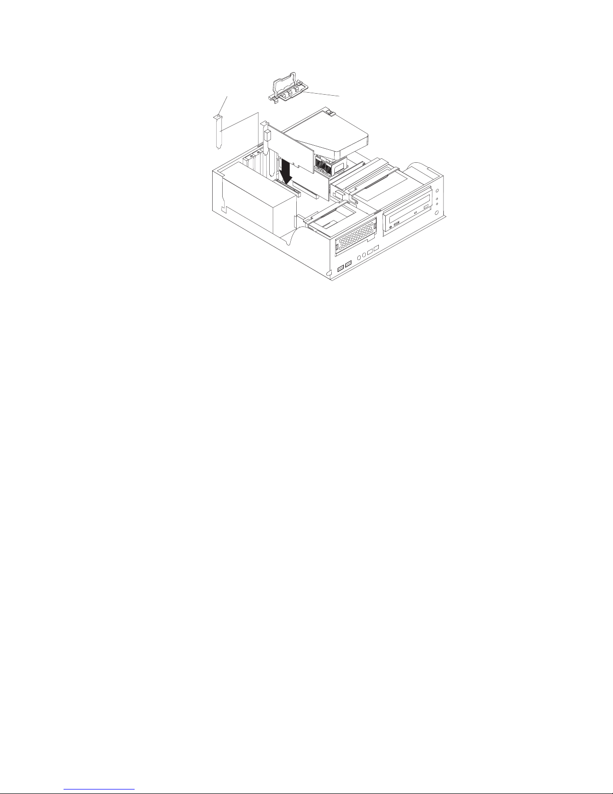
If
If
v
v
36
Expansion-slot cover
11.
Connect required cables to the adapter. Route cables so that they do not block
Adapter-support bracket
the flow of air from the fans.
12.
13.
you have another adapter to install, repeat steps 1 through 9.
Reinstall the rear adapter-support bracket; then, rotate the bracket to the
closed (locked) position.
14.
Replace the frame-support bracket.
15.
you have other options to install, do so now; otherwise, replace the cover
(see “Replacing the cover” on page 48), reconnect the external cables and
power cords, and turn on the computer.
Installing internal drives
Depending on your computer model, one or more of the following drives might be
installed in your computer:
Hard disk
CD-ROM, CD-RW, or DVD/CD-RW combo
IBM IntelliStation M Pro Types 6220 and 6230: User’s Guide
Page 59
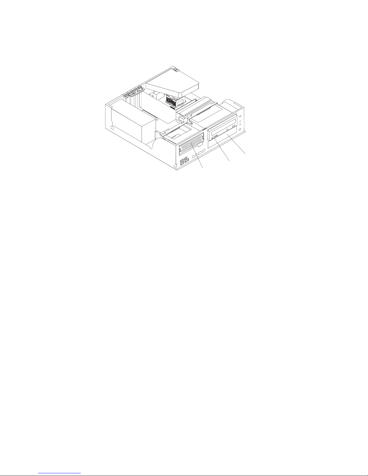
or
1.
2.
3.
3. 4.
or
5.
Internal drive bays
Your computer M Pro Type 6220 computer comes with an IDE CD-ROM, CD-RW,
DVD/CD-RW drive in bay 2 and a hard disk drive in bay 3.
Bay 3
Bay 2
Bay 1
Notes:
Tape drives, CD-ROM, DVD/CD-RW, and DVD-ROM drives are examples of
removable-media drives. You can install removable-media drives in bay 2 only.
You have two serial ATA (SATA) hard disk drive connectors on the system
board. Each serial ATA drive comes with a cable.
You can mix and match parallel IDE or serial ATA hard disk drives in bays 1 and
The electromagnetic interference (EMI) integrity and cooling of the computer are
protected by having all bays and PCI slots covered or occupied. When you
install a drive or PCI adapter, save the EMC shield and filler panel from the bay
the PCI adapter slot cover in the event you later remove the option.
For a complete list of supported options for your computer, go to
http://www.ibm.com/pc/; then, select your country and navigate to the list of
options for your computer.
Chapter 4. Installing options
37
Page 60

1.
2.
3.
4.
to
1.
2.
3.
4.
5.
6.
on a
7.
8.
38
Preinstallation steps
Some of these steps are required only the first time you install a hard disk drive in a
specific bay:
Read the safety information beginning on page vii, and the guidelines in
“Handling static-sensitive devices” on page 29, and the documentation that
comes with your drive.
Verify that you have all the cables and other equipment specified in the
documentation that comes with the drive.
Choose the bay in which you want to install the drive.
Check the instructions that come with the drive to determine whether you need
set any switches or jumpers on the drive.
Installing a hard disk drive in bay 1
Complete the following steps to install a drive in bay 1:
Follow the instructions in “Preinstallation steps.”
Turn off the computer and attached devices.
Disconnect all power cords; then, disconnect all external cables.
Remove the cover and frame-support bracket. See “Removing the cover” on
page 33 and “Removing and installing the support bracket” on page 33 for
details.
Rotate the drive bay cage until the latch catches the front of the computer
chassis.
Touch the static-protective package containing the drive to any unpainted metal
surface on the computer; then, remove the drive from the package and place it
static-protective surface.
Set any jumpers or switches on the drive according to the documentation that
comes with the drive.
Slide the drive into the drive bay, and then attach the drive to the drive cage
with the screws.
IBM IntelliStation M Pro Types 6220 and 6230: User’s Guide
Page 61

to
If
1.
2.
3.
4.
5.
9.
Connect one end of the parallel IDE or serial ATA signal cable into the back of
the drive and the other end of the cable into the parallel IDE or serial ATA
connector on the system board. For the location of the parallel IDE or serial
ATA connectors, see “System-board internal connectors” on page 32
Note: Make sure to route the signal cable so that it does not block the airflow
the rear of the drives or over the microprocessor.
10.
Connect the power cable to the back of the drive. The connectors are keyed
and can be inserted only one way.
11.
you have other options to install or remove, do so now.
12.
Replace the cover and frame-support bracket. See “Replacing the cover” on
page 48 and “Removing and installing the support bracket” on page 33 for
details.
13.
Reconnect the external cables and power cords; then, turn on the attached
devices and the computer.
Installing a drive in bay 2
Complete the following steps to install or replace a drive in bay 2:
Follow the instructions in “Preinstallation steps” on page 38.
Turn off the computer and attached devices.
Disconnect all power cords; then, disconnect all external cables.
Remove the cover and frame-support bracket. See “Removing the cover” on
page 33 and “Removing and installing the support bracket” on page 33 for
details.
Disconnect power and signal cables to the drive.
Chapter 4. Installing options
39
Page 62
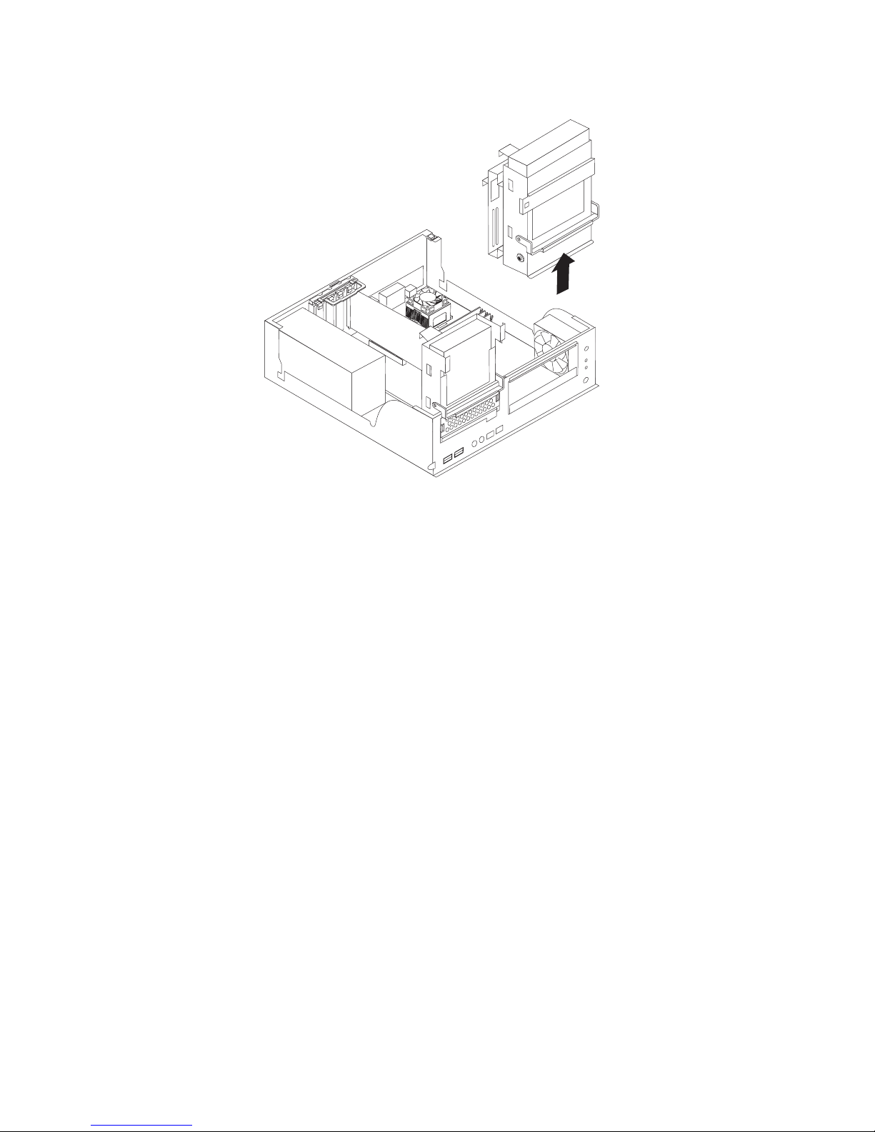
7.
8.
40
6.
Rotate the hard disk drive cage and remove it from the computer.
Remove the screws holding the drive in place.
Slide the drive out of the drive bay from the front of the drive bay.
IBM IntelliStation M Pro Types 6220 and 6230: User’s Guide
Page 63

or
v Do
v
9.
Note: If you are installing a drive that contains a laser, observe the following
safety precaution.
Statement 3:
CAUTION:
When laser products (such as CD-ROMs, DVD drives, fiber optic devices,
transmitters) are installed, note the following:
not remove the covers. Removing the covers of the laser product
could result in exposure to hazardous laser radiation. There are no
serviceable parts inside the device.
Use of controls or adjustments or performance of procedures other
than those specified herein might result in hazardous radiation
exposure.
DANGER
Some laser products contain an embedded Class 3A or Class 3B laser
diode. Note the following.
Laser radiation when open. Do not stare into the beam, do not view
directly with optical instruments, and avoid direct exposure to the
beam.
Touch the static-protective package containing the new drive to any unpainted
metal surface on the computer; then, remove the drive from the package and
place it on a static-protective surface.
10.
Follow the instructions that come with the drive to set jumpers or switches, if
any.
Chapter 4. Installing options
41
Page 64

to
If
1.
2.
3.
4.
5.
42
11.
Slide the drive into the drive bay from the front, and then attach the drive to
the drive cage.
12.
Place the drive cage back into the computer.
13.
Connect one end of the IDE signal cable into the back of the drive and the
other end of the cable into the IDE connector on the system board. For the
location of the IDE connectors, see “System-board internal connectors” on
page 32
Note: Make sure to route the signal cable so that it does not block the airflow
the rear of the drives or over the microprocessor.
14.
Connect the power cable to the back of the drive. The connectors are keyed
and can be inserted only one way.
15.
16.
you have other options to install or remove, do so now.
Replace the cover and frame-support bracket. See “Replacing the cover” on
page 48 and “Removing and installing the support bracket” on page 33 for
details.
17.
Reconnect the external cables and power cords; then, turn on the attached
devices and the computer.
Installing a hard disk drive in bay 3
Complete the following steps to replace or install a hard disk drive in bay 3:
Follow the instructions in “Preinstallation steps” on page 38.
Turn off the computer and attached devices.
Disconnect all power cords; then, disconnect all external cables.
Remove the cover and frame-support bracket. See “Removing the cover” on
page 33 and “Removing and installing the support bracket” on page 33 for
details.
Disconnect the power and signal cables from both drives in the drive cage.
IBM IntelliStation M Pro Types 6220 and 6230: User’s Guide
Page 65
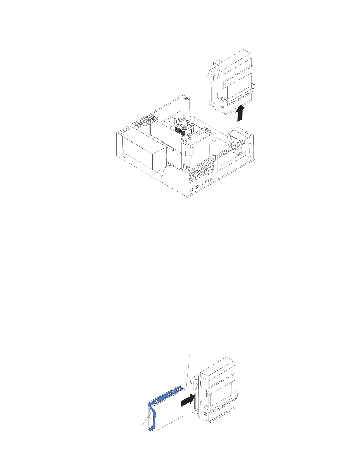
7.
8.
9.
6.
Remove the drive cage from the computer.
Slide the existing drive out of the drive bay. Remove the drive from the drive
tray by gently pulling both sides of the drive tray outward until the mounting
pins are disengaged from the holes on the drive; then, lift the drive out of the
drive tray.
Touch the static-protective package containing the new drive to any unpainted
metal surface on the computer; then, remove the drive from the package and
place it on a static-protective surface.
Set any jumpers or switches on the new drive according to the documentation
that comes with the drive.
10.
Attach the new drive to the drive tray. Place the drive on the drive tray and
align the holes on the drive with the mounting pins on the drive tray. Gently
pull both sides of the drive tray outward and insert the mounting pins into the
holes on the drive.
11.
Slide the drive into the drive bay until the drive snaps into place, and place the
drive cage back into the computer.
Important: The following illustration shows where the connectors on the
parallel IDE and serial ATA (SATA) drives should be located when you install
the drive in the drive tray.
Connectors on
Serial ATA drive
Connectors
on IDE drive
Chapter 4. Installing options
43
Page 66

If
to
If
v
v
v If
v If
v If
v
At
at
v
–
44
12.
you are installing a parallel IDE or serial ATA device, connect one end of the
parallel IDE or serial ATA signal cable into the back of the drive and the other
end of the cable into the parallel IDE or serial ATA connector on the system
board. For the location of the parallel IDE or serial ATA connectors, see
“System-board internal connectors” on page 32.
Note: Make sure to route the signal cable so that it does not block the airflow
the rear of the drives or over the microprocessor.
13.
Connect a power cable to the back of the drive. The connectors are keyed and
can be inserted only one way.
14.
15.
you have other options to install or remove, do so now.
Replace the support bracket. See “Removing and installing the support
bracket” on page 33.
16.
Replace the cover. See “Replacing the cover” on page 48 for details.
17.
Reconnect the external cables and power cords; then, turn on the attached
devices and the computer.
Power and signal cables for internal drives
Your computer uses cables to connect parallel IDE and serial ATA devices to the
power supply and to the system board. (See “System-board internal connectors” on
page 52 for the location of system-board connectors.) Review the following
information before connecting power and signal cables to internal drives:
The drives that are preinstalled in your computer come with power and signal
cables attached. If you replace any drives, remember which cable is attached to
which drive.
When you install a drive, ensure that one of the drive connectors of the signal
cable is connected to the drive and that the connector at the other end of the
signal cable is connected to the system board.
you have only one IDE device on a cable, it must be set as a master device.
two IDE devices are used on a single cable, one must be designated as the
master device and the other as the subordinate device; otherwise, the computer
might not recognize some of the IDE devices. The master and subordinate
designation is determined by switch or jumper settings on each IDE device.
two IDE devices are on a single cable and only one is a hard disk drive, the
hard disk drive must be set as a master device.
The following cables are provided:
Power cables: Four-wire power cables connect the drives to the power supply.
the end of these cables are plastic connectors that can be attached to
different drives; these connectors vary in size. You can use either a four-wire
power cable or serial ATA power cable with serial ATA drives, but do not use both
the same time (use one or the other).
Signal cables: Signal cables are typically flat cables, also called ribbon cables,
that connect parallel IDE and serial ATA drives to the system board. Two or three
types of signal cable come with your computer:
IDE: The wider IDE signal cable has three connectors. One of these
connectors is attached to the drive, one is a spare, and the third is attached to
the master or subordinate IDE connector on the system board. The spare
connector can be used to connect additional IDE drives to your computer.
The CD-ROM drive is attached an ATA 100 signal cable. ATA 100 signal
cables are color-coded. The blue connector is attached to the system board.
The black connector is attached to the master IDE device. The gray middle
connector is attached to the subordinate IDE device. If you are installing an
IBM IntelliStation M Pro Types 6220 and 6230: User’s Guide
Page 67

–
1.
2.
or
3.
4.
5.
6.
7.
8.
a
additional hard disk drive, you must change the switch or jumper setting on
the CD-ROM drive to make the drive a subordinate device, set the switch or
jumper setting on the new drive to master, and change the connector used for
the CD-ROM drive to the gray middle connector. The new drive will be
connected to the black master IDE device connector.
Serial ATA: The narrower, black signal cable has two connectors. One is
attached to the serial ATA drive, and the other is attached to the connector on
the system board. Each serial ATA drive comes with a cable. If you install an
additional serial ATA drive, you will need an additional cable.
Installing memory modules
The following notes describe the types of dual inline memory modules (DIMMs) that
your computer supports and other information that you must consider when
installing DIMMs.
Notes:
When you restart the computer after adding or removing a DIMM, the computer
displays a message that the memory configuration has changed.
Your IntelliStation M Pro Type 6220 computer uses industry-standard, PC2700
PC3200 double-data-rate (DDR) dual inline memory modules (DIMMs).
The system board contains four DIMM connectors and supports two-way
memory interleaving.
The DIMM options available for your computer are 256 MB, 512 MB, and 1 GB
memory modules . Your computer supports a minimum of 256 MB and a
maximum of 4 GB of system memory.
The amount of usable memory will be reduced depending on the system
configuration. A certain amount of memory must be reserved for system
resources. The BIOS will display the total amount of installed memory and the
amount of configured memory.
Your computer comes with either one or two 256 MB, 512 MB, or 1 GB memory
DIMMs installed. If your computer has one DIMM installed, when you install an
additional DIMM, it must be installed in DIMM 3 memory connector and must be
the same size, speed, type, and technology as the DIMM installed in DIMM 1
memory connector. You can mix compatible DIMMs from various manufacturers.
When one DIMM is installed in the computer, the computer runs as a
single-channel computer. When you add a DIMM in DIMM 3 memory connector,
your computer defaults to a dual-channel computer.
DIMMs must be installed in matched pairs. The first pair of DIMMs you install in
DIMM 1 and DIMM 3 memory connectors must be the same size, speed, type,
and technology. You can mix compatible DIMMs from various manufactures. If
you install a second pair of DIMMs in DIMM 2 and DIMM 4 memory connectors,
they do not have to be the same size, speed, type, and technology as the
DIMMs installed in DIMM 1 and DIMM 3 memory connectors. However, the size,
speed, type, and technology of the DIMMs you install in DIMM 2 and DIMM 4
memory connectors must match each other.
Install only 2.5 V, 184-pin, double-data-rate (DDR) 333 or 400, PC2700 or
PC3200, unbuffered synchronous dynamic random-access memory (SDRAM)
with error correcting code (ECC) DIMMs. These DIMMs must be compatible
with the latest PC2700 or PC3200 SDRAM unbuffered DIMM specification. For
list of supported options for your computer, go to http://www.ibm.com/pc/;
then, select your country and navigate to the list of options for your computer.
Complete the following steps to install a DIMM:
Chapter 4. Installing options
45
Page 68

2.
on
3.
4.
5.
6.
be
4
1
1 2
1, 3 4
1, 2, 3, 4 7.
8.
9.
so
46
1.
Read the safety information beginning on page vii and the guidelines in
“Handling static-sensitive devices” on page 29.
Turn off the computer and all attached devices (see “Turning off the computer”
page 20); then, disconnect all power cords and external cables.
Remove the cover (see “Removing the cover” on page 33).
Remove the support bracket (see “Removing and installing the support
bracket” on page 33).
For easier access to the memory modules, rotate the drive cage out of the
computer. Grasp the drive cage and rotate it until it locks into place.
Locate the DIMM connectors on the system board. Determine the connectors
into which you will install the DIMMs. Remember, DIMM 1 and DIMM 3 must
paired together (and must be the first pair installed) and DIMM 2 and DIMM
must be paired together. The following illustration shows the DIMM
installation sequence.
Memory installation sequence
DIMMs
DIMM
DIMMs
DIMMs
Slots
Open the retaining clips and, if necessary, remove any existing DIMM.
Touch the static-protective package containing the DIMM to any unpainted
metal surface on the computer. Then, remove the new DIMM from the
package.
Gently open the retaining clip on each end of the DIMM slot. Turn the DIMM
that the pins align correctly with the connector.
10.
Insert the DIMM into the connector. Firmly press the DIMM straight down into
the connector by applying pressure on both ends of the DIMM simultaneously.
The retaining clips snap into the locked position when the DIMM is firmly
seated in the connector. If a gap exists between the DIMM and the retaining
clips, the DIMM has not been correctly installed. Open the retaining clips,
IBM IntelliStation M Pro Types 6220 and 6230: User’s Guide
Page 69

If
To
v A
v An
v A 19 mm
v
v A
v A
1.
2.
3.
remove the DIMM, then reinsert it.
DIMM
connector 1
DIMM
connector 2
DIMM
connector 3
DIMM
connector 4
11.
you have other options to install or remove, do so now. Otherwise, rotate the
drive cage back into the computer and replace the support bracket (see
“Removing and installing the support bracket” on page 33).
12.
Replace the cover (see “Replacing the cover” on page 48).
13.
Reconnect the external cables and power cords. Turn on the attached devices,
and turn on the computer.
Installing a security rope clip
help prevent hardware theft, you can add a security rope clip and cable to your
computer. After you add the security cable, make sure that it does not interfere with
other cables that are connected to the computer.
Before you begin, obtain the following items:
flat-blade screwdriver
adjustable wrench
(0.75 in.) rope clip or wire rope (similar to National Manufacturing
number 3230, stock number 176-735)
Threaded nuts that fit the rope clip
security cable
lock, such as a combination lock or padlock
Complete
the following steps to install a rope clip:
Turn off the computer and all attached devices. Disconnect all external cables
and power cords; then, remove the cover. See “Removing the cover” on page
33.
Use a screwdriver to remove the two metal knockouts.
Insert the rope clip through the rear panel; then, attach and tighten the nuts.
Chapter 4. Installing options
47
Page 70

or
5. If
6.
If
1.
2.
48
4.
Thread the cable through the rope clip and around an object that is not part of
permanently secured to the building structure or foundation and from which
the cable cannot be removed. Fasten the cable ends together with a lock. After
you add the security cable, make sure that it does not interfere with other
cables connected to the computer.
cover.
Reconnect the external cables and power cords. Turn on the attached devices,
and turn on the computer.
Replacing the cover
you removed the support bracket, reinstall it before you replace the cover. See
“Removing and installing the support bracket” on page 54.
Complete the following steps to replace the cover:
Make sure that all cables, adapters, and other components are installed and
seated correctly and that you have removed all work tools from inside the
computer.
Install the cover by placing it over the chassis and pivoting it down over the
computer until it snaps into place.
Rope clip
you have other options to install or remove, do so now; otherwise, replace the
IBM IntelliStation M Pro Types 6220 and 6230: User’s Guide
Page 71

3.
Reconnect the external cables and power cords. Turn on the attached devices,
and turn on the computer.
Chapter 4. Installing options
49
Page 72

M
50
Installing options in the M Pro Type 6230 (tower model)
This section provides instructions for installing hardware options in the IntelliStation
Pro Type 6230 computer.
Major components of your computer
The following illustration shows the major components in the M Pro Type 6230
tower computer.
Rear adapter
retention bracket
Memory modules
Microprocessor
System board
Support bracket
Cover
Keylock button
Hard disk
drive tray
4
9
13
Drive cage
Front adapter
retention bracket
EMC
shield
Filler
panel
IBM IntelliStation M Pro Types 6220 and 6230: User’s Guide
Page 73

System-board option connectors
The following illustration shows the system-board connectors for user-installable
options.
Microprocessor
and fan (U6)
AGP
PCI 1
PCI 2
PCI 3
DIMM 1
DIMM 2
DIMM 4
DIMM 3
Battery
Mini - PCI
PCI 4
PCI 5
Chapter 4. Installing options
51
Page 74
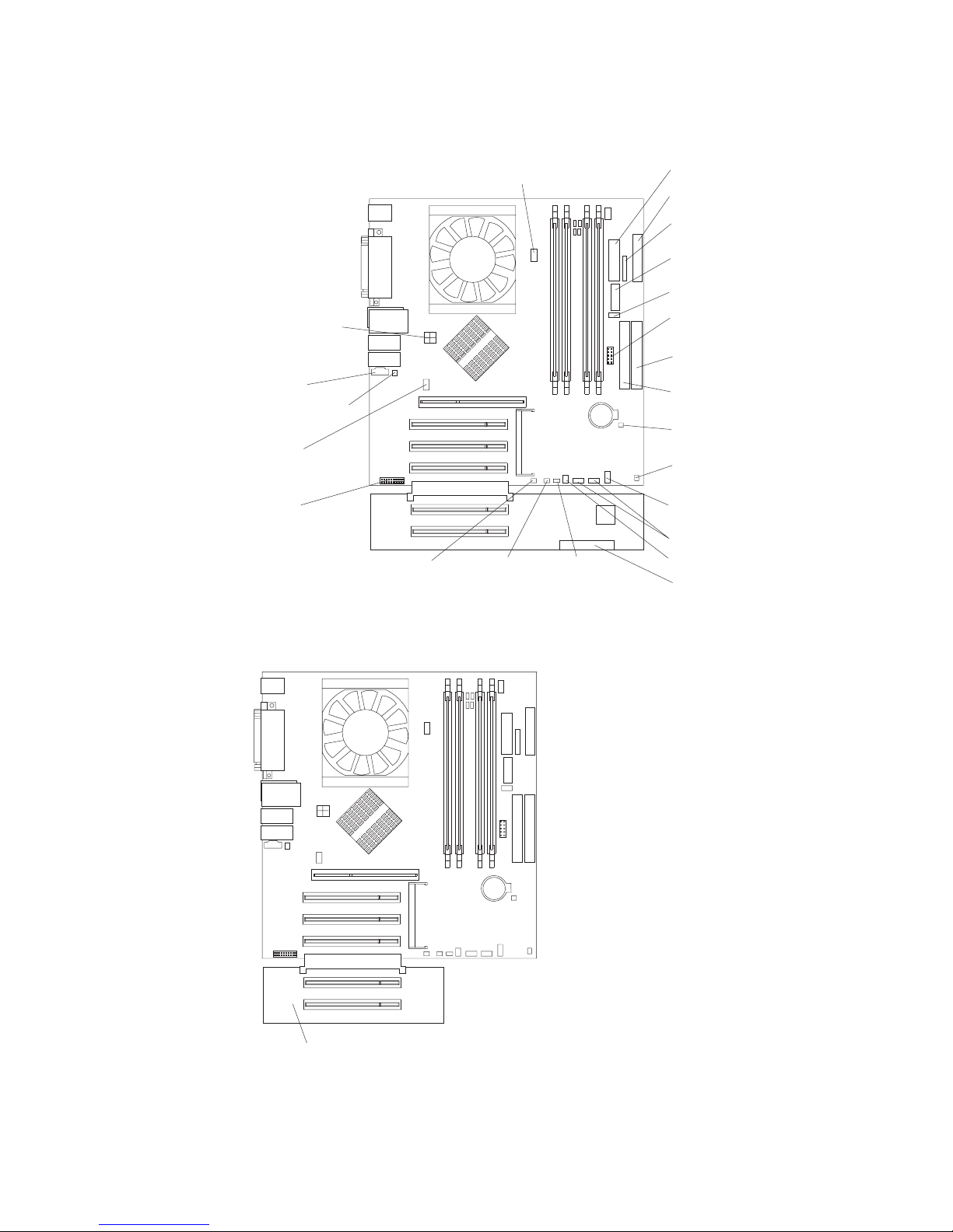
52
System-board internal connectors
The following illustration shows the internal connectors on the system board.
Microprocessor fan
connector
Main power
Diskette drive
Front panel
Powe r
Fan
Microprocessor
Front USB
power
Primary IDE
(PRI IDE)
CDROM
Internal speaker
connector
Secondary IDE
(SEC IDE)
Intrusion switch
Rear fan
Boot block
jumper
Speaker
connector
Wake on LAN
connector
®
Serial ATA connectors
Ethernet
activity LED
System
error LED
SCSI LED
connector
Fan
SCSI signal cable
The IDE models for Type 6230 have a shorter extender card, as shown in the
following illustration.
Extender card
IBM IntelliStation M Pro Types 6220 and 6230: User’s Guide
Page 75
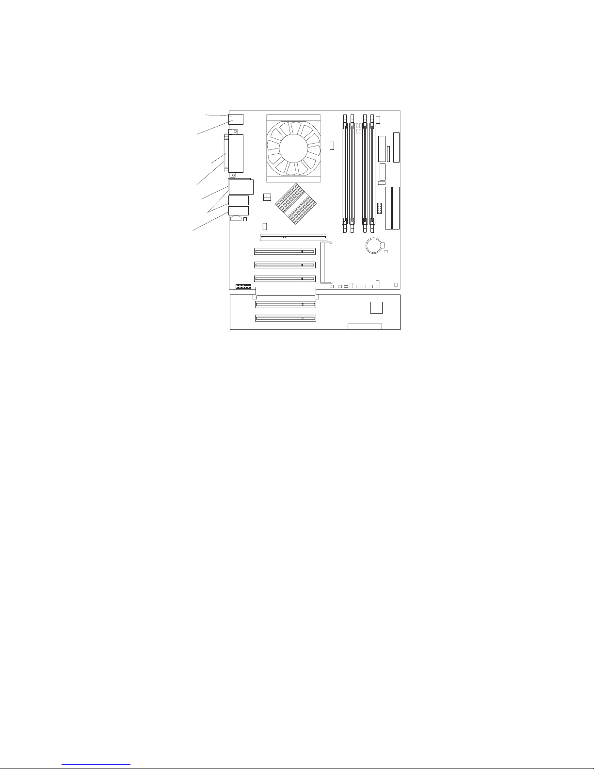
To
1.
2.
on
3.
System-board external connectors
The following illustration shows the external input/output port connectors on the
system board.
Keyboard
Mouse
Serial ports
Parallel
Ethernet
USB ports
Audio
Removing the side cover
remove the side cover, you might find it easier to lay the computer on its side.
Complete the following steps to remove the side cover of the computer:
Read the safety information beginning on page vii. and the guidelines in
“Handling static-sensitive devices” on page 29.
Turn off the computer and all attached devices (see “Turning off the computer”
page 20).
Disconnect all external cables and power cords.
Chapter 4. Installing options
53
Page 76

1.
2.
3.
54
4.
Pull the cover-release latch away from the computer, and push the cover toward
the rear of the computer. Lift the side cover off the computer and set it aside.
1394
For instructions for replacing the side cover, see “Replacing the side cover” on page
68.
Attention: For proper cooling and airflow, replace the cover before turning on the
computer. Operating the computer with the cover removed might damage computer
components.
Removing and installing the support bracket
When working with some devices, such as hard disk drives, adapters, and memory
modules, you must first remove the support bracket to access the device.
Complete the following steps to remove the support bracket:
Read safety information beginning on page vii and the guidelines in “Handling
static-sensitive devices” on page 29.
Remove the side cover (“Removing the side cover” on page 53).
Pull out on the rear end of the support bracket approximately 150 mm (6 in.).
IBM IntelliStation M Pro Types 6220 and 6230: User’s Guide
Page 77
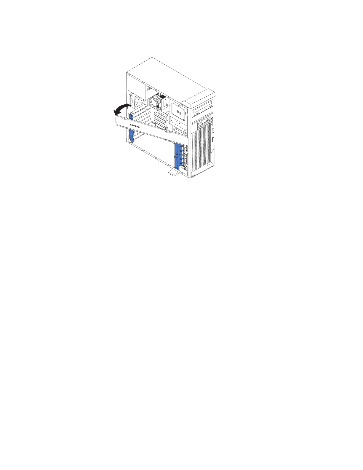
To
up to
v
v
v
v
v
v
v
4.
Disengage the front end of the support bracket from the computer and set the
bracket aside.
94
3
1
reinstall the support bracket, reverse the previous steps.
Working with adapters
Your computer comes with adapter connectors or slots. The Accelerated Graphics
Port (AGP) video adapter is installed in the AGP slot and some models have a
IEEE 1394 (FireWire) controller adapter installed in the mini-PCI slot. You can install
five additional optional adapters in your computer in PCI slots 1 through 5.
See “System-board option connectors” on page 51 for the locations of expansion
slots on the system board.
Adapter considerations
The following notes describe the types of adapters that your computer supports and
other information that you might consider when installing an adapter:
Read the documentation that comes with your operating system.
Locate the documentation that comes with the adapter and follow those
instructions in addition to the instructions in this chapter. If you need to change
the switch or jumper settings on your adapter, follow the instructions that come
with the adapter.
Your computer comes with adapter connectors or slots. The Accelerated
Graphics Port (AGP) video adapter is installed in the AGP slot and some models
have an IEEE 1394 (FireWire) adapter installed in the mini-PCI slot. You can
install up to five additional optional adapters in your computer in PCI slots 1
through 5.
You can install only 32-bit adapters in the 32-bit PCI slots 1 through 5.
You can install full-length adapters in all five expansion slots. None of the
expansion slots are hot-plug slots.
Your computer supports 5.0 V signaling and universal PCI adapters; it does not
support 3.3 V signaling adapters.
The system scans the AGP slot, mini-PCI slot, and PCI expansion slots 1
through 5 to assign system resources. Then, the system starts the PCI devices in
the following order, if you have not changed the default startup sequence: AGP
Chapter 4. Installing options
55
Page 78

v
do
v
1.
2.
on
3.
4.
5.
6. If
If
7.
8.
56
slot, mini-PCI slot, PCI expansion slot 1, system-board integrated drive
electronics (IDE) or small computer system interface (SCSI) devices, and then
PCI slots 2 through 5.
Some models come with a IEEE 1394 (FireWire) adapter installed in the mini-PCI
slot. If your computer did not come with a IEEE 1394 (FireWire) adapter installed,
not install any adapter in the mini-PCI slot.
For a list of supported options for your computer, go to http://www.ibm.com/pc/;
then, select your country and navigate to the list of options for your computer.
Installing an adapter
Note: The AGP Pro slot and PCI slots 1, 2, and 3 must be empty for you to access
the IEEE 1394 (FireWire) adapter in the mini-PCI slot. If you are replacing
the IEEE 1394 (FireWire) adapter, the optional PCI adapter and the AGP
video adapter will need to be temporarily removed.
Complete the following steps to install an adapter in your computer:
Read the safety information beginning on page vii, and the guidelines in
“Handling static-sensitive devices” on page 29.
Turn off the computer and all attached devices (see “Turning off the computer”
page 20).
Disconnect all external cables and power cords; then, remove the side cover
(see “Removing the side cover” on page 53).
Determine which PCI slot you will use for the adapter. Check the instructions
that come with the adapter for any requirements, restrictions, or cabling
instructions. It might be easier to route cables before you install the adapter.
For full-length adapters, rotate the rear adapter-retention bracket to the open
(unlocked) position and remove it from the computer. Rotate the front
adapter-retention bracket to the open position. If you are installing a smaller
adapter, remove only the rear adapter-retention bracket.
there is an adapter already installed in the slot, remove it and place it on a
static-protective surface.
the slot is empty, remove the expansion-slot cover. From the rear of the
computer, press on the slot cover. Grasp it and pull it out of the expansion slot.
Store it in a safe place for future use.
Attention: Expansion-slot covers must be installed on all vacant slots. This
maintains the electronic emissions standards of the computer and ensures
proper ventilation of computer components.
Follow the instructions that come with the adapter to set jumpers or switches, if
any.
Remove the adapter from the static-protective package, carefully grasp the
adapter by the top edge or upper corners, and align it with the expansion slot
guides; then, press the adapter firmly into the expansion slot. Move the
adapter directly from the static-protective package to the adapter slot. Avoid
touching the components and gold-edge connectors on the adapter.
Attention: Make sure that the adapter is correctly seated in the expansion
slot before you turn on the computer. Incomplete installation of an adapter
might damage the system board or the adapter
IBM IntelliStation M Pro Types 6220 and 6230: User’s Guide
Page 79
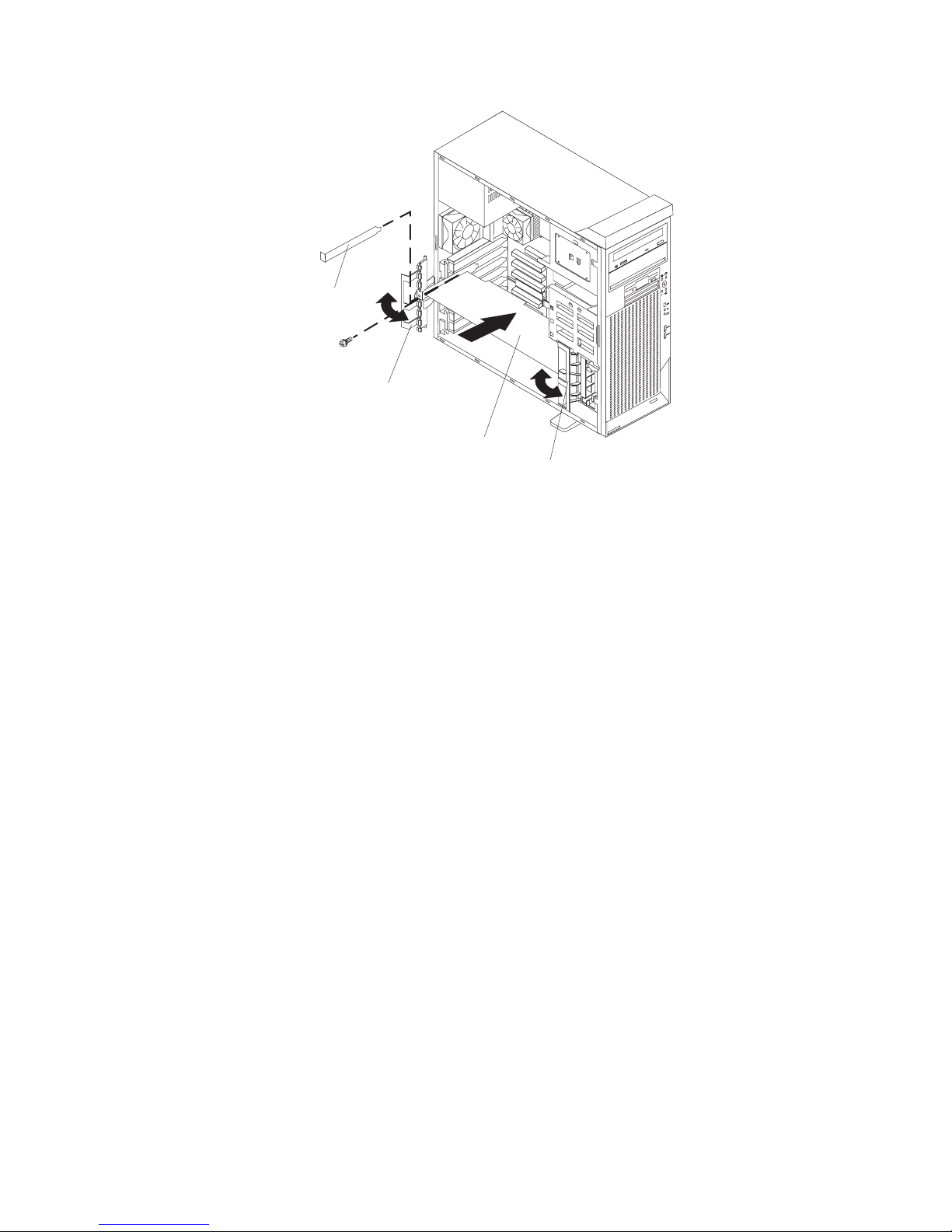
If
If
If
Expansion
slot cover
4
9
13
Rear
adapter
retention
bracket
Adapter
Front
adapter
retention
bracket
9.
Connect required cables to the adapter. Route cables so that they do not block
the flow of air from the fans. If you are installing an optional SCSI adapter, see
“Cabling an optional SCSI adapter” on page 58 for additional information.
10.
11.
you have another adapter to install, repeat steps 4 through 9.
you have installed a full-length adapter, rotate the front adapter-support
bracket to the closed (locked) position.
Note: If any adapter in your computer is large or has heavy cables attached to
it, you can secure the adapter with a screw: insert one backup
expansion-slot screw (stored on the frame-support bracket) through the
top of each adapter bracket into the screw hole and secure the adapter
before proceeding to the next step. If you use a screw to secure an
adapter, you will need to secure all adapters with screws. You cannot
use both the screws and the retention brackets to secure an adapter.
You must use one or the other.
12.
Reinstall the rear adapter-retention bracket; then, rotate the bracket to the
closed (locked) position.
Note: The rear retention bracket rests against the computer side cover. You
13.
you have other options to install, do so now; otherwise, continue with step
14.
14.
Replace the support bracket (see “Removing and installing the support
bracket” on page 54).
15.
Replace the side cover (see “Replacing the side cover” on page 68).
16.
Reconnect the external cables and power cords; then, turn on the attached
devices and the computer.
might find it easier to lay the computer on its side to replace the side
cover.
Chapter 4. Installing options
57
Page 80

1. An
2.
1.
2.
3.
4.
58
Cabling an optional SCSI adapter
You can install an optional SCSI adapter in your computer to control the internal
hard disk drives. With a SCSI adapter installed, you can configure the internal hard
disk drives into disk arrays. You can also cable a SCSI adapter to external hard
disk drives. See your SCSI adapter option documentation for complete instructions
for installing a SCSI adapter in your computer and for additional information about
SCSI adapters.
Notes:
optional SCSI adapter is required to connect external SCSI devices.
The SCSI cables used by the integrated SCSI controller cannot be used with an
optional SCSI adapter.
Complete the following steps to cable an optional SCSI adapter:
Install the SCSI adapter (see “Installing an adapter” on page 56).
Connect the SCSI-signal cable to the adapter and to one or more of the
signal-cable connectors on the rear of the SCSI devices.
Connect the SCSI-activity-indicator cable to the adapter and to the SCSI-LED
connector on the system board. See “System-board internal connectors” on
page 52 for the location of the SCSI-LED connector.
SCSI
signal
cable
Rear
adapter
support
bracket
1394
SCSI signal
cable connector
SCSI activity
indicator cable
connector
SCSI
adapter
SCSI
activity
indicator
cable
SCSI
LED
Front
adapter
support
bracket
Complete the installation of the optional SCSI adapter.
IBM IntelliStation M Pro Types 6220 and 6230: User’s Guide
Page 81

v
v
v
1.
2.
3.
4. To
5.
6.
7. 7.
or
8.
Installing internal drives
Depending on your computer model, one or more of the following drives might be
installed in your computer:
Diskette
Hard disk
CD-ROM, CD-RW, or DVD/CD-RW combo
Internal drive bays
Your IntelliStation M Pro computer comes with an IDE CD-ROM or DVD/CD-RW
drive in bay 1, a 3.5-in., 1.44 MB diskette drive in bay 3, and a hard disk drive in
bay 6 or 7.
Bay 1
Bay 2
Bay 3
1394
Bay 4
Bay 5
Bay 6
Bay 7
Notes:
Diskette drives, tape drives, CD-ROM, DVD/CD-RW, and DVD-ROM drives are
examples of removable-media drives. You can install removable-media drives in
bays 1, 2, 3, and 4 only.
You can install a 3.5-in. slim-high or 5.25-in. half-high removable-media drive,
such as a tape backup drive, in bay 2.
The IntelliStation M Pro computer supports only one diskette drive.
install a 3.5-in. drive in a 5.25-in. bay, you must use the 5.25-in. conversion
kit, supplied with the option.
You have two serial ATA hard disk drive connectors on the system board.
You can mix and match parallel IDE and serial ATA drives in bays 2, 4, 5, 6, and
The electromagnetic interference (EMI) integrity and cooling of the computer are
protected by having all bays and PCI slots covered or occupied. When you
install a drive or PCI adapter, save the EMC shield and filler panel from the bay
the PCI adapter slot cover in the event you later remove the option.
For a complete list of supported options for your computer, go to
http://www.ibm.com/pc/; then, select your country and navigate to the list of
options for your computer.
Chapter 4. Installing options
59
Page 82

1.
2.
3.
4.
to
1.
2.
3.
4.
5.
60
Preinstallation steps
Some of these steps are required only the first time you install a hard disk drive in a
specific bay.
Read the safety information beginning on page vii, the guidelines in “Handling
static-sensitive devices” on page 29, and the documentation that comes with
your drive.
Verify that you have all the cables and other equipment specified in the
documentation that comes with the drive.
Choose the bay in which you want to install the drive.
Check the instructions that come with the drive to determine whether you need
set any switches or jumpers on the drive. If you are installing a SCSI device,
make sure that you set the SCSI ID for that device.
Installing a drive in bay 2 or 4
Complete the following steps to install a drive in bay 2 or 4:
Follow the instructions in “Preinstallation steps” on page 60.
Turn off the computer and all attached devices.
Disconnect all external cables and power cords; then, remove the side cover
(see “Removing the side cover” on page 53).
Remove the support bracket (see “Removing and installing the support
bracket” on page 54).
Use a screwdriver to pry the filler panel and EMC shield away from the
computer.
Note: If you are installing a drive that contains a laser, observe the following
safety precaution.
IBM IntelliStation M Pro Types 6220 and 6230: User’s Guide
Page 83

or
v Do
v
6.
on a
7.
Statement 3:
CAUTION:
When laser products (such as CD-ROMs, DVD drives, fiber optic devices,
transmitters) are installed, note the following:
not remove the covers. Removing the covers of the laser product
could result in exposure to hazardous laser radiation. There are no
serviceable parts inside the device.
Use of controls or adjustments or performance of procedures other
than those specified herein might result in hazardous radiation
exposure.
DANGER
Some
laser products contain an embedded Class 3A or Class 3B laser
diode. Note the following.
Laser radiation when open. Do not stare into the beam, do not view
directly with optical instruments, and avoid direct exposure to the
beam.
EMC shield
Filler panel
1394
Touch the static-protective package containing the drive to any unpainted metal
surface on the computer; then, remove the drive from the package and place it
Follow the instructions that come with the drive to set jumpers or switches, if
any.
static-protective surface.
Chapter 4. Installing options
61
Page 84

8. If
9.
of
If
1.
2.
on
3.
4.
5.
62
Note: You might find it easier to install the new drive into the appropriate
opening on the front, and then attach the cables.
you are installing a 5.25-in. drive in bay 2, push the drive into the bay; then,
use the two screws to attach the drive to the drive cage. If you are installing a
3.5-in. drive in bay 2, you must attach the 5.25-in. conversion kit, supplied with
your option, to the 3.5-in. drive.
Determine whether the drive is an IDE or SCSI device; then, connect one end
the appropriate signal cable into the back of the drive and the other end of
this cable into the appropriate IDE or SCSI connector on the system board.
See “Power and signal cables for internal drives” on page 63 for additional
information about cabling drives and “System-board internal connectors” on
page 52 for the location of IDE and SCSI connectors on the system board. If
there are open connectors on the cables connecting existing IDE or SCSI
drives, these cables can be used to connect the new drive.
10.
Route the signal cable so that it does not block the airflow to the rear of the
drives or over the microprocessor.
11.
Connect the power cable to the back of the drive. The connectors are keyed
and can be inserted only one way.
12.
13.
you have other options to install or remove, do so now.
Replace the support bracket (see “Removing and installing the support
bracket” on page 54).
14.
Replace the side cover (see “Replacing the side cover” on page 68).
15.
Reconnect the external cables and power cords; then, turn on the attached
devices and the computer.
Installing a hard disk drive in bay 5, 6, or 7
Bays 5, 6, and 7 are in the drive cage. The drive cage is behind the front of the
adapter-support bracket.
Note: When installing options, you might find it easier to work with the computer
lying on its side.
Complete the following steps to install a drive in bay 5, 6, or 7:
Follow the instructions in “Preinstallation steps” on page 60.
Turn off the computer and all attached devices (see “Turning off the computer”
page 20).
Disconnect all external cables and power cords; then, remove the cover (see
“Removing the side cover” on page 53).
Remove the support bracket (see “Removing and installing the support
bracket” on page 54).
Grasp the drive cage and rotate the cage out of the computer until it locks into
place with the drive-cage retention tab and the open ends of the drive slots
and installed drives are facing you. Ensure that the drive cage locks into place
over the drive-cage retention tab by rotating the drive cage all the way out of
IBM IntelliStation M Pro Types 6220 and 6230: User’s Guide
Page 85

6.
7.
8.
9.
If
on
the computer.
4
9
13
4
139
Slide the existing drive out of the drive bay. Remove the drive from the drive
tray by gently pulling both sides of the drive tray outward until the mounting
pins are disengaged from the holes on the drive; then, lift the drive out of the
drive tray.
Touch the static-protective package containing the new drive to any unpainted
metal surface on the computer; then, remove the drive from the package and
place it on a static-protective surface.
Set any jumpers or switches on the new drive according to the documentation
that comes with the drive.
Attach the new drive to the drive tray. Place the drive on the drive tray and
align the holes on the drive with the mounting pins on the drive tray. Gently
pull both sides of the drive tray outward and insert the mounting pins into the
holes on the drive.
10.
Slide the drive into the drive bay until the drive snaps into place.
11.
Determine whether the drive is a parallel IDE, serial ATA, or SCSI device; then,
connect one end of the appropriate signal cable into the back of the drive and
the other end of this cable into the appropriate parallel IDE, serial ATA, or SCSI
connector on the system board. See “Power and signal cables for internal
drives” for additional information about cabling drives and “System-board
internal connectors” on page 52 for the location of parallel IDE, serial ATA, and
SCSI connectors on the system board. If there are open connectors on the
cables connecting existing parallel IDE, serial ATA, or SCSI drives, these
cables can be used to connect the new drive.
12.
Route the signal cable so that it does not block the airflow to the rear of the
drives or over the microprocessor.
13.
Connect the power cable to the back of the drive. The connectors are keyed
and can be inserted only one way.
14.
Push the drive cage outward, and press in on the drive-cage release tab; then,
rotate the cage back into the computer.
15.
16.
you have other options to install or remove, do so now.
Replace the support bracket (see “Removing and installing the support
bracket” on page 54).
17.
Replace the side cover (see “Replacing the side cover” on page 68).
18.
Reconnect the external cables and power cords; then, turn on the attached
devices and the computer.
Power and signal cables for internal drives
Your computer uses cables to connect parallel IDE, serial ATA, and SCSI devices to
the power supply and to the system board. (See “System-board internal connectors”
page 52
Chapter 4. Installing options
63
Page 86

v
v
v If
v If
v If
v
At
at
v
–
–
–
–
- An
64
on page 52 for the location of system-board connectors.) Review the following
information before connecting power and signal cables to internal drives:
The drives that are preinstalled in your computer come with power and signal
cables attached. If you replace any drives, remember which cable is attached to
which drive.
When you install a drive, ensure that one of the drive connectors of the signal
cable is connected to the drive and that the connector at the other end of the
signal cable is connected to the system board.
you have only one IDE device on a cable, it must be set as a master device.
two IDE devices are used on a single cable, one must be designated as the
master device and the other as the subordinate device; otherwise, the computer
might not recognize some of the IDE devices. The master and subordinate
designation is determined by switch or jumper settings on each IDE device.
two IDE devices are on a single cable and only one is a hard disk drive, the
hard disk drive must be set as a master device.
The following cables are provided:
Power cables: Four-wire power cables connect the drives to the power supply.
the end of these cables are plastic connectors that can be attached to
different drives; these connectors vary in size. You can use either a four-wire
power cable or serial ATA power cable with serial ATA drives, but do not use both
the same time (use one or the other).
Signal cables: Signal cables are typically flat cables, also called ribbon cables,
that connect parallel IDE, serial ATA, SCSI, and diskette drives to the system
board. Two or three types of signal cable come with your computer:
IDE: The wider IDE signal cable has three connectors. One of these
connectors is attached to the drive, one is a spare, and the third is attached to
the master or subordinate IDE connector on the system board. The spare
connector can be used to connect additional IDE drives to your computer.
The CD-ROM drive is attached an ATA 100 signal cable. ATA 100 signal
cables are color-coded. The blue connector is attached to the system board.
The black connector is attached to the master IDE device. The gray middle
connector is attached to the subordinate IDE device. If you are installing an
additional hard disk drive, you must change the switch or jumper setting on
the CD-ROM drive to make the drive a subordinate device, set the switch or
jumper setting on the new drive to master, and change the connector used for
the CD-ROM drive to the gray middle connector. The new drive will be
connected to the black master IDE device connector.
Diskette drive: The narrower signal cable has two connectors. One is
attached to the diskette drive, and the other is attached to the connector
(FDD1) on the system board.
Serial ATA: The narrower, black signal cable has two connectors. One
attaches to the serial ATA drive, and the other attaches to the connector on
the system board. Each serial ATA drive comes with a cable. If you install an
additional serial ATA drive, you will need an additional cable.
SCSI: The following cables can be used to attach SCSI devices to the
integrated SCSI controller on the system board:
Ultra320 twisted ribbon cable connects the internal Ultra320 SCSI hard
disk drive to the SCSI connector on the system board. This cable has four
additional connectors for attaching more internal SCSI devices.
IBM IntelliStation M Pro Types 6220 and 6230: User’s Guide
Page 87

A
1.
2.
3.
4.
5.
6.
7.
8.
1.
2.
on
3.
-
round SCSI cable connects external SCSI devices to the integrated SCSI
controller on the system board. For more information about connecting
SCSI devices, see the SCSI documentation.
Installing memory modules
The following notes describe the types of dual inline memory modules (DIMMs) that
your computer supports and other information that you must consider when
installing DIMMs:
Notes:
When you restart the computer after adding or removing a DIMM, the computer
displays a message that the memory configuration has changed.
Your IntelliStation M Pro Type 6230 computer uses industry-standard PC2700 or
PC3200 double-data-rate (DDR) dual inline memory modules (DIMMs).
The system board contains four DIMM connectors and supports two-way
memory interleaving.
The DIMM options available for your computer are 256 MB, 512 MB, and 1
GB. Your computer supports a minimum of 256 MB and a maximum of 4 GB of
system memory.
The amount of usable memory will be reduced depending on the system
configuration. A certain amount of memory must be reserved for system
resources. The BIOS code will display the total amount of installed memory and
the amount of configured memory.
Your computer comes with either one or two 256 MB, 512 MB, or 1 GB memory
DIMMs installed. If your computer has one DIMM installed, when you install an
additional DIMM, it must be installed in DIMM 3 memory connector and must be
the same size, speed, type, and technology as the DIMM installed in DIMM 1
memory connector. You can mix compatible DIMMs from various manufacturers.
When one DIMM is installed in the computer, the computer runs as a
single-channel computer. When you add a DIMM in DIMM 3 memory connector,
your computer defaults to a dual-channel computer.
DIMMs must be installed in matched pairs. The first pair of DIMMs you install in
DIMM 1 and DIMM 3 memory connectors must be the same size, speed, type,
and technology. You can mix compatible DIMMs from various manufactures. If
you install a second pair of DIMMs in DIMM 2 and DIMM 4 memory connectors,
they do not have to be the same size, speed, type, and technology as the
DIMMs installed in DIMM 1 and DIMM 3 memory connectors. However, the size,
speed, type, and technology of the DIMMs you install in DIMM 2 and DIMM 4
memory connectors must match each other.
Install only 2.5 V, 184-pin, double-data-rate (DDR), PC2700 or PC3200,
unbuffered synchronous dynamic random-access memory (SDRAM) with error
correcting code (ECC) DIMMs. These DIMMs must be compatible with the latest
PC2700 or PC3200 SDRAM unbuffered DIMM specification. For a list of
supported options for your computer, go to http://www.ibm.com/pc/; then, select
your country and navigate to the list of options for your computer.
Complete the following steps to install a DIMM:
Read the safety information beginning on page vii, and the guidelines in
“Handling static-sensitive devices” on page 29.
Turn off the computer and all attached devices (see “Turning off the computer”
Disconnect all external cables and power cords; then, remove the side cover
(see “Removing the side cover” on page 53.)
page 20).
Chapter 4. Installing options
65
Page 88

5.
6.
7.
be
4
1
1 2
1, 3 4
1, 2, 3, 4 8.
9.
so
66
4.
Remove the side cover (see “Removing the side cover” on page 53).
Remove the support bracket (see “Removing and installing the support
bracket” on page 54).
For easier access to the memory modules, rotate the drive cage out of the
computer. Grasp the drive cage and rotate it until it locks into place.
Locate the DIMM connectors on the system board. Determine the connectors
into which you will install the DIMMs. Remember, DIMM 1 and DIMM 3 must
paired together (and must be the first pair installed) and DIMM 2 and DIMM
must be paired together. The following illustration shows the DIMM
installation sequence.
Memory installation sequence
DIMMs
DIMM
DIMMs
DIMMs
Slots
Open the retaining clips and, if necessary, remove any existing DIMM.
Touch the static-protective package containing the DIMM to any unpainted
metal surface on the computer. Then, remove the new DIMM from the
package.
10.
Gently open the retaining clip on each end of the DIMM slot. Turn the DIMM
that the pins align correctly with the connector.
11.
Insert the DIMM into the connector. Firmly press the DIMM straight down into
the connector by applying pressure on both ends of the DIMM simultaneously.
The retaining clips snap into the locked position when the DIMM is firmly
seated in the connector. If there is a gap between the DIMM and the retaining
clips, the DIMM has not been correctly installed. Open the retaining clips,
remove the DIMM; then, reinsert it.
DIMM
connector 1
DIMM
connector 2
DIMM
connector 3
DIMM
connector 4
IBM IntelliStation M Pro Types 6220 and 6230: User’s Guide
Page 89

If
To
v A
v An
v A 19 mm
v
v A
v A
1.
2.
3.
4.
5.
or
12.
13.
you have other options to install or remove, do so now.
Push the drive cage outward and press in on the drive-cage release tab; then,
rotate the cage back into the computer.
14.
Replace the support bracket (see “Removing and installing the support
bracket” on page 54).
15.
Replace the side cover (see “Replacing the side cover” on page 68).
16.
Reconnect the external cables and power cords. Turn on the attached devices,
and turn on the computer.
Installing a security rope clip
help prevent hardware theft, you can add a security rope clip and cable to your
computer. After you add the security cable, make sure that it does not interfere with
other cables that are connected to the computer.
Before you begin, obtain the following items:
flat-blade screwdriver
adjustable wrench
(0.75 in.) rope clip or wire rope (similar to National Manufacturing
number 3230, stock number 176-735)
Threaded nuts that fit the rope clip
security cable
lock, such as a combination lock or padlock
Complete
the following steps to install a rope clip:
Turn off the computer and all attached devices.
Disconnect all external cables and power cords; then, remove the side cover.
See “Removing the side cover” on page 53.
Use a screwdriver to remove the two metal knockouts.
Insert the rope clip through the rear panel; then, attach and tighten the nuts.
Thread the cable through the rope clip and around an object that is not part of
permanently secured to the building structure or foundation and from which
the cable cannot be removed. Fasten the cable ends together with a lock. After
you add the security cable, make sure that it does not interfere with other
Chapter 4. Installing options
67
Page 90
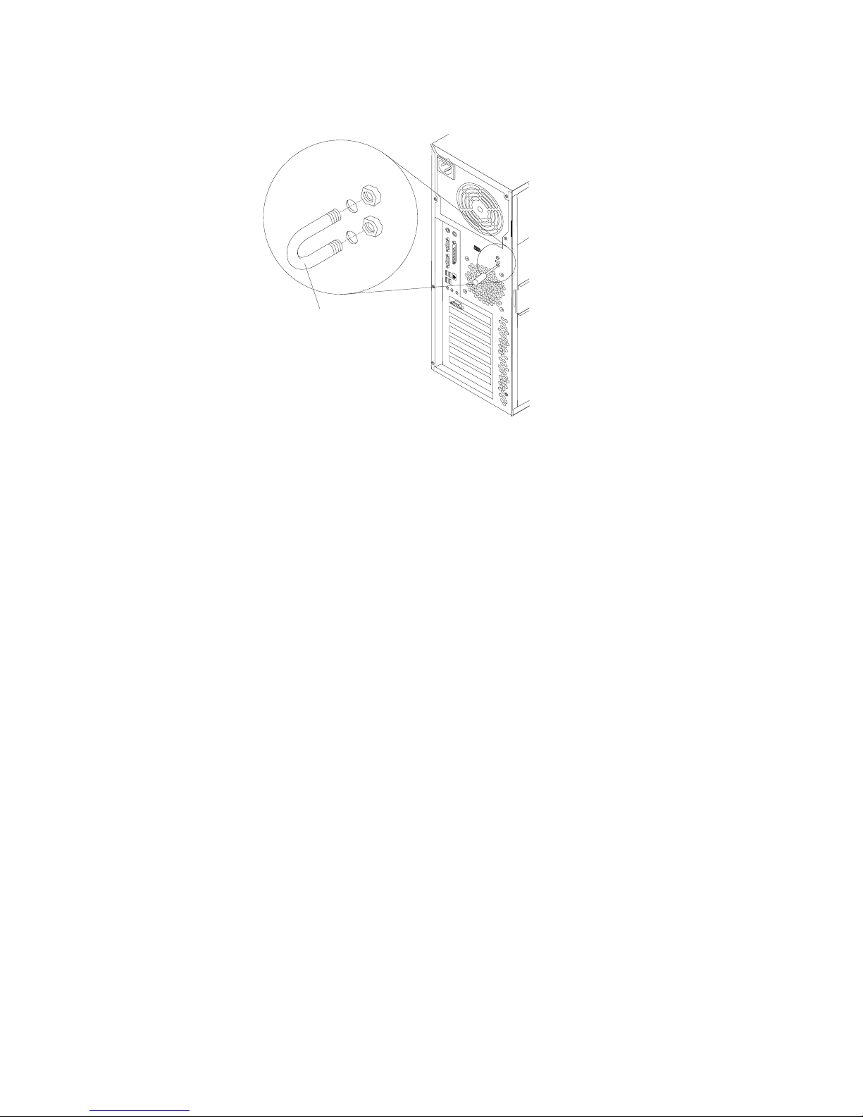
6. If
7.
If
1.
2.
68
cables connected to the computer.
Rope clip
you have other options to install or remove, do so now; otherwise, replace the
side cover (see “Replacing the side cover”).
Reconnect the external cables and power cords. Turn on the attached devices,
and turn on the computer.
Replacing the side cover
you removed the support bracket, reinstall it before you replace the side cover.
See “Removing and installing the support bracket” on page 54.
Note: The rear adapter retaining bracket rests against the computer side cover.
You might find it easier to lay the computer on its side to replace the side
cover.
Complete the following steps to replace the side cover:
Make sure that all cables, adapters, and other components are installed and
seated correctly and that you have removed all work tools or parts from inside
the computer.
Install the side cover by placing it into position on the computer. Be certain that
the lip on the bottom of the cover rests on the ledge on the bottom of the
chassis before rotating the cover up to the verticle position. Press down on the
cover-release latch as you slide the side cover forward to lock the side cover.
IBM IntelliStation M Pro Types 6220 and 6230: User’s Guide
Page 91

4.
1.
2.
on
3.
to
If
v
v
v
4
9
3
1
3.
Reconnect the external cables and power cords to the computer; then, connect
the power cords to electrical outlets.
Turn on the attached devices; then, turn on the computer.
Connecting external options
You can connect a number of optional external devices to the connectors on the
rear and front of the computer.
Complete the following steps to connect an external device:
Read the safety information beginning on page vii, the guidelines in “Handling
static-sensitive devices” on page 29, and the documentation that comes with
your options.
Turn off the computer and all attached devices (see “Turning off the computer”
page 20).
Follow the instructions that come with the option to prepare it for installation and
connect it to the computer.
you are attaching a SCSI device, see “Ultra320 SCSI connector” on page 73 for
SCSI ID and cabling information.
Input/output connectors
Connect optional external devices to the connectors on the front and rear of the
computer.
Your computer has the following input/output (I/O) connectors:
One audio line in
Two audio line out
Two audio microphone
Chapter 4. Installing options
69
Page 92

v
v
v
v
v
v
v
70
v
One Ethernet
Two IEEE 1394 (FireWire) (some models)
One keyboard
One mouse
One parallel
Two serial
Six Universal Serial Bus (USB)
One video
The following illustration shows the locations of the connectors on the M Pro Type
6220.
IEEE 1394
(FireWire) connector
Mouse
Parallel
Ethernet
Line in
Microphone
Keyboard
Serial connectors
USBs
Line out
Video
Power cord connector
The following illustration shows the locations of the connectors on the M Pro Type
6230.
Power cord
connector
1394 IEEE
(FireWire) connector
Mouse
Keyboard
Parallel
Serial
connectors
Ethernet
USBs
USBs
Line out
Line in
Mic
Video
1394
The following sections describe these connectors.
Audio connectors
Use the audio connectors to connect external audio equipment to the computer.
The following illustration shows the audio connectors.
IBM IntelliStation M Pro Types 6220 and 6230: User’s Guide
Page 93

Line out
(green)
Line in
(blue)
Mic
(pink)
Line in
There is one line-in connector on the rear of the computer. The computer receives
audio signals through this connector from an external audio device.
Line out
There are two line-out connectors, one on the front and one on the rear of the
computer. The computer sends audio signals through this connector to powered
speakers with built-in amplifiers, headphones, a multimedia keyboard, or the audio
line-in connector on a stereo system. The internal speaker in the computer is
disabled when a device is attached to this connector.
Mic
There are two microphone connectors, one on the front and one on the rear of the
computer. Connect a microphone to this connector to record sounds onto the hard
disk or to use speech-recognition software. There are two microphone connectors,
one on the front and one on the rear of the computer.
Auxiliary-device (pointing-device) connector
There is one auxiliary-device connector on the rear of the computer. Use this
connector to connect a mouse or other pointing device. The following illustration
shows an auxiliary-device connector.
6
4
2
5
3
1
Ethernet (RJ-45) connector
There is one Ethernet connector on the rear of the computer. Use this connector to
connect the computer to a 10-Mbps, 100-Mbps, or 1000-Mbps network. The
following illustration shows an Ethernet connector.
Activity LED
(green)
8
Connect a Category 3, 4, or 5 unshielded twisted-pair (UTP) cable to this connector.
The 100BASE-TX and 1000BASE-T Fast Ethernet standards require Category 5 or
higher cabling.
The Ethernet connector has one LED that indicates Ethernet-link status. When this
LED is lit, it indicates that there is an active connection on the Ethernet port. Activity
between the computer and the network is indicated by the Ethernet transmit/receive
activity LEDs on the front and rear of the computer (see “Controls and LEDs” on
page 9).
Link LED
(green)
1
Chapter 4. Installing options
71
Page 94

If
72
IEEE 1394 (FireWire) connector (some models)
There is one 4-pin IEEE 1394 (FireWire) connector on the front of the computer and
one 6-pin IEEE 1394 (FireWire) connector on the rear of the computer. Use these
connectors to connect IEEE 1394 (FireWire) devices. The following illustrations
show the IEEE 1394 (FireWire) connectors.
4-pin IEEE 1394 (FireWire) connector (front)
3
4
21
6-pin IEEE 1394 (FireWire) connector (rear)
4
2
6
1
Keyboard connector
There is one keyboard connector on the rear of the computer. Use this connector to
connect a PS/2 (non-USB) keyboard. The following illustration shows a keyboard
connector.
6
4
2
you attach a keyboard to this connector, USB ports and devices are disabled
during the power-on self-test (POST).
Parallel connector
There is one parallel connector on the rear of the computer. Use this connector to
connect a parallel device. The following illustration shows a parallel connector.
13
25
The parallel connector supports three standard Institute of Electrical and Electronics
Engineers (IEEE) 1284 modes of operation: standard parallel port (SPP), enhanced
parallel port (EPP), and extended capability port (ECP). If you configure the parallel
port to operate in bidirectional mode, it supports the ECP and EPP modes. When
the parallel connector is configured as bidirectional, use an IEEE 1284-compliant
cable that does not exceed 3 meters (9.8 ft). Use the Devices and I/O Ports
options in the IBM Configuration/Setup Utility program to configure the parallel
connector as bidirectional.
3
5
5
3
1
1
14
IBM IntelliStation M Pro Types 6220 and 6230: User’s Guide
Page 95

to
v
v
v
v An
on
on
Serial connectors
There are two serial connectors on the rear of the computer. Use these connectors
connect serial devices. The following illustration shows a serial connector.
1
69
Ultra320 SCSI connector
Your computer has an integrated SCSI controller. This single-channel controller
supports an independent, Ultra320 SCSI channel that supports up to 15 SCSI
devices. The SCSI connector for the channel is on the system board. The controller
has the following features:
Double-transition clocking to achieve up to 320 MBps (mgegbytes per second)
data-transfer rates
Domain name validation to negotiate compatible data-transfer speeds with each
device
Cyclic-redundancy checking (CRC) to improve data reliability
active terminator for SCSI bus termination
SCSI cabling requirements
You can install four internal SCSI devices using the SCSI signal cable that comes
with some computer models. If you plan to attach external SCSI devices, you must
order an optional PCI SCSI adapter and external cable. To select and order the
correct cables for use with external devices, contact your IBM marketing
representative or authorized reseller. To receive an indication of SCSI hard-disk
drive activity, you must also connect the SCSI adapter to the SCSI LED connector
the system board. See “System-board internal connectors” on page 52 for the
locations of the SCSI connectors.
5
Setting SCSI IDs
Each SCSI device that is connected to a SCSI controller must have a unique SCSI
ID. This ID enables the SCSI controller to identify the device and ensure that
different devices on the same SCSI channel do not attempt to transfer data
simultaneously. SCSI devices that are connected to different SCSI channels can
have duplicate SCSI IDs. See the information that comes with the device for
instructions for setting its SCSI ID.
Universal Serial Bus connectors
There are six Universal Serial Bus (USB) 2.0 connectors, two on the front and four
the rear of the computer. Use the USB connectors to connect optional telephony
and multimedia devices. USB 2.0 technology transfers data at up to 480 Mb per
second (Mbps) with a maximum of 127 external devices and a maximum signal
distance of 5 meters (16 ft) per segment (if the device that is attached to the
computer is a USB 2.0 device). If multiple USB devices are attached to the
computer, the USB hub must be USB 2.0; otherwise, all USB 2.0 devices will
transfer data at 12 Mbps. Using Plug and Play technology, USB devices are
configured automatically. The following illustration shows a USB connector.
14
Use a 4-pin USB cable to connect an external devices to a USB connector.
Chapter 4. Installing options
73
Page 96

If
74
Video connector
If you connect a PS/2 (non-USB) keyboard to the keyboard connector, USB ports
and devices are disabled during power-on self-test (POST).
you connect a USB keyboard that has a mouse port, the keyboard emulates a
mouse, and you cannot disable the mouse settings in the Configuration/Setup Utility
program.
The Accelerated Graphics Port (AGP) adapter, which is in the AGP slot on the
system board, provides the video connector. This connector is on the rear of the
computer. Use the video connector to connect a monitor or other display. The
following illustrations show examples of different video connectors.
Analog video connector
5
1
1115
Digital (DVI-I) video connector
1
C1 C2
C3C5C4
Low force helical-60 (LFH-60) video connector
Some models come with a digital video interface (DVI) connector for connecting a
digital monitor. If you have problems viewing information with a second monitor, see
“Changing monitor settings” on page 16.
Models with the NVIDIA Quadro4 980XGL, NVIDIA Quadro FX 500, NVIDIA FX
1000, NVIDIA Quadro FX 1100, or NVIDIA Quadro FX 3000 video adapter come
with a DVI-I to VGA style analog converter for each DVI-I connector.
IBM IntelliStation M Pro Types 6220 and 6230: User’s Guide
Page 97

Attention: To get the best performance from the NVIDIA Quardro FX 1000,
NVIDIA Quadro FX 1100, and NVIDIA Quadro FX 3000 video adapters, you must
connect the video adapter to the computer power supply. Otherwise, the video
adapter will be operating with very limited power, resulting in a decrease in
performance for some applications. You will need to use one of the disk drive power
drops to connect the video adapter to the computer power supply. This means that
when you install this video adapter in your computer, you have one less power drop
for optional internal devices. The following illustration shows the location of the
video adapter power connector:
Models with the NVIDIA Quadro NVS 280 or NVIDIA Quadro4 580XGL video
adapter come with a low force helical-60 (LFH-60) to dual-analog monitor pigtail
cable. If you want to set up two digital monitors, you will need to purchase a
separate dual-digital monitor cable.
Chapter 4. Installing options
75
Page 98

76
IBM IntelliStation M Pro Types 6220 and 6230: User’s Guide
Page 99

If
v
v
v
of
v
v
An
by
©
Chapter 5. Solving problems
This section provides basic troubleshooting information to help you diagnose and
solve some problems that might occur.
you cannot locate and correct the problem using the information in this chapter,
see Appendix A, “Getting help and technical assistance,” on page 109 for more
information.
Diagnostic tools overview
The following tools are available to help you identify and solve hardware-related
problems:
Computer Support flowchart
The Computer Support flowchart on the following page will help you determine
how to access help from IBM and register your computer.
POST beep codes and error messages
The power-on self-test generates beep codes and messages to indicate
successful test completion or the detection of a problem. See “Power-on self-test
(POST)” on page 79 for more information. Additional information is recorded in
the system error logs. (For detailed information, see Error Logs under
“Configuration/Setup Utility menu choices” on page 24.
Diagnostic programs
The system diagnostic programs are on a hidden partition on your computer hard
disk. These programs are the primary methods of testing the major components
your computer. See “Diagnostic programs and error messages” on page 85 for
more information.
Troubleshooting charts
This charts lists problem symptoms and steps to correct each problem. See the
“Troubleshooting charts” on page 94 for more information.
System-board error LEDs
LED on the system board might also be lit to help isolate an error indicated
the system error LED on the front of the computer. See the “System-board
error LEDs” on page 100 for more information.
Copyright IBM Corp. 2004
77
Page 100

Computer Support
Computer working
properly?
Ye s
No
Check all cables for loose connections
and verify that all optional devices you
installed are on the compatibility matrix.
You can view the atcompatibility matrix
http://www.pc.ibm.com/us/compat/
intellistation/
Problem
solved?
Ye s
No
Use the troubleshooting
information provided with
your computer to determine
the cause of the problem
and the action to take.
Register your computer. Go to
http://www.ibm.com/pc/register/
View information about IBM Support
Line at
http://www.ibm.com/services/sl/products/
or view support telephone numbers at
http://www.ibm.com/planetwide/
View support telephone numbers at
http://www.ibm.com/planetwide/
Problem
solved?
Ye s
No
Flash the latest levels of BIOS,
and download the latest level of
diagnostics. You can download
this code at
http://www.ibm.com/pc/support/
78
IBM IntelliStation M Pro Types 6220 and 6230: User’s Guide
Ye s
Problem
solved?
No
Hardware
Software
Hardware
or Software
problem?
 Loading...