

IBM IntelliStation M Pro 6225, IntelliStation M Pro 6228, IntelliStation M Pro Type 6225, IntelliStation M Pro Type 6228 Hardware Maintenance Manual And Troubleshooting Manual
Page 1

IntelliStation M Pro Types 6225 and 6228
Hardware Maintenance Manual and Troubleshooting
Guide
Page 2

Page 3

IntelliStation M Pro Types 6225 and 6228
Hardware Maintenance Manual and Troubleshooting
Guide
Page 4

Notes
v Before using this information and the product it supports, read the general information in
Appendix B, “Safety information,” on page 115, and Appendix C, “Notices,” on page 149.
v The most recent version of this document is available at http://www.ibm.com/pc/support/.
Third Edition (June 2008)
© Copyright International Business Machines Corporation 2004. All rights reserved.
US Government Users Restricted Rights – Use, duplication or disclosure restricted by GSA ADP Schedule Contract
with IBM Corp.
Page 5

About this document
This document contains basic configuration information, diagnostic information, error
codes, error messages, service information, and a symptom-to-FRU index for the
IBM® IntelliStation® M Pro Type 6225 and 6228 computers.
Important: The field replaceable unit (FRU) procedures in this document are
intended for trained servicers who are familiar with IBM products.
Customer replacement units (CRUs) can be replaced by the customer.
See Chapter 7, “Parts listing, IntelliStation M Pro Types 6225 and
6228,” on page 105, to determine if the component being replaced is a
FRU or a CRU. Before servicing an IBM product, be sure to read
Appendix B, “Safety information,” on page 115.
Important safety information
Be sure to read all caution and danger statements in this book before performing
any of the instructions.
Leia todas as instruções de cuidado e perigo antes de executar qualquer operação.
Prenez connaissance de toutes les consignes de type Attention et
Danger avant de procéder aux opérations décrites par les instructions.
Lesen Sie alle Sicherheitshinweise, bevor Sie eine Anweisung ausführen.
Accertarsi di leggere tutti gli avvisi di attenzione e di pericolo prima di effettuare
qualsiasi operazione.
Lea atentamente todas las declaraciones de precaución y peligro ante de llevar a
cabo cualquier operación.
WARNING: Handling the cord on this product or cords associated with accessories
sold with this product, will expose you to lead, a chemical known to the State of
California to cause cancer, and birth defects or other reproductive harm. Wash
hands after handling.
ADVERTENCIA: El contacto con el cable de este producto o con cables de
accesorios que se venden junto con este producto, pueden exponerle al plomo, un
elemento químico que en el estado de California de los Estados Unidos está
considerado como un causante de cancer y de defectos congénitos, además de
otros riesgos reproductivos. Lávese las manos después de usar el producto.
© Copyright IBM Corp. 2004 iii
Page 6

Online support
You can download the most current diagnostic, BIOS flash, and device-driver files
from http://www.ibm.com/pc/support/.
iv IntelliStation M Pro Types 6225 and 6228: Hardware Maintenance Manual and Troubleshooting Guide
Page 7

Contents
About this document . . . . . . . . . . . . . . . . . . . . . . iii
Important safety information . . . . . . . . . . . . . . . . . . . . iii
Online support . . . . . . . . . . . . . . . . . . . . . . . . .iv
Chapter 1. Introduction . . . . . . . . . . . . . . . . . . . . . .1
Related documentation . . . . . . . . . . . . . . . . . . . . . .1
Notices and statements used in this document . . . . . . . . . . . . . .2
Features and specifications . . . . . . . . . . . . . . . . . . . . .3
Server controls, connectors, and LEDs . . . . . . . . . . . . . . . .4
Server power features . . . . . . . . . . . . . . . . . . . . . . .5
Turning on the computer . . . . . . . . . . . . . . . . . . . . .5
Turning off the computer . . . . . . . . . . . . . . . . . . . . .6
Chapter 2. Configuring the computer . . . . . . . . . . . . . . . .7
Configuration programs and capabilities . . . . . . . . . . . . . . . .7
Starting the Configuration/Setup Utility program . . . . . . . . . . . . .8
Chapter 3. Diagnostics . . . . . . . . . . . . . . . . . . . . . .9
General checkout . . . . . . . . . . . . . . . . . . . . . . . .9
Diagnostic tools overview . . . . . . . . . . . . . . . . . . . . .10
POST error log . . . . . . . . . . . . . . . . . . . . . . . . .11
POST beep codes . . . . . . . . . . . . . . . . . . . . . . . .11
Small computer system interface (SCSI) messages (some models) . . . . . .11
Diagnostic programs and error messages . . . . . . . . . . . . . . .12
Text messages . . . . . . . . . . . . . . . . . . . . . . . .12
Starting the diagnostic programs and viewing the test log . . . . . . . .13
PC-Doctor for Windows . . . . . . . . . . . . . . . . . . . . . .15
Error symptoms . . . . . . . . . . . . . . . . . . . . . . . .15
Recovering your operating system and preinstalled software . . . . . . . .15
Recovering the operating system . . . . . . . . . . . . . . . . .15
Recovering or installing device drivers . . . . . . . . . . . . . . .16
Creating and using an IBM Enhanced Diagnostics diskette . . . . . . . . .17
Creating an IBM Enhanced Diagnostics diskette . . . . . . . . . . . .17
Using the IBM Enhanced Diagnostics diskette . . . . . . . . . . . .18
Creating an emergency recovery-repair diskette . . . . . . . . . . . . .18
Creating an emergency recovery-repair diskette in Windows . . . . . . .19
Creating an emergency recovery-repair diskette in Red Hat Linux . . . . .19
Using the recovery-repair diskette . . . . . . . . . . . . . . . . . .20
Erasing a lost or forgotten password (clearing CMOS) . . . . . . . . . .20
Updating BIOS code . . . . . . . . . . . . . . . . . . . . . . .22
Recovering from a POST/BIOS update failure . . . . . . . . . . . . .23
Clearing hardware option conflicts and saving option ROM space . . . . . .24
Power checkout . . . . . . . . . . . . . . . . . . . . . . . .25
Troubleshooting the Ethernet controller . . . . . . . . . . . . . . . .26
Network connection problems . . . . . . . . . . . . . . . . . .26
Ethernet controller troubleshooting chart . . . . . . . . . . . . . .27
Chapter 4. Customer replacement units . . . . . . . . . . . . . . .29
Installation guidelines . . . . . . . . . . . . . . . . . . . . . .29
System reliability guidelines . . . . . . . . . . . . . . . . . . .29
Handling static-sensitive devices . . . . . . . . . . . . . . . . .29
Major components of the IntelliStation M Pro Types 6225 and 6228 . . . . .31
Side cover . . . . . . . . . . . . . . . . . . . . . . . . . .32
© Copyright IBM Corp. 2004 v
Page 8

Removing the side cover . . . . . . . . . . . . . . . . . . . .32
Replacing the side cover . . . . . . . . . . . . . . . . . . . .33
Removing and Installing the Bezel . . . . . . . . . . . . . . . . . .34
Removing and replacing the microprocessor fan assembly . . . . . . . . .35
Removing and replacing the SCSI daughter card . . . . . . . . . . . .37
Installing an adapter . . . . . . . . . . . . . . . . . . . . . . .39
Cabling an optional SCSI adapter . . . . . . . . . . . . . . . . . .43
Removing and replacing the front I/O panel . . . . . . . . . . . . . .44
Removing and replacing the CD-ROM or CD-RW drive . . . . . . . . . .45
Installing a drive . . . . . . . . . . . . . . . . . . . . . . . .47
Installing a drive in bay 2, 3, or 4 . . . . . . . . . . . . . . . . .48
Installing a hard disk drive in bay 5 . . . . . . . . . . . . . . . .50
Power and signal cables for internal drives . . . . . . . . . . . . .53
Installing memory modules . . . . . . . . . . . . . . . . . . . .54
Removing and replacing the internal speaker . . . . . . . . . . . . . .56
Replacing the battery . . . . . . . . . . . . . . . . . . . . . .57
Installing a security cable . . . . . . . . . . . . . . . . . . . . .59
Connecting external options . . . . . . . . . . . . . . . . . . . .60
Input/output connectors . . . . . . . . . . . . . . . . . . . . . .61
Audio connectors . . . . . . . . . . . . . . . . . . . . . . .62
Auxiliary-device (pointing-device) connector . . . . . . . . . . . . .62
Ethernet (RJ-45) connector . . . . . . . . . . . . . . . . . . .62
IEEE 1394 (FireWire) connector (some models) . . . . . . . . . . . .63
Keyboard connector . . . . . . . . . . . . . . . . . . . . . .63
Parallel connector . . . . . . . . . . . . . . . . . . . . . . .63
Serial connectors . . . . . . . . . . . . . . . . . . . . . . .64
Ultra320 SCSI connector . . . . . . . . . . . . . . . . . . . .64
Universal Serial Bus connectors . . . . . . . . . . . . . . . . .65
Video connector . . . . . . . . . . . . . . . . . . . . . . .65
Chapter 5. Field replaceable units . . . . . . . . . . . . . . . . .67
Microprocessor and heat sink . . . . . . . . . . . . . . . . . . .68
Rotating the internal drive cage . . . . . . . . . . . . . . . . . . .73
Power supply . . . . . . . . . . . . . . . . . . . . . . . . .74
Power switch/LED assembly . . . . . . . . . . . . . . . . . . . .76
System board . . . . . . . . . . . . . . . . . . . . . . . . .77
System board option connectors . . . . . . . . . . . . . . . . .77
System board internal connectors . . . . . . . . . . . . . . . . .78
System board external connectors . . . . . . . . . . . . . . . . .79
System board error LEDs . . . . . . . . . . . . . . . . . . . .79
System board jumpers . . . . . . . . . . . . . . . . . . . . .80
Removing the system board . . . . . . . . . . . . . . . . . . .81
Chapter 6. Symptom-to-FRU index . . . . . . . . . . . . . . . . .83
Beep symptoms . . . . . . . . . . . . . . . . . . . . . . . .83
No-beep symptoms . . . . . . . . . . . . . . . . . . . . . . .85
Diagnostic error codes . . . . . . . . . . . . . . . . . . . . . .85
Error symptoms . . . . . . . . . . . . . . . . . . . . . . . .87
POST error codes . . . . . . . . . . . . . . . . . . . . . . . .95
SCSI error codes . . . . . . . . . . . . . . . . . . . . . . . .98
Temperature error messages . . . . . . . . . . . . . . . . . . . .98
Fan error messages . . . . . . . . . . . . . . . . . . . . . . .99
Power error messages . . . . . . . . . . . . . . . . . . . . . .99
System shutdown . . . . . . . . . . . . . . . . . . . . . . . 100
Voltage related system shutdown . . . . . . . . . . . . . . . . . 100
Temperature related system shutdown . . . . . . . . . . . . . . . 100
vi IntelliStation M Pro Types 6225 and 6228: Hardware Maintenance Manual and Troubleshooting Guide
Page 9

Hard disk drive checkout . . . . . . . . . . . . . . . . . . . . . 101
Host built-in self-test (BIST) . . . . . . . . . . . . . . . . . . . . 101
Bus fault messages . . . . . . . . . . . . . . . . . . . . . . . 101
Undetermined problems . . . . . . . . . . . . . . . . . . . . . 102
Problem determination tips . . . . . . . . . . . . . . . . . . . . 103
Chapter 7. Parts listing, IntelliStation M Pro Types 6225 and 6228 . . . . 105
System . . . . . . . . . . . . . . . . . . . . . . . . . . . 106
System replaceable units . . . . . . . . . . . . . . . . . . . . . 107
Recovery CD, Type 6225 and 6228 . . . . . . . . . . . . . . . . .110
Keyboards (CRUs) . . . . . . . . . . . . . . . . . . . . . . .110
Power cords (CRUs) . . . . . . . . . . . . . . . . . . . . . . 111
Appendix A. Getting help and technical assistance . . . . . . . . . .113
Before you call . . . . . . . . . . . . . . . . . . . . . . . .113
Using the documentation . . . . . . . . . . . . . . . . . . . . .113
Getting help and information from the World Wide Web . . . . . . . . .114
Software service and support . . . . . . . . . . . . . . . . . . .114
Hardware service and support . . . . . . . . . . . . . . . . . . .114
Appendix B. Safety information . . . . . . . . . . . . . . . . .115
General safety . . . . . . . . . . . . . . . . . . . . . . . . .115
Electrical safety . . . . . . . . . . . . . . . . . . . . . . . .116
Safety inspection guide . . . . . . . . . . . . . . . . . . . . .117
Handling electrostatic discharge-sensitive devices . . . . . . . . . . .118
Grounding requirements . . . . . . . . . . . . . . . . . . . . .118
Safety notices (multilingual translations) . . . . . . . . . . . . . . .119
Appendix C. Notices . . . . . . . . . . . . . . . . . . . . . . 149
Edition notice . . . . . . . . . . . . . . . . . . . . . . . . . 149
Trademarks . . . . . . . . . . . . . . . . . . . . . . . . . . 150
Important notes . . . . . . . . . . . . . . . . . . . . . . . . 151
Product recycling and disposal . . . . . . . . . . . . . . . . . . 151
Battery return program . . . . . . . . . . . . . . . . . . . . . 152
Monitor . . . . . . . . . . . . . . . . . . . . . . . . . . . 153
Electronic emission notices . . . . . . . . . . . . . . . . . . . . 153
Federal Communications Commission (FCC) statement . . . . . . . . 153
Industry Canada Class B emission compliance statement . . . . . . . . 154
Avis de conformité à la réglementation d’Industrie Canada . . . . . . . 154
European Union EMC Directive conformance statement . . . . . . . . 154
Japanese Voluntary Control Council for Interference (VCCI) statement 155
Power cords . . . . . . . . . . . . . . . . . . . . . . . . . 156
Index . . . . . . . . . . . . . . . . . . . . . . . . . . . . 159
Contents vii
Page 10

viii IntelliStation M Pro Types 6225 and 6228: Hardware Maintenance Manual and Troubleshooting Guide
Page 11

Chapter 1. Introduction
This document contains basic configuration information, diagnostic information, error
codes, error messages, service information, and a symptom-to-FRU index for the
IBM IntelliStation M Pro Types 6225 and 6228.
You can obtain up-to-date information about the computer and other IBM computer
products at http://www.ibm.com/pc/us/intellistation/.
Note: The illustrations in this document might differ slightly from your hardware.
Model number
and serial number
Related documentation
This Hardware Maintenance Manual and Troubleshooting Guide is provided in
Portable Document Format (PDF). It contains information to help a user solve
problems or to provide helpful information to a service technician. The following
documents also come with the computer:
v User’s Guide
This document is in PDF on the IBM IntelliStation® Documentation CD. It
contains general information about the computer.
v Installation Guide
This printed document contains instructions for setting up the computer and basic
instructions for installing some options.
v Safety Information
This document is in PDF on the IBM IntelliStation Documentation CD. It contains
translated caution and danger statements. Each caution and danger statement
that appears in the documentation has a number that you can use to locate the
corresponding statement in your language in the Safety Information document.
v Adaptec SCSI documentation
This document is in PDF on the Device Drivers CD. It contains information and
instructions for installing and configuring small computer system interface (SCSI)
device drivers and devices.
© Copyright IBM Corp. 2004 1
Page 12

v Readme files on the Device Drivers CD
Several readme files on this CD contain information about the preinstalled device
drivers. Other readme files on this CD contain information about the various
adapters and devices that might be installed in or attached to your computer.
Depending
on the computer model, additional documentation might be included on
the IBM IntelliStation Documentation CD.
The computer might have features that are not described in the documentation that
was received with the computer. The documentation might be updated occasionally
to include information about those features, or technical updates might be available
to provide additional information that is not included in the computer documentation.
These updates are available from the IBM Web site at http://www.ibm.com/pc/
support/.
Notices and statements used in this document
The caution and danger statements used in this document are also in the
multilingual Safety Information document, which is on the IBM IntelliStation
Documentation CD. Each statement is numbered for reference to the corresponding
statement in the Safety Information document.
The following notices and statements are used in this document:
v Notes: These notices provide important tips, guidance, or advice.
v Important: These notices provide information or advice that might help you avoid
inconvenient or problem situations.
v Attention: These notices indicate potential damage to programs, devices, or
data. An attention notice is placed just before the instruction or situation in which
damage could occur.
v Caution: These statements indicate situations that can be potentially hazardous
to you. A caution statement is placed just before the description of a potentially
hazardous procedure step or situation.
v Danger: These statements indicate situations that can be potentially lethal or
extremely hazardous to you. A danger statement is placed just before the
description of a potentially lethal or extremely hazardous procedure step or
situation.
2 IntelliStation M Pro Types 6225 and 6228: Hardware Maintenance Manual and Troubleshooting Guide
Page 13

Features and specifications
The following information is a summary of the features and specifications of the
computer. Depending on the computer model, some features might not be available,
or some specifications might not apply.
Table 1. Features and specifications
Microprocessor:
v Intel™ Pentium 4 processor
v 1 MB Level-2 cache
v 800 MHz front-side bus (FSB)
Memory:
v Minimum: 512 MB
v Maximum: 4 GB
v Type: PC2-3200
v Connectors: four dual inline memory
module (DIMM) connectors
drives:
Internal
v Diskette: 1.44 MB (two mode)
(optional)
v Hard disk drive: SATA or SCSI
v One of the following drives:
– CD-ROM: IDE
– DVD/CD-RW combo: IDE
– CD-RW: IDE
Expansion
bays:
v One slim-high 3.5-inch drive bays
(one hard disk drive installed in some
models)
v Two half-high 5.25-inch bays (optical
drive installed in one bay)
v Two slim-high 3.5-inch bays
expansion slots:
PCI
v One PCI Express x1 slot
v One PCI Express x16 slot
v Two 33 MHz/32-bit PCI slots
supply:
Power
One 400 watts (115-230 V ac)
Cooling:
One speed-controlled fan
Integrated functions:
v Broadcom 5721 10/100/1000 Ethernet
controller with RJ-45 Ethernet connector
v Single-channel Ultra320 SCSI provided
by a mini-PCI card
v Two serial connectors
v One parallel connector
v Four-port serial ATA controller
v Two IEEE 1394 (FireWire) ports
(four-pin on front, six-pin on rear)
v Eight Universal Serial Bus (USB)
connectors (two on front and six on
rear)
v Keyboard connector
v Mouse connector
v Audio connectors
– Line out (front and rear)
– Mic (front)
– Line in (rear)
v Single-channel IDE controller
adapter: (depending on your
Video
model)
v NVIDIA Quadro NVS 280 (DMS-59),
PCI Express x16, with 64 MB DDR
synchronous dynamic random access
memory (SDRAM) video memory and
dual analog connectors (or dual digital
monitor capability with the purchase of
an additional pigtail cable)
v NVIDIA Quadro FX 1300 (DVI-I), PCI
Express x16, with 128 MB DDR
SDRAM video memory with dual DVI-I
connectors
v NVIDIA Quadro FX 3400 (DVI-I), PCI
Express x16, with 256 MB GDDR3
SDRAM video memory with dual DVI-I
connectors
v ATI FireGL V3100 (DVI-I & VGA), PCI
Express x16, with 128 MB DDR
SDRAM video memory with one DVI-I
connector and one VGA connector
Electrical input:
v Sine-wave input (50 or 60 Hz) required
v Input voltage and frequency ranges
automatically selected
v Input voltage low range:
– Minimum: 90 V ac
– Maximum: 137 V ac
v Input voltage high range:
– Minimum: 180 V ac
– Maximum: 265 V ac
v Input kilovolt-amperes (kVA) approximately:
– Minimum: 0.12 kVA
– Maximum: 0.58 kVA
output:
Heat
Approximate heat output in British thermal
units (Btu) per hour
v Minimum configuration: 375 Btu (110 watts)
v Maximum configuration: 1936 Btu (568
watts)
Environment:
v Air temperature:
– Computer on: 10° to 35°C (50° to 95°F)
Altitude: 0 to 2134 m (7000 ft)
– Computer off: -40° to +60°C (-40° to
+140°F)
Maximum altitude: 2133 m (7000 ft)
v Humidity (operating and storage): 8% to
80%
Acoustical noise emissions:
v Sound power, idle: 4.5 bel
v Sound power, operating: 4.9 bel
Size:
v Height: 492 mm (19.4 in.)
v Depth: 450 mm (17.7 in.)
v Width: 175 mm (6.9 in.)
v Weight: 10.5 kg (23 lb) to 13.5 kg (30 lb)
depending upon configuration
Note: Power consumption and heat output vary depending on the number and type
of optional features installed and the power-management optional features in
use.
Chapter 1. Introduction 3
Page 14

Server controls, connectors, and LEDs
This section identifies the controls, light-emitting diodes (LEDs), and front
connectors on IntelliStation M Pro Types 6225 and 6228. See “Input/output
connectors” on page 61 for an illustration of the connectors on the rear of the
computer..
Power-control button
Power-on LED
Ethernet
activity LED
System error LED
Hard disk drive
activity LED
CD-ROM drive activity LED
CD-eject button
AC power LED
Power supply
error LED
Diskette drive activity
LED (optional)
Diskette-eject
button (optional)
1
3
9
4
IEEE 1394 (Firewire)
connector
USB connector
USB connector
Microphone connector
Line out connector
CD-ROM drive activity LED
When this LED is lit, it indicates that the CD-ROM drive is in use.
CD-eject button
Press this button to insert a CD into or remove a CD from the CD-ROM
drive.
AC power LED
When this green LED is lit, it indicates that the computer is connected to an
ac power source. This LED is on the rear of the computer.
Power supply error LED
When this amber LED is lit, it indicates that a power supply error has
occurred. This LED is on the rear of the computer.
Diskette drive activity LED
When this LED is lit, it indicates that the diskette drive is in use.
Diskette-eject button
Press this button to release a diskette from the diskette drive.
IEEE 1394 (FireWire) connectors
Use these connectors (four-pin on the front and six-pin on the rear) to
connect FireWire devices, such as digital video cameras and external hard
disk drives.
4 IntelliStation M Pro Types 6225 and 6228: Hardware Maintenance Manual and Troubleshooting Guide
Page 15

USB connectors
Use these connectors to connect USB devices to your computer, using
redundant Plug and Play technology.
Microphone connector (pink)
Use this connector to connect a microphone to your computer when you
want to record voices or other sounds on the hard disk. Yo u can also use
this connector (and a microphone) with speech-recognition software.
Line out connector (green)
Use this connector to send audio signals from the computer to external
devices, such as speakers with built-in amplifiers, headphones, multimedia
keyboards, or the audio line-in jack on a stereo system.
System-error LED
When this LED is lit, it indicates that a system error has occurred. An LED
on the system board might also be lit to help isolate the error. If the system
board LED is not lit, check the error log.
Hard disk drive activity LED
When this LED is lit, it indicates that the hard disk drive is in use.
Ethernet activity LED
When this LED is lit, it indicates that there is activity between the computer
and the network. There are two of these LEDs, one on the front and one on
the rear of the computer.
Power-on LED
When this LED is lit, it indicates that the computer is turned on.
Power-control button
Press this button to turn the computer on or off.
Ethernet link status LED
When this LED is flickering, it indicates that there is an active connection on
the Ethernet connector. This LED is on the rear of the computer.
Server power features
When the computer is connected to an ac power source but is not turned on, the
operating system does not run, and all core logic is shut down; however, the
computer can respond to remote requests to turn on the computer. When the
computer is connected to an ac power source but is not turned on, the power-on
LED on the front of the computer is not lit and the ac power LED on the rear of the
computer is lit.
Notes:
1. Turn on all external devices, such as the monitor, before turning on the
computer.
2. The power-on LED on the front of the computer is lit when the computer is on
and while it is being turned on.
Turning on the computer
Approximately 20 seconds after the computer is connected to ac power, the
power-control button becomes active, and you can turn on the computer and start
the operating system by pressing the power-control button.
Chapter 1. Introduction 5
Page 16

The computer can also be turned on in any of the following ways:
v If a power failure occurs while the computer is turned on, the computer will
restart automatically when power is restored.
v When you connect your computer to power for the first time, the Wake on LAN
feature can turn on the computer. If your computer was previously turned on, it
must be properly turned off for the Wake on LAN feature to turn on the computer.
Turning off the computer
When you turn off the computer and leave it connected to ac power, the computer
can respond to remote requests to turn on the computer. To remove all power from
the computer, you must disconnect it from the power source.
Some operating systems require an orderly shutdown before you turn off the
computer. See the operating-system documentation for information about shutting
down the operating system.
®
Statement 5
CAUTION:
The power control button on the device and the power switch on the power supply do
not turn off the electrical current supplied to the device. The device also might have
more than one power cord. To remove all electrical current from the device, ensure
that all power cords are disconnected from the power source.
1 2
The computer can be turned off in any of the following ways:
v You can turn off your computer from the operating system. If this feature is
supported by your operating system, it will turn off the computer after performing
an orderly shutdown of the operating system.
– To turn off the computer from the Microsoft® Windows® XP operating system,
click Start > Turn Off Computer; then, click Turn Off.
– To turn off the computer from the Red Hat Linux operating system, click Red
Hat Linux Main Menu Button > Logout > Shutdown; then, click Yes.
You can press the power-control button on the front of the computer to start an
v
orderly shutdown of the operating system and turn off the computer, if your
operating system supports this feature.
Note: After turning off the computer, wait at least 5 seconds before you press
the power-control button to turn on the computer again.
v You can press and hold the power-control button for more than 4 seconds to
cause an immediate shutdown of the computer. You can use this feature to turn
off the computer if the operating system stops functioning.
6 IntelliStation M Pro Types 6225 and 6228: Hardware Maintenance Manual and Troubleshooting Guide
Page 17

Chapter 2. Configuring the computer
Detailed information about configuring the computer is in the IBM IntelliStation
User’s Guide on the IBM IntelliStationDocumentation CD.
The latest information about these programs and the most recent device-driver files
are available at http://www.ibm.com/pc/support.
Configuration programs and capabilities
The following configuration programs and capabilities come with the computer:
v Configuration/Setup Utility program
The Configuration/Setup Utility program is part of the basic input/output system
(BIOS) code in your computer. You can use this program to configure serial port
assignments, change interrupt request (IRQ) settings, change the device startup
sequence, set the date and time, set passwords, and set the chassis-intrusion
detector.
v Boot Menu program
Boot Menu program is part of the BIOS code in your computer. Use it to
temporarily assign a device to be first in the startup sequence, overriding the
startup sequence that is set in the Configuration/Setup Utility program.
v Broadcom NetXtreme Gigabit Ethernet Boot Agent
The Broadcom NetXtreme Gigabit Ethernet Boot Agent is part of the BIOS code
in your computer. You can use it to configure the network as a startable device,
and you can customize where the network startup option appears in your startup
sequence. Yo u enable and disable the Broadcom NetXtreme Gigabit Ethernet
Boot Agent from the Configuration/Setup Utility program.
v Ethernet controller configuration
The Ethernet controller is integrated on the system board. Yo u do not need to set
any jumpers or configure the controller. However, you must install a device driver
to enable the operating system to address the controller. For device drivers and
information about configuring your Gigabit Ethernet controller, go to
http://www.ibm.com/pc/support/.
v SCSISelect Utility program (some models)
If your computer comes with a SCSI adapter, you can use the SCSISelect Utility
program to configure devices that are attached to the SCSI adapter. Use this
program to change default values, resolve configuration conflicts, and perform a
low-level format on a SCSI hard disk drive.
© Copyright IBM Corp. 2004 7
Page 18

Starting the Configuration/Setup Utility program
Complete the following steps to start the Configuration/Setup Utility program:
1. Turn on the computer and watch the monitor screen. If your computer is already
on when you start this procedure, you must shut down the operating system,
turn off the computer, wait a few seconds until all in-use LEDs go off, and
restart the computer.
2. When the message Press F1 for Configuration/Setup, Press F12 for Boot
Menu appears on the screen during startup, press F1. (This prompt appears on
the screen for only a few seconds. Yo u must press F1 quickly.) If you have set
both a user password and an administrator password, you must type the
administrator password to access the full Configuration/Setup Utility menu.
3. Follow the instructions on the screen.
8 IntelliStation M Pro Types 6225 and 6228: Hardware Maintenance Manual and Troubleshooting Guide
Page 19

Chapter 3. Diagnostics
This section provides basic troubleshooting information to help you solve some
problems that might occur.
General checkout
Follow the checkout procedure for diagnosing hardware problems. Review the
following information before performing the checkout procedure:
v Read Appendix B, “Safety information,” on page 115.
v The system diagnostic programs are stored on a hidden partition on the
computer hard disk. These programs are the primary method of testing the major
components of the computer: the system board, Ethernet controller, video
controller, RAM, keyboard, mouse (pointing device), serial ports, hard disk drives,
and parallel port. Yo u can also use them to test some external devices. If you are
not sure whether a problem is caused by the hardware or by the software, you
can use the diagnostic programs to confirm that the hardware is working
correctly.
v When you run the diagnostic programs, a single problem might cause several
error messages. If you receive several error messages, correct the cause of the
first error message. The other error messages might not occur the next time you
run the diagnostic programs.
v Before running the diagnostic programs, you must determine whether the failing
computer is part of a shared hard disk drive cluster (two or more computers
sharing external storage devices). If you suspect that it is part of a cluster, you
can run all diagnostic programs except the ones that test the storage unit (that is,
a hard disk drive in the storage unit) or the storage adapter that is attached to
the storage unit. The failing computer might be part of a cluster if any of the
following conditions is true:
– The customer identifies the failing computer as part of a cluster.
– One or more external storage units are attached to the failing computer and at
least one of the attached storage units is also attached to another computer
or unidentifiable device.
– One or more computers are located near the failing computer.
v Important:
1. For computers that are part of a shared hard disk drive cluster, run one test
at a time. Do not run any suite of tests, such as “quick” or “normal” tests,
because this could enable the hard disk drive diagnostic tests.
2. If more than one error code is displayed, correct the first error. The other
error codes might not occur the next time you run the diagnostic programs.
3. If the computer is suspended and a POST error code is displayed, see
“POST error codes” on page 95.
4. If the computer is suspended and no error message is displayed, see “Error
symptoms” on page 87 and “Undetermined problems” on page 102.
5. For information about power-supply problems, see “Power checkout” on page
25.
6. For intermittent problems, check the error log; see “Diagnostic programs and
error messages” on page 12.
© Copyright IBM Corp. 2004 9
Page 20

Complete the following steps to perform the checkout procedure:
001 IS THE COMPUTER PART OF A CLUSTER?
YES. Schedule maintenance for the computer. Shut down all computers
related to the cluster. Run the storage test.
NO. Go to step 002.
002 IF THE COMPUTER IS NOT PART OF A CLUSTER:
1. Check the system board LEDs (see “System board error LEDs” on page
79).
2. Turn off the computer and all external devices.
3. Check all cables and power cords.
4. Set all display controls to the middle position.
5. Turn on all external devices.
6. Turn on the computer.
7. Watch the screen for POST errors, and record any POST error
messages that are displayed on the screen. If an error is displayed, look
up the first error (see “POST error codes” on page 95).
8. Run the diagnostic programs (see “Starting the diagnostic programs and
viewing the test log” on page 13).
003 DID THE DIAGNOSTIC PROGRAMS START ?
NO. Find the failure symptom in “Error symptoms” on page 87.
YES. Run the diagnostic programs (see “Starting the diagnostic programs
and viewing the test log” on page 13).
If you receive an error, see Chapter 6, “Symptom-to-FRU index,” on page
83.
If the diagnostics were completed successfully and you still suspect a
problem, see “Undetermined problems” on page 102.
If the computer does not turn on, see “Error symptoms” on page 87.
Diagnostic tools overview
The following tools are available to help you diagnose and solve hardware-related
problems:
v POST beep codes and error messages
The power-on self-test generates beep codes and messages to indicate
successful test completion or the detection of a problem. See “POST error log”
on page 11 for more information.
v Diagnostic programs
The system diagnostic programs are on a hidden partition on the hard disk.
These programs are the primary methods of testing the major components of the
computer. See “Diagnostic programs and error messages” on page 12 for more
information.
v Error charts
These charts list problem symptoms and steps to correct the problem. See “Error
symptoms” on page 15 for more information.
v System-board error LEDs
An LED on the system board might also be lit to help isolate an error that is
indicated by the system error LED on the front of the computer. See the “System
board error LEDs” on page 79 for more information.
10 IntelliStation M Pro Types 6225 and 6228: Hardware Maintenance Manual and Troubleshooting Guide
Page 21

POST error log
When you turn on the computer, the power on self-test (POST) performs a series of
tests to check the operation of system components and some of the installed
options.
If POST finishes without detecting any problems, the first window of the operating
system opens or an application program starts.
If POST detects a problem, more than one beep or no beep might sound, and an
error message appears on the screen.
The POST error log contains the three most recent error codes and messages that
the system generated during POST.
Notes:
1. If you have a user password set, you must type the password and press Enter,
when prompted, before the operating system will start.
2. A single problem might cause several error messages. When this occurs, work
to correct the cause of the first error message. After you correct the cause of
the first error message, the other error messages usually will be resolved the
next time you run the test.
POST beep codes
POST generates beep codes to indicate successful completion or the detection of a
problem.
v One short beep indicates the successful completion of POST.
v More than one beep or no beep indicates that POST detected a problem. For
more information, see “Beep symptoms” on page 83.
If POST detects a problem (more than one beep sounds), an error message
appears on the screen. See “Beep symptoms” on page 83 and “POST error codes”
on page 95 for more information.
Small computer system interface (SCSI) messages (some models)
If the computer has an Ultra320 SCSI adapter installed and you receive a SCSI
error message, see “SCSI error codes” on page 98.
Note: If the computer does not have a SCSI hard disk drive, ignore any message
that indicates that the BIOS code is not installed.
Chapter 3. Diagnostics 11
Page 22

Diagnostic programs and error messages
The system diagnostic programs are on a hidden partition on the hard disk. These
programs are the primary method of testing the major components of the computer.
You can also download the latest version of the diagnostic programs from
http://www.ibm.com/pc/support/ and use the downloaded file to create an IBM
Enhanced Diagnostics diskette. See “Creating an IBM Enhanced Diagnostics
diskette” on page 17.
Note: When using diagnostics with a USB keyboard and mouse attached, first go
into the Configuration/Setup Utility and enable USB emulation:
1. Restart the computer and press F1 to access the Configuration/Setup
Utility.
2. Select Devices and I/O Ports.
3. Select Legacy USB Support.
4. Make sure that the option is enabled.
Text messages
Diagnostic
error messages indicate that a problem exists; they are not intended to
be used to identify a failing part. Troubleshooting and servicing complex problems
that are indicated by error messages should be performed by trained service
personnel.
Sometimes the first error to occur causes additional errors. In this case, the
computer displays more than one error message. Always follow the suggested
action instructions for the first error message that appears.
See “Diagnostic error codes” on page 85 for a listing of diagnostic error codes.
The diagnostic text message format is as follows:
result test_specific_string
where:
result is one of the following results:
Passed
This test was completed without any errors.
Failed This test discovered an error.
User Aborted
You stopped the test before it was completed.
Not Applicable
Aborted
Warning
test_specific_string
is an error code or other information about the error.
12 IntelliStation M Pro Types 6225 and 6228: Hardware Maintenance Manual and Troubleshooting Guide
You attempted to test a device that is not present in the computer.
The test could not proceed because of the computer configuration.
A possible problem was reported during the test (for example, a
hardware problem that is not related to the hardware currently
being tested.).
Page 23

Starting the diagnostic programs and viewing the test log
The IBM Enhanced Diagnostics programs isolate problems from your computer
hardware and software. The programs run independently of the operating system.
This method of testing is generally used when other methods are not accessible or
have not been successful in isolating a problem suspected to be hardware related.
Complete the following
Starting the diagnostic programs
Complete the following steps to start the Enhanced Diagnostics programs.
Note: If you are already running the Enhanced Diagnostics program, see “Viewing
the test log.”
1. Start the Enhanced Diagnostics programs.
v To start the Enhanced Diagnostics programs in a Windows operating system,
complete the following steps:
a. Restart the computer and when the message To start the Product
Recovery program is displayed, quickly press F11.
b. Select System utilities.
c. Select Run diagnostics to start the diagnostics programs.
To start the Enhanced Diagnostics programs in Red Hat Linux operating
v
system, complete the following steps:
a. Restart the computer.
b. When the operating system selection menu is displayed, select IBM
Preload Recovery & Diagnostics.
c. Select Run diagnostics to start the diagnostics programs.
(Optionally,
insert the IBM Enhanced Diagnostics diskette and restart the
computer. See “Using the IBM Enhanced Diagnostics diskette” on page 18 for
more information.)
2. Run the applicable diagnostics program and when the Diagnostic Programs
screen appears, select Utility.
3. When you are diagnosing hard disk drives, select SCSI Fixed Disk Test for the
most thorough test. Select Fixed Disk Test for any of the following situations:
v You want to run a faster test.
v The server contains RAID arrays.
v The server contains SATA or IDE hard disk drives.
Viewing the test log
Complete the following steps to view the test log.
1. Start and run the Enhanced Diagnostics programs, see “Starting the diagnostic
programs.”
2. Select View Test Log from the list; then, follow the instructions on the screen.
The test log records data about system failures and other pertinent information.
The test log will not contain any information until after the diagnostic program
has run.
3. Save the test log to a file on a diskette or to your hard disk.
Notes:
a. To save the test log to a diskette, you must use a diskette that you have
formatted yourself; this function does not work with preformatted diskettes. If
the diskette has sufficient space for the test log, the diskette can contain
other data.
Chapter 3. Diagnostics 13
Page 24

b. The system maintains the test-log data only while the Enhanced Diagnostics
program is running. When you end the Enhanced Diagnostics program, the
test log is cleared.
14 IntelliStation M Pro Types 6225 and 6228: Hardware Maintenance Manual and Troubleshooting Guide
Page 25

PC-Doctor for Windows
Your computer comes with a version of PC-Doctor designed specifically for the
operating system of your computer. Because these diagnostics work with the
operating system, they test hardware and analyze certain software components.
These diagnostic programs are especially useful for isolating operating-system and
device-driver problems.
Complete the following steps to use PC-Doctor for Windows:
1. On the Windows desktop, click Start > All Programs > PC-Doctor >
PC-Doctor.
2. Follow the instructions on the screen. Help is available online.
Error symptoms
You can use the error charts to find solutions to problems that have definite
symptoms (see “Error symptoms” on page 87).
Recovering your operating system and preinstalled software
This section contains instructions for recovering BIOS code, device drivers, the
operating system, and other support software.
Recovering the operating system
The Product Recovery program is on a hidden partition of the hard disk. The
Product Recovery program runs independently of the operating system and
reinstalls your operating system and preinstalled software.
Attention: If you are using FDISK, Disk Management, or another utility to
reformat the hard disk, you might see the partition where the Product Recovery
program is stored. Do not delete this partition; otherwise, the Product Recovery
program will be lost.
If your hard disk drive, including the partition where the Product Recovery program
is located, becomes damaged or you replace the hard disk drive, contact IBM to
order the IBM Product Recovery CD to recover your preinstalled operating system,
application programs, and device drivers. See Appendix A, “Getting help and
technical assistance,” on page 113 for details.
Complete the following steps to recover the Windows operating system.
Note: The recovery process replaces all information stored on drive C. If possible,
back up your data files before starting this process. The recovery process
does not affect any other drives.
1. If possible, shut down your operating system.
2. If your computer is still on, turn it off.
Note: If the computer will not turn off after you hold down the power-control
3. Turn on your computer, and wait for the prompt
To start the Product Recovery program, press F11.
If the DOS command prompt or the F11 prompt is not displayed, see “Using the
recovery-repair diskette” on page 20..
button for at least 4 seconds, disconnect the power cord, and wait a few
seconds before reconnecting it.
Chapter 3. Diagnostics 15
Page 26

4. Quickly press F11, and wait for the program menu.
5. Select Full recovery and follow the instructions on the screen.
6. When recovery is complete, exit from the program.
7. Restart the computer.
Complete the following steps to recover the Red Hat Linux operating system.
Note: The recovery process replaces all information stored on drive C. If possible,
back up your data files before starting this process.
1. If possible, shut down your operating system.
2. If your computer is still on, turn it off.
Note: If the computer will not turn off after you hold down the power-control
button for at least 4 seconds, disconnect the power cord, and wait a few
seconds before reconnecting it.
3. Turn on your computer, and wait for the operating system menu to be displayed;
then, quickly select IBM Preload Recovery & Diagnostics.
4. Select the recovery options you want, and follow the instructions on the screen.
Note: To restore the operating system, device drivers, and application
programs, select a full recovery.
5. When recovery is complete, exit from the program. The computer will restart
automatically.
Recovering or installing device drivers
Restoring the factory-preinstalled device drivers is part of the Product Recovery
program and the Device Drivers CD.
Before you can recover or install device drivers, your operating system must be
installed on your computer. Make sure that you have the documentation and
software media for the device before you start recovering or installing device
drivers.
Device drivers for IBM devices and the instructions to install them (readme.txt) are
on the Device Drivers CD and in the c:\ibmtools\drivers\ directory.
Device drivers for IBM devices and the instructions to install them (readme.txt) are
on the Device Drivers CD and in the c:\ibmtools\drivers\ directory.
The latest device drivers are also available at http://www.ibm.com/pc/support/.
16 IntelliStation M Pro Types 6225 and 6228: Hardware Maintenance Manual and Troubleshooting Guide
Page 27

Creating and using an IBM Enhanced Diagnostics diskette
The IBM Enhanced Diagnostics diskette is used to test hardware components on
your computer. Use the following information and instructions to create and use an
IBM Enhanced Diagnostics diskette.
Note: To create and use a diskette, you must add a diskette drive to your
computer. To enable a USB diskette drive, follow these steps:
1. Enable the Legacy USB Support option under the Startup Option
menu choice in the Configuration/Setup Utility program.
2. Set your removable media device as the first startup device.
3. Select the removable media device you want to boot from and move it to
the top of the Removable Devices list.
Creating an IBM Enhanced Diagnostics diskette
Use one of the following methods to create an IBM Enhanced Diagnostics diskette.
Complete the following steps to create a startable IBM Enhanced Diagnostics
diskette from the Product Recovery program on the hard disk partition:
1. Restart your computer, and watch the monitor.
2. When the message To start the Product Recovery Program, press F11
appears, quickly press F11.
3. Select System Utilities, and press Enter.
4. Select Create IBM Enhanced Diagnostics Diskette, and press Enter.
5. Follow the instructions on the screen.
Complete
the following steps to create an IBM Enhanced Diagnostics diskette from
the World Wide Web:
1. Go to http://www.ibm.com.
2. Click Support & downloads.
3. Click Search technical support.
4. In the Enter search terms field, type diagnostics 6225, and click Submit.
5. From the “Search results” page, click the Enhanced Diagnostics item for your
computer.
6. On the next page, click the executable file for the Enhanced Diagnostics code to
download it (be sure to download the file to a hard disk directory and not to a
diskette). Yo u can click the text file to display the readme file.
7. At a command prompt, change to the directory where the file was downloaded.
8. Insert a blank, high-density diskette into the diskette drive.
9. Type filename a: where filename is the name of the file you downloaded and a
is the letter for the diskette drive; then, press Enter.
downloaded file is self-extracting and is copied to the diskette. When the copy
The
completes, store the diskette in a safe place.
Chapter 3. Diagnostics 17
Page 28

Using the IBM Enhanced Diagnostics diskette
If you have attached a diskette drive to the computer and created an IBM Enhanced
Diagnostics diskette, complete the following steps to start the diskette. For
instructions on how to create an IBM Enhanced Diagnostics diskette, see “Creating
an IBM Enhanced Diagnostics diskette” on page 17.
1. Turn off any attached devices and your computer.
2. Insert the IBM Enhanced Diagnostics diskette into the diskette drive.
3. Turn on all attached devices; then, turn on your computer.
4. Follow the instructions on the screen.
the tests have been completed, you can view the test log by selecting Utility
When
from the top of the screen.
Creating an emergency recovery-repair diskette
At your earliest opportunity, create a recovery-repair diskette and an IBM Enhanced
Diagnostics diskette, and store them in a safe place. In the unlikely event that your
computer becomes unusable, you can use the recovery-repair diskette to access
the Product Recovery program. For more information about using this diskette, see
“Using the recovery-repair diskette” on page 20.
Note: To create and use a diskette, you must add a diskette drive to your
computer. To enable a USB diskette drive, complete the following steps:
1. Enable the Legacy USB Support option under the Startup Option
menu choice in the Configuration/Setup Utility program.
2. Set your removable media device as the first startup device.
3. Select the removable media device you want to boot from and move it to
the top of the Removable Devices list.
18 IntelliStation M Pro Types 6225 and 6228: Hardware Maintenance Manual and Troubleshooting Guide
Page 29

Creating an emergency recovery-repair diskette in Windows
In Windows, you can create a recovery-repair diskette from the c:\ibmtools directory
or from the Product Recovery program partition.
Complete the following steps to create a recovery-repair diskette from the
c:\ibmtools directory:
1. Start your computer and operating system.
2. Use Windows Explorer to display the directory structure of your hard disk.
3. Open the c:\ibmtools folder.
4. Double-click rrdisk.bat, and follow the instructions on the screen.
Complete the following steps to create a recovery-repair diskette from the Product
Recovery program partition:
1. Shut down the operating system, and turn off the computer.
2. Wait for at least 5 seconds; then, press and hold the F11 key while you restart
the computer. When a menu appears, release the F11 key.
3. Use one of the following procedures:
v If a menu is displayed that gives you the opportunity to select an operating
system, use the arrow keys to select the operating system that is currently
installed, press Enter, and then continue with the next step.
v If an operating-system menu is not displayed, continue with the next step.
4. From the Product Recovery Main menu, use the arrow keys to select System
utilities, and then press Enter.
5. Use the arrow keys to select Create a Recovery Repair diskette, and then
press Enter.
6. Follow the instructions on the screen.
“Creating an IBM Enhanced Diagnostics diskette” on page 17 for information
See
about how to create an IBM Enhanced Diagnostics diskette.
Creating an emergency recovery-repair diskette in Red Hat Linux
Complete the following steps to create a recovery-repair diskette for Red Hat Linux:
1. Turn on the computer.
2. When the operating-system menu is displayed, select IBM Preload Recovery
and Diagnostics.
3. Follow the instructions on the screen.
Chapter 3. Diagnostics 19
Page 30

Using the recovery-repair diskette
In some circumstances, files on your hard disk might become damaged so that the
F11 prompt is not displayed when you start your computer. If you have attached a
diskette drive to the computer and created a recovery-repair diskette, use the
following procedure to access the Product Recovery program on the hard disk. For
instructions to create a recovery-repair diskette, see “Creating an emergency
recovery-repair diskette” on page 18.
Complete the following steps to use the recovery-repair diskette:
1. Insert the recovery-repair diskette into the diskette drive.
2. Turn off your computer.
3. Turn on your computer, and follow the instructions on the screen.
If the repair operation is completed without error, the F11 prompt will be displayed
the next time you restart your computer.
If an error message is displayed during the repair operation and the repair operation
cannot be completed, you might have a problem with the Product Recovery
program or the partition that contains the Product Recovery program. Use a Product
Recovery CD to access the Product Recovery program. To obtain a Product
Recovery CD, contact IBM. See Appendix A, “Getting help and technical
assistance,” on page 113 for details.
Erasing a lost or forgotten password (clearing CMOS)
This section describes how to clear the CMOS to eliminate problems and erase a
forgotten password. If you experience severe problems with the computer and the
computer does not start, the code might be damaged. Yo u might need to clear the
CMOS memory to recover. This procedure also erases the power-on password in
case it is lost or forgotten.
Complete the following steps to set the CMOS recovery jumper and erase a
forgotten password:
1. Read Appendix B, “Safety information,” on page 115, and the “Installation
guidelines” on page 29
2. Turn off the computer and all attached devices. See “Turning off the computer”
on page 6 for instructions.
3. Disconnect the power cord.
4. Remove the side cover (see “Removing the side cover” on page 32).
20 IntelliStation M Pro Types 6225 and 6228: Hardware Maintenance Manual and Troubleshooting Guide
Page 31

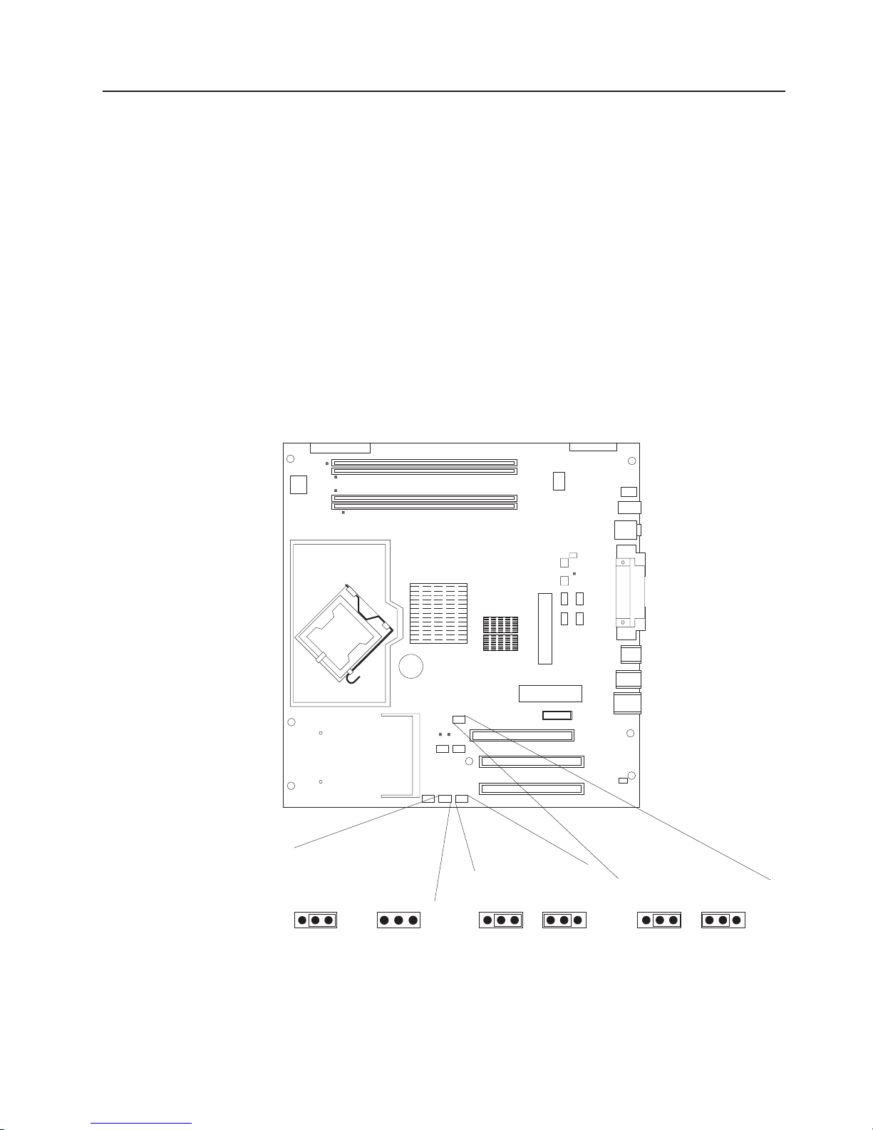
5. Locate the CMOS recovery jumper (JBAT1) on the system board, removing
any adapters that impede access to the jumper. The following illustration
shows the location of the jumper on the system board.
Boot Block Jumper (J1)
Boot Block
Default
(pins 1 and 2)
3 2 1
6. Move the CMOS recovery jumper from pins 1 and 2 to pins 2 and 3.
7. Wait 60 seconds; then, return the CMOS recovery jumper to pins 1 and 2.
8. Replace any adapters that were removed; then, replace the side cover (see
(Recover)
(No Jumper)
3 2 1
IEEE 1394 ( Firewire )
enable / disable jumper
DisableDefault
3 2 13 2 1
Clear CMOS Jumper (JBAT1)
RecoverDefault
3 2 13 2 1
“Replacing the side cover” on page 33).
You can now start the computer one time and start the Configuration/Setup
Utility program without having to use the power-on password. At this time, you
can either delete the old password or set a new user password. If you do not
change or delete the password, the next time you start the computer the
original user password will be reinstated.
9. Connect the computer to a power source, keyboard, monitor, and mouse.
10. Turn on the computer. The Configuration/Setup Utility program starts.
11. Follow the instructions to erase the existing password or create a new
password.
12. Select Save Settings and press Enter.
Chapter 3. Diagnostics 21
Page 32

Updating BIOS code
Periodically, IBM might post new levels of BIOS code on the Web. Always check the
IBM Support Web site at http://www.ibm.com/pc/support/ for the latest level of BIOS
code, device drivers, documentation, and hints and tips. Yo u can use one of the
following methods to update (flash) the BIOS code on the computer:
v Download the BIOS code update file directly to the hard disk.
v Download the BIOS code update file to a diskette (use an external USB portable
diskette drive if you have not installed an integrated diskette drive); then, update
the BIOS code on your computer.
You can order an optional IBM USB Portable Diskette Drive. For a list of
supported options for your computer, see http://www.ibm.com/pc/compat/.
v Download the BIOS code update file to a CD using a writable optional device
(CD-RW drive); then, start the computer with the CD in the CD-ROM drive to
update the BIOS code on the computer.
file is available for each method. The description next to each file indicates the
One
type of medium to which you can download the file. A readme file is available with
instructions for installing the BIOS code update.
Complete the following steps to download the BIOS (flash) update files:
1. Go to http://www.ibm.com/pc/support/.
2. In the Downloads category, click Downloads & drivers.
3. In the Brand field, select IntelliStation.
4. In the Family field, select IntelliStation M Pro.
5. In the Type field, select 6225 or 6228 and click Continue.
6. In the Filter by category field, select BIOS (system).
7. Scroll down and select the applicable file for the operating system.
8. Select the file for the type of medium you want to use; then, download the file
and install it.
9. Restart the computer.
See the readme file for additional information about how to install the image files.
Note: Always reset the Configuration/Setup Utility program to the default values
after updating the BIOS code.
22 IntelliStation M Pro Types 6225 and 6228: Hardware Maintenance Manual and Troubleshooting Guide
Page 33
Recovering from a POST/BIOS update failure
Note: Yo u can download a file to create the POST/BIOS recovery diskette or CD
from http://www.ibm.com/pc/support/. For more information, see Appendix A,
“Getting help and technical assistance,” on page 113.
If power to your computer is interrupted while POST/BIOS code is being updated
(flash update), your computer might not restart (reboot) correctly. If this happens,
complete the following steps to recover:
1. Review Appendix B, “Safety information,” on page 115 and “Handling
static-sensitive devices” on page 29
2. Turn off the computer and all attached devices. See “Turning off the computer”
on page 6 for instructions.
3. Disconnect the power cord.
4. Remove the cover.
5. Locate the boot block recovery jumper (J1) on the system board. Remove any
adapters that impede access to the jumper. The following illustration shows the
location of the boot block jumper on the system board.
(pins 1 and 2)
6. Remove the boot block recovery jumper from pins 1 and 2.
7. Replace any adapters that were removed; then, replace the cover.
8. Connect the computer to a power source, keyboard, monitor, and mouse.
9. Insert the POST/BIOS recovery (flash) diskette or CD into the diskette drive or
CD-ROM drive.
Boot Block Jumper (J1)
Boot Block
Default
3 2 1
(Recover)
(No Jumper)
3 2 1
IEEE 1394 ( Firewire )
enable / disable jumper
DisableDefault
3 2 13 2 1
Clear CMOS Jumper (JBAT1)
RecoverDefault
3 2 13 2 1
Chapter 3. Diagnostics 23
Page 34

10. Turn on the computer and the monitor.
11. After the update is completed, remove the diskette or CD from the diskette
drive or CD-ROM drive.
12. Turn off the computer and monitor.
13. Disconnect all power cords; then, remove the computer cover.
14. Return the boot block recovery jumper to pins 1 and 2.
15. Replace the computer cover; then, reconnect all external cables and power
cords, and turn on the peripheral devices.
16. Turn on the computer to restart the operating system.
Clearing hardware option conflicts and saving option ROM space
This section provides information about clearing hardware option conflicts and
saving option ROM space on your computer. Do not disable this jumper if you plan
to install FireWire devices on your computer.
Complete the following steps to set the IEEE 1394 (FireWire) enable/disable jumper
and clear hardware option conflicts or to save option ROM space:
1. Review Appendix B, “Safety information,” on page 115 and “Handling
static-sensitive devices” on page 29
2. Turn off the computer and all attached devices.
3. Disconnect the power cord.
4. Remove the side cover.
24 IntelliStation M Pro Types 6225 and 6228: Hardware Maintenance Manual and Troubleshooting Guide
Page 35

5. Locate the IEEE 1394 (FIreWire) enable/disable jumper on the system board.
Remove any adapters that impede access to the jumper. The following
illustration shows the location of the jumper on the system board.
Power checkout
Boot Block Jumper (J1)
IEEE 1394 ( Firewire )
enable / disable jumper
DisableDefault
3 2 13 2 1
Clear CMOS Jumper (JBAT1)
RecoverDefault
3 2 13 2 1
Default
(pins 1 and 2)
3 2 1
Boot Block
(Recover)
(No Jumper)
3 2 1
6. Move the IEEE 1394 (FireWire) enable/disable jumper from pins 1 and 2 to pins
2 and 3 to set it to disabled. The default is enabled.
7. Replace any adapters that were removed; then, replace the side cover.
8. Connect the computer to a power source, keyboard, monitor, and mouse.
9. Turn on the computer.
Power problems can be difficult to solve. For example, a short circuit can exist
anywhere on any of the power distribution buses. Usually, a short circuit will cause
the power subsystem to shut down because of an overcurrent condition.
Note: To help isolate whether a power problem is in the power distribution bus or in
the power supply, check the power supply error LED on the rear of the
computer. If this amber LED is lit, replace the power supply.
A general procedure for troubleshooting power problems is as follows:
1. Turn off the computer, and disconnect all ac power cords.
2. Check for loose cables in the power subsystem. Also check for short circuits, for
example, if there is a loose screw causing a short circuit on a circuit board.
Chapter 3. Diagnostics 25
Page 36

3. Remove adapters and disconnect the cables and power connectors to all
internal and external devices until the computer is at the minimum configuration
required to start the computer (see “Undetermined problems” on page 102).
4. Reconnect all ac power cords, and turn on the computer. If the computer starts
successfully, replace adapters and devices one at a time until the problem is
isolated. If the computer does not start from the minimal configuration, replace
FRUs of minimal configuration one at a time until the problem is isolated.
To use this method, you must know the minimum configuration required for the
computer to start (see page “Undetermined problems” on page 102).
Troubleshooting the Ethernet controller
This section provides troubleshooting information for problems that might occur with
the 1 Gbps Ethernet controller.
See the Ethernet controller documentation on the Device Drivers CD for information
about problems that might occur with the 1 Gbps Ethernet controller.
The way the Ethernet controller is tested depends on which operating system you
are using (see the Ethernet controller device-driver file).
You can use the Ethernet wrap test to determine whether a hardware problem is
causing the Ethernet connection to fail. To perform the Ethernet wrap test, use the
wrap plug (IBM part number 60G3981) with the diagnostic tests.
If this testing method indicates that the hardware is functioning normally but the
problem remains, see “Network connection problems” or inform the network
administrator.
Network connection problems
If the Ethernet controller cannot connect to the network, check the following
conditions:
v Make sure that the cable is installed correctly.
The network cable must be securely attached at all connections. If the cable is
attached but the problem remains, try a different cable.
If you set the Ethernet controller to operate at either 100 Mbps or 1000 Mbps,
you must use Category 5 or higher cabling.
v Determine whether the hub supports auto-negotiation. If it does not, try
configuring the integrated Ethernet controller manually to match the speed and
duplex mode of the hub.
v Check the Ethernet controller LEDs on the rear of the computer.
The Ethernet link status LED, on the rear of the computer, is lit when the
Ethernet controller receives a LINK pulse from the hub. If the LED is off, there
might be a defective connector or cable or a problem with the hub.
v Make sure that you are using the correct device drivers, which are supplied with
the computer.
v Check for operating-system-specific causes for the problem.
v Make sure that the device drivers on the client and computer are using the same
protocol.
26 IntelliStation M Pro Types 6225 and 6228: Hardware Maintenance Manual and Troubleshooting Guide
Page 37

Ethernet controller troubleshooting chart
Use the following troubleshooting chart to find solutions to 10/100/1000 Mbps
Ethernet controller problems that have definite symptoms.
Ethernet controller
problem
The computer stopped
running when loading
device drivers.
Ethernet link status LED
does not work.
Data is incorrect or
sporadic.
The Ethernet controller
stopped working when
another adapter was
added to the computer.
The Ethernet controller
stopped working without
apparent cause.
FRU/actions
The PCI BIOS interrupt settings are incorrect.
v Determine whether the interrupt (IRQ) setting assigned to the Ethernet controller is also
assigned to another device in the Configuration/Setup Utility program.
Although interrupt sharing is allowed for PCI devices, some devices do not function well
when they share an interrupt with a dissimilar PCI device. Try changing the IRQ
assigned to the Ethernet controller or the other device. For example, for NetWare
Versions 3 and 4, it is recommended that disk controllers not share interrupts with LAN
controllers.
v Make sure that you are using the most recent device driver available from the World
Wide Web.
v Reseat or replace the adapter.
v Make sure that the hub is turned on.
v Check all connections at the Ethernet controller and the hub.
v Use another port on the hub.
v If the hub does not support auto-negotiation, manually configure the Ethernet controller
to match the hub.
v If you manually configured the duplex mode, make sure that you also manually configure
the speed.
v Reseat or replace the adapter.
v Make sure that you are using Category 5 or higher cabling when operating the computer
at 100 Mbps or at 1000 Mbps.
v Make sure that the cables do not run close to noise-inducing sources such as
fluorescent lights.
v Make sure that the cable is connected to the Ethernet controller.
v Make sure that the PCI system BIOS code is current.
v Reseat the adapter.
v Determine whether the interrupt (IRQ) setting assigned to the Ethernet adapter is also
assigned to another device in the computer. Use the Configuration/Setup Utility program
to determine if this is the case.
Although interrupt sharing is allowed for PCI devices, some devices do not function well
when they share an interrupt with a dissimilar PCI device. Try changing the IRQ
assigned to the Ethernet adapter or the other device.
v Reseat or replace the adapter.
v Try a different connector on the hub.
v Reinstall the device drivers. See the operating-system documentation.
v Reseat or replace the adapter.
Chapter 3. Diagnostics 27
Page 38

28 IntelliStation M Pro Types 6225 and 6228: Hardware Maintenance Manual and Troubleshooting Guide
Page 39

Chapter 4. Customer replacement units
This chapter provides basic instructions for installing hardware options in the
computer. These instructions are intended for users who are experienced with
setting up IBM computer hardware.
Installation guidelines
Before you begin installing options, read the following information:
v Read Appendix B, “Safety information,” on page 115, and the guidelines in
“Handling static-sensitive devices.” This information will help you work safely with
the computer and options.
v Make sure that you have an adequate number of properly grounded electrical
outlets for the computer, monitor, and other devices.
v Back up all important data before you make changes to disk drives.
v Have a small flat-blade screwdriver available.
v When you need to access the inside of the computer to install options, you might
find it easier to lay the computer on its side.
v The blue color on components and labels identifies touch points, where you can
grip a component, move a latch, and so on.
System reliability guidelines
To help ensure proper system cooling and system reliability, make sure that:
v Each of the drive bays has a drive or a filler panel and electromagnetic
compatibility (EMC) shield installed in it.
v There is adequate space around the computer to allow the computer cooling
system to work properly. Leave approximately 50 mm (2 in.) of open space
around the front and rear of the computer. Do not place objects in front of the
fans. For proper cooling and airflow, replace the computer cover before turning
on the computer. Operating the computer for extended periods of time (more
than 30 minutes) with the computer cover removed might damage computer
components.
v You have followed the cabling instructions that come with optional adapters.
v You have replaced a failed fan as soon as possible.
Handling static-sensitive devices
Attention: Static electricity can damage the computer and other electronic
devices. To avoid damage, keep static-sensitive devices in their static-protective
packages until you are ready to install them.
To reduce the possibility of damage from electrostatic discharge, observe the
following precautions:
v Limit your movement. Movement can cause static electricity to build up around
you.
v Handle the device carefully, holding it by its edges or its frame.
v Do not touch solder joints, pins, or exposed circuitry.
v Do not leave the device where others can handle and damage it.
© Copyright IBM Corp. 2004 29
Page 40

v While the device is still in its static-protective package, touch it to an unpainted
metal part of the computer for at least 2 seconds. This drains static electricity
from the package and from your body.
v Remove the device from its package and install it directly into the computer
without setting down the device. If it is necessary to set down the device, put it
back into its static-protective package. Do not place the device on the computer
cover or on a metal surface.
v Take additional care when handling devices during cold weather. Heating reduces
indoor humidity and increases static electricity.
30 IntelliStation M Pro Types 6225 and 6228: Hardware Maintenance Manual and Troubleshooting Guide
Page 41
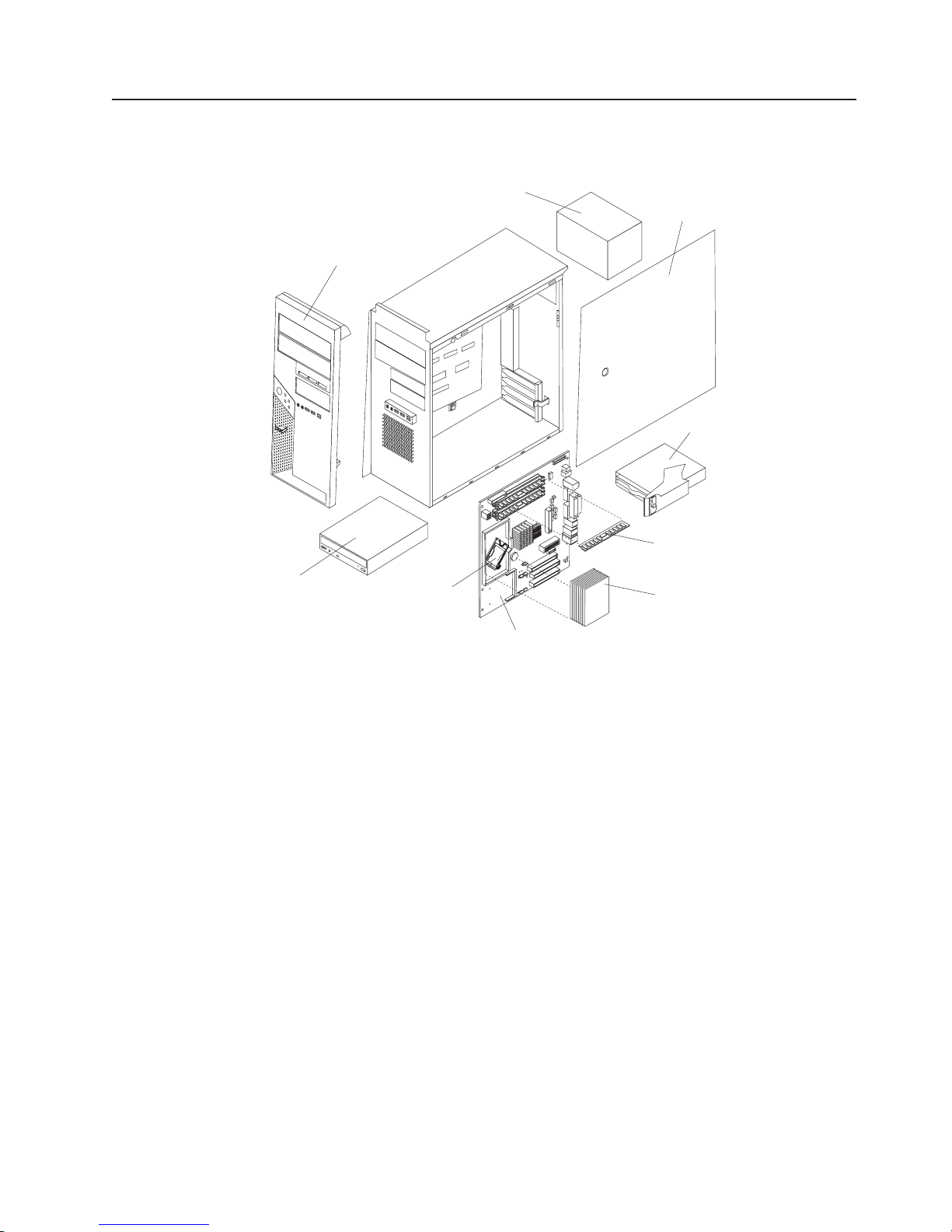
Major components of the IntelliStation M Pro Types 6225 and 6228
The following illustration shows the major components in the M Pro Types 6225 and
6228.
Front bezel
Power supply
Cover
Drive cage
CD-ROM
drive
Microprocessor
Memory modules
Heat sink
System board
Chapter 4. Customer replacement units 31
Page 42

Side cover
This section provides information about removing and installing the side cover.
Removing the side cover
Complete the following steps to remove the side cover of the computer:
Note: It might be easier to lay the computer on its side to perform this procedure.
1. Read Appendix B, “Safety information,” on page 115, and the “Installation
guidelines” on page 29.
2. Turn off the computer and all attached devices (see “Turning off the computer”
on page 6); then, disconnect all power cords and external cables.
3. Press the cover-release button on the side of the computer, and push the side
cover toward the rear of the computer. Lift the side cover off the computer and
set it aside.
To replace the side cover, see “Replacing the side cover” on page 33.
Attention: For proper cooling and airflow, replace the cover before turning on the
computer. Operating the computer with the cover removed might damage computer
components.
32 IntelliStation M Pro Types 6225 and 6228: Hardware Maintenance Manual and Troubleshooting Guide
Page 43

Replacing the side cover
If you removed the bezel, reinstall it before you replace the side cover. See
“Removing and Installing the Bezel” on page 34.
Complete the following steps to replace the side cover:
1. Make sure that all cables, adapters, and other components are installed and
seated correctly and that you have removed all work tools or parts from inside
the computer.
2. Install the side cover by placing it into position on the computer. Be certain that
the lip on the bottom of the cover rests on the ledge on the bottom of the
chassis. Slide the side cover forward to lock the side cover.
3. Reconnect the external cables and power cords to the computer; then, connect
the power cords to electrical outlets.
4. Turn on the attached devices; then, turn on the computer.
Chapter 4. Customer replacement units 33
Page 44

Removing and Installing the Bezel
When working with some options, such as a CD-ROM drive or diskette drive, you
must first remove the bezel to access the option.
Complete the following steps to remove the bezel:
1. Read Appendix B, “Safety information,” on page 115, and the “Installation
guidelines” on page 29.
2. Turn off the computer and all attached devices (see “Turning off the computer”
on page 6); then, disconnect all power cords and external cables.
3. Remove the side cover (see “Removing the side cover” on page 32).
4. Press the bezel release button to disengage the bezel.
Bezel release
button
5. Carefully remove the bezel from the computer; then, set the bezel aside.
To reinstall the bezel, reverse the previous steps.
34 IntelliStation M Pro Types 6225 and 6228: Hardware Maintenance Manual and Troubleshooting Guide
Page 45

Removing and replacing the microprocessor fan assembly
Before you begin:
v Read the “Installation guidelines” on page 29.
v Read Appendix B, “Safety information,” on page 115.
v Review the information in “System reliability guidelines” on page 29.
remove the microprocessor fan assembly, complete the following steps:
To
1. Turn off the computer, if it is on.
2. Disconnect the power cord from the power source and from the computer; then,
disconnect all external cables.
3. Remove the side cover (see “Removing the side cover” on page 32).
4. Stand the computer upright if it is lying on its side.
5. Remove the front bezel (see “Removing and Installing the Bezel” on page 34).
6. Lay the computer on its left side.
Important: When disconnecting cables, note the cable routing and connector
labels for use during installation.
7. Disconnect the fan assembly power cable from the system board (see “System
board internal connectors” on page 78 for the location of the microprocessor fan
connector).
Chapter 4. Customer replacement units 35
Page 46

8. Press the extender release tab toward the top of the chassis and remove the
extender by pulling up on the extender handle.
Release lever
Handle
Clips
Release tab
Extender
Extender handle
Important: Two metal clips in the front panel of the chassis provide additional
support for the fan assembly during shipping. If necessary, press on
the raised edge of each clip to flatten it into the front panel before
attempting to remove the fan assembly. These clips do not have to
be restored when the fan assembly is replaced.
9. Press down and hold the fan assembly release lever. While holding the lever,
grasp the handle and carefully pull the fan assembly up to disengage the tabs
from the front of the chassis; then, lift the assembly out of the chassis.
To replace the microprocessor fan assembly, reverse the previous steps.
36 IntelliStation M Pro Types 6225 and 6228: Hardware Maintenance Manual and Troubleshooting Guide
Page 47

Removing and replacing the SCSI daughter card
Before you begin:
v Read the “Installation guidelines” on page 29.
v Read Appendix B, “Safety information,” on page 115.
v Review the information in “System reliability guidelines” on page 29.
To remove the SCSI daughter card, complete the following steps:
1. Turn off the computer, if it is on.
2. Disconnect the power cord from the power source and from the computer; then,
disconnect all external cables.
3. Lay the computer on its left side.
4. Remove the side cover (see “Removing the side cover” on page 32).
5. Remove any long adapters that might impede access to the SCSI daughter
card.
6. Disconnect the SCSI cable from the card.
SCSI daughter card
SCSI cable connector
Chapter 4. Customer replacement units 37
Page 48
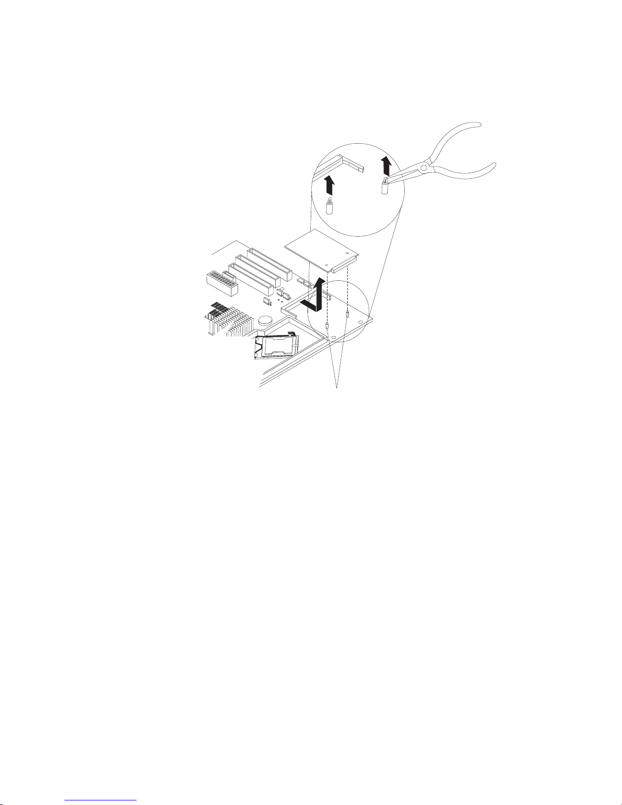
7. Gently pull up on the SCSI card until it disengages from the plastic standoffs. If
the standoffs come away from the system board with the SCSI card, gently pull
them out of the SCSI card and push them back into their apertures on the
system board.
Plastic
standoff
Note: Yo u can also gently pinch the top of each standoff using needle-nose
pliers and then pull the SCSI card away.
8. Carefully pull the card toward the front of the computer to remove it from the
system board.
9. Lift the card out of the computer.
To replace the SCSI daughter card, reverse the previous steps.
38 IntelliStation M Pro Types 6225 and 6228: Hardware Maintenance Manual and Troubleshooting Guide
Page 49

Installing an adapter
The following notes describe the types of adapters that your computer supports and
other information that you might consider when installing an adapter. See “System
board option connectors” on page 77 for an illustration of the adapter slot locations.
v Read the documentation that comes with your operating system.
v Locate the documentation that comes with the adapter and follow those
instructions in addition to the instructions in this chapter. If you need to change
the switch or jumper settings on your adapter, follow the instructions that come
with the adapter.
v Your computer comes with adapter connectors, or slots. The PCI Express x16
video adapter is installed in slot 2. Yo u can install up to three additional optional
adapters in your computer in slot 1 (PCI Express x1) and PCI slots 3 and 4.
v You can install only 33 MHz/32-bit adapters in PCI slots 3 and 4.
v You can install full-length adapters in PCI slots 3 and 4. None of the expansion
slots are hot-plug slots.
v For slot 3 and 4, your computer supports 5.0 V signaling and universal PCI
adapters; it does not support 3.3 V signaling adapters.
v The computer scans the adapters in the following sequence to assign system
resources: PCI Express x1 slot (slot 1), PCI Express x16 slot (slot 2), PCI
expansion slot 1 (slot 3), PCI expansion slot 2 (slot 4), and mini-PCI 1 slot. Then,
the computer starts the PCI devices in the following order, if you have not
changed the default startup sequence: PCI Express x1, PCI Express x16,
system-board IDE or small computer system interface (SCSI) devices, and PCI
slot 3, PCI slot 4, and then the mini-PCI 1.
v Your computer comes with integrated IEEE 1394 (FireWire) support.
v For a list of supported options for your computer, go to http://www.ibm.com/pc/;
then, select your country and navigate to the list of options for your computer.
Complete the following steps to install an adapter:
1. Read Appendix B, “Safety information,” on page 115, and “Handling
static-sensitive devices” on page 29
2. Turn off the computer and all attached devices (see “Turning off the computer”
on page 6; then, disconnect all external cables and power cords.
3. Remove the side cover (see “Removing the side cover” on page 32).
4. Determine which PCI slot you will use for the adapter. Check the instructions
that come with the adapter for any requirements, restrictions, or cabling
instructions. It might be easier to route cables before you install the adapter.
5. If an adapter is already installed in the slot, remove it using one of the
following procedures and place it on a static-protective surface:
v For full-length adapters, rotate the rear adapter-retention bracket to the open
(unlocked) position; then, release the adapter from the front
adapter-retention bracket. Grasp the adapter and pull it out of the slot.
Attention: To remove an adapter from the PCI Express x16 slot (slot 2),
you must press on the adapter-retention tab while pulling the adapter out of
the slot.
Chapter 4. Customer replacement units 39
Page 50
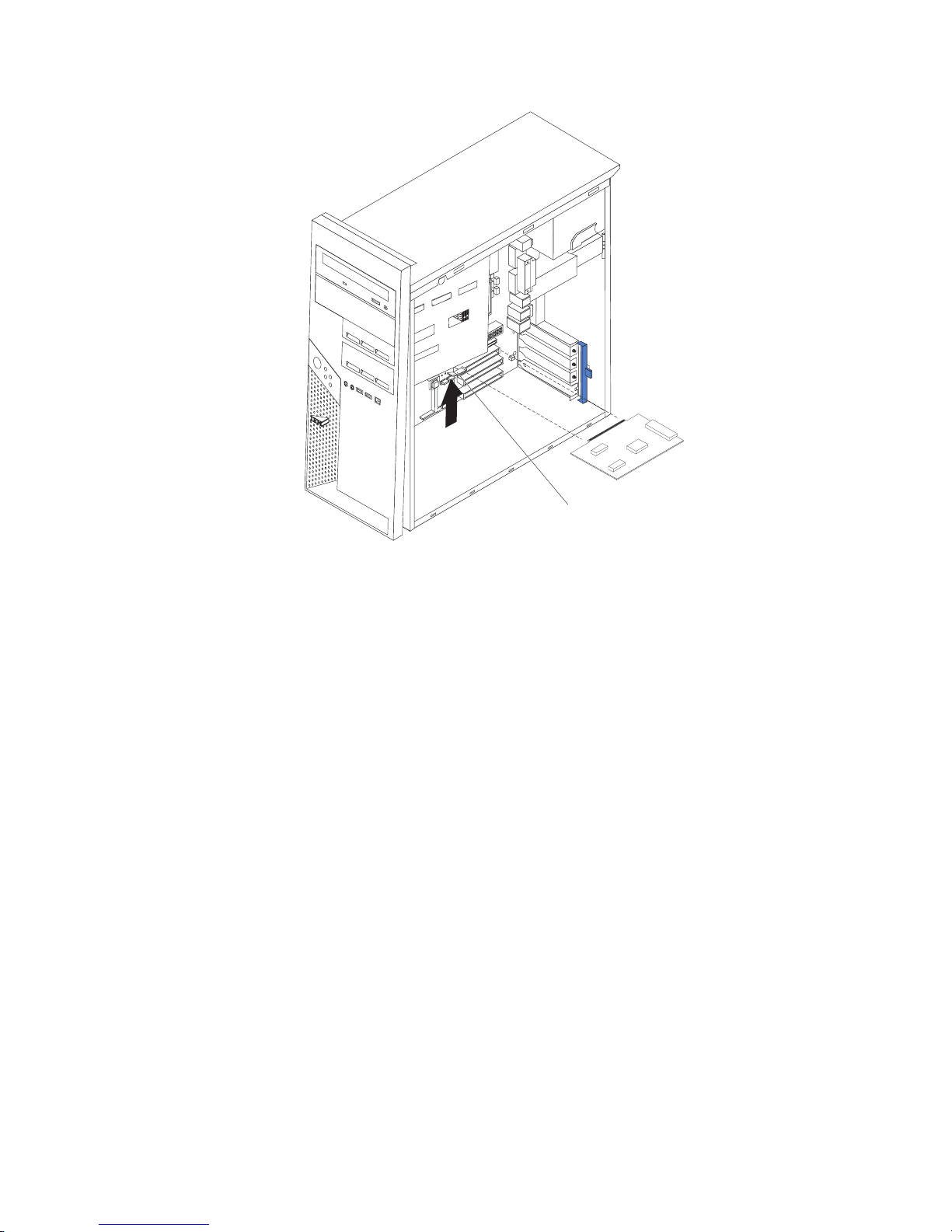
Adapter-retention tab
v For smaller adapters, rotate the rear adapter-retention bracket to the open
(unlocked) position. Grasp the adapter and pull it out of the slot.
If the slot is empty, remove the expansion-slot cover. From the rear of the
computer, press on the slot cover. Grasp it and pull it out of the expansion slot.
Store it in a safe place for future use.
Attention: Expansion-slot covers must be installed in all empty slots. This
maintains the electronic emissions standards of the computer and ensures
proper ventilation of computer components.
6. Follow the instructions that come with the adapter to set jumpers or switches, if
any.
40 IntelliStation M Pro Types 6225 and 6228: Hardware Maintenance Manual and Troubleshooting Guide
Page 51

Attention: Avoid touching the components and gold-edge connectors on the
adapter.
7. If you are installing a full-length adapter, remove the blue adapter guide (if any)
from the end of the adapter.
Adapter guide
Attention: Make sure that the adapter is correctly seated in the expansion
slot before you turn on the computer. Incomplete installation of an adapter
might damage the system board or the adapter.
8. Carefully grasp the adapter by the top edge or upper corner and move the
adapter directly from the static-protective package to the adapter slot. Align the
adapter with the expansion slot guides; then, press the adapter firmly into the
expansion slot.
Attention: Make sure that the adapter is correctly seated in the expansion
slot before you turn on the computer. Incomplete installation of an adapter
might damage the system board or the adapter.
Rear adapter-retention
bracket
Chapter 4. Customer replacement units 41
Page 52

9. Rotate the rear adapter-retention bracket to the closed (locked) position.
10. Connect required cables to the adapter. Route cables so that they do not block
the flow of air from the fans. If you are installing an optional SCSI adapter, see
“Cabling an optional SCSI adapter” on page 43 for additional information.
11. If you have another adapter to install, repeat steps 4 through 10.
12. If you have installed a full-length adapter, press down on the top tab of the
front adapter-retention bracket to lock it in place (the tab is inside the fan
compartment that is next to the front adapter-retention bracket).
Note: If any adapter in your computer is large or has heavy cables attached to
it, you can secure the adapter with a screw. Insert one backup
expansion-slot screw through the top of each adapter bracket into the
screw hole and secure the adapter before proceeding to the next step.
13. If you have other options to install, do so now; otherwise, replace the side
cover (see“Replacing the side cover” on page 33), reconnect the external
cables and power cords, and turn on the computer.
42 IntelliStation M Pro Types 6225 and 6228: Hardware Maintenance Manual and Troubleshooting Guide
Page 53

Cabling an optional SCSI adapter
You can install an optional SCSI adapter in your computer to control the internal
hard disk drives. With a SCSI adapter installed, you can configure the internal hard
disk drives into disk arrays. Yo u can also cable a SCSI adapter to external hard
disk drives. See your SCSI adapter option documentation for complete instructions
for installing a SCSI adapter in your computer and for additional information about
SCSI adapters.
Notes:
1. An optional SCSI adapter is required for you to connect external SCSI devices.
2. The SCSI cables that are used by the integrated SCSI controller cannot be
used with an optional SCSI adapter.
Complete the following steps to cable an optional SCSI adapter:
1. Install the SCSI adapter (see “Installing an adapter” on page 39).
2. Connect the SCSI-signal cable to the adapter and to one or more of the
signal-cable connectors on the rear of the SCSI devices.
SCSI adapter
SCSI signal cable
connector
SCSI signal cable
3. Connect the SCSI-activity-indicator cable to the adapter and to the SCSI-LED
connector on the system board. See “System board option connectors” on page
77 for the location of the SCSI-LED connector.
4. Complete the installation of the optional SCSI adapter.
Chapter 4. Customer replacement units 43
Page 54

Removing and replacing the front I/O panel
Complete the following steps to remove the front input/output (I/O) panel:
1. Read Appendix B, “Safety information,” on page 115, “Handling static-sensitive
devices” on page 29 and the “Installation guidelines” on page 29.
2. Turn off the computer and attached devices.
3. Disconnect the power cord from the power source and from the computer;
then, disconnect all external cables.
4. Remove the side cover (see “Removing the side cover” on page 32.
5. Remove the front bezel (see “Removing and Installing the Bezel” on page 34).
6. Remove the microprocessor fan assembly (see “Removing and replacing the
microprocessor fan assembly” on page 35).
Important: When disconnecting cables, note the cable routing and connector
labels for use during installation.
7. Disconnect the internal IEEE 1394 (Firewire) cable and front-panel cable from
the system board (see “System board external connectors” on page 79 and
“System board internal connectors” on page 78 for connector locations).
8. Disconnect the power switch/LED assembly cable from the back of the I/O
card.
9. Remove the I/O panel screw on the front of the computer.
10. Slide the I/O panel toward the right side of the computer (up, if the computer is
on its side) to disengage it from the computer front panel; then, carefully pull
the I/O panel, card, and cables out of the opening in the front panel.
11. Disconnect the front-panel cable from the back of the I/O card.
replace the front I/O panel, reverse the previous steps.
To
44 IntelliStation M Pro Types 6225 and 6228: Hardware Maintenance Manual and Troubleshooting Guide
Page 55
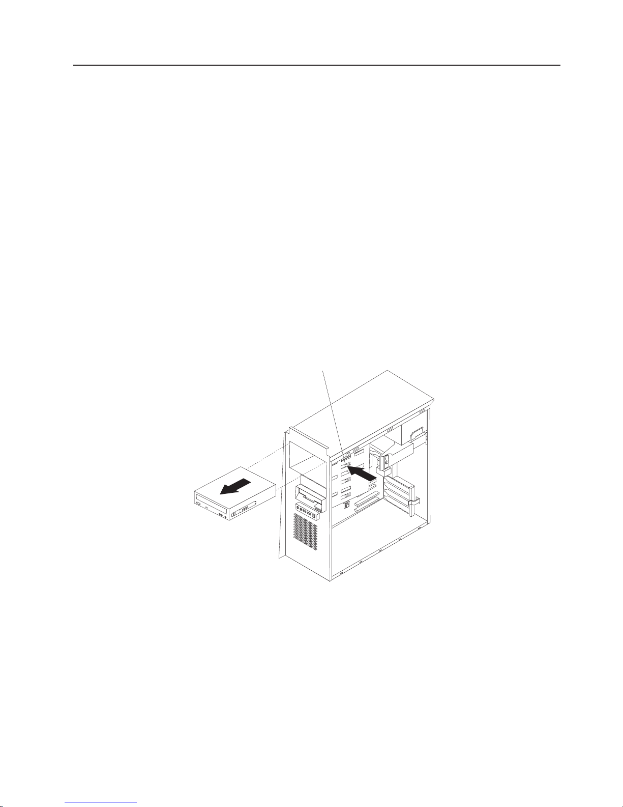
Removing and replacing the CD-ROM or CD-RW drive
To remove the CD-ROM or CD-RW drive, complete the following steps:
1. Read Appendix B, “Safety information,” on page 115, “Handling static-sensitive
devices” on page 29 and the “Installation guidelines” on page 29.
2. Turn off the computer, if it is on.
3. Disconnect the power cord from the power source and from the computer; then,
disconnect all external cables.
4. Remove the side cover (see “Removing the side cover” on page 32).
5. Stand the computer upright if it is lying on its side.
6. Remove the front bezel (see “Removing and Installing the Bezel” on page 34).
Note: To provide extra space for the removal, it might be helpful to Rotate the
internal drive cage out of the computer (see “Rotating the internal drive
cage” on page 73).
Important: When disconnecting cables, note the cable routing and connector
labels for use during installation.
7. Disconnect the cables from the rear of the CD-ROM or CD-RW drive.
8. Press and hold the blue raised button on the side of the drive cage to release
the drive, and gently pull the CD-ROM or CD-RW drive out of the front of the
computer.
Release button
Chapter 4. Customer replacement units 45
Page 56

9. Remove the retainer clip from the side of the drive; note its orientation for use
during installation.
Retainer clip
To replace the CD-ROM or CD-RW drive, see “Installing a drive in bay 2, 3, or 4”
on page 48.
46 IntelliStation M Pro Types 6225 and 6228: Hardware Maintenance Manual and Troubleshooting Guide
Page 57

Installing a drive
Depending on your computer model, one or more of the following drives might be
installed in your computer:
v Diskette (optional)
v Hard disk
v CD-ROM, CD-RW, or DVD/CD-RW combo
Your computer comes with an IDE CD-ROM or DVD/CD-RW drive in bay 1 and a
3.5-in. hard disk drive in bay 5.
Bay 1
Bay 2
Bay 3
Bay 4
Bay 5
The following notes describe the types of drives that your computer supports and
other information that you must consider when installing drives:
v Diskette drives, tape drives, CD-ROM, DVD/CD-RW, and DVD-ROM drives are
examples of removable-media drives. Yo u can install removable-media drives in
bays 1, 2, 3, and 4 only.
v You can install a 3.5-in. slim-high or 5.25-in. half-high removable-media drive,
such as a tape backup drive, in bay 2.
v You can install only a 3.5-in., slim-high drive in bay 3 or 4.
v The IntelliStation M Pro Types 6225 and 6228 support only one diskette drive.
v There are four serial ATA hard disk drive connectors on the system board.
v You can mix and match SCSI and serial ATA drives in bays 3, 4, and 5.
v The electromagnetic interference (EMI) integrity and cooling of the computer are
protected by having all bays and PCI slots covered or occupied. When you install
a drive or PCI adapter, save the EMC shield and filler panel from the bay or the
PCI adapter slot cover in the event you later remove the option.
v For a complete list of supported options for your computer, go to
http://www.ibm.com/pc/; then, select your country and navigate to the list of
options for your computer.
Chapter 4. Customer replacement units 47
Page 58

Installing a drive in bay 2, 3, or 4
Complete the following steps to install a drive in bay 2, 3, or 4:
1. Read Appendix B, “Safety information,” on page 115, the guidelines in
“Handling static-sensitive devices” on page 29 and the documentation that
comes with your drive.
2. Turn off the computer and all attached devices (see “Turning off the computer”
on page 6); then, disconnect all external cables and power cords.
3. Remove the side cover (see “Removing the side cover” on page 32).
4. Remove the bezel (see “Removing and Installing the Bezel” on page 34).
5. Use a screwdriver to pry the filler panel and EMC shield away from the
computer.
Filler panel
EMC shield
Drive retainer
clip
48 IntelliStation M Pro Types 6225 and 6228: Hardware Maintenance Manual and Troubleshooting Guide
Page 59
Note: If you are installing a drive that contains a laser, observe the following
safety precaution.
Statement 3:
CAUTION:
When laser products (such as CD-ROMs, DVD drives, fiber optic devices,
or transmitters) are installed, note the following:
v Do not remove the covers. Removing the covers of the laser product
could result in exposure to hazardous laser radiation. There are no
serviceable parts inside the device.
v Use of controls or adjustments or performance of procedures other
than those specified herein might result in hazardous radiation
exposure.
DANGER
laser products contain an embedded Class 3A or Class 3B laser
Some
diode. Note the following.
Laser radiation when open. Do not stare into the beam, do not view
directly with optical instruments, and avoid direct exposure to the
beam.
6. Touch the static-protective package containing the drive to any unpainted metal
surface on the computer; then, remove the drive from the package and place it
on a static-protective surface.
7. Set any jumpers or switches on the drive according to the documentation that
comes with the drive.
Note: Yo u might find it easier to install the new drive into the appropriate
opening on the front, and then attach the cables.
8. Use one of the following procedures, depending on which bay you are
installing the drive in:
v To install a drive in bay 2, complete the following steps:
a. Remove the large drive clip that is attached to the side of bay 2 of the
drive cage for bays 1, 2, 3, and 4 (see the figure in step 5). Slide the
drive clip to the left to disengage it from the drive cage; then, snap the
drive clip into the screw holes on the side of the drive.
b. If you are installing a 5.25-in. drive in bay 2, slide the drive into the drive
bay until it snaps in place.
Chapter 4. Customer replacement units 49
Page 60

v To install a drive in bay 3 or 4, complete the following steps:
Note: Only a 3.5-in. device can be installed in bay 3 or 4.
– If you are installing an external media device, complete the following
steps:
a. Remove the small drive clip that is attached to the bottom of the drive
cage for bays 1, 2, 3, and 4 (see the figure in step 5). Slide the drive
clip to disengage it from the drive cage; then, snap the drive clip into
the screw holes on the side of the drive.
b. Slide the drive into the drive bay until it snaps in place.
If you are installing a hard disk drive, complete the following steps:
–
a. Push the drive into the bay from the rear of the drive cage.
b. Use the two screws to attach the drive to the drive cage.
9. Determine whether the drive is an IDE, SATA, or SCSI device; then, connect
one end of the applicable signal cable into the back of the drive and make
sure that the other end of this cable is connected into the applicable IDE,
SATA, or SCSI connector.
10. Route the signal cable so that it does not block the airflow to the rear of the
drives or over the microprocessor.
11. If you have another drive to install or remove, do so now.
12. Connect the power cable to the back of the drive. The connectors are keyed
and can be inserted only one way.
13. If you have other options to install or remove, do so now; otherwise, replace
the bezel (see “Removing and Installing the Bezel” on page 34).
Installing a hard disk drive in bay 5
Bay 5 is inside the computer below the power supply within a drive cage.
Note: When installing options, you might find it easier to work with the computer
lying on its side.
Before you install a hard disk drive in bay 5, read the following information:
v Read the documentation that comes with the drive for cabling instructions.
v Route the cable before you install the drive. Do not block the airflow from the
fans.
Complete
1. Read Appendix B, “Safety information,” on page 115, the guidelines in
2. Turn off the computer and all attached devices (see “Turning off the computer”
3. Remove the side cover (see “Removing the side cover” on page 32).
4. Push the drive-cage retention latch toward the front of the computer and hold
the following steps to install a drive in bay 5:
“Handling static-sensitive devices” on page 29.
on page 6); then, disconnect all external cables and power cords.
the latch in place. While holding the latch in place, grasp the drive-cage handle
and rotate the cage until it locks into place with the drive-cage retention latch.
The installed drive will face you.
Note: As you rotate the drive cage, make sure the hard disk drive cables or
other internal cables do not impede the rotation of the drive cage.
50 IntelliStation M Pro Types 6225 and 6228: Hardware Maintenance Manual and Troubleshooting Guide
Page 61

Drive-cage
retention latch
Drive-cage
handle
5. Slide the existing drive out of the drive bay. Remove the drive from the drive
tray by pulling on the handle; then, slide the drive out of the drive tray.
Drive-tray
handle
6. Touch the static-protective package containing the new drive to any unpainted
metal surface on the computer; then, remove the drive from the package and
place it on a static-protective surface.
7. Set any jumpers or switches on the new drive according to the documentation
that comes with the drive.
Chapter 4. Customer replacement units 51
Page 62

8. Attach the new drive to the drive tray. Place the drive on the drive tray and
align the holes on the drive with the mounting pins on the drive tray. Gently
pull both sides of the drive tray outward and insert the mounting pins into the
holes on the drive.
9. Align the drive assembly with the guide rails in the bay (make sure that the
connector end of the drive is facing you).
10. Determine whether the new drive is a SATA or SCSI device; then, connect one
end of the applicable signal cable into the back of the drive and the other end
of this cable into the applicable SATA or mini-PCI SCSI connector. See “Power
and signal cables for internal drives” on page 53 for additional information
about cabling drives and “System board option connectors” on page 77 for the
location of SATA and mini-PCI SCSI connectors on the system board. If there
are open connectors on the cables that connect existing SATA or SCSI drives,
these cables can be used to connect the new drive.
11. Route the signal cable so that it does not block the airflow to the rear of the
drives or over the microprocessor.
12. Route the signal cable so that it does not block the airflow to the rear of the
drives or over the microprocessor.
13. Connect the power cable to the back of the drive. The connectors are keyed
and can be inserted only one way.
14. Push the drive-cage retention latch toward the front of the computer; then,
rotate the drive cage back into the computer.
Note: As you rotate the drive cage, make sure the hard disk drive cables or
other internal cables do not impede the rotation of the drive cage.
15. If you have other options to install or remove, do so now.
52 IntelliStation M Pro Types 6225 and 6228: Hardware Maintenance Manual and Troubleshooting Guide
Page 63

Power and signal cables for internal drives
Your computer uses cables to connect IDE, SATA, and SCSI devices to the power
supply and to the system board. (See “System board internal connectors” on page
78 for the location of system-board connectors.) Review the following information
before connecting power and signal cables to internal drives:
v The drives that are preinstalled in your computer come with power and signal
cables attached. If you replace any drives, remember which cable is attached to
which drive.
v When you install a drive, make sure that one of the drive connectors of the signal
cable is connected to the drive and that the connector at the other end of the
signal cable is connected to the system board.
v If you have only one IDE device on a cable, it must be set as a primary device.
v If two IDE devices are used on a single cable, one must be designated as the
primary device and the other as the secondary device; otherwise, the computer
might not recognize some of the IDE devices. The primary and secondary
designation is determined by switch or jumper settings on each IDE device.
The following cables are provided:
v Power cables: Four-wire power cables connect the drives to the power supply.
At the end of these cables are plastic connectors that can be attached to
different drives; these connectors vary in size. Yo u can use either a four-wire
power cable or serial ATA power cable with serial ATA drives, but do not use both
at the same time (use one or the other).
v Signal cables: Signal cables are typically flat cables, also called ribbon cables,
that connect parallel IDE, SATA, SCSI, and diskette drives to the system board.
Two or three types of signal cable come with your computer:
– IDE: The wider IDE signal cable has three connectors. One of these
connectors is attached to the drive, one is a spare, and the third is attached to
the primary IDE connector on the system board.
The CD-ROM drive is attached to an ATA 100 signal cable. ATA 100 signal
cables are color-coded. The blue connector is attached to the system board.
The black connector is attached to the primary IDE device. The gray middle
connector is attached to the secondary IDE device.
– Diskette drive (optional): The narrower signal cable has two connectors.
One is attached to the diskette drive, and the other is attached to the diskette
drive connector on the system board.
– Serial ATA: The narrower, black signal cable has two connectors. One is
attached to the SATA drive, and the other is attached to the connector on the
system board. Each SATA drive comes with a cable. If you install an additional
SATA drive, you will need an additional cable. SATA signal cables should be
connected to the system board connectors (SATA 1 through SATA 4) in
numerical order, starting with SATA 1.
– SCSI: The Ultra320 twisted ribbon cable connects the internal Ultra320 SCSI
hard disk drive to the mini-PCI SCSI connector. This cable has three
additional connectors for attaching more internal SCSI devices.
Chapter 4. Customer replacement units 53
Page 64

Installing memory modules
The following notes describe the types of dual inline memory modules (DIMMs) that
your computer supports and other information that you must consider when
installing DIMMs:
v When you restart the computer after adding or removing a DIMM, the computer
displays a message that the memory configuration has changed.
v Your computer uses industry-standard PC2-3200 double-data-rate 2 (DDR2)
DIMMs.
v The system board contains four DIMM connectors and supports two-way memory
interleaving.
v The DIMM options available for your computer are 256 MB, 512 MB, and 1 GB,
which come in matched pairs. Your computer supports a minimum of 512 MB and
a maximum of 4 GB of system memory.
v Your computer comes with either two 256 MB or two 512 MB memory DIMMs
that are installed in DIMM 1 and DIMM 3 memory connectors. The second pair of
DIMMs must be installed in DIMM 2 and DIMM 4 memory connectors.
v DIMMs must be installed in matched pairs. The DIMMs in each pair must be the
same size, speed, type, and technology as each other but do not have to match
the other pairs. Yo u can mix compatible DIMMs from various manufacturers.
v Install only 1.8 V, 240-pin, DDR2, PC2-3200, unbuffered synchronous dynamic
random-access memory (SDRAM) with error correcting code (ECC) DIMMs.
These DIMMs must be compatible with the latest PC2-3200 SDRAM unbuffered
DIMM specification. For a list of supported options for your computer, go to
http://www.ibm.com/pc/; then, select your country and navigate to the list of
options for your computer.
v The amount of usable memory will be reduced depending on the system
configuration. A certain amount of memory must be reserved for system
resources. The BIOS will display the total amount of installed memory and the
amount of configured memory.
Complete the following steps to install a DIMM:
1. Read Appendix B, “Safety information,” on page 115 and the guidelines in
“Handling static-sensitive devices” on page 29.
2. Turn off the computer and all attached devices (see “Turning off the computer”
on page 6); then, disconnect all external cables and power cords.
3. Remove the side cover (see “Removing the side cover” on page 32).
4. For easier access to the memory modules, rotate the drive cage out of the
computer. Grasp the drive cage and rotate it until it locks into place.
5. Locate the DIMM connectors on the system board. Determine the connectors
into which you will install the DIMMs. Remember that DIMM 1 and DIMM 3
must be paired together (and must be the first installed pair) and DIMM 2 and
DIMM 4 must be paired together. The following table shows the installation
sequence.
Memory installation sequence
DIMMs Slots
2 DIMMs 1, 3
4 DIMMs 1, 3, 2, 4
6. Gently open the retaining clips and, if necessary, remove any existing DIMM.
54 IntelliStation M Pro Types 6225 and 6228: Hardware Maintenance Manual and Troubleshooting Guide
Page 65

7. Touch the static-protective package containing the DIMM to any unpainted
metal surface on the computer. Then, remove the new DIMM from the
package.
8. Gently open the retaining clip on each end of the DIMM slot. Turn the DIMM
so that the pins align correctly with the connector.
9. Insert the DIMM into the connector. Firmly press the DIMM straight down into
the connector by applying pressure on both ends of the DIMM simultaneously.
The retaining clips snap into the locked position when the DIMM is firmly
seated in the connector. If there is a gap between the DIMM and the retaining
clips, the DIMM has not been correctly installed. Open the retaining clips,
remove the DIMM; then, reinsert it.
DIMM
connector 4
DIMM
connector 3
DIMM
connector 2
DIMM
connector 1
10. If you have other options to install or remove, do so now; otherwise rotate the
cage back into the computer.
11. Replace the side cover (see “Replacing the side cover” on page 33).
12. Reconnect the external cables and power cords. Turn on the attached devices,
and turn on the computer.
Chapter 4. Customer replacement units 55
Page 66

Removing and replacing the internal speaker
The internal speaker is located on the front panel of the computer, behind the front
adapter-retention bracket.
Complete the following steps to remove the internal speaker:
1. Read Appendix B, “Safety information,” on page 115, “Handling static-sensitive
devices” on page 29 and the “Installation guidelines” on page 29.
2. Turn off the computer and attached devices.
3. Disconnect the power cord from the power source and from the computer; then,
disconnect all external cables.
4. Remove the side cover (see “Removing the side cover” on page 32.
5. Remove the front bezel (see “Removing and Installing the Bezel” on page 34).
Note: It might be helpful to lay the computer on its left side for the remainder of
this procedure.
6. Remove any full-length adapters that are installed.
Important: When disconnecting cables, note the cable routing and connector
labels for use during installation.
7. Disconnect the speaker wire from the system board (see “System board internal
connectors” on page 78 for the location of the internal speaker connector).
8. Press on the two retaining tabs that hold the front adapter-retention bracket to
the front panel of the computer; then, lift the retention bracket out of the
computer.
9. Slide the speaker out of its retaining tabs and lift it out of the computer.
replace the internal speaker, reverse the previous steps.
To
56 IntelliStation M Pro Types 6225 and 6228: Hardware Maintenance Manual and Troubleshooting Guide
Page 67
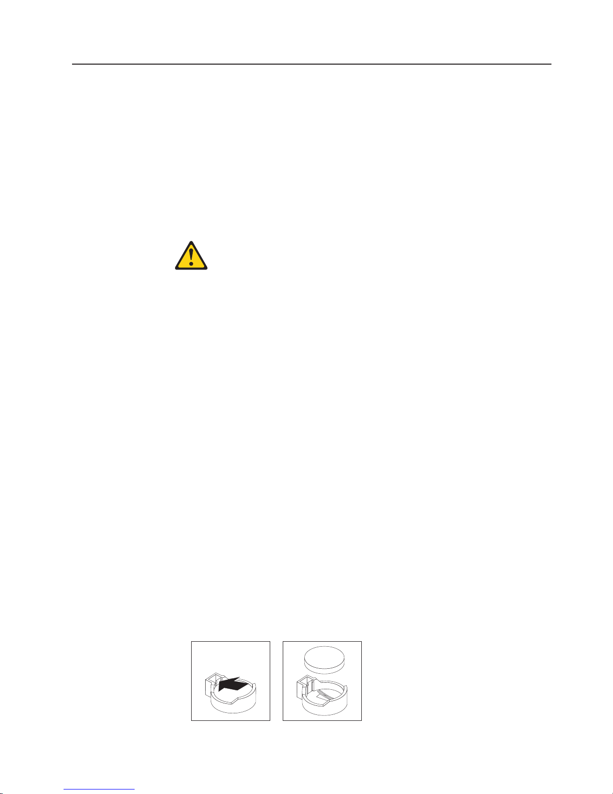
Replacing the battery
When replacing the battery, you must replace it with a lithium battery of the same
type from the same manufacturer. To avoid possible danger, read and follow the
information in Appendix B, “Safety information,” on page 115.
To order replacement batteries, call 1-800-426-7378 within the United States, and
1-800-465-7999 or 1-800-465-6666 within Canada. Outside the U.S. and Canada,
call your IBM reseller or IBM marketing representative.
Note: After you replace the battery, you must reconfigure the system and reset the
system date and time.
Statement 2:
CAUTION:
When replacing the lithium battery, use only IBM Part Number 33F8354 or an
equivalent type battery recommended by the manufacturer. If your system has
a module containing a lithium battery, replace it only with the same module
type made by the same manufacturer. The battery contains lithium and can
explode if not properly used, handled, or disposed of.
Do not:
v Throw or immerse into water
v Heat to more than 100°C (212°F)
v Repair or disassemble
Dispose
Complete the following steps to replace the battery:
of the battery as required by local ordinances or regulations.
1. Review Appendix B, “Safety information,” on page 115 and “Handling
static-sensitive devices” on page 29
2. Follow any special handling and installation instructions that come with the
replacement battery.
3. Turn off the computer and all attached devices. Disconnect all external cables
and power cords; then remove the computer cover. (See “Removing the side
cover” on page 32.)
4. Remove the battery:
a. Use a fingernail to press the top of the battery clip away from the battery.
The battery pops up when released.
b. Use your thumb and index finger to lift the battery from the socket.
Chapter 4. Customer replacement units 57
Page 68

5. Insert the new battery:
a. Tilt the battery so that you can insert it into the socket on the side opposite
the battery clip.
b. Press the battery down into the socket until it clicks into place. Make sure
the battery clip holds the battery securely.
6. Replace the cover, and connect the cables.
7. Turn on the computer.
8. Start the Configuration/Setup Utility program and set configuration parameters.
v Set the system date and time.
v Set passwords if necessary.
v Save the configuration.
58 IntelliStation M Pro Types 6225 and 6228: Hardware Maintenance Manual and Troubleshooting Guide
Page 69
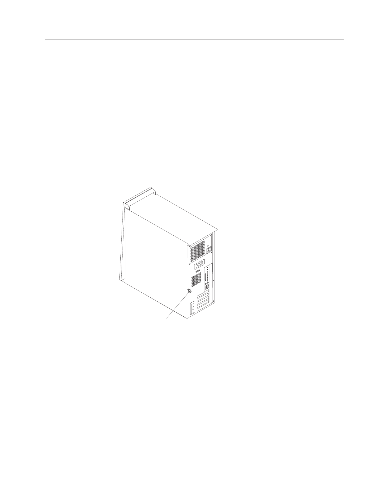
Installing a security cable
To help prevent hardware theft, you can thread a security cable through the cable
loop on the rear of your computer. After you add the security cable, make sure that
it does not interfere with other cables that are connected to the computer.
Before you begin, obtain the following items:
v A security cable
v A lock, such as a combination lock or padlock
Complete
the following steps to install a rope clip:
1. Turn off the computer and all attached devices; then, disconnect all power cords
and external cables.
2. Thread the cable through the cable loop and around an object that is not part of
or permanently secured to the building structure or foundation and from which
the cable cannot be removed. Fasten the cable ends together with a lock. After
you add the security cable, make sure that it does not interfere with other
cables that are connected to the computer.
3. If you have other options to install or remove, do so now.
4. Reconnect the external cables and power cords. Turn on the attached devices,
and turn on the computer.
Cable loop
Chapter 4. Customer replacement units 59
Page 70

Connecting external options
You can connect a number of optional external devices to the connectors on the
rear and front of the computer.
Complete the following steps to connect an external device:
1. Read Appendix B, “Safety information,” on page 115, the guidelines in “Handling
static-sensitive devices” on page 29, and the documentation that comes with
your options.
2. Turn off the computer and all attached devices (see “Turning off the computer”
on page 6).
3. Follow the instructions that come with the option to prepare it for installation and
to connect it to the computer.
If you are attaching a SCSI device, see “Ultra320 SCSI connector” on page 64 for
SCSI ID and cabling information.
60 IntelliStation M Pro Types 6225 and 6228: Hardware Maintenance Manual and Troubleshooting Guide
Page 71

Input/output connectors
Connect optional external devices to the connectors on the front and rear of the
computer.
Your computer has the following input/output (I/O) connectors:
v One audio line in
v Two audio line out
v One audio microphone
v One Ethernet
v Two IEEE 1394 (FireWire) (some models)
v One keyboard
v One mouse
v One parallel
v Two serial
v Eight Universal Serial Bus (USB) 2.0
v One video
The following illustration shows the locations of the connectors on the computer.
Power cord
IEEE 1394 (FireWire)
Line in
Line out
Serial
Parallel
Mouse
Keyboard
USBs
Ethernet
Video
The following sections describe these connectors.
Chapter 4. Customer replacement units 61
Page 72

Audio connectors
Use the audio connectors to connect external audio equipment to the computer.
The following illustration shows the audio connectors.
Line out
(green)
Line in
(blue)
Mic
(pink)
Line in
There is one line-in connector on the rear of the computer. The computer receives
audio signals through this connector from an external audio device.
Line out
There are two line-out connectors, one on the front and one on the rear of the
computer. The computer sends audio signals through this connector to powered
speakers with built-in amplifiers, headphones, a multimedia keyboard, or the audio
line-in connector on a stereo system. The internal speaker in the computer is
disabled when a device is attached to this connector.
Mic
There is one microphone connector on the front of the computer. Connect a
microphone to this connector to record sounds onto the hard disk or to use
speech-recognition software.
Auxiliary-device (pointing-device) connector
There is one auxiliary-device connector on the rear of the computer. Use this
connector to connect a mouse or other pointing device. The following illustration
shows an auxiliary-device connector.
6
4
5
3
1
2
Ethernet (RJ-45) connector
There is one Ethernet connector on the rear of the computer. Use this connector to
connect the computer to a 10-Mbps, 100-Mbps, or 1000-Mbps network. The
following illustration shows an Ethernet connector.
Activity LED
(green)
8
Connect a Category 3, 4, or 5 unshielded twisted-pair (UTP) cable to this connector.
The 100BASE-TX and 1000BASE-T Fast Ethernet standards require Category 5 or
higher cabling.
The Ethernet connector has one LED that indicates Ethernet-link status. When this
LED is lit, it indicates that there is an active connection on the Ethernet port. Activity
between the computer and the network is indicated by the Ethernet transmit/receive
activity LEDs on the front and rear of the computer (see “Server controls,
connectors, and LEDs” on page 4).
62 IntelliStation M Pro Types 6225 and 6228: Hardware Maintenance Manual and Troubleshooting Guide
Link LED
(green)
1
Page 73

IEEE 1394 (FireWire) connector (some models)
There is one 4-pin Institute of Electrical and Electronics Engineers (IEEE) 1394
(FireWire) connector on the front of the computer and one 6-pin IEEE 1394
(FireWire) connector on the rear of the computer. Use these connectors to connect
IEEE 1394 (FireWire) devices. The following illustrations show the IEEE 1394
(FireWire) connectors.
4-pin IEEE 1394 (FireWire) connector (front)
3
4
21
6-pin IEEE 1394 (FireWire) connector (rear)
2
1
Keyboard connector
There is one keyboard connector on the rear of the computer. Use this connector to
connect a PS/2 (non-USB) keyboard. The following illustration shows a keyboard
connector.
6
4
2
If you attach a keyboard to this connector, Universal Serial Bus (USB) ports and
devices are disabled during the power-on self-test (POST).
Parallel connector
There is one parallel connector on the rear of the computer. Use this connector to
connect a parallel device. The following illustration shows a parallel connector.
13
4
6
3
5
5
3
1
1
25
The parallel connector supports three standard IEEE 1284 modes of operation:
standard parallel port (SPP), enhanced parallel port (EPP), and extended capability
port (ECP). If you configure the parallel port to operate in bidirectional mode, it
supports the ECP and EPP modes. When the parallel connector is configured as
bidirectional, use an IEEE 1284-compliant cable that does not exceed 3 meters (9.8
ft). Use the Devices and I/O Ports options in the IBM Configuration/Setup Utility
program to configure the parallel connector as bidirectional.
14
Chapter 4. Customer replacement units 63
Page 74

Serial connectors
There are two serial connectors on the rear of the computer. Use these connectors
to connect serial devices. The following illustration shows a serial connector.
1
69
Ultra320 SCSI connector
Your computer might have a mini-PCI SCSI controller. This single-channel controller
supports an independent, Ultra320 SCSI channel that supports up to 15 SCSI
devices. The SCSI connector for the channel is on the mini-PCI SCSI controller.
The controller has the following features:
v Double-transition clocking to achieve up to 320 MBps (megabytes per second)
data-transfer rates
v Domain name validation to negotiate compatible data-transfer speeds with each
device
v Cyclic-redundancy checking (CRC) to improve data reliability
v An active terminator for SCSI bus termination
5
following illustration shows a SCSI connector.
The
34
68
1
35
SCSI cabling requirements
You can install three internal SCSI devices using the SCSI signal cable that comes
with some computer models. If you plan to attach external SCSI devices, you can
order an optional SCSI adapter and external cable. To select and order the correct
cables for use with external devices, contact your IBM marketing representative or
authorized reseller. To receive an indication of SCSI hard-disk drive activity, you
must also connect the SCSI adapter to the SCSI LED connector on the system
board. See “System board internal connectors” on page 78 for the locations of the
SCSI connectors.
Setting SCSI IDs
Each SCSI device that is connected to a SCSI controller must have a unique SCSI
ID. This ID enables the SCSI controller to identify the device and ensure that
different devices on the same SCSI channel do not attempt to transfer data
simultaneously. SCSI devices that are connected to different SCSI channels can
have duplicate SCSI IDs. See the information that comes with the device for
instructions for setting its SCSI ID.
64 IntelliStation M Pro Types 6225 and 6228: Hardware Maintenance Manual and Troubleshooting Guide
Page 75
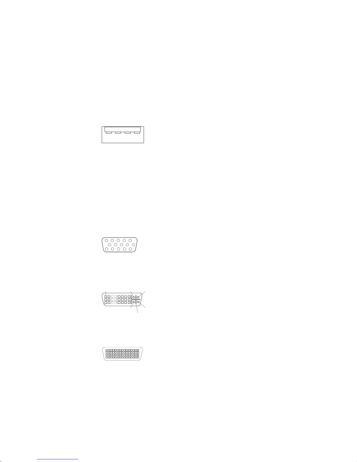
Universal Serial Bus connectors
There are eight USB 2.0 connectors, two on the front and six on the rear of the
computer. Use the USB connectors to connect optional devices, such as telephony,
storage and multimedia devices. USB 2.0 technology transfers data at up to 480 Mb
per second (Mbps) with a maximum of 127 external devices and a maximum signal
distance of 5 meters (16 ft) per segment (if the device that is attached to the
computer is a USB 2.0 device). If multiple USB devices are attached to the
computer, the USB hub must be USB 2.0; otherwise, all USB 2.0 devices will
transfer data at 12 Mbps. Using Plug and Play technology, USB devices are
configured automatically. The following illustration shows a USB connector.
14
Use a 4-pin USB cable to connect an external device to a USB connector.
Video connector
The PCI Express x16 adapter (slot 2) provides the video connector. This connector
is on the rear of the computer. Use the video connector to connect a monitor or
other display device. The following illustrations show examples of different video
connectors.
Analog video connector
5
1
1115
Digital (DVI-I) video connector
1
C1 C2
C3C5C4
Dual monitor system-59 (DMS-59) video connector
Chapter 4. Customer replacement units 65
Page 76

Some models come with a digital video interface (DVI) connector for connecting a
digital monitor. If you have problems viewing information with a second monitor, see
the IBM IntelliStation User’s Guide on the IBM IntelliStation Documentation CD.
Models with the NVIDIA Quadro FX 1300 or NVIDIA Quadro FX 3400 video adapter
come with a DVI-I to VGA style analog converter for each DVI-I connector.
Important: To get the best performance from the NVIDIA Quadro FX 3400 video
adapter, you must connect the video adapter to the computer power
supply. Otherwise, the video adapter will be operating with very limited
power, resulting in a decrease in performance for some applications.
Use the PCI Express x16 external power drop to connect the video
adapter to the computer power supply. The following illustration shows
the location of the video adapter power connector.
Video adapter
power connector
Models with the NVIDIA Quadro NVS 280 video adapter come with a dual monitor
system-59 (DMS-59) to dual-analog monitor pigtail cable. If you want to set up two
digital monitors, you must purchase a separate dual-digital monitor cable.
66 IntelliStation M Pro Types 6225 and 6228: Hardware Maintenance Manual and Troubleshooting Guide
Page 77

Chapter 5. Field replaceable units
Microprocessor and heat sink . . . . . . . . . . . . . . . . . . .68
Rotating the internal drive cage . . . . . . . . . . . . . . . . . . .73
Power supply . . . . . . . . . . . . . . . . . . . . . . . . .74
Power switch/LED assembly . . . . . . . . . . . . . . . . . . . .76
System board . . . . . . . . . . . . . . . . . . . . . . . . .77
System board option connectors . . . . . . . . . . . . . . . . .77
System board internal connectors . . . . . . . . . . . . . . . . .78
System board external connectors . . . . . . . . . . . . . . . . .79
System board error LEDs . . . . . . . . . . . . . . . . . . . .79
System board jumpers . . . . . . . . . . . . . . . . . . . . .80
Removing the system board . . . . . . . . . . . . . . . . . . .81
The following information describes procedures for removing and installing certain
components inside the system. Only a qualified service technician is authorized to
replace the components described in this section.
Important: The field replaceable unit (FRU) procedures are intended for trained
servicers who are familiar with IBM xSeries products. See the parts
listing in “System replaceable units” on page 107 to determine if the
component being replaced is a customer replaceable unit (CRU) or a
FRU.
Before servicing this system, read “Installation guidelines” on page 29 and
Note:
Appendix B, “Safety information,” on page 115.
© Copyright IBM Corp. 2004 67
Page 78

Microprocessor and heat sink
Each new microprocessor includes a new heat sink and vacuum tool for handling
the microprocessor. The new heat sink must be installed when replacing the
microprocessor. If you use the old heat sink with the new microprocessor, the
computer might over heat.
Before you begin:
v Read the “Installation guidelines” on page 29.
v Read Appendix B, “Safety information,” on page 115.
v Review the information in “System reliability guidelines” on page 29.
remove the microprocessor and heat sink, complete the following steps.
To
CAUTION:
Turn off the computer at least one hour before removing the microprocessor.
This allows the heat sink, and the thermal material between the
microprocessor and the heat sink to cool down.
1. Turn off the computer, if it is on.
2. Disconnect the power cord from the power source and from the computer;
then, disconnect all external cables.
3. Lay the computer on its side.
4. Remove the side cover (see “Removing the side cover” on page 32).
5. Remove the microprocessor fan assembly (see “Removing and replacing the
microprocessor fan assembly” on page 35).
Important: When disconnecting cables, note the cable routing and connector
labels for use during installation.
6. Disconnect any cables that impede access to the microprocessor.
68 IntelliStation M Pro Types 6225 and 6228: Hardware Maintenance Manual and Troubleshooting Guide
Page 79

Attention: The heat-sink retention lever is spring-loaded when the heat sink
is in place. Releasing the lever too quickly or allowing it to spring upward can
damage the heat sink and surrounding components.
7. Remove the heat sink from the microprocessor:
a. Release the heat-sink retention lever by pressing down on the end, moving
it to the left and slowly releasing it to the open (up) position.
Orientation
key
Retention lever
Important: Be careful when handling the microprocessor and heat sink. If
the microprocessor and heat sink will be reused, do not
contaminate the thermal material between them.
b. Tip the top of the heat sink up (away from the system board) while sliding it
away from the lower flange of the retention module; then, remove it from
the computer. After removal, place the heat sink on its side on a clean, flat
surface.
Note: The heat sink is keyed to a 45-degree angle in one corner of the
retention module to maintain proper orientation during installation.
Chapter 5. Field replaceable units 69
Page 80

Attention: The microprocessor socket lever is spring-loaded when the
microprocessor is in place. Releasing the lever too quickly or allowing it to
spring upward can damage the microprocessor and surrounding components.
8. Release the microprocessor socket lever by pressing down on the end, moving
it to the right, and slowly releasing it to the open (up) position.
Socket cover
9. Open the microprocessor socket cover by lifting up the tab on the top edge.
Lever
70 IntelliStation M Pro Types 6225 and 6228: Hardware Maintenance Manual and Troubleshooting Guide
Page 81
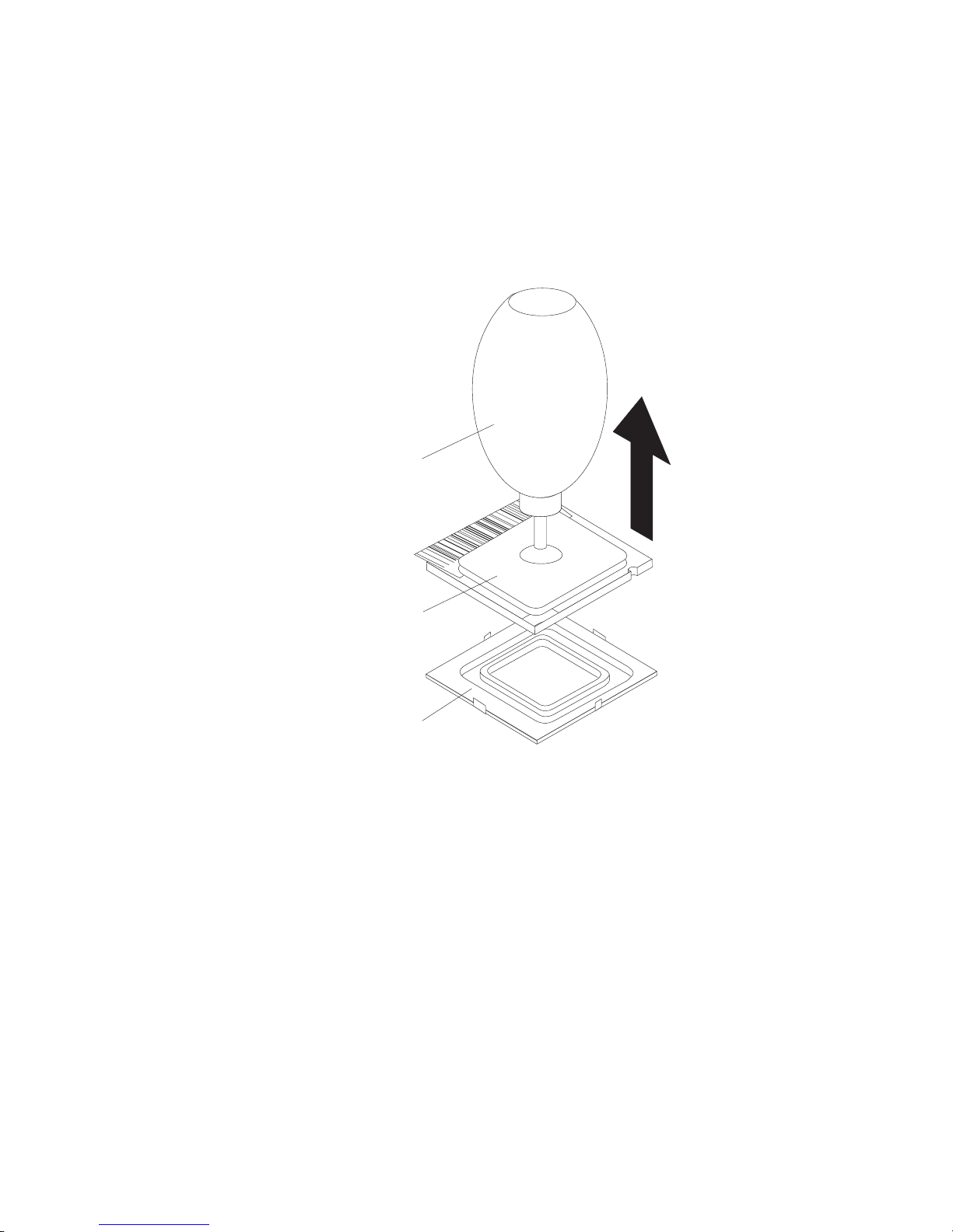
Attention: Use the vacuum tool provided with the replacement part to
remove the microprocessor. Dropping the microprocessor during removal can
damage the contacts. Also, contaminants on the microprocessor contacts, such
as oil from your skin, can cause connection failures between the contacts and
the socket.
10. Remove the microprocessor using the vacuum tool and the following
procedure:
a. Squeeze and hold the bladder of the tool; then, place the suction cup on
the microprocessor and release the bladder.
Vacuum tool
Microprocessor
Socket
b. Using the tool, carefully lift the microprocessor straight up and out of the
socket, and place it on a static-protective surface.
c. Squeeze the bladder of the tool to release the microprocessor from the
suction cup.
Chapter 5. Field replaceable units 71
Page 82

To replace the microprocessor and heat sink, reverse the previous steps.
Note: To maintain proper orientation between the microprocessor and the
microprocessor socket during installation, observe the following:
v The microprocessor has two notches that are keyed to two tabs on the
sides of the socket.
v A triangle-shaped indicator on one corner of the microprocessor points to
a 45-degree angle on one corner of the socket.
Microprocessor
Orientation
notches
Orientation
indicator
72 IntelliStation M Pro Types 6225 and 6228: Hardware Maintenance Manual and Troubleshooting Guide
Page 83
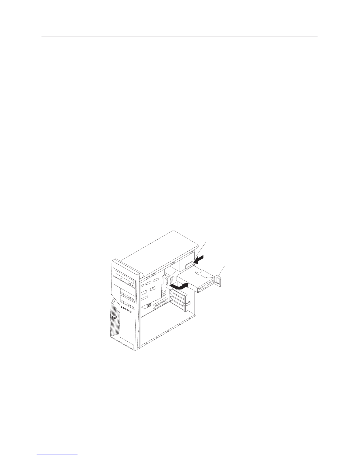
Rotating the internal drive cage
When you are performing some procedures, it might be easier or necessary to
rotate the internal drive cage (bay 5) out of the computer. The drive-cage retention
latch locks the cage into position inside the computer and outside the computer.
Before you begin:
v Read the “Installation guidelines” on page 29.
v Read Appendix B, “Safety information,” on page 115.
v Review the information in “System reliability guidelines” on page 29.
rotate the internal drive cage, complete the following steps:
To
1. Turn off the computer, if it is on.
2. Disconnect the power cord from the power source and from the computer; then,
disconnect all external cables.
3. Remove the side cover (see “Removing the side cover” on page 32).
4. Stand the computer upright if it is lying on its side.
5. Push the drive-cage retention latch toward the front of the computer and hold
the latch in place.
Important: As you rotate the drive cage, make sure the hard disk drive cables
or other internal cables do not impede the rotation of the drive
cage.
6. Grasp the drive-cage handle and rotate the cage until it locks into the
drive-cage retention latch.
Drive-cage
retention latch
Drive-cage
handle
Chapter 5. Field replaceable units 73
Page 84

Power supply
Before you begin:
v Read the “Installation guidelines” on page 29.
v Read Appendix B, “Safety information,” on page 115.
v Review the information in “System reliability guidelines” on page 29.
remove the power supply, complete the following steps:
To
1. Turn off the computer, if it is on.
2. Disconnect the power cord from the power source and from the computer;
then, disconnect all external cables.
3. Lay the computer on its left side.
4. Remove the cover (see “Removing the side cover” on page 32).
5. Rotate the internal drive cage out of the computer (see “Rotating the internal
drive cage” on page 73).
Important: When disconnecting cables, note the cable routing and connector
labels for use during installation.
6. Disconnect the cables from the power supply to the system board and all
internal components.
Note: To provide extra space for the power supply removal, it might be helpful
to perform the following steps:
v Slide the drives in bay 1 and bay 2 (if installed) forward slightly (see
“Removing and replacing the CD-ROM or CD-RW drive” on page 45
for more information). It is not necessary to remove these drives.
v Disconnect the IEEE 1394 (Firewire) cable from the system board
(see “System board external connectors” on page 79 for the location
of the internal 1394 connector).
7. Push the internal drive-cage retention latch toward the front of the computer;
then, grasp the drive-cage handle and carefully rotate the cage until it rests on
the back panel of the computer.
74 IntelliStation M Pro Types 6225 and 6228: Hardware Maintenance Manual and Troubleshooting Guide
Page 85

8. Remove the power-supply retaining screws from the rear of the computer.
9. Press in on the power-supply retaining tab and slide the power supply toward
the front of the computer until it clears the mounting bracket.
10. Carefully lift the power supply out of the computer.
To replace the power supply, reverse the previous steps.
Chapter 5. Field replaceable units 75
Page 86

Power switch/LED assembly
Before you begin:
v Read the “Installation guidelines” on page 29.
v Read Appendix B, “Safety information,” on page 115.
v Review the information in “System reliability guidelines” on page 29.
To remove the power switch/LED assembly, complete the following steps:
1. Turn off the computer, if it is on.
2. Disconnect the power cord from the power source and from the computer; then,
disconnect all external cables.
3. Remove the side cover (see “Removing the side cover” on page 32).
4. Remove the front bezel (see “Removing and Installing the Bezel” on page 34).
5. Lay the computer on its left side.
6. Remove the microprocessor fan assembly (see “Removing and replacing the
microprocessor fan assembly” on page 35).
Important: When disconnecting cables, note the cable routing and connector
labels for use during installation.
7. Disconnect the LED cables from the system board and front I/O panel.
8. From the front of the computer, press the assembly retaining tab to the right and
through the opening in the front panel; then, carefully lift the assembly out of the
computer from the inside.
Retaining tab
To replace the power switch/LED assembly, reverse the previous steps.
76 IntelliStation M Pro Types 6225 and 6228: Hardware Maintenance Manual and Troubleshooting Guide
Page 87

System board
This section contains service information for the system board.
System board option connectors
The following illustration shows the system board connectors for user-installable
options.
Diskette drive
(optional)
DIMM 4
DIMM 3
DIMM 2
DIMM 1
Slot 1, PCI Express x1
Slot 2, PCI Express x16
Slot 3, PCI
Slot 4, PCI
Chapter 5. Field replaceable units 77
Page 88

System board internal connectors
The following illustration shows the internal connectors on the system board.
Microprocessor power
Front panel switch / LEDs
CD audio
System error
LED (front)
Internal speaker
Ethernet activity
LED (front)
SATA drive 4
SATA drive 3
Microprocessor
Battery
SCSI adapter
(mini-PCI)
Fan
Microprocessor fan
IEEE 1394 (Firewire)
enable / disable jumper
Boot block jumper
SCSI LED
SATA drive 2
SATA drive 1
IDE drive
Main power
Clear CMOS jumper
Intrusion switch
78 IntelliStation M Pro Types 6225 and 6228: Hardware Maintenance Manual and Troubleshooting Guide
Page 89

System board external connectors
The following illustration shows the external input/output port connectors on the
system board.
Internal 1394 (FireWire)
External 1394 (FireWire)
Audio in / out
Serial 2
Parallel
Serial 1
Keyboard / mouse
USBs (4)
USBs (2) /
Ethernet
System board error LEDs
The following illustration shows the LEDs on the system board.
DIMM 4 error LED
DIMM 3 error LED
DIMM 2 error LED
DIMM 1 error LED
Microprocessor
fan error LED
System error LED
Rear fan error
LED
Chapter 5. Field replaceable units 79
Page 90
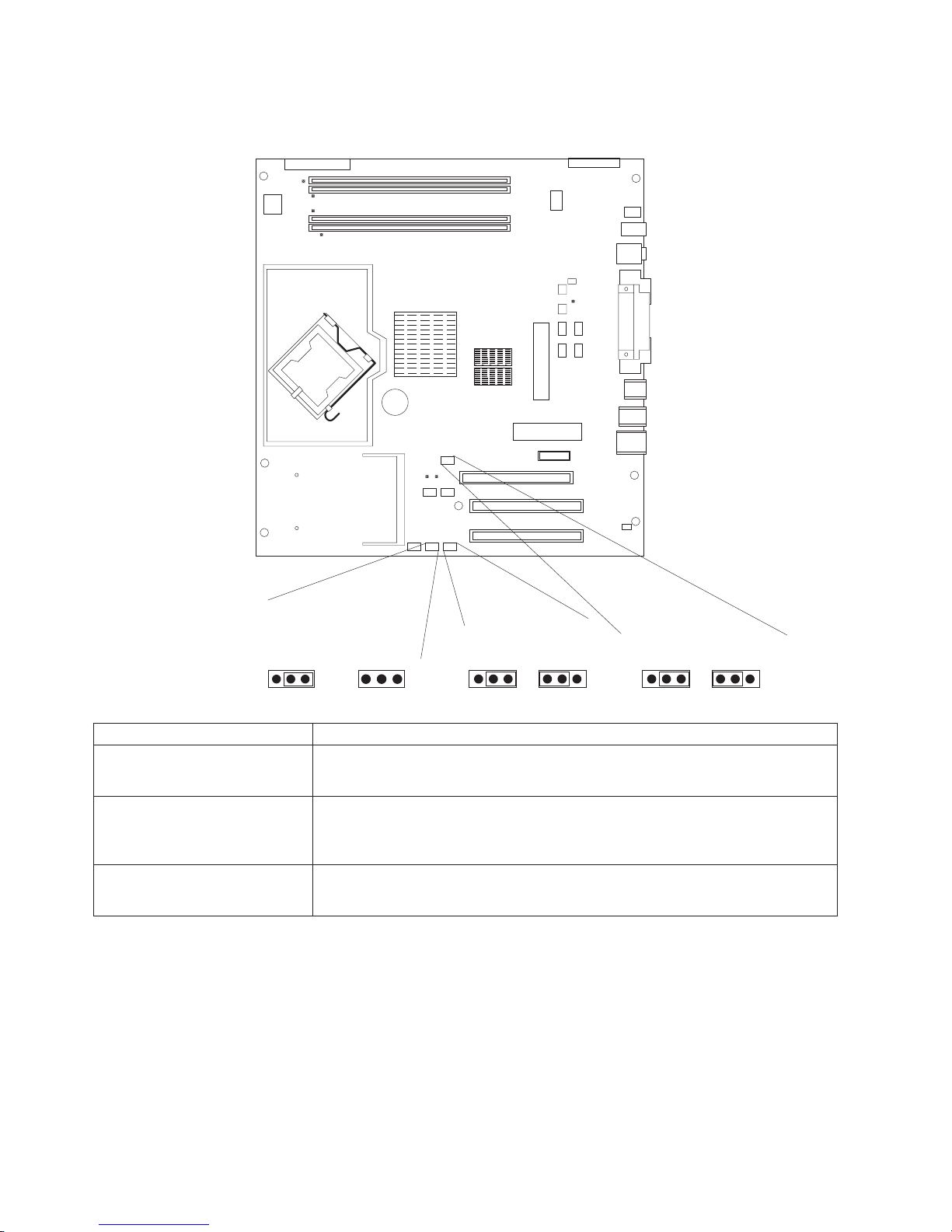
System board jumpers
This section describes the jumpers on the system board.
(pins 1 and 2)
Jumper Settings
Boot block (J1)
Clear CMOS (JBAT1)
IEEE 1394, Firewire (J1394)
Boot Block Jumper (J1)
Boot Block
Default
(Recover)
(No Jumper)
3 2 1
v Normal (default) (jumper on pins 1 and 2)
v Boot block recovery (no jumper)
v Keep CMOS data (default) (jumper on pins 1 and 2)
v Clear CMOS data (jumper on pins 2 and 3 with power cords removed from
computer)
v IEEE 1394 enabled (default) (jumper on pins 1 and 2)
v IEEE 1394 disabled (jumper on pins 2 and 3)
3 2 1
IEEE 1394 ( Firewire )
enable / disable jumper
DisableDefault
3 2 13 2 1
Clear CMOS Jumper (JBAT1)
RecoverDefault
3 2 13 2 1
80 IntelliStation M Pro Types 6225 and 6228: Hardware Maintenance Manual and Troubleshooting Guide
Page 91

Removing the system board
Before you begin:
v Read “Installation guidelines” on page 29.
v Read Appendix B, “Safety information,” on page 115.
v Review the information in “System reliability guidelines” on page 29.
When replacing the system board, you must either update the computer with
Note:
the latest firmware or restore the pre-existing firmware that the customer
provides on a diskette or CD image.
To remove the system board, complete the following steps:
1. Turn off the computer, if it is on.
2. Disconnect the power cord from the power source and from the computer;
then, disconnect all external cables.
3. Lay the computer on its left side.
4. Remove the side cover (see “Removing the side cover” on page 32).
5. Remove the microprocessor fan assembly (see “Removing and replacing the
microprocessor fan assembly” on page 35).
Important: When disconnecting cables, note the cable routing and connector
labels for use during installation.
6. Disconnect the cables.
Note: Installed adapters might have to be removed before some cables can
be disconnected.
7. Remove any installed adapters (see “Installing an adapter” on page 39).
8. Remove the SCSI daughter card, if one is installed (see “Removing and
replacing the SCSI daughter card” on page 37).
9. Remove the microprocessor and heat sink (see “Microprocessor and heat sink”
on page 68).
10. Remove memory modules (see “Installing memory modules” on page 54).
11. Remove the battery (see “Replacing the battery” on page 57).
12. Remove the seven screws that secure the system board.
Chapter 5. Field replaceable units 81
Page 92

System board
screws (7 places)
13. Slide the system board toward the front of the computer to disengage it from
the slots on the computer chassis; then, lift the system board out of the
computer.
To replace the system board, reverse the previous steps.
82 IntelliStation M Pro Types 6225 and 6228: Hardware Maintenance Manual and Troubleshooting Guide
Page 93

Chapter 6. Symptom-to-FRU index
This index supports the IntelliStation M Pro computer.
The symptom-to-FRU index lists symptoms, errors, and the possible causes. The
most likely cause is listed first. Use this symptom-to-FRU index to help you decide
which FRUs to have available when servicing the computer.
The first column in each table in this index lists error codes or messages, and the
final column lists one or more suggested actions or FRUs to replace. Take the
action (or replace the FRU) suggested first in the list of the entries in the final
column, and then restart the computer to see if the problem has been corrected.
Notes:
1. Check the configuration before you replace a FRU. Configuration problems can
cause false errors and symptoms.
2. For IBM devices not supported by this index, see the manual for that device.
3. Always start with “General checkout” on page 9
4. Try reseating a suspected component or reconnecting a cable before replacing
the component.
The POST BIOS code displays POST error codes and messages on the screen.
Beep symptoms
Beep symptoms are short tones or a series of short tones separated by pauses
(intervals without sound). See the examples in the following table.
Beeps Description
1-2-3
4 Four continuous beeps
One beep after successfully completing POST indicates that the computer is
functioning correctly.
Beep/symptom FRU/action
1-1-3
(CMOS write/read test failed.)
1-1-4
(BIOS EEPROM checksum failed.)
1-2-1
(Programmable Interval Timer failed.)
1-2-2
(DMA initialization failed.)
v One beep
v A pause (or break)
v Two beeps
v A pause (or break)
v Three beeps
1. Battery
2. System board
1. Recover BIOS code.
2. System board.
System board
System board
© Copyright IBM Corp. 2004 83
Page 94

Beep/symptom FRU/action
1-2-3
System board
(DMA page register write/read
failed.)
1-3-1
(First 64K RAM test failed.)
2-1-1
1. DIMM
2. System board
System board
(Secondary DMA register failed.)
2-1-2
System board
(Primary DMA register failed.)
2-1-3
System board
(Primary interrupt mask register
failed.)
2-1-4
System board
(Secondary interrupt mask register
failed)
2-2-2
(Keyboard controller failed.)
2-2-3
(CMOS power failure and checksum
checks failed)
2-4-1
1. Keyboard
2. System board
1. Battery
2. System board
Video card
(Video failed; screen believed
operable.)
3-1-1
System board
(Timer tick interrupt failed.)
3-1-2
System board
(Interval timer channel 2 failed.)
3-1-3
(RAM test failed above address
OFFFFH.)
3-1-4
(Time-Of-Day clock failed.)
3-2-1
1. DIMM
2. System board
1. Battery
2. System board
System board
(Serial port failed.)
3-2-2
System board
(Parallel port failed.)
3-3-1
(Memory size mismatch occurred.)
1. DIMM
2. System board
3. Battery
3-3-2
(Critical SMBUS error occurred, I2C
error.)
1. Disconnect the computer power cord from outlet, wait 30 seconds,
and retry.
2. System board.
3. Microprocessor.
4. DIMMs.
3-3-3
(No operational memory in system.)
1. Install or reseat the memory modules, and then do a 3-boot reset.
2. DIMMs.
3. System board.
84 IntelliStation M Pro Types 6225 and 6228: Hardware Maintenance Manual and Troubleshooting Guide
Page 95

No-beep symptoms
No-beep symptom FRU/action
No beep occurs during POST. System board
No beep, no video, and the
System board
system attention LED (if
present) is off.
No beep, no video, and the
See “Undetermined problems” on page 102
system attention LED (if
supported) is on.
BIST failed. Microprocessor
Diagnostic error codes
Note: In the following error codes, if XXX is 000, 195, or 197, do not replace a
FRU. The description for these error codes are:
000 The test passed.
195 The Esc key was pressed to stop the test.
197 Warning; a hardware failure might not have occurred.
all error codes, replace the FRU or take the action indicated.
For
Error code/symptom FRU/action
001-XXX-000
(Failed core tests)
001-XXX-001
(Failed core tests)
001-250-000
(Failed system board ECC)
001-250-001
(Failed system board ECC)
005-XXX-000
(Failed video test)
011-XXX-000
(Failed COM1 serial port test)
011-XXX-001
(Failed COM2 serial port test)
014-XXX-000
(Failed parallel port test)
015-XXX-001
(USB interface not found, board damaged)
015-XXX-198
(USB device connected during USB test.)
System board
System board
System board
System board
1. Video adapter (if installed)
2. System board
1. Check loopback plug connected to externalized serial port.
2. System board.
1. Check loopback plug connected to externalized serial port.
2. System board.
System board
System board
1. Remove USB devices from USB1, USB2, USB3, USB4, USB5,
and USB6; then, run the USB interface test again.
2. System board.
Chapter 6. Symptom-to-FRU index 85
Page 96

Error code/symptom FRU/action
020-XXX-000
System board
(Failed PCI interface test.)
030-XXX-00N
If N=0, system board; if N>0, SCSI adapter in slot N.
(Failed SCSI interface test.)
035-XXX-099
If adapter is installed re-check connection.
(No adapters were found.)
035-XXX-S99
(Failed RAID test on PCI slot S. S =
number of failing PCI slot.)
1. RAID adapter
2. Cable
3. System board
035-XXX-SNN
Hard disk drive with SCSI ID nn on RAID adapter in PCI slot s
(s = number of failing PCI slot, nn = SCSI
ID of failing fixed disk.)
035-253-S99
(RAID adapter initialization failure.)
1. ServeRAID™ adapter in slot s is not configured properly. Obtain
the basic and extended configuration status and see the ServeRAID
Hardware Maintenance Manual for more information.
2. Cable.
3. Adapter.
089-XXX-001
(Failed microprocessor test.)
1. Verify microprocessor 1 is installed an seated correctly.
2. Verify BIOS code is at latest level.
3. Microprocessor 1.
4. System board.
089-XXX-002
(Failed optional microprocessor test.)
1. Verify microprocessor 2 is installed an seated correctly.
2. Verify BIOS code is at latest level.
3. Microprocessor 2.
4. System board.
201-XXX-0NN
(Failed memory test.)
1. DIMM Location slots 1-2 where nn = DIMM location
Note: nn 1=DIMM 1; 2=DIMM 2
2. System board
201-XXX-999
(Multiple DIMM failure, see error text.)
202-XXX-001
(Failed system cache test.)
1. See error text for failing DIMMs.
2. System board.
1. Verify microprocessor 1 is installed and seated correctly.
2. Verify BIOS code is at latest level.
3. Microprocessor 1.
4. System board.
202-XXX-002
(Failed system cache test.)
1. Verify microprocessor 2 is installed and seated correctly.
2. Verify BIOS code is at latest level.
3. Microprocessor 2.
4. System board.
206-XXX-000
(Failed diskette drive test.)
1. Try test with another diskette.
2. Cable.
3. Diskette drive.
4. System board.
86 IntelliStation M Pro Types 6225 and 6228: Hardware Maintenance Manual and Troubleshooting Guide
Page 97

Error code/symptom FRU/action
215-XXX-000
(Failed IDE CD-ROM drive test.)
1. Try test with another CD-ROM.
2. CD-ROM drive cables.
3. CD-ROM drive.
4. System board.
217-198-XXX
(Could not establish drive parameters.)
1. Check cable and termination.
2. SCSI backplane.
3. Hard disk.
217-XXX-000
(Failed BIOS hard disk test)
Note: If RAID is configured, the hard disk
1. Fixed disk 1 (hard disk drive 1)
2. System board
number refers to the RAID logical array.
217-XXX-001
(Failed BIOS hard disk test)
Note: If RAID is configured, the hard disk
1. Fixed disk 2 (hard disk drive 2)
2. System board
number refers to the RAID logical array.
301-XXX-000
(Failed keyboard test.)
302-XXX-000
(Failed mouse test.)
405-XXX-000
(Failed Ethernet test on controller on the
system board.)
405-XXX-00N
(Failed Ethernet test on adapter in PCI slot
n.)
1. Keyboard
2. System board
1. Mouse
2. System board
1. Verify that Ethernet is not disabled in BIOS.
2. System board.
1. For n=0, system board
2. For n>0, adapter in PCI slot n
3. System board
415-XXX-000
(Failed Modem test.)
1. Cable
Note: Ensure modem is present and attached to computer.
2. Modem
3. System board
Error symptoms
You can use the error-symptom tables to find solutions to problems that have
definite symptoms.
If you cannot find the problem in the error symptom charts, go to “Starting the
diagnostic programs and viewing the test log” on page 13 to test the computer.
If you have just added new software or a new option and the computer is not
working, complete the following steps before using the error symptom charts:
1. Remove the software or device that you just added.
2. Run the diagnostic tests to determine whether the computer is running correctly.
3. Reinstall the new software or new device.
the following table, if the entry in the FRU/action column is a suggested action,
In
perform that action; if it is the name of a component, reseat the component and
replace it if necessary. The most likely cause of the symptom is listed first.
Chapter 6. Symptom-to-FRU index 87
Page 98

CD-ROM drive problems
Symptom FRU/action
The CD-ROM drive is not
recognized.
1. Make sure that:
v The IDE channel to which the CD-ROM drive is attached (primary or
secondary) is enabled in the Configuration/Setup Utility program.
v All cables and jumpers are installed correctly.
v The correct device driver is installed for the CD-ROM drive.
2.
Run CD-ROM drive diagnostics.
3. CD-ROM drive.
The CD is not working correctly.
1. Clean the CD.
2. Run CD-ROM drive diagnostics.
3. CD-ROM drive.
The CD-ROM drive tray is not
working. (The computer must be
turned on.)
1. Insert the end of a straightened paper clip into the manual tray-release
opening.
2. Run CD-ROM drive diagnostics.
3. CD-ROM drive.
Diskette drive problems
Symptom FRU/action
The diskette drive activity LED
stays lit, or the computer
bypasses the diskette drive.
1. If there is a diskette in the drive, make sure that:
v The diskette drive is enabled in the Configuration/Setup utility program.
v The diskette is good and not damaged. (Try another diskette if you have
one.)
v The diskette is inserted correctly in the drive.
v The diskette contains the necessary files to start the computer.
v The software program is working properly.
v The cable is installed correctly (in the proper orientation).
To prevent diskette drive read/write errors, make sure that the distance
2.
between monitors and diskette drives is at least 76 mm (3 in.).
3. Run diskette drive diagnostics.
4. Cable.
5. Diskette drive.
6. System board.
General problems
Symptom FRU/action
A cover lock is broken, an LED
Broken CRU/FRU
is not working, or a similar
problem has occurred
88 IntelliStation M Pro Types 6225 and 6228: Hardware Maintenance Manual and Troubleshooting Guide
Page 99

Hard disk drive problems
Symptom FRU/action
Not all drives are recognized by
the hard disk drive diagnostic
test (the Fixed Disk test).
1. Remove the first drive not recognized and try the hard disk drive
diagnostic test again.
2. If the remaining drives are recognized, replace the drive that you removed with
a new one.
The computer stops responding
during hard disk drive diagnostic
test.
1. Remove the hard disk drive being tested when the computer stopped
responding and try the diagnostic test again.
2. If the hard disk drive diagnostic test runs successfully, replace the drive you
removed with a new one.
A hard disk drive passes the
diagnostic Fixed Disk Test but
the problem remains.
Run the diagnostic SCSI Fixed Disk Test (see “Starting the diagnostic programs
and viewing the test log” on page 13.
Note: This test is not available on servers that have RAID arrays or servers that
have IDE or SATA hard disk drives.
IEEE 1394 (firewire) port problems
Symptom FRU/action
An IEEE 1394 device does not
work.
Make sure that:
v The correct IEEE 1394 device driver is installed.
v The operating system supports IEEE 1394 devices.
Intermittent problems
Symptom FRU/action
A problem occurs only
occasionally and is difficult to
detect.
1. Make sure that:
v All cables and cords are connected securely to the rear of the computer and
attached options.
v When the computer is turned on, air is flowing from the rear of the computer
at the fan grille. If there is no airflow, the fan is not working. This causes the
computer to overheat and shut down.
v The SCSI bus and devices are configured correctly and the last external
device in each SCSI chain is terminated correctly.
Check the system-error log.
2.
Keyboard, mouse, or pointing-device problems
Symptom FRU/action
All or some keys on the
keyboard do not work.
1. Make sure that:
v The keyboard cable is securely connected to the computer, and the
keyboard and mouse cables are not reversed.
v The computer and the monitor are turned on.
Keyboard.
2.
3. System board.
The mouse or pointing device
does not work.
1. Make sure that:
v The mouse or pointing-device cable is securely connected to the computer,
and the keyboard and mouse cables are not reversed.
v The mouse device drivers are installed correctly.
v Both the computer and the monitor are turned on.
Mouse or pointing device.
2.
3. System board.
Chapter 6. Symptom-to-FRU index 89
Page 100

Memory problems
Symptom FRU/action
The amount of system memory
displayed is less than the
amount of physical memory
installed.
1. Make sure that:
v The memory modules are seated correctly.
v You have installed the correct type of memory.
v If you changed the memory, you updated the memory configuration in the
Configuration/Setup Utility program.
v All banks of memory are enabled. The computer might have automatically
disabled a memory bank when it detected a problem, or a memory bank
might have been manually disabled.
Check POST error log for error message 289:
2.
v If the DIMM was disabled by a system-management interrupt (SMI), replace
the DIMM.
v If the DIMM was disabled by the user or by POST, run the
Configuration/Setup Utility program and enable the DIMM.
DIMM.
3.
4. System board.
Microprocessor problems
Symptom FRU/action
The computer emits a
continuous tone during POST.
(The startup (boot)
1. Verify that the microprocessor is seated properly.
2. Microprocessor.
microprocessor is not working
correctly.)
Monitor problems
Symptom FRU/action
Testing the monitor. See the information that comes with the monitor for adjusting and testing
instructions. (Some IBM monitors have their own self-tests.)
90 IntelliStation M Pro Types 6225 and 6228: Hardware Maintenance Manual and Troubleshooting Guide
 Loading...