

Page 1
®
®
IntelliStation E Pro
Types 6204 and 6214
User’s Guide
Welcome. . .
Thank you for buying an IBM
IntelliStation E Pro computer.
Set up the computer
This contains
User’s Guide
information for setting up,
installing options, and preparing
applications to run on your
computer. This book also contains
information regarding everyday
use and solving problems.
You can find the most current
information about your computer
at http://www.ibm.com/pc/support/
on the IBM Web site.
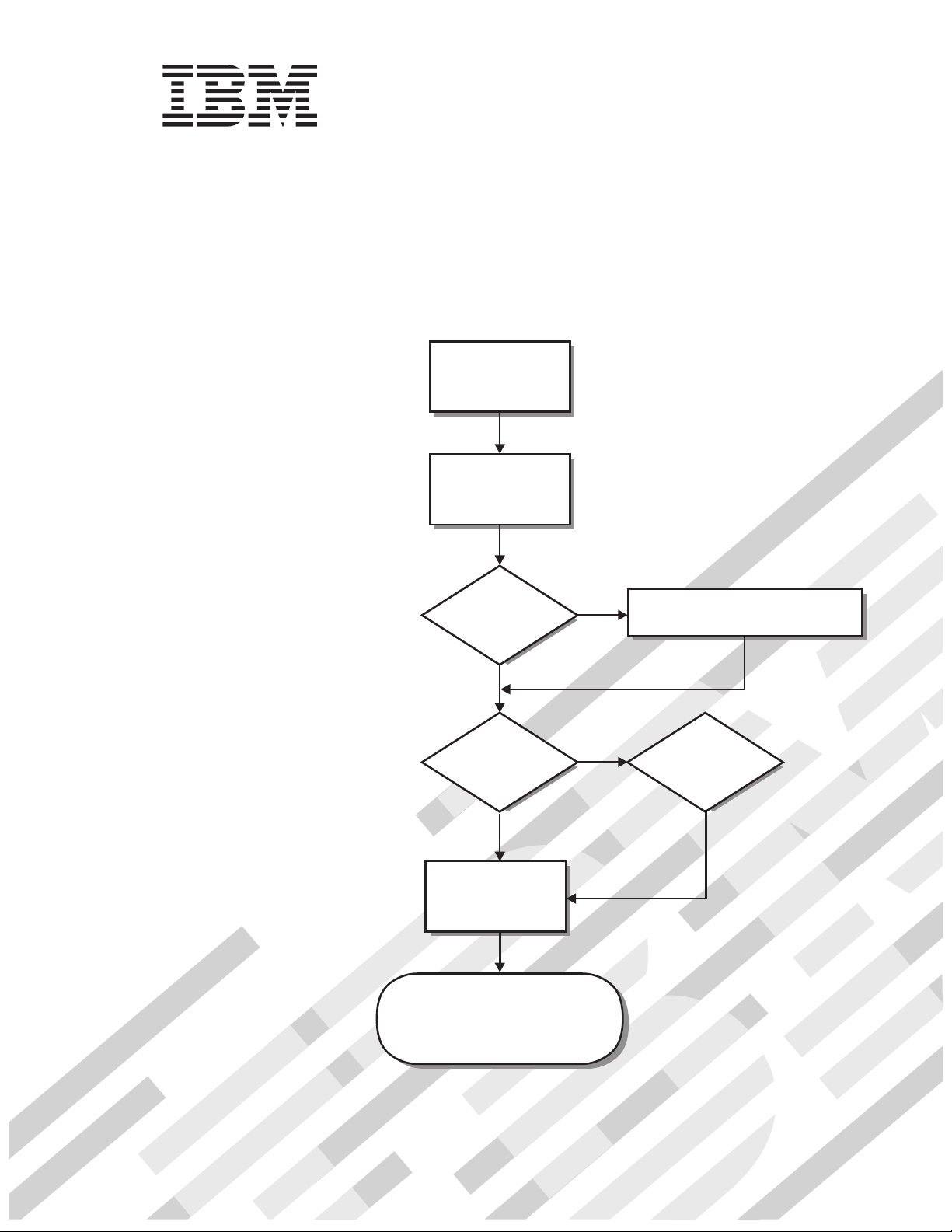
Start the computer
Did the computer
start correctly?
Ye s
Do you plan to
use Windows 2000 or
Windows XP?
Complete the setup
program
No
No
Go to the Solving Problems
chapter
Install another
operating system
System is ready to use.
• Use on your to register
Access IBM
your computer
• Install options and applications
Page 2
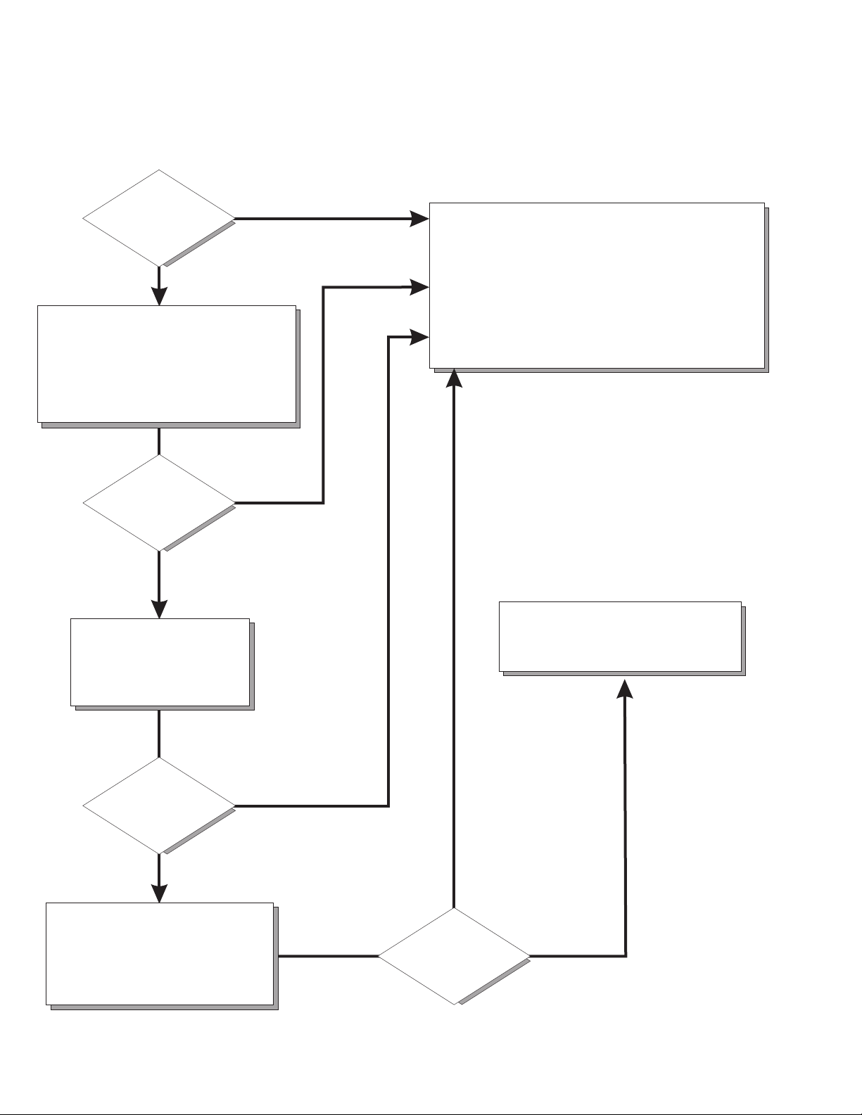
Computer Support
Computer working
properly?
Ye s
No
Check all cables for loose connections
and verify that all optional devices you
installed are on the Compatibility Matrix.
You can view the Compatibility Matrix at:
http://www.ibm.com/pc/accessories/
index.html
Problem
solved?
Ye s
No
Use the troubleshooting
information provided with
your computer to determine
the cause of the problem
and the action to take.
Register and profile your computer
After you register and profile, you will be able to:
• Diagnose problems using the IBM Online Assistant
• Participate in the IBM discussion forum
• Receive e-mail notifications of technical updates
related to your profiled products
Register at:
Profile at:
http://www.ibm.com/pc/register
http://www.ibm.com/pc/support
Phone an IBM HelpCenter .
You can view the HelpCenter phone
numbers in the Support Phone list at:
http://www.ibm.com/pc/support
®
Problem
solved?
Ye s
No
Flash the latest levels of BIOS
and download the latest level of
diagnostics.You can download
this code at:
http://www.ibm.com/pc/support
Ye s
Problem
solved?
No
Page 3

IBM® IntelliStation® E Pro
User’s Guide
IBM
Page 4

First Edition (October 2001)
© Copyright International Business Machines Corporation 2000, 2001. All rights reserved.
US Government Users Restricted Rights – Use, duplication or disclosure restricted by GSA ADP Schedule Contract with
IBM Corp.
Page 5

Contents
Safety information . . . . . . . . . . . . . . . . . . . . . . . . . . . . . . . . . . . . . . . . . . . . . . . . . vii
Preface . . . . . . . . . . . . . . . . . . . . . . . . . . . . . . . . . . . . . . . . . . . . . . . . . . . . . . . . . . . xiii
Related Information . . . . . . . . . . . . . . . . . . . . . . . . . . . . . . . . . . . . . . . . . . . . . . . . . xiii
Notices and statements used in this book . . . . . . . . . . . . . . . . . . . . . . . . . . . . . . . . xiii
Chapter 1. Introducing the IntelliStation E Pro . . . . . . . . . . . . . . . . . . . . . . . . . . . 1
Features and specifications for the desktop model . . . . . . . . . . . . . . . . . . . . . . . . . . 2
Features and specifications for the tower model . . . . . . . . . . . . . . . . . . . . . . . . . . . . 3
Inventory checklist . . . . . . . . . . . . . . . . . . . . . . . . . . . . . . . . . . . . . . . . . . . . . . . . . . . 3
Software . . . . . . . . . . . . . . . . . . . . . . . . . . . . . . . . . . . . . . . . . . . . . . . . . . . . . . . . . . . 4
Preinstalled software . . . . . . . . . . . . . . . . . . . . . . . . . . . . . . . . . . . . . . . . . . . . . . . 4
Software Selections CD . . . . . . . . . . . . . . . . . . . . . . . . . . . . . . . . . . . . . . . . . . . . . 5
Other software CDs . . . . . . . . . . . . . . . . . . . . . . . . . . . . . . . . . . . . . . . . . . . . . . . . 6
What your IntelliStation E Pro computer offers . . . . . . . . . . . . . . . . . . . . . . . . . . . . . . 6
Reliability, availability, and serviceability features. . . . . . . . . . . . . . . . . . . . . . . . . . . . 7
Computer controls and indicators . . . . . . . . . . . . . . . . . . . . . . . . . . . . . . . . . . . . . . . . 8
Chapter 2. Setting up your computer . . . . . . . . . . . . . . . . . . . . . . . . . . . . . . . . . . 11
Selecting a location for your computer . . . . . . . . . . . . . . . . . . . . . . . . . . . . . . . . . . . 11
Arranging your workspace . . . . . . . . . . . . . . . . . . . . . . . . . . . . . . . . . . . . . . . . . . . . 11
Comfort. . . . . . . . . . . . . . . . . . . . . . . . . . . . . . . . . . . . . . . . . . . . . . . . . . . . . . . . . 11
Glare and lighting . . . . . . . . . . . . . . . . . . . . . . . . . . . . . . . . . . . . . . . . . . . . . . . . . 11
Air circulation . . . . . . . . . . . . . . . . . . . . . . . . . . . . . . . . . . . . . . . . . . . . . . . . . . . . 12
Electrical outlets and cable lengths . . . . . . . . . . . . . . . . . . . . . . . . . . . . . . . . . . . 12
Moving the stabilizing feet . . . . . . . . . . . . . . . . . . . . . . . . . . . . . . . . . . . . . . . . . . 12
Setting the voltage-selection switch . . . . . . . . . . . . . . . . . . . . . . . . . . . . . . . . . . . . . 13
Connecting computer cables . . . . . . . . . . . . . . . . . . . . . . . . . . . . . . . . . . . . . . . . . . 13
Recording important numbers . . . . . . . . . . . . . . . . . . . . . . . . . . . . . . . . . . . . . . . . . 15
Running the operating system setup program . . . . . . . . . . . . . . . . . . . . . . . . . . . . . 15
Registering your computer . . . . . . . . . . . . . . . . . . . . . . . . . . . . . . . . . . . . . . . . . . . . 16
Using Access IBM. . . . . . . . . . . . . . . . . . . . . . . . . . . . . . . . . . . . . . . . . . . . . . . . . . . 16
Installing other operating systems . . . . . . . . . . . . . . . . . . . . . . . . . . . . . . . . . . . . . . 17
Product Recovery Program . . . . . . . . . . . . . . . . . . . . . . . . . . . . . . . . . . . . . . . . . . . 17
Creating emergency diskettes . . . . . . . . . . . . . . . . . . . . . . . . . . . . . . . . . . . . . . . . . 17
Creating a Recovery Repair diskette . . . . . . . . . . . . . . . . . . . . . . . . . . . . . . . . . . 18
Creating a Norton AntiVirus Rescue diskette . . . . . . . . . . . . . . . . . . . . . . . . . . . . 18
Chapter 3. Operating your computer . . . . . . . . . . . . . . . . . . . . . . . . . . . . . . . . . . 19
Turning on your computer. . . . . . . . . . . . . . . . . . . . . . . . . . . . . . . . . . . . . . . . . . . . . 19
Using video features . . . . . . . . . . . . . . . . . . . . . . . . . . . . . . . . . . . . . . . . . . . . . . . . . 19
Video device drivers . . . . . . . . . . . . . . . . . . . . . . . . . . . . . . . . . . . . . . . . . . . . . . . 20
Changing monitor settings . . . . . . . . . . . . . . . . . . . . . . . . . . . . . . . . . . . . . . . . . . 20
Using audio features . . . . . . . . . . . . . . . . . . . . . . . . . . . . . . . . . . . . . . . . . . . . . . . . . 21
Line in. . . . . . . . . . . . . . . . . . . . . . . . . . . . . . . . . . . . . . . . . . . . . . . . . . . . . . . . . . 21
Line out. . . . . . . . . . . . . . . . . . . . . . . . . . . . . . . . . . . . . . . . . . . . . . . . . . . . . . . . . 21
Microphone. . . . . . . . . . . . . . . . . . . . . . . . . . . . . . . . . . . . . . . . . . . . . . . . . . . . . . 21
Managing your computer on a network . . . . . . . . . . . . . . . . . . . . . . . . . . . . . . . . . . 21
Wake on LAN . . . . . . . . . . . . . . . . . . . . . . . . . . . . . . . . . . . . . . . . . . . . . . . . . . . . 21
Intel Boot Agent . . . . . . . . . . . . . . . . . . . . . . . . . . . . . . . . . . . . . . . . . . . . . . . . . . 22
LANClient Control Manager (LCCM) . . . . . . . . . . . . . . . . . . . . . . . . . . . . . . . . . . 22
System Migration Assistant . . . . . . . . . . . . . . . . . . . . . . . . . . . . . . . . . . . . . . . . . 22
Desktop Management Interface . . . . . . . . . . . . . . . . . . . . . . . . . . . . . . . . . . . . . . 22
Using security features . . . . . . . . . . . . . . . . . . . . . . . . . . . . . . . . . . . . . . . . . . . . . . . 22
© Copyright IBM Corp. 2000, 2001 iii
Page 6

Anti-intrusion features . . . . . . . . . . . . . . . . . . . . . . . . . . . . . . . . . . . . . . . . . . . . . 22
Component protection . . . . . . . . . . . . . . . . . . . . . . . . . . . . . . . . . . . . . . . . . . . . . 23
Data protection. . . . . . . . . . . . . . . . . . . . . . . . . . . . . . . . . . . . . . . . . . . . . . . . . . . 23
Locking the keyboard . . . . . . . . . . . . . . . . . . . . . . . . . . . . . . . . . . . . . . . . . . . . . . 23
Shutting down your operating system . . . . . . . . . . . . . . . . . . . . . . . . . . . . . . . . . . . 24
Turning off your computer. . . . . . . . . . . . . . . . . . . . . . . . . . . . . . . . . . . . . . . . . . . . . 24
Chapter 4. Configuring your computer . . . . . . . . . . . . . . . . . . . . . . . . . . . . . . . . 27
Using the IBM Setup Utility program . . . . . . . . . . . . . . . . . . . . . . . . . . . . . . . . . . . . 27
Starting the IBM Setup Utility program . . . . . . . . . . . . . . . . . . . . . . . . . . . . . . . . 27
IBM Setup Utility main menu choices. . . . . . . . . . . . . . . . . . . . . . . . . . . . . . . . . . 28
Using the SCSISelect Utility program (some models) . . . . . . . . . . . . . . . . . . . . . . . 32
Starting the SCSISelect Utility program . . . . . . . . . . . . . . . . . . . . . . . . . . . . . . . . 32
SCSISelect menu choices . . . . . . . . . . . . . . . . . . . . . . . . . . . . . . . . . . . . . . . . . . 32
Using the Intel Boot Agent Utility program . . . . . . . . . . . . . . . . . . . . . . . . . . . . . . . . 33
Starting the Intel Boot Agent Utility program . . . . . . . . . . . . . . . . . . . . . . . . . . . . 34
Intel Boot Agent Utility menu choices. . . . . . . . . . . . . . . . . . . . . . . . . . . . . . . . . . 34
Chapter 5. Installing options . . . . . . . . . . . . . . . . . . . . . . . . . . . . . . . . . . . . . . . . . 37
Before you begin . . . . . . . . . . . . . . . . . . . . . . . . . . . . . . . . . . . . . . . . . . . . . . . . . . . 37
System reliability considerations . . . . . . . . . . . . . . . . . . . . . . . . . . . . . . . . . . . . . 37
Handling static-sensitive devices . . . . . . . . . . . . . . . . . . . . . . . . . . . . . . . . . . . . . 37
Desktop model . . . . . . . . . . . . . . . . . . . . . . . . . . . . . . . . . . . . . . . . . . . . . . . . . . . . . 38
Major components of the desktop model . . . . . . . . . . . . . . . . . . . . . . . . . . . . . . 38
System board . . . . . . . . . . . . . . . . . . . . . . . . . . . . . . . . . . . . . . . . . . . . . . . . . . . . 39
Installing options in a desktop model . . . . . . . . . . . . . . . . . . . . . . . . . . . . . . . . . . 41
Tower model . . . . . . . . . . . . . . . . . . . . . . . . . . . . . . . . . . . . . . . . . . . . . . . . . . . . . . . 54
Major components of the tower model . . . . . . . . . . . . . . . . . . . . . . . . . . . . . . . . 54
System and PCI extender boards . . . . . . . . . . . . . . . . . . . . . . . . . . . . . . . . . . . . 55
Installing options in a tower model . . . . . . . . . . . . . . . . . . . . . . . . . . . . . . . . . . . . 58
Connecting external options. . . . . . . . . . . . . . . . . . . . . . . . . . . . . . . . . . . . . . . . . . . 73
Input/output connector locations . . . . . . . . . . . . . . . . . . . . . . . . . . . . . . . . . . . . . 74
Input/output connectors . . . . . . . . . . . . . . . . . . . . . . . . . . . . . . . . . . . . . . . . . . . . 75
Chapter 6. Solving problems . . . . . . . . . . . . . . . . . . . . . . . . . . . . . . . . . . . . . . . . 83
Diagnostic tools overview. . . . . . . . . . . . . . . . . . . . . . . . . . . . . . . . . . . . . . . . . . . . . 83
Power-on self-test (POST) . . . . . . . . . . . . . . . . . . . . . . . . . . . . . . . . . . . . . . . . . . . . 85
Small computer system interface (SCSI) messages (some models) . . . . . . . . . . . . 85
Diagnostic programs and error messages . . . . . . . . . . . . . . . . . . . . . . . . . . . . . . . . 86
Text messages . . . . . . . . . . . . . . . . . . . . . . . . . . . . . . . . . . . . . . . . . . . . . . . . . . . 86
Starting the diagnostic programs . . . . . . . . . . . . . . . . . . . . . . . . . . . . . . . . . . . . . 87
Viewing the test log . . . . . . . . . . . . . . . . . . . . . . . . . . . . . . . . . . . . . . . . . . . . . . . 88
Diagnostic error message tables . . . . . . . . . . . . . . . . . . . . . . . . . . . . . . . . . . . . . 89
Other diagnostic programs . . . . . . . . . . . . . . . . . . . . . . . . . . . . . . . . . . . . . . . . . . . . 92
Troubleshooting charts . . . . . . . . . . . . . . . . . . . . . . . . . . . . . . . . . . . . . . . . . . . . . . . 92
Software error messages . . . . . . . . . . . . . . . . . . . . . . . . . . . . . . . . . . . . . . . . . . . 96
Troubleshooting the Ethernet controller . . . . . . . . . . . . . . . . . . . . . . . . . . . . . . . . 97
Ethernet controller messages . . . . . . . . . . . . . . . . . . . . . . . . . . . . . . . . . . . . . . . 98
Intel Boot Agent messages. . . . . . . . . . . . . . . . . . . . . . . . . . . . . . . . . . . . . . . . . . . 105
Recovering your operating system and preinstalled software . . . . . . . . . . . . . . . . 106
Recovering or installing device drivers. . . . . . . . . . . . . . . . . . . . . . . . . . . . . . . . 106
Recovering the operating system. . . . . . . . . . . . . . . . . . . . . . . . . . . . . . . . . . . . 106
Using the Recovery Repair diskette. . . . . . . . . . . . . . . . . . . . . . . . . . . . . . . . . . 107
Using ConfigSafe and the Save Our System (SOS) feature . . . . . . . . . . . . . . . 107
Erasing a lost or forgotten password (clearing CMOS) . . . . . . . . . . . . . . . . . . . . . 108
Recovering from a POST/BIOS update failure . . . . . . . . . . . . . . . . . . . . . . . . . . . . 110
iv IBM® IntelliStation® E Pro: User’s Guide
Page 7

Replacing the battery . . . . . . . . . . . . . . . . . . . . . . . . . . . . . . . . . . . . . . . . . . . . . . . 110
Getting information, help, and service . . . . . . . . . . . . . . . . . . . . . . . . . . . . . . . . . . 111
Getting information . . . . . . . . . . . . . . . . . . . . . . . . . . . . . . . . . . . . . . . . . . . . . . . 111
Getting help and service. . . . . . . . . . . . . . . . . . . . . . . . . . . . . . . . . . . . . . . . . . . 112
Purchasing additional services. . . . . . . . . . . . . . . . . . . . . . . . . . . . . . . . . . . . . . 114
Appendix A. Using the Software Selections CD . . . . . . . . . . . . . . . . . . . . . . . . 115
Features of the Software Selections CD. . . . . . . . . . . . . . . . . . . . . . . . . . . . . . . . . 115
Starting the Software Selections CD . . . . . . . . . . . . . . . . . . . . . . . . . . . . . . . . . . . 115
Installing software using the Software Selections CD . . . . . . . . . . . . . . . . . . . . . . 116
Appendix B. Caring for your computer . . . . . . . . . . . . . . . . . . . . . . . . . . . . . . . 117
Basics . . . . . . . . . . . . . . . . . . . . . . . . . . . . . . . . . . . . . . . . . . . . . . . . . . . . . . . . . . . 117
Cleaning your computer . . . . . . . . . . . . . . . . . . . . . . . . . . . . . . . . . . . . . . . . . . . . . 117
Computer and keyboard . . . . . . . . . . . . . . . . . . . . . . . . . . . . . . . . . . . . . . . . . . . 117
Monitor screen . . . . . . . . . . . . . . . . . . . . . . . . . . . . . . . . . . . . . . . . . . . . . . . . . . 117
Mouse. . . . . . . . . . . . . . . . . . . . . . . . . . . . . . . . . . . . . . . . . . . . . . . . . . . . . . . . . 117
Moving your computer . . . . . . . . . . . . . . . . . . . . . . . . . . . . . . . . . . . . . . . . . . . . . . 118
Appendix C. Computer records. . . . . . . . . . . . . . . . . . . . . . . . . . . . . . . . . . . . . . 119
Serial numbers and keys . . . . . . . . . . . . . . . . . . . . . . . . . . . . . . . . . . . . . . . . . . . . 119
Appendix D. Viewing the license agreement . . . . . . . . . . . . . . . . . . . . . . . . . . . 121
Appendix E. Warranty information . . . . . . . . . . . . . . . . . . . . . . . . . . . . . . . . . . . 123
Warranty period . . . . . . . . . . . . . . . . . . . . . . . . . . . . . . . . . . . . . . . . . . . . . . . . . . . 123
Warranty service and support . . . . . . . . . . . . . . . . . . . . . . . . . . . . . . . . . . . . . . . . . 123
Before you call for service . . . . . . . . . . . . . . . . . . . . . . . . . . . . . . . . . . . . . . . . . 123
Calling for service . . . . . . . . . . . . . . . . . . . . . . . . . . . . . . . . . . . . . . . . . . . . . . . . 124
IBM Statement of Limited Warranty Z125-4753-06 8/2000 . . . . . . . . . . . . . . . . 125
Part 1 - General Terms. . . . . . . . . . . . . . . . . . . . . . . . . . . . . . . . . . . . . . . . . . . . 125
Part 2 - Country-unique Terms . . . . . . . . . . . . . . . . . . . . . . . . . . . . . . . . . . . . . . 127
Appendix F. Notices . . . . . . . . . . . . . . . . . . . . . . . . . . . . . . . . . . . . . . . . . . . . . . . 133
Edition notice . . . . . . . . . . . . . . . . . . . . . . . . . . . . . . . . . . . . . . . . . . . . . . . . . . . . . 133
Trademarks. . . . . . . . . . . . . . . . . . . . . . . . . . . . . . . . . . . . . . . . . . . . . . . . . . . . . . . 134
Important notes . . . . . . . . . . . . . . . . . . . . . . . . . . . . . . . . . . . . . . . . . . . . . . . . . . . . 134
Electronic emission notices . . . . . . . . . . . . . . . . . . . . . . . . . . . . . . . . . . . . . . . . . . 135
Federal Communications Commission (FCC) statement . . . . . . . . . . . . . . . . . . 135
Industry Canada Class A emission compliance statement. . . . . . . . . . . . . . . . . 135
Australia and New Zealand Class A statement . . . . . . . . . . . . . . . . . . . . . . . . . 135
United Kingdom telecommunications safety requirement . . . . . . . . . . . . . . . . . 136
European Union EMC Directive conformance statement. . . . . . . . . . . . . . . . . . 136
Taiwan electrical emission statement . . . . . . . . . . . . . . . . . . . . . . . . . . . . . . . . . 136
Japanese Voluntary Control Council for Interference (VCCI) statement . . . . . . 136
Power cords . . . . . . . . . . . . . . . . . . . . . . . . . . . . . . . . . . . . . . . . . . . . . . . . . . . . . . 136
Contents v
Page 8

vi IBM® IntelliStation® E Pro: User’s Guide
Page 9

Safety information
Before installing this product, read the Safety Information.
Antes de instalar este produto, leia as Informações de Segurança.
Pred instalací tohoto produktu si prectete prírucku bezpecnostních instrukcí.
Læs sikkerhedsforskrifterne, før du installerer dette produkt.
Lees voordat u dit product installeert eerst de veiligheidsvoorschriften.
Ennen kuin asennat tämän tuotteen, lue turvaohjeet kohdasta Safety Information.
Avant d'installer ce produit, lisez les consignes de sécurité.
Vor der Installation dieses Produkts die Sicherheitshinweise lesen.
Prima di installare questo prodotto, leggere le Informazioni sulla Sicurezza.
Les sikkerhetsinformasjonen (Safety Information) før du installerer dette produktet.
© Copyright IBM Corp. 2000, 2001 vii
Page 10
Antes de instalar este produto, leia as Informações sobre Segurança.
Antes de instalar este producto, lea la información de seguridad.
Läs säkerhetsinformationen innan du installerar den här produkten.
Statement 1
DANGER
Electrical current from power, telephone, and communication cables is
hazardous.
To avoid a shock hazard:
• Do not connect or disconnect any cables or perform installation,
maintenance, or reconfiguration of this product during an electrical
storm.
• Connect all power cords to a properly wired and grounded electrical
outlet.
• Connect to properly wired outlets any equipment that will be attached
to this product.
• When possible, use one hand only to connect or disconnect signal
cables.
• Never turn on any equipment when there is evidence of fire, water, or
structural damage.
• Disconnect the attached power cords, telecommunications systems,
networks, and modems before you open the device covers, unless
instructed otherwise in the installation and configuration procedures.
To connect:
1. Turn everything OFF.
2. First, attach all cables to devices.
3. Attach signal cables to connectors.
4. Attach power cords to outlet.
5. Turn device ON.
To disconnect:
1. Turn everything OFF.
2. First, remove power cords from outlet.
3. Remove signal cables from connectors.
4. Remove all cables from devices.
viii IBM® IntelliStation® E Pro: User’s Guide
Page 11
Statement 2
CAUTION:
When replacing the lithium battery, use only IBM Part Number 33F8354 or an
equivalent type battery recommended by the manufacturer. If your system has
a module containing a lithium battery, replace it only with the same module type
made by the same manufacturer. The battery contains lithium and can explode
if not properly used, handled, or disposed of.
Do not:
• Throw or immerse into water.
• Heat to more than 100 C (212 F)
• Repair or disassemble
Dispose of the battery as required by local ordinances or regulations.
Statement 3
CAUTION:
When laser products (such as CD-ROMs, DVD drives, fiber optic devices, or
transmitters) are installed, note the following:
• Do not remove the covers. Removing the covers of the laser product could
result in exposure to hazardous laser radiation. There are no serviceable
parts inside the device.
• Use of controls or adjustments or performance of procedures other than
those specified herein might result in hazardous radiation exposure.
DANGER
Some laser products contain an embedded Class 3A or Class 3B laser
diode. Note the following. Laser radiation when open. Do not stare into
Safety information ix
Page 12
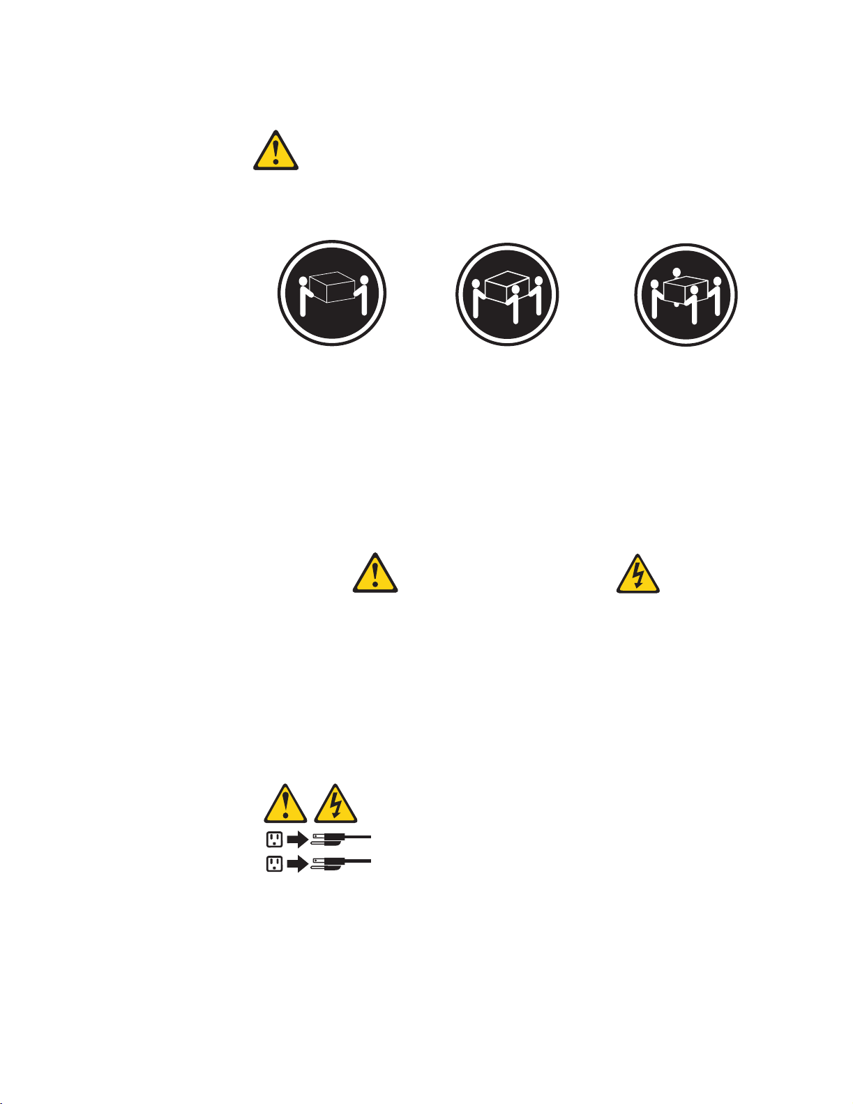
Statement 4
≥18 kg (39.7 lbs) ≥32 kg (70.5 lbs) ≥55 kg (121.2 lbs)
CAUTION:
Use safe practices when lifting.
Statement 5
CAUTION:
The power control button on the device and the power switch on the power
supply do not turn off the electrical current supplied to the device. The device
also might have more than one power cord. To remove all electrical current
from the device, ensure that all power cords are disconnected from the power
source.
2
1
x IBM® IntelliStation® E Pro: User’s Guide
Page 13
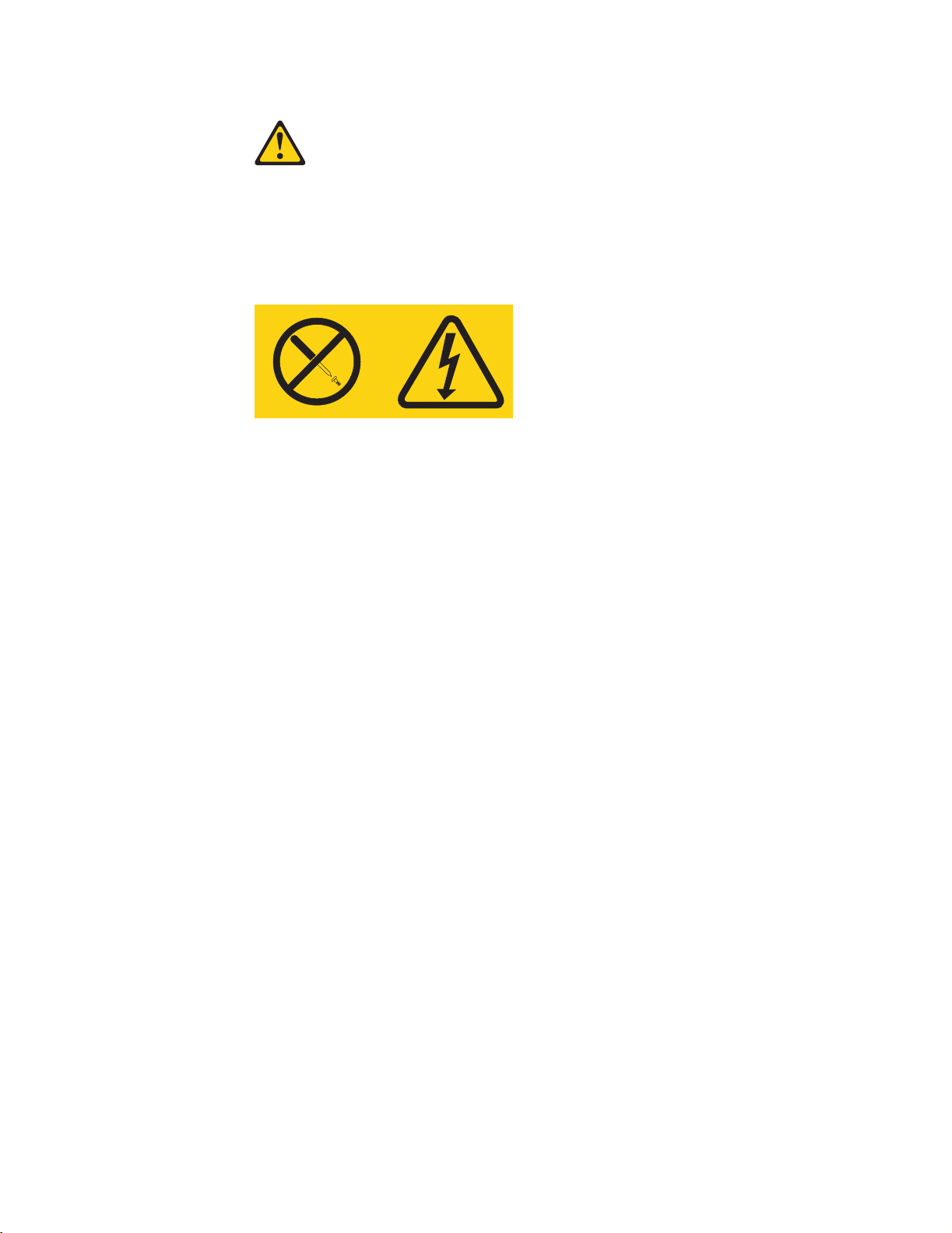
Statement 8
CAUTION:
Never remove the cover on a power supply or any part that has the following
label attached.
Hazardous voltage, current, and energy levels are present inside any
component that has this label attached. There are no serviceable parts inside
these components. If you suspect a problem with one of these parts, contact a
service technician.
Safety information xi
Page 14

xii IBM® IntelliStation® E Pro: User’s Guide
Page 15

Preface
This book will help you become familiar with your IBM® IntelliStation® E Pro computer
and its many features. This book describes how to set up, configure, operate,
maintain, and install options in your computer. Information about software, problem
solving, and getting help are also included.
Related Information
The following documentation contains additional information about your computer.
Because your computer comes with IBM-preinstalled software, you might be able to
view some of these documents in Access IBM. See “Using Access IBM” on page 16.
The IBM documents listed below can also be found at http://www.ibm.com on the
World Wide Web.
• Hardware Maintenance Manual
This publication contains information for trained service technicians. It can be
found at http://www.ibm.com/pc/support on the World Wide Web.
• README files on the Device Driver and IBM Enhanced Diagnostics CD
Several README files on this CD contain diagnostic tools and preinstalled device
drivers. Other README files on this CD contain information about the various
adapters and devices that might be attached to your computer.
• Adaptec SCSI documentation
This publication, accessible through Access IBM, contains information and
instructions for installing and configuring small computer systems interface
(SCSI) device drivers and devices.
• Safety Information
This publication, accessible through Access IBM, contains multilingual caution
and danger statements.
Notices and statements used in this book
The caution and danger statements used in this book also appear in the multilingual
safety information book that is accessible through Access IBM. Each statement is
numbered for easy reference corresponding to statements in the safety book.
The notices and statements are as follows:
• Notes: These notices provide important tips, guidance, or advice.
• Important: These notices provide information or advice that might help you avoid
inconvenient or problem situations.
• Attention: These notices indicate potential damage to programs, devices, or
data. An attention notice is placed just before the instruction or situation in which
damage could occur.
• Caution: These statements indicate situations that can be potentially hazardous
to you. A caution statement is placed just before the description of a potentially
hazardous procedure step or situation.
• Danger: These statements indicate situations that can be potentially lethal or
extremely hazardous to you. A danger statement is placed just before the
description of a potentially lethal or extremely hazardous procedure step or
situation.
© Copyright IBM Corp. 2000, 2001 xiii
Page 16

xiv IBM® IntelliStation® E Pro: User’s Guide
Page 17
Chapter 1. Introducing the IntelliStation E Pro
Thank you for selecting an IBM IntelliStation E Pro computer. Your computer
incorporates many of the latest advances in computing technology and can be
expanded and upgraded as your needs change.
If you have access to the Internet, you can obtain up-to-date information about your
computer and other IBM computer products at http://www.ibm.com/pc/intellistation on
the World Wide Web.
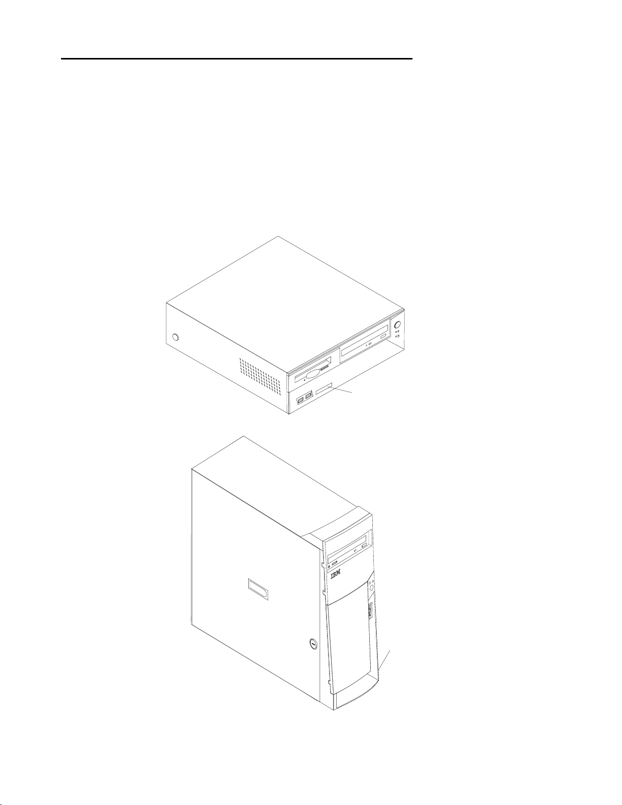
Refer to the following illustrations for the location of the computer model and serial
number labels. You will need these numbers to register your computer with IBM.
Note: The illustrations in this document might differ slightly from your hardware.
Desktop model:
Tower model:
Serial number
Serial number
© Copyright IBM Corp. 2000, 2001 1
Page 18

Features and specifications for the desktop model
The following table provides a summary of the features and specifications. Some
features and specifications are not available on all models.
Microprocessor:
®
Intel
Pentium® 4 with 256 KB
Level-2 cache
Memory:
• Minimum: 128 MB
• Maximum: 1.0 GB
• Type: PC133 DIMMs
• Slots: three dual inline
Internal drives:
• Hard disk drive: IDE
• One of the following:
— CD-ROM: IDE
— DVD-ROM: IDE
— CD-RW: IDE
Expansion bays:
• Two 5.25-in. bays (one CDROM drive installed, one hard
disk drive installed)
• One 3.5-in. bay (one diskette
drive installed)
PCI expansion slots:
Three 33 MHz/32-bit lowprofile slots on the system
board
Power supply:
160 watt (90-240 V ac)
Video adapter:
NVidia Quadro2 EX LP AGP
adapter with 32 MB video
memory
Size and weight:
• Height: 104 mm (4.1 in.)
• Depth: 412 mm (16.2 in.)
• Width: 360 mm (14.2 in.)
• Weight: approximately 9.1 kg (20
lb) when fully configured or 6.8 kg
(15.0 lb) minimum
Integrated functions:
• 10BASE-T/100BASE-TX Ethernet
controller on the system board with
RJ-45 Ethernet port
• Two serial ports
• One parallel port
• Two USB ports
• Keyboard port
• Mouse port
• Audio ports
— Line out
— Line in
— Mic
• Dual-channel bus mastering IDE
controller
Acoustical noise emissions:
• Sound power, idling: 5.1 bel
maximum
• Sound power, operating: 5.2 bel
maximum
Environment:
• Air temperature:
— Computer on: 10° to 35° C
(50.0° to 95.0° F). Altitude: 0
to 2133 m (6998.0 ft)
— Computer off: 10° to 43° C
(50.0° to 109.4° F). Maximum
altitude: 2133 m (6998.0 ft)
• Humidity:
— Computer on: 8% to 80%
— Computer off: 8% to 80%
Heat output:
Approximate heat output in British
thermal units (Btu) per hour
• Minimum configuration: 257 Btu
(75 watts)
• Maximum configuration: 686 Btu
(200 watts)
Electrical input:
• Sine-wave input (50-60 Hz)
required
• Input voltage low range:
— Minimum: 90 V ac
— Maximum: 137 V ac
• Input voltage high range:
— Minimum: 180 V ac
— Maximum: 265 V ac
• Input kilovolt-amperes (kVA)
approximately:
— Minimum: 0.08 kVA
— Maximum: 0.52 kVA
2 IBM® IntelliStation® E Pro: User’s Guide
Page 19

Features and specifications for the tower model
The following table provides a summary of the features and specifications. Some
features and specifications are not available on all models.
Microprocessor:
• Intel
Memory:
• Minimum: 128 MB
• Maximum: 1.5 GB
• Type: PC133 DIMMs
• Slots: three dual inline
Internal drives:
• Hard disk drive: IDE or SCSI
• One of the following:
Expansion bays:
• Two 5.25-in. bays (1 CD-ROM
• Five 3.5-in. bays (1 diskette
PCI expansion slots:
• Three 33 MHz/32-bit slots on
• Two 33 MHz/32-bit slots on the
Power supply:
Video adapter: (depending on
your model)
• Matrox G450 AGP adapter
• NVidia Quadro2 Pro AGP
®
Pentium® 4 with 256 KB
Level-2 cache
— CD-ROM: IDE
— DVD-ROM: IDE
— CD-RW: IDE
drive installed)
drive installed)
the system board
adapter extender card
340 watt (90-240 V ac)
with 16 MB SDRAM video
memory
adapter with 64 MB SDRAM
video memory
Size and weight:
• Height: 445 mm (17.5 in.)
• Depth: 498 mm (19.6 in.)
• Width: 165 mm (6.5 in.)
• Weight: approximately 19.5 kg (43
lb) when fully configured or 15.9 kg
(35 lb) minimum
Integrated functions:
• 10BASE-T/100BASE-TX Ethernet
controller on the system board with
RJ-45 Ethernet port
• Two serial ports
• One parallel port
• Two USB ports
• Keyboard port
• Mouse port
• Audio ports
— Line out
— Line in
— Mic
• Dual-channel bus mastering IDE
controller
Acoustical noise emissions:
• Sound power, idling: 5.1 bel
maximum
• Sound power, operating: 5.2 bel
maximum
Environment:
• Air temperature:
— Computer on: 10° to 35° C
(50.0° to 95.0° F). Altitude: 0
to 2133 m (6998.0.7 ft)
— Computer off: 10° to 43° C
(50.0° to 109.4° F). Maximum
altitude: 2133 m (6998.0 ft)
• Humidity:
— Computer on: 8% to 80%
— Computer off: 8% to 80%
Heat output:
Approximate heat output in British
thermal units (Btu) per hour
• Minimum configuration: 257 Btu
(75 watts)
• Maximum configuration: 1455 Btu
(425 watts)
Electrical input:
• Sine-wave input (50-60 Hz)
required
• Input voltage low range:
— Minimum: 90 V ac
— Maximum: 137 V ac
• Input voltage high range:
— Minimum: 180 V ac
— Maximum: 265 V ac
• Input kilovolt-amperes (kVA)
approximately:
— Minimum: 0.08 kVA
— Maximum: 0.52 kVA
Inventory checklist
Take an inventory of items as you unpack them to ensure that you have all of the
components. If any items are missing or damaged, contact your place of purchase.
The following is a list of items shipped with your IBM IntelliStation E Pro computer:
• One keyboard
• One mouse
Chapter 1. Introducing the IntelliStation E Pro 3
Page 20

Software
• One power cord (9-ft line cord)
• One compact disc with device drivers
• This User’s Guide
Your IBM IntelliStation E Pro computer comes with either Microsoft® Windows® 2000
1
Professional Workstation
software, including application programs, diagnostic tools, and device drivers. Some
software is preinstalled on your computer, and some software is on the Software
Selections CD and on the Device Drivers and IBM Enhanced Diagnostics CD that
come with your computer.
Important
The software, other than the Microsoft operating system, is licensed under the
terms of the IBM International License Agreement for Non-Warranted Pro-
grams. Use of your computer signifies acceptance of this license agreement.
For detailed instructions about viewing the license agreement, see Appendix D,
“Viewing the license agreement,” on page 121.
or Windows XP® Professional preinstalled and variety of
Preinstalled software
In addition to the Microsoft operating system, your preinstalled software includes the
following programs:
• Access IBM provides links to selected IBM Web sites and the IBM Assistant, a
help system for many tasks. Access IBM also provides shortcuts to help
accomplish many of these tasks. Double-click the Access IBM icon on the
desktop to display the Access IBM menu. If this icon is not on your desktop, find
Access IBM in the Start menu.
• Adobe Acrobat Reader is used to display portable document format (PDF) files.
You can download the most current versions of Adobe Acrobat Reader for other
languages and operating systems from the Adobe Web site at
http://www.adobe.com on the World Wide Web.
• ConfigSafe is a comprehensive configuration tracking and recovery tool. It
provides features that you can use to restore your system if your computer
becomes damaged, unusable, or unstartable.
• IBM Backup and Restore provides a link to the Web site from which you can
download the IBM Backup and Restore program. The program creates and
stores a backup image of the primary partition (drive C) of your hard disk drive.
You can recover this backup image in the event that drive C becomes damaged
or unusable.
• IBM Product Registration program can be used to register your computer with
IBM. When you register your computer with IBM, information is entered into an
IBM database, which enables IBM to contact you in case of a recall or other
severe problem. In addition, some locations offer extended privileges and
services to registered users.
• Online Books enables you to access documentation that contains detailed
information about your computer.
• PC-Doctor for Windows is a program to help you locate and resolve some
problems that might occur with your computer.
1.The Microsoft Certificate of Authenticity is your assurance that the Windows software in your computer is legally licensed from
Microsoft Corporation.
4 IBM® IntelliStation® E Pro: User’s Guide
Page 21

• Device drivers for factory-installed features are preinstalled on your computer.
The latest device drivers are also available at http://www.ibm.com/pc/support on
the World Wide Web.
• Product Recovery Program enables you to recover your operating system,
applications, and device drivers, if necessary.
Important
The Product Recovery Program is on a hidden, hard disk drive partition. Do not
delete or otherwise destroy this partition.
You must have Internet access to use some of these programs. For more information
about connecting to the Internet, refer to the operating system documentation that
comes with your computer.
See Chapter 3, “Operating your computer,” on page 19 for additional information
about your preinstalled software. For more information about using the recovery
programs and solving problems, see Chapter 6, “Solving problems,” on page 83.
Important:
1. You can reinstall the device drivers and applications that come with your
computer from the directories on your hard disk drive. For more information
about recovering your computer software, see “Recovering your operating system
and preinstalled software” on page 106.
2. The device drivers and some programs are also available at
http://www.ibm/com/pc/support on the World Wide Web and on the Device
Drivers and IBM Enhanced Diagnostics CD.
Software Selections CD
The Software Selections CD contains application programs and support software for
use with your computer, such as:
IBM Universal Manageability
(UM) Services
IBM Update Connector™ Use IBM Update Connector to download software
Norton AntiVirus for IBM Use Norton AntiVirus for IBM to detect and remove
®
Tivoli
Management Agent A network administrator can use this program to gather
IBM Backup and Restore You can use this program to create and store a backup
Provides a link to the Web site from which you can
download the IBM Universal Manageability Services
program. UM Services streamline and automate
personal computer (PC) systems management and
support tasks, such as asset deployment and tracking.
programs, software updates, data, and data updates
from the IBM Web site. Update Connector automatically
determines whether your computer needs available
updates, and, if so, it downloads and installs them at your
option.
viruses from your computer.
information about your computer and monitor its
operation.
image of the primary partition (drive C) of your hard disk
drive. You can recover this backup image in the event
that drive C becomes damaged or unusable. You can
download the latest version of this program by using the
IBM Backup and Restore link in the preinstalled software.
Chapter 1. Introducing the IntelliStation E Pro 5
Page 22

Other software CDs
Some IntelliStation models come with additional CDs. These CDs include software
that you can install and programs that you can run to test hardware components of
your computer.
Lotus® SmartSuite Lotus SmartSuite contains a package of powerful, award-
winning productivity applications and everything you need
to access the Internet. Your computer comes with either a
Lotus SmartSuite CD or a proof of entitlement to receive
one free CD-ROM version of Lotus SmartSuite. To install
your SmartSuite package, insert the Lotus SmartSuite CD
into your CD-ROM drive, or contact your network
administrator for assistance.
Device Drivers and IBM
Enhanced Diagnostics CD
The diagnostic test programs are stored on the Device
Drivers and IBM Enhanced Diagnostics CD that comes
with your computer. These programs provide the primary
methods of testing system components. Some of the
preinstalled device drivers are also stored on this CD.
What your IntelliStation E Pro computer offers
Your computer takes advantage of advancements in data storage, memory, systems
management, and network environments. Your computer includes:
• High performance accelerated graphics port (AGP) graphics
Your computer comes with an AGP graphics adapter installed. This high-
performance adapter supports high resolutions and includes many performanceenhancing features for your operating-system environment.
• Large system memory
The memory bus in your computer supports up to 1.5 GB of system memory. The
memory controller provides error code correction (ECC) support for up to three
industry-standard PC133, 3.3V, 168-pin, 133 Megahertz (MHz), unregistered,
synchronous dynamic random access memory (SDRAM) dual inline memory
modules (DIMMs).
• Systems-management capabilities
Your computer comes with features that a network administrator or file server can
can use to remotely manage and control your computer. Some of the features
®
include: Wake on LAN
Assistant. See “Managing your computer on a network” on page 21 for more
information.
• Integrated network environment support
Your computer comes with an Ethernet controller on the system board. This
Ethernet controller has an interface for connecting to 10-Mbps or 100-Mbps
networks. The computer automatically selects between 10BASE-T and
100BASE-TX environments. The controller provides full-duplex (FDX) capability,
which enables simultaneous transmission and reception of data on the Ethernet
local area network (LAN).
, Remote Administration, and System Migration
6 IBM® IntelliStation® E Pro: User’s Guide
Page 23

Reliability, availability, and serviceability features
Three important computer design features are reliability, availability, and serviceability
(RAS). The RAS features help to ensure the integrity of the data that is stored on your
computer, the availability of the computer when you need it, and the ease with which
you can diagnose and repair problems.
The following is an abbreviated list of the RAS features that your computer supports.
Many of these features are explained in later chapters of this publication.
• Reliability features
— Boot block recovery
— Cooling fans with speed-sensing capability
— Error code correction (ECC) front-side buses (FSBs)
— ECC L2 cache and system memory
— Parity checking on the small computer system interface (SCSI) and
peripheral component interconnect (PCI) buses
— Advanced configuration and power interface (ACPI)
— Power-on self-test (POST)
— Synchronous dynamic random access memory (SDRAM) with serial
presence detect (SPD)
• Availability features
— Advanced Desktop Management Interface (DMI) features
— Auto-restart initial program load (IPL) power supply
— Automatic error retry or recovery
— Automatic computer restart after power failure
— Built-in, menu-driven configuration and setup programs
— Built-in, menu-driven SCSI configuration programs (some models)
— Monitoring support for temperatures, voltages, and fan speed
— Upgradable basic input/output system (BIOS), diagnostics, and POST
— Wake on LAN (WOL) capability
• Serviceability features
— 24 hours a day, 7 days a week Customer support
— 3-year warranty
— Adaptec built-in self-test (BIST)
— Preinstalled Ethernet adapter
— CD-ROM-based diagnostics programs
— Diagnostic support of Ethernet adapters
— Error codes and messages
— Processor serial number access
— Read-only memory (ROM) checksums
— Vital product data (VPD); includes serial number information and
replacement part numbers, stored in nonvolatile memory, for easier remote
maintenance
Chapter 1. Introducing the IntelliStation E Pro 7
Page 24
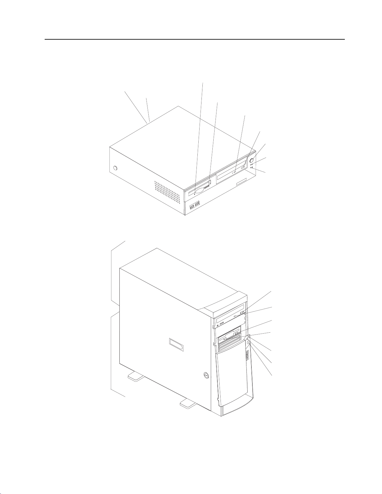
Computer controls and indicators
This section identifies the controls and indicators of the tower and desktop models.
Ethernet transmit/
receive activity
Ethernet speed
100 Mbs
Diskette drive
activity light
Diskette
eject button
CD-ROM drive
activity light
CD eject
button
Power-control
button
Power-on light
Hard disk drive
activity light
Note: The front bezel door is not shown here so that the drive bays are visible.
Ethernet speed 100 Mbps
CD eject
button
CD-ROM drive
activity light
Diskette eject
button
Diskette drive
activity light
Hard disk drive
activity light
Power-on
light
Power control
button
Ethernet transmit
receive activity
CD-ROM drive eject button: opens and closes the CD tray.
CD-ROM drive activity light: indicates when the CD-ROM drive is in use.
8 IBM® IntelliStation® E Pro: User’s Guide
Page 25

Diskette drive activity light: indicates when the diskette drive is in use.
Diskette drive eject button: releases a diskette from the drive.
Ethernet speed 100 Mbps: when this light is on, the Ethernet speed is 100 Mbps.
When this light is off, the Ethernet speed is 10 Mbps.
Ethernet transmit/receive activity: when this light is on, there is activity between
the computer and the network.
Power-control button: enables you to turn the computer on or off manually.
Power-on light: indicates when your computer is turned on.
Hard disk drive activity light: indicates when the hard disk drive is in use.
Chapter 1. Introducing the IntelliStation E Pro 9
Page 26

10 IBM® IntelliStation® E Pro: User’s Guide
Page 27

Chapter 2. Setting up your computer
This chapter provides information about setting up your computer and preparing it to
run your applications.
Read the “Safety information” on page vii before setting up your computer.
You will need the following items:
• Computer
• Computer power cord
• Keyboard
• Mouse
• Monitor (sold separately with signal cable and power cord)
If you are missing an item, contact your place of purchase.
Selecting a location for your computer
Make sure you have an adequate number of properly grounded electrical outlets for
the computer, monitor, and any other devices. Select a location for the computer
where it will remain dry. Leave about 50 mm (2 in.) of space around the computer for
proper air circulation. For information on arranging your computer and ease-of-use,
see the following sections.
Arranging your workspace
To get the most from your computer, arrange both the equipment you use and your
work area to suit your needs and the kind of work you do. Your comfort is of foremost
importance, but light sources, air circulation, and the location of electrical outlets can
also affect the way you arrange your workspace.
Comfort
The following guidelines will help you decide what working position suits you best.
Choose a chair to reduce fatigue from sitting in the same position for long periods.
The backrest and seat should adjust independently and provide good support. The
seat should have a curved front to relieve pressure on the thighs. Adjust the seat so
that your thighs are parallel to the floor and your feet are either flat on the floor, or on
a footrest.
When using the keyboard, keep your forearms parallel to the floor and your wrists in a
neutral, comfortable position. Try to keep a light touch on the keyboard, and your
hands and fingers relaxed. Change the angle of the keyboard for maximum comfort
by adjusting the position of the keyboard feet.
Adjust the monitor so that the top of the screen is at, or slightly below, eye level.
Place the monitor at a comfortable viewing distance, usually 51 to 61 cm (20 to 24
in.), and position it so that you can view it without having to twist your body.
Glare and lighting
Position the monitor to minimize glare and reflections from overhead lights, windows,
and other light sources. Place the monitor at right angles to light sources whenever
possible. Reduce overhead lighting, if necessary, by turning off lights or using lower
© Copyright IBM Corp. 2000, 2001 11
Page 28

wattage bulbs. If you install the monitor near a window, use curtains or blinds to block
the sunlight. You might have to adjust the Brightness and Contrast controls on the
monitor as the lighting changes throughout the day.
Where it is impossible to avoid reflections or to adjust the lighting, place an antiglare
filter over the screen. However, these filters might affect the clarity of the screen
image; try them only after you have exhausted other methods of reducing glare.
Dust compounds problems associated with glare. Clean your monitor screen
periodically using a soft cloth moistened with a nonabrasive, liquid glass cleaner.
Air circulation
Your computer and monitor produce heat. The computer fan pulls in fresh air and
forces out hot air. The monitor lets hot air escape through vents. Blocking the air
vents can cause overheating, possibly resulting in malfunction or damage. Place the
computer and monitor so that nothing blocks the air vents; usually 51 mm (2 in.) of air
space is sufficient. Also, make sure the vented air is not blowing on someone else.
Electrical outlets and cable lengths
The location of electrical outlets and the length of device power cords and cables
might determine the final placement of your computer.
When arranging your work space:
• Avoid the use of extension cords. Whenever possible, plug the computer power
cord directly into an electrical outlet.
• Keep power cords and cables neatly routed away from walkways and other areas
where they might be accidentally dislodged.
For more information about power cords, see “Power cords” on page 136.
Moving the stabilizing feet
The four feet attached to the bottom of the tower model computer provide additional
stability when the feet are placed in the stabilizing position.
Complete the following steps to place the feet in the stabilizing position.
1. Place the computer on its side.
2. Locate the release tab inside a foot; then, lift up on the tab.
3. Rotate the foot inward to the unlocked position; then, remove the foot from the
computer.
4. Align the post in the center of the foot with the hole on the bottom of the computer
and place the foot between the guides indicated on the computer.
12 IBM® IntelliStation® E Pro: User’s Guide
Page 29
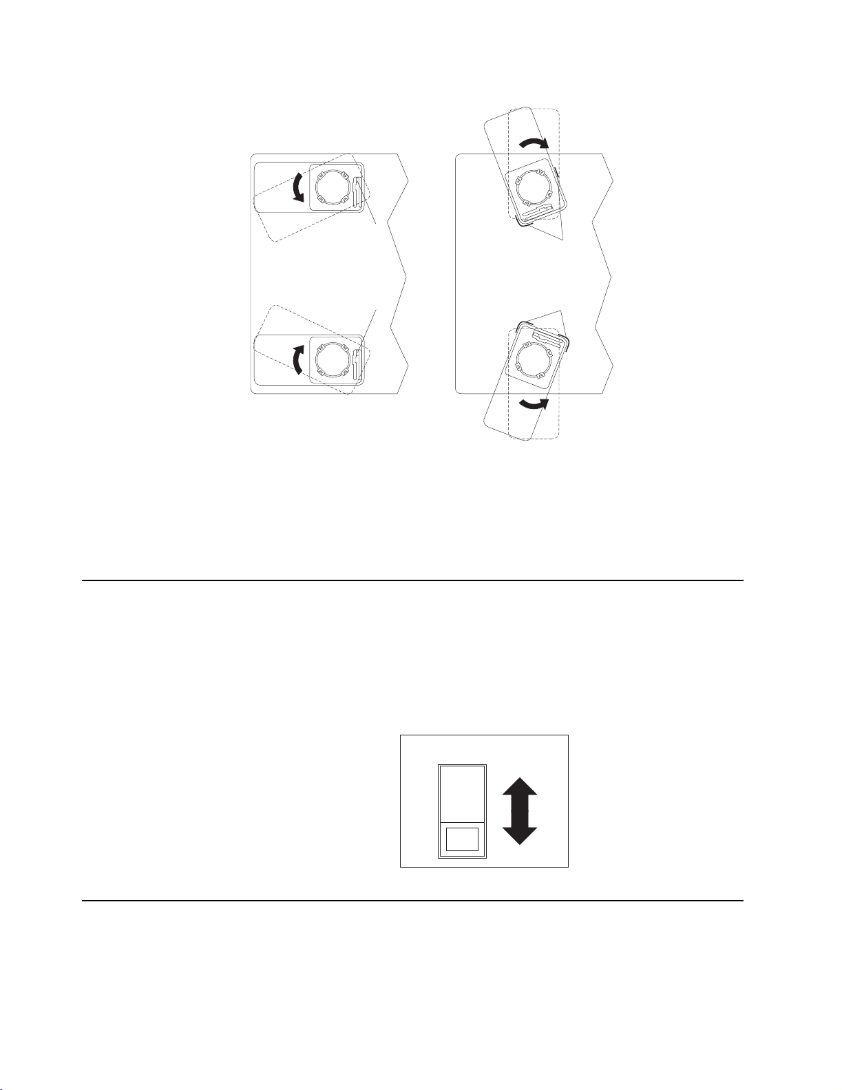
5. Rotate the foot outward until the foot locks into place.
Release tab
Feet (unlocked position) Feet (locked position)
Guides
Release tab
6. Complete steps 2 on page 12 through 5. for each foot.
Note: When you need to access the inside of the computer to install options, you
might find it easier to lay the computer on its side. If you do so, make sure that
the feet are in the non-stabilizing position. Otherwise, the feet might break off
the computer because of the weight of the computer.
Setting the voltage-selection switch
If you have a desktop model, check the position of the voltage-selection switch
located beside the power cord connector. Use a ballpoint pen to slide the switch, if
necessary.
• If the voltage supply range in your location is 90-137 V ac, set the switch to 115 V.
• If the voltage supply range in your location is 180-265 V ac, set the switch to 230
V.
Guides
Voltage switch
115
Connecting computer cables
Use the following steps to set up your computer. Look for the small icons on the
following pages, and on the back of your computer.
Chapter 2. Setting up your computer 13
Page 30
Your computer connector panel has color-coded connectors. If the cables use the
color-code conventions on your computer, match the color of the cable end with the
color of the connector. For example, match a blue cable end with a blue panel
connector, a red cable end with a red panel connector, and so on.
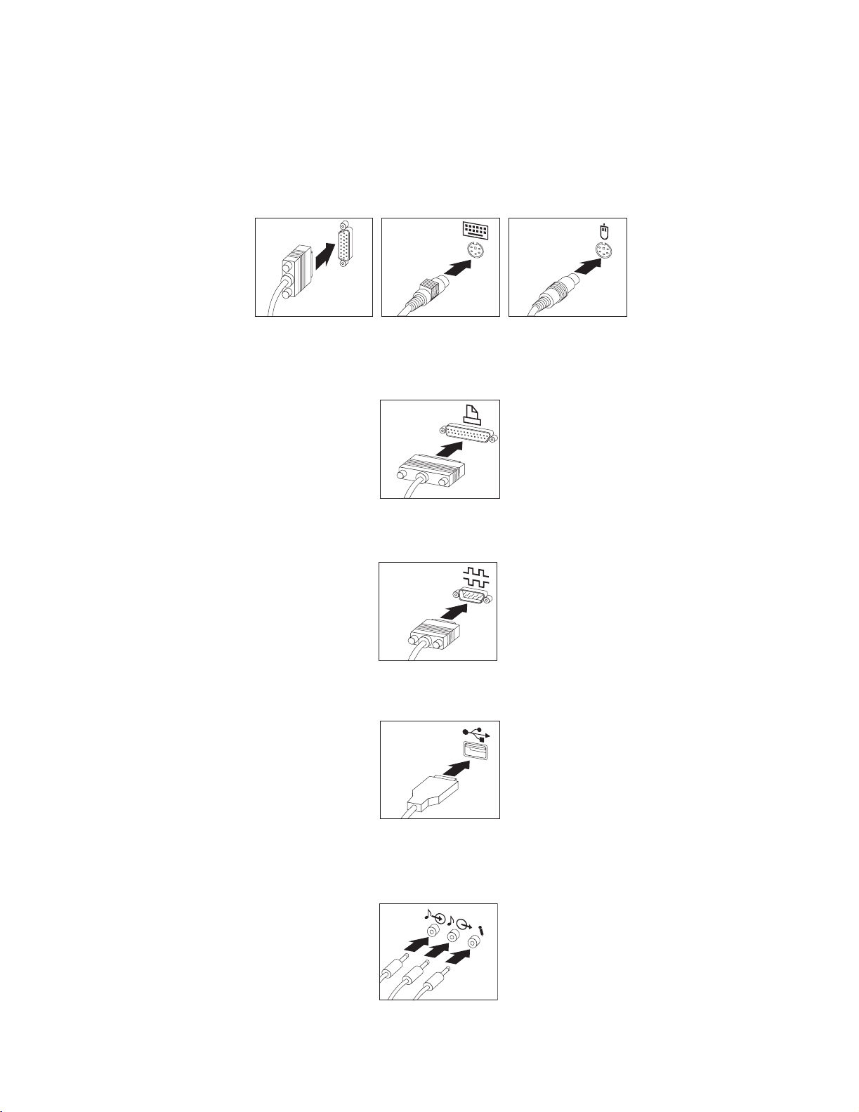
1. Connect the monitor cable to the monitor connector. Tighten the screws; then,
connect the keyboard cable to the keyboard connector, and connect the mouse
cable to the mouse connector.
Monitor
Keyboard Mouse
REQTEXT
2. Connect any additional devices you have.
• Connect a printer or parallel device to the parallel connector.
Parallel
REQTEXT
• Connect a serial device or external modem to the serial connector.
Serial
Device
REQTEXT
• Connect Universal Serial Bus (USB) devices to either of the USB connectors.
USB
Device
REQTEXT
• Connect optional devices, such as speakers, microphones, or headphones,
for models with an audio device. From left to right or top to bottom, depending
on your model, the audio connectors are Line in, Line out, and Mic.
Audio
14 IBM® IntelliStation® E Pro: User’s Guide
Page 31

• Connect the Ethernet cable to the RJ-45 Ethernet connector.
Important:
To operate the computer within FCC Class A limits, use a category 5 Ethernet
cable.
Ethernet
REQTEXT
3. Connect the power cord to the power connector located on the rear of the
computer. If there is a label covering the power connector, remove it.
Power
REQTEXT
4. Connect the power cords into properly grounded electrical outlets.
Note: When the power cord is first plugged in, the computer might turn on for a
few seconds, then turn off. This is normal.
Recording important numbers
Locate the serial, model, and type numbers. Record this information in Appendix C,
“Computer records,” on page 119. You will need these numbers when communicating
with IBM about your computer.
Running the operating system setup program
If you are starting your computer for the first time, the Microsoft Windows setup
program runs automatically when you start the computer. The program will prompt
you to make choices or type information. If you need more detailed information than
is provided in this User’s Guide, see your Microsoft operating-system manual.
Important information to know before you start:
• The setup program might be slightly different from the one described in your
operating-system manual. Some choices do not appear because they are preset.
• During the setup procedure, you must indicate that you accept the license
agreement.
• The Microsoft registration information will already be displayed in the registration
field. If the Product ID number is not already displayed, you must type it. The
Product ID is on a label attached to the computer.
To complete the setup program, you will need the following information.
• The Microsoft documentation that comes with your computer.
• Network information (if applicable) from your network administrator.
Chapter 2. Setting up your computer 15
Page 32

• The printer model and port, if a printer is attached directly to your computer.
Important
After turning on your computer for the first time, you must complete the operating system setup procedure before turning off your computer; otherwise, unexpected results might occur.
After the setup procedure finishes and the computer restarts, the Windows desktop
opens. Your computer is ready for use.
Registering your computer
Registering your computer helps IBM provide better service to you. When IBM
receives your registration information, it is placed into a central technical support
database. If you need technical assistance, the technical support representative will
have information about your computer. In addition, comments about your computer
are reviewed by a team dedicated to customer satisfaction and are taken into
consideration in making improvements to IBM computers. To register your computer,
use one of the following methods:
• Register through Access IBM. In Access IBM, click Get started. Click
Registering your IBM Computer, and then follow the instructions in the window.
(See “Using Access IBM” for further information.)
• If you have Windows 2000 Professional Workstation, click the IBM Register icon
on the desktop and follow the directions.
• Register your computer at http://www.ibm.com/pc/register on the World Wide
Web.
Note: The Register program that starts through Access IBM or the IBM
Registration icon will enable you to print the registration information and
provide a mailing address in the event no Internet access is available.
Using Access IBM
Access IBM is an interface through which you can quickly access information or
perform specific tasks.
The choices available from the Access IBM main menu are as follows:
• About your computer
Select this choice to display information about tasks that are typically performed
immediately after installing a new computer, personalizing your computer to fit
your needs, protecting your data, upgrading your computer hardware, purchasing
IBM services, purchasing IBM options, solving problems, and viewing the IBM
International License Agreement.
• Tools & Tips
Select this choice to display information about access support, diagnostic
programs, data backup and recovery tools, AntiVirus tools, data transfer tools,
configuration backup and restoration tools, and online books.
• On the Web
Select this choice to display information about obtaining additional information
and support on the World Wide Web.
16 IBM® IntelliStation® E Pro: User’s Guide
Page 33

Complete the following steps to use Access IBM.
1. Double-click the Access IBM icon on the Windows desktop. If the Access IBM
icon is not available on your desktop, click Start → Programs → Access IBM.
2. Click one of the categories listed on the menu (for example, Get Started).
3. Click a topic.
Installing other operating systems
Your computer comes with Microsoft Windows 2000 or Microsoft Windows XP
preinstalled.
To install another operating system, follow the instructions in the documentation
provided with the operating system and any updates. Then, follow the instructions in
the README file on the Device Driver and IBM Enhanced Diagnostics CD to install
the support software.
Note: If you install another operating system, you might need additional software or
device drivers. Hardware-specific support software is available on the Device
Driver and IBM Enhanced Diagnostics CD. If you experience problems with
the device drivers installed from this CD, you can obtain the latest device
drivers at http://www.ibm.com/pc/support on the World Wide Web.
Before installing any operating system, be sure you obtain the latest updates. Contact
the operating system manufacturer or, if applicable, check the manufacturer’s World
Wide Web site to obtain the updates.
Additional information about operating systems is posted periodically at
http://www.ibm.com/pc/support on the World Wide Web.
Product Recovery Program
The Product Recovery Program reinstalls your computer operating system and
preinstalled software. It is on the hidden partition on the hard disk. The Product
Recovery Program runs independently of the operating system.
If you are using FDISK, Disk Management, or another utility to reformat the hard disk
drive, you might see the partition where the Product Recovery Program is stored. Do
not delete this partition or the Product Recovery Program will be lost.
If your hard disk drive, including the partition where the Product Recovery Program
resides, becomes damaged or you replace the hard disk drive, contact IBM to order
the IBM Product Recovery CD to recover your preinstalled operating system,
application programs and device drivers. See “Getting information, help, and service”
on page 111 for details.
Creating emergency diskettes
At your earliest opportunity, create a Recovery Repair diskette, a Norton AntiVirus
Rescue diskette, and an IBM Enhanced Diagnostics diskette, and store them in a safe
place. Use the following sections to help you create a Recovery Repair diskette and a
Norton AntiVirus Rescue diskette. See “Creating an IBM Enhanced Diagnostics
diskette” on page 87 for information on how to create an IBM Enhanced Diagnostics
diskette.
Chapter 2. Setting up your computer 17
Page 34

Creating a Recovery Repair diskette
In the unlikely event that your desktop becomes unusable, the Recovery Repair
diskette will enable you to access the Product Recovery Program. Additional
information about the diskette is in Access IBM. For more information about using
this diskette, refer to “Using the Recovery Repair diskette” on page 107.
Do the following to create the Recovery Repair diskette:
1. From the Access IBM menu, click Protect data.
2. Click Creating emergency diskettes.
3. Click Recovery Repair diskette.
4. Follow the instructions on the screen.
Creating a Norton AntiVirus Rescue diskette
The Norton AntiVirus program periodically checks your drives for computer viruses.
Additional information about creating and using the diskette is in Access IBM.
Do the following to create the Norton AntiVirus Rescue diskettes:
1. From the Access IBM menu, click Protect data.
2. Click Creating emergency diskettes.
3. Click Norton AntiVirus Rescue Disks.
4. Follow the instructions on the screen.
18 IBM® IntelliStation® E Pro: User’s Guide
Page 35

Chapter 3. Operating your computer
This chapter provides information for the day-to-day use of your computer.
Turning on your computer
Do the following to start your computer:
1. Turn on all peripheral devices first.
2. Press the power-control button on your computer. For the location of the powercontrol button, see “Computer controls and indicators” on page 8.
What you see and hear when you start up your computer depends on the features
installed and the settings in the IBM Setup Utility program.
If power-on self-test (POST) detects a problem, there might be a series of beeps or no
beep, and a numeric error message might appear on the screen. Write down any
beep series and error code numbers with descriptions, then see “Troubleshooting
charts” on page 92 for the explanation of error codes.
During startup, the following messages might be displayed briefly:
• To start the Product Recovery Program, Press F11
• Hit <F2> if you want to run SETUP
• Press CTRL+A for SCSISelect Utility (some models only)
To use these features, press the appropriate function key or keys quickly. The
messages appear for only seconds. For more information about these messages,
see “Using the IBM Setup Utility program” on page 27 and “Using the SCSISelect
Utility program (some models)” on page 32.
During startup, you might not see Hit <F2> if you want to run SETUP. If you want
to see the prompt, see instructions for displaying the prompt in “Using the IBM Setup
Utility program” on page 27.
The IBM Setup Utility program will help you configure your computer with passwords,
PCI adapter configuration, and other options. The IBM Setup Utility menu is
displayed at the top of the screen. To navigate the menu and screen items, follow the
directions on the right of the screen.
The operating system and application programs initiate from the hard disk drive. If
your computer is attached to a network, the computer will begin attaching to any LANs
and remote applications to which you have access. A network administrator can also
"wake up" your computer (start it remotely) to download programs or gather
information about computer performance. For more information see, “Wake on LAN”
on page 21.
Using video features
Your computer has an accelerated graphics port (AGP) graphics adapter that renders
2D or 3D image quality and that uses a standard video protocol for displaying text and
graphic images on a monitor screen. The adapter supports a variety of video modes.
Video modes are different combinations of resolution, refresh rate, and color defined
by a video standard for displaying text or graphics.
© Copyright IBM Corp. 2000, 2001 19
Page 36

Video device drivers
To take full advantage of the graphics adapter in your computer, some operating
systems and application programs require custom software, called video device
drivers. These device drivers provide greater speed, higher resolution, more available
colors, and flicker-free images.
Device drivers for the graphics adapter and a README file with instructions for
installing the device drivers are provided on the Device Driver and IBM Enhanced
Diagnostics CD that comes with your computer and in the IBMTOOLS\DRIVERS
directory on the hard disk drive.
You can use the device driver installation instructions if you need to reinstall the
device drivers or if you need information on obtaining and installing updated device
drivers. For more information about installing device drivers, see “Recovering or
installing device drivers” on page 106.
Changing monitor settings
To get the best possible image on your screen and to reduce flicker, you might need to
reset the resolution and refresh rate of your monitor. You can view and change
monitor settings through your operating system using the instructions provided in the
README files on the Device Driver and IBM Enhanced Diagnostics CD or on the
hard disk drive in the drivers directory that comes with your computer. See your
operating system documentation for more information on monitor settings.
Attention: Before changing monitor settings, review the documentation that comes
with your monitor. Using a resolution or refresh rate that is not supported by your
monitor might cause the screen to become unreadable and could damage the
monitor. The information that comes with your monitor usually includes resolution
and screen refresh rates that your monitor supports. If you need additional
information, contact the manufacturer of the monitor.
If you are using a cathode ray tube (CRT) monitor, set your monitor for the highest
noninterlaced refresh rate that the monitor supports. If your monitor complies with the
VESA display data channel (DDC) standard, it is probably already set to the highest
refresh rate the monitor and video controller can support. If you are not sure if your
monitor is DDC-compliant, see the documentation provided with the monitor.
If you are using a flat-panel monitor, the refresh rate does not have to be set to the
highest noninterlaced refresh rate that the flat-panel monitor supports. Flat-panel
monitors produce flicker-free images even when they are operating at a minimum 60
Hz noninterlaced rate.
If you have a dual-monitor video adapter and you connect both monitors, you will be
prompted at the first startup afterwards to enable the Multi-head option, which
enables you to use both monitors. Click Yes to enable the option and use both
monitors.
Note: If you click No at the prompt, but want to use both monitors, you will need to
enable the multi-head option through the video adapter settings. For the
Matrox Millennium G450 video adapter, for example, you can enable the
option using the following procedure:
• If you have Windows 2000:
1. Right-click the Matrox PowerDesk icon on the right-hand portion of the
Windows 2000 task bar, and select Display properties.
2. Click Settings → Advanced → Dualhead → Enable dualhead → Apply.
3. If asked if you would like to keep this setting, click Yes.
20 IBM® IntelliStation® E Pro: User’s Guide
Page 37

• If you have Windows XP Professional:
1. Click Settings → Start → Control Panel → Appearance and Themes →
2. Click Advanced → Dualhead → Enable dualhead → Apply.
3. If asked if you would like to keep this setting, click Yes.
Using audio features
Your computer has an integrated audio controller that supports Sound Blaster
applications and is compatible with the Microsoft Windows Sound System. Your
computer also has a single internal speaker and three audio connectors. Using the
audio controller, you can record and play back sound and music to enhance
multimedia applications. Optionally, you can connect two stereo speakers to the Line
out connector to enjoy improved sound with multimedia applications.
The audio connectors in your computer are 3.5 mm (0.125-in.) mini-jacks. For the
location of the audio connectors, refer to “Input/output connectors” on page 75.
Line in
This connector accepts external devices, such as line output from a stereo, television,
or a musical instrument.
Display.
Line out
This connector is used to send audio signals from the computer to external devices,
such as speakers, headphones, or the audio line-in jack on a stereo system.
Note: The internal speaker on the computer is disabled when any devices are
attached to this connector.
Microphone
This connector accepts a microphone to record voice or other sounds on the hard
disk. With a microphone attached, you can also use speech recognition software.
Managing your computer on a network
Your computer comes with features that a network administrator or file server can use
to remotely manage and control your computer. The following sections describe some
of these network management tools.
IBM Universal Manageability Services (UM Services) streamline and automate
personal computer (PC) systems management and support tasks, such as asset
deployment and tracking. These utilities are available for IBM computers at no
additional charge, helping to reduce total cost of ownership of networked computers
so that you can focus vital company resources on essential business activities.
Go to http://www.ibm.com/pc/us/software/sysmgmt/ on the World Wide Web for more
information about available system management programs.
Wake on LAN
A network administrator can use the Wake on LAN™ feature to turn on your computer
from a remote location. When the Wake on LAN feature is used with network
Chapter 3. Operating your computer 21
Page 38

management software, many functions, such as data transfers, software updates, and
POST or BIOS updates can be performed on many computers simultaneously.
Intel Boot Agent
The Intel Boot Agent is a software program that enables your computer to startup
using a program code image supplied by a remote server. The features of Intel Boot
Agent are as follows:
• Compliant with the Wired for Management Baseline 2.0 (WfM 2.0)
• Incorporates the software defined in the PXE Boot Agent specification
• Includes support for Remote Program Load (RPL) runtime and loader software
(10/100 adapters only)
• Compatible with legacy boot agent environments that use BOOTP protocol
• Supported by remote installation programs such as LCCM and Microsoft RIS
For information about configuring the Intel Boot Agent, see “Using the Intel Boot
Agent Utility program” on page 33.
LANClient Control Manager (LCCM)
LANClient Control Manager (LCCM) is a graphical, server-based program that
performs mass unattended installations of operating systems, software, device
drivers, and BIOS code updates to remote systems. Used with the Wake on LAN
feature, LCCM can remotely turn on your computer, so that the installation can be
done while the computer is not being used.
For more information or to download this software go to
http://www.ibm.com/pc/us/desktop/lccm on the World Wide Web.
System Migration Assistant
System Migration Assistant (SMA) helps administrators remotely transfer
configurations, profile settings, printer device drivers, and files from an IBM or nonIBM PC to supported IBM systems.
For more information or to download this software go to
http://www.ibm.com/pc/us/software/sysmgmt/products/sma on the World Wide Web.
Desktop Management Interface
DMI is a method for gathering information about the hardware and software in your
computer. In a network environment, network administrators can use DMI to remotely
monitor and control your computer.
Using security features
To deter unauthorized use of your computer, you can use anti-intrusion features and
other security features that are provided with your computer.
Anti-intrusion features
IBM anti-intrusion features help protect against the theft of computer components,
such as the microprocessor, system memory modules, or disk drives.
A cover lock is built into your computer to prevent the cover from being removed. Two
identical keys for the cover lock are also supplied. A tag attached to the keys has the
key serial number and the address of the key manufacturer.
22 IBM® IntelliStation® E Pro: User’s Guide
Page 39

Important
Record the key-code number along with the manufacturer address and phone
number in the space provided in “Appendix C. Computer Records”. Because
locksmiths are not authorized to duplicate cover-lock keys, you must order
replacement keys from the key manufacturer. You will need the key code when
ordering replacement keys.
You can also set the chassis-intrusion detector switch inside the computer to alert the
network system administrator each time the computer cover is removed. For more
information about setting the chassis-intrusion alert, see Chapter 4, “Configuring your
computer,” on page 27.
Component protection
Your computer has individual component serial numbers that can be registered with a
third-party security company. You can also register the entire system. By registering
computer components, you can improve the chances of identifying the components if
they are ever stolen and recovered. For more information about component
registration, see the IBM support page at http://www.ibm.com/pc/us/desktop/assetid/
on the World Wide Web.
Data protection
You can lose data from the hard disk for a variety of reasons. Security violations,
viruses, or hard disk drive failures can all contribute to data loss. To help protect
against the loss of valuable information, IBM has incorporated the following datasaving features in your computer.
SMART hard disk drive
Your computer comes with a SMART hard disk drive that is enabled to report potential
hard disk failures. If an error is detected, a DMI-compliant warning message is sent to
the computer screen and, if the computer is part of a network, to an administrator
console. When an error is detected, the data on the hard disk can be backed up and
the drive replaced.
SMART Reaction
To help back up important data, IBM provides SMART Reaction™ software on the
computers with preinstalled software and also on the IBM Software Selections CD.
SMART Reaction is a client/server software application that helps users and
administrators respond effectively to a warning issued by the SMART hard disk drive.
Virus protection
Your computer has built-in virus protection that can be enabled through the IBM Setup
Utility program. This built-in protection checks for viruses in only the boot record.
Also, Norton AntiVirus for IBM is installed on the hard disk and on the IBM Software
Selections CD.
Locking the keyboard
You can lock the keyboard so that others are unable to use it. If a user password is set
using the IBM Setup Utility program, the keyboard is locked when you turn on the
computer. You must type the correct password before the keyboard will unlock. See
Setting Security Passwords in Access IBM or “Security” on page 29.
™
Some operating systems have a keyboard and mouse lock-up feature. See the
documentation that comes with your operating system for more information.
Chapter 3. Operating your computer 23
Page 40

Shutting down your operating system
When you are ready to turn off the computer, use the shutdown procedure for your
operating system to save data and prevent damage to your applications. See your
operating system manual for more information.
If you have Windows 2000, do the following to shut down your computer:
1. Save and close all files with which you are working.
2. Close all open applications.
3. Click the Windows Start button.
4. Click Shut Down; then click OK to confirm.
If you have Windows XP Professional, do the following to shut down your computer:
1. Save and close all files with which you are working.
2. Close all open applications.
3. Click the Windows Start button.
4. Click Turn Off Computer; then click Turn O ff to confirm.
Turning off your computer
You can turn off your computer as follows:
CAUTION:
The power control button on the device and the power switch on the power supply do
not turn off the electrical current supplied to the device. The device also might have
more than one power cord. To remove all electrical current from the device, ensure that
all power cords are disconnected from the power source.
2
1
• Press the power control button on the front of the computer. This starts orderly
shutdown of the operating system, if this feature is supported by your operating
system, and places the computer in standby mode.
Note: After turn off the computer, wait at least 5 seconds before you press the
power control button to turn on the computer again.
• Press and hold the power control button for more than 4 seconds to cause an
immediate shutdown of the computer and place the computer in standby mode.
You can use this feature if the operating system stops functioning.
24 IBM® IntelliStation® E Pro: User’s Guide
Page 41

• If you cannot use the power control button to turn off your computer, disconnect
the computer power cords from the electrical outlets.
Note: After disconnecting the power cords, wait approximately 15 seconds for
your computer to stop running.
Important
In some circumstances, your computer might not turn off immediately when you
press the power control button. If this happens, press and hold the power-control button until the computer turns off.
Chapter 3. Operating your computer 25
Page 42

26 IBM® IntelliStation® E Pro: User’s Guide
Page 43

Chapter 4. Configuring your computer
The following configuration programs are available to configure your computer:
• IBM Setup Utility program
The IBM Setup Utility program is part of the basic input/output system (BIOS)
code that comes with your computer. You can use this program to configure serial
port assignments, change interrupt request (IRQ) settings, change the device
startup sequence, set the date and time, and set passwords.
• SCSISelect Utility program (some models)
If your computer comes with a SCSI adapter, you can use the built-in SCSISelect
Utility program to configure devices that are attached to the SCSI adapter. Use
this program to change default values, resolve configuration conflicts, and
perform a low-level format on a SCSI hard disk drive.
• Intel Boot Agent Utility program
The Intel Boot Agent Utility program is part of the BIOS code that comes with your
computer. You can use this program to change network startup protocols and
startup order and to set menu wait times.
Using the IBM Setup Utility program
This section provides the instructions for starting the IBM Setup Utility program and
descriptions of the menu choices that are available.
Starting the IBM Setup Utility program
The IBM Setup Utility program starts automatically when POST detects that newly
installed or removed hardware is not reflected in your current configuration. A
diagnostic error message is displayed. See “Power-on self-test (POST)” on page 85
for details about POST and “Diagnostic error message tables” on page 89 for
information about the error messages.
To start the IBM Setup Utility program:
1. Turn on the computer and watch the monitor screen. If your computer is already
on when you start this procedure, you must shut down the operating system, turn
off the computer, wait a few seconds until all in-use lights go off, and restart the
computer. (Do not use Ctrl+Alt+Del to restart the computer.)
2. When the message Press F1 for Setup appears in the lower-left corner of the
screen during startup, press F1. (This prompt appears on the screen for only a
few seconds. You must press F1 quickly.)
Note: If you have set both user and administrator passwords, you must type the
administrator password to access the full IBM Setup Utility menu.
3. Follow the instructions that appear on the screen.
Use the left and right arrow keys to select menu choices on the menu bar at the top of
the screen. To change a setting on an item, select the item, and press Enter to
activate a setting selection dialogue box. Use the up and down arrow keys to select
the desired setting, and press Enter again.
© Copyright IBM Corp. 2000, 2001 27
Page 44

IBM Setup Utility main menu choices
The IBM Setup Utility main menu appears at the top of the IBM Setup Utility program
screen. Using the items of this menu, you can select settings that you want to
change. Item specific Help information for each menu item appears on the right hand
side of the IBM Setup Utility program screen. Select the item to view this information.
The choices on some menus might differ slightly, depending on the BIOS version on
your computer.
IBM Setup Utility
Main
Devices
System Summary
Product Data:
MachineType/Model
Flash EEPROM Revision Level
Boot Block Revision Level
System Board Identifier
System Serial Number
BIOS Date (MM/DD/YY)
System UUID
System Time (HH:MM:SS)
System Date (MM/DD/YY)
Language:
Startup
Advanced
ASOK999
20KT05AUS
2005A
SYSTEMBOARD
1234567
06/27/01
[09:44:40]
[07/02/2001]
[English (US)]
Security
Power Exit
Item Specific Help
Select this option to
view a summary of the
system hardware
configuration
F1 -/+ F9
Help Select Item Change Values Setup Defaults
Esc Enter F10
Exit Select Menu Select Sub-Menu Save and Exit
The following sections provide descriptions of the main menu choices.
Main
This choice is automatically selected when the IBM Setup Utility program starts.
Here, you can view general information about your computer, such as a summary of
components and computer configuration.
The type and speed of the microprocessor, the amount of memory that is installed, the
machine type and model number, the computer serial number, and the revision level
or issue date of the BIOS code that is stored in the flash electronically erasable
programmable ROM (EEPROM), appears under System Summary on this menu
choice. You can also view the language that your computer is set to display.
Changes that you make to configuration settings appear on this summary screen. You
cannot edit the fields of the configuration and system information, but you can set the
system date and time. The system time is in a 24-hour format: hour:minute:second.
Devices
Select this choice to view or change the assignments for devices and input/output
ports.
PS/2 Mouse: Select this choice to set whether a PS/2 pointing device is installed.
Diskette Drive A: Select this choice to set the type of diskette drive installed in your
computer. You can disable the diskette drive, or you can enable various types of
diskette drives.
Serial Port Setup: Select this choice to configure your computer serial ports. If the
port is set to Enabled, you can set the base input/output (I/O) address and the
interrupt. If the port is set to Automatic, the operating system automatically configures
these settings.
28 IBM® IntelliStation® E Pro: User’s Guide
Page 45

USB Setup: Select this choice to configure the USB ports in your computer. The
USB Support setting can be Enabled or Disabled. USB device support determines
whether BIOS support for USB devices will be enabled when you startup the
computer.
Parallel Port Setup: Select this choice to configure the parallel port of your
computer. If the port is set to Enabled, you can set the base input/output (I/O)
address, the interrupt, and the direct memory address (DMA). If the port is set to
Automatic, the operating system automatically configures these settings.
Video Setup: Select this choice to view the Video Setup menu. Select Active Video
determines which video mode will be active when you startup your computer. You can
select PCI, AGP, or Integrated in the menu. If the selected video is not available, the
computer will select a default video.
IDE Drives Setup: Select this choice to view or change the settings for IDE drives 0,
1, 2, or 3. You can set each drive for Compatible or High Performance. If an IDE
device attached to the system board IDE controller does not function properly or
causes other IDE devices attached to the same controller to function improperly, set
this field to the Compatible mode.
Audio Setup: Select this choice to enable or disable Audio Support.
Network Setup: Select this choice to set the system board Ethernet controller to
Enabled or Disabled. You can also enable Intel Boot Agent and PXE base code. The
menu also displays the MAC address for the computer.
Startup
Select this choice to view or change the start options. Start options take effect when
you start your computer.
You can select keyboard operating characteristics, such as the keyboard speed and
whether the computer starts with the keyboard number lock on or off. You also can
enable the computer to run without a diskette drive, monitor, or keyboard.
The computer uses a startup sequence to determine the device from which the
operating system starts. For example, you can define a startup sequence that checks
for a startable diskette in the diskette drive, then checks the hard disk drive in bay 1,
and then checks a network adapter.
You can enable a virus-detection test that checks for changes in the master boot
record at startup.
Advanced
Select this choice to change the values for advanced hardware features, such as PCI
configuration and Plug and Play operating system settings.
A message appears above the choices on this menu to alert you that the system
might malfunction if these options are configured incorrectly. Follow the instructions
on the screen carefully.
This choice identifies the microprocessor serial number in the microprocessor. The
setting cannot be changed.
Security
This choice appears at the top of the IBM Setup Utility screen. Select this choice to
set several security features, including adapter ROM security, security profile by
device, remote administration, and password protection. When you select Set
Chapter 4. Configuring your computer 29
Page 46

Passwords in the Security menu, you can implement either user password protection
or administrator password protection.
Adapter ROM Security: Set the field for this choice to Yes to lock the keyboard
during adapter ROM initialization. Use this setting with an administrator password to
prevent the use of adapter ROM based utilities.
Security Profile by Device: Select this menu choice to control the level of security
for bootable devices.
Remote Administration: Select this choice to enable Remote Administration and
Network Boot Integrity Services (BIS) protocol. Enable Remote Administration to run
utilities, such as the POST/BIOS Update Utility, without having to type an
administrator password.
Select whether to use the network Boot Integrity Services (BIS) protocol prior to
startup from the network. Before allowing a network startup, BIS ensures that the
startup image is valid and is authorized for your computer.
Set Passwords: Select this choice to set user and administrator passwords and to
set password protocols for updating the BIOS code and authorizing password
changes.
User password: After you set a user password, you can enable the unattended-start
mode. This locks the keyboard and mouse, but enables the computer to start the
operating system. The keyboard and mouse remain locked until you type the correct
password.
You can use any combination of up to seven characters (A–Z, a–z, 0–9, and blanks)
for your user password. Keep a record of your password in a secure place. If you
forget the user password, you can regain access to the computer through one of the
following methods:
• If an administrator password is set, type the administrator password at the poweron prompt. Start the IBM Setup Utility program and change the user password.
• Change the position of the CMOS recovery jumper. See “Erasing a lost or
forgotten password (clearing CMOS)” on page 108.
• Remove the battery and then install the battery.
Administrator password: Select this choice to set an administrator password. The
administrator password provides access to all choices on the IBM Setup Utility main
menu. You can set, change, or delete both the administrator and user passwords and
enable a user to change the user password.
Attention: If you set an administrator password and then forget it, you cannot
override or remove it. You must replace the system board.
30 IBM® IntelliStation® E Pro: User’s Guide
Page 47

The following table provides a summary of the password features.
Table 1. Power-on and administrator password features.
T y p e o f p a s s w o r d R e s u l t s
User password • Type the password to complete the system startup.
• A limited set of choices are available on the IBM Setup Utility
main menu.
Administrator password • No password is required to start the system.
• Type the password to access the IBM Setup Utility program.
• All choices are available on the IBM Setup Utility main menu.
Administrator and user
password
• You can type either password to complete the system startup.
• The administrator password provides access to all choices on
the IBM Setup Utility main menu. You can set, change, or
delete both the administrator and user passwords, and enable
you to change the user password.
• The user password provides access to a limited set of choices
on the IBM Setup Utility main menu. This limited access might
include changing or deleting the power-on password.
Power
Select this choice to enable or disable system power settings.
ACPI BIOS IRQ: This field controls what IRQ the Advanced Configuration and Power
Interface (ACPI) uses.
ACPI Standby Mode: Select which power level your computer uses in standby
mode. If S1 is selected, power is maintained to all devices, but all processor activity is
halted. If S3 is selected, power is maintained only for the main memory. Exit from the
S3 state might not be supported by all installed adapters.
APM BIOS Mode: This field controls the Advanced Power Management (APM)
support to your operating system. Enable this setting when your operating system
supports APM-enabled computers. When this option is set to disabled, all APM BIOS
support is disabled.
Power Savings: Maximum power savings conserves the greatest amount of system
power. Maximum performance conserves power but optimizes the performance of
the computer. To alter these settings, choose Customized. To turn off power
management, choose Disabled.
After Power Failure: This field controls whether the system will stay on after ac
power is removed and then restored. Select Power On if you use a power strip to turn
on the computer. Select Stay Off if you want the computer to remain off after power is
restored. Select Last State to have the computer return to its previous state.
Low Power Entry and Exit Activity Monitor: Select this choice to set up the
system activities that will be monitored for automatic power management.
Automatic Power On: Select this choice to control Automatic Power On when your
computer is unattended. You can set the Wake on LAN feature, Serial Port A Ring
Detect, PCI Modem Ring Detect, Wake Up on Alarm, and PCI Wakeup.
Exit
When you finish viewing or changing settings, select Exit from the menu bar at the top
of the IBM Setup Utility screen, then select Save and exit the Setup Utility and press
Chapter 4. Configuring your computer 31
Page 48

Enter. If you do not want to save your changes, select Exit the Setup Utility without
saving and press Enter.
If you want to save a change, but you do not want to leave the IBM Setup Utility
program, select Save Settings and press Enter.
You can select Restore Settings to load previous values for all Setup items, or your
can Load Default Settings for the computer.
Using the SCSISelect Utility program (some models)
SCSISelect is a built-in, menu-driven configuration utility program that you can use for
models that come with a SCSI adapter to:
• View the default SCSI IDs
• Locate and correct configuration conflicts
• Perform a low-level format on a SCSI hard disk
The following sections provide the instructions needed to start the SCSISelect Utility
program and descriptions of the menu choices available.
Starting the SCSISelect Utility program
To start the SCSISelect utility program:
1. Turn on the computer.
2. When the <<< Press <CTRL><A> for SCSISelect™ Utility! >>> prompt appears,
press Ctrl+A.
Note: If an administrator password has been set, a prompt appears asking you
to type the password to start the SCSISelect Utility program.
3. When the Would you like to configure the host adapter or run the SCSI
disk utility? question appears, make your selection and press Enter.
4. Use the arrow keys to select a choice from the menu.
• Press Esc to return to the previous menu.
• Press the F5 key to switch between color and monochrome modes (if your
monitor permits).
5. Follow the instructions on the screen to change the settings of the selected items,
and press Enter.
SCSISelect menu choices
The following choices appear on the SCSISelect Utility menu:
• Configure/View Host Adapter Settings
Select this choice to view or change the SCSI controller settings. To reset the
SCSI controller to its default values, press F6; then, follow the instructions that
appear on the screen.
32 IBM® IntelliStation® E Pro: User’s Guide
Page 49

You can view or change the following controller settings:
— Host Adapter SCSI ID
Select this choice to view the SCSI controller ID, normally 7.
— SCSI Parity Checking
Select this choice to view the assigned value of Enabled.
— Host Adapter SCSI Termination
Select this choice to view the assigned value of Enabled.
— Boot Device Options
Select this choice to configure startable device parameters. Before you can
make updates, you must know the ID of the device for which you want to
configure parameters.
— SCSI Device Configuration
Select this choice to configure SCSI device parameters. Before you can make
updates, you must know the ID of the device whose parameters you want to
configure.
Note: The Maximum Sync Transfer Rate represents the transfer rate for
Ultra SCSI devices.
– The transfer rate for Ultra3 SCSI LVD devices is 160 MBps
– The transfer rate for Ultra2 SCSI LVD devices is 80 MBps
– The transfer rate for Fast SCSI devices is 20 MBps
— Advanced Configuration Options
Select this choice to view or change the settings for advanced configuration
options.
• SCSI Disk Utilities
Select this choice to view the SCSI IDs that are assigned to each device or to
format a SCSI device.
To use the utility program, select a drive from the list. Read the screens carefully
before making a selection.
Note: If you press Ctrl+A before the selected drives are ready, an Unexpected
SCSI Command Failure screen might appear. Restart the computer and
watch the SCSISelect messages as each drive spins up. After the drive
that you want to view or format spins up, press Ctrl+A.
Using the Intel Boot Agent Utility program
The Intel Boot Agent Utility program is a built-in, menu-driven configuration utility
program that you can use to customize the network and startup protocols of your
computer through an operating system independent configuration program contained
within the adapter flash ROM.
Attention: If you change the startup order using the Intel Boot Agent Utility program,
startup sequence settings in the IBM Setup Utility program might not function properly.
Chapter 4. Configuring your computer 33
Page 50

Starting the Intel Boot Agent Utility program
To start the Intel Boot Agent Utility program:
1. Turn on the computer.
2. When the Initializing Intel (R) Boot Agent Version X.X.XX
PXE 2.0 Build XXX (WfM 2.0) prompt appears, press Ctrl+S.
Note: By default, you will have 2 seconds after the prompt appears on the
screen to press Ctrl+S.
3. Use the arrow keys or press Enter to select a choice from the menu.
• Press Esc to return to the previous menu.
• Press the F4 key to exit.
4. Follow the instructions on the screen to change the settings of the selected items,
and then press Enter.
Intel Boot Agent Utility menu choices
The following choices appear on the Intel Boot Agent Utility menu:
• Network Boot Protocol
PXE is the default value for this menu item. Use this setting for WfM-compatible
network management programs, such as Windows 2000 RIS, and Linux. Select
RPL for legacy-style remote startup.
• Boot Order
Attention: If you change the startup order using the PXE Boot Agent Utility
program, startup sequence settings in the IBM Setup Utility program might not
function properly.
Select this choice to change the order in which startup devices are queried.
— Try local drives first, and then network (default)
— Try network only
— Try local drives only
— Try network first, then local drives
Note: This option is not supported on this product. To change the startup order,
use the IBM Setup Utility program. See “Starting the IBM Setup Utility
program” on page 27 for more information.
• Show Setup Prompt
Select this choice to either display the PXE setup prompt or disable it. The
default setting is Disable.
When this choice is enabled, Press Ctrl+S to enter the setup menu appears on
the screen under the initializing prompt.
• Setup Menu Wait Time
Select this choice to set the amount of time (in seconds) that the system will
pause during initialization for a Ctrl+S input.
— 0 seconds
— 2 seconds (default)
— 3 seconds
— 5 seconds
— 8 seconds
34 IBM® IntelliStation® E Pro: User’s Guide
Page 51

• Legacy OS wake up support
Select this choice to enable or disable a non-Windows operating system to use
the adapter remote wake up capability. The default setting is Disabled.
Notes:
1. Use the default setting for Advanced Configuration and Power Interface
(ACPI) aware operating systems, such as Windows 2000 and Windows XP.
2. If your computer is running a non-ACPI operating system, you must set this
selection to enable it to use the Wake-on-LAN support.
3. When using a non-ACPI operating system, do not send a wake up packet to
the computer while it is turned on. If a wake up packet has been sent while
the computer is on, you might be unable to turn the computer off. See
“Troubleshooting charts” on page 92 for more information.
Chapter 4. Configuring your computer 35
Page 52

36 IBM® IntelliStation® E Pro: User’s Guide
Page 53

Chapter 5. Installing options
This chapter provides instructions to help you install or replace options on your
computer. For a list of supported options for your computer, go to
http://www.ibm.com/pc/support on the World Wide Web.
Before you begin
Before you begin to install options in your computer, read the following information:
• Read the handling guidelines in “Handling static-sensitive devices”, and read the
safety statements in “Safety information” on page vii. These guidelines will help
you work safely with your computer and options.
• Make sure that you have an adequate number of properly grounded electrical
outlets for your computer, monitor, and other options that you intend to install.
• Back up all important data before you make changes to disk drives.
• Have a small, flat-blade screwdriver available.
• Before accessing the inside of the tower model computer, rotate the two front
stabilizing feet a quarter turn in towards the computer, so they do not break.
Before placing the computer in an upright position, rotate the two front feet a
quarter turn outward from the computer. See “Moving the stabilizing feet” on
page 12.
• For a list of supported options for your computer, refer to
http://www.ibm.com/pc/support on the World Wide Web.
System reliability considerations
To help ensure proper system cooling and system reliability, make sure that:
• Each of the drive bays has a drive or a filler panel and electromagnetic
compatibility (EMC) shield installed.
• There is adequate space around the computer to allow the computer cooling
system to work properly. Leave approximately 51 mm (2 in.) of open space
around the front and rear of the computer. Do not place objects in front of the
fans.
• You have followed the instructions for cabling provided with optional adapters.
• You have replaced a failed fan as soon as possible.
Handling static-sensitive devices
Attention: Static electricity can damage electronic devices, including your computer.
To avoid damage, keep static-sensitive devices in their static protective bag until you
are ready to install them.
To reduce the possibility of damage from electrostatic discharge, observe the
following precautions.
• Limit your movement. Movement can cause static electricity to build up around
you.
• Handle the device carefully, holding it by its edges or its frame.
• Do not touch solder joints, pins, or exposed circuitry.
• Do not leave the device where others can handle and, possibly, damage the
device.
© Copyright IBM Corp. 2000, 2001 37
Page 54

t
M
• While the device is still in its static-protective package, touch it to an unpainted
metal part of the computer for at least two seconds. (This drains static electricity
from the package and from your body.)
• Remove the device from its package and install it directly into your computer
without setting the device down. If it is necessary to set the device down, place it
in its static-protective package. (If your device is an adapter, place it component
side up.) Do not place the device on your computer cover or on a metal table.
• Take additional care when handling devices during cold weather. Heating
reduces indoor humidity and increases static electricity.
Desktop model
Use the information in the following sections to install options in the desktop model
computer.
Major components of the desktop model
The following illustration shows the locations of major components in the desktop
model computer.
Adapter
retaining
bracket
Cover
Memory modules
Frame support bracke
Drive cages
CD-RO
drive
Diskette drive
38 IBM® IntelliStation® E Pro: User’s Guide
Page 55

System board
5
The illustrations in the following sections highlight various components on the system
board. Depending on installed options, your system board might look slightly
different.
Microprocessor
(J10TD2)
SCSI LED (J3
Chapter 5. Installing options 39
Page 56

System board internal cable connectors
The following illustration identifies system board connectors for internal cables.
Fan 3 support
bracket assembly
fan (J3)
Fan 2 microprocessor
fan sink (J19)
Main power
(J10K1)
Diskette drive
Primary IDE
(PRI IDE)
Secondary IDE
(SEC IDE)
Microprocessor
power (J3H1)
SCSI LED (J35)
System board external cable connectors
The following illustration identifies system board connectors for external devices.
Keyboard
Mouse
USB ports
Parallel
Serial ports
Ethernet
Audio
40 IBM® IntelliStation® E Pro: User’s Guide
Page 57

CMOS recovery jumper
The following illustration identifies the CMOS recovery jumper on the system board.
CMOS recovery
jumper (J33)
The CMOS recovery jumper can be used to clear CMOS memory in the event you
lose your user password. See “Erasing a lost or forgotten password (clearing
CMOS)” on page 108 for information on how to use the CMOS recovery jumper.
This jumper is also used to recover from a BIOS failure. See “Recovering from a
POST/BIOS update failure” on page 110.
Installing options in a desktop model
This section provides instructions for installing options in a desktop model.
Removing the cover
To remove the cover from the desktop model computer, do the following:
1. Review the information in “Before you begin” on page 37 and “Safety information”
on page vii.
2. Turn off the computer and all attached devices.
3. Disconnect all external cables and power cords.
Chapter 5. Installing options 41
Page 58

4. Press the buttons on either side of the computer cover and lift the cover from the
computer.
To replace the cover, see “Replacing the cover” on page 53.
Removing the frame support bracket
You must remove the frame support bracket to access many of the components of the
desktop model computer. To remove the frame support bracket, perform the following
steps:
1. Pivot the drive cages until the pivot locks catch the front of the desktop chassis,
holding the drive cages in place.
2. Lift the frame support bracket out of the computer.
To replace the frame support bracket, reverse the steps.
Working with adapters
Your computer comes with adapter connectors or slots. The AGP video adapter is
installed in the AGP slot. You can install up to three low-profile PCI adapters in PCI
slots 1 through 3. All PCI slots are 32-bit, 33 MHz slots.
42 IBM® IntelliStation® E Pro: User’s Guide
Page 59

The following illustration shows the location of expansion slots on the system board.
Microprocessor
(J10TD2)
SCSI LED (J35)
Adapter considerations: Before you install adapters, review the following:
• Locate the documentation that comes with the adapter and follow those
instructions in addition to the instructions provided in this chapter. If you need to
change the switch or jumper settings on your adapter, follow the instructions that
come with the adapter.
• You can install low-profile adapters in all three PCI slots.
• Your computer supports 5.0V and universal PCI adapters; it does not support
3.3V adapters.
• Your computer uses a rotational interrupt technique to configure PCI adapters.
Because of this technique, you can install a variety of PCI adapters that currently
do not support PCI interrupt sharing.
• PCI slots 1 through 3 are on PCI bus 0.
The system scans the AGP slot and PCI expansion slots 1 through 3 to assign
system resources; then the system starts the PCI devices in the following order:
PCI expansion slots 1 and 2, system board integrated drive electronics (IDE) or
SCSI devices, and then PCI expansion slot 3.
Note: To change the startup sequence for PCI devices, start the IBM Setup
Utility program, select Startup from the main menu, select Startup
Sequence, and select Second device (SCSI) to designate the adapter
startup sequence. See Chapter 4, “Configuring your computer,” on page
27 for details on using the IBM Setup Utility program.
Chapter 5. Installing options 43
Page 60

• For a list of supported options for your computer, refer to
http://www.ibm.com/pc/support on the World Wide Web.
Installing an adapter: Do the following to install an adapter in the desktop model:
Attention: When you handle static-sensitive devices, take precautions to avoid
damage from static electricity. For details on handling these devices, see “Handling
static-sensitive devices” on page 37.
1. Review the information in “Safety information” on page vii.
2. Turn off the computer and attached devices.
3. Disconnect all external cables and power cords; then remove the cover. See
“Removing the cover” on page 41.
4. Determine which PCI slot you will use for the adapter.
Note: Check the instructions that come with the adapter for any requirements,
restrictions, or cabling instructions. It might be easier to route any cables
before you install the adapter.
5. Rotate each drive bay cage until the drive cage latches catch the front of the
computer chassis.
6. Lift the frame support bracket. See “Removing the frame support bracket” on
page 42.
7. Rotate the rear adapter support bracket to the open (unlocked) position and
remove it from the computer.
8. Remove the expansion-slot cover. From the rear of the computer, press on the
slot cover. Grasp it and pull it out of the expansion slot. Store it in a safe place for
future use.
Attention: Expansion-slot covers must be installed on all vacant slots. This
maintains the electronic emissions standards of the computer and ensures proper
ventilation of computer components.
9. Set any jumpers or switches on the adapter or system board as described by the
adapter manufacturer.
10. When you are ready, remove the adapter from the static-protective package. It is
best to move the adapter directly from the static-protective package to the adapter
slot. If this is not possible, set the adapter down in its static-protective package
on a hard surface. Avoid touching the components and gold-edge connectors on
the adapter.
44 IBM® IntelliStation® E Pro: User’s Guide
Page 61

11. To install the adapter, carefully grasp the adapter by the top edge or upper
corners, and align it with the expansion slot guides; then press the adapter firmly
into the expansion slot.
Attention: Be certain that the adapter is correctly seated in the expansion slot
before you turn on the computer. Incomplete installation of an adapter might
damage the system board or the adapter.
12. Connect required cables to the adapter.
13. If you have another adapter, repeat steps 1 through 12. If you have another
option to install, do so now. Otherwise, complete the rest of the steps in this
section.
14. Reinstall the rear adapter support bracket; then rotate the bracket to the closed
(locked) position.
15. Replace the frame support bracket.
16. Return the drive bay cages to their original positions in the computer.
17. Replace the top cover, see “Replacing the cover” on page 53 for details.
18. Reconnect the external cables and power cords; then turn on the attached
devices and the computer.
Installing a SCSI adapter : Do the following to install an optional SCSI adapter:
1. If you do not have a preinstalled SCSI adapter, complete steps 1 through 12 of
“Installing an adapter” on page 44; then, continue with step 2.
2. Connect the SCSI signal cable to the adapter and one or more of the signal cable
connectors to the rear of the SCSI devices.
Chapter 5. Installing options 45
Page 62

3. Connect the SCSI activity indicator cable to the adapter and to the SCSI LED
connector (J35) on the system board. See “System board” on page 39 for the
location of the SCSI LED connector.
4. If you have other adapters or options to install or remove, do so now.
5. Reinstall the rear adapter support bracket; then rotate it to the closed (locked)
position.
6. Replace the frame support bracket.
7. Replace the cover. See “Replacing the cover” on page 53 for details.
8. Reconnect the external cables and power cords; then turn on the attached
devices and the computer.
Installing internal drives
Different types of drives enable your computer to read various types of media and
store data in different formats. Your computer comes with the following drives
preinstalled:
• Diskette
• Hard disk
• CD-ROM or DVD-ROM
Internal drive bays: The desktop model IntelliStation E Pro computer comes with an
IDE CD-ROM or DVD-ROM drive in bay 1, a 3.5-in., 1.44-MB diskette drive in bay 2,
and a hard disk drive installed in bay 3.
Bay 3
Bay 1 Bay 2
46 IBM® IntelliStation® E Pro: User’s Guide
Page 63

Notes:
1. The IntelliStation E Pro computer supports only one diskette drive.
2. The IntelliStation E Pro Type 6204 does not support the installation of additional
internal disk drives. However, you can replace failed internal drives.
3. For a complete list of supported options for your computer, refer to
http://www.ibm.com/pc/support/ on the World Wide Web.
Preinstallation steps : Before you replace drives in your computer, verify that you
have all the cables and other equipment specified in the documentation that comes
with the drive. You might also need to perform certain preinstallation activities. Some
steps are required only during the initial installation of an option.
1. Read “Safety information” on page vii, “Handling static-sensitive devices” on page
37, and the documentation that comes with your drive.
2. Choose the bay in which you want to install the drive.
3. Check the instructions that come with the drive to see if you need to set any
switches or jumpers on the drive. If you are installing a SCSI device, be sure to
set the SCSI ID for that device.
Installing a CD-ROM or diskette drive: To replace drives in the desktop model
computer, do the following:
1. Read the information in “Preinstallation steps”.
2. Turn off the computer and attached devices, and disconnect all external cables
and power cords.
3. Remove the cover. See “Removing the cover” on page 41 for details.
4. Disconnect power and signal cables to the drive.
5. Rotate the drive bay cage of the drive that you need to replace until the latch
catches the front of the computer chassis.
6. Remove the screws holding the drive in place.
7. Slide the drive out of the drive bay.
Note: If you are installing a drive that contains a laser, observe the following
safety precaution.
DANGER
Laser radiation when open. Do not stare into the beam, do not view directly with
optical instruments, and avoid direct exposure to the beam.
8. Touch the static-protective bag containing the drive to any unpainted metal
surface on the computer; then remove the drive from the bag and place it on a
static-protective surface.
9. Set any jumpers or switches on the drive according to the documentation that
comes with the drive.
Chapter 5. Installing options 47
Page 64

10. Slide the drive into the drive bay, and then attach the drive to the drive cage.
11. Connect one end of the diskette or IDE signal cable into the back of the drive and
the other end of the cable into the diskette or IDE connector on the system board.
For the location of the diskette or IDE connectors, see “System board internal
cable connectors” on page 40.
Note: Make sure to route the signal cable so that it does not block the air flow to
the rear of the drives or over the microprocessor.
12. Connect the power cable to the back of the drive. The connectors are keyed and
can be inserted only one way.
13. If you have other options to install or remove, do so now.
14. Replace the cover. See “Replacing the cover” on page 53 for details.
15. Reconnect the external cables and power cords; then turn on the attached
devices and the computer.
Installing a hard disk drive: To replace a hard disk drive in the desktop model
computer, do the following:
1. Read the information in “Preinstallation steps” on page 47.
2. Turn off the computer and attached devices and disconnect the external cables
and power cords.
3. Remove the cover and frame support bracket. See “Removing the cover” on
page 41 and “Removing the frame support bracket” on page 42 for details.
4. Disconnect the power and signal cables from both drives in the drive cage.
48 IBM® IntelliStation® E Pro: User’s Guide
Page 65

5. Remove the hard disk drive cage from the computer.
6. Slide the drive out of the drive bay.
7. Touch the static-protective bag containing the drive to any unpainted metal
surface on the computer; then remove the drive from the bag and place it on a
static-protective surface.
8. Set any jumpers or switches on the drive according to the documentation that
comes with the drive.
9. Attach the sliding rails to the sides of the hard disk drive using screws from the old
hard disk drive.
10. Slide the drive into the drive bay until the drive snaps into place, and replace the
drive cage.
11. Connect one end of the IDE signal cable into the back of the drive and the other
end of the cable into the IDE connector on the system board. For the location of
the IDE connectors, see “System board internal cable connectors” on page 40.
Note: Make sure to route the signal cable so that it does not block the air flow to
the rear of the drives or over the microprocessor.
12. Connect a power cable to the back of the drive. The connectors are keyed and
can be inserted only one way.
Chapter 5. Installing options 49
Page 66

13. If you have other options to install or remove, do so now.
14. Go to the appropriate section to work with another option, or replace the cover.
See “Replacing the cover” on page 53 for details.
15. Reconnect the external cables and power cords; then turn on the attached
devices and the computer.
Power and signal cables for internal drives: Your computer uses cables to
connect IDE devices to the power supply and to the system board. The following
cables are provided:
• Four-wire power cables connect the drives to the power supply. At the end of
these cables are plastic connectors that attach to different drives; these
connectors vary in size. Also, certain power cables attach to the system board.
• Flat signal cables, also called ribbon cables, connect IDE and diskette drives to
the system board. There are two sizes of ribbon cables that come with your
computer.
— The wider IDE signal cable has two or three connectors.
– If the cable has three connectors, one of these connectors is attached to
the drive, one is a spare, and the third attaches to the primary or
secondary IDE connector on the system board.
– If the cable has two connectors, one of these connectors is attached to
the hard disk drive, and the other attaches to the primary or secondary
IDE connector on the system board.
Note: The CD-ROM drive will have an ATA 66 signal cable. ATA 66 signal
cables are color-coded. The blue connector attaches to the system
board. The black connector attaches to the primary device. The gray
middle connector attaches to the secondary device. If you are
installing a hard disk drive, you must change the switch setting on the
CD-ROM drive to secondary and change the connector used for the
CD-ROM drive to the gray middle connector.
— The narrower signal cable has two connectors, one to attach to the diskette
drive, and the other to attach to the connector (FDD1) on the system board.
To locate connectors on the system board, see “System board internal cable
connectors” on page 40.
Review the following information before connecting power and signal cables to
internal drives:
• The drives that are preinstalled in your computer come with power and signal
cables attached. If you replace any drives, it is important to remember which
cable is attached to which drive.
• When you install a drive, ensure that the drive connector at the end of the signal
cable is always connected to a drive, and ensure that the drive connector at the
other end is connected to the system board. This reduces electronic noise from
the computer.
• If two IDE devices are used on a single cable, one must be designated as the
primary device and the other as the secondary device; otherwise, the computer
might not detect some of the IDE devices. The primary and secondary
designation is determined by switch or jumper settings on each IDE device.
• If two IDE devices are on a single cable, and only one is a hard disk drive, the
hard disk drive must be set as a primary device.
• If you have only one IDE device on a cable, it must be set as a primary device.
50 IBM® IntelliStation® E Pro: User’s Guide
Page 67

Installing memory modules
3
Adding memory to your computer is an easy way to make programs run faster. You
can increase the amount of memory in your computer by installing memory modules.
Your IntelliStation E Pro computer uses industry-standard, dual inline memory
modules (DIMMs).
Note: The desktop model does not support installing memory in DIMM connector 3.
Do the following to install a DIMM:
Attention: When handling static-sensitive devices, take precautions to avoid
damage from static electricity. For details on handling these devices, see “Handling
static-sensitive devices” on page 37.
1. Review the safety precautions listed in the “Safety information” on page vii.
2. Turn off the computer and all attached devices. Disconnect all external cables
and power cords; then remove the cover. See “Removing the cover” on page 41
or for details.
3. Lift the frame support bracket. See “Removing the frame support bracket” on
page 42.
4. Touch the static-protective package containing the DIMM to any unpainted metal
surface on the computer. Then remove the new DIMM from the package.
5. Gently open the retaining clip on each end of the DIMM slot. Turn the DIMM so
that the pins align correctly with the connector.
6. Insert the DIMM into the connector. Firmly press the DIMM straight down into the
connector by applying pressure on both ends of the DIMM simultaneously. The
retaining clips snap into the locked position when the DIMM is firmly seated in the
connector.
DIMM connector 1
DIMM connector 2
DIMM connector
7. If a gap exists between the DIMM and the retaining clips, the DIMM has not been
correctly installed. Open the retaining clips, remove the DIMM, then reinsert it.
8. If you have other options to install or remove, do so now.
9. Replace the frame support bracket.
10. Replace the cover. See “Replacing the cover” on page 53.
11. Reconnect the external cables and power cords. Turn on the attached devices,
and turn on the computer.
Chapter 5. Installing options 51
Page 68

Installing a security U-bolt
To help prevent theft, you can add a security U-bolt and cable to your computer.
Do the following to install the U-bolt:
1. Review the safety precautions listed in “Safety information” on page vii.
2. Turn off the computer and all attached devices. Disconnect all external cables
and power cords; then remove the cover. See “Removing the cover” on page 41
or “Removing the side cover” on page 58 for details.
3. Use a screwdriver to remove the two metal knockouts.
4. Insert the U-bolt through the rear panel; then attach and tighten the nuts.
5. Thread the cable through the U-bolt and around an object that is not part of or
permanently secured to the building structure or foundation, and from which the
cable cannot be removed. Fasten the cable ends together with a lock. After you
add the security cable, make sure that it does not interfere with other cables
connected to the computer.
6. Reconnect the external cables and power cords, and turn on the attached
devices, then the computer.
52 IBM® IntelliStation® E Pro: User’s Guide
Page 69

Replacing the cover
Do the following to replace the computer cover:
1. Clear any cables that might impede the replacement of the cover.
2. Install the side cover by placing it into position on the computer, with the notches
on the underside of the cover matching up to the holes along the sides of the
computer. Press down on the cover release latch button as you close the cover
release latch to lock the cover.
3. Reconnect the external cables and power cords to the computer; then connect
the power cords to electrical outlets.
4. Turn on the attached devices; then turn on the computer.
Chapter 5. Installing options 53
Page 70

Tower model
Use the information in the following sections to install options in the tower model
computer.
Major components of the tower model
The following illustration shows the locations of major components in the tower model
computer.
Rear adapter
retention bracket
Memory modules
Microprocessor
System board
Support bracket
Cover
Keylock button
Drive cage
Front adapter
retention bracket
EMC
shield
Filler
panel
Front door
54 IBM® IntelliStation® E Pro: User’s Guide
Page 71

System and PCI extender boards
The illustrations in the following sections highlight various components on the system
board.
This illustration identifies parts of the system board. Depending on installed options,
your system board might look slightly different.
SCSI LED (J35)
Chapter 5. Installing options 55
Page 72

)
System board internal cable connectors
The following illustration identifies system board connectors for internal cables.
Fan 3 support
bracket assembly
fan (J6L1)
Fan 2 microprocessor
fan sink (J7M2)
Main power
(J10K1)
Diskette drive
Primary IDE
(PRI IDE)
Secondary IDE
(SEC IDE)
Microprocessor
power (J3H1)
SCSI LED (J35
56 IBM® IntelliStation® E Pro: User’s Guide
Page 73

System board external connectors
The following illustration identifies system board connectors for external cables.
Keyboard
Mouse
USB ports
Parallel
Serial ports
Ethernet
Audio
Chapter 5. Installing options 57
Page 74

CMOS recovery jumper
The following illustration identifies the CMOS recovery jumper on the system board.
The CMOS recovery jumper can be used to clear CMOS memory in the event you
lose your user password. See “Erasing a lost or forgotten password (clearing
CMOS)” on page 108 for information on how to use the CMOS jumper.
This jumper is also used to recover from a BIOS failure. See “Recovering from a
POST/BIOS update failure” on page 110.
Installing options in a tower model
This section provides instructions for installing options in a tower model.
Removing the side cover
The following information describes how to remove the side cover.
Note: To remove the side cover, you might find it easier to lay the computer on its
side. If you do, move the stabilizing feet so that they do not break. See
“Moving the stabilizing feet” on page 12.
Do the following to remove the side cover of the computer:
1. Review the information in “Before you begin” on page 37 and “Safety information”
on page vii.
2. Turn off the computer and all attached devices.
3. Disconnect all external cables and power cords.
CMOS recovery
jumper (J33)
58 IBM® IntelliStation® E Pro: User’s Guide
Page 75

4. Pull the cover release latch away from the computer, and push the cover toward
the rear of the computer.
To replace the side cover, see “Replacing the cover” on page 73.
Attention: For proper cooling and airflow, replace the cover before turning on the
computer. Operating the computer with the cover removed might damage computer
components.
Removing the support bracket
When working with some options, such as hard disk drives, adapters, and memory
modules, you must first remove the support bracket to access the existing option.
Chapter 5. Installing options 59
Page 76

Do the following to remove the support bracket:
1. Pull out on the rear end of the support bracket approximately 150 mm (6 in.).
2. Pull the rear end of the support bracket away from the computer and place the
bracket aside.
To reinstall the support bracket, reverse the previous steps.
Working with adapters
Your computer comes with adapter connectors or slots. The AGP video adapter is
installed in the AGP slot. You can install up to five PCI adapters in PCI slots 1 through
5. All PCI slots are 32-bit, 33 MHz slots.
60 IBM® IntelliStation® E Pro: User’s Guide
Page 77

The following illustration shows the location of expansion slots on the system board.
Adapter considerations: Before you install adapters, review the following:
• Follow the instructions that come with the adapter in addition to the instructions in
this chapter. If you need to change the switch or jumper settings on your adapter,
follow the instructions that come with the adapter.
• You can install full-length adapters in all five PCI slots.
• Your computer supports 5.0V and universal PCI adapters; it does not support
3.3V adapters.
• Your computer uses a rotational interrupt technique to configure PCI adapters.
Because of this technique, you can install a variety of PCI adapters that currently
do not support sharing of PCI interrupts.
• PCI slots 1 through 5 are on PCI bus 0.
The system scans the AGP slot and PCI expansion slots 1 through 5 to assign
system resources. Then, the system starts the PCI devices in the following order,
if you have not changed the default startup sequence: PCI expansion slots 1 and
2, system board integrated drive electronics (IDE) or SCSI devices, and then PCI
expansion slots 3 through 5.
• For a list of supported options for your computer, refer to
http://www.ibm.com/pc/support/ on the World Wide Web.
Chapter 5. Installing options 61
Page 78

Installing an adapter: Do the following to install an adapter in the tower model:
Attention: When you handle static-sensitive devices, take precautions to avoid
damage from static electricity. For details on handling these devices, see “Handling
static-sensitive devices” on page 37.
1. Review the information in “Safety information” on page vii.
2. Turn off the computer and all attached devices.
3. Disconnect all external cables and power cords; then remove the side cover. See
“Removing the side cover” on page 58.
4. Determine which PCI slot you will use for the adapter.
Note: Check the instructions that come with the adapter for any requirements,
restrictions, or cabling instructions. It might be easier to route any cables
before you install the adapter.
5. For full-length adapters, rotate the rear adapter-retention bracket to the open
(unlocked) position and remove it from the computer. Rotate the front adapterretention bracket to the open position. If you are installing a smaller adapter,
remove only the rear adapter-retention bracket.
6. Remove the expansion-slot cover. From the rear of the computer, press on the
slot cover. Grasp it and pull it out of the expansion slot. Store it in a safe place for
future use.
Attention: Expansion-slot covers must be installed on all vacant slots. This
maintains the electronic emissions standards of the computer and ensures proper
ventilation of computer components.
7. Set any jumpers or switches on the adapter or system board as described by the
adapter manufacturer.
62 IBM® IntelliStation® E Pro: User’s Guide
Page 79

8. Remove the adapter from the static-protective package, and carefully grasp the
adapter by the top edge or upper corners, and align it with the expansion slot
guides; then press the adapter firmly into the expansion slot.
Note: It is best to move the adapter directly from the static-protective package to
the adapter slot. If this is not possible, set the adapter down on its staticprotective package on a hard surface. Avoid touching the components
and gold-edge connectors on the adapter.
Attention: Be certain that the adapter is correctly seated in the expansion slot
before you turn on the computer. Incomplete installation of an adapter might
damage the system board or the adapter.
Expansion
slot cover
Rear
adapter
retention
bracket
Adapter
Front
adapter
retention
bracket
9. Connect required cables to the adapter. Route cables so that they do not block
the flow of air from the fans.
10. If you have another adapter to install, repeat steps 1 through 10. If you have
another option to install, do so now.
11. If you have installed a full-length adapter, rotate the front adapter support bracket
to the closed (locked) position.
12. Reinstall the rear adapter support bracket; then rotate the bracket to the closed
(locked) position.
Note: The rear retaining bracket rests against the computer cover. You might
find it easier to lay the computer on its side to replace the cover.
13. Replace the support bracket.
14. Replace the side cover. See “Replacing the cover” on page 73 for details.
15. Reconnect the external cables and power cords; then turn on the attached
devices and the computer.
Chapter 5. Installing options 63
Page 80

Installing a SCSI adapter: Some models do not come with SCSI adapters. Do the
following to install an optional SCSI adapter:
1. If you do not have a preinstalled SCSI adapter, complete steps 1. through 9. of
“Installing an adapter” on page 62.
2. Connect the SCSI signal cable to the adapter and one or more of the signal cable
connectors to the rear of the SCSI devices.
3. Connect the SCSI activity indicator cable to the adapter and to the SCSI LED
connector (J35) on the system board. See “System board” on page 39 for the
location of the SCSI LED connector.
4. If you have other adapters or options to install or remove, do so now.
5. Rotate the front adapter-support bracket to the closed (locked) position.
6. Reinstall the rear adapter-support bracket; then rotate it to the closed (locked)
position.
7. Replace the support bracket.
8. Replace the cover, see “Replacing the cover” on page 73 for details.
9. Reconnect the external cables and power cords; then turn on the attached
devices and the computer.
64 IBM® IntelliStation® E Pro: User’s Guide
Page 81

Installing internal drives
Depending on your computer model, you might have one or more of the following
drives installed.
• Diskette
• Hard disk
• CD-ROM or DVD-ROM
Internal drive bays: The tower model IntelliStation E Pro tower model comes with
an IDE CD-ROM or DVD-ROM drive in bay 1, a 3.5-in., 1.44 MB diskette drive in bay
3, and a hard disk drive installed in bay 4.
Notes:
1. Diskette drives, tape drives, CD-ROM, and DVD-ROM drives are examples of
removable-media drives. You can install removable-media drives in bays 1, 2, 3,
and 4 only.
2. You can install a 3.5-in. slim-high, or a 5.25-in. half-high removable-media drive,
such as a tape backup drive, in bay 2.
3. You can only install a 3.5-in. slim-high removable-media drive in bay 4.
4. The IntelliStation E Pro computer supports only one diskette drive.
5. To install a 3.5-in. drive in a 5.25-in. bay, you must use a 5.25 in. conversion kit,
supplied with your option.
6. The electromagnetic interference (EMI) integrity and cooling of the computer are
protected by having all bays and PCI slots covered or occupied. When you install
a drive or PCI adapter, save the EMC shield and filler panel from the bay or the
PCI adapter slot cover in the event you later remove the option.
7. For a complete list of supported options for your computer, refer to
http://www.ibm.com/pc/support/ on the World Wide Web.
Chapter 5. Installing options 65
Page 82

Preinstallation steps : Before you install drives in your computer, verify that you
have all the cables and other equipment specified in the documentation that comes
with the drive. You might also need to perform certain preinstallation activities. Some
of the steps are required only during the initial installation of an option.
1. Read “Safety information” on page vii, “Handling static-sensitive devices” on page
37, and the documentation that comes with your drive.
2. Choose the bay in which you want to install the drive.
3. Check the instructions that come with the drive to see if you need to set any
switches or jumpers on the drive. If you are installing a SCSI device, be sure to
set the SCSI ID for that device.
Installing a drive in bay 2 or 4: Do the following to install a drive in bay 2 or 4:
Attention: When handling static-sensitive devices, take precautions to avoid
damage from static electricity. For details on handling these devices, see “Handling
static-sensitive devices” on page 37.
1. Read the information in “Preinstallation steps”.
2. Turn off the computer and attached devices and disconnect the external cables
and power cords.
3. Remove the side cover. See “Removing the side cover” on page 58 for details.
4. Remove the support bracket. See “Removing the support bracket” on page 59.
5. Use a screwdriver to pry the filler panel and EMC shield away from the computer.
Note: If you are installing a drive that contains a laser, observe the following
safety precaution.
DANGER
Laser radiation when open. Do not stare into the beam. Do not view directly with
optical instruments. Avoid direct exposure to the beam.
6. Touch the static-protective bag containing the drive to any unpainted metal
surface on the computer; then remove the drive from the bag and place it on a
static-protective surface.
7. Set any jumpers or switches on the drive according to the documentation that
comes with the drive.
8. You might find it easier to install the new drive into the appropriate opening on the
front, and then attach the cables.
9. If you are installing a 5.25-in. drive in bay 2, push the drive into the bay; then use
the two screws to attach the drive to the drive cage.
66 IBM® IntelliStation® E Pro: User’s Guide
Page 83

10. If you are installing a 3.5-in. drive in bay 2, you must attach the 5.25-in conversion
kit, supplied with your option, to the 3.5-in. drive.
Note: You can install only a 3.5-in. device in bay 4.
11. If the drive is an IDE device, connect one end of the IDE signal cable into the back
of the drive and the other end of the cable into the IDE connector on the system
board. For the location of the IDE connectors, see “System board internal cable
connectors” on page 40. If the drive is a SCSI device, connect one end of the
SCSI signal cable into the back of the drive and the other end of the cable into the
68-pin connector on the SCSI adapter.
Note: Route the signal cable so that it does not block the air flow to the rear of
the drives or over the microprocessor.
12. Connect the power cable to the back of the drive. The connectors are keyed and
can be inserted only one way.
13. If you have other options to install or remove, do so now.
14. Replace the support bracket.
15. Replace the side cover. See “Replacing the cover” on page 73 for details.
16. Reconnect the external cables and power cords; then turn on the attached
devices and the computer.
Installing a hard disk drive in bay 5, 6, or 7: Bays 5, 6, and 7 are in the drive cage.
The drive cage is located just above the front adapter-support bracket.
Note: You might find it useful to work with the computer laying on its side.
Chapter 5. Installing options 67
Page 84

To install a drive in bay 5, 6, or 7, do the following:
1. Read the information in “Preinstallation steps” on page 66.
2. Turn off the computer and all attached devices. Disconnect all external cables
and power cords; then remove the cover. See “Removing the side cover” on page
58 for details.
3. Remove the support bracket.
4. If your computer has hard disk drives preinstalled in the drive cage, disconnect
the power and signal cables from the rear of the drives.
5. Grasp the drive cage and rotate the cage out (middle view) of the computer until it
locks into place with the drive-cage retention tab. The open ends of the drive
slots and installed drives will face you.
Note: Ensure that the drive cage locks into place over the drive-cage retention
tab by pressing the drive cage all the way up.
6. Attach the guide rails to the side of the drive using the screws provided. If you
obtained your optional drive from IBM, the guide rails are blue plastic.
7. Slide the drive into the drive cage until the plastic tabs on the drive guide rails lock
into place in the drive cage. Clear any cables that might impede the replacement
of the drive cage.
8. Lift the drive cage up, and press in on the drive-cage release tab; then rotate the
cage back into the computer (right view).
9. Connect the power and signal cables to the rear of each drive.
Note: Route the signal cable so that it does not block the air flow to the rear of
the drives or over the microprocessor.
10. If you have other options to install or remove, do so now.
11. Replace the support bracket.
12. Replace the side cover. See “Replacing the cover” on page 73 for details.
13. Reconnect the external cables and power cords; then turn on the attached
devices and the computer.
68 IBM® IntelliStation® E Pro: User’s Guide
Page 85

Power and signal cables for internal drives: Your computer uses cables to
connect IDE and SCSI devices to the power supply and to the system board. The
following cables are provided:
• Four-wire power cables connect the drives to the power supply. At the end of
these cables are plastic connectors that attach to different drives; these
connectors vary in size. Also, certain power cables attach to the system board.
• Flat signal cables, also called ribbon cables, connect IDE, SCSI, and diskette
drives to the system board. Two or three sizes of ribbon cables come with your
computer.
— The wider IDE signal cable has two or three connectors.
– If the cable has three connectors, one of these connectors is attached to
the drive, one is a spare, and the third attaches to the primary or
secondary IDE connector on the system board.
– If the cable has two connectors, one of these connectors is attached to
the hard disk drive, and the other attaches to the primary or secondary
IDE connector on the system board.
Note: The CD-ROM drive is attached an ATA 66 signal cable. ATA 66 signal
cables are color-coded. The blue connector attaches to the system
board. The black connector attaches to the primary device. The gray
middle connector attaches to the secondary device. If you are
installing a hard disk drive, you must change the switch or jumper
setting on the CD-ROM drive to secondary and change the connector
used for the CD-ROM drive to the gray middle connector.
— The narrower signal cable has two connectors, one to attach to the diskette
drive, and the other to attach to the connector (FDD1) on the system board.
— If your computer comes with a SCSI adapter and SCSI hard disk drive, the
following cables can be used to attach SCSI devices to the SCSI host
adapter:
– An Ultra160 twisted ribbon cable connects the internal Ultra160 SCSI
hard disk drive to the SCSI connector on the SCSI adapter. This cable
has five additional connectors for attaching more internal SCSI devices.
– A round SCSI cable connects external SCSI devices to the SCSI adapter
so that you can add external SCSI devices. For more information about
connecting SCSI devices, see the SCSI documentation on the Software
Selections CD that comes with your computer.
To locate connectors on the system board, see “System board internal cable
connectors” on page 40.
Review the following information before connecting power and signal cables to
internal drives:
• The drives that are preinstalled in your computer come with power and signal
cables attached. If you replace any drives, remember which cable is attached to
which drive.
• When you install a drive, ensure that the drive connector at the end of the signal
cable is connected to the drive and that the drive connector at the other end is
connected to the system board. This reduces electronic noise from the computer.
• If two IDE devices are used on a single cable, one must be designated as the
primary device and the other as the secondary device; otherwise, the computer
might not recognize some of the IDE devices. The primary and secondary
designation is determined by switch or jumper settings on each IDE device.
• If two IDE devices are on a single cable, and only one is a hard disk drive, the
hard disk drive must be set as a primary device.
Chapter 5. Installing options 69
Page 86

• If you have only one IDE device on a cable, it must be set as a primary device.
Installing memory modules
Adding memory to your computer is an easy way to make programs run faster. You
can increase the amount of memory in your computer by installing memory modules.
Your IntelliStation E Pro computer uses industry-standard dual inline memory
modules (DIMMs).
Do the following to install a DIMM:
Attention: When handling static-sensitive devices, take precautions to avoid
damage from static electricity. For details on handling these devices, see “Handling
static-sensitive devices” on page 37.
1. Review the safety precautions listed in the “Safety information” on page vii.
2. Turn off the computer and all attached devices. Disconnect all external cables
and power cords; then remove the cover. See “Removing the side cover” on page
58 for details.
3. Remove the support bracket. See “Removing the support bracket” on page 59.
4. Touch the static-protective package containing the DIMM to any unpainted metal
surface on the computer. Then remove the new DIMM from the package.
5. Open the retaining clips and, if necessary, remove any existing DIMM.
6. Gently open the retaining clip on each end of the DIMM slot. Turn the DIMM so
that the pins align correctly with the connector.
70 IBM® IntelliStation® E Pro: User’s Guide
Page 87

7. Insert the DIMM into the connector. Firmly press the DIMM straight down into the
connector by applying pressure on both ends of the DIMM simultaneously. The
retaining clips snap into the locked position when the DIMM is firmly seated in the
connector.
DIMM connector 1
DIMM connector 2
DIMM connector 3
8. If a gap exists between the DIMM and the retaining clips, the DIMM has not been
correctly installed. Open the retaining clips, remove the DIMM, then reinsert it.
9. If you have other options to install or remove, do so now.
10. Replace the support bracket.
11. Replace the side cover. See “Replacing the cover” on page 73.
12. Reconnect the external cables and power cords. Turn on the attached devices,
and turn on the computer.
Installing a security U-bolt
To help prevent theft, you can add a security U-bolt and cable to your computer. This
section discusses how to install a security U-bolt.
Do the following to install the U-bolt:
1. Review the safety precautions listed in “Safety information” on page vii.
2. Turn off the computer and all attached devices. Disconnect all external cables
and power cords; then remove the cover. See “Removing the side cover” on page
58 for details.
3. Use a screwdriver to remove the two metal knockouts.
4. Insert the U-bolt through the rear panel; then attach and tighten the nuts.
Chapter 5. Installing options 71
Page 88

5. Thread the cable through the U-bolt and around an object that is not part of or
permanently secured to the building structure or foundation, and from which the
cable cannot be removed. Fasten the cable ends together with a lock. After you
add the security cable, be certain it does not interfere with other cables connected
to the computer.
6. Reconnect the external cables and power cords, and turn on the attached
devices, and then the computer.
72 IBM® IntelliStation® E Pro: User’s Guide
Page 89

Replacing the cover
Do the following to replace the cover of the tower model:
Note: If you removed the support bracket, reinstall it before you replace the cover.
See “Removing the support bracket” on page 59 for details.
1. Clear any cables that might impede the replacement of the cover.
2. Install the side cover by placing it into position on the computer. Be certain the
notches on the underside of the cover match up to the holes along the sides of the
computer. Press down on the cover release latch button as you close the cover
release latch to lock the cover.
3. If you have not done so already, make sure that the two front stabilizing feet are
rotated outward so that they properly support the computer. Rotate each
individual foot outward 90 degrees.
4. Reconnect the external cables and power cords to the computer; then connect
the power cords to electrical outlets.
5. Turn on the attached devices; then turn on the computer.
Connecting external options
You can connect a number of optional external devices to the connectors on the rear
and front of the computer. If your computer comes with a SCSI adapter installed, you
can attach a SCSI storage expansion enclosure to your computer.
Chapter 5. Installing options 73
Page 90

To attach an external device:
1. Read “Before you begin” on page 37, review the safety precautions listed in
Statement 1 and Statement 5 in “Safety information” on page vii, and read the
documentation that comes with your options.
2. Be sure that your computer and all attached devices are turned off.
3. Follow the instructions that come with the option to prepare it for installation and
to connect it to the computer.
Note: If you are attaching a SCSI device, see “Ultra160 SCSI connector” on
page 80 for SCSI ID and cabling information.
Input/output connector locations
Desktop model:
Mouse
USB 1
Parallel
Line inLine out
Keyboard
USB 2
Tower model:
Power cord
connector
Mouse
Keyboard
USB 1
USB 2
Parallel
Serial 1
Serial 2
Ethernet
Mic (pink)
Line out (green)
Line in (blue)
Video
SCSI (optional)
Serial 1
1
2
2
1
Serial 2
Ethernet
Microphone
Video
Power cord connector
74 IBM® IntelliStation® E Pro: User’s Guide
Page 91

Input/output connectors
This section provides pin and other information about the input/output connectors on
the rear of your computer. Refer to “Computer controls and indicators” on page 8.
These connectors are:
• One mouse
• One keyboard
• One parallel
• Two serial
• One Ethernet
• Two USB
• Line in
• Line out
• Microphone
• One video (Optional multiple connectors on some models)
• One Ultra160 SCSI (some models)
Video connector
Your computer uses an AGP adapter located in the AGP slot on the system board.
The video connector is on the adapter and is located on the rear of your computer.
See “Input/output connectors” for the location of this connector.
5
Table 2. Monitor connector-pin assignments.
Pin Signal I/O Pin Signal I/O
1 Red O 9 +5 V dc, used by DDC2B
2 Green I 10 Ground
3 Blue O 11 Monitor ID 0 – not used
4 Monitor ID 2 – not used I 12 DDC2B data I/O
5 Ground 13 Horizontal sync O
6 Red ground 14 Vertical sync O
7 Green ground 15 DDC2B clock I/O
8 Blue ground
1
1115
Some models come with a digital video interface (DVI) connector for connecting a
digital monitor.
1
C1 C2
C3C5C4
Chapter 5. Installing options 75
Page 92

Table 3. DVI monitor connector-pin assignments.
Pin Signal description Pin Signal description
1 TMDS Data2- 16 Hot plug detect
2 TMDS Data2+ 17 TMDS Data0-
3 Data2/4 shield 18 TMDS Data0+
4 TMDS Data4- 19 Data0/5 shield
5 TMDS Data4+ 20 TMDS Data5-
6 DDC clock 21 TMDS Data5+
7 DDC Data 22 Clock shield
8 Analog VSync 23 TMDS clock+
9 PMDS Data1- 24 TMDS Clock-
10 TMDS Data1+ C1 Analog red
11 Data1/3 shield C2 Analog green
12 TMDS Data3- C3 Analog blue
13 TMDS Data3+ C4 Analog HSync
14 +5 V power C5 Analog ground
15 Ground (for +5 V)
Keyboard connector
Your computer has one keyboard connector. See “Input/output connectors” on page
75 for its location.
Note: If you attach a standard (non-USB) keyboard to the keyboard connector, the
USB ports and devices are disabled during the power-on self-test (POST).
6
4
2
Table 4. Keyboard-connector (6-pin female) pin-number assignments.
Pin I/O Signal
1I/OData
2N/AReserved
3 N/A Ground
4 N/A +5 V dc
5
3
1
5 I/O Keyboard clock
6N/AReserved
Mouse connector
Your computer has one mouse connector that supports a mouse or other pointing
device. The mouse connector is located on the rear of your computer. For the
location, see “Input/output connectors” on page 75.
76 IBM® IntelliStation® E Pro: User’s Guide
Page 93

6
4
2
Table 5. Auxiliary or pointing-device connector (6-pin female) pin-number assignments.
Pin Signal
1Data
2 Not connected
3 Ground
4 +5 V dc
5Clock
6 Not connected
5
3
1
Parallel connector
Your computer has one parallel connector. This connector supports three standard
Institute of Electrical and Electronics Engineers (IEEE) 1284 modes of operation:
standard parallel port (SPP), enhanced parallel port (EPP), and extended capability
port (ECP).
Viewing or changing the connector assignments: Use the IBM Setup Utility
program to configure the parallel connector as bidirectional. With this configuration,
data can be read from and written to a device. In bidirectional mode, the computer
supports the ECP and EPP modes.
Do the following to view or change the parallel-connector assignment:
1. Restart the computer.
2. Press and hold the F1 key to launch the IBM Setup Utility program.
3. On the IBM Setup Utility menu, use the cursor keys on the keyboard to select
Devices→Parallel Port.
Note: When you configure the parallel connector as bidirectional, use an IEEE
1284-compliant cable. The cable must not exceed 3 meters (9.8 ft).
4. Follow the instructions on the screen to save your changes and exit from the IBM
Setup Utility menu.
Parallel connector pin-assignments: There is a 25-pin, female D-shell parallel
connector on the rear of your computer, see “Input/output connectors” on page 75 for
the location of this connector.
13
25
1
14
Chapter 5. Installing options 77
Page 94

Table 6. Parallel connector-pin assignments.
Pin Signal I/O Pin Signal I/O
1 STROBE# I/O 14 AUTO FD XT# O
2 Data bit 0 I/O 15 ERROR# I
3 Data bit 1 I/O 16 INIT# O
4 Data bit 2 I/O 17 SLCT IN# O
5 Data bit 3 I/O 18 Ground
6 Data bit 4 I/O 19 Ground
7 Data bit 5 I/O 20 Ground
8 Data bit 6 I/O 21 Ground
9 Data bit 7 I/O 22 Ground
10 ACK# I 23 Ground
11 BUSY I 24 Ground
12 PE I 25 Ground
13 SLCT I
Serial connectors
Your computer has two standard 9-pin D-shell serial connectors: Serial connector 1
and Serial connector 2. See “Input/output connectors” on page 75 for their location.
1
69
Table 7. Serial-port connectors pin-number assignments.
Pin Signal Pin Signal
1 Data carrier detect 6 Data set ready
2 Receive data 7 Request to send
3 Transmit data 8 Clear to send
4 Data terminal ready 9 Ring indicator
5 Signal ground
5
Ethernet connector
Your computer comes with an integrated Ethernet controller. This controller provides
an interface for connecting to 10-Mbps or 100-Mbps networks and provides fullduplex capability, which enables simultaneous transmission and reception of data on
an Ethernet local area network (LAN).
To access the Ethernet connector, attach a Category 3, 4, or 5 unshielded twisted-pair
(UTP) cable to the RJ-45 connector on the rear of your computer, see “Input/output
connectors” on page 75.
78 IBM® IntelliStation® E Pro: User’s Guide
Page 95

Important
To operate the computer within FCC Class A or Class B limits, use a category 5
Ethernet cable.
Table 8. Ethernet RJ-45 connector pin-number assignments.
Pin Signal Pin Signal
1 Transmit data+ 5 Not connected
2 Transmit 6 Receive data –
3 Receive data+ 7 Not connected
4 Not connected 8 Not connected
Universal Serial Bus connectors
Your computer has two Universal Serial Bus (USB) connectors for optional telephony
and multimedia devices. USB devices configure automatically with Plug and Play
technology.
Notes:
1. If you attach a standard (non-USB) keyboard to the keyboard connector, the USB
connectors and devices will be disabled during the power-on self-test.
2. If you install a USB keyboard that has a mouse connector, the USB keyboard
emulates a mouse, and you will not be able to disable the mouse settings in the
IBM Setup Utility program.
USB cables: Use a 4-pin USB cable to connect external devices to USB connectors.
USB technology transfers data at up to 12 megabits per second (Mbps) with a
maximum of 127 external devices and a maximum signal distance of 5 meters (16 ft)
per segment.
USB connectors: See “Input/output connectors” on page 75 for the location of the
USB connectors.
14
Chapter 5. Installing options 79
Page 96

Table 9. USB-port connector pin-number assignments.
Pin Signal
1VCC
2 –Data
3+Data
4 Ground
Audio connectors
The audio connectors are used to connect external audio equipment to your
computer. See “Input/output connectors” on page 75 for the location of these
connectors.
Line in (blue)
Line out (green)
Mic (pink)
Line out: This connector is used to send audio signals from the computer to external
devices, such as powered speakers with built-in amplifiers, headphones, multimedia
keyboards, or the audio Line in connector on a stereo system.
Note: The internal speaker in your computer is disabled when any device is attached
to this connector.
Line in: This connector is used to accept audio signals from external devices, such
as line output from external audio equipment into the computer sound system.
Microphone: This connector is used to connect a microphone to your computer
when you want to record sounds on the hard-disk drive or use speech recognition
software.
Ultra160 SCSI connector
Some computer models come with a SCSI adapter, which supports an Ultra160 SCSI
internal channel in a full-featured PCI 2.1-/2.2-compliant bus master package. This
configuration supports zero wait state, 32-bit memory transfers at 160 MB per second,
when low voltage differential (LVD) SCSI peripherals are attached. This channel
supports up to 15 SCSI devices. In addition, this adapter uses:
• Double-transition clocking to achieve high transfer rates
• Domain name validation to negotiate compatible data transfer speeds with each
device
• Cyclic-redundancy checking for improved data reliability
SCSI cabling requirements: If your computer comes with a SCSI adapter, you can
install five internal or external SCSI devices using the SCSI signal cable that comes
with your computer. If you plan to attach external SCSI devices, you must order an
additional SCSI cable. To select and order the correct cables for use with external
devices, contact your IBM reseller or IBM marketing representative. To receive an
indication of SCSI hard-disk drive activity, you must also connect the SCSI adapter to
the SCSI LED (J35) connector on the system board. See “System board” on page 39
for the location of the SCSI connector.
80 IBM® IntelliStation® E Pro: User’s Guide
Page 97

Setting SCSI IDs: Each SCSI device connected to a SCSI controller must have a
unique SCSI ID. This ID enables the SCSI controller to identify the device and ensure
that different devices on the same SCSI channel do not attempt to transfer data
simultaneously. SCSI devices that are connected to different SCSI channels can have
duplicate SCSI IDs. Refer to the information that is provided with the device for
instructions on setting its SCSI ID. With a SCSI adapter installed in your computer,
you can use its 68-pin SCSI connector to connect different types of SCSI devices.
34
68
Table 10. SCSI connector-pin assignments.
Pin Signal Pin Signal Pin Signal Pin Signal
1 +DB (12) 18 TERMPWR 35 –DB (12) 52 TERMPWR
2 +DB (13) 19 RESERVED 36 –DB (13) 53 GROUND
3 +DB (14) 20 GROUND 37 –DB (14) 54 GROUND
4 +DB (15) 21 +ATN 38 –DB (15) 55 –ATN
5 +DB (P1) 22 GROUND 39 –DB (P1) 56 GROUND
6 +DB (0) 23 +BSY 40 –DB (0) 57 –BSY
7+DB (1) 24+ACK 41–DB (1) 58 –ACK
8 +DB (2) 25 +RST 42 –DB (2) 59 –RST
9+DB (3) 26+MSG 43–DB (3) 60 –MSG
10 +DB (4) 27 +SEL 44 –DB (4) 61 –SEL
11 +DB (5) 28 +C/D 45 –DB (5) 62 –C/D
1
35
12 +DB (6) 29 REQ 46 –DB (6) 63 –REQ
13 +DB (7) 30 +I/O 47 –DB (7) 64 –I/O
14 +DB (P) 31 +DB (8) 48 –DB (P) 65 –DB (8)
15 GROUND 32 +DB (9) 49 GROUND 66 –DB (9)
16 DIFFSENS 33 +DB (10) 50 GROUND 67 –DB (10)
17 TERMPWR 34 +DB (11) 51 TERMPWR 68 –DB (11)
To install SCSI devices, you must have an optional PCI SCSI adapter installed. Refer
to the information that is provided with the device for instructions to set its SCSI ID.
Chapter 5. Installing options 81
Page 98

82 IBM® IntelliStation® E Pro: User’s Guide
Page 99

Chapter 6. Solving problems
This section provides basic troubleshooting information to help you resolve some
problems that might occur. See the Computer Support flowchart on the following
page for further information.
If you cannot locate and correct the problem using the information in this chapter,
refer to “Getting information, help, and service” on page 111 for more information.
Diagnostic tools overview
The following tools are available to help you identify and resolve hardware-related
problems:
• Computer Support flowchart
The Computer Support flowchart on the following page will help you determine
how to access help from IBM and register your computer.
• POST beep codes and error messages
The power-on self-test generates beep codes and messages to indicate
successful test completion or the detection of a problem. See “Power-on self-test
(POST)” on page 85 for more information.
• Diagnostic programs
The system diagnostic programs are stored on the Device Driver and IBM
Enhanced Diagnostics CD. These programs are the primary methods of testing
the major components of your computer. See “Diagnostic programs and error
messages” on page 86 for more information.
• Troubleshooting charts
These charts list problem symptoms and steps to correct the problems. See the
“Troubleshooting charts” on page 92 for more information.
• Customized support page
On the World Wide Web you can create a customized support page specifically
for your computer, including frequently asked questions, parts information,
technical hints and tips, and downloadable files. You can also choose to receive
electronic mail (e-mail) notifications whenever new information becomes available
about your registered products.
The benefits of registering and profiling your IntelliStation include using the IBM
Online Assistant to diagnose problems and participating in the IBM discussion
forum. For more detailed information about registering and creating a customized
profile for your IBM products, visit the following World Wide Web addresses:
— http://www.ibm.com/pc/register
— http://www.ibm.com/pc/support
© Copyright IBM Corp. 2000, 2001 83
Page 100

Computer Support
Computer working
properly?
Ye s
No
Check all cables for loose connections
and verify that all optional devices you
installed are on the Compatibility Matrix.
You can view the Compatibility Matrix at:
http://www.ibm.com/pc/accessories/
index.html
Problem
solved?
Ye s
No
Use the troubleshooting
information provided with
your computer to determine
the cause of the problem
and the action to take.
Register and profile your computer
After you register and profile, you will be able to:
• Diagnose problems using the IBM Online Assistant
• Participate in the IBM discussion forum
• Receive e-mail notifications of technical updates
related to your profiled products
Register at:
Profile at:
http://www.ibm.com/pc/register
http://www.ibm.com/pc/support
Phone an IBM HelpCenter .
You can view the HelpCenter phone
numbers in the Support Phone list at:
http://www.ibm.com/pc/support
®
Problem
solved?
Ye s
No
Flash the latest levels of BIOS
and download the latest level of
diagnostics.You can download
this code at:
http://www.ibm.com/pc/support
Ye s
Problem
solved?
No
84 IBM® IntelliStation® E Pro: User’s Guide
 Loading...