

Page 1

inSentry-man-E210
Page 2

2
AT, IBM are registered trademarks of International Business Machines Corporation.
NetWare are registered trademarks of Novell, Incorpo rated.
DOS, Windows 95, 98, Me, Windows NT, 2000, XP are registered trademarks of Microsoft
Corporation.
All other trademarks belong to their respective proprietors.
Electronic Emission Notice
Federal Communications Commission
This equipment has been tested and found to comply with the limits for a Class B digital device,
pursuant to Part 15 of the FCC Rules. These limits are designed to provide reasonable protection
against harmful interference when the equipment is operated in a commercial environment.
CE Notice
This device complies with the EMC directive of the European Community and meets or exceeds the
following technical standard:
• EN 55022:1998 ⎯”Limits and Methods of Measurement of Radio interference Characte ristics of
information Technology Equipment.” This device complies with the CISPR Class B standard
• EN 55024:1998 ⎯”Electromagnetic compatibility⎯ Generic immunity standard Part1:
Residential, and light industry.”
Safety Information
• To reduce the risk of fire or electric shock, install the unit in a temperature-controlled indoor area
free of conductive contaminants. Do not place the unit near liquids or in an excessively humid
environment.
• Do not allow liquids or foreign objects to enter the unit
• The unit does not contain any user-serviceable parts. Do not open the unit.
• All the service of this equipment must be perform by qualified service personnel. Remove rings,
watches and other jewelry before servicing the unit.
• Before maintenance, repair or shipment, the unit must be completely switched of f and unplug ged
and all connections must be removed.
• Before plug in the power adapter of inSentry , please make sure the rating of power source that is
matched with the rating of power adapter of inSentry.
Page 3

3
Table of Contents
Electronic Emission Notice _________________________________________ 2
Safety Information_________________________________________________ 2
Table of Contents _________________________________________________ 3
1 - Presentation ___________________________________________________ 4
1.1 Introduction ________________________________________________________ 4
1.2 Package Contents___________________________________________________ 4
1.3 Resources_________________________________________________________ 5
1.4 Features __________________________________________________________ 6
2 - Installation ____________________________________________________ 7
2.1 What you need _____________________________________________________ 7
2.2 Hardware Installation_________________________________________________ 7
2.3 Configuration through the Serial Port ____________________________________ 9
2.4 Configuration through TELNET command _______________________________ 18
2.5 Configuration through a Web Browser __________________________________ 19
2.6 Initial Configuration _________________________________________________ 21
3 - Managing inSentry via Web Browser______________________________ 23
3.1 Utilising the inSentry Home Page ______________________________________ 23
3.2 inSentry Monitoring _________________________________________________ 24
3.3 inSentry Management _______________________________________________ 27
3.4 inSentry History____________________________________________________ 30
4 - Monitoring inSentry via Java Monitor _____________________________ 32
4.1 Java Monitor ______________________________________________________32
4.2 History Log Monitor_________________________________________________ 34
4.3 Extended History Log Monitor_________________________________________ 35
5 - Managing inSentry via SNMP ____________________________________ 36
5.1 SNMP Access Control Setting_________________________________________ 36
5.2 SNMP Trap Receivers Setting ________________________________________ 36
5.3 Set up SNMP Manager Software ______________________________________ 36
Appendix A Technical Information __________________________________ 37
Technical Information about inSentry ______________________________________37
Appendix B Firmware Upgrade _____________________________________ 40
General information____________________________________________________ 40
Updating inSentry Firmware from Windows 9x/Me/NT 4.0/2000/XP_______________ 40
Updating inSentry Firmware from UNIX ____________________________________ 41
Page 4

4
1 - Presentation
1.1 Introduction
The inSentry is a connectivity device that allows you to remotely monitor the
temperature, humidity, and status of two contact devices via a standard Web
browser, providing greater power management control and flexible monitoring.
Figure 1-1 inSentry
1.2 Package Contents
• An inSentry box
• An EMD box (Environment Monitoring Device)
• A Magnetic Reed Switch
• RJ45 to DB9 Female serial cable for inSentry console operation
• RJ45 to RJ45 Male cable for connect to EMD communication port
• 12VDV Power adapter
• inSentry CD-ROM containing inSentry MIB file for SNMP Network
Management System (NMS), inSentry Quick Installation Guide, inSentry User
Guide in electronic format
• Cable Tie, Velcro or machine screw to fix EMD box on the wall.
Page 5

5
1.3 Resources
The inSentry CD-ROM contains Quick Installation Guide, User Guide, MIB files and
the iupgrade software that you can use to configure the inSentry.
• inSentry Quick Installation Guide gives detail on how to install and
configure a inSentry using a Windows OS workstation.
• inSentry User Guide gives more detail and information on installation and
configuration of inSentry.
• inSentry provides online help that gives additional instructions for
administering a inSentry.
Page 6

6
1.4 Features
The inSentry has the following features:
• Hot-swappable feature
Hot-swappable feature simplifies installation by allowing you to install the EMD
safely without powering down the inSentry.
• Monitors the temperature and humidity feature
Monitors temperature and humidity information of any desired environment to
protect your critical equipment.
• Monitors contact closure status feature
Monitors the status of two user-provide contact devices to protect your critical
equipment.
• Configure inSentry functions from any client (password protected)
Sets inSentry parameters from any SNMP management station or through
Internet Browsers using HTTP forms and objects.
• E-mail notification feature
E-mail notification through SMTP via e-mail client software, a phone, or
alphanumeric pager when acceptable alarm limits are exceeded or contact
status changes.
• Logged event and history log feature
When temperature and humidity values exceed user-selectable limits, or
change in contact closure status are logged in the inSentry’s Event History
Log.
Page 7

7
2 - Installation
2.1 What you need
To install inSentry on a network and change its default configuration, you need a
workstation running Microsoft Windows (9x, Me, NT4.0, 2000, XP or later). If your
network dynamically configures IP address, all you need is a workstation with a Web
Browser.
There are two methods for setting the inSentry configuration:
1. Set up the inSentry through the serial port
2. Set up the inSentry via a Web Browser
2.2 Hardware Installation
Use the following steps to install the inSentry
1. Connect the supplied RJ45/DB9(M) serial cable form the inSentry’s RJ45
connector labeled “EMD-2” to the COM port on the PC.
NOTE: Please refer to the next section for serial port configuration, or go to the
last section of this chapter for configuration through a Web Browser.
2. Connect the supplied straight-through CAT 5 network cable from the
inSentry’s RJ45 connector labeled “EMD-1” to the labeled “010101” port
on the EMD.
NOTE: If the configuration cable is still attached to the inSentry, remove and
store it for future use.
NOTE: If the supplied straight-through CA T5 netw ork cable is not long enough for
your application, you may substitute a longer cable (not to exceed 20m/65.6ft).
3. If applicable, connect external contact closure inputs to the screw
terminals on the EMD (see Figure 2-1 and Table 2-1).
NOTE: Contact closure device 1 is connected between Pins 1 and 2. Device 2 is
connected between Pins 2 and 4(as labeled to show device1 and 2). Contact
closure devices may be normally open or normally closed.
4. Insert the power connector in the inSentry power inlet.
5. Plug the power adapter of the inSentry into the power socket
6. To do inSentry configuration through serial port or Web page.
Figure 2-1 EMD Screw Terminal
Page 8

8
Pin Number Description Normally-open/closed
1 Contact 1 Return NC
2 Contact 1 Signal Input NO
3 Contact 2 Return NC
4 Contact 2 Signal Input NO
T able 2-1 EMD Screw Terminal Pin Assignment
Page 9

9
2.3 Configuration through the Serial Port
Hardware Preparation of inSentry
1. Procure a workstation (Microsoft Windows 9x, Me, NT4.0, 2000, XP or later,
installed).
2. Connect the supplied RJ45/DB9(M) serial cable form the inSentry’s RJ45
connector labeled “EMD-2” to the COM port on the PC (see Figure 2-2).
3. Set both the DIP-switches of the inSentry to OFF position (operating mode)
for configuration.
Figure 2-2 Serial cable connection of inSentry
Configuring the inSentry
1. From a workstation running Microsoft Windows (9x, Me, NT4.0, 2000, XP
or later,), and click on the HyperTerminal icon of the accessory programs
group (see Figure 2-3).
Page 10

10
Figure 2-3 Hyper Terminal folders in the accessory programs group
2. Enter a name and choose an icon for the connection (see Figure 2-4).
Figure 2-4 New Hyper Terminal Connection
3. Select direct COM port connection (see Figure 2-5).
Page 11

11
Figure 2-5 Select Direct to COM Port Connection
4. Setup the COM port parameters - 9600 bps, 8 data bits, no parity, 1 stop
bit and no flow control (see Figure 2-6).
Figure 2-6 Setup of the COM Port Parameters
5. Press the reset button at the back of the unit. Wait for inSentry to boot up.
Messages will then are displayed on the screen (see Figure 2-7);
afterwards, key in the password (default password is admin). The inSentry
configuration utility main menu will be displayed on the screen.
Figure 2-7 inSentry Configuration Menu
Page 12

12
6. Select “1” to enter the inSentry Configuration screen (see Figure 2-8).
Figure 2-8 inSentry Configuration Menu
Setting System Group
From the configuration menu, press “1” to select this function and set the IP
address, Gateway address and other group parameters. The definitions of these
parameters are listed below (see Figure 2-9).
Figure 2-9 System Group Configuration Menu
No. Function Description Example/Remark
1. IP Address The inSentry IP address. 192.168.1.100
2. Gateway Address The network default gate way. 192.168.1.254
3. Network Mask The sub-net mask setting. 255.255.255.0
4. System Date inSentry internal Date (dd/mm/yyyy) 25/10/2001
5. System Time inSentry internal Time (hh:mm:ss) 09:49:52
After completing these settings, press “0” to return to the configuration menu.
Page 13

13
Setting Control Group
From the configuration menu, press “2” to modify the access password and
enabled/disabled status of the available network protocols (see Figure 2-10).
Figure 2-10 Control Group Configuration Menu
No. Function Description Example/Remark
1. HTTP Login UserName HTTP access login string “inSentry”
2. Community Read-Only General password for read-only access “public”
3. Community Read/Write
Administrator password for read and write
access
“admin”
4. BOOTP/DHCP Control Enable/disable the BOOTP/DHCP protocols Disable
5. TFTP Upgrade Control
Enable/disable the TFTP protocol for
firmware upgrades through the local network
Enabled
8. PING Echo Control
Enable/Disable inSentry to response to Ping
request.
Enable
7. Telnet Control Enable/disable the TELNET protocol Enable
9. HTTP Control
Enable login and password request for HTTP
access
Enable
8. SNMP Control
Enable login and password request for SNMP
access
Enable
After completing these settings, press “0” to return to the configuration menu.
Setting Parameter Group
From the configuration menu press “3” to modify the SNMP identification
information, and the speed of reading data from inSentry (see Figure 2-11)
Figure 2-11 Parameter Group Configuration Menu
Page 14

14
No Function Description Example/Remark
1. SysContact Alphanumeric string
Technical Support
Team
2. SysName Alphanumeric string inSentry
3. SystemLocation Alphanumeric string
Technical Support
Lab.
4. Poll Rate
The time interval in seconds the inSentry
update measurement (Temperatures and
Humidity) from sensor, valid value is
between 3 to 60.
After completing these settings, press “0” to return to the configuration menu.
Setting EMail Group
From the configuration menu press “3” to modify the SNMP identification
information, and the speed of reading data from inSentry (see Figure 2-12)
Figure 2-12 Parameter Group Configuration Menu
No Function Description Example/Remark
1. Mail Server
As Administrator, you may enter the IP
Address or Hostname of a SMTP mail
server that will be used to send email
messages from the inSentry.
2. User Account
As Administrator, you may enter the User
Account of the mail server that will be used
by the inSentry to login mail server to
forward mails.
3. User Password
As Administrator, you may enter the User
Password of User Account.
4. DNS IP Address
As Administrator, you are required to enter
the IP address of your network DNS server
if you entered a Hostname for the Mail
Server. Otherwise, this field will contain
0.0.0.0.
5. Daily Status Report
If you intend to have the inSentry send a
Daily Status report to select email address
(Mail Accounts), you need to enter the time
of day in 24-hour format at which time you
want the email sent.
After completing these settings, press “0” to return to the configuration menu.
Page 15

15
Setting EMD Configuration Group
If you wish to set EMD simple setting, you can select the “EMD-1 Setup” or
“EMD-2 Setup” to change the status and name of the EMD-1 and EMD-2 (see
Figure 2-13,2-14,2-15).
Figure 2-13 EMD Configuration
Group
Figure 2-14 EMD-1 Configuration Group
Figure 2-15 EMD-2 Configuration Group
Page 16

16
Setting Access Control Table
If you wish to use a workstation with SNMP Manager installed, or if you wish to set
more restrictive inSentry access, you can use the access table to add the IP
address of the PC’s on which you wish to modify the access permissions (see
Figure 2-16).
NOTE: The configuration of Access Control Table is configured for SNMP and
HTTP Network Management. Access through TELNET or RS-232 is permitted only
when using the “Community Read/Write” password in Control Group.
Figure 2-16
Access Control Table
NOTE: The community strings entered in the Community String fields are visible
only in the RS-232 connection. The TELNET connection does not display the
string. An asterisk “*” will be shown in the field.
NOTE: If a “NotAccess” access right is associated with an IP address, the
associate workstation will not be able to display any information regarding the
inSentry, even if the Community Read-Only string is entered.
Page 17

17
Setting Trap Receivers
If you want to use a PC and perform the SNMP manager ‘trap’ function in order to
manage EMD through inSentry, the IP address of the PC must be added to the
inSentry list (see Figure 2-17).
NOTE: The Set Trap Receivers configuration is used only for SNMP Network
Manager.
Figure 2-17 Setting Trap Receivers
Back to Main Menu
Press “0” to return to the main menu.
End of inSentry console Configuration
After configuration was complete, press “0” to ending the console connection.
Reboot inSentry was not necessary, unless you press “6” to ending the console
connection and force inSentry reboot again.
As so far, inSentry initialisation was completed.
NOTE: If you want inSentry to load the factory configuration default, you may
press “5” to Reset Configuration T o Default. After completing all the settings,
press “0” to terminate the connection without starting inSentry again or “6” to
terminate the connection forcing the inSentry internal program to start again. At
this point, the initial inSentry configuration is complete.
NOTE: If you want to restore the default inSentry configuration data set in the
factory, press “5”: Reset Configuration To Default.
Page 18

18
2.4 Configuration through TELNET command
1. Make sure that you have a TCP/IP network already installed.
2. Run command shell (i.e. Windows MS-DOS prompt).
3. inSentry will initially try to acquir e an IP address from the DHCP network
service, if exist, on the network.
4. Type “Telnet <IP address obtained from DHCP>” and press enter. Proceed
to Step 7.
5. If there is no DHCP network service on the network, contact your network
administrator to get an IP address for you workstation that has the same
network’s address as the inSentry’s default IP address. The default IP
address of inSentry is 172.17.XXX.ZZZ where XXX and ZZZ is the last two pairs of
the MAC address of inSentry in decimal.
6. Type “Telnet 172.17.XXX.ZZZ” command and press enter.
7. From this point, the configuration procedures are the same as the
configuration via RS-232.
Page 19

19
2.5 Configuration through a Web Browser
Hardware Preparation of inSentry
1. Procure a workstation with Ethernet card on which a Web Browser is
installed.
2. Connect the network cable (twisted-pair cable) from the workstation’s LAN
port to an active 10BaseT hub port.
3. Connect another network cable (twisted-pair cable) from the inSentry LAN
port to an active 10BaseT hub port (see Figure 2-18).
4. Set the inSentry DIP-switches, the switches 1 and 2 are OFF.
5. Push the reset button at the back of inSentry to reset it. Wait for inSentry to
boot up (around 15 seconds).
Figure 2-18 Connecting the Ethernet Cable from the LAN Port of inSentry
Manipulates network routing table in your workstation
Normally, the first time you use inSentry, your workstation is unable to
communicate to inSentry since they are not in the same IP subnet. However, you
may use “route add” command to manipulate the network routing table in your
workstation in order to carry out the inSentry configuration. If the IP address of the
machine is in the same subnet as inSentry, just run the Web Browser directly.
1. Procure a workstation (Microsoft Windows 95, 98, ME, NT4.0, 2000, XP or
later installed) and set up the TCP/IP protocol, if necessary.
2. Enter the following command to add a routing condition:
Route add 172.17.7.18 210.67.192.147
Page 20

20
Assume the IP address of the workstation is 210.67.192.147.
NOTE: Default IP address of inSentry is 172.17.XXX.ZZZ where XXX and ZZZ is
the last two pairs of the MAC address of inSentry in decimal.
Ex: Mac address = 00 E0 D8 04 0A 15 then the default IP = 172.17.10.21
NOTE: See the Windows manual for detailed information on how to add a routing
condition to the PC.
Running the Web Browser
1. Make sure that you have a TCP/IP network already installed.
2. If there is no DHCP network service on the network, contact your network
administrator to get an IP address for you workstation that has the same
network’s address as the inSentry’s default IP address.
The default IP address
of inSentry is 172.17.XXX.ZZZ where XXX and ZZZ is the last two pairs of the MAC
address of inSentry in decimal.
3. Start your Web Browser.
Enter the URL “http:\\172.72.XXX.ZZZ” in the address box where XXX and
ZZZ is the last two pairs of the MAC address of inSentry in decimal, The
inSentry home page will be shown on the screen (see Figure 2-19).
Figure 2-19 Comprehensive View Screen
Page 21

21
2.6 Initial Configuration
1. Select inSentry Configuration from the inSentry Management of the main
menu to setup the network configuration parameters (see Figure 2-20).
2. Click the Become Administrator button at the bottom of the screen. Enter
inSentry as the login name and admin as the password. (Case sensitive)
3. Enter the inSentry IP address.
4. Enter the inSentry Gateway Address in the network.
5. Enter the inSentry Subnet Mask of the network.
6. Click the Set Values to save the settings.
7. Select Date and Time from the inSentry Management of the main menu
and enter the appropriate date and time information in the specified format.
8. Select Set Values to save the date and time settings.
9. Select inSentry Control to enable or disable the network protocols (see
Figure 2-21).
10. Select Apply to save the changes.
Figure 2-20 inSentry Configuration Screen
Page 22

22
Figure 2-21 inSentry Control Screen
Page 23

23
3 - Managing inSentry via Web Browser
NOTE: If you do not add the IP address of the workstation to the Access Control
Table (via RS232 or Telnet) or the SNMP/HTTP Access Control (via Web Browser)
in inSentry, you can only view the in EMD status; it will not be able to perform any
configuration on inSentry/EMD. (See Pg. 15 Access Control Table Setting and Pg.
28 SNMP/HTTP Access Control for details.)
3.1 Utilising the inSentry Home Page
1. Start your Web Browser and enter inSentry IP address
2. The inSentry home page will be shown on the screen.
3. Select the help icon located at the bottom of each page for a detail
description of each item.
Page 24

24
3.2 inSentry Monitoring
This main menu contains all the measurements and data read from the inSentry.
All the sub-menus are read-only for all users; write-mode access is not allowed.
Comprehensive View
This page gives a snapshot of all
parameters of inSentry, and the
parameters will be updated
automatically every 5 seconds.
Figure 3-1 Comprehensive View Screen
Detail Data
This page gives the detail
information of all parameters. This
page will refresh automatically
every 5 seconds.
Figure 3-2 Detail Data Screen
EMD-1 Setup
This page let user to configure all
necessary parameters of an
“EMD-1".
Figure 3-3 EMD-1 Set up Screen
Page 25

25
EMD-1 Alarm Schedule
This page let user to configure all
necessary schedules of disabling
the EMD-1 alarms. User can disable
the alarm by choosing the alarm
type.
Figure 3-4 EMD-1 Alarm Schedule Set Up Screen
EMD-2 Setup
This page let user to configure all
necessary parameters of an
“EMD-2".
Figure 3-5 EMD-2 Set up Screen
EMD-2 Alarm Schedule
This page let user to configure all
necessary schedules of disabling
the EMD-2 alarms. User can disable
the alarm by choosing the alarm
type.
Figure 3-6 EMD-2 Alarm Schedule Set up Screen
Page 26

26
InSentry Identification
This page lets you get all the
inSentry information.
Figure 3-7 inSentry Identification Screen
Alarm Table
Select “Alarm Table” from the
Monitoring on the main menu to get
a table of the EMD alarms present
This menu will refresh automatically .
Figure 3-8 Alarm Table Screen
Page 27

27
3.3 inSentry Management
This menu contains the control parameters of the EMD connected to the inSentry.
All the sub-menus are available in read-only for all users, whereas only the
administrator has access in read/write mode.
Date and Time
This page lets you set the inSentry
internal date and time manually.
Figure 3-9 Date and Time Screen
inSentry Configuration
This page lets the Administrator set
the local network configuration
parameters in inSentry.
Figure 3-10 inSentry Configuration Screen
inSentry Control
This page lets you enable or disable
the communication protocols
available in the inSentry and affect a
restart and reset of the inSentry
internal parameters. Some of the
items in this menu are visible only to
those having read/write access
rights.
Figure 3-11 inSentry Control Screen
Page 28

28
Access Control
This page displays a list of the
workstation enabled for read/write
access to inSentry.
Figure 3-12 Access Control Screen
NOTE: As administrator, can customize this configure to limit different
workstation or subnet using different password wi th dif ferent Access Type. While
different workstation or subnet using itself password with Read/Write Access
Type to login, only allow modifying the inSentry parameters and itself Access
Type, to prevent someone arbitrarily change unless it login with Admin
password.
Trap Receivers
This page can hold a maximum of
four entries. It holds the list of the IP
address of the Network
Management Stations (NMS), which
will receive the SNMP traps send by
inSentry.
Figure 3-13 SNMP TRAP Screen
Email Notification
This page describing of inSentry
email notification setting to let
administrator configure Mail server
and Mail receiver in order to receive
notification or report from inSentry
by email once sensor event was
occurred.
Figure 3-14 Email Notification Screen
Page 29

29
External Links
This page describes the setting of
External Links. Up to four links can
be set up by this page, each link can
configure to an external web page
that user can easily to connect to
related web pages.
Figure 3-15 External Links Screen
Page 30
30
3.4 inSentry History
Through this menu you can view all types of EMD & inSentry log messages
displayed in chronological order such as the History Log, Extended Log, Sensor
Events Log and inSentry Events Log. These log messages can help you detect and
diagnose problems with your inSentry.
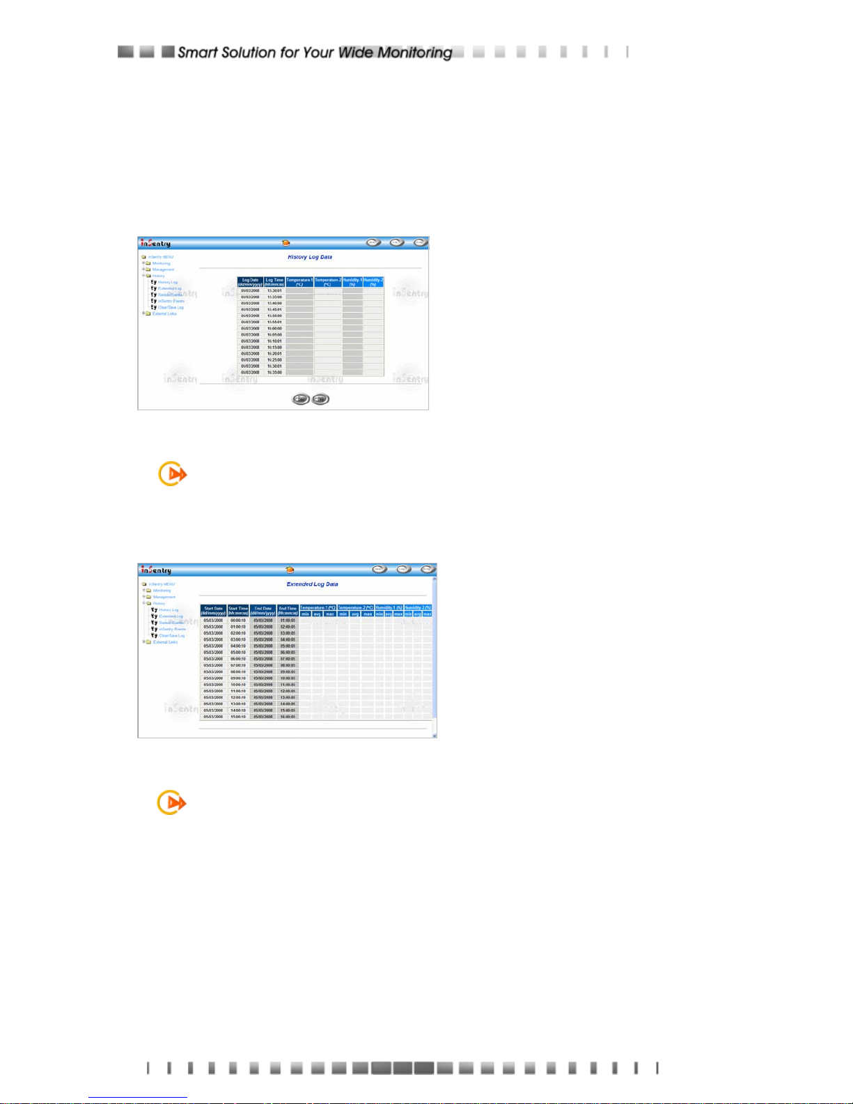
History Log
This page gives a snapshot of all
the fundamental EMD parameters.
The existing values are overwritten
when the maximum number of
entries (rows) has been reached.
Administrator has the access right
to delete the table entries.
Figure 3-16 History Log Data Screen
NOTE: To save the history log to a file in Microsoft Excel format, go to the Clear &
Save Log Data sub-menu and click on the link History Log under the Save Log
Data title bar.
Extended Log
This page gives a consolidated view
of the EMD parameters taken over a
period. For each of the EMD
parameters, minimum, maximum
and the average values are shown
in each of the records.
Figure 3-17 Extended Log Data Screen
NOTE: The Administrator can change the consolidation interval by changing the
value of the Extended Log Interval in inSentry Configuration page. The existing
log is overwritten when the maximum numbers of entries are reached
Page 31

31
Sensor Events
This page lists all the events that
have occurred since the table was
cleared. The existing values are
overwritten when the maximum
number of entries (rows) has been
reached.
Figure 3-18 Sensor Events Screen
inSentry Events
This page lists all the inSentry
events that have occurred since the
table wad cleared. The
Administrator has the access right
to delete the entries of the table.
Figure 3-19 inSentry Events Screen
Clear & Save Log Data
This page lets the Administrator
saves inSentry log data to a file in
Microsoft Excel format.
Administrator is also able to clear
specific log data or choose to clear
the log data after saving the log
data.
Figure 3-20 Clear& Save Log Screen
NOTE: When you mouse click any one of the hyper-link here while the "Clear the
corresponding log data as you click the hyper-link below" selection is set to
“Yes”, the corresponding log data will be lost eve n if you cancel the operation.
Page 32

32
4 - Monitoring inSentry via Java Monitor
inSentry provides three real-time graphical user interfaces written in Java applet to
give user an exceptional way to monitoring the EMD in LAN or WAN.
Java mon i tor: Display the EMD key parameters in graphic representation.
EMD History Log monitor: Display the EMD history log in graphic
representation.
EMD Extended History Log monitor: Display the EMD extended history
log in graphic representation.
4.1 Java Monitor
By clicking the Java button at the top right-hand side on the inSentry Home
Page, a Java Monitor will be open in a separate window. This monitor displays the
EMD key parameters – Temperature-1, Temperature-2, Humidity-1, Humidity-2 in
graphic representation. In addition, this monitor has a function icon, a status bar that
can display the current EMD status and an alarm window that can display the
current EMD alarms.
Figure 4-1 inSentry Java Monitor
Display switch-Two different display styles (Gauge or Overall Chart
presentation) of the EMD key parameters can be choosing from. This icon is
used to switch the display from gauge presentation to chart presentation and
Alarm windowFunction icon Status bar
Page 33

33
vice versa.
Poll Rate- Configure the poll rate that the Java monitors to get the next value
of the EMD parameters. Default is 5 seconds.
Event Message- Enable and disable display of the warning messages.
Exit- Exit from Java monitor.
Status Bar
Figure 4-2 Status Bar in Java Monitor
The status bar displays the current status of the EMD. “unknown” represent that
the EMD is in normal condition. If inSentry receives a status change of the EMD.
Alarm Windows
When inSentry receives a change in the status of it own or of the EMD, it displays
a specific message in the Alarm Window. This type of status change message is
an alarm. The Alarm Window displays the active alarms on the EMD and inSentry .
Page 34

34
4.2 History Log Monitor
By clicking the Java button at the top right-hand side on the inSentry Home
Page, a EMD History Log Monitor will be open in a separate window. This monitor
displays the EMD history log in line graph. By default, all the EMD parameters will
be display on the same graph.You can select any combination of the parameters to
be displayed on the graph by checking the check box beside each parameter on the
monitor screen and click the Refresh button.
Figure 4-3 EMD History Log Monitor
Display Point: Display the log interval on the graph
Refresh: Click the Refresh button after configures any setting on EMD History
Log Monitor to take effect
Reload: Update the EMD history log monitor and reset the right display
margin
Exit: Close the EMD History Log Monitor window
Right Display Margin
Left Display Margin
Right Margin Scroll Bar
Page 35

35
4.3 Extended History Log Monitor
By clicking the Java button at the top right-hand side on the inSentry Home
Page, a EMD Extended History Log Monitor will be open in a separate window. This
monitor displays the EMD extended history log in line graph. By default, all the EMD
parameters will be display on the same graph. You can select any combination of
the parameters to be displayed on the graph by checking the check box beside each
parameter on the monitor screen and click the Refresh button.
Figure 4-4 EMD Extended History Log Monitor
Display Point: Display the extended log interval on the graph
Refresh: Click the Refresh button after configures any setting on EMD
Extended History Log Monitor to take effect
Reload: Update the EMD history log monitor and reset the right display
margin
Exit: Close the EMD Extended History Log Monitor window
Right Display Margin
Left Display Margin
Right Margin Scroll Bar
Page 36

36
5 - Managing inSentry via SNMP
Setting SNMP parameters in inSentry If you intend to manage your inSentry/EMD
via SNMP NMS (Network Management station), you may want to customize some
of the SNMP settings (such as System Name, System Contact and System Location
and so on).
NOTE: Before using inSentry in SNMP environment, the IP address, gateway
must be configured properly. See Chapter 2 for details.
5.1 SNMP Access Control Setting
The inSentry supports SNMP protocol. You can use SNMP NMS to manage EMD
through the network. The IP address of the workstation must be entered in the
inSentry write access table to prevent unauthorized users from configuring inSentry
via HTTP or SNMP protocols.
NOTE: If you do not enter the IP address of the workstation to the Access Control
Table (via Serial Port or Telnet) or the SNMP/HTTP Access Control (via Web
Browser) in inSentry, the SNMP NMS can only view the EMD status; it will not be
able to perform any configuration on inSentry/EMD. (See Pg. 15 Access Control
Table Setting and Pg. 28 SNMP/HTTP Access Control for details.)
5.2 SNMP Trap Receivers Setting
See Pg. 36 SNMP Trap Receiver s for details.
5.3 Set up SNMP Manager Software
1. Add the MIB file of inSentry in the inSentry CD-ROM to the MIB database of
the SNMP manager.
2. Search for inSentry in the network
3. To access the inSentry SNMP agent, use ‘public’ for the GET community
string and the Read/Write password (default is admin) for the SET
community string.
GET Community string: public
SET Community string: admin
For more information, see the MIB file on the inSentry CD-ROM.
Page 37

37
Appendix A Technical Information
Technical Information about inSentry
Technical Specification
CPU 16-bits AC1105 Fast Ethernet RISC Processor Phoenix Kernel
Memory
2MB (1Mbit x16) TFBGA Flash ROM
2MB (1Mbit x16) SDRAM
Serial Communication Two asynchronous serial ports
LAN Chip Auto-Sense 10/100Mbps Fast Ethernet controller
Network Connection 10/100TX RJ-45 jack connector
RTC EPSON 4543
Network Protocol SNMP over UDP/IP
HTTP over TCP/IP
ARP, RARP, TFTP and ICMP
Supported MIB RFC1628
inSentry MIB
Operating
Temperature
0 ~ 40° C
Operating Humidity 10 ~ 80 %
Power Input 12V DC unregulated
Power Consumption 3.0 Watts Maximum
Size 138 mm x 88 mm x 30mm (L x W x H)
Weight 170gm
Regulatory
compliance
FCC class B, CE
Page 38

38
Diagram of Front Panel
STATUS LED
10/100 LAN LED
POWER LED
Diagram of Back Panel
1 2
TP
Connector
DIP
Switch
EMD-1
Port 0
EMD-2
Port 1
Reset
Button
Power
Inlet
Switch Description
DIP-switch definition
No. SW1 SW2 Function Mode
1 ON ON Manufacture Diagnostic Mode
2 ON OFF Reserved
3 OFF ON Reserved
4 OFF OFF Operating Mode
LED Indicator
LED definition
No. Traffic LED Status LED Function Mode
1 ON Flashing(1~3sec) Normal operation
2 Flashing(1sec) Flashing(1~3sec) Ethernet traffic
3 OFF Flashing(1~3sec) Ethernet disconnect
4 Two LED cross
Flashing
Two LED cross
Flashing
Auto Diagnostic Mode
5 OFF Flashing(1sec) Serial Upgrade Mode
6 ON or OFF ON Hardware error
Page 39

39
Serial Cable Definition
The Cable for EMD-1 &EMD-2 port of inSentry (Straight-Through CAT5 network cable)
RJ45 RJ45 COLOR
1 1 WHITE/ORANGE
2 2 ORANGE
3 3 WHITE/GREEN
4 4 BLUE
5 5 WHITE/BLUE
6 6 GREEN
7 7 WHITE/BROWN
8 8 BROWN
NOTE: Cable length not to exceed 20m/65.6ft.
The Cable for EMD-2 port of inSentry (PC cable)
RJ45 DB9 (Female) Description
1 - Not connected
3 2 Received Data from PC
4 5 Signal Ground
5 Case GND Chassis Ground
6 3 Transmitted Data to PC
8 - Not connected
NOTE: Pins 2 and 7 of the RJ45 connector are connected internally.
Page 40

40
Appendix B Firmware Upgrade
General information
To be able to perform firmware upgrading, inSentry must be connected to the same
network as the workstation from which the file is to be sent.
In the inSentry Control menu, check that the Network Upgrade is enabled and that
you have the login string information and the Community Read/Write Password.
Updating inSentry Firmware from Windows 9x/Me/NT
4.0/2000/XP
To perform firmware upgrade, use the iupgrade.exe program on the inSentry
CD-ROM. This program is compatible with Windows95/98/Me, Windows NT
3.51/4.0/2000/XP and higher.
1. Sensor Device List: Displays the addresses of the inSentry present in the
local network.
2. Discover: Search for the inSentry on the local network.
3. Add: Lets you add the IP address of a inSentry to the UPS List manually.
4. Modify: Lets you modify the parameters of the inSentry selected in the
inSentry List.
5. Upgrade: Sends the program loaded with the Open button to the selected
inSentry of the inSentry List.
6. Open: Open and load the new image file for upgrade.
7. Remove: Removes the selected inSentry from the inSentry List.
8. Quit: Exit the program.
NOTE: You can simultaneously upgrade up to 4 inSentrys on the network using
the iupgrade.exe program.
Page 41

41
Updating inSentry Firmware from UNIX
To be able to upgrade the firmware using a UNIX operating system, you must have
the command tftp installed in your system.
For uploading of the new firmware to inSentry, execute the following command line:
# tftp
tftp> binary
tftp> connect <host>
tftp> put <filename> upgrade@<password>@<username>
where:
binary : Binary data download mode
<host> : inSentry IP address.
Example 172.168.1.18
put : PUT command
<filename> : Name of the file containing the firmware image.
Example: /mnt/floppy/inSentry100.bin
upgrade : Upgrade key word
@ : Separator characters
<password>, <username> : User Name and Password for read/write access
 Loading...