

Page 1

Infoprint 6500 Series Line Matrix Printers
Ethernet Interface User’ s Manual
G550-0440-00
Page 2

Page 3

Infoprint 6500 Series Line Matrix Printers
Ethernet Interface User’ s Manual
G550-0440-00
Page 4

Note!
Before using this information and the product it supports, read the information in “Notices”
on page 5.
First Edition (May 2005)
Requests for IBM® publications should be made to your IBM
representative or to the IBM branch office serving your locality. If you
request publications from the address given below, your order will be
delayed because publications are not stocked here. Many of the IBM
Printing Systems Division publications are available from the web page
listed below.
Internet
Visit our home page at: http://www.ibm.com/printers
A Reader’s Comment form is provided at the back of this publication. If
the form has been removed, you can send comments by fax to
1-800-524-1519 (USA only) or 1-303-924-6873; by E-mail to
printpub@us.ibm.com; or by mail to:
IBM Printing Systems Division
Department H7FE Building 004N
Information Development
PO Box 1900
Boulder CO 80301-9191 USA
IBM may use or distribute whatever information you supply in any way it
believes appropriate without incurring any oblication to you.
© Copyright International Business Machines Corporation 2005. All
rights reserved.
US Government Users Restricted Rights – Use, duplication or disclosure
restricted by GSA ADP Schedule Contract with IBM Corp.
Page 5

Notices
Energy Star
The Environmental Protection Agency ENERGY STAR® Computers
program is a partnership effort with manufacturers of data
processing equipment to promote the introduction of energyefficient personal computers, monitors, printers, fax machines, and
copiers to help reduce air pollution and global warming caused by
electricity generation.
IBM Printing Systems Company participates in this program by
introducing printers that reduce power consumption when they are
not being used. As an E
Systems Company has determined that this product meets the
NERGY STAR
E
®
guidelines for energy efficiency.
NERGY STAR
®
Partner, IBM Printing
NOTE: The E
endorsement of any product or service.
NERGY STAR
®
emblem does not represent EPA
Page 6

Notices
This information was developed for products and services offered in
the U.S.A.
®
may not offer the products, services, or features discussed in
IBM
this document in other countries. Consult your IBM representative
for information on the products and services currently available in
your area. Any reference to an IBM product, program, or service is
not intended to state or imply that only that IBM product, program,
or service may be used. Any functionally equivalent product,
program, or service that does not infringe any IBM intellectual
property rights may be used instead. However, it is the user’s
responsibility to evaluate and verify the operation of any non-IBM
product, program, or service.
IBM may have patents or pending patent applications covering
subject matter described in this document. The furnishing of this
document does not give you any license to these patents. You can
send license inquires, in writing, to:
IBM Director of Licensing
IBM Corporation
North Castle Drive
Armonk, NY 10504-1785 U.S.A.
The following paragraph does not apply to the United Kingdom
or any other country where such provisions are inconsistent
with local law:
INTERNATIONAL BUSINESS MACHINES CORPORATION
PROVIDES THIS PUBLICATION “AS IS” WITHOUT WARRANTY
OF ANY KIND, EITHER EXPRESS OR IMPLIED, INCLUDING,
BUT NOT LIMITED TO, THE IMPLIED WARRANTIES OF
NON-INFRINGEMENT, MERCHANTABILITY OR FITNESS FOR A
PARTICULAR PURPOSE. Some states do not allow disclaimer of
express or implied warranties in certain transactions, therefore, this
statement may not apply to you.
Page 7

This information could include technical inaccuracies or
typographical errors. Changes are periodically made to the
information herein; these changes will be incorporated in new
editions of the publication. IBM may make improvements and/or
changes in the product(s) described in this publication at any time
without notice.
Any references in this information to non-IBM Web sites are
provided for convenience only and do not in any manner serve as
an endorsement of those Web sites. The materials at those Web
sites are not part of the materials for this IBM product and use of
those Web sites is at your own risk.
IBM may use or distribute any of the information you supply in any
way it believes appropriate without incurring any obligation to you.
All models of the printer meet the requirements of IEC 950, First
Edition, Amendments 1 and 2. The laser used in the printer
complies with IEC 825 and EN 60825.
Any performance data contained herein was determined in a
controlled environment. Therefore, the results obtained in other
operating environments may vary significantly. Some
measurements may have been made on development-level
systems and there is no guarantee that these measurements will be
the same on generally available systems. Furthermore, some
measurement may have been estimated through extrapolation.
Actual results may vary. Users of this document should verify the
applicable data for their specific environment.
Information concerning non-IBM products was obtained from the
suppliers of those products, their published announcements or
other pubicly available sources. IBM has not tested those products
and cannot confirm the accuracy of performance, compatibility or
any other claims related to non-IBM products. Questions on the
capabilities of non-IBM products should be addressed to the
suppliers of those products.
Page 8

IBM encourages owners of information technology (IT) equipment
to responsibly recycle their equipment when it is no longer needed.
IBM offers a variety of programs and services to assist equipment
owners in recycling their IT products. Information on these product
recycling offerings can be found on IBM’s Internet site at
http://www.ibm.com/ibm/environment/products/prp.shtml.
All statements regarding IBM’s future direction or intent are subject
to change or withdrawal without notice, and represent goals and
objectives only.
All IBM prices shown are IBM’s suggested retail prices, are current
and are subject to change without notice. Dealer prices may vary.
Note!
Before using this information and the product it supports, read the information and
Communication Statements in “Notices” on page 5.
If you are viewing this information softcopy, the photographs and
color illustrations may not appear.
For online versions of this book, we authorize you to:
• Copy, modify, and print the documentation contained on the
media, for use within your enterprise, provided you reproduce
the copyright notice, all warning statements, and other required
statements on each copy or partial copy.
• Transfer the original unaltered copy of the documentation when
you transfer the related IBM product (which may be either
machines you own, or programs, if the program’s license terms
permit a transfer). You must, at the same time, destroy all other
copies of the documentation.
You are responsible for payment of any taxes, including personal
property taxes, resulting from this authorization.
Your failure to comply with the terms above terminates this
authorization. Upon termination, you must destroy your machine
readable documentation.
Page 9

Trademarks
The following terms, used in this publication, are trademarks of the
IBM corporation in the United States or other countries or both:
AFCCU; iSeries
AFP Micro Channel
Advanced Function Presentation z/OS
AIX
®
System/370
AIX/6000 S/370
AS/400
®
BCOCA Personal System/2
OS/2
®
®
Bar Code Object Content Architecture Print Services Facility
ESCON
®
pSeries
ES/3090 PSF
ES/4381 PS/2
ES/9000 RISC System/6000
®
®
ES/9370 XGA
IBM
®
zSeries
®
InfoPrint
IPDS
C-bus is a trademark of Collary, Inc. in the United States, other
countries, or both.
Java and all Java-based trademarks and logos are trademarks or
registered trademarks of Sun Microsystems, Inc. in the United
States, other countries, or both.
Microsoft, Windows, Windows NT, and Windows logo are
trademarks of Microsoft Corporation in the United States, other
countries, or both.
PC Direct is a trademark of Ziff Communications Company in the
United States, other countries, or both and is used by IBM
Corporation under license.
ActionMedia, LANDesk, MMX, Pentium and ProShare are
trademarks of Intel Corporation in the United States, other
countries, or both. (For a complete list of Intel trademarks, see
www.intel.com/tradmarx.htm.)
Page 10

Unix is a registered trademark of The Open Group in the United
States and other countries.
SET and SET Logo are trademarks owned by SET Secure
Electronic Transaction LLC. (For further information, see
www.setco.org/aboutmark.html.)
zSeries is a trademark of IBM.
Other company, product, or service names may be the trademarks
or service marks of others.
Product Recycling and Disposal
This unit may have lead-containing materials – such as circuit
boards and connectors – that require special handling. Before this
unit is disposed of, these materials must be removed and recycled
or discarded according to applicable regulations. This book
contains specific information on batteries and refrigerant where
applicable.
This product may contain a sealed, lead-acid battery; lithium
battery; nickel-metal-hydride battery; or nickel-cadium battery.
Batteries of these types must be recycled or disposed of properly.
Recycling facilities may not be available in your area.
In the United States, IBM has established a collection process for
reuse, recycling, or proper disposal of used batteries and batter
packs from IBM equipment. For information on proper disposal of
the batteries in this product, please contact IBM at 1-800-426-4333.
For information on disposal of batteries outside the United States,
contact your local waste disposal facility.
Page 11

Communication Statements
Federal Communications Commission (FCC)
Statement
This equpment has been tested and found to comply with the limits
for a Class A digital device, pursuant to Part 15 of the FCC Rules.
These limits are designed to provide reasonable protection against
harmful interference when the equipment is operated in a
commercial environment. This equipment generates, uses, and can
radiate radio frequency energy and, if not installed and used in
accordance with the instructions, may cause harmful interference to
radio communications. Operation of this equipment in a residential
area is likely to cause harmful interference in which case the user
will be required to correct the interference at his own expense.
Properly shielded and grounded cables and connectors must be
used in order to meet FCC emission limits. IBM is not responsible
for any radio or television interference caused by using other than
recommended cables and connectors or by unauthorized changes
or modifications to this equipment. Unauthorized changes or
modifications could void the user’s authority to operate the
equipment.
This device complies with Part 15 of the FCC Fules. Operation is
subject to the following two conditions: (1) this device may not
cause harmful interference, and (2) this device must accept any
interference received, including interference that may cause
undesired operation.
Page 12

European Union (EU) Conformity Statement
Hereby, IBM declares that this product is
in complicance with the essential
requirements and other relevent
provisions of Directive 1999/5/EC.
IBM cannot accept responsibility for any failure to satisfy the
protection requirements resulting from a non-recommended
modification of the product, including the fitting of non-IBM option
cards.
This product has been tested and found to comply with the limits for
Class A Information Technology Equipment according to European
standard EN 55022. The limits for Class A equipment were derived
for commercial and industrial environments to provide reasonable
protection against interference with licensed communication
devices.
WARNING
This is a Class A product. In a domestic environment this product may cause radio
interference in which case the user may be required to take adequate measures.
Properly shielded and grounded cables and connectors must be
used in order to reduce the potential for causing interference to
radio and TV communications and to other electrical or electronic
equipment. IBM cannot accept responsibility for any interference
caused by using other than recommended cables and connectors.
Industry Canada Compliance Statement
This Class A digital apparatus complies with Canadian ICES-003.
Cet appareil numérique de la classe A conform á la norme
NMB-003 du Canada.
Page 13

Statement of CISPR 22 Edition 2 Compliance
Attention: This is a Class A Product. In a domestic environment
this product may cause radio interference in which case the user
may be required to take adequate measures.
Japanese VCCI Class A
Japan JEITA Statement
533
Page 14

German Conformity Statement
Handbuchtexte: FCC class A entspricht: EMVG Klasse A
Text Für alle in Deutschland vertriebenen EN 55022 Klasse A
Geräte:
Zulassungsbescheinigung laut dem Deutschen Gesetz über die
elektromagnetische Verträglichkeit von Geräten (EMVG) vom 18.
September 1998 (bzw. der EMC EG Richtlinie 89/336):
Dieses Gerät ist berechtigt in Übereinstimmung mit dem Deutschen
EMVG das EG-Konformitätszeichen - CE - zu führen.
Verantwortlich für die Konformitätserklärung nach Paragraph 5 des
EMVG ist die: IBM Deutschland GmbH, 70548 Stuttgart.
Informationen in Hinsicht EMVG Paragraph 4 Abs. (1) 4:
Das Gerät erfüllt die Schutzanforderungen nach EN 55024 und EN
55022 Klasse A.
EN 55022 Klasse A Geräte müssen mit folgendem Warnhinweis
versehen werden: “Warnung: dies ist eine Einrichtung der Klasse A.
Diese Einrichtung kann im Wohnbereich Funkstörungen
verursachen; in diesem Fall kann vom Betreiber verlangt werden,
angemessene Maßnahmen durchzuführen und dafür
aufzukommen.”
EN 55024 Hinweis:
Wird dieses Gerät in einer industriellen Umgebung betrieben (wie in
EN 55024 festgelegt), dann kann es dabei eventuell gestört
werden. In solch einem Fall ist der Abstand bzw. die Abschirmung
zu der industriellen Störquelle zu öergrvßern.
Anmerkung:
Um die Einhaltung des EMVG sicherzustellen sind die Geräte, wie
in den IBM Handbüchern angegeben, zu installieren und zu
betreiben.
Page 15

China
Declaration:
This is a Class A product. In a domestic environment this product
may cause radio interference in which case the user may need to
perform practical actions.
Page 16

Taiwannese
Warning:
This is a Class A product. In a domestic environment this product
may cause radio interference in which case the user will be
required to take adequate measures.
Page 17

Korea
CAUTION:
This product is equipped with a 3-wire power cord and plug for the
user’s safety. Use this power cord in conjunction with a properly
grounded electrical outlet to avoid electrical shock.
Lithium Battery Warning
The controller board contains a lithium battery sealed inside the
real-time clock chip. Do not disassemble the chip to replace the
battery. Do not dispose of the chip by incineration. Failure to
comply may cause the battery to explode. Contact your local waste
agency for the correct disposal procedure.
Page 18

Software License Agreement
Your printer contains, among other software, Printronix operating
software including, but not limited to the Embedded Configurable
Operating System (the “eCos Software”) as embedded software.
The terms of this Agreement apply only to the eCos Software, and
all other embedded software supplied with the printer. You accept
the terms of this Agreement by your initial use of your printer.
1. Object Code License.
Printronix grants you a nonexclusive license to use the Printronix
Software, the eCos Software and all other embedded software
(collectively, the “Embedded Software” or the “Software”) only in
conjunction with the printer. As the rightful possessor of the printer,
you may make a reasonable number of copies of the Software as
necessary for backup, configuration, and restoration of the printer.
You must reproduce the copyright notice and any other legend of
ownership on each copy of the Software you make.
You may transfer possession of the Software and its media to
another party only with the transfer of the printer on which the
Software is used. If you do so, you must give the other party a copy
of these terms and provide all user documentation to that party.
When you do so, you must destroy any copies of Software not
resident in the printer.
Your license for the Software terminates when you no longer
rightfully possess the printer. No other rights under this license are
granted.
2. Source Code
A source code version of eCos Software is available under the
terms of the Red Hat eCos Public License v1.1 at
www.printronix.com. Printronix grants no rights whatsoever in the
source code for the Printronix Software.
Page 19

3. No Warranty
THE EMBEDDED SOFTWARE IS PROVIDED UNDER THIS
LICENSE ON AN "AS IS" BASIS, WITHOUT WARRANTY OF ANY
KIND, EITHER EXPRESSED OR IMPLIED, INCLUDING,
WITHOUT LIMITATION, WARRANTIES THAT THE EMBEDDED
SOFTWARE IS FREE OF DEFECTS, MERCHANTABLE, FIT FOR
A PARTICULAR PURPOSE OR NON-INFRINGING. THE ENTIRE
RISK AS TO THE QUALITY AND PERFORMANCE OF THE
EMBEDDED SOFTWARE IS WITH YOU. SHOULD ANY OF THE
EMBEDDED SOFTWARE PROVE DEFECTIVE IN ANY
RESPECT, YOU (NOT RED HAT, PRINTRONIX, ANY OTHER
CONTRIBUTOR OR ANY DISTRIBUTOR) ASSUME THE COST
OF ANY NECESSARY SERVICING, REPAIR OR CORRECTION.
THIS DISCLAIMER OF WARRANTY CONSTITUTES AN
ESSENTIAL PART OF THIS LICENSE. NO USE OF ANY OF THE
EMBEDDED SOFTWARE IS AUTHORIZED HEREUNDER
EXCEPT UNDER THIS DISCLAIMER.
4. Conflicting Terms
You agree that this Agreement provides you no more rights with
regards to warranty, support, indemnity or liability terms with
respect to Red Hat, Inc., Printronix, Inc. or any contributor to the
Embedded Software than that provided by the Red Hat eCos Public
License v.1.1 or any express warranty that may be made by
Printronix, Inc.
Page 20

5. Limitation of Liability
UNDER NO CIRCUMSTANCES AND UNDER NO LEGAL
THEORY, WHETHER TORT (INCLUDING NEGLIGENCE),
CONTRACT, OR OTHERWISE, SHALL RED HAT, PRINTRONIX,
ANY OTHER CONTRIBUTOR, OR ANY DISTRIBUTOR OF THE
EMBEDDED SOFTWARE, OR ANY PART THEREOF, OR ANY
SUPPLIER OF ANY OF SUCH PARTIES, BE LIABLE TO YOU OR
ANY OTHER PERSON FOR ANY INDIRECT, SPECIAL,
INCIDENTAL, OR CONSEQUENTIAL DAMAGES OF ANY
CHARACTER INCLUDING, WITHOUT LIMITATION, DAMAGES
FOR LOSS OF GOODWILL, WORK STOPPAGE, COMPUTER
FAILURE OR MALFUNCTION, OR ANY AND ALL OTHER
COMMERCIAL DAMAGES OR LOSSES, EVEN IF SUCH PARTY
SHALL HAVE BEEN INFORMED OF THE POSSIBILITY OF SUCH
DAMAGES. THIS LIMITATION OF LIABILITY SHALL NOT APPLY
TO LIABILITY FOR DEATH OR PERSONAL INJURY RESULTING
FROM SUCH PARTY'S NEGLIGENCE TO THE EXTENT
APPLICABLE LAW PROHIBITS SUCH LIMITATION. SOME
JURISDICTIONS DO NOT ALLOW THE EXCLUSION OR
LIMITATION OF INCIDENTAL OR CONSEQUENTIAL DAMAGES,
SO THAT EXCLUSION AND LIMITATION MAY NOT APPLY TO
YOU.
6. U.S. Government Users
The Embedded Software is a "commercial item," as that term is
defined in 48 C.F.R. 2.101 (Oct. 1995), consisting of "commercial
computer software" and "commercial computer software
documentation," as such terms are used in 48 C.F.R. 12.212 (Sept.
1995). Consistent with 48 C.F.R. 12.212 and 48 C.F.R. 227.7202-1
through 227.7202-4 (June 1995), all U.S. Government End Users
acquire Covered Code with only those rights set forth herein.
Page 21

7. Miscellaneous
This Agreement represents the complete agreement concerning
subject matter hereof. If any provision of this Agreement is held to
be unenforceable, such provision shall be reformed only to the
extent necessary to make it enforceable. This Agreement shall be
governed by California law provisions (except to the extent
applicable law, if any, provides otherwise), excluding its conflict-oflaw provisions.
8. Red Hat Statement with regards to eCos Software
Part of the software embedded in this product is eCos - Embedded
Configurable Operating System, a trademark of Red Hat. Portions
created by Red Hat are Copyright (C) 1998, 1999, 2000 Red Hat,
Inc.
(http://www.redhat.com) All Rights Reserved.
THE SOFTWARE IN THIS PRODUCT WAS IN PART PROVIDED
BY RED HAT AND ANY EXPRESS OR IMPLIED WARRANTIES,
INCLUDING, BUT NOT LIMITED TO, THE IMPLIED
WARRANTIES OF MERCHANTABILITY AND FITNESS FOR A
PARTICULAR PURPOSE ARE DISCLAIMED. IN NO EVENT
SHALL THE AUTHOR BE LIABLE FOR ANY DIRECT, INDIRECT,
INCIDENTAL, SPECIAL, EXEMPLARY, OR CONSEQUENTIAL
DAMAGES (INCLUDING, BUT NOT LIMITED TO,
PROCUREMENT OF SUBSTITUTE GOODS OR SERVICES;
LOSS OF USE, DATA, OR PROFITS; OR BUSINESS
INTERRUPTION) HOWEVER CAUSED AND ON ANY THEORY
OF LIABILITY, WHETHER IN CONTRACT, STRICT LIABILITY,
OR TORT (INCLUDING NEGLIGENCE OR OTHERWISE)
ARISING IN ANY WAY OUT OF THE USE OF THIS SOFTWARE,
EVEN IF ADVISED OF THE POSSIBILITY OF SUCH DAMAGE.
Page 22

Product Registration Information
Special Offers at the
IBM Product Registration Web site
By registering your printer or multifunction device with IBM today:
• Take advantage of special offers
• Registration is quick, easy and on-line
• Quick links to other IBM on-line sites: new promotions, drivers,
software, and more!
Register your new IBM printer today:
www.ibm.com/printers/register
N’attendez pas! Enregistrez votre nouvelle imprimante ou votre
dispositif multifunction sur www.ibm.com/printers/register
Jetzt registristrieen! Registrieren Sie Ihren neuen IBM Drucker oder
Ihr neues Multifunktionsgerät. Registrieren Sie Ihren:
www.ibm.com/printers/register
Registra subito la tua nuova stampante sul sito: www.ibm.com/
printers/register
¡Registtresse ahora! Registre su nueva impresora IBM, o su nueva
opción multifunctional en: www.ibm.com/printers/register
Registreer nu! Registreer uw nieuwe printer of multifunktionele
apparaten op www.ibm.com/printers/register
Registe agora! Registe a sua nova impressora ou o seu novo
equipamento multifuncional IBM em:
www.ibm.com/printers/register
Page 23

www.ibm.com/printers/register
Page 24

Page 25

Table of Contents
1 Introduction .............................................. 35
Overview ...............................................................................35
What Is The Ethernet Interface? ......................................35
Printer Models And Applicable Ethernet Interface
Cards................................................................................36
What Special Features Are Available?.............................36
Logical Printer Architecture ...................................................38
Destinations/Queues........................................................40
Models..............................................................................40
Interfaces...............................................................................42
10/100Base-T...................................................................42
Speed Setting for 10/100Base-T......................................47
Conventions Used In This Manual ........................................48
Notes And Notices.................................................................49
2 Installation And Configuration .................. 51
Installation .............................................................................51
Connecting To The Network ............................................51
Configuration Tools ...............................................................52
Configuration Using The Control Panel............................53
Ethernet Interface Verification..........................................57
Wireless Ethernet Interface Configuration Using
The Control Panel ............................................................58
Wireless Cisco LEAP .......................................................66
Kerberos Enabled Wireless NIC Configuration ................67
HTML Forms ....................................................................69
Configuration Alternatives................................................72
Page 26

Table of Contents
3 Embedded Ethernet Interface Web
Page ......................................................... 73
Overview ...............................................................................73
Configuration .........................................................................74
Network Configuration........................................................... 76
TCP/IP Network ...............................................................76
802.11b ............................................................................78
Windows Network (NetBIOS TCP/IP) ..............................81
Novell Network .................................................................82
Print Path Configuration ........................................................84
Destination Settings .........................................................84
Current Model Settings ....................................................86
Current Log Path Settings................................................87
Print Model Configuration...................................................... 88
Log Path Configuration .........................................................91
TN5250/3270 Configuration ..................................................93
SNMP Configuration .............................................................97
Administration Configuration ...............................................105
System Information ........................................................105
Passwords .....................................................................108
System Configuration..........................................................108
Status ..................................................................................109
Status - I/O Port .............................................................109
Status - Network ............................................................110
IBM Printing Systems ..........................................................110
Page 27

Table of Contents
4 Windows Configuration .......................... 111
Overview .............................................................................111
Windows Environment Description......................................111
Windows Ethernet Interface Configuration..........................112
Mandatory ......................................................................112
Optional..........................................................................112
Configuration Using ARP ...............................................112
Communicating Across Routers.....................................114
Changing Workgroup Names.........................................115
Changing Destination Names ........................................116
Windows Host Configuration ...............................................118
Windows XP/2000 Host Setup .......................................118
Windows NT 4.0 Host Setup ..........................................126
Windows NT 3.51 Host Setup ........................................131
Windows Me or 9x Host Setup .......................................132
Windows Troubleshooting Tips ...........................................134
Technical Support ..........................................................134
Ethernet Interface Cannot Be Found On
The Network...................................................................134
HTML Configuration Forms Will Not Display..................135
Errors Occur When Defining An LPR Printer .................135
Cannot Browse The Ethernet Interface On
The Network...................................................................136
Printer Errors When Printing Or No Output....................136
TCP/IP Access Problem.................................................137
Web Browser/HTTP Problem .........................................139
Windows NT 4.0 Or 2000 Host Setup Problems............139
Page 28

Table of Contents
5 AIX/Unix Configuration ........................... 143
Overview .............................................................................143
Unix Environment Description .............................................143
Unix Ethernet Interface Configuration .................................144
Mandatory ......................................................................144
Optional..........................................................................144
Using ARP .....................................................................144
Using RARP ...................................................................146
Using BOOTP ................................................................147
Communicating Across Routers.....................................148
Unix Host Configuration ......................................................149
Manual System V Host Setup ........................................149
Ethernet Installation on HP-UX ...........................................150
Solaris 2.6 – 7 Ethernet Setup ............................................151
SCO Setup ..........................................................................152
Manual LPR/LPD Host Setup.........................................159
Ethernet Configuration for AIX 4 ....................................161
AIX Remote Queue Time–Out Setting...........................163
Printing With FTP ...........................................................163
Direct Socket Printing.....................................................165
Printing From AIX ................................................................165
Setting Up AIX 4.x..........................................................166
Unix Troubleshooting Tips ..................................................167
Ethernet Interface Cannot Be Found On
The Network...................................................................167
Nothing Prints ................................................................168
Stair-Stepped Output .....................................................169
No Form Feed Or Extra Page Comes Out.....................170
TCP/IP Access Problem.................................................170
Front Panel Message - Dynamically Set Params
Read Only ......................................................................172
Page 29

Table of Contents
6 Novell Configuration............................... 173
Overview .............................................................................173
Novell Environment Description ..........................................173
Novell Ethernet Interface Configuration ..............................174
Using HTML Forms ........................................................175
Novell Host Configuration....................................................176
NetWare Version 3.x PSERVER Setup .........................176
NetWare Version 3.x RPRINTER Setup ........................179
NetWare Version 4.x and 5.x PSERVER Setup.............182
NetWare Version 4.x and 5.x RPRINTER Setup ...........185
Novell Troubleshooting Tips ................................................187
NetWare 3.x - No PSERVER Connection ......................188
NetWare 4.x and 5.x- No PSERVER Connection ..........189
7 Novell Configuration For
10/100Base-T Interfaces........................ 191
Overview .............................................................................191
Novell Ethernet Interface Configuration (10/100Base-T) ....192
Preferred File Server (NDS and Bindery Setups) ..........192
Setting Password Security
(NDS and Bindery Setups).............................................195
Adjusting Polling Time (NDS and Bindery Setups) ........197
Changing The Ethernet Interface Name
(NDS and Bindery Setups).............................................198
Changing The Ethernet Interface Frame Type
(NDS and Bindery Setups).............................................200
Changing The Ethernet Interface Mode
(NDS and Bindery Setups).............................................201
Setting The Ethernet Interface NDS Context
(NDS Setups) .................................................................202
Setting The Ethernet Interface Preferred NDS Tree
(NDS Setups) .................................................................203
Page 30

Table of Contents
Novell Host Configuration (10/100Base-T) .........................204
NDS PSERVER Setup (Netware 4.x/5.x).......................205
Bindery PSERVER Setup
(Netware 3.x, Netware 4.x, and Netware 5.x) ................208
Referencing A Bindery Queue In NDS
(Netware 3.x, Netware 4.x, and Netware 5.x) ................208
RPRINTER/NPRINTER Setup
(Netware 3.x, Netware 4.x, and Netware 5.x) ................209
NDPS Configuration (Netware 4.11 and Above)............212
Troubleshooting (10/100Base-T) ........................................215
PSERVER Setup ...........................................................215
RPRINTER/NPRINTER Setup .......................................218
Printing Related .............................................................220
8 iSeries Configuration, ASCII Printer ....... 223
Overview .............................................................................223
Configuring iSeries For ASCII Using TCP/IP ......................225
Configuring With ADDTCPIFC.......................................225
Configuring A Router Definition With ADDTCPRTE ......227
Configuring A Local Domain And Hostname..................227
Configuring A TCP/IP Host Table Entry .........................228
Configuring The iSeries For Printing ...................................228
Setting Up Printing For ASCII Files................................228
Verify Printing On iSeries ....................................................236
iSeries ASCII Troubleshooting ............................................237
TCP/IP Access Problem.................................................238
Web Browser/HTTP Problem.........................................240
Page 31

Table of Contents
9 iSeries Configuration, IPDS Printer........ 241
Configuring On iSeries As An IPDS Printer.........................241
Printing AFP, IPDS, And SCS Files ...............................241
Requirements.................................................................242
Configuration Checklist ..................................................242
Configuring An iSeries TCP/IP Interface With
ADDTCPIFC...................................................................243
Configuring PSF For IPDS On V3R7 Or V4R1 ..............246
Configuring PSF for IPDS On V4R2 And Above............252
Verifying The IPDS Configuration On iSeries......................259
Sharing The iSeries Printer On The Network ......................260
Printer Sharing Parameters............................................261
iSeries Troubleshooting.......................................................262
Cannot PING The Printer ...............................................262
PSF Terminates When Initialized...................................263
Spooled Print File Remains In PND Status....................263
Spooled Files Disappear Without Printing......................264
Data Is Being Clipped ....................................................264
10 z/OS Configuration, IPDS Printer........... 265
Overview .............................................................................265
Requirements.................................................................265
Configuration Checklist ..................................................266
Configuring PSF for z/OS to Print IPDS Files .....................267
Configuration Procedure ................................................267
Verifying a TCP/IP-Attached Printer on z/OS.................277
Sharing IBM 6500-v Printers on z/OS .................................278
JES Spool Printer Sharing .............................................278
Port Switching Printer Sharing .......................................280
Handling z/OS Connectivity Problems ................................280
Ping is Not Successful ...................................................280
Ping is Successful ..........................................................281
Page 32

Table of Contents
11 z/OS Configuration, TN3270E................ 283
z/OS Configuration For A TN3270E Printer ........................283
Coax Printer Support FMID .................................................283
Program Materials ...............................................................284
VTAM Definitions For SCS and DSE TN3270E .............285
TCPIP Configuration With TN3270E..............................287
Printer Inventory Manager As Defined With TN3270E...288
Configuration Screens.........................................................297
12 iSeries Configuration, TN5250 ............... 301
Setting Up TN5250 Print Queues on iSeries.......................301
Setting Up A TN5250 Connection/Device Via A
Telnet Session ....................................................................302
User Supplied Values ....................................................303
Using Telnet Commands for TN5250..................................303
Command List ................................................................303
Getting Started...............................................................304
TN5250 Job Formatting ......................................................305
Font Identifier (FONT) - Help ..............................................307
13 ISeries Configuration, SNMP ................. 309
Configuring for a *LAN 3812 SNMP Device Description.....309
Configuration Instructions ..............................................309
Varying on the Printer ....................................................315
Problem Areas for Consideration ...................................316
Additional Information ....................................................317
Page 33

Table of Contents
14 Monitoring Printers ................................. 319
Implementing Printer Management .....................................319
Agent/Manager Model....................................................319
MIB.................................................................................320
SNMP.............................................................................322
Monitoring Tools..................................................................322
Monitoring With AIX NetView/6000 ................................322
Setting The SNMP Community Name............................323
The Printer Management Utility Software (PMU) ...........323
15 IBM Network Printer Manager................ 325
Overview .............................................................................325
16 Commands ............................................. 327
Command Shell Overview ...................................................327
npsh Access Methods ....................................................327
Main npsh Command Prefixes.......................................327
Getting Command Help..................................................328
Complete Command List.....................................................328
Store Commands ...........................................................329
Set Commands ..............................................................344
List Commands ..............................................................356
Miscellaneous Commands.............................................360
17 Extra Features........................................ 365
Ethernet Interface Security..................................................365
Users And Passwords....................................................365
Reset The Ethernet Password .......................................367
TCP Access Lists ...........................................................369
Printer Monitoring And Logging...........................................371
Printer And Print Job Monitoring ....................................371
Printer Logging Through Logpaths.................................372
Ethernet Interface Naming Schemes ..................................373
Page 34

Table of Contents
Glossary ................................................. 375
Page 35

1 Introduction
Overview
This chapter introduces you to the Ethernet Interface architecture
and special features, as well as providing information on installation
and configuration tools.
What Is The Ethernet Interface?
The Ethernet Interface allows you to attach printers on a local area
network (LAN) rather than attaching them directly to a host system.
Following simple configuration steps, these peripherals can be
simultaneously shared with users on the network whether you are
using TCP/IP, NetBIOS over TCP/IP, or IPX (Novell
The Ethernet Interface package contains an Ethernet Interface to
attach itself and the printer to the network. The Ethernet Interface is
supplied in one of four forms:
®
).
• an Ethernet adapter attached to the printer parallel port
• a wireless Ethernet adapter
• an integrated Ethernet card
• an integrated wireless Ethernet card.
Throughout this manual, features specific to each Ethernet
Interface type will be indicated by the sideheads ADAPTER,
WIRELESS ADAPTER, ETHERNET, and WIRELESS.
35
Page 36

Chapter 1 Overview
Printer Models And Applicable Ethernet Interface Cards
The following lists the 6500-v printer model with its corresponding
Ethernet Interface Card type.
Printer Ethernet Interface Card Type
6500-v Power PC Based PCI Ethernet (wired)
Power PC Based PCI Ethernet (wireless)
External Ethernet to Parallel Port
1
This is the IBM Network Print Server which is available through IBM. This feature is
offered with limited support. The information in this manual does not apply to the IBM
Network Print Server. Contact your IBM representative for more details.
1
What Special Features Are Available?
36
The Ethernet Interface offers an extensive list of features including:
• built-in HTML forms for easy cross-platform configuration
• availability of remote management software (IBM Printer
Management Utility)
• a detailed and easy-to-use command shell built-in to the
firmware
• multi-level configuration security through passwords,
permission levels, and access lists
• WAN-wide communication access
• numerous printer logging methods (e.g., automatic email) to
record printer errors and usage
• remote management through HTML forms, Telnet sessions,
rsh/rcmd/remsh commands, SNMP, and pre-defined log
methods
• extensive built-in troubleshooting tools
• built-in telnet and ping clients
Page 37

What Special Features Are Available?
• configurable memory usage by disabling protocols and
destination services
• multiple destinations/queues for versatile printer manipulation
and distinct print setups
• header and trailer strings to instruct printers on font, pitch,
printing, etc.
• flexible naming conventions
• automatic network connection and frame type sensing
• simultaneous printing across all I/O ports and all supported
protocols
• multiple network protocol support
37
Page 38

Chapter 1 Logical Printer Architecture
Logical Printer Architecture
The Ethernet Interface implements a logical printer architecture
which gives the system administrator the possibility to configure the
print server to handle and act upon the print data in several ways.
When a print job comes through the print server, there is a certain
logical print path that it follows before it gets to the printer. Each
logical print path consists of a sequence of logical steps where
extra processing may be performed on the print data before it is
sent to the printer. This ability to preprocess the print data before it
is sent to the printer allows elimination of certain printing problems,
or implementation of printer enhancements that may be difficult and
time consuming to solve or introduce at the system, spool file or
queue level. The preprocess ability is also simplistic to perform at
the print server level.
NOTE: If the printer is configured for IPDS, any reference to
“d4prn” should be understood to mean “dipdsprn.” This
queue should only be used to print IPDS.
38
The logical print path for a print job going through the Ethernet
Interface consists of three different phases:
• Phase 1 - the host sends the job to a destination or queue on
the Ethernet Interface (e.g. d1prn).
• Phase 2 - the print job passes through the associated “model”
(e.g. model “m1”) on the Ethernet Interface for any extra
processing associated with the model.
• Phase 3 - the processed print job is directed to the printer for
output.
Page 39

What Special Features Are Available?
Logical Printer Architecture
Phase 1 Phase 2 Phase 3
Host
Destination 1
(d1prn)
Destination 2
(d2prn)
Destination 3
(d3prn)
Destination 4
(d4prn)
Destination 5
(d5prn)
Destination 6
(d6prn)
Model 1
(m1)
Model 2
(m2)
Model 3
(m3)
Model 4
(m4)
Printer
Model 5
(m5)
Model 6
(m6)
Destination 7
(d7prn)
Destination 8
(d8prn)
Figure 1. Print Path
Model 7
(m7)
Model 8
(m8)
39
Page 40

Chapter 1 Logical Printer Architecture
Destinations/Queues
For every I/O port on the Ethernet Interface, there is at least one
pre-defined logical print queue or destination to accept print jobs
destined for it. This includes print job that is sent directly to the I/O
port, such as port 9100. These queue or destination names are predefined but can be changed by the user.
Models
For every destination or queue, there is a pre-defined model
associated with it. The model defines how the print job will be
processed as it passes through to the printer. Models are a set of
mini filters that can be used to modify the print data stream. The
functions available for each model are as follows:
1. Insert carriage return after line feed
2. Insert a banner page before or after each print job
3. Insert header strings to
40
• Print in landscape mode
• Print in portrait mode
4. Insert trailer strings to
• Reset the printer once the print job completes
• Force the end of the job
• Perform a form feed at the end of the data
Page 41

Models
5. Log one or all of the following information as each print job
passes through the model
• Job ID and username
• User ID and three messages per job about the start and
finish
• Checksum value of the data transferred
• Miscellaneous messages from the printer
• Status of the printer based on the port interface signals
6. Load a specific printer configuration before processing a print
job
• Specify a printer configuration to be associated with a print
queue.
• When a job is set to that print queue, the associated printer
configuration will be loaded before the job is processed.
• Feature allows you to define up to eight unique and
independent printer personalities in a single printer.
• Allows you to effectively have eight different printers in one.
41
Page 42
Chapter 1 Interfaces
Interfaces
The Ethernet interfaces with your printer through an Ethernet™
10/100Base-T interface connector.
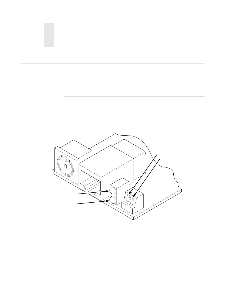
10/100Base-T
ADAPTER
STAT (System Status)
NET (Data to Network)
The Ethernet Interface at the rear of the printer for the 10/100BaseT interface has two indicator lights and two DIP switches, as shown
in Figure 2.
DIP Switches
1
2
Figure 2. Status Indicator Lights and DIP Switches
42
Run and Auto Reset Modes
Run mode is the normal operating state of the Ethernet Interface.
Auto Reset mode is entered when the watchdog timer is triggered
and the Print Server resets itself. In either mode, the STAT LED
flashes at a varying rate, depending on whether the unit IP address
is configured. The Run Mode and Auto Reset Mode indicator
descriptions are given in Table 1.
Page 43

10/100Base-T
Table 1. Run Mode and Auto Reset Mode Indicator Descriptions
STAT Indication Description
OFF flashes on once per second Normal Mode, IP address configured
OFF flashes on two times per
second
ON flashes off once per second Download (MOS)
ON flashes off twice per second Error
IP address not configured
Network Indicator
The NET LED displays the status of the network link. When the
NET LED is on, link integrity is confirmed. The NET LED flashes off
for 1/3 second when a data packet is being transferred. When the
NET LED is off, the network connection has been severed.
Table 2. NET LED Indicator
NET Indication Description
ON constantly Indicates link integrity
ON flashes off 1/3 second Flashes off 1/3 second each time a
packet is transmitted
43
Page 44

Chapter 1 Interfaces
ETHERNET
NET Indication Description
ON flashes Indicates activity
ON constant Indicates that the link is good at 10 Mbps
ON constant Indicates that the link is good at 100 Mbps
Integrated NIC Card LED:
Table 3. Integrated NIC LED Indicator
Wireless Network Indicator
WIRELESS
The wireless Ethernet Interface has 2 bi-color LEDs which can
produce three colors each: green, red, and yellow (green and red
combined). Table 4 shows the STAT LED states for various sytem
conditions:
Table 4. Wireless Ethernet Interface STAT LED States
System Condition STAT LED
44
System is running without an IP
address.
System is running with an IP address. Green, 1 Hz flash
System error. Red 2Hz flash
System is in upgrade mode with an IP
address.
System is in upgrade mode without an
IP address.
Green, 2 Hz flash
Yellow, 1 Hz flash
Yellow, 2 Hz flash
Page 45

10/100Base-T
Table 5 shows the NET LED states for various network conditions
when a WLAN card is inserted into the wireless Ethernet. The
Ethernet (wired) interface will not affect the NET LED while a
WLAN card is present.
Table 5. Wireless Ethernet Interface NET LED States
WLAN Network Condition NET LED
Network-link quality is good Green
Network-link quality is fair Yellow
Network-link quality is bad Red
Network-link not present Off
Network-link present and transmitting Link quality + blink
Table 6 shows the NET LED states for various network conditions
when no WLAN card is found or present.
Table 6. Wireless Ethernet Interface NET LED States
(No WLAN)
Wired Ethernet Network Condition
(No WLAN)
Network-link is present Green
Network-link is not present Off
Network-link present and transmitting Blink
NET LED
45
Page 46

Chapter 1 Interfaces
DIP Switches
ADAPTER,
WIRELESS
ADAPTER
DIP Switch
12
up up Normal operation. With both DIP switches in the “off” position, the
down up Factory default. With the DIP switches in this configuration, the
On the back of the printer, you will find a small window where you
can access two DIP switches labeled 1 and 2 (see Figure 2 on
page 42). The functions of the DIP switches are explained in
Table 7.
NOTE: The DIP switches are not marked with “on” or “off” labels.
Instead, the status of the switch is indicated by its position,
up or down. If the interface card has been installed upside
down (i.e., the DIP switches are to the left of the cable
connector), your DIP switch positions will be reversed and
the settings inverted.
Table 7. 10/100Base-T DIP Switch Settings
Comments
Ethernet Interface boots up using the settings in flash memory rather
than the default settings.
Ethernet Interface boots up and all settings stored in flash memory
are erased except the Ethernet address and key value.
up down Default IP. With the DIP switches in this configuration, the Ethernet
Interface boots up with factory default settings. However, the stored
settings in flash memory are intact. Setting DIP switch 2 to “on” does
not clear any settings stored in flash memory; it boots the unit in a
different state with the settings in flash memory temporarily ignored.
down down Reserved. This DIP switch configuration is not for customer use.
46
Page 47

Speed Setting for 10/100Base-T
Speed Setting for 10/100Base-T
When the router is set to auto-negotiation enable, the following is
the correct behavior of the Ethernet Interface with each setting:
1. 10mbps Half Duplex
Use parallel detection because the Ethernet Interface is using
force mode and thus has auto-negotiation disabled.
PORs to Half Duplex. Resets to Half Duplex. Reconnection at
switch maintains Half Duplex.
2. 10mbps Full Duplex
Use parallel detection because the Ethernet Interface is using
force mode and thus has auto-negotiation disabled.
PORs to Half Duplex. Resets to Half Duplex. Reconnection at
switch maintains Half Duplex.
3. 100mbps Half Duplex
Use parallel detection because the Ethernet Interface is using
force mode and thus has auto-negotiation disabled.
PORs to Half Duplex. Resets to Half Duplex. Reconnection at
switch results in Half Duplex.
4. 100mbps Full Duplex
Use parallel detection because the Ethernet Interface is using
force mode and thus has auto-negotiation disabled.
PORs to Half Duplex. Resets to Half Duplex. Reconnection at
switch results in Half Duplex.
5. Ethernet in Auto mode in 100mbps Full Duplex
environment
Use auto negotiation to the highest common local and remote
capability, i.e. 100 Full Duplex in this case.
PORs to 100/Full Duplex. Resets to 100/Full Duplex.
Reconnection at switch remains 100/Full Duplex.
47
Page 48

Chapter 1 Conventions Used In This Manual
6. Ethernet in Auto mode in 10mbps Half Duplex environment
(determined using 10hd hub)
Use auto-negotiation to the highest common local and remote
capability, i.e. 100 Half Duplex in this case.
PORs to 10 Half Duplex. Resets to 10 Half Duplex.
Reconnection at switch maintains 10 Half Duplex.
NOTE: With parallel detection, only speed can be determined. The
duplex mode sets to half duplex.
Conventions Used In This Manual
All uppercase print indicates control panel keys.
Example: Press the CLEAR key, then press the ONLINE key.
Quotation marks (“ ”) indicate messages on the Liquid Crystal
Display (LCD).
Example: Press the ONLINE key. “OFFLINE” appears on the LCD.
Command syntax and examples are formatted as follows:
48
• The Courier font in boldface indicates commands that you
type. For example:
At the prompt, type:
ping ftp.CompanyWebsite.com
• Regular Courier font indicates references to command syntax
and output. For example:
The ftp.CompanyWebsite.com site is working properly.
• Variable values are shown in brackets < > in command syntax,
output, and in text. For example:
ping <ipname>
The
<
ipname> is working properly.
Page 49

Notes And Notices
For your safety and to protect valuable equipment, read and comply
with the notes included in this manual. A description follows:
NOTE: A Note gives you helpful information and tips about printer
Speed Setting for 10/100Base-T
operation and maintenance.
Notes And Notices
49
Page 50

Chapter 1 Notes And Notices
50
Page 51

2 Installation And
Installation
Configuration
The Ethernet Interface provides an RJ-45 connector for
10/100Base-T (UTP) networks.
WIRELESS
ADAPTER
Connecting To The Network
To attach the Ethernet Interface to a network, plug the network
cable into the Ethernet Interface connector.
Watch the LEDs in the rear of the printer as they cycle through the
power-on self-test. When the test is complete, the STAT LED will
begin to flash.
51
Page 52

Chapter 2 Configuration Tools
A
Network Connector
Figure 3. Interior View of the Cabinet Model Showing Network Interface Location
A
and Setup
Configuration Tools
There are two parts to a Ethernet Interface setup:
• Configuring the Ethernet Interface so it can be seen on the
network. This involves network-related settings (e.g., an IP
address within TCP/IP environments) configured through the
built-in command shell, npsh, or from the control panel.
52
• Configuring a host with a new printer so it knows how to send
data to the Ethernet Interface. Just being able to see the printer
on the network does not mean you can automatically print to it.
A host has to be told where to send the data.
Page 53

Configuration Using The Control Panel
NOTE: Some network environments do not require any network
settings to be configured on the Ethernet Interface.
However, all network setups require configuration on the
host end.
Configuration Using The Control Panel
You can set Ethernet Interface settings from the printer control
panel.
CAUTION
When the printer is first powered on, the message “ETHERNET
INITIALIZING” displays on the control panel. To prevent a loss
of Ethernet Interface configuration information, do not change
the Ethernet Interface settings while this message is
displayed. When the initialization is complete, the message
“ETHERNET IS READY” displays, and you can safely change
the Ethernet Interface settings from the control panel.
1. You can set any of three listed parameters from the printer
control panel. These parameters are located in the Ethernet
Address, Adapter Address, or Wireless Address menu. Arrange
to have an IBM service technician install the Ethernet Interface
card if it is not already installed; this is not a customer
installable feature.
2. Power on the printer. The message “ETHERNET
INITIALIZING” appears when the printer is powered on.
Configuration can be done after the “ETHERNET IS READY”
message appears.
3. Disable the Power Saver mode before starting this procedure
to ensure that the configuration process runs uninterrupted.
See the
Infoprint 6500 User’s Guide
for instructions.
53
Page 54

Chapter 2 Configuration Tools
4. Always print an Ethernet Adapter test page before performing
any updates or network configuration using the following steps:
For 6500-v
a. Press STOP to take the printer offline. The printer is in the
NOT READY state.
b. Press RETURN + ENTER simultaneously to unlock the
printer menu.
c. Press MENU to display OPERATOR MENU.
d. Press ↑ Scroll/Micro until “OPERATOR PRINT TESTS”
displays, then press ENTER.
e. Press ↑ Scroll/Micro until the following displays:
“ETHERNET TEST PAGE” for the integrated or wireless
Ethernet.
“ADAPTER TEST PAGE” for the Ethernet Adapter.
f. Press ENTER.
5. Verify the current Ethernet Interface firmware version number.
NOTE: Firmware exists within the Ethernet Interface and the
printer itself. Each firmware is a separate entity with its own
version number. Please pay close attention to the type of
firmware referenced in the remaining sections of this
document.
printers:
54
The Ethernet Interface version should be 1.1.3 or higher for
10/100Base-T Ethernet adapters. If the Ethernet Interface
version is current, skip to step 6 below. If the Ethernet Interface
version is not current, you need to update both the Ethernet
Interface and printer firmware.
If you need to update the printer firmware, you must do so now.
After the update is complete, you must restart this instruction
from the beginning. To upgrade the printer firmware, contact
your IBM service representative.
Page 55

Configuration Using The Control Panel
CAUTION
Turning off the printer before the firmware update is complete
may permanently damage the Ethernet Interface adapter.
Updating the printer firmware takes time. Please be patient
and wait for the “ETHERNET IS READY” message to display
on the LCD. Do not turn off the printer before it has completed
the firmware download procedure. The LCD will display
“ONLINE / ETHERNET IS READY” when the download is
complete. Wait for this message before turning off the printer.
6. To enter IP Address parameters, do the following:
a. Press STOP to get to the NOT READY state.
b. Press RETURN + ENTER to unlock the printer menu.
c. Press Menu to display OPERATOR MENU.
d. Press ↑ Scroll/Micro until NETWORK SETUP displays,
then press Enter.
e. Press ↑ Scroll/Micro until ADAPTER ADDRESS or
ETHERNET ADDRESS displays, then press Enter.
f. Press ↑ Scroll/Micro until IP ADDRESS displays, then
press Enter.
g. Press Enter again, then ↑ Scroll/Micro to choose an IP
address octet to change. Press Enter.
h. Press ↑ Scroll/Micro to choose the desired value for the
octet, then press Enter. The new value is shown with an
asterisk. Press Return.
i. Repeat steps d and e until you have set all IP address
octets to the desired value.
j. Press Return until ADAPTER ADDRESS or ETHERNET
ADDRESS is on the first display line.
k. Press ↑ Scroll/Micro to choose other IP parameters to
change, then follow the above steps for each of these.
l. When finished, press Return multiple times until NOT
READY displays.
m. Press Start.
55
Page 56

Chapter 2 Configuration Tools
n. Wait for “ETHERNET IS READY” to display.
o. Press RETURN + ENTER to lock the printer menu.
7. Put the printer online and wait for the “ETHERNET IS READY”
message to display on the front panel. Placing the printer
online starts the Ethernet Interface IP Address and Netmask
update process. This process will take several minutes.
NOTE: If you do not put the printer online, the setting you just
entered will not take effect. Do not turn the printer off until
you see the “ETHERNET IS READY” message. If you turn
the printer off before the new values are written to memory
in the Ethernet Interface adapter, you will need to repower
the printer and repeat steps 6 and 7 above immediately.
8. Once the “ETHERNET IS READY” message displays, you may
enter the Gateway Address by repeating front panel steps 6
and 7 above. This will ensure the correct Netmask becomes
associated with the Gateway value you enter. From the front
panel navigate to the Gateway Address and enter the
appropriate value. You must press ENTER after inputting each
segment of the Gateway Address.
56
9. Put the printer online and wait for the “ETHERNET IS READY”
message to display on the front panel.
10. Enable the Power Saver mode if desired.
Page 57

Ethernet Interface Verification
Ethernet Interface Verification
Before performing the verification, you must connect the Ethernet
Interface card to the network.
1. Print an Ethernet test page (following the steps on page 53) to
verify the settings you made.
2. Verify the Netmask is correct in two locations on the Ethernet
test page:
• NETWORK INTERFACES
• TCP/IP ROUTING TABLE
The Netmask must be the same in both locations. For example,
if the Netmask is listed as 255.255.255.0 in NETWORK
INTERFACES and is listed as 255.255.255.255 in the TCP/IP
ROUTING TABLE, they do not match and you must correct it
for the Gateway. Also, if a Gateway Address was entered,
verify that “
Gateway Ping Test, where
Address. If a Gateway Address was not entered, the Default
Gateway Ping test is not required and will not display on the
page.
xxx.xxx.xxx.xxx
is alive” is printed under the Default
xxx.xxx.xxx.xxx
is the Gateway
If the Netmask does not match, complete the following steps:
a. Place the printer offline.
b. Using the front panel, modify the Gateway value to 0.0.0.0.
(non-configured).
c. Place the printer online and wait for the “ETHERNET IS
READY” message to display.
d. Place the printer offline and enter the Gateway Address
you desire.
e. Place the printer online and wait for the “ETHERNET IS
READY” message. This saves the new Gateway Address.
Your Ethernet Interface is now configured and connected to your
network.
57
Page 58

Chapter 2 Configuration Tools
Wireless Ethernet Interface Configuration Using The Control Panel
WIRELESS
ADAPTER,
WIRELESS
CAUTION
NOTE: The Access Point must be configured according to the
manufacturer's installation guide.
To configure Wireless Ethernet Interface, configure the ethernet
and wireless IP addresses so they can be seen on the network.
This includes several network-related settings (e.g., an IP address
within TCP/IP environments) configured through the built-in
command shell, npsh, or from the control panel.
IP Address Configuration
You can set the wireless Ethernet Interface IP settings from the
printer control panel.
When the printer is first powered on, the message
“ETHERNET INITIALIZING” displays on the control panel. To
prevent a loss of Ethernet Interface configuration information,
do not change the Ethernet Interface settings while this
message displays. When the initialization is complete,
“ETHERNET IS READY” displays, and you can safely change
the Ethernet Interface settings from the control panel.
You need to set both the ethernet and wireless network IP
addresses according to the TCP/IP environment that the printer is
connected to. There are four parameters accessed from the printer
control panel that are IP address related. These parameters are
located in the "ETHERNET ADDRESS" menu and the "WIRELESS
ADDRESS" menu:
58
• IP Address
This is the host for IP addresses that have four segments. They are
displayed as SEG1, SEG2, SEG3, and SEG4 which can be set to
any value in the range of 0 to 255.
Page 59

Wireless Ethernet Interface Configuration Using The Control Panel
• Subnet Mask
This is the subnet mask for the host IP that has four segments.
They are displayed as SEG1, SEG2, SEG3, and SEG4 which can
be set to any value in the range of of 0 to 255.
• Gateway Address
This is the gateway IP addresses that have four segments. They
are displayed as SEG1, SEG2, SEG3, and SEG4 which can be set
to any value in the range of 0 to 255.
• DHCP
The DHCP option allows you to obtain host server IP addresses
when powering onto the network. The DHCP can be configured to:
• Enable – each time you power on, the host server
automatically assigns you a different address (if the IP address
has not been previously assigned).
• Disable – You choose the host server IP address. After the
selection, the IP Address remains fixed even after you reboot.
Wireless Parameter Configuration
Certain "WIRELESS PARAMETERS" must be configured to match
the Access Point settings:
NOTE: The "ETHERNET PARAMETERS" are configured the
same way as the 10/100 Ethernet external Ethernet
Interface. Please refer to the Ethernet menu.
• Signal Strength
This menu displays the strength of the wireless signal.
NOTE: This is a display value only and cannot be changed.
• Operation Mode
This is the operation mode of the wireless network. The options
include “Infrastructure” or “Ad Hoc” mode.
59
Page 60

Chapter 2 Configuration Tools
• SSID Name
This is the Service Set Identifier which must be identical to the
Access Point's SSID name. The SSID name can be configured to a
maximum of 32 alphanumeric characters. The SSID name and
alphanumeric characters are divided into three parts in the control
panel menu as "SSID Name (01-15)", "SSID Name (16-30)" and
"SSID Name (31-32)".
NOTE: When two or more consecutive space characters are used
in the SSID, enclose it in a double quoted string;otherwise
upon resetting the Ethernet, the SSID Name wil be saved
in the Wireless Ethernet with only one space.
• Minimum Transfer Rate
Allows you to set the minimum speed at which the Wireless Option
will accept a connection (in million bits per second).
This is the wireless transfer rate, and can be set to either “enable”
or “disable.” It is set to “enable” when the operation mode is
"Infrastructure" so that the Ethernet Interface can automatically
detect the optimal transfer rate. If the operation mode is "Ad Hoc"
and the transfer rate is known, the user can enable or disable the
corresponding transfer rate in the menus "Xfer Rate 1Mb", "Xfer
Rate 2Mb", "Xfer Rate 5.5Mb" or "Xfer Rate 11Mb".
60
• Channel
This is the frequency used for wireless communication. The
2.4GHz band spectrum is divided into different channels (1-15). It is
set to "Default" so that the Ethernet Interface can detect the correct
channel to communicate with the Access Point in infrastructure
mode. If the operation mode is "Ad Hoc" and the channel is known,
the user can set the corresponding channel in this menu.
• Antenna Diversity
This is used to select the antenna for communication. It is
recommended to set to "Diverse" for the Ethernet Interface to
detect for optimal communication. It can also be set to "Primary" or
"Auxiliary".
Page 61

Wireless Ethernet Interface Configuration Using The Control Panel
• Preamble
This is the preamble used in the wireless packets. It is
recommended to set to "Default" so that the Ethernet Interface can
detect the correct preamble. The preamble is approximately 8 bytes
of the packet header generated by the AP and is attached to the
packet prior to transmission. The preamble length is transmission
data rate dependent. The "short" preamble is 50% shorter than the
"long" preamble. It must match the Access Point's preamble
configuration.
• Power Management
This option allows you to set power-save mode and sleep time. A
value specifying the sleep time in milliseconds will be provided. If
set to zero, power-save mode will be disabled.
• Transmit Power
This option allows you to specify the power level used by the
wireless card to send network packets to the access point. Transmit
power is specified as a percentage of full pwer (0 – 100%).
• International Mode
When enabled, the Wireless option adapts to international
frequency requirements in Europe.
• Authentication Method
This feature allows the user to select the authentication method
used for the wireless network interface. The options include open,
shared, kerberos, and leap.
• Default WEP Key
The default key must match the Access Point's configuration. If the
Access Point is configured to use "Open System", the default key
should be set to 0. If the Access Point is configured to use 40-bit or
128-bit WEP encryption key, the encryption key must be set to the
same setting as the Access Point's setting. See the following
section on how to set up the encryption key. In addition, there may
be four keys (1-4) that an Access Point can use. If the Access Point
is set to use key 1, the default key must be set to 1 to correspond to
the Access Point's setting.
61
Page 62

Chapter 2 Configuration Tools
Encryption Key Configuration
As mentioned above, there are four encryption keys that can be
configured through the control panel. For each encryption key x
(where x can be 1 to 4), the following control menu can be used to
configure the key:
• WEP Key x Format
This is the format of the key. It can be set to either ASCII or
Hexadecimal.
• WEP Key x Width
This is the number of bits used for encryption. This can be set to
either 40 Bits or 128 Bits and must match the Access Point's
configuration.
• WEP Key X
This is the key value. If the "KEY WIDTH" is set to 40 Bits, the key
values can be entered in the following 5 sub menus
(BYTE 1, …, BYTE 5). If the "KEY WIDTH" is set to 128 Bits, the
key values can be entered in the following 13 sub menus
(BYTE 1, …, BYTE 13). The key values must configure to match
the corresponding key in the Access Point's key configuration.
62
Authentication Method
This feature allows the user to select the authentication method
used for the wireless network interface. The options include open,
shared, kerberos, and leap.
Page 63

Wireless Ethernet Interface Configuration Using The Control Panel
Kerberos Parameters
NOTE: Kerberos parameters are available only with a Symbol
radio card.
Kerberos Enable
• Enable. Enable Kerberos authentication in the wireless
network interface.
• Disable (default). Disable Kerberos authentication in the
wireless network interface.
Kerb. Pwd (01–15)
First 15 characters of the Kerberos password (maximum number of
characters is 40).
Kerb. Pwd (16–30)
Characters 31 to 40 of the Kerberos password (maximum numer of
characters is 40).
Kerb. Pwd (31–40)
Characters 31 to 40 of the Kerberos password (maximum number
of characters is 40).
Reset Kerb. Pwd.
Reset Kerberos password to an empty string.
KDC Port Number
KDC (Key Distribution Center) port number is the 2-byte UDP/TCP
port used for Kerberos Communication.
• 88 (default)
• 0–65535
63
Page 64

Chapter 2 Configuration Tools
Clock Skew Units
• Seconds (default)
• Minutes
Clock Skew (SEC)
Sets the maximum allowable amount of time in seconds (SEC) or
minutes (MIN), as specified by the Clock Skew Units, that Kerberos
authentication will tolerate before assuming that a Kerberos
message is invalid.
• Seconds: The range is 60-900, and the default is 300.
• Minutes: The range is 1-15, and the default is 5.
NOTE: Whatever submenu is selected in Clock Skew Units will
display on the Clock Skew (SEC) menu. For example, if
you select Minutes, the Clock Skew (SEC) menu name will
change to Clock Skew (MIN).
Tckt Li f e U n i ts
64
Ticket lifetime unit in either seconds, minutes, hours, or days.
• Seconds (default)
• Minutes
• Hours
• Days
Page 65

Wireless Ethernet Interface Configuration Using The Control Panel
Tckt Life (SEC)
Sets the maximum allowable amount of time in seconds (SEC),
minutes (MIN), hours (HR), or days (DAY), as specified by the Tckt
Life Units, that a ticket obtained from the Kerberos server is valid
before getting a new one.
• Seconds: The range is 300-259200, and the default is 43200.
• Minutes: The range is 5-4320, and the default is 720.
• Hours: The range is 1-72, and the default is 12.
• Days: The range is 1-3, and the default is 1.
NOTE: Whatever submenu is selected in Tckt Life Units will
display on the Tckt Life (SEC) menu. For example, if you
select Hours, the Tckt Life (SEC) menu name will change
to Tckt Life (HR).
Renew Life Units
Renew lifetime unit in either seconds, minutes, hours, or days.
• Seconds (default)
• Minutes
• Hours
• Days
Renew Life (SEC)
Sets the maximum allowable amount of time in seconds (SEC),
minutes (MIN), hours (HR) or days (DAY), as specified by the
Renew Life Units, before warning for a new Kerberos password.
• Seconds: The range is 0-604800, and the default is 0.
• Minutes: The range is 0-10080, and the default is 0.
• Hours: The range is 0-168, and the default is 0.
• Days: The range is 0-7, and the default is 0.
The selected submenu is in Renew Life Units will display on the
Renew Life (SEC) menu. For example, if you select Days, the
Renew Life (SEC) menu name will change to Renew Life (DAY).
65
Page 66

Chapter 2 Configuration Tools
Equivalent Wireless Ethernet Interface
Configuration Using The Telnet Command
store ifc 2 wlan ssid <network-name>
store ifc 2 wlan mode adhoc|pseudo|managed
store ifc 2 wlan speed auto|(1 2 5 11)
store ifc 2 wlan channel default|(1-15)
store ifc 2 wlan antenna diverse|primary|aux
store ifc 2 wlan preamble default|long|short
store ifc 2 wlan pmm on|off
store ifc 2 wlan txpwr (0-100)
store ifc 2 wlan opts [[-]openauth][[-]intnl]
store ifc 2 wlan defkey disable|(1-4)
store ifc 2 wlan key <key-num> <key-sequence>
store ifc 2 wlan auth <auth-method> (e.g. openauth, shared, leap,
kerb)
66
store ifc 2 wlan user <auth-user-name>
store ifc 2 wlan pass <auth-password>
Refer to page 328 for the complete command set.
Wireless Cisco LEAP
LEAP is a Cisco wireless security scheme. The Cisco LEAP allows
for a WEP key timeout that forces re-authentication, resulting in the
derivation of a new WEP key for the session. To enable LEAP in
the NIC, enter the username and password corresponding to the
RADIUS server with the following commands:
store ifc 2 wlan auth leap
store ifc 2 wlan user <username>
store ifc 2 wlan pass <password>
NOTE: Disable the defkey to use LEAP.
Page 67

Kerberos Enabled Wireless NIC Configuration
WIRELESS
ADAPTER,
WIRELESS
Kerberos Enabled Wireless NIC Configuration
This section provides an example of how a user configures the
Print Server to use the Kerberos authentication via the wired Telnet
session.
This example assumes Symbol’s Access Point and RF card is used
and the Print Server has not been configured for Kerberos
authentication. It also assumes that the KDC, Access Point and the
Print Server are in the same realm.
To set up the Print Server for Kerberos authentication, the
administrator first has to enable Kerberos in the Access Point
according to Symbol’s instructions. Symbol’s Access Point must
have its Network time set up with the correct time server. Once the
Access Point is configured, the Print Server is ready to be
configured for Kerberos authentication.
Configuring the Print Server for Kerberos
Authentication
1. Create a user in the Windows 2000 server that identifies the
Print Server.
NOTE: The user name should be the Print Server’s name. The
password selected will be used as the Kerberos password
and should be set with no expiration.
2. In a secure networked environment, log in as a root user via
Telnet in the wired LAN.
3. Once logged in, use the Telnet commands to set up the
wireless LAN parameters (e.g. SSID = 103, operating mode =
Infra Structure mode, etc.) that match the Access Point
configuration.
In addition to the normal wireless LAN parameter settings, use
the following commands to enable Kerberos on the wireless
LAN interface and Kerberos for authentication (minimum
settings):
4. Set the wireless LAN interface parameters to enable Kerberos.
store kerberos opts auth
67
Page 68

Chapter 2 Configuration Tools
5. Set the Kerberos parameters to enable Kerberos
authentication.
The Kerberos password must match the Windows 2000 user
password for the Print Server. The administrator should choose
at least 9 alphanumeric characters with a combination of upper
and lower case.
The following is a suggestion for creating strong password for
computer security. Make sure the password:
• is at least seven characters long. The most secure
passwords are seven to 14 characters long.
• contains characters from each of the following groups:
letters (uppercase and lowercase), numerals, and symbols (all
characters not defined as letters or numerals, i.e., ! @ # $ % ^
& *, etc.)
The kname is default to “krbtgt” which is the default name used in
Windows 2000 KDC. It must be configured to match with the KDC if
the default is changed. The krealm is case sensitive; it must match
the Access Point’s realm.
68
The SSID of the Print Server must be configured to match the
Access Point’s SSID which also has Kerberos enabled. For
example, if a Windows 2000 user created the password
aBcd-12345 and the Access Point’s realm is set to
REALM.PRINTRONIX.COM, the following telnet commands are
used:
store kerberos password aBcd-12345
store kerberos config krealm REALM.IBM.COM
NOTE: If the Kerberos authentication fails, the user will not be able
to Telnet to the Print Server via the wireless LAN interface.
In this case, Telnet to the Print Server via the wired LAN
interface. It should display an error message indicating the
reason for the Kerberos authenticaion failure.
Page 69

HTML Forms
HTML Forms
The Ethernet Interface settings can be configured over TCP/IP
through a standard Web browser. The Ethernet Interface Web
pages provide a handy way to access some of the commands built
into the print server.
NOTE: If a router is used, make sure a Gateway value is
configured.
To access the Ethernet Interface home page:
1. Make sure the print server has an IP address and Subnet Mask
so it is recognizable on your TCP/IP network.
2. Make sure your network station can successfully ping the
Ethernet Interface over the network.
3. Direct your Web browser to the URL:
http://IPaddress
(e.g., http://192.75.11.9)
where IPaddress is the IP address of your Ethernet Interface.
The Ethernet Interface HTML structure is divided into several
menus as shown in Figure 4.
69
Page 70

Chapter 2 Configuration Tools
Index/Home
Configuration
TCP/IP
802.11b
Windows
Novell
Alert Config 1
Alert Config 2
Alert Config 3
Alert Config 4
Alert Config 5
Alert Config 6
Alert Config 7
Alert Config 8
Alert Config 9
Alert Config 10
Status
I/O Port
Network
d1prn
d2prn
d3prn
d4prn
d5prn
d6prn
d7prn
d8prn
Help
Print ModelPrint PathNetwork
m1
m2
m3
m4
m5
m6
m7
m8
AdministrationSNMP
About
Log Path
l1
l2
l3
l4
l5
l6
l7
l8
System
IBM Printing
Systems
TN5250/
TN3270
d1prn
d2prn
d3prn
d4prn
d5prn
d6prn
d7prn
d8prn
70
Figure 4. Ethernet Interface HTML Structure
NOTE: Online help is available for all HTML pages.
Page 71

HTML Forms
Printer Status Screen
Using the printer IP Address and any standard Web browser, you
can check the status of the printer. Figure 5 shows the exact state
of the printer by showing the printer LCD message. (This screen
automatically refreshes every minute.)
Figure 5. Printer Status Screen
71
Page 72

Chapter 2 Configuration Tools
Configuration Alternatives
Besides the HTML forms and software provided, the Ethernet
Interface internal command shell, npsh, can also be reached using
Telnet and Remote Shell, and FTP.
Telnet
A TCP/IP command that helps configure Ethernet Interface settings
remotely. A TCP/IP host starts a Telnet session with the print
server and logs into the device command shell to alter and view
settings.
Example:
telnet 192.75.11.9
Remote Shell
A TCP/IP command that helps configure print server settings
remotely. A TCP/IP host uses this command to remotely execute a
single command on the Ethernet Interface.
72
Example:
rsh spike list prn
This command remotely executes the npsh command list prn
on the Ethernet Interface named
spike
.
FTP
FTP can also be used to configure print server settings remotely. A
TCP/IP host uses FTP to store a file containing 1 or more NPSH
commands on the FTP file system. The configuration file must be
FTP ‘put’ to the /config/default/defaultCfg file. The configuration file
can later be executed on demand using the ‘load oem’ command
during a telnet (NPSH) session. The configuration file is also
executed automatically during the power-up sequence when DIP
switch 1 is closed.
Page 73

3 Embedded Ethernet
Overview
Interface Web Page
The Ethernet Interface comes with an extremely powerful printer
management tool that allows you to monitor, configure, and
manage both the printer and its print job. The Ethernet Interface
comes with an embedded web server that allows System
Administrators and users access to its printer management
capabilities from a standard web browser.
The Ethernet Interface printer’s IP address is used as a URL,
similar to the URL of an Internet web page. When a web browser is
activated and the printer’s IP address is entered, the printer’s
embedded web server will display its home page, with links to the
printer’s status and configuration settings.
All of the Ethernet Interface’s configuration settings are protected
by a password so unauthorized users cannot make changes. When
you try to open any of the Ethernet Interface’s configuration pages,
you are asked for your user name and password. At the prompt,
you need to enter
with root privileges) followed by the associated password. If there is
no password, just press
passwords, refer to “Ethernet Interface Security” on page 365.
root (unless you have another user configured
ENTER. For more information on setting
73
Page 74

Chapter 3 Configuration
After you configure the Ethernet Interface settings, and click the
SUBMIT button on the related form, reset the Ethernet Interface to
ensure the latest settings are in use. To reset the Ethernet
Interface, go to the System form under the Configuration Menu and
click the REBOOT button.
The embedded Ethernet Interface Web server gives you the ability
to configure the network adapter, monitor printer status, and to
manage print jobs. The Ethernet Interface Web page structure is
divided into several menus, as shown in Figure 4.
Configuration
The Configuration menu items allow you to configure the settings
for the following items:
• Network - this menu item allows you to change the network
setting for each protocol: TCP/IP, 802.11b, NetBIOS over
TCP/IP, and Netware.
• Print Path - this menu item allows you to change the name of
the destination queues, and define how the print job will be
preprocessed before printing. It allows you to select what
information to log.
74
• Print Model - this menu item displays model settings one at a
time.
• Log Path - this menu item displays log path settings one at a
time.
• TN5250/3270 - this menu item allows you to configure the
TN5250/3270 settings.
Page 75

Configuration
• SNMP - this menu item allows you to configure the SNMP trap
manager settings. It also allows you to define the printer event
types to monitor, and the e-mail address that should receive
alert notifications.
• Administration - this menu item allows you to define or change
the printer name, location, description, etc. It also allows you to
change the root and guest user passwords and SMTP server.
• System - this menu item allows you to reboot the Ethernet
Interface, or restore its settings to the factory default.
75
Page 76

Chapter 3 Network Configuration
Network Configuration
The network configuration allows you to specify the setting for each
network protocol. Beside each protocol name is a checkbox which
allows you to enable or disable each protocol depending on your
network printing needs.
NOTE: TCP/IP is the only supported protocol which is always
enabled.
TCP/IP Network
76
Figure 6. TCP/IP Network Configuration
Page 77

TCP/IP Network
Interface
The two edit fields contain the Ethernet Interface's IP address and
subnet mask. The check boxes enable the RARP, BOOTP, DHCP,
DNS, and Persist DHCP protocols, which are alternate methods of
assigning IP addresses. On most networks, you want to enter a
permanent IP address and subnet mask and disable RARP,
BOOTP, DHCP, DNS, and Persist DHCP. However, if your network
requires one of these, you should clear the IP address (and
possibly the subnet mask) fields and ensure that the appropriate
check box is selected.
Routing
The routing table tells the Ethernet Interface which router or
gateway to use to access other subnets or hosts. In most
situations, you can simply add your router's IP address as the
default router. All packets destined for other subnets will be
forwarded to the default router for delivery to the destination host. If
you have more complex routing requirements, add static routing
entries for specific hosts or networks in the remaining Routing rows.
Packets with IP addresses that match a given Destination and
Mask (from the first two fields in a Routing row) will be routed to the
router/gateway named in the third field. Packets which do not
match any of the listed Destinations and Masks will be routed to the
default router if one is set.
77
Page 78

Chapter 3 Network Configuration
802.11b
78
Network Name
Enter the wireless network name. Maximum length of 32
characters.
NOTE: When you use telnet, Network Name is called SSID.
Mode
Set the mode of operation for the wireless device. Pseudo, Adhoc,
and Managed are the available settings.
NOTE: When you use telnet, the “managed” setting is called
“infrastructure.”
Page 79

802.11b
Speed
Change the selected bit-rates. Choosing "auto" will select auto
settings even if some or all of the checkboxes are selected. To
manually choose bit-rates, change speed option to "user" and
check the appropriate checkboxes. If "user" is selected, and no
checkboxes are checked, then the automatic setting is used.
Channel
Set the RF Channel for the wireless device. Selecting "Default" will
ignore user entered value in field, and set the RF Channel to the
default setting.
Antenna
Choose the antenna type. Diverse, Primary, and Aux are the
available settings.
Preamble
Change the preamble length. Default, Short, and Long are the
available settings.
Power Management Mode
Change the power management mode and adjust the power-save
sleep time (milliseconds). Selecting "Off" will turn the Power
Management Mode off and set the power-save sleep time to zero.
Transmit Power
Adjust RF transmit power in percent of full power.
Options
Set the International Mode option
Key
Change the key used for WEP encryption. Ascii-Hex Format.
Ex: 0123456789abcdef0123456789
79
Page 80

Chapter 3 Network Configuration
Default Key
Change the default key number used for WEP encryption.
Authentication Method
Select the desired authentication method to be used when
communicating with an access point.
User
Enter a user name to be used when authenticating with an access
point. Currently only used for LEAP authentication.
Password
Enter the password to be used when authenticating with an access
point. Currently only used for LEAP authentication.
80
Page 81
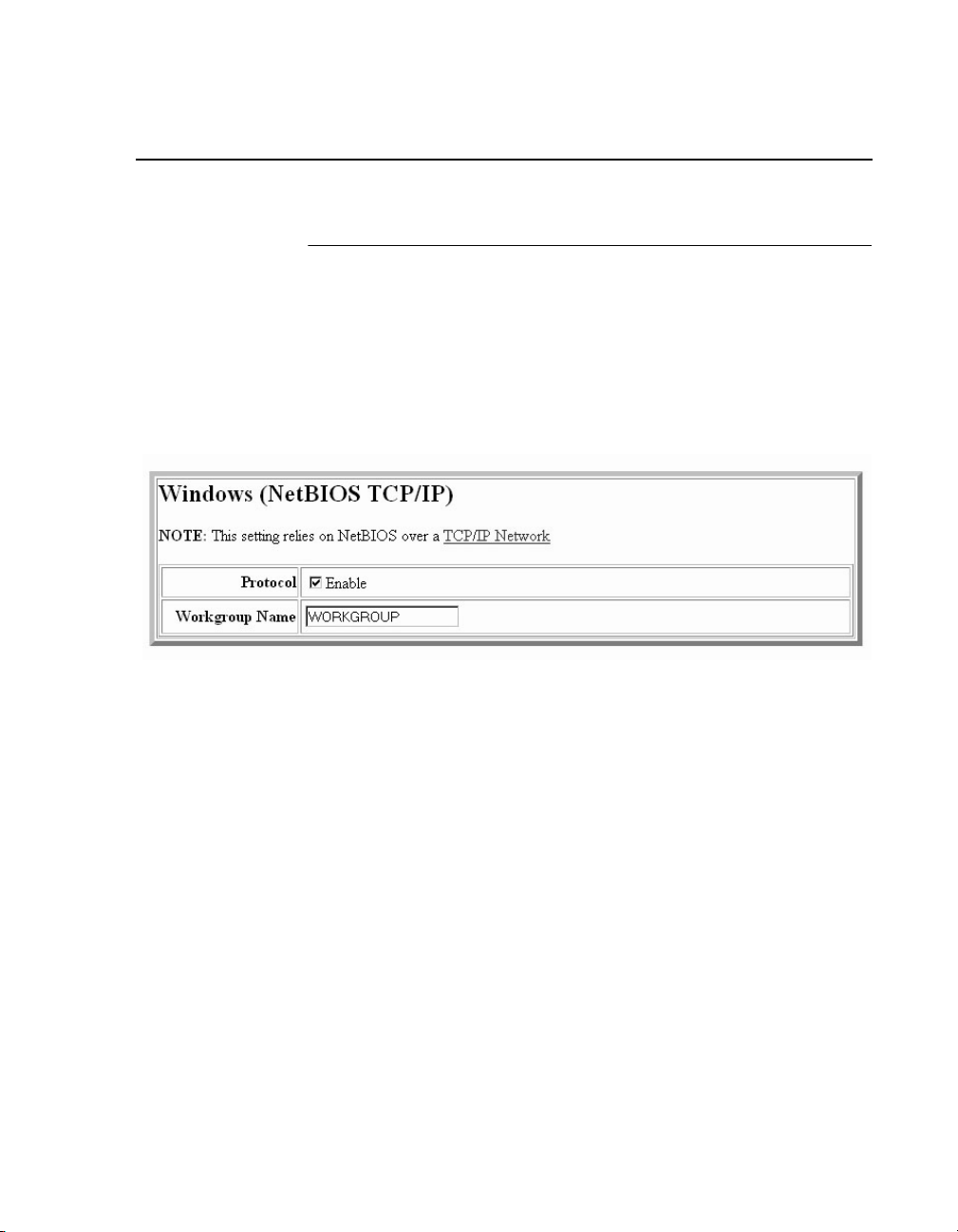
Windows Network (NetBIOS TCP/IP)
Windows Network (NetBIOS TCP/IP)
TCP/IP is used for Windows (i.e. Netbios, Windows 95/98/Me, and
Windows for Workgroups) printing unless another protocol like IPX
is available. Therefore, mandatory TCP/IP settings (i.e. IP address
and subnet mask) are necessary on the Ethernet Interface. Go to
“TCP/IP Network” on this form to fill in these settings if you haven't
done so already.
Figure 7. Windows Network (NetBIOS TCP/IP) Configuration
Workgroup Name
This name specifies which Windows workgroup the Ethernet
Interface will reside in.
81
Page 82

Chapter 3 Network Configuration
Novell Network
ADAPTER,
WIRELESS
ADAPTER
Novell configuration is supported only on the Ethernet Adapter and
Wireless Adapter.
Figure 8. Novell Network Configuration
82
FrameType
This option determines which framing scheme will be used in
processing Novell signals. The different types of Ethernet packet
formats include:
• Auto Sensing (the default)
• Ethernet II
• Ethernet 802.3
• Ethernet 802.2
• 802.2 Snap
Page 83

Novell Network
Service Type
Allows you to change the Nest Server. The options are:
• Bindery
• NDS
• Auto
File Server
Define a Novell file server for the Ethernet Interface to service as
either a PSERVER or an RPRINTER.
NDS
NDS (Novell Directory Services) is a distributed database of
network information. An NDS contains information that defines
every object on the network. For more information please see your
Novell administrator.
Pserver
Define a password for the Ethernet Interface to use when logging in
to the file server as a PSERVER. This is an optional file server
security feature.
Rprinter
Define an RPRINTER setup so the Ethernet Interface knows to
service a PSERVER.NLM on a Novell file server. Define the
PSERVER.NLM name, the number of the printer serviced by the
Ethernet Interface within this PSERVER.NLM, and the destination
on the Ethernet Interface you want the print jobs to pass through.
83
Page 84

Chapter 3 Print Path Configuration
Print Path Configuration
The Ethernet Interface print path is the path a print job takes when
it reaches the network adapter. First the job goes to a destination/
queue (e.g. d1prn) where it then passes through an associated
model (e.g. m1) for extra processing and logpath (e.g., l1) for job
and printer logging. Finally the job reaches the Ethernet Interface's
I/O port (e.g. PRN) where it passes through to the attached printer.
The “Print Path” form displays one destination's settings at a time.
From here, you can then select another destination or you can go
directly to an I/O port to configure port settings.
Destination Settings
84
Figure 9. Print Path Configuration, Destination Settings
Name
Name of the destination. The default destination queue names are
d1prn, d2prn, d3prn, and d4prn, d5prn, d6prn, d7prn, and d8prn.
Back Channel
I/O port to receive printer feedback when a print job passes through
this destination. By default all print queues have no backchannel.
Page 85

Destination Settings
Services
Define what type(s) of print services the destination will support. By
default all services are enabled.
Parameters
socket Printing to a TCP port number (e.g. 9100) on the
Ethernet Interface
lpd Remote printing using the Line Printer Daemon
lpsched System V printing using the “lp” command
ADAPTER,
WIRELESS
ADAPTER
ADAPTER,
WIRELESS
ADAPTER
rprinter Novell's remote printer setup
pserver Novell's PSERVER setup
netbios Printing from Windows stations relying on
NetBIOS over TCP/IP
ftpd Printing using the File Transfer Protocol (FTP)
tn5250/3270 Printing using tn5250/3270 configuration
Selected Model
Defines the model configuration that is to be associated with the
current destination. The default model names are m1, m2, m3, m4,
m5, m6, m7, and m8.
85
Page 86

Chapter 3 Print Path Configuration
Current Model Settings
Figure 10. Print Path Configuration, Current Model Settings
Model Type
The option is available on the Print Model web page. For a
description, see page 88.
86
Banner Page
The option is available on the Print Model web page. For a
description, see page 89.
Filter
The option is available on the Print Model web page. For a
description, see page 89.
Header String
The option is available on the Print Model web page. For a
description, see page 89.
Trailer String
The option is available on the on the Print Model web page. For a
description, see page 90.
Page 87

Current Log Path Settings
Printer Configuration
The option is available on the Print Model web page. For a
description, see page 90.
Selected Log Path
This option defines the log path configuration that is to be
associated with the current destination.
Current Log Path Settings
Figure 11. Print Path Configuration, Current Log Path Settings
Log Path Type
The option is available on the Log Path web page. For a
description, see page 91.
Log Path Port
The option is available on the Log Path web page. For a
description, see page 92.
87
Page 88

Chapter 3 Print Model Configuration
Print Model Configuration
88
Figure 12. Print Model Configuration
Name
Name of the model. The default model names are m1, m2, m3, m4,
m5, m6, m7, and m8.
Model Type
Define what processing (if any) will be performed on print jobs
passing through the associated destination. If set to “raw”, the job
will not be modified by the network adapter.
Page 89

Print Model Configuration
Current Log Path Settings
Banner Page
Tells the Ethernet Interface to produce a banner page with each
print job. The type of banner page data can be text. You can also
specify whether the banner page should come at the front or the
end of a print job.
Filter
Specify whether the Ethernet Interface is to add carriage returns to
print jobs passing through that contain solitary linefeeds. This is
common with Unix text jobs resulting in stair-stepped output.
Header String
Define an escape sequence to be sent to the printer before each
print job. For example, you may want to send a sequence to print
the job in landscape mode or to a certain tray on the printer. You
can specify up to four separate sequences per header string. The
Ethernet Interface will execute them in order from top to bottom. If
specifying fewer than four sequences, be sure to start at the top
leaving undefined fields at the bottom.
The most common sequences are listed on the form:
• Print landscape - tells the printer to print in landscape mode.
• Print portrait - tells the printer to print in portrait mode.
89
Page 90

Chapter 3 Print Model Configuration
Trailer String
Define an escape sequence to be sent to the printer after each print
job. For example, you may want to send a sequence to add a
formfeed so you don't have to manually press the formfeed button
on the printer. You may also want to tell the printer to reset itself in
case you have set a header string which tells the printer to do
something special with the job. You can specify up to three
separate sequences per trailer string. The Ethernet Interface
executes them in order from top to bottom. If specifying fewer than
three sequences, be sure to start at the top leaving undefined fields
at the bottom.
The most common sequences are listed on the form:
• PCL Reset - tells the printer to reset itself once the data
completes
• End of Transmission (EOT) - tells the printer to force the end of
the job
• Formfeed - tells the printer to do a formfeed at the end of the
data.
90
Printer Configuration
Specify a printer configuration number to be loaded before
processing the print job. This ability to associate a printer
configuration to a logical printer model allows you to define up to
eight unique and independent printer personalities in a single
printer. Using this feature, you effectively have eight different
printers in one.
To associate a printer configuration to the currently selected
destination queue, just select the desired printer configuration
number from the drop down list. Once a printer configuration has
been associated with a destination queue, any print job sent to that
destination queue name will cause the printer to load the
associated printer configuration before processing the print job.
Page 91
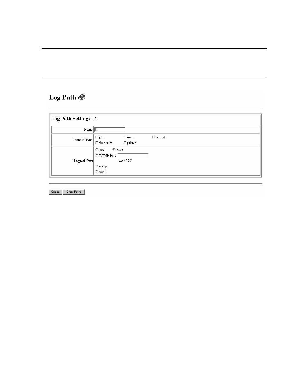
Log Path Configuration
Figure 13. Log Path Configuration
Log Path Configuration
Current Log Path Settings
Name
Name of the log path. The default names are l1, l2, l3, l4, l5, l6, l7,
and l8.
Logpath Type
Define what type of log information will be tracked for each print job
passing through the associated destination. The types are:
• job - job ID, username, etc.
• user - user ID and three messages per job about the start and
finish
• checksum - value used when troubleshooting integrity of data
transferred
• printer - miscellaneous messages from the printer
• i/o port - status of the printer based on the port interface
signals.
91
Page 92

Chapter 3 Log Path Configuration
Logpath Port
Define where logging information for print jobs passing through the
associated destination will be reported. The choices are:
• prn - reported to the PRN port
• none - don't report any logging information
• TCP/IP port - to a TCP port number (specified in the edit field)
• syslog - to a host (specified by the IP address in the edit field)
running a SYSLOG daemon
• email - to an e-mail address (specified by the e-mail address
and the SMTP server IP address edit fields). You can set the
option on the Administration web page.
NOTE: The values defined in Logpath Type and Logpath Port are
common among all destination queue.
Default:
no logging turned on.
92
Page 93

TN5250/3270 Configuration
The TN5250/3270 configuration form allows you to specify settings
for up to eight different TN5250/3270 sessions.
NOTE: The standard Ethernet module does not support TN5250/
3270 protocol. However, the TN5250/3270 software is
available as an option you can order or as factory installed.
TN5250/3270 Configuration
Current Log Path Settings
Figure 14. TN5250/3270 Configuration, TN5250 Mode
93
Page 94

Chapter 3 TN5250/3270 Configuration
94
Figure 15. TN5250/3270 Configuration, TN3270 Mode
Mode
Specifies the TN protocol mode for the current configuration.
Default:
TN5250
Host IP
Specifies the IP address or domain name of the host (iSeries for
TN5250) for the current configuration.
Default:
Unconfigured (empty) host.
Page 95

TN5250/3270 Configuration
Current Log Path Settings
Port
Specifies the UDP port number of the TN5250 or TN3270 server for
the current configuration.
Default:
23
Resource Name
(TN3270 mode) Specifies the name of the iSeries LU session for
the current configuration. The resource name entered will be the
name of the printer device created on the iSeries host for the
current session. The name is limited to 10 characters in length,
must start with an alpha character (a-z, A-Z), and contain only
alphanumeric characters and underscores.
Default:
Unconfigured (empty) resource name
Device Description
(TN5250 mode) Specifies the name of the printer device for the
current configuration. The description entered will be the name of
the printer device created on the iSeries host for the current
session. The name is limited to 10 characters in length, must start
with an alpha character (a-z, A-Z), and contain only alphanumeric
characters and underscores.
Default:
Unconfigured (empty) description
Message Queue Name
(TN5250 mode) Specifies the queue name to which system
messages will be logged.
Default:
QSYSOPR
Message Queue Library
(TN5250 mode) Specifies the queue library to which system
messages will be logged.
Default: *LIBL
95
Page 96

Chapter 3 TN5250/3270 Configuration
Device Type
By default, the device type is always set to IBM.
WSCST Name
(TN5250 mode) As declared on the iSeries host for the created
printer device.
Default: Unconfigured (empty) name
WSCST Library
(TN5250 mode) As declared on the iSeries host for the created
printer device.
Auto Connect
Specifies whether the Ethernet will automatically connect to the
iSeries host.
Default: Disabled
96
Start/Stop Auto Connect
Specifies whether the Ethernet should retry automatic connection
to the iSeries host.
Default: 'Start' if Auto Connect is currently stopped, 'Stop' if Auto
Connect is currently started.
Page 97

SNMP Configuration
The SNMP Configuration form allows you to configure SNMP trap
managers and the e-mail alert features of the Ethernet Interface. It
allows you to configure how SNMP alerts are processed by a
SNMP trap manager, an Unix syslog logging daemon, and/or have
e-mail notifications sent. Up to 10 SNMP trap managers and e-mail
recipients may be specified. Individual alerts fall into one of 12 alert
group categories, providing the ability to filter alert notices as
desired.
SNMP Manager Alert Posting Settings
SNMP Configuration
Current Log Path Settings
Figure 16. SNMP Manager Alert Posting Configuration
Specifies whether alerts from the enabled alert group categories for
this configuration will be sent to the SNMP manager. If this option is
enabled, the following information must be entered:
• SNMP Manager IP Address - specifies the IP address of the
SNMP trap manager
• UDP Port - specifies the UDP port number used by the SNMP
trap manager for receiving trap messages. Acceptable values
are 162, and 49152 through 65535
• Community Name - up to 15 character string specifying the trap
community name.
97
Page 98

Chapter 3 SNMP Configuration
Syslog Alert Posting Settings
Figure 17. SNMP Syslog Alert Posting Configuration
Specifies whether alerts from the enabled alert group categories for
this configuration will be sent to the Unix syslog daemon. If this
option is enabled, the syslog daemon IP address must be entered
in the syslog field in the System Information section of the
Administration Configuration form.
Email Alert Posting Settings
98
Figure 18. SNMP Email Alert Posting Configuration
Specifies whether alerts from the enabled alert group categories for
this configuration will be sent to the specified e-mail address. If this
option is enabled, the following information must be entered:
Page 99

SNMP Configuration
Current Log Path Settings
Email Address
Specifies an e-mail address to which alert information will be sent.
Short E-mail Format
Specifies whether a short (15-80 character) alert e-mail message
should be sent.
If enabled, the message will contain the alert description, the
severity level, the device description, and device name (unless the
length of the message exceeds the Short E-mail Message Length,
in which case the message will be truncated).
If disabled, the message will contain additional information
including the device description, device name and location, alert
description, alert group, alert severity level, and printer status.
Default:
Disabled
Short E-mail Message Length
Specifies the maximum size of the short e-mail message.
Acceptable values are 15 to 80 characters.
Default:
80 characters
Send Test Message
provides a way to test the validity of the e-mail address/SMTP
server address. If checked, a test message will be sent to the
specified e-mail address when the submit button is pressed.
Default:
If the alert message is to be sent to a cellular phone or pager, the
Short Email Format option should be enabled. Once this option is
enabled, you may specify the maximum e-mail message length
(15-80 characters). When enabled, the message will contain the
alert description, the severity level, device description, and device
name (unless the length of the message exceeds the Short Email
Message Length, in which case the message will be truncated).
All alert groups are disabled by default.
99
Page 100

Chapter 3 SNMP Configuration
If the Short Email format is disabled, the message will contain
additional information including the device description, device
name and location, alert description, alert group, alert severity
level, and printer status.
To test the validity of the e-mail address and the SMTP server
address, enable the Send Test Message option. If the Send Test
Message box is checked, a test message will be sent to the
specified email address when the submit button is pressed.
Alert Groups
100
Figure 19. SNMP Alert Groups Configuration
Specifies which alert groups are enabled for reporting for this
configuration. When an alert occurs that is contained in one of the
enabled alert groups, it will be posted to the specified SNMP
manager, Unix syslog daemon, and/or e-mail address. The
following table describes which printer events belongs to which
Alert Group.
 Loading...