

IBM InfoPrint 6400 Series, InfoPrint 6500 Series, InfoPrint 6700 Series, InfoPrint 4400 Series Printer Management Utility User’s Manual
Page 1

InfoPrint 6400/6500
Series Line Matrix Printer
InfoPrint 6700/6700-M40/4400
Series Thermal Printer
G550-0972-01
Printer Management Utility User’s Manual
Page 2

Page 3

InfoPrint 6400/6500
Series Line Matrix Printer
InfoPrint 6700/6700-M40/4400
Series Thermal Printer
G550-0972-01
Printer Management Utility User’s Manual
Page 4

Second Edition (September 2008)
This edition applies to the InfoPrint 6400/6500 Series Line Matrix Printers, 6700/4400 Series
Thermal Printers, and 6700-M40 Series Thermal Printers and replaces the following publication:
Printer Management Utility User’s Manual,
G550-0972-00.
You can send comments by e-mail to printpub@us.ibm.com or by mail to:
InfoPrint Solutions Company, LLC
6300 Diagonal Hwy 002J
Boulder, CO 80301-9270
U.S.A.
This product is or contains commercial computer software and commercial computer software
documentation developed exclusively at private expense. As specified in Federal Acquisition
Regulation 12.212 in the case of civilian agencies and Defense Federal Acquisition Regulation
Supplement 227.7202 in the case of military agencies, use, duplication and disclosure by agencies
of the U.S. Government shall solely be in accordance with the accompanying International
Program License Agreement in case of software products and in accordance with the licensing
terms specified in the product’s documentation in the case of hardware products.
© Copyright InfoPrint Solutions Company 2008. All rights reserved.
Before using this information and the product it supports, read the information in “Notices” on
page 201.
Note!
Visit our home page at: http://www.infoprint.com
Internet
Page 5

1 Overview ................................................................ 9
The Printer Management Utility...............................................................9
Requirements .......................................................................................... 9
Installing the Software .............................................................................9
Printer Setup ......................................................................................... 10
PMU Method .................................................................................... 10
Telnet Method .................................................................................. 10
Operator Panel Method .................................................................... 11
Set Password ................................................................................... 13
Set Telemetry Path (6700/4400 Series Only)................................... 14
Check Port Number..........................................................................14
Loading and Using Foreign Language Fonts ........................................ 15
Limitations ........................................................................................ 15
Windows Setup ................................................................................ 15
Unix Setup........................................................................................16
Getting Started ...................................................................................... 17
2 Printer Database.................................................. 23
Overview ............................................................................................... 23
The Menu Bar........................................................................................25
The File Menu .................................................................................. 25
Preferences ......................................................................................26
The Edit Menu ..................................................................................32
The View Menu ................................................................................ 33
The Applications Menu.....................................................................37
The Status Menu ..............................................................................38
The Utilities Menu ............................................................................ 51
The Help Menu.................................................................................52
The Toolbar ........................................................................................... 53
Managing the Database ........................................................................ 55
Database Items ................................................................................ 55
Defining Printer Properties ...............................................................56
Table of Contents
Page 6

Table of Contents
3 Applications and Web Access..............................67
Configuration Editor............................................................................... 67
Menu Tree........................................................................................ 68
Creating Configurations ................................................................... 68
Changing Configurations..................................................................69
Saving Configuration Files ............................................................... 72
Opening Configuration Files.............................................................72
Downloading Configurations ............................................................ 73
Uploading Configurations.................................................................73
Migration .......................................................................................... 73
Factory Settings Differences ................................................................. 77
Menu Bar..........................................................................................78
Toolbar ............................................................................................. 79
Configuration Settings Differences Views ........................................ 80
Displayed Language ........................................................................81
Flash File Manager................................................................................82
Get File Info......................................................................................83
Upload.............................................................................................. 84
Delete And Optimize ........................................................................ 85
CST Manager ........................................................................................ 85
File Download........................................................................................86
Define The Download Files .............................................................. 87
Download The Files ......................................................................... 88
Recovery File ................................................................................... 99
Media Profiler ......................................................................................100
The Menu And Toolbar ..................................................................101
Profiler View ...................................................................................103
The Status Bar ............................................................................... 107
For More Information......................................................................107
Operator Panel .................................................................................... 108
Primary/Secondary Operator Keys ................................................ 111
Message Display ............................................................................ 111
Status Indicator .............................................................................. 111
Disabled Indicator .......................................................................... 111
In Progress Indicator ...................................................................... 111
Information Capture.............................................................................112
File ................................................................................................. 113
Configuration Printout .................................................................... 113
Error Log ........................................................................................ 113
Directory......................................................................................... 114
ODV Quality Wizard ............................................................................ 115
Speed Keys ......................................................................................... 116
Page 7

Table of Contents
Job Capture .........................................................................................117
Job Capture Features .................................................................... 118
Web Access ........................................................................................ 121
The PMU Web Site URL Address .................................................. 121
Login To The PMU Web Site.......................................................... 122
Changing The User Password ....................................................... 122
The Printer List Page ..................................................................... 123
Changing User Settings, IP Addresses, and IP Address
Ranges ...........................................................................................124
4 Utilities ............................................................... 127
Reboot Printer ..................................................................................... 127
Set Printer Password...........................................................................127
Set Wireless Properties .......................................................................129
General Tab ................................................................................... 129
WEP Encryption Tab ......................................................................131
Kerberos Tab ................................................................................. 132
EAP Tab......................................................................................... 136
WPA Tab........................................................................................ 137
Macro Utility......................................................................................... 138
Configure Macro.............................................................................139
SNMP Browser ....................................................................................141
Assign IP Address ...............................................................................142
Enable Remote Printer Management ..................................................143
Lock/Unlock Menus ............................................................................. 144
Configure Print Servers .......................................................................145
5 Datastream Adapter ........................................... 147
Overview ............................................................................................. 147
CST Manager ...................................................................................... 148
The Menu And Toolbar ..................................................................149
Input/Output Fields .........................................................................153
The CST Listing Field.....................................................................154
CSTs and CST Bundles ................................................................. 154
Status Bar ...................................................................................... 154
Modes And Attributes ..........................................................................155
Modes ............................................................................................ 155
Attributes ........................................................................................158
Additional Features ............................................................................. 160
The Use Once Flag ........................................................................160
The Entry On/Off Flag ....................................................................161
Edit Information ...................................................................................161
General Tab ................................................................................... 161
Memo Tab ...................................................................................... 161
Page 8

Table of Contents
Patterns / Variables ............................................................................. 162
Pattern Character Tab.................................................................... 162
Pattern Tab ....................................................................................164
Formatted Pattern Tab ................................................................... 166
How to Use Patterns ...................................................................... 169
Pattern Recognition Example......................................................... 170
Variable Tab ................................................................................... 178
Status Response Definition ................................................................. 179
Conditions ...................................................................................... 180
Protocols ........................................................................................ 180
How To Use Conditions And Protocols .......................................... 181
Status Response Generator Example............................................182
CST Manager And EBCDIC ................................................................ 186
CST Manager Version Control System ............................................... 195
Application Name and Version Information .................................... 195
Viewing File Version Information.................................................... 198
Automatic File Backup System ......................................................198
Backup History ............................................................................... 199
Notices ............................................................... 201
Page 9

9
1 Overview
The Printer Management Utility
The Printer Management Utility (PMU) allows you to organize all of the
printers in your office remotely in a single database, download software and
printer settings from a host computer with a single mouse click, and use a
virtual operator panel to configure printers in the same room or on the other
side of the world.
Requirements
• an InfoPrint 6500/6400 Series line matrix, 6700/4400 Series thermal, or
6700-M40 Series thermal printer
• the printer must be attached to the host system via a 10/100Base-T
Ethernet Interface or a wireless Ethernet Interface; if you do not have an
Ethernet Interface, see your dealer for an upgrade
• a host computer running the Windows
®
(98, NT, 2000, XP, Server 2003,
or Vista) or UNIX
®
(such as AIX®, Linux®, or Solaris™) operating system
• a host computer running a Java™ 2 Platform, Standard Edition (J2SE™)
Java Runtime Environment (JRE) that is fully JRE 5 compliant or higher
NOTE: Vista requires JRE 6.
• for Windows, a minimum hardware configuration of a 450MHz Pentium
®
with 128 MB of RAM
To install and edit the database, it is not necessary to have the printers
connected. When starting a session with a printer, the printer must be
connected and turned on.
Installing the Software
The Windows, Linux, and Solaris versions of JRE 5 and the Java-based PMU
are available on CD. Follow the on-screen instructions to first install JRE 5 for
your platform, then the PMU.
NOTE:
If you are using Vista, download JRE 6 at
http://java.sun.com/javase
Install JRE 6 first, then the PMU.
If you have another UNIX operating system, see your system
administrator.
Page 10

10
Chapter 1 Printer Setup
Printer Setup
Your printer uses the diagnostic port to communicate with the PMU. The
diagnostic port must be configured to interact with the Ethernet Interface.
Follow the PMU, Telnet, or Operator Panel Method below for your printer
model to configure the diagnostic port.
PMU Method
All Supported Printers
You can configure the diagnostic port to interact with the Ethernet Interface
using the PMU. See “Enable Remote Printer Management” on page 143.
Telne t Method
All Supported Printers
1. Install the Ethernet Interface (refer to the installation instructions).
2. Make sure the IP Address is set up on the Ethernet Interface:
• Use the operator panel (refer to the
User’s Manual
).
– OR –
• Use the PMU: select Utilities
Assign IP Address. See “Assign IP
Address” on page 142.
3. Open a command prompt session and type:
telnet ipaddress
4. At the telnet login: prompt, type:
root<Enter>
5. At the Password: prompt, enter the password and press <Enter>
(there is no password by default)
6. At the ipaddress:root> prompt, type:
enable printermgr<Enter>
7. Close the telnet session. The Ethernet Interface is now activated.
Page 11

Operator Panel Method
11
Operator Panel Method
6500 Series Line Matrix Printers
1. On the operator panel, press the STOP key to take the printer offline.
2. Press RETURN and ENTER at the same time to unlock the ENTER key.
3. Press MENU. QUICK SETUP displays.
4. Press ↑ SCROLL until PRINTER CONTROL displays.
5. Press ENTER. INTERFACE SELECTION displays.
6. Press ↓ SCROLL until PRINTER MANAGEMENT PORT displays.
7. Press ENTER. DISABLE displays. If ETHERNET displays, go to step 10.
8. Press ↓ SCROLL until ETHERNET displays.
9. Press ENTER. As asterisk (*) appears next to ETHERNET.
10. Press RETURN and ENTER at the same time to lock the ENTER key.
11. Press START to put the printer back online.
6400 Series Line Matrix Printers
1. On the operator panel, press the STOP key to take the printer offline.
2. Press SCROLL ↑ and SCROLL ↓ at the same time to unlock the ENTER
key.
3. Press SCROLL ↑, SCROLL ↓, ENTER, and RETURN keys at the same
time to enter the Serivce menu.
4. Press SCROLL ↓ until PRINTER MGMT displays.
5. Press ENTER until DIAGNOSTIC PORT displays.
6. Press ENTER again to see the current selection.
7. Press SCROLL ↓ until Debug Ethernet or Debug Adapter displays.
8. Press ENTER to select it.
9. Press SCROLL ↑ and SCROLL ↓ at the same time to lock the ENTER
key.
10. Press START to put the printer back online.
6700 Series Thermal Printers
1. On the operator panel, press the PAUSE key to take the printer offline.
2. Press to place the printer in Menu mode. QUICK SETUP displays on
the operator panel.
3. Press ↓ and
↵ at the same time to unlock the ↵ key.
4. Press - until PRINTER MGMT displays.
5. Press ↓ until PNE Port displays.
NOTE: If PNE Port does not display, see “Factory Menu” below.
.
.
.
Page 12

12
Chapter 1 Printer Setup
6. If you have the internal PCI Ethernet Interface, press + until Ethernet
displays. If you have the external Ethernet Interface, press + until Adapter
displays.
7. Press
↵ to select it.
8. Press ↓ and
↵ at the same time to lock the ↵ key.
9. Press PAUSE twice to put the printer back online.
Factory Menu
1. On the operator panel, press the PAUSE key to take the printer offline.
2. Press ↓ and
↵ at the same time to unlock the ↵ key.
3. Press +, –, ↓, and ↑ at the same time to enter the Factory menu.
4. Press ↓ until PNE Port (or Diagnostic Port) displays.
5. If you have the internal PCI Ethernet Interface, press + until Ethernet (or
Debug Ethernet) displays. If you have the external Ethernet Interface,
press + until Adapter (or Debug Adapter) displays.
6. Press
↵ to select it.
7. Press ↓ and
↵ at the same time to lock the ↵ key.
8. Press PAUSE twice to put the printer back online.
6700-M40 Series Thermal Printers
1. Press to enter Menu mode.
2. Press the Down and
↵ keys at the same time to unlock the ↵ key.
3. Press the Right key until PRINTER SETUP displays.
4. Press
↵ to enter the PRINTER SETUP menu.
5. Press the Up key until Admin User displays.
6. Press the Right key until Enable displays.
7. Press
↵ to select it. An asterisk (*) displays after Enable.
8. Press to enter Menu mode. MEDIA SETUP displays.
9. Press the Down key until INTERFACES displays.
10. Press
↵ to enter the INTERFACES menu.
11. Press the Down key until Printer Mgmt displays.
12. Press
↵ to enter the Printer Mgmt menu.
13. Press the Down key until PNE Port displays.
14. Press the Right key until Ethernet displays.
15. Press
↵ to select it. An asterisk (*) displays after Ethernet.
16. Press the Down and
↵ keys at the same time to lock the ↵ key.
17. Press twice to put the printer back online.
Page 13

Set Password
13
4400 Series Thermal Printers
1. On the operator panel, press the PAUSE key to take the printer offline.
2. Press ↓ and
↵ at the same time to unlock the ↵ key.
3. Press +, –, ↓, and ↑ at the same time to enter the Factory menu.
4. Press ↓ until Diagnostic Port displays.
5. Press + until Debug Ethernet displays.
6. Press
↵ to select it.
7. Press ↓ and
↵ at the same time to lock the ↵ key.
8. Press PAUSE twice to put the printer back online.
Set Password
See “Set Printer Password” on page 127 to learn how to set passwords.
If the password is unknown you must clear it first.
6500 Series
Go into the SERVICE menu
(press ↑
SCROLL, ↓ SCROLL, MENU, and
CONFIG
at the same time)
, then into the PRINTER MGMT menu.
Press ↓ SCROLL until CLEAR PASSWORD displays. Unlock the ENTER
key, then press ENTER to clear the User and Supervisor passwords.
Under the Security tab in Printer Properties, delete any passwords that
already exist. Now you may set new passwords as described on page 127.
6400 Series
Go into the SERVICE menu
(press
Scroll ↑, Scroll ↓, Enter, and Return
at
the same time)
, then into the PRINTER MGMT menu. Press Scroll ↓ until
CLEAR PASSWORD displays. Unlock the Enter key, then press Enter to
clear the User and Supervisor passwords.
Under the Security tab in Printer Properties, delete any passwords that
already exist. Now you may set new passwords as described on page 127.
6700/4400 Series
Go into the Factory menu (press +, –, ↓, and ↑ at the same time). Press ↑ or ↓
until Clear Password displays. Unlock the
↵ key, then press ↵ to clear the
User and Supervisor passwords.
Under the Security tab in Printer Properties, delete any passwords that
already exist. Now you may set new passwords as described on page 127.
6700-M40 Series
Go into the Factory menu (press the Up, Down, Left, and Right keys at the
same time). Press ↑ or ↓ until Clear Password displays. Unlock the
↵ key,
then press
↵ to clear the User and Supervisor passwords.
Under the Security tab in Printer Properties, delete any passwords that
already exist. Now you may set new passwords as described on page 127.
Page 14

14
Chapter 1 Printer Setup
Set Telemetry Path (6700/4400 Series Only)
The following procedure enables you to collect data using the Data Validation
application.
1. On the operator panel, press the PAUSE key to take the printer offline.
2. Press to place the printer in Menu mode. QUICK SETUP displays on
the operator panel.
3. Press ↓ and
↵ at the same time to unlock the ↵ key.
4. Press + until VALIDATOR displays.
5. Press ↓ until Telemetry Path displays.
6. Press + or – until Network Port displays.
7. Press
↵ to activate it.
NOTE: Since only one port can be used at a time, DEACTIVATING HOST
SERIAL displays.
If you later change the setting to Serial Port or Disabled,
REACTIVATING HOST SERIAL will display.
8. Press ↓ and
↵ at the same time to lock the ↵ key.
9. Press PAUSE twice to put the printer back online.
For more information, refer to the
Online Data Validator User’s Manual
.
Check Port Number
Make sure your printer port number has the same setting as the Ethernet
Interface.
To check the port number using the PMU, see page 20.
To check the port number on the printer, see Table 1 to determine the port
number menu location for your printer model. The default port number is
3001.
IMPORTANT
Do not set the Port Number to the same value as the Status Port Number
(the default is 3002) or the Mgmt Port Number (the default is 3007).
.
.
.
Table 1. Port Number Menu Location
Printer Model Menu
6700-M40 Series INTERFACES
Printer MgmtPNE Port Number
6700 Series PRINTER MGMT or Factory
PNE Port Number
4400 Series FactoryPMU Port Number
6500 Series PRINTER MGMT
PRINTER MANAGER PORT NO.
6400 Series SERVICEPRINTER MGMT
PRINTER MANAGER PORT NO.
Page 15

Limitations
15
Loading and Using Foreign Language Fonts
PMU supports Asian languages such as Korean, Simplified Chinese, and
Traditional Chinese. UTF-8 encoding is utilized since it has the ability to
support all known languages and is backwards compatible with ASCII
(specifically 0 - 7F).
Microsoft operating systems provide most of fonts for the world languages
which can be obtained from Microsoft’s web site. UNIX operating systems
such as Linux and Solaris requires more setup since the operating systems
provide less fonts than Microsoft. Java uses five logical fonts (Dialog,
Dialoginput, Serif, Sanserif and Monospaced) to map to the fonts on the
system. Mapping is done in the Java font.properties file. Dialog, size 12 is the
default font for all language dependent applications. Through mapping of the
font.properties file, the Dialog font supports all of the printer supported
languages. Mapping of operating system fonts should be performed by a
System Administrator.
Limitations
Not all of the items in the PMU Suite will display UTF-8. All PMU menus,
dialogs, tooltips and printer names will be displayed in ASCII.
Only the following applications, utilities, and displays support UTF-8
encoding:
• Printer Database status messages
• Printer configuration languages in the Configuration Editor
• Information Capture’s viewable configuration data
• Virtual Operator Panel text
• Factory Settings Differences table data
• Web page support (Printer List Page Message area only)
• SNMP Browser data
Older versions of PMU Suite (including previous products such as Advanced
Tool Kit, ODV Data Manager and EPC Data Manager) will not support new
printers with UTF-8 encoded byte streams.
All versions of PMU Suite that support UTF-8 encoding will support older
printer firmware versions.
Windows Setup
Java for Windows platforms includes a font.properties file that is used to map
foreign languages to Microsoft Window fonts. This includes all languages
supported on the printer.
Page 16

16
Chapter 1 Loading and Using Foreign Language Fonts
Unix Setup
Java for Linux platforms also includes a font.properties file. This file needs to
be modified to support the fonts on the user’s Linux or Solaris platforms.
Find or purchase the printer supported fonts for the languages needed. The
additional printer languages supported include Korean, Simplified Chinese,
and Traditional Chinese. Use a package manager such as Red-Hat Package
Manager (RPM) to load the font files onto the UNIX system. Once the fonts
are loaded, modify the component font mappings in the font.properties file for
Allfonts, Serif, Sansserif, Monospaced, Dialog and Dialoginput Logical fonts.
Use absolute path names, path names starting with $JRE_LIB_FONTS or X
Logical Font Description (xlfd) names for the fonts.
Add the following:
• new font names to the search sequences
• any exclusion character ranges for the languages
• the paths to the locations of the actual font files.
Finally, add the valid X11 font directories to the X11 server font path. For a
detailed description of the font.properties file see
Sun’s Java Internationalization Guide at
http://java.sun.com/j2se/1.5.0/docs/guide/intl/fontconfig.html.
Page 17

17
Getting Started
This section provides a short tutorial on how to set up and access a printer
using the PMU.
1. This tutorial assumes the host computer running the PMU and the printer
you want to access are connected by a network. You must know the
printer’s IP Address and Port Number.
2. From your operating system, launch the PMU. Click the splash screen to
see the main window of the printer database more clearly. See Figure 1.
Figure 1. Printer Database Main Window
Page 18
18
Chapter 1 Getting Started
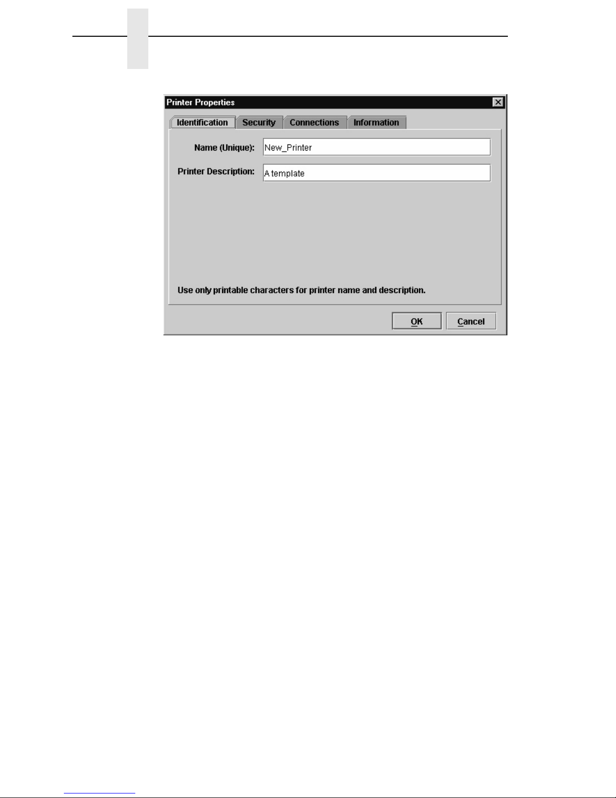
Figure 2. Printer Properties: Identification Tab
3. Double-click New_Printer (A template). The Printer Properties dialog
box opens. See Figure 2.
4. Assign a name to your printer. Delete the words New_Printer in the
Name (Unique) field, and then type Tutorial.
5. Assign a description to this printer. Delete the words A template in the
Printer Description field, and then type My First Connection.
Page 19

19
Figure 3. Printer Properties: Security Tab
6. Click the Security tab. See Figure 3.
7. If you are using the PMU for the first time, it is likely that no passwords are
assigned to this printer. If you are unsure, contact your system
administrator.
• If no passwords are assigned, leave the password boxes empty.
• If a User password is necessary to access this printer, type the password
in the User Password field.
• If a Supervisor password is necessary to access this printer, type the
password in the Supervisor Password field, and check the Supervisor
Mode check box.
• If a Telnet guest password is necessary to poll the status of the printer,
type the password in the Telnet Guest Password field. See “Security Tab”
on page 58.
• If a Telnet root password is necessary to update wireless printer settings,
type the password in the Telnet Root Password field. See “Security Tab”
on page 58.
In any case, an asterisk (*) character appears in the field after each letter
you type to preserve password secrecy.
For more details on setting up and changing passwords, see page 51.
Page 20

20
Chapter 1 Getting Started
Figure 4. Printer Properties: Connections Tab – Network Sub-Tab
8. Click the Connections tab. By default, the Network sub-tab displays.
9. Click the IP Address field and then type the IP Address of the printer you
want to access. Follow the format shown in Figure 4.
The Port Number field must be set to the same port as the printer. Leave
it set at 3001. Leave the Time Out (5..300 seconds) field set at 15
seconds.
Page 21

21
Figure 5. Connections: Connections Tab – Access Method Sub-Tab
10. Click the Access Method sub-tab. See Figure 5.
The Access Method tells the PMU how the host computer communicates
with the printer. Make sure it is set to Ethernet. Ignore Download Mode
and Download Timeout for now. These options are described in “Access
Method Sub-Tab” on page 61.
Page 22

22
Chapter 1 Getting Started
Figure 6. Printer Database Main Window
11. Click OK. The Printer Properties dialog box closes and you return to the
printer database main window. See Figure 6. Your printer is now set up in
the PMU database.
12. Try to access the virtual operator panel as a test to see if the information
you input is accurate. Follow this procedure:
a. Tutorial (My First Connection) should be highlighted in blue, as
shown in Figure 6. If it is not highlighted, click it to select it.
b. Select Applications
Operator Panel. The virtual operator panel
appears (see “Operator Panel” on page 108). If not, an error
message appears in the Status and Error Log pane. Check your
password to make sure it is correct. If the error continues, contact
your system administrator.
Page 23

23
2 Printer Database
Overview
When you start the PMU, the printer database window appears first. The
printer database tool organizes and controls printers and Download files.
Figure 7 shows how the database looks when the PMU launches for the first
time.
Figure 7. Printer Database Main Window
The menu bar contains all the menus used to control the functions of the
program. The menus are described later in this chapter.
The toolbar contains buttons for the most commonly used menu functions.
See page 53 for descriptions of the toolbar buttons.
Use the Database pane to access and control your printers in a tree format.
The first line of the database tree displays the database file name. In Figure 7,
the default file name for this database is default.pdb. From there, your
database tree branches out to include printers, folders, and Download files,
which you can organize into groups. With a single mouse click, you can
Menu Bar
Toolbar
Database Pane
Status and Error Log Pane
Status Bar
Polling Indicator
Page 24

24
Chapter 2 Overview
download a file to several printers at once. In addition, you can use as many
databases with the PMU as you want. Databases save as .pdb files on your
local hard drive.
NOTE: You can open only one printer database at a time.
The Status and Error Log scrolls status and error messages as you work
through the program. If the PMU does not function properly, look at this pane
for error messages. Use the scroll bar on the side of the pane to reference
previous status and error messages. The status and error messages relate to
the current PMU session, not to the specific database. When you exit the
PMU, these messages will be deleted.
The Status Bar displays brief status messages of the PMU, some of which
appear in the Status and Error Log.
The Polling Indicator turns green whenever printers are being polled.
Page 25
The File Menu
25
The Menu Bar
The printer database menu bar is located at the top of the window
(see Figure 7). Use the menu bar to access all the functions of the PMU.
The following are descriptions of the options located on the menu bar.
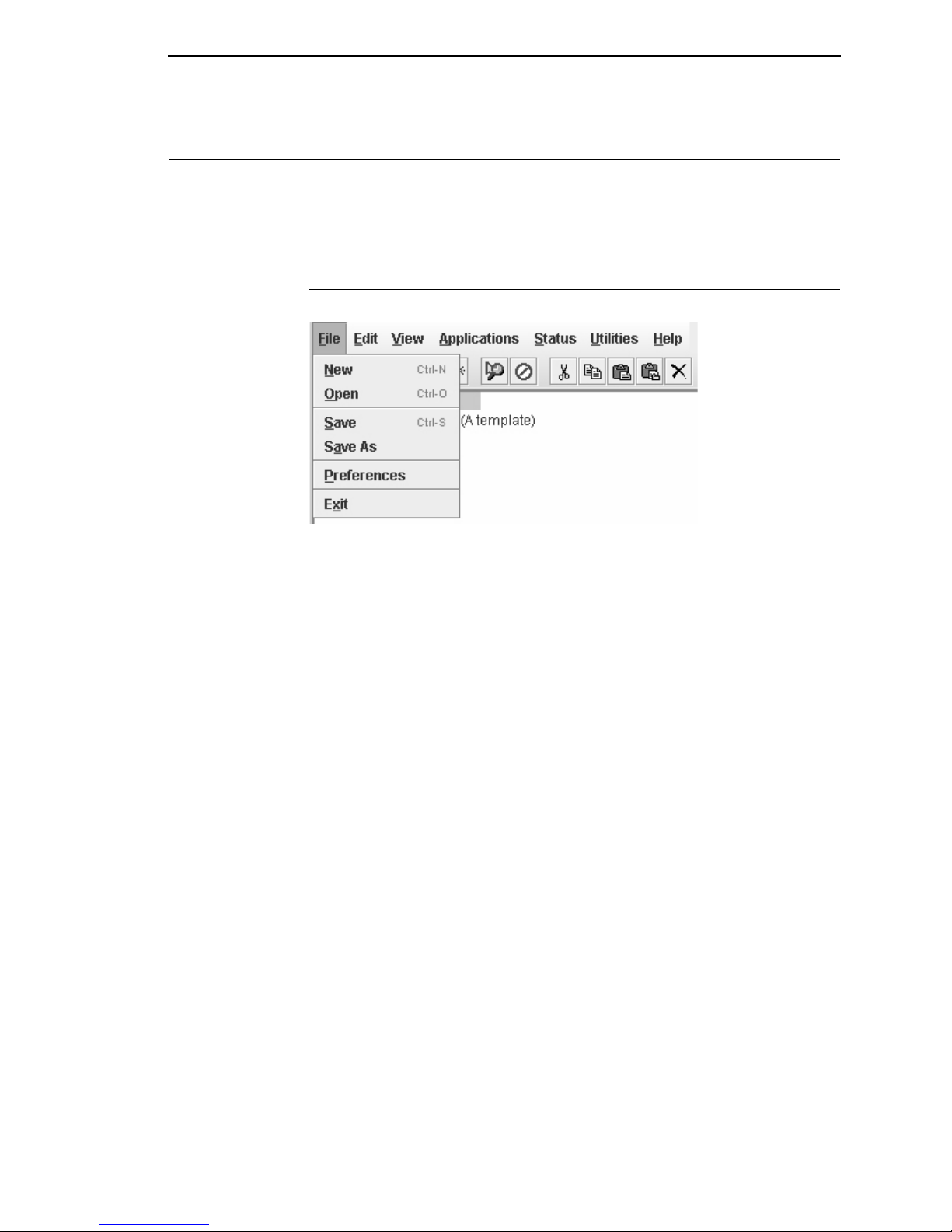
The File Menu
Figure 8. File Menu
New
Creates a new database file. Since the PMU allows only one database file to
be open at a time, it asks if you want to save your changes to the current
database before it creates a new one.
Open
Opens a database file. Since the PMU allows only one database file to be
open at a time, it asks if you want to save your changes to the current
database before it opens a different one.
Save
Saves the active database file using its current name.
Save As
Prompts you to enter a name for the current database file before the PMU
saves it. Use Save As if you do not want to overwrite the current database file.
Preferences
Opens the Preferences dialog box. See page 26.
Exit
Exits the PMU.
Page 26

26
Chapter 2 The Menu Bar
Preferences
The Preferences dialog box has three tabs: Printer Database, Configuration
Editor, and Servers. See Figure 9.
Printer Database Tab
Figure 9. Preferences: Printer Database Tab
The Printer Database tab controls database features.
Database File Name: Enter the name of the default database file. The PMU
opens this database file when the program starts. To select a new default
database file, type it into the Database File Name field, or click Browse to
locate a file on your network.
Lease Time on Printer Connection: Enter an amount (in seconds) to set the
maximum amount of time a printer connection can remain open without any
communication. The default is three seconds.
Security: Check the Show message when the printer is not protected
check box to enable a warning message that informs you when a selected
printer does not have an assigned password.
Page 27

Preferences
27
Configuration Editor Tab
Figure 10. Preferences: Configuration Editor Tab
The Configuration Editor tab controls features of the Configuration Editor
utility.
Hide Key/Unhide Key: Assigns which keys hide and unhide menu items in
the Configuration Editor menu tree (see page 67). The default for Hide is H h.
The default for Unhide is U u.
Dec./Inc. Key: Assigns which keys will decrement and increment menu items
in the Configuration Editor menu tree (see page 67). The default for
decrement is < ,. The default for increment is > ..
Page 28

28
Chapter 2 The Menu Bar
Servers Tab
Figure 11. Preferences: Servers Tab
The Servers tab allows you to assign port values for the SNMP (Simple
Network Management Protocol) Trap Server, the Web Server, and the XML
Server. Click Service Enabled next to the corresponding server to turn it on.
NOTE: You must restart the PMU to use the new settings and enable the
servers.
SNMP Trap Server: The service that enables the PMU to receive alerts from
the printer when its status changes. Once the PMU receives the alert, the
PMU creates an instant status poll to reflect the change in the database pane.
For instance, if you turn the printer offline, the printer sends an alert to the
PMU causing it to change the printer status instantly. In the database pane,
the printer status changes to offline.
NOTE: The SNMP Trap Server works only if the printer’s Ethernet Interface
is configured correctly using the Configure Print Servers utility. See
“Configure Print Servers” on page 145.
Web Server: Allows you to view the active PMU using a web browser. See
“Web Access” on page 121.
NOTE: If you want to use the Web Server service, you must also enable the
XML Server service.
XML Server: The PMU uses XML to communicate with its web server.
Page 29

Preferences
29
Macro Settings Tab
Figure 12. Preferences: Macro Settings Tab – General Sub-Tab
The Macro Settings tab has three sub-tabs: General, Network, and Serial.
See Figure 12.
General Sub-Tab
Macro Config File: Displays the macro file that will load automatically when
you start the macro utility. To select a new default macro config file, type it into
the Macro Config File field, or click Browse to locate a file on your network.
Printer Port: Allows you to select the port that data is sent through. The
choices vary according to the host computer. Possible choices include LPT1,
LPT2, COM1, COM2, and Network.
If you select COM1 or COM2, click the Serial tab to further define printer
parameters. If you select Network, click the Network tab to further define the
network parameters.
• Use selected network printer: Check this box to send data directly to
the network printer selected in the printer database. You do not need to
further define network parameters.
• Rescan: Checks to see which ports are currently available on the host
computer.
Page 30

30
Chapter 2 The Menu Bar
Figure 13. Preferences: Macro Settings Tab – Network Sub-Tab
Network Sub-Tab
Use the Network tab only when the Printer Port on the General tab is set to
Network.
IP Address: The address of the printer where the PMU will send the data.
Port: The port number that the PMU will use to send the data. This must
match the Ethernet Interface of the printer where the PMU will send the data.
In most cases this is 9100, the default. If not, contact your system
administrator.
Page 31

Preferences
31
Figure 14. Preferences: Macro Settings Tab – Serial Sub-Tab
Serial Sub-Tab
Speed: The baud rate at which data transfers. This setting must match the
speed of the printer host serial port under the SERIAL PORT menu (thermal
printers) or the SERIAL submenu in the HOST INTERFACE menu (all other
printer models). See “Serial Port” (thermal) or “Host Interface” (all others) in
your
User’s Manual
.
Word Size: The number of data bits per character. In most cases this should
be set to 8.
Stop Bits: Inter-character gap. Can be set to 1 or 2. The normal setting is 1.
Parity: Adds an error checking bit if set to Odd or Even. The default is None.
Other settings include Mark and Space.
Flow Control: Prevents data overrun by adjusting the sending side according
to the needs of the receiving side.
• None: No adjustment occurs.
• Rts/Cts in: Hardware flow control on serial-input.
• Rts/Cts out: Hardware flow control on serial-output.
• Xon/Xoff in: Software flow control on serial-input using the X-on and
X-off control characters.
• Xon/Xoff out: Software flow control on serial-output using the X-on and
X-off control characters.
Page 32

32
Chapter 2 The Menu Bar
The Edit Menu
Figure 15. Edit Menu
Use the Edit option on the menu bar to build your database. The options in the
Edit menu are described below.
Insert
Adds a folder, printer, or Download file into your database. You must select an
existing database item to create a folder, printer, or file. You can also paste
the contents of the paste buffer (the last item that was copied or cut) into the
database. The new icon appears one level below the selected database item.
If there are items below the selected database item, the new item appears at
the end.
Inserting an item involves three steps:
1. Select a database item. (The new icon will appear below the item you
select.)
2. Define which type of icon you want to add. Select Edit
Insertand then
select the item you want to add. Or click the (insert new folder),
(insert new printer), or (insert new Download file) icon.
A new icon appears in the database.
3. Define what printer, folder, or file this icon represents.
a. To define a printer, see “Defining Printer Properties” on page 56.
b. To define a folder, double-click New Folder. The Folder Name dialog
box opens. Type the name of the folder and click OK.
c. To define a Download file, see “File Download” on page 86.
Cut
Removes selected folders, printers, or files from the database and places it in
the paste buffer.
Copy
Copies selected folders, printers, or files from the database to the paste
buffer, leaving the original intact.
NOTE: You can select multiple database items by using the Ctrl or Shift key.
Page 33

The View Menu
33
Paste
Places the item in the paste buffer on the database tree. To paste, you must
select a database item. The pasted item appears on the same level as the
selected database item.
NOTE: If you select Edit
Paste, the pasted item appears on the same level
as the selected database item. However, if you select Edit
Insert
Paste Buffer, the pasted item appears one level below the selected
database item.
Delete
Permanently removes a selected folder, printer, or file from the database.
Include/Exclude
Deactivates a selected folder, printer, or file. Inactive database items display a
red circle with a slash through it on top of the item’s icon.
You cannot send information to or receive information from excluded
database items using the following Applications, Status, and Utilities menu
options: Flash File Manager, File Download, Update Status, and Configure
Print Servers.
To activate a database item, select the inactive item and then select
Edit
Include/Exclude.
The View Menu
Figure 16. View Menu
Collapse Tree
Collapses all folders on the database menu tree. Only the top level menu
items display.
Expand Tree
Expands all folders and printers on the database menu tree. All folders,
printers, and Download files display.
Page 34

34
Chapter 2 The Menu Bar
Style
Angled Lines: Shows the links between database items using angled lines.
Figure 17. Angled Lines
Horizontal Lines: Shows the links between folders using horizontal lines.
Figure 18. Horizontal Lines
Page 35

The View Menu
35
No Lines: Shows no lines between database items.
Figure 19. No Lines
Page 36

36
Chapter 2 The Menu Bar
Toolbar
Allows you to select which buttons display on the toolbar.
NOTE: By default, some icons do not appear in the toolbar.
For a description of the toolbar icons, see “The Toolbar” on page 53.
Figure 20. Customize Toolbar
Page 37

The Applications Menu
37
The Applications Menu
Figure 21. Applications Menu
For an explanation of the Applications menu options, find the menu option in
Table 2 and go to the corresponding page.
Table 2. Applications Menu Options
Menu Option Page
Configuration Editor page 67
Flash File Manager page 82
CST Manager page 147
File Download page 86
Media Profiler page 100
Operator Panel page 108
Information Capture page 112
Factory Differences page 77
ODV Quality Wizard page 115
Speed Keys page 116
Job Capture page 117
Page 38

38
Chapter 2 The Menu Bar
The Status Menu
Figure 22. Status Menu
Discover Printers
To search for printers on a network, select StatusDiscover Printers, or
click the Discover Printers button at the far right of the toolbar. The
results of the search display in the database pane.
Discover Printers searches for printers on a network based on the settings
specified in the Discovery tab of the Status Monitoring Properties dialog box.
The next section explains how to configure your search.
Page 39

The Status Menu
39
Properties
Select StatusProperties to open the Status Monitoring Properties dialog
box. The dialog box contains three tabs: Discovery, Polling, and Alert
Delivery.
NOTE: To enable printer discovery, check the Enable Printer Discovery
check box.
Figure 23. Status Monitoring Properties:
Discovery Tab – Print Server Discovery Sub-Tab
Discovery Tab
You can discover printers on a network in three ways:
1. Print Server Discovery: This option allows you to discover all InfoPrint
4400/6400/6500/6700/6700-M40 Series Ethernet Interface-equipped
printers on a subnet. To enable the option, check the Enable Print
Server Discovery check box in the Status Monitoring Properties dialog
box (see Figure 23), then click Apply or OK.
Response Wait (Seconds): To specify the time delay (in seconds) the
PMU waits for a printer response. By default, the value is set at 5
seconds.
Broadcast IP, Subnet Mask, and Return Gateway: These settings must
match your network configuration. See your system administrator.
NOTE: To discover unconfigured Ethernet Interfaces, you must enter the
Gateway Address and Subnet Mask in the Return Gateway field.
Page 40

40
Chapter 2 The Menu Bar
Figure 24. Print Server Discovery in Progress
If Enable Print Server Discovery is enabled, a progress indicator displays
while the PMU discovers printers. See Figure 24.
Page 41

The Status Menu
41
Figure 25. Status Monitoring Properties:
Discovery Tab – Polled Discovery Sub-Tab
2. Polled Discovery: This option allows you to select a range of IP
addresses to poll. To enable the option, click the Polled Discovery tab
and check the Enable Polled Discovery check box, then click Add (see
Figure 25). In the First IP Address field, enter the first IP address of your
desired range. In the Last IP Address field, enter the last IP address. Click
Apply or OK. The PMU polls the printers within your specified range and
displays the results in the database pane.
If Polled Discovery is enabled, a progress indicator displays while the
PMU discovers printers. See Figure 26.
Figure 26. Polled Discovery in Progress
Page 42

42
Chapter 2 The Menu Bar
Figure 27. Status Monitoring Properties:
Discovery Tab – Known Printers Discovery Sub-Tab
3. Known Printers Discovery: This option logs previously discovered
printer IP addresses. From this log, you can select and delete previously
polled discoveries to create a new polling list to target your printer search.
To enable the option, click the Known Printers Discovery tab and check
the Enable Known Printers Discovery check box (see Figure 27). From
the polled list of IP addresses, refine your search by keeping or deleting
found IP addresses. Click Apply or OK to start a new poll based on your
specification.
NOTE: You cannot manually add an IP address to this list. If you delete an IP
address, it is lost until it is rediscovered.
If Known Printers Discovery is enabled, a progress indicator displays
while the PMU discovers printers. See Figure 28.
Figure 28. Known Printers Discovery in Progress
Page 43

The Status Menu
43
Polling Tab
Figure 29. Status Monitoring Properties: Polling Tab
The Polling option allows you to control the way the PMU polls printers on the
network. For instance, you can create a timed interval for the PMU to poll
every 30 seconds or every two minutes. You can also specify a range of IP
addresses.
To enable the option, check the Enable Status Monitoring check box in the
Polling tab (see Figure 29). The SNMP Pacing (MS) value places a delay
between each SNMP request. This feature minimizes the network load. By
default, the value is set at 100 milliseconds (.1 second).
NOTE: If Discovery is enabled, then a discovery also occurs, based upon the
settings in the Discovery tab (see “Discovery Tab” on page 39).
Now you can set parameters to a new task. The parameters include:
Printer/Folder: To select which printer or folder you want the PMU to poll.
Click the field to select options from a drop-down menu.
First IP: To set the beginning IP address in a polling range. Use this option if
you select Range: as the Printer/Folder option.
Last IP: To set the last IP address in a polling range. Use this option if you
select Range: as the Printer/Folder option.
Page 44

44
Chapter 2 The Menu Bar
Enable: To select whether or not you want to enable polling of a specific task.
If you want the PMU to poll the printers according to the specifications of your
first task, select true. Otherwise, select false.
Initial Delay (S): To specify the time delay from when the PMU starts to when
the PMU polls printers. The time delay is calculated in seconds.
Polled Interval (S): To poll printers automatically with timed intervals
calculated in seconds. Use this option to periodically poll for new printers
every few seconds.
Response Wait (MS): To specify the time delay the PMU waits between
SNMP responses. By default, the value is set at 300 milliseconds
(.3 seconds).
NOTE: If your network is overloaded and the responses are slow, you may
not receive a response with the default setting. In this case, increase
your Response Wait (MS) value.
NOTE: If you enter a low value for slow networks, you may receive no
response. In this case, increase the Response Wait (MS) value.
Page 45

The Status Menu
45
Alert Delivery Tab
Figure 30. Status Monitoring Properties:
Alert Delivery Tab – Alert Log Sub-Tab
Select Status
Properties to open the Status Monitoring Properties dialog
box. Click the Alert Delivery tab. Check the Enable Notification check box
to enable the option. The Alert Delivery properties allow you to customize the
way the PMU notifies you of potential printer errors. Descriptions of the three
alert types follows:
1. Alert Log: Allows the PMU to log alerts to a file located in the PMU
installation directory. To log alerts, check the Enable Log File check box,
then click Add (see Figure 30). A task item adds to the log list. In the task
item, specify the following as applicable, then click Apply or OK.
Log File: To name the log file. The default file name is alerts.log.
Size: To set the maximum file size, in bytes. The default (and
minimum required) size is 1000 bytes.
Device: To choose a device item you want the PMU to monitor, such
as a folder, specific printer, or a range of IP addresses.
First: To set the beginning IP address in a polling range. Use this
option if you select Range: as the Device option.
Last: To set the last IP address in a polling range. Use this option if
you select Range: as the Device option.
Page 46

46
Chapter 2 The Menu Bar
NOTE: In the remaining alert option fields, select enable or disable as
desired.
Offline, Warning, Media Input, Media Output, Media Path, Marker,
Cutter, Barcode, RFID, Scanner, Label, Intervention Needed,
Consumables, and Power Cart: For a description of the alert groups
and printer events, refer to “Alert Groups” in the SNMP Configuration
section of chapter three in the
Ethernet Interface User’s Manual
. All
options are enabled by default.
To set up alert groups on the Ethernet Interface, see “Configure Print
Servers” on page 145.
Comment: Enter comments as needed.
Figure 31. Status Monitoring Properties:
Alert Delivery Tab – Email Alerts Sub-Tab
2. Email Alerts: The PMU sends you an alert e-mail if a printer error occurs.
To set up Email Alerts, check the Enable Email check box. Enter
information in the following fields:
Outgoing Mail (SMTP) Server: See your system administrator.
Email Subject: Enter the subject of e-mail.
Email Sender: Enter your e-mail address.
SMTP Email Server Port: See your system administrator.
Page 47

The Status Menu
47
Next, click Add to define a new task (see Figure 31). In the new task item,
specify the following information, then click Apply or OK.
Email Address: Enter the e-mail address where you want the PMU
to send the alert messages.
Device: To choose a device item you want the PMU to monitor, such
as a folder, specific printer, or a range of IP addresses.
First: To set the beginning IP address in a polling range. Use this
option if you select Range: as the Device option.
Last: To set the last IP address in a polling range. Use this option if
you select Range: as the Device option.
NOTE: In the remaining alert option fields, select enable or disable as
desired.
Offline, Warning, Media Input, Media Output, Media Path, Marker,
Cutter, Barcode, RFID, Scanner, Label, Intervention Needed,
Consumables, and Power Cart: For a description of the alert groups
and printer events, refer to “Alert Groups” in the SNMP Configuration
section of chapter three in the
Ethernet Interface User’s Manual
. All
options are enabled by default.
Comment: Enter comments as needed.
Figure 32. Status Monitoring Properties:
Alert Delivery Tab – Syslog Posting Sub-Tab
Page 48

48
Chapter 2 The Menu Bar
3. Syslog Posting: Used in a UNIX operating system, it allows the PMU to
log alerts to a file located in the PMU installation directory. To log alerts,
check the Enable Syslog check box, then click Add (see Figure 32). A
task item adds to the log list. In the task item, specify the following as
applicable, then click Apply or OK.
Machine Address: The UNIX IP Address.
Port: See your system administrator.
Device: To choose a device item that you want the PMU to monitor,
such as a folder, specific printer, or a range of IP addresses.
First: To set the beginning IP address in a polling range. Use this
option if you select Range: as the Device option.
Last: To set the last IP address in a polling range. Use this option if
you select Range: as the Device option.
NOTE: In the remaining alert option fields, select enable or disable as
desired.
Offline, Warning, Media Input, Media Output, Media Path, Marker,
Cutter, Barcode, RFID, Scanner, Label, Intervention Needed,
Consumables, and Power Cart: For a description of the alert groups
and printer events, refer to “Alert Groups” in the SNMP Configuration
section of chapter three in the
Ethernet Interface User’s Manual
. All
options are enabled by default.
Comment: Enter comments as needed.
Page 49

The Status Menu
49
Update Status
Update Status shows the condition of the printer at the time the status is
checked. To update the status of a printer, select Status
Update Status, or
click the (green flag) button at the right of the toolbar.
Figure 33 shows a printer with a wireless Ethernet Interface that uses two
ports. The (signal strength) icon represents the wireless port, while the
(ethernet port) icon represents the ethernet port.
The printer’s model number, if available, displays in brackets following the
printer icons. The printer name is a user defined field that is used to
distinguish a printer in the database. This field can be modified in the Printer
Properties dialog box under the Identification tab. The name chosen must be
unique from all the other printer names in the database and must use
printable ASCII characters.
Figure 33. Update Status
When the printer status updates, the (printer) icon may change color:
• Green indicates the printer is online, functioning properly, and can print
• Yellow indicates a warning, but the printer can print
• Red indicates the printer is offline or not functioning properly and cannot
print
• Grey indicates that the printer is not recognized
The message to the right of the printer description is identical to the message
on the operator panel.
If you enable status polling, the printer status updates automatically.
The (ribbon supply) icon indicates the amount of ribbon available on the
printer.
• Green indicates a full or nearly full ribbon supply
• Yellow indicates a moderate ribbon supply
• Red indicates a small or no ribbon supply
• Grey indicates one of the following:
• The ribbon supply feature is not supported on the printer
• For thermal printers, the printer is not using ribbon but rather direct
thermal
• For thermal printers, the printer has not printed since it was powered
on, so the PMU cannot determine the amount of ribbon remaining
• For line matrix printers, the printer was powered on with a fault
condition (not allowing the ribbon to be activated), so the PMU cannot
determine the amount of ribbon remaining
Page 50

50
Chapter 2 The Menu Bar
•
For line matrix printers, the amount of ribbon remaining has reached 0%
(you can still print depending on the operator panel settings)
• Dark grey (line matrix printers only) indicates that the amount of ribbon
remaining has reached 25%
NOTE: The following three icons appear only if the features are installed.
The (signal strength) icon indicates the strength of the radio signal.
• Green with three or four bars indicates a strong signal
• Yellow with two bars indicates a moderate signal
• Red with one bar indicates a weak or non-existent signal
The (ethernet port) icon always remains blue, since it represents an
ethernet connection.
The (battery power) icon indicates the percentage of available battery
power.
• Green indicates the battery has 61% to 100% available power
• Yellow indicates the battery has 20% to 60% available power
• Red indicates the battery has less than 20% available power
Place the pointer over the , , or icon to obtain status information
about the feature. See Figure 34, Figure 35, and Figure 36.
NOTE: No information displays if you place the pointer over the icon.
Figure 34. The Ribbon Supply Icon
Page 51

The Utilities Menu
51
Figure 35. The Signal Strength Icon
Figure 36. The Battery Power Icon
The Utilities Menu
Figure 37. Utilities Menu
For an explanation of the Utilities menu options, find the menu option in
Table 2 and go to the corresponding page.
Page 52

52
Chapter 2 The Menu Bar
The Help Menu
Figure 38. Help Menu
About
Displays the About dialog box. The About dialog box shows the PMU
program’s version information and part number, and the Java version
number.
Table 3. Utilities Menu Options
Menu Option Page
Reboot Printer page 127
Set Printer Password page 127
Set Wireless Properties page 129
Macro Utility page 138
SNMP Browser page 141
Assign IP Address page 142
Enable Remote Printer
Management
page 143
Lock/Unlock Menus page 144
Configure Print Servers page 145
Page 53

The Help Menu
53
The Toolbar
The PMU toolbar contains buttons that perform functions. See below for a
description of each button. Refer to the specified page for a more detailed
description.
You can select which buttons display on the toolbar. See page 36.
Button Description
Open: Opens a different printer database.
Save: Saves the current printer database.
Folder: Inserts a new folder into the printer database
(page 32).
Printer: Inserts a new printer into the database
(page 32).
Download File: Inserts a new Download file into the
database (page 32).
Edit: Defines the properties of the selected item
(page 56).
Include/Exclude: Deactivates a selected folder, printer,
or file (page 33).
Cut: Removes a selected folder, printer, or file from the
database and places it in the paste buffer (page 32).
Copy: Copies a selected folder, printer, or file to the
paste buffer (page 32).
Paste After: Pastes the item in the paste buffer after the
selected item (page 33).
Paste Into: Pastes the item in the paste buffer into the
selected item (page 33).
Delete: Removes the selected item (page 33).
Operator Panel: Virtual operator panel that allows you
to make selections via the PMU as if you are using the
physical operator panel (page 108).
Information Capture: Allows the PMU to capture
information sent between the computer and the printer
(page 112).
Configuration Editor: Allows you to edit the data sent
from the computer to the printer before the printer
receives it (page 67).
Page 54

54
Chapter 2 The Toolbar
Find Differences: Allows you to find the differences
from the factory settings for all configurations (page 77).
File Download: Allows you to download a configuration,
firmware, or flash file to the printer (page 86).
ODV Quality Wizard: Opens the ODV Quality Wizard
window (page 115).
Configure Print Servers: Opens the Configure Print
Servers window (page 145).
Speed Keys: Opens the Speed Keys window
(page 116).
Flash File Manager: Opens the Flash File Manager
window (page 82).
Media Profiler: Opens the Media Profiler window
(page 100).
CST Manager: Opens the CST Manager window
(page 147).
Job Capture: Opens the Job Capture window
(page 117).
Macro Utility: Opens the Macro Utility window
(page 138).
Update Status: Marks a printer or printers for status
updates (page 49).
Discover Printers: Searches for new printers (page 38).
Button Description
Page 55

Database Items
55
Managing the Database
To organize your databases easily and effectively, use the Edit option on the
printer database menu bar. You can add, delete, and assign printers,
configuration files, and download files to your database tree. You can also
organize them using folders. All Edit menu functions have buttons on the
toolbar (see page 53).
Database Items
Folder: Use folders to group the elements of your database.
Printer: See “Defining Printer Properties” on page 56.
Download file: A flash file or a configuration file (created in the
Configuration Editor which is described on page 67) stored on your
host computer.
A flash file contains information (e.g., the printer’s firmware file or a font
file) that you can download to the flash SIMM memory of a printer or
group of printers.
A configuration file contains user-defined printer configurations that you
can download to your printer using either the printer database or the
Configuration Editor.
For information about Download files, see “File Download” on page 86.
Page 56

56
Chapter 2 Managing the Database
Defining Printer Properties
Figure 39. Defining Printer Properties
Before you can use any of the PMU applications, you must define the printer’s
properties. You must identify the printer and configure how the printer
communicates with the PMU. To define a printer, double-click the printer’s
name or click the (edit database entry) button. The first time you run the
PMU, double-click New_Printer (A template). The Printer Properties dialog
box opens. See Figure 39.
The Printer Properties dialog box contains four tabs: Identification, Security,
Connections, and Information, described in the next sections.
Page 57

Defining Printer Properties
57
Identification Tab
Figure 40. Printer Properties: Identification Tab
Name (Unique)/Printer Description: Assigns a name to your printer to
identify it in the printer database. You can also assign a printer description,
which appears in parentheses to the right of the printer name in the database.
When you assign a printer name and description, use only printable
characters. Spaces may be used to separate words.
Page 58

58
Chapter 2 Managing the Database
Security Tab
Figure 41. Printer Properties: Security Tab
User/Supervisor Password: Enter the printer’s password, if appropriate.
The password feature restricts access to certain functions of the PMU. In
User mode, the PMU does not allow the following functions: downloading
files, configurations, or configuration names to the printer; clearing the error
log; and setting passwords. Supervisor mode allows unrestricted access to all
functions of the PMU.
User and Supervisor passwords are only recognized up to 9 characters, and
are displayed as *****, one * for each character typed. Use only printable
characters for passwords. Spaces may be used to separate words. To set up
a password, see “Set Printer Password” on page 127.
Telnet Guest Password: The PMU uses Telnet to read various printer
settings.
IMPORTANT
If you change the Telnet guest password, click OK and then the
(green flag) button (or select Status
Update Status).
Telnet Root Password: The PMU uses Telnet to update various printer
settings.
IMPORTANT
If you change the Telnet root password, click OK and then the
(green flag) button (or select Status
Update Status).
Page 59

Defining Printer Properties
59
Telnet Guest Password Errors
Figure 42. Telnet Guest Password Error: Polling the Printer Status
The PMU uses Telnet to poll the printer status. If your printer reports a Telnet
error (see Figure 42), enter the password for the user guest (page 58).
See your system administrator.
Figure 43. Telnet Guest Password Error: Reading Wireless Settings
The PMU also uses Telnet to read wireless printer settings (page 129). If the
PMU reports a Telnet error when attempting to read wireless printer settings
(see Figure 43), enter the password for the user guest (page 58).
See your system administrator.
Page 60

60
Chapter 2 Managing the Database
Telnet Root Password Errors
Figure 44. Telnet Root Password Error
If the PMU reports a Telnet error when attempting to update wireless printer
settings (see Figure 44), enter the password for the user root (page 58).
See your system administrator.
Figure 45. Enable Command Failed
The PMU also uses Telnet to enable remote printer management (see
“Enable Remote Printer Management” on page 143).
If the PMU reports an error when attempting to enable remote printer
management (see Figure 45), enter the password for the user root (page 58).
See your system administrator.
Page 61

Defining Printer Properties
61
Connections Tab
Figure 46. Printer Properties:
Connections Tab – Access Method Sub-Tab
The Connections tab contains three sub-tabs: Access Method, Network, and
Serial/Modem.
Access Method Sub-Tab
Access Method: Identifies how the PMU accesses the printer. Refer to the
Ethernet Interface User’s Manual
to set up the Ethernet Interface for your
printer.
• Ethernet: To connect the host computer to the printer via the
Ethernet Interface.
• Network (TCP): To connect the host computer to the printer via a
network interface.
• Printer Serial Port (Direct): To connect the host computer to the
printer directly via the serial port.
• Printer Debug Port (Direct): To connect the host computer to the
printer directly via the debug port.
• Printer Serial Port (Modem): To connect the host computer to the
printer via a modem and the serial port.
• Printer Debug Port (Modem): To connect the host computer to the
printer via a modem and the debug port.
Download Mode: Identifies how the PMU downloads files and configurations
to the printer. Access Method is the only option available.
Printer Timeout on Firmware Download: Specifies the number of minutes
the printer waits for data while downloading a file from the host computer. If a
Page 62

62
Chapter 2 Managing the Database
stall lasts for more than the specified time, the printer times out and the
download terminates. If you have a slow connection between the PMU and
the printer, you may need to define a longer Download Timeout period.
The Download Timeout range is between 1 and 60 minutes. The default is
2minutes.
Firmware Download Initial Delay (Sec): Specifies the number of seconds
the PMU waits before sending files to the printer. If the printer is not ready
within the specified time, the download will terminate, and the Status and
Error Log will report Connection Refused.
If you receive this error message, increase the initial delay time. The default is
60 (seconds).
Network Sub-Tab
Figure 47. Printer Properties: Connections – Network Sub-Tab
Enter the printer’s IP Address and Port Number. (Click Default to reset the
Port Number to 3001.) The Time Out option sets the amount of time, in
seconds, the PMU waits for a response from the printer after sending a
command. If there is no response in the specified amount of time, an error
message appears in the Status and Error Log pane. If you have a slow
connection between the PMU and the printer, you may need to define a
longer Time Out period. Define the Time Out between 5 and 300 seconds (the
default is 15 seconds).
NOTE: The Network settings must match the settings in the operator panel
menu. See “ETHERNET PARAMS”, “ETHERNET ADDRESS”, or
“WIRELESS ADDRESS” in the printer’s
User’s Manual
to check the
IP address.
To check the port number on the printer, see “Check Port Number” on
page 14.
Page 63

Defining Printer Properties
63
Serial/Modem Sub-Tab
The Serial/Modem tab contains two tabs: Serial Port Parameters and Modem
Control.
Serial Port Parameters
Figure 48. Printer Properties: Connections – Serial/Modem Sub-Tab
Serial Port Parameters
Connect Using: The serial port to use for connection. The default is COM1.
The range is COM1 to COM20.
Speed: The baud rate at which data transfers. This setting must match the
speed of the printer serial debug port. See
Table 4 to determine the serial
debug port baud rate menu location for your printer model
Word Size: The number of data bits per character. Must be set to 8 bits.
Parity: Adds an error checking bit if set to Odd or Even. Since the word size
must be set to 8 for correct operation, parity should normally be set to None.
Stop Bits: Inter-character gap. Can be set to 1 or 2. The normal setting is 1.
Table 4. Serial Debug Port Baud Rate Menu Location
Printer Model Menu
6700-M40 Series INTERFACES
Printer MgmtBaud Rate
6700 Series PRINTER MGMT or Factory
Baud Rate
4400 Series FactoryBaud Rate
6500 Series PRINTER MGMT
BAUD RATE
6400 Series SERVICEPRINTER MGMTBAUD RATE
Page 64

64
Chapter 2 Managing the Database
Modem Control
Figure 49. Printer Properties: Connections – Serial/Modem Sub-Tab
Modem Control
Phone Number: Enter the phone number you wish to call.
Dial Method: Choose Tone or Pulse.
Call Back: Enter your phone number, and check Enable if you want to use it
as a call back number.
Page 65

Defining Printer Properties
65
Information Tab
Figure 50. Printer Properties: Information Tab
Contains information about your printer. Refer to the
Ethernet Interface User’s
Manual
for more information.
Page 66

66
Chapter 2 Managing the Database
Page 67

67
3 Applications and
Web Access
Configuration Editor
Figure 51. Configuration Editor Window
To access the Configuration Editor application, select a printer from the
printer database and select Applications
Configuration Editor or click the
(configuration editor) button. Select File
Upload From Printer to upload
configurations from the printer. The configurations upload from the printer and
the active configuration displays in the Configuration Editor window. See
Figure 51.
The Configuration Editor supports offline editing, allowing the editing of stored
configurations. If you start the Configuration Editor without connecting to a
printer, the screen will be blank (indicating no configuration loaded). A
configuration will not display until you load a configuration file from a disk or
computer.
The Configuration Editor allows you to upload, modify, and download eight
user-defined configurations and the factory default configuration (only if
modification of the factory configuration has been enabled; see the NOTE on
page 69). You may also save sets of configurations to your local hard drive so
that they can be easily downloaded to the printer at any time.
The Configuration Editor does not change the current configuration or the
active printer status until the configurations are downloaded to the printer.
Page 68

68
Chapter 3 Configuration Editor
Menu Tree
The Configuration Editor displays the printer configurations in a tree format
(see Figure 51). The top level of the tree is the OFFLINE menu. From this
level, the tree branches into the printer’s submenus. Menu items that have a
or (handle) next to them have further submenus below them. Click the
handle to expand or collapse the submenus below. (You may also use the
Expand Tree/Collapse Tree options in the View menu, but these options will
expand or collapse all submenus.)
The Configuration Editor has three drop-down menus at the bottom. The
Displayed Language option allows you to select from five or more different
languages to display the configuration information. The Displayed
Configuration option lets you choose between the available configurations to
display. The Power-Up Configuration allows you to assign which configuration
loads whenever the printer turns on.
Creating Configurations
Along with the factory configuration, your printer allows up to 8 user-defined
configurations that can be downloaded to your printer’s memory. You may
create configurations using the operator panel or by using the Configuration
Editor.
To create a configuration using the Configuration Editor:
1. Select Edit
Copy From:. A list of configurations appears. Undefined
configurations appear gray. Choose one of the configurations.
2. Click Edit. (Notice that the configuration you chose in step 1 now appears
next to the Copy From: menu item.) Move your mouse down to Copy To.
A list of configurations appears. Choose the number of the configuration
you want to create. This new configuration is created with the settings
from the configuration you chose in step 1.
NOTE: If you choose to Copy To a configuration which already exists, that
configuration will be overwritten.
3. You may now edit the configuration settings. See “Changing
Configurations” on page 69.
Page 69

Changing Configurations
69
Changing Configurations
Configuration settings in the Configuration Editor can be changed two ways:
• make the changes directly on the menu tree
• use the Menu Editor
NOTE: Normally, the factory default configuration cannot be changed.
However, you can enable modification of the factory configuration.
Select Edit
Enable Factory Edit. It is strongly recommended that
you do
not
modify the factory default configuration. If you choose to
modify the factory configuration, you should first upload it from the
printer, and then save it. This way, you will have a backup copy of the
factory configuration. To disable modification of the factory
configuration, select Edit
Disable Factory Edit.
Making Changes on Menu Tree
1. Using the Displayed Configuration menu at the bottom of the window,
click the drop-down arrow to choose the configuration to change.
2. Expand the submenus until the configuration setting you want to change
displays.
3. Select the menu item you want to change. A selection box surrounds your
choice. See Figure 52.
Figure 52. Selecting a Menu Item
4. Double-click an item to open the Menu Editor (page 70) for that item, or
use the < and > keys to toggle through the available options. See
Figure 53. (You may change these keys in the printer database window:
select File
Preferences, then click the Configuration Editor tab.
See page 27.)
Figure 53. Toggling Through The Available Options
Page 70

70
Chapter 3 Configuration Editor
Menu Editor
Figure 54. Menu Editor
Double-click any menu item to open the Menu Editor window. Figure 54
shows the screen you see when you double-click the Printer Protocol option.
By using the Menu Editor, you may view and adjust the settings of all nine of
the printer configurations at once. To change a setting, click the drop-down
arrow underneath the corresponding configuration and choose an option.
Grayed out configuration names and settings do not exist; you must create
the configuration before you can edit it (see page 68).
To hide a menu item in the operator panel, select Hidden under a
configuration. Click Hide All to hide this menu item in all configurations. (For
more information on hiding, see page 71.)
Select Copy Fact (1-8) to set all configurations to the same value as the
factory or user-defined configuration currently selected under the
Edit
Copy From: menu in the Configuration Editor (see page 68).
Click Cancel to exit the Menu Editor without saving your changes.
Click Apply to save your changes without exiting the Menu Editor.
Click OK to save your changes and exit the Menu Editor.
Deleting Configurations
To delete any of the configurations (except the factory configuration), select
Edit
Deleteand choose the number of the configuration to be deleted.
Naming Configurations
You may name any of the eight user-defined configurations using an
alphanumeric string of 1 to 15 characters. Select Edit
Names to open the
Edit Configuration Names window.
Choose the configuration you want to name, then click OK to assign the name
change, Cancel to exit this window without saving your changes, or Reset to
restore the original configuration numbers.
Page 71

Changing Configurations
71
Hiding/Unhiding Menu Items
Figure 55. Hiding a Menu Item
The Configuration Editor allows you to hide menus to make the operator
panel menus easier to use, or to restrict printer operators from accessing
certain printer configuration menu items. If you choose to hide a menu item in
the Configuration Editor, the hidden menu item still loads into the printer when
the configuration downloads to it. However, the hidden menu item does not
appear on the operator panel.
The Configuration Editor displays hidden menus in gray on the menu tree.
When a menu item is hidden, all of its sub-menus are hidden as well.
In Figure 55, the Display Language menu item is hidden. The Display
Language menu item cannot be changed from the operator panel.
IMPORTANT
Depending upon the active emulation, active interface, or hardware
attached to the printer, some menu items cannot be hidden on the
operator panel, even though they may be defined as “hidden” in the
PMU.
You can still change hidden menu items using the Menu Editor.
You can hide or unhide menu items in three ways:
1. In the menu bar, select View
Hide/Unhide Menus. With this menu
option, you may hide or unhide individual items, sub-menus or the entire
configuration.
2. Using the Menu Editor. See page 70.
3. Using the keyboard. From the menu tree, select a menu item. A selection
box appears around the selected menu item. Press H to hide the menu
item or U to unhide the menu item. (To change these keys, select
File
Preferences in the printer database window. See page 27.)
Page 72

72
Chapter 3 Configuration Editor
Saving Configuration Files
Normally, your printer can save only nine configurations in its memory. You
change these configurations through the operator panel. However, using the
PMU, you can store a nearly unlimited number of configurations on your host
computer.
Once you have made your changes, you can save your configurations as a
.cfg file on your local hard drive. This way, you can open any set of
configurations from your host computer and download them into your printer
quickly and easily.
To save configurations to your local hard drive, select File
Save As. Be sure
to save your configuration as a .cfg
file.
Opening Configuration Files
To open a configuration file, select FileOpen. The Configuration Editor
loads the settings from the file you choose.
IMPORTANT
These settings do not affect the current configuration or the active
printer status until the configurations are downloaded to the printer.
NOTE:
The Configuration Editor displays only one configuration file at a time.
Be sure to save any changes before opening another configuration file.
If you load a configuration file that was created with the PMU version 3.03H or
earlier, you may need to link the affiliated CST file. In this case, select
File
Open again, and check the Link CST File check box. See Figure 56.
Navigate to the affiliated .cst file and double-click it (or single-click it and click
the Select button). Save the configuration file, and the CST information will
save to the new configuration file. (You will not need to link the CST file in the
future.)
NOTE: If you hover the pointer over the Link CST File check box, a screen
tip appears that describes this functionality.
Figure 56. Linking a CST File
Page 73

Downloading Configurations
73
Downloading Configurations
You may use the Configuration Editor to download into your printer any
configurations you have created. Open the configuration file you want to use,
then select File
Download To Printer to send individual configurations, all
configurations, or just the configuration names.
Downloading a configuration overwrites the corresponding configuration
currently stored in the printer. If you want to save the configurations currently
stored in the printer before overwriting them, upload them into the
Configuration Editor first, and then save them as a .cfg file on your local hard
drive.
NOTE: Be sure to calibrate your thermal printer after you download a
configuration to it. See “Running Auto Calibrate” in the printer’s
User’s Manual
.
Uploading Configurations
The Configuration Editor can upload configurations from a printer. Select
File
Upload From Printer. Once the configurations upload, you can save
them to a file. Now you can select another printer from the database and
upload its configurations. The PMU prompts you to save the previously
uploaded configuration before the new configuration uploads.
Migration
Over time, menus and functions changed to reflect the new features of the
printers. Some printer features have been removed to provide better or more
complete printer features. Older saved configurations may have used these
removed features or contain settings that no longer exist or have been
modified in new printer firmware. This can cause potential problems when
downloading new printer firmware while preserving previously saved
configurations if the saved settings are not analyzed and adjusted to work
with the new firmware. This analysis and adjustment has been summarized
into one word: migration.
Transferring Saved Settings
Original Method
To ensure that your settings from the saved configuration are set correctly in
the printer: print out the old configurations, download the configurations to the
printer, print out the new configurations, and compare the old settings with the
new settings.
If you need to make changes: upload the configurations to the Configuration
Editor, make changes, and re-download to the printer.
Page 74

74
Chapter 3 Configuration Editor
Enhanced Method
Using the migration utility in the Configuration Editor, all these things can be
done without having to download the configurations to the printer until you
know they are correct. No migrated settings will be downloaded to your printer
until you download them. This way you can run the migration, view the results,
view the report, and make any necessary changes without affecting your
saved configurations or the configurations in the printer.
How To Use The Migration Utility
STEP 1:
Load the configurations settings that need to be migrated into the
Configuration Editor before using the migration utility.
Migration Limitations
Only attempt to migrate saved configuration settings from printers of the same
model type and the same emulations. An example of a different printer model
type is a thermal printer configuration to a line matrix printer.
The printer that you are going to migrate the settings to should be a superset
of or contain the same emulations as the saved configurations. For example,
migrate saved settings that contain an ANSI emulation on a line matrix printer
to another line matrix printer that contains ANSI and PGL. Do not migrate
these same saved settings to a line matrix printer that does not contain ANSI.
The migration utility does not prevent you from doing this, but the results
would be useless and could cause problems if the migrated configurations
were downloaded and then loaded on a different printer type.
IMPORTANT
Make sure the printer model type and emulations of the saved
configurations match the printer model type and emulations of the
printer you want to migrate the settings to before attempting to migrate
the saved settings.
Loading Configuration Settings
The configuration settings to migrate can be opened using the Configuration
Editor in the following ways:
Loading From a File
Click the (open configuration file) button or select File
Open. Choose
your configuration file and then click OK.
Loading From a Printer
Select a printer in the printer database. Click the (upload configuration)
button or select the File
Upload From Printer to upload the settings.
Page 75

Migration
75
STEP 2:
Select a printer and begin the migration of the saved configuration
settings.
Select a Printer to Use for Migration
Select a printer in the printer database. The printer you select must have new
printer firmware. If it does not, exit the Configuration Editor and download new
firmware to the selected printer (see “File Download” on page 86), then select
the printer in the printer database.
Start the Migration
Click the (migrate) button or select MigrationRun Migration. Several
messages will appear in the bottom left corner of the Configuration Editor that
indicate the progress of the migration.
STEP 3:
View the results using the Configuration Editor.
The results will display graphically in the Configuration Editor.
Several different icons will display depending on the migration. Hover the
pointer over an icon to display a short description. A icon can represent
several types of changes. The migration report details these changes
(page 76).
Select Migration
View Results to see the migration results.
This menu has the following submenus:
Original Configurations
All Menus: Displays the original configuration settings with the menus that
were removed from the original configurations.
Removed Menus: Displays only the menus that were removed from the
original configurations.
Migrated Configurations
All Menus: Displays the migrated configuration settings including all of the
menus that were modified.
Modified Menus: Displays only the menus that were modified by the
migration of the saved settings.
If you select Modified Menus and then select View
Expand Tree, all of the
menus that were affected by the migration will display in a simplified view.
Migration Icon Definitions
Indicates a new menu or a new set of menus.
Indicates that the menu previously existed in the saved configurations and
was added to another menu.
Page 76

76
Chapter 3 Configuration Editor
Indicates that the menu previously existed in the saved configurations and
was moved to another menu, or removed from the current menu but still exists
in the saved configurations.
Indicates that the menu was completely removed.
Indicates that this menu or a submenu has changed. The change can be
various things such as range or increment.
Indicates that additional selections have been added to this menu.
Indicates that selections have been removed from this menu.
Indicates that this menu has been replaced with another menu or the
menu definition has changed.
STEP 4:
View the results using the Migration Report Viewer.
Select Migration
View Report or double-click the Migration Report
icon (located at the top of the migrated configurations display) to open the
Migration Report Viewer.
The Migration Report Viewer displays a detailed textual report of the
information that displays graphically in the Configuration Editor. Use the
Migration Report Viewer to view, save, or print the report.
NOTE: It is recommended to use landscape mode when printing the
migration report.
The report contains the following types of messages:
Informational Messages: Menu settings that migrated without problems.
They display to inform you that there was a change during the migration.
Warning Messages: Menu settings that attempted to migrate to the new
configurations and were changed. Analyze these settings to determine if they
are desirable.
Intervention Messages: Menu settings that could not migrate to the new
configurations. This could occur when a menu item was completely removed
and the user utilized a setting other than the default. In this case the Migration
Utility cannot decide what action to take.
IMPORTANT
You must resolve intervention messages, or the printer may not operate
properly.
STEP 5:
Post-migration.
After you review the migrated configuration, save, delete, or download the
migrated configuration file to one or more printers using the PMU.
Page 77

Migration
77
Factory Settings Differences
The Factory Settings Differences application allows you to keep track of
migration from old to new printers. It displays the differences between the
Factory configuration settings and all other saved configuration settings. The
differences are highlighted to show value differences between configurations.
Two views displaying the data are available. The All Settings view shows all of
the menus, highlighting the value differences. The Differences Only view
shows the menus and its corresponding values that differ from the Factory
settings.
To access the Factory Settings Differences application, select
Applications
Factory Differences or click the (find differences) button.
The application opens with no configuration data loaded. The Factory
Settings Differences window contains three sections: the menu bar, toolbar,
and the configuration settings differences pane. See Figure 57.
Figure 57. Factory Setting Differences Window
Configuration Settings
Differences Pane
Menu Bar
Toolbar
Page 78

78
Chapter 3 Factory Settings Differences
Menu Bar
The menu bar consists of a File menu and a View menu.
File Menu
Figure 58. Factory Settings Differences – File Menu
Open
The Open submenu allows you to select and open a previously saved Factory
Settings Differences file. The file must be one that was created with this
application.
NOTE: No error checking is available for an invalid file type, including
Comma Separated Variable (CSV) formatted files that were not
created by this application.
Upload Differences
The Upload Differences submenu uploads the configurations and determines
the Factory settings differences. The results display in a table in the All
Settings view.
Save and Save As
The Save and Save As submenu allows you to select and save the Factory
setting differences file to a file. The results table can only be saved in the
Differences Only view. You will be informed if you try saving the file in the All
Settings view. The saved file will be in CSV format.
Print
The Print submenu allows you to set up printing preferences and print the
differences table. You can print the differences table in both views.
Page 79

Toolbar
79
View Menu
Figure 59. Factory Settings Differences – View Menu
All Settings View
The All Settings view displays all of the menus in the configuration,
highlighting the menus that are different from the Factory settings and their
values. The menu name and its associated values are highlighted in different
colors for easy distinction. See page 80.
Differences Only View
The Differences Only view shows the top level menus and the menus that
have configuration values that are different than the Factory settings. Since
this view only shows the differences, the menu names are not highlighted.
The menu values are highlighted for easier distinction. See page 81.
Toolbar
Figure 60. Factory Settings Differences – Toolbar
The toolbar contains buttons for Open, Save, Upload Differences, All Settings
View, Differences Only View and Print. These buttons perform the same
actions as their menu counterparts. The toolbar also has font selection and
size boxes to allow user selectable preferences.
Page 80

80
Chapter 3 Factory Settings Differences
Configuration Settings Differences Views
This view consists of a non-editable table that displays the menu name, the
menu level, the Factory default settings, and the values of other saved
configurations.
The menu level column shows a menu option’s hierarchy level from the top
menu. Number 1 indicates the top menu, and the largest number is the menu
that is the furthest down the menu tree.
All Settings View
In the All Settings View mode, all menus and its corresponding values display
in a table. The menus with values different from the Factory configuration is
highlighted in purple and the value itself is highlighted in yellow.
See Figure 61.
Figure 61. All Settings View
Page 81

Displayed Language
81
Differences Only View
In the Differences Only View mode, only the differences between the Factory
configuration and other menu configurations are listed. The differing values
are highlighted in yellow. The menus are not highlighted.
Figure 62. Differences Only View
Displayed Language
The Displayed Language drop-down menu shows all available foreign
languages that the attached printer supports. Since this depends on the
printer, the drop-down menu will be disabled when the Factory Settings
Differences application is first launched. After the Upload Differences program
is executed, the available language names supported by the printer will
display.
After you select a language, the program determines if it has already been
uploaded, and changes the table settings to this language. If it is not loaded,
the program uploads the selected language and redisplays the table settings
in the new language.
Page 82

82
Chapter 3 Flash File Manager
Flash File Manager
Figure 63. Flash File Manager Window
With the Flash File Manager, you can view a list of the unprotected files
loaded in the printer’s flash memory and optional EMC (Expanded Memory
Cartridge).
NOTE: The EMC is available only for 6700-M40 printers.
You can upload the files to the host computer, save them for backup, delete
them, and download them to another printer.
Select Applications
Flash File Manager or click the (flash file
manager) button. See Figure 63.
The Printer List pane displays a list of printers that are selected in the printer
database. If you select one printer, it appears alone in the list. If you select a
folder, all active printers in the folder appear.
If you return to the printer database and select another printer or folder, click
Refresh to update the Flash File Manager and display the newly selected
printer(s).
NOTE: Cloned printers or different folders that link to the same printer do not
display. Only the original printer displays.
Page 83

Get File Info
83
Get File Info
Figure 64. Get File Info
Select a printer, and then click Get File Info to see a list of the unprotected
files loaded in the printer’s flash memory. Progress displays in the status bar
at the bottom of the window. After you retrieve the flash memory information,
the files appear in the File List pane. See Figure 64.
NOTE: The files are located on the printer’s internal flash memory. If [EMC]
precedes the file name, then the file is located on the optional EMC.
When complete, select another printer and click Get File Info to view its flash
memory information.
You can only view the flash memory information from one printer at a time,
but the Flash File Manager remembers what information has been retrieved.
For printers that have not had flash memory information loaded, the message
FFS (Flash File System) Info Not Loaded displays in the Printer List.
See Figure 64.
NOTE: Although you have retrieved the flash memory information, the files
have not been uploaded. Notice the message “data not loaded” in the
File List. To upload the files, see “Upload” on page 84.
The status bar will toggle from the status of the last operation performed to
the status of the printer flash: memory available (free), memory used (in use),
and memory deleted but not optimized (trashed):
If you have an EMC installed, the status bar will also toggle the status of the
EMC:
Status Bar
NOTE:
Displays only if
the printer has
an EMC installed
Page 84

84
Chapter 3 Flash File Manager
Upload
Figure 65. Uploaded Flash Files
To upload unprotected files, select a printer, and then select the files you want
to upload from the File List. Click Upload to upload the unprotected files from
the flash memory. Progress displays on the status bar at the bottom of the
window.
After the files upload, they appear selected in the File List pane. See
Figure 65. Click Save As to save all the files together as one downloadable
file (bundle file). Save the file with a .pff file extension.
Page 85

Delete And Optimize
85
Figure 66. Selecting Multiple Files
Or, you may use the Shift or Ctrl key to select single or multiple files.
See Figure 66. This way, only the selected files will save to the .pff file when
you click Save As.
NOTE: You can save only uploaded files to a downloadable file.
Delete And Optimize
IMPORTANT
You can not undo a flash file deletion.
You can erase files from the printer’s flash memory. Select the files you want
to delete from the File List, then click Delete. To download files back to the
flash memory, see “File Download” on page 86.
Once you have deleted files, the flash memory is not optimized until you click
Optimize. Optimizing reclaims flash space from deleted flash files.
NOTE: The printer reboots after you Optimize.
To delete and optimize in one step, select the files you want to delete from the
File List, then click Delete & Optimize.
CST Manager
See “Datastream Adapter” on page 147.
Page 86

86
Chapter 3 File Download
File Download
NOTE: The terms download and upload as used here and in the software
indicate the printer’s point of view. Therefore, when you download a
file, you are sending information to the printer (the printer downloads).
When you upload a file, you are receiving information from the printer
(the printer uploads).
IMPORTANT
To utilize the File Download application, make sure Enable Status
Monitoring is checked in the Polling tab (see page 43). Then select your
printer in the printer database and click the update status button to
make sure your printer has been polled at least once (see page 49).
The File Download application allows you to download any of the following file
types (program files, configuration files, recovery files, and flash files) to either
a single printer or to a group of printers in one step. Recovery files are an
exception and should only be downloaded back to the printer that had
problems during a download.
To download a file to a single printer, insert a (Download file) icon below
the printer (one level lower than the printer). To download a file to a group of
printers, insert the Download file icon on the same level as the printers (in the
same folder containing the printers). Use the printer database and insert
additional Download file icons to download as many files to as many printers
as you want.
NOTE: Previous versions of the PMU required different file types to be
downloaded to the printer in separate steps, which is why the various
file types were identified by or icons. With this version of the
software, a distinction between the various file types is not needed,
and a icon identifies all file types. Therefore, if you open a printer
database that was saved using a previous version of the software, all
icons will change to icons.
Page 87

Define The Download Files
87
Define The Download Files
After you insert Download files, you must define them:
1. Double-click New Download File. The Define Download File dialog
box opens. See Figure 67.
2. Click Browse. The Open dialog box opens.
Figure 67. Define Download File
3. Navigate to a program (firmware), configuration, recovery file, or flash file,
select it, then click Open.
4. Since multiple file types can now be downloaded in one operation, a Test
button is provided to allow you to verify if the file type specified is
supported by the printer. Clicking the Test button causes the PMU to
evaluate the specified file and display the file type – this will help you
verify that you selected the correct file. Click OK if the file type returned is
correct, click Cancel to terminate, or click Browse to select another file.
5. When you are finished, click OK. The database displays the path and
name of the program, configuration, recovery, or flash file.
Page 88

88
Chapter 3 File Download
Download The Files
After you define Download files in your database, you must download them to
your printer for them to affect the active print state.
NOTE: Each emulation used by the printer has its own list of valid flash files it
can use. Refer to the appropriate
Programmer’s Reference Manual
for details about valid flash files.
To begin the download process, select a printer or a folder containing printers
and select Applications
File Download, or click the (file download)
icon. The File Download dialog box opens and displays a list of all the printers
that you selected in the printer database. See Figure 68.
NOTE: If you later select a different printer or folder in the printer database
and the File Download dialog box is still open, click Update List to
update the list of printers.
Figure 68. File Download
The following are the download options for each printer:
Firmware: Check this box to download the printer firmware (program file).
Restore Config: Check this box to restore the configurations that were in the
printer once the Program File download has been completed.
Restore Flash: Check this box to restore the flash files that were in the
printer before the Program File was downloaded.
Config File: Check this box to download a new configuration file.
Flash Files: Check this box to download additional flash files.
For each printer listed, various combinations of these operations can be
executed. Some combinations are mutually exclusive. For example, the PMU
does not allow you to simultaneously preserve the printer’s configurations and
download a new configuration file to the same printer (you cannot check both
Restore Config and Config File for the same printer). Similarly, you cannot
restore configurations or flash files unless you are downloading new program
files.
NOTE: You can double-click a field name (e.g., Firmware, Config File, etc.) to
check or uncheck the check boxes for all displayed printers at once.
Page 89

Download The Files
89
Viewing the File Destination
Select a printer in the File Download dialog box and click Properties. The
Update Properties dialog box opens. See Figure 69.
Figure 69. Update Properties
The Update Properties dialog box lists all the files that will be downloaded to
the selected printer, the source of the files, and their destinations:
Printer Flash (a single file to the printer’s flash memory) or Multiple Files to
Printer Flash. Also, if the printer supports the EMC: Expanded Memory
Cartridge (a single file to the EMC), Multiple Files to Expanded Memory
Cartridge, or Both Printer Flash and Expanded Memory Cartridge.
IMPORTANT
The PMU can only download files to the EMC through the Ethernet
Interface.
Changing the File Destination
If you have the optional EMC and you wish to change the destination of a
single file, click Destination. The User Files dialog box opens. See Figure 70.
Select Printer Flash or EMC to specify the new destination.
NOTE: Bundle files (archives that contain multiple files, usually with a .pff
extension) cannot have their destinations changed. Files within
bundle files will download to the printer’s flash memory, the EMC, or
both, depending on their original location.
Page 90

90
Chapter 3 File Download
Figure 70. User Files
Restoring Configurations and Flash Files
Whenever a printer downloads a program (firmware) file, the configurations
and flash memory are erased. You can choose whether or not to restore the
configurations and/or flash memory to what was previously loaded. Check or
uncheck the Restore Config check box for configurations and/or the Restore
Flash check box for flash files. By default, the configurations and flash
memory will restore.
IMPORTANT
If you uncheck Restore Config or Restore Flash, the configurations or
flash memory will erase when you initiate a program file download.
NOTE:
If a download fails due to a power interrupt or a severed connection, the
configurations and flash files will be lost and will not restore. You can
still restore the printer using the recovery file, but only if Restore Config
and/or Restore Flash was checked. See “Recovery File” on page 99.
If you are downloading a program file and flash files, the Flash Files and
Restore Flash check boxes will be checked. The flash files will restore, but
they will be overwritten if the new flash files you are downloading have the
same name.
Page 91

Download The Files
91
Figure 71. Download in Progress
Confirm that the correct files will be sent to the appropriate printers. Close the
dialog box to cancel the download and start over.
Click Start to begin the download. Once the download is in progress, click
Abort or close the dialog box to abort the download. See Figure 71.
IMPORTANT
Aborting a download may leave the printer in an unstable state.
During the download, the printer’s flash memory will be erased, and
CLEARING FLASH will display on the operator panel. At this time, the PMU
may appear to stop operating. This is normal, and the entire download
process should take no more than fifteen minutes.
NOTE: Be sure to calibrate your thermal printer after you download a
configuration to it. See “Running Auto Calibrate” in the printer’s
User’s Manual
.
You can also download a series of files to several printers at once using
folders. Select a folder and select Applications
File Download. All of the
appropriate files inside the selected folder download to all of the printers
inside that folder.
NOTE: Downloading a configuration file does not immediately update the
printer’s active configuration. You must activate a downloaded
configuration using the Load Config. setting in the operator panel.
Refer to the printer’s
User’s Manual
for details.
See page 92 for examples of using the printer database and the File
Download application to download files.
Page 92

92
Chapter 3 File Download
Downloading Examples
Figure 72. Sample Database
In this sample printer database (Figure 72), the printers are organized
according to different parts of the building. Each area contains its own printers
and Download files.
In the Manufacturing folder, two printers share the same program and
configuration Download files, the Area 1 printer has a flash Download file (in
this example, a fonts file), and the Area 2 printer has no flash Download file.
In the Administration Office folder, two printers share a program Download
file, the Vending Room printer has a configuration and a flash Download file,
and the Conference Room printer has no configuration or flash Download file.
The Building B and Building C folders are collapsed.
Page 93

Download The Files
93
Figure 73. File Download: Conference Room Printer
Example 1
In this example, the user selected the Conference Room printer, then
selected Applications
File Download or clicked the (file download)
button. The File Download dialog box opens. See Figure 73.
The Conference Room printer will download a program (firmware) file, and the
configurations and flash memory will restore
IMPORTANT
If you uncheck Restore Config or Restore Flash, the configurations or
flash memory will erase when you initiate a program file download.
Page 94

94
Chapter 3 File Download
Figure 74. File Download: Vending Room Printer
Example 2
In this example, the user selected the Vending Room printer, then selected
Applications
File Download or clicked the (file download) button. The
File Download dialog box opens. See Figure 74.
The Vending Room printer will download a program (firmware), configuration,
and flash file, and the flash memory will be restored.
To see a summary of the files the printer will download, double-click the
printer or select the printer and click Properties.
Page 95

Download The Files
95
Figure 75. Update Properties for the Vending Room Printer
The Update Properties dialog box opens. See Figure 75.
In this example, the Vending Room printer will download the Printer
Software B.prg program file, the Vending Configs.cfg configuration file, and
the Fonts.pff flash file.
Page 96

96
Chapter 3 File Download
Figure 76. Configuration Download Settings
Since the printer will download a configuration file, you can click Settings to
open the Configuration Download Settings dialog box. See Figure 76.
You can select or deselect specific configurations within the configuration file
you want to download. Only the selected configurations will download. You
can also select which of the configurations will be set as the Power-Up
configuration.
In this example, the printer will download all configurations, and the Power-Up
configuration will be set to configuration 4.
Page 97

Download The Files
97
Figure 77. File Download: Manufacturing
Example 3
In this example, the user selected the Manufacturing folder, then selected
Applications
File Download or clicked the (file download) button. The
File Download dialog box opens. See Figure 77.
In this example, the Area 1 and Area 2 printers will download the same
program (firmware) file and a configuration file, since both files are in the
same folder as the two printers (see Figure 72). In addition, the Area 1 printer
will download a flash file.
Both printers will have their flash memories restored.
Page 98

98
Chapter 3 File Download
Figure 78. File Download: Building A
Example 4
In this example, the user selected the Building A folder, then selected
Applications
File Download or clicked the (file download) button. The
File Download dialog box opens. See Figure 78.
In this example (refer to Figure 72):
• The Area 1 and Area 2 printers will download the same program
(firmware) and configuration files, and their flash memories will be
restored.
• The Area 1 printer will download a flash file.
• The Vending Room and Conference Room printers will download the
same program file.
• The Vending Room printer will download a configuration and a flash file,
and its flash memory will be restored.
• The Conference Room printer will not download a flash or configuration
file, but its configurations and flash memory will be restored.
IMPORTANT
Make sure the same printer is not listed more than once in the File
Download dialog box.
Page 99

Recovery File
99
Recovery File
Whenever a printer downloads a program (firmware) file, the configurations
and flash memory are erased. You can choose to restore the configurations
and/or flash memory, but if during the download the power interrupts or the
connection severs, the files will be lost and will not restore.
The PMU makes a recovery file of the configurations and flash memory
before they are erased. The recovery file is located in the PMU installation
directory.
If a download fails, the Status and Error Log will display the location of the
recovery file. The file is named after the printer name in the printer database,
followed by a .par extension (printer archive).
Add a download file under the printer that failed during the download process.
Open the Define Download File dialog. Click the browse button and navigate
to the location of the recovery file. The recovery file is displayed in the Status
and Error Log. Click OK to define the download file.
IMPORTANT
It is necessary that a program file be used with your recovery file. Make
sure that you add a program file under the printer in the database or
enable it if it is disabled.
Click the printer to download and open the File Download application. Click
Start to download the recovered files and settings to the printer.
NOTE: The properties and the download settings cannot be changed when
you are using a recovery file. Recovery files are not deleted by the
File Download application once an error occurs. This file should be
deleted once the printer has the recovered configuration settings and
flash files.
The .par archive contains the configuration file, which is named after the
name of the printer in the printer database. The archive also contains the flash
files, which are named exactly as they appeared in the flash memory.
Page 100

100
Chapter 3 Media Profiler
Media Profiler
The Media Profiler application is only available for thermal printers. It provides
a means to analyze media sensing problems. You can use it on labels that
are difficult to profile using the standard printer profiling method. If necessary,
you can capture, document, and send this information to professional service
centers for further analysis.
Figure 79. Media Profiler Window
To access the Media Profiler application, select Applications
Media
Profiler or click the (media profiler) button. The Media Profiler will open
with no profiler data loaded or captured. It is divided into four sections, the
menu bar, toolbar, profiler view (which contains the profiler graphic), and
status bar. See Figure 79.
Menu and
Toolbar
Profiler View
Status Bar
 Loading...