

Page 1

IBM
IMS/ESA V6
Parallel Sysplex Migration Planning Guide
for IMS TM and DBCTL
Bob Gendry, Bill Keene, Rich Lewis, Bill Stillwell, Scott Chen
International Technical Support Organization
http://www.redbooks.ibm.com
SG24-5461-00
Page 2

Page 3

IBM
International Technical Support Organization
SG24-5461-00
IMS/ESA V6
Parallel Sysplex Migration Planning Guide
for IMS TM and DBCTL
June 1999
Page 4

Take Note!
Before using this information and the product it supports, be sure to read the general information in
Appendix F, “Special Notices” on page 239.
First Edition (June 1999)
This edition applies to Version 6, Release Number 1 of IMS/ESA, Program Number 5655-158 for use with the
MVS/ESA or OS/390 operating system.
Comments may be addressed to:
IBM Corporation, International Technical Support Organization
Dept. QXXE Building 80-E2
650 Harry Road
San Jose, California 95120-6099
When you send information to IBM, you grant IBM a non-exclusive right to use or distribute the information in any
way it believes appropriate without incurring any obligation to you.
Copyright International Business Machines Corporation 1999. All rights reserved.
Note to U.S. Government Users — Documentation related to restricted rights — Use, duplication or disclosure is
subject to restrictions set forth in GSA ADP Schedule Contract with IBM Corp.
Page 5

Contents
Figures . . . . . . . . . . . . . . . . . . . . . . . . . . . . . . . . . . . . . . . . . . . xi
Tables
Preface
The Team That Wrote This Redbook
Comments Welcome
Chapter 1. Introduction
1.1 Purpose of This Redbook
1.2 Organization of This Redbook
1.3 Prerequisite Knowledge
1.4 Assumptions
. . . . . . . . . . . . . . . . . . . . . . . . . . . . . . . . . . . . . . . . . . xiii
. . . . . . . . . . . . . . . . . . . . . . . . . . . . . . . . . . . . . . . . . . xv
......................... xv
. . . . . . . . . . . . . . . . . . . . . . . . . . . . . . . . . xvi
. . . . . . . . . . . . . . . . . . . . . . . . . . . . . . . . . 1
............................. 1
.......................... 1
. . . . . . . . . . . . . . . . . . . . . . . . . . . . . . 2
. . . . . . . . . . . . . . . . . . . . . . . . . . . . . . . . . . . . . 2
Part 1. Developing the Plan ........................................ 3
Chapter 2. Plan Development
2.1 Planning for Migration
2.1.1 Planning Phase
2.1.2 Preparation Phase
2.1.3 Implementation Phase
. . . . . . . . . . . . . . . . . . . . . . . . . . . . . 5
............................... 5
. . . . . . . . . . . . . . . . . . . . . . . . . . . . . . . . 5
. . . . . . . . . . . . . . . . . . . . . . . . . . . . . . 9
. . . . . . . . . . . . . . . . . . . . . . . . . . . . 9
Part 2. Planning Considerations . . . . . . . . . . . . . . . . . . . . . . . . . . . . . . . . . . . . 11
Chapter 3. Planning Considerations with IMS/ESA V6 in Mind
3.1 Discussing the Use of Traditional Queuing and Shared Queues
......... 13
...... 17
Chapter 4. Planning Configurations After Failures
4.1 IRLMs
. . . . . . . . . . . . . . . . . . . . . . . . . . . . . . . . . . . . . . . . . 19
................. 19
4.1.1 Restarting Batch (DLI and DBB) Data-Sharing Jobs
4.2 IMS Subsystem Configurations
4.3 IMS Data-Sharing Subsystems
4.4 IMS Subsystems Utilizing Shared Queues
.......................... 22
.......................... 22
................... 23
4.5 IMS Subsystems Utilizing VTAM Generic Resources
4.6 FDBR Action After an IMS Failure
4.7 Restarting BMPs
. . . . . . . . . . . . . . . . . . . . . . . . . . . . . . . . . . 25
4.8 Degraded Mode Processing
Chapter 5. System Environment Consideration
5.1 Naming Conventions
5.2 IMS Subsystem Data Sets
5.2.1 IMS Data Sets
5.2.2 CQS Data Sets
. . . . . . . . . . . . . . . . . . . . . . . . . . . . . . . . 27
............................. 28
................................. 28
................................. 29
5.2.3 Data Set Characteristics
5.3 Executable Code
5.3.1 IMS System Code
5.3.2 CQS System Code
5.3.3 Exit Code
. . . . . . . . . . . . . . . . . . . . . . . . . . . . . . . . . . 30
............................... 30
.............................. 31
. . . . . . . . . . . . . . . . . . . . . . . . . . . . . . . . . . . . 31
5.3.4 Application Program Code
5.4 Control Blocks
. . . . . . . . . . . . . . . . . . . . . . . . . . . . . . . . . . . 32
........................ 25
........................... 25
.................. 27
........................... 29
.......................... 32
.......... 21
............. 24
Copyright IBM Corp. 1999 iii
Page 6

5.4.1 CQS Access . . . . . . . . . . . . . . . . . . . . . . . . . . . . . . . . . . 32
5.4.2 Online Access
5.5 Parameter Libraries
5.6 Dynamic Allocation
5.7 JCL Libraries
5.7.1 Procedures
5.7.2 Jobs
....................................... 34
5.7.3 DBRC JCL Libraries
5.8 Making the Decision
5.8.1 Data Sets That Must Be Unique
5.8.2 Data Sets That Must Be Shared
5.8.3 Data Sets That Are Probably Shared
5.8.4 Data Sets That Are Probably Unique
. . . . . . . . . . . . . . . . . . . . . . . . . . . . . . . . . 32
. . . . . . . . . . . . . . . . . . . . . . . . . . . . . . . . 33
. . . . . . . . . . . . . . . . . . . . . . . . . . . . . . . . . 33
. . . . . . . . . . . . . . . . . . . . . . . . . . . . . . . . . . . . 34
. . . . . . . . . . . . . . . . . . . . . . . . . . . . . . . . . . . 34
............................. 36
................................ 37
...................... 37
...................... 38
................... 38
................... 40
Chapter 6. Applications and Databases
6.1 Applications
6.2 Databases
. . . . . . . . . . . . . . . . . . . . . . . . . . . . . . . . . . . . . 41
. . . . . . . . . . . . . . . . . . . . . . . . . . . . . . . . . . . . . . 42
6.3 Partitioned Applications and Databases
6.4 Cloned Applications and Data Sets
6.5 Handling Databases That Are Not Shared
6.5.1 Routing Transactions
6.5.2 Copying Databases
. . . . . . . . . . . . . . . . . . . . . . . . . . . . . 42
. . . . . . . . . . . . . . . . . . . . . . . . . . . . . . 43
....................... 41
.................... 42
....................... 42
................... 42
Part 3. Planning Considerations for IMS TM ........................... 45
Chapter 7. Introduction to IMS TM Considerations
7.1 Overview
7.2 IMS TM Configuration Considerations
7.2.1 Cloning
7.2.2 Joining
7.2.3 Front-End and Back-End
. . . . . . . . . . . . . . . . . . . . . . . . . . . . . . . . . . . . . . . 47
..................... 48
. . . . . . . . . . . . . . . . . . . . . . . . . . . . . . . . . . . . . 48
. . . . . . . . . . . . . . . . . . . . . . . . . . . . . . . . . . . . . 49
........................... 50
Chapter 8. IMS TM Network Considerations
8.1 Overview
8.2 Special Network Considerations
8.2.1 SLUTYPEP
8.2.2 ISC
8.3 APPC (LU 6.2)
. . . . . . . . . . . . . . . . . . . . . . . . . . . . . . . . . . . . . . . 53
......................... 54
. . . . . . . . . . . . . . . . . . . . . . . . . . . . . . . . . . . 54
. . . . . . . . . . . . . . . . . . . . . . . . . . . . . . . . . . . . . . . . 55
.................................... 58
8.4 ETO Considerations with Shared Queues
8.4.1 Duplicate Terminal Names
8.4.2 Solutions
. . . . . . . . . . . . . . . . . . . . . . . . . . . . . . . . . . . . 60
......................... 59
8.4.3 Limiting the Number of End-User Signons
8.4.4 Dead Letter Queue Considerations
8.5 Conversational Transaction Processing
8.6 Application Program Considerations
8.7 Application Affinities
8.8 IMS APPLIDs
. . . . . . . . . . . . . . . . . . . . . . . . . . . . . . . . 62
. . . . . . . . . . . . . . . . . . . . . . . . . . . . . . . . . . . . 63
...................... 62
8.9 VTAM Model Application Program Definitions
8.10 A Model Application Program Definition Example
................ 47
.................... 53
................... 59
................ 61
.................... 61
.................... 62
................. 64
.............. 64
Chapter 9. IMS TM Workload Balancing Considerations
9.1 Overview.
. . . . . . . . . . . . . . . . . . . . . . . . . . . . . . . . . . . . . . 65
9.2 Network Workload Balancing
9.2.1 Instructions to the End-Users
iv IMS Parallel Sysplex Migration Planning Guide
............. 65
........................... 66
........................ 67
Page 7

9.2.2 USSTAB Processing . . . . . . . . . . . . . . . . . . . . . . . . . . . . . 67
9.2.3 CLSDST PASS VTAM Application Program
9.2.4 USERVAR Processing
9.2.5 Use of VTAM Generic Resources
. . . . . . . . . . . . . . . . . . . . . . . . . . . . 68
...................... 69
9.2.6 VTAM Generic Resources for APPC/IMS
9.2.7 Printers and Network Workload Balancing
9.2.8 Network Workload Balancing With Session Managers
9.2.9 Network Workload Balancing With TCP/IP and TN3270
9.3 Application Workload Balancing
9.3.1 Network Workload Balancing
9.3.2 MSC Balancing
9.3.3 IMS Workload Router
. . . . . . . . . . . . . . . . . . . . . . . . . . . . . . . . 82
............................. 82
......................... 81
........................ 81
9.3.4 Shared Queues and Application Workload Balancing
9.4 Transaction Scheduling Considerations
9.5 Summary of Workload Balancing Considerations
................ 67
................. 72
................ 73
......... 76
......... 79
......... 83
.................... 85
............... 85
Chapter 10. IMS TM System Definition Considerations
10.1 Master Terminals With IMS/ESA Version 5
10.2 Master Terminals With IMS/ESA Version 6
10.3 Security
10.4 Resource Definitions and Usage
10.5 MSC Considerations
. . . . . . . . . . . . . . . . . . . . . . . . . . . . . . . . . . . . . . . 89
........................ 89
. . . . . . . . . . . . . . . . . . . . . . . . . . . . . . . 90
10.5.1 Inter-IMSplex MSC Without Shared Queues
10.5.2 Migration to Shared Queues
........................ 91
10.5.3 Example: Migration of Two MSC-Connected Systems
.............. 87
.................. 87
.................. 88
............... 90
........ 95
10.5.4 Example: MSC Link from a Shared Queues Group Member to a
Remote IMS
. . . . . . . . . . . . . . . . . . . . . . . . . . . . . . . . . . . . . 97
10.5.5 Example: MSC Link Between Members of Two Shared Queues
Groups
. . . . . . . . . . . . . . . . . . . . . . . . . . . . . . . . . . . . . . . . 99
10.5.6 Example: Multiple MSC Links between Members of Two Shared
Queues Groups
10.5.7 Example: Backup MSC Link Configuration
10.6 Serial Transactions
10.6.1 Serial Transactions With Traditional Queuing
10.6.2 Serial Transactions With Shared Queues
10.7 Undefined Destinations
10.7.1 Destination Determination
10.7.2 Back-End Processing of Input Transactions
10.7.3 Comments and Recommendations
10.8 Online Change
10.9 SPOOL Terminals
. . . . . . . . . . . . . . . . . . . . . . . . . . . . . . . . . . . 99
.............. 100
. . . . . . . . . . . . . . . . . . . . . . . . . . . . . . . 102
............. 102
............... 102
. . . . . . . . . . . . . . . . . . . . . . . . . . . . . 103
. . . . . . . . . . . . . . . . . . . . . . . . 104
.............. 104
................... 104
. . . . . . . . . . . . . . . . . . . . . . . . . . . . . . . . . . 105
. . . . . . . . . . . . . . . . . . . . . . . . . . . . . . . . 105
Part 4. Data-Sharing and Shared Queues Considerations .................. 107
Chapter 11. Data-Sharing Enablement
11.1 IMS System Definition
11.2 IRLM
. . . . . . . . . . . . . . . . . . . . . . . . . . . . . . . . . . . . . . . . 110
............................. 109
11.2.1 IRLM Subsystem Names
11.2.2 IRLM as Lock Manager
11.2.3 IRLM Scope
11.3 DBRC
. . . . . . . . . . . . . . . . . . . . . . . . . . . . . . . . . . . . . . . 111
11.3.1 SHARECTL
11.3.2 SHARELVL
11.3.3 Skeletal JCL
. . . . . . . . . . . . . . . . . . . . . . . . . . . . . . . . . 111
. . . . . . . . . . . . . . . . . . . . . . . . . . . . . . . . . 111
. . . . . . . . . . . . . . . . . . . . . . . . . . . . . . . . . 111
. . . . . . . . . . . . . . . . . . . . . . . . . . . . . . . . 112
. . . . . . . . . . . . . . . . . . . . . . . 109
......................... 110
.......................... 110
Contents v
Page 8

11.4 Database Data Set Sharability ........................ 112
11.4.1 VSAM SHAREOPTION(3 3)
11.4.2 DISP=SHR in JCL or DFSMDA
11.5 CFNAMES Statement
. . . . . . . . . . . . . . . . . . . . . . . . . . . . . . 113
11.6 DEDB Statements in the DFSVSMxx Member
11.7 Order of Implementation Steps
11.8 IMS Procedures for Data-Sharing
11.9 Data-Sharing Performance Considerations
11.10 Sources of Performance Information
11.11 Data Sharing Coupling Facility Performance Impacts
11.11.1 IRLM CF Access
11.11.2 IMS CF Access
............................. 122
.............................. 123
........................ 112
..................... 112
............... 113
........................ 114
...................... 116
................. 118
.................... 120
.......... 121
Chapter 12. Shared Queues Enablement
12.1 Program Properties Table
12.2 Structure Definitions
12.3 Log Stream Definitions
12.4 System Checkpoint Data Sets
12.5 Structure Recovery Data Sets
12.6 CQS Procedure
. . . . . . . . . . . . . . . . . . . . . . . . . . . . . . . . . 126
........................... 125
. . . . . . . . . . . . . . . . . . . . . . . . . . . . . . 125
............................. 125
......................... 125
......................... 126
12.7 BPE Configuration PROCLIB Member
12.8 CQS Initialization Parameters PROCLIB Member (CQSIPxxx)
12.9 CQS Local Structure Definition PROCLIB Member (CQSSLxxx)
12.10 CQS Global Structure Definition PROCLIB Member (CQSSGxxx)
12.11 Security for CQS Structures
12.12 ARM Policy Updates
.............................. 127
......................... 127
12.13 IMS Shared Queues PROCLIB Member (DFSSQxxx)
12.14 QMGR and Shared Queues Traces
12.15 IMS Procedure
. . . . . . . . . . . . . . . . . . . . . . . . . . . . . . . . . 127
12.16 IMS Procedures for Shared Queues
..................... 125
.................... 126
...... 126
..... 126
... 126
.......... 127
..................... 127
.................... 127
Part 5. MVS Parallel Sysplex Conderations ............................ 129
Chapter 13. VTAM Generic Resources Enablement
13.1 VTAM Requirements
13.2 IMS Requirements
13.3 APPC/IMS Requirements
. . . . . . . . . . . . . . . . . . . . . . . . . . . . . . 131
. . . . . . . . . . . . . . . . . . . . . . . . . . . . . . . 131
. . . . . . . . . . . . . . . . . . . . . . . . . . . 131
............... 131
Chapter 14. Automatic Restart Manager (ARM)
14.1 Exceptions to Automated Restarts of IMS
14.2 Restart Conditions
14.3 Restart Groups
14.4 Other ARM Capabilities
14.5 ARM with IRLM
14.5.1 Restarting after IRLM Abends
14.5.2 Restarting after System Failures
14.6 ARM with CQS
14.7 ARM with FDBR
14.8 Information for ARM Policies
Chapter 15. Coupling Facility
15.1 Coupling Facility Planning Guidelines
15.1.1 Structure Placement Rules
15.1.2 Initial Structure Placement
vi IMS Parallel Sysplex Migration Planning Guide
................. 133
.................. 133
. . . . . . . . . . . . . . . . . . . . . . . . . . . . . . . 134
. . . . . . . . . . . . . . . . . . . . . . . . . . . . . . . . . 134
............................ 135
................................. 136
...................... 136
.................... 136
.................................. 136
................................. 137
......................... 137
. . . . . . . . . . . . . . . . . . . . . . . . . . . . 139
.................... 139
........................ 139
........................ 140
Page 9

15.1.3 Structure Sizing . . . . . . . . . . . . . . . . . . . . . . . . . . . . . . 141
15.1.4 IMS Database Manager
15.1.5 IRLM
15.1.6 Shared Queues
..................................... 146
. . . . . . . . . . . . . . . . . . . . . . . . . . . . . . . 148
15.1.7 Summary of Structure Characteristics
15.2 Changing CF Structure Sizes
15.2.1 Connection and Structure Persistence
15.2.2 IMS Buffer Invalidation Structure Changes
15.2.3 DEDB VSO Cache Structure Changes
15.2.4 IRLM Lock Structure Changes
15.2.5 Automatic Rebuilds
15.2.6 Shared Queues Structure Changes
15.2.7 Alter and Rebuild for Shared Queues Structures
.......................... 141
................. 150
......................... 151
................. 151
.............. 151
................. 152
...................... 152
. . . . . . . . . . . . . . . . . . . . . . . . . . . . 153
................... 154
........... 154
Part 6. Operation Considerations . . . . . . . . . . . . . . . . . . . . . . . . . . . . . . . . . . . 157
Chapter 16. IMS Connections, Security and User Exits
16.1 IMS Connections
16.2 Security
. . . . . . . . . . . . . . . . . . . . . . . . . . . . . . . . . . . . . . 160
16.2.1 RACF Security
16.3 IMS SMU Security
16.4 Database Data Set Dispositions
16.5 User Exits
. . . . . . . . . . . . . . . . . . . . . . . . . . . . . . . . . . . . . 162
16.5.1 IMS System Exits
16.5.2 IMS Database Manager Exits
16.5.3 IMS Transaction Manager Exits
16.5.4 Common Queue Server Exit Routines
Chapter 17. IMS and User JCL
17.1 IMS Procedures
17.1.1 Started Procedures
17.1.2 Executed Procedures
17.2 IMS Jobs
. . . . . . . . . . . . . . . . . . . . . . . . . . . . . . . . . . . . . 170
17.3 DBRC Skeletal JCL
17.4 Other Backup and Recovery JCL
17.5 Other Application JCL
17.6 BMP JCL
. . . . . . . . . . . . . . . . . . . . . . . . . . . . . . . . . . . . . 173
. . . . . . . . . . . . . . . . . . . . . . . . . . . . . . . . 159
. . . . . . . . . . . . . . . . . . . . . . . . . . . . . . . 160
................................ 161
....................... 161
.............................. 162
...................... 163
..................... 163
................. 164
........................... 167
. . . . . . . . . . . . . . . . . . . . . . . . . . . . . . . . . 167
. . . . . . . . . . . . . . . . . . . . . . . . . . . . 167
. . . . . . . . . . . . . . . . . . . . . . . . . . . 170
............................... 172
....................... 173
............................. 173
17.6.1 Using the Function Delivered by APAR PQ21039
17.6.2 The IMSGROUP Function
......................... 174
17.6.3 Handling IMSID Without APAR PQ21039 Function
17.6.4 Maintenance Levels of RESLIB
17.6.5 Routing BMP Jobs
............................. 177
..................... 177
............. 159
........... 173
.......... 174
Chapter 18. Operations
18.1 Operational Procedures
18.2 Automated Operations
. . . . . . . . . . . . . . . . . . . . . . . . . . . . . . . . 179
. . . . . . . . . . . . . . . . . . . . . . . . . . . . 179
. . . . . . . . . . . . . . . . . . . . . . . . . . . . . 179
18.2.1 IMS Time-Control Operations
18.2.2 IMS AO Exits
18.2.3 Other AO Products
................................ 180
............................. 180
18.3 Use of IRLM SCOPE=NODISCON
18.3.1 Use of RDI Regions
18.4 Recovery Procedures
18.5 Support Procedures
18.6 IMS Log Management
............................ 181
. . . . . . . . . . . . . . . . . . . . . . . . . . . . . . 182
............................... 182
............................. 183
...................... 179
...................... 180
Contents vii
Page 10

18.6.1 IMS Log Archive .............................. 183
18.7 Job Scheduling Procedures
18.8 Online Change Procedures
18.9 IMS Commands from MVS Consoles
18.9.1 GLOBAL Commands
18.9.2 Alternative to GLOBAL Commands
18.9.3 Recommendations for IMS Commands From MVS Consoles
.......................... 183
.......................... 184
.................... 184
. . . . . . . . . . . . . . . . . . . . . . . . . . . 185
................... 187
... 187
Chapter 19. Fast Database Recovery (FDBR)
19.1 FDBR Monitoring
19.1.1 Log Monitoring
19.1.2 XCF Status Monitoring
19.2 Invoking Recovery
19.3 FDBR Failures
. . . . . . . . . . . . . . . . . . . . . . . . . . . . . . . . 189
. . . . . . . . . . . . . . . . . . . . . . . . . . . . . . . 189
.......................... 190
. . . . . . . . . . . . . . . . . . . . . . . . . . . . . . . 191
. . . . . . . . . . . . . . . . . . . . . . . . . . . . . . . . . . 192
19.4 Restarting IMS after FDBR Completion
19.5 DBRC Authorizations with FDBR
19.6 ARM and FDBR
................................. 192
19.6.1 ARM Support for IMS With FDBR Active
19.6.2 ARM Support for FDBR
19.7 FDBR, XRF, and ARM
.......................... 193
.............................. 193
19.7.1 FDBR Advantages and Disadvantages
19.7.2 XRF Advantages and Disadvantages
19.7.3 ARM Advantages and Disadvantages
19.8 Recommendations
Chapter 20. Recovery Procedures
20.1 Image Copies
. . . . . . . . . . . . . . . . . . . . . . . . . . . . . . . 194
. . . . . . . . . . . . . . . . . . . . . . . . . 197
. . . . . . . . . . . . . . . . . . . . . . . . . . . . . . . . . . 197
20.1.1 Database Image Copy (DFSUDMP0)
................... 189
................... 192
....................... 192
................ 192
................. 193
.................. 194
................. 194
.................. 197
20.1.2 Concurrent Image Copy (DFSUDMP0 with CIC Option)
20.1.3 Online Database Image Copy (DFSUICP0)
20.1.4 Database Image Copy 2 (DFSUDMT0)
20.1.5 Summary of Image Copies
20.2 Database Recoveries
. . . . . . . . . . . . . . . . . . . . . . . . . . . . . . 198
........................ 198
20.2.1 Time-Stamp Recovery Considerations
20.3 IMS Batch (DBB and DLI) Job Abends
20.4 IMS Online (TM or DBCTL) Abends
20.5 IRLM Abends
20.6 MVS Failures
20.7 Lock Structure Failures
................................... 200
. . . . . . . . . . . . . . . . . . . . . . . . . . . . . . . . . . . 200
............................ 201
20.8 OSAM and VSAM Structure Failures
20.9 DEDB VSO Structure Failures
......................... 202
..................... 200
..................... 202
20.9.1 Procedure for Failure of One of Two Structures
............... 197
................. 198
................. 199
................... 200
........... 203
20.9.2 Procedure for Failure of Only Structure or Both Structures
20.10 CF Connection Failures
20.11 CF Connection Failure to Lock Structure
............................ 203
................. 203
20.12 CF Connection Failure to an OSAM or VSAM Structure
20.13 CF Connection Failure to a DEDB VSO Structure
............ 204
20.13.1 Procedure with Connectivity to a Second Structure
20.13.2 Procedure without Connectivity to a Second Structure
20.14 Disaster Recovery
20.14.1 Image Copy Only Disaster Recovery
20.14.2 Time-Stamp Recovery Disaster Recovery
20.14.3 Latest Archived Log Disaster Recovery
. . . . . . . . . . . . . . . . . . . . . . . . . . . . . . . 205
................. 205
.............. 206
............... 206
20.14.4 Real-Time Electronic Log Vaulting Disaster Recovery
....... 197
.... 203
......... 204
........ 205
...... 205
....... 207
viii IMS Parallel Sysplex Migration Planning Guide
Page 11

Appendix A. Naming Convention Suggestions .................. 209
Appendix B. IMS System Data Sets
B.1 Data Sets That Must Be Unique
B.2 Data Sets That Must Be Shared
B.3 Data Sets That Are Probably Unique
B.4 Data Sets That Are Probably Shared
........................ 215
........................ 215
........................ 216
..................... 216
..................... 216
Appendix C. Sample USERVAR Exit for Network Balancing
Appendix D. Parallel Sysplex Publications
Appendix E. Migration Plan Task List
E.1 Planning Phase
E.2 Preparation Phase
E.3 Implementation Phase
. . . . . . . . . . . . . . . . . . . . . . . . . . . . . . . . . . 234
. . . . . . . . . . . . . . . . . . . . . . . . . . . . . . . . 235
. . . . . . . . . . . . . . . . . . . . . . . . . . . . . . 237
E.3.1 Data Sharing Environment Implementation
E.3.2 Generic Resources Environment Implementation
E.3.3 Shared Queues Environment Implementation
E.3.4 Implementation of Second System (Clone)
Appendix F. Special Notices
Appendix G. Related Publications
. . . . . . . . . . . . . . . . . . . . . . . . . . . . 239
. . . . . . . . . . . . . . . . . . . . . . . . . 241
.................... 231
....................... 233
............... 237
........... 237
............. 238
............... 238
G.1 International Technical Support Organization Publications
G.2 Redbooks on CD-ROMs
G.3 Other Publications
............................. 241
. . . . . . . . . . . . . . . . . . . . . . . . . . . . . . . . 241
.......... 219
........ 241
How to Get ITSO Redbooks
IBM Redbook Fax Order Form
Glossary
List of Abbreviations
Index
ITSO Redbook Evaluation
. . . . . . . . . . . . . . . . . . . . . . . . . . . . . . . . . . . . . . . . . 245
................................. 249
. . . . . . . . . . . . . . . . . . . . . . . . . . . . . . . . . . . . . . . . . . . 251
............................... 253
............................. 243
............................ 244
Contents ix
Page 12

x IMS Parallel Sysplex Migration Planning Guide
Page 13

Figures
1. Using Unique IRLM Names and Moving IRLMs . . . . . . . . . . . . . . . 20
2. Using Unique IRLM Names and Changing IRLMs Used by IMSs
3. Using ″IRLM″ for all IRLM Names
. . . . . . . . . . . . . . . . . . . . . . . 21
4. Using One Instance of a Session Manager Without ISTEXCGR
5. Using One Instance of a Session Manager With ISTEXCGR
6. Placing the Session Manager on an MVS Without IMS
7. Session Managers With Generic Resource Support
8. Using DNS With TN3270 and VTAM GR
9. Using DNS With TN3270 and VTAM GR
. . . . . . . . . . . . . . . . . . . . 79
. . . . . . . . . . . . . . . . . . . . 80
. . . . . . . . . . . 78
. . . . . . . . . . . . 78
10. Using DNS With TN3270 and VTAM GR After a Failure of IMS1
11. Two IMS systems With an MSC connection
12. Migration of IMSB to a Shared Queues Group
................. 95
................ 96
13. Migration of IMSA and IMSB to a shared queues group is completed
14. MSC link from shared queues group member to remote IMS
15. MSC links between members of two shared queues groups
. . . . . 21
. . . . . . 77
........ 77
...... 81
. 96
....... 98
....... 99
16. MSC connections from shared queues group members to remote IMS
systems
. . . . . . . . . . . . . . . . . . . . . . . . . . . . . . . . . . . . . . 100
17. Backing up logical links from a shared queues group to a remote IMS 101
18. Starting a backup link to a shared queues group
............. 101
Copyright IBM Corp. 1999 xi
Page 14

xii IMS Parallel Sysplex Migration Planning Guide
Page 15

Tables
1. IMS Online Region Library . . . . . . . . . . . . . . . . . . . . . . . . . . . 32
2. IMS Procedures Summary
3. IMS Shared Queues Procedure Parameters
4. ARM Element Terms
5. Structure Characteristics
6. Summary of IMS Connectors
7. IMSID Usage Before Cloning
8. IMSID Usage After Cloning
9. Image Copy With Concurrent Updates
10. Task List
11. Task List
12. Task List
13. Task List
14. Task List
15. Task List
. . . . . . . . . . . . . . . . . . . . . . . . . . . . . . . . . . . . . 234
. . . . . . . . . . . . . . . . . . . . . . . . . . . . . . . . . . . . . 235
. . . . . . . . . . . . . . . . . . . . . . . . . . . . . . . . . . . . . 237
. . . . . . . . . . . . . . . . . . . . . . . . . . . . . . . . . . . . . 237
. . . . . . . . . . . . . . . . . . . . . . . . . . . . . . . . . . . . . 238
. . . . . . . . . . . . . . . . . . . . . . . . . . . . . . . . . . . . . 238
. . . . . . . . . . . . . . . . . . . . . . . . . . . 116
. . . . . . . . . . . . . . . . 128
. . . . . . . . . . . . . . . . . . . . . . . . . . . . . . 137
. . . . . . . . . . . . . . . . . . . . . . . . . . . 150
. . . . . . . . . . . . . . . . . . . . . . . . . 159
. . . . . . . . . . . . . . . . . . . . . . . . . 174
. . . . . . . . . . . . . . . . . . . . . . . . . . 174
. . . . . . . . . . . . . . . . . . . 198
Copyright IBM Corp. 1999 xiii
Page 16

xiv IMS Parallel Sysplex Migration Planning Guide
Page 17

Preface
This redbook provides information for those planning for migrating IMS/ESA 6.1
system to a Parallel Sysplex environment using data sharing and shared queues.
The redbook lists all important factors to be consider during the planning stage.
It also lists important features and describes the relationships between IMS/ESA
V6 and OS/390. Readers will, therefore, be able to understand what benefits can
be derived even before the complete implementation to the Parallel Sysplex
environment.
The target audience is customer IT architects, system designers, IT managers
and IBM representatives who are helping customers on migration projects.
The Team That Wrote This Redbook
This redbook was written by a team of IMS specialists from the IMS Advanced
Technical Support Department at the IBM Dallas Systems Center.
Bob Gendry has been a member of the IMS Advanced Technical Support
Department at the IBM Dallas Systems Center since 1978 and has over 25 years
of experience in providing technical support for IMS. He has given multiple
presentations on IMS-related topics to user groups and at the IMS Technical
Conferences in the United States and Europe. He has provided assistance to
multiple IMS users in planning and implementating IMS in a Parallel Sysplex
environment for the past several years. In addition, he has prepared and taught
educational materials directly related to the understanding, implementation, and
use of IMS in a Parallel Sysplex environment.
Bill Keene was a member of the IMS Advanced Technical Support team at the
IBM Dallas Systems Center. He has over 25 years of experience in providing
technical support for IMS. He is a frequent speaker at GUIDE, SHARE, and IMS
Technical Conferences on IMS-related topics. He has provided assistance to
multiple IMS users in planning for and implementing the use of IMS in a Parallel
Sysplex environment for the past several years. In addition, he has prepared
and taught educational materials directly related to the understanding,
implementation, and use of IMS in a Parallel Sysplex environment.
After contributing to this redbook, Bill Keene retired from IBM.
Rich Lewis has been a member of the IMS Advanced Technical Support
Department at the IBM Dallas Systems Center since 1979. He has over 25 years
of experience in providing technical support for IMS. Since the introduction of
Parallel Sysplex, he has been assisting users in implementing IMS data-sharing.
He has written technical documents, created presentations, and developed an
IMS Parallel Sysplex data sharing course. He has provided planning services to
many customers for the introduction of IMS into their Parallel Sysplex
environments. Rich regularly presents Parallel Sysplex topics at IMS Technical
Conferences and user group meetings in the United States and Europe.
Bill Stillwell has been providing technical support and consulting services to IMS
customers as a member of the Dallas Systems Center for 17 years. During that
time, he developed expertise in application and database design, IMS
Copyright IBM Corp. 1999 xv
Page 18

performance, fast path, data sharing, planning for IMS Parallel Sysplex
exploitation and migration, DBRC, and database control (DBCTL).
He also develops and teaches IBM Education and Training courses, including
IMS/ESA Version 6 Product Enhancements, IMS Shared Queues, and IMS Fast
Path Implementation, and is a regular speaker at the annual IMS Technical
Conferences in the United States and Europe.
Scott Chen is a member of International Technical Support Organization, San
Jose Center. Scott has installing, configuring, debugging, tuning, consulting,
application designing, programming and studying MVS and OS/390 internal,
database and transaction management system (includes IMS) and digital library
softwares for over 25 years.
Thanks to the following people for their invaluable contributions to this project:
Dick Hannan
IBM Santa Teresa Laboratory
IMS Development
Comments Welcome
Your comments are important to us!
We want our redbooks to be as helpful as possible. Please send us your
comments about this or other redbooks in one of the following ways:
•
Fax the evaluation form found in “ITSO Redbook Evaluation” on page 253 to
the fax number shown on the form.
•
Use the online evaluation form found at http://www.redbooks.ibm.com/
•
Send your comments in an Internet note to redbook@us.ibm.com
xvi IMS Parallel Sysplex Migration Planning Guide
Page 19

Chapter 1. Introduction
1.1 Purpose of This Redbook
This redbook provides information for those creating a plan for migrating an
IMS/ESA 6.1 system to a Parallel Sysplex environment using data sharing and
shared queues. The reader is assumed to be familiar with the requirements for
data sharing and shared queues implementation. This information may be
obtained from the IBM Education and Training classes for IMS/ESA Block Level
Data Sharing, Shared Queues, and IMS/ESA Version 6 and from IMS/ESA Data
Sharing in a Parallel Sysplex, SG24-4303.
The redbook applies to both IMS/ESA TM and Database Control (DBCTL) users.
Some Parallel Sysplex functions and facilities, such as Shared queues, apply
only to IMS Transaction Manager (TM) users. Sections of this redbook which
apply only to IMS TM users or only to DBCTL users are identified.
1.2 Organization of This Redbook
The main body of this redbook is divided into six sections plus several
appendices.
1. Developing the Plan
This section addresses the plan itself, including the purpose of the plan, its
content, and the migration tasks that should be identified within the plan.
2. Planning Considerations
This section addresses some of the general technical issues that must be
considered when developing and implementing the plan and is intended to
help make decisions.
3. Planning Considerations for IMS TM
This section focuses on technical issues related to the IMS TM environment.
4. Data Sharing and Shared Queues Considerations
This section reviews some technical issues related to IMS data sharing and
shared queues.
5. MVS Parallel Sysplex Considerations
Here, we look at some technical topics related to IMS interact with MVS
Parallel Sysplex.
6. Operation Considerations
Finally, we review technical topics related to IMS operation and recovery
procedures.
7. Appendixes
The appendixes provide additional technical information that might be useful
in performing some of the tasks. A sample list of tasks is included at the
end of this redbook in Appendix E, “Migration Plan Task List” on page 233.
This list includes references to the parts of this redbook that apply to each
task in the list.
Copyright IBM Corp. 1999 1
Page 20

A list of useful Parallel Sysplex publications, other than the standard
IMS/ESA V6.1 product publications, is provided in Appendix D, “Parallel
Sysplex Publications” on page 231.
1.3 Prerequisite Knowledge
This redbook is written for those who are familiar with the following:
•
IMS block-level data sharing definition requirements for IMS, IRLM, and the
Coupling Facility
•
IMS shared queues definition requirements for IMS (including the Common
Queue Server) and the Coupling Facility
•
Recovery procedures for failures in the IMS block-level data sharing
environment
•
Recovery procedures for failures in the shared queues environment
•
Roles of IRLM and the Coupling Facility in supporting block-level data
sharing
•
Roles of the Common Queue Server and the Coupling Facility in supporting
shared queues
1.4 Assumptions
The assumptions about the installation for which the plan is being developed
are:
•
The installation is in production with IMS/ESA V6.1 prior to the
implementation of this plan.
•
A Parallel Sysplex environment has been implemented prior to the
implementation of this plan.
•
The application (system) to be migrated has been identified.
•
The existing IMS environment and its applications are to be cloned.
There is only one current IMS system to be cloned. Its workload will be split
across multiple IMS systems which are as identical in function as possible.
They can have different workload capacities.
2 IMS Parallel Sysplex Migration Planning Guide
Page 21

Part 1. Developing the Plan
Copyright IBM Corp. 1999 3
Page 22

4 IMS Parallel Sysplex Migration Planning Guide
Page 23

Chapter 2. Plan Development
This section addresses the development of the migration plan and identifies
some of the steps and considerations you might encounter when developing the
plan. The result of this exercise is not to ″perform″ any of the implementation
tasks but to identify those tasks which must be done and to create a plan for
accomplishing them. For example, the plan can identify as a task the
establishment of a naming convention for system data sets. The naming
convention itself is not a part of the plan, but is a result of implementing the
plan.
2.1 Planning for Migration
The process of migrating to an IMS data sharing and/or shared queues Parallel
Sysplex environment should be accomplished in three phases: a planning phase,
a preparation phase, and an implementation phase.
2.1.1 Planning Phase
The purpose of this phase is to identify/document where you are coming from,
where you are going, what you will do if there are failures, and to determine how
the plan will be created, who has responsibility, what will be its content and
format, what planning or project management tools will be used, and finally to
develop the plan itself.
Below, we have identified four major steps in the planning phase. You might
recognize fewer or more, but each step below has a purpose, and that purpose,
must be satisfied in any planning process.
2.1.1.1 Understand the Existing Environment
The first step in the planning phase is to understand the existing environment.
This includes knowing, for each application, the resource requirements (such as,
CPU, I/O), service level requirements, schedules and workloads, connections to
other subsystems, and the reasons for migrating (for instance, reduced costs or
improved performance, capacity, or availability). You should also identify any
″inhibitors″ to migration, such as non-sharable resources.
The assumption here is that the target environment is replacing an existing
environment for one or more reasons (for example, capacity, performance,
availability, flexibility,...). However, the target environment must continue to
provide the equivalent function with performance and availability at least as
good as the existing environment. So, in order to define a target environment
which will do this, it is first necessary to understand the existing environment.
The following describes the characteristics of the existing environment that
should be known before defining the target.
•
Why are you migrating to this environment?
A major part of developing a migration plan is to choose the configuration to
which the migration will be done. This configuration is affected by the
reasons for making the migration. The migration to IMS data sharing and
shared queues with Parallel Sysplex can be used to provide multiple
benefits. These include, but are not limited to:
− Increased availability
Copyright IBM Corp. 1999 5
Page 24

− Increased capacity
− Incremental growth capability
− Operational flexibility
•
What is the current workload?
This should be documented in terms that will facilitate the distribution of that
workload over two or more (perhaps) processors and should include
transaction volumes as well as batch/BMP and support jobs such as image
copies, reorganizations, and so forth.
•
Who are the heavy resource users?
Which of the above transactions or batch processes require the greatest
number of, CPU or I/O resources, and which transactions are the highest
volumes. It might be necessary to make special provisions for them in the
target environment.
•
What are the service level commitments?
What agreements exist for transaction response times, batch elapsed times
and availability? Are users billed according to the resources they use?
•
To what systems is the existing IMS connected?
This should include other IMSs, DB2s, CICSs, and any other ″intelligent″
systems or devices that might be sensitive to the identity of the IMS system
to which they are connected.
•
What are the online and batch schedules?
What are the hours of availability for online access and what is the ″batch
window″ (if there is one)?
•
Are there any batch or online dependencies?
Are there ″sequences″ of processes that must be maintained in the target
environment. For example, transactions defined as SERIAL, implying a FIFO
processing sequence, should be identified.
•
Are any user exits sensitive to the identity of the IMS system on which they
execute?
Look particularly at transaction manager exits and system exits as there will
be multiple transaction managers with different IDs, connected, perhaps, to
different subsystems (for instance, different CICSs or different DB2s) and with
only part of the original network.
•
Do any user-written programs process the IMS logs?
The logs will be quite different, with each log containing only part of the
information that was on the original single-image log.
•
What are the business-critical applications?
If one component of the target environment fails (for instance, one of two IMS
systems) and can′t be immediately restarted, it might be necessary to
quiesce relatively unimportant work on the surviving system in order to shift
the entire critical workload to that system. It might also be necessary to shift
part (or all) of the network to the surviving system.
•
Are there any non-sharable resources?
6 IMS Parallel Sysplex Migration Planning Guide
Page 25

An installation can choose not to share some databases. (See 6.5, “Handling
Databases That Are Not Shared” on page 42). These must be identified and
plans made for their migration to the target system.
2.1.1.2 Define Target Environment
The next step in the migration planning phase is to define the configuration of
the target environment. This includes the number of IMS subsystems in the data
sharing group, shared queues group, VTAM generic resource group, the MVS
system on which each IMS will run, other subsystems outside of the Parallel
Sysplex environment to which the target IMS will connect ( for example, other
IMSs, CICS, DB2), the coupling facilities to be used, and which systems will be
used for various purposes. For example, one must know on which systems IMS
BMPs will be run, or if applications are to be partitioned, on which systems they
will run. Be sure the target environment satisfies the reasons for migration.
The elements of the target configuration include the following:
•
MVS Systems
The MVS systems in the target configuration should be identified by the
processors and LPARs on which they run and the types of work they will
support. The types of work include the IMS subsystems and support
processes they will handle.
•
IMS Subsystems and Processes
These are IMS online systems (either IMS Transaction Manager, DCCTL, or
DBCTL), IMS batch jobs, and IMS support processes. Support processes
include database image copies, database reorganizations, log archiving, and
definition jobs. The MVS systems on which they will run should be identified.
The use of each IMS online system should be identified.
− IMS TM
For IMS TM this includes the terminal networks that will use them, the
ISC and MSC connections to other systems, APPC connections, the
associated DB2 subsystems, the application programs, and transactions
that will run on each system. Application programs include BMPs.
For IMS TM and DCCTL subsystems, special planning considerations will
be required if shared queues, VTAM generic resources, and/or other
Parallel Sysplex enhancements delivered with IMS/ESA V6.1 are to be
used.
− DBCTL
For DBCTL this includes the CICS systems that will attach to them, the
DB2 systems used by BMPs, and the application programs that will run
on each system. Application programs include BMPs.
For cloned systems, it is assumed that all online transactions and programs
will be run on each system. For performance, operational, or affinity
reasons, there may be exceptions. These should be understood, and the
target configuration must account for these considerations. Typically, BMPs
and IMS batch jobs will be directed to particular IMS or MVS systems. Many
installations will want to run them on only one MVS system.
•
Coupling Facilities
Chapter 2. Plan Development 7
Page 26

The coupling facilities and coupling facility structures to support IMS should
be identified. This includes structure sizes and the placement of these
structures in support of:
− Data sharing structures
- IRLM (lock structure)
- VSAM buffer invalidation structure (directory-only cache structure)
- OSAM buffer invalidation/cache structure (store-through cache
structure)
- Shared DEDB VSO structure(s) (store-in cache structure)
− Shared Queues
- Message queue and EMH queue primary and overflow structures (list
structures)
- MVS logger structures (list structures)
− VTAM Generic Resource structure (list structure)
2.1.1.3 Define Degraded Mode Environment
Next you must decide what you will do if something fails. Since a Parallel
Sysplex consists of multiple MVS and IMS systems, an installation should plan
what it will do if one or more components fail. For example, there may be
certain applications or systems that are more critical to the business and
therefore should have preference to be available when there is an outage of part
of the system. This is called degraded mode processing.
During this phase, you should determine both the processing and business
impact of the failure of any component of the target environment. Identify those
applications which must be given priority in a degraded processing environment.
You must also consider what users who are connected to a failed component
should do (such as, log on to another IMS?).
Some tasks which should be included in this phase are:
•
Perform a ″component failure impact analysis (CFIA)″ for critical components
•
Prioritize applications for degraded mode processing
•
Identify applications to run in degraded mode
•
Identify network terminals and connections to be reconnected to another
system if one system fails
2.1.1.4 Develop the Plan
The plan should recognize the following two phases of the migration process:
preparation and implementation. Although this document does not prescribe a
format for the migration plan, the following elements should be included:
•
Tasks - What must be done?
•
Responsibility - Who is responsible to see that it gets done?
•
Dependencies - Is any task a prerequisite to another task?
•
Duration - How long should each task take?
•
Schedule - When must it be done - start/complete/drop-dead dates?
•
Status - A mechanism for monitoring progress?
8 IMS Parallel Sysplex Migration Planning Guide
Page 27

Appendix E, “Migration Plan Task List” on page 233 is a list of tasks that have
been identified which should be a part of the migration plan.
2.1.2 Preparation Phase
Most of the tasks identified in the migration plan are implemented during the
preparation phase. The plan may say, for example, that a naming convention
must be established for system data sets. During this phase, that naming
convention will be developed. Or the plan may say that operational procedures
must be updated. During this phase, those procedures are updated.
Some of the tasks in this phase will be ″decision″ type tasks (for instance, how
many copies of RESLIB do I want?). Others will be ″implementing″ some of
these decisions (such as, making two copies of RESLIB). At the conclusion of
this phase, you are ready to migrate your existing system to production.
2.1.3 Implementation Phase
The final phase in the migration process is the actual implementation. That is,
the existing environment will be converted to an operational IMS Parallel
Sysplex environment. The actual ″implementation plan″ will probably be
produced as part of the preparation phase as it is unlikely that enough
information will be available during planning to generate this plan.
Chapter 2. Plan Development 9
Page 28

10 IMS Parallel Sysplex Migration Planning Guide
Page 29

Part 2. Planning Considerations
Copyright IBM Corp. 1999 11
Page 30

12 IMS Parallel Sysplex Migration Planning Guide
Page 31

Chapter 3. Planning Considerations with IMS/ESA V6 in Mind
IMS/ESA V5.1 was the first release of IMS to exploit Parallel Sysplex facilities. It
supported data sharing for full function and Fast Path databases. IMS/ESA V6.1
contains many enhancements for the use of IMS in a Parallel Sysplex. These
enhancements and others are listed below with brief comments about their use
or impact on IMS systems. Wherever appropriate, planning and migration
considerations for these enhancements are explained in the following sections of
this publication.
•
Shared Queues is a replacement for the manner in which input transactions
and output messages are physically managed and queued for processing.
With Shared Queues, the use of the message queue data sets has been
eliminated and replaced by queuing messages to list structures in one or
more coupling facilities.
Since a Coupling Facility can be accessed by multiple IMS subsystems, the
messages queued in a Coupling Facility can be accessed and processed by
any IMS that is interested in processing a particular resource name. For
example, all IMSs with access to the queue structures and with TRANA
defined are ′interested′ in processing TRANA. A given instance of TRANA,
therefore, can be processed by any IMS with access to the shared queues on
the Coupling Facility regardless of which IMS queued TRANA to the shared
queues as a result of terminal input or application output. This example of
′sharing′ the processing load among multiple IMS subsystems is one of the
key benefits of shared queues: That is, shared queues enable:
− Workload balancing. Multiple IMS subsystems can balance dependent
region application workloads among themselves automatically.
− Improved availability. If one IMS fails, the surviving IMSs can continue
processing.
− Incremental growth. IMS subsystems can be added to the Parallel
Sysplex environment without disruption.
•
VTAM Generic Resource support allows terminals to log on using a generic
name rather than a specific IMS APPLID when requesting a session with one
of the IMSs in a Generic Resource Group. VTAM Generic Resource support
selects one of the IMS subsystems in the generic resource group to which
the session request will be routed. VTAM′s session selection algorithm
enables the session requests to be evenly distributed across the IMS
subsystems to achieve network workload balancing while simplifying the
terminal end-user interface to the IMSs in the Parallel Sysplex.
•
Data sharing for DEDBs with SDEPs and for DEDBs with the VSO option is
enabled with IMS/ESA V6.1. The lack of data sharing support for these
particular types of DEDBs were considerations when migrating to data
sharing in a Parallel Sysplex environment with IMS/ESA V5.1.
•
OSAM Coupling Facility Caching allows OSAM blocks to be cached in a
coupling facility structure.
One of the costs of data sharing among IMS subsystems is known as ′buffer
invalidation.′ Whenever a data sharing IMS updates a block in its local buffer
pool, if the block is also in another system′s buffer, that buffer must be
invalidated. A future reference by that IMS to the block in the invalidated
buffer requires it to reread the block from the database data set on DASD.
Copyright IBM Corp. 1999 13
Page 32

With OSAM Caching capability, IMS users now have the option of storing
updated blocks in a coupling facility structure such that references to
invalidated blocks can be satisfied from the coupling facility, thus avoiding a
reread from a data set on DASD.
The OSAM Caching capability has three options: Store all selected database
data set blocks in the coupling facility or, store only blocks that have been
changed in the coupling facility, or, do not store any OSAM blocks in the
coupling facility.
•
Fast Database Recovery (FDBR) is a facility or function that addresses a
data-sharing problem known as the ″retained locks problem.″
At the time a data sharing subsystem fails, it might hold non-sharable locks
on database resources that cannot be released until the retained locks are
released. Retained locks are usually released by dynamic backout during
emergency restart of the failed IMS. The execution of a successful
emergency restart typically takes a few minutes, but can take much longer
depending upon the type of failure and nature of the emergency restart.
Given that a data-sharing IMS has failed, the other data sharing partners are
still executing. If application programs executing on the the remaining IMS
subsystems try to access a database resource that is protected by a retained
lock, the program is abended with a U3303 abend code, and the input
transaction is placed on the suspend queue. If access attempts to retained
locks result in many U3303 abends, then the impact on the application
programs executing on the surviving IMSs can be severe (that is, application
programs are unable to get their work done, and terminal operators might be
hung in response mode).
Application program failures because of retained locks can be avoided or
minimized in two ways. Application programs can be changed to issue an
INIT STATUS GROUPA call and to check for BA and BB status codes for calls
to databases. These application changes eliminate the U3303 abend when a
database call attempts to access a resource protected by a retained lock.
This method of avoiding application abends because of access to retained
locks has been available with IMS for many years. Unfortunately, not many
IMS users have modified their application programs to take advantage of
checking for the BA and BB status codes.
FDBR provides a second way to address the retained lock problem by
dynamically backing out in-flight units of work whenever an IMS subsystem
in a data-sharing group fails while holding retained locks. FDBR minimizes
the impact of the problem by reducing the amount of time that retained locks
are held.
•
Sysplex communications for and among the IMSs in a Parallel Sysplex
environment has been enhanced by:
− Allowing commands to be submitted to any IMS TM, DCCTL, or DBCTL
subsystem in a Parallel Sysplex environment from a single MCS or
E-MCS console in the Sysplex.
− Routing synchronous and asynchronous responses to a command to the
MCS or E-MCS console which entered the command.
− Providing RACF (or equivalent product) and/or Command Authorization
Exit (DFSCCMD0) security for commands entered from MCS or E-MCS
consoles.
14 IMS Parallel Sysplex Migration Planning Guide
Page 33

These improvements in Sysplex communications capability allow users to
control multiple IMSs within a Parallel Sysplex from a single MVS console
rather than from multiple MVS consoles or IMS Master Terminals.
•
MSC dynamic MSNAMEs and shared local SYSIDs are functions designed
explicitly to assist in the maintenance of IMS systems in a shared queues
group when one or more of the IMSs in the group has external MSC links to
other IMS systems outside the group or when such MSC links are added to
one or more of the IMSs in the group. As the label implies, ′dynamic
MSNAMEs′ creates MSNAMEs dynamically whenever an IMS joins the group
and does not have the MSNAMEs defined to the existing members of the
group defined to it or the existing members of the group do not have the new
shared queues group when member′s MSC definitions defined to them.
Dynamic MSNAMEs, as implemented, remove the requirement for each IMS
in a shared queues group to SYSGEN the definitions of the MSC network. In
some situations, an IMS remote to the shared queues group might be added
to the MSC network with minimal disruption to the IMSs in the shared
queues group.
Shared local SYSIDs among the members of a shared queues group allow all
members of the group to properly handle MSC-related messages that are
received or sent by members of the group from/to IMS systems connected
through IMS to one or more members of the group.
•
Primary Master/Secondary Master Terminal definitions and use:
One of the advantages of a Parallel Sysplex environment is the capability to
clone the IMS system definitions for all of the IMSs, thus making the
definition process less error prone. With IMS/ESA V5.1, the Master and
Secondary Master Terminal Operator physical terminal definitions could be
cloned if these physical terminals did not actually exist. Some automation
products have the capability of providing the Master Terminal function. Also,
the Master and Secondary Master LTERM definitions can be cloned because
the LTERMs are directly associated with the IMS system that had output
queued to them.
Shared queues with IMS/ESA V6.1 introduces the possibility of duplicate
LTERM names. With shared queues, duplicate LTERM names associated
with active sessions are to be avoided because the delivery of output
messages then becomes similar to a lottery for the delivery of those output
messages. The results of the lottery (competition to deliver Master Terminal
output) would sometimes deliver an output message to the correct Master
Terminal and sometimes not. ′Sometimes not′ is unacceptable, and without
a change to IMS, would require the system definitions of all of the IMSs in a
shared queues group to define unique Master and Secondary Master
Terminal LTERM names.
IMS/ESA V6.1 allows the physical terminal and LTERM name definitions for
the Primary and Secondary Master Terminals defined in an IMS system
definition to be overridden at execution time through a new, unique proclib
member associated with each IMS subsystem. This new proclib member
eliminates the problem previously described.
IMS/ESA V6.1 also includes new, or enhancements to existing, functions that
enhance the use of IMS in a Parallel Sysplex environment. These enhancements
are also available to IMS subsystems outside the Parallel Sysplex arena. A list
of these enhancements follows:
Chapter 3. Planning Considerations with IMS/ESA V6 in Mind 15
Page 34

•
The /STOP REGION ABDUMP command has been enhanced to detect whether the
region which is to be stopped is waiting on a lock request within the IRLM. If
it is waiting on a lock, when the command is issued, the waiting dependent
region task is resumed and forced to return to its dependent region address
space, where it is abended (U0474).
In prior releases, the execution of the command was waited upon if the
dependent region to be aborted was waiting for an IRLM lock. If the wait for
the command to execute is excessive, the operator wanting to terminate the
dependent region can issue another form of the command,
/STOP REGION
CANCEL, to force the region to terminate. This form of the command causes
the entire IMS online system to abnormally terminate if the dependent region
were waiting on a lock.
•
CI reclaim is not turned off in data-sharing or XRF environments with
IMS/ESA V6.1. It was turned off in prior releases, which had the potential for
causing performance problems when using primary and secondary indexes.
•
Improved security is accomplished with IMS/ESA V6.1 by propagating the
security environment to a back-end IMS when it is processing a transaction
that requires signon security. This is an important enhancement in either a
shared queues or MSC environment.
•
UCB VSCR/10,000 DD-names provide virtual storage constraint relief for
private address space storage below the 16 MB line and the ability to
allocate as many as 10,000 data sets to an address space. Note, there is a
limit of 8,189 full-function data base data sets that can be opened
concurrently. For DEDBs, which are allocated to the control region, 10,000
area data sets can be opened as well as allocated. These enhancements
allow the number of data sets that can be allocated and opened in the
Control Region and DL/I SAS address spaces to be greatly increased.
•
DBRC performance has been enhanced in several ways. These performance
enhancements are an integral part of IMS/ESA V6.1. Nothing has to be done
by the IMS user to receive the benefit.
•
Increased number of MSC links and SYSIDs gives the ability to define more
MSC resources to an MSC network. These changes remove the concern of
the addition of multiple IMS TM systems to an MSC network in a Parallel
Sysplex environment.
•
Generic /START region capability allows a single proclib member to be used
to start a dependent region under any IMS TM system. This is useful when
starting Message Processing Regions (MPRs) and Interactive Fast Path
Regions (IFPs) and can have some use when starting Batch Message
Processing (BMP) Regions.
•
Online change for DEDBs allows changes to be made without bringing down
IMS TM.
•
SMS Concurrent Copy is a new form of image copy that produces an image
copy with high performance with no or minimal data base data set outage.
The fuzzy image copy allows the data base data set to be copied to remain
fully accessible by the online system(s). A clean image copy does require a
short outage (a few seconds). SMS Concurrent Copy supports all types of
database data set organizations (KSDS, ESDS, and OSAM) used by IMS.
•
Conversational SPA Truncated Data Option supports a variable length SPA
size when conversational processing involves multiple program-to-program
16 IMS Parallel Sysplex Migration Planning Guide
Page 35

switches. This support is useful when the processing IMS is not the owner of
the conversation, such as in a shared queues environment.
•
DBRC NOPFA Option prevents the setting of the Prohibit Further
Authorization flag when the GLOBAL form of a database command is issued,
such as
issuing the command, for example,
/DBR, /STOP, or /DBD with the GLOBAL keyword option. If the intent of
/DBR DB GLOBAL, was to deallocate a
database from multiple data sharing IMS TM systems so that stand-alone
batch processing could be started against the database, the use of the
keyword option with the /DBR command eliminates the need to turn off the
′Prohibit Further Authorization′ flag in DBRC before starting the stand-alone
batch processing.
•
DBRC DST/Year 2000: DBRC DST support eliminates the need to shut down
IMS twice a year when the switch to or from daylight savings time (DST)
takes place. The elimination of the requirement to shut down twice a year is
only true when all of the IMS systems sharing the RECON data sets are at
the IMS/ESA 6.1 level.
DBRC Year 2000 support provides support for a four-digit year not only
internally within IMS but also externally for IMS users, such as, application
programs executing in a dependent region.
•
BMP Scheduling Flexibility: APAR PQ21039 for IMS/ESA V6 simplifies the
specification of the IMSID for users whose BMPs can execute under multiple
control regions in a Parallel Sysplex. Without this enhancement, moving a
BMP from one control region to another typically requires a change in the
BMP IMSID parameter. With this enhancement, no changes to BMP JCL are
required even when a BMP is executed under different control regions. A
detailed description of this enhancement is found in 17.6.1, “Using the
Function Delivered by APAR PQ21039” on page 173.
NOPFA
3.1 Discussing the Use of Traditional Queuing and Shared Queues
The use of shared queues is optional. With IMS/ESA V6.1, one can choose to
use the new shared queues function or to use traditional queuing (for example,
continue to use the message queue data sets). Depending upon which form of
queuing is to be used, the Parallel Sysplex implementation considerations can
be quite different. For this reason, the discussions that follow differentiate
between the implementation of IMS in a Parallel Sysplex environment using
traditional queuing versus shared queues.
Chapter 3. Planning Considerations with IMS/ESA V6 in Mind 17
Page 36

18 IMS Parallel Sysplex Migration Planning Guide
Page 37

Chapter 4. Planning Configurations After Failures
An installation should have a plan for what it will do when any component of the
Parallel Sysplex fails. For example, if a processor is unavailable, the installation
should have a plan for what subsystems, such as IMSs or IRLMs, will be moved
to another processor. Decisions about the configurations that will be used after
failures will determine what will be included in recovery procedures. These
decisions can also affect what names are chosen for subsystems. This means
that these decisions must be made early in the planning process.
Components that might fail include a processor, an MVS system, an IRLM, an
IMS subsystem, a CQS address space, an FDBR address space, a component of
the MVS logger, one or more Coupling Facility links, a Coupling Facility
structure, or a Coupling Facility. Some failures can be addressed by moving a
component. This, in turn, might affect the execution of other components. For
example, the movement of an IMS subsystem to a different MVS might affect
where BMPs are run.
The following are considerations that should be understood in making decisions
about configurations after failures.
4.1 IRLMs
The following rules apply to the use of IRLMs in a data-sharing group.
•
Each IMS subsystem must specify the name of the IRLM that it uses. This is
IRLMNM parameter.
the
•
An IMS can be restarted using any IRLM in the data-sharing group. This
applies to both normal and emergency restarts.
•
IRLM names are subsystem names and all subsystems on an MVS must
have unique names.
•
IRLM names do not have to be unique in a data-sharing group. IRLMs
running on different MVS systems can use the same IRLM name.
•
IRLM IDs must be unique in a data-sharing group. IRLMs must have
different IDs even when they run on different MVS systems.
•
IRLM names of all IRLMs that will be run on an MVS must be known to that
MVS.
An installation can choose to have either a unique name for each IRLM in the
data-sharing group or a common name shared by all of the IRLMs. If a common
name is used, an IMS can be restarted on any MVS without changing the
IRLMNM
parameter for the IMS. Of course, only one IRLM per MVS need be used for the
data-sharing group. If unique names are used, an installation has two options
for restarting an IMS on a different MVS. It can either change the IRLM name
used by the IMS or start the second IRLM on the MVS before restarting IMS.
An IMS batch (DLI or DBB) data-sharing job specifies the IRLM name. If
movement of work requires that the batch job use an
IRLM with a different name, its JCL must be changed. If an installation wants to
be able to run an IMS batch job on any MVS system without changing its JCL, all
IRLMs must have the same name.
Copyright IBM Corp. 1999 19
Page 38

The IRLM name is made known to MVS by specifying it in the IEFSSNxx member
of the MVS PARMLIB. MVS is preconditioned with the names of IRLM and
JRLM; so these names do not have to be included in IEFSSNxx. All other IRLM
names that might be used on an MVS must be specified in its IEFSSNxx member.
The following figures illustrate three cases for handling the failure of an MVS
system.
•
Figure 1 shows the use of unique IRLM names an moving an IRLM and its
associated IMS when their MVS fails.
•
Figure 2 on page 21 shows the use of unique names for all of the IRLMs in
the data sharing group and moving only the IMS when an MVS fails. In this
case, the IRLMNM parameter for the IMS must be changed to match the
IRLM on the MVS to which it is moved.
•
Figure 3 on page 21 shows the use of a common name by all IRLMs. When
an MVS fails, only its IMS is moved to another MVS. The IRLM does not
have to be moved and the IRLMNM specified by the moved, IMS does not
have to change.
All figures show the movement of IMSA from MVSA to MVSB after MVSA
becomes unavailable.
MVSA MVSB MVSC
┌─────────┐ ┌─────────┐ ┌─────────┐
Before │ IRLA │ │ IRLB │ │ IRLC │
MVSA │ IMSA │ │ IMSB │ │ IMSC │
Failure └─────────┘ └─────────┘ └─────────┘
────────────────────────────────────────────────────────
MVSA MVSB MVSC
┌─────────┐ ┌─────────────────┐ ┌─────────┐
After │ │ │ IRLB │ │ IRLC │
MVSA │ │ │ IMSB using IRLB │ │ IMSC │
Failure └─────────┘ │ IRLA │ └─────────┘
│ IMSA using IRLA │
└─────────────────┘
Figure 1. Using Unique IRLM Names and Moving IRLMs
20 IMS Parallel Sysplex Migration Planning Guide
Page 39

MVSA MVSB MVSC
┌─────────┐ ┌─────────┐ ┌─────────┐
Before │ IRLA │ │ IRLB │ │ IRLC │
MVSA │ IMSA │ │ IMSB │ │ IMSC │
Failure └─────────┘ └─────────┘ └─────────┘
────────────────────────────────────────────────────────
MVSA MVSB MVSC
┌─────────┐ ┌─────────────────┐ ┌─────────┐
After │ │ │ IRLB │ │ IRLC │
MVSA │ │ │ IMSB using IRLB │ │ IMSC │
Failure └─────────┘ │ IMSA using IRLA │ └─────────┘
└─────────────────┘
Figure 2. Using Unique IRLM Names and Changing IRLMs Used by IMSs
MVSA MVSB MVSC
┌─────────┐ ┌─────────┐ ┌─────────┐
Before │ IRLM │ │ IRLM │ │ IRLM │
MVSA │ IMSA │ │ IMSB │ │ IMSC │
Failure └─────────┘ └─────────┘ └─────────┘
────────────────────────────────────────────────────────
MVSA MVSB MVSC
┌─────────┐ ┌─────────┐ ┌─────────┐
After │ │ │ IRLM │ │ IRLM │
MVSA │ │ │ IMSB │ │ IMSC │
Failure └─────────┘ │ IMSA │ └─────────┘
└─────────┘
Figure 3. Using ″IRLM″ for all IRLM Names
4.1.1 Restarting Batch (DLI and DBB) Data-Sharing Jobs
When a data-sharing batch (DLI or DBB) job fails, dynamic backout generally is
not invoked. The only exception is for IMS pseudo abends of jobs using a DASD
log and specifying
In a data-sharing environment, this backout can be run using any IRLM in the
data-sharing group. Of course, the batch log must be available to the backout.
It is usually important to run this backout as quickly as possible since any modify
locks held by the failed batch job are retained and cause requestors of the locks
to receive a ″lock reject″ condition. Lock rejects usually result in U3303 abends.
After a batch job is backed out, it will normally need to be restarted. The restart
of the batch job can be done using any IRLM in the data-sharing group. If the
restarted batch job reads a checkpoint record from its log, this log must be
available on the MVS system used for restarting the batch job.
BKO=Y. In general, batch backout must be run for an updater.
Chapter 4. Planning Configurations After Failures 21
Page 40

4.2 IMS Subsystem Configurations
The exploitation of a Parallel Sysplex environment by IMS began with IMS/ESA
V5.1 and the changes introduced in that release to enhance data-sharing in a
Parallel Sysplex environment. IMS subsystems in a Parallel Sysplex
environment that are sharing the same databases are known as a data- sharing
group. It is not required that all of the IMS subsystems in the Sysplex be in a
data-sharing group, or be in the same data-sharing group. For example, some of
the IMSs in the Sysplex could have been configured as TM front-ends to
transaction processing back-end IMSs that are connected to the front-end IMSs
using multiple systems coupling. It is also valid for these back-end IMSs to be
configured into multiple data-sharing groups.
IMS/ESA V6.1 introduces three new types of groups. These are: Shared queue,
VTAM generic resource, and FDBR groups.
A shared queues group consists of those IMS TM systems that are sharing the
same message queues. There can be multiple shared queues groups within a
Parallel Sysplex.
Similarly, a VTAM Generic Resource Group consists of those IMS TM systems
that have joined the same group. There can be multiple VTAM Generic
Resource Groups configured within a single Parallel Sysplex environment.
A given IMS and its associated FDBR both join a unique group. For example,
IMSA and FDBRA join the same group, IMSB and FDRB join another unique
group, and so on.
Some general statements can be made about these groups:
•
A given IMS subsystem can be a member of only one group of each type.
That is, a given IMS can be, at most, a member of one data-sharing group,
one shared queues group, one VTAM Generic Resource Group, and one
FDBR group.
•
The members of a group must be identified uniquely within a particular
group. Group members are identified by their IMSIDs, which must be
unique. The use of FDBR is an exception to this statement. An IMS and its
associated FDBR join a group whose name is, by default, FDR + IMSID.
•
Multiple groups of a given type, for example multiple data-sharing groups,
can coexist within the same Parallel Sysplex environment.
•
There are multiple IMS subsystem types: DB/DC, DCCTL, DBCTL,
stand-alone batch, and some IMS utilities. Only DB/DC and DCCTL
subsystems can be members of shared queues and VTAM Generic Resource
groups. With the exception of DCCTL subsystems all subsystem types listed
above can be members of a data sharing group.
4.3 IMS Data-Sharing Subsystems
The following rules apply to the use of IMS subsystems in a data-sharing group.
•
Each IMS subsystem in the data-sharing group must have a unique
subsystem name.
− The subsystem name for an IMS TM or DBCTL system is the IMSID.
− The subsystem name for an IMS batch (DBB or DLI) job is the jobname.
22 IMS Parallel Sysplex Migration Planning Guide
Page 41

•
Without the enhancement delivered with APAR PQ20139, a BMP must specify
(or default to) the subsystem name of the control region under which it is to
execute. See 17.6.1, “Using the Function Delivered by APAR PQ21039” on
page 173.
The default control region is determined by the DFSVC000 module in the
STEPLIB concatenation. The IMSID parameter on the IMS system definition
IMSCTRL macro determines the default in DFSVC000.
•
A CICS system must specify the subsystem name for the control region it will
use.
This is specified by the DBCTLID in the DRA startup parameter table.
An installation can choose to move a BMP from one IMS subsystem to another
because an IMS subsystem is unavailable or because the workload on a system
exceeds its capacity. In any case, if a BMP is moved to another IMS subsystem,
its IMSID must be changed. Alternatively, an IMS subsystem can be moved from
one MVS to another to allow its BMPs to be moved without changing their IMSID
specifications.
Similarly, a CICS system can be moved from one IMS subsystem to another. If
this is done, the DBCTLID specification in the DRA startup table must be
changed or overridden. Of course, an IMS subsystem can be moved from one
MVS to another to allow its CICSs to be moved without changing their DBCTLID
specifications.
4.4 IMS Subsystems Utilizing Shared Queues
DB/DC and DCCTL are the two types of IMS subsystems that can utilize shared
queues. One can choose to use shared queues or to use traditional queuing, not
both. It is expected that the migration to IMS V6 will be in two steps with regard
to message queuing. First, IMS V6 will be brought into production using
traditional queuing. Once these systems have proven themselves— that is,
fallback to a prior release has been abandoned—the conversion of these systems
to utilize shared queues can begin.
The following rules apply to the use of those subsystems that are in the same
shared queues group:
•
Each IMS subsystem in the shared queues group must have a unique
subsystem name.
− The subsystem name for a DB/DC or DCCTL system is the IMSID.
− To utilize shared queues, each IMS that is to be a member of the same
shared queues group must specify the same shared queues group
SQGROUP=, in the DFSSQxxx proclib member that is specified on the
name,
control region execution procedure (
of the DFSSQxxx proclib member).
•
Each IMS in a shared queues group is associated with a Common QUEUE
Server (CQS) address space. Each CQS in the shared queues group has a
unique name. Note, each CQS name is specified in a proclib member,
CQSIPxxx, unique to each CQS. Although the keyword used to specify the
name,
implication is incorrect. CQS does not execute as an MVS subsystem.
SSN=, might imply that each CQS is an MVS subsystem, this
SHAREDQ=xxx, where xxx is the suffix
Chapter 4. Planning Configurations After Failures 23
Page 42

− When IMS initializes and joins a shared queues group, it either
reconnects to its active CQS or starts its associated CQS address space
if it is not active.
− IMS and CQS are failure independent. When one fails, the other stays
active.
− When IMS fails, it is only necessary to restart the failed IMS on the same
MVS. Nothing need be done with CQS. IMS will automatically reconnect
to or, if necessary, start its associated CQS.
− When CQS fails, it need only be restarted using the MVS
or as an MVS batch job. CQS can optionally be restarted using ARM.
− Users of shared queues have the option of (a) terminating or (b) not
terminating CQS when IMS is normally shut down. When IMS is
restarted, IMS will attempt to resynchronize with its partner CQS. CQS
uses its last recorded system checkpoint to determine where to begin
reading the MVS log forward to accomplish the resynchronization. If
CQS is not terminated when IMS is shut down, CQS does not have to
read the MVS log when IMS is restarted.
4.5 IMS Subsystems Utilizing VTAM Generic Resources
•
To utilize VTAM generic resources, each IMS that is to be a member of the
same generic resource group must specify the same generic resource group
name, GRSNAME=, in the IMS Proclib member, DFSPBxxx.
•
Each IMS within a generic resource group must have a unique APPLID.
•
If an IMS subsystem using VTAM generic resources fails, terminal users
simply log on again to the same VTAM generic resource name, which will
result in establishing a new session with one of the surviving IMSs in the
generic resource group.
•
Depending upon the generic resource execution option selected, the
reestablishment of a session after an MVS failure is affected as follows:
START command
− If IMS is selected to manage affinities and an IMS subsystem fails as a
result of an MVS failure, affected terminal users must wait until the failed
IMS is restarted on any MVS within the Parallel Sysplex before their
sessions can be reestablished.
− If VTAM is selected to manage affinities and an IMS subsystem fails as a
result of an MVS failure, affected terminal users can immediately
reestablish a session with one of the surviving members of the generic
resource group by simply logging back on using the generic resource
name.
•
VTAM Generic Resource support for APPC/IMS is provided by APPC/MVS. It
uses a different generic resource group from that used by IMS. The
APPC/IMS group is specified by the
statement for each APPC/IMS instance.
24 IMS Parallel Sysplex Migration Planning Guide
GRNAME= keyword on the LUADD PARMLIB
Page 43

4.6 FDBR Action After an IMS Failure
FDBR monitors an IMS subsystem using the IMS log and XCF status monitoring
services. When it determines that IMS has failed, FDBR dynamically recovers
databases by backing out uncommitted updates for full-function databases and
executing redo processing for DEDBs. These are the functions that would be
performed by emergency restart.
When FDBR completes the back outs and redoes, it releases the locks held by
the failed subsystem. This allows any sharing subsystems to acquire these
locks. From the time of the IMS failure until the locks are released, other
subsystems requesting the locks receive lock rejects. Lock rejects usually result
in U3303 abends of application programs on the other subsystems.
FDBR optionally can be automatically restarted by ARM.
For further details on FDBR, read Chapter 19, “Fast Database Recovery (FDBR)”
on page 189.
4.7 Restarting BMPs
When a BMP fails, dynamic backout is invoked by its IMS subsystem. For BMP
abends, this is done immediately. If the IMS subsystem fails at the same time,
the backout occurs as part of emergency restart processing for the IMS
subsystem. After a BMP is backed out, it will normally need to be restarted. It
might be possible to restart the BMP on another IMS, or it might be necessary to
use the IMS on which the BMP was running when it failed. This depends on the
design of the BMP and the installation′s operational procedures.
•
If the BMP restart is done by specifying CKPTID=′ LAST′, the same IMS must be
used. In this case, the IMS system determines the last checkpoint ID.
•
If the BMP restart specifies a CKPTID and the checkpoint records are read
from the OLDS, the same IMS must be used.
•
If the BMP restart specifies a CKPTID and the checkpoint records are read
from a data set identified in a
the data-sharing group can be used.
•
If the BMP restart does not specify a CKPTID and IMS restart facilities are
not used (the BMP has its own application logic for restart), any IMS
subsystem in the data-sharing group can be used.
//IMSLOGR DD statement, any IMS subsystem in
4.8 Degraded Mode Processing
When one component of the Parallel Sysplex is not available and cannot be
restarted quickly, the remaining components can not have the capacity to
provide adequate service for all applications. In this case, the sysplex enters a
degraded mode of processing and some applications can have to be stopped to
allow higher priority applications to continue providing good service. When this
occurs, procedures must be in place to move the critical workload to the
surviving system(s) and to stop that workload which is less critical, or at least
less time sensitive. To achieve this workload movement and any other
adjustments, it is necessary to generate a prioritized list of those applications
that can be stopped.
Chapter 4. Planning Configurations After Failures 25
Page 44

26 IMS Parallel Sysplex Migration Planning Guide
Page 45

Chapter 5. System Environment Consideration
This chapter outlines a number of environmental elements that should be
considered.
5.1 Naming Conventions
Each IMS system will require many of the same components. Most of these
components have names by which they are identified. To avoid confusion, a
naming convention which addresses the issue of multiple, similar systems
should be developed. The following identifies those components for which a
naming convention is recommended:
•
MVS names
•
IMS data-sharing group names
•
IMS shared-queue group names
•
IMS VTAM generic resource group names
•
Subsystem names
− IMS
− FDBR
− IRLM
− DB2
− CICS
•
Other address spaces
− CQS
•
Data set names
− IMS system data sets
− CQS checkpoint data sets
− Structure recovery data sets
− MVS logger data sets
− Database data sets
− Application data sets
•
Job names for
− IMS regions
− IRLM regions
− CQS regions
− FDBR regions
•
Started task names for
− IMS regions
− IRLM regions
− CQS regions
Copyright IBM Corp. 1999 27
Page 46

− FDBR regions
•
Coupling Facility structure names
Of course, many installations already have names and naming conventions and
will probably want to modify their current names and conventions as little as
possible. Appendix A, “Naming Convention Suggestions” on page 209
addresses some of the requirements and makes suggestions for names.
5.2 IMS Subsystem Data Sets
This discussion of data sets assumes that the IMSs in the Parallel Sysplex are
actively involved in the use of data sharing and shared queues. Because there
are multiple subsystems (IMSs) and address spaces (CQSs) involved and
because each requires access to the same or similar data sets, some decisions
must be made as to how they are to be implemented in the parallel environment.
These decisions are generally limited to the following options:
•
Must be unique
Each subsystem or address space must have its own (unique) version of this
data set. It is not shared with any other subsystem. These are data sets
that are updated by IMS or CQS.
•
Must be shared
•
This is a very important part of the migration process, and it requires a good
understanding of the uses of these data sets and the impact of the decision.
This section discusses the characteristics and uses of the IMS and CQS data
sets and some considerations for handling them in the target environment.
Appendix B, “IMS System Data Sets” on page 215 contains a table of the data
sets and some recommendations for their management.
5.2.1 IMS Data Sets
•
•
Each subsystem or address space must share the same copy of these data
sets.
May be shared
There is no system requirement for these data sets to be either unique or
shared (in a cloned IMS environment). There can be, however, other
reasons (for instance, performance or data set management) why the user
can choose to make them either unique or shared, or to provide clones
(identical copies).
Must be unique
These are data sets that are updated by the IMS subsystems. Examples are
the IMS logs, the RDS, and the message queue data sets.
Must be shared
Only the RECONs and the IMS database data sets fall into this category.
•
May be shared
Examples are ACBLIB, FORMAT, and program libraries.
28 IMS Parallel Sysplex Migration Planning Guide
Page 47

5.2.2 CQS Data Sets
CQS data sets have the following requirements. They:
•
Must be unique
Each CQS must have a unique checkpoint data set for each shared queues
structure pair. There can be up to two shared queues structure pairs, one
pair for the full function message queues and one pair for the EMH queues.
•
Must be shared
The structure recovery data sets fall into this category.
•
May be shared
IMS.PROCLIB is an example.
5.2.3 Data Set Characteristics
Each data set has characteristics which should be considered in making these
decisions.
What does it contain?
•
Code
•
Control blocks
•
JCL
•
Parameters
•
IMS system data
•
User data
•
Other
Some data sets can contain more than one type of data. For example,
IMS.PROCLIB often contains JCL and parameters. RESLIB contains both code
and control blocks. The individual members might have different requirements
for uniqueness or sharing.
When is it used?: Data sets can be used in one or more of the following
processes. The emphasis on the handling of data sets should be on those that
are accessed by an active online system as opposed to those that are not, such
as DBDLIB.
•
Installation and maintenance
These data sets are used for subsystem installation and maintenance, or as
input to the IMS system definition process. (There is no system definition
process for CQS.) Examples are the SMP/E, DLIB, and Target data sets.
Keep in mind, when these libraries are shared, an implicit assumption has
been made. That is, we have decided to implement a cloned environment,
and in a cloned target environment, all subsystems are at the same version
and maintenance level. This might not be practical when we consider how
change is to be introduced to the Parallel Sysplex environment.
When change is introduced, for example introducing a new maintenance
level, a separate set of libraries which reflect the change are likely to be
desirable to allow the introduction of the change to be accomplished in a
round-robin fashion. Until the change has been introduced to all systems,
two sets of these installation/maintenance libraries are a likely requirement.
Chapter 5. System Environment Consideration 29
Page 48

The alternative, of course, is to bring all IMS systems down at the same time
and restart them with the new set of libraries. This alternative is not
recommended for two reasons. One, it incurs an unneeded outage of all
systems to incorporate change, and, two, it exposes all of the restated IMS
systems to unplanned outages introduced by the change.
•
Customization
These are data sets which are not accessed directly by an executing
subsystem but are used to define or customize that subsystem. Examples
are the DBD and PSB libraries, MFS referral libraries, various staging
libraries, and intermediate data sets created during the IMS system
definition process.
•
Execution time
These are accessed directly by an executing subsystem. Examples are the
IMS and MVS logs, the ACB libraries, and the RECONs.
What is the access intent at execution time?: For those that are accessed by an
executing subsystem, what is the access intent of that subsystem?
•
Read only
An executing subsystem does not update these data sets.
•
Update (read/write)
An executing subsystem can read and write to these data sets.
•
Write only
An executing subsystem only writes to these data sets.
5.3 Executable Code
Executable code in a Parallel Sysplex IMS environment can be classified as IMS
system code, CQS system code, exit code, or application code.
5.3.1 IMS System Code
The IMS system code is usually found in IMS.RESLIB. Many of the modules
found in this library are common to all IMS subsystems. There are, however,
some which are unique to each subsystem. The IMS system definition process
identifies these by appending a suffix to the module name (such as, DFSVNUCx).
Those that are common to all subsystems do not have the suffix and will be
shared by all subsystems. The suffix itself is defined by the user in the IMSGEN
macro:
IMSGEN ...,SUFFIX=x
This suffix, which is also used to distinguish control block modules generated by
the system, would allow all subsystems to share the same RESLIB even though
they are not identical clones. Whether or not to clone system definitions is an
option an IMS installation has.
With IMS V6.1, IMS TM systems can be identical clones of one another and are
thus able to share the same nucleus. Cloning assumes, however, that the
installation wants to run all IMS subsystems at the same maintenance level and
30 IMS Parallel Sysplex Migration Planning Guide
Page 49

with the same system definition options. If this is not the case, then it will be
necessary to define at least two RESLIBs.
The following scheme can be used to introduce maintenance to one system at a
time. It uses two data sets for RESLIB. Data set IMS.RESLIB would be used by
all systems where new maintenance is not being introduced. Data set
IMS.MAINT.RESLIB would be used by those systems where new maintenance is
being introduced. The procedures for the systems would include the following
statement in the STEPLIB concatenation.
//STEPLIB DD DISP=SHR,DSN=IMS.&SYSM.RESLIB
For systems using the normal RESLIB, the procedure would be executed with a
null value for
would be executed with
Because there is relatively little access to RESLIB during online execution, it
should not be necessary to clone it for performance reasons. That is, RESLIBs
should either be unique or shared.
5.3.2 CQS System Code
Executable CQS code resides in RESLIB along with IMS executable code. There
are no system definition requirements for generating executable CQS code. All
IMS V6.1 systems are shared-queues-capable, which includes executable CQS
code. The use of CQS with shared queues by an IMS system is an execution
option on the IMS procedure (new keyword option
suffix for a new proclib member, DFSSQxxx). Therefore, all CQSs are able to
share the same RESLIB. At a minimum, each CQS should share the same
RESLIB with its associated IMS.
SYSM. For systems using the new maintenance, the procedure
SYSM=MAINT.
SHAREDQ=xxx where xxx is the
5.3.3 Exit Code
Exit routines, whether written by the user or provided by IMS, must be in
libraries in the //STEPLIB concatenation for the address space that invoke them.
This can be the control region, the DLISAS region, or even a dependent region
(for example, the data capture exit). Exit routines can reside either in their own
libraries or in the IMS RESLIB.
Some exit routines must be common to all IMSs (for example, database
randomizers and compression routines) and should share a common library.
Others can be tailored for a particular IMS and must be in a library which is
unique to that IMS (for instance, found in the
CQS client and user exit routines are individually loaded and executed in the
IMS control region. These CQS exit routines cam be shared among all IMSs in
the Parallel Sysplex.
The following example shows an IMS with both a common and a unique exit
library. Data set names containing the IMS subsystem name, PD11, are unique
to that IMS subsystem.
//STEPLIB for only that IMS).
//STEPLIB DD DSN=IMS.IMSP.PD11.EXIT,DISP=SHR
DSN=IMS.IMSP.EXIT,DISP=SHR
DSN=IMS.IMSP.PD11.RESLIB,DISP=SHR
Chapter 5. System Environment Consideration 31
Page 50

See 16.5, “User Exits” on page 162 for a discussion of IMS exits.
5.3.4 Application Program Code
TM Only
This section applies only to IMS TM
Application program modules must be in a library in the dependent region
//STEPLIB concatenation. Usually, these program modules are independent of
the IMS system on which they execute and so can be in shared, cloned, or
unique program libraries. One consideration, however, is the I/O that might be
encountered loading these modules into the dependent region address space. If
too many regions are reading the same library, the performance of this library
might be degraded. The impact will depend, of course, on IMS′s use of
preloaded modules or LLA/VLF.
5.4 Control Blocks
Control blocks define the IMS resources which are available to an IMS
subsystem. They are generally created as a result of the IMS system definition
process or one of the generation or service utilities (such as, ACBGEN or
IMSDALOC). There are also control block libraries which are not accessed
directly by the executing IMS subsystem but are used as intermediate or staging
libraries for the creation of online control blocks (such as, DBDLIB, PSBLIB, and
online change staging libraries).
5.4.1 CQS Access
CQS uses control blocks, but they are dynamically created when needed during
execution. Therefore, this discussion of control block libraries does not apply to
CQS.
5.4.2 Online Access
The Table 1 identifies the libraries (by DDNAME) which contain control blocks
accessed directly by the online system.
Table 1 (Page 1 of 2). IMS Online Region Library
TYPE
REGION
CONTROL
DLISAS
DDNAME CONTENTS COMMENTS
STEPLIB System defined
resources (for
example,
databases,
applications,
transactions,
network)
Created by system definition
process (except MODBLKS);
contained in suffixed modules
in RESLIB, therefore can be
identified for each IMS
subsystem.
32 IMS Parallel Sysplex Migration Planning Guide
Page 51

Table 1 (Page 2 of 2). IMS Online Region Library
TYPE
REGION
CONTROL
DLISAS
CONTROL
DLISAS
CONTROL
DLISAS
CONTROL MATRIXA,
CONTROL FORMATA,
CONTROL IMSTFMTA,
DDNAME CONTENTS COMMENTS
MODBLKSA
MODBLKSB
STEPLIB
IMSDALIB
ACBLIBA,
ACBLIBB
MATRIXB
FORMATB
IMSTFMTB
Changes to system
defined resources
(except network)
Dynamic allocation
members. See the
fix to APAR
PQ12171 for a
discussion of
IMSDALIB.
PSBs, DMBs Online change utility
Security tables Online change utility
MFS formats Online change utility
MFS test formats The MFS test format library is
Updated by online change
utility (DFSUOCU0) from
MODBLKS system definition
staging library; contained in
suffixed modules in MODBLKS
library, therefore can be
identified for each IMS
subsystem.
Dynamic allocation utility.
Some of these members must
be the same for all IMS
subsystems while others must
be different.
(DFSUOCU0) from ACBLIB
staging library
(DFSUOCU0) from MATRIX
staging library
(DFSUOCU0) from MFS
FORMAT staging library
concatenated with FORMATA
and FORMATB. When online
change changes FORMAT
libraries, the same test format
library is used as the first
library in the concatenation.
5.5 Parameter Libraries
These libraries contain execution time parameters for IMS and CQS. Most of
them are identified by a prefix (such as, DFSPB) and a suffix specified in the
execution JCL (for example, // EXEC IMSA,RGSUF=AAA). IMS looks for
members containing these parameters in the data set allocated by the
//PROCLIB DD statement, usually IMS.PROCLIB. They are not PROCs, however,
but PARMs and should be handled differently. For purposes of this document,
we will refer to the library containing these parameters as IMS.PARMLIB and
assume that it is concatenated with whatever else can be specified in the
//PROCLIB DD statement.
5.6 Dynamic Allocation
Dynamic allocation members for an IMS subsystem reside in libraries which are
part of the STEPLIB concatenation. Some of the data sets defined in these
members will be shared. Others must be unique. Therefore, it will probably be
necessary to have two sets of dynamic allocation libraries, one common library
for shared data sets and one which is unique to each IMS for unique data sets.
The STEPLIB would be similar to the following.
Chapter 5. System Environment Consideration 33
Page 52

5.7 JCL Libraries
//STEPLIB DD DSN=IMS.IMSP.PD11.EXIT,DISP=SHR
DSN=IMS.IMSP.EXIT,DISP=SHR
DSN=IMS.IMSP.PD11.DYNALLOC,DISP=SHR
DSN=IMS.IMSP.DYNALLOC,DISP=SHR
DSN=IMS.RESLIB,DISP=SHR
In this example, the data set names with PD11 in them are used only by IMS
subsystem PD11. The data set names without PD11 are used by all IMS
subsystems.
If PD12 existed, its STEPLIB would be similar to the following.
//STEPLIB DD DSN=IMS.IMSP.PD12.EXIT,DISP=SHR
DSN=IMS.IMSP.EXIT,DISP=SHR
DSN=IMS.IMSP.PD12.DYNALLOC,DISP=SHR
DSN=IMS.IMSP.DYNALLOC,DISP=SHR
DSN=IMS.RESLIB,DISP=SHR
If multiple libraries are used, then be sure to update the DFSMDA utility JCL
//SYSLMOD DD) to put these members in the correct data set.
(
These are libraries which contain JCL for IMS execution or application execution.
The JCL can be in the form of procedures (PROCs) or jobs. This section
discusses only the libraries, not the actual members of the libraries. Refer to
Chapter 17, “IMS and User JCL” on page 167 for that discussion.
5.7.1 Procedures
5.7.2 Jobs
These libraries contain IMS- and CQS-related procedures (PROCs) which are
either started tasks (for example, START IMSA) or executed procedures such as
// EXEC DFSMPR. Each PROC must either be in SYS1.PROCLIB or be in a
library which is concatenated to SYS1.PROCLIB (frequently IMS.PROCLIB). They
are not executed from any library defined in either IMS or CQS subsystem
execution JCL. IMS and CQS are, therefore, dependent on the operating system
to execute the correct procedures.
some of these procedures must be unique to the system which uses them while
others are common and can be shared. Because any IMS and its associated
CQS can run on any MVS (with one SYS1.PROCLIB concatenation), these PROCs
must be carefully named and stored so that there will be no problems when, for
example, IMSA along with CQSA are started on MVSB rather than MVSA.
These libraries contain JCL for jobs which are submitted through the MVS
internal reader (INTRDR), usually by IMSRDR, as a result of the
command but also by DBRC as a result of the GENJCL command. In some cases,
the JCL for the jobs are first stored in a job library and then submitted using the
/START REGION
TSO SUBMIT command. IMSMSG and IMSWTnnn are examples of jobs which are
usually found in these libraries, but the user can also include any job which is to
be started using the
/START REGION <member> command, the GENJCL.USER
34 IMS Parallel Sysplex Migration Planning Guide
Page 53

MEMBER(name) command, or that is to be submitted using the TSO SUBMIT
command.
Because the job being submitted is defined in the JCL of the procedure
submitting the job, any library can be used as long as the submitting JCL
specifies the correct library.
For example, the
which in turn submits the job specified in the
/START REGION <member> command executes the IMSRDR PROC,
<member> parameter.
/START REGION MSGA01 <-------------- MTO COMMAND
S IMSRDR,MBR=MSGA01 <-------- Internally issued START IMSRDR
//IMSRDR PROC MBR=MSGA01,... <---- IMSRDR PROC from PROCLIB
//IEFPROC EXEC PGM=IEBEDIT with MBR overridden
//SYSUT1 DD DDNAME=IEFRDER
//SYSUT2 DD SYSOUT=(&CLASS,INTRDR),DCB=BLKSIZE=80
//IEFRDER DD DISP=SHR,DSN=IMS.JOBS(&MBR) <--- Contains MSGA01 job
There is a parameter in the IMS control region (PRDR) which allows the user to
specify an alternative name for IMSRDR (such as, PD11RDR). Therefore, each
IMS can have its own unique IMSRDR PROC specifying a unique IMS.JOBS
library (for example, IMS.IMSP.PD11.JOBS) which contains jobs that are unique
to that IMS.
/START REGION MSGP01
S PD11RDR,MBR=MSGP01
//PD11RDR PROC MBR=MSGP01,...
//IEFPROC EXEC PGM=IEBEDIT
//SYSUT1 DD DDNAME=IEFRDER
//SYSUT2 DD SYSOUT=(&CLASS,INTRDR),DCB=BLKSIZE=80
//IEFRDER DD DISP=SHR,DSN=IMS.IMSP.PD11.JOBS(&MBR)
IMS.IMSP.PD11.JOBS would have to have a member named MSGP01, which
could be tailored specifically to PD11.
//MSGP01 JOB .....
// EXEC MPRP01,IMSID=PD11 <--- JOB tailored for PD11
//MPRP01 PROC .... <--- PROC common to all IMSs
In this way, a common IMSRDR PROC can be used to execute jobs from
IMS.JOBS libraries that are unique and tailored to a specific IMS regardless of
which MVS system it is running on.
With IMS V6 the
ability to share IMS.JOBS library members among different IMS subsystems.
This eliminates the need for a unique IMS.JOBS library for each IMS in the
Parallel Sysplex. This is made possible by the following:
•
Include dependent region execution procedures in each control region′s
//PROCLIB DD concatenation (conceivably, this could be the IMS.JOBS
/START REGION command has been enhanced and gives us the
Chapter 5. System Environment Consideration 35
Page 54

library). The execution procedure found in the //PROCLIB DD concatenation
is used when a
of the new keyword options with the entered command and are described in
the bullets that follow. When one or both of these new keyword options is
used, the
IMSID of the IMS subsystem on which the
entered.
•
Overlay the jobname of the IMS.PROCLIB procedure member with the
jobname specified with the entry of the
example, the entry of
start of an MPR under IMSA whose jobname is MPR3.
•
Allow a new keyword option of LOCAL to be entered with the /START REGION
command. When LOCAL is specified, the symbolic IMSID parameter in the
JCL for a dependent region is overridden with the IMSID of the system on
which the command was entered. The
/START REGION command is entered that includes one or both
IMSID= keyword option in the procedure is overridden with the
/START REGION command was
/START REGION command. For
/START REGION MPRX JOBNAME MPR3 on IMSA results in the
LOCAL option is the default if the
JOBNAME keyword is also specified.
The ability to override
execution procedure allows a single procedure to be shared among multiple IMS
systems.
When either of the new keywords is not used with the
the dependent region JCL to be executed is read from the data set pointed to by
//IEFRDER DD statement in the IMSRDR procedure. This allows a user to start
the
dependent regions in the same manner as today which was discussed at the
start of this section.
5.7.3 DBRC JCL Libraries
The DBRC GENJCL command uses two libraries.
5.7.3.1 Skeletal JCL
This is the source of skeletal JCL for the GENJCL command. It is defined in the
DBRC PROC by the
//JCLPDS DD DSN=.....
The skeletal JCL for GENJCL.ARCHIVE includes a STEPLIB pointing to a RESLIB.
However, since it is only used to find a library with the ARCHIVE program
(DFSUARC0), it probably does not matter which RESLIB is identified. And, since
the data sets have DSNs which include .%SSID. qualifiers, there should be no
reason why it is necessary to have unique libraries.
IMSID= and the jobname specified in the dependent region
/START REGION command,
//JCLPDS DD statement.
5.7.3.2 GENJCL Output
This library contains the jobs which result from the GENJCL command. The library
is defined in the DBRC PROC by the
output data set, each IMS subsystem would require its own data set.
//JCLOUT DD DSN=IMS.IMSP.PD11.JCLOUT,DISP=SHR
Alternatively, JCLOUT can specify the JES internal reader, in which case the JCL
is submitted as soon as it is created, and there is no JCLOUT library.
//JCLOUT DD SYSOUT=(A,INTRDR)
36 IMS Parallel Sysplex Migration Planning Guide
//JCLOUT DD statement. Since this is an
Page 55

5.8 Making the Decision
For some data sets, the user might choose whether to share them or to provide
unique data sets for each IMS system. For others, there is no choice. For
example, the RECONs must be shared, the LOGs must be unique, and the ACB
libraries can be shared or unique.
The following identifies most of the IMS system data sets and groups them in the
following categories.
•
Must be unique
•
Must be shared
•
Probably shared
•
Probably unique
Appendix B, “IMS System Data Sets” on page 215 summarizes this information
in tables.
5.8.1 Data Sets That Must Be Unique
Usually, if a system data set is updated (written to) by IMS or CQS, each must
have its own version of the data set. Two exceptions to this statement are the
structure recovery data sets (SRDSs), which are shared among the CQS
members of a shared queues group, and the RECON data sets, which are shared
among all of the IMSs in a data-sharing group. The following list identifies those
IMS or CQS system data sets which must be unique. Unless specifically
identified as a CQS data set, the data set is assumed to be an IMS system data
set.
•
IMS Logs
This includes OLDSs, RLDSs, SLDSs, and WADS.
•
Message Queues (IMS TM only)
This includes Queue Blocks, Short Message, and Long Message data sets.
These data sets are only required if traditional queuing is used.
•
CQS checkpoint data set(s). In a shared queues environment, each CQS
requires a unique checkpoint data set for each shared queue structure pair.
•
Restart Data Sets (IMSRDS)
•
Modify Status (MODSTAT)
•
IMS Monitor (IMSMON)
•
External Trace (DFSTRA0n)
•
DBRC JCLOUT
•
MSDB (IMS TM only)
This includes MSDB checkpoint, dump, and initialization data sets.
•
SYSOUT (IMS TM only)
These are IMS TM data sets defined in LINEGRP macros.
Chapter 5. System Environment Consideration 37
Page 56

5.8.2 Data Sets That Must Be Shared
There is only one set of IMS system data sets that must be shared by all IMS
subsystems in the data-sharing group.
•
RECONs
These data sets, which are accessed and updated only by DBRC, contain
information about databases which must be common to all IMSs in the
data-sharing group. Although each IMS has its own DBRC address space,
each DBRC address space must use the same set of RECONs. Their
integrity is ensured by DBRC.
With shared queues, the various CQS subsystems share
•
Two pairs of structure recovery data sets (SRDSs). One pair is used to hold
structure checkpoints (most recent and second most recent structure
checkpoints) of a full-function message queue structure pair and the other
the structure checkpoints of an EMHQ structure pair.
•
MVS logger offload data sets for each shared queue structure pair. MVS
logger offload data sets are associated with up to two user-defined MVS
logstreams. One logstream is required to support a full-function message
queue structure pair and the other to support an EMHQ structure pair.
•
MVS logger staging data sets are optional and must be shared if used. The
use of these data sets is recommended when the Coupling Facility where the
logger structures reside becomes volatile.
5.8.3 Data Sets That Are Probably Shared
The following data sets can either be shared by all IMSs, cloned for each IMS, or
each IMS can have its own unique version. They are, however, categorized by
the probability of being shared.
•
Probably shared at execution time
The following data sets will probably be shared by cloned systems. They are
accessed by executing IMS systems, but not modified.
− ACBLIB, ACBLIBA, and ACBLIBB
ACBLIB is the staging library. ACBLIBA and ACBLIBB are read by
executing IMS systems. It is required that DMBs for a shared database
be the same. For cloned systems, the PSBs used by each system should
be the same. For these reasons, it is assumed that one instance of each
of these data sets will be used by all clones.
− FORMAT, FORMATA, FORMATB, IMSTFMTA, IMSTFMTB (IMS TM only)
FORMAT is the staging library. FORMATA, FORMATB, IMSTFMTA, and
IMSTFMTB are read by executing IMS TM systems.
− RESLIB
RESLIB contains most of the IMS executable code. Each IMS system has
its own nucleus module which is identified by a unique suffix. Since
most of the code is loaded at initialization time, RESLIB is not accessed
often during normal executions. It is unlikely that unique copies would
be required for performance reasons. If one RESLIB is shared, all IMS
systems will be at the same maintenance level and have the same
defined features.
38 IMS Parallel Sysplex Migration Planning Guide
Page 57

If an installation wants to be able to run different IMS subsystems at
different maintenance levels, they must have different RESLIBs. This is
especially desirable when new maintenance levels are introduced. It
might be advisable to implement the new level on one system instead of
all systems simultaneously. For installations with continuous availability
(24x7) requirements, this will allow them to introduce the new levels
without bringing down all systems at the same time.
− MODBLKS, MODBLKSA, and MODBLKSB
These data sets contain control blocks and are used by online change.
They are associated with a RESLIB. If there are multiple RESLIBs, there
should be multiple MODBLKS, MODBLKSA, and MODBLKSB data sets.
− MATRIX, MATRIXA, and MATRIXB
These data sets contain security tables and are used by online change.
They are associated with a RESLIB. If there are multiple RESLIBs, there
should be multiple MATRIX, MATRIXA, and MATRIXB data sets.
•
Probably shared, but not at execution time
The following data sets will probably be shared by cloned systems. They are
not accessed by executing IMS systems.
− REFERAL (IMS TM only)
This data set is used by the IMS TM MFS Language utility.
− LGENIN and LGENOUT
These data sets are used during the system definition process when the
Large System Generation (LGEN) option is specified.
− OBJDSET
This data set contains assembler output created during system definition
stage 2.
− OPTIONS
This data set contains the configuration dependent macros stored by
system definition stage 2.
•
Assumed to be shared
The following data sets are assumed to be shared by all IMS systems at the
same release and maintenance level. These data sets are used for
installation, maintenance, system definition, and some utilities (such as,
DBDGEN, PSBGEN, ACBGEN, and DFSMDA).
If multiple maintenance levels are desired, it will be necessary to have
multiples of these data sets.
− SMP/E, DLIB, IVP, and some Target data sets
This includes DLIBZONE, GLBLZONE, TRGTZONE, SMPMTS, MPTPTS,
SMPSCDS, SMPSTS, GENLIB, GENLIBA, GENLIBB, LOAD, DBSOURCE,
TMSOURCE, SVSOURCE, DFSCLSTA, DFSMLIBA, DFSPLIBA, DFSTLIBA,
DFSEXECA, DFSISRCA, DFSRTRMA, SVOPTSRC, DBOPTSRC,
TMOPTSRC, DFSCLST, DFSMLIB, DFSPLIB, DFSSLIB, DFSTLIB,
DFSEXEC, DFSRTRM, DFSISRC, and MACLIB.
Chapter 5. System Environment Consideration 39
Page 58

5.8.4 Data Sets That Are Probably Unique
If an installation wants to be able to run different IMS subsystems at different
maintenance levels, they must have different RESLIBs and probably will want
different MODBLKS, MODBLKSA, MODBLKSB, MATRIX, MATRIXA, and
MATRIXB data sets. See the discussion above under ″Data Sets Which Are
Probably Shared″ for these considerations.
For IMS TM Only
The library with DDNAME of DFSTCF contains Time-Controlled Operations
(TCO) scripts. TCO is optional and can only be used with IMS TM. Since IMS
initially loads the member with name DFSTCF, systems with different needs
will require different libraries.
40 IMS Parallel Sysplex Migration Planning Guide
Page 59

Chapter 6. Applications and Databases
The target environment consists of multiple IMS subsystems running on multiple
MVS systems, configured in a single data-sharing group within the Parallel
Sysplex. The IMS configuration may consist of cloned, partitioned, or joined IMS
subsystems, or may be a hybrid (combination).
CLONED Each IMS system is a ″clone″ of the other(s). This means that all
applications and all databases are available to any IMS
subsystem in the data-sharing group.
PARTITIONED Each IMS system runs its own subset of applications, but some or
all of the databases can be shared. This term is most often used
when an installation begins with one IMS system and splits it into
multiples.
JOINED This is another term for PARTITIONED. This term is most often
used when an installation begins with multiple IMS systems and
adds sharing of their databases.
HYBRID This is a combination of the above, with some applications
running on only one IMS subsystem (PARTITIONED or JOINED)
and others running on multiple IMS subsystems (CLONED).
While the underlying assumption in this document is that the existing IMS is to
be cloned, it is also understood that some installations might choose to partition
applications or databases.
6.1 Applications
Most applications will be cloned. That is, a program which runs on IMSX now
will run on both IMSA and IMSB in the target environment. There can be some
applications, however, which will not be cloned. Instead, they will be partitioned
and run only on IMSA or on IMSB. Some of the reasons why an application
might run on only one IMS are:
•
Performance would be degraded in a data-sharing mode, and the capacity
and availability benefits of cloning are not required for the application. For
example, the application might be a heavy updater of a small database and
the buffer invalidation overhead would be undesirable.
•
The application can access a non-sharable resource, such as an MSDB not
converted to a DEDB using VSO.
•
The application′s transactions must run serially (for example, FIFO). These
will be defined in the IMS TM system definition as follows:
TRANSACT ...,SERIAL=YES (serializes transaction scheduling)
See the discussion on handling serial transactions in the section 10.6, “Serial
Transactions” on page 102.
These PSBs and transactions must be identified and provision made for routing
them to the correct IMS system.
Copyright IBM Corp. 1999 41
Page 60

6.2 Databases
In general, database data sets do not need special consideration. By definition,
they will be shared in a cloned IMS environment. However, by choice, some
databases might not be shared. For example, an installation might not convert
an MSDB, which is not sharable, to a DEDB using VSO, which is sharable. Each
database which is not to be shared must be identified.
6.3 Partitioned Applications and Databases
Although the term ″affinities″ is most often used with CICS systems, there can be
some affinities within an IMS environment. Some examples are:
•
If a database is non-sharable, such as an MSDB, then users of that resource
must execute on the one IMS system which has access.
•
If a table is maintained in memory and accessed by application programs, all
such programs must execute on the same system.
Those applications and databases which are not or cannot be cloned (for
instance, they are partitioned) must be identified and provisions made to provide
accessibility. For example, if the PERSONNEL application and its databases are
not to be cloned, then users of the personnel application must have access to
that IMS which processes the personnel transactions. This accessibility can be
handled by shared queues, IMS MSC, CICS transaction routing, or other means.
If a particular database is not shared, then all users (such as, IMS subsystems,
transaction codes, and application programs) of that database must be identified
for partitioning.
6.4 Cloned Applications and Data Sets
Applications can have non-database data sets or unshared databases. If these
applications are cloned, provisions for handling these data sets and databases
must be made. If they are used for input to applications, copies of the data sets
and databases might be needed for each system. If they are created or updated
by the applications, the data from multiple systems might need to be combined.
The handling of these copies will typically be done by batch processes.
Non-database data sets and unshared databases must be identified. If copies of
them are needed for input to the cloned systems, a process for creating the
copies must be developed. If the clones produce different versions of these data
sets, a plan for consolidating them must be developed.
6.5 Handling Databases That Are Not Shared
If some databases are not shared, the following techniques can be used.
6.5.1 Routing Transactions
Both IMS Transaction Manager and CICS have facilities for routing transactions
between systems. IMS TM′s shared queues support, IMS TM′s Multiple Systems
Coupling (MSC), CICS′s dynamic transaction routing, and Intersystem
Communication (ISC) for both IMS TM and CICS allow a system to route
transactions to other systems. Unshared databases can be assigned to one IMS
42 IMS Parallel Sysplex Migration Planning Guide
Page 61

database system, and all transactions requiring access to these databases can
be routed to an IMS TM or CICS system with access to these databases.
See also the discussion in the section 9.3.2, “MSC Balancing” on page 82.
6.5.2 Copying Databases
Some databases are rarely updated. Copying these databases can be
appropriate in a cloned environment. An example is an MSDB used primarily for
query purposes. Providing copies of these databases to each of the sharing
subsystems can be acceptable. If they are updated by a batch process, the
update process will have to be modified so that the process is applied to each
copy. If they are updated by an online transaction, the transaction will have to
be invoked on each sharing subsystem.
Chapter 6. Applications and Databases 43
Page 62

44 IMS Parallel Sysplex Migration Planning Guide
Page 63

Part 3. Planning Considerations for IMS TM
Copyright IBM Corp. 1999 45
Page 64

46 IMS Parallel Sysplex Migration Planning Guide
Page 65

Chapter 7. Introduction to IMS TM Considerations
TM Only
This chapter applies only to IMS TM
Although not an official IBM term, this publication uses the term IMSplex to
represent a collection of IMS TM subsystems that are related, either by sharing
common databases and/or message queues or by providing common services to
the end-user community. In effect, the end-user should view the IMSplex as a
single entity, a provider of IMS service. An IMSplex is generally defined as
those IMSs within the same Parallel Sysplex environment which are related in
some manner to provide IMS services to end users in session with one or more
of these IMSs. The IMSs within the IMSplex are related by being members of
the same data- sharing and/or shared queues groups or by sharing workload
using MSC or ISC.
While an IMSplex should have the appearance of a single provider of service to
the end-user community, the IMS/ESA Transaction Manager implementation of
IMSplex using traditional queuing is really just a collection of independent IMS
systems that happen to be sharing databases and/or are interconnected through
MSC or ISC links. Each IMS system has its own set of master terminals, its own
set of message queues, its own set of message regions, and so forth. In other
words, each of the IMS TM systems is an entity unto itself. The only things that
tie the IMS TM systems together are data sharing (they share a common set of
databases) and/or MSC/ISC links (they can route work from one system to
another under application, user exit, or system definition control).
7.1 Overview
IMS/ESA Version 6 Release 1 with shared queues alters the preceding
description. With shared queues, there is no need for a unique set of message
queues; the queues are shared among all of the IMSs in the shared queues
group. The shared queues replace the need to use MSC or ISC for routing work
among systems.
We now discuss the various factors that must be taken into account, along with
suggested solutions, in order to implement an IMSplex that comes as close as
possible to achieving the installation′s objectives.
In general, one could describe the objectives of an IMSplex as:
•
Present a single image (provider of service) to the end-user community.
•
Provide greater availability and/or capacity to the end-user community.
•
Allow the IT organization to take advantage of new technology with improved
price/performance characteristics.
•
Allow existing applications to function without change.
Copyright IBM Corp. 1999 47
Page 66

7.2 IMS TM Configuration Considerations
There are many ways to configure an IMS TM IMSplex. One can replace an existing IMS TM system with multiple IMS TM systems, each capable of providing the same services and functions as the original IMS TM system. This is called cloning. When cloning is used, the IMSplex contains multiple servers, each able to provide similar functions to the end-user community.
One can combine multiple, somewhat independent, IMS TM systems into an
IMSplex. The systems to be moved to the IMSplex are not clones of one
another. This situation might arise when these multiple IMS systems need to
share a subset of the enterprise′s databases. The combining of multiple IMS
systems is called joining. When joining is used, the IMSplex is not viewed as a
single provider of service to the end-user community. Rather, it continues to be
viewed as multiple, independent providers of IMS service. Of course, one can
clone the independent IMS TM systems that have been joined.
Another configuration option is to replace an existing IMS TM system with one or
more front-end and back-end systems.
With traditional queuing the front-end IMS systems have the IMS network
connected to them but do not have any dependent regions to process application
programs. The back-end IMS systems have dependent regions to process
application programs but do not have the IMS network connected. Transactions
and messages flow between the front-end and back-end systems through MSC
and/or ISC links.
7.2.1 Cloning
Front-end and back-end configurations can also be implemented using shared
queues. As previously stated, the front-end systems have the IMS network
connected to them, but do not have any dependent regions to process
application programs. Transactions received from the network by the front-end
systems are passed to the back-end application processing systems through the
shared queues. Similarly, messages generated by the back-end application
programs are placed on the shared queues where they are retrieved by the
front-end systems and delivered to the terminals in the network. The use of
shared queues replaces the need for connecting the front-ends and back-end
systems with MSC and/or ISC.
A more in-depth discussion of these various configuration options is provided
below.
As stated earlier, cloning provides multiple IMS servers (IMS TM systems), each
of which is capable of providing equivalent service to the end-user community.
The advantages of cloning are:
•
Increased availability
If multiple servers exist, the loss of one server does not cause complete loss
of IMS service. Other IMS TM servers are still available to process the
workload. In addition, preventive or emergency maintenance, either
hardware or software, can be introduced into the IMSplex a server at a time.
•
Increased capacity
48 IMS Parallel Sysplex Migration Planning Guide
Page 67

As the workload requirements of the enterprise grow, cloning allows
additional IMS systems to be brought into the IMSplex, as required, in a
nondisruptive manner.
•
Ability to benefit from new hardware technology
Distributing the workload across multiple processors in the IMSplex, while
preserving the image of a single IMS system to the end-user community,
allows the enterprise to gain the benefits (price/ performance) of new
processor technology without having to be overly concerned about the power
of a single processor.
The concept of cloning is very simple. The implementation may or may not be
simple. Cloning an existing IMS TM system into multiple IMS TM systems
results in multiple IMS TM systems. These multiple IMS TM systems could be
very similar, but, perhaps, not identical. Factors that might force systems to
differ depend on several conditions:
•
Whether IMS/ESA V5 or V6 is used. IMS/ESA V6 provides many functions
and capabilities that allow cloning to be achieved as opposed to the use of
IMS/ESA V5. For example:
− IMS/ESA V6 allows data sharing of DEDBs with SDEPs and DEDBs with
the VSO option. These two forms of a DEDB cannot participate in data
sharing when IMS/ESA V5 is used.
− IMS/ESA V6 allows the Master and Secondary Master Terminal
definitions to be overridden at execution time. Therefore, all IMS/ESA V6
systems can be genned with the same Master and Secondary Master
Terminal definitions. If IMS/ESA V5 were used, unique system definitions
are required for the master and secondary master terminals.
•
Whether traditional queuing or shared queues is used with IMS/ESA V6,
Communication among IMS systems which use traditional queuing (for
example, to achieve workload balancing) can be achieved using MSC and/or
ISC. These MSC and/or ISC definitions must be different and, therefore,
cannot be cloned.
7.2.2 Joining
Distributing workload among IMS systems can be automatically achieved
with shared queues, thus eliminating the need for unique MSC and/or ISC
definitions.
If shared queues are to be used, it is likely that a single system definition can be
used for all IMSs within the Parallel Sysplex. This is true even if a
front-end/back-end implementation is desired. With IMS/ESA V6 and shared
queues, the question should be Why do I not want to clone my IMS systems?
rather than What prevents me from cloning the IMS systems?
The concept of joining involves combining two or more independent IMS TM
systems into an IMSplex. Typically, these independent IMS TM systems are not
quite independent. Rather, they have a small subset of databases that are
common, but the majority of databases do not need to be shared.
An example of joining could be a situation where there are three IMS TM
systems on three different MVS systems, each one handling the IMS processing
requirements for three different manufacturing plants. The vast majority of the
databases in each system are independent (unique to the specific manufacturing
facility). However, there are a few databases that represent corporate, rather
Chapter 7. Introduction to IMS TM Considerations 49
Page 68

than plant, data. Prior to the advent of the Parallel Sysplex and n-way data
sharing, each of the IMS systems had its own copy of the corporate databases,
and the synchronization and maintenance of these databases was done through
application logic on all three systems. For example, when one system updated
its copy of the corporate data, it would send transactions to the other systems to
update the other systems′ copies.
With the advent of n-way sharing, all three systems can be joined together in an
IMSplex and share a single copy of the corporate data, thus eliminating the
requirement for application maintained data synchronization. Nevertheless, after
joining the three systems in a data-sharing environment in the prior example,
the result is three unique IMS TM systems viewed by the end-user community as
three unique IMS TM systems.
With traditional queuing and after joining the three IMS TM systems into an
IMSplex, there are still three unique IMS TM systems, viewed by the end-user
community as three unique IMS TM systems.
With shared queues and after joining the three IMS TM systems into an IMSplex,
a single system image can be achieved from the perspective of the end users.
VTAM Generic Resources can be used, for example, to balance the network
workload across the joined systems while shared queues enable the transaction
workload to be routed to the correct system for processing.
The joining of IMS TM systems is fairly straight forward from an IMS TM
perspective. Only IMS data sharing and shared queue factors need to be
considered.
If systems are to be joined rather than cloned, one gives up several advantages
of a Parallel Sysplex environment. For example:
•
Application availability. When an application can only execute on a single
system, the loss of that system stops all processing for that application until
the failed system is restarted.
•
Workload balancing. By restricting an application′s processing to a single
IMS, one cannot take advantage of excess processing capacity that might be
available in the other IMS systems in the sysplex.
7.2.3 Front-End and Back-End
The concept of front-end and back-end IMS systems, connected through MSC
links, is a fairly old concept and has been implemented by many users to
address capacity and/or availability concerns. As stated earlier, a
front-end/back-end configuration consists of one or more front-end IMS systems
that are connected to the network and are responsible for managing message
traffic across the network and one or more back-end IMS systems that are
responsible for application (transaction) processing.
Front-end and back-end systems would typically be used in a data-sharing
environment to solve a capacity problem where the resources available to a
single IMS are insufficient to handle the workload.
Traditional Queuing: The front-end and back-end systems are normally
connected through MSC links, but ISC (LU 6.1) links could be used if required for
Fast Path EMH (Expedited Message Handler) reasons. The MSC links that
interconnect the IMS TM systems within the IMSplex are referred to as
50 IMS Parallel Sysplex Migration Planning Guide
Page 69

Intra-IMSplex MSC links. The MSC links that connect IMS TM systems within the
IMSplex to other IMS TM systems outside the IMSplex are referred to as
Inter-IMSplex MSC links.
Shared Queues: With shared queues, the MSC/ISC links connecting front-ends
and back-ends can be removed and replaced by the shared queue structures in
the Coupling Facility. Shared queues is an improvement over the use of
MSC/ISC links to implement a front-end/back-end configuration as well as an
improvement in addressing capacity and/or availability concerns. Lastly, the use
of shared queues does not prevent the use of inter-IMSplex MSC/ISC links.
Chapter 7. Introduction to IMS TM Considerations 51
Page 70

52 IMS Parallel Sysplex Migration Planning Guide
Page 71

Chapter 8. IMS TM Network Considerations
TM Only
This chapter applies only to IMS TM
This chapter discusses IMS TM network considerations.
8.1 Overview
Before the use of Parallel Sysplex, each IMS terminal is connected to a single
IMS. This is also true in a Parallel Sysplex, although a terminal can be capable
of logging on to any IMS in the IMSPlex. Of course, it will be logged on to only
one IMS at any time. For example, in a single system, non-Sysplex environment,
NODEA and NODEB might both be logged on to IMSX. In the target environment,
it might not matter to which IMS a terminal logs on. On the other hand, it might
be desirable for NODEA to be logged on to IMSA and NODEB to be logged on to
IMSB. Such considerations are especially likely in systems which are not
cloned.
The decision about how to connect the existing IMS network to the target IMS
systems depends on load balancing, performance, and availability.
If applications are partitioned or execute in joined systems, terminals requiring
access to those applications can be connected to the corresponding IMS for best
performance whether traditional queuing or shared queues is used. For
example, if the PERSONNEL application runs only on IMSB, it makes sense to
connect the terminals in the PERSONNEL department to IMSB to achieve the
best performance of the application.
Conversely, if applications and systems are cloned:
•
Network workload balancing can be achieved through the use of VTAM
generic resources.
•
Application workload balancing is achieved through the use of shared
queues.
•
Improved availability is a result because the failure of one system does not
eliminate all processing by an application.
A terminal network is defined to IMS either statically or dynamically. Dynamic
definitions are created by the use of ETO. Both static and dynamic definitions
can be used with an IMSplex.
Copyright IBM Corp. 1999 53
Page 72

8.2 Special Network Considerations
We now discuss a number of network connectivity considerations when an
existing IMS system is cloned into two or more IMS systems within an IMSplex.
8.2.1 SLUTYPEP
SLUTYPEP is a program to IMS protocol defined by IMS (SNA LU 0). In addition
to defined protocols for exchanging messages (entering transactions and
receiving replies), the SLUTYPEP protocol also allows for resynchronization
between the SLUTYPEP program and IMS following session and/or system
failures. This resynchronization capability can be used to ensure that messages
are not lost or duplicated upon a restart and is implemented using STSN logic.
STSN, an SNA command, is the mnemonic for Set and Test Sequence Numbers.
When a SLUTYPEP terminal logs on to an IMS system, IMS sends an STSN
command to the terminal informing the terminal as to what IMS remembered the
last input message and last output message sequence numbers to be (the
sequence numbers are maintained within both IMS and the SLUTYPEP program).
The SLUTYPEP terminal uses this information to determine if it has to resend the
last input and to inform IMS whether IMS should resend the last recoverable
output message. This STSN flow occurs whenever a SLUTYPEP session is
established with IMS, even if the session had been normally terminated the last
time the terminal was connected to IMS.
There are two conditions where resynchronization cannot take place: When an
IMS system is cold started (including a COLDCOMM restart), sequence numbers
are forgotten by IMS and when using VTAM generic resource support with IMS
and VTAM is requested to manage affinities (GRAFFIN=VTAM specified on the
IMS procedure), sequence numbers are not remembered by IMS whenever a
session is reestablished.
Thus, once a particular SLUTYPEP terminal has logged on to an IMS system
within the IMSplex, it must continue to use that same system for all subsequent
logon requests if the SLUTYPEP terminal is sensitive to the sequence numbers
contained in the STSN command. However, if the SLUTYPEP terminal program
is not sensitive to the sequence numbers contained in the STSN command
(meaning it allows a session to be established whether sequence numbers are
available or not), then the SLUTYPEP terminal would not have an affinity to the
system with which it was last in session.
As discussed in 9.2.5, “Use of VTAM Generic Resources” on page 69, the choice
of the type of VTAM generic resource affinity management for use with an IMS
system is dependent upon whether the programs in the SLUTYPEP terminals
depend upon synchronization of messages with IMS. If they are dependent upon
message integrity, one must choose the execution option to allow IMS to
manage affinities when VTAM generic resources are used. If the terminals are
not dependent upon message synchronization, either IMS or VTAM can be
selected to manage affinities.
54 IMS Parallel Sysplex Migration Planning Guide
Page 73

8.2.2 ISC
ISC, or LU 6.1, is an SNA program-to-program protocol that allows IMS to
communicate with “other” subsystems. ISC is normally used to send
transactions and replies back and forth between IMS and CICS systems, but
could also be used, in lieu of MSC, for IMS to IMS communications. Since LU 6.1
is an externally defined SNA protocol, IMS really does not know what type (CICS,
IMS, other) of subsystem with which it is in session. As far as IMS is concerned,
the other subsystem is a terminal.
There are a number of concerns that need to be addressed with ISC in an
IMSplex environment.
8.2.2.1 Parallel Sessions
ISC supports VTAM parallel sessions. When parallel session support is utilized,
all of the parallel sessions from another subsystem must be connected to the
same IMS system. This might have an impact on USERVAR processing if one
were to utilize that network balancing approach to IMSplex load balancing.
If VTAM generic resource support is used (log on to a generic resource name for
IMS from a remote system), all parallel sessions are automatically routed to the
same IMS system within the generic resource group by VTAM once the initial
parallel session is established with a particular IMS in the group.
With VTAM generic resource support active, parallel sessions from remote
systems can be established with a specific IMS in the group. If the first parallel
session request is for a specific IMS VTAM APPLID, all subsequent requests for
additional parallel sessions must use the same IMS APPLID as the first request.
Otherwise, subsequent session requests will fail.
8.2.2.2 ISC Partner Definitions
The use of traditional queuing or shared queues results in different
considerations and implications. The following discussion is split into two parts:
ISC partner definitions when using traditional queuing and when using shared
queues.
ISC Definitions with Traditional Queuing: The following discussion refers to the
use of static definitions within IMS to enable the establishment of ISC parallel
sessions with the CHICAGO CICS system. ETO can be used to to dynamically
create the control blocks required to establish and support these parallel
sessions as well.
The cloning of an IMS system may or may not have an impact on ISC partners.
Let us assume that an existing IMS system in Dallas (VTAM APPLID of DALLAS)
has an ISC partner in Chicago (CICS system with a VTAM APPLID of CHICAGO).
The Dallas IMS system is to be cloned into two IMS systems (VTAM APPLIDs of
DALLAS and DALLAS2).
If a transaction executing on the second Dallas IMS system (DALLAS2) is to send
a transaction to the CICS system in Chicago, one of two approaches can be
used.
The definitions for the Chicago LTERMs could exist in both IMS systems as local
LTERMs. In fact, all of the ISC-related definitions in both IMS systems can be the
same. This alternative requires that the ISC resource definitions be changed in
Chicago since the Chicago system needs to be connected to both IMS systems
Chapter 8. IMS TM Network Considerations 55
Page 74

(DALLAS and DALLAS2). This may or may not be an option. For example, if the
Chicago CICS system belongs to a different enterprise, it might be difficult, if not
impossible, to get Chicago to change their CICS resource definitions every time
another IMS system in Dallas is added to the IMSplex.
An alternative is to leave the ISC-related definitions “as is” in the DALLAS IMS
system and to define the ISC-related LTERMs as MSC remote LTERMs within the
DALLAS2 IMS system. This results in all ISC-related message traffic to be
routed through the DALLAS IMS system, and the cloning or splitting of the IMS
systems is transparent to the Chicago system. This approach has two
disadvantages:
•
More work is performed within the Dallas IMSplex since messages destined
for Chicago generated by transactions executing on DALLAS2 IMS system
must be routed, through MSC, through the DALLAS IMS system. This MSC
traffic may or may not be a problem (see 9.3.2, “MSC Balancing” on
page 82).
•
The DALLAS IMS system represents a single point of failure as far as
connectivity between the Dallas IMSplex and Chicago is concerned.
It should be noted that the MSC routing exits, DFSCMTR0 or DFSNPRT0, are not
invoked for transactions received from an ISC partner if the transaction code is
stored in the ISC FMH.
ISC Definitions with Shared Queues: The following discussion assumes the use
of shared queues and uses the same example as before; that is, the DALLAS
system is split into two IMS systems, DALLAS and DALLAS2.
If the original DALLAS ISC definitions to the CHICAGO CICS system were cloned,
only the DALLAS IMS subsystem can establish a connection to the CHICAGO
CICS system. This is true because the CHICAGO CICS system has no definitions
that point to DALLAS2.
One alternative is to make no changes to the CHICAGO CICS system. That is,
the CHICAGO and DALLAS systems have the active set of parallel ISC sessions.
Message traffic from DALLAS2 to CHICAGO can be achieved through the shared
queues and delivered to CHICAGO by DALLAS. Message traffic from CHICAGO
to DALLAS2 also flows through the shared queues through the CHICAGO to
DALLAS ISC connection.
The advantages of maintaining the ISC parallel sessions between CHICAGO and
DALLAS are:
•
The IMS systems in DALLAS can be clones of one another. This simplifies
the SYSGEN process for DALLAS and DALLAS2. In addition, operational
control of the connection between the Dallas IMSplex and the Chicago CICS
system is unchanged.
•
The routing of messages between DALLAS2 and CHICAGO through the
shared queues is transparent to the application programs in all three
systems.
•
The CHICAGO CICS system definition does not have to change. As long as
the DALLAS IMS system can handle the communication traffic, there is no
need for considering implementing another connection from CHICAGO to
DALLAS2.
56 IMS Parallel Sysplex Migration Planning Guide
Page 75

One can consider defining and implementing another set of parallel ISC sessions
between CHICAGO and DALLAS2 to remove the DALLAS to CHICAGO
connection as a single point of failure. The considerations for doing this follow:
•
The implementation of a connection between CHICAGO and DALLAS2
requires definition changes in both the CHICAGO CICS system (must add
definitions to connect to DALLAS2) and DALLAS2 system (must define a new
set of ISC definitions which incorporate LTERM names distinct from those in
the DALLAS ISC definitions). The cloned ISC definitions from the original
DALLAS ISC definitions must be discarded (cannot have two TERMINAL
macros defined with the same partner nodename).
•
The addition of another set of parallel sessions between CHICAGO and
DALLAS2 requires that the application programs in the CHICAGO system be
changed to split their originating message traffic between DALLAS and
DALLAS2.
The application programs within DALLAS2 might have to be changed. If
DALLAS2 is acting as a pure back-end system (does not originate
transactions to be sent to CHICAGO), the applications only require change if
they are sensitive to the input IOPCB LTERM name. If the application
programs in DALLAS2 originate transactions to be sent to CHICAGO, such
as, insert transactions through an ALTPCB to be sent to CHICAGO, these
must use the correct ISC LTERMname(s) to cause the transaction to flow
across a DALLAS2 to CHICAGO parallel session.
8.2.2.3 Recovery
Like SLUTYPEP, the ISC protocol provides for session resynchronization between
IMS and its partner subsystem following session and/or system failures. The
VTAM STSN command and protocols are used for this purpose. Unlike
SLUTYPEP, ISC session resynchronization is not required every time a session is
established between IMS and its ISC partner.
An ISC session can be normally terminated through an IMS command such that
session resynchronization is not required when restarted. When sessions are
terminated using the
with the shut down checkpoint command (
sessions, are terminated without any sequence numbers in doubt, and
resynchronization is not required upon session restart.
Another difference between SLUTYPEP and ISC is that ISC parallel sessions can
be cold started without a cold start of IMS. The cold start of an ISC session
simply means that sequence numbers required for session restart have been
discarded. Keep in mind that the cold start of an ISC session might mean that
messages between systems can be duplicated; no messages will be lost. The
messages queued to an ISC session that is cold started are not discarded.
If ISC resynchronization is important, one should ensure that ISC partners
always log back on to the same IMS system within the IMSplex following a
session or IMS failure whether shared queues are used or not. This can be
guaranteed by using specific VTAM APPLIDS in all system definitions between
ISC partners or whenever a session request is made in an ETO environment.
With two IMS systems in the IMSplex in an XRF configuration (one is the active
and the other is the alternate), any system remote to the XRF configuration
defines the USERVAR value in their definition.
/QUIESCE command or when the QUIESCE option is used
/CHE FREEZE QUIESCE), a session, or
Chapter 8. IMS TM Network Considerations 57
Page 76

8.3 APPC (LU 6.2)
This section discusses connectivity considerations for APPC (Advanced Program
to Program Communication) partners using the APPC/IMS support introduced in
IMS/ESA Version 4. Users of the LU 6.1 Adapter for LU 6.2 applications should
reference the preceding ISC section since the adapter is defined as parallel ISC
sessions to IMS.
The APPC/IMS support within IMS/ESA is built upon the APPC/MVS support
provided by MVS/ESA. APPC/MVS provides the SNA session management
support for APPC partners. Thus, an APPC partner logs on to a VTAM LU
managed by APPC/MVS, not to the IMS APPLID. Conversations between IMS
and an APPC partner are established with IMS upon request through the
services provided by APPC/MVS.
APPC/MVS does support the use of VTAM generic resources to establish
sessions between LU 6.2 programs remote to the IMS systems in an IMSplex
that are members of the same generic resource group. An affinity between a
remote LU 6.2 program and a specific IMS APPC LU exists whenever there is at
least one protected conversation (SYNC_LEVEL= SYNCPT) active at the time of
session termination. This affinity persists until the protected conversation is
committed or backed out. See 9.2.6, “VTAM Generic Resources for APPC/IMS”
on page 72 for information on specifying generic resources for APPC/IMS.
APPC/IMS provides two different levels of support for application programs.
These are implicit and explicit.
The implicit support masks the APPC verbs and operations from the application
program and preserves the “queued” system model for IMS. In effect, IMS
places the transaction on the message queues, and the application program
retrieves the message through a GU to the IO-PCB. Since the transactions and
their responses flow through the IMS message queues, MSC facilities can be
used to balance the APPC originated, implicit mode transactions among the
various IMS systems within the IMSplex when traditional full-function queuing is
utilized.
With shared queues, all transactions entered from an LU 6.2 application program
must be processed in the front-end IMS if they are to be processed locally within
the shared queues group. MSC facilities can be used to route LU 6.2 messages
to IMS systems remote to the shared queues group.
The explicit support allows an IMS application program to be in direct APPC
conversation with the APPC partner, thus giving the appearance of a “direct
control” system model for the IMS application. An IMS application program
using explicit support is responsible for issuing the APPC verbs and, as stated
earlier, has a direct connection to the APPC partner. As such, the IMS message
queues are bypassed, and MSC facilities cannot be used to balance the APPCoriginated, explicit mode transactions among the various IMS systems within the
IMSplex. Explicit mode transactions from a given APPC partner can only be
processed by an application program running under the IMS system with which
the conversation was started.
58 IMS Parallel Sysplex Migration Planning Guide
Page 77

8.4 ETO Considerations with Shared Queues
There are many Extended Terminal Option (ETO) users. With ETO, of course,
logical terminals ca be dynamically created. When ETO is used with a single
IMS system, IMS ensures that duplicate logical terminal names are not created
and, therefore, cannot be active at the same time. When ETO is used among the
IMS members of a shared queues group, there are no system controls to ensure
that the same logical terminal name is not active on two or more members of
the same shared queues group. If this should occur, the results are likely to be
interesting at best and unacceptable at the least. That is, responses to
transaction input may be delivered to the wrong terminal (might be interesting,
but definitely unacceptable).
Not every user of ETO is in danger of having the same logical terminal active on
two or more members of the same shared queues group. Whether it can happen
is dependent upon how the logical terminals are named. Listed below are ″ETO
environments″ that cannot experience the problem:
•
Implement a single front-end, IMS: With a single front-end, IMS system all
active LTERMs are known within that front-end. Therefore, the front-end IMS
ensures that all active LTERM names are unique.
•
Implement a single front-end IMS with XRF: This configuration, is meant to
address the shortcomings of a single front-end IMS. A single front-end IMS
is a single point of failure. When XRF is added to the configuration, this
single point of failure is removed.
•
Each IMS uses a unique set of LTERM names associated with each user:
This can be accomplished with (a) a unique set of nodename user
descriptors for each IMS where the LTERM names specified on the
descriptors are unique throughout the shared queues group, or (b) a Signon
Exit in each IMS accesses a table of unique LTERM names where each user
ID is associated with a unique set of LTERM names through the use of tables
or through an algorithm (for example, unique suffix ranges are assigned to
each IMS system).
•
When a logical terminal name is always set equal to nodename or LUname,
all logical terminals in session with the members of the same shared queues
group have unique names because, by definition, all nodenames (LUnames)
are unique.
8.4.1 Duplicate Terminal Names
Duplicate, active logical terminal names can occur, when ETO is used. The
conditions under which it can occur are as follows:
•
Multiple signons with the same user ID are allowed and
•
Logical terminal names are set to the user′s user ID or some variation of the
user ID.
For example, assume user IDS are seven characters or less in length. Unique
logical suffix to the user ID. This works fine with a single IMS image because
the Sign On Exit can ensure that the suffixes added to a given user ID are
unique.
With shared queues, a given Sign On Exit can only check for suffixes that have
been appended to a user ID in the IMS system under which it executes. Thus, it
Chapter 8. IMS TM Network Considerations 59
Page 78

8.4.2 Solutions
has no way of knowing what suffixes might have been ′used′ on other IMS
systems that comprise the shared queues group.
The following section discusses solutions to the user ID+suffix problem with
multiple signons using the same user ID.
Assign suffixes to user IDs that ensures they are unique to a given IMS member
of the shared queues group. For example, if a one character suffix is to be used
and there are three IMS systems in the group, set up the Sign On Exit in each of
the systems with a unique range of suffixes that can be added (IMSA can assign
1 through 3, IMSB 4 through 6, and IMSC 7 through 9). This solution ensures that
a given user ID is always unique throughout the shared queues group.
The problem with this solution is the user can establish sessions with different
IMSs as logoffs and logons occur. Establishing a session with a different IMS
after a previous logoff is most likely if VTAM generic resource support is used to
establish sessions. A solution to this concern is to use a VTAM Generic
Resource Resolution Exit to always route a session request for a given
nodename to the same IMS. This can be done by using a simple hashing
algorithm (a simple division/remainder technique will work) on the nodename.
The use of a consistent hashing algorithm works well as long as all of the IMSs
in the shared queues group are always available. When an IMS is added to or
removed from the group, logical terminal output messages might become
orphaned (never delivered) or might be delivered in an untimely fashion (long
after they were queued).
Orphaned messages can be anticipated (they might occur whenever the number
of IMSs in the shared queues group changes) such that corrective action can be
taken (arbitrarily delete logical terminal messages from the shared queues after
they have been queued for a period of time greater than some number of days).
Or, orphaned messages can be avoided if the Generic Resource Resolution Exit
rejects logon requests that would have been passed to an IMS system that is no
longer active. This ′reject logons′ alternative is equivalent to not being able to
log on to a single system that is not available for whatever reason.
The final alternative available is to change one′s logical terminal names from
user ID+suffix to, for example, nodename. This last alternative ensures
uniqueness of logical terminal names but does give up output message security.
The preceding discussion shows that there is not necessarily a good solution to
the problem, but acceptance of the proposed solution does require an
understanding of the potential severity of the problem if implemented. One must
consider the answers to the following questions:
•
With today′s IMS systems achieving 99+ percent availability, how often will
the potential problem occur? Answer: Not very often.
•
When the problem occurs, how many logical terminal queues will have
output messages queued? Answer: Not very many.
•
How often are we going to add or remove IMS subsystems to/from the
shared queues group? Answer: Not very often.
Individual installations will make their implementation decisions based on the
preceding discussion in light of their system needs and requirements. Keep in
60 IMS Parallel Sysplex Migration Planning Guide
Page 79

mind, when changing logical terminal names, application programs sensitive to
the logical terminal name in the IOPCB can be affected.
8.4.3 Limiting the Number of End-User Signons
Some IMS users want to limit the number of signons to a single signon per user
ID or to a specific number of signons with the same user ID. Once again, these
limits are not difficult to enforce in a single system environment. Within a
Parallel Sysplex environment, the number of times that a given user ID has
signed on to the IMS members within the IMSplex is not known.
We are not aware of a solution for this problem.
8.4.4 Dead Letter Queue Considerations
Dead Letter Queue (DEADQ) is a status or attribute that is associated with an
ETO user structure that has messages queued for delivery, but the user has not
signed on for a specified number of days (DLQT= number of days as specified
on the IMS execution procedure). Users with the DEADQ status are identified
with the output from the
applies to ETO user structures. The attribute is not supported in a shared
queues environment.
/DIS USER DEADQ command. The DEADQ status only
A new form of the display command (
implemented for use when using shared queues to identify by queue type (the
queue types are TRAN, LTERM, BALGRP, APPC, OTMA, and REMOTE) those
queue destination names that have messages queued that are older than the
number of days specified (
command. With shared queues, this new form of the display command applies
to all destination names whether statically defined or dynamic (ETO).
In addition, the dequeue (/
queues are used, to allow transactions to be dequeued.
/DIS QCNT qtype MSGAGE n and /DEQ commands are meant to be the tools to
The
assist in managing the accumulation of old messages on the shared queue
structures. ′Old messages′ are not likely to be a problem for Fast Path
EMH-driven input and output but are likely to require attention for traditional
full-function shared queue messages. One thing to keep in mind, with shared
queues is that an IMS cold start does not delete messages from the shared
queues. An IMS cold start might very well have been used prior to the use of
shared queues to ′manage′ message queue buildup. There are several
alternatives that can be used to manage queue buildup when using shared
queues:
•
The messages on the shared queue structures can be deleted by deleting
the structures on the coupling facility. This does require that all CQS
address spaces be terminated before the structures can be deleted. IBM′ s
IMS Message Requeuer V3 (product number 5655-136) can be considered for
use to restore selected queues after deleting the shared queues structures.
Structure deletion, of course, requires an outage of all of the IMSs who are
members of the same shared queues group.
MSGAGE n, where n is the number of days) in the
DEQ) command has been enhanced, when shared
/DIS QCNT qtype MSGAGE n) has been
This alternative is viable when true continuous availability is not required
and a periodic planned outage can be scheduled on a regular basis.
•
Actively monitor and delete old messages from the structures using the
commands described above to prevent the shared queues structures from
Chapter 8. IMS TM Network Considerations 61
Page 80

becoming full. This monitoring and deletion of messages can be
implemented using an automated operator program. Other automated
operation tools can also be useful.
This second alternative is for those IMS users who want to achieve true
continuous availability.
8.5 Conversational Transaction Processing
The SPA pool (pool size limit was specified with the SPAP= keyword on the IMS
execution procedure in previous releases) has been eliminated with IMS/ESA V6.
SPAs are now stored with the input and output messages associated with a
conversation. The implications of this change are that storage is required
elsewhere to store an SPA.
For an active conversation, the last output message and the SPA are stored in
the shared queue structures as well as in the queue buffers of the IMS system
that owns the conversation. When sizing the shared queue structures, allowance
for this structure storage must be made. Allowance for SPA storage in the
queue buffers is not necessarily a concern since the number of queue buffers
can be expanded dynamically when shared queues are used.
Without shared queues, the SPA is also stored with the input and output
messages associated with the conversation where the queue data sets are
available to relieve any pressure that might occur because of the increased
demand for queue buffers because they are now used to store the SPA.
For conversational users, a practical estimate of the shared queue structure
storage required for SPAs can be made by including the size of pre-V6 SPA pool
in the storage estimate for the shared queues. If traditional queuing is used, one
can consider adding more queue buffers equivalent to the pre-V6 SPA pool size.
8.6 Application Program Considerations
Application programs do not have to be changed when implementing shared
queues. The only difference that should be experienced is in the return from
INQY ENVIRON calls. When shared queues are used, the characters ″SHRQ″ are
placed at an offset of 84 bytes in the I/O area. Without shared queues, these
four bytes are blanks. This field was introduced in IMS/ESA V6.1.
8.7 Application Affinities
IMS/ESA Version 6 eliminates most application affinities. All IMS databases,
except MSDBs, can be shared. MSDBs can be handled by converting them to
DEDBs using VSO. These can be shared. So, databases should not cause
affinities. Nevertheless, some installations might have applications which either
cannot be cloned or which they choose not to clone.
A BMP which serves as an interface between IMS and another technology may
create an application affinity. An example is the listener BMP used for the IMS
TCP/IP sockets support provided by MVS TCP/IP. If an installation wants only
one TCP/IP sockets interface, only one copy of the listener BMP would be used.
62 IMS Parallel Sysplex Migration Planning Guide
Page 81

8.8 IMS APPLIDs
When an existing IMS system is cloned into multiple IMS systems, the resulting
IMS APPLIDs need to be unique (VTAM requirement). For example, if an
existing IMS system with an APPLID of DALLAS were to be cloned into two IMS
systems, only one (or none) of the resulting IMS systems could have an APPLID
of DALLAS. The resulting IMS APPLIDs would either be DALLAS and DALLAS2,
or DALLAS1 and DALLAS2. We would recommend that the old APPLID not be
reused.
If one has a requirement that DALLAS still be known to VTAM, for example,
changes external to IMS are difficult to make (that is, SLUTYPEP terminals issue
VTAM
APPLID of DALLAS, workstation 3270 emulators have LOGON DALLAS hard
coded, and so forth), we suggest that a VTAM USERVAR be defined as DALLAS
and let VTAM transform the logon request to either DALLAS1 or DALLAS2. This
will allow a much easier movement of workload when failure situations occur.
Note, VTAM USERVAR usage is mutually exclusive with implementing IMS′s
VTAM generic resource capability.
It can be common for an installation to have some terminals that must be
“homed” to a particular IMS system and others that might be distributed among
the various IMS systems within the IMSplex. A common case might be for
SLUTYPEP terminals (ATMs) to be homed to a particular system while the rest of
the network (3270s) can be distributed among all of the systems within the
IMSplex. The SLUTYPEP terminals can use
system, and the 3270 terminals use VTAM USSTAB processing to log on (that is,
they would enter DALLAS on a cleared screen, rather than LOGON DALLAS).
Let us assume that the desired system for the SLUTYPEP terminals is DALLAS2
(the APPLIDs of the two cloned systems are DALLAS1 and DALLAS2).
INITSELF commands for DALLAS, remote ISC or MSC definitions specify an
INITSELF to log on to a specific
In this situation, one defines a VTAM USERVAR of DALLAS whose contents are
set to DALLAS2. This setup satisfies the SLUTYPEP requirement.
The 3270 logon requirement is satisfied by performing two actions:
1. Define a USERVAR of DALLASP (for Dallas IMSplex). USERVAR DALLASP is
to be used to distribute the logon requests between DALLAS1 and DALLAS2
(see 9.2, “Network Workload Balancing” on page 66).
2. Change the USSTAB entry for DALLAS from
DALLAS USSCMD CMD=LOGON
USSPARM PARM=APPLID,DEFAULT=DALLAS
.
.
.
to
DALLAS USSCMD CMD=LOGON
USSPARM PARM=APPLID,DEFAULT=DALLASP
.
.
.
In this manner, the logon requirements are met without requiring any changes to
the SLUTYPEP programs or the end user (3270) logon process.
Chapter 8. IMS TM Network Considerations 63
Page 82

8.9 VTAM Model Application Program Definitions
IMS TM users will find it advantageous to use VTAM model application program
definitions in a Parallel Sysplex. These definitions provide two capabilities.
First, they allow one VTAM definition to be used for multiple IMS systems.
Second, they make it easy to open a VTAM ACB on any VTAM in the sysplex.
Model application program definitions are created by specifying one or more
wildcard characters in the name field of the APPL definition statement in
VTAMLST. An asterisk (*) is used to represent zero or more unspecified
characters. A question mark (?) is used to represent a single unspecified
character. Any ACB whose names can be built from these specifications can be
opened when the model application program is active. The same model
application program can be active on multiple VTAMs simultaneously.
Without the use of model application program definitions, moving an IMS system
between systems requires operator commands. Commands must be issued to
deactivate the program major node on one VTAM and activate it on another.
Without model application program definitions, a program major node can be
active on only one VTAM at a time. This restriction does not apply to model
definition statements. They can be active on multiple VTAMs simultaneously.
8.10 A Model Application Program Definition Example
The following example illustrates a possible use of a model application program
definition. The definition in VTAMLST is:
IMSPACB* APPL AUTH=(PASS,ACQ,SPO),PARSESS=YES
The ACBs used by the various IMSs are:
IMSPACB1, IMSPACB2, and IMSPACB3
The major node in which the model application program is defined is in the
configuration list that each VTAM uses when it is initialized.
One APPL statement is used for all of the IMS systems. This has two
advantages. First, this definition allows any of the IMS systems to open its
VTAM ACB on any VTAM. Second, moving an IMS system from one MVS to
another does not require a VTAM
node on one VTAM and a
another VTAM.
VARY NET,ACT command to activate this major node on
VARY NET,INACT command to inactivate a major
64 IMS Parallel Sysplex Migration Planning Guide
Page 83

Chapter 9. IMS TM Workload Balancing Considerations
TM Only
This chapter applies only to IMS TM.
This chapter discusses a number of alternatives that might be used to balance
the workload among the various IMS/ESA TM systems within a cloned IMSplex.
9.1 Overview.
There are two type of queues in IMS: traditional queues and shared queues.
Traditional Queuing: With traditional queuing, the IMS TM systems within the
IMSplex are, for the most part, individual, independent IMS TM systems. When
work enters one of these IMS systems from an end-user connected (logged on)
to the IMS system, that work is processed within that IMS system unless the
installation does something that would cause it to be routed (for example,
through intra-IMSplex MSC links) to another IMS system within the IMSplex.
Shared Queues: With shared queues, the IMS TM systems are not independent
with regard to the message queues. A transaction entered on one system can
be processed by any IMS within the shared queues group that has interest in the
transaction. All that is required is to clone transaction definitions among the
IMSs within a shared queues group.
There are two types of workloads which require management among the IMS
systems within a Parallel Sysplex environment. These are the network (terminal
handling) workload and application (transaction processing) workload. These
workloads must be distributed across the IMSs to achieve one′s objectives.
The distribution of these workloads across the IMS subsystems in the Parallel
Sysplex environment is greatly dependent upon the hardware available and the
selected configuration of the IMS subsystems that are to execute using this
hardware. The possibilities include the following:
•
The IMS systems can be clones of one another, and all IMSs execute using
equivalent hardware resources. In this case, one can choose to distribute
the network and application workloads evenly across all of the cloned
subsystems.
•
The IMS systems can be partitioned by application. In this case, distribution
of the application workload is predetermined. All of the transactions for a
given application must be routed to those IMS subsystems where the
application resides. Two decisions that must be made with a partitioned
configuration are to decide (a) what applications are going to execute where
and (b) how is the network workload to be divided among the partitioned
systems.
•
The IMS systems can be divided into DC front-ends and DB back-ends. This
decision just divides the network workload and application workload among
two groups of IMS subsystems; the front-ends will handle the network
workload and the back-ends the application workload.
Copyright IBM Corp. 1999 65
Page 84

The distribution of the network and application workloads need not be a complex
exercise, but the actual distribution of work can be dependent upon a whole host
of factors and considerations as the preceding, albeit incomplete, list of
considerations was meant to show. We recommend that workload distribution
be achieved in as simple a fashion as possible.
The concept of network workload balancing is to distribute end-user logon
requests among the various IMS systems in the IMSplex such that the desired
network workload balance is achieved.
The concept of application workload balancing is to route transactions among
the various IMS systems in the IMSplex such that the desired application
workload balance is achieved.
With traditional queuing, MSC can be used to route the transaction workload
among the various IMSs in the IMSplex such that the desired application
workload balance is achieved.
The use of shared queues introduces an entirely new set of application workload
balancing considerations. With shared queues, the processing of an input
transaction is, or can be, biased in favor of the IMS system where the input
transaction was entered.
9.2 Network Workload Balancing
As stated earlier, network workload balancing attempts to balance the network
workload among the IMS systems in the IMSplex by balancing the logon
requests among the IMS systems. Depending upon how network workload
balancing is achieved, your IMSplex configuration (cloned, partitioned, and so
forth), and your workload balancing objectives, application workload balancing
may or may not be an automatic result. If application workload balancing
objectives are not achieved, additional implementation choices must be
considered and selected to ensure the resulting application workload distribution
satisfies your objectives.
There are several implementation choices to achieve network workload
balancing, including:
•
Instructions to the end (terminal operators) users
•
USSTAB processing
•
CLSDST pass VTAM application program
•
USERVAR processing
•
Use of VTAM generic resources
The first four choices are available to users of IMS/ESA Version 5 or 6. The last
choice is only available to users of IMS/ESA Version 6.
There are other factors that might influence workload balancing. These include
the use of session managers and TCP/IP connections. They are discussed in
9.2.8, “Network Workload Balancing With Session Managers” on page 76 and
9.2.9, “Network Workload Balancing With TCP/IP and TN3270” on page 79.
To facilitate a discussion of the alternatives, the following example is used.
66 IMS Parallel Sysplex Migration Planning Guide
Page 85

Assume the Parallel Sysplex environment consists of two IMS systems. If one
wished that 50 percent of the workload would be processed on IMS1 and 50
percent of the workload would be processed on IMS2, one could approximate
that workload distribution by having 50 percent of the end users log on to IMS1
and the remaining 50 percent of the end users log on to IMS2. If this 50/50 split
of the network workload can be achieved, an application workload split of 50/50
is also a likely result as long as IMS1 and IMS2 are clones of one another.
9.2.1 Instructions to the End-Users
The easiest way, from a technical perspective, that network workload balancing
can be achieved is to tell 50 percent of the end users to log on to the APPLID of
IMS1 and the other 50 percent to log on to the APPLID of IMS2. However, this is
a tough sell, since most installations do not want to change end-user procedures
every time an IMS system is added to the IMSplex, nor is there any way to
guarantee that the end-users would log on as instructed.
9.2.2 USSTAB Processing
If end-users used VTAM USSTAB processing to log on to IMS, the VTAM
definitions can be changed so that 50 percent of the VTAM node definitions
pointed to one USSTAB table (for IMS1) and 50 percent of the VTAM node
definitions pointed to another USSTAB table (for IMS2). However, this technique
is very labor intensive to set up and maintain (massive changes when the load
balancing objectives change and continuing maintenance for new terminals). In
addition, this is likely to be a tough sell to the VTAM system programmers (the
people that would have to do the work).
This brings us to the other three ways of accomplishing network workload
balancing. These are the inclusion of a VTAM CLSDST PASS application
program, VTAM USERVAR processing, and the use of IMS′s support of VTAM
generic resources.
9.2.3 CLSDST PASS VTAM Application Program
The concept of a CLSDST PASS VTAM application program is as follows:
•
The-end user logs on to a VTAM application program.
•
The VTAM application program optionally requests information from the
end-user, such as User ID.
•
The VTAM application program selects a target IMS system (IMS1 or IMS2)
based on hashing the end-user node name or other information provided by
the end user.
•
The VTAM application program transfers the end-user to the desired IMS
system by issuing a VTAM CLSDST PASS request.
The primary advantages of this technique of network balancing are:
•
No VTAM user exits are involved.
•
The VTAM application program can issue other VTAM commands to
determine resource (target IMS systems) availability.
•
If desired, information other than the end-user′s node name can be used to
determine the target IMS system.
Chapter 9. IMS TM Workload Balancing Considerations 67
Page 86

•
If desired, the VTAM application program can participate as a member of a
VTAM generic resource group, thus allowing multiple copies of the
application program to be active at the same time for availability.
The primary disadvantage of this technique of network balancing is that the
end-user node will see the unbind and rebind SNA flows associated with VTAM
CLSDST PASS processing. This should not be a problem for normal terminals,
but could cause some problems for programmable terminals such as CICS/ESA
FEPI (Front End Programming Interface) applications or workstation programs.
The use of a VTAM CLSDST PASS application program should be considered if
one is using IMS/ESA Version 5. With IMS/ESA Version 6, direct support of
VTAM generic resources by IMS eliminates the need for this solution in most
installations.
9.2.4 USERVAR Processing
VTAM USERVAR processing was invented for IMS and CICS XRF (eXtended
Recovery Facility), but has uses other than for XRF. One can think of USERVAR
processing as indirect addressing for APPLID names. Rather than specifying an
APPLID in a USSTAB or logon request, one can specify the name of a USERVAR.
The contents of the USERVAR are then used by VTAM to obtain the actual
APPLID name (in effect, VTAM uses the contents of the USERVAR to transform
the USERVAR name to an APPLID name).
The key to using USERVAR processing to balance logon requests is to control
how the USERVAR transformation process occurs. If one can ensure that 50
percent of the logon USERVAR transformation operations resulted in an APPLID
of IMS1 and that 50 percent of the transformations resulted in an APPLID of
IMS2, the objective of a 50/50 split of logon requests will be met.
There are two ways to make this happen.
The contents of a USERVAR can be changed through a VTAM command.
Therefore, one can provide automation to periodically issue VTAM commands to
change the contents of the USERVAR such that it contained IMS1 50 percent of
the time and IMS2 50 percent of the time. The advantages of this technique are
that it does not require any VTAM exits, and the automation product or tool can
look at the current logon distribution and adjust its algorithm accordingly. The
disadvantages of this technique are that there is no repeatability for a given LU
to be logged on to the same IMS system each time it logs on, clustered logons
(logons occurring within the same, relatively short time period) would tend to be
routed to the same IMS system, and automation would probably incur more
overhead.
The second technique is to use a VTAM exit called the USERVAR exit. If a
USERVAR exit is provided to VTAM, it is called each time VTAM is requested to
perform a USERVAR transformation. The USERVAR exit then performs the
transformation. The USERVAR exit would probably perform some type of
hashing or randomizing technique on the requesting node name in order to
select the APPLID. For example, the USERVAR exit could add the first four
characters of the node name to the last four characters of the node name, divide
by 100, and select IMS1 if the remainder were 00 - 49 and select IMS2 if the
remainder were 50 - 99. The advantages of the USERVAR exit technique are that
the transformation for a given node name would be consistent, and there is low
overhead. The disadvantages of this technique are that it requires writing a
68 IMS Parallel Sysplex Migration Planning Guide
Page 87

VTAM exit in assembler (scares some people), and it assumes all IMS
subsystems are available (the exit has no way of knowing if an IMS has failed).
It should be noted that the USERVAR repeatability advantage is lost if the
end-user connects to IMS through a session manager. This is because most
session managers maintain a pool of LUs for their use and the end-user is never
guaranteed that the same LU from the pool will be used when the end-user logs
on to IMS.
Whether automation were used or the USERVAR exit were used, one can create
the USERVAR as a volatile USERVAR. If the adjacent SSCP facilities of VTAM
are used, the automation or USERVAR exit would only need to run in one of the
VTAM domains within the network.
The use of USERVAR processing should be considered if one is using IMS/ESA
Version 5. With IMS/ESA Version 6, direct support of VTAM generic resources by
IMS eliminates the need for this solution.
For additional information on VTAM USERVAR processing and the VTAM
USERVAR exit, see the Resource Definition Reference, Customization, and
Operation manuals for your VTAM release.
A sample USERVAR exit for network balancing is included in Appendix C,
“Sample USERVAR Exit for Network Balancing” on page 219.
9.2.5 Use of VTAM Generic Resources
IMS/ESA Version 6 implements support of VTAM generic resources. This
support allows end-users to log on using a generic name rather than with a
specific IMS APPLID when requesting a session with one of the IMSs in a
generic resource group. VTAM routes the logon request to one of the IMSs in
the generic resource group based upon the following algorithm:
•
If the terminal has an existing affinity for a particular IMS, the session
request is routed to that IMS.
•
In the absence of an existing affinity, VTAM:
− Selects an IMS based on existing session counts. VTAM attempts to
equalize the session counts among the generic resource group
members.
− Accepts a specific IMS as recommended by the MVS workload manager.
The MVS workload manager must be in goal mode.
− Invokes the user′s VTAM Generic Resource Resolution Exit, if present.
This exit can select any of the IMSs in the generic resource group as the
recipient of the session request.
The preceding algorithm does allow for three exceptions. First, for locally
attached LUs, VTAM applies the algorithm to the IMSs, if any, that are executing
on the MVS to which the LUs are attached. A ′local′ IMS in the generic resource
group will be selected if at least one is active.
Secondly, end-user requests for a session with a specific IMS are honored and
bypass the algorithm entirely. Session counts for local terminals and those
established through requests for a specific IMS are taken into account in terms
of VTAM′s attempt to balance the network workload by spreading the sessions
evenly across all of the IMSs in a generic resource group.
Chapter 9. IMS TM Workload Balancing Considerations 69
Page 88

Lastly, VTAM attempts to equalize session counts across all of the IMS
subsystems in the generic resource group without regard for other differentiating
factors, such as the fact that the various IMS subsystems may be executing on
processors with different capabilities. Using the MVS Workload Manager in goal
mode is a way to try and level these sorts of differences. The Workload
Manager selects an IMS based on which IMS in the generic resource group is
most easily meeting its goal. The VTAM Generic Resource Resolution Exit may
be implemented to target session requests among the IMSs based on whatever
algorithm it chooses. A possible advantage of using the Generic Resource
Resolution Exit is the assignment of a session request for a given node name to
the same IMS can always be guaranteed as long as that specific IMS is active.
Use of the exit in this manner can be beneficial from a performance and/or
usability point of view.
9.2.5.1 Affinities
An affinity for a particular IMS is established when a session is established with
that IMS. IMS allows two options when requesting the use of VTAM generic
resources. The option selected directly affects whether affinities are held or
released when sessions are terminated, normally or abnormally.
9.2.5.2 VTAM Generic Resource Execution Option
An IMS execution option, GRAFFIN=IMS | VTAM, allows the IMS user of generic
resources to specify whether (a) IMS or (b) VTAM is to manage affinity deletion.
The second option, allowing VTAM to manage affinity deletion, is delivered by
APAR PQ18590. Given the two choices, it is best to discuss them separately
because the selection of one versus the other has a direct bearing on the
availability of the IMSs in the Parallel Sysplex to the terminals in the network.
9.2.5.3 Use of VTAM Generic Resources: IMS Manages Affinity
Deletion
Affinities are deleted during normal or abnormal session termination unless one
or more of the following is true:
•
The terminal retains significant status. Significant status is discussed
beginning with the paragraph following this list.
•
Session termination is for a SLUTYPEP or FINANCE terminal.
•
Session termination is for the last ISC parallel session with a given node and
not all parallel sessions, including this last session, to that node have been
quiesced.
Significant status is set for a terminal if it is in response or conversational mode
of execution or when the terminal is in some preset state or mode of operation,
such as MFSTEST, test, preset, or exclusive. Significant status is always
maintained for a static terminal whether its session is active or not; significant
status is maintained for a dynamic (ETO) terminal when the user is signed on
and is reset when the user is signed off (normally or abnormally).
The type of system failure, IMS or MVS, also determines whether affinities are
released when the failure occurs. When the failure is an IMS failure, IMS′s
ESTAE processing releases all affinities unless the terminal has significant
status, is a SLUTYPEP or FINANCE device, or is associated with an ISC
connection where all parallel sessions have not been quiesced.
70 IMS Parallel Sysplex Migration Planning Guide
Page 89

If sessions are lost because of an MVS failure, IMS′s ESTAE routine does not get
control, and affinities are not deleted regardless of whether significant status is
held. Two courses of action are available for session reestablishment when
sessions are terminated because of an MVS failure. First, the end user can log
on using the specific IMS APPLID of one of the surviving IMSs. Or, the end user
must wait until the failed IMS is restarted and then log on with the generic
resource IMS name. This IMS restart can occur on any of the surviving MVSs in
the Parallel Sysplex. SLUTYPEP and FINANCE terminals, most likely, will not be
able to request a session using a specific IMS APPLID if they are already
programmed to request a session using a generic resource name.
Dynamic terminal users will not always be handled consistently when sessions
are terminated because affinities for non-STSN dynamic terminals are always
deleted when a session is terminated unless they are terminated by an MVS
failure. For example, a dynamic terminal user in conversational mode of
execution at the time of session failure is placed back in conversational mode if
the logon request, subsequent to the failure is passed to the IMS that owns the
conversation. It will not be placed in conversational mode if the logon request is
passed to some other IMS in the generic resource group. The Signoff and Logoff
exits in IMS/ESA Version 6 have been changed in an attempt to address the
inconsistencies that ETO terminal users might encounter.
The Signoff and Logoff exits in IMS/ESA Version 6 are now allowed to reset
significant status whenever a session is terminated unless it is terminated by an
MVS failure. This new capability of these two exits, if used, will help to minimize
the inconsistencies a dynamic terminal user can see whenever a logon is
processed after an IMS or session failure. Nevertheless, inconsistencies might
still occur if the session failure is caused by an MVS failure.
In the event of an IMS failure, users of SLUTYPEP or FINANCE terminals and ISC
sessions must wait until IMS is restarted before they can log back on and
resume processing. This is not a change from the non-Parallel Sysplex world.
Nevertheless, session availability for these terminal types, most commonly
SLUTYPEP and FINANCE, can be of great importance.
The advantage of this implementation of VTAM generic resources by IMS is that
the terminal, because affinities are retained if significant status is held, will be
returned to the state it was in prior to session termination.
9.2.5.4 Use of VTAM Generic Resources: VTAM Manages Affinity
Deletion
One can choose to allow VTAM to manage affinity deletion. This option results
in:
•
The deletion of most affinities whenever a session is terminated (normally or
abnormally). The phrase ′most affinities′ refers to ISC sessions as an
exception. IMS continues to manage affinities for ISC sessions as described
previously.
•
Significant status is automatically reset at signoff, logoff, and IMS restart. An
exception to this statement is the resetting of Fast Path response mode.
Fast Path response mode can only be reset by an IMS cold start or by a
COLDCOMM restart.
Chapter 9. IMS TM Workload Balancing Considerations 71
Page 90

When VTAM is selected to manage affinity deletion, some of the considerations
change in contrast to the previous discussion when IMS is selected to manage
affinity deletion:
•
SLUTYPEP and FINANCE terminal affinities, significant status, and sequence
numbers are reset upon session termination. These terminal types are free
to immediately log back on using the generic resource name no matter what
the cause of the session termination. Session reestablishment, however, will
be cold. The IMS subsystem to which they were previously attached has
discarded the sequence numbers required for a warm start, and certainly,
any other IMS with which a session may be established has no sequence
numbers.
The good news for SLUTYPEP and FINANCE terminals is that they can
immediately attempt to reestablish a session with any member of the generic
resource group. They do not have to wait for a failed IMS to be restarted
when an IMS or MVS system failure is the cause of the session outage. The
point that must be considered is that message integrity might be
compromised because the sessions are always started without any attempt
at resynchronization (Resynchronization is not possible because the required
sequence numbers are never available.). Can the exposure of message
integrity be tolerated? This can only be answered by the personnel
knowledgeable in the applications involved, both on the host running under
IMS and on the outboard SLUTYPEP or FINANCE terminals.
•
Dynamic (ETO) terminal session reestablishment is handled consistently.
Since significant status is always reset for all terminals, whether dynamic or
static, STSN or non-STSN, a subsequent session establishment, after a
failure, will always be accomplished without significant status as a
consideration regardless of which IMS is selected as the session partner.
•
Resetting of significant status includes exiting any active conversation
whenever a session is terminated. Once again, whether this action is
tolerable can only be decided on a system-by-system basis.
9.2.6 VTAM Generic Resources for APPC/IMS
LU 6.2 nodes can use VTAM generic resources with IMS. When an LU 6.2 node
requests a session, it can specify a generic name, not a specific APPC/IMS
ACBNAME. For example, if two IMS systems have APPC ACBNAMES of
LU62IMS1 and LU62IMS2, they might have a generic name of LU62IMS. The LU
6.2 session request would be for LU62IMS. VTAM generic resources would
select either LU62IMS1 or LU62IMS2 for the partner node. Since APPC/IMS does
not use the same ACB as used by other IMS SNA nodes, it does not use the
same generic resource group name. Instead, it must use a name associated
with APPC/IMS ACBs. The support for generic names with APPC/IMS is
provided by APPC/MVS. This support requires OS/390 Release 3 and VTAM 4.4
or higher releases.
The name for a generic resource group used by APPC/IMS is specified in the
GRNAME parameter of the LUADD statement in the APPCPMxx member of
SYS1.PARMLIB. If the
join the specified group when it is activated. All APPC/IMS instances belonging
to the same group must specify the same group name. This group name must
differ from the group name used by IMS for other LU types.
72 IMS Parallel Sysplex Migration Planning Guide
GRNAME parameter is specified for an APPC/IMS LU, it will
Page 91

9.2.7 Printers and Network Workload Balancing
Printers can require special consideration in a multiple IMS Parallel Sysplex
environment. It is likely that output to a particular printer can be generated by
any IMS in the IMSplex, particularly if IMS systems are cloned. One has the
option of sharing or not sharing printers among all of the IMSs.
If printers are shared (OPTIONS=SHARE for static terminals or the use of
AUTOLOGON with dynamic terminals), multiple printer logons and logoffs will
occur if multiple IMS subsystems are generating output for the printers. If this
logon/logoff activity is excessive, print capacity can be greatly degraded and
might result in excessive queuing (message queue data sets or shared queue
structures filling up.)
One certainly has the option to not share printers. That is, a given printer or set
of printers can be owned by one of the IMSs within, or outside, the IMSplex.
Output for these printers from the non-printer owning IMS subsystems can be
delivered to the printer-owning IMS:
•
Through MSC sessions when the printer-owning IMS is not a member of the
shared queues group that is generating the printer output or the IMS
systems generating printer output are using traditional queuing. When MSC
is used, the printer-owning IMS may or may not reside in the IMSplex (that
is, within the same Parallel Sysplex environment). If MSC is to be used, the
printer can not be a member of the shared queues group that is generating
printer output.
•
Through shared queues where the printer-owning IMS and all of the IMSs
generating output for the printers are in the same shared queues group.
9.2.7.1 Printer Acquisition
A brief discussion of the different ways printer sessions with IMS can be
established is appropriate at this point. One should understand the implications
of printer usage upon how the sessions are established.
Printer sessions with IMS are typically established in one of three ways: by
using IMS′s AUTOLOGON and/or printer sharing capability, by issuing an
command, or by specifying LOGAPPL=applid on the printer LU definitions to
VTAM.
The use of the
used. Automation can be used to issue the command whenever the printer IMS
is started. Also, keep in mind, the
queues session requests to VTAM if the printer cannot be acquired immediately.
/OPNDST command, itself, can be either manually entered or submitted from
The
an automated operator program or through some other means of automation.
Operator intervention is likely to be required when printer sessions are lost.
Printer sharing or AUTOLOGON causes IMS to automatically acquire a session
with a printer whenever IMS queues output to a printer. One must be careful,
when either or both of these techniques is used, if the printers are to be shared
among the members of a shared queues group because of the possible loss of
print capacity that might result from repeated establishment and reestablishment
of printer sessions.
/OPNDST command is likely to be most usable if a ′printer IMS′ is
/OPNDST command has a ′ Q′ option which
/OPNDST
The use of printer sharing or AUTOLOGON by a ′printer IMS′ does not result in a
loss of print capacity because the printers are only in session with a single IMS.
Chapter 9. IMS TM Workload Balancing Considerations 73
Page 92

If a ′printer IMS′ is to be used, automatic session initiation only occurs when the
output is generated by the ′printer IMS.′ Output generated by the other IMSs in
the share queues group is simply queued on the shared queues. The printer
IMS does not register interest in a printer LTERM queue until output for a given
printer LTERM is queued by the ′printer IMS,′ thus causing the printer IMS to
acquire a session with that given printer. This consideration or concern with the
use of a printer IMS is likely to be minimized if systems are cloned, or might be
greatly magnified if the IMS systems in the shared queues group are partitioned
by application and printer usage is application related.
Defining printers to automatically establish sessions with IMS by specifying
LOGAPPL=imsapplid, whenever both the printer and IMS are active, is an
acceptable way to establish sessions. The use of LOGAPPL= does tie a printer
to a given IMS. The LOGAPPL= specification can be overridden by operator
action (can even be automated using a product such as NetView). This might be
necessary if the IMS which is specified in the LOGAPPL= operand is not
available. Of course, if LOGAPPL= is used and the specified IMS is unavailable,
one can choose to always wait for the unavailable IMS to become available.
IMS′s VTAM generic resource name can be specified as the LOGAPPL=
keyword option. If a printer IMS is to be used, then a VTAM Generic Resource
Resolution Exit is required to route the printer session requests to the printer
IMSapplid. The use of IMS′s generic resource name as the LOGAPPL=
specification gives us an opportunity to dynamically switch the ′printer IMS′ from
one APPLID to another in the event the current ′printer IMS′ is unavailable for
whatever reason. The Generic Resource Resolution Exit input interface includes
a list of all active generic resource group members.
9.2.7.2 Printer Queue Buildup
Despite the best laid plans, whether full-function traditional or shared queues are
in use, message queue data sets or shared queue structures can become full.
When message queue data sets are used, this queue-full condition results in an
abend (U0758) of the entire IMS subsystem. With shared queues, an abend
(U0758) of an IMS subsystem is less likely to occur, but the disruption caused by
the queue structure full condition is likely to be noticeable, particularly if the
queue structures are full of printer output that cannot be delivered (for instance,
the ′printer IMS′ is not available).
With shared queues and a structure-full condition, PUTs to the shared queues
are rejected. The rejected message is either discarded or temporarily stored in
IMS′s queue buffers. If an IMS runs out of queue buffers, that IMS subsystem is
aborted with a U0758 abend. Whether full-function traditional or shared queues
are used, a queue-full condition is something to be avoided.
What does a message queue data set IMS user do to avoid a queue-full
condition? They define overly large message queue data sets and take action
when queue data set usage thresholds are reached.
What can a shared queue IMS user do to avoid a queue-full condition? If the
fear is they might become full because of queuing large volumes of printer
output (which is the subject of this section of the manual), one solution is to
remove a ′printer IMS′ and the printer output queues from the shared queues
group. With this solution, printer output is still generated by the members of the
shared queues group and placed on the shared queues.
74 IMS Parallel Sysplex Migration Planning Guide
Page 93

One or more members (more members reduces the possibility of failure) of the
shared queues group establish MSC sessions with the ′printer IMS.′ All printer
output is destined for the ′printer IMS′ which is remote to the shared queues
group. As printer output is queued to the remote ready queue, it is immediately
sent across an MSC link to the ′printer IMS′ outside the shared queues group.
In this fashion, the residency of the printer output on the shared queues tends to
be transitory; that is, there should be no build-up of printer output on the shared
queues structures unless the ′printer IMS′ is unavailable.
Given that the ′printer IMS′ is in a Parallel Sysplex environment, the use of ARM
(Automatic Restart Manager) with the ′printer IMS′ will minimize any outage of a
′printer IMS.′ The ability of ARM to restart a failed printer IMS in a timely
manner might be deemed to be a sufficient solution to the problem of a ′printer
IMS′ outage.
9.2.7.3 Considerations for Sharing Printer Workload Among
Multiple IMSs
Listed below are several comments that apply when the printer workload is
shared among the IMSs in a shared queues group:
•
System definitions among the IMSs can be cloned.
•
The use of AUTOLOGON and/or IMS-supported static printer sharing are
likely to be the most efficient techniques used to acquire printer sessions.
− Multiple IMSs might compete to send output to the same printer if the
systems are cloned. This can adversely affect printer capacity to the
extent the shared queues might overflow and even become full (out of
space or structure storage).
− If the IMS systems are partitioned (not cloned), the competition for the
printers among the IMSs in the shared queues group is most likely to be
less than if the systems were cloned. The degree to which this
statement is true is dependent upon the extent to which the printers are
shared among the partitioned applications and upon whether these
applications execute on the same or separate IMSs.
•
In the event of an IMS failure, the ability of the surviving IMSs in the shared
queues group to deliver output to the printers is not impaired.
If a printer-owning IMS solution is chosen, it is important that the IMSplex
implementation include procedures for actions to be taken if the printer-owning
IMS system fails. Some food for thought follows:
•
Our recommendation is to wait for the printer-owning IMS to be restarted
and resume its print responsibilities. The ′printer IMS′ should be in a
Parallel Sysplex environment where it can take advantage of the Automatic
Restart Manager (ARM) for quickly restarting the ′printer IMS.′ This choice
is practical from an implementation and operational point of view unless the
printer-owning IMS cannot be restarted in a timely fashion. The fact that the
printer IMS cannot be restarted by ARM in a timely fashion can be
considered to be a double failure.
•
The only alternative to the preceding discussion is to shift the print
responsibility to one of the surviving IMSs:
− In a non-shared queues Parallel Sysplex environment, this requires the
use of back-up MSC links to physically reroute the printer traffic. The
/MSASSIGN command can be entered on each of the surviving IMSs that
Chapter 9. IMS TM Workload Balancing Considerations 75
Page 94

have MSC connections to the new ′printer IMS′ to allow the printer traffic
to be routed to it.
•
With all IMSs as members of a shared queues group, the failure of the
′printer-IMS′ requires that one of the surviving IMSs be selected to become
the printer-IMS. This could be accomplished by simply establishing sessions
with the printers by issuing
Alternatively, if LOGAPPL=imsgenericresource name, the VTAM Generic
Resource Resolution Exit can be notified (for example, through the use of the
VTAM
alternative ′printer′ IMS.
The preceding discussion on handling printers might have given the impression
that the use of a ′printer IMS′ is recommended. This is not true. A ′printer IMS′
is only recommended for use if printer sharing among the IMSs producing
printer output cannot be delivered in a timely fashion such that the queue data
sets and/or queue structures are in danger of becoming or become full.
Otherwise, there is nothing wrong with sharing the printers among all of the
IMSs producing printer output.
MODIFY EXIT,PARMS= command) to route session requests to an
/OPNDST commands on the new ′printer IMS.′
9.2.8 Network Workload Balancing With Session Managers
Many installations use session managers to handle one or more VTAM sessions
for an end-user. Session managers are VTAM applications that create sessions
with other VTAM applications, such as IMS. In a typical use, an end-user logs on
to the session manager. Then, the session manager creates multiple sessions
for the end-user. They could be with one or more IMS systems, CICS systems,
TSO, or other applications.
The use of a session manager somewhat complicates workload balancing. It
can occur in either of two places. If there are multiple instances of the session
manager, the balancing can occur by spreading the work among session
managers. In this case, each session manager can not have to balance work
among multiple IMS systems in the Parallel Sysplex. If there is only one
instance of the session manager, workload balancing must be done when the
session manager creates sessions with IMSs in the Parallel Sysplex. We will
look at both of these cases.
9.2.8.1 Using One Instance of the Session Manager
IMS/ESA Version 6 can use generic resources with session managers. If there is
only one instance of the session manager, its placement might affect session
balancing. If an application that is part of a local SNA major node initiates a
session to a generic resource, VTAM first attempts to establish a session with a
generic resource member on the same VTAM node. That is, the session
manager will establish a session with the IMS on the same MVS. This would
eliminate balancing of sessions from the session manager. All sessions would
be established with the IMS on the same MVS with the session manager. VTAM
provides a generic resource resolution exit that can be used to change this
selection. The generic resource resolution exit (ISTEXCGR) can override the
selection of a generic resource member on the same node. Instead, the usual
selection criteria can be used to balance the sessions across all generic
resource members. This capability of the exit routine was added by VTAM APAR
OW30001.
The following example illustrates a possible use of one instance of the session
manager. Generic resources are used by IMS, but the Generic Resource
76 IMS Parallel Sysplex Migration Planning Guide
Page 95
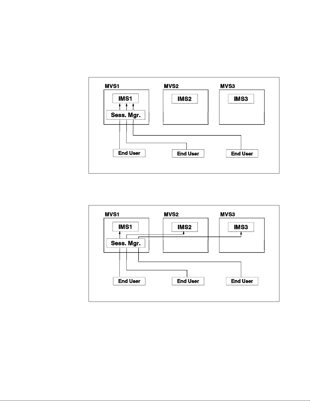
Resolution Exit is not used. In this example, the session manager resides on
MVS1. IMS1 is on MVS1. IMS2 is on MVS2, and IMS3 is on MVS3. An attempt to
log on to IMS from the session manager will always result in a session with
IMS1. This will eliminate any balancing. Without the exit, VTAM will select an
IMS instance on the same node (MVS) with the session manager when one
exists. This is illustrated in Figure 4.
Figure 4. Using One Instance of a Session Manager Without ISTEXCGR
The VTAM generic resources exit (ISTEXCGR) can be used to balance the
sessions. A possible result of the use of this capability is shown in Figure 5.
Figure 5. Using One Instance of a Session Manager With ISTEXCGR
There is another way to balance sessions with IMS when using only one
instance of the session manager. This is to place the session manager on an
MVS which does not contain an IMS instance in the generic resource group.
Since there is no local IMS, the ISTEXCGR exit routine does not have to be used
to balance sessions. The normal VTAM generic resource processes will balance
the sessions. This is illustrated in Figure 6 on page 78.
Chapter 9. IMS TM Workload Balancing Considerations 77
Page 96
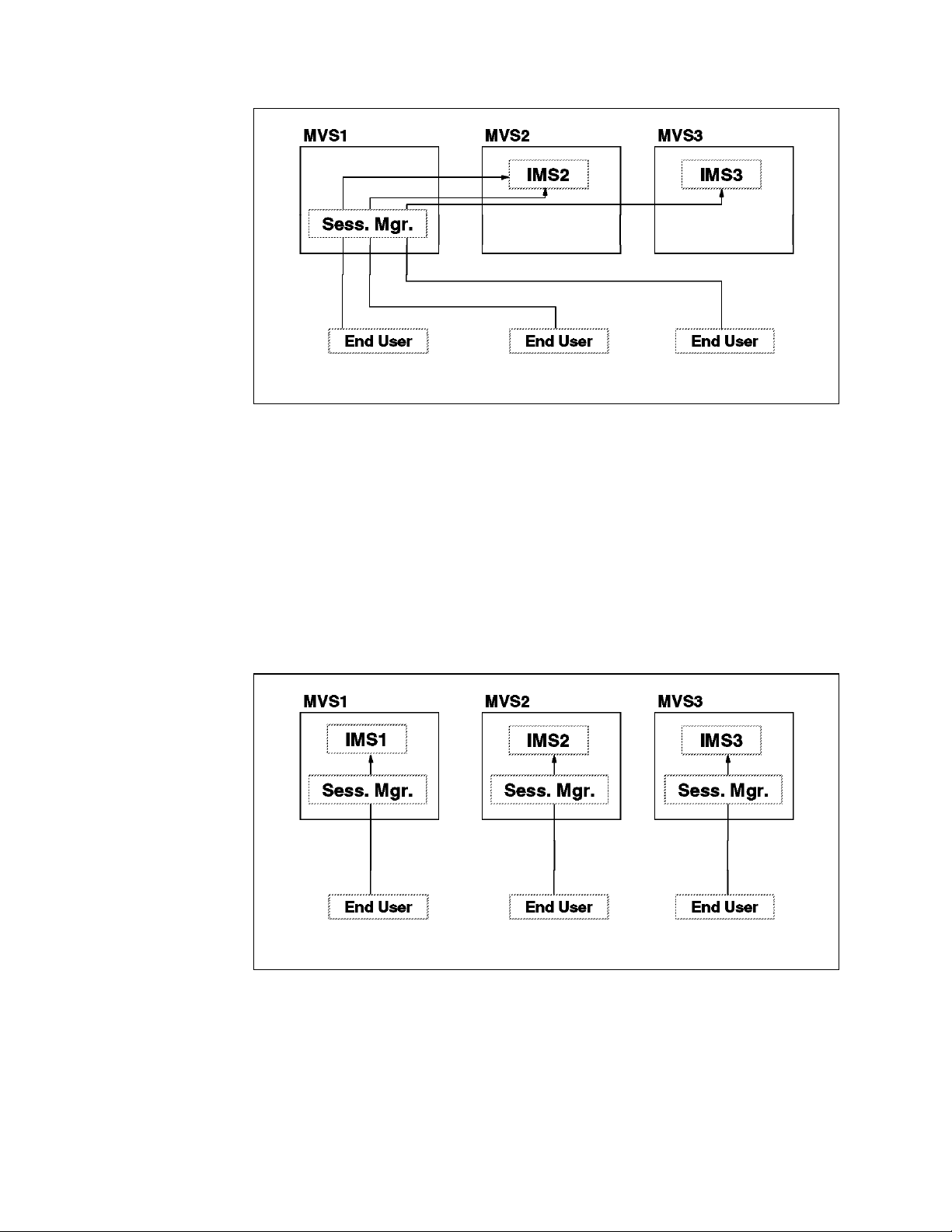
Figure 6. Placing the Session Manager on an MVS Without IMS
9.2.8.2 Using Multiple Instances of the Session Manager
Some installations might want to have multiple instances of their session
manager. This provides availability benefits as well as additional options for
workload balancing.
If the session manager supports generic resources, the logons to the session
manager can be balanced. If each MVS system has both a session manager
instance and an IMS instance, the balancing of the logons across the session
managers allows one to always use the local IMS when establishing sessions
between the session manager and IMS. This is illustrated in Figure 7.
Figure 7. Session Managers With Generic Resource Support
Of course, there are many other possible configurations for sessions managers
and IMS instances.
Some installations will receive the greatest balancing and availability benefits by
using generic resources with both IMS and the session managers. This will tend
to balance the use of session managers and IMS systems, even when they are
not paired on each MVS system.
78 IMS Parallel Sysplex Migration Planning Guide
Page 97
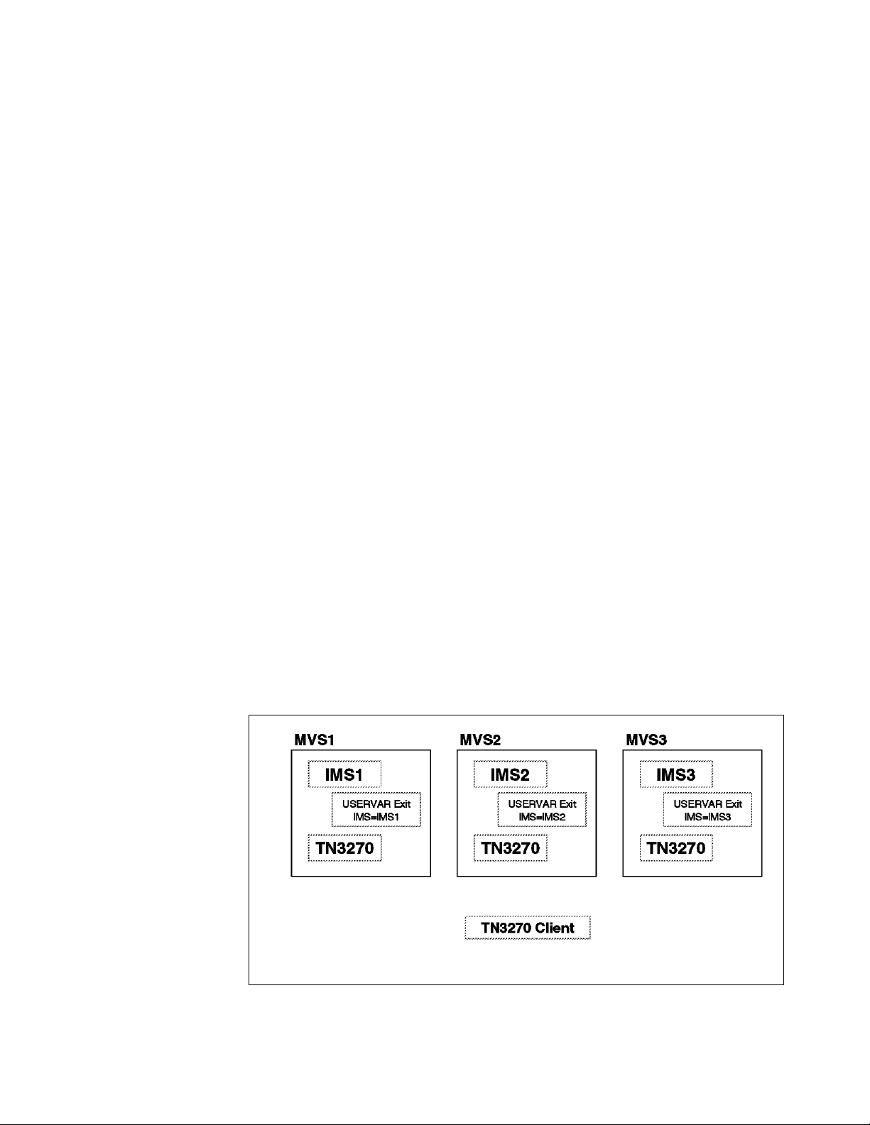
Some session managers do not have generic resource support. Installations
with these session managers give their end-users instructions about which
session managers are available to them. Such installations can use generic
resources with IMS to balance the workload across the IMS systems.
9.2.9 Network Workload Balancing With TCP/IP and TN3270
Users of TCP/IP can take advantage of workload balancing capabilities provided
by Domain Name Server (DNS) in OS/390 Version 2 Release 5 and later
releases. They are also available in Release 4 through a no-charge kit. These
DNS capabilities are appropriate for users with long-term connections, such as
TN3270 users.
DNS allows a user to resolve a name request to one of multiple IP addresses in
a Parallel Sysplex. Each connection request is assigned an actual IP address
based either on a weight assigned to each IP address or on Workload Manager
capacity and workload information. DNS provides functional equivalence with
VTAM generic resources for TCP/IP users, such as TN3270. As is explained
below, TN3270 users can use both DNS and generic resources.
9.2.9.1 DNS Without Generic Resources
The following example illustrates a possible use of this DNS function. Assume
that IMS1 is executing on MVS1, IMS2 on MVS2, and IMS3 on MVS3. Each MVS
system has an instance of TN3270. A TN3270 client logs in to TN3270. DNS
resolves the request to one of the TN3270 instances. This balances TN3270 login
requests across the instances of TN3270 servers. The user then logs on to IMS
establishing a VTAM session between the TN3270 instance and an IMS. If VTAM
generic resources are not used, the user must either log on to a specific IMS or
use a USERVAR exit to select a particular IMS. If the user must choose a
specific IMS instance, DNS does not provide any workload balancing. USERVAR
exits can be used to provide workload balancing. In this scheme, each MVS
would have a different USERVAR exit. Each exit would assign a value equal to
the IMS instance executing on its MVS. This scheme is illustrated in Figure 8. It
shows USERVAR exit routines which always assign an IMS log on request to the
IMS on the same MVS.
Figure 8. Using DNS With TN3270 and VTAM GR
Chapter 9. IMS TM Workload Balancing Considerations 79
Page 98

This scheme could be enhanced to handle IMS failures. If an IMS system fails,
the USERVAR exit routine could be dynamically modified to route new logon
requests to an IMS on another MVS.
9.2.9.2 DNS With Generic Resources
VTAM generic resources can be used in conjunction with TN3270 and DNS. The
following example illustrates a possible use of this combination. It is similar to
the example in Figure 8 on page 79 but USERVAR is not used. Instead, GR is
used. The log on requests to IMS from TN3270 will always result in a session
with the IMS on the same MVS. This occurs because TN3270 and the IMS reside
on the same node. GR will always select a local generic resource if one is
available unless the VTAM generic resources exit (ISTEXCGR) indicates
otherwise. This example is illustrated Figure 9. It shows the TN3270 login
request resulting in a connection to the TN3270 on MVS1. The IMS logon request
results in a connection to IMS1.
Figure 9. Using DNS With TN3270 and VTAM GR
If the IMS on the same MVS with the TN3270 being used is not available, the
VTAM logon request will result in a session with one of the IMS instances on
another MVS. The IMS instance chosen depends on the usual VTAM generic
resources considerations. This example is illustrated by Figure 10 on page 81.
It shows the IMS logon request resulting in a session with IMS2.
80 IMS Parallel Sysplex Migration Planning Guide
Page 99

Figure 10. Using DNS With TN3270 and VTAM GR After a Failure of IMS1
9.3 Application Workload Balancing
Application workload balancing attempts to balance the transaction workload
among the IMS systems in the IMSplex. Depending upon how network balancing
is achieved, your IMSplex configuration (cloned, partitioned, and so on.), and
your workload balancing objectives, application workload balancing may or may
not be an automatic result. If application workload balancing objectives are not
achieved, additional implementation choices must be considered and selected to
ensure the resulting application workload distribution satisfies your objectives.
There are several implementation choices to achieve application workload
balancing, including:
•
Network workload balancing
•
MSC balancing
•
IMS Workload Router
•
Shared Queues
The first three choices are available to users of IMS/ESA Version 5 or 6. The
last choice is only available to users of IMS/ESA Version 6.
9.3.1 Network Workload Balancing
The various techniques to accomplish network workload balancing were
discussed in the previous section, 9.2, “Network Workload Balancing” on
page 66.
If one wished that 50 percent of the application workload would be processed on
IMS1 and 50 percent would be processed on IMS2, one could approximate that
workload distribution by having 50 percent of the end-users log on to IMS1 and
the remaining 50 percent of the end-users log on to IMS2. If this 50/50 split of
the network workload can be achieved, an application workload split of 50/50 is
also a likely result as long as IMS1 and IMS2 are clones of one another.
If systems are partitioned rather than cloned, network load balancing more than
likely will not result in application workload balancing. A partitioned
Chapter 9. IMS TM Workload Balancing Considerations 81
Page 100

configuration by application, for example dictates where application processing
will take place.
9.3.2 MSC Balancing
MSC balancing attempts to balance the workload among the IMS systems in the
IMSplex by routing work to the various systems through MSC definitions and/or
MSC exits. For example, one could have all of the end-users logged on to one of
the IMS systems and have that system route some percentage of the
transactions to another system or systems within the IMSplex. Let us assume,
for example, that all of the end-users are logged on to IMS1. In addition, we
want 40 percent of the transaction workload to process on IMS1 and the other 60
percent to process on IMS2. Given these assumptions, we would want IMS1 to
route 60 percent of the transaction workload to IMS2.
This routing could either be based on specific transaction codes (transaction
codes A through G process on IMS1 and transaction codes H - Z process on
IMS2), or could be based on percentages (40 percent of transaction codes A - Z
process on IMS1 and 60 percent of transaction codes A - Z process on IMS2).
Routing based on specific transaction codes (is a possible solution when
systems are partitioned by application) can be accomplished through the use of
SYSGEN specifications. Routing based on percentages (is a possible solution
when systems are cloned) requires the use of the MSC Input Message Routing
Exit (DFSNPRT0), introduced in IMS/ESA Version 5.
The MSC Input Message Routing Exit, DFSNPRT0, has the capability to route
transactions to a specific IMS system based on either MSNAME or SYSID. Thus,
if one wanted 60 percent of all transactions entered on IMS1 (that′s where all the
end-users are connected) to be routed to IMS2, one could write a DFSNPRT0
routine that would issue a STCK, divide the result by 100, and route the
transaction to IMS2 if the remainder were 0 - 59.
9.3.3 IMS Workload Router
The easiest way to implement MSC balancing is through the IMS/ESA Workload
Router for MVS (WLR), a separate product (5697-074).
The IMS Workload Router works with IMS TM to route or balance the IMS
transaction workload across multiple IMS systems in a Sysplex or non-Sysplex
environment. WLR provides flexibility in how the workload is routed and also
allows routing to be changed dynamically.
WLR software is integrated with the IMS TM software and provides transaction
workload balancing that is completely transparent to end-users and IMS
applications.
WLR superimposes the roles of router (front-end) and server (back-end) systems
on IMS systems in the WLR configuration. Routers route the transaction work
load to servers; servers process the transactions and return any responses to
the router. WLR supports a configuration of one or more router systems coupled
with one or more server systems. This makes WLR adaptable to a wide variety
of Parallel Sysplex configurations.
The use of WLR within a Parallel Sysplex data sharing environment to distribute
application workload is inappropriate when shared queues are used. With
shared queues, MSC links can be defined among the members of a shared
82 IMS Parallel Sysplex Migration Planning Guide
 Loading...