

Page 1

RS/6000 Enterprise Server Model H Series IBM
User's Guide
SA38-0546-01
Page 2

Second Edition (April 1999)
The following paragraph does not apply to the United Kingdom or any country where
such provisions are inconsistent with local law: THIS PUBLICATION IS PROVIDED “AS
IS” WITHOUT WARRANTY OF ANY KIND, EITHER EXPRESS OR IMPLIED, INCLUDING,
BUT NOT LIMITED TO, THE IMPLIED WARRANTIES OF MERCHANTABILITY OR FITNESS
FOR A PARTICULAR PURPOSE. Some states do not allow disclaimer of express or implied
warranties in certain transactions, therefore, this statement may not apply to you.
This publication could include technical inaccuracies or typographical errors. Changes are
periodically made to the information herein; these changes will be incorporated in new editions
of the publication. The manufacturer may make improvements and/or changes in the
product(s) and/or the program(s) described in this publication at any time, without notice.
It is possible that this publication may contain reference to, or information about, products
(machines and programs), programming, or services that are not announced in your country.
Such references or information must not be construed to mean that these products, programming, or services will be announced in your country. Any reference to a specific licensed
program in this publication is not intended to state or imply that you can use only that licensed
program. You can use any functionally equivalent program instead.
Requests for technical information about products should be made to your authorized reseller
or marketing representative.
International Business Machines Corporation 1998, 1999. All rights reserved.
Note to U.S. Government Users -- Documentation related to restricted rights -- Use, duplication or disclosure is subject to restrictions set forth is GSA ADP Schedule Contract with IBM
Corp.
Page 3

Contents
Communications Statements . . . . . . . . . . . . . . . . . . . . . . . . . . . . . vii
Federal Communications Commission (FCC) Statement .............. vii
European Union (EU) Statement ............................ vii
International Electrotechnical Commission (IEC) Statement ............ viii
United Kingdom Telecommunications Safety Requirements ............ viii
Avis de conformité aux normes du ministère des Communications du Canada . viii
Canadian Department of Communications Compliance Statement ........ viii
VCCI Statement . . . . . . . . . . . . . . . . . . . . . . . . . . . . . . . . . . . . . ix
Electromagnetic Interference (EMI) Statement - Taiwan .............. ix
Radio Protection for Germany .............................. x
Safety Notices . . . . . . . . . . . . . . . . . . . . . . . . . . . . . . . . . . . . . . xi
Electrical Safety . . . . . . . . . . . . . . . . . . . . . . . . . . . . . . . . . . . . . xi
Laser Safety Information ................................ xiii
Environmental Notices . . . . . . . . . . . . . . . . . . . . . . . . . . . . . . . . . xv
Product Recycling and Disposal ............................ xv
Battery Return Program ................................. xv
Environmental Design . . . . . . . . . . . . . . . . . . . . . . . . . . . . . . . . . . xv
About This Book .................................... xvii
ISO 9000 . . . . . . . . . . . . . . . . . . . . . . . . . . . . . . . . . . . . . . . . . xvii
Related Publications . . . . . . . . . . . . . . . . . . . . . . . . . . . . . . . . . . . xvii
Trademarks . . . . . . . . . . . . . . . . . . . . . . . . . . . . . . . . . . . . . . . xviii
Chapter 1. System Description . . . . . . . . . . . . . . . . . . . . . . . . . . . 1-1
Chapter 2. Using the System Unit ......................... 2-1
Ergonomic Information . . . . . . . . . . . . . . . . . . . . . . . . . . . . . . . . . . 2-1
Starting the System Unit ................................. 2-1
Stopping the System Unit ................................ 2-3
Reading the Operator Panel Display .......................... 2-4
Using the Keyboards ................................... 2-5
Using the Three-Button Mouse ............................. 2-7
Using the 3.5-Inch Diskette Drive .......................... 2-11
Using the CD-ROM Drive ............................... 2-13
Using the Hot Swap Disk Drives ........................... 2-16
Chapter 3. Service Processor Menus ....................... 3-1
Service Processor Menus ................................ 3-3
General User Menus ................................... 3-4
Preface iii
Page 4

Privileged User Menus .................................. 3-6
Service Processor Functions and Features ..................... 3-23
Chapter 4. System Management Services ..................... 4-1
Graphical System Management Services ....................... 4-1
Config . . . . . . . . . . . . . . . . . . . . . . . . . . . . . . . . . . . . . . . . . . . 4-4
MultiBoot . . . . . . . . . . . . . . . . . . . . . . . . . . . . . . . . . . . . . . . . . . 4-6
Utilities . . . . . . . . . . . . . . . . . . . . . . . . . . . . . . . . . . . . . . . . . . 4-10
Password . . . . . . . . . . . . . . . . . . . . . . . . . . . . . . . . . . . . . . . . 4-11
Hard Disk Spin Up Delay ............................... 4-15
Error Log . . . . . . . . . . . . . . . . . . . . . . . . . . . . . . . . . . . . . . . . 4-16
RIPL . . . . . . . . . . . . . . . . . . . . . . . . . . . . . . . . . . . . . . . . . . . 4-17
SCSI ID . . . . . . . . . . . . . . . . . . . . . . . . . . . . . . . . . . . . . . . . . 4-21
Update . . . . . . . . . . . . . . . . . . . . . . . . . . . . . . . . . . . . . . . . . . 4-22
Text-Based System Management Services ..................... 4-24
Open Firmware Command Prompt .......................... 4-38
Chapter 5. Installing Options . . . . . . . . . . . . . . . . . . . . . . . . . . . . 5-1
Safety Considerations . . . . . . . . . . . . . . . . . . . . . . . . . . . . . . . . . . 5-2
Handling Static-Sensitive Devices ........................... 5-3
Expansion Bays . . . . . . . . . . . . . . . . . . . . . . . . . . . . . . . . . . . . . 5-4
Installing Disk Drives into the Hot-Swap Bays .................... 5-6
Removing Disk Drives from the Hot-Swap Bays .................. 5-12
Chapter 6. Using the Online and Standalone Diagnostics ........... 6-1
Diagnostic Sources . . . . . . . . . . . . . . . . . . . . . . . . . . . . . . . . . . . . 6-1
Standalone and Online Diagnostics Operating Considerations ........... 6-1
Online Diagnostics Modes of Operation ........................ 6-9
Standalone Diagnostic Operation .......................... 6-12
Location Codes . . . . . . . . . . . . . . . . . . . . . . . . . . . . . . . . . . . . . 6-13
Physical Location Codes ............................... 6-13
AIX Location Codes .................................. 6-14
AIX and Physical Location Code Reference Table Model 50 ........... 6-18
AIX and Physical Location Code Reference Table Model 70 ........... 6-25
Chapter 7. Using the Service Aids ......................... 7-1
Introduction to Service Aids ............................... 7-3
AIX Shell Prompt Service Aid .............................. 7-4
Backup/Restore Media Service Aid .......................... 7-4
Configure Remote Maintenance Policy Service Aid ................. 7-4
Configure Ring Indicate Power On Policy Service Aid ................ 7-6
Configure Surveillance Policy Service Aid ...................... 7-7
Configure Reboot Policy Service Aid ......................... 7-7
Save or Restore Hardware Management Policies Service Aid ........... 7-9
iv RS/6000 Enterprise Server Model H Series User's Guide
Page 5

Diagnostic Package Utility Service Aid ........................ 7-9
Dials and LPFK Configuration Service Aid ..................... 7-10
Disk Based Diagnostic Update Service Aid and Update Disk Based Diagnostic
Task . . . . . . . . . . . . . . . . . . . . . . . . . . . . . . . . . . . . . . . . . . 7-10
Disk Media Service Aids ................................ 7-10
Disk Maintenance Service Aid ............................ 7-12
Diskette Media Service Aid .............................. 7-13
Display or Change Configuration or Vital Product Data (VPD) Service Aid ... 7-14
Display and Change Diagnostic Test List Service Aid ............... 7-16
Display Previous Diagnostic Results Service Aid ................. 7-16
Display Test Patterns Service Aid .......................... 7-17
Enhanced SCSI Display Configuration Service Aid ................ 7-17
Generic Microcode Download Service Aid ..................... 7-17
Hardware Error Report Service Aid and Display Hardware Error Log Task .. 7-18
ISA Adapter Configuration Service Aid ....................... 7-18
Machine Check Error Log Service Aid ........................ 7-18
Microcode Download Service Aid .......................... 7-19
Periodic Diagnostics Service Aid ........................... 7-19
SCSI Bus Analyzer Task ............................... 7-19
SCSI Tape Utilities Service Aid ............................ 7-21
Service Hints Service Aid ............................... 7-21
Update System or Service Processor Flash Service Aid ............. 7-22
Display Firmware Device Node ............................ 7-22
Display Resource Attributes .............................. 7-22
7135 RAIDant Array Service Aid ........................... 7-23
PCI RAID Physical Disk Identify ........................... 7-23
SSA Location Code Format .............................. 7-24
SSA Loops and Links ................................. 7-25
SSA Service Aids .................................... 7-30
Service Aid Error Codes ................................ 7-47
Using the Service Aids for SSA-Link Problem Determination ........... 7-48
Finding the Physical Location of a Device ..................... 7-54
Microcode Maintenance . . . . . . . . . . . . . . . . . . . . . . . . . . . . . . . . 7-55
Vital Product Data (VPD) ............................... 7-56
Chapter 8. Using the System Verification Procedure .............. 8-1
Step 1. Considerations before Running This Procedure .............. 8-1
Step 2. Loading the Diagnostics ............................ 8-2
Step 3. Running System Verification .......................... 8-3
Step 4. Additional System Verification ......................... 8-3
Step 5. Stopping the Diagnostics ............................ 8-4
Chapter 9. Hardware Problem Determination ................... 9-1
Problem Determination Using the Standalone or Online Diagnostics ....... 9-1
Preface v
Page 6

Problem Determination When Unable to Load Diagnostics ............ 9-10
Chapter 10. SSA Problem Determination Procedures ............ 10-1
Disk Drive Module Power-On Self-Tests (POSTs) ................. 10-1
Adapter Power-On Self-Tests (POSTs) ....................... 10-2
Appendix A. System Records . . . . . . . . . . . . . . . . . . . . . . . . . . . A-1
Record the Identification Numbers .......................... A-1
Device Records . . . . . . . . . . . . . . . . . . . . . . . . . . . . . . . . . . . . . A-2
Appendix B. Service Processor Setup and Test ................ B-1
Testing the Setup .................................... B-2
Appendix C. Modem Configurations . . . . . . . . . . . . . . . . . . . . . . . C-1
Sample Modem Configuration Files ......................... C-1
Configuration File Selection .............................. C-2
Seamless Transfer of a Modem Session ...................... C-6
Modem Configuration Samples ............................ C-9
Appendix D. Service Processor Operational Phases ............. D-1
Index . . . . . . . . . . . . . . . . . . . . . . . . . . . . . . . . . . . . . . . . . . . X-1
Reader's Comments — We'd Like to Hear From You ............. X-3
vi RS/6000 Enterprise Server Model H Series User's Guide
Page 7

Communications Statements
The following statement applies to this product. The statement for other products
intended for use with this product appears in their accompanying documentation.
Federal Communications Commission (FCC) Statement
Note: This equipment has been tested and found to comply with the limits for a
Class A digital device, pursuant to Part 15 of the FCC Rules. These limits are
designed to provide reasonable protection against harmful interference when the
equipment is operated in a commercial environment. This equipment generates,
uses, and can radiate radio frequency energy and, if not installed and used in
accordance with the instruction manual, may cause harmful interference to radio
communications. Operation of this equipment in a residential area is likely to cause
harmful interference in which case the user will be required to correct the interference at his own expense.
Properly shielded and grounded cables and connectors must be used in order to
meet FCC emission limits. Neither the provider nor the manufacturer are responsible
for any radio or television interference caused by using other than recommended
cables and connectors or by unauthorized changes or modifications to this equipment. Unauthorized changes or modifications could void the user's authority to
operate the equipment.
This device complies with Part 15 of the FCC Rules. Operation is subject to the
following two conditions: (1) this device may not cause harmful interference, and (2)
this device must accept any interference received, including interference that may
cause undesired operation.
European Union (EU) Statement
This product is in conformity with the protection requirements of EU Council Directive
89/336/EEC on the approximation of the laws of the Member States relating to
electromagnetic compatibility. The manufacturer cannot accept responsibility for any
failure to satisfy the protection requirements resulting from a non-recommended modification of the product, including the fitting of option cards supplied by third parties.
Consult with your dealer or sales representative for details on your specific hardware.
This product has been tested and found to comply with the limits for Class A Information Technology Equipment according to CISPR 22 / European Standard EN
55022. The limits for Class A equipment were derived for commercial and industrial
environments to provide reasonable protection against interference with licensed
communication equipment.
Communications Statements vii
Page 8

Attention: This is a Class A product. In a domestic environment this product may
cause radio interference in which case the user may be required to take adequate
measures.
International Electrotechnical Commission (IEC) Statement
This product has been designed and built to comply with IEC Standard 950.
United Kingdom Telecommunications Safety Requirements
This equipment is manufactured to the International Safety Standard EN60950 and
as such is approved in the UK under the General Approval Number
NS/G/1234/J/100003 for indirect connection to the public telecommunication network.
The network adapter interfaces housed within this equipment are approved separately, each one having its own independent approval number. These interface
adapters, supplied by the manufacturer, do not use or contain excessive voltages.
An excessive voltage is one which exceeds 70.7 V peak ac or 120 V dc. They interface with this equipment using Safe Extra Low Voltages only. In order to maintain
the separate (independent) approval of the manufacturer's adapters, it is essential
that other optional cards, not supplied by the manufacturer, do not use main voltages
or any other excessive voltages. Seek advice from a competent engineer before
installing other adapters not supplied by the manufacturer.
Avis de conformité aux normes du ministère des Communications du
Canada
Cet appareil numérique de la classe A respecte toutes les exigences du Réglement
sur le matériel brouilleur du Canada.
Canadian Department of Communications Compliance Statement
This Class A digital apparatus meets the requirements of the Canadian
Interference–Causing Equipment Regulations.
viii RS/6000 Enterprise Server Model H Series User's Guide
Page 9
VCCI Statement
The following is a summary of the VCCI Japanese statement in the box above.
This is a Class A product based on the standard of the Voluntary Control Council for
Interference by Information Technology Equipment (VCCI). If this equipment is used
in a domestic environment, radio disturbance may arise. When such trouble occurs,
the user may be required to take corrective actions.
Electromagnetic Interference (EMI) Statement - Taiwan
The following is a summary of the EMI Taiwan statement above.
Warning: This is a Class A product. In a domestic environment this product may
cause radio interference in which case the user will be required to take adequate
measures.
Communications Statements ix
Page 10

Radio Protection for Germany
Dieses Gerät ist berechtigt in Übereinstimmung mit Dem deutschen EMVG vom
9.Nov.92 das EG–Konformitätszeichen zu führen.
Der Aussteller der Konformitätserklärung ist die IBM Germany.
Dieses Gerät erfüllt die Bedingungen der EN 55022 Klasse A. Für diese von
Geräten gilt folgende Bestimmung nach dem EMVG:
Geräte dürfen an Orten, für die sie nicht ausreichend entstört sind, nur mit
besonderer Genehmigung des Bundesministers für Post und Telekommunikation
oder des Bundesamtes für Post und Telekommunikation betrieben werden. Die
Genehmigung wird erteilt, wenn keine elektromagnetischen Störungen zu erwarten
sind.
(Auszug aus dem EMVG vom 9.Nov.92, Para.3, Abs.4)
Hinweis
Dieses Genehmigungsverfahren ist von der Deutschen Bundespost noch nicht
veröffentlicht worden.
x RS/6000 Enterprise Server Model H Series User's Guide
Page 11

Safety Notices
A
danger
death or serious personal injury.
A
caution
moderate or minor personal injury.
Electrical Safety
Observe the following safety instructions any time you are connecting or disconnecting devices attached to the workstation.
DANGER
notice indicates the presence of a hazard that has the potential of causing
notice indicates the presence of a hazard that has the potential of causing
An electrical outlet that is not correctly wired could place hazardous
voltage on metal parts of the system or the devices that attach to the
system. It is the responsibility of the customer to ensure that the outlet
is correctly wired and grounded to prevent an electrical shock.
Before installing or removing signal cables, ensure that the power
cables for the system unit and all attached devices are unplugged.
When adding or removing any additional devices to or from the system,
ensure that the power cables for those devices are unplugged before
the signal cables are connected. If possible, disconnect all power
cables from the existing system before you add a device.
Use one hand, when possible, to connect or disconnect signal cables
to prevent a possible shock from touching two surfaces with different
electrical potentials.
During an electrical storm, do not connect cables for display stations,
printers, telephones, or station protectors for communication lines.
CAUTION:
This product is equipped with a three–wire power cable and plug for the user's
safety. Use this power cable with a properly grounded electrical outlet to avoid
electrical shock.
Preface xi
Page 12

DANGER
To prevent electrical shock hazard, disconnect the power cable from
the electrical outlet before relocating the system.
CAUTION:
This unit has more than one power supply cord. To reduce the risk of electrical shock, disconnect two power supply cords before servicing.
xii RS/6000 Enterprise Server Model H Series User's Guide
Page 13
Laser Safety Information
The optical drive in this system unit is a laser product. The optical drive has a label
that identifies its classification. The label, located on the drive, is shown below.
CLASS 1 LASER PRODUCT
LASER KLASSE 1
LUOKAN 1 LASERLAITE
APPAREIL A LASERDE CLASSE1
IEC 825:1984 CENELEC EN 60 825:1991
The optical drive in this system unit is certified in the U.S. to conform to the requirements of the Department of Health and Human Services 21 Code of Federal Regulations (DHHS 21 CFR) Subchapter J for Class 1 laser products. Elsewhere, the
drive is certified to conform to the requirements of the International Electrotechnical
Commission (IEC) 825 (1st edition 1984) and CENELEC EN 60 825:1991 for Class 1
laser products.
CAUTION:
A class 3 laser is contained in the device. Do not attempt to operate the drive
while it is disassembled. Do not attempt to open the covers of the drive as it
is not serviceable and is to be replaced as a unit.
Class 1 laser products are not considered to be hazardous. The optical drive contains internally a Class 3B gallium-arsenide laser that is nominally 30 milliwatts at
830 nanometers. The design incorporates a combination of enclosures, electronics,
and redundant interlocks such that there is no exposure to laser radiation above a
Class 1 level during normal operation, user maintenance, or servicing conditions.
Preface xiii
Page 14

xiv RS/6000 Enterprise Server Model H Series User's Guide
Page 15

Environmental Notices
Product Recycling and Disposal
Components of the system unit, such as structural parts and circuit cards, can be
recycled where recycling facilities exist. Companies are available to disassemble,
reutilize, recycle, or dispose of electronic products. Contact your account representative for more information. This system unit contains batteries and circuit boards
with lead solder. Before you dispose of this unit, these batteries and circuit boards
must be removed and discarded according to local regulations or recycled where
facilities exist. This book contains specific information on each battery type where
applicable.
Battery Return Program
In the United States, IBM has established a collection process for reuse, recycling, or
proper disposal of used IBM batteries and battery packs. For information on proper
disposal of the batteries in this unit, please contact IBM at 1-800-426-4333. Please
have the IBM part number that is listed on the battery available when you make your
call. For information on battery disposal outside the United States, contact your local
waste disposal facility.
Environmental Design
The environmental efforts that have gone into the design of this system signifies
IBM's commitment to improve the quality of its products and processes. Some of
these accomplishments include the elimination of the use of Class I ozone-depleting
chemicals in the manufacturing process and reductions in manufacturing wastes.
For more information, contact an IBM account representative.
Environmental Notices xv
Page 16

xvi RS/6000 Enterprise Server Model H Series User's Guide
Page 17

About This Book
This book provides information on how to install and remove options, use the
system, use diagnostics, use service aids, and verify system operation. This book
also provides information to help you solve some of the simpler problems that might
occur.
ISO 9000
ISO 9000 registered quality systems were used in the development and manufacturing of this product.
Related Publications
The following publications are available:
The
The
The
The
The
The
The
RS/6000 Enterprise Server Model H Series Installation and Service Guide
contains installation instructions, reference information, maintenance analysis
procedures (MAPs), error codes, removal and replacement procedures, and a
parts catalog.
7015 Model R00 Rack Installation and Service Guide
regarding the 7015 Model R00 Rack, which the RS/6000 Enterprise Server
Model H Series may be installed in.
7014 Model S00 Rack Installation and Service Guide
regarding the 7014 Model S00 Rack, which the RS/6000 Enterprise Server
Model H Series may be installed in.
RS/6000 Diagnostic Information for Multiple Bus Systems
nostic information, service request numbers (SRNs), and failing function codes
(FFCs).
contains information
contains information
contains diag-
RS/6000 Adapters, Devices, and Cable Information for Multiple Bus Systems
contains information about adapters, devices, and cables for your system. This
manual is intended to supplement the service information found in the
Diagnostic Information for Multiple Bus Systems
PCI Adapter Placement Reference
restrictions for adapters that can be used in this system.
contains information regarding slot
Site and Hardware Planning Information
plan your installation.
.
contains information to help you
RS/6000
Preface xvii
Page 18

Trademarks
AIX is a registered trademark of the International Business Machines Corpo-
ration.
PowerPC is a trademark of the International Business Machines Corporation.
Velcro is a trademark of Velcro Industries.
xviii RS/6000 Enterprise Server Model H Series User's Guide
Page 19

Chapter 1. System Description
Thank you for selecting a RS/6000 Enterprise Server Model H Series!
The RS/6000 Enterprise Server Model H Series combines PowerPC performance
and system expandability, ensuring that your system adapts to handle ever-changing
operating requirements. The system is specifically designed to support the demands
of network environments.
The RS/6000 Enterprise Server Model H Series incorporates the new, advanced
peripheral component interconnect (PCI) bus, which is faster than the industry
standard architecture (ISA) bus. The Model 50 system also offers ISA as an additional bus architecture, to accommodate businesses that already have invested in
ISA and ISA-based devices.
This book helps you use the system, install and remove some options, configure the
system, and use the system programs that are provided. This book also provides
information to help you solve some of the simpler problems that might occur, and
how to obtain assistance and service. Appendix A on page A-1 provides a section
for you to record all the important information about your system.
The minimum configuration of the RS/6000 Enterprise Server Model H Series
includes:
One PowerPC processor
128MB system memory
One 4.5GB disk drive
One 1.44MB diskette drive
One CD-ROM drive
One unused media bay
One power supply
Chapter 1. System Description 1-1
Page 20

The maximum configuration of the RS/6000 Enterprise Server Model H Series can
include:
Four PowerPC processors
8GB system memory
Twelve 9.1GB internal hot-swappable disk drives
One 1.44MB diskette drive
One CD-ROM drive
One additional media device (may be a tape drive, CD-ROM drive, or a
non-hot-swappable disk drive).
Two power supplies (which provide redundant power).
Two backplanes that can accept up to twelve hot-swappable disk drives (may be
either SCSI or SSA)
1-2 RS/6000 Enterprise Server Model H Series User's Guide
Page 21
Chapter 2. Using the System Unit
Ergonomic Information
Once you have setup your system, we encourage you to visit the Healthy Computing
web site. Good ergonomic practice is important to get the most from your workstation and to avoid discomfort. This means that the equipment and the workplace
should be arranged to suit your individual needs and the kind of work you do.
This web site gives ergonomic guidelines to help you understand the ergonomic considerations that you should know when working at a computer workstation. The
address is:
http://www.us.pc.ibm.com/healthycomputing
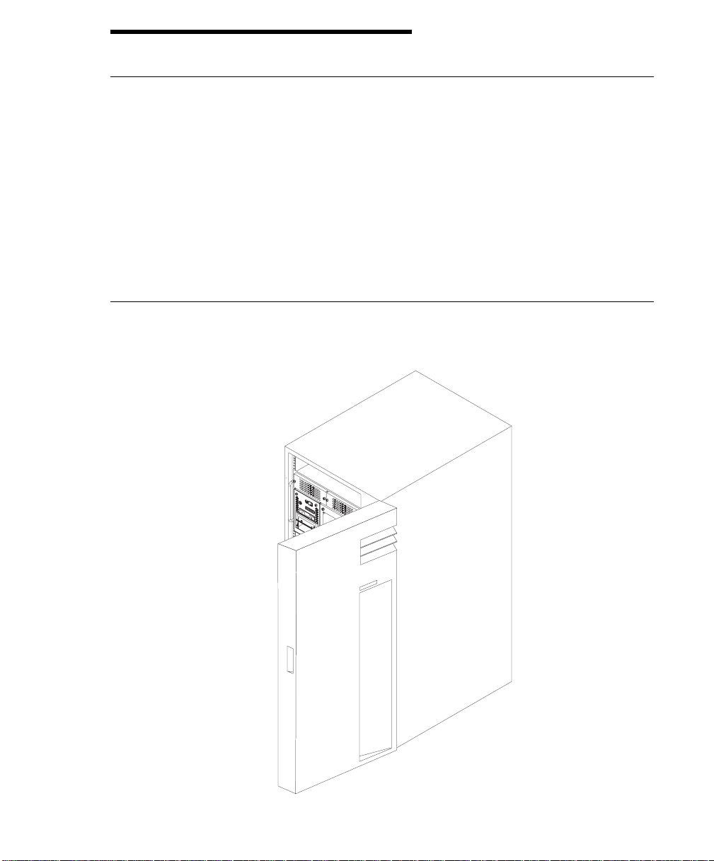
Starting the System Unit
1. Open the front door of the 7014 Model S00 Rack
Chapter 2. Using the System Unit 2-1
Page 22
2. Set the power switches of the attached devices to On.
Note: When the system is plugged in but not powered on, the Power On LED
flashes slowly.
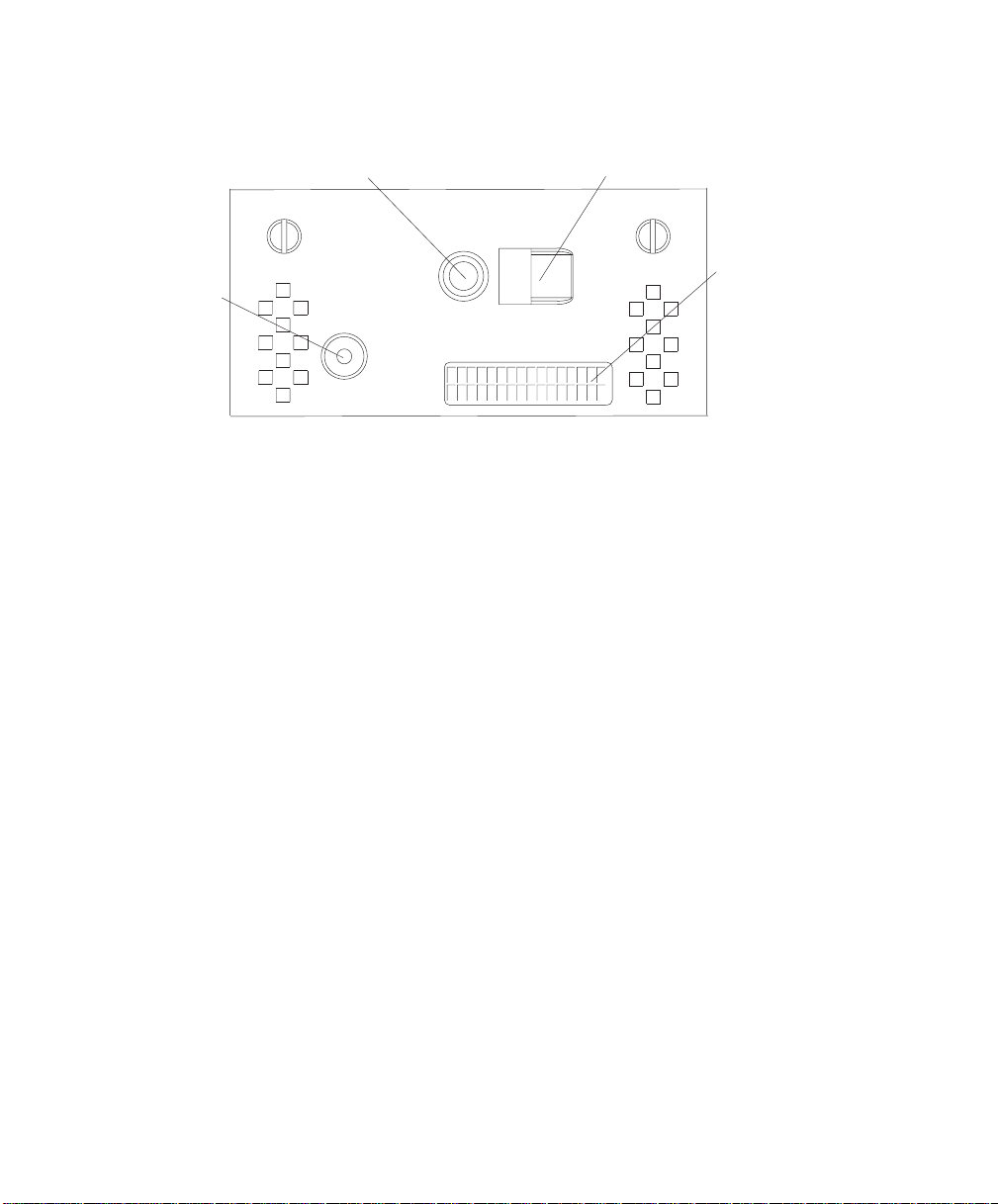
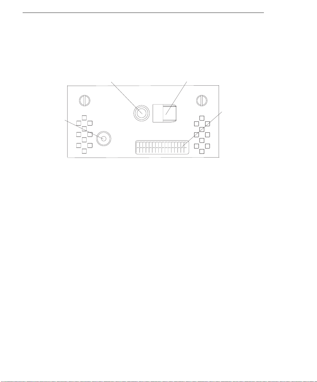
3. Press the Power On button.
1
4
1 Reset Button 3 Operator Panel Display
2 Power On Button 4 Power On LED
2
3
When you press the Power On button, the Power On LED displays a steady
green light, and the system starts a POST (power on self test).
During POST, progress codes appear in the operator panel display.
4. If the Power On LED does not come on and there is no indication of power when
you press the Power On button, ensure that the power cord, located at the back
of the system unit, is plugged into a grounded electrical outlet. If this does not
solve the problem, go to Chapter 9 on page 9-1. If the LED is not flashing and
OK is not displayed in the operator panel display, go to Chapter 6 on page 6-1.
For a more complete discussion of power on methods, see “System Power-On
Methods” on page 3-25.
2-2 RS/6000 Enterprise Server Model H Series User's Guide
Page 23

Stopping the System Unit
Attention: When using the shutdown procedure for your system, enter the correct
command before you stop the system unit. Failure to do so may result in the loss of
data. If you need information on the shutdown procedure for your operating system,
see your operating system documentation.
1. Before stopping the system unit, you must first perform a shutdown procedure of
the operating system to prevent the loss of data.
2. After you shut down the operating system, set the power switches of the
attached devices to Off.
3. The system unit is powered down by the shut down procedure.
Chapter 2. Using the System Unit 2-3
Page 24
Reading the Operator Panel Display
The operator panel display is used to:
Track the progress of the system unit self tests and configuration program.
Display codes when the operating system comes to an abnormal end.
Display system messages.
1
4
1 Reset Button 3 Operator Panel Display
2 Power On Button 4 Power On LED
During power on self test (POST), four characters display indicating the progress of
the testing. If an error is detected that requires attention, the system unit halts and
an eight digit number displays in the operator panel display to identify the error.
2
3
2-4 RS/6000 Enterprise Server Model H Series User's Guide
Page 25
Using the Keyboards
There are several keyboards available for the system unit. The keyboards have
various keys that enter data and control the cursor location. The keyboards can be
engraved for the languages of different countries.
The functions of each keyboard depends on the software used. The character sets
for the keyboards are contained and explained in the information for your operating
system.
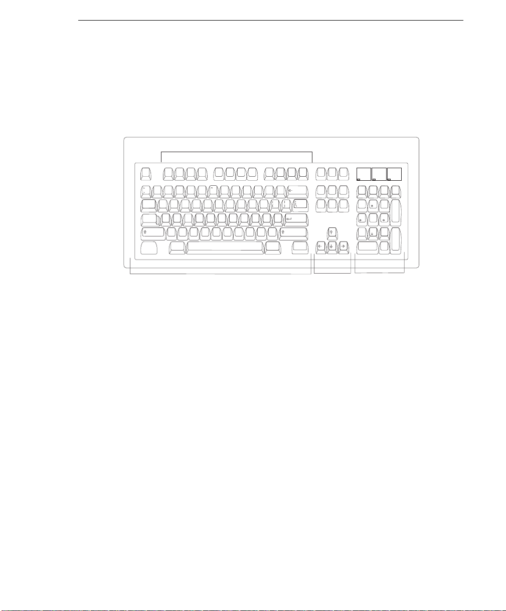
Function Keys
Num
Caps
Print
Esc F1 F2 F3 F4 F6 F7 F8F5 F9 F10 F11 F12 Pause
@
#
!
123
Tab
Caps
Lock
Shift
Ctrl Alt
$% &
4567
QWER YUIT OP
ASDFGHJKL :
ZXCVBNM
*
8
()
90
<
>
,
_
+
-
=
"
,
;
?
Shift
/.
Alt Ctrl
Backspace
Enter
Scroll
Screen
Lock
SysRq
Insert
Home
Delete
End
Lock
Break
Page
Up
Page
Down
Lock
Num
/*-
Lock
789
Home PgUp
654
321
End
PgDn
.
0
Ins Del
Scroll
Lock
+
Enter
Typewriter Keys
Control
Keys
Numeric
Keypad
The keyboard is divided into four sections:
Function keys are multipurpose keys and their function is controlled by the oper-
ating system.
Typewriter keys are similar to a standard typewriter. Their function is controlled
by the software.
Control keys move the cursor on the screen and do programmed control func-
tions. The movement and functions depend on the application used.
Numeric keypad is arranged like a calculator to help when typing numbers.
Chapter 2. Using the System Unit 2-5
Page 26
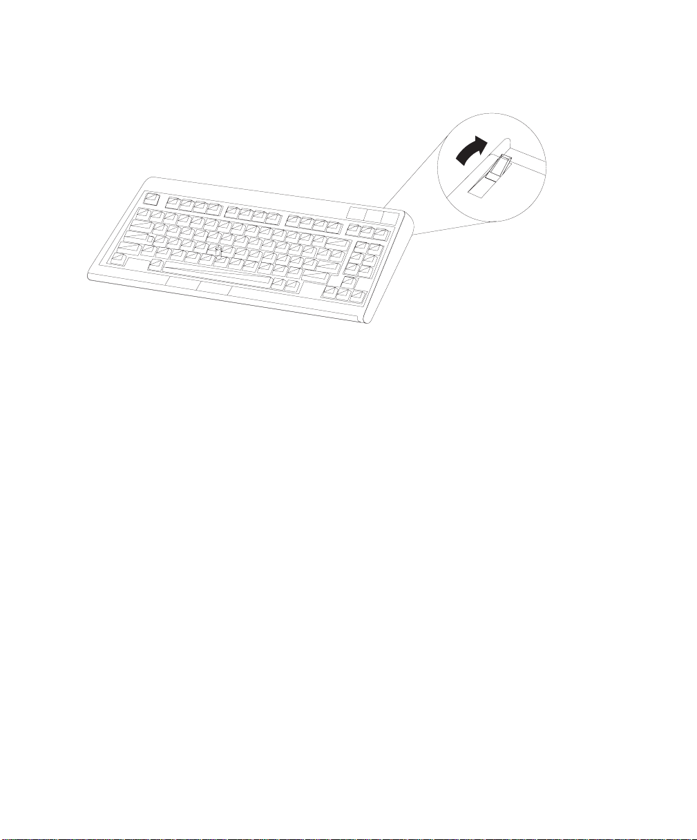
All of the keyboards adjust for typing comfort. To tilt the keyboard, pull out the keyboard legs. The legs snap into position. To decrease the tilt of the keyboard, rotate
the keyboard legs until they snap into the bottom of the keyboard case.
The keyboard cable plugs into the keyboard connector at the rear of the system unit.
2-6 RS/6000 Enterprise Server Model H Series User's Guide
Page 27

Using the Three-Button Mouse
The mouse is a hand-operated locating device. A three-button mouse is available for
use with the system unit.
Consult your application publication for the exact use of the three-button mouse.
You can use the mouse to perform such functions as positioning a cursor, selecting
items from a menu, or moving around in your document much easier and faster than
if you used only the keyboard. The cursor moves exactly as you move the mouse on
a flat surface, such as a desktop.
When you move the mouse around on a flat surface, as shown in this illustration, the
cursor moves on the display screen; the movement changes the position of the
cursor.
Chapter 2. Using the System Unit 2-7
Page 28

With the mouse buttons, you can perform functions such as selecting and deselecting options, extending your selection, or choosing a command. The precise function of your mouse depends on the software you are using.
The mouse has a cable that plugs into the mouse connector at the rear of the
system unit.
Handling the Mouse Correctly
For best operation, handle the mouse with care. Incorrect handling can damage the
mouse.
Do not:
Operate the mouse on cloth, unfinished wood, newspaper, or carpet
Drop or hit the mouse
Carry the mouse by holding onto the cable
Expose the mouse to extreme temperatures or direct sunlight
Place the mouse in liquid spills
2-8 RS/6000 Enterprise Server Model H Series User's Guide
Page 29

Caring for the Mouse
The operating surface for the mouse should be smooth, clean, and flat. For
example, you can operate the mouse on the following surfaces:
Finished wood
Glass
Enamel
Plastic
Paper (except newspaper)
Metal
Rough surfaces collect contaminants that can be transferred to the interior of the
mouse by the ball. The surface you use should be free from spills, dirt, dust, lint,
wax, eraser dust, and other foreign matter. Rough surfaces can also cause the pads
located on the bottom of the mouse to prematurely wear. A deeply pitted surface
could cause erratic operation of the mouse.
Inspect the work surface for spills or other contaminants.
Dust the work surface.
If you are using a paper pad, inspect it for wear and replace it if necessary.
Chapter 2. Using the System Unit 2-9
Page 30

Cleaning the Mouse
1. Remove the retaining ring by turning it counterclockwise, in the direction of the
arrow as shown in the illustration.
Retaining Ring
Ball
Cavity
2. Remove the ball.
3. Inspect the ball for contaminants. Wipe it clean with a dry, lint-free cloth.
4. If the ball is dirty, wash it in warm, soapy water. Rinse and wipe the ball with a
lint-free cloth until dry.
5. Inspect the ball cavity in the mouse for foreign materials. If there are any foreign
materials, remove them.
6. Replace the ball.
7. Replace the retaining ring on the mouse and align it with the open slots in the
ball cavity.
8. Turn the retaining ring clockwise until the open slots are covered and you hear
the ring snap into place.
2-10 RS/6000 Enterprise Server Model H Series User's Guide
Page 31

Using the 3.5-Inch Diskette Drive
Diskette Compatibility
The system unit has a 1.44MB diskette drive installed vertically in the front.
The 1.44MB diskette drive can format, read, and write diskettes compatible with the
following diskette drives:
1.0MB diskettes with 720KB formatted data capacity
2.0MB diskettes with 1.44MB formatted data capacity (HD)
Format the diskette according to its specified capacity.
Write-Protecting 3.5-Inch Diskettes
Write-protecting diskettes is necessary so that important information is not accidentally lost.
When diskettes are write-protected, you can read information from the diskettes, but
you cannot write information onto them.
There is a write-protect tab on the 3.5-inch diskette.
To locate the write-protect tab, turn the diskette over with the label facing down.
To prevent writing onto a diskette, slide the write-protect tab to open the protect
slot.
(Slot Open)
Write-Protect Tab
Chapter 2. Using the System Unit 2-11
Page 32

To allow writing onto a diskette, slide the write-protect tab to cover the protect
slot.
(Slot Closed)
Write-Protect Tab
Loading and Unloading the 3.5-Inch Diskette
To load a diskette into the drive, insert the diskette in the diskette drive with the
labeled metal shutter first. Push the diskette into the drive until you hear a click.
The click indicates that the diskette is securely in position in the drive.
To unload the diskette, push the diskette-unload button. The diskette unloads partially from the drive. Pull the diskette out.
2-12 RS/6000 Enterprise Server Model H Series User's Guide
Page 33

Using the CD-ROM Drive
CAUTION:
A Class 3 laser is contained in the device. Do not attempt to operate the device
while it is disassembled. Do not attempt to open the covers of the device, as it
is not serviceable and is to be replaced as a unit.
The CD-ROM is located in bay A2 of the system unit, see page 2-17 for location.
Your CD-ROM drive looks like the one shown in the illustration, and the controls are
located as indicated.
Head Phone
Jack
Tray Opening
Emergency
Eject Access
Status LightVolume Control
Load/Unload
Button
When the CD-ROM is set to On, the status light indicates one of several conditions.
The following are status light states and the respective conditions of the CD-ROM
drive:
Off during standby with the tray loaded or unloaded
Blinks from insertion of the tray to completion of initialization
Blinks slowly when disc is dusty
Blinks fast when in the audio mode
Lights during data transfer operations
Lights steady when:
– No disc is in the tray
– The disc is in the tray upside down
– Some condition exists that should be checked. If this occurs, contact your
service representative.
Chapter 2. Using the System Unit 2-13
Page 34

Loading the CD-ROM Drive
Press the unload button to open the tray. Place the disc, with the printed side away
from the tray, into the tray. Slip out the bottom tabs to hold the disc in place. Push
gently on the load/unload button. The drive automatically pulls the tray into the drive
and prepares the disc for reading.
Unloading the CD-ROM Drive
Push and hold the unload button until the drawer comes out and then remove the
disc.
Cleaning the CD-ROM Drive
This CD-ROM drive has an internal head-cleaning mechanism, and therefore does
not require an external cleaning device. The internal cleaning mechanism cleans the
head every time the tray is operated.
Always handle discs carefully by the edges to avoid leaving fingerprints or scratching
the disc. This helps the disc to maintain good readability. Discs can be wiped with a
soft, lint–free cloth or lens tissue. Always wipe in a straight line from the inner hub to
the outer rim.
2-14 RS/6000 Enterprise Server Model H Series User's Guide
Page 35

Emergency Eject
Note: Execute the following procedure only in an emergency (tray will not eject
although pressing the unload button).
1. Insert a small diameter rod, such as a straightened paper clip, into the emergency eject hole. (Refer to the illustration below for the location of the emergency
eject hole.)
2. Push the tool in until you feel resistance.
3. Maintain a small amount of pressure on the rod while pulling on the tray with
your fingernail.
4. Pull the tray open and remove the disc.
Head Phone
Jack
Tray Opening
Emergency
Eject Access
Status LightVolume Control
Load/Unload
Button
Note: Normally the tray makes a ratcheting sound when pulling it open using the
above procedure.
Chapter 2. Using the System Unit 2-15
Page 36

Using the Hot Swap Disk Drives
For information on installing SSA or SCSI hot swap drives refer to “Installing Disk
Drives into the Hot-Swap Bays” on page 5-6.
Relationship of AIX Prompts and Physical Drive Location
A SCSI adapter and a SCSI drive address can be displayed on a user display. The
AIX command lscfg list the attached devices on the system display. A SCSI adapter
and drives might be listed as:
Labels on the right side of each bank, identify the PCI Bus indicator and PCI Slot
address for the SCSI adapter attached to each bank.
Physical Slot of SCSI Adapter Model 50 Bank Label Model 70 Bank Label
9P (Model 50 only) 30-78
8P 30-70 30-70
7P 30-68 30-68
6P 30-60 40-60
5P 10-78 40-78
4P 10-70 10-70
3P 10-68 10-68
2P 20-60 20-60
1P 20-58 20-58
Second Integrated SCSI Controller 30-58 10-88
First Integrated SCSI Controller 10-60 10-60
See “AIX and Physical Location Code Reference Table Model 50” on page 6-18 or
“AIX and Physical Location Code Reference Table Model 70” on page 6-25 for more
details.
2-16 RS/6000 Enterprise Server Model H Series User's Guide
Page 37

Hot Swap Disk Drive Physical Locations
D6
D5
disc
C1
C2
c
C3
C4
C5
D
C6
C1 Hotswap Disk Drive D1 Hotswap Disk Drive
C2 Hotswap Disk Drive D2 Hotswap Disk Drive
C3 Hotswap Disk Drive D3 Hotswap Disk Drive
C4 Hotswap Disk Drive D4 Hotswap Disk Drive
C5 Hotswap Disk Drive D5 Hotswap Disk Drive
C6 Hotswap Disk Drive D6 Hotswap Disk Drive
D4
D3
D2
D1
Chapter 2. Using the System Unit 2-17
Page 38

Handling Guidelines
The hot-swap disk drive is a sensitive device. Handle the hot-swap carrier and disk
drive with care.
Do not drop the disk drive or subject the drive to excessive shock.
Do not expose the disk drive to temperatures lower than -40° F (-40° C) or
higher than 158 ° F (70° C).
Allow approximately one hour of temperature acclimatization for every 18° F (10°
C) of temperature change.
Do not allow moisture to condense on the drive.
Static electricity can damage your equipment. Take these precautions to avoid
static electricity damage:
– Always handle your disk drive carefully.
– Handle the drive by the edges and never touch any exposed circuitry.
– Prevent others from touching the drive.
Store the hot-swap disk drive in a protective container such as an instrument
case or in a protected area.
Failure to observe these precautions may lead to product failure, damage, and
invalidation of all warranties.
Media can take as long as 30 seconds to spin down. Make sure that there is at
least a 30 second delay before switching off the hot-swap drives for removal.
Labels
Several labels are included in your system ship group that can be attached to the
handle of the hot-swap drive. The labels may be marked in any way that helps the
user can easily identify the drive for removal or installation.
2-18 RS/6000 Enterprise Server Model H Series User's Guide
Page 39

Disk Drive Status LED States
SCSI Disk Drives:
The following table explains the meaning of the green and
amber status LEDs and spin down button.
Spin Down Button
Green
Amber
Status LEDs
LED or Button Status Definition
Amber On Drive spinning
Off Drive not spinning
Green On Power On
Off Power Off
Blinking Power Off/Drive identify
Spin down Depressed Spin down drive and remove power
Chapter 2. Using the System Unit 2-19
Page 40

SSA Disk Drives: The following table explains the meaning of the Power, Ready
and Check status LEDs.
Check
Ready
Power
Status LEDs
LED Status Definition
Power On Power On
Off Power Off
Ready On Both SSA connections good and
Blinking Only one SSA connection good
Flickering Drive is executing a command
Check On Disk drive failure
Blinking Disk drive selected
Locked Position
drive is ready
Self-test running
Drive in service mode
2-20 RS/6000 Enterprise Server Model H Series User's Guide
Page 41

Chapter 3. Service Processor Menus
The Service Processor menus enable you to configure Service Processor options
and to enable and disable functions.
Service Processor menus are available using an ASCII terminal when the server is
powered off and the Service Processor is operating with standby power. Service
Processor menus are also available when server power is on and the Service
Processor has detected a server problem (such as loss of surveillance).
During the first power up (i.e. power cord is plugged into the outlet), Service
Processor menus are not available for 45 seconds while the Service Processor is
running self-tests and initializing the server. If the server powers down, Service
Processor menus become available after 15 seconds.
For a summary of the Service Processor functions and the methods for invoking
them, see the table on page 3-2.
Chapter 3. Service Processor Menus 3-1
Page 42

Service Processor Functions Service
Processor
Menus
(ASCII ter-
minals)
Read VPD Y
View System Environmental Conditions Y
Read System POST Errors Y
Read Service Processor Error Logs Y
View Progress Indicators from last Boot Y
Power-on System Y
Power-off System Y
Read NVRAM Y
Reset Service Processor Y
Setup Reboot/Restart Policy Y
Start Talk Mode Y
Enable/Disable Console Mirroring Y
Select Modem Line Speed Y
Enable/Disable Modem Y
Setup Modem Configuration Y
Setup Ring Indicate Power-On Y
Setup Dial-out Phone Numbers Y
Setup Surveillance Y
Update Service Processor Flash EPROM Y
Change General Access Password Y
Change Privileged Access Password Y
Select Language Y
Enable/Disable Unattended Start Mode Y
3
3
3
3
3
3
2
2
2
2
2
2
2
2
2
2
2
2
2
2
2
2
2
Service
Processor
Service
Aids
(ASCII or
graphics
terminals)
3
Y
3
Y
1
Y
1
Y
1
Y
1
Y
1
Y
1
Y
1
Y
1
Y
Y
Y
Y
3
Y
SMS
(ASCII or
graphics
terminals)
3
Y
2
Y
2
2
2
2
Y
1
Operating system root password
2
Privileged access password
3
General access (power-on) password
3-2 RS/6000 Enterprise Server Model H Series User's Guide
Page 43

Service Processor Menus
The Service Processor menus are divided into two groups:
General user menus - the user must know the general access password.
Privileged user menus - the user must know the privileged access password.
The following section describes these two groups of menus, how to access them,
and the functions associated with each option.
When the server is powered down, the Service Processor menus may be accessed
locally or remotely.
Menu Inactivity
To prevent loss of control in unstable power environments, the Service Processor
leaves the menu mode after 5 minutes of inactivity. Menus may be resumed by
pressing any key on the terminal, local or remote.
How to access Service Processor menus locally
Service Processor menus may be accessed locally by connecting an ASCII terminal
to either serial port. Because the presence of the ASCII terminal cannot be confirmed by the Service Processor, you must press a key on the ASCII terminal to
confirm its presence. Next the Service Processor prompts you for a password (if
set), and when verified, displays the Service Processor menus.
How to access Service Processor menus remotely
Service Processor menus may be accessed remotely by connecting a modem to
serial port 1 or serial port 2.
Power off the server, unplug the power cord, and press the power button to drain
capacitance while power is disconnected.
Connect the modem to the appropriate serial port and turn the modem on.
Plug in the server.
Note: If your modem has not been configured, go to “Call-in/Call-out Setup Menu”
on page 3-16.
With a terminal or terminal emulator, call the server's modem. The Service
Processor prompts you for a password (if set), and when verified, displays the
Service Processor menus.
Chapter 3. Service Processor Menus 3-3
Page 44

General User Menus
The menu options presented to the General user are a subset of the options available to the Privileged user. The user must know the General Access Password in
order to access these menus.
à ð
GENERAL USER MENU
1. Power-On System
2. Read VPD
3. Read Progress Indicators from Last System Boot
4. Read Service Processor Error Logs
5. Read System POST Errors
6. View System Environmental Conditions
99. Exit from Menus
á
Power-On System
Allows the user to power-on the system.
Read VPD
Displays manufacturer vital product data, such as serial numbers, part numbers,
etc.
ñ
3-4 RS/6000 Enterprise Server Model H Series User's Guide
Page 45

Read Progress Indicators from Last System Boot
Displays the boot progress indicators (check points), up to a maximum of 100,
from the system boot prior to the one in progress now. This historical information may be useful to help diagnose system faults.
The progress indicators are displayed in two sections. Above the dashed line
are the progress indicators (latest) from the boot that produced the current sessions. Below the dashed line are progress indicators (oldest) from the boot preceding the one that produced the current sessions.
The progress indication codes are listed top (latest) to bottom (oldest).
Use the posted code indicated by the <-- arrow.
Read Service Processor Error Logs
Displays the Service Processor error logs.
The time stamp in this error log is Coordinated Universal Time (CUT), a.k.a.
Greenwich Mean Time (GMT). AIX error logs have more information available
and are able to time stamp with local time. See 3-33 for an example of the error
log.
Read System POST Errors
Selecting this item lets you review the results of the POST (Power-On Self Test).
Your server may be able to start in the presence of POST errors if there is sufficient working system resources. If POST errors occur during start-up, this error
log when used with the diagnostics helps to isolate faults. See 3-34 for an
example of the POST error screen.
View System Environmental Conditions
On selection of this menu, the Service Processor reads all environmental
sensors and reports the results to the user. This option maybe useful when surveillance fails, as it allows the user to determine the environmental conditions
that may be related to the failure. See 3-14 for an example of the System Environmental Conditions screen.
Chapter 3. Service Processor Menus 3-5
Page 46

Privileged User Menus
The following menus are available to privileged users only. The user must know the
Privileged Access Password in order to access these menus.
MAIN MENU
At the top of the MAIN Menu is a listing containing:
Your Service Processor's current firmware version
The firmware copyright notice
The System Name given to your server during setup
You need the firmware version for reference when you either update or repair the
functions of your service processor.
The System Name, an optional field, is the name your server reports in problem
messages. This name helps your support team, (for example, your system administrator, network administrator, or service representative) to more quickly identify the
location, configuration, and history of your server. The System Name is set from the
Main Menu using option 6.
3-6 RS/6000 Enterprise Server Model H Series User's Guide
Page 47

Note: The information under the Service Processor Firmware heading in the Main
Menu example that follows is example information only.
à ð
EPROM: 1997915
FLASH: 1997512
SYSTEM NAME
MAIN MENU
1. Service Processor Setup Menu
2. System Power Control Menu
3. System Information Menu
4. Language Selection Menu
5. Call-In/Call-Out Setup Menu
6. Set System Name
99. Exit from Menus
á
Service Processor Firmware
Copyright 1997, IBM Corporation
ñ
Chapter 3. Service Processor Menus 3-7
Page 48

Service Processor Setup Menu
à ð
Service Processor SETUP MENU
1. Change Privileged Access Password
2. Change General Access Password
3. Enable/Disable Console Mirroring:
Currently Disabled
4. Start Talk Mode
5. OS Surveillance Setup Menu
6. Reset Service Processor
7. Reprogram Service Processor Flash EPROM
98. Return to Previous Menu
99. Exit from Menus
á
Note
Unless otherwise stated in menu responses settings become effective when a
menu is exited using option 98 or 99.
ñ
3-8 RS/6000 Enterprise Server Model H Series User's Guide
Page 49

Passwords
Passwords can be any combination of up to 8 alphanumeric characters. You can
enter longer passwords, but the entries are truncated to include only the first 8 characters. Passwords can be set from the Service Processor menu or from the SMS
menus.
For security purposes, the Service Processor counts the number of attempts to enter
correct passwords. The results of not recognizing a correct password within this
error threshold are different, depending on whether the attempts are being made
locally (at the server) or remotely (via a modem). The error threshold is 3.
If the error threshold is reached by someone entering passwords at the server, the
Service Processor exits the menus. This action is taken based on the assumption
that the server is in an adequately secure location with only authorized users having
access. Such users must still successfully enter a login password to access AIX.
If the error threshold is reached by someone entering passwords remotely, the
Service Processor disconnects the modem to prevent potential security attacks on
the server by unauthorized remote users.
The following illustrates what you can access with the Privileged Access Password
and the General Access Password.
Privileged
Access
Password
None None MAIN MENU displayed
None Set MAIN MENU displayed
Set None User's with password see the MAIN MENU
Set Set Users see menus associated with the entered password
General
Access
Password
Resulting Menu
Other users see the GENERAL USER MENU
Change Privileged Access Password
Set or change the Privileged Access Password. It provides the user with the
capability to access all Service Processor functions. This password is usually
used by the system administrator or root user.
Change General Access Password
Set or change the General Access Password. It provides limited access to
Service Processor menus, and is usually available to all users who are allowed
to power-on the server.
Chapter 3. Service Processor Menus 3-9
Page 50

Enable/Disable Console Mirroring
When Console Mirroring is enabled, the Service Processor sends information to
both serial ports. This capability may be enabled by local or remote users. This
provides local users the capability to monitor remote sessions. Console mirroring
may be enabled for the current session only. For more information, see
“Console Mirroring” on page 3-30.
Start Talk Mode
In a console mirroring session, it is useful for those that are monitoring the
session to be able to communicate with each other. Selecting this menu item
activates the keyboards and displays for such communications while console mirroring is established. This is a full duplex link, so message interference is possible. Alternating messages between users works best.
3-10 RS/6000 Enterprise Server Model H Series User's Guide
Page 51

Surveillance Setup Menu
This option may be used to setup operating system surveillance.
à ð
OS Surveillance Setup Menu
1. Surveillance:
Currently Enabled
2. Surveillance Time Interval:
Currently 5
3. Surveillance Delay:
Currently 1
98. Return to Previous Menu
á
ñ
– Surveillance
May be set to Enabled or Disabled.
– Surveillance Time Interval:
May be set to any number from 2 to 255 minutes.
– Surveillance Delay:
May be set to any number from 0 to 255 minutes.
Refer to “Service Processor System Monitoring - Surveillance” on page 3-28 for
more information about surveillance.
Reset Service Processor - Allows the user to reinitialize the Service Processor.
Reprogram Service Processor Flash EPROM - This is an automatic process.
An update diskette can be acquired from the RS/6000 Support page on the
Internet or from your service team. The Internet address is:
http://www.rs6.ibm.com/support/micro
The update files must be downloaded to a DOS-formatted diskette. You should
format the diskette just prior to receiving the download, to be sure it is clean.
Reformatting is worth the time and effort. When this process is selected, you are
prompted to place the diskette into the drive and to indicate to the system that
the diskette in available and the automatic process starts. If the system has other
needs, you are prompted. See “Service Processor Firmware Updates” on
page 3-31 for additional information and update methods.
Chapter 3. Service Processor Menus 3-11
Page 52

System Power Control Menu
à ð
SYSTEM POWER CONTROL MENU
1. Enable/Disable Unattended Start Mode:
Currently Disabled
2. Ring Indicate Power-On Menu
3. Reboot/Restart Policy Setup Menu
4. Power-On System
5. Power-Off System
98. Return to Previous Menu
99. Exit from Menus
á
Enable/Disable Unattended Start Mode
This option may be used to instruct Service Processor to immediately power-on
the server after a power failure, bypassing power-on password verification. Unattended Start Mode can also be set via SMS Menus. It is intended to be used on
servers that require automatic power-on after a power failure.
Ring Indicator Power-On Menu
Ring Indicate Power-On is an alternate method of dialing in, without establishing
a Service Processor session. If the system is powered off, Ring Indicate
Power-On is enabled, the server is powered on at the predetermined number of
rings, If the server is already on, no action is taken. In either case, the telephone
call is not answered. The caller receives no feedback that the server
powered-on. The Ring Indicator Power-On Menu and defaults are shown
below:
à ð
Ring Indicator Power-On Menu
1. Ring Indicate Power-On :
Currently Disabled
2. Number of Rings :
Currently 6
98. Return to Previous Menu
ñ
á
3-12 RS/6000 Enterprise Server Model H Series User's Guide
ñ
Page 53

– Ring Indicate Power-On may be set to 'Enabled' or 'Disabled'
– Number of Rings may be set to any number from 1 to 255
Reboot/Restart Policy Setup Menu, see “Reboot/Restart Policy Setup Menu”
on page 3-22.
Power on System
Lets you power on the system immediately. For other power-on methods see
“System Power-On Methods” on page 3-25.
Power off System
Allows the user to power off the server following a surveillance failure.
System Information Menu
à ð
SYSTEM INFORMATION MENU
1. Read VPD
2. Read VPD Image from Last System Boot
3. Read Progress Indicators from Last System Boot
4. Read Service Processor Error Logs
5. Read System POST Errors
6. Read NVRAM
7. View System Environmental Conditions
98. Return to Previous Menu
99. Exit from Menus
á
Read VPD
Displays manufacturer's vital product data, such as serial numbers, part
numbers, etc.
Read VPD Image from Last System Boot
Displays the VPD information that was in effect after the last system boot. This
information will usually be identical with the results from the menu selection
"Read VPD," but in the case of configuration updates or certain faults, this historical comparison can be useful to System Administrators and service personnel.
Chapter 3. Service Processor Menus 3-13
ñ
Page 54

Read Progress Indicators from Last System Boot
Displays the boot progress indicators (check points), up to a maximum of 100,
from the system boot prior to the one in progress now. This historical information may be useful to help diagnose system faults.
The progress indicators are displayed in two sections. Above the dashed line
are the progress indicators (latest) from the boot that produced the current sessions. Below the dashed line are progress indicators (oldest) from the boot preceding the one that produced the current sessions.
The progress indication codes are listed top (latest) to bottom (oldest).
Use the posted code indicated by the <-- arrow.
Read Service Processor Error Logs
Displays error conditions detected by the Service Processor.
The time stamp in this error log is Coordinated Universal Time (CUT), a.k.a.
Greenwich Mean Time (GMT). AIX error logs have more information available
and are able to time stamp with local time. See 3-33 for an example of the error
log.
Read System POST Errors
Selecting this item lets you review the results of the POST (Power-On Self Test).
Your server may be able to start in the presence of POST errors if there is sufficient working system resources. If POST errors occur during start-up, this error
log when used with the diagnostics helps to isolate faults. See 3-34 for an
example of the POST error screen.
Read NVRAM
Displays Non-Volatile Random Access Memory (NVRAM) content.
View System Environmental Conditions
The Service Processor reads all environmental sensors and reports the results to
the user. This option is most useful when surveillance fails, as it allows the user
to determine the environmental conditions that may be related to the failure.
The following is an example of system environment conditions:
3-14 RS/6000 Enterprise Server Model H Series User's Guide
Page 55

à ð
Fan : A stopped fan detected
Fan 1: A stopped fan detected
Fan 2: A stopped fan detected
Fan 3: A stopped fan detected
I/O Temperature is operating within normal tolerances
5. Volts: A low 5. Voltage reading detected
3.3 Volts: A low 3.3 Voltage reading detected
5. Standby Volts: is operating within normal tolerance
+12. Volts: A low +12. voltage reading detected
-12. Volts: A high -12. voltage reading detected
á
(Press Return to Continue)
System Environmental Conditions
(System Power is currently off.)
ñ
Language Selection Menu
à ð
LANGUAGE SELECTION MENU
1. English
2. Francais
3. Deutsch
4. Italiano
5. Espanol
6. Svenska
98. Return to Previous Menu
99. Exit from Menus
á
ñ
Note: Your ASCII terminal must support the ISO-8859 character set in order to
properly display languages other than English.
This menu allows selecting languages into which Service Processor and system
firmware menus and messages are displayed.
Chapter 3. Service Processor Menus 3-15
Page 56

Call-in/Call-out Setup Menu
à ð
CALL-IN/CALL-OUT SETUP MENU
1. Modem Configuration Menu
2. Serial Port Selection Menu
3. Serial Port Speed Setup Menu
4. Telephone Number Setup Menu
5. Call-Out Policy Setup Menu
6. Customer Account Setup Menu
7. Call-Out Test
8. Ring Indicate Power-On Menu
98. Return to Previous Menu
99. Exit from Menus
á
Modem Configuration Menu, see 3-16.
Serial Port Selection Menu, see 3-17.
Telephone Number Setup Menu, see 3-18.
Call-Out Policy Setup Menu, see 3-20.
Customer Account Setup Menu, see 3-21.
Ring Indicate Power-On Menu, see 3-12.
ñ
Modem Configuration Menu
The first two lines of the Modem Configuration Menu are status lines showing the
current selections. Selections are made in the two section labeled Modem Ports and
Modem Configuration File Name. Select the serial port that you that you want to activate and then select the modem configuration file for the modem on the port. If you
wish to set up both serial ports with modems, make your selections one port at a
time.
For information on choosing a modem configuration file, see “Sample Modem Configuration Files” on page C-1 and “Seamless Transfer of a Modem Session” on
page C-6.
3-16 RS/6000 Enterprise Server Model H Series User's Guide
Page 57

à ð
Modem Configuration Menu
Port 1 Modem Configuration File Name:
Port 2 Modem Configuration File Name:
To make changes, First select the port and then the configuration file
name
Modem Ports:
1. Serial port 1
2. Serial port 2
Modem Configuration File Name:
3. modem_f_sp
4. modem_f_sp
5. modem_f1_sp
6. modem_z_sp
7. modem_z_sp
8. none
9. Save configuration to NVRAM and Configure modem
98. Return to Previous Menu
á
Serial Port Selection Menu
à ð
Serial Port Selection Menu
1. Serial Port 1 Call-Out:
Currently Disabled
2. Serial Port 2 Call-Out:
Currently Disabled
3. Serial Port 1 Call-In:
Currently Disabled
4. Serial Port 2 Call-In:
Currently Disabled
98. Return to Previous Menu
á
You can enable and disable the call-in and call-out functions of each serial port in
any combination.
ñ
ñ
Chapter 3. Service Processor Menus 3-17
Page 58

Serial Port Speed Setup Menu
à ð
Serial Port Speed Setup Menu
1. Serial Port 1 Speed:
Currently 96
2. Serial Port 2 Speed:
Currently 96
98. Return to Previous Menu
á
Serial port speed can be set for terminal performance or to accommodate modem
capabilities. A speed of 9600 baud or higher is recommended. Valid serial port
speeds are shown below:
50 600 4800
75 1200 7200
110 1800 9600
134 2000 19200
150 2400 38000
300 3600 57600
115200
ñ
Telephone Number Setup Menu
This menu may be used to set or change the telephone numbers for reporting a
system failure. The Service Processor allows setting or changing telephone numbers
for:
Service Center Telephone Number: - The telephone number of the maintenance
provider's computer.
Customer Administration Center Telephone Number: - The telephone number of
the local system support provider's computer.
Digital Pager Telephone Number: The number for a pager carried by someone
who will respond to problem calls from your server.
Customer Voice Telephone Number: - The telephone number service personnel
will use to reach the system user.
Customer System Telephone Number: - The telephone number to which the
server's modem is connected.
3-18 RS/6000 Enterprise Server Model H Series User's Guide
Page 59

à ð
Telephone Number Setup Menu
1. Service Center Telephone Number:
Currently Unassigned
2. Customer Administration Center Telephone Number:
Currently Unassigned
3. Digital Pager Telephone Number:
Currently Unassigned
4. Customer Voice Telephone Number:
Currently Unassigned
5. Customer System Telephone Number:
Currently Unassigned
98. Return to Previous Menu
á
Service Center Telephone Number is the number of the service center com-
puter. The service center usually includes a computer that takes calls from
servers with call-out capability. This computer is referred to as "the catcher."
The catcher expects messages in a specific format to which Service Processor
conforms. For more information about the format and catcher computers, refer
to the README file in the AIX /usr/samples/syscatch directory. Contact your
service provider for the correct telephone number to enter here. Until you have
that number, leave this field blank.
Customer Administration Center Telephone Number is the number of the
System Administration Center computer (catcher) that receives problem calls
from servers. Contact your system administrator for the correct telephone
number to enter here. Until you have that number, leave this field blank.
Digital Pager Telephone Number is the number for a pager carried by
someone who will respond to problem calls from your server. Contact your
administration center representative for the correct telephone number to enter
here. For test purposes, enter your telephone number here. You can change it
later when testing is complete.
Note: Some modems, such as IBM 7857-017, are not designed for the paging
function. Although they can be used for paging, they will return an error
message when they do not get the expected response from another
modem. Therefore, even though the paging was successful, the error
message will cause the Service Processor to retry, continuing to place
pager calls for the number of retries specified in the Call-Out policy Setup
Menu. These retries result in redundant pages.
ñ
Chapter 3. Service Processor Menus 3-19
Page 60

For digital pagers that require a personal Identification Number (PIN) for access,
include the PIN in this field as in the following example:
1 8 123 4567,,,,87654
where the commas create pauses1 for the voice response system, and the
87654 represents the PIN.
Customer Voice Telephone Number is the telephone number of a phone near
the server or answered by someone responsible for the server. This is the telephone number left on the pager for callback. For test purposes, enter your telephone number here. You can change it after testing is completed.
Customer System Telephone Number is the telephone number to which your
server's modem is connected. The service or administration center representatives need this number to make direct contact with your server for problem
investigation. This is also referred to as the call-in phone number.
Call-Out Policy Setup Menu
à ð
CALL-OUT POLICY SETUP MENU
1. Call-Out policy (First/All):
Currently First
2. Remote timeout, (in seconds):
Currently 12
3. Remote latency, (in seconds):
Currently 2
4. Number of retries:
Currently 2
98. Return to Previous Menu
á
ñ
Call Out policy may be set to 'first' or 'all'. If call out policy is set to 'first', the
Service Processor will stop at the first successful call out to one of the following
numbers in the order listed:
1. Service Center
2. Customer Admin Center
3. Pager
1
The length of these pauses is set in modem register S8. The default is usually 1 or 2 seconds each.
3-20 RS/6000 Enterprise Server Model H Series User's Guide
Page 61

If call out policy is set to 'all', the Service Processor will attempt a call out to all
the following numbers in the order listed:
1. Service Center
2. Customer Admin Center
3. Pager
Remote timeout and Remote latency are functions of your service provider's
catcher computer. You should take the defaults or contact your service provider
for recommended settings.
Number of retries is the number of times you want the server to retry calls that
resulted in busy signals or other error messages.
Customer Account Setup Menu
à ð
Customer Account Setup Menu
1. Customer Account Number:
Currently Unassigned
2. Customer RETAIN Login UserID:
Currently Unassigned
3. Customer RETAIN Login Password:
Currently Unassigned
98. Return to Previous Menu
á
Customer Account Number is assigned by your service provider for record
keeping and billing. If you have an account number, enter it here. Otherwise,
leave this field blank.
Customer RETAIN Login UserID and Customer RETAIN Login Password
apply to a service function to which your service provider may or may not have
access. Leave these fields blank if your service provider does not use RETAIN.
Chapter 3. Service Processor Menus 3-21
ñ
Page 62

Reboot/Restart Policy Setup Menu
Reboot describes bringing the system hardware back up from scratch, for example,
from a system reset or power on. The boot process ends when control passes to the
operating system process.
Restart describes activating the operating system after the system hardware reinitialized. Restart must follow a successful reboot.
à ð
Reboot/Restart Policy Setup Menu
1. Number of reboot attempts:
Currently 3
2. Use OS-Defined restart policy?
Currently Yes
3. Enable supplemental restart policy?
Currently No
4. Call-Out before restart:
Currently Disabled
98. Return to Previous Menu
á
Number of reboot attempts if the server fails to successfully complete the boot
process, it attempts to reboot the number of times specified. Entry values equal
to or greater than 0 are valid. Only successive failed reboots attempts count, not
reboots that occur after a restart attempt. At restart, the counter is set to 0.
Use OS-Defined restart policy lets the Service Processor react or not react the
same as the operating system to major system faults, by reading the setting of
the operating system parameter Automatically Restart/Reboot After a System
Crash. This parameter may, or may not be defined depending on the operating
system or its version/level. If the operating system automatic restart setting is
defined, then it may be set to respond to a major fault by restarting or by not
restarting. See your operating system documentation for details on setting up
operating systems automatic restarts. The default value is YES.
3-22 RS/6000 Enterprise Server Model H Series User's Guide
ñ
Page 63

Enable supplemental restart policy - The default setting is NO. If set to YES,
the Service Processor restarts the system when the system loses control as
detected by the Service Processor surveillance, and either:
1. The Use OS-Defined restart policy is set to NO
OR
2. The Use OS-Defined restart policy is set to YES and the operating system
has NO automatic restart policy.
Refer to “Service Processor Reboot/Restart Recovery” on page 3-26.
Call-Out before restart (Enabled/Disabled) If a restart is necessary due to a
system fault, you can enable the Service Processor to call out and report the
event. This item is valuable if the number of these events becomes excessive,
signalling a bigger problem.
Service Processor Functions and Features
The following section discusses some of the Service Processor functions and features more fully.
The RS/6000 Enterprise Server Model H Series supports the following functions:
Built-in Functions Initialization and Test Service Processor Basic
Instructions Test (BIST)
JTAG System Chip Initializa-
tion
Error Data Collection BIST/POST errors and status
Checkstop FIR data logout
Machine check logout
Configuration CPU Complex validation
VPD Collection
System Management Reset and Reboot on System
Firmware fail
Reboot on system failure
Chapter 3. Service Processor Menus 3-23
Page 64

Local User Function User Interface Local async console
Text based menus with NLS
Operator Panel messages
Power and Miscellaneous Power On/Off
Configurable Reboot Policy
Status and Data Access VPD
Error data (Service Processor)
Error data (system)
Environmental data
Service Processor Setup Utilities
Remote User Functions Call Out (Call Home)
Reporting
Identify system by name Call In
Application Interface Functions Monitor/Sense Thermal/Voltage/fan speed
Passwords
Phone numbers
Language (NLS) selection
Call In/Call Out enable/disable
Flash (Gold/Recovery block)
Update
Flash (Composite block)
Update
System Name
Modem Configuration
Boot failure
OS Termination
Surveillance failure
Critical EPOW reporting
Checkstop
Machine check
Power-on via ring-indicate
Password/security check
Console mirroring/Quick dis-
connect
SP Flash Update(Recovery
and Composite)
3-24 RS/6000 Enterprise Server Model H Series User's Guide
Page 65

System Power-On Methods
Power-on Switch - see “Starting the System Unit” on page 2-1.
SP Menu power-on request
You can request a power-on via the Service Processor menus from either a local
or remote terminal.
If a remote terminal is to be used, the modem must be connected to serial port
1, and the operating system set up to enable a TTY login session on that port.
Refer to “Seamless Transfer of a Modem Session” on page C-6 for information
on transferring modem sessions from Service Processor to the operating system.
Unattended start mode - refer to Enable/Disable Unattended Start Mode on
page 3-12.
The Service Processor can be enabled to recover from the loss of AC power
(see Enable/Disable Unattended Power-On Mode in the SYSTEM POWER
CONTROL MENU). When AC power is restored, the system returns to the then
current power state at the time AC loss occurred. For example, if the system
was powered-on when AC loss occurred, it reboots/restarts when power is
restored. If the system was powered-off when AC loss occurred, it remains off
when power is restored.
Timed power-on - refer to the shutdown -t command on servers using AIX.
Working in conjunction with AIX, the Service Processor in your server can
operate a timer, much like the wake-up timer on your clock radio. You can set
the timer so that your server powers on at a certain time after shutting down.
The timer is battery operated, so power interruptions occurring while the server is
off do not affect its accuracy. Refer to the shutdown -t command of AIX for
details on setting the timer.
Because of the potential for AC power loss, the Timed Power-On function of AIX
can only be assured when Unattended Power-On Mode is enabled. If a Timed
Power-On event occurs during an AC power loss, and if Unattended Power-On
Mode is enabled, the system starts when AC power is restored.
If Unattended Start Mode is disabled (the default), the system power state
remains off when AC power is restored, regardless of the power state of the
system when AC loss occurred.
Ring Indicate Power-On
Enabling ring indicate power-on disables remote call-in. If ring indicate power-on
is enabled, the server will power on at a predetermined number of rings. If the
server is already on, no action is taken. In either case, the telephone call is not
answered. The caller receives no feedback that the server powered on.
Chapter 3. Service Processor Menus 3-25
Page 66

Follow-up to a Failed Boot Attempt
The Service Processor will initiate a power-on sequence upon detection of a
failed boot attempt.
Service Processor Reboot/Restart Recovery
Reboot describes bringing the system hardware back up from scratch, for example,
from a system reset or power on. The boot process ends when control passes to the
operating system process.
Restart describes activating the operating system after the system hardware reinitialized. Restart must follow a successful reboot.
Failure During Boot Process: During the boot process, either initially after
system power-on or upon reboot after a system failure, the Service Processor (SP)
monitors the boot progress (via surveillance). If progress stops, the Service
Processor can reinitiate the boot process (reboot) if enabled to do so. The Service
Processor can re-attempt this process according to an entry on the Reboot/Restart
Policy Setup Menu.
Failure During Normal System Operation: When the boot process completes
and control transferers to the operating system (OS), the Service Processor can
monitor operating system activity (see the SERVICE PROCESSOR SETUP MENU
item Set Surveillance Parameters). If OS activity stops, the Service Processor can
initiate a reboot/restart process based on the settings in the Service Processor
Reboot/Restart Policy Setup Menu and the OS automatic restart settings (see OS
documentation).
If the operating system is AIX, the menu item under SMIT for setting the restart
policy is Automatically Reboot After Crash (True/False), and the default is False.
When the setting is True, and if the SP parameter, Use OS-Defined Restart Policy, is
Yes (the default), the Service Processor takes over for AIX to reboot/restart after a
Check Stop or Surveillance failure.
Service Processor Reboot/Restart Policy Controls: The operating system's
automatic restart policy (see operating system documentation) indicates the OS
response to a system crash. The SP can be instructed to refer to that policy, or not,
by the Use OS-Defined Restart Policy menu item.
If the operating system has no automatic restart policy, or if it is disabled, then the
Service Processor restart policy can be controlled from the Service Processor Menus
by using the Enable Supplemental Restart Policy selection.
3-26 RS/6000 Enterprise Server Model H Series User's Guide
Page 67

Use OS-Defined restart policy:: The Use OS-Defined restart policy default
setting is YES. This causes the SP to refer to the OS Automatic Restart Policy
setting and take action, the same action the OS would take if it could have
responded to the problem causing the restart.
When this setting is NO, or if the OS did not set a policy, the Service Processor
refers to Enable supplemental restart policy for its action.
Enable Supplemental Restart Policy:: The default setting is NO. If set to
YES, the Service Processor restarts the system when the system loses control as
detected by the Service Processor surveillance, and either:
1. The Use OS-Defined restart policy is set to NO
OR
2. The Use OS-Defined restart policy is set to YES and the operating system has
NO automatic restart policy.
Refer to “Service Processor Reboot/Restart Recovery” on page 3-26.
The following provides a more thorough understanding of the relations among the
OS and Service Processor restart controls:
OS Automatic
reboot/restart
after crash setting
None No No±
None No Yes Restarts
None Yes± No±
None Yes± Yes Restarts
False² No No±
False² No Yes Restarts
False² Yes± No±
False² Yes± Yes
True No No±
True No Yes Restarts
True Yes± No± Restarts
True Yes± Yes Restarts
1
Service Processor default
2
AIX default
Chapter 3. Service Processor Menus 3-27
SP to use
OS-Defined
restart policy
SP Enable supplemental
restart policy
System response
Page 68

Service Processor System Monitoring - Surveillance
Surveillance is a function in which the Service Processor monitors the system, and
the system monitors the Service Processor. This monitoring is accomplished by periodic samplings called heartbeats.
Surveillance is available during two phases:
1. System firmware bringup (automatic)
2. Operating system runtime (optional)
System Firmware Surveillance: Provides the Service Processor with a means
to detect boot failures while the system firmware is running.
System firmware surveillance is automatically enabled during system power-on. It
cannot be disabled via a user selectable option.
If the Service Processor detects no heartbeats during system IPL (for 7 minutes), it
cycles the system power to attempt a reboot. The maximum number of retries is set
from the Service Processor menus. If the fail condition repeats, the Service
Processor leaves the machine powered on, logs an error and offers menus to the
user. If Call-out is enabled, the Service Processor calls to report the failure and displays the operating system surveillance failure code on the operator panel.
Operating System Surveillance: Provides the Service Processor with a means
to detect hang conditions, hardware or software failures while the operating system is
running. It also provides the operating system with a means to detect the Service
Processor failure by the lack of a return heartbeat.
Operating system surveillance is enabled by default. This is to allow the user to run
operating systems that do not support this Service Processor option.
Operating system surveillance can be enabled and disabled via:
service processor Menus
service processor Service Aids
Three parameters must be set for operating system surveillance:
1. Surveillance enable/disable
2. Surveillance interval
This is the maximum time in minutes the Service Processor should wait for a
heartbeat from the operating system before timeout.
3-28 RS/6000 Enterprise Server Model H Series User's Guide
Page 69

3. Surveillance delay
This is the length of time, in minutes, for the Service Processor to wait from
when the operating system is started to when the first heartbeat is expected.
Surveillance will take effect immediately after setting the parameters from the Service
Processor menus.
If operating system surveillance is enabled (and system firmware has passed control
to the operating system), and the Service Processor does not detect any heartbeats
from the operating system, the Service Processor assumes the system is hung. The
machine is left powered on and the Service Processor enters standby phase, displaying the operating system surveillance failure code on the operator panel. If
Call-out is enabled, the Service Processor calls to report the failure.
Call Out (Call-Home)
The Service Processor can call out (Call-Home) when it detects one of the following
conditions:
System firmware surveillance failure
Operating system surveillance failure (if supported by Operating System)
Critical environmental failures
Restarts
To enable the call out feature, you need to do the following:
Have a modem connected to serial port 1 or 2
Set up the following using the Service Processor Menus or Diagnostic Service
Aids:
– Enable call out for the serial port where the modem is connected
– Set up serial port line speed
– Enter the modem configuration filename
– Set up site specific parameters (i.e. phone numbers for call out,
call out policy, etc).
To call out before restart, set “Call-Out before restart” to ENABLED from the
Reboot/Restart Policy Setup menu.
Note: Some modems, such as IBM 7857-017, are not designed for the paging
function. Although they can be used for paging, they will return an error
message when they do not get the expected response from another modem.
Therefore, even though the paging was successful, the error message will
cause the Service Processor to retry, continuing to place pager calls for the
number of retries specified in the Call-Out policy Setup Menu. These retries
result in redundant pages.
Chapter 3. Service Processor Menus 3-29
Page 70

Console Mirroring
Console mirroring allows a person on a local ASCII terminal to monitor the Service
Processor activities of a remote user. Console mirroring ends when the Service
Processor releases control of the serial ports to the system firmware.
System Configuration:
Service Processor
Modem connected to one serial port and enabled for incoming calls
Local ASCII terminal connected to the other serial port. This local terminal may
be connected directly to your server or connected through another modem
There are two scenarios in which console mirroring can be invoked:
1. Remote session first, then local session added:
a. Remote session already in progress
b. Remote user uses the Service Processor menus to enable console mirroring,
allowing both consoles to be active
2. Local session first, then remote session added:
a. Local session is already in progress
b. The Service Processor receives a call from the remote user
c. The local user selects the option to enable console mirroring. The Service
Processor immediately begins mirroring Service Processor menus
Note: A quick disconnect is accomplished by hitting the key sequence Ctrl+D on
either console. Both sessions will exit the Service Processor menus.
3-30 RS/6000 Enterprise Server Model H Series User's Guide
Page 71

Service Processor Firmware Updates
The Service Processor EPROM may need to be updated for two different reasons:
1. The UPDATE (composite) portion of the EPROM has become corrupted.
2. The Service Processor firmware upgrades, without any corruption present.
The use of a Flash EPROM allows updates to occur without physically replacing the
memory.
The firmware in your server can be updated using one of four available initiation
processes:
1. Service Processor initiation
2. SMS Utilities initiation
3. Service Aids initiation
4. AIX initiation
Each initiation method is described below. In each case, the process prompts you
for your authority and shows the contents of the update media. Verify the file with
which to perform the update, and follow any other instructions that may appear.
After initiation, the processes are identical and automatic.
There are two areas in each firmware module that may need updating:
1. The gold code or base code or EPROM area
2. The custom or main program or FLASH area
Each update file contains matching gold and custom firmware, so it is not possible to
update to a conflicting set.
Before the update process begins, the versions of each of the two areas of the target
firmware module are compared to the versions on the update diskette. Only the
area(s) that need updating are updated. In most cases, only the custom area is
updated.
An update diskette can be acquired from the RS/6000 Support page on the Internet
or from your service team. The Internet address is:
http://www.rs6.ibm.com/support/micro
The update files must be downloaded to a DOS-formatted diskette. You should
format the diskette just prior to receiving the download, to be sure it is clean. Reformatting is worth the time and effort.
Chapter 3. Service Processor Menus 3-31
Page 72

Refer to the downloaded update instructions, or to the System Management Services
“Config” on page 4-4 or “Display Configuration” on page 4-25 or Service Processor
menus on page 3-7, to determine the level of the system unit or service processor
flash.
Updating Firmware from the Service Processor Menus:
The Service Processor Menus
are available while the server is powered off. From the Service Processor Main
Menu, select Service Processor Setup to bring up a menu containing the item,
Reprogram Service Processor Flash EPROM. Selecting that item starts the update
process. The process requests the update diskette(s) as needed. After inserting the
first diskette and informing the system, the process continues automatically. If the
process requires user assistance, it is requested.
Updating Firmware from the SMS Utilities:
From a powered down or reset condition,
bring up the SMS Utilities and select the menu item for updating firmware. The
process requests the update diskette(s) as needed. After inserting the first diskette
and informing the system, the process continues automatically. If the process
requires user assistance, it is requested.
Updating Firmware from the Service Aids
Note: This service aid is only supported for Online Diagnostics.:This service aid
allows you to update the system or service processor flash.
Additional update and recovery instructions may be provided; also you need to know
the fully qualified path and file name of the flash update image file. If the flash
update image file is on a diskette, you need the AIX DOS utilities package to process
the diskette. You can use the dosdir command to find out the name of the update
image file. This service aid uses the dosread command to put the file into the /var
file system.
Using this service aid to update the system or service processor flash will not save
the current contents of the flash.
The flash image file will be copied in the /var file system. If there is not enough
space in the /var file system for the flash update image file, an error is reported. If
this occurs, exit the service aid, increase the size of the /var file system and retry the
service aid. After the file is copied, a warning screen will ask for confirmation to
continue the flash update. Continuing the flash update will eventually cause the
system to reboot and return to the AIX login prompt. After the system unit reboots,
the file /var/update_flash_image can be removed to conserve space in the /var file
system.
3-32 RS/6000 Enterprise Server Model H Series User's Guide
Page 73

Updating Firmware from AIX
You must delete the file /var/update_flash_image before proceeding.
The flash update image file must have already been placed in the /var file system.
This could have been done with a file transfer from another server or with the
dosread command of the AIX DOS Utilities. For example, with the flash update
image in place, issuing the following AIX command
shutdown -u /var/filename.img
initiates the update process. Where *filename* is the name of the flash update
image. During the process, the server powers down and reboots. The process is
complete when the login prompt reappears.
Service Processor Logs
Service Processor Error Log:
conditions detected by the Service Processor.
The Service Processor error logs contain error
à ð
Error Log
1997626223337 . Loss of Redundant Fan #5
42191
Press "C" to clear error log, any other key to continue. >
á
The time stamp in this error log is Coordinated Universal Time (CUT), a.k.a.
Greenwich Mean Time (GMT). AIX error logs have more information available and
are able to time stamp with local time.
ñ
Chapter 3. Service Processor Menus 3-33
Page 74

System POST Errors: If POST (Power-On Self Test) errors occur during
start-up, this error log helps isolate faults when used with the diagnostics.
à ð
Read System POST Errors
Version :
Severity :
Disposition :
Initiator :
Event being reported :
Extended Error Log Data:
xC2 x x84 x9 x x x x
x2 x x x x x x72 x74
x63 x x x x x x x
x x x28 x3 x x5 x x1
x x x x x x x x
x49 x42 x4D x x55 x3 x2E x31
x2D x5 x31 x2D x58 x31 x
(Press Return to Continue)
á
ñ
3-34 RS/6000 Enterprise Server Model H Series User's Guide
Page 75

Chapter 4. System Management Services
The System Management Services provides a way to view information about your
computer and perform tasks such as setting passwords and changing device configurations.
If you are using a graphical display as your system console, use the Graphical
System Management Services below.
If you are using an ASCII display as your system console, see “Text-Based System
Management Services” on page 4-24.
Graphical System Management Services
To start the Open Firmware command line or graphical System Management Services, turn on or restart the computer.
After the logo is displayed, initialization icons appear across the bottom of the
screen.
After the System Management Services starts, the following screen appears.
You may also press F8 to enter the Open Firmware command line and get the OK>
prompt.
Chapter 4. System Management Services 4-1
Page 76

The System Management Services screen contains the following choices.
Config: Enables you to view your system configuration.
MultiBoot: Invokes the Mulitboot menu which provides several
functions:
To Select a Common Hardware Reference Platform
(CHRP) compliant operating system to boot
In the case of AIX this is a supported option, if you receive
an informational icon after making this selection this would
mean that information in non-volatile storage could have
been lost, as would happen if the battery had been
removed. In order to recreate this value, issue the bootlist
command under AIX with the appropriate parameters as to
the location of the operating system in a particular hard
disk. Please see the explanation of the bootlist command
in your AIX documentation.
To select a CHRP compliant operating system as the
default operating system
To install from the list of possible devices
To set the sequence in which devices are searched for
operating system startup code
To go to the Open Firmware command prompt
To set the Multiboot menu so that it comes up immediately
as the system powers up
4-2 RS/6000 Enterprise Server Model H Series User's Guide
Page 77

Utilities: Enables you to set and remove passwords, enable
the unattended start mode, set and view the addresses of your
system's SCSI controllers, select the active console, view or
clear the error log, and update your system firmware.
Exit: Returns you to the previous screen.
To select an icon, move the cursor with the arrow keys to choose which icon is highlighted, then press the Enter key. You can also select an icon by clicking on it with
your left mouse button. To leave the current screen, either press the Esc key or
select the Exit icon.
Chapter 4. System Management Services 4-3
Page 78

Config
Selecting this icon makes it possible for you to view information about the setup of
your system unit. A list similar to the following appears when you select the Config
icon.
4-4 RS/6000 Enterprise Server Model H Series User's Guide
Page 79

Selecting the down arrow key or Page Down key displays the next configuration
screen, which lists your computer's firmware version, the date of its development,
and the firmware part number.
Chapter 4. System Management Services 4-5
Page 80

MultiBoot
This selection invokes the Mulitboot menu which provides several functions:
To Select a CHRP compliant operating system to boot
In the case of AIX this is a supported option, if you receive a an informational
icon after making this selection this means that information in non-volatile
storage could have been lost, as would happen if the battery had been removed.
In order to recreate this value, issue the bootlist command under AIX with the
appropriate parameters as to the location of the operating system in a particular
hard disk. See the explanation of the bootlist command in your AIX documentation.
To select a particular operating system as the default operating system
To install from the list of possible devices
To set the sequence in which devices are searched for operating system startup
code
To go to the Open Firmware command prompt
To set the Multiboot menu so that it comes up immediately as the system powers
up
4-6 RS/6000 Enterprise Server Model H Series User's Guide
Page 81

The Select Software option, if supported by the operating system, shows the names
of the operating system installed. This option may not be supported by all operating
systems.
Chapter 4. System Management Services 4-7
Page 82

In the case of AIX this is a supported option only for the CHRP compliant version. If
you receive a message saying:
No Operating System Installed
information in non-volatile storage could have been lost, as would happen if the
battery had been removed. In order to recreate this value issue the bootlist command
under AIX with the appropriate parameters as to the location of the operating system
in a particular Hard disk. Please see the explanation of the bootlist command in your
AIX documentation.
The Software Default option, if supported by the operating system, lets you select
the default operating system to start the system. This option may not be supported
by all operating systems.
The Install From option produces a list of devices, for example the CD-ROM, where
the operating system is installed from. You select one of the devices and the system
searches the device for an operating system to install and if supported by the operating system in that device, the name of the operating system displays.
The Boot Sequence option provides a list of devices that can be selected for the
boot list. Up to five devices are supported.
The Multiboot Startup option toggles between OFF and ON and selects if the Multiboot menu invokes automatically on startup or not. To toggle, select the Multiboot
Startup option, then press the Enter key.
This selection enables you to view and change the custom boot list (the sequence
used to search devices for operating system startup code).
4-8 RS/6000 Enterprise Server Model H Series User's Guide
Page 83

New
1
3
2
[3]
[4]
[5]
[1]
[2]
Diskette
SCSI CD-ROM id=3 (slot=1)
SCSI Tape Drive id=5 (slot=1)
SCSI 4.5 GB Harddisk id=6 (slot=1)
Ethernet (Integrated)
DefaultSave
Exit
Attention: If you change your startup sequence, you must be extremely careful
when performing
write
operations (for example, copying, saving, or formatting). You
can accidentally overwrite data or programs if you select the wrong drive.
The default boot sequence is:
The primary diskette drive
CD-ROM drive(For CD-ROM boot, go to the Install From icon and then select
CD-ROM Drive as a boot device.)
Tape id=5 (slot=1)
Hard disk drive id=6 (Slot=1)
Network device
To change the custom boot list, enter a new order in the New column, then select
Save. The List of Boot Devices is updated to reflect the order you have chosen.
You can choose one to five devices for the custom boot list. To change the boot
sequence back to the default values, select Default. (The default sequence is automatically saved.)
Chapter 4. System Management Services 4-9
Page 84

Utilities
Selecting this icon enables you to perform various tasks and view additional information about your computer.
Password
Spin-Up
Error Log
RIPL
SCSI id
The following describes the choices available on this screen.
Password: Enables you to set password protection for turning
on the computer and for using system administration tools
Spin-Up: Enables you to change the spin up delay for SCSI
hard disk drives attached to your system
Error Log: Enables you to view and clear error log information
for your computer
Update
Console
Exit
4-10 RS/6000 Enterprise Server Model H Series User's Guide
Page 85

Password
RIPL (Remote Initial Program Load): Allows you to select a
remote system from which to load programs via a network
adapter when your system unit is first turned on. This option
also allows you to configure network adapters that require
setup.
Update: Allows you to update the firmware programs on your
computer.
Console: If you have more than one display attached to your
system unit, or if you have an ASCII terminal attached to your
system unit in addition to a keyboard and display, this tool
allows you to define which one is active. If no console is
selected within two minutes, the console defaults to Serial Port
2.
When you select this icon, the following screen is displayed.
Chapter 4. System Management Services 4-11
Page 86

Power-On Password: Setting a power-on password helps protect information stored
in your computer. If a power-on password is set for your computer, the Power On
icon is shown in the locked position; if a power-on password is not set, then the
Power On icon is shown in the unlocked position (as in the screen above).
When you select the Entry icon, a screen with eight empty boxes appears. Type
your password in these boxes. You can use any combination of up to eight characters (A–Z, a–z, and 0–9) for your password. As you type a character, a key appears
in the box.
Press Enter when you are finished; you are required to type the password again for
verification.
If you make a mistake, press the Esc key and start again.
After you have entered and verified the password, the power-on password icon
flashes and changes to the locked position to indicate that the power-on password is
set.
To remove a previously set power-on password, select the Remove icon.
Note: If you
Attention: After you remove the battery, you must reconfigure your system (bootlist,
IP parameters, console information, support processor, etc).
A password can be set only after the system is turned off and on again.
4-12 RS/6000 Enterprise Server Model H Series User's Guide
forget
the power-on password, the battery must be removed for longer
than 30 seconds to reset the NVRAM, contact your service representative.
Page 87

Remote Mode: The remote mode, when enabled, allows the system to start from
the defined boot device. This mode is ideal for network servers and other computers
that operate unattended. When the remote mode is set, the icon changes to
Remote <On>.
If you remove the power-on password, the remote mode is automatically reset, and
the icon returns to Remote <Off>.
Privileged-Access Password: The privileged-access password protects against the
unauthorized starting of the system programs.
When you select the Entry icon, a screen with eight empty boxes appears. Type your
password in these boxes. You can use any combination of up to eight characters
(A–Z, a–z, and 0–9) for your password. As you type a character, a key appears in
the box.
Press Enter when you are finished; you are required to type the password again for
verification.
If you make a mistake, press the Esc key and start again.
Chapter 4. System Management Services 4-13
Page 88

After you have entered and verified the password, the privileged-access password
icon flashes and changes to the locked position to indicate that your computer now
requires the password you just entered before running system programs.
Note: If you
than 30 seconds to reset the NVRAM. Contact your service representative for
assistance.
forget
the power-on password, the battery must be removed for longer
4-14 RS/6000 Enterprise Server Model H Series User's Guide
Page 89

Hard Disk Spin Up Delay
This selection allows you to change the spin up delay for SCSI hard disk drives
attached to your system. Spin up delay values can be entered manually or a default
setting can be used. All values are measured in seconds. The default is two
seconds. After you have entered the new Spin up delay values, use the arrow keys
to highlight the Save icon and press the Enter key.
Chapter 4. System Management Services 4-15
Page 90

Error Log
Selecting this icon displays the log of errors your computer has encountered during
operations.
Selecting the Clear icon erases the entries in this log. For an explanation of errors in
the system error log, see your System Service Guide.
4-16 RS/6000 Enterprise Server Model H Series User's Guide
Page 91

RIPL
Selecting the Remote Initial Program Load (RIPL) icon gives you access to the following selections.
Chapter 4. System Management Services 4-17
Page 92

The Set Address icon allows you to define addresses from which your computer can
receive RIPL code.
Note: Some applications may require that IP addresses contain leading zeroes for
numbers less than 100. For example, 129.132.4.20 may need to be entered as
123.132.004.020. If any of the addresses is incomplete or contains a number other
than 0 to 255, an error message is displayed when you select the Save icon. To
clear this error, change the improper address and select Save again.
Note: You should save a copy of your changes in case you need to replace your
battery.
4-18 RS/6000 Enterprise Server Model H Series User's Guide
Page 93

The Ping icon allows you to confirm that a specified address is valid by sending a
test transmission to that address.
After choosing the Ping option, you may be asked to indicate which communications
adapter should be used to send the test transmission.
Chapter 4. System Management Services 4-19
Page 94

The Config icon allows you to configure network adapters that require setup.
Selecting the Config icon presents a list of the adapters requiring configuration. Use
the arrow keys to highlight an adapter, press the spacebar to select the adapter, then
highlight the OK icon and press the Enter key.
The next screen allows you to select the configuration of the adapter you have just
chosen (or allow the system to select the configuration automatically). As on the
previous screen, use the arrow keys to highlight, press the space bar to select, then
highlight the OK icon and press Enter.
4-20 RS/6000 Enterprise Server Model H Series User's Guide
Page 95

SCSI ID
This selection allows you to view and change the addresses (IDs) of the SCSI controllers attached to your system unit. To change an ID, use the arrow keys to highlight the entry, then use the spacebar to scroll through the available IDs. After you
have entered the new address, use the arrow keys to highlight the Save icon and
press the Enter key.
At any time in this process, you can select the Default icon to change the SCSI IDs
to the default value of seven.
Chapter 4. System Management Services 4-21
Page 96

Update
This selection allows you to update the service processor and system firmware in
your system unit from an image on a 3.5-inch diskette. After choosing to update the
firmware and confirming this choice, you must insert the diskette containing the
firmware image.
In order to create a firmware diskette with the latest level of firmware available, see:
http://www.rs6.ibm.com/support/micro
When prompted, insert the firmware update diskette containing the new firmware
image.
ATTENTION: While the new firmware image is being copied into your system unit,
you must not turn off the system unit. Turning off the system unit during the
update process may render your system unit inoperable.
After the flash update is complete, the system unit restarts. If the flash update does
not complete successfully or the system unit does not restart after the flash update,
contact your authorized reseller or marketing representative.
4-22 RS/6000 Enterprise Server Model H Series User's Guide
Page 97

System Firmware Recovery
If a troubleshooting procedure has indicated that the firmware information in your
system unit has been corrupted, then you must perform a firmware recovery.
To perform a firmware recovery, do the following:
1. Locate your firmware update diskette
2. Using another system unit, rename the *.img file on the firmware update diskette
to precover.img
3. Make sure your system unit is turned off
4. Insert the firmware recovery diskette into your system unit
5. Turn on your system unit
6. When the keyboard indicator appears, press the 1 key if the system console is
an ASCII terminal, or the F1 key if the system console is a directly-attached keyboard
7. When the System Management Services appear, choose Utilities and perform a
Firmware Update as described above
Service Processor Firmware Updates
See “Service Processor Firmware Updates” on page 3-31 for details about updating
the service processor.
Chapter 4. System Management Services 4-23
Page 98

Text-Based System Management Services
The text-based Open Firmware command line and System Management Services are
available if an ASCII terminal is attached to your system unit. The text-based Open
Firmware command line allows you to configure some adapters, and the System
Management Services makes it possible for you to view information about your
system unit and to perform such tasks as setting passwords and changing device
configurations.
After the text-based System Management Services starts, the following screen
appears.
à ð
System Management Services
1. Display Configuration
2. Multiboot
3. Utilities
4. Select Language
.------.
|X=Exit|
------'
====>
á
ñ
Selecting the numbered options provides capabilities described on the following
pages.
After you have finished using the text-based System Management Services, entering
x (for exit) boots your computer.
4-24 RS/6000 Enterprise Server Model H Series User's Guide
Page 99

Display Configuration
This option provides information about the setup of your computer. A screen similar
to the following is displayed.
à ð
Device
PowerPC 64
L2-Cache, 512K
Memory
slotA=8MB
slotB=8MB
LPT
addr=3BC
COM
addr=3F8
COM
addr=2F8
Audio
Keyboard
Mouse
Diskette
addr=3F
Integrated Ethernet
addr=85AF67BD
SCSI cntlr id=7
PCI Adapters
.-----------. .-----------. .------.
|P=prev-page| |N=next-page| |x=Exit|
-----------' -----------' ------'
á
Chapter 4. System Management Services 4-25
ñ
Page 100

MultiBoot Menu
à ð
Multiboot Menu
1. Select Software
2. Software Default
3. Install From
4. Select Boot Devices
5. OK Prompt
6. Mulitboot Startup <OFF> (or <ON>)
.------.
|X=Exit|
------'
===>
á
ñ
The Select Software option shows the names of the operating system installed. This
option may not be supported by all operating systems.
In the case of AIX, this is a supported option if you receive a message saying:
No Operating System Installed
information in non-volatile storage could have been lost, as would happen if the
battery had been removed. In order to recreate this value issue the bootlist
command under AIX with the appropriate parameters as to the location of the operating system in a particular hard disk. Please see the explanation of the bootlist
command in your AIX documentation for more information.
The Software Default option lets you select the default operating system to start the
system. This option may not be supported by all operating systems.
The Install From option produces a list of devices, for example the CD-ROM, where
the operating system is installed from. You select one of the devices and the system
searches the device for an operating system to install and,if supported by the operating system in that device, the name of the operating system displays.
The Select Boot Devices option provides a list of devices that can be selected to be
stored on the boot list. Up to five devices are supported.
The OK prompt provides access to the Open Firmware command prompt.
4-26 RS/6000 Enterprise Server Model H Series User's Guide
 Loading...