

Page 1

HPSS
Installation Guide
High Performance Storage System
Release 4.5
September 2002 (Revision 2)
Page 2

HPSS Installation Guide
Copyright (C) 1992-2002 International Business Machines Corporation, The Regents of the University of
California, Sandia Corporation, and Lockheed Martin Energy Research Corporation.
All rights reserved.
Portions of this work were produced by the University of California, Lawrence Livermore National Laboratory (LLNL)under Contract No. W-7405-ENG-48 with the U.S. Department of Energy (DOE), by the University of California, Lawrence Berkeley National Laboratory (LBNL) under Contract No.
DEAC03776SF00098 with DOE, by the University of California, Los Alamos National Laboratory (LANL)
under Contract No. W-7405-ENG-36 with DOE, by Sandia Corporation, Sandia National Laboratories
(SNL) under Contract No. DEAC0494AL85000 with DOE, and Lockheed Martin Energy Research Corporation, Oak Ridge National Laboratory (ORNL) under Contract No. DE-AC05-96OR22464 with DOE. The
U.S. Government has certain reserved rights under its prime contracts with the Laboratories.
DISCLAIMER
Portions of this software were sponsored by an agency of the United States Government. Neither the United States, DOE, The Regents of the University of California, Sandia Corporation, Lockheed Martin EnergyResearch Corporation, nor any of their employees,makes any warranty, express or implied, orassumes any
liability or responsibility for the accuracy, completeness, or usefulness of any information, apparatus, product, or process disclosed, or represents that its use would not infringe privately owned rights.
Printed in the United States of America.
Printed in the United States of America.
HPSS Release 4.5
September 2002 (Revision 2)
High Performance Storage System is a registered trademark of International Business Machines Corporation.
2 September 2002 HPSS Installation Guide
Release 4.5, Revision 2
Page 3

Table of Contents
Table of Contents . . . . . . . . . . . . . . . . . . . . . . . . . . . . . . . . . . . . . . . . . . . . . . . . . . 3
List of Figures. . . . . . . . . . . . . . . . . . . . . . . . . . . . . . . . . . . . . . . . . . . . . . . . . . . . 13
List of Tables. . . . . . . . . . . . . . . . . . . . . . . . . . . . . . . . . . . . . . . . . . . . . . . . . . . . . 15
Preface. . . . . . . . . . . . . . . . . . . . . . . . . . . . . . . . . . . . . . . . . . . . . . . . . . . . . . . . . . 17
Chapter 1 HPSS Basics . . . . . . . . . . . . . . . . . . . . . . . . . . . . . . . . . . . . . . . . . . . 19
1.1 Introduction...............................................................................................................19
1.2 HPSS Capabilities......................................................................................................19
Network-centered Architecture.............................................................................19
High Data Transfer Rate........................................................................................20
Parallel Operation Built In ....................................................................................20
A Design Based on Standard Components............................................................20
Data Integrity Through Transaction Management................................................20
Multiple Hierarchies and Classes of Services.......................................................20
Storage Subsystems...............................................................................................21
Federated Name Space..........................................................................................21
1.3 HPSS Components ....................................................................................................21
HPSS Files, Filesets, Volumes, Storage Segments and Related Metadata ...........22
HPSS Core Servers................................................................................................25
HPSS Storage Subsystems ....................................................................................29
HPSS Infrastructure...............................................................................................31
HPSS User Interfaces............................................................................................33
HPSS Management Interface ................................................................................35
HPSS Policy Modules ...........................................................................................35
1.4 HPSS Hardware Platforms.......................................................................................37
Client Platforms.....................................................................................................37
Server and Mover Platforms..................................................................................38
Chapter 2 HPSS Planning. . . . . . . . . . . . . . . . . . . . . . . . . . . . . . . . . . . . . . . . . 39
2.1 Overview.....................................................................................................................39
HPSS Configuration Planning...............................................................................39
Purchasing Hardware and Software ......................................................................41
HPSS Installation Guide September 2002 3
Release 4.5, Revision 2
Page 4

HPSS Operational Planning ..................................................................................42
HPSS Deployment Planning .................................................................................43
2.2 Requirements and Intended Usages for HPSS .......................................................43
Storage System Capacity.......................................................................................43
Required Throughputs...........................................................................................44
Load Characterization ...........................................................................................44
Usage Trends.........................................................................................................44
Duplicate File Policy.............................................................................................44
Charging Policy.....................................................................................................44
Security..................................................................................................................45
Availability............................................................................................................46
2.3 Prerequisite Software Considerations.....................................................................46
Overview ...............................................................................................................46
Prerequisite Summary for AIX..............................................................................50
Prerequisite Summary for IRIX ............................................................................50
Prerequisite Summary for Solaris..........................................................................51
Prerequisite Summary for Linux and Intel............................................................52
2.4 Hardware Considerations.........................................................................................53
Network Considerations........................................................................................53
Tape Robots...........................................................................................................54
Tape Devices.........................................................................................................56
Disk Devices..........................................................................................................57
Special Bid Considerations ...................................................................................57
2.5 HPSS Interface Considerations................................................................................58
Client API..............................................................................................................58
Non-DCE Client API.............................................................................................58
FTP........................................................................................................................59
Parallel FTP...........................................................................................................59
NFS........................................................................................................................59
MPI-IO API...........................................................................................................60
DFS........................................................................................................................61
XFS........................................................................................................................62
2.6 HPSS Server Considerations....................................................................................62
Name Server..........................................................................................................62
Bitfile Server .........................................................................................................63
Disk Storage Server...............................................................................................64
Tape Storage Server ..............................................................................................64
Migration/Purge Server.........................................................................................65
Gatekeeper.............................................................................................................68
Location Server .....................................................................................................70
PVL .......................................................................................................................70
PVR .......................................................................................................................71
Mover ....................................................................................................................72
Logging Service ....................................................................................................77
4 September 2002 HPSS Installation Guide
Release 4.5, Revision 2
Page 5

Metadata Monitor..................................................................................................77
NFS Daemons........................................................................................................77
Startup Daemon.....................................................................................................78
Storage System Management................................................................................79
HDM Considerations.............................................................................................79
Non-DCE Client Gateway.....................................................................................81
2.7 Storage Subsystem Considerations..........................................................................81
2.8 Storage Policy Considerations..................................................................................81
Migration Policy....................................................................................................82
Purge Policy ..........................................................................................................84
Accounting Policy and Validation ........................................................................85
Security Policy ......................................................................................................87
Logging Policy ......................................................................................................89
Location Policy......................................................................................................89
Gatekeeping...........................................................................................................90
2.9 Storage Characteristics Considerations..................................................................91
Storage Class.........................................................................................................93
Storage Hierarchy................................................................................................101
Class of Service...................................................................................................102
File Families........................................................................................................105
2.10 HPSS Sizing Considerations...................................................................................105
HPSS Storage Space............................................................................................106
HPSS Metadata Space.........................................................................................106
System Memory and Disk Space.........................................................................132
2.11 HPSS Performance Considerations.......................................................................135
DCE.....................................................................................................................136
Encina..................................................................................................................136
Workstation Configurations ................................................................................137
Bypassing Potential Bottlenecks .........................................................................137
Configuration.......................................................................................................138
FTP/PFTP............................................................................................................138
Client API............................................................................................................139
Name Server........................................................................................................139
Location Server ...................................................................................................139
Logging ...............................................................................................................140
MPI-IO API.........................................................................................................140
Cross Cell ............................................................................................................141
DFS......................................................................................................................141
XFS......................................................................................................................141
Gatekeeping.........................................................................................................142
2.12 HPSS Metadata Backup Considerations...............................................................142
Rules for Backing Up SFS Log Volume and MRA Files ...................................143
Rules for Backing Up SFS Data Volumes and TRB Files..................................143
HPSS Installation Guide September 2002 5
Release 4.5, Revision 2
Page 6

Miscellaneous Rules for Backing Up HPSS Metadata .......................................144
Chapter 3 System Preparation. . . . . . . . . . . . . . . . . . . . . . . . . . . . . . . . . . . . . 145
3.1 General.....................................................................................................................145
3.2 Setup Filesystems.....................................................................................................146
DCE.....................................................................................................................146
Encina..................................................................................................................147
HPSS ...................................................................................................................147
3.3 Planning for Encina SFS Servers...........................................................................147
AIX......................................................................................................................148
Solaris..................................................................................................................148
3.4 Setup for HPSS Metadata Backup.........................................................................149
3.5 Setup Tape Libraries and Drives...........................................................................149
IBM 3584 ............................................................................................................149
3494.....................................................................................................................150
STK .....................................................................................................................151
AML....................................................................................................................151
Tape Drive Verification.......................................................................................152
3.6 Setup Disk Drives ....................................................................................................155
AIX......................................................................................................................155
Linux ...................................................................................................................157
Solaris & IRIX.....................................................................................................158
3.7 Setup Network Parameters.....................................................................................158
HPSS.conf Configuration File.............................................................................162
SP/x Switch Device Buffer Driver Buffer Pools.................................................174
3.8 Install and Configure Java and hpssadm..............................................................175
Introduction .........................................................................................................175
Installing Java......................................................................................................181
Configuring SSL..................................................................................................183
Configuring the Java Security Policy File...........................................................186
Setting up the Client Authorization File..............................................................188
Setting up the hpssadm Keytab File....................................................................189
Securing the Data Server and Client Host Machines ..........................................190
Updating Expired SSL Certificates.....................................................................191
Background Information .....................................................................................191
3.9 Setup Linux Environment for XFS........................................................................194
Apply the HPSS Linux XFS Patch......................................................................194
Create the DMAPI Device ..................................................................................195
3.10 Setup Linux Environment for Non-DCE Mover..................................................195
3.11 Verify System Readiness.........................................................................................196
6 September 2002 HPSS Installation Guide
Release 4.5, Revision 2
Page 7

Chapter 4 HPSS Installation. . . . . . . . . . . . . . . . . . . . . . . . . . . . . . . . . . . . . . 205
4.1 Overview...................................................................................................................205
Distribution Media ..............................................................................................205
Installation Packages...........................................................................................205
Installation Roadmap...........................................................................................206
4.2 Create Owner Account for HPSS Files .................................................................207
4.3 Installation Target Directory Preparation............................................................207
4.4 Install HPSS Package on a Node............................................................................207
AIX Installation...................................................................................................207
Solaris Installation...............................................................................................208
IRIX Installation..................................................................................................209
Linux Installation ................................................................................................209
4.5 Post Installation Procedures...................................................................................209
Verify HPSS Installed Files ................................................................................209
Remake HPSS .....................................................................................................210
Set Up Sammi License Key.................................................................................213
Chapter 5 HPSS Infrastructure Configuration . . . . . . . . . . . . . . . . . . . . . . . 215
5.1 Overview...................................................................................................................215
Infrastructure Road Map .....................................................................................215
5.2 Verify the Prerequisite Software............................................................................215
5.3 Define the HPSS Environment Variables .............................................................216
hpss_env.default..................................................................................................216
hpss_env_defs.h ..................................................................................................221
5.4 Configure the HPSS Infrastructure on a Node.....................................................240
5.5 Using the mkhpss Utility.........................................................................................241
Configure HPSS with DCE.................................................................................242
Configure Encina SFS Server..............................................................................243
Manage SFS Files................................................................................................244
Setup FTP Daemon .............................................................................................244
Setup Startup Daemon.........................................................................................244
Add SSM Administrative User............................................................................244
Start Up SSM Servers/User Session....................................................................245
Re-run hpss_env() ...............................................................................................245
Un-configure HPSS.............................................................................................245
5.6 Customize DCE Keytabs Files................................................................................246
Chapter 6 HPSS Configuration . . . . . . . . . . . . . . . . . . . . . . . . . . . . . . . . . . . 249
6.1 Overview...................................................................................................................249
HPSS Configuration Roadmap............................................................................249
HPSS Installation Guide September 2002 7
Release 4.5, Revision 2
Page 8

HPSS Configuration Limits.................................................................................250
Using SSM for HPSS Configuration...................................................................251
Server Reconfiguration and Reinitialization.......................................................252
6.2 SSM Configuration and Startup............................................................................252
SSM Server Configuration and Startup...............................................................253
SSM User Session Configuration and Startup ....................................................253
6.3 Global Configuration..............................................................................................255
Configure the Global Configuration Information ...............................................255
Global Configuration Variables ..........................................................................256
6.4 Storage Subsystems Configuration........................................................................259
Storage Subsystem Configuration Variables.......................................................260
6.5 Basic Server Configuration ....................................................................................262
Configure the Basic Server Information .............................................................263
6.6 HPSS Storage Policy Configuration......................................................................279
Configure the Migration Policies ........................................................................280
Configure the Purge Policies...............................................................................285
Configure the Accounting Policy........................................................................289
Configure the Logging Policies...........................................................................293
Configure the Location Policy ............................................................................300
Configure the Remote Site Policy.......................................................................303
6.7 HPSS Storage Characteristics Configuration.......................................................305
Configure the Storage Classes.............................................................................305
Configure the Storage Hierarchies ......................................................................315
Configure the Classes of Service.........................................................................318
File Family Configuration...................................................................................322
6.8 Specific Server Configuration................................................................................323
Bitfile Server Specific Configuration..................................................................324
DMAP Gateway Specific Configuration.............................................................329
Gatekeeper Specific Configuration .....................................................................331
Log Client Specific Configuration ......................................................................333
Log Daemon Specific Configuration ..................................................................336
Metadata Monitor Specific Configuration ..........................................................339
Migration Purge Server Specific Configuration..................................................341
Mover Specific Configuration.............................................................................345
Configure the Name Server Specific Information...............................................354
NFS Daemon Specific Configuration..................................................................357
Non-DCE Client Gateway Specific Configuration .............................................367
Configure the PVL Specific Information............................................................370
Configure the PVR Specific Information............................................................373
Configure the Storage Server Specific Information............................................394
6.9 Configure MVR Devices and PVL Drives.............................................................401
Device and Drive Configuration Variables.........................................................405
Supported Platform/Driver/Tape Drive Combinations .......................................411
8 September 2002 HPSS Installation Guide
Release 4.5, Revision 2
Page 9

Recommended Settings for Tape Devices...........................................................411
Chapter 7 HPSS User Interface Configuration . . . . . . . . . . . . . . . . . . . . . . . 413
7.1 Client API Configuration .......................................................................................413
7.2 Non-DCE Client API Configuration......................................................................415
Configuration Files..............................................................................................415
Environment Variables........................................................................................416
Authentication Setup...........................................................................................418
7.3 FTP Daemon Configuration...................................................................................422
7.4 NFS Daemon Configuration...................................................................................431
The HPSS Exports File........................................................................................432
Examples .............................................................................................................433
Files .....................................................................................................................434
7.5 MPI-IO API Configuration....................................................................................434
7.6 HDM Configuration................................................................................................435
Introduction .........................................................................................................435
Filesets.................................................................................................................436
Configuration.......................................................................................................444
Chapter 8 Initial Startup and Verification . . . . . . . . . . . . . . . . . . . . . . . . . . . 463
8.1 Overview...................................................................................................................463
8.2 Starting the HPSS Servers......................................................................................463
8.3 Unlocking the PVL Drives......................................................................................465
8.4 Creating HPSS Storage Space................................................................................465
8.5 Create Additional HPSS Users...............................................................................465
8.6 Creating File Families.............................................................................................465
8.7 Creating Filesets and Junctions .............................................................................465
8.8 Creating HPSS directories......................................................................................466
8.9 Verifying HPSS Configuration...............................................................................466
Global Configuration...........................................................................................466
Storage Subsystem Configuration.......................................................................466
Servers.................................................................................................................466
Devices and Drives..............................................................................................466
Storage Classes....................................................................................................467
Storage Hierarchies .............................................................................................467
Classes of Service................................................................................................467
File Families, Filesets, and Junctions..................................................................468
User Interfaces.....................................................................................................468
Operational Checklist..........................................................................................468
HPSS Installation Guide September 2002 9
Release 4.5, Revision 2
Page 10

Performance.........................................................................................................469
The Global Fileset File........................................................................................469
Appendix A Glossary of Terms and Acronyms . . . . . . . . . . . . . . . . . . . . . . . . . 471
Appendix B References. . . . . . . . . . . . . . . . . . . . . . . . . . . . . . . . . . . . . . . . . . . . 485
Appendix C Developer Acknowledgments . . . . . . . . . . . . . . . . . . . . . . . . . . . . . 489
Appendix D Accounting Examples. . . . . . . . . . . . . . . . . . . . . . . . . . . . . . . . . . . 491
D.1 Introduction.............................................................................................................491
D.2 Site Accounting Requirements...............................................................................491
D.3 Processing of HPSS Accounting Data....................................................................491
D.4 Site Accounting Table.............................................................................................493
D.5 Account Apportionment Table...............................................................................493
D.6 Maintaining and/or Modifying the Account Map................................................494
D.7 Accounting Reports.................................................................................................494
D.8 Accounting Intervals and Charges ........................................................................495
Appendix E Infrastructure Configuration Example . . . . . . . . . . . . . . . . . . . . . 497
E.1 AIX Infrastructure Configuration Example.........................................................497
E.2 AIX Infrastructure Un-Configuration Example ..................................................509
E.3 Solaris Infrastructure Configuration Example ....................................................511
E.4 Solaris Infrastructure Un-Configuration Example..............................................522
Appendix F Additional SSM Information . . . . . . . . . . . . . . . . . . . . . . . . . . . . . 525
F.1 Using the SSM Windows.........................................................................................525
F.2 SSM On-line Help....................................................................................................527
F.3 Viewing SSM Session Information ........................................................................527
F.4 Customizing SSM and Sammi................................................................................528
F.5 Detailed Information on Setting Up an SSM User...............................................531
F.6 Non-standard SSM Configurations.......................................................................532
10 September 2002 HPSS Installation Guide
Release 4.5, Revision 2
Page 11

Appendix G High Availability. . . . . . . . . . . . . . . . . . . . . . . . . . . . . . . . . . . . . . . 535
G.1 Overview...................................................................................................................535
Architecture.........................................................................................................536
G.2 Planning....................................................................................................................537
Before You Begin................................................................................................537
HACMP Planning Guide.....................................................................................537
G.3 System Preparation.................................................................................................545
Physically set up your system and install AIX....................................................545
Mirror rootvg.......................................................................................................545
Diagram the Disk Layout ....................................................................................546
Plan Shared File Systems ....................................................................................546
Mirror Shared JFS logs........................................................................................547
Connect Robotic Tape Libraries..........................................................................547
G.4 Initial Install and Configuration for HACMP......................................................548
Install HACMP....................................................................................................548
Setup the AIX Environment for HACMP...........................................................548
Initial HACMP Configuration.............................................................................549
Configure DCE, SFS, and HPSS.........................................................................558
G.5 Configure HA HPSS................................................................................................558
HA HPSS Scripts.................................................................................................558
Finish the HACMP Configuration ......................................................................561
Define HA HPSS Verification Method...............................................................564
Setup Error Notification......................................................................................565
crontab Considerations........................................................................................567
G.6 Monitoring and Maintenance.................................................................................568
clstat.....................................................................................................................568
G.7 Metadata Backup Considerations..........................................................................569
G.8 Using Secure Shell (ssh)..........................................................................................569
G.9 Important Information ...........................................................................................570
G.10 Routine HA Operations ..........................................................................................570
Startup the Cluster...............................................................................................570
Shutdown the Cluster ..........................................................................................571
Verify the Cluster................................................................................................572
Synchronize the Cluster.......................................................................................572
Move a Resource Group......................................................................................574
Index . . . . . . . . . . . . . . . . . . . . . . . . . . . . . . . . . . . . . . . . . . . . . . . . . . . . . . . . . . 575
HPSS Installation Guide September 2002 11
Release 4.5, Revision 2
Page 12

12 September 2002 HPSS Installation Guide
Release 4.5, Revision 2
Page 13

List of Figures
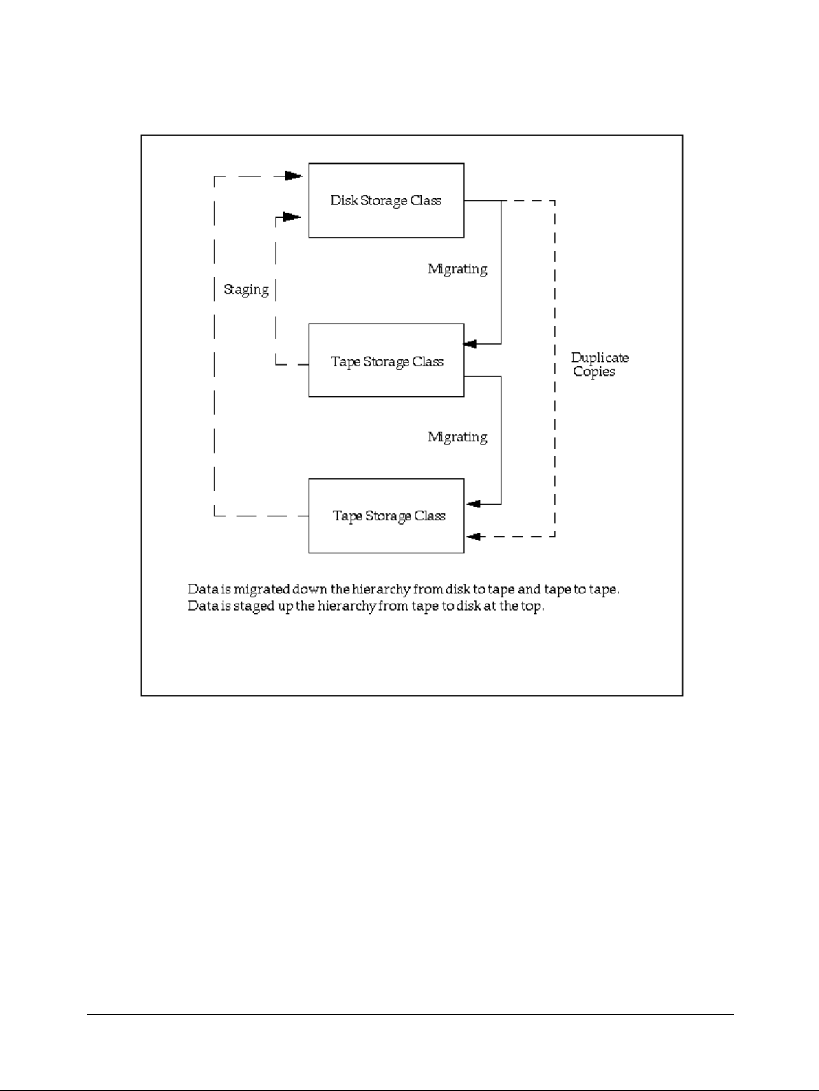
Figure 1-1 Migrate and Stage Operations ............................................................................. 24
Figure 1-2 Relationship of HPSS Data Structures ................................................................ 25
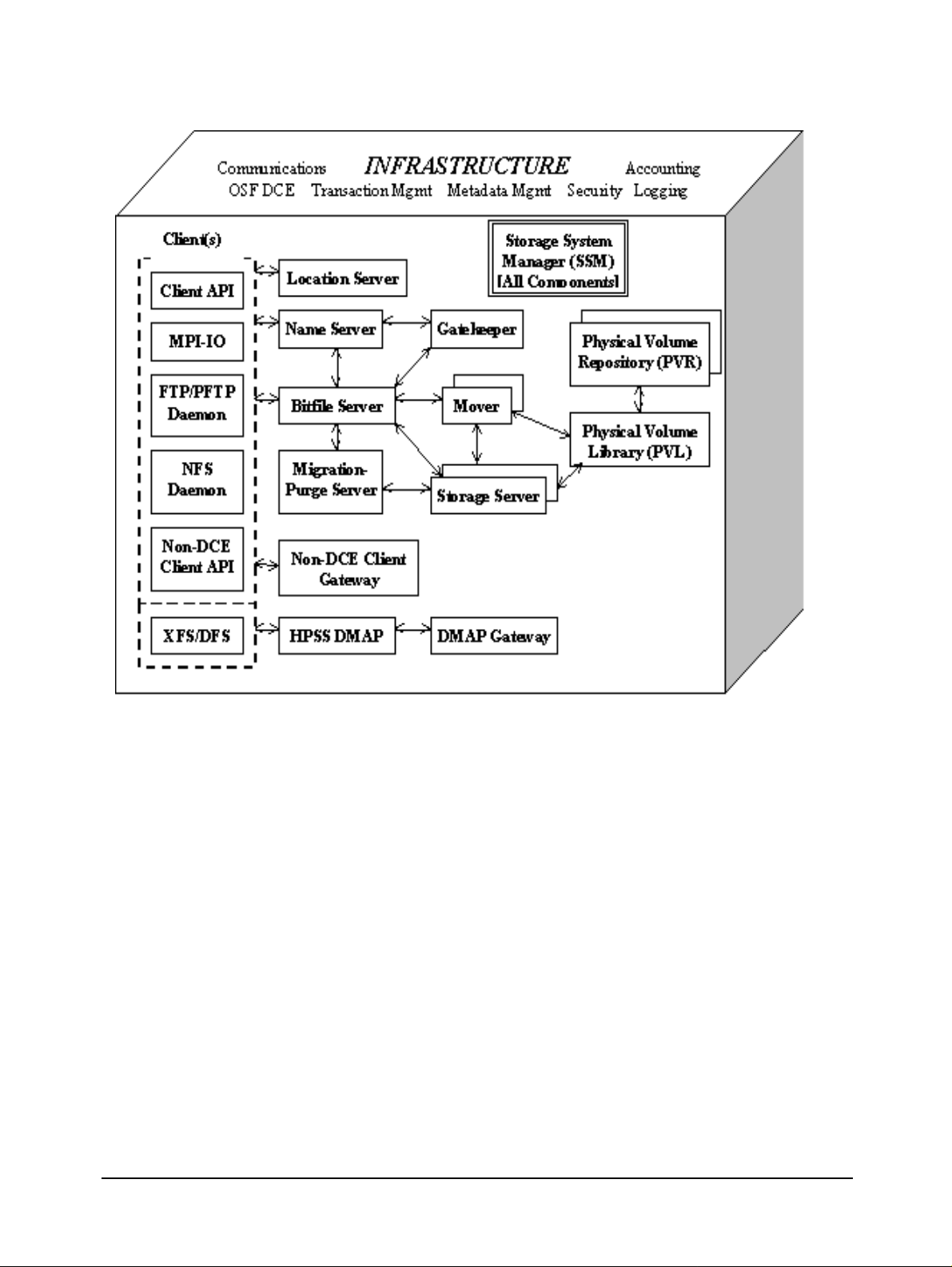
Figure 1-3 The HPSS System ............................................................................................... 26
Figure 2-1 The Relationship of Various Server Data Structures .......................................... 63
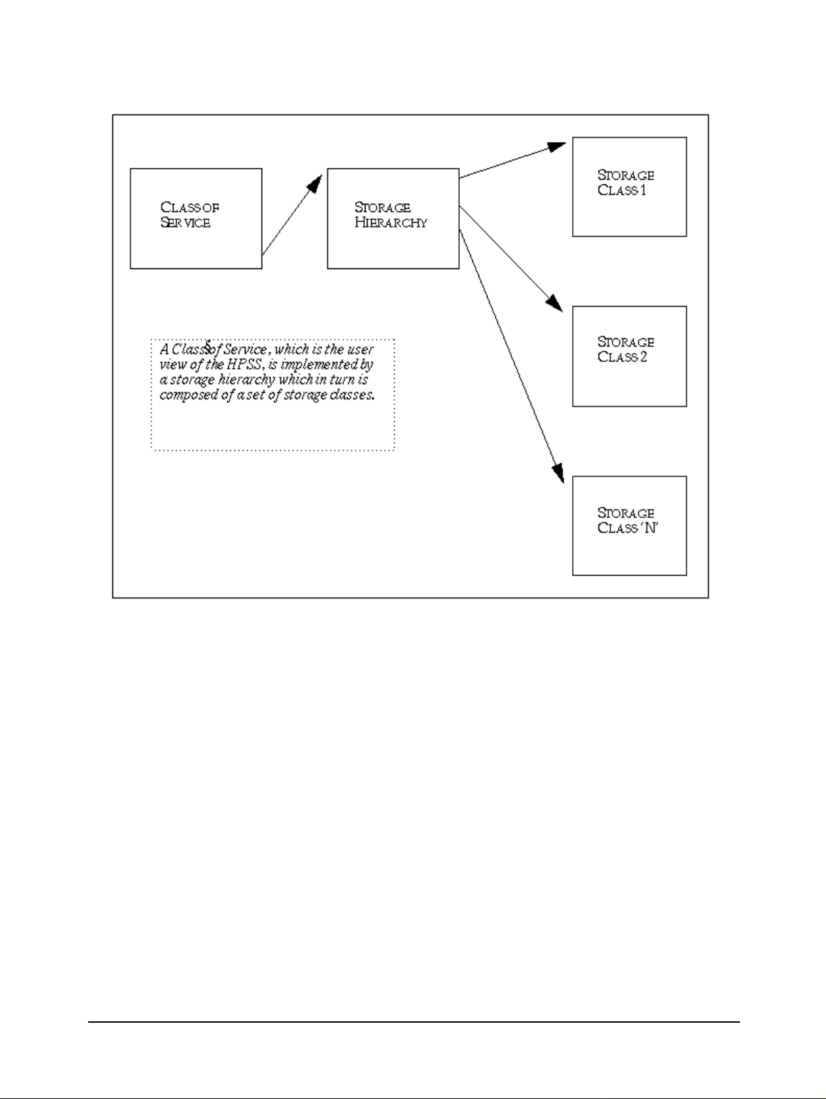
Figure 2-2 Relationship of Class of Service, Storage Hierarchy, and Storage Class ............ 93
Figure 6-1 HPSS Health and Status Window ..................................................................... 252
Figure 6-2 HPSS Logon Window ....................................................................................... 255
Figure 6-3 HPSS Global Configuration screen ................................................................... 256
Figure 6-4 Storage Subsystem Configuration window ....................................................... 260
Figure 6-5 HPSS Servers Window ...................................................................................... 264
Figure 6-6 Basic Server Configuration Window ................................................................ 265
Figure 6-7 Migration Policy Configuration Window .......................................................... 282
Figure 6-8 Purge Policy Window ........................................................................................ 287
Figure 6-9 Accounting Policy Window .............................................................................. 290
Figure 6-10 HPSS Logging Policies Window ...................................................................... 295
Figure 6-11 Logging Policy Window ................................................................................... 299
Figure 6-12 Location Policy Window ................................................................................... 301
Figure 6-13 Remote HPSS Site Configuration Window ....................................................... 304
Figure 6-14 Disk Storage Class Configuration Window ...................................................... 306
Figure 6-15 Tape Storage Class Configuration Window ...................................................... 307
Figure 6-16 Storage Subsystem-Specific Thresholds window ............................................. 313
Figure 6-17 Storage Hierarchy Configuration Window ........................................................ 316
Figure 6-18 Class of Service Configuration Window ........................................................... 319
Figure 6-19 File Family Configuration Window .................................................................. 322
Figure 6-20 Bitfile Server Configuration Window ............................................................... 325
Figure 6-21 DMAP Gateway Configuration Window .......................................................... 330
Figure 6-22 Gatekeeper Server Configuration window ........................................................ 332
Figure 6-23 Logging Client Configuration Window ............................................................ 334
Figure 6-24 Logging Daemon Configuration Window ......................................................... 337
Figure 6-25 Metadata Monitor Configuration window ......................................................... 340
Figure 6-26 Migration/Purge Server Configuration Window ............................................... 342
Figure 6-27 Mover Configuration window ........................................................................... 346
Figure 6-28 Name Server Configuration Window ................................................................ 355
Figure 6-29 NFS Daemon Configuration Window (left side) .............................................. 359
Figure 6-30 NFS Daemon Configuration window (right side) ............................................. 360
Figure 6-31 Non-DCE Client Gateway Configuration Window ........................................... 368
Figure 6-32 PVL Server Configuration Window .................................................................. 371
Figure 6-33 3494 PVR Server Configuration Window ......................................................... 374
Figure 6-34 3495 PVR Server Configuration Window ......................................................... 375
Figure 6-35 3584 LTO PVR Server Configuration Window ................................................ 376
HPSS Installation Guide September 2002 13
Release 4.5, Revision 2
Page 14

Figure 6-36 AML PVR Server Configuration Window ........................................................ 377
Figure 6-37 STK PVR Server Configuration Window ......................................................... 378
Figure 6-38 STK RAIT PVR Server Configuration Window ............................................... 379
Figure 6-39 Operator PVR Server Configuration Window .................................................. 380
Figure 6-40 Disk Storage Server Configuration Window ..................................................... 396
Figure 6-41 Tape Storage Server Configuration Window .................................................... 397
Figure 6-42 HPSS Devices and Drives Window .................................................................. 403
Figure 6-43 Disk Mover Device and PVL Drive Configuration Window ............................ 404
Figure 6-44 Tape Mover Device and PVL Drive Configuration Window ........................... 405
Figure 7-1 DFS/HPSS XDSM Architecture ....................................................................... 438
Figure H-1 HA HPSS Architecture ...................................................................................... 536
Figure H-2 Adding a Cluster Definition .............................................................................. 550
Figure H-3 Adding Cluster Nodes ....................................................................................... 551
Figure H-4 Adding an IP-based Network ............................................................................ 552
Figure H-5 Adding a Non IP-based Network ...................................................................... 552
Figure H-6 Adding an Ethernet Boot Adapter ..................................................................... 554
Figure H-7 Adding an Ethernet Standby Adapter ................................................................ 554
Figure H-8 Adding an Ethernet Service Adapter ................................................................. 555
Figure H-9 Adding a Serial Adapter .................................................................................... 555
Figure H-10 Adding a Resource Group ................................................................................. 556
Figure H-11 Configuring a Resource Group .......................................................................... 557
Figure H-12 Adding an Application Server ........................................................................... 562
Figure H-13 Adding an Application Server to a Resource Group ......................................... 563
Figure H-14 Adding a Custom Verification Method ............................................................. 564
Figure H-15 Configuring AIX Error Notification .................................................................. 566
Figure H-16 Configuring Cluster Event Notification ............................................................ 567
Figure H-17 sample output from ‘clstat -a’ ........................................................................... 568
Figure H-18 Starting Cluster Services ................................................................................... 571
Figure H-19 Verifying the Cluster ......................................................................................... 572
Figure H-20 Moving a Resource Group ................................................................................ 574
14 September 2002 HPSS Installation Guide
Release 4.5, Revision 2
Page 15

List of Tables
Table 1-1 HPSS Client Interface Platforms ......................................................................... 37
Table 2-1 Cartridge/Drive Affinity Table ............................................................................ 56
Table 2-2 Gatekeeping Call Parameters .............................................................................. 90
Table 2-3 Suggested Block Sizes for Disk .......................................................................... 98
Table 2-4 Suggested Block Sizes for Tape .......................................................................... 99
Table 2-5 HPSS Dynamic Variables (Subsystem Independent) ........................................ 122
Table 2-6 HPSS Dynamic Variables (Subsystem Specific) .............................................. 123
Table 2-7 HPSS Static Configuration Values .................................................................... 125
Table 2-8 Paging Space Info .............................................................................................. 135
Table 3-1 Network Options ............................................................................................... 161
Table 3-2 PFTP Client Stanza Fields ................................................................................. 163
Table 3-3 PFTP Client Interfaces Stanza Fields ................................................................ 166
Table 3-4 Multinode Table Stanza Fields .......................................................................... 168
Table 3-5 Realms to DCE Cell Mappings Stanza Fields ................................................... 169
Table 3-6 Network Options Stanza Fields ......................................................................... 171
Table 4-1 Installation Package Sizes and Disk Requirements ........................................... 206
Table 6-1 Global Configuration Variables ........................................................................ 256
Table 6-2 Storage Subsystem Configuration Variables ..................................................... 260
Table 6-3 Basic Server Configuration Variables ............................................................... 266
Table 6-4 Migration Policy Configuration Variables ........................................................ 283
Table 6-5 Purge Policy Configuration Variables ............................................................... 288
Table 6-6 Accounting Policy Configuration Variables ..................................................... 291
Table 6-7 Logging Policies List Configuration Variables ................................................. 295
Table 6-8 Logging Policy Configuration Variables .......................................................... 299
Table 6-9 Location Policy Configuration Variables .......................................................... 301
Table 6-10 Remote HPSS Site Configuration Fields ........................................................... 304
Table 6-11 Storage Class Configuration Variables ............................................................. 308
Table 6-12 Storage Subsystem-Specific Thresholds Variables ........................................... 314
Table 6-13 Storage Hierarchy Configuration Variables ...................................................... 317
Table 6-14 Class of Service Configuration Variables ......................................................... 319
Table 6-15 Configure File Family Variables ....................................................................... 323
Table 6-16 Bitfile Server Configuration Variables .............................................................. 326
Table 6-17 DMAP Gateway Configuration Variables ........................................................ 330
Table 6-18 Gatekeeper Configuration Fields ....................................................................... 332
Table 6-19 Log Client Configuration Variables .................................................................. 334
Table 6-20 Log Daemon Configuration Variables .............................................................. 338
Table 6-21 Metadata Monitor Configuration Variables ...................................................... 341
Table 6-22 Migration/Purge Server Configuration Variables ............................................. 343
Table 6-23 Mover Configuration Variables ......................................................................... 346
Table 6-24 IRIX System Parameters ................................................................................... 351
HPSS Installation Guide September 2002 15
Release 4.5, Revision 2
Page 16

Table 6-25 Solaris System Parameters ................................................................................ 352
Table 6-26 Linux System Parameters .................................................................................. 353
Table 6-27 Name Server Configuration Variables .............................................................. 356
Table 6-28 NFS Daemon Configuration Variables ............................................................. 361
Table 6-29 Non-DCE Client Gateway Configuration Variables ......................................... 368
Table 6-30 Physical Volume Library Configuration Variables ........................................... 372
Table 6-31 Physical Volume Repository Configuration Variables ..................................... 380
Table 6-32 Storage Server Configuration Variables ............................................................ 397
Table 6-33 Device/Drive Configuration Variables .............................................................. 405
Table 6-35 Recommended Settings for Tape Devices ......................................................... 411
Table 6-34 Supported Platform/Driver/Tape Drive Combinations ..................................... 411
Table 7-1 Parallel FTP Daemon Options ........................................................................... 423
Table 7-2 Banner Keywords .............................................................................................. 428
Table 7-3 Directory Export Options .................................................................................. 432
Table 7-4 LogRecordMask Keywords ............................................................................... 451
16 September 2002 HPSS Installation Guide
Release 4.5, Revision 2
Page 17

Preface
Conventions Used in This Book
Example commands that should be typed at a command line will be proceeded by a percent sign
(‘%’) and be presented in a boldface courier font:
Names of files, variables, and variable values will appear in a boldface courier font:
Any text preceded by a pound sign (‘#’) should be considered shell script comment lines:
% sample command
Sample file, variable, or variable value
# This is a comment
HPSS Installation Guide September 2002 17
Release 4.5, Revision 2
Page 18

18 September 2002 HPSS Installation Guide
Release 4.5, Revision 2
Page 19

Chapter 1 HPSS Basics
1.1 Introduction
The High Performance Storage System (HPSS) is software that provides hierarchical storage
management and services for very large storage environments. HPSS may be of interest in
situations having present and future scalability requirements that are very demanding in terms of
total storage capacity, file sizes, data rates, number of objects stored, and numbers of users. HPSS
is part of an open, distributed environment based on OSF Distributed Computing Environment
(DCE) products that form the infrastructure of HPSS. HPSS is the result of a collaborative effort by
leading US Government supercomputer laboratories and industry toaddressveryreal,very urgent
high-end storage requirements. HPSS is offered commercially by IBM Worldwide Government
Industry, Houston, Texas.
HPSS provides scalable parallel storage systems for highly parallel computersas well as traditional
supercomputers and workstation clusters. Concentrating on meeting the high end of storage
system and data management requirements,HPSS isscalable and designed to storeup topetabytes
(1015) of data and to use network-connected storage devices to transfer data at rates up to multiple
gigabytes (109) per second.
HPSS provides a large degree of control for the customer site to manage their hierarchical storage
system. Using configuration information defined by the site, HPSS organizes storage devices into
multiple storage hierarchies. Based on policy information defined by the site and actual usage
information, data are then moved to the appropriate storage hierarchy and to appropriate levels in
the storage hierarchy.
1.2 HPSS Capabilities
A central technical goal of HPSS is to move large files between storage devices and parallel or
clustered computers at speeds many times faster than today’s commercialstorage system software
products, and to do this in a way that is more reliable and manageable than ispossible with current
systems. In order to accomplish this goal, HPSS is designed and implemented based on the
concepts described in the following subsections.
1.2.1 Network-centered Architecture
The focus of HPSS is the network, not a single server processor as in conventional storage systems.
HPSS provides servers and movers that can be distributed across a high performance network to
HPSS Installation Guide September 2002 19
Release 4.5, Revision 2
Page 20

Chapter 1 HPSS Basics
provide scalability and parallelism. The basis for this architecture is the IEEE Mass Storage System
Reference Model, Version 5.
1.2.2 High Data Transfer Rate
HPSS achieves high data transfer rates by eliminating overhead normally associated with data
transfer operations. In general, HPSS servers establish transfer sessions but are not involved in
actual transfer of data.
1.2.3 Parallel Operation Built In
The HPSS Application Program Interface (API) supports parallel or sequential access to storage
devices by clients executing parallel or sequential applications. HPSS also provides a Parallel File
Transfer Protocol. HPSS can even manage data transfers in a situation where the number of data
sources and destination are different. Parallel data transfer is vital in situations that demand fast
access to very large files.
1.2.4 A Design Based on Standard Components
HPSS runs on UNIX with no kernel modifications and is written in ANSI C and Java. It uses the
OSF Distributed Computing Environment (DCE) and Encina from Transarc Corporation as the
basis for its portable, distributed, transaction-based architecture. These components are offered on
many vendors’ platforms. Source code is available to vendors and users for porting HPSS to new
platforms. HPSS Movers and the Client API have been ported to non-DCE platforms. HPSS has
been implemented on the IBM AIX and Sun Solaris platforms. In addition, selected components
have been ported toother vendor platforms. Thenon-DCE Client API andMover have been ported
to SGI IRIX, while the Non-DCE Client API has also been ported to Linux. Parallel FTP client
software has been ported to a number of vendor platforms and is also supported on Linux. Refer
to Section 1.4: HPSS Hardware Platforms on page 37 and Section 2.3: Prerequisite Software
Considerations on page 46 for additional information.
1.2.5 Data Integrity Through Transaction Management
Transactional metadata management and Kerberos security enable a reliable design that protects
user data both from unauthorized use and from corruption or loss. A transaction is an atomic
grouping of metadata management functions that either take place together, or none of them take
place. Journaling makes it possible to back out any partially complete transactions if a failure
occurs. Transaction technology is common in relational data management systems but not in
storage systems. HPSS implements transactions through Transarc’s Encina product. Transaction
management is the key to maintaining reliability and security while scaling upward into a large
distributed storage environment.
1.2.6 Multiple Hierarchies and Classes of Services
Most other storage management systems support simple storage hierarchies consisting of one kind
of disk and one kind of tape. HPSS provides multiple hierarchies, which are particularly useful
when inserting new storage technologies over time. As new disks, tapes, or optical media are
20 September 2002 HPSS Installation Guide
Release 4.5, Revision 2
Page 21

added, new classes of service can be set up. HPSS files reside in a particular class of service which
users select based on parameters such as file size and performance. A class of service is
implemented by a storage hierarchy which in turn consists of multiple storage classes, as shown in
Figure 1-2. Storage classes are used to logically group storage media to provide storage for HPSS
files. A hierarchy may be as simple as a single tape, or it may consist of two or more levels of disk,
disk array, and local tape. The user can even set up classes ofservice so thatdata from an older type
of tape is subsequently migrated to a new type of tape. Such a procedure allows migration to new
media over time without having to copy all the old media at once.
1.2.7 Storage Subsystems
To increase the scalability of HPSS in handling concurrent requests, the concept of Storage
Subsystem has been introduced. Each Storage Subsystem contains a single Name Server and Bitfile
Server. If migration and purge are needed for the storage subsystem, then the Storage Subsystem
will also contain a Migration / Purge Server. A Storage Subsystem must also contain a single Tape
Storage Server and/or a single Disk Storage Server. All other servers exist outside of Storage
Subsystems. Data stored within HPSS is assigned to different Storage Subsystems based on
pathname resolution. A pathname consisting of / resolves to the root Name Server.The root Name
Server is the Name Server specified in the Global Configuration file. However, if the pathname
contains junction components, it may resolve to a Name Server in a different Storage Subsystem.
For example, the pathname /JunctionToSubsys2 could lead to the root fileset managed by the
Name Server in Storage Subsystem 2. Sites which do not wish to partition their HPSS through the
use of Storage Subsystems will effectively be running an HPSS with a single Storage Subsystem.
Note that sites are not required to use multiple Storage Subsystems.
Chapter 1 HPSS Basics
1.2.8 Federated Name Space
Federated Name Space supports data access between multiple, separate HPSS systems. With this
capability, a user may access files in all or portions of a separate HPSS system using any of the
configured HPSS interfaces. To create a Federated Name Space, junctions are created to point to
filesets in a different HPSS system. For security purposes, access to foreign filesets is not supported
for NFS, or for end-users of FTP and the Non-DCE Gateway when only the local password file is
used for authentication.
1.3 HPSS Components
The components of HPSS include files, filesets, junctions, virtual volumes, physical volumes,
storage segments, metadata, servers, infrastructure, user interfaces, a management interface, and
policies. Storage and file metadata are represented by data structures that describe the attributes
and characteristics of storage system componentssuch as files, filesets, junctions,storagesegments,
and volumes. Servers are the processes that control the logic of the system and control movement
of the data. The HPSS infrastructure provides the services that are used by all the servers for
standard operations such as sending messages and providing reliable transaction management.
User interfaces provide several different views of HPSS to applications with different needs. The
management interface provides a way toadminister and control the storage systemand implement
site policy.
These HPSS components are discussed below in Sections 1.3.1 through 1.3.7.
HPSS Installation Guide September 2002 21
Release 4.5, Revision 2
Page 22

Chapter 1 HPSS Basics
1.3.1 HPSS Files, Filesets, Volumes, Storage Segments and Related Metadata
The components used to define the structure of the HPSS name space are filesets and junctions.The
components containing user data include bitfiles, physical and virtual volumes, and storage
segments. Components containing metadata describing the attributes and characteristics of files,
volumes, and storage segments, include storage maps, classes of service, hierarchies, and storage
classes.
• Files (Bitfiles). Files in HPSS, called bitfiles in deference to IEEE Reference Model
terminology, are logical strings of bytes, even though a particular bitfile may have a
structure imposed by its owner. This unstructured view decouples HPSS from any
particular file management system that host clients of HPSS might have. HPSS bitfile size
is limited to 2 to the power of 64 minus 1 (264 - 1) bytes.
Each bitfile is identified by a machine-generated name called a bitfile ID. It may also have
a human readable name. It is the job of the HPSS Name Server (discussed in Section 1.3.2)
to map a human readable name to a bitfile's bitfile ID. By separating human readable
names from the bitfiles and their associated bitfile IDs, HPSS allows sites to use different
Name Servers to organize their storage. There is, however, a standard Name Server
included with HPSS.
• Filesets. A fileset is a logical collection of files that can be managed as a single
administrative unit, or more simply, a disjoint directory tree. A fileset has two identifiers:
a human readable name, and a 64-bit integer. Both identifiers are unique to a given DCE
cell.
• Junctions.A junction is a Name Server object that is used to point to a fileset. This fileset
may belong to the same Name Server or to a different Name Server. The ability to point
junctions allows HPSS users to traverse to differentStorage Subsystems and to traverse to
different HPSS systems via the Federated Name Space. Junctions are components of
pathnames and are the mechanism which implements this traversal.
• File Families. HPSS files can be grouped into families. All files in a given family are
recorded on a set of tapes assigned to the family. Only files from the given family are
recorded on these tapes. HPSS supports grouping files on tape volumes only. Families can
only be specified by associating the family with a fileset. All files created in the fileset
belong to the family. When one of these files is migrated from disk to tape, it is recorded on
a tape with other files in the same family. If no tape virtual volume is associated with the
family,a blank tape is reassigned from the default family.The family affiliation is preserved
when tapes are repacked.
• Physical Volumes. A physical volume is a unit of storage media on which HPSS stores
data. The media can be removable (e.g., cartridge tape, optical disk) or non-removable
(magnetic disk). Physical volumes may also be composite media, such as RAID disks, but
must be represented by the host OS as a single device.
Physical volumes are not visible to the end user. The end user simply stores bitfiles into a
logically unlimited storage space. HPSS, however, must implement this storage on a
variety of types and quantities of physical volumes.
For a list of the tape physical volume types supported by HPSS, see Table 2-4: Suggested
Block Sizes for Tape on page 99.
22 September 2002 HPSS Installation Guide
Release 4.5, Revision 2
Page 23

Chapter 1 HPSS Basics
• Virtual Volumes. A virtual volume is used by the Storage Server to provide a logical
abstraction or mapping of physical volumes. A virtual volume may include one or more
physical volumes. Striping of storage media is accomplished by the Storage Servers by
collecting more than one physical volume into a single virtual volume. A virtual volume is
primarily used inside of HPSS,thus hidden from the user,but its existence benefits theuser
by making the user’s data independent of device characteristics. Virtual volumes are
organized as strings of bytes up to 2
64-1
bytes in length that can be addressed by an offset
into the virtual volume.
• Storage Segments.A storage segment is an abstract storage object which is mapped onto
a virtual volume. Each storage segment is associated with a storage class (defined below)
and has a certain measure of location transparency. The Bitfile Server (discussed in Section
1.3.2) uses both disk and tape storage segments as its primary method of obtaining and
accessing HPSS storage resources. Mappings of storage segments onto virtual volumes are
maintained by the HPSS Storage Servers (Section 1.3.2).
• Storage Maps. A storage map is a data structure used by Storage Servers to manage the
allocation of storage space on virtual volumes.
• Storage Classes. A storage class defines a set of characteristics and usage parameters to
beassociated with a particular grouping of HPSS virtual volumes. Each virtual volumeand
its associated physical volumes belong to a single storage class in HPSS. Storage classes in
turn are grouped to form storage hierarchies (see below). An HPSS storage class is used to
logically group storage media to provide storage for HPSS files with specific intended
usage, similar size and usage characteristics.
• Storage Hierarchies. An HPSS storage hierarchy defines the storage classes on which
files in that hierarchy are to be stored. A hierarchy consists of multiple levels of storage,
with each level representing a different storage class. Files are moved up and down the
hierarchy via migrate and stage operations based on usage patterns, storage availability,
and site policies. For example, a storage hierarchy might consist of a fast disk, followed by
a fast data transfer and medium storage capacity robot tape system, which in turn is
followed by a large data storage capacity but relatively slow data transfer tape robot
system. Files are placed on a particular level in the hierarchy depending upon the
migration levels that are associated with each level in the hierarchy. Multiple copies are
controlled by this mechanism. Also data can be placed at higher levels in the hierarchy by
staging operations. The staging and migrating of data is shown in Figure 1-1.
• Class of Service (COS). Each bitfile has an attribute called Class Of Service. The COS
defines a set of parameters associated with operational and performance characteristics of
a bitfile. The COS results in the bitfile being stored in a storage hierarchy suitable for its
anticipated and actual size and usage characteristics. Figure 1-2 shows the relationship
between COS, storage hierarchies, and storage classes.
HPSS Installation Guide September 2002 23
Release 4.5, Revision 2
Page 24
Chapter 1 HPSS Basics
Figure 1-1 Migrate and Stage Operations
24 September 2002 HPSS Installation Guide
Release 4.5, Revision 2
Page 25
Chapter 1 HPSS Basics
Figure 1-2 Relationship of HPSS Data Structures
1.3.2 HPSS Core Servers
HPSS servers include the Name Server, Bitfile Server, Migration/Purge Server, Storage Server,
Gatekeeper Server, Location Server, DMAP Gateway, Physical Volume Library, Physical Volume
Repository, Mover, Storage System Manager, and Non-DCE Client Gateway. Figure 1-3 provides a
simplified view of the HPSS system. Each major server component is shown, along with the basic
control communications paths (thin arrowed lines). The thick line reveals actual data movement.
Infrastructure items (those components that “glue together” the distributed servers) are shown at
the top of the cube ingrayscale. These infrastructure items are discussed in Section 1.3.4.HPSSuser
interfaces (the clients listed in the figure) are discussed in Section 1.3.5.
HPSS Installation Guide September 2002 25
Release 4.5, Revision 2
Page 26
Chapter 1 HPSS Basics
Figure 1-3 The HPSS System
• Name Server (NS). The NS translates a human-oriented name to an HPSS object identifier.
Objects managed by the NSarefiles,filesets, directories, symbolic links, junctions andhard
links. The NS provides access verification to objects and mechanisms for manipulating
access to these objects. The NS provides a Portable Operating System Interface (POSIX)
view of the name space. This name space is a hierarchical structure consisting of
directories,files,andlinks. Filesets allow collections of NS objects to bemanaged asasingle
administrative unit. Junctions are used to link filesets into the HPSS name space.
• Bitfile Server (BFS). The BFS provides the abstraction of logical bitfiles to its clients. A
bitfile is identified by a BFS-generated name called a bitfile ID. Clients may reference
portions of a bitfile by specifying the bitfile ID and a starting address and length. The reads
and writes to a bitfile are random, and BFS supports the notion of holes (areas of a bitfile
where no data has been written). The BFS supports parallel reading and writing of data to
bitfiles. The BFS communicates with the storage segment layer interface of the Storage
Server (see below) to support the mapping of logical portions of bitfiles onto physical
storage devices. The BFS supports the migration, purging, and staging of data in a storage
hierarchy.
26 September 2002 HPSS Installation Guide
Release 4.5, Revision 2
Page 27

Chapter 1 HPSS Basics
• Migration/Purge Server (MPS). The MPS allows the local site to implement its storage
management policies by managing the placement of data on HPSS storage media using
site-defined migration and purge policies. By making appropriate calls to the Bitfile and
Storage Servers, MPS copies data to lower levels in the hierarchy (migration), removes data
fromthecurrentlevelonce copies have been made (purge), or moves databetween volumes
at the same level (lateral move). Based on the hierarchy configuration, MPS can be directed
to create duplicate copies of data when it is being migrated from disk or tape. This is done
by copying the data to one or more lower levels in the storage hierarchy.
There are three types of migration: disk migration, tape file migration, and tape volume
migration. Disk purge should alwaysbe run along withdisk migration. Thedesignation disk
or tape refers to the type ofstorage class that migration is runningagainst. See Section 2.6.5:
Migration/Purge Server on page 65 for a more complete discussion of the different types of
migration.
Disk Migration/Purge:
The purpose of disk migration is to make one or more copies of disk files to lower levels in
the hierarchy. The number of copies depends on the configuration of the hierarchy. For
disk, migration and purge are separate operations. Any disk storage class which is
configured for migration should be configured for purge as well. Once a file has been
migrated (copied) downwards in the hierarchy, it becomes eligible for purge, which
subsequently removes the file fromthe current level and allows the disk space to be reused.
Tape File Migration:
The purpose of tape file migration is to make a single, additional copy of files in a tape
storage class to a lower level in the hierarchy. It is also possible to move files downwards
instead of copying them. In this case there is no duplicate copy maintained.
That there is no separate purge component to tape file migration, and tape volumes will
require manual repack and reclaim operations to be performed by the admin.
Tape Volume Migration:
The purpose of tape volume migration is to free tape volumes for reuse. Tape volumes are
selected based on being in the EOM map state and containing the most unused space
(caused by users overwriting or deleting files). The remaining segments on these volumes
are either migrated downwards to the next level in the hierarchy, or are moved laterally to
another tape volume at thesamelevel. This results in emptytape volumes which may then
be reclaimed. Note that there is no purge component to tape volume migration. All of the
operations use a move instead of a copy semantic.
MPS runs migration on each storage class periodically using the time interval specified in
the migration policy for that class. See Section 1.3.7: HPSS Policy Modules on page 35 for
details on migration and purge policies. In addition, migration runs can be started
automatically when the warning or critical space thresholds for the storage class are
exceeded. Purge runs are started automatically on each storage class when the free space
in that class falls below the percentage specified in the purge policy.
• Storage Server (SS). The Storage Servers provide a hierarchy of storage objects: storage
segments, virtual volumes, and physical volumes. The Storage Servers translates storage
segment references into virtual volume references and then into physical volume
references,handles the mappingof physicalresourcesinto striped virtual volumestoallow
HPSS Installation Guide September 2002 27
Release 4.5, Revision 2
Page 28

Chapter 1 HPSS Basics
parallel I/O to that set of resources, and schedules the mounting and dismounting of
removable media through the Physical Volume Library (see below).
• Gatekeeper Server (GK). The Gatekeeper Server provides two main services:
A. It provides sites with the ability to schedule the use of HPSS resources using the Gate-
keeping Service.
B. Itprovides siteswith the ability to validate user accounts using the Account Validation
Service.
Both of these services allow sites to implement their own policy.
The default Gatekeeping Service policy is to not do any gatekeeping. Sites may choose to
implement site policy for monitoring authorized callers, creates, opens, and stages. The
BFS will call the appropriate GK API depending on the requests that the site-implemented
policy is monitoring.
The Account Validation Service performs authorizations of user storage charges. A site
may perform no authorization, default authorization, or site-customized authorization
depending on how the Accounting Policy is set up and whether or not a site has written
site-specific account validation code. Clients call this service when creating files, changing
file ownership, or changing accounting information. If Account Validation is enabled, the
Account Validation Service determines if the user is allowed to use a specific account or
gives the user anaccount to use, ifneeded. The Name Serverand Bitfile Server alsocall this
service to perform an authorization check just before account-sensitive operations take
place.
• Location Server (LS). The Location Server actsas aninformation clearinghouseto itsclients
through the HPSS Client API to enable them to locate servers and gather information from
both local and remote HPSS systems. Its primary function is to allow a client to determine
a server's location, its CDS pathname, by knowing other information about the server such
as its object UUID, its server type or its subsystem id. This allows a client to contact the
appropriate server.Usually this is for the Name Server,the Bitfile Server or the Gatekeeper.
• DMAP Gateway (DMG). The DMAP Gateway acts as a conduit and translator between
DFS and HPSS servers. It translates calls between DFS and HPSS, migrates data from DFS
into HPSS, and validates data in DFSand HPSS. In addition, it maintains recordsof all DFS
and HPSS filesets and their statistics.
• Physical Volume Library (PVL). The PVL manages all HPSS physical volumes. It is in
charge of mounting and dismounting sets of physical volumes, allocating drive and
cartridge resources to satisfy mount and dismount requests, providing a mapping of
physical volume to cartridge and of cartridge to Physical Volume Repository (PVR), and
issuing commands to PVRs to perform physical mount and dismount actions. A
requirement of the PVL is the support for atomic mounts of sets of cartridges for parallel
accessto data. Atomic mounts are implemented by the PVL, whichwaits untilallnecessary
cartridge resources for a request are available before issuing mount commands to the
PVRs.
• Physical Volume Repository (PVR). The PVR manages all HPSS cartridges. Clients (e.g.,
the PVL) can ask the PVR to mount and dismount cartridges. Clients can also query the
status and characteristics of cartridges. Every cartridge in HPSS must be managed by
28 September 2002 HPSS Installation Guide
Release 4.5, Revision 2
Page 29

Chapter 1 HPSS Basics
exactly one PVR. Multiple PVRs are supported within an HPSS system. Each PVR is
typically configured to manage the cartridges for one robot utilized by HPSS.
For information on the types of tape libraries supported by HPSS PVRs, see Section 2.4.2:
Tape Robots on page 54.
An Operator PVR is provided for cartridges not under control of a robotic library. These
cartridges are mounted on a set of drives by operators.
• Mover (MVR). The purpose of the Mover is to transfer data from a source device to a sink
device. A device can be a standard I/O device with geometry (e.g., tape, disk) or a device
without geometry (e.g., network, memory). The MVR’s client (typically the SS) describes
the data to be moved and where the data is to be sent. It is the MVR’s responsibility to
actually transfer the data, retrying failed requests and attempting to optimize transfers.
The MVR supports transfers for disk devices, tape devices and a mover protocol that can
be used as a lightweight coordination and flow control mechanism for large transfers.
• Storage System Management (SSM). SSM roles cover a wide range, including aspects of
configuration, initialization, and termination tasks. The SSM monitors and controls the
resources (e.g., servers) of the HPSS storage system in ways that conform to management
policies of a given customer site. Monitoring capabilities include the ability to query the
values of important management attributes of storage system resources and the ability to
receive notifications of alarms and other significant system events. Controlling capabilities
include the ability to start up and shut down servers and the ability to set the values of
management attributes of storage system resourcesand storage system policy parameters.
Additionally, SSM can request that specific operations be performed on resources within
the storage system, such as adding and deleting logical or physical resources. Operations
performedby SSM areusually accomplished through standardHPSS Application Program
Interfaces (APIs).
SSM has three components: (1) the System Manager, which communicates with all other
HPSS components requiring monitoringor control, (2) the Data Server,which provides the
bridge between the System Manager and the Graphical User Interface (GUI), and (3) the
GUI itself, which includes the Sammi Runtime Environment and the set of SSM windows.
• Non-DCE Client Gateway (NDCG). NDCG provides an interface into HPSS for client
programs running on systems lacking access to DCE or Encina services. By linking the
Non-DCE Client API library, instead of the usual ClientAPI library, allAPI calls arerouted
through the NDCG. The API calls are then executed by the NDCG, and the results are
returnedtothe client application. Note thattheNDCG itself must still runon asystem with
DCE and Encina, while it is the client application using the Non-DCE Client API that does
not suffer this restriction.
1.3.3 HPSS Storage Subsystems
Storage subsystems have been introduced starting with the 4.2 release of HPSS. The goal of this
designis to increase the scalability of HPSS by allowingmultiplename and bitfile servers to be used
within a single HPSS system.EveryHPSS system must now bepartitioned into one or morestorage
subsystems. Each storage subsystem contains a single name server and bitfile server. If migration
and purge are needed, then the storage subsystem should contain a single, optional migration/
purgeserver. A storage subsystem must alsocontain one or morestorage servers, but onlyone disk
storage server and one tape storage server are allowed per subsystem. Name, bitfile, migration/
HPSS Installation Guide September 2002 29
Release 4.5, Revision 2
Page 30

Chapter 1 HPSS Basics
purge, and storage servers must now exist within a storage subsystem. Each storage subsystem
may contain zero or one gatekeepers to perform site specific user level scheduling of HPSS storage
requests or account validation. Multiple storage subsystems may share a gatekeeper. All other
servers continue to existoutside of storage subsystems.Sites which do not need multiple name and
bitfile servers are served by running an HPSS with a single storage subsystem.
Storage subsystems are assigned integer ids starting withone. Zerois not a valid storage subsystem
id as servers which areindependent of storage subsystems areassigned to storage subsystem zero.
Storage subsystem ids must be unique. They do not need to be sequential and need not start with
one, but they doso by default unlessthe administrator specifies otherwise.Each storage subsystem
has a user-configurable name as well as a unique id. The name and id may be modified by the
administrator at the time the subsystem is configured but may not be changed afterward. In most
cases, the storage subsystem is referred to by its name, but in atleast one case(suffixes on metadata
file names) the storage subsystem is identified by its id. Storage subsystem names must be unique.
There are two types of configuration metadata used to support storage subsystems: a single global
configuration record, and one storage subsystem configuration record per storage subsystem. The
global configuration record contains a collection of those configuration metadata fields which are
used by multiple servers and that are commonly modified. The storage subsystem records contain
configuration metadata which is commonly used within a storage subsystem.
It is possible to use multiple SFS servers within a single HPSS system. Multiple storage subsystems
are able to run from a single SFS server or using one SFS server per storage subsystem. In practice,
differentmetadata files may be located ondifferentSFS servers on a per file basis depending on the
SFS path given for each file. For configuration and recovery purposes, however, it is desirable for
all of the metadata files forasingle subsystem to reside on a singleSFSserver.This single SFS server
may either be a singleserver which supports the entireHPSS system,or it may supportone or more
subsystems. Those metadata files which belong to the servers which reside within storage
subsystems are considered to belong to the storage subsystem as well. In an HPSS system with
multiple storage subsystems, there are multiple copies of these files, and the name of each copy is
suffixed with the integer id of the subsystem so that it may be uniquely identified (for example
bfmigrrec.1, bfmigrrec.2, etc.).
Metadata files that belong to a subsystem (i.e. files with numeric suffix) should never be shared
between servers. For example, the Bitfile Server in Subsystem #1 has a metadata file called
bfmigrrec.1. This file should only be used by theBFS in Subsystem #1, never by any other server.
The definitions of classes of service, hierarchies, and storage classes apply to the entire HPSS
system and are independent of storage subsystems. All classes of service, hierarchies, and storage
classes are known to all storage subsystems within HPSS. The level of resources dedicated to these
entities by each storage subsystem may differ. It is possible to disable selected classes of service
within given storage subsystems. Although the class of service definitions are global, if a class of
service is disabled within a storage subsystem then the bitfile server in that storage subsystem
never selects that class of service. If a class of service is enabled for a storage subsystem, then there
mustbe a non-zero level of storage resources supporting that class of serviceassignedto the storage
servers in that subsystem.
Data stored within HPSS is assigned to different Storage Subsystems based on pathname
resolution. A pathname consisting of “/” resolves to the root Name Server.The root Name Server is
the Name Server specified in the Global Configuration file. However, if the pathname contains
junction components, it may resolve to a Name Server in a different Storage Subsystem. For
example, the pathname “/JunctionToSubsys2” could lead to the root fileset managed by the Name
Server in Storage Subsystem 2. Sites which do not wish to partition their HPSS through the use of
30 September 2002 HPSS Installation Guide
Release 4.5, Revision 2
Page 31

Storage Subsystems will effectively be runningan HPSSwith a single Storage Subsystem.Note that
sites are not required to use multiple Storage Subsystems.
Since the migration/purge server is contained within the storage subsystem, migration and purge
operate independently in each storage subsystem. If multiple storage subsystems exist within an
HPSS, then there are several migration/purge servers operating on each storage class. Each
migration/purge server is responsible for migration and purge for those storage class resources
contained within its particular storage subsystem. Migration and purge runs are independent and
unsynchronized. This principle holds for other operations such as repack and reclaim as well.
Migration and purge for a storage class may be configured differently for each storage subsystem.
It is possible to set up a single migration or purge policy which applies to a storage class across all
storage subsystems (to make configuration easier), but it is also possible to control migration and
purge differently in each storage subsystem.
Storage class thresholds may be configured differently for each storage subsystem. It is possible to
set up a single set of thresholds which apply to a storage class across all storage subsystems, but it
is also possible to control the thresholds differently for each storage subsystem.
1.3.4 HPSS Infrastructure
Chapter 1 HPSS Basics
The HPSS infrastructure items (see Figure 1-3) are those components that “glue together” the
distributed servers. While each HPSS server component provides some explicit functionality, they
must all work together to provide users with a stable, reliable, and portable storage system. The
HPSS infrastructure components common among servers that tie servers together are discussed
below.
• Distributed Computing Environment (DCE). HPSS uses the Open Software Foundation's
Distributed Computing Environment (OSF DCE) as the basic infrastructure for its
architectureand high-performancestorage system control. DCE was selected becauseof its
wide adoption among vendors and its near industry-standard status. HPSS uses the DCE
Remote Procedure Call (RPC) mechanism for control messages and the DCE Threads
package for multitasking. The DCE Threads package is vital for HPSS to serve large
numbers of concurrent users and to enable multiprocessing of its servers. HPSS also uses
DCE Security as well as Cell and Global Directory services.
Most HPSS servers, with the exception of the MVR, PFTPD, and logging services (see
below), communicate requests and status (control information) viaRPCs.HPSS does not use
RPCs to move user data. RPCs provide a communication interface resembling simple, local
procedure calls.
• Transaction Management.Requests to perform actions, such as creating bitfiles or
accessing file data, result in client-server interactions between software components. The
problemwithdistributed servers working together on acommonjob is that one server may
fail or not be able to do its part. When such an event occurs, it is often necessary to abort
the job by backing off all actions made by all servers on behalf of the job.
Transactional integrity to guarantee consistency of server state and metadata is required in
HPSS in case a particular component fails. As a result, a product named Encina, from
Transarc Corporation, was selected to serve as the HPSS transaction manager. This
selection was based on functionality and vendor platform support. Encina provides begincommit-abort semantics, distributed two-phase commit, and nested transactions. It
HPSS Installation Guide September 2002 31
Release 4.5, Revision 2
Page 32

Chapter 1 HPSS Basics
provides HPSS with an environment in which a job or action that requires the work of
multiple servers either completes successfully or is aborted completely within all servers.
• Metadata Management. Each HPSS server component has system state and resource data
(metadata) associated with the objects it manages. Each server with non-volatile metadata
requires the ability to reliably store its metadata. The metadata management performance
must also be able to scale as the number of object instances grow. In addition, access to
metadata by primary and secondary keys is required.
The Encina Structured File Server (SFS) product serves as the HPSS Metadata Manager
(MM). SFS provides B-tree clustered file records, relative sequence file records, recordand
field level access, primary and secondary keys, and automatic byte ordering between
machines. SFS is also fully integrated with the Encina’s transaction management
capabilities. As a result, SFS provides transactional consistency and data recovery from
transaction aborts. An HPSS component called the Metadata Monitor (MMON) provides
monitoring of the HPSS Encina SFS, including generating notifications when configurable
metadata space usage thresholds are exceeded.
• Security. HPSS software security provides mechanisms that allow HPSS components to
communicate in an authenticated manner, to authorize access to HPSS objects, to enforce
access control on HPSS objects, and to issue log records for security-related events. The
security components of HPSS provide authentication, authorization, enforcement, audit,
and security management capabilities for the HPSS components. Customer sites may use
the default security policy delivered with HPSS or define their own security policy by
implementing their own version of the security policy module.
◆ Authentication — is responsible for guaranteeing that a principal (a customer identity)
is the entity that is claimed, and that information received from an entity is from that
entity. An additional mechanism is provided to allow authentication of File Transfer
Protocol (FTP) users through a site-supplied policy module.
◆ Authorization — is responsible for enabling an authenticated entityaccess toan allowed
set of resourcesand objects. Authorization enables end user access to HPSS directories
and bitfiles.
◆ Enforcement — is responsible for guaranteeing that operations are restricted to the
authorized set of operations.
◆ Audit — is responsible for generating a log of security-relevant activity. HPSS audit
capabilities allow sites to monitor HPSSauthentication,authorization, and file security
events. File security events include file creation, deletion, opening for I/O, and
attribute modification operations.
◆ Security management — allows the HPSS administrative component to monitor the
underlying DCE security services used by the HPSS security subsystem.
HPSS components that communicatewith each other maintaina joint security context. The
security context for both sides of the communication contains identity and authorization
information for the peer principals as well as an optional encryption key. The security
context identity and authorization information is obtained using DCE security and RPC
services.
Access to HPSS server interfaces is controlled through an Access Control List (ACL)
mechanism. Access for HPSS bitfile data is provided through a distributed mechanism
32 September 2002 HPSS Installation Guide
Release 4.5, Revision 2
Page 33

Chapter 1 HPSS Basics
whereby a user's access permissions to an HPSS bitfile are specified by the HPSS bitfile
authorization agent, the Name Server. These permissions are processed by the bitfile data
authorization enforcement agent, the Bitfile Server.The integrity of the access permissions
is certified by the inclusion of a checksum that is encrypted using the security context key
shared between the HPSS Name Server and Bitfile Server.
• Logging. A logging infrastructure component in HPSS provides an audit trail of server
events. Logged data includes alarms, events, requests, security audit records, status
records, and trace information. Servers send log messages to a Log Client (a server
executing on each hardware platform containing servers that use logging). The Log Client,
which may keep a temporary local copy of logged information, communicates log
messages to a central Log Daemon, which in turn maintains a central log. Depending on
the type of log message, the Log Daemon may send the message to the SSM for display
purposes. When the central HPSS log fills, messages are sent to a secondary log file. A
configuration option allows the filled log to be automatically archived to HPSS. A delog
function is provided to extract and format log records. Delog options support filtering by
time interval, record type, server, and user.
• Accounting. The primary purpose of the HPSS accounting system is to provide the means
to collect information on usage in order to allow a particular site to charge its users for the
use of HPSS resources.
For every account index, the storage usage information is written out to an ASCII text file.
It is the responsibility of the individual site to sort and use this information for subsequent
billing based on site-specific charging policies. For more information on the HPSS
accounting policy, refer to Section 1.3.7.
1.3.5 HPSS User Interfaces
Asindicated in Figure 1-3, HPSS provides the user with a number oftransferinterfaces as discussed
below.
• File Transfer Protocol (FTP). HPSS provides an industry-standard FTP user interface.
Because standard FTP is a serial interface, data sent to a user is received serially.This does
not mean that the data within HPSS is not stored and retrieved in parallel; it simply means
that the FTP Daemon within HPSS must consolidate its internal parallel transfers into a
serial data transfer to the user. HPSS FTP performance in many cases will be limited not by
the speed of a single storage device, as in most other storage systems, but by the speed of
the data path between the HPSS FTP Daemon and the user’s FTP client.
• Network File System (NFS). TheNFS serverinterfacefor HPSS provides transparent access
to HPSS name spaceobjects and bitfile datafor client systems throughthe NFS service. The
NFS implementation consists of anNFS Daemon and a MountDaemon that provide access
toHPSS, plus server support functions that arenot accessible toNFSclients. The HPSS NFS
service will work withany industry-standard NFS client thatsupports either (or both)NFS
V2 and V3 protocols.
• Parallel FTP (PFTP). The PFTP supports standard FTP commands plus extensions and is
built to optimize performance for storing and retrieving files from HPSS by allowing data
to be transferred in parallel across the network media. The parallel client interfaces have a
syntax similar to FTP but with some extensions to allow the user to transfer data to and
from HPSS across parallel communication interfaces established between the FTP client
HPSS Installation Guide September 2002 33
Release 4.5, Revision 2
Page 34

Chapter 1 HPSS Basics
and the HPSS Movers. This provides the potential for using multiple client nodes as well
as multiple server nodes. PFTP supports transfers via TCP/IP. The FTP client
communicates directly with HPSS Movers to transfer data at rates limited only by the
underlying communications hardware and software.
• Client Application Program Interface (Client API). The Client API is an HPSS-specific
programming interface that mirrors the POSIX.1 specification where possible to provide
ease of use to POSIX application programmers.Additional APIs are also provided to allow
the programmer to take advantage of the specificfeatures provided by HPSS (e.g.,storage/
access hints passed on file creation and parallel data transfers). The Client API is a
programming level interface. It supports file open/create and close operations; file data
and attribute access operations; file name operations; directory creation, deletion, and
access operations; and working directory operations. HPSS users interested in taking
advantage of parallel I/O capabilities in HPSScanadd Client API calls to theirapplications
to utilize parallel I/O. For the specific details of this interface see the HPSS Programmer’s
Reference Guide, Volume 1.
• Non-DCE Client Application Program Interface (Non-DCE Client API). The Non-DCE
Client API is a programming interface that allows the client programthe option of running
on a platform that does not support DCE and Encina. This API does not call HPSS directly.
Instead, it sends network messages to the Non-DCE Client Gateway, which runs on the
target HPSS system. The NDCG then performs the requested Client API calls for the client
and returns the results. The Non-DCE Client API has the same functionality as the
standard Client API with the following exceptions: it does not support ACL functions, it
does not support transactional processing, and it implements its own security interface.
Client authentication is performed in one of three ways: remote DCE login, kerberos
authentication or no authentication (in case of trusted clients).
• MPI-IO Application Programming Interface (MPI-IO API). The MPI-IO API is a subset of
the MPI-2 standard. It gives applications written for a distributed memory programming
modelaninterface that offerscoordinatedaccesstoHPSSfilesfrommultipleprocesses.The
interface also lets applications specify discontiguouspatterns ofaccess to files and memory
buffers using the same “datatype” constructs that the Message-Passing Interface (MPI)
offers. For the specific details of this interface, see the HPSS Programmer’s Reference Guide,
Volume 1, Release 4.5.
• Distributed File System (DFS). Distributed file system services optionally allow HPSS to
interface with Transarc’s DFSTM. DFS is a scalable distributed file system that provides a
uniform view of file data to all users through a global name space. DFS uses the DCE
concept of cells, and allows data access and authorization between clients and servers in
different cells. DFS uses the Episode physical file system which communicates with HPSS
via an XDSM-compliant interface. For the specific details of this interface, refer to Section
7.6: HDM Configuration on page 435.
• XFS. HPSS is capable of interfacing with SGI’s XFS for Linux. XFS is a scalable open-source
journaling file system for Linux that provides an implementation of the Open Group’s
XDSM interface. This essentially allows the XFS file system to become part of an HPSS
storage hierarchy, with file data migrated into HPSS and purged from XFS disk. For the
specific details of this interface, refer to Section 7.6: HDM Configuration on page 435.
34 September 2002 HPSS Installation Guide
Release 4.5, Revision 2
Page 35

1.3.6 HPSS Management Interface
HPSS provides a powerful SSM administration and operations GUI through the use of the Sammi
product from Kinesix Corporation. Detailed information about Sammi can be found in the Sammi
Runtime Reference, Sammi User’s Guide, and Sammi System Administrator’s Guide.
SSM simplifies the management of HPSS by organizing a broadrange of technical data into a series
of easy-to-read graphic displays. SSM allows monitoring and control of virtually all HPSS
processes and resourcesfrom windows that can easily be added, deleted, moved, or overlapped as
desired.
HPSS also provides a command line SSM interface, hpssadm. This tool does not provide all the
functionality of the GUI, but does implement a subset of its frequently used features, such as some
monitoring and some control of servers, devices, storage classes, volumes, and alarms. It is useful
for performing HPSS administration from remote locations where X traffic is slow, difficult, or
impossible, such as fromhome or from scripts. Additionally, hpssadm provides some rudimentary
mass configuration support by means of the ability to issue configuration commands from a batch
script.
Chapter 1 HPSS Basics
1.3.7 HPSS Policy Modules
There are a number of aspects of storage management that probably will differ at each HPSS site.
For instance, sites typically have their own guidelines or policies covering the implementation of
accounting, security, and other storage management operations. In order to accommodate sitespecific policies, HPSS has implemented flexible interfaces to its servers to allow local sites the
freedom to tailor management operations to meet their particular needs.
HPSSpolicies areimplementedusing two differentapproaches.Under thefirst approach—usedfor
migration, purge, and logging policies—sites are provided with a large number of parameters that
may be used to implement local policy. Under the second approach, HPSS communicates
information through a well-defined interface to a policy software module that can be completely
replaced by a site. Under both approaches, HPSS provides a default policy set for users.
• Migration Policy.The migration policy defines the conditions under which data is copied
from one level in a storage hierarchy to one or more lower levels. Each storage class that is
to have data copied from that storage class to a lower levelin the hierarchyhas a migration
policy associated with it. The MPSuses this policy to control when filesarecopied and how
much data is copied from the storage class in a given migration run. Migration runs are
started automatically by the MPS based upon parameters in the migration policy.
Note that the number of copies which migration makes and the location of these copies is
determined by the definition of the storage hierarchy and not by the migration policy.
• Purge Policy. The purge policy defines the conditions under which data that has already
been migrated from a disk storage class can be deleted. Purge applies only to disk storage
classes. Each disk storage class which has a migration policy should also have a purge
policy. Purge runs are started automatically by the MPS based upon parameters in the
purge policy.
HPSS Installation Guide September 2002 35
Release 4.5, Revision 2
Page 36

Chapter 1 HPSS Basics
• Logging Policy. The logging policy controls the types of messages to log. On a per server
basis, the message types to write to the HPSS log may be defined. In addition, for each
server, options to send Alarm, Event, or Status messages to SSM may be defined.
• Security Policy.Sitesecuritypolicy defines the authorization and access controls to be used
for client access to HPSS. Site policy managers were developed for controlling access from
FTP and/or Parallel FTP using either Ident or Kerberos credentials.These access methods
are supported by request using the hpss_pftpd_amgr and an appropriate authentication
manager. The Policy Manager is no longer supported. The Non-DCE Client Gateway
provides three Security Policies: none, Kerberos, and DCE.
HPSS server authentication and authorization use DCE authentication and authorization
mechanisms. Each HPSS server has configuration information that determines the type
and level of DCE security services available/required for the individual server. HPSS
software uses DCE services to determine a caller’s identity via credentials passed by the
caller to the server. Once the identity and authorization information has been obtained,
each HPSS server grants/denies the caller’srequest based on the access controllist (ACLs)
attached to the Security object in the server’s Cell Directory Service (CDS) entry. Access to
the interfaces that modify a server’s internal metadata, generally require control
permission. HPSS security is only as good as the security employed in the DCE cell!
HPSS provides facilities for recording information about authentication and object (file/
directory)creation,deletion, access, and authorizationevents. The security auditpolicy for
each server determines the records that each individual server will generate. All servers
can generate authentication records, while only the Name and Bitfile Servers generate
other object event records.
• Accounting Policy.The accounting policy provides runtime information to the accounting
report utility and to the Account Validation service of the Gatekeeper. It helps determine
what style of accounting should be used and what level of validation should be enforced.
The two types of accounting are site-style and UNIX-style. The site-style approach is the
traditional type of accounting in use by most mass storage systems. Each site will have a
site-specific table (Account Map) that correlates the HPSS account indexnumber with their
local account charge codes. TheUNIX-style approach allows asite to use theuser identifier
(UID) for the account index. The UID is passed along in UNIX-style accounting just as the
account index number is passed along in site-style accounting. The hpss_Chown API or
FTP quote site chown command can be used to assign a file to a new owner.
Account Validationallows a site to perform usage authorization of an account for a user. It
is turned on by enabling the Account Validation field. If Account Validationis enabled, the
accounting style in use at the site is determined by the Accounting Style field. A site policy
module may be implemented by the local site to perform customized account validation
operations. The default Account Validation behavior is performed for any Account
Validation operation that is not overridden by the site policy module.
If Account Validation is not enabled, as in previous versions of HPSS, the accounting style
to use is determined by the GECOS field on the user's DCE account in the DCE registry or
by the HPSS.gecos Extended Registry Attribute (ERA) on the DCE principal in the DCE
registry.
• Location Policy. The location policy defines how Location Servers at a given site will
perform, especially in regards to how often server location information is updated. All
local, replicated Location Servers update information according to the same policy.
36 September 2002 HPSS Installation Guide
Release 4.5, Revision 2
Page 37

• Gatekeeping Policy.The Gatekeeper Server provides a Gatekeeping Service along with an
Account Validation Service. These services provide the mechanism for HPSS to
communicateinformation though a well-defined interface to apolicy softwaremodule that
can be completely written by a site. The site policy code is placed in well-defined shared
libraries for the gatekeeping policy and the accounting policy (/opt/hpss/lib/
libgksite.[a|so] and /opt/hpss/lib/libacctsite.[a|so] respectively) which are linked to the
Gatekeeper Server. The Gatekeeping policy shared library contains a default policy which
does NO gatekeeping. Sites will need to enhance this library to implement local policy
rules if they wish to monitor and load-balance requests.
1.4 HPSS Hardware Platforms
1.4.1 Client Platforms
The following matrix illustrates which platforms support HPSS interfaces.
Table 1-1 HPSS Client Interface Platforms
Chapter 1 HPSS Basics
Platform
IBM AIX X X X X X Anyplatform
Sun Solaris XX X XX
Cray UniCOS X
Intel Teraflop X
Digital Unix X
Hewlett-Packard
HPUX
Silicon Graphics
IRIX (32-bit)
Compaq Tru64 X
Linux (Intel) XX X
Linux
(OpenNAS)
Linux (Alpha) X
PFTP
Client
X
XX
Client
API
Non-DCE
Client API
MPI-IO
DFS
HDM
XFS
HDM
X
NFS,DFS,
and FTP
Clients
running
standard
NFS, DFS,
or FTP
clients,
respectively
The full-function Client API can be ported to any platform that supports Unix, DCE, and Encina.
The PFTP client code and Client API source code for the platforms other than AIX, Linux, and
Solaris listed above is on the HPSS distribution tape. Maintenance of the PFTP and Client API
software on these platforms is the responsibility of the customer, unless a support agreement is
negotiated with IBM. Contact IBM for information on how to obtain thesoftware mentioned above.
HPSS Installation Guide September 2002 37
Release 4.5, Revision 2
Page 38

Chapter 1 HPSS Basics
The MPI-IO API can be ported to any platform that supports a compatible host MPI and the HPSS
Client API (DCE or Non-DCE version). See Section 2.5.6: MPI-IO API on page 60 for determining a
compatible host MPI.
The XFS HDM is supported on standard Intel Linux platforms as well as the OpenNAS network
appliance from Consensys Corp.
1.4.2 Server and Mover Platforms
HPSS currently requires at least one AIX or Solaris machine for the core server components. The
core server machine must include DCE and Encina as prerequisites (see Section 2.3: Prerequisite
Software Considerations on page 46) and must have sufficient processing power and memory to
handle the work load needed by HPSS.
HPSS is a distributed system. The main component that is replicated is the Mover, used for logical
network attachment of storage devices. The Mover is currently supported in two modes of
operation. In the first mode, the Mover is supported on AIX and Solaris platforms, which require
DCE and Encina services. In the second mode, a portion of the Mover runs on the AIX or Solaris
platform (again requiring DCE and Encina), but the portion of the Mover that manages HPSS
devices and transfers data to/from clients runs on platforms that do not require DCE or Encina
services. This second portion of the Mover that handles data transfers is supported on AIX, IRIX
and Solaris.
38 September 2002 HPSS Installation Guide
Release 4.5, Revision 2
Page 39

Chapter 2 HPSS Planning
2.1 Overview
This chapter provides HPSS planning guidelines and considerations to help the administrator
effectively plan, and make key decisions about, an HPSS system. Topics include:
• Requirements and Intended Usages for HPSS on page 43
• Prerequisite Software Considerations on page 46
• Hardware Considerations on page 53
• HPSS Interface Considerations on page 58
• HPSS Server Considerations on page 62
• Storage Subsystem Considerations on page 81
• Storage Policy Considerations on page 81
• Storage Characteristics Considerations on page 91
• HPSS Sizing Considerations on page 105
• HPSS Performance Considerations on page 135
• HPSS Metadata Backup Considerations on page 142
The planning process for HPSS must be done carefully to ensure that the resulting system
satisfies the site’s requirements and operates in an efficient manner. We recommend that the
administrator read the entire document before planning the system.
The following paragraphs describe the recommended planning steps for the HPSS installation,
configuration, and operational phases.
2.1.1 HPSS Configuration Planning
Before beginning the planning process, there is an important issue to consider. HPSS handles large
files much better than it does small files. If at all possible, try to reduce the number of small files
HPSS Installation Guide September 2002 39
Release 4.5, Revision 2
Page 40

Chapter 2 HPSS Planning
that are introduced into your HPSS system. For example, if you plan to use HPSS to backup all of
the PCs in your organization, it would bebest to aggregate theindividual files into largeindividual
files before moving them into the HPSS name space.
The following planning steps must be carefully considered for the HPSS infrastructure
configuration and the HPSS configuration phases:
1. Identify the site’s storage requirements and policies, such as the initial storage system size,
anticipated growth, usage trends, average file size, expected throughput, backup policy.
and availability.For more information, see Section 2.2: Requirements and Intended Usages for
HPSS on page 43.
2. Define the architecture of the entire HPSS system to satisfy the above requirements.The
planning should:
◆ Identify the nodes to be configured as part of the HPSS system.
◆ Identify the disk and tape storage devices to be configured as part of the HPSS system
and the nodes/networks to which each of the devices will be attached. Storagedevices
can be assigned to a number of nodes to allow data transfers to utilize the devices in
parallel without being constrained by the resources of a single node. This capability
also allows the administrator to configure the HPSS system to match the device
performance with the network performance used to transfer the data between the
HPSS Movers and the end users (or other HPSS Movers in the case of internal HPSS
data movement for migration and staging). Refer to Section 2.4 for more discussions
on the storage devices and networks supported by HPSS.
◆ Identify the HPSS subsystems to be configured and how resources will be allocated
among them. Refer to Section 2.7: Storage Subsystem Considerations on page 81 for more
discussion on subsystems.
◆ Identify the HPSS servers to be configured and the node where each of the servers will
run. Refer to Section 2.6:HPSS Server Considerations onpage 62 for morediscussions on
the HPSS server configuration.
◆ Identify the HPSS user interfaces (e.g. FTP, PFTP, NFS,XFS, DFS) to be configured and
the nodes where the components of each user interface will run. Refer to Section 2.5:
HPSS Interface Considerations on page 58 for more discussion on the user interfaces
supported by HPSS.
3. Ensure that the prerequisite software has been purchased, installed, and configured properly in order to satisfy the identified HPSS architecture. Refer to Section 2.3: Prerequisite
Software Considerations on page 46 for moreinformation on the HPSS prerequisite software
requirements.
4. Determine the SFS space needed to satisfy the requirements of the HPSS system. In addition, verify that there is sufficient disk space to configure the space needed by SFS. Refer to
Section 2.10.2: HPSS Metadata Space on page106for more discussions of SFS sizing required
by HPSS.
5. Verify that each of the identified nodes has sufficient resources to handle the work loads
and resources to be imposed on the node. Refer to Section 2.10.3: System Memory and Disk
Space on page 132 for more discussions on the system resource requirements.
40 September 2002 HPSS Installation Guide
Release 4.5, Revision 2
Page 41

Chapter 2 HPSS Planning
6. Define the HPSS storage characteristics and create the HPSS storage space to satisfy the
site’s requirements:
◆ Define the HPSS file families. Refer to Section 2.9.4: File Families on page 105 for more
information about configuring families.
◆ Define filesets and junctions. Refer to Section 8.7: Creating Filesets and Junctions on page
465 for more information.
◆ Define the HPSS storage classes. Referto Section2.9.1: StorageClass on page93 formore
information on the storage class configuration.
◆ Define the HPSS storage hierarchies. Refer to Section 2.9.2: Storage Hierarchy on page
101 for more information on the storage hierarchy configuration.
◆ Define the HPSS classes of service.Refer to Section 2.9.3:Class of Service on page 102 for
more information on the class of service configuration.
◆ Define the migration and purge policy for each storage class. Refer to Section 2.8.1:
Migration Policy on page 82 and Section 2.8.2: Purge Policy on page 84 for more
information on the Migration Policy and Purge Policy configuration, respectively.
◆ Determine the HPSS storage space needed for each storage class. Refer to Section
2.10.1: HPSS Storage Spaceon page 106 for more information on theHPSS storage space
considerations.
◆ Identify the disk and tape media to be imported into HPSS to allow for the creation of
the needed storage space.
7. Define the location policy to be used. Refer to Section 2.8.6: Location Policy on page 89 for
more information.
8. Define the accounting policy to be used. Refer to Section 2.8.3: Accounting Policy and Valida-
tion on page 85 for more information on the Accounting Policy configuration.
9. Define the logging policy for the each of the HPSS servers. Refer to Section 2.8.5: Logging
Policy on page 89 for more information on the Logging Policy configuration.
10. Define the security policy for the HPSS system. Refer to Section 2.8.4: Security Policy on
page 87 for more information on the Security Policy for HPSS.
11. Identify whether or not a Gatekeeper Server will be required. It is required if a site wants
to do Account Validation or Gatekeeping. Refer to Section 2.8.3: Accounting Policy and Vali-
dation on page 85 for more information on Account Validation and Section Section 2.8.7:
Gatekeeping on page 90 for more information on Gatekeeping.
2.1.2 Purchasing Hardware and Software
It is recommended that you not purchase hardware until you have planned your HPSS
configuration. Purchasing the hardware prior to the planning process may result in performance
issues and/or utilization issues that could easily be avoided by simple advance planning.
HPSS Installation Guide September 2002 41
Release 4.5, Revision 2
Page 42

Chapter 2 HPSS Planning
If deciding to purchase Sun or SGI servers for storage purposes, note that OS limitations will only
allow a static number of raw devices to be configured per logical unit (disk drive or disk array).
Solaris currently allows only eight partitions per logical unit (one of which is used by the OS). Irix
currently allows only sixteen partitions per logical unit. These numbers can potentially impact the
utilization of a disk drive or disk array.
Refer to Section 2.10: HPSS Sizing Considerations on page 105 for more information on calculating
the number and size of raw devices that will be needed to meet your requirements.
Refer to Section 2.3: Prerequisite Software Considerations on page 46 for more information on the
required software that will be needed to run HPSS.
When you finally have an HPSS configuration that meets your requirements, it is then time to
purchase the necessary hardware and software.
2.1.3 HPSS Operational Planning
The following planning steps must be carefully considered for the HPSS operational phase:
1. Define the site policy for the HPSS users and SSM users.
◆ Each HPSS user who uses the storage services provided by HPSS should be assigned
an Accounting ID and one or more appropriate Classes of Service (COS) to store files.
◆ Each SSM user (usually an HPSS administrator or an operator) should be assigned an
appropriate SSM security level. The SSM security level defines what functions each
SSM user can perform on HPSS through SSM. Refer to Section 11.1: SSM Security on
page 275 of the HPSS Management Guide for more information on setting up the
security level for an SSM user.
2. Definethesite policy and procedureforrepackingand reclaiming HPSS tape volumes. This
policy should consider how often to repack and reclaim HPSS volumes in the configured
tape storage classes. In addition, the policy must consider when the repack and reclaim
should be performed to minimize the impact on the HPSS normal operations. Refer to
Section 3.7: Repacking HPSS Volumes on page 74 and Section 3.8: Reclaiming HPSS Tape
Virtual Volumes on page 76 (both in the HPSS Management Guide) for more information.
3. Define the site policy and procedure for generating the accounting reports. This policy
should consider how often an accounting report needs to be generated, how to use the
accounting information from the report to produce the desired cost accounting, and
whether the accounting reports need to be archived. Refer to Section 2.8.3: Accounting
Policy and Validation on page 85 and Section 6.6.3: Configure the Accounting Policy on page
289 for more information on defining an Accounting Policy and generating accounting
reports.
4. Determine whether or not gatekeeping (monitoring or load-balancing) will be required. If
so, define and write the site policy code for gatekeeping. Refer to Section 2.8.7: Gatekeeping
on page 90 for more information on Gatekeeping and HPSS Programmers Reference, Volume
1 for guidelines on implementing the Site Interfaces for the Gatekeeping Service.
42 September 2002 HPSS Installation Guide
Release 4.5, Revision 2
Page 43

2.1.4 HPSS Deployment Planning
The successful deployment of an HPSS installation is a complicated task which requires reviewing
customer/system requirements, integration of numerous products and resources, proper training
of users/administrators, and extensive integration testing in the customer environment. Early on,
a set of meetings and documents are required to ensure the resources and intended configuration
of those resources at the customer location can adequately meet the expectations required of the
system. The next step in this process is to help the customer coordinate the availability and
readiness of the resources before the actual installation of HPSS begins. Each one of the products/
resources that HPSS uses must be installed, configured and tuned correctly for the final system to
function and perform as expected. Once installed, a series of tests must be planned and performed
to verify that the system can meet the demands of the final production environment. And finally,
proper training of those administrating the system, as well as those who will use it, is necessary to
make a smooth transition to production.
To help the HPSS system administrators in all of these tasks, a set of procedures in addition to this
document have been developed to assist those involved in this process. The HPSS Deployment
Process contains a detailed outline of what is required to bring an HPSS system online from an
initial introduction and review of the customer environment to the time the system is ready for
production use. The deployment procedures include a time line plus checklist that the HPSS
customer installation/system administration team should use to keep the deployment of an HPSS
system on track. This is the same guide that the HPSS support/deployment team uses to monitor
and check the progress of an installation.
Chapter 2 HPSS Planning
2.2 Requirements and Intended Usages for HPSS
This section provides some guidance for the administrator to identify the site’s requirements and
expectation of HPSS. Issues such as the amount of storage needed, access speed and data transfer
speed, typical usage, security, expected growth, data backup, and conversion from an old system
must be factored into the planning of a new HPSS system.
2.2.1 Storage System Capacity
The amount of HPSS storage space the administrator must plan for is the sum of the following
factors:
• The amount of storage data from anticipated new user accounts.
• The amount of new storage data resulting from normal growth of current accounts.
• The amount of storage space needed to support normal storage management such as
migration and repack.
• The amount of storage data to be duplicated.
Another component of data storage is the amount of metadata space needed for user directories
and other HPSS metadata. Much of this data must be duplicated (called “mirroring”) in real time
on separate storage devices. Refer to Section 2.10.1 and Section 2.10.2 for more information on
determining the needed storage space and metadata space.
HPSS Installation Guide September 2002 43
Release 4.5, Revision 2
Page 44

Chapter 2 HPSS Planning
2.2.2 Required Throughputs
Determinethe requiredorexpected throughputfor the various types of data transfers thattheusers
will perform. Some users want quick access to small amounts of data. Other users have huge
amounts of data they want to transfer quickly, but are willing to wait for tape mounts, etc. In all
cases, plan for peak loads that can occur during certain time periods. These findings must be used
to determine the type of storage devices and network to be used with HPSS to provide the needed
throughput.
2.2.3 Load Characterization
Understanding the kind of load users are putting on an existing file system provides input that can
be used to configure and schedule the HPSS system. What is the distribution of file sizes? How
many files and how much data is moved in each category? How does the load vary with time (e.g.,
over a day, week, month)? Are any of the data transfer paths saturated?
Having this storage system load information helps to configure HPSS so that it can meet the peak
demands. Also based on this information, maintenance activities such as migration, repack, and
reclaim can be scheduled during times when HPSS is less busy.
2.2.4 Usage Trends
To configure the system properly the growth rates of the various categories of storage, as well as
the growth rate of the number of files accessed and data moved in the various categories must be
known. Extra storage and data transfer hardware must be available if the amount of data storage
and use are growing rapidly.
2.2.5 Duplicate File Policy
The policy on duplicating critical files that a site uses impacts the amount of data stored and the
amount of data moved. If all user files are mirrored, the system will require twice as many tape
devices and twice as much tape storage. If a site lets the users control their own duplication of files,
the system may have a smaller amount of data duplicated depending on user needs. Users can be
given control over duplication of their files by allowing them a choice between hierarchies which
provide duplication and hierarchies which do not. Note that only files on disk can be duplicated to
tapes and only if their associated hierarchies are configured to support multiple copies.
2.2.6 Charging Policy
HPSS does not do the actual charging of users for the use of storage system resources. Instead, it
collects information that a site can use to implement a charging policy for HPSS use. The amount
charged for storage system use also will impact the amount of needed storage. If there is no charge
for storage, users will have no incentive to remove files that are outdated and more data storage
will be needed.
44 September 2002 HPSS Installation Guide
Release 4.5, Revision 2
Page 45

2.2.7 Security
The process of defining security requirements is called developing a site security policy. It will be
necessary to map the security requirements into those supported by HPSS. HPSS authentication,
authorization, and audit capabilities can be tailored to a site’s needs.
Authentication and authorization between HPSS servers is done through use of DCE cell security
authentication and authorization services. By default, servers are authenticated using the DCE
secret authentication service, and authorization information is obtained from the DCE privilege
service. The default protection level is to pass authentication tokens on the first remote procedure
call to a server. The authentication service, authorization service, and protection level for each
server can be configured to raise or lower the security of the system. Twocautions should be noted:
(1) raising the protection level to packet integrity or packet privacy will require additional
processing for each RPC, and (2) lowering the authentication service to none effectively removes
the HPSS authentication and authorization mechanisms.This should only be done in a trusted
environment.
Each HPSS server authorizes and enforces access to its interfaces through access control lists
attached to an object (named Security) that is contained in its CDS directory. To be able to modify
server state, control access is required. Generally, this is only given to the DCE principal associated
with the HPSS system administrative component. Additional DCE principals can be allowed or
denied access by setting permissionsappropriately.See Section 6.5.1.2: Server CDSSecurity ACLs on
page 278 for more information.
Chapter 2 HPSS Planning
Securityauditing in each server may be configured to recordall, none, or some security event.Some
sites may choose tolog every client connection;every bitfile creation, deletion, andopen; and every
file management operation. Other sites may choose to log only errors. See the security information
fields in the general server configuration (Section 6.5.1: Configure the Basic Server Information (page
263)) for more details.
User access to HPSS interfaces depends on the interface being used. Access through DFS and the
native Client API uses the DCE authentication and authorization services described above. Access
through the Non-DCE Client API is configurable as described in Section 6.8.11: Non-DCE Client
Gateway Specific Configuration on page 367. Access through NFS is determined based on how the
HPSS directories are exported. Refer to Section 12.2: HPSS Utility Manual Pages on page 293 of the
HPSS Management Guide for more information on NFS exports and the nfsmap utility (Section
12.2.42: nfsmap — Manipulate the HPSS NFS Daemon's Credentials Map (page 418) in the HPSS
Management Guide). FTP or Parallel FTP access may utilize an FTP password file or may utilize the
DCE Registry. Additional FTP access is available using Ident, Kerberos GSS credentials, or DCE
GSS credentials. The Ident and GSS authentication methodsrequirerunningthe hpss_pftpd_amgr
server and an associated authentication manager in place of the standard hpss_pftpd. Refer to the
FTP section of the HPSS User’s Guide for additional details.
2.2.7.1 Cross Cell Access
DCE provides facilities for secure communication between multiple DCE cells (realms/domains)
referred to as Trusted “Cross Cell”. These features use the DCE facilities to provide a trusted
environment between cooperative DCE locations. HPSS uses the DCE Cross Cell features for
authentication and to provide HPSS scalability opportunities. The procedures for inter-connecting
DCE cells are outlined in Section Chapter 11: Managing HPSS Security and Remote System Access on
page 275 of the HPSS Management Guide. The HPSS DFS facilities, Federated Name Space, and
HPSS Parallel FTP can utilize the DCE and HPSS Cross Cell features.
HPSS Installation Guide September 2002 45
Release 4.5, Revision 2
Page 46

Chapter 2 HPSS Planning
The Generic Security Service (GSS) FTP (available from the Massachusetts Institute of Technology,
MIT) and Parallel FTP applications may also take advantage of the Cross Cell features for
authentication and authorization. Use of Kerberos/DCE Credentials with the HPSS Parallel FTP
Daemon requires using the hpss_pftpd_amgr server and an associated authentication manager in
place of the standard hpss_pftpd. Both the GSSFTP from MIT and the krb5_gss_pftp_client
applications may use the Cross Cell features (subject to certain caveats! – See FTP documentation
for details.) The krb5_gss_pftp_client is not distributed by the HPSS project; but may be built from
distributed source by the HPSS sites. It is the site's responsibility to obtain the necessary Kerberos
components (header files, library files, etc.)
Local Location Servers exchange server information with remote Location Servers for both intersubsystem and HPSS Cross Cell communications. It is necessary to add a record to the Remote
Sites metadata file for each remote HPSS system you are connecting to in order to tell each local
Location Server how to contact its remote counterpart. To do this, the Local HPSS will need to
obtain all of the information contained in the Remote HPSS Site Identification fields from the
remote site's Location Policy screen. Similarly, information from the Local site's Location Policy
screen will be required by the Remote HPSS site in the Remote Site's policy file.
ACLs on HPSS CDS Objects and/or HPSS directories/files may need to be added for appropriate
foreign_user and/or foreign_group entries.
2.2.8 Availability
The High Availability component allows HPSS to inter operate with IBM’s HACMP software.
When configured with the appropriate redundant hardware, this allows failures of individual
system components (network adapters, core server nodes, power supplies, etc.) to be overcome,
returning the system to resume servicing requests with minimal downtime. For more information
on the High Availability component, see Appendix G: High Availability (page 535).
2.3 Prerequisite Software Considerations
This section defines the prerequisite software requirements for HPSS. These software products
must be purchased separately from HPSS and installed prior to the HPSS installation and
configuration.
2.3.1 Overview
A summary of the products required to run HPSS is described in the following subsections.
2.3.1.1 DCE
HPSS uses the Distributed Computing Environment (DCE) and operates within a DCE cell. HPSS
requires at least one (1) DCE Security Server and at least one (1) DCE Cell Directory Server.
Anadditional Security Server can be added into the configuration ona differentmachine to provide
redundancy and load balancing, if desired. The same is true for the Cell Directory Server.
46 September 2002 HPSS Installation Guide
Release 4.5, Revision 2
Page 47

Chapter 2 HPSS Planning
For U.S. sites, assuming some level of encryption is desired for secure DCE communication, the
DCE Data Encryption Standard (DES) library routinesare required. For non-U.S. sites or sites desiring
to use non-DES encryption, the DCE User Data Masking Encryption Facility is required. Note that if
either of these products are ordered, install them on all nodes containing any subset of DCE and/
or Encina software.
If the DCE cell used for HPSS is expected to communicate with other DCE cells the DCE Global
Directory Service and DCE Global Directory Client will also be required.
The following nodes must have DCE installed:
• Nodes that run DCE servers
• Nodes that run Encina SFS
• Nodes that run HPSS servers, including DCE Movers
• Nodes that run site-developed client applications that link with the HPSS Client API
library
• Nodes that run NFS clients with DCE Kerberos authentication
The following nodes do not require DCE:
• Nodes that only run Non-DCE Mover
• Nodes that only run FTP, PFTP, and NFS clients not using DCE authentication
• Nodes that run the Non-DCE Client API.
Specific DCE product versions relative to specific versions of operating systems can be found in
Sections 2.3.2.1 through 2.3.4.2.
When laying out a DCE cell, it is best to get the CDS daemon, SEC daemon, and the HPSS core
servers as “close” to each other as possible due to the large amount of communication between
them. If it is feasible, put them all on the same node. Otherwise, use a fast network interconnect,
and shut down any slower interfaces using the RPC_UNSUPPORTED_NETIFS environment
variable in the /etc/environments file (AIX) or the /etc/default/init file (Sun). If the DCE daemons
are on different nodes, at least try to put them on the same subnet.
2.3.1.2 DFS
HPSS uses the Distributed File System (DFS) from the Open Group to provide distributed file
system services.
The following nodes must have DFS installed:
• Nodes that run DFS servers
• Nodes that run DFS clients
• Nodes that run the HPSS/DFS HDM servers
HPSS Installation Guide September 2002 47
Release 4.5, Revision 2
Page 48

Chapter 2 HPSS Planning
2.3.1.3 XFS
HPSS uses the open source Linuxversion of SGI’s XFS filesystem as a front-endto an HPSS archive.
The following nodes must have XFS installed:
• Nodes that run the HPSS/XFS HDM servers
2.3.1.4 Encina
HPSS uses the Encina distributed transaction processing software developed by Transarc
Corporation, including the Encina Structured File Server (SFS) to manage all HPSS metadata.
The Encina software consists of the following three components:
• Encina Server
• Encina Client
• Encina Structured File Server
The following nodes must have all Encina components installed:
• Nodes that run Encina SFS
The following nodes must have the Encina Client component installed:
• Nodes that run one or more HPSS servers (with the exception of nodes that run only the
non-DCE Mover)
• Nodes that run an end-user client application that links with the HPSS Client API library
The following nodes do not require Encina:
• Nodes that only run Non-DCE Mover
• Nodes that only run FTP, PFTP, and NFS clients
• Nodes that only run Non-DCE Clients
Specific Encina product versions relative to specific versions of operating systems can be found in
Sections 2.3.2.1 through 2.3.4.2.
2.3.1.5 Sammi
HPSS uses Sammi, a graphical user environment product developed by the Kinesix Corporation,
to implement and provide the SSM graphical user interface. To be able to use SSM to configure,
control, and monitor HPSS, one or more Sammi licenses must be purchased from Kinesix. The
number of licenses needed depends on the site’s anticipated number of SSM users who may be
logged onto SSM concurrently.
48 September 2002 HPSS Installation Guide
Release 4.5, Revision 2
Page 49

Chapter 2 HPSS Planning
The HPSS Server Sammi License and,optionally,the HPSS Client Sammi License availablefromthe
Kinesix Corporation are required. The Sammi software must be installed separately prior to the
HPSS installation. In addition, the Sammi license(s) for the above components must be obtained
from Kinesix and set up as described in Section 4.5.3: Set Up Sammi License Key (page 213) before
running Sammi.
In addition to the purchase of the Sammi licenses, the following system resources are required to
support Sammi:
1. Operating System and System Software Requirements:
◆ AIX 5.1 or Solaris 5.8
◆ TCP/IP and Sun NFS/RPC
◆ X Window System (X11 Release 5) and Motif
2. System Space Requirements:
◆ 32 MB of memory
◆ 40 MB of swap space
3. Hardware Requirements:
◆ A graphic adapter with at least 256 colors
◆ A monitor with a minimal resolution of 1280 x 1024 pixels
◆ A mouse (two or three buttons)
Specific Sammi product versions relative to specific versions of operating systems can be found in
Sections 2.3.2.1 through 2.3.4.2.
2.3.1.6 Miscellaneous
• Sites needing to compile the HPSS FTP source code must have the yacc compiler.
• Sites needing to compile the HPSS NFS Daemon source code must have the NFS client
software.
• Sites needing to compile the HPSS Generic Security Service (GSS) security code must have
the X.500 component of DCE.
• Sites needing to compile the HDM code, build the cs/xdr/dmapi libraries, or run the SFS
Backup scripts must have the perl compiler installed (perl 5.6.0.0 or later).
• Sites needing to compile the MPI-IO source code must have a compatible host MPI
installed, as described in Section 7.5: MPI-IO API Configuration on page 434. Sites needing
to compile the Fortran interfaces for MPI-IO musthave a Fortran77 standard compiler that
accepts C preprocessor directives. Sites needing to compile the C++ interfaces for MPI-IO
must have a C++ standard compiler that accepts namespace. Note that the Fortran and
HPSS Installation Guide September 2002 49
Release 4.5, Revision 2
Page 50

Chapter 2 HPSS Planning
C++ interfaces may be selectively disabled in Makefile.macros if these components of
MPI-IO cannot be compiled.
• Sites using the Command Line SSM utility, hpssadm, will require Java 1.3.0 and JSSE (the
JavaSecureSocketsExtension)1.0.2. These arerequirednot only forhpssadm itself butalso
for building the SSM Data Server to support hpssadm.
2.3.2 Prerequisite Summary for AIX
2.3.2.1 HPSS Server/Mover Machine - AIX
1. AIX 5.1 (For High Availability core servers, patch level 2 or later is required)
2. DCE for AIX Version 3.2 (patch level 1 or later)
3. DFS for AIX Version 3.1 (patch level 4 or later) if HPSS HDM is to be run on the machine
4. TXSeries 5.0 for AIX (no patch available at release time)
5. HPSS Server Sammi License (Part Number 01-0002100-A, version 4.6.3.5.5 for AIX 4.3.3)
fromKinesixCorporationfor each HPSS license which usually consists ofa productionand
a test system. In addition, an HPSS Client Sammi License (Part Number 01-0002200-B,
version 4.6.3.5.5 for AIX 4.3.3) is required for each additional, concurrent SSM user. Refer
to Section 2.3.1.5 for more information on Sammi prerequisite and installation requirements. This is only needed if Sammi is to be run on the machine.
6. High Performance Parallel Interface Drivers Group (HiPPI/6000), if HiPPI is required
7. C compiler for AIX, version 5.0
8. Data Encryption Standard Library, version 4.3.0.1
2.3.2.2 HPSS Non-DCE Mover/Client Machine
1. AIX 5.1
2. C compiler for AIX, version 5.0
2.3.3 Prerequisite Summary for IRIX
2.3.3.1 HPSS Non-DCE Mover/Client Machine
1. IRIX 6.5 (with latest/recommended patch set)
2. HiPPI drivers, if HiPPI network support is required.
3. C compiler
50 September 2002 HPSS Installation Guide
Release 4.5, Revision 2
Page 51

2.3.4 Prerequisite Summary for Solaris
2.3.4.1 HPSS Server/Mover Machine
1. Solaris 5.8
2. DCE for Solaris Version 3.2 (patch level 1 or later)
3. DFS for Solaris Version 3.1 (patch level 4 or later ) if HPSS HDM is to be run on the machine
4. TXSeries 4.3 for Solaris from WebSphere 3.5 (patch level 4 or later)
5. HPSS Server Sammi License (Part Number 01-0002100-A, version 4.7) from Kinesix Corporation for each HPSS license which usually consists of a production and a test system. In
addition, an HPSS Client Sammi License (Part Number 01-0002200-B, version 4.7) is
required for each additional, concurrent SSM user. Refer to Section 2.3.1.5 for more information on Sammi prerequisite and installation requirements.This is only needed if Sammi
is to be run on the machine.
6. High Performance Parallel Interface Drivers Group (HiPPI/6000), if HiPPI is required
Chapter 2 HPSS Planning
7. C compiler
8. The following Solaris 5.8 Supplemental Encryption packages are required:
◆ SUNWcrman
◆ SUNWcry
◆ SUNWcry64
◆ SUNWcryr
◆ SUNWcryrx
2.3.4.2 HPSS Non-DCE Mover/Client Machine
1. Solaris 5.8
2. C compiler
HPSS Installation Guide September 2002 51
Release 4.5, Revision 2
Page 52

Chapter 2 HPSS Planning
2.3.5 Prerequisite Summary for Linux and Intel
2.3.5.1 HPSS/XFS HDM Machine
1. Linux kernel 2.4.18 or later (Available via FTP from ftp://www.kernel.org/pub/
linux/kernel/v2.4)
2. Linux XFS 1.1 (Available via FTP as a 2.4.18 kernel patch at ftp://oss.sgi.com/
projects/xfs/download/Release-1.1/kernel_patches)
3. Userspace packages (Available via FTP as RPMs or tars from ftp://oss.sgi.com/
projects/xfs/download/Release-1.1/cmd_rpms and ftp://oss.sgi.com/
projects/xfs/download/Release-1.1/cmd_tars, respectively):
◆ acl-2.0.9-0
◆ acl-devel-2.0.9-0
◆ attr-2.0.7-0
◆ attr-devel-2.0.7-0
◆ dmapi-2.0.2-0
◆ dmapi-devel-2.0.2-0
◆ xfsdump-2.0.1-0
◆ xfsprogs-2.0.3-0
◆ xfsprogs-devel-2.0.3-0
4. HPSS Kernel Patch
It will also be necessary to apply patch xfs-2.4.18-1 to the kernel after applying the XFS 1.1
patch. This addresses a problem found after XFS 1.1 was released. The procedure for
applying this patch is outlined in Section 3.9.1: Apply the HPSS Linux XFS Patch on page
194.
5. C compiler
For XFS HDM machines, it will be necessary to update the main kernel makefile (usually
found in /usr/src/linux/Makefile). The default compiler that the makefile uses, gcc, needs
to be replaced with kgcc. Simply comment-out the line that reads:
CC = $(CROSS_COMPILE)gcc
And uncomment the line that reads:
CC = $(CROSS_COMPILE)kgcc
52 September 2002 HPSS Installation Guide
Release 4.5, Revision 2
Page 53

2.3.5.2 HPSS Non-DCE Mover Machine
1. Linux kernel 2.4.18
2. HPSS KAIO Patch
It will be necessary to apply the HPSS KAIO kernel patch (kaio-2.4.18-1). This patch adds
asynchronous I/O support to the kernel which is required for the Mover. The procedure
for applying this patch is outlined in Section 3.10: Setup Linux Environment for Non-DCE
Mover on page 195
2.3.5.3 HPSS Non-DCE Client API Machine
1. Redhat Linux, version 7.1 or later
2. C compiler
2.3.5.4 HPSS pftp Client Machine
Chapter 2 HPSS Planning
1. Redhat, version 7.1 or later
2. C compiler
2.4 Hardware Considerations
This section describes the hardware infrastructure needed to operate HPSS and considerations
about infrastructure installation and operation that may impact HPSS.
2.4.1 Network Considerations
Because of its distributed nature and high-performance requirements, an HPSS system is highly
dependent on the networks providing the connectivity among the HPSS servers, SFS servers, and
HPSS clients.
For control communications (i.e., all communications except the actual transfer of data) among the
HPSS servers and HPSS clients, HPSS supports networks that provide TCP/IP. Since control
requests and replies are relatively small in size, a low-latency network usually is well suited to
handling the control path.
The data path is logically separate from the control path and may also be physically separate
(although this is not required). For the data path, HPSS supports the same TCP/IP networks as
those supported for the controlpath. Forsupporting large data transfers, the latencyof the network
is less important than the overall data throughput.
HPSS also supports a special data path option that may indirectly affectnetwork planning because
it may off-load or shift some of the networking load. This option uses the shared memory data
HPSS Installation Guide September 2002 53
Release 4.5, Revision 2
Page 54

Chapter 2 HPSS Planning
transfer method, which providesfor intra-machine transfers between either Movers or Movers and
HPSS clients directly via a shared memory segment.
Along with shared memory, HPSS also supports a Local File Transfer data path, for client transfers
that involve HPSS Movers that have access to the client's file system. In this case, the HPSS Mover
can be configured to transfer the data directly to or from the client’s file.
The DCE RPC mechanism used for HPSS control communications can be configured to utilize a
combination of TCP/IP and User Datagram Protocol (UDP)/IP (i.e., one of the two protocols or
both of the protocols). However, during the development and testing of HPSS, it was discovered
that using TCP/IP would result in increasing and unbounded memory utilization in the servers
over time (which would eventually cause servers to terminate when system memory and paging
space resources were exhausted). Because of this behavior when using TCP/IP for the DCE RPC
mechanism, the HPSS serversshould only utilize UDP/IP for control communications. Thedefault
HPSS installation/configuration process will enable only UDP/IP for DCE RPC communications
with the HPSS servers. See Section 5.3: Define the HPSS EnvironmentVariables (page 216) for further
details (specifically the environment variable RPC_SUPPORTED_PROTSEQS).
The DCE RPC mechanism, by default, will use all available network interfaces on nodes that have
multiple networks attached. In cases where one or more nodes in the DCE cell is attached to
multiple networks, it is requiredthat each node inthe DCE cell be ableto resolve any other network
address via the local IP network routing table. The environment variable
RPC_UNSUPPORTED_NETIFS may be used to direct DCE to ignore certain network interfaces,
especially if those interfaces arenot accessible from other nodes in the cell. For example, to instruct
DCE to ignore a local HiPPI interface as well as a second ethernet interface,
RPC_UNSUPPORTED_NETIFScould be set to “hp0:en1”. Note that this must be done prior to
configuring DCE. If used, this environment variable should be set system wide by placing it in the
/etc/environment file for AIX or in the /etc/default/init file for Solaris.
2.4.2 Tape Robots
All HPSS PVRs are capable of sharing a robot with other tape management systems but care must
be taken when allocating drives among multiple robot users. If it is necessary to share a drive
between HPSS and another tapemanagement system, the drive can be configured in the HPSSPVR
but left in the LOCKED state until it is needed. When needed by HPSS, the drive should be set to
UNLOCKED by the HPSS PVR and should not be used by any other tape management system
while in this state. This is critical because HPSS periodically polls all of its unlocked drives even if
they are not currently mounted or in use.
When using RAIT PVRs, an extra level of complexity is added by the virtualization of the physical
drives into logical drives. Locking a given logical drive in HPSS would not necessarily guarantee
that HPSS will not access it via another logical drive. It is therefore not recommended to shared
drives managed by a RAIT PVR.
The STK RAIT PVR cannot be supported at this time since STK has not yet made RAIT
generally available.
Generally, only one HPSS PVR is required per robot. However, it is possible for multiple PVRs to
manage a single robot in order to provide drive and tape pools within a robot. The drives in the
robot must be partitioned among the PVRs and no drive should be configured in more than one
54 September 2002 HPSS Installation Guide
Release 4.5, Revision 2
Page 55

PVR. Each tape is assigned to exactly one PVR when it is imported into the HPSS system and will
only be mounted in drives managed by that PVR.
The tape libraries supported by HPSS are:
• IBM 3494/3495
• IBM 3584
• STK Tape Libraries that support ACSLS
• ADIC AML
2.4.2.1 IBM 3494/3495
The 3494/3495 PVR supports BMUX, Ethernet, and RS-232 (TTY) attached robots. If appropriately
configured, multiple robots can be accessible from a single machine.
2.4.2.2 IBM 3584 (LTO)
Chapter 2 HPSS Planning
The IBM 3584 Tape Library and Robot must be attached to an AIX workstation either through an
LVD Ultra2 SCSI or HVD Ultra SCSI interface. The library shares the same SCSI channel as the first
drive, so in actuality the first drive in the 3584 must be connected to the AIX workstation. This
workstation must be an HPSS node running the PVR. The latest level of the AIX tape driver must
be installed on this machine.
2.4.2.3 STK
The STK PVR and STK RAIT PVR must be able to communicate with STK’s ACSLS server. HPSS
supports ACSLS version 5. For the PVR to communicate with the ACSLS server, it must have a
TCP/IP connection to the server (e.g. Ethernet) and STK’s SSI software must be running on the
machine with the PVR. Multiple STK Silos can be connected via pass through ports and managed
by a single ACSLS server. This collection of robots can be managed by a single HPSS PVR.
The STK RAIT PVR cannot be supported at this time since STK has not yet made RAIT
generally available.
2.4.2.4 ADIC AML
The Distributed AML Server (DAS) client components on the AIX workstations must be able to
communicate (via a TCP/IP connected network) with DAS Client components on the machine
controlling the robot in order to request DAS services.
HPSS Installation Guide September 2002 55
Release 4.5, Revision 2
Page 56

Chapter 2 HPSS Planning
2.4.2.5 Operator Mounted Drives
An Operator PVR is used to manage a homogeneous set of manually mounted drives. Tapemount
requests will be displayed on an SSM screen.
2.4.3 Tape Devices
The tape devices/drives supportedby HPSS are listed below, along with thesupported device host
attachment methods for each device.
• IBM 3480, 3490, 3490E, 3590, 3590E and 3590H are supported via SCSI attachment.
• IBM 3580 devices are supported via SCSI attachment.
• StorageTek9840, 9940, 9940B, RedWood (SD-3), and TimberLine (9490) are supported via s
SCSI attachment. Support for STK RAIT drives is included.
The STK RAIT PVR cannot be supported at this time since STK has not yet made RAIT
generally available.
• Ampex DST-312 and DST-314 devices are supported via SCSI attachment.
• Sony GY-8240 devices are supported via Ultra-Wide Differential SCSI attachment.
For platform and driver information for these drives, see Section 6.9.2: Supported Platform/Driver/
Tape Drive Combinations on page 411
2.4.3.1 Multiple Media Support
HPSS supports multiple types of media for certain drives. Listed in the following table is a
preferencelist for each mediatype thatcan bemountedonmorethanonedrive type. When the PVL
starts, it determines the drive type that each type of media may be mounted on. It makes these
decisions by traversing eachmedia type’s list and using the first drive type from the list that it finds
configured in the system. So, looking at the table, it can be determined that a single-length 3590E
tape will mount on a double-length 3590E drive if and only if there are no single-length 3590E
drives configured in the system.
Table 2-1 Cartridge/Drive Affinity Table
Cartridge Type Drive Preference List
AMPEX DST-312 AMPEX DST-312
AMPEX DST-314
AMPEX DST-314 AMPEX DST-314
56 September 2002 HPSS Installation Guide
Release 4.5, Revision 2
Page 57

Table 2-1 Cartridge/Drive Affinity Table
Cartridge Type Drive Preference List
Single-Length 3590 Single-Length 3590
Double-Length 3590
Single-Length 3590E
Double-Length 3590E
Single-Length 3590H
Double-Length 3590H
Double-Length 3590 Double-Length 3590
Double-Length 3590E
Double-Length 3590H
Single-Length 3590E Single-Length 3590E
Double-Length 3590E
Double-Length 3590H
Double-Length 3590E Double-Length 3590E
Double-Length 3590H
Single-Length 3590H Single-Length 3590H
Double-Length 3590H
Chapter 2 HPSS Planning
Double-Length 3590H Double-Length 3590H
Note that the PVL’s choices aremade at startuptime, and arenot made on a mount-to-mount basis.
Therefore a single-length 3590E cartridge will never mount on a double-length 3590E drive if a
single-length 3590E drive was configured in the system when the PVL was started.
2.4.4 Disk Devices
HPSS supports both locally attached devices connected to a single node via a private channel and
HiPPI attached disk devices.
Locally attached disk devices that are supported include those devices attached via either SCSI,
SSA or Fibre Channel. For these devices, operating system disk partitions of the desired size must
be created(e.g.,AIX logical volume or Solarisdisk partition), and the rawdevice name must be used
when creating the Mover Device configuration (see Chapter 5: Managing HPSS Devices and Drives
(page 95) in the HPSS Management Guide for details on configuring storage devices).
2.4.5 Special Bid Considerations
Some hardware and hardware configurations are supported only by special bid. These items are
listed below:
• IBM 3580 Drive
• IBM 3584 Tape Libraries
• ADIC AML Tape Libraries
HPSS Installation Guide September 2002 57
Release 4.5, Revision 2
Page 58

Chapter 2 HPSS Planning
• High Availability HPSS configuration
2.5 HPSS Interface Considerations
This section describes the user interfaces to HPSS and the various considerations that may impact
the use and operation of HPSS.
2.5.1 Client API
The HPSS Client API provides a set of routines that allow clients to access the functions offered by
HPSS. The API consists of a set of calls that are comparable to the file input/output interfaces
defined by the POSIXstandard(specifically ISO/IEC 9945-1:1990 orIEEE Standard 1003.1-1990), as
well as extensions provided to allow access to the extended capabilities offered by HPSS.
The Client API is built on top of DCE and Encina (which provide threading, transactional RPCs,
and security) and must be run on a platform capable of supporting DCE and Encina client
programs. To access HPSS from client platforms that do not support DCE and Encina clients, the
FTP, Parallel FTP, NFS, Non-DCE Client API, and MPI-IO interfaces can be used.
The Client API allows clients to specify the amount of data to be transferred with each request. The
amount requested can have a considerable impact on system performance and the amount of
metadata generated when writing directly to a tape storage class. See Sections 2.8.6 and 2.11 for
further information.
The details of the Application Programming Interface are described in the HPSS Programmer’s
Reference Guide, Volume 1.
2.5.2 Non-DCE Client API
The Non-DCE Client API provides the same user function calls as the Client API for client
applications who are running on platforms without DCE or Encina with the following exceptions:
• ACL calls are not supported.
• Calls are not transactional.
• It implements its own security interface.
Clientauthentication is performed in one of three ways: remote DCE login, Kerberos authentication
or no authentication (in case of trusted clients). In order to use the NDAPI, the client application
must link the Non-DCE Client API library, and the target HPSS system must have a Non-DCE
Client Gateway server configured and running. The application calls to the library are then sent
over the network to the NDCG who executes the appropriate Client API calls, returning the results
to the client application. Kerberos must be installed on the client and the gateway in order to use
the Kerberos security feature.
58 September 2002 HPSS Installation Guide
Release 4.5, Revision 2
Page 59

2.5.3 FTP
HPSS provides an FTP server that supports standard FTP clients. Extensions are also provided to
allow additional features of HPSS to be utilized and queried. Extensions are provided for
specifying Class of Service to be used for newly created files, as well as directory listing options to
display Class of Service and Accounting Code information. In addition, the chgrp, chmod, and
chown commands are supported as quote site options.
The FTP server is built on top of the Client API and must be run on a machine that supports DCE
and Encina clients. Note that FTP clients can run on computers that do not have DCE and Encina
installed.
The configuration of the FTP server allows the size of the buffer to be used for reading and writing
HPSS files to be specified. The buffer size selected can have a considerable impact on both system
performance and the amount of metadata generated when writing directly to a tape Storage Class.
See Sections 2.8.6 and 2.11 for further information.
The GSSFTP from MIT is supportedif the appropriate HPSS FTPDaemon and related processes are
implemented. This client provides credential-based authentication and “Cross Cell”
authentication to enhance security and “password-less” FTP features.
Refer to the HPSS User’s Guide for details of the FTP interface.
Chapter 2 HPSS Planning
2.5.4 Parallel FTP
The FTP server also supports the new HPSS Parallel FTP (PFTP) protocol, which allows the PFTP
client to utilize the HPSS parallel data transfer mechanisms. This provides the capability for the
client to transfer data directly to the HPSS Movers (i.e., bypassing the FTP Daemon), as well as the
capability to stripe data across multiple client data ports (and potentially client nodes). Data
transfers are supported TCP/IP. Support is also provided for performing partial file transfers.
The PFTP protocol is supported by the HPSS FTP Daemon. Refer to Section 7.3: FTP Daemon
Configuration (page 422) for configuration information. No additional configuration of the FTP
Daemon is required to support PFTP clients.
The client side executable for PFTP is pftp_client. pftp_client supports TCP based transfers.
Because the client executable is a superset of standard FTP, standard FTP requests can be issued as
well as the PFTP extensions.
The “krb5_gss_pftp_client” and MIT GSSFTP clients are supported by the hpss_pftpd_amgr and
the auth_krb5gss Authentication Manager. These clients provide credential-based authentication
and “Cross Cell” authentication for enhanced security and “password-less” FTP features.
Refer to the HPSS User’s Guide for details of the PFTP interface.
2.5.5 NFS
The HPSS NFS interface implements versions 2 and 3 of the Network File System (NFS) protocol
for access to HPSS name space objects and bitfile data. The NFS protocol was developed by Sun
Microsystemsto provide transparent remote access to shared file systems over local areanetworks.
Because the NFS designers wanted a robust protocol that was easy to port, NFS is implemented as
HPSS Installation Guide September 2002 59
Release 4.5, Revision 2
Page 60

Chapter 2 HPSS Planning
a stateless protocol. This allows use of a connectionless networking transport protocol (UDP) that
requires much less overhead than the more robust TCP. As a result, client systems must time out
requests to servers and retry requests that havetimed out beforea response is received.Client timeout values and retransmission limits are specified when a remote file system is mounted on the
client system.
The two main advantages of using NFS instead of a utility like FTP are (1) files can be accessed and
managed through standard system mechanisms without calling a special program or library to
translate commands, and (2) problems associated with producing multiple copies of files can be
eliminated because files can remain on the NFS server. The primary disadvantages of NFS are the
2 GB filesize limitations of the Version2 protocol, the fact that UDP does not provide data integrity
capabilities, and the data transfer performance due to the limitation of sending data via the RPC
mechanism. In general, NFS shouldnotbe the interface of choicefor large HPSS data transfers. NFS
is recommended for enabling functionality not provided through other interfaces available to the
client system.
The HPSS NFS interface does not support Access Control Lists (ACLs), so don’t attempt to use
them with NFS-exported portions of the HPSS name space.
Because of the distributed nature of HPSS and the potential for data being stored on tertiary
storage, the time required to complete an NFS request may be greater than the time required for
non-HPSS NFS servers. The HPSS NFS server implements caching mechanisms to minimize these
delays, but time-out values (timeo option) and retransmission limits (retrans option) should be
adjusted accordingly. A time-out value of no less than 10 and a transmission limit of no less than 3
(the default) are recommended. The values of timeo and retrans should be coordinated carefully
with the daemon’s disk and memory cache configuration parameters, in particular, the thread
interval and touch interval. The larger these values are, the larger the timeo and retrans times will
need to be to avoid timeouts.
Refer to the HPSS User’s Guide for details of the NFS interface.
2.5.6 MPI-IO API
The HPSS MPI-IO API provides access to the HPSS file system through the interfaces defined by
the MPI-2 standard (MPI-2: Extensions to the Message-Passing Interface, July, 1997).
The MPI-IO API is layered on top of a host MPI library. The characteristics of a specific host MPI
aredesignated through the include/mpio_MPI_config.h, whichis generated at HPSS creation time
from the MPIO_MPI setting in the Makefile.macros. The configuration for MPI-IO is described in
Section 7.5: MPI-IO API Configuration on page 434
The host MPI library must support multithreading. Specifically, it must permit multiple threads
within a process to issue MPI calls concurrently, subject to the limitations described in the MPI-2
standard.
The threads used by MPI-IO must be compatible with the HPSS CLAPI or NDAPI threads use.
Threaded applications must be loaded with the appropriate threads libraries.
This raises some thread-safety issues with the Sun and MPICH hosts. Neither of these host MPIs
support multithreading, per se. They arein conformance with the MPI-1standardwhich prescribes
60 September 2002 HPSS Installation Guide
Release 4.5, Revision 2
Page 61

that an implementation is thread-safe provided only one thread makes MPI calls. With HPSS MPIIO, multiple threads will make MPI calls. HPSS MPI-IO attempts to impose thread-safety on these
hosts by utilizing a global lock that must be acquired in order to make an MPI call. However, there
are known problems with this approach, and the bottom line is that until these hosts provide true
thread-safety, the potential for deadlock within an MPI application will exist when using HPSS
MPI-IO in conjunction with other MPI operations. See the HPSS Programmers Reference Guide,
Volume 1, Release 4.5 for more details.
Files read and written throughthe HPSSMPI-IO can also beaccessed through the HPSS ClientAPI,
FTP, Parallel FTP, or NFS interfaces. So even though the MPI-IO subsystem does not offer all the
migration, purging, and caching operations that are available in HPSS, parallel applications can
still do these tasks through the HPSS Client API or other HPSS interfaces.
The details of the MPI-IO API are described in the HPSS Programmer’s Reference Guide, Volume 1.
2.5.7 DFS
DFS is offered by the Open Software Foundation (now the Open Group) as part of DCE. DFS is a
distributed file system that allows users to access files using normal Unix utilities and system calls,
regardless of the file’s location. This transparency is one of the major attractions of DFS. The
advantage of DFS overNFS is that it provides greater security and allows files to beshared globally
between many sites using a common name space.
Chapter 2 HPSS Planning
HPSS provides two options for controlling how DFS files are managed by HPSS: archived and
mirrored. The archived option gives users the impression of having an infinitely large DFS file
system that performs at near-native DFS speeds. This option is well suited to sites with large
numbersof small files. However,when using this option, the filescan onlybe accessedthrough DFS
interfaces and cannot be accessed with HPSS utilities, such as parallel FTP. Therefore, the
performance for data transfers is limited to DFS speeds.
The mirrored option gives users the impression of having a single, common (mirrored) name space
whereobjects havethesamepath names in DFS and HPSS. Withthis option, largefiles can be stored
quickly on HPSS, then analyzed at a more leisurely pace from DFS. On the other hand, some
operations, such as file creates, perform slower when this option is used, as compared to when the
archived option is used.
HPSS and DFS definedisk partitions differently from one another. In HPSS, the option for howfiles
are mirrored or archived is associated with a fileset. Recall that in DFS, multiple filesets may reside
on a single aggregate. However, the XDSM implementation providedin DFS generates events on a
per-aggregate basis. Therefore, in DFS this option applies to all filesets on a given aggregate.
To use the DFS/HPSS interface on an aggregate, the aggregate must be on a processor that has
Transarc’s DFS SMT kernel extensions installed. These extensions areavailable for Sun Solaris and
IBM AIX platforms. Once an aggregate has been set up, end users can access filesets on the
aggregatefromany machine that supports DFS clientsoftware,including PCs. The wait/retry logic
in DFS client software was modified to account for potential delays caused by staging data from
HPSS. Using a DFS client without this change may result in long delays for some IO requests.
HPSS servers and DFS both use Encina as part of their infrastructure. Since the DFS and HPSS
release cycles to support the latest version of Encina may differ significantly, running the DFS
server on a different machine from the HPSS servers is recommended.
HPSS Installation Guide September 2002 61
Release 4.5, Revision 2
Page 62

Chapter 2 HPSS Planning
2.5.8 XFS
XFS for Linux is an open source filesystem from SGI based on SGI’s XFS filesystem for IRIX.
HPSS has the capability to backendXFSand transparently archive inactive data. This frees XFS disk
to handle data that is being actively utilized, giving users the impression of an infinitely large XFS
filesystem that performs at near-native XFS speeds.
It is well suited to sites with large numbers of small files or clients who wish to use NFS to access
HPSS data. However, the files can only be accessed through XFS (or NFS via XFS) interfaces and
cannot be accessed with HPSS utilities such as parallel FTP. Therefore, data transfer performance is
limited to XFS speeds.
2.6 HPSS Server Considerations
Servers are the internal components of HPSS. They must be configured correctly to ensure that
HPSS operates properly. This sections describes key concepts and notions of the various servers
and their impact on system use, operation, and performance.
2.6.1 Name Server
The HPSS Name Server (NS) maintains a data base in five Encina SFS files. An SFS relative
sequenced file is used to store data associated with NS objects. (NS objects are bitfiles, directories,
symbolic links, junctions and hard links.) The four other files are SFS clustered files. Two of these
files store text data and ACL entries,and the remaining two files are SFS clusteredfiles that areused
to store fileset information.
The total number of objects permitted in the name space is limited by the number of SFS records
allocated to the NS. Refer to Section 2.10.2.4 for details on selecting the size of the namespace. With
this releaseof HPSS, provisions have been made forincreasingthe sizeofthe name space by adding
additional Name Servers, storage subsystems, or by junctioning to a Name Server in a different
HPSS system (see Section 11.2.3: Federated Name Space on page 279 of the HPSS Management Guide).
Refer to Section 10.7.3: Name Server Space Shortage (page 272) in the HPSS Management Guide for
information on handling an NS space shortage.
The NS uses DCE threads to service concurrent requests. Refer to Section 6.5.1: Configure the Basic
Server Information (page 263) for more information on selecting an appropriate number of DCE
threads. The NS accepts requests from any client that is authenticated through DCE; however,
certain NS functions canbe performed only if the request is from a trustedclient. Trusted clients are
those clients for whom control permission has been set in their CDS ACL entry for the NS. Higher
levels of trust are granted to clients who have both control and write permission set in their CDS
ACL entry. Refer to Table 6-3: Basic Server Configuration Variables on page 266 for information
concerning the CDS ACL for the Name Server.
The NS can be configured to allow or disallow super-user privileges (root access). When the NS is
configured to allow root access, the UID of the super-user is configurable.
Multiple Name Servers are supported, and each storage subsystem contains exactly one Name
Server. Though the servers are separate,each Name Serverin a givenDCE cell must share the same
metadata global file for filesets.
62 September 2002 HPSS Installation Guide
Release 4.5, Revision 2
Page 63

2.6.2 Bitfile Server
The Bitfile Server (BFS) provides a view of HPSS as a collection of files. It provides access to these
files and maps the logical file storage into underlying storage objects in the Storage Servers. When
a BFS is configured, it is assigned a server ID. This value should never be changed. It is embedded
in the identifier that is used to name bitfiles in the BFS. This value can be used to link the bitfile to
the Bitfile Server that manages the bitfile.
The BFS maps bitfiles to their underlying physical storage by maintaining mapping information
that ties a bitfile to the storageserver storage segments that contain its data.These storage segments
are referenced using an identifier that contains the server ID of the Storage Server that manages the
storage segment. For this reason, once a Storage Server has been assigned a server ID, this ID must
never change. For additional informationonthis point, see Section 2.6.3:Disk Storage Server on page
64 and Section 2.6.4: Tape Storage Server on page 64. The relationship of BFS bitfiles to SS storage
segments and other structures is shown in Figure 2-1 on page 63.
Chapter 2 HPSS Planning
Figure 2-1 The Relationship of Various Server Data Structures
HPSS Installation Guide September 2002 63
Release 4.5, Revision 2
Page 64

Chapter 2 HPSS Planning
2.6.3 Disk Storage Server
Each Disk Storage Server manages random access magnetic disk storage units for HPSS. It maps
each disk storage unit onto an HPSS disk Physical Volume (PV) and records configuration data for
the PV. Groups of one or more PVs (disk stripe groups) are managed by the server as disk Virtual
Volumes (VVs). The server also maintains a storage map for each VV that describes which portions
of the VV are in use and which are free.Figure 2-1 shows the relationship of SS data structures such
as VVs to other server data structures.
Each Disk Storage Server must have its own set of metadata files (storage map, storage segment,
VV, and PV) in SFS. Disk Storage Servers may not share metadata files among themselves.
Once a Disk Storage Server is established in the system and a server ID is selected, the server ID
mustnever be changed. The BFS usesthe serverID,which can be found inside storage segmentIDs,
to identify which Disk Storage Server provides service for any given disk storage segment. If the
server ID is changed, disk storage segments provided by that server will be unreachable. A Disk
Storage Server ID can be changed only if all of the server’s storage segments have been removed
from the system.
The server can manage information for any number of disk PVs and VVs; however, because a copy
of all of the PV, VV, and storage map information is kept in memory at all times while the server
runs, the size of the server will be proportional to the number of disks it manages.
The Disk Storage Server is designed to scale up its ability to manage disks as the number of disks
increases. As long as sufficientmemory and CPU capacity exist, threads can be added to the server
toincreaseitsthroughput.Additional StorageSubsystems can alsobe addedto a system,increasing
concurrency even further.
2.6.4 Tape Storage Server
Each Tape Storage Server manages serial access magnetic tape storage units for HPSS. The server
maps each tape storage unit onto an HPSS tape PV and records configuration data for the PV.
Groups of one or more PVs (tape stripe groups) are managed by the server as tape VVs. The server
maintains a storage map for each VV that describes how much of each tape VV has been written
and which storage segment, ifany, is currently writable in theVV.Figure2-1 shows the relationship
of SS data structures such as VVs to other server data structures.
Each Tape Storage Server must have its own set of metadata files (storage map, storage segment,
VV, and PV) in SFS. Tape Storage Servers may not share metadata files among themselves.
Once a Tape Storage Server is established in the system and a server ID is selected, the server ID
mustnever be changed. The BFS usesthe serverID,which can be found inside storage segmentIDs,
to identify which Tape Storage Server provides service for any given tape storage segment. If the
server ID is changed, tape storage segments provided by that server will be unreachable. A Tape
Storage Server ID can be changed if all of the server’s storage segments have been removed from
the system, but this is a time-consuming task because it requires migrating all the server’s tape
segments to another Storage Server.
The server can manage information for any number of tape PVs and VVs. The Tape Storage Server
can manage an unlimitednumber of tape PVs, VVs, maps, and segments without impacting itssize
in memory.
64 September 2002 HPSS Installation Guide
Release 4.5, Revision 2
Page 65

The Tape Storage Server is designed to scale up its ability to manage tapes as the number of tapes
increases. As long as sufficientmemory and CPU capacity exist, threads can be added to the server
toincreaseitsthroughput.Additional StorageSubsystems can alsobe addedto a system,increasing
concurrency even further.
Note that the number of tape units the server manages has much more to do with the throughput
of the server thanthe number of tapes the server manages.If the number of tape units in the system
increases, adding a new Tape Storage Server to the system may be the best way to deal with the
increased load.
2.6.5 Migration/Purge Server
The Migration/Purge Server (MPS) can only exist within a storage subsystem. Any storage
subsystem which isconfigured to make use of a storage hierarchy whichrequiresthe migration and
purge operations must be configured with one and only one MPS within that subsystem. The
definition of storage hierarchies is global across all storage subsystems within an HPSS system, but
a given hierarchy may or may not be enabled within a given subsystem. A hierarchy is enabled
within a subsystem by using the storage subsystem configuration to enable one or more classes of
service which reference that hierarchy. If a hierarchy is enabled within a subsystem, storage
resources must be assigned to the storage classes in that hierarchy for that subsystem. This is done
by creating resources for the Storage Servers in the given subsystem. If the hierarchy contains
storage classes which require migration and purge, then an MPS must be configured in the
subsystem. This MPS will manage migration and purgeoperations on only those storage resources
within its assigned subsystem. Hence, in an HPSS system with multiple storage subsystems, there
may be multiple MPSs, each operating on the resources within a particular subsystem.
Chapter 2 HPSS Planning
MPS manages the amount of free space available in a storage class within its assigned storage
subsystemby performing periodic migration and purge runs on that storage class.Migration copies
data from the storage class on which it runs to one or more lower levels in the storage hierarchy.
Once data has been migrated, a subsequent purge run will delete the data from the migrated
storage class. Migration is a prerequisite for purge, and MPS will never purge data which has not
previously been migrated. It is important to recognize that migrationand purge policies determine
when data is copied from a storage class and then when the data is deleted from that storage class;
however, the number of copies and the location of those copies is determined solely by the storage
hierarchy definition. Note that this is a major difference between release 4.2+ versions of the HPSS
system and all previous releases.
Migration and purge must be configured for each storage class on which they are desired to run.
Since the storage class definition is global across all storage subsystems, a storage class may not be
selectively migrated and purged in different subsystems. Additionally, migration and purge
operate differently on disk and tape storage classes. Disk migration and disk purge are configured on
a disk storage class by associating a migration policy and a purge policy with that storage class. It is
possible, but not desirable, to assign only a migration policy and no purge policy to a disk storage
class; however, this will result in data being copied but never deleted. For tape storage classes, the
migration and purge operations are combined, and are collectively referred to as tape migration.
Tape migration is enabled byassociatinga migration policy with a tapestorage class. Purge policies
are not needed or supported on tape storage classes.
Once migration and purge are configured for a storage class (and MPS is restarted),MPS will begin
scheduling migration and purge runs for that storage class. Migration on both disk and tape is run
periodically according to the runtime interval configured in the migration policy. Disk purge runs
are not scheduled periodically, but rather are started when the percentage of space used in the
HPSS Installation Guide September 2002 65
Release 4.5, Revision 2
Page 66

Chapter 2 HPSS Planning
storage class reaches the threshold configured in the purge policy for that storage class. Remember
that simply adding migration and purge policiesto a storageclass will cause MPS to begin running
against the storage class,but it is alsocritical that the hierarchiesto which that storage class belongs
be configured with proper migration targets in order for migration and purge to perform as
expected.
The purpose of disk migration is to make one or more copies of data stored in a disk storage class
to lower levels in the storage hierarchy.BFS uses a metadata queue to pass migration recordsto MPS.
When a disk file needs to be migrated (because it has been created, modified, or undergone a class
of service change), BFS places a migration record on this queue. During a disk migration run on a
given storage class, MPS uses the records on this queue to identify files which are migration
candidates. Migration recordson this queue are ordered by storage hierarchy, file family,and record
create time, in that order. This ordering determines the order in which files are migrated.
MPS allows disk storage classes to be used atop multiple hierarchies (to avoid fragmenting disk
resources). To avoid unnecessary tape mounts, it is desirable to migrate all of the files in one
hierarchy before moving on to the next. At the beginning of each run MPS selects a starting
hierarchy. This is stored in the MPS checkpoint metadata between runs. The starting hierarchy
alternates to ensure that, when errors are encountered or the migration target is not 100 percent,all
hierarchiesare served equally. For example, if a diskstorage class is beingused in three hierarchies,
1, 2, and 3, successive runs will migrate the hierarchies in the following order: 1-2-3, 3-1-2, 2-3-1, 12-3, etc. A migration run ends when either the migration target is reached or all of the eligible files
in every hierarchy are migrated. Files are ordered by file family for the same reason, although
families are not checkpoints as hierarchies are. Finally, the record create time is simply the time at
which BFS adds the migration record to the queue, and so files in the same storage class, hierarchy,
and family tend to migrate in theorderwhich theyarewritten(actually the order in which the write
completes).
When a migration run for a given storage class starts work on a hierarchy, it sets a pointer in the
migration record queue to the first migration record for the given hierarchy and file family.
Followingthis, migration attempts to build lists of256 migrationcandidates. Eachmigrationrecord
read is evaluated against the values in the migration policy. If the file in question is eligible for
migration its migration record is added to the list. If the file is not eligible, it is skipped and it will
not be considered again until the next migration run. When 256 eligible files are found, MPS stops
readingmigrationrecordsand doesthe actualworkto migrate these files. This cyclecontinues until
either the migration target is reached or all of the migration records for the hierarchy in question
are exhausted.
The purpose of disk purge is to maintain a given amount of free space in a disk storage class by
removing data of which copies exist at lower levels in the hierarchy. BFS uses another metadata
queue to pass purge records to MPS. A purge record is created for any disk file which may be
removedfrom a given level in the hierarchy (because ithas been migrated or staged). During a disk
purge run on a given storage class, MPS uses the records on this queue to identify files which are
purge candidates. The order in which purge records are sorted may be configured on the purge
policy, and this determines the order in which files are purged. It should be noted that all of the
options except purge record create time require additional metadata updates and can impose extra
overheadon SFS. Also, unpredictable purge behavior may beobserved if the purge record ordering
is changed with existing purge records in the system until these existing recordsare cleared. Purge
operates strictly on a storage class basis, and makes no consideration of hierarchies or file families.
MPS builds lists of32 purge records, and each file is evaluated for purgeat the point when its purge
recordis read. If a file is deemed to be ineligible, it will not be considered again untilthe next purgerun.
A purge run ends when either the supply of purge records is exhausted or the purge target is
reached.
66 September 2002 HPSS Installation Guide
Release 4.5, Revision 2
Page 67

Chapter 2 HPSS Planning
There are two differenttape migration algorithms, tape volume migration and tape file migration. The
algorithm which is applied to a tape storage class is selected in the migration policy for that class.
The purpose of tape volume migration is to move data stored in a tape storage class either
downward to the next level of the storage hierarchy (migration) or to another tape volume within
thesamestorageclass(lateralmove)inordertoemptytapevolumesandallowthemtobereclaimed.
Unlike disk migration, the data is purged from the source volume as soon as it is copied. Tape
volume migration operates on storage segments rather than files. A file may contain one or more
segments. In order for a segment to be a candidate for tape volume migration it must reside on a
virtual volume whose storage map is in the EOM state. Tape volume migration functions by
selecting EOM volumes and moving or migrating the segments off of these volumes. When a
volume is selected for tape volume migration, MPS repeatedly processes lists of up to 3200
segments on that volume until the volume is empty. Once all of the segments have been removed
from a volume, that volume automatically moves into the EMPTY state and may be reclaimed for
reuse. MPS continues this process untileither the percentageof volumes specified in the migration
policy are emptied or no more EOM volumes can be found. Segments on an EOM volume are
evaluated for tape volume migration based on the values in the migration policy for that storage
class. If a segment has been inactive for a sufficient length of time it will be migrated. If a segment
has been active within the configured amount of time, or if any other segment in the selected
segment's file has been active, the selected segment will be moved laterally. The Migrate Volumes
and Whole Files option in the migration policy allows all of the segments belonging to a file to be
migrated together,including those segments which reside on other, potentially non-EOM volumes
than the EOM volume which is being processed. This option tends to keep all of the segments
belonging to a given file at the same level in the hierarchy. If a segment is selected for migration by
MPS, then all other segments belonging to the same file, regardless of their location, will be
migrated during the same migration run. If any of the segments in the file are active then none of
them, including the segment on the selected EOM volume, will be allowed to migrate. Rather,the
selected segment will be moved laterally and none of the additional segments will be moved at all.
Tape file migration can be thought of as a hybrid between the disk and tape volume migration
algorithms. Disk migration is a file based algorithm which is strictly concerned with making one
or more copies of disk files. Tapevolume migration is only concerned with freeing tape volumes by
moving data segments from sparsely filled volumes eitherlaterallyor vertically. Tapefile migration
is a file-based tape algorithm which is able to make a single copy of tape files to the immediately
lower level in the hierarchy. Similarly to disk migration, tape copies are made roughly in file
creation order, but the order is optimized to limit the number of tape mounts.
As with disk files, BFS creates migration records for tape files in storage classes which are using
tape file migration. MPS reads these migration records in the same manner as it does for disk.
Within a given storage class, files are always migrated in hierarchy and family order. Hierarchies
are checkpointed in the same way as disk. Files are roughly migrated by creation time (the time at
which the first file write completed), but priority is given to migrating all of the files off of the
current source volume over migrating files in time order.
When a tape file migration run begins, all of the eligible migration records for the storage class are
read. For each migration record, the tape volume containingthe corresponding file is identified. A
list of all of the source tape volumes which are to be migrated in the current run is created. MPS
then begins creating threads to perform the actual file migrations. A thread is created for each
source volume up to the limit specified by Request Count in the migration policy. These threads
then read the migration records corresponding to their assigned volumes and migrate each file.
The migration threads end when the supply of migration records is exhausted. As each thread
ends, MPS starts another thread for the next source tape volumeto be migrated. The migration run
ends when all volumes in all hierarchies have been migrated.
HPSS Installation Guide September 2002 67
Release 4.5, Revision 2
Page 68

Chapter 2 HPSS Planning
MPS provides the capability of generating migration/purge report files that document the
activities of the server. The specification of the UNIX report file name prefix in the MPS server
specific configuration enables the server to create these report files. It is suggested that a complete
path be provided as part of this file name prefix. Once reporting is enabled, a new report file is
started every 24hours. The names of the report files are madeup of the UNIX file name prefix from
the server specific configuration, plus a year-month-day suffix. With reporting enabled, MPS will
generate file-level migration and purge report entries in real time. These report files can be
interpretedand viewed using the mps_reporter utility.Since thenumber and size of the report files
grow rapidly, each site should develop a cron job that will periodically remove the reports that are
no longer needed.
MPS uses threads to perform the migration and purge operations and to gather the storage class
statistics from the Storage Servers. In particular, MPS spawns one thread for each disk or tape
storage class on which migration is enabled and one thread for each disk storage class on which
purge is enabled. These threads are created at startup time and exist for the life of the MPS. During
disk migration runs,MPS spawns an additional number of temporary threadsequal to theproduct
of the number of copies being made (determined by the storage hierarchy configuration) and the
number of concurrent threads requested for migration (configuredin theRequest Count field in the
migration policy). During tape migration runs, MPS spawns one temporary thread for each Tape
Storage Server within its configured subsystem. These threads exist only for the duration of a disk
or tape migration run. Purge does not use any temporary threads. MPS uses a single thread to
monitor the usage statistics ofall of the storage classes.Thisthreadalso exists for the lifeof the MPS.
MPS provides the information displayed in the HPSS Active Storage Classes window in SSM.
Each MPS contributes storage class usage information for the resources within its storage
subsystem. MPS accomplishes this by polling the Storage Servers within its subsystem at the
interval specified in the MPS server specific configuration. The resulting output is one line for each
storage class for each storage subsystem in which that class is enabled. The MPS for a subsystem
does not report on classes which are not enabled within that subsystem. MPS also activates and
deactivates the warning and critical storage class thresholds.
Because the MPS uses the BFS and any Storage Servers within its assigned storage subsystem to
perform data movement between hierarchy levels, the BFS and the Storage Servers must be
runningin orderfor the MPS to perform its functions.In addition,theMPS requiresthat theStorage
Servers within its subsystem be running in order to report storage class usage statistics.
2.6.6 Gatekeeper
Each Gatekeeper may provide two main services:
1. Providing sites with the ability to schedule the use of HPSS resources using Gatekeeping
Services.
2. Providing sites with the ability to validate user accounts using the Account Validation
Service.
If the site doesn’t want either service, then it is not necessary to configure a Gatekeeper into the
HPSS system.
Sites can choose to configure zero (0) or more Gatekeepers per HPSS system. Gatekeepers are
associated with storage subsystems. Each storage subsystem can have zero or one Gatekeeper
associated with it and each Gatekeeper can support one or more storage subsystems. Gatekeepers
68 September 2002 HPSS Installation Guide
Release 4.5, Revision 2
Page 69

Chapter 2 HPSS Planning
are associated with storage subsystems using the Storage Subsystem Configuration screen (see
Section6.4: Storage Subsystems Configuration on page259).If a storage subsystem has noGatekeeper,
then the Gatekeeper field will be blank. A single Gatekeeper can be associated with every storage
subsystem, a group of storage subsystems, or one storage subsystem. A storage subsystem can
NOT use more than one Gatekeeper.
Every Gatekeeper Server has the ability to supply the Account Validation Services. A bypass flag
inthe Accounting Policy metadata indicates whether or notAccountValidation for an HPSS system
is on or off. Each Gatekeeper Server will read the Accounting Policy metadata file, so if multiple
Gatekeeper Servers are configured and Account Validation has been turned on, then any
Gatekeeper Server can be chosen by the Location Server to fulfill Account Validation requests.
Every Gatekeeper Server has the ability to supply the Gatekeeping Service. The Gatekeeping
Service provides a mechanism for HPSS to communicate information through a well-defined
interface to a policy software module to be completely written by the site. The site policy code is
placed in a well-defined site shared library for the gatekeeping policy (/opt/hpss/lib/
libgksite.[a|so]) which is linked to the Gatekeeper Server. The gatekeeping policy shared library
contains a default policy which does NO gatekeeping. Sites will need to enhance this library to
implement local policy rules if they wish to monitor and/or load balance requests.
The gatekeeping site policy code will determine which types of requests it wants to monitor
(authorized caller,create,open, and stage). Upon initialization, each BFS will look for a Gatekeeper
Server in the storage subsystem metadata. If no Gatekeeper Server is configured for a particular
storage subsystem, then the BFS in that storage subsystem will not attempt to connect to any
Gatekeeper Server. If a Gatekeeper Server is configured for the storage subsystem that the BFS is
configured for, then the BFS will query the Gatekeeper Server asking for the monitor types by
calling a particular Gatekeeping Service API which will in turn call the appropriate Site Interface
which each site will write the code to determine which types of requests it wishes to monitor. This
query by the BFS will occur each time the BFS (re)connects to the Gatekeeper Server. The BFS will
need to (re)connect to the Gatekeeper whenever the BFS or Gatekeeper Server is restarted. Thus if
a site wants to change the types of requests it is monitoring, then it will need to restart the
Gatekeeper Server and BFS.
If multiple Gatekeeper Servers are configured for gatekeeping, then the BFS that controls the file
being monitored will contact the Gatekeeper Server that is located in the same storage subsystem.
Conversely if one Gatekeeper Server is configured for gatekeeping for all storage subsystems, then
each BFS will contact the same Gatekeeper Server.
A Gatekeeper Server registers five different interfaces: Gatekeeper Services, Account Validation
Services, Administrative Services, Connection Manager Services, and Real Time Monitoring
Services. When the Gatekeeper Server initializes, it registers each separate interface. The
Gatekeeper Server specific configuration SFS file will contain any pertinent data about each
interface.
The Gatekeeper Service interface provides the Gatekeeping APIs which calls the site implemented
Site Interfaces. The Account ValidationService interfaceprovidesthe Account ValidationAPIs. The
Administrative Service providesthe server APIs used by SSMfor viewing, monitoring, and setting
server attributes. The Connection Manager Service provides the HPSS DCE connection
management interfaces. The Real Time Monitoring Service interface provides the Real Time
Monitoring APIs.
The Gatekeeper Service Site Interfaces provide a site the mechanism to create local policy on how
to throttle or deny create,open and stage requests and which of these request types to monitor. For
example, it might limit the number of files a user has opened at one time; or it might deny all create
HPSS Installation Guide September 2002 69
Release 4.5, Revision 2
Page 70

Chapter 2 HPSS Planning
requests from a particular host or user. The Site Interfaces will be located in a shared library that is
linked into the Gatekeeper Server.
It is important that the Site Interfaces return a status in a timely fashion. Create, open, and stage
requests from DFS, NFS, and MPS are timing sensitive, thus the Site Interfaces won't be permitted
to delay or deny these requests, however the Site Interfaces may choose to be involved in keeping
statistics on these requests by monitoring requests from Authorized Callers.
If a Gatekeeper Server should become heavily loaded, additional Gatekeeper Servers can be
configured (maximum of one Gatekeeper Server per storage subsystem). In order to keep the
Gatekeepers simple and fast, Gatekeeper Servers donotsharestate information. Thus if a sitewrote
a policy to allow each host a maximum of 20 creates, then that host would be allowed to create 20
files on each storage subsystem that has a separate Gatekeeper Server.
The Gatekeeper Server Real Time Monitoring Interface supports clients such as a Real Time
Monitoring utility which requests information about particular user files or HPSS Request Ids.
2.6.7 Location Server
All HPSS client API applications, which includes all end user applications, will need to contact the
Location Server at least once during initialization and usually later during execution in order to
locate the appropriate servers to contact. If the Location Server is down for an extended length of
time, these applications will eventually give up retrying their requests and become nonoperational. To avoid letting the Location Server become a single point of failure, consider
replicating it, preferably on a different machine. If replicating the Location Server is not an option
or desirable, consider increasing the automatic restart count for failed servers in SSM. Since the
Location Server’s requestsare short lived, and each client contacts it througha cache, performance
alone is not usually a reason to replicate the Location Server. Generally the only time a Location
Server should be replicated solely for performancereasonsis ifit is reporting heavy load conditions
to SSM.
If any server is down for an extended length of time it is important to mark the server as nonexecutable within SSM. As long as a server is marked executable the Location Server continues to
advertise its location to clients which may try to contact it.
The Location Server must be reinitialized or recycled whenever the Location Policy or its server
configuration is modified, Note that it is not necessary to recycle the Location Server if an HPSS
server’sconfiguration is added,modified, or removed sincethis information is periodically reread.
When multiple HPSS systems are connected to each other, the Location Servers share server
information. If you are connecting multiple HPSS systems together you will need to tell the
Location Server how to locate the Location Servers at the remote HPSS systems. You will need to
add a record for each site to the Remote Sites metadata file. See Section 2.2.7.1: Cross Cell Access on
page 45 for more details.
2.6.8 PVL
The PVL is responsible for mounting and dismounting PVs (such as tape and magnetic disk) and
queuing mount requests when required drives and media are in use. The PVL usually receives
requests from Storage Server clients. The PVL accomplishes any physical movement of media that
70 September 2002 HPSS Installation Guide
Release 4.5, Revision 2
Page 71

might be necessary by making requests to the appropriate Physical Volume Repository (PVR). The
PVL communicates directly with HPSS Movers in order to verify media labels.
The PVL is not required to be co-resident with any other HPSS servers and is not a CPU-intensive
server. With its primary duties being queuing, managing requests, and association of physical
volumes with PVRs, the PVL should not add appreciable load to the system.
In the current HPSS release, only one PVL will be supported.
2.6.9 PVR
The PVR manages a set of imported cartridges, mounts and dismounts them when requested by
the PVL. It is possible for multiple HPSS PVRs to manage a single robot. This is done if it is
necessary to partition the tape drivesin the robot into pools. Eachtape drive in the robot is assigned
to exactly one PVR. The PVRs can be configured identically and can communicate with the robot
through the same interface.
The following sections describe the considerations for the various types of PVRs supported by
HPSS.
Chapter 2 HPSS Planning
2.6.9.1 STK PVR and STK RAIT PVR
The STK RAIT PVR cannot be supported at this time since STK has not yet made RAIT
generally available.
The STK PVR and STK RAIT PVR communicate to the ACSLS server via STK’s SSI software.
The SSI must be started before the PVR. If the SSI is started after the PVR, the PVR should be
stopped and restarted.
If multiple STK robots are managed, SSIs that communicates with each of the robots should be
configured on separate CPUs. A PVR can be configured on each of the CPUs that is runningan SSI.
If multiple STK robots are connected and are controlled by a single Library Management Unit
(LMU), a single PVR can manage the collection of robots. The PVR can be configured on any CPU
that is running an SSI.
HPSSsupports the device virtualization feature of the StorageTekStorageNet 6000 series of domain
managers. This feature allows for the ability to configure a Redundant Arrays of Independent
Tapes (RAIT) as an HPSS device. This capability is enabled by configuring an STK RAIT PVR for
each RAIT physical drive pool. The number of physicaldrives to be usedby HPSS is set inthe RAIT
PVR specific configuration, and used by the PVL when scheduling mounts of RAIT virtual
volumes. HPSS supports the following striping/parity combinations for both the 9840 and 9940
virtual drives: 1+0, 2+1, 4+1, 4+2, 6+1, 6+2, 8+1, 8+2, and 8+4.
HPSS Installation Guide September 2002 71
Release 4.5, Revision 2
Page 72

Chapter 2 HPSS Planning
2.6.9.2 LTO PVR
The LTO PVR manages the IBM 3584 Tape Library and Robot, which mounts, dismounts and
manges LTO tape cartridges and IBM 3580 tape drives. The PVR uses the Atape driver interface to
issue SCSI commands to the library.
The SCSI control path to the library controller device (/dev/smc*) is shared with the first drive in
the library (typically /dev/rmt0). Since the PVR communicates directly to the library via the Atape
interface, the PVR must be installed on the same node that is attached to the library.
The LTO PVR operates synchronously, that is, oncea request is made to the 3584 library,the request
thread does not regain control until the operation has completed or terminated. This means that
other requests must wait on an operation to complete before the PVR can issue them to the 3584.
2.6.9.3 3494/3495 PVR
The 3494/3495 PVR can manage any IBM tape robot—3494 or 3495, BMUX, Ethernet, or TTY
attached. The PVR will create a process to receive asynchronous notifications from the robot.
At least one PVRshould be created for every robot managed by HPSS.If multiple 3494/3495 robots
aremanaged, the PVRsmust be configuredto communicate with the correct /dev/lmcp device. The
PVRs can run on the same CPU or different CPUs as long as the proper /dev/lmcp devices are
available.
2.6.9.4 AML PVR
The AML PVR can manage ADIC AML robots that use Distributed AML Server (DAS) software.
The DAS AML Client Interface (ACI) operates synchronously,that is, once a request is made to the
AML, the request process does not regain control until the operation has completed or terminated.
Therefore, the AML PVR must create a process for each service request sent to the DAS (such as
mount, dismount, eject a tape, etc.).
2.6.9.5 Operator PVR
The Operator PVR simply displays mount requests for manually mounted drives. The mount
requests are displayed on the appropriate SSM screen
All of the drives in a single Operator PVR must be of the same type. Multiple operator PVRs can be
configured without any additional considerations.
2.6.10 Mover
The Mover configuration will be largely dictated by the hardware configuration of the HPSS
system. Each Mover can handle both disk and tape devices and must run on the node to which the
storage devices are attached. The Mover is also capable of supporting multiple data transfer
mechanisms for sending data to or receiving data from HPSS clients (e.g., TCP/IP and shared
memory).
72 September 2002 HPSS Installation Guide
Release 4.5, Revision 2
Page 73

2.6.10.1 Asynchronous I/O
Asynchronous I/O must be enabled manually on AIX and Linux platforms. There should be no
asynchronous I/O setup required for Solaris or IRIX platforms.
2.6.10.1.1 AIX
To enable asynchronous I/O on an AIX platform, use either the chdev command:
chdev -l aio0 -a autoconfig=available
or smitty:
smitty aio
<select “Change / Show Characteristics of Asynchronous I/O”>
<change “STATE to be configured at system restart” to “available”>
<enter>
Asynchronous I/O on AIX must be enabled on the nodes on which the Mover will be running.
2.6.10.1.2 Linux
Chapter 2 HPSS Planning
For Linux platforms asynchronous I/O is enabled at the time the kernel is built. To enable
asynchronous I/O on the Mover machine, follow the steps below:
1. Update the kernel to level 2.4.18.
2. Download the HPSS kaio-2.4.18 patch from the HPSS support Web site..?????
Note: Before rebuilding your Linux kernel please read all of section 2.6.10. This might
prevent you from doing multiple builds.
This package contains a kernel source patch for a modified version of SGI's open source
implementation of the asynchronous I/O facility (defined by the POSIX standard).
3. Untar the contents of the package. For example:
% tar xvf kaio-2.4.18-1.tar
4. Thereshould be a README file and the source patch. As root,copy the kaio-2.4.18-1 patch
file to the /usr/src directory, and change directory to the base of the Linux source tree. For
example:
% cp kaio-2.4.18-1 /usr/src
% cd /usr/src/linux-2.4.18
5. Apply the source patch using the Lunix "patch" utility. For example:
% patch -p1 < ../kaio-2.4.18-1
HPSS Installation Guide September 2002 73
Release 4.5, Revision 2
Page 74

Chapter 2 HPSS Planning
6. Now, rebuild the kernel configuration by running the "make config" command and
answering "yes" when questioned about AIO support. The default value of 4096 should be
sufficient for the number of system-wide AIO requests.
At this time, you should also configure the kernel to support your disk or tape devices. If
tape device access is required, be sure to also enable the kernel for SCSI tape support. See
the following section for information on device support on the Linux platform.
Note that the Linuxkernel configuration varibles that control the KAIO facility are CONFIG_AIO
and CONFIG_AIO_MAX.
7. Follow your procedure for rebuilding your Linux kernel. For example:
% make dep
% make bzImage
8. Copy the new kernel image to the boot directory, update the lilo configuration, and recycle
the system. For example:
% cd /boot
% cp /usr/src/linux-2.4.18/arch/i386/boot/bzImage vmlinux-2.4.18
% vi /etc/lilo.conf
% /sbin/lilo
% shutdown -Fr 0
9. Ifyouneed to rebuildtheHPSS Mover,make a link from /usr/src/linux/include/linux/aio.h
to /usr/include/linux/aio.h. For example:
% cd /usr/include/linux
% ln -s /usr/src/linux-2.4.18/include/linux/aio.h
2.6.10.2 Tape Devices
2.6.10.2.1 AIX
All tape devices that will be used for HPSS data must be set to handle variable block sizes (to allow
for the ANSI standard 80-byte volume label and file section headers).
To set the devices to use variable blocks on an AIX platform, either use the chdev command
(substituting the appropriate device name for rmt0 - also take into accounts differences in the
interface based on the specific device driver supporting the device):
chdev -l rmt0 -a block_size=0
or smitty:
smitty tape
<select “Change / Show Characteristics of a Tape Drive”>
<select the appropriate tape device>
<change “BLOCK size (0=variable length)” to “0”>
<enter>
74 September 2002 HPSS Installation Guide
Release 4.5, Revision 2
Page 75

2.6.10.2.2 Solaris
For Solaris, the method used to enable variable block sizes for a tape device is dependent on the
type of driver used. Supporteddevices include Solaris SCSITape Driver and IBMSCSI TapeDriver.
For the IBM SCSI Tape Driver, set the block_size parameter in the /opt/IBMtape/IBMtape.conf
configuration file to 0 and perform a reboot with the reconfiguration option. The Solaris SCSI Tape
Driver has a built-in configuration table for all HPSS supported tape drives. This configuration
provides variable block size for most HPSS supported drives. In order to override the built-in
configuration, device information can be supplied in the /dev/kernel/st.conf as global properties
that apply to each node.
Consult the tape device driver documentation for instructions on installation and configuration.
2.6.10.2.3 IRIX
Variable block sizes can be enabled for the IRIX native tape device driver by configuring the Mover
to use the tape device special file with a “v” in the name (e.g. /dev/rmt/tps5d5nsvc).
2.6.10.2.4 Linux
Chapter 2 HPSS Planning
HPSS supports tape devices on Linux with the use of the native SCSI tape device driver (st). To
enable the loading of the Linux native tape device, uncomment the following lines in the ".config"
file and follow the procedure for rebuilding your Linux kernel.
CONFIG_SCSI=y
CONFIG_CHR_DEV_ST=y
In Linux, tape device files are dynamically mapped to SCSI IDs/LUNs on your SCSI bus. The
mapping allocates devices consecutively for each LUN of each device on each SCSI bus found at
the time of the SCSI scan, beginning at the lower LUNs/IDs/buses. The tape device file will be in
this format: /dev/st[0-31]. This will be the device name to use when configuring your HPSS
device.
2.6.10.3 Disk Devices
All locally attached magnetic disk devices (e.g., SCSI, SSA) should be configured using the
pathname of the raw device (i.e., character special file).
For Linux systems, this may involve special consideration.
HPSS supports disk device on Linux with the use of the native SCSI disk device driver (sd) and the
raw device driver (raw).
The Linux SCSI Disk Driver presents disk devices to the user as device files with the following
naming convention: /dev/sd[a-h][0-8]. The first variable is a letter denoting the physical
drive, and the second is a number denoting the partitionon that physicaldrive. Often, the partition
number, will be left off when the device corresponds to the whole drive. Drives can be partitioned
using the Linux fdisk utility.
HPSS Installation Guide September 2002 75
Release 4.5, Revision 2
Page 76

Chapter 2 HPSS Planning
The Linux raw device driver is used to bind a Linux raw character device to a block device. Any
block device may be used.
See the Linux manual page for more information on the SCSI Disk Driver, the Raw Device Driver
and the fdisk utility.
To enable the loading of the Linux native SCSI disk device, uncomment the following lines in the
.config file and follow the procedure for rebuilding your Linux kernel.
CONFIG_SCSI=y
CONFIG_BLK_DEV_SD=y
Also, depending on the type of SCSI host bus adapter (HBA) that will be used, you will need to
enable one or more of the lower level SCSI drivers.For example, if youareusing one of the Adaptec
HBAs with a 7000 series chip set, uncomment the following lines in the ".config" file and follow the
procedure for rebuilding your Linux kernel.
CONFIG_SCSI_AIC7XXX=y
CONFIG_AIC7XXX_CMDS_PER_DEVICE=253
CONFIG_AIC7XXX_RESET_DELAY_MS=15000
2.6.10.4 Performance
The configuration of the storage devices (and subsequently theMovers that controlthem) can have
a large impact on the performance of the system because of constraints imposed by a number of
factors (e.g., device channel bandwidth, network bandwidth, processor power).
A number of conditions can influence the number of Movers configured and the specific
configuration of those Movers:
• Each Mover executable is built to handle a single particular device interface (e.g., IBM
SCSI-attached 3490E/3590 drives, IBM BMUX-attached 3480/3490/3490E drives). If
multiple types of device specific interfaces are to be supported, multiple Movers must be
configured.
• Each Mover currently limits the numberofconcurrentlyoutstanding connections. If a large
number of concurrent requests are anticipated on the drives planned for a single Mover,
the device work load should be split across multiple Movers (this is primarily an issue for
Movers that will support disk devices).
• The planned device allocation should be examined to verify that the device allocated to a
single node will not overload that node's resource to the point that the full transfer rates of
the device cannot be achieved (based on the anticipated storage system usage). To off-load
a single node, some number of the devices can be allocated to other nodes, and
corresponding Movers defined on those same nodes.
• In general, the connectivitybetween the nodes on which theMovers will run and the nodes
on which the clients will run should have an impact on the planned Mover configuration.
For TCP/IP data transfers, the only functional requirementis that routes exist between the
clients and Movers; however, the existing routes and network types will be important to
the performance of client I/O operations.
76 September 2002 HPSS Installation Guide
Release 4.5, Revision 2
Page 77

• Mover to Mover data transfers (accomplished for migration, staging, and repack
operations) also will impact the planned Mover configuration. For devices that support
storage classes forwhich there will be internal HPSSdata transfers, the Movers controlling
those devices should be configured such that there is an efficient data path among them. If
Movers involved in a data transfer areconfigured on the samenode, the transferwill occur
viaa shared memory segment (involving no explicit datamovement fromone Mover tothe
other).
2.6.11 Logging Service
Logging Services is comprised of the Log Daemon, Log Client, and Delog processes.
If central logging is enabled (default), log messages from all HPSS servers will be written by the
Log Daemon to a common log file. There is a single Log Daemon process. It is recommended that
the Log Daemon execute on the same node as the Storage System Manager, so that any Delogs
executed by the Storage System Manager can access the central log file. If the central log file is
accessible from other nodes (e.g., by NFS), it is not required that the Log Daemon execute on the
same node as the Storage System Manager.
The Delog process is executed as an on-demand process by the Storage System Manger, or can be
executed as a command line utility. If Delog is to be initiated fromthe Storage System Manager,the
Delog process will execute on the same node as the Storage System Manager. If Delog is initiated
from the command line utility, the central log file must be accessible from the node on which the
command is being executed (e.g., NFS mounted). Refer to Section 1.16.2: Viewing the HPSS Log
Messages and Notifications (page 37) in the HPSS Management Guide for detailed information on
Delog.
Chapter 2 HPSS Planning
If a Mover is being run in the non-DCE mode (where the processes that perform the device
management and data transfers run on a different node from the processes that handle the
configuration and managements interfaces), all Mover logging services will be directed to the Log
Client running on the node on which the Mover DCE/Encina process runs.
2.6.12 Metadata Monitor
The primary function of the Metadata Monitor is to periodically collect statistics on the amount of
space used by SFS and notify SSM whenever the percentage of space used exceeds various
thresholds.
A single Metadata Monitor server monitors one and only one Encina SFS server. If multiple Encina
SFS servers are used in an HPSS configuration, multiple Metadata Monitor servers should also be
defined (one per Encina SFS server). A Metadata Monitor server does not necessarily have to
execute on the same machine as the Encina SFS server it monitors.
2.6.13 NFS Daemons
Bydefault files and directories created with NFS will have their HPSSaccountindexset to the user's
default account index. Account validation is recommended with NFS if consistency of accounting
information is desired. If account validation is not enabled, it may not be possible to keep
accounting information consistent. For example, if users have no DCE account, their UID will be
used as the account. This mayconflict with users set up to use site style accounting in the same cell.
HPSS Installation Guide September 2002 77
Release 4.5, Revision 2
Page 78

Chapter 2 HPSS Planning
Even if no client NFS access is required, the NFS interface may provide a useful mechanism for
HPSS name space object administration.
The HPSS NFS Daemon cannot be run on a processor that also runs the native operating system's
NFS daemon. Therefore it will not be possible to export both HPSS and native Unix file systems
from the same processor. In addition the NFS daemon will require memory and local disk storage
to maintain caches for HPSS file data and attributes. NFS memory and disk requirements are
discussed in Section 2.10.3.2 and 2.10.3.2.8. Since the NFS Daemon communicates with the HPSS
Name Server frequently,running the NFS Daemon on the same platform as the HPSS Name Server
is recommended.
NFS access to an exported subtree or fileset is controlled through the use of an exports file, which
is a Unix text file located on the machine where the HPSS NFS daemon is running. Entries in the
exports file tell which subtrees and filesets are exported and what client systems can access them.
Additional options are available to specify the type of access allowed and additional security
related features. Export entry options are described in more detail in Sections 2.8.4 and 7.4: NFS
Daemon Configuration (page 431).
Use of HPSS NFS also requiresrunning an HPSS Mount Daemon component on the same platform
as the HPSS NFS Daemon. As with standard UNIX NFS, the HPSS Mount Daemon provides client
systems with the initial handle to HPSS exported directories.
It is possible to run several NFS Daemons in HPSS, but there are some restrictions. The NFS
Daemons cannot run on the same platform, and the directory trees and filesets supported by each
daemon should not overlap. This is necessary because with overlapping directories, it is possible
for different users to be updating the same file at essentially the same time with unpredictable
results. This is typically called “the cache consistency problem.”
By default, files created with NFS will have the HPSS accounting index set to -1, which means that
HPSS will choose the account code for the user. Standard HPSS accounting mechanisms are
supported only through the export file’s UIDMAP option, described in Section 7.4.1: The HPSS
Exports File on page 432. If the UIDMAP option is specified, the user’s default account index will
be used for file creation. The nfsmap utility provides a capability for specifying an account index
other than the user’s default.
2.6.14 Startup Daemon
The Startup Daemon is responsible for starting, monitoring, and stopping the HPSS servers.The
Daemon responds only to requests from the SSM System Manager. It shares responsibility with
each HPSS server for ensuring that only one copy of the server runs at a given time. It helps the
SSM determine whether servers are still running, and it allows the SSM to send signals to servers.
Normally, the SSM stops servers by communicating directly with them, but in special cases, the
SSM can instruct the Startup Daemon to send a SIGKILL signal to cause the server to shut down
immediately.
If a server is configured to be restarted automatically, the Startup Daemon will restart the server
when it is terminated abnormally. The server can be configured to be restarted forever, up to a
number of auto-restarts or no auto-restart.
Choose a descriptive name for the Daemon that includes the name of the computer where the
Daemon will be running. For example, if the Daemon will be running on a computer named tardis,
78 September 2002 HPSS Installation Guide
Release 4.5, Revision 2
Page 79

use the descriptive name “Startup Daemon (tardis)”. In addition, choose a similar convention for
CDS names (for example, /.:/hpss/hpssd_tardis).
The Startup Daemon isstarted by running the script /etc/rc.hpss. This scriptshould be added tothe
/etc/inittab file during theHPSS infrastructure configuration phase. However, the scriptshould be
manually invoked after the HPSS is configured and whenever the Startup Daemon dies. It is not
generally desirable to kill the Daemon; if needed, it can be killed using the hpss.clean utility. The
Startup Daemon must be run under the root account so that it has sufficient privileges to start the
HPSS servers.
The Startup Daemon runs on every node where an HPSS server runs. For a Mover executing in the
non-DCE mode, a Startup Daemon is only required on the node on which the Mover DCE/Encina
process runs.
2.6.15 Storage System Management
SSM has three components: (1) the System Manager server, which communicates with all other
HPSS components requiring monitoring or control, (2) the Data Server,which provides the bridge
between the System Manager and the GUI, and (3) the GUI itself, which includes the Sammi
runtime environment and the set of SSM windows.
Chapter 2 HPSS Planning
The SSM Data Server need not run on the same host as the System Manager or Sammi; however,
SSM performance will be better if all SSM components are running on the same host.
There can be only one SSM System Manager configured for an HPSS installation. The System
Manager is able to handle multiple SSM clients (on different hosts or on the same host), and it is
thus possible to have multiple SSM Data Servers connected to the same System Manager. In turn,
the Data Server is able to handle multiple SSM users (or “consoles”), so it is possible to have
multiple users running SSM via the same Data Server.
For the SSM user to be able to view the delogged messages from the SSM window, either the Log
Daemon and the SSM session must be running on the same node or the delogged messages file
must be accessible to the Sammi processes (e.g., via NFS).
2.6.15.1 hpssadm Considerations
The Command Line SSM utility, hpssadm, may be executed on any AIX, Solaris, Linux, or
Windows system. It has been tested on AIX and Solaris.
Great care must be taken to secure the machine on which the Data Server executes. Only trusted,
administrative users should have accounts on this machine, and its file systems should not be
shared across the network.
2.6.16 HDM Considerations
The HDM consists of several processesthat must be run on the same machine as the DFS file server
or XFS file system. DFS HDMs must also be run on the machine where the DFS aggregate resides.
The main process (hpss_hdm) is an overseer that keeps track of the other HDM processes, and
restarts them, if necessary. Event dispatchers (hpss_hdm_evt) fetch events from DFS and XFS and
assign each event to an event handler.Event handlers (hpss_hdm_han) process events by relaying
HPSS Installation Guide September 2002 79
Release 4.5, Revision 2
Page 80

Chapter 2 HPSS Planning
requests to the DMAP Gateway. Migration processes (hpss_hdm_mig) migrate data to HPSS, and
purge processes (hdm_hdm_pur) purge migrated data from DFS and XFS. A set of processes
(hpss_hdm_tcp) accept requests from theDMAP Gateway, and performthe requested operation in
DFS. A destroy process (hpss_hdm_dst) takes care of deleting files. Finally, XFS HDMs have a
processthatwatches for stale events (hpss_hdm_stl) andkeepsthe HDM from getting bogged own
by them.
There are three types of event handlers based on the type of activity that generates the events:
administrative, name space, and data. Administrative activities include mounting and
dismounting aggregates. Name space activitiesinclude creating, deleting, or renamingobjects, and
changing an object's attributes. Data activitiesinclude reading and writing file data. The number of
processes allocated to handle events generated by these activities should be large enough to allow
a reasonable mix of these activities to run in parallel.
When the HDM fetches an event from DFS or XFS, it is put on a queue and assigned to an
appropriate event handler when one becomes free. The total number of entries allowed in the
queue is determined by a configuration parameter. If this value is not large enough to handle a
reasonable number of requests, some of the event handlers may be starved. For example, if the
queue fills up with data events, the name space handlers will be starved. Section 7.6.3.3.1: config.dat
File on page 449 discusses the criteria for selecting the size of an event queue.
HDM logs outstanding name space events. If the HDM is interrupted, the log is replayed when the
HDM restarts to ensure that the events have been processed to completion and the DFS/XFS and
HPSS name spaces are synchronized. The size of the log is determined by a configuration
parameter, as discussed in Section 7.6.3.3.1: config.dat File on page 449.
HDM has two other logs, each containing a list of files that arecandidates for being destroyed. One
of the logs, calledthe zap log, keeps track of files on archived aggregates and file systems, while the
other, called the destroy log, keeps track of files on mirrored aggregates. Because of restrictions
imposed by the DFS SMR, the HDM cannot take the time to destroy files immediately, so the logs
serve as a record of files that need to be destroyed by the destroy process. The size of the zap log is
bounded only by the file system where the log is kept, but the size of the destroy log is determined
by a configuration parameter. If the destroy log is too small, the HDM will be forced to wait until
space becomes available.
Since the HDM may be running on a machine where it cannot write error messages to the HPSS
message log, it uses its own log. This HDM log consists of a configurable number of files (usually
2) that are written in round-robin fashion. The sizes of these files are determined by a configuration
parameter.
HDM logging policy allows the system administrator to determine the type of messages written to
the log file: alarm, event, debug, and/or trace messages. Typically, only alarms should be enabled,
although event messages can be useful, and do not add significant overhead. If a problem occurs,
activating debug and trace messages may provide additional information to help identify the
problem.However, these messages add overhead, and thesystem will perform bestif messages are
kept to a minimum. The type of messages logged is controlled by a parameter in the configuration
file and can be dynamically changed using the hdm_admin utility.
HDM migrates and purges files basedon policies defined in theHDM policy configuration file. The
administrator can establish different policies for each aggregate in the system. Migration policy
parameters include the length oftimeto wait between migration cyclesand the amount of timethat
must elapse since a file was last accessed before it becomes eligible for migration. Purge policy
parameters include the length of time to wait between purge cycles, the amount of time that must
elapse since a file was last accessed, an upper bound specifying the percentage of DFS space that
80 September 2002 HPSS Installation Guide
Release 4.5, Revision 2
Page 81

must be in use before purging begins, and a lower bound specifying the target percentage of free
space to reach before purging is stopped.
2.6.17 Non-DCE Client Gateway
The Non-DCE Client Gateway provides HPSS access to applications running without DCE and/or
Encina which make calls to the Non-DCE Client API. It does this by calling the appropriate Client
APIs itself andreturning the results to the client. Any system which wishes to make use of the NonDCE Client APIs must have a properly configured and running NDCG.
An HPSS installation can have multiple NDCG servers. A client can utilize a particular NDCG
server by setting its HPSS_NDCG_SERVERS environment variable with the hostname and port
of the target NDCG server.
The NDCG can be configured to support client authentication. A single NDCG can be configured
to support Kerberos and/or DCE authentication. The client requests one of the supported
authentication methods during the initial connection. Client authentication can also be completely
disabled on a NDCG server basis. In this case, the NDCG server believes the identity of the client
sentduring the initial connection. When usingDCEauthentication, the DCE identity and password
are passed in an encrypted format from client to server during the initial connection. The NDCG
can be configured to support either DES or simple hashing function for encryption of the DCE
identity and password that is passed to the NDCG.
Chapter 2 HPSS Planning
See Section 2.3.4.2: HPSS Non-DCE Mover/Client Machine on page 51 for more information on
prerequisites for a Non-DCE configuration.
2.7 Storage Subsystem Considerations
Storage subsystems have been introduced into HPSS for the purpose of increasing the scalability of
the system - particularly with respect to the name and bitfile servers. In releases prior to 4.2, an
HPSS system could only contain a single name and bitfile server. With the addition of storage
subsystems, an HPSS system must now contain one or more storage subsystems, and each storage
subsystem contains its own name and bitfile servers. If multiple name and bitfile servers are
desired, this is now possible by configuring an HPSS system with multiple storage subsystems.
A basic HPSS system containsa single storage subsystem.Additional storage subsystems allow the
use of multiple name and bitfile servers, but also introduce additional complexity in the form of
extra subsystems and servers being defined. Storage subsystems can also be used to increase
scalability with respect to SFS, but the price of this is that each storage subsystem requires its own
copies of several metadata files to support the servers in that subsystem. Finally, storage
subsystemsprovideauseful way to partition an HPSS system, though theyalso requirethat storage
resources be fragmented in order to support the multiple subsystems.
2.8 Storage Policy Considerations
This section describes the various policies that control the operation of the HPSS system.
HPSS Installation Guide September 2002 81
Release 4.5, Revision 2
Page 82

Chapter 2 HPSS Planning
2.8.1 Migration Policy
The migration policy provides the capability for HPSS to copy (migrate) data from one level in a
hierarchy to one or more lower levels. The migration policy defines the amount of data and the
conditions under which it is migrated, but the number of copies and the location of those copies is
determined by the storage hierarchy definition. The site administrator will need to monitor the
usage of the storage classes being migrated and adjust both the migration and purge policies to
obtain the desired results.
2.8.1.1 Migration Policy for Disk
Disk migration in HPSS copies (migrates) files froma disk storage class to one or morelower levels
in the storage hierarchy. Removing or purging of the files from disk storage class is controlled by
the purge policy. The migration and purge policies work in conjunction to maintain sufficient
storage space in the disk storage class.
When data is copied from the disk, the copied data will be marked purgeable but will not be
deleted. Data is deleted by running purge on the storage class. If duplicate copies are created, the
copied data is not marked purgeable until all copies have been successfully created. The migration
policy and purge policy associated witha disk storage class mustbe set up to providesufficient free
space to deal with demand for storage. This involves setting the parameters in the migration policy
to migrate a sufficient amount of files and setting the purge policy to reclaim enough of this disk
space to provide the free space desired for users of the disk storage class.
Disk migration is controlled by several parameters:
• The Last Update Interval is usedto preventfiles that havebeen writtenrecently from being
migrated. Files that have been updated within this interval are not candidates for
migration. Setting this value too high may limit how much data can be migrated and thus
marked purgeable. This may prevent purge from purging enough free space to meet user
demands. Setting this value too low couldcausethe same file to be migratedmultipletimes
while it is being updated. The setting of this parameter should be driven by the amount of
disk space in the storage class andhowmuch new data is written tothe storageclasswithin
a given time period.
• The Free Space Target controls the number of bytes to be copied by a migration run. The
value of this parameter is important in association with the purge policy. The amount of
data that is copiedis potentially purgeable whenthe next purge on this storage class isrun.
This value must be set at a sufficientlevel so that enough purgeable space is created for the
purge to meet the free space demands for users of this storage class. If this value is set to
other than 100%, the time at which copies are made of disk files will be unpredictable.
• The Runtime Intervalis used to control how often migration will run for this storage class.
The administrator can also force a migration run to start via SSM. The value of this
parameter is determined by the amount of disk space and the utilization of that disk space
by users of the storage class. If the amount of disk space is relatively small and heavily
used, the Runtime Interval may have to be set lower to meet the user requirements for free
space in this storage class.
• The Request Count is used to specify the number of parallel migration threads which are
used for each destination level (i.e. copy) to be migrated.
82 September 2002 HPSS Installation Guide
Release 4.5, Revision 2
Page 83

• The Migrate At Warning Threshold option causes MPS to begin a migration run
immediately when the storage class warning threshold is reached regardless of when the
Runtime Interval is due to expire. This option allows MPS to begin migration
automatically when it senses that a storage space crisis may be approaching.
• The Migrate At Critical Threshold option works the same as the Migrate At Warning
Threshold option except that this flag applies to the critical threshold. Note that if the
critical threshold is set to a higher percentage than the warning threshold (as it should be
for disk storage classes), then the critical threshold being exceeded implies that the
warning threshold has also been exceeded. If Migrate At Warning Threshold is set, then
Migrate At Critical Threshold does not need to be set.
2.8.1.2 Migration Policy for Tape
There are two different tape migration algorithms: tape file migration and tape volume migration.
The algorithm which MPS applies to a given tape storage class is selected in the migration policy
for that storage class.
The purpose of tape file migration is to make a second copy of files written on tape. This algorithm
is similar to disk migration, but only a single additional copy is possible. It is also possible to
configure tape file migration such that files are moved downwards in the hierarchy without
keeping a second copy.
Chapter 2 HPSS Planning
The purpose of tape volume migration is to free up tape virtual volumes that have become full
(EOM) and have significant unused space on them. Unused space on a tape volume is generated
when files on that tape are deleted or overwritten. This happens because tape is a sequential access
media and new data is always written at the end of the tape. When data is deleted from the tape
volume, the space associatedwith the data cannotbe reused. The onlyway to reuse space on a tape
is to copy all of the valid data off of the tape and then reclaim the empty volume.
Tape volume migration attempts to empty tapes by moving data off of the tapes to other volumes.
When a tape becomes empty, it is a candidate for reuse. A special utility called reclaim resets the
state of the empty tape volumes so that they can be reused. The reclaim utility can be run from
SSM, but it should generally be set up to run on a periodic basis via the cron facility. For more
information on reclaim, see Section 3.8: Reclaiming HPSS Tape Virtual Volumes on page 76 of the
HPSS Management Guide and Section 12.2.47: reclaim — HPSS VolumeReclaim Utility on page 438 of
the HPSS Management Guide.
The repack utility can also be used to create empty tapes in a storage class. The administrator
should determine whether a tape should be repacked based on the number of holes (due to file
overwrite or deletion) on the tape. If a tape storage class is at the bottom of a hierarchy, repack and
reclaim must be run periodically to reclaim wasted space. For more information on repack, see
Section 3.7: Repacking HPSS Volumes on page 74 of the HPSS Management Guide and Section 12.2.51:
repack — HPSS Volume Repack Utility on page 452 of the HPSS Management Guide.
The migration policy parameters which apply to the different tape migration algorithms are
described below. Parameters which only apply to disk migration are not described.
• The Last Read Interval parameter is used by both tape volume migration algorithms as
well as tape file migration with purge to determine if a file is actively being read or is
inactive. Afile which has been read more recentlythan the numberof minutes specified in
this field is considered active. If a file is read active, tape volume migration moves it
HPSS Installation Guide September 2002 83
Release 4.5, Revision 2
Page 84

Chapter 2 HPSS Planning
laterally to another volume in the same storage class. Tape file migration with purge
avoids moving read active files at all. If a file is read inactive, all three algorithms migrate
it down the hierarchy. The purpose of thisfield is to avoid removingthe higherlevel copy
of a file which is likely to be staged again.
• The Last Update Interval is used by all of the tape migration algorithms to determine if a
file is actively being written. A file which has been written more recently than the number
of minutes specified in this field is considered active. If a file is write active, tape volume
migration moves it laterally instead of migrating it downwards. Tape file migration
avoids any operations on write active files. Thepurpose of this fieldis to avoid performing
a migration on a file which is likely to be rewritten and thus need to be migrated yet again.
• The Free Space Target parameter controls the total number of free virtual volumes a site
intends to maintain. It is suggested that this field always be set to 100%.
• The Request Count field is used by the tape file migration algorithms only to determine
the number of concurrent migration threads used by each migration run. Each migration
thread operates on a separate source volume, so, this parameter determines the number of
volumes which are migrated at once.
• The Runtime Interval is used by all of the tape migration algorithms to control how often
migration runs for a given storage class. In addition, the administrator can force a
migration run to start via SSM.
• The Migrate Volumes flag selects the tape volume migration algorithm.
• The Migrate Volumesand Whole Files flagmodifies the tape volume migration algorithm
to avoid having the storage segments of a single file scattered over different tapes. When
this field is set, if a file on a virtual volume is selected to be migrated to the next level, any
parts of this file that are on differentvirtual volumes are also migrated even if they would
ordinarily not meet the criteria for being migrated. This tends to pack all the storage
segments for a given file on the same virtual volume.
• The Migrate Files flag selects the tape file migration algorithm.
• The Migrate Files and Purge modifies the tape file migration algorithm such that the
higher level copy is removed once the lower level copy is created. Only one copy of each
file is maintained.
2.8.2 Purge Policy
The purge policy allows the MPS to remove the bitfiles from disk after the bitfiles have been
migrated to a lower level of storage in the hierarchy. A purge policy should be defined for all disk
storage classes that support migration. The specification of the purge policy in the storage class
configuration enables the MPS to do the disk purging according to the purge policy for that
particular storage class. Purge is run for a storage class on a demand basis. The MPS maintains
current information on total space and free space in a storage class by periodically extracting this
information from the HPSS Storage Servers. Based upon parameters in the purge policy, a purge
run will be started when appropriate. The administrator can also force the start of a purge run via
SSM.
The disk purge is controlled by several parameters:
84 September 2002 HPSS Installation Guide
Release 4.5, Revision 2
Page 85

Chapter 2 HPSS Planning
• The Start purge when space used reaches <nnn> percent parameter allows sites control
over the amount of free space that is maintained in a disk storage class. A purge run will
be started for this storage class when the total space used in this class exceeds this value.
• The Stop purge when space used falls to <nnn> percent parameter allows sites control
over the amount of free space that is maintained in a disk storage class. The purge run will
attempt to create this amount of free space. Once this target is reached, the purge run will
end.
• The Do not purge files accessed within <nnn> minutes parameter determines the
minimum amount of time a site wants to keep a file on disk. Files that have been accessed
within this time interval are not candidates for purge.
• The Purge by list box allows sites to choose the criteria used in selecting files for purge. By
default, files are selected for purge based on the creation time of their purge record.
Alternately, the selection of files for purging may be based on the time the file was created
or the time the file was last accessed. Files may be purged in an unpredictable order if this
parameter is changed while there are existing purge records already in metadata until
those existing files are processed.
• The Purge Locks expire after <nnn> minutes parameter allows sites to control how long
a file can be purge locked beforeit will appear on the MPS report as an expired purge lock.
The purge lock is used to prevent a file from being purged from the highest level of a
hierarchy. Purge locks only apply to a hierarchy containing a disk on the highest level.
HPSS will not automatically unlock purge locked files after they expire. HPSS simply
reports the fact that they have expired in the MPS report.
Administrators should experiment to determine the parameter settings that will fit the needs of
their site. If a site has a large amount of disk file write activity,the administrator may want to have
more free space and more frequent purge runs. However, if a site has a large amount of file read
activity, the administrator may want to have smaller disk free space and less frequent purge runs,
and allow files to stay on disk for a longer time.
A purge policy must not be defined for a tape storage class or a storage class which does not
support migration.
2.8.3 Accounting Policy and Validation
The purpose of the Accounting Policy is to describe how the site will charge for storage usage as
well as the level of user authorization (validation) performed when maintaining accounting
information.
A site must decide which style of accounting to use before creating any HPSS files or directories.
There are two styles of accounting: UNIX-style accounting and Site-style accounting. In addition a
site may decide to customize the style of accounting used by writing an accounting site policy
module for the Gatekeeper.
The metadata for each file and directory in the HPSS system contains a number, known as an
account index, which determines how the storage will be charged. Each user has at least one
account index, known as their default account index, which is stamped on new files or directories
as they are created.
HPSS Installation Guide September 2002 85
Release 4.5, Revision 2
Page 86

Chapter 2 HPSS Planning
InUNIX-style accounting, each user has oneandonly one account index, their UID. This,combined
with their Cell Id, uniquely identifies how the information may be charged.
InSite-style accounting, each user may have more than one account index, andmay switchbetween
them at runtime.
A site must also decide if it wishes tovalidate account indexusage. Prior to HPSS 4.2, no validation
was performed. For Site-style accounting, this meant that any user could use any account index
they wished without authorization checking. UNIX-style accounting performs de facto
authorization checking since only a single account can be used and it must be the user's UID.
If Account Validation is enabled, additional authorization checks are performed when files or
directories are created, their ownership changed, their account index changed, or when a user
attempts to use an account index other than their default. If the authorization check fails, the
operation fails as well with a permission error.
UsingAccount Validation is highly recommended if asite willbeaccessing HPSS systems at remote
sites, now or in the future, in order to keep account indexes consistent. Event if this is not the case,
if a site is using Site-style accounting, Account Validationis recommended if thereis a desire bythe
site to keep consistent accounting information.
For UNIX-style accounting, at least one Gatekeeper server must be configuredand maintained. No
other direct support is needed.
For Site-style accounting, an Account Validation metadata file must also be created, populated and
maintained with the valid user account indexes. See Section 12.2.23: hpss_avaledit — Account
Validation Editor on page 366 of the HPSS Management Guide for details on using the Account
Validation Editor.
If the Require Default Account field is enabled with Site-style accounting and Account Validation,
a user will be required to have a valid default account index before they are allowed to perform
almost any client API action. If this is disabled (which is the default behavior) the user will only be
required to have a valid account set when they perform an operation which requiresan account to
be validated, such as a create, an account change operation or an ownership change operation.
When using Site-style accounting with Account Validation if the Account Inheritance field is
enabled, newly created files and directories will automatically inherit their account index from
their parent directory. The account indexes may then be changed explicitly by users. This is useful
when individual users have not had default accounts set up for them or if entire trees need to be
charged to the same account. When Account Inheritance is disabled (which is the default) newly
createdfiles and directories willobtain their account fromthe user's current session account, which
initially starts off as the user's default account index and may be changed by the user during the
session.
A site may decide to implement their own style of accounting customized to their site's need. One
example would be a form of Group (GID) accounting. In most cases the site should enable Account
Validation with Site-style accounting and implementtheir own site policy module to belinkedwith
the Gatekeeper. See Section 2.6.6: Gatekeeper on page 68 as well as the appropriate sections of the
HPSS Programmers Reference Vol. 2 for more information.
Account Validation is disabled (bypassed) by default and is the equivalent to behavior in releases
of HPSS prior to 4.2. If it is disabled, the style of accounting is determined for each individual user
by looking up their DCE account information in the DCE registry. The following instructions
describe how to set up users in this case.
86 September 2002 HPSS Installation Guide
Release 4.5, Revision 2
Page 87

If a user has their default account index encoded in a string of the form AA=<default-acct-idx> in
their DCE account's gecos field or in their DCE principal's HPSS.gecos extended registry attribute
(ERA), then Site-style accounting will be used for them. Otherwise it will be assumed that they are
using UNIX-style accounting.
To keep the accounting information consistent, it is important for this reason to set up all users in
the DCE registrywith the samestyle of accounting (i.e. they should all have the AA= string in their
DCE information or none should have this string.)
See Appendix D: Accounting Examples (page 491) for more information.
2.8.4 Security Policy
HPSS server authentication and authorization make extensive use of Distributed Computing
Environment (DCE) authentication and authorization mechanisms. Each HPSS server has
configuration information that determines the type and level of services available to that server.
HPSS software uses these services to determine the caller identity and credentials. Server security
configuration is discussed more in Section 6.5: Basic Server Configuration (page 262).
Once the identity and credential information of a client has been obtained, HPSS servers enforce
access to their interfaces based on permissions granted by the access control list attached to a
Security object in the server's Cell Directory Service (CDS) directory. Access to interfaces that
change a server's metadata generally requires control permission. Because of the reliance on DCE
security features, HPSS security is only as good as the security employed in the HPSS DCE cell.
Chapter 2 HPSS Planning
HPSS client interface authentication and authorization security features for end users depend on
the interface, and are discussed in the following subsections.
2.8.4.1 Client API
The Client API interface uses DCE authentication and authorization features. Applications that
make direct Client API calls must obtain DCE credentials prior to making those calls. Credentials
can either be obtained at the command level via the dce_login mechanism, or within the
application via the sec_login_set_context interface.
2.8.4.2 Non-DCE Client API
The Non-DCE Client API implements security in 3 modes:
• DCE Authentication (default) The client to enter aDCE principal and password which are
then encrypted and sent to the Non-DCE Gateway. The gateway will then try to use this
combination to acquire DCE credentials.The encryption is performed using either the DES
algorithm or a simple hashing function (for sites where DES restrictions apply).
• Kerberos Authentication The client tries to authenticate to the gateway using a Kerberos
ticket.
• No Authentication Disables the security features so the client is always trusted and
authenticated.
HPSS Installation Guide September 2002 87
Release 4.5, Revision 2
Page 88

Chapter 2 HPSS Planning
2.8.4.3 FTP/PFTP
By default, FTP and Parallel FTP (PFTP) interfaces use a username/password mechanism to
authenticate and authorize end users. The end user identity credentials are obtained from the
principal and account records in the DCE security registry. However, FTP and PFTP users do not
require maintenance of a login password in the DCE registry. The FTP/PFTP interfaces allow sites
to use site-supplied algorithms for end user authentication. This mechanism is enabled by running
an appropriate authentication manager such as auth_dcegss.
Alternatively, authentication may be performed using the DCE Registry or using password-less
mechanisms such as MIT Kerberos.
2.8.4.4 DFS
DFS uses DCE authentication and authorization.
2.8.4.5 NFS
Though the HPSS NFS client interface does not directly support an end user login authorization
mechanism, standard NFS export security features are supported to allow specification of readonly, read-mostly, read-write, and root access to HPSS subtrees for identified client hosts. HPSS
NFS does not support Sun MicroSystems’ Network Information Services to validate client hosts.
HPSS NFS does provide an option to validate the network address of hosts attempting to mount
HPSS directories. The default configurationdisables this check. To enable client addressvalidation,
export the variable HPSS_MOUNTD_IPCHECK in the HPSS environments file (hpss_env). An
option to specify mediation of user access to HPSS files by a credentials mapping is also provided.
Export entry options are described further in Section 7.4: NFS Daemon Configuration (page 431).
If the user mapping option is specified, user access requires an entry in the NFS credentials map
cache and user credentials are obtained from that cache. Entries in the credentials map cache,
maintained by the NFS Daemon, are generated based on site policy. For instance, entries may be
established by allowing users to run a site-defined map administration utility, or they may be set
up at NFS startup time by reading a file. They can also be added by running a privileged map
administration utility such as the nfsmap utility.
2.8.4.6 Bitfile
Enforcement of access to HPSS bitfile data is accomplished through a ticketing mechanism. An
HPSS security ticket, which contains subject, object, and permission information, is generated by
the HPSS Name Server. Ticketintegrity is certified througha checksum that is encrypted with a key
shared by the Name Server and Bitfile Server. When access to file data is requested, the ticket is
presented to the HPSS Bitfile Server, which checks the ticket for authenticity and appropriate user
permissions. The Name Server/Bitfile Server shared key is generated at Name Server startup, and
issent to the Bitfile Server using anencryptedDCE remote procedurecall tosetup a shared security
context. If the DCE cell in which HPSS resides does not support packet integrity,it isrecommended
that the Name Server and Bitfile Server components run on the same platform.
88 September 2002 HPSS Installation Guide
Release 4.5, Revision 2
Page 89

2.8.4.7 Name Space
Enforcement of access to HPSS name space objects is the responsibility of the HPSS Name Server.
The access rights granted to a specific user are determined from the information contained in the
object's ACL.
2.8.4.8 Security Audit
HPSS provides capabilities to record information about authentication, file creation, deletion,
access, and authorization events. The security audit policy in each HPSS server determines what
auditrecordsa server willgenerate.Ingeneral, all servers can create authentication events, but only
the Name Server and Bitfile Server will generate file events. The security audit records are sent to
the log file and are recorded as security type log messages.
2.8.5 Logging Policy
The logging policy provides the capability to control which message types are written to the HPSS
log files. In addition, the logging policy is used to control which alarms, events, and status
messages are sent to the Storage System Manager to be displayed. Logging policy is set on a per
server basis. Refer to Section 6.6.4: Configure the Logging Policies (page 293) for a description of the
supported message types.
Chapter 2 HPSS Planning
If a logging policy is not explicitly configured for a server, the default log policy will be applied.
The default log policy settings are defined from the HPSS Log Policies window. If no Default Log
Policy entry has been defined, all record types except for Trace are logged. All Alarm, Event, and
Status messages generated by the server will also be sent to the Storage System Manager.
The administrator might consider changing a server’s logging policy under one of the following
circumstances.
• A particular server is generating excessive messages. Under this circumstance, the
administrator could use the logging policyto limit themessage types being logged and/or
sent to the Storage System Manager. This will improve performance and potentially
eliminate clutter from the HPSS Alarms and Events window.Message types to disable first
would be Trace messages followed by Debug and Request messages.
• One or more servers is experiencing problems which require additional information to
troubleshoot. If Alarm, Debug, or Request message types were previously disabled,
enabling these message types will provide additional information to help diagnose the
problem. HPSS support personnel might also request that Trace messages be enabled for
logging.
2.8.6 Location Policy
The location policy provides the ability to control how often Location Servers at an HPSS site will
contact other servers. It determines how often remote Location Servers are contacted to exchange
server location information. An administrator tunes this by balancing the local site's desire for
accuracy of server map information against the desire to avoid extra network and server load.
HPSS Installation Guide September 2002 89
Release 4.5, Revision 2
Page 90

Chapter 2 HPSS Planning
2.8.7 Gatekeeping
Every Gatekeeper Server has the ability to supply the Gatekeeping Service. The Gatekeeping
Service provides a mechanism for HPSS to communicate information through a well-defined
interface to a policy software module to be completely written by the site. The site policy code is
placed in a well-defined site shared library for the gatekeeping policy (/opt/hpss/lib/
libgksite.[a|so]) which is linked to the Gatekeeper Server. The default gatekeeping policy shared
library does NO gatekeeping. Sites will need to enhance this library to implement local policy rules
if they wish to monitor and/or load balance requests.
The gatekeeping site policy code willneed to determine which types ofrequestsitwants to monitor
(authorized caller,create,open, and stage). Upon initialization, each BFS will look for a Gatekeeper
Server configured into the same storage subsystem. If one is found, then the BFS will query the
Gatekeeper Server asking for the monitor types by calling a particular Gatekeeping Service API
(gk_GetMonitorTypes) which will in turn call the appropriate site implemented Site Interface
(gk_site_GetMonitorTypes) which will determine which types of requests it wishes to monitor.
This query by the BFS will occur each time the BFS (re)connects to the Gatekeeper Server. The BFS
willneedto (re)connecttothe Gatekeeper whenever the BFS or Gatekeeper Server is restarted. Thus
if a site wants to change the types of requests it is monitoring, then it will need to restart the
Gatekeeper Server and BFS.
Foreach type of request being monitored, the BFS will call the appropriate Gatekeeping Service API
(gk_Create, gk_Open, gk_Stage) passing along information pertaining to the request. This
information includes:
Table 2-2 Gatekeeping Call Parameters
Name Description create open stage
AuthorizedCaller Whether or not the request is from
an authorized caller. These
requests cannot be delayed or
denied by the site policy.
BitFileID The unique BFS identifier for the
file.
ClientConnectId The end client’s connection uuid. Y Y Y
DCECellId The HPSS DCE cell identifier for
the user.
GroupId The user’s group identifier Y Y Y
HostAddr Socket information for originating
host.
OpenInfo Open file status flag (Oflag). N/A Y N/A
YYY
N/A Y Y
YYY
YYY
StageInfo Informationspecific to stage (flags,
length, offset, and storage level).
UserId The user’s identifier. Y Y Y
Each Gatekeeping Service API will then call the appropriate Site Interface passing along the
information pertaining to the request. If the request had AuthorizedCaller set to TRUE, then the
90 September 2002 HPSS Installation Guide
N/A N/A Y
Release 4.5, Revision 2
Page 91

Chapter 2 HPSS Planning
Site "Stat" Interface will be called (gk_site_CreateStats, gk_site_OpenStats, gk_site_StageStats)
and the Site Interface will not be permitted to return any errors on these requests. Otherwise, if
AuthorizedCaller is set to FALSE, then the normal Site Interface will be called (gk_site_Create,
gk_site_Open, gk_site_Stage) and the Site Interface will be allowed to return no error or return an
error to either retry the request later or deny the request. When the request is being completed or
aborted the appropriate Site Interface will be called (gk_site_Close, gk_site_CreateComplete,
gk_site_StageComplete). Examples of when a request gets aborted arewhen the BFS goes DOWN
or when the user application is aborted.
NOTES:
1. All open requests to the BFS will call the Gatekeeping Service open API (gk_Open). This
includes opens that end up invoking a stage.
2. Any stage call that is invoked on behalf of open will NOT call the Gatekeeping Service
stage API (gk_Stage). (e.g. The ftp site stage <filename> command will use the Gatekeeping Service open API, gk_Open, rather than the Gatekeeping Service stage API,
gk_Stage.)
3. Direct calls to stage (hpss_Stage, hpss_StageCallBack) will call the Gatekeeping Service
stage API (gk_Stage).
4. If the site is monitoring Authorized Caller requests then the site policy interface won't be
allowed to deny or delay these requests, however it will still be allowed tomonitor these
requests. For example, if a site is monitoring Authorized Caller and Open requests, then
the site gk_site_Open interface will be called for open requests from users and the
gk_site_OpenStats interface will be called for open requests due an authorized caller
request (e.g. migration by the MPS). The site policy can NOT return an error for the open
due to migration, however it can keep track of the count of opens by authorized callers to
possibly be used in determining policy for open requests by regular users. Authorized
Caller requests are determined by the BFS and are requests for special services for MPS,
DFS, and NFS. These services rely on timely responses, thus gatekeeping is not allowed to
deny or delay these special types of requests.
5. The Client API uses the environment variable HPSS_GKTOTAL_DELAY to place a
maximumlimiton the number of seconds a call will delay because ofHPSS_ERETRY status
codes returned from the Gatekeeper. See Section 7.1: Client API Configuration on page 413
for more information.
Refer to HPSS Programmer's Reference, Volume 1 for further specifications and guidelines on
implementing the Site Interfaces.
2.9 Storage Characteristics Considerations
This section defines key concepts of HPSS storage and the impact the concepts have on HPSS
configuration and operation. These concepts, in addition to the policies described above, have a
significant impact on the usability of HPSS.
Beforean HPSS system can be used, the administrator has tocreatea description of how the system
is to be viewed by the HPSS software.This process consists of learning as much about the intended
and desired usage of the system as possible from the HPSS users and then using this information
HPSS Installation Guide September 2002 91
Release 4.5, Revision 2
Page 92

Chapter 2 HPSS Planning
to determine HPSS hardware requirements and determine how to configure this hardware to
provide the desired HPSS system. The process of organizing the available hardware into a desired
configuration results in the creation of a number of HPSS metadata objects. The primary objects
created are classes of service, storage hierarchies, and storage classes.
A Storage Class is used by HPSS to define the basic characteristics of storage media. These
characteristics include the media type (the make and model), the media block size (the length of
each basic block of data on the media), the transfer rate, and the size of media volumes. These are
the physical characteristics of the media. Individual media volumes described in a Storage Class
are called Physical Volumes (PVs) in HPSS.
Storage Classes also define the way in which Physical Volumes are grouped to form Virtual
Volumes (VVs). Each VV contains one or more PVs. The VV characteristics described by a Storage
Class include the VV Block Size and VV Stripe Width.
A number of additional parameters are defined in Storage Classes. These include migration and
purge policies, minimum and maximum storage segment sizes, and warning thresholds.
An HPSS storage hierarchy consists of multiple levels of storage with each level represented by a
different Storage Class. Files are moved up and down the storage hierarchy via stage and migrate
operations, respectively, based upon storage policy, usage patterns, storage availability, and user
requests. If data is duplicated for a file at multiple levels in the hierarchy, the more recent data is at
the higher level (lowest level number) in the hierarchy. Each hierarchy level is associated with a
single storage class.
Class of Service (COS) is an abstraction of storage system characteristics that allows HPSS users to
select a particular type of service based on performance, space, and functionality requirements.
Each COS describes a desired service in terms of such characteristics as minimum and maximum
file size, transfer rate, access frequency, latency, and valid read or write operations. A file resides in
a particular COS and the COS is selected when the file is created. Underlying a COS is a storage
hierarchy that describes how data for files in that class are to be stored in the HPSS system. A COS
can be associated with a fileset such that all files created in the fileset will use the same COS.
A file family is an attribute of an HPSS file that is used to group a set of files on a common set of
tape virtual volumes. HPSS supports grouping of files only on tape volumes. In addition, families
can only be specified by associating a family with a fileset, and creating the file in the fileset. When
a file is migrated from disk to tape, it is migrated to a tape virtual volume assigned to the family
associated with the file. If no family is associated with the file, the file is migrated to the next
available tape not associatedwith a family (actuallyto a tape associatedwith family zero). If thefile
is associated with a family and no tape VV is available for writing in the family, a blank tape is
reassigned from family zero to the file’s family. The family affiliation is preserved when tapes are
repacked.
The relationship between storage class, storage hierarchy, and COS is shown in Figure 2-2.
92 September 2002 HPSS Installation Guide
Release 4.5, Revision 2
Page 93

Chapter 2 HPSS Planning
Figure 2-2 Relationship of Class of Service, Storage Hierarchy, and Storage Class
2.9.1 Storage Class
Each virtual volume and its associated physicalvolumes belong tosome storage class in HPSS. The
SSM provides the capability to define storage classes and to add and delete virtual volumes to and
fromthe defined storage classes.A storage class isidentified by a storageclass ID and its associated
attributes. For detailed descriptions of each attribute associated with a storage class, see Section
6.7.1: Configure theStorage Classes (page305). Once a storage class has been defined, great care must
be taken if the definition is to be changed or deleted. This especially applies to media and VV block
size fields.
The sections that follow give guidelines and explanations for creating and managing storage
classes.
2.9.1.1 Media Block Size Selection
Guideline: Select a block size that is smaller than the maximum physical block size that a device
driver can handle.
HPSS Installation Guide September 2002 93
Release 4.5, Revision 2
Page 94

Chapter 2 HPSS Planning
Explanation: For example, if a site has ESCON attached tape drives on an RS6000, the driver can
handle somewhat less than 64 KB physical blocks on the tape. A good selection here would be
32 KB. See Section 2.9.1.12 for recommended values for tape media supported by HPSS.
2.9.1.2 Virtual Volume Block Size Selection (disk)
Guideline: The virtual volume (VV) block size must be a multiple of the underlying media block
size.
Explanation: This is needed for correct operation of striped I/O.
2.9.1.3 Virtual Volume Block Size Selection (tape)
Guideline 1: The VV block size must be a multiple of the media block size
Explanation: This is needed for correct operation of striped I/O.
Guideline 2: Pick a block size such that the size of the buffer that is being used by writers to this
storage class is an integral multiple of the block size.
Explanation: For example, assume files are being written via standard FTP directly into a tape
storage class. Also assume FTP is set up to usea4MBbuffersize to write the data. This means that
writes are done to the tape with a single 4 MB chunk being written on each write call. If the tape
virtual volume block size is not picked as indicated by the guideline, two undesirable things will
happen. A short block will be written on tape for each one of these writes, which will waste data
storage space, and the Storage Server will build a separate storage segment for the data associated
with each write, which will waste metadata space. See also Section 2.8.1.6 for further information
about selecting block sizes.
Guideline 3: Disk and tape VV block sizes should be chosen so when data is migrated from disk to
tape, or tape to disk, the VV block size doesn’t change.
Explanation: The system is designed to maximize throughput of data when it is migrated from disk
to tape or tape to disk. For best results, the sizes of the VV blocks on disk and tape in a migration
path should be the same. If they are different, the data will still be migrated, but the Movers will be
forced to reorganize the data into different size VV blocks which can significantly impact
performance.
2.9.1.4 Stripe Width Selection
Stripe width determines how manyphysical volumes will be accessedinparallel when doing read/
writes to a storage class.
Guideline 1: On tape, the stripe width should be less than half the available drives if multiple sets
of drives are required for certain operations.
Explanation: There must be enough tape drives to support the stripe width selected. If planning to
run tape repack on media in this storage class, the stripe width cannot be greater than half the
number of drives available. In addition, if doing tape-to-tape migration between two storage
classes that have the same media type and thus potentially share the same drives, the stripe width
94 September 2002 HPSS Installation Guide
Release 4.5, Revision 2
Page 95

Chapter 2 HPSS Planning
cannot be greater than half the number of drives available. Also, doing multiple copies from disk
to two tape storage classes with the same media type will perform very poorly if the stripe width
in either class is greater than half the number of drives available. The recover utility also requiresa
number of drives equivalent to 2 times the stripe width to be available to recover data from a
damaged virtual volume if invoked with the repack option.
Guideline 2: Select a stripe width that results in data transmission rates from the drives matching
or being less than what is available through rates from the network.
Explanation: Having data transmission off the devices that is faster than the network will waste
device resources, since more hardware and memory (for Mover data buffers) will be allocated to
the transfer, without achieving any performance improvement over a smaller stripe width. Also, if
a large number of concurrent transfers are frequently expected, it may be better (from an overall
system throughput point of view) to use stripe widths that provide something less than the
throughput supported by the network - as the aggregate throughput of multiple concurrent
requests will saturate the network and overall throughput will be improved by requiring less
device and memory resources.
Guideline 3: For smaller files, use a small stripe width or no striping at all.
Explanation: For tape, the situation is complex. If writing to tape directly, rather than via disk
migration, writing a file will usually result in all the tape volumes having to be mounted and
positioned before data transmission can begin. This latency will be driven by how many mounts
can be done in parallel, plus the mount time for each physical volume. If the file being transmitted
is small, all of this latency could cause performance to be worse than if a smaller stripe or no
striping were used at all.
As an example of how to determine stripe width based on file size and drive performance, imagine
a tape drive thatcan transmit data atabout 10 MB/second and it takes about20 seconds on average
to mount and position a tape. For a one-way stripe, the time to transmit a file would be:
<File Size in MB> / 10 + 20
Now consider a 2-way stripe for this storage class which has only one robot. Also assume that this
robot has no capability to do parallel mounts. In this case, the transmission time would be:
<File Size in MB> / 20 + 2 * 20
An algebraic calculation indicates that thesingle stripe would generally performbetter for files that
are less than 400 MB in size.
Guideline 4: Migration can use larger stripe widths.
Explanation: For migration operations from disk, the tape virtual volume usually is mounted and
positioned only once. In this case, larger stripe widths can perform much better than smaller. The
number of drives available for media in this storage class also should be a multiple of the stripe
width. If not, less than optimal use of the drives is likely unless the drives are shared across storage
classes.
HPSS Installation Guide September 2002 95
Release 4.5, Revision 2
Page 96

Chapter 2 HPSS Planning
2.9.1.5 Blocks Between Tape Marks Selection
Blocks between tape marks is the number of physical media blocks written before a tape mark is
generated.The tape marks are generated for two reasons:(1) Toforcetapecontrollerbufferstoflush
so that the Mover can better determine what was actually written to tape, and (2) To quicken
positioning for partial file accesses. Care must be taken, however in setting this value too low, as it
can have a negative impact on performance. For recommended values for various media types, see
Section 2.9.1.12.
2.9.1.6 Storage Segment Size Selection (disk only)
The Bitfile Server maps files into a series of storage segments. The size of the storage segments is
controlled by the Minimum Storage Segment Size parameter, the Maximum Storage Segment
Size parameter, and the Average Number of Segments parameter. The smallest amount of disk
storage that can be allocated to a file is determined by the Minimum Storage Segment Size
parameter. This parameter should be chosen with disk space utilization in mind. For example, if
writing a 4 KB file into a storage class where the storage segment size is 1,024 KB, 1,020 KB of the
space will be wasted. At the other extreme, each file can have only 10,000 disk storage segments, so
it wouldn’t even be possible to completely write a terabyte file to a disk storage class with a
maximum storage segment size below 128 megabytes. When file size information is available the
Bitfile Server will attempt to choose an optimal storage segment size between Minimum Storage
Segment Size and Maximum Storage Segment Size with the goal of creating Average Number of
Segments for the bitfile. The storage segment size will also be chosen as a power of 2 multiple of
the Minimum Storage Segment Size parameter.
The smallest value that can be selected for the Minimum Storage Segment Size is the Cluster
Length. Cluster Length is the size,inbytes, of the disk allocationunit fora given VV. Cluster Length
is calculated when the VV is created using the PV Size, the VV Block Size and the Stripe Width.
Once the Cluster Length for a VV has been established, it cannot be changed. If the characteristics
of the Storage Class change, the Cluster Lengths of existing VVs remain the same.
The Cluster Length of a VV is always a multiple of the stripe length of the VV. If the VV has a stripe
width of one, the stripe length is the same as the VV block size, and the Cluster Length will be an
integer multiple of the VV block size.If the VV has a stripe width greater than one, thestripe length
is the product of the VV block size and the stripe width, and the Cluster Length will be a multiple
of the Stripe Length.
The number of whole stripes per Cluster is selected such that the number of Clusters in the VV is
less than or equal to 16384. This means that any disk VV can contain no more than 16384 Clusters,
which means it can contain no more than 16384 Disk Storage Segments. Since a user file on disk
must be composed of at least one Storage Segment, there can be no more than 16384 user files on
any given disk VV.
As the size of a disk virtual volume increases, its Cluster Length increases accordingly. This means
that the Minimum Storage Segment Size also increases as the disk VV increases in size. These
relationships are calculated and enforced by SSM and the Disk Storage Server automatically and
cannot be overridden.
Guideline: When a large range of file sizes are to be stored on disk, define multiple disk storage
classes with appropriate storage segment sizes forthe sizes of the filesthat areexpected to be stored
in each storage class.
96 September 2002 HPSS Installation Guide
Release 4.5, Revision 2
Page 97

Explanation: The Class of Service (COS) mechanism can be used to place files in the appropriate
place. Note that although the Bitfile Server provides the ability to use COS selection, current HPSS
interfaces only take advantage of this in two cases. First, the pput command in PFTP automatically
takes advantage of this by selecting a COS based on the size of the file. If the FTP implementation
on the client side supports the alloc command, a COS can also be selected based on file size. Files
can also be directed to a particular COS with FTP and PFTP commands by using the site setcos
command to select a COS before the files are stored. When setting up Classes of Service for disk
hierarchies, take into account both the Storage Segment Size parameter and the Maximum Storage
Segment Size parameter in determining what range of file sizes aparticular COS will be configured
for.
NFS is more of a challenge in this area. NFS puts all the files it creates into a particular class of
service, independent of the file size. If a fileset has a class of service associated with it, files will be
put into that class of service. Otherwise, the daemon’s class of service will be used. Sites may want
to set up different filesets to deal with large and small files,and assign a class ofservice accordingly.
It is important to use the Storage Segment Size, Maximum Storage Segment Size, and Average
Number of Segments parameters to allow for the rangeof file sizesthat clients typically store in the
fileset. Remember that NFS V2 files cannot be larger than 2GB.
2.9.1.7 Maximum Storage Size Selection (disk only)
Chapter 2 HPSS Planning
This parameter, along with Storage Segment Size and Average Number of Storage Segments, is
used by the Bitfile Server to optimally choose a storage segment size for bitfiles on disk. The largest
storage segment size that can be selected for a file in a storage class is limited by this parameter.
Guideline: In order to avoid creating excessive fragmentation of the space on disks in this storage
class, it is recommended that this parameter be set no higher that 5% of the size of the smallest disk
allocated to this storage class.
2.9.1.8 Maximum VVs to Write (tape only)
This parameter restrictsthe number of tape VVs, per storage class, that can be concurrently written
by the TapeStorage Server. The purpose of the parameter is to limit the number of tape VVs being
written to prevent files from being scattered over a number of tapes and to minimize tape mounts.
The number of tape drives used to write files in the storage class will be limited to approximately
the value of this field times the stripe width defined for the storage class. Note that this field only
affects tape write operations. Read operations are not limited by the value defined by this
parameter.
2.9.1.9 Average Number of Storage Segments (disk only)
This parameter, along with Storage Segment Size and Maximum Storage Segment Size, is used by
the Bitfile Server to optimally choose a storage segment size for bitfiles on disk. The Bitfile Server
attempts to choose a storage segment size between Storage Segment Size and Maximum Storage
Segment Size that would result in creating the number of segments indicated by this parameter.
Guideline: For best results, it is recommended that small values (< 10) be used. This results in
minimizing metadata created and optimizing migration performance. The default of 4 will be
appropriate in most situations.
HPSS Installation Guide September 2002 97
Release 4.5, Revision 2
Page 98

Chapter 2 HPSS Planning
2.9.1.10 PV Estimated Size / PV Size Selection
Guideline: For tape, select a value that represents how much space can be expected to be written to
a physical volume in this storage class with hardware data compression factored in.
Explanation: The Storage Server will fillthe tape regardlessof the value indicated. Setting this value
differently between tapes can result in one tape being favored for allocation over another.
Rule1: For disk, the PVSize value must be theexactnumber of bytes available onthe PV.This value
must be a multiple of the media block size and the VV block size. The SSM will enforce these rules
when the screen fields are filled in.
Rule 2: For disk, the PV Size value must be less than orequal to the Byteson Device value described
in section 6.9: Configure MVR Devices and PVL Drives (page 401).
2.9.1.11 Optimum Access Size Selection
Guideline: Generally, a good value for Optimum Access Size is the Stripe Length.
Explanation: This field is advisoryinnaturein the current HPSS release. In thefuture,it may be used
to determine buffer sizes. Generally, a good value for this field is the Stripe Length; however, in
certain cases, it may be better to use a buffer that is an integral multiple of the Stripe Length. The
simplest thing at the present time is to set this field to the Stripe Length. It can be changed in the
future without complication.
2.9.1.12 Some Recommended Parameter Values for Supported Storage Media
Section Table 2-3: Suggested BlockSizes forDisk on page 98 and SectionTable2-4: SuggestedBlockSizes
for Tape on page 99 contain suggested values for storage resource attributes based on the type of
storage media. The specified values are not the only acceptable values, but represent reasonable
settings for the various media types. See Section 2.8.6 for more information about setting the
storage characteristics.
2.9.1.12.1 Disk Media Parameters
Table 2-3 contains attributes settings for the supported disk storage media types.
Table 2-3 Suggested Block Sizes for Disk
Disk Type
SCSI Attached 4 KB 0 1 MB 1
SSA Attached 4 KB 0 1 MB 1
Media Block
Size
Minimum
Access Size
Minimum
Virtual Volume
Block Size
Notes
98 September 2002 HPSS Installation Guide
Release 4.5, Revision 2
Page 99

Table 2-3 Suggested Block Sizes for Disk
Chapter 2 HPSS Planning
Disk Type
Fibre Channel
Attached
In Table 2-3:
• Disk Type is the specific type of media to which the values in the row apply.
• Media Block Size is the block size to use in the storage class definition. For disk, this value
• Minimum Access Size is the smallest size data access requests that should regularly be
• Minimum Virtual Volume Block Size is the smallest block size value that should be used
Media Block
Size
4 KB 0 1 MB 1
should also be used when configuring the Mover devices that correspond to this media
type. Note that this value will not limit the amount of data that can be read from or written
to a disk in one operation—it is used primarily to perform block boundary checking to
ensure that all device input/output requests are block aligned. This value should
correspond to the physical block size of the disk device.
satisfied by the corresponding media type. Any accesses for less than the listed amount of
data will suffer severe performance degradation. A value of zero indicates that the media
is in general suitable for supporting the small end of the system’s data access pattern.
for the corresponding media type when physical volumes are combined to form a striped
virtual volume. A value smaller than that specified may result in severely degraded
performance when compared to the anticipated performanceofthe striped virtual volume.
Minimum
Access Size
Minimum
Virtual Volume
Block Size
Notes
• Note: When SCSI, SSA or Fibre Channel attached disks are combined to form striped
virtual volumes, the minimum access size should become—at a minimum—the stripe
width of the virtual volume multiplied by the virtual volume block size. If not, data access
will only use a subset of the striped disks and therefore not take full advantage of the
performance potential of the virtual volume.
2.9.1.12.2 Tape Media Parameters
Table 2-4 contains attributes settings for the supported tape storage media types.
Table 2-4 Suggested Block Sizes for Tape
Tape Type Media Block Size
Ampex DST-312 1 MB 1024 50, 150, 330 GB
Ampex DST-314 1 MB 1024 100, 300, 660 GB
IBM 3480 32 KB 512 200 MB
IBM 3490 32 KB 1024 400 MB
Blocks Between
Tape Marks
Estimated Physical
Volume Size
HPSS Installation Guide September 2002 99
Release 4.5, Revision 2
Page 100

Chapter 2 HPSS Planning
Table 2-4 Suggested Block Sizes for Tape
Tape Type Media Block Size
IBM 3490E 32 KB 512 800 MB
IBM 3580 256 KB 1024 100 GB
IBM 3590 256 KB 512 10, 20GB
IBM 3590E 256 KB 512 20, 40GB
IBM 3590H 256 KB 512 60, 120 GB
Sony GY-8240 256 KB 1024 60, 200 GB
StorageTek 9840 256 KB 1024 20 GB
StorageTek 9840 RAIT 1+0 128 KB 512 20 GB
StorageTek 9840 RAIT 1+1 128 KB 512 20 GB
StorageTek 9840 RAIT 2+1 256 KB 512 40 GB
StorageTek 9840 RAIT 4+1 512 KB 1024 80 GB
StorageTek 9840 RAIT 4+2 512 KB 1024 80 GB
StorageTek 9840 RAIT 6+1 678 KB 2048 120 GB
Blocks Between
Tape Marks
Estimated Physical
Volume Size
StorageTek 9840 RAIT 6+2 678 KB 2048 120 GB
StorageTek 9840 RAIT 8+1 1 MB 2048 160 GB
StorageTek 9840 RAIT 8+2 1 MB 2048 160 GB
StorageTek 9840 RAIT 8+4 1 MB 2048 160 GB
StorageTek 9940 256 KB 1024 60 GB
StorageTek 9940B 256 KB 1024 200 GB
StorageTek 9940 RAIT 1+0 128 KB 512 60 GB
StorageTek 9940 RAIT 1+1 128 KB 512 60 GB
StorageTek 9940 RAIT 2+1 256 KB 512 120 GB
StorageTek 9940 RAIT 4+1 512 KB 1024 240 GB
StorageTek 9940 RAIT 4+2 512 KB 1024 240 GB
StorageTek 9940 RAIT 6+1 678 KB 2048 360 GB
StorageTek 9940 RAIT 6+2 678 KB 2048 360 GB
StorageTek 9940 RAIT 8+1 1 MB 2048 480 GB
StorageTek 9940 RAIT 8+2 1 MB 2048 480 GB
StorageTek 9940 RAIT 8+4 1 MB 2048 480 GB
100 September 2002 HPSS Installation Guide
Release 4.5, Revision 2
 Loading...