

Page 1

BladeCenter HC10
Type 7996
Installation and
User's Guide
Welcome.
Thank you for buying an
IBM blade workstation.
workstation features superior
performance, availability,
and scalability.
This
Installation and User's Guide
contains information for setting up,
configuring, and using your
blade workstation.
Your blade
Before installing the BladeCenter HC10
Type 7996 blade workstation in a BladeCenter
unit, complete the following procedures:
Install and configure the rack according
to the documentation that came with the rack.
Install the BladeCenter unit into the rack and
configure it, according to the documentation
provided with the BladeCenter unit.
Supply 200-240 V ac to the BladeCenter unit.
Install the latest firmware in all BladeCenter
components.
Before you install the blade workstation into the
BladeCenter unit, install options such as drives
or memory modules in the blade workstation,
if applicable. Install the blade workstation in
the BladeCenter unit. See Chapter 3 for more
information.
Configure the blade workstation.
See Chapter 4 for more information.
Additionally, a service information
label is attached to each BladeCenter
unit and blade workstation. This label
provides a graphical summary of
many of the installation and service
activities that are associated with
each device.
For more information about your
BladeCenter components and
features, you can view the
publications on the
Documentation
CD or download them from the
IBM Support Web site.
Go to
http://www.ibm.com/systems/support/
If the operating system is not preinstalled, install the operating system.
See Chapter 5 for more information.
Install additional applications
according to the instructions provided
with the applications.
The blade workstation is
now ready to use. Be sure to
register and profile your
blade workstation on the
IBM Support Web site.
Page 2
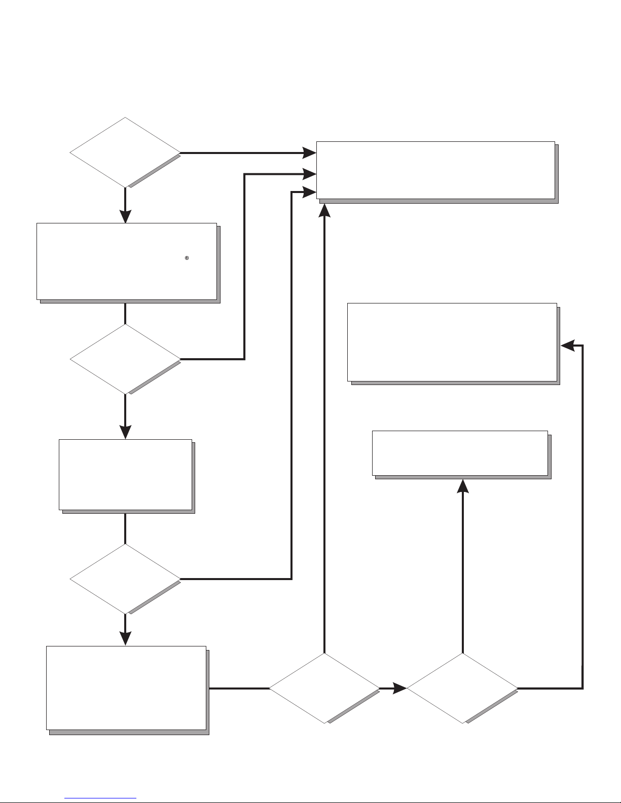
Blade Workstation Support
Is the
blade workstation
working
correctly?
No
Check all cables for loose connections
and verify that all optional devices you
installed are on the ServerProven list at
http://www.ibm.com/servers/eserver/
serverproven/compat/us/.
Is the problem
solved?
Ye s
Ye s
Register the . Go toblade workstation
http://www.ibm.com/support/mysupport/.
View information about IBM Support Line at
http://www.ibm.com/services/sl/products/
or view support telephone numbers at
http://www.ibm.com/planetwide/.
No
See the troubleshooting
information that comes with
blade workstation
the to
determine the cause of the
problem and the action to take.
Is the problem
solved?
Ye s
No
Update the firmware to the
latest level.
You can download firmware from
http://www.ibm.com/systems/
support/
.
Ye s
Is the problem
solved?
View support telephone numbers at
http://www.ibm.com/planetwide/.
Hardware
No Software
Hardware or
software problem?
Page 3

BladeCenter HC10 Ty pe 7996
Installation an d User’ s Guid e
Page 4

Note: Before using this information and the product it supports, read the general information in Appendix B, “Notices,” on page 49
and the Warranty and Support Information document on the IBM BladeCenter Documentation CD that comes with your BladeCenter
device.
First Edition (July 2007)
© Copyright International Business Machines Corporation 2007. All rights reserved.
US Government Users Restricted Rights – Use, duplication or disclosure restricted by GSA ADP Schedule Contract
with IBM Corp.
Page 5

Contents
Safety . . . . . . . . . . . . . . . . . . . . . . . . . . . .v
Chapter 1. Introduction . . . . . . . . . . . . . . . . . . . . . .1
Related documentation . . . . . . . . . . . . . . . . . . . . . .3
The IBM Documentation CD . . . . . . . . . . . . . . . . . . . .4
Hardware and software requirements . . . . . . . . . . . . . . . .4
Using the Documentation Browser . . . . . . . . . . . . . . . . .4
Notices and statements in this document . . . . . . . . . . . . . . . .5
Features and specifications . . . . . . . . . . . . . . . . . . . . .6
What your blade workstation offers . . . . . . . . . . . . . . . . . .7
Reliability, availability, and serviceability features . . . . . . . . . . . . .8
Major components of the blade workstation . . . . . . . . . . . . . . .9
Chapter 2. Power, controls, jumpers, switches, and indicators . . . . . .11
Turning on the blade workstation . . . . . . . . . . . . . . . . . .11
Turning off the blade workstation . . . . . . . . . . . . . . . . . .11
The control panel buttons and LEDs . . . . . . . . . . . . . . . . .12
System-board connectors . . . . . . . . . . . . . . . . . . . . .14
System-board switches and jumpers . . . . . . . . . . . . . . . . .14
Chapter 3. Installing optional devices . . . . . . . . . . . . . . . .15
Installation guidelines . . . . . . . . . . . . . . . . . . . . . .15
System reliability guidelines . . . . . . . . . . . . . . . . . . .15
Handling static-sensitive devices . . . . . . . . . . . . . . . . .15
Removing the blade workstation from the BladeCenter unit . . . . . . . .16
Opening the blade workstation cover . . . . . . . . . . . . . . . . .17
Removing the blade workstation bezel assembly . . . . . . . . . . . .18
Installing a SATA storage drive . . . . . . . . . . . . . . . . . . .19
Removing a SATA storage drive . . . . . . . . . . . . . . . . . .19
Installing memory modules . . . . . . . . . . . . . . . . . . . .20
Completing the installation . . . . . . . . . . . . . . . . . . . . .22
Installing the blade workstation bezel assembly . . . . . . . . . . . .22
Closing the blade workstation cover . . . . . . . . . . . . . . . .23
Installing the blade workstation in a BladeCenter unit . . . . . . . . . .24
Updating the blade workstation configuration . . . . . . . . . . . . .25
Input/output connectors and devices . . . . . . . . . . . . . . . . .26
Chapter 4. Configuring the blade workstation . . . . . . . . . . . .27
Changing the IP address . . . . . . . . . . . . . . . . . . . . .27
Changing the compression card IP address . . . . . . . . . . . . .28
Using the Configuration/Setup Utility program to change the compression
card IP address . . . . . . . . . . . . . . . . . . . . . .28
Using another computer to change the compression card IP address . . .29
Changing the thin client IP address . . . . . . . . . . . . . . . .29
Changing the blade workstation IP address for the integrated Ethernet
controller . . . . . . . . . . . . . . . . . . . . . . . . .30
Changing the IP address for the SOL function . . . . . . . . . . . .30
Establishing a session between the blade workstation and the thin client . . .30
Updating the compression card firmware . . . . . . . . . . . . . . .30
Using the Configuration/Setup Utility program . . . . . . . . . . . . .31
Configuration/Setup Utility menu choices . . . . . . . . . . . . . .31
Using passwords . . . . . . . . . . . . . . . . . . . . . . .34
Using the Boot Menu program . . . . . . . . . . . . . . . . . . .34
© Copyright IBM Corp. 2007 iii
Page 6

Enabling the Broadcom NetXtreme II Ethernet Boot Agent . . . . . . . . .35
Starting the Broadcom NetXtreme II Ethernet Boot Agent . . . . . . . . .35
Configuring the Broadcom NetXtreme Gigabit Ethernet controller . . . . . .35
Using the PXE boot agent utility program . . . . . . . . . . . . . . .36
Firmware updates . . . . . . . . . . . . . . . . . . . . . . . .36
Blade workstation Ethernet controller I/O module association . . . . . . . .37
Chapter 5. Setting up Serial over LAN for the HC10 blade workstation . . .39
Hardware and firmware requirements . . . . . . . . . . . . . . . .39
Hardware requirements . . . . . . . . . . . . . . . . . . . . .39
Software requirements . . . . . . . . . . . . . . . . . . . . .39
General configuration . . . . . . . . . . . . . . . . . . . . . .39
Configuring the BladeCenter unit . . . . . . . . . . . . . . . . .40
Enabling SOL for a blade workstation . . . . . . . . . . . . . . .40
Configuring the blade workstation BIOS for SOL . . . . . . . . . . .40
Using SOL . . . . . . . . . . . . . . . . . . . . . . . . . .41
Chapter 6. Installing the operating system . . . . . . . . . . . . . .43
Downloading installation instructions . . . . . . . . . . . . . . . . .43
Chapter 7. Solving problems . . . . . . . . . . . . . . . . . . .45
Appendix A. Getting help and technical assistance . . . . . . . . . .47
Before you call . . . . . . . . . . . . . . . . . . . . . . . . .47
Using the documentation . . . . . . . . . . . . . . . . . . . . .47
Getting help and information from the World Wide Web . . . . . . . . . .47
Software service and support . . . . . . . . . . . . . . . . . . .48
Hardware service and support . . . . . . . . . . . . . . . . . . .48
IBM Taiwan product service . . . . . . . . . . . . . . . . . . . .48
Appendix B. Notices . . . . . . . . . . . . . . . . . . . . . .49
Trademarks . . . . . . . . . . . . . . . . . . . . . . . . . .49
Important notes . . . . . . . . . . . . . . . . . . . . . . . . .50
Product recycling and disposal . . . . . . . . . . . . . . . . . . .51
Battery return program . . . . . . . . . . . . . . . . . . . . . .52
Electronic emission notices . . . . . . . . . . . . . . . . . . . .54
Federal Communications Commission (FCC) statement . . . . . . . . .54
Industry Canada Class A emission compliance statement . . . . . . . .54
Avis de conformité à la réglementation d’Industrie Canada . . . . . . . .54
Australia and New Zealand Class A statement . . . . . . . . . . . .54
United Kingdom telecommunications safety requirement . . . . . . . . .54
European Union EMC Directive conformance statement . . . . . . . . .54
Taiwanese Class A warning statement . . . . . . . . . . . . . . .55
Chinese Class A warning statement . . . . . . . . . . . . . . . .55
Japanese Voluntary Control Council for Interference (VCCI) statement . . .55
Index . . . . . . . . . . . . . . . . . . . . . . . . . . . .57
iv BladeCenter HC10 Type 7996: Installation and User’s Guide
Page 7

Safety
Before installing this product, read the Safety Information.
Antes de instalar este produto, leia as Informações de Segurança.
Pred instalací tohoto produktu si prectete prírucku bezpecnostních instrukcí.
Læs sikkerhedsforskrifterne, før du installerer dette produkt.
Lees voordat u dit product installeert eerst de veiligheidsvoorschriften.
Ennen kuin asennat tämän tuotteen, lue turvaohjeet kohdasta Safety Information.
Avant d’installer ce produit, lisez les consignes de sécurité.
Vor der Installation dieses Produkts die Sicherheitshinweise lesen.
Prima di installare questo prodotto, leggere le Informazioni sulla Sicurezza.
Les sikkerhetsinformasjonen (Safety Information) før du installerer dette produktet.
Antes de instalar este produto, leia as Informações sobre Segurança.
Antes de instalar este producto, lea la información de seguridad.
Läs säkerhetsinformationen innan du installerar den här produkten.
© Copyright IBM Corp. 2007 v
Page 8

Important:
Each caution and danger statement in this document is labeled with a
number. This number is used to cross reference an English-language
caution or danger statement with translated versions of the caution or
danger statement in the Safety Information document.
For example, if a caution statement is labeled “Statement 1”,
translations for that caution statement are in the Safety Information
document under “Statement 1.”
Be sure to read all caution and danger statements in this document
before you perform the procedures. Read any additional safety
information that comes with the blade workstation or optional device
before you install the device.
vi BladeCenter HC10 Type 7996: Installation and User’s Guide
Page 9

Statement 1:
DANGER
Electrical
current from power, telephone, and communication cables is
hazardous.
To avoid a shock hazard:
v Do not connect or disconnect any cables or perform installation,
maintenance, or reconfiguration of this product during an electrical
storm.
v Connect all power cords to a properly wired and grounded electrical
outlet.
v Connect to properly wired outlets any equipment that will be attached to
this product.
v When possible, use one hand only to connect or disconnect signal
cables.
v Never turn on any equipment when there is evidence of fire, water, or
structural damage.
v Disconnect the attached power cords, telecommunications systems,
networks, and modems before you open the device covers, unless
instructed otherwise in the installation and configuration procedures.
v Connect and disconnect cables as described in the following table when
installing, moving, or opening covers on this product or attached
devices.
To Connect: To Disconnect:
1. Turn everything OFF.
2. First, attach all cables to devices.
3. Attach signal cables to connectors.
4. Attach power cords to outlet.
1. Turn everything OFF.
2. First, remove power cords from outlet.
3. Remove signal cables from connectors.
4. Remove all cables from devices.
5. Turn device ON.
Safety vii
Page 10

Statement 2:
CAUTION:
When replacing the lithium battery, use only IBM Part Number 33F8354 or an
equivalent type battery recommended by the manufacturer. If your system has
a module containing a lithium battery, replace it only with the same module
type made by the same manufacturer. The battery contains lithium and can
explode if not properly used, handled, or disposed of.
Do not:
v Throw or immerse into water
v Heat to more than 100°C (212°F)
v Repair or disassemble
Dispose
Statement 3:
of the battery as required by local ordinances or regulations.
CAUTION:
When laser products (such as CD-ROMs, DVD drives, fiber optic devices, or
transmitters) are installed, note the following:
v Do not remove the covers. Removing the covers of the laser product could
result in exposure to hazardous laser radiation. There are no serviceable
parts inside the device.
v Use of controls or adjustments or performance of procedures other than
those specified herein might result in hazardous radiation exposure.
DANGER
laser products contain an embedded Class 3A or Class 3B laser
Some
diode. Note the following.
Laser radiation when open. Do not stare into the beam, do not view directly
with optical instruments, and avoid direct exposure to the beam.
viii BladeCenter HC10 Type 7996: Installation and User’s Guide
Page 11
Statement 5:
CAUTION:
The power control button on the device and the power switch on the power
supply do not turn off the electrical current supplied to the device. The device
also might have more than one power cord. To remove all electrical current
from the device, ensure that all power cords are disconnected from the power
source.
1 2
Statement 8:
CAUTION:
Never remove the cover on a power supply or any part that has the following
label attached.
Hazardous voltage, current, and energy levels are present inside any
component that has this label attached. There are no serviceable parts inside
these components. If you suspect a problem with one of these parts, contact
a service technician.
Safety ix
Page 12

Statement 10:
CAUTION:
Do not place any object on top of rack-mounted devices.
Statement 21:
CAUTION:
Hazardous energy is present when the blade is connected to the power
source. Always replace the blade cover before installing the blade.
x BladeCenter HC10 Type 7996: Installation and User’s Guide
Page 13

Chapter 1. Introduction
The IBM® BladeCenter® HC10 Type 7996 blade workstation is a workstation
computer in a blade structure, which is mounted in a BladeCenter unit that contains
advanced management modules. The blade workstation consolidates desktop
workstation computing resources with server-based computing solutions and
communicates with the end-user “thin client”, which consists of a communications
module, USB keyboard, monitor, mouse, and other USB end-user devices such as
a printer.
Note: Unless otherwise stated, references to the BladeCenter unit apply to all
BladeCenter, BladeCenter T, BladeCenter H, and other BladeCenter units.
This Installation and User’s Guide provides information about:
v Setting up the blade workstation
v Starting and configuring the blade workstation
v Installing optional hardware devices
v Installing the operating system
v Performing basic troubleshooting of the blade workstation
Packaged
with this document are software CDs that help you to configure
hardware, install device drivers, and install the operating system. To download the
latest device drivers or firmware, complete the following steps:
1. Go to http://www.ibm.com/systems/support/.
2. Under Product support, click BladeCenter.
3. Under Popular links, click Software and device drivers.
4. Click BladeCenter HC10 to display the matrix of downloadable files for the
BladeCenter product.
blade workstation comes with a limited warranty. For information about the
The
terms of the warranty and getting service and assistance, see the Warranty and
Support Information document for your blade workstation on the IBM BladeCenter
Documentation CD. You can obtain up-to-date information about the blade
workstation at http://www.ibm.com/systems/bladecenter/. For more information about
locating online documentation, see “Related documentation” on page 3.
If firmware and documentation updates are available, you can download them from
the IBM Web site. The blade workstation might have features that are not described
in the documentation that comes with the blade workstation, and the documentation
might be updated occasionally to include information about those features, or
technical updates might be available to provide additional information that is not
included in the blade workstation documentation. To check for updates, complete
the following steps.
Changes are made periodically to the IBM Web site. Procedures for locating
Note:
firmware and documentation might vary slightly from what is described in this
document.
1. Go to http://www.ibm.com/systems/support/.
2. Under Product support, click BladeCenter.
3. Under Popular links, click Software and device drivers for firmware updates,
or click Publications lookup for documentation updates.
© Copyright IBM Corp. 2007 1
Page 14
Record information about the blade workstation in the following table. You will need
these numbers when you register the blade workstation with IBM. You can register
the blade workstation at http://www.ibm.com/support/mysupport/.
Product name BladeCenter HC10
Machine type 7996
Model number _____________________________________________
Serial number _____________________________________________
Note: The model number and serial number are on the ID label that is behind the
control panel door on the front of the blade workstation, and on a label on
the side of the blade workstation that is visible when the blade workstation is
not in the BladeCenter unit.
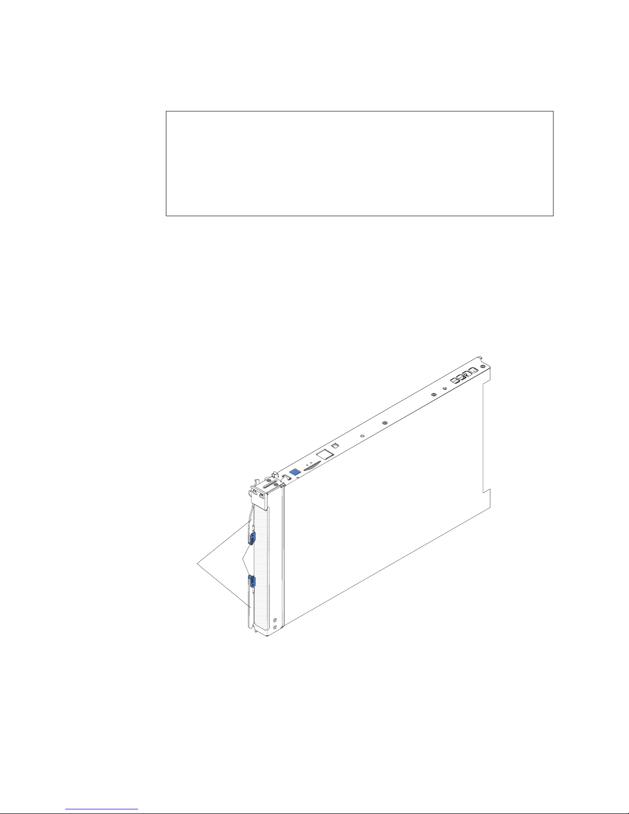
The following illustration shows the HC10 blade workstation
The illustrations in this document might differ slightly from the hardware.
Note:
Release
levers
Release
buttons
2 BladeCenter HC10 Type 7996: Installation and User’s Guide
Page 15

A set of blank labels comes with the blade workstation. When you install the blade
workstation in the BladeCenter unit, write identifying information on a label and
place the label on the BladeCenter unit bezel. See the documentation for your
BladeCenter unit for recommended label placement.
If you use bar code labels to track your blade devices, place the bar code label on
the release lever in the location that is shown in the following illustration.
Important:
Release
levers
Do not place any label anywhere else on the blade workstation or in
any way block the ventilation holes on the blade workstation.
User bar
code label
Related documentation
This Installation and User’s Guide contains general information about the blade
workstation, including how to install supported optional devices and how to
configure the blade workstation. The following documentation also comes with the
blade workstation:
v Problem Determination and Service Guide
This document is in PDF on the IBM BladeCenter Documentation CD. It contains
information to help you solve problems yourself, and it contains information for
service technicians.
v Safety Information
This document is in PDF on the IBM BladeCenter Documentation CD. It contains
translated caution and danger statements. Each caution and danger statement
that appears in the documentation has a number that you can use to locate the
corresponding statement in your language in the Safety Information document.
Chapter 1. Introduction 3
Page 16

v Warranty and Support Information
This document is in Portable Document Format (PDF) on the IBM BladeCenter
Documentation CD. It contains information about the terms of the warranty and
getting service and assistance.
Depending
on your BladeCenter product, additional documentation might be
included on the IBM BladeCenter Documentation CD. In addition to the
documentation in this library, be sure to review the IBM BladeCenter Planning and
Installation Guide for your BladeCenter unit for information to help you prepare for
system installation and configuration.
To check for updated documentation and technical updates, complete the following
steps.
Note: Changes are made periodically to the IBM Web site. The actual procedure
might vary slightly from what is described in this document.
1. Go to http://www.ibm.com/systems/support/.
2. Under Product support, click BladeCenter.
3. Under Popular links, click Publications lookup.
4. From the Product family menu, select BladeCenter HC10 and click Continue.
The IBM Documentation CD
The IBM BladeCenter Documentation CD contains documentation for your blade
workstation in Portable Document Format (PDF) and includes the IBM
Documentation Browser to help you find information quickly.
Hardware and software requirements
You can run the IBM BladeCenter Documentation CD on any system that meets the
hardware and software requirements.
The IBM BladeCenter Documentation CD requires the following minimum hardware
and software:
v Microsoft® Windows® XP, Windows 2000, or Red Hat® Linux
v 100 MHz microprocessor
v 32 MB of RAM
v Adobe® Acrobat® Reader 3.0 (or later) or xpdf, which comes with Linux operating
systems
Using the Documentation Browser
Use the Documentation Browser to browse the contents of the CD, read brief
descriptions of the documents, and view documents, using Adobe Acrobat Reader
or xpdf. The Documentation Browser automatically detects the regional settings in
the computer that you use to read the CD and displays the documents in the
language for that region (if available). If a document is not available in the language
for that region, the English-language version is displayed.
Use one of the following procedures to start the Documentation Browser:
v If Autostart is enabled, insert the CD into the CD drive. The Documentation
Browser starts automatically.
v If Autostart is disabled or is not enabled for all users, use one of the following
procedures:
4 BladeCenter HC10 Type 7996: Installation and User’s Guide
®
Page 17

– If you are using a Windows operating system, insert the CD into the CD drive
and click Start --> Run. In the Open field, type
e:\win32.bat
where e is the drive letter of the CD drive, and click OK.
– If you are using Red Hat Linux, insert the CD into the CD drive; then, run the
following command from the /mnt/cdrom directory:
sh runlinux.sh
Select your blade workstation from the Product menu. The Available Topics list
displays all the documents for your blade workstation. Some documents might be in
folders. A plus sign (+) indicates each folder or document that has additional
documents under it. Click the plus sign to display the additional documents.
When you select a document, a description of the document is displayed under
Topic Description. To select more than one document, press and hold the Ctrl key
while you select the documents. Click View Book to view the selected document or
documents in Acrobat Reader or xpdf. If you selected more than one document, all
the selected documents are opened in Acrobat Reader or xpdf.
To search all the documents, type a word or word string in the Search field and
click Search. The documents in which the word or word string appears are listed in
order of the most occurrences. Click a document to view it, and press Crtl+F to use
the Acrobat search function, or press Alt+F to use the xpdf search function within
the document.
Click Help for detailed information about using the Documentation Browser.
Notices and statements in this document
The caution and danger statements in this document are also in the multilingual
Safety Information document, which is on the IBM BladeCenter Documentation CD.
Each statement is numbered for reference to the corresponding statement in your
language in the Safety Information document.
The following notices and statements are used in this document:
v Note: These notices provide important tips, guidance, or advice.
v Important: These notices provide information or advice that might help you avoid
inconvenient or problem situations.
v Attention: These notices indicate possible damage to programs, devices, or
data. An attention notice is placed just before the instruction or situation in which
damage might occur.
v Caution: These statements indicate situations that can be potentially hazardous
to you. A caution statement is placed just before the description of a potentially
hazardous procedure step or situation.
v Danger: These statements indicate situations that can be potentially lethal or
extremely hazardous to you. A danger statement is placed just before the
description of a potentially lethal or extremely hazardous procedure step or
situation.
Chapter 1. Introduction 5
Page 18

Features and specifications
This section provides a summary of the features and specifications of the blade
workstation. Use the Configuration/Setup Utility program to determine the specific
microprocessor that is in the blade workstation.
Notes:
1. Power, cooling, removable-media drives, external ports, and advanced system
management are provided by the BladeCenter unit.
2. The operating system in the blade workstation must provide USB support for the
blade workstation to recognize and use the BladeCenter unit removable-media
drives and front-panel USB ports. The BladeCenter unit uses USB for internal
communications with these devices.
Microprocessor:
Supports one microprocessor
v Dual-core Intel® Core 2 Duo 64-bit
microprocessor
v High performance
v Low power consumption
Use the Configuration/Setup
Note:
Utility program to determine the size
of the L2 cache, speed of the
microprocessor, and speed of the
front-side bus.
Memory:
v Dual channel 800/667/533 MHz
DDR2 with four dual inline memory
module (DIMM) connectors
v Minimum: 1 GB; maximum: 8 GB
v Type: Two-way interleaved,
unbuffered non-ECC DDR2,
PC2-5300, SDRAM DIMMs only
v Size: 512 MB, 1 GB, and 2 GB, in
pairs
Drives:
v One internal small-form-factor
pluggable (SFP), S ATA International
Organization (SATA-IO) storage
drive
v 60 GB or larger
v 5400 rpm (if hard disk drive) or
faster
Integrated functions:
v Q965 Express chip set with ICH8
v Broadcom Gigabit Ethernet
controller with TCP/IP offload
engine (TOE)
v Local service processor:
Baseboard management controller
(BMC) with Intelligent Platform
Management Interface (IPMI)
firmware and Serial over LAN
(SOL)
v Local service processor (BMC)
v RS-485 interface for
communication with the
management module
v Automatic blade workstation
restart
v Four USB buses for
communication with keyboard,
mouse, and removable media
drives
Keyboard/video/mouse:
v One of the following
high-resolution video controllers
(graphics cards), depending on
the blade workstation model:
– NVIDIA Quadro FX 1600M (3D)
– NVIDIA Quadro NVS 120M
Support for dual keyboard, video,
v
and mouse (BladeCenter KVM
and thin client KVM)
v Graphics and I/O Transmission
Adapter (compression card) for
communication with thin client
(2D)
Electrical Input:
12 V dc
Environment:
v Air temperature:
– Blade workstation on: 10° to 35°C
(50° to 95°F). Altitude: 0 to 914 m
(2998.69 ft)
– Blade workstation on: 10° to 32°C
(50° to 95°F). Altitude: 914 m to
2134 m (2998.69 ft to 7000 ft)
– Blade workstation off: -40° to
60°C (-40° to 140°F)
v
Humidity:
– Blade workstation on: 8% to 80%
– Blade workstation off: 5% to 80%
Size:
v Height: 24.5 cm (9.7 inches)
v Depth: 44.6 cm (17.6 inches)
v Width: 2.9 cm (1.14 inches)
v Maximum weight: 4.29 kg (9.46 lb)
6 BladeCenter HC10 Type 7996: Installation and User’s Guide
Page 19

What your blade workstation offers
The design of the blade workstation takes advantage of advancements in memory
management and data storage. The blade workstation uses the following features
and technologies:
v Impressive performance using the latest microprocessor technology
The blade workstation supports one dual-core Intel Core 2 Duo microprocessor.
Because the microprocessor is dual-core, it provides enhanced performance and
symmetric multiprocessing (SMP) capability . You might have to upgrade the
operating system to support SMP. To use SMP, you must configure it to enable
the dual-core function.
v Large system-memory capacity
The memory bus in the blade workstation supports up to 8 GB of system
memory. The memory controller provides support for up to four industry-standard
240-pin double-data-rate (DDR2), PC2-5300, synchronous dynamic
random-access memory (SDRAM) DIMMs. For the most current list of supported
DIMMs, see http://www.ibm.com/servers/eserver/serverproven/compat/us/.
v Included thin client support
The remote user communicates with the blade workstation operating system and
all application programs through a thin client, which consists of a supported
communication module, USB keyboard, monitor, mouse, and other USB devices
such as a printer. The Graphics and I/O Transmission Adapter in the blade
workstation provides a high-speed user interface to the user location through a
dedicated connection over an Ethernet network to the communication module of
the thin client. The user interface has the same function and appearance as a
workstation at the user location would provide.
v High-speed high-resolution 2D or 3D graphics capability
Depending on the graphics controller that is installed, the blade workstation
supports either 2D or 3D high-resolution graphics when it communicates with the
thin client. The Graphics and I/O Transmission Adapter that is also in the blade
workstation compresses the video stream and rapidly transmits the video, audio,
and USB signals over the Ethernet network to the thin client communication
module. The thin client decompresses the video and presents it to the remote
user. For simplicity, the Graphics and I/O Transmission Adapter is referred to in
the HC10 blade workstation documentation as a compression card.
v Ethernet TCP/IP offload engine (TOE) support
The Ethernet controller in the blade workstation supports TOE, which is a
technology that offloads the TCP/IP flow from the microprocessor and I/O
subsystem to increase the speed of the TCP/IP flow. When an operating system
that supports TOE is running on the blade workstation and TOE is enabled, the
blade workstation supports TOE operation. See the operating-system
documentation for information about enabling TOE.
v Storage drive support
The blade workstation supports one small-form-factor SATA storage drive, such
as a hard disk drive.
v PCI Express
PCI Express is a fully serial interface that is used for high-speed connections to
the NVIDIA graphics controller, the compression card, and the integrated
Ethernet controller.
Chapter 1. Introduction 7
Page 20

v IBM Director
IBM Director is a workgroup-hardware-management tool that you can use to
centrally manage servers and blade workstations. For more information, see the
IBM Director documentation on the IBM Director CD.
Reliability, availability, and serviceability features
Three of the most important features in blade workstation design are reliability,
availability, and serviceability (RAS). These RAS features help to ensure the
integrity of the data that is stored in the blade workstation, the availability of the
blade workstation when you need it, and the ease with which you can diagnose and
correct problems.
The blade workstation has the following RAS features:
v Advanced Configuration and Power Interface (ACPI)
v Automatic error retry or recovery
v Automatic restart
v Built-in monitoring for temperature and voltage
v Upgradeable basic input/output system (BIOS) code
v Support center 24 hours per day, 7 days a week
v Diagnostic support of the Ethernet controller
v Error codes and messages
v Power-on self-test (POST)
v Processor serial number access
v ROM resident diagnostics
v Service processor that communicates with the management module to enable
remote blade workstation management
v SDRAM with serial presence detect (SPD) and vital product data (VPD)
v System error logging
v VPD (includes information stored in nonvolatile memory for easier remote
viewing)
v Wake on LAN® capability
1
1. Service availability will vary by country. Response time will vary depending on the number and nature of incoming calls.
8 BladeCenter HC10 Type 7996: Installation and User’s Guide
Page 21
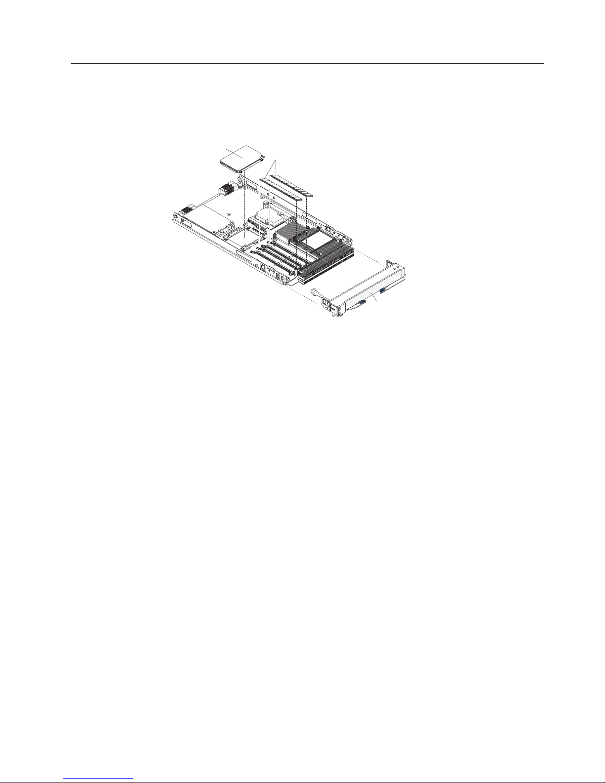
Major components of the blade workstation
You must remove the blade workstation from the BladeCenter unit and remove the
cover to see the components. The following illustration shows the major
components of a BladeCenter HC10 Type 7996 blade workstation.
SATA storage
drive
DIMMs
Bezel
Chapter 1. Introduction 9
Page 22

10 BladeCenter HC10 Type 7996: Installation and User’s Guide
Page 23

Chapter 2. Power, controls, jumpers, switches, and indicators
This chapter describes the power features, how to turn on and turn off the blade
workstation, and what the controls and indicators mean. This chapter also identifies
the system board jumpers and switches.
Turning on the blade workstation
After you connect the blade workstation to power through the BladeCenter unit, the
blade workstation can start in any of the following ways:
v You can press the power-control button on the front of the blade workstation
(behind the control panel door, see “The control panel buttons and LEDs” on
page 12) to start the blade workstation.
Notes:
1. Wait until the power-on LED on the blade workstation flashes slowly before
you press the blade workstation power-control button. While the service
processor in the management module is initializing, the power-on LED does
not flash, and the power-control button on the blade workstation does not
respond.
2. While the blade workstation is starting, the power-on LED on the front of the
blade workstation is lit. See “The control panel buttons and LEDs” on page
12 for the power-on LED states.
If a power failure occurs, the BladeCenter unit and then the blade workstation
v
can start automatically when power is restored, if the blade workstation is
configured through the management module to do so.
v You can turn on the blade workstation remotely by using the management
module.
v If the blade workstation is connected to power (the power-on LED is flashing
slowly), the operating system supports the Wake on LAN feature, and the Wake
on LAN feature has not been disabled through the management module, the
Wake on LAN feature can turn on the blade workstation.
v The thin client can turn on the blade workstation remotely.
Turning off the blade workstation
When you turn off the blade workstation, it is still connected to power through the
BladeCenter unit. The blade workstation can respond to requests from the service
processor, such as a remote request to turn on the blade workstation. To remove all
power from the blade workstation, you must remove it from the BladeCenter unit.
Shut down the operating system before you turn off the blade workstation. See the
operating-system documentation for information about shutting down the operating
system.
The blade workstation can be turned off in any of the following ways:
v You can press the power-control button on the blade workstation (behind the
control panel door, see “The control panel buttons and LEDs” on page 12). This
starts an orderly shutdown of the operating system, if this feature is supported by
the operating system.
Note: After you turn off the blade workstation, wait at least 5 seconds before you
© Copyright IBM Corp. 2007 11
press the power-control button to turn on the blade workstation again.
Page 24

v If the operating system stops functioning, you can press and hold the
power-control button for more than 4 seconds to turn off the blade workstation.
v The management module can turn off the blade workstation.
v The thin client can turn off the blade workstation.
The control panel buttons and LEDs
This section describes the controls and LEDs on the blade workstation.
Note: The control panel door is shown in the closed (normal) position in the
following illustration. To access the power-control button, you must open the
control panel door.
Media-tray
select button
KVM
select button
Activity LED
Location LED
Information LED
Blade-error LED
Power-control button
Power-on LED
Sleep-mode LED
KVM select button: Press this button to associate the shared BladeCenter unit
keyboard, video, and mouse (KVM) with the blade workstation. The LED on this
button flashes while the request is being processed and then is lit when the
ownership of the keyboard, video, and mouse has been transferred to the blade
workstation. It can take approximately 20 seconds to switch the keyboard, video,
and mouse control from one blade workstation to another.
Using a keyboard that is directly attached to the management module, you can also
press keyboard keys in the following sequence to switch KVM control between
blade workstations:
NumLock NumLock bay_number Enter
(bay_number is the two-digit number of the blade bay in which the blade
workstation is installed.)
Only USB keyboard, video, and mouse are supported. The operating system in the
blade workstation must provide USB support for the blade workstation to recognize
and use the keyboard and mouse. When you are not running an operating system
that has USB device drivers, such as in the following situations, the keyboard
responds very slowly:
v Running the blade workstation integrated diagnostics
v Running a BIOS update diskette on a blade workstation
v Updating the diagnostics on a blade workstation
v Running the Broadcom firmware CD for a blade workstation
12 BladeCenter HC10 Type 7996: Installation and User’s Guide
Page 25

If there is no response when you press the KVM select button, you can use the
management-module Web interface to determine whether local control has been
disabled on the blade workstation.
Media-tray select button: Press this button to associate the shared BladeCenter
unit media tray (removable-media drives and front-panel USB ports) with the blade
workstation. The LED on the button flashes while the request is being processed,
and then is lit when the ownership of the media tray has been transferred to the
blade workstation. It can take approximately 20 seconds for the operating system in
the blade workstation to recognize the media tray.
If there is no response when you press the media-tray select button, you can use
the management-module Web interface to determine whether local control has been
disabled on the blade workstation.
The operating system in the blade workstation must provide USB support for the
blade workstation to recognize and use the removable-media drives and USB ports.
The BladeCenter unit uses USB for internal communication with these devices.
Activity LED: When this green LED is lit, it indicates that there is activity on the
hard disk drive, flash drive, or network.
Location LED: The system administrator can remotely light this blue LED to aid in
visually locating the blade workstation. When this LED is lit, the location LED on the
BladeCenter unit is lit also. The location LED can be turned off through the
management-module Web interface or through IBM Director Console.
Information LED: When this amber LED is lit, it indicates that information about a
system error for the blade workstation has been placed in the system-error log. The
information LED can be turned off through the management-module Web interface
or through IBM Director Console.
Blade-error LED: When this amber LED is lit, it indicates that a system error has
occurred in the blade workstation. The blade-error LED turns off only after the error
is corrected.
Power-control button: This button is behind the control panel door. Press this
button to turn on or turn off the blade workstation.
Note: The power-control button has effect only if local power control is enabled for
the blade workstation. Local power control is enabled and disabled through
the management-module Web interface.
Power-on LED: This green LED indicates the power status of the blade workstation
in the following manner:
v Flashing rapidly: The service processor (BMC) on the blade workstation is
handshaking with the management module.
v Flashing slowly: The blade workstation has power but is not turned on.
v Lit continuously: The blade workstation has power and is turned on.
Sleep-mode
is in Sleep mode. The blade workstation can be put in the Sleep or Hibernate mode
by the operating system or by the thin client. The blade workstation can be
awakened through the management-module Web interface, through IBM Director
Console, or by the thin client.
LED: When this green LED is lit, it indicates that the blade workstation
Chapter 2. Power, controls, jumpers, switches, and indicators 13
Page 26

System-board connectors
The following illustration shows the system-board components and connectors,
including connectors for user-installable optional devices, in the blade workstation.
Battery
Video controller
Microprocessor
Compression card
SATA storage drive
System-board switches and jumpers
The following illustration shows the location of the clear CMOS button and the
jumper that is used to recover BIOS. See the information about how and when to
use the switches, jumpers, or buttons in the Problem Determination and Service
Guide on the IBM BladeCenter Documentation CD.
BIOS recovery jumper
DIMM1
DIMM2
DIMM3
DIMM4
Clear CMOS button
14 BladeCenter HC10 Type 7996: Installation and User’s Guide
Page 27

Chapter 3. Installing optional devices
This chapter provides instructions for installing optional hardware devices in the
blade workstation. Instructions for removing some optional devices are provided in
case you have to remove one device to install another.
Installation guidelines
Before you install optional devices in the blade workstation, read the following
information:
v Read the safety information that begins on page v and the guidelines in
“Handling static-sensitive devices.” This information will help you work safely.
v Back up all important data before you make changes to disk drives.
v Before you remove a hot-swap blade workstation from the BladeCenter unit, you
must shut down the operating system and turn off the blade workstation. You do
not have to shut down the BladeCenter unit itself.
v Blue on a component indicates touch points, where you can grip the component
to remove it from or install it in the blade workstation, or open or close a latch.
v Orange on a component or an orange label on or near a component indicates
that the component can be hot-swapped, which means that you can remove or
install the component while the BladeCenter unit is running. (Orange can also
indicate touch points on hot-swap components.) See the instructions for removing
or installing a specific hot-swap component for any additional procedures that
you might have to perform before you remove or install the component.
v For a list of supported optional devices for the blade workstation, go to
http://www.ibm.com/servers/eserver/serverproven/compat/us/.
System reliability guidelines
To help ensure proper cooling and system reliability, do not operate the
BladeCenter unit without a blade device or filler blade installed in each blade bay.
See the documentation for your BladeCenter unit for additional information.
Handling static-sensitive devices
Attention: Static electricity can damage the blade workstation and other
electronic devices. To avoid damage, keep static-sensitive devices in their
static-protective packages until you are ready to install them.
To reduce the possibility of damage from electrostatic discharge, observe the
following precautions:
v When you work on the BladeCenter T unit, use an electrostatic discharge (ESD)
wrist strap, especially when you will be handling modules, optional devices, or
blade workstations. To work correctly, the wrist strap must have a good contact at
both ends (touching your skin at one end and firmly connected to the ESD
connector on the front or back of the BladeCenter T unit).
v Limit your movement. Movement can cause static electricity to build up around
you.
v Handle the device carefully, holding it by its edges or its frame.
v Do not touch solder joints, pins, or exposed circuitry.
v Do not leave the device where others can handle and damage it.
© Copyright IBM Corp. 2007 15
Page 28

v While the device is still in its static-protective package, touch it to an unpainted
metal part of the BladeCenter unit or any unpainted metal surface on any other
grounded rack component in the rack in which you are installing the device for at
least 2 seconds. This drains static electricity from the package and from your
body.
v Remove the device from its package and install it directly into the blade
workstation without setting it down. If it is necessary to set down the device, put
it back into its static-protective package. Do not place the device on the blade
workstation cover or on a metal surface.
v Take additional care when you handle devices during cold weather. Heating
reduces indoor humidity and increases static electricity.
Removing the blade workstation from the BladeCenter unit
The following illustration shows how to remove the blade workstation from a typical
BladeCenter unit.
Attention:
v To maintain proper system cooling, do not operate the BladeCenter unit without a
blade workstation, expansion unit, or filler blade installed in each blade bay.
v When you remove the blade workstation, note the bay number. Reinstalling a
blade workstation into a different bay than the one it was removed from can have
unintended consequences. Some configuration information and update options
are established according to bay number; if you reinstall the blade workstation
into a different bay, you might have to reconfigure the blade workstation.
remove the blade workstation, complete the following steps:
To
1. If the blade workstation is operating, shut down the operating system; then,
press the power-control button (behind the blade workstation control panel door)
to turn off the blade workstation (see “Turning off the blade workstation” on
page 11 for more information).
Attention: Wait at least 30 seconds, until the hard disk drives stop spinning,
before you proceed to the next step.
2. Open the two release levers as shown in the illustration. The blade workstation
moves out of the bay approximately 0.6 cm (0.25 inch).
3. Pull the blade workstation out of the bay. Spring-loaded doors farther back in
the bay move into place to cover the bay temporarily.
4. Place either a filler blade or another blade in the bay within 1 minute. The
recessed spring-loaded doors will move out of the way as you insert the blade
or filler blade.
16 BladeCenter HC10 Type 7996: Installation and User’s Guide
Page 29

Opening the blade workstation cover
The following illustration shows how to open the cover on a blade workstation.
Cover
pins
Blade-cover
To open the blade workstation cover, complete the following steps:
1. Read the safety information that begins on page v and “Installation guidelines”
on page 15.
2. If the blade workstation is installed in a BladeCenter unit, remove it (see
“Removing the blade workstation from the BladeCenter unit” on page 16 for
instructions).
3. Carefully lay the blade workstation on a flat, static-protective surface, with the
cover side up.
4. Press the blade-cover release on each side of the blade workstation and lift the
cover open, as shown in the illustration.
5. Lay the cover flat, or lift it from the blade workstation and store it for future use.
release
Blade-cover
release
Statement 21:
CAUTION:
Hazardous energy is present when the blade is connected to the power
source. Always replace the blade cover before installing the blade.
Chapter 3. Installing optional devices 17
Page 30

Removing the blade workstation bezel assembly
To install certain optional devices, you might choose to first remove the blade
workstation bezel assembly. The following illustration shows how to remove the
bezel assembly.
Bezel-assembly
release
Bezel-assembly
release
Bezel
Control-panel cable
To remove the blade workstation bezel assembly, complete the following steps:
1. Read the safety information that begins on page v and “Installation guidelines”
on page 15.
2. Open the blade workstation cover (see “Opening the blade workstation cover”
on page 17 for instructions).
3. Disconnect the control-panel cable from the control-panel connector.
4. Press the bezel-assembly release and pull the bezel assembly away from the
blade workstation approximately 1.2 cm (0.5 inch).
5. Pull the bezel assembly completely away from the blade workstation.
6. Store the bezel assembly in a safe place.
Control-panel connector
18 BladeCenter HC10 Type 7996: Installation and User’s Guide
Page 31

Installing a SATA storage drive
The blade workstation supports one small-form-factor SATA storage drive, such as a
hard disk drive. The blade workstation comes with an installed SATA drive. If you
have to replace or upgrade the SATA storage drive, see the instructions in
“Removing a SATA storage drive,” and then complete the steps in this section.
See http://www.ibm.com/servers/eserver/serverproven/compat/us/ for a list of
supported SATA storage drives for the blade workstation.
The following illustration shows how to install a SATA storage drive.
Storage drive
Storage drive
release lever
To install a SATA storage drive, complete the following steps:
1. Read the safety information that begins on page v and “Installation guidelines”
on page 15.
2. Shut down the operating system, turn off the blade workstation, and remove the
blade workstation from the BladeCenter unit. See “Removing the blade
workstation from the BladeCenter unit” on page 16 for instructions.
3. Carefully lay the blade workstation on a flat, static-protective surface.
4. Open the blade workstation cover (see “Opening the blade workstation cover”
on page 17 for instructions).
5. Locate the SATA connector.
Attention: Do not press on the top of the drive. Pressing the top might
damage the drive.
6. Orient the drive so that the connector on the drive aligns with the S ATA
connector on the system board.
7. Put the drive into the tray and push it, from the rear edge of the drive, into the
connector until the drive moves past the lever at the back of the tray.
If you have other devices to install or remove, do so now; otherwise, go to
“Completing the installation” on page 22.
Removing a SATA storage drive
To remove a SATA storage drive, complete the following steps:
1. Read the safety information that begins on page v and “Installation guidelines”
on page 15.
2. Shut down the operating system, turn off the blade workstation, and remove the
blade workstation from the BladeCenter unit. See “Removing the blade
workstation from the BladeCenter unit” on page 16 for instructions.
Chapter 3. Installing optional devices 19
Page 32

3. Carefully lay the blade workstation on a flat, static-protective surface.
4. Open the blade workstation cover (see “Opening the blade workstation cover”
on page 17 for instructions).
5. Locate the SATA storage drive in the SATA connector. Move the blue lever at
the side of the storage drive tray away from the drive to release the drive.
6. From the rear edge of the drive, slide the drive out of the S ATA connector.
Installing memory modules
The following notes describe the types of dual inline memory modules (DIMMs) that
the blade workstation supports and other information that you must consider when
you install DIMMs:
v The system board contains four DIMM connectors and supports two-way memory
interleaving.
v The DIMMs that are available for the blade workstation are 512 MB, 1 GB, and 2
GB. Depending on the memory configuration that is set in the
Configuration/Setup Utility program, the blade workstation can support a
minimum of 1 GB and a maximum of 8 GB of system memory.
v The blade workstation comes with two DIMMs, in the DIMM 1 and DIMM 3
connectors.
v When you install additional DIMMs, you must install them as a pair, in DIMM
connectors 2 and 4.
v Install the DIMMs in the following order:
Pair DIMM connectors
First 1 and 3
Second 2 and 4
v Both DIMMs in a pair must be of the same size, speed, type, technology, and
physical design. You can mix compatible DIMMs from different manufacturers.
v The second pair of DIMMs does not have to be of the same size, speed, type,
technology, and physical design as the first pair.
v Install only 1.8 V, 240-pin, DDR2, PC2-5300 SDRAM with non-ECC DIMMs that
are compatible with the latest PC2-5300 SDRAM DIMM specification, which is
available from http://www.jedec.org/. For a current list of supported DIMMs for the
blade workstation, see http://www.ibm.com/servers/eserver/serverproven/compat/
us/.
v Installing or removing DIMMs changes the configuration of the blade workstation.
When you restart the blade workstation, a message indicates that the memory
configuration has changed. Start the Configuration/Setup Utility program and
select Save Settings. See “Configuration/Setup Utility menu choices” on page 31
for more information.
To install a DIMM, complete the following steps:
1. Read the safety information that begins on page v and “Installation guidelines”
on page 15.
2. Read the documentation that comes with the DIMMs.
3. Shut down the operating system, turn off the blade workstation, and remove the
blade workstation from the BladeCenter unit. See “Removing the blade
workstation from the BladeCenter unit” on page 16 for instructions.
4. Carefully lay the blade workstation on a flat, static-protective surface.
20 BladeCenter HC10 Type 7996: Installation and User’s Guide
Page 33

5. Open the blade workstation cover (see “Opening the blade workstation cover”
on page 17 for instructions).
DIMM 2
DIMM 4
DIMM 1
DIMM 2 connector
DIMM 3
DIMM 4 connector
6. Locate the DIMM connectors on the system board (see the illustration), and
determine the connectors into which you will install the DIMMs.
7. Touch the static-protective package that contains the DIMM optional device to
any unpainted metal surface on the BladeCenter unit or any unpainted metal
surface on any other grounded rack component in the rack that you are
installing the DIMM in for at least 2 seconds; then, remove the DIMM from its
package.
8. Complete the following steps for each DIMM that you install:
a. Open the retaining clips on the DIMM connector.
b. Turn the DIMM so that the DIMM keys align correctly with the connector on
the system board.
Attention: To avoid breaking the retaining clips or damaging the DIMM
connectors, handle the clips gently.
c. Insert the DIMM by pressing the DIMM along the guides into the connector.
Make sure that the retaining clips snap into the closed position.
Important: If there is a gap between the DIMM and the retaining clips, the
DIMM has not been correctly installed. Open the retaining clips and remove
the DIMM; then, reinsert the DIMM.
If you have other devices to install or remove, do so now; otherwise, go to
“Completing the installation” on page 22.
Chapter 3. Installing optional devices 21
Page 34

Completing the installation
To complete the installation, complete the following tasks. Instructions for each task
are in the following sections.
1. Reinstall the blade workstation bezel assembly, if you removed it (see “Installing
the blade workstation bezel assembly” for information on installing the bezel
assembly).
2. Close the blade workstation cover (see “Closing the blade workstation cover” on
page 23).
Statement 21:
CAUTION:
Hazardous energy is present when the blade is connected to the power
source. Always replace the blade cover before installing the blade.
3. Reinstall the blade workstation into the BladeCenter unit (see “Installing the
blade workstation in a BladeCenter unit” on page 24).
4. Turn on the blade workstation (see “Turning on the blade workstation” on page
11).
5. For certain optional devices, run the blade workstation Configuration/Setup
Utility program (see “Updating the blade workstation configuration” on page 25).
Note: If you have just connected the power cords of the BladeCenter unit to
electrical outlets, you must wait until the power-on LED on the blade
workstation flashes slowly before you press the power-control button.
Installing the blade workstation bezel assembly
The following illustration shows how to install the bezel assembly.
Bezel-assembly
release
Bezel-assembly
release
Bezel
Control-panel cable
To install the blade workstation bezel assembly, complete the following steps:
1. Read the safety information that begins on page v and “Installation guidelines”
on page 15.
2. Connect the control-panel cable to the control-panel connector on the system
board.
3. Carefully slide the bezel assembly onto the blade workstation until it clicks into
place.
Control-panel connector
22 BladeCenter HC10 Type 7996: Installation and User’s Guide
Page 35

Closing the blade workstation cover
Important: The blade workstation cannot be inserted into the BladeCenter unit until
the cover is installed and closed. Do not attempt to override this protection.
The following illustration shows how to close the blade workstation cover.
Cover
pins
Blade-cover
release
Blade-cover
release
To close the blade workstation cover, complete the following steps:
1. Read the safety information that begins on page v and “Installation guidelines”
on page 15.
2. If you removed the blade bezel assembly, replace it now (see “Installing the
blade workstation bezel assembly” on page 22 for instructions).
3. Make sure that all components are installed and seated correctly and that you
have not left loose tools or parts inside the blade workstation.
4. Make sure that the control-panel cable and all other cables are placed so that
the cover does not crimp or pinch them.
5. Lower the cover so that the slots at the rear slide down onto the pins at the rear
of the blade workstation, as shown in the illustration.
6. Pivot the cover to the closed position, as shown in the illustration, until it clicks
into place.
Chapter 3. Installing optional devices 23
Page 36

Installing the blade workstation in a BladeCenter unit
The following illustration shows how to install the blade workstation into a typical
BladeCenter unit.
To install a blade workstation in a BladeCenter unit, complete the following steps.
Statement 21:
CAUTION:
Hazardous energy is present when the blade is connected to the power
source. Always replace the blade cover before installing the blade.
1. Read the safety information that begins on page v and “Installation guidelines”
on page 15 through “Handling static-sensitive devices” on page 15.
2. If you have not done so already, install any optional devices that you want,
such as DIMMs, in the blade workstation.
3. Select the bay for the blade workstation.
Notes:
a. When any blade workstation is in blade bay 7 through 14 (in a BladeCenter
unit) or in blade bays 5 through 8 (in a BladeCenter T unit), power modules
must be present in all four power-module bays.
b. To help ensure proper cooling, performance, and system reliability, make
sure that each of the blade bays on the front of the BladeCenter unit has a
blade workstation or filler blade installed. Do not operate a BladeCenter
unit for more than 1 minute or a BladeCenter T unit for more than 20
minutes without a blade workstation or filler blade installed in each blade
bay.
4. Make sure that the release levers on the blade workstation are in the open
position (perpendicular to the blade workstation).
5. Slide the blade workstation into the blade bay until it stops. The spring-loaded
doors, farther back in the bay, that cover the bay opening move out of the way
as you insert the blade workstation.
6. Push the release levers on the front of the blade workstation to the closed
position.
7. Turn on the blade workstation (see “Turning on the blade workstation” on page
11 for instructions).
24 BladeCenter HC10 Type 7996: Installation and User’s Guide
Page 37

8. Make sure that the power-on LED on the blade workstation control panel is lit
continuously, indicating that the blade workstation is receiving power and is
turned on.
9. (Optional) Write identifying information on one of the user labels that come
with the blade workstations and place the label on a BladeCenter unit bezel.
See the illustrations in the documentation that comes with the BladeCenter unit
for information about the label placement.
Important: Do not place the label on the blade workstation or in any way block
the ventilation holes on the blade workstation.
10. (Optional) If you use bar codes to track your blade devices, place the bar code
label in the label area on the blade workstation release lever. See the
illustrations on page 3 for information about the label placement.
Important: Do not place the label anywhere else on the blade workstation or
in any way block the ventilation holes on the blade workstation.
11. If you have other blade devices to install, do so now.
Note: Reinstall the bezel assembly on the BladeCenter T unit after you have
finished installing the blade workstations (see the BladeCenter T Types
8720 and 8730 Installation and User’s Guide for detailed instructions for
reinstalling the bezel assembly). However, if you installed an optional
device on another blade device in the BladeCenter unit, such as a PCI
expansion card with PCI adapters that require cables, you will not be
able to install the bezel assembly, which contains an air filter for a
BladeCenter T unit. If you require an air filter, a filter must then be
provided on the rack.
If you reinstall a blade device that you removed, you must install it in the same
blade bay from which you removed it. Some blade device configuration information
and update options are established according to bay number. Reinstalling a blade
device into a different blade bay from the one from which it was removed might
have unintended consequences, and you might have to reconfigure the blade
device.
If this is the initial installation of the blade workstation in the BladeCenter unit, you
must configure the blade workstation through the Configuration/Setup Utility
program. If an operating system is not preinstalled in the blade workstation, you
must install the blade workstation operating system. See “Updating the blade
workstation configuration” and Chapter 6, “Installing the operating system,” on page
43 for details.
Updating the blade workstation configuration
When the blade workstation starts for the first time after you add or remove an
internal optional device or an external SATA device, you might receive a message
that the configuration has changed. The Configuration/Setup Utility program
automatically starts so that you can save the new configuration settings. See “Using
the Configuration/Setup Utility program” on page 31 for more information.
Some optional devices have device drivers that you must install. For information
about installing device drivers, see the documentation that comes with each device.
The blade workstation comes with one microprocessor. Because the microprocessor
is dual-core, the blade workstation can operate as a symmetric multiprocessing
(SMP) computer. Yo u might have to upgrade the operating system to support SMP,
Chapter 3. Installing optional devices 25
Page 38

and you must configure SMP to enable dual core. See Chapter 6, “Installing the
operating system,” on page 43 and your operating-system documentation for
additional information.
Input/output connectors and devices
The input/output connectors that are available to the blade workstation for external
devices are supplied by the BladeCenter unit. See the documentation that comes
with the BladeCenter unit for information about the input/output connectors.
The blade workstation has two selection buttons on the control panel: the
media-tray select button and the keyboard/video/mouse (KVM) select button. See
“The control panel buttons and LEDs” on page 12 for information about these
buttons and their functions.
The Ethernet controller in the blade workstation communicates with the network
through an Ethernet-compatible I/O module (the default is I/O module 1) on the
BladeCenter unit. Network signals to and from the blade workstation are
automatically routed to the I/O module through circuitry in the blade workstation and
the BladeCenter unit.
The compression card in the blade workstation, which provides the user interface to
the thin client, communicates with the remote thin client through an
Ethernet-compatible I/O module in I/O bay 2 of the BladeCenter unit.
Note: When you use the BladeCenter management-module Web interface to view
the hardware VPD information for the blade workstation, the compression
card is listed as an expansion card.
26 BladeCenter HC10 Type 7996: Installation and User’s Guide
Page 39

Chapter 4. Configuring the blade workstation
Important: Configure the IP address of the blade workstation compression card
and the thin client first, so that they can communicate with each other. Then, you
can perform other configuration tasks. To configure the compression card IP
address, follow the instructions in “Changing the IP address.”
The following configuration programs come with the blade workstation:
v Configuration/Setup Utility program
The Configuration/Setup Utility program is part of the basic input/output system
(BIOS). Use it to change system settings, such as interrupt requests (IRQ), date
and time, and passwords. See “Using the Configuration/Setup Utility program” on
page 31 for more information.
v Boot Menu program
The Boot Menu program is part of the BIOS. Use it to override the startup
sequence that is set in the Configuration/Setup Utility program and temporarily
assign a device to be first in the startup sequence. For information about how to
start the Boot Menu, see “Using the Boot Menu program” on page 34.
v Broadcom NetXtreme II Ethernet Boot Agent
The Broadcom NetXtreme II Ethernet Boot Agent is part of the BIOS. Yo u can
use it to configure the Ethernet boot options, such as the boot protocol to use,
the link speed, and the VLAN mode and ID. Enable and disable the Broadcom
NetXtreme II Ethernet Boot Agent from the Configuration/Setup Utility program.
For information, see “Enabling the Broadcom NetXtreme II Ethernet Boot Agent”
on page 35.
information about configuring the integrated Ethernet controller, see
For
“Configuring the Broadcom NetXtreme Gigabit Ethernet controller” on page 35.
For information about setting up the network configuration for remote management,
such as with the IBM Director products, see the IBM BladeCenter Planning and
Installation Guide for your BladeCenter unit. You can obtain the planning guides
from http://www.ibm.com/systems/support/.
Changing the IP address
The blade workstation contains three IP addresses:
v The IP address on the compression card, for communication between the
compression card and the thin client
v The IP address for the blade workstation integrated Ethernet controller, for
workstation communication on the network
v The IP address for the Serial over LAN (SOL) function of the blade workstation
BMC
remote thin client also has an IP address, for communication with the blade
The
workstation compression card. See the following sections for information about
changing each IP address:
v “Changing the compression card IP address” on page 28
v “Changing the thin client IP address” on page 29
v “Changing the blade workstation IP address for the integrated Ethernet controller”
on page 30
v “Changing the IP address for the SOL function” on page 30
© Copyright IBM Corp. 2007 27
Page 40

Changing the compression card IP address
The IP address and communications firmware that is stored on the compression
card in the blade workstation is used for communication with the thin client only.
All blade workstation compression cards have Dynamic Host Configuration Protocol
(DHCP) enabled by default. If you are using DHCP on the network, DHCP assigns
an IP address dynamically. If you configure the compression card to disable DHCP,
the compression card uses the static network configuration. The compression card
has the following default static network configuration:
IP address: 192.168.100.1
Subnet: 255.255.255.0
Gateway: 192.168.100.254
To avoid network conflicts, you must use DHCP or change the default static IP
address to a unique IP address for each blade workstation compression card. You
also must create a unique IP address for each thin client.
Important:
v Whether you use DHCP or use the static IP address, set the IP address of only
one compression card at a time, with only one new blade workstation on the
network at a time.
v I/O modules 1 and 2 on the BladeCenter unit must be Ethernet-capable.
DHCP is enabled, the compression card automatically obtains its IP address from
If
a DHCP server. The card then attempts to discover a DNS server, so that it can
register itself with a connection manager or connection broker for connection to the
thin client. For a description of the registration process, see the documentation that
comes with the connection broker software that you purchased.
The compression card DNS Discovery Prefix factory setting is ws-broker.
Note:
If DHCP is not enabled, you can change the compression card static IP address in
either of two ways:
v Using the blade workstation Configuration/Setup Utility program. See “Using the
Configuration/Setup Utility program to change the compression card IP address”.
v Using a computer, such as a notebook computer, on the same subnet and
gateway as the blade workstation, and logging in to the blade workstation. Yo u
can connect the computer to the network or directly to the Ethernet-capable I/O
module 2. See “Using another computer to change the compression card IP
address” on page 29.
Using the Configuration/Setup Utility program to change the
compression card IP address
To change the blade workstation compression card IP address through the
Configuration/Setup Utility program, complete the following steps:
1. Turn on the blade workstation.
2. Immediately give the blade workstation control of the BladeCenter unit shared
keyboard, video, and mouse ports.
3. At the prompt, press F1 to initiate the Configuration/Setup Utility program.
4. On the Configuration/Setup Utility program main menu, click Advanced Setup →
Compression Card Network Configuration.
28 BladeCenter HC10 Type 7996: Installation and User’s Guide
Page 41

5. Change the IP address, subnet mask, and gateway address of the compression
card.
6. Press Enter. Press Enter again in response to the Save Network Settings in
Compression Card panel and the Compression Card Settings Saved panel.
7. Press Esc twice to return to the main menu.
8. Select Save Settings, confirm your choice, and then select Exit Setup.
Using another computer to change the compression card IP
address
To change the blade workstation compression card IP address using another
computer that is on the same subnet and gateway as the blade workstation,
complete the following steps:
1. Turn on the blade workstation.
2. Connect a computer to the network to which I/O module 2 is connected. Make
sure that the computer has an address with the same subnet mask and
gateway as the blade workstation.
3. Open a Web browser on the computer and enter the blade workstation
compression card IP address (192.168.100.1, or the last IP address the
compression card was set to) in the browser address field; then, press Enter.
4. In the resulting window, click Configuration → Network.
5. Change the IP address, subnet mask, and gateway address of the
compression card.
6. Click Apply.
7. Close the Web browser.
8. Turn off the blade workstation; then, turn it on again.
9. Determine the MAC address of the compression card; you will need the
compression card IP address and MAC address when you establish a session
from a thin client:
a. Open a Web browser on the computer and enter the new IP address in the
browser address field; then, press Enter.
b. Click Info → Version. Record the MAC address that is displayed.
10. Continue with “Changing the thin client IP address.”
Changing the thin client IP address
The thin client has the following default network configuration:
IP address: 192.168.100.1
Subnet: 255.255.255.0
Gateway: 192.168.100.254
To avoid network conflicts, you must change the default IP address to a unique IP
address for each thin client.
To change the thin client IP address, subnet mask, and gateway address, follow the
instructions that come with the thin client. To learn the thin client MAC address,
follow the instructions that come with the thin client.
Chapter 4. Configuring the blade workstation 29
Page 42

Changing the blade workstation IP address for the integrated Ethernet
controller
Use the blade workstation operating system to view or change the IP address of the
integrated Ethernet controller. See the documentation that comes with the operating
system for information about changing the Ethernet controller IP address.
Changing the IP address for the SOL function
The IP address of the SOL function of the BMC on the blade workstation is
assigned automatically according to the specified IP address range for blades in the
BladeCenter unit and the number of the blade bay in which the blade workstation is
installed. To view the IP address of the SOL function of the BMC on the blade
workstation, use the management module Web-based user interface, navigate to
Blade Tasks, and click Configuration → Management Network Configuration.
The IP address that the blade workstation uses is the value that is in the BSMP IP
address range field, followed by a period and the blade workstation bay number.
To change the blade workstation BMC SOL IP address, move the blade workstation
to a different blade bay.
Establishing a session between the blade workstation and the thin
client
If you have purchased and are using connection broker software and have
established the correspondences between the thin clients and the blade workstation
compression cards through Dynamic Host Configuration Protocol (DHCP), the
connection broker automatically establishes a session between the thin client and
the target blade workstation. See the documentation that comes with the connection
broker software for instructions and information about session establishment.
If you are not using the Connection Broker software, you must explicitly establish
the session yourself.
To explicitly establish a session between the blade workstation compression card
and the thin client, complete the following steps at the thin client.
See the documentation that comes with the thin client for the exact
Note:
connection setup sequence and instructions.
1. Make sure that the thin client session is configured to communicate with the IP
address and MAC address of the target blade workstation compression card
(see the instructions that come with the thin client).
2. Turn on the thin client.
3. Turn on the blade workstation.
4. Follow the instructions in the thin client documentation to establish the
connection. Conclude with steps 5 and 6 of this procedure if necessary.
5. Enter the password, if one has been established, or click OK.
6. Click Connect, or the equivalent, at the thin client.
Updating the compression card firmware
This section describes how to update the firmware on the compression card that is
in the blade workstation. The compression card provides communication to and
from the thin client. To update the BIOS or other blade workstation firmware, see
“Firmware updates” on page 36.
30 BladeCenter HC10 Type 7996: Installation and User’s Guide
Page 43

Note: Updating the firmware on the blade workstation compression card requires
the use of a computer, such as a notebook computer, on the same subnet
and gateway as the blade workstation. You can connect the computer to the
network or directly to the Ethernet-capable I/O module 2.
To update the firmware on the compression card, complete the following steps:
1. Connect a computer to the network to which I/O module 2 is connected. Make
sure that the computer has an address with the same subnet mask and
gateway as the blade workstation.
2. Download the compression card firmware update from http://www.ibm.com/
systems/support/
to a hard disk.
3. Open a Web browser on the computer and enter the compression card IP
address in the browser address field; then, press Enter.
4. In the resulting window, click Upload → Firmware.
5. Direct the browser to the firmware file that you downloaded and copied to a
hard disk.
6. Click Upload.
7. After the upload has completed, remove the blade workstation from the
BladeCenter unit and reinstall it (see “Removing the blade workstation from the
BladeCenter unit” on page 16 and “Installing the blade workstation in a
BladeCenter unit” on page 24 for instructions).
Using the Configuration/Setup Utility program
To start the Configuration/Setup Utility program, complete the following steps:
1. Turn on the blade workstation (see “Turning on the blade workstation” on page
11).
2. Immediately give the blade workstation control of the BladeCenter unit shared
keyboard, video, and mouse ports.
v If you are managing the blade workstation by using the BladeCenter system
console, press the KVM select button on the blade workstation (see “The
control panel buttons and LEDs” on page 12 for information).
v If you are managing the blade workstation from a remote location, see the
User’s Guide or Command-Line Interface Reference Guide that came with
your management module or the IBM BladeCenter Serial over LAN Setup
Guide for information and instructions.
When the Configuration/Setup utility message opens, press F1.
3.
4. Follow the instructions on the screen.
Configuration/Setup Utility menu choices
The following choices are on the Configuration/Setup Utility main menu. Depending
on the version of the BIOS code in the blade workstation, some menu choices
might differ slightly from these descriptions.
v System Summary
Select this choice to view configuration information, including the type, speed,
and cache size of the microprocessor and the amount of installed memory. When
you make configuration changes through other choices in the Configuration/Setup
Utility program, the changes are reflected in the system summary; you cannot
change settings directly in the system summary.
This choice is on the full and limited Configuration/Setup Utility menu.
Chapter 4. Configuring the blade workstation 31
Page 44

– Processor summary
Select this choice to view the information about the microprocessor, including
the type, speed, and cache size.
System Information
v
Select this choice to view information about the blade workstation, such as the
version of the system BIOS code that is installed. When you make changes
through other choices in the Configuration/Setup Utility program, some of those
changes are reflected in the system information; you cannot change settings
directly in the system information.
This choice is on the full Configuration/Setup Utility menu only.
v Devices and I/O Ports
Select this choice to view or change device assignments and input/output (I/O)
ports. You can select this choice to enable or disable the Ethernet controller.
Enable is the default setting for all controllers. If you disable a device, it cannot
be configured, and the operating system will not be able to detect it (this is
equivalent to disconnecting the device). If you disable the integrated Ethernet
controller, the computer will have no Ethernet capability.
This choice is on the full Configuration/Setup Utility menu only.
– Remote Console Redirection
Select this choice to enable and configure serial remote video and keyboard
redirection.
– System MAC Addresses
Select this choice to view the MAC addresses for network devices that are
installed in the blade workstation.
Note: This choice is available only if at least one Preboot Execution
Environment (PXE) option read only memory (ROM) starts during
POST.
Video
–
Select this choice to view information about the video controller and memory.
Date and Time
v
Select this choice to set the date and time, in 24-hour format
(hour:minute:second).
This choice is on the full Configuration/Setup Utility menu only.
v System Security
Select this choice to set password settings. See “Using passwords” on page 34
for more information about passwords. You can also enable the chassis-intrusion
detector to alert you each time the blade workstation cover is removed.
– Administrator Password
This choice is on the full Configuration/Setup Utility menu.
Select this choice to set or change an administrator password. An
administrator password is intended to be used by a system administrator; it
limits access to the full Configuration/Setup Utility menu. If an administrator
password is set, the full Configuration/Setup Utility menu is available only if
you type the administrator password at the password prompt.
– Power-on Password
Select this choice to set or change a power-on password.
32 BladeCenter HC10 Type 7996: Installation and User’s Guide
Page 45

v Startup Option
Select this choice to view or change the start options. Changes in the start
options take effect when you start the blade workstation.
You can set keyboard operating characteristics, such as keyboardless operation,
or specify whether the blade workstation starts with the keyboard number lock on
or off.
You can specify how or whether the blade workstation restarts when power is
restored.
You can enable a virus-detecting test that checks for changes in the boot record
when the blade workstation starts.
– Startup Sequence Options
Select this choice to view the Startup Sequence menu. The startup sequence
specifies the order in which the blade workstation checks devices to find a
boot record. The blade workstation starts from the first boot record that it
finds.
Advanced Setup
v
Select this choice to change values for advanced hardware features, such as
CPU options and PCI configuration.
Important: The blade workstation might malfunction if these settings are
incorrectly configured. Follow the instructions on the screen carefully.
This choice is on the full Configuration/Setup Utility menu only.
– CPU Options
Select this choice to view or change the microprocessor options.
– PCI Bus Control
Select this choice to view or change the system resources that are used by
the installed PCI or PCI Express devices.
– Baseboard Management Controller (BMC) Settings
Select this choice to view the baseboard management controller (BMC)
information and to change some items. You can enable or disable the BMC
watchdog timer and enable or disable clearing the system event/error log.
- BMC Network Configuration
Select this choice to view and change the BMC network configuration.
- BMC COM Port Sharing/Configuration
Select this choice to enable or disable serial port sharing and specify the
serial port access mode.
- System Event Log
Select this choice to view all entries in the system event/error log since the
log was last cleared.
Compression Card Network Configuration
–
Select this choice to view or change the IP address, subnet mask, or gateway
of the compression card.
Error Logs
v
Select this choice to view or clear error logs.
– POST Error Log
Select this choice to view the three most recent error codes and messages
that were generated during POST.
Chapter 4. Configuring the blade workstation 33
Page 46

Save Settings
v
v Restore Settings
v Load Default Settings
v Exit Setup
Using passwords
From the System Security choice, you can set, change, and delete a power-on
password.
– System Event/Error Log
Select this choice to view the system event and error messages that were
generated during POST and runtime. Select Clear event/error logs to clear
the event and error log.
Select this choice to save the changes that you have made in the settings.
Select this choice to cancel the changes that you have made in the settings and
restore the previous settings.
Select this choice to cancel the changes that you have made in the settings and
restore the factory settings.
Select this choice to exit from the Configuration/Setup Utility program. If you have
not saved the changes that you have made in the settings, you are asked
whether you want to save the changes or exit without saving them.
If you set a power-on password, you must type the power-on password to complete
the system startup and to have access to the full Configuration/Setup Utility menu.
You can use any combination of up to seven characters (A - Z, a - z, and 0 - 9) for
the password. Keep a record of your password in a secure place.
If you forget the power-on password, you can regain access to the blade
workstation in any of the following ways:
v Remove the blade workstation battery and then reinstall it (see the Problem
Determination and Service Guide on the IBM BladeCenter Documentation CD).
v Press the clear CMOS button on the system board to clear out CMOS
information including the power-on password. See “System-board switches and
jumpers” on page 14 for the location of the clear CMOS button.
Shut down the operating system, turn off the blade workstation, and
Note:
remove the blade workstation from the BladeCenter unit to access the
system-board switches and buttons.
Using the Boot Menu program
The Boot Menu program is a built-in, menu-driven configuration program that you
can use to temporarily redefine the first startup device without changing settings in
the Configuration/Setup Utility program.
To use the Boot Menu program, complete the following steps:
1. Turn off the blade workstation.
2. Restart the blade workstation.
3. Press F12.
4. Select the startup device.
34 BladeCenter HC10 Type 7996: Installation and User’s Guide
Page 47

The next time the blade workstation is started, it returns to the startup sequence
that is set in the Configuration/Setup Utility program.
Enabling the Broadcom NetXtreme II Ethernet Boot Agent
The Broadcom NetXtreme Gigabit Ethernet Boot Agent is part of the BIOS. Yo u can
use it to configure the network as a startable device, and you can customize where
the network startup option occurs in the startup sequence. Enable and disable the
Broadcom NetXtreme Gigabit Ethernet Boot Agent from the Configuration/Setup
Utility program.
To enable the Broadcom NetXtreme Gigabit Ethernet boot agent, complete the
following steps:
1. From the Configuration/Setup Utility main menu, select Devices and I/O Ports
and press Enter.
2. Select Planar Ethernet and press the Right Arrow (→) key to set it to Enabled.
3. Press Esc to return to the Configuration/Setup Utility main menu.
4. Select Startup Option, and press Enter.
5. Select Startup Sequence Options and set the Network-Planar device as the
first startup device.
6. Press Esc to return to the Startup Option screen.
7. Select Planar Ethernet PXE/DHCP and press the Right Arrow (→) key to set it
to Planar Ethernet.
8. Select Save Settings and press Enter.
Starting the Broadcom NetXtreme II Ethernet Boot Agent
To use the Broadcom NetXtreme II Ethernet Boot Agent program, complete the
following steps:
1. Turn off the blade workstation.
2. Restart the blade workstation.
3. At the prompt for the NetXtreme II Ethernet Boot Agent program, press Ctrl+S.
Configuring the Broadcom NetXtreme Gigabit Ethernet controller
The Ethernet controller is integrated on the system board. It provides an interface
for connecting to a 10 Mbps, 100 Mbps, or 1 Gbps network and provides full duplex
(FDX) capability, which enables simultaneous transmission and reception of data on
the network. If the BladeCenter unit Ethernet-capable I/O module supports
auto-negotiation, the controller detects the data-transfer rate (10BASE-T,
100BASE-TX, or 1000BASE-T) and duplex mode (full-duplex or half-duplex) of the
network and automatically operates at that rate and mode.
You do not have to set any jumpers or configure the controller. However, you must
install a device driver to enable the operating system to address the controller. For
device drivers and updated information about configuring the Gigabit Ethernet
controller, complete the following steps.
Changes are made periodically to the IBM Web site. The actual procedure
Note:
might vary slightly from what is described in this document.
1. Go to http://www.ibm.com/systems/support/.
2. Under Product support, click BladeCenter.
Chapter 4. Configuring the blade workstation 35
Page 48

3. Under Popular links, click Publications lookup.
4. From the Product family menu, select BladeCenter HC10 and click Continue.
Using the PXE boot agent utility program
Use the Preboot Execution Environment (PXE) boot agent utility program to select
the boot protocol and other boot options and to select a power-management option.
Note: The blade workstation does not support Remote Program Load (RPL)
selection for the boot protocol option.
To start the PXE boot agent utility program, complete the following steps:
1. Turn on the blade workstation.
2. When the Broadcom NetXtreme Boot Agent vX.X.X prompt is displayed, press
Ctrl+S. You have 2 seconds (by default) to press Ctrl+S after the prompt is
displayed.
If the PXE setup prompt is not displayed, use the Configuration/Setup Utility
program to set the Enable Ethernet PXE/DHCP option.
3. To select a choice from the menu, use the arrow keys and press Enter.
4. To change the setting of the selected item, follow the instructions on the screen.
Firmware updates
IBM periodically makes firmware updates available for the blade workstation. Go to
http://www.ibm.com/systems/support/ and check the firmware versions that are
available. Click Monitors → Firmware VPD in the Advanced Management Module
user interface to check the firmware levels in the blade workstation. If the date and
revision level on the Web site is later than the date and revision level in the blade
workstation, download and install the firmware from the Web.
To locate the blade workstation firmware updates, complete the following steps:
1. Go to http://www.ibm.com/systems/support/.
2. Under Product support, click BladeCenter.
3. Under Popular links, click Software and device drivers.
4. Click BladeCenter HC10 to display the matrix of downloadable files for the
The
Table 1. Firmware shipped on the blade workstation
Firmware Build ID Date Revision
BIOS DOE114A 06/15/2007 1.14
Diagnostics DOYT02A 06/15/2007 1.0
Blade sys. mgmt. proc. DOBT12A 06/15/2007 0.12
Broadcom Ethernet NIC T3.4.6 06/15/2007 Not applicable
Graphics and I/O Transmission
Adapter
BladeCenter product.
blade workstation ships with the following firmware levels, or later.
Build 12 06/21/2007 Not applicable
The firmware in the Advanced Management Module must be the following version
or later. See the Advanced Management Module User's Guide for information about
how to download and install firmware for the management module.
36 BladeCenter HC10 Type 7996: Installation and User’s Guide
Page 49

Table 2. Minimum level of management module firmware required
Firmware Build ID Date Revision
AMM Firmware BPET29I 06/15/2007 29
Use the following table to determine the methods that you can use to install the
blade workstation firmware updates.
Important: To avoid problems and to maintain system performance, always make
sure that the BIOS, service processor (BMC), and diagnostic firmware
levels are consistent for all blade workstations within the BladeCenter
unit.
Firmware
Update
diskette
Update
Xpress
Management-
module
Web
interface
Switch-module
Web interface
Switch-module
Telnet
interface
Connection
Broker
software
BIOS code Yes Yes No No No No
Diagnostic code Yes Yes No No No No
Service
Yes Yes Yes No No No
processor
code
(BMC code)
Compression
No No No No No Yes
card code
NVIDIA graphics
Yes No No No No No
adapter code
1
Aternatively, use a computer on the same subnet to install.
To update the firmware on the compression card that is in the blade workstation,
use the connection broker software or see “Updating the compression card
firmware” on page 30.
To update the management-module firmware by using the management-module
Web-based user interface, complete the following steps:
1. Start the management-module management and configuration program. For
more information, see the Management Module User’s Guide.
2. In the Management Module configuration window, under MM Control, click
Firmware Update.
3. Under Update MM Firmware, click Browse to locate the firmware files that you
downloaded. Follow the instructions in the readme file to update the firmware.
4. Click Update.
1
Blade workstation Ethernet controller I/O module association
The routing of an Ethernet controller to a particular I/O-module bay depends on the
type of blade workstation. You can verify which I/O-module bay the blade
workstation Ethernet controller is routed to by using the following test:
1. Install only one Ethernet switch module or pass-thru module in I/O-module bay
1.
Chapter 4. Configuring the blade workstation 37
Page 50

2. Make sure that the ports on the switch module or pass-thru module are enabled
(click I/O Module Tasks → Management → Advanced Management in the
management module Web-based user interface).
3. Enable the Ethernet controller on the blade workstation. Note the designation
that the blade workstation operating system has for the controller.
4. Ping an external computer on the network that the switch module or pass-thru
module is connected to. If you can ping the external computer, the Ethernet
controller is associated with the switch module or pass-thru module in
I/O-module bay 1.
Communication from the user-interface compression card is routed to the
Ethernet-capable switch module or pass-thru module in I/O-module bay 2.
38 BladeCenter HC10 Type 7996: Installation and User’s Guide
Page 51

Chapter 5. Setting up Serial over LAN for the HC10 blade
workstation
Serial over LAN (SOL) provides a means of managing the blade workstation
remotely by using a command-line interface (CLI) over a Telnet or Secure Shell
(SSH) connection.
SOL provides console redirection for both BIOS and the blade workstation operating
system. The SOL feature redirects serial-connection data over a LAN without the
need for special cabling. The SOL connection enables the blade workstation to be
managed from any remote location that has network access. SOL has the following
advantages:
v Remote administration without keyboard, video, or mouse
v Reduced cabling and no need for a serial concentrator
v A standard Telnet interface that eliminates the need for special client software
The IBM BladeCenter management-module command-line interfaces provide
access to the text-console command prompt on each blade workstation through a
SOL connection, enabling the blade workstation to be managed from a remote
location.
Hardware and firmware requirements
The blade workstation is SOL capable. Yo u must configure the blade workstation to
enable SOL operation. The blade workstation supports SOL sessions on VLAN
4095 only; make sure to configure the SOL function to operate on VLAN 4095.
Hardware requirements
For the HC10 Type 7996 blade workstation, SOL uses the Ethernet 1 network
interface (Planar Ethernet) and an Ethernet I/O module in the BladeCenter unit I/O
bay 1 to communicate.
Software requirements
Make sure that you are using the latest versions of device drivers, firmware, and
BIOS code for the blade workstation, advanced management module, and other
BladeCenter components (see the minimum version levels in “Firmware updates” on
page 36). Go to http://www.ibm.com/systems/support/ for the latest information
about upgrading the device drivers, firmware, and BIOS for BladeCenter
components. The latest instructions are in the documentation that comes with the
updates.
General configuration
This section provides instructions for configuring the blade workstation to operate
using SOL, where that information differs from the information in the BladeCenter
Serial over LAN Setup Guide. The BladeCenter Serial over LAN Setup Guide is on
the IBM BladeCenter Documentation CD that comes with the blade workstation. You
can also download the latest version of the guide from http://www.ibm.com/systems/
support/.
© Copyright IBM Corp. 2007 39
Page 52

Configuring the BladeCenter unit
If you have not done so already, follow the instructions in the BladeCenter Serial
over LAN Setup Guide for the following tasks, substituting the term blade
workstation for blade server:
v Configuring the global SOL settings for the BladeCenter unit
v Configuring the management module
v Installing and configuring Secure Shell (SSH) for SOL
Enabling SOL for a blade workstation
SOL must be enabled both globally for the BladeCenter unit (see “Configuring the
BladeCenter unit”) and individually for each blade workstation on which you plan to
start an SOL session.
To configure the blade workstation to use SOL, complete the following steps:
1. Follow the procedure in the BladeCenter Serial over LAN Setup Guide to enable
SOL for blade servers, substituting the term blade workstation for blade server.
Ignore the note about console redirection.
2. Follow the procedure in “Configuring the blade workstation BIOS for SOL” to
configure the blade workstation BIOS. Make sure to configure the SOL function
to operate on VLAN 4095.
Configuring the blade workstation BIOS for SOL
To configure the blade workstation BIOS to enable SOL, complete the following
steps.
The BladeCenter HC10 blade workstation supports the SOL connection on
Note:
serial port A only.
1. Update the blade workstation BIOS:
a. Download the latest version of BIOS code for the blade workstation from
http://www.ibm.com/systems/support/.
b. Update the blade workstation BIOS code, following the instructions that
come with the update file that you downloaded.
2. Configure the blade workstation BIOS settings:
a. Restart the blade workstation and press F1 when you are prompted to start
the Configuration/Setup Utility program.
b. Select Devices and I/O Ports.
c. Make sure that Serial Port A is set to Auto.
d. Select Remote Console Redirection; then, make sure that the values are
set as follows:
v Remote Console Serial Port: Serial Port A
v Baud Rate: 19.2K
v Console Type: VT100
v Flow Control: None
v Console Connection: Direct
v Continue C.R. after POST: On
e. Press Esc twice to exit the Remote Console Redirection and Devices and
I/O Ports sections of the Configuration/Setup Utility program.
40 BladeCenter HC10 Type 7996: Installation and User’s Guide
Page 53

Using SOL
Note: Do not use Planar Ethernet for PXE/DHCP booting or installation.
When this network interface attempts to boot through PXE or DHCP,
the network interface is reset, causing the current SOL session to be
dropped and have a new status of Not Ready.
f. Select Startup Options; then, set Planar Ethernet PXE/DHCP to Disabled.
g. Press Esc to exit the Startup Options section of the Configuration/Setup
Utility program.
h. Select Save Settings; then, press Enter.
i. Press Enter to confirm.
j. Select Exit Setup; then, press Enter.
k. Make sure that Yes, exit the Setup Utility is selected; then, press Enter.
Follow the instructions in the BladeCenter Serial over LAN Setup Guide to start an
SOL session, end an SOL session, monitor an SOL session, and restart a blade
workstation through SOL.
The following table contains the escape-key sequences to use during a blade
workstation SOL session, when using the VT100 terminal emulation mode (the
default).
There is a time limit for entering an escape-key sequence. If an escape-key
Note:
sequence does not appear to work, it might be because the time limit for
entering the key sequence has expired.
Keyboard key Escape-key sequence
Ctrl+Shift+F1 Esc [ 6 4 ~
Ctrl+Shift+F2 Esc [ 6 5 ~
Ctrl+Shift+F3 Esc [ 6 6 ~
Ctrl+Shift+F4 Esc [ 6 7 ~
Ctrl+Shift+F5 Esc [ 6 8 ~
Ctrl+Shift+F6 Esc [ 6 9 ~
Ctrl+Shift+F7 Esc [ 7 0 ~
Ctrl+Shift+F8 Esc [ 7 1 ~
Ctrl+Shift+F9 Esc [ 7 2 ~
Ctrl+Shift+F10 Esc [ 7 3 ~
Ctrl+Shift+F11 Esc [ 7 4 ~
Ctrl+Shift+F12 Esc [ 7 5 ~
Delete Esc -
Down arrow Esc [ B
End Esc k
F1 Esc 1
F2 Esc 2
F3 Esc 3
F4 Esc 4
F5 Esc 5
Chapter 5. Setting up Serial over LAN for the HC10 blade workstation 41
Page 54

Keyboard key Escape-key sequence
F6 Esc 6
F7 Esc 7
F8 Esc 8
F9 Esc 9
F10 Esc 0
F11 Esc !
F12 Esc @
Home Esc h
Insert Esc +
Left arrow Esc [ D
Page Down Esc /
Page Up Esc ?
Print Screen Esc [ i
Right arrow Esc [ C
Shift+Print Screen Esc [ 2 i
Shift+Tab Esc [ Z
Up arrow Esc [ A
42 BladeCenter HC10 Type 7996: Installation and User’s Guide
Page 55

Chapter 6. Installing the operating system
The blade workstation comes with Microsoft Windows Vista Business Blade PC
(64-bit) installed on it.
To install a different supported operating system on a blade workstation, download
the latest operating-system installation instructions from http://www.ibm.com/
systems/support/ and install the operating system.
Go to http://www.ibm.com/servers/eserver/serverproven/compat/us/ for a list of
supported operating systems for the blade workstation.
Important: The operating system in the blade workstation must provide USB
support for the blade workstation to recognize and use the removable-media drives
and front-panel USB ports.
Downloading installation instructions
To download operating-system installation instructions, complete the following steps.
Note: Changes are made periodically to the IBM Web site. The actual procedure
might vary slightly from what is described in this document.
1. Go to http://www.ibm.com/systems/support/.
2. Under Product support, click BladeCenter.
3. From the menu on the left side of the page, click BladeCenter support search.
4. From the Task menu, select Install.
5. From the Product family menu, select BladeCenter HC10.
6. From the Operating system menu, select your operating system, and then click
Search to display the available installation documents.
© Copyright IBM Corp. 2007 43
Page 56

44 BladeCenter HC10 Type 7996: Installation and User’s Guide
Page 57

Chapter 7. Solving problems
This section provides basic information about the diagnostic tools that are available
to help you solve some common problems that might occur while you are setting up
the blade workstation.
If you install the blade workstation in the BladeCenter unit and the blade
workstation does not start, perform the following actions:
v Make sure that the BladeCenter unit is correctly connected to a power source.
v Reseat the blade workstation in the BladeCenter unit (see “Installing the blade
workstation in a BladeCenter unit” on page 24).
v If the power-on LED is flashing slowly, turn on the blade workstation (see
“Turning on the blade workstation” on page 11).
v If you have just added a new optional device or component, make sure that it is
correctly installed and compatible with the blade workstation and its components.
If the device or component is not compatible, remove it from the blade
workstation, reinstall the blade workstation in the BladeCenter unit, and then
restart the blade workstation. If the blade workstation does not start after you
have performed the preceding actions, see the Problem Determination and
Service Guide for your blade workstation on the IBM BladeCenter Documentation
CD.
following tools are available to help you diagnose and solve hardware-related
The
problems:
v POST beep codes
The power-on self-test beep codes indicate the detection of a problem.
– One beep indicates successful completion of POST.
– More than one beep indicates a problem. Beep codes are listed in
“Diagnostics” in the Problem Determination and Service Guide for the blade
workstation.
v Post error codes
The POST error codes indicate the detection of a problem. See the Problem
Determination and Service Guide for more information.
v Troubleshooting tables
Use the troubleshooting tables to find solutions to problems that have identifiable
symptoms. These tables are in the Problem Determination and Service Guide for
your blade workstation.
v Diagnostic programs and error messages
ROM-resident diagnostic programs test the major components of the
BladeCenter unit. To start the diagnostic programs, press F2 when you are
prompted during blade workstation startup. See the Problem Determination and
Service Guide for more information.
If you are unable to find the system error logs in the blade workstation
Note:
firmware code, view the system event log in the BladeCenter management
module.
© Copyright IBM Corp. 2007 45
Page 58

46 BladeCenter HC10 Type 7996: Installation and User’s Guide
Page 59

Appendix A. Getting help and technical assistance
If you need help, service, or technical assistance or just want more information
about IBM products, you will find a wide variety of sources available from IBM to
assist you. This section contains information about where to go for additional
information about IBM and IBM products, what to do if you experience a problem
with your system, and whom to call for service, if it is necessary.
Before you call
Before you call, make sure that you have taken these steps to try to solve the
problem yourself:
v Check all cables to make sure that they are connected.
v Check the power switches to make sure that the system and any optional
devices are turned on.
v Use the troubleshooting information in your system documentation, and use the
diagnostic tools that come with your system. Information about diagnostic tools is
in the Problem Determination and Service Guide on the IBM Documentation CD
that comes with your system.
v Go to the IBM support Web site at http://www.ibm.com/systems/support/ to check
for technical information, hints, tips, and new device drivers or to submit a
request for information.
can solve many problems without outside assistance by following the
You
troubleshooting procedures that IBM provides in the online help or in the
documentation that is provided with your IBM product. The documentation that
comes with IBM systems also describes the diagnostic tests that you can perform.
Most systems, operating systems, and programs come with documentation that
contains troubleshooting procedures and explanations of error messages and error
codes. If you suspect a software problem, see the documentation for the operating
system or program.
Using the documentation
Information about your IBM system and preinstalled software, if any, or optional
device is available in the documentation that comes with the product. That
documentation can include printed documents, online documents, readme files, and
help files. See the troubleshooting information in your system documentation for
instructions for using the diagnostic programs. The troubleshooting information or
the diagnostic programs might tell you that you need additional or updated device
drivers or other software. IBM maintains pages on the World Wide Web where you
can get the latest technical information and download device drivers and updates.
To access these pages, go to http://www.ibm.com/systems/support/ and follow the
instructions. Also, some documents are available through the IBM Publications
Center at http://www.ibm.com/shop/publications/order/.
Getting help and information from the World Wide Web
On the World Wide Web, the IBM Web site has up-to-date information about IBM
systems, optional devices, services, and support. The address for IBM System x
and xSeries® information is http://www.ibm.com/systems/x/. The address for IBM
BladeCenter information is http://www.ibm.com/systems/bladecenter/. The address
for IBM IntelliStation® information is http://www.ibm.com/intellistation/.
© Copyright IBM Corp. 2007 47
™
Page 60

You can find service information for IBM systems and optional devices at
http://www.ibm.com/systems/support/.
Software service and support
Through IBM Support Line, you can get telephone assistance, for a fee, with usage,
configuration, and software problems with System x and xSeries servers,
BladeCenter products, IntelliStation workstations, and appliances. For information
about which products are supported by Support Line in your country or region, see
http://www.ibm.com/services/sl/products/.
For more information about Support Line and other IBM services, see
http://www.ibm.com/services/, or see http://www.ibm.com/planetwide/ for support
telephone numbers. In the U.S. and Canada, call 1-800-IBM-SERV
(1-800-426-7378).
Hardware service and support
You can receive hardware service through IBM Services or through your IBM
reseller, if your reseller is authorized by IBM to provide warranty service. See
http://www.ibm.com/planetwide/ for support telephone numbers, or in the U.S. and
Canada, call 1-800-IBM-SERV (1-800-426-7378).
In the U.S. and Canada, hardware service and support is available 24 hours a day,
7 days a week. In the U.K., these services are available Monday through Friday,
from 9 a.m. to 6 p.m.
IBM Taiwan product service
IBM Taiwan product service contact information:
IBM Taiwan Corporation
3F, No 7, Song Ren Rd.
Taipei, Taiwan
Telephone: 0800-016-888
48 BladeCenter HC10 Type 7996: Installation and User’s Guide
Page 61

Appendix B. Notices
This information was developed for products and services offered in the U.S.A.
IBM may not offer the products, services, or features discussed in this document in
other countries. Consult your local IBM representative for information on the
products and services currently available in your area. Any reference to an IBM
product, program, or service is not intended to state or imply that only that IBM
product, program, or service may be used. Any functionally equivalent product,
program, or service that does not infringe any IBM intellectual property right may be
used instead. However, it is the user’s responsibility to evaluate and verify the
operation of any non-IBM product, program, or service.
IBM may have patents or pending patent applications covering subject matter
described in this document. The furnishing of this document does not give you any
license to these patents. You can send license inquiries, in writing, to:
IBM Director of Licensing
IBM Corporation
North Castle Drive
Armonk, NY 10504-1785
U.S.A.
Trademarks
INTERNATIONAL
BUSINESS MACHINES CORPORATION PROVIDES THIS
PUBLICATION “AS IS” WITHOUT WARRANTY OF ANY KIND, EITHER EXPRESS
OR IMPLIED, INCLUDING, BUT NOT LIMITED TO, THE IMPLIED WARRANTIES
OF NON-INFRINGEMENT, MERCHANTABILITY OR FITNESS FOR A
PARTICULAR PURPOSE. Some states do not allow disclaimer of express or
implied warranties in certain transactions, therefore, this statement may not apply to
you.
This information could include technical inaccuracies or typographical errors.
Changes are periodically made to the information herein; these changes will be
incorporated in new editions of the publication. IBM may make improvements and/or
changes in the product(s) and/or the program(s) described in this publication at any
time without notice.
Any references in this information to non-IBM Web sites are provided for
convenience only and do not in any manner serve as an endorsement of those
Web sites. The materials at those Web sites are not part of the materials for this
IBM product, and use of those Web sites is at your own risk.
IBM may use or distribute any of the information you supply in any way it believes
appropriate without incurring any obligation to you.
The following terms are trademarks of International Business Machines Corporation
in the United States, other countries, or both:
IBM FlashCopy TechConnect
IBM (logo) i5/OS Tivoli
e-business logo IntelliStation Tivoli Enterprise
Eserver NetBAY Update Connector
Active Memory Netfinity Wake on LAN
© Copyright IBM Corp. 2007 49
Page 62

Active PCI Predictive Failure Analysis XA-32
Active PCI-X ServeRAID XA-64
AIX ServerGuide X-Architecture
Alert on LAN ServerProven XpandOnDemand
BladeCenter System x xSeries
Chipkill
Intel, Intel Xeon, Itanium, and Pentium are trademarks of Intel Corporation in the
United States, other countries, or both.
Microsoft, Windows, and Windows NT are trademarks of Microsoft Corporation in
the United States, other countries, or both.
Adobe, Acrobat, Portable Document Format (PDF), and PostScript are either
registered trademarks or trademarks of Adobe Systems Incorporated in the United
States, other countries, or both.
UNIX is a registered trademark of The Open Group in the United States and other
countries.
Java and all Java-based trademarks are trademarks of Sun Microsystems, Inc. in
the United States, other countries, or both.
Important notes
Adaptec and HostRAID are trademarks of Adaptec, Inc., in the United States, other
countries, or both.
Linux is a registered trademark of Linus Torvalds in the United States, other
countries, or both.
Red Hat, the Red Hat “Shadow Man” logo, and all Red Hat-based trademarks and
logos are trademarks or registered trademarks of Red Hat, Inc., in the United States
and other countries.
Other company, product, or service names may be trademarks or service marks of
others.
Processor speed indicates the internal clock speed of the microprocessor; other
factors also affect application performance.
CD or DVD drive speed is the variable read rate. Actual speeds vary and are often
less than the possible maximum.
When referring to processor storage, real and virtual storage, or channel volume,
KB stands for 1024 bytes, MB stands for 1 048 576 bytes, and GB stands for
1 073 741 824 bytes.
When referring to hard disk drive capacity or communications volume, MB stands
for 1 000 000 bytes, and GB stands for 1 000 000 000 bytes. Total user-accessible
capacity can vary depending on operating environments.
50 BladeCenter HC10 Type 7996: Installation and User’s Guide
Page 63

Maximum internal hard disk drive capacities assume the replacement of any
standard hard disk drives and population of all hard disk drive bays with the largest
currently supported drives that are available from IBM.
Maximum memory might require replacement of the standard memory with an
optional memory module.
IBM makes no representation or warranties regarding non-IBM products and
services that are ServerProven®, including but not limited to the implied warranties
of merchantability and fitness for a particular purpose. These products are offered
and warranted solely by third parties.
IBM makes no representations or warranties with respect to non-IBM products.
Support (if any) for the non-IBM products is provided by the third party, not IBM.
Some software might differ from its retail version (if available) and might not include
user manuals or all program functionality.
Product recycling and disposal
This unit must be recycled or discarded according to applicable local and national
regulations. IBM encourages owners of information technology (IT) equipment to
responsibly recycle their equipment when it is no longer needed. IBM offers a
variety of product return programs and services in several countries to assist
equipment owners in recycling their IT products. Information on IBM product
recycling offerings can be found on IBM’s Internet site at http://www.ibm.com/ibm/
environment/products/prp.shtml.
Esta unidad debe reciclarse o desecharse de acuerdo con lo establecido en la
normativa nacional o local aplicable. IBM recomienda a los propietarios de equipos
de tecnología de la información (TI) que reciclen responsablemente sus equipos
cuando éstos ya no les sean útiles. IBM dispone de una serie de programas y
servicios de devolución de productos en varios países, a fin de ayudar a los
propietarios de equipos a reciclar sus productos de TI. Se puede encontrar
información sobre las ofertas de reciclado de productos de IBM en el sitio web de
IBM http://www.ibm.com/ibm/environment/products/prp.shtml.
Notice: This mark applies only to countries within the European Union (EU) and
Norway.
This appliance is labeled in accordance with European Directive 2002/96/EC
concerning waste electrical and electronic equipment (WEEE). The Directive
determines the framework for the return and recycling of used appliances as
applicable throughout the European Union. This label is applied to various products
to indicate that the product is not to be thrown away, but rather reclaimed upon end
of life per this Directive.
Appendix B. Notices 51
Page 64

Remarque : Cette marque s’applique uniquement aux pays de l’Union Européenne
et à la Norvège.
L’etiquette du système respecte la Directive européenne 2002/96/EC en matière de
Déchets des Equipements Electriques et Electroniques (DEEE), qui détermine les
dispositions de retour et de recyclage applicables aux systèmes utilisés à travers
l’Union européenne. Conformément à la directive, ladite étiquette précise que le
produit sur lequel elle est apposée ne doit pas être jeté mais être récupéré en fin
de vie.
In accordance with the European WEEE Directive, electrical and electronic
equipment (EEE) is to be collected separately and to be reused, recycled, or
recovered at end of life. Users of EEE with the WEEE marking per Annex IV of the
WEEE Directive, as shown above, must not dispose of end of life EEE as unsorted
municipal waste, but use the collection framework available to customers for the
return, recycling, and recovery of WEEE. Customer participation is important to
minimize any potential effects of EEE on the environment and human health due to
the potential presence of hazardous substances in EEE. For proper collection and
treatment, contact your local IBM representative.
Battery return program
This product may contain a sealed lead acid, nickel cadmium, nickel metal hydride,
lithium, or lithium ion battery. Consult your user manual or service manual for
specific battery information. The battery must be recycled or disposed of properly.
Recycling facilities may not be available in your area. For information on disposal of
batteries outside the United States, go to http://www.ibm.com/ibm/environment/
products/batteryrecycle.shtml or contact your local waste disposal facility.
In the United States, IBM has established a return process for reuse, recycling, or
proper disposal of used IBM sealed lead acid, nickel cadmium, nickel metal hydride,
and battery packs from IBM equipment. For information on proper disposal of these
batteries, contact IBM at 1-800-426-4333. Have the IBM part number listed on the
battery available prior to your call.
For Taiwan: Please recycle batteries.
For the European Union:
52 BladeCenter HC10 Type 7996: Installation and User’s Guide
Page 65

Notice: This mark applies only to countries within the European Union (EU).
Batteries or packaging for batteries are labeled in accordance with European
Directive 2006/66/EC concerning batteries and accumulators and waste batteries
and accumulators. The Directive determines the framework for the return and
recycling of used batteries and accumulators as applicable throughout the European
Union. This label is applied to various batteries to indicate that the battery is not to
be thrown away, but rather reclaimed upon end of life per this Directive.
Les batteries ou emballages pour batteries sont étiquetés conformément aux
directives européennes 2006/66/EC, norme relative aux batteries et accumulateurs
en usage et aux batteries et accumulateurs usés. Les directives déterminent la
marche à suivre en vigueur dans l'Union Européenne pour le retour et le recyclage
des batteries et accumulateurs usés. Cette étiquette est appliquée sur diverses
batteries pour indiquer que la batterie ne doit pas être mise au rebut mais plutôt
récupérée en fin de cycle de vie selon cette norme.
In accordance with the European Directive 2006/66/EC, batteries and accumulators
are labeled to indicate that they are to be collected separately and recycled at end
of life. The label on the battery may also include a chemical symbol for the metal
concerned in the battery (Pb for lead, Hg for mercury, and Cd for cadmium). Users
of batteries and accumulators must not dispose of batteries and accumulators as
unsorted municipal waste, but use the collection framework available to customers
for the return, recycling, and treatment of batteries and accumulators. Customer
participation is important to minimize any potential effects of batteries and
accumulators on the environment and human health due to the potential presence
of hazardous substances. For proper collection and treatment, contact your local
IBM representative.
For California:
Perchlorate material – special handling may apply. See http://www.dtsc.ca.gov/
hazardouswaste/perchlorate/.
The foregoing notice is provided in accordance with California Code of Regulations
Title 22, Division 4.5 Chapter 33. Best Management Practices for Perchlorate
Materials. This product/part may include a lithium manganese dioxide battery which
contains a perchlorate substance.
Appendix B. Notices 53
Page 66

Electronic emission notices
Federal Communications Commission (FCC) statement
Note: This equipment has been tested and found to comply with the limits for a
Class A digital device, pursuant to Part 15 of the FCC Rules. These limits are
designed to provide reasonable protection against harmful interference when the
equipment is operated in a commercial environment. This equipment generates,
uses, and can radiate radio frequency energy and, if not installed and used in
accordance with the instruction manual, may cause harmful interference to radio
communications. Operation of this equipment in a residential area is likely to cause
harmful interference, in which case the user will be required to correct the
interference at his own expense.
Properly shielded and grounded cables and connectors must be used in order to
meet FCC emission limits. IBM is not responsible for any radio or television
interference caused by using other than recommended cables and connectors or by
unauthorized changes or modifications to this equipment. Unauthorized changes or
modifications could void the user’s authority to operate the equipment.
This device complies with Part 15 of the FCC Rules. Operation is subject to the
following two conditions: (1) this device may not cause harmful interference, and (2)
this device must accept any interference received, including interference that may
cause undesired operation.
Industry Canada Class A emission compliance statement
This Class A digital apparatus complies with Canadian ICES-003.
Avis de conformité à la réglementation d’Industrie Canada
Cet appareil numérique de la classe A est conforme à la norme NMB-003 du
Canada.
Australia and New Zealand Class A statement
Attention: This is a Class A product. In a domestic environment this product may
cause radio interference in which case the user may be required to take adequate
measures.
United Kingdom telecommunications safety requirement
Notice to Customers
This apparatus is approved under approval number NS/G/1234/J/100003 for indirect
connection to public telecommunication systems in the United Kingdom.
European Union EMC Directive conformance statement
This product is in conformity with the protection requirements of EU Council
Directive 2004/108/EC on the approximation of the laws of the Member States
relating to electromagnetic compatibility. IBM cannot accept responsibility for any
failure to satisfy the protection requirements resulting from a nonrecommended
modification of the product, including the fitting of non-IBM option cards.
This product has been tested and found to comply with the limits for Class A
Information Technology Equipment according to CISPR 22/European Standard EN
54 BladeCenter HC10 Type 7996: Installation and User’s Guide
Page 67

55022. The limits for Class A equipment were derived for commercial and industrial
environments to provide reasonable protection against interference with licensed
communication equipment.
Attention: This is a Class A product. In a domestic environment this product may
cause radio interference in which case the user may be required to take adequate
measures.
European Community contact:
IBM Technical Regulations
Pascalstr. 100, Stuttgart, Germany 70569
Telephone: 0049 (0)711 785 1176
Fax: 0049 (0)711 785 1283
E-mail: tjahn@de.ibm.com
Taiwanese Class A warning statement
Chinese Class A warning statement
Japanese Voluntary Control Council for Interference (VCCI) statement
Appendix B. Notices 55
Page 68

56 BladeCenter HC10 Type 7996: Installation and User’s Guide
Page 69

Index
A
advanced setup 33
assistance, getting 47
B
battery connector 14
battery return program 52
bezel assembly
installing
22
removing 18
blade workstation
installing
24
remote console redirection settings 40
removing 16
blade workstation cover
closing
23
opening 17
BMC settings 33
Boot Menu
general
27
using 34
Broadcom NetXtreme II Ethernet Boot Agent
enabling
35
general 27
buttons
keyboard/video/mouse
12
media-tray select 13
power-control 13
C
Class A electronic emission notice 54
components
illustrated
location of 9
system board 14
compression card
See
configuration
Configuration/Setup
updating 25
configuration programs
Boot
Broadcom NetXtreme II Ethernet Boot Agent 27
Configuration/Setup Utility program 27, 31
configuring
the
the Ethernet controller 35
connectors
battery
input/output 26
memory 14
microprocessor 14
SATA 14
system board 14
9
Graphics and I/O Transmission Adapter
Utility 27
Menu 27
blade workstation 27
14
controller
Ethernet
35
memory 7
cover
closing
23
opening 17
D
data rate, Ethernet controller 35
diagnostic tools 45
DIMM.
See
memory module
documentation CD 4
documentation CD requirements
hardware
4
software 4
drive
internal,
install 19
support 7
E
electronic emission Class A notice 54
environment 6
error log
clearing
33
entries 13
Ethernet controller
configuring
35
I/O module association 37
integrated on system board 35
F
FCC Class A notice 54
features, blade workstation 7
filler, blade 16
firmware requirements 39
firmware updates 1, 36
forgotten power-on password, bypassing 34
G
getting help 47
Graphics and I/O Transmission Adapter 6
function 7, 26
IP address 27
IP address, changing 28, 33
short name for 7
VPD information 26
H
hardware problems 45
hardware requirements, SOL 39
hardware service and support 48
© Copyright IBM Corp. 2007 57
Page 70

help, getting 47
I
IBM Director 8
IBM Support Line 48
install blade workstation 24
installation order, memory modules 20
installing
bezel
assembly 22
memory module 20
optional devices 15
SATA storage drives 19
integrated functions 6
IP address
blade
workstation Ethernet controller 30
compression card 27
SOL function 30
thin client 29
J
jumpers
location
using 14
14
O
online documentation 1
opening the blade workstation cover 17
operating system
installing
43
supported 43
optional devices, installing 15
order of installation, memory modules 20
P
password
power-on
setting 32
PCI configuration 33
placement of labels 3
port, input/output 26
power-on password 34
problems
hardware
solving 45
processor control 33
product data 1
product recycling and disposal 51
PXE boot agent utility program
using
34
45
36
L
label placement
BladeCenter
25
BladeCenter T 25
LEDs
activity
13
blade system error 13
information 13
location 13
power-on 13
sleep mode 13
M
major components 9
management-module firmware 39
media-tray select button 13
memory module
installing
20
order of installation 20
specifications 6, 7
supported 6, 20
memory specifications 6
microprocessor
cache
33
specifications 6
N
notes, important 50
notices 49
electronic emission 54
FCC, Class A 54
R
recycling and disposal, product 51
reliability, availability, serviceability 8
remote console redirection
blade
workstation 40
enabling 32
settings for SOL 40
removing
blade
bezel assembly 18
blade workstation 16
SATA storage drive 19
S
SATA storage drive
install
19
removing 19
SATA storage drives
supported
Serial over LAN
See
setup, advanced 33
software service and support 48
SOL 39
configuration 39
remote console redirection 40
required firmware 39
required hardware 39
starting the blade workstation 11
static electricity 15
static-sensitive devices, handling 15
stopping the blade workstation 11
7
SOL
58 BladeCenter HC10 Type 7996: Installation and User’s Guide
Page 71

storage drive
support
7
support, web site 47
system board
connectors
14
system board switches
using
14
system reliability 15
T
telephone numbers 48
trademarks 49
troubleshooting 45
turning off the blade workstation 11
turning on the blade workstation 11
U
United States electronic emission Class A notice 54
United States FCC Class A notice 54
updating firmware 36
using
Boot
Menu program 34
jumpers 14
passwords 32
switches 14
utility
Configuration/Setup
PXE boot agent program, using 36
Utility program 27
W
web site
publication
support 47
support line, telephone numbers 48
Web site
supported
ordering 47
blade workstation optional devices 15
Index 59
Page 72

60 BladeCenter HC10 Type 7996: Installation and User’s Guide
Page 73

Page 74

Part Number: 42C4880
Printed in USA
(1P) P/N: 42C4880
 Loading...