

Page 1

HTEB1
User manual
Hitachi
H8/Tiny 3664F
LowCost
Evaluation Board
User Manual
Issue 0.2 Page 1 07/2002
Page 2

HTEB1
User manual
PREFACE
Product Warranty
The warranty period against defects in materials and workmanship are as set out in the
accompanying Customer Information sheet.
Limitation of Warranty
The foregoing warranty does not cover damage caused by fair wear and tear, abnormal
storage conditions, incorrect use, accidental misuse, neglect, corruption, misapplication,
addition or modification or by the use with other hardware or software, as the case may
be, with witch the product is incompatible. No warranty of fitness for a particular purpose
is offered. The user assumes the entire risk of using the product. Any liability of embesso
GmbH is limited exclusively to the replacement of defective material or workmanship.
Trademarks
All brand or product names used in this manual are trademarks or registered trademarks
of their respective companies or organisations.
Microsoft is a registered trademark and Windows and Windows NT are trademarks of
Microsoft Corporation. IBM is a registered trademark of International Business Machines
Corporation.
Cautions
This document may be, wholly or partially, subject to change without notice. All rights
reserved. No one is permitted to reproduce or duplicate, in any form, a part or this entire
document without embesso GmbH written permission.
Restrictions
Please refer to the restrictions of all components and tool suppliers.
Hardware Considerations
Grounding: This hardware is designed for use with equipment that is fully grounded.
Ensure that all equipment used is appropriately grounded. Failure to do so could lead to
danger for the operator or damage the equipment.
Electrostatic Discharge Precautions: This hardware contains devices that are sensitive to
electrostatic discharge. Ensure appropriate precautions are observed during handling and
accessing connections. Failure to do so could result in damage to the equipment.
Electromagnetic Compatibility: This product can cause radio frequency noise when used
in the residential area. In such cases the user of the equipment my be required to take
appropriate countermeasures under his responsibility.
Support
Support by embesso GmbH is provided only for the supplied hardware. Any software
tools are supported from their supplier. Please notice that maybe some software tools
coming with this kit are only unsupported freeware and no support will be given.
For embesso support please contact: support@embesso.com
Issue 0.2 Page 2 07/2002
Page 3

HTEB1
User manual
Table of Contents
PREFACE ..............................................................................2
Table of Contents ..................................................................3
1 Overview .........................................................................4
1.1 System Development Kit content.................................... 4
1.2 Hardware description ....................................................4
1.3 Features...................................................................... 5
1.4 Board overview ............................................................ 6
1.5 Jumpers and switches ...................................................7
1.6 Connectors ..................................................................9
1.7 Start-Up instructions..................................................... 12
2 Development Environment ................................................. 15
2.1 Creating a program using IAR-EWH8 ..............................15
2.2 Download the code using FDT ........................................ 23
2.3 Workflow.....................................................................31
3 Examples ......................................................................... 32
3.1 Key’s and LED’s............................................................ 33
3.2 LCD ............................................................................36
3.3 SCI............................................................................. 39
3.4 A/D + PWM .................................................................41
3.5 AT-Keyboard-Interface.................................................. 44
Appendix A: CD-R content ......................................................51
Appendix B: Schematic...........................................................52
Appendix C: Board layout .......................................................53
Issue 0.2 Page 3 07/2002
Page 4
HTEB1
User manual
1 Overview
1.1 System Development Kit content
Thank you for purchasing our product. If you take care on the different
hints in this manual you will have great success in software development
with this microcontroller. Please refer to the documents listed in appendix.
The System Development Kit
contains the following parts:
Evaluation-Board HTEB1
CD-ROM
User manual (this document)
RS232 cable (1.8m, DSub9, malefemale)
4 plastic feet for the HTEB1
Carefully remove the board from the shipping carton. Check first if there
are any damages before power on the evaluation board.
1.2 Hardware description
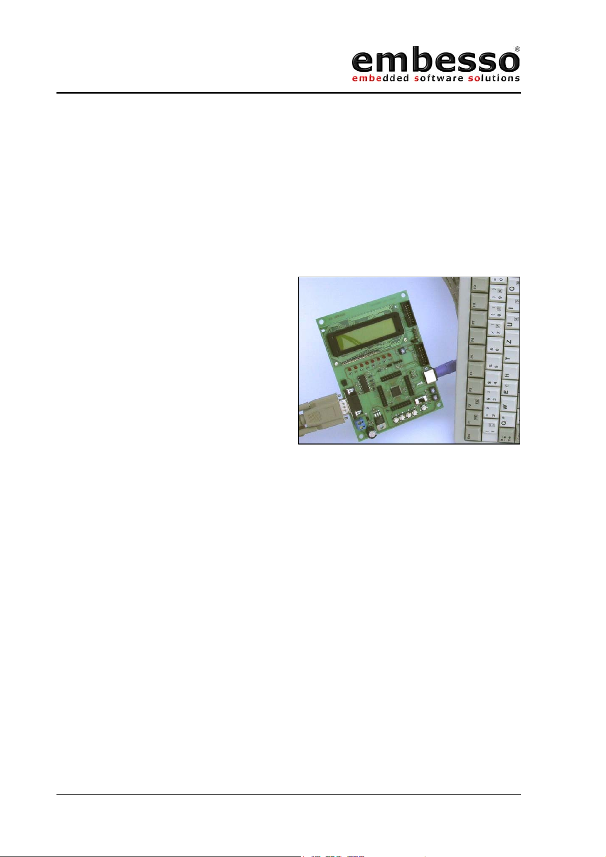
The Hitachi-Tiny-Eval-Board (HTEB1) is a low cost multifunctional
evaluation board for the Hitachi Tiny H8/3664F microcontroller. It can be
used stand alone for software development and testing or as a simple
target board. You can use the Flash-Download-Tool (FDT) for
programming the target code or work with a debug system (E10T) at the
provided connector. The board allows the designer immediately to start
with the software development before his own final target system is
available.
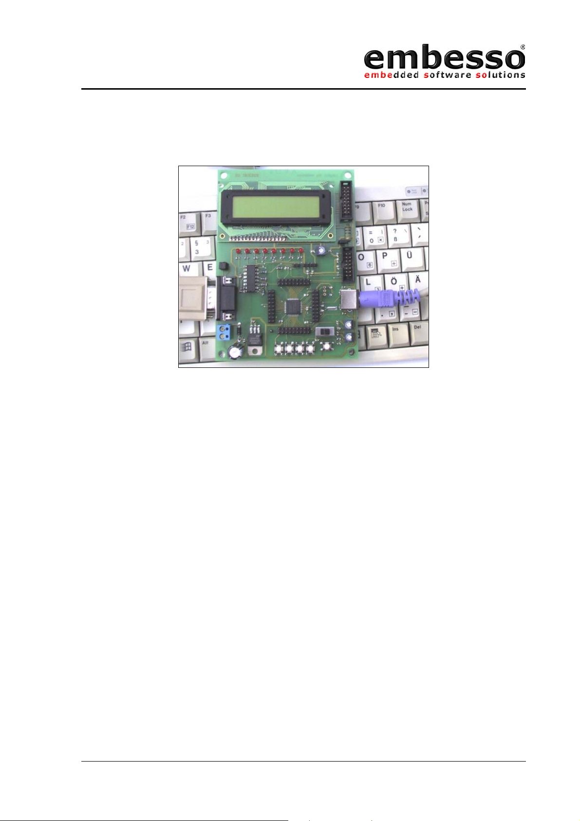
This eval-kit provides some additional hardware e.g. 8 LED’s, a 2*16
Character LCD, 4 key’s, a PC-AT-keyboard connector, an I2C-connector
and more for hard- and software evaluation. All peripherals are used by
some software application notes. Please refer chapter 3.
Issue 0.2 Page 4 07/2002
Page 5
HTEB1
User manual
1.3 Features
• Contains H8/3664F microcontroller
• In-Circuit serial Flash programming
• All resources available for evaluation
• All pins routed to connectors
• 9.8304 MHz main crystal
• 32.768 kHz sub crystal
• UART interface with MAX232 level converter and SubD-9 (female)
connector
• 8 User LEDs
• 2*16 characters LCD with LED backlight (switchable)
• Additional connector for external LCD
• 4 user keys
• PC-AT-Keyboard interface
• 2 potentiometer connected to A/D-channel 0/1
• Reset button
• 1 switch user/prog(programming)
• E10T-debug-connector
• +5V voltage regulator on board
Issue 0.2 Page 5 07/2002
Page 6
HTEB1
Prog/Run
User manual
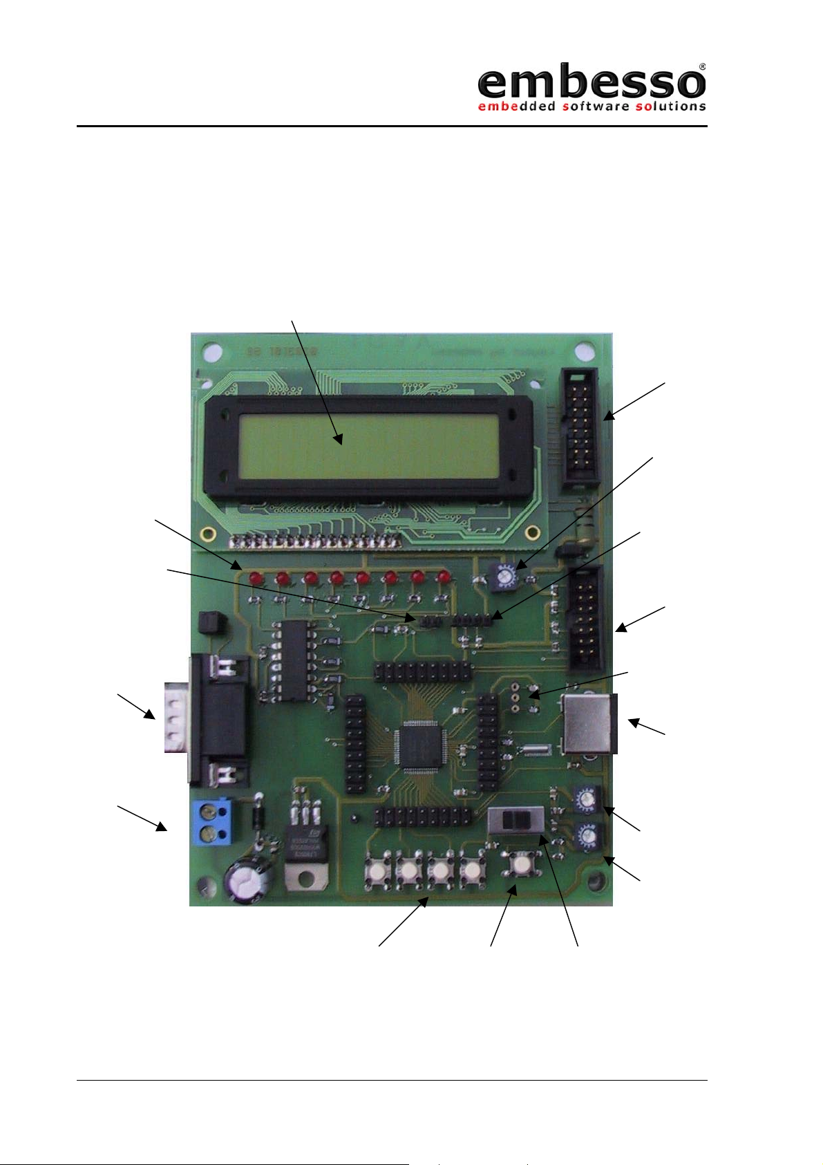
1.4 Board overview
2*16 char LCD with
LED backlight
Ext.-LCD
connector
Contrast
8 user LEDs
DA connector
RS232
connector
SubD0
female
Power 7,5 V9V DC
I2C
connector
E10T
connector
Crystal
socket
AT/PS2
keyboard
connector
+
-
P1 = ADC 0
P2 = ADC 1
4 user keys Reset button
Figure 1 Board overview
Issue 0.2 Page 6 07/2002
switch
Page 7
HTEB1
User manual
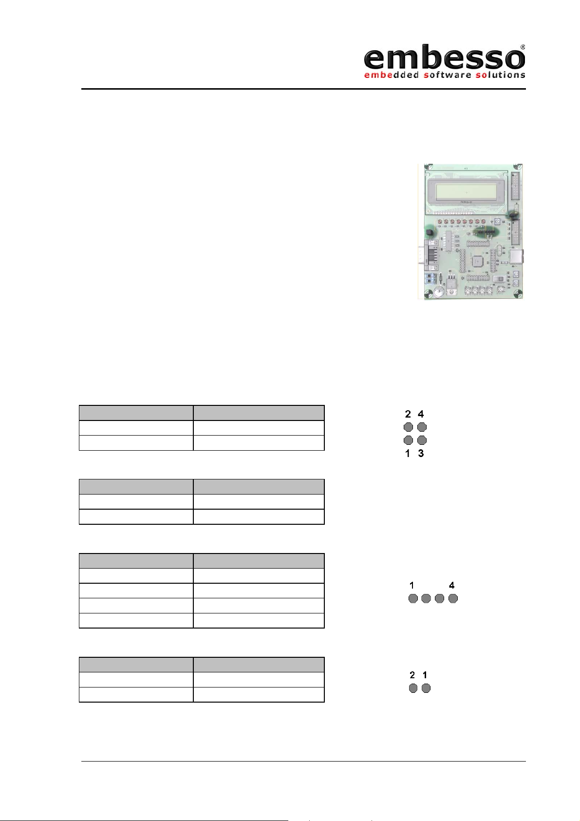
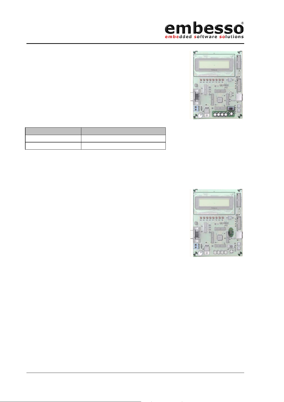
1.5 Jumpers and switches
JP1 is used for switching the serial interface from 1:1
to crossed connection. If you connect a 1:1 cable (like
the cable that comes with the kit) use the default
setting. If you connect a crossed cable set the jumper
to alternate setting.
JP3 is used for the LCD-LED backlight. If the jumper is
closed (1-2) the backlight will be ON. Remove the
jumper (=open) if backlight operation is not
necessary.
JP2 is used for I2C interface
JP4 is used as an output for the DAC or for PWM
JP1 Operation
1-3, 2-4 1:1 operation
1-2, 3-4 Crossed connection
JP3 Operation
Closed LED backlight ON
Open LED backlight OFF
JP2, I2C-CON Operation
1+5V
2SDA
3SCL
4GND
JP4, D/A CON Operation
1 D/A Output (PWM)
2GND
Issue 0.2 Page 7 07/2002
Page 8
HTEB1
User manual
S_PROG/RUN switches between RUN- and
PROG(PROGRAMMING) mode.
KEY_1 (T1) to KEY_4 (T4) are user keys.
RESET_KEY (T7) is for reset.
Orientation Operation
LEFT PROG(programming) mode
RIGHT RUN mode
Main crystal (Q1) can be changed to another
frequency. Therefore a crystal socket is provided.
Please refer to the microcontroller hardware
documentation for recommended devices. The crystal
type should be a HC49 / HC49U type. Eventually
change the capacitors C6/C7 if necessary. If you
change the crystal frequency take care on possible
changes by flash download tool (see FDT manual).
Figure 1.5 crystal socket
Issue 0.2 Page 8 07/2002
Page 9
HTEB1
User manual
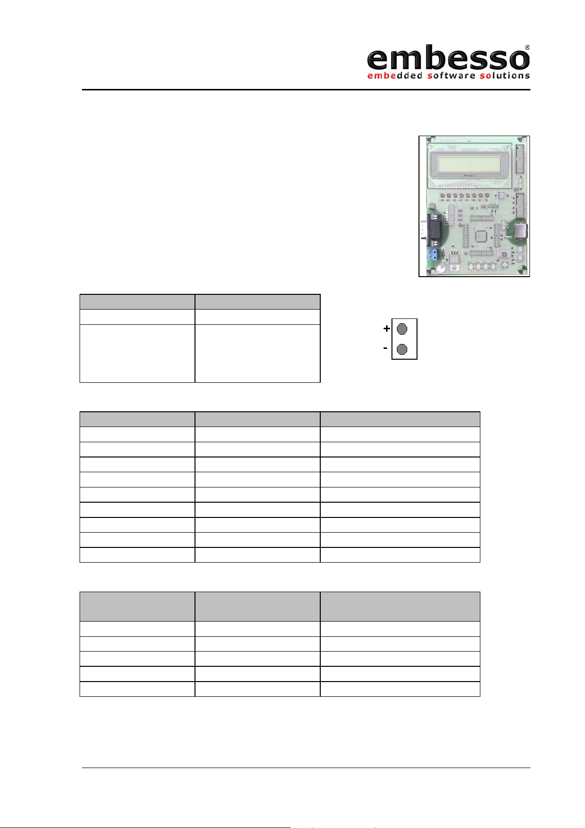
1.6 Connectors
X1, Serial communication, SubD-9 female
X2, Power connector, for cable connection
X4, MiniDIN (PS2)
X2, Pin Operation
1GND
2 DC power supply,
7,5 – 9 VDC,
approx. 180mA
with LED backlight
X1 (SubD9), Pin Operation Remark
1 (DTR,DSR, DTS) Connected to X1.4, X1.6
2 TXD Connected to JP1.1
3 RXD Connected to JP1.3
4 DTR Connected to X1.1, X1.6
5GND
6 DSR Connected to X1.1, X1.4
7 RTS Connected to X1.8
8 CTS Connected to X1.7
9 n.c. Not connected
X4 (Mini-Din)
µC-Pin Operation
Pin
1 P17 (can be Data or Clk)
5 P16 (can be Clk or Data)
3GND
4Vcc
2,6 n.c.
Issue 0.2 Page 9 07/2002
Page 10
HTEB1
User manual
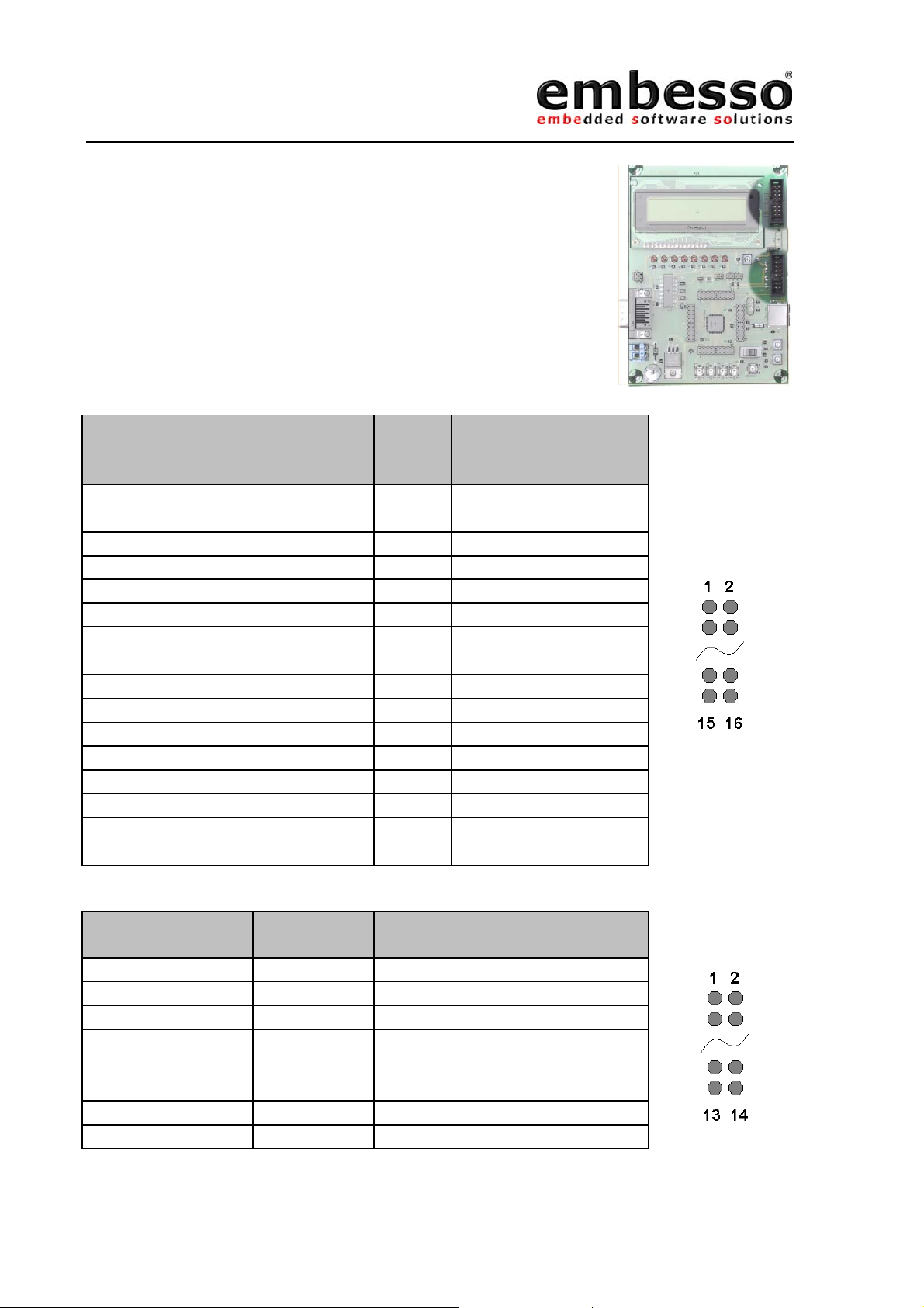
OnBoard LCD (IC4)
X3, external LCD-connector (057-016-1)
X5, E10T debug connector (Sys-Con)
LCD Modul
(IC4) pin
X3 (LCD-CON)
(057-016-1)
µCpin
Operation
pin
31 -GND
42 -Vcc
5 3 - contrast (=P3)
6 4 P75 RS (register select)
7 5 P74 R/W (read / write)
8 6 P20 EN (enable)
97 P50D0
10 8 P51 D1
11 9 P52 D2
12 10 P53 D3
13 11 P54 D4
14 12 P55 D5
15 13 P56 D6
16 14 P57 D7
1 15 - Backlight +
216 -GND
X3 pinout
X5 (SYS-CON),
pin
µC-pin Operation
X5 pinout
1 P87 Debug pin
5 P86 Debug pin
7 /NMI /NMI
11 P85 Debug pin
13 /RESET reset control
8Vcc
2,4,6,10,12,14 GND
3,9 n.c. Not connected
Issue 0.2 Page 10 07/2002
Page 11
HTEB1
User manual
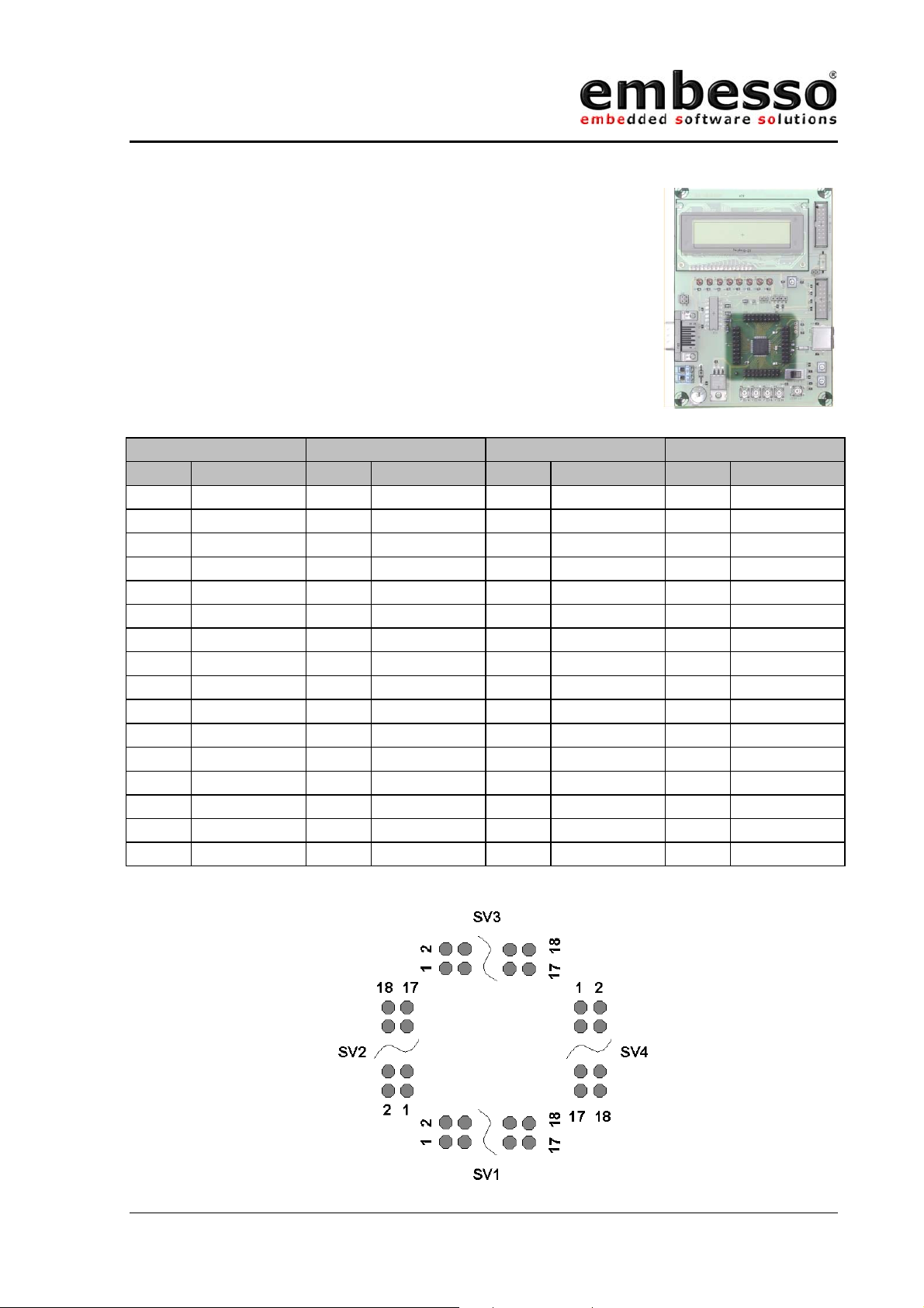
SV1,SV2, SV3,SV4 connectors with microcontroller
signals
SV1 SV2 SV3 SV4
PIN Operation PIN Operation PIN Operation PIN Operation
1,2 GND 1,2 GND 1,2 GND 1,2 GND
3 n.c. 3 n.c. 3 n.c. 3 P51
4 n.c. 4 n.c. 4 n.c. 4 P50
5 P14 5 P22 5 P76 5 n.c.
6 P15 6 P21 6 P75 6 n.c.
7 P16 7 P20 7 P74 7 n.c.
8 P17 8 P87 8 P57 8 n.c.
9AN4 9P86 9P56 9n.c.
10 AN5 10 P85 10 P12 10 n.c.
11 AN6 11 P84 11 P11 11 n.c.
12 AN7 12 P83 12 P10 12 n.c.
13 AN3 13 P82 13 P55 13 GND
14 AN2 14 P81 14 P54 14 /RESET
15 AN1 15 P80 15 P53 15 VCL
16 AN0 16 /NMI 16 P52 16 n.c.
17,18 Vcc 17,18 Vcc 17,18 Vcc 17,18 Vcc
Issue 0.2 Page 11 07/2002
Page 12
HTEB1
User manual
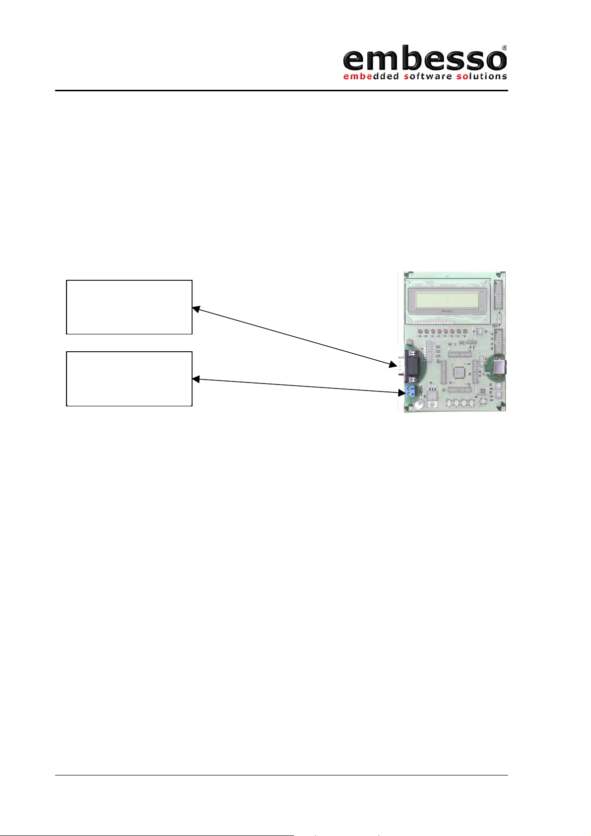
1.7 Start-Up instructions
1.7.1 Installing the HTEB1
Installing the HTEB1 requires a power supply and a serial connection to a
host computer (common PC). The serial communications cable for
connecting the HTEB1 to a host computer is supplied and has 1:1
connectivity.
PC with COM1/2
Power supply
7,5-9V DC
Figure 1.8 shows how to connect the HTEB1 to a PC and to a power supply
1.7.2 Power Supply
The HTEB1 hardware requires a power supply of 7,5V DC at minimum.
Please don’t use a power supply with more the 9V DC because the on
board voltage regulator becomes very hot!
The HTEB1 power consumption is about 180mA with LCD-backlight ON.
Since total power consumption can vary widely due to external
connectors, H8/3664F port state, use a power supply capable of providing
at least 300mA at +7,5V DC.
The design includes circuitry for reversed polarity protection.
Please watch on GND (ground) connection between power supply, evalboard and PC.
Issue 0.2 Page 12 07/2002
Page 13
HTEB1
User manual
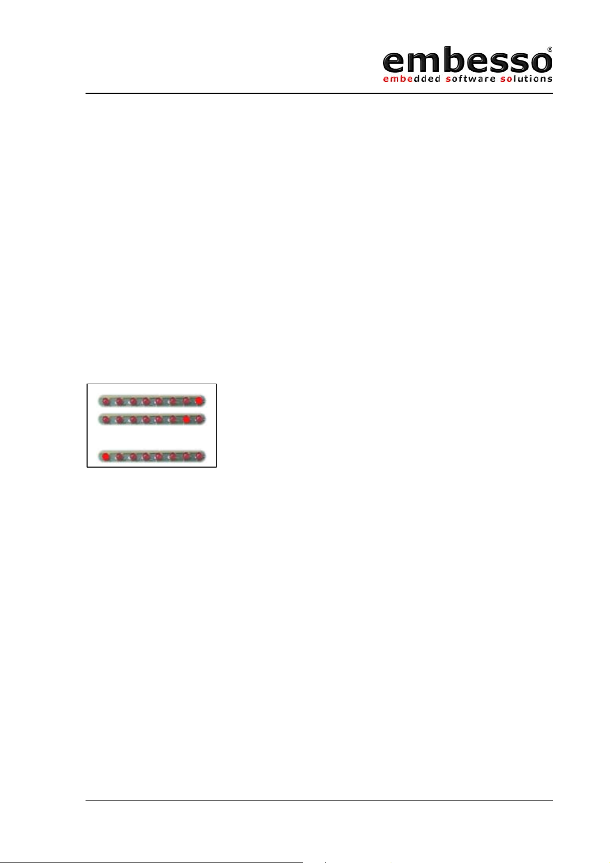
1.7.3 Test program
The HTEB1 is supplied with a short demo application when delivered. If
you power up the eval-board for the first time, you will see a start up
message and some LEDs lighting.
If no message appear, please set the switch “Prog/Run” to “Run-Mode”
(right position) and power up the board or, if already done, press the
reset-button.
The demo application contains a small “Running-Light” application. The
keys can be used for control the state, P2 is used as speed control. First
press the key T3 (RUN) for starting demo application. Then you can check
the functionality by pressing the keys KEY T1 to KEY T4 or change the
value of potentiometer P2.
[…]
Figure of the Demo application. “Running Light”
Any time you want to reset the application press the reset-button. If you
want to reload the demo application later (after reprogrammed the evalboard) you can find the code on CD-R in the directory
“X:\examples\flashdemo\runlight.a37” (For X use the appropriate char
from your CD-ROM).
Issue 0.2 Page 13 07/2002
Page 14

HTEB1
User manual
1.7.4 Software Installation
Software development on embesso-HTEB1 requires some software tools to
be installed on your PC. All tools can be found on CD-R. Some of them
must be installed separately. Please refer on installation / setup
requirements.
You will find the following tools:
EWH8: IAR Embedded Workbench with a limited version of the IAR
C compiler for all Hitachi Tiny controllers, assembler, linker
and library generator
FDT: A powerful freeware flash tool (flash-writer) from HMSE
Installation hints:
EWH8: Install EWH8 by start \programs\iar\autorun.exe . Follow
the instructions in setup and look at the readme.txt file.
FDT: Next install \programs\fdt\ftd15.exe. Then the plugin
fdt3664f.exe must be installed. Follow the setup
instructions. A documentation will be found in fdt_man.pdf.
If you have installed these tools please refer to the next lessons for
workflow.
NOTE: Most freeware tools are unsupported versions! Please refer
to manuals or hints on website for FAQ’s!
It is strongly recommended to refer all additional documents like
H8/3664F hardware manual and H8 programming manual. Please see the
application notes and several readme files on CD-R. Sometimes you
should watch on the Hitachi, HMSE and IAR websites for tool upgrading,
news and latest versions of all tools.
Hitachi: www.hitachi-eu.com/semiconductors
HMSE: www.hmse.com
IAR: www.iar.com
Issue 0.2 Page 14 07/2002
Page 15
HTEB1
User manual
2 Development Environment
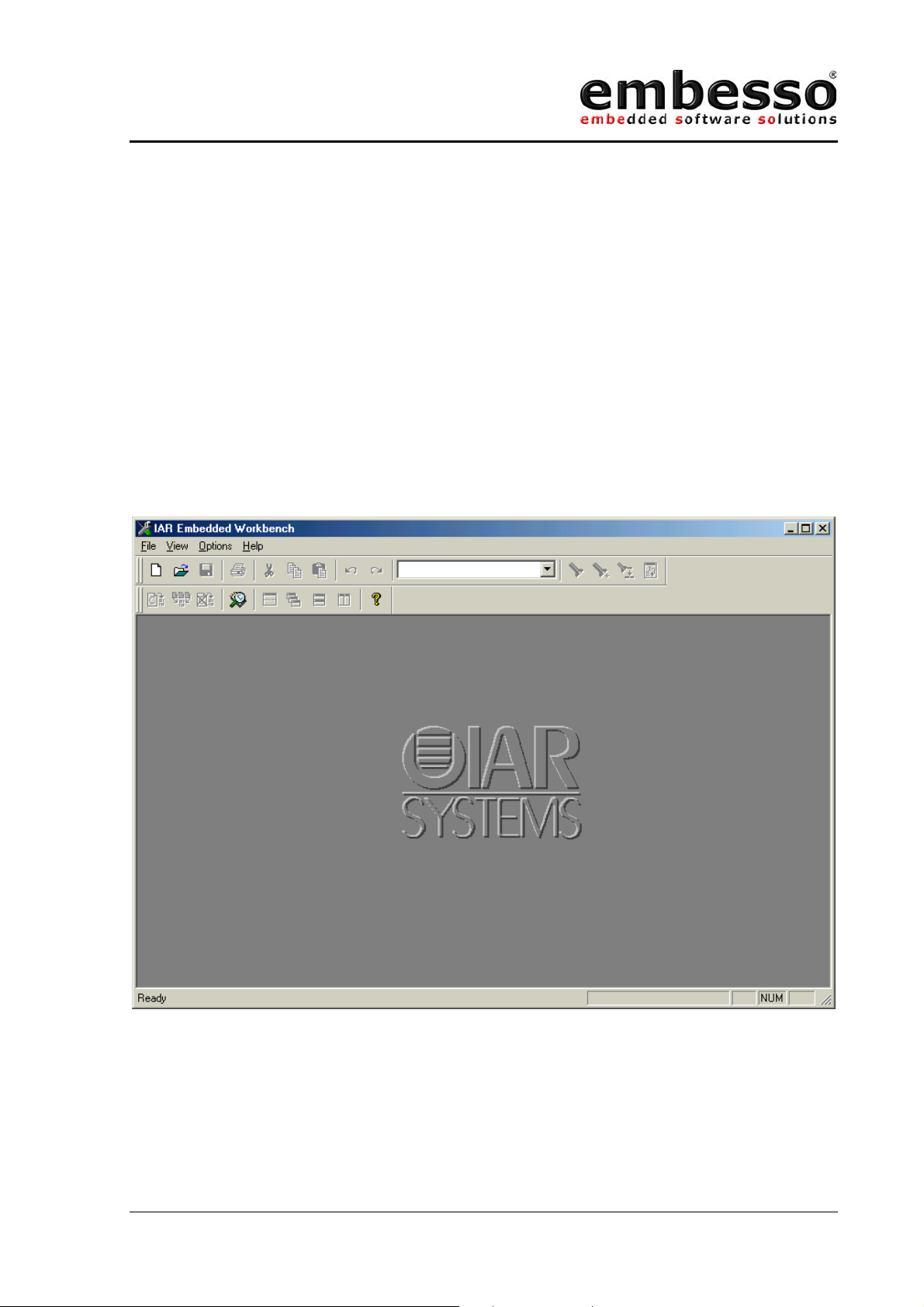
2.1 Creating a program using IAR-EWH8
Software development can be done with a integrated embedded
workbench like IAR-EWH8. This software contains an editor, some tools
for organization and a tool chain for compiling, assembling and linking
programs.
Start IAR Embedded Workbench on your PC. The following window will
appear:
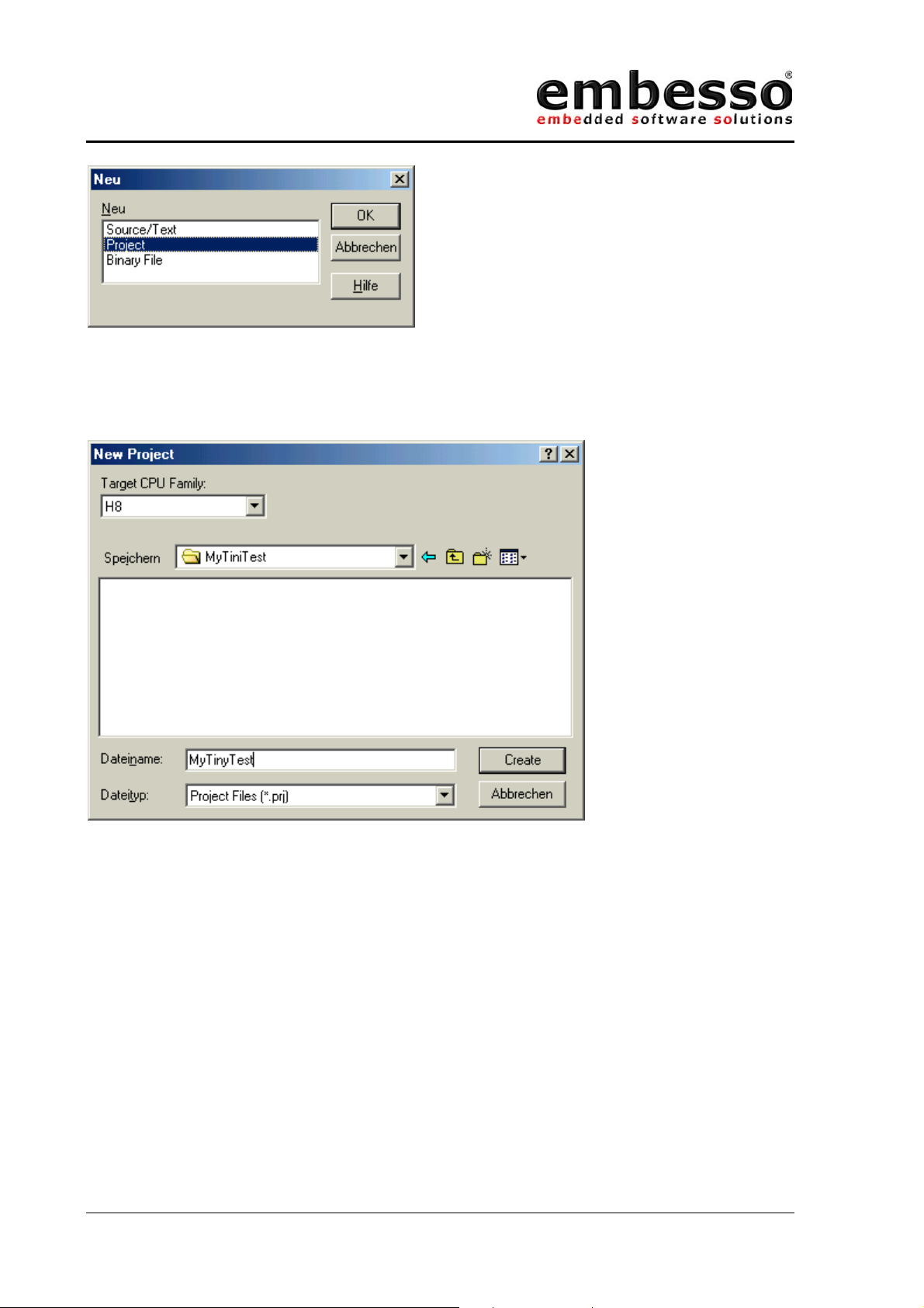
Now select File / New and select “Project”
Issue 0.2 Page 15 07/2002
Page 16
HTEB1
User manual
Press OK and a file window will appear. Here first create a new directory
(e.g. c:\MyTinyTest) and type the project filename “MyTinyTest”. After
that click CREATE.
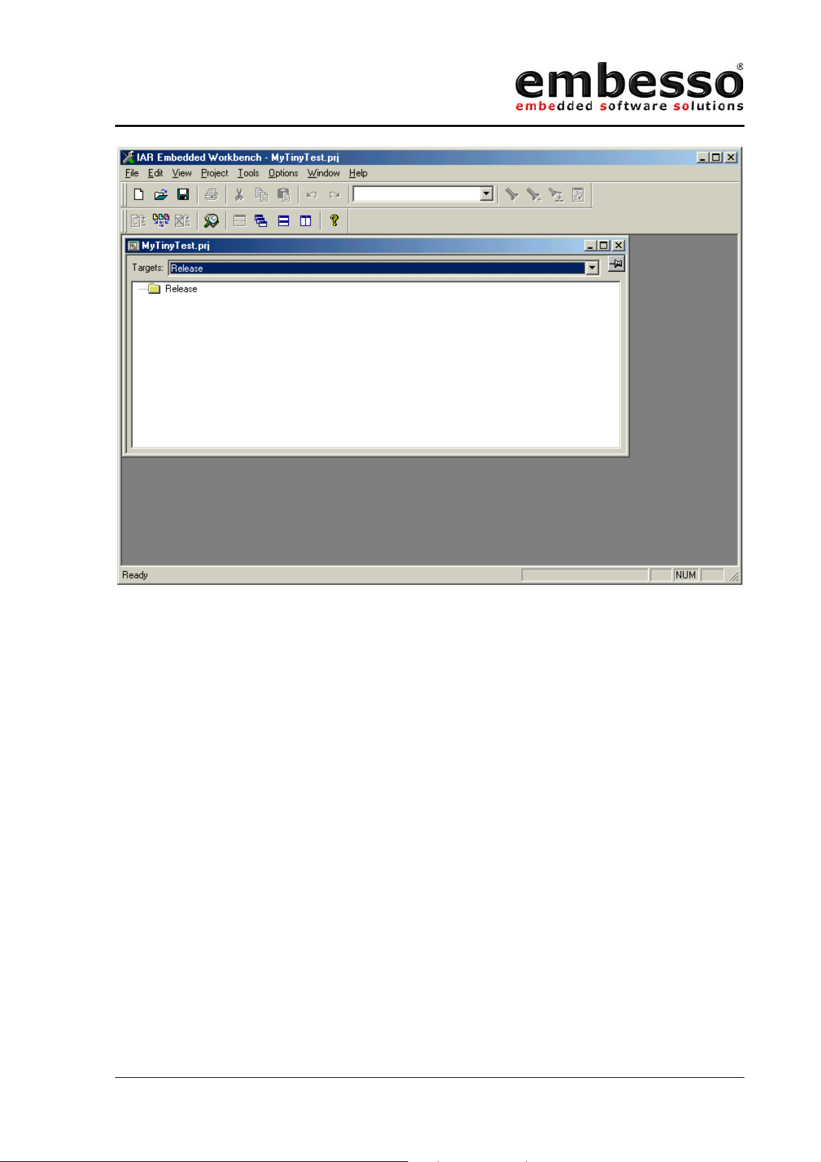
Now a new project is created and we must do some settings. In the
window select under targets: “RELEASE”.
Issue 0.2 Page 16 07/2002
Page 17
HTEB1
User manual
Now select release with the right mouse button. A popup appears. Select
Options… and do the following settings:
In selection ICCH8/List select the List file box.
In section XLINK/Output select under Format “motorola” as the output
format.
Issue 0.2 Page 17 07/2002
Page 18

HTEB1
User manual
On the CD-R you will find a file called “hteb1.xcl”. That file must be used
as the xlink input file. Please copy it to your target directory and select in
section Input/XCL file name the file hteb1.xcl.
Issue 0.2 Page 18 07/2002
Page 19

HTEB1
User manual
All other options can be changed later.
Click on OK.
Now select File/new/source file and type in the following program:
/* MyTinyTest */
#include "ioh83664.h"
void main(void)
{
unsigned int x=0; /* counter */
unsigned char c=0; /* holds port output */
PCR8 = 0xff; /* port is output */
PDR8 = c; /* all LED's on (inverse) */
while (1)
{
while (--x); /* wait ... */
c++; /* increment c */
PDR8 = c; /* to port */
}
}
Issue 0.2 Page 19 07/2002
Page 20

HTEB1
User manual
After that save it under MyTinyTest.c
Now we must add this file to our project. Please select Project/Files and
add the file MyTinyTest.c.
Issue 0.2 Page 20 07/2002
Page 21

HTEB1
User manual
After that click on DONE.
Now you can select Projet/Build ALL (or F9) and all files are compiled and
linked. The message window shows if your project is error free or if there
are any errors.
Issue 0.2 Page 21 07/2002
Page 22

HTEB1
User manual
The target file for download can be found in directory
c:\mytinytest\release\exe\mytinytest.a37.
Please see chapter “FDT” for information about downloading this file to
target system.
Issue 0.2 Page 22 07/2002
Page 23

HTEB1
User manual
2.2 Download the code using FDT
After compiling and linking (error free!), the target code (mytinytest.mot)
should be downloaded to target board. Therefore we use a freeware tool
from HMSE : FDT.
Even FDT must be prepared for a new workspace.
Issue 0.2 Page 23 07/2002
Page 24

HTEB1
User manual
Please start FDT and select „New Workspace“. Here we use the project
name “MyTinyTest”.
You can choose a location for all workspace files. Select on subdirectory
from „MyTinyTest“.
Click ok and a further window will appear:
Select „Yes“
Issue 0.2 Page 24 07/2002
Page 25

HTEB1
User manual
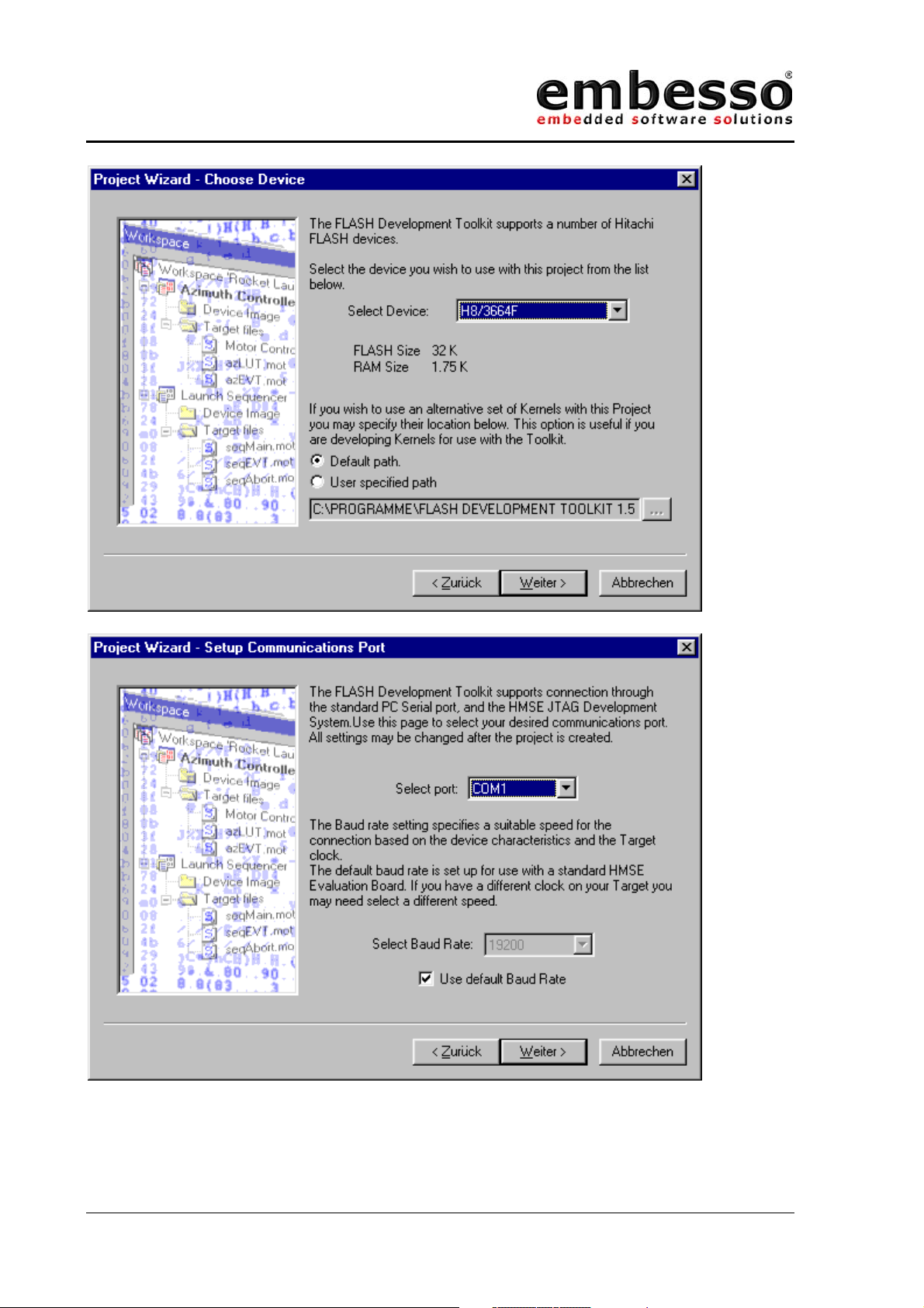
First time users should use the wizard!
Fill in the following things:
Issue 0.2 Page 25 07/2002
Page 26
HTEB1
User manual
Issue 0.2 Page 26 07/2002
Page 27

HTEB1
User manual
Issue 0.2 Page 27 07/2002
Page 28
HTEB1
User manual
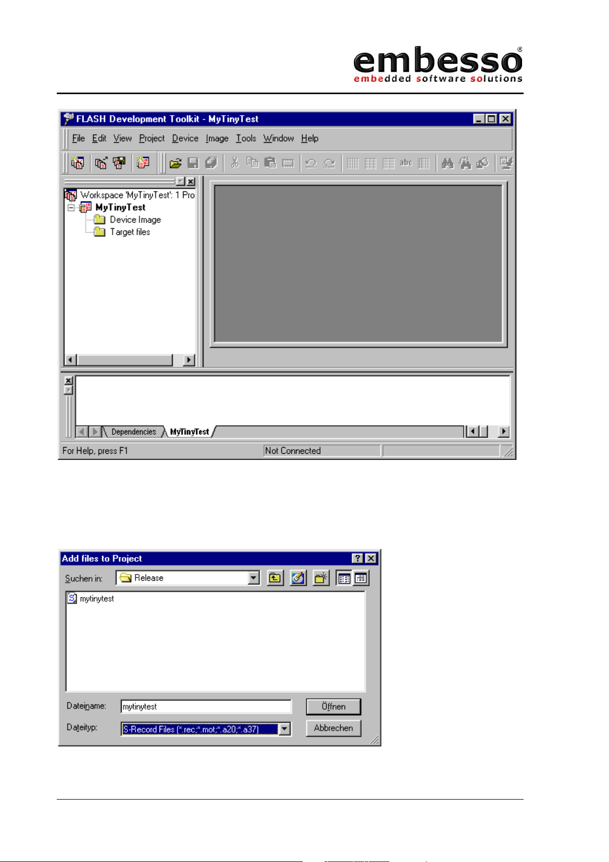
Now a workspace is created and you can add your target file to
„TargetFiles“:
Select Project/Add new files to project… and search for file:
c:\hew2\mytinytest\mytinytest\release\mytinytest.mot.
Issue 0.2 Page 28 07/2002
Page 29
HTEB1
User manual
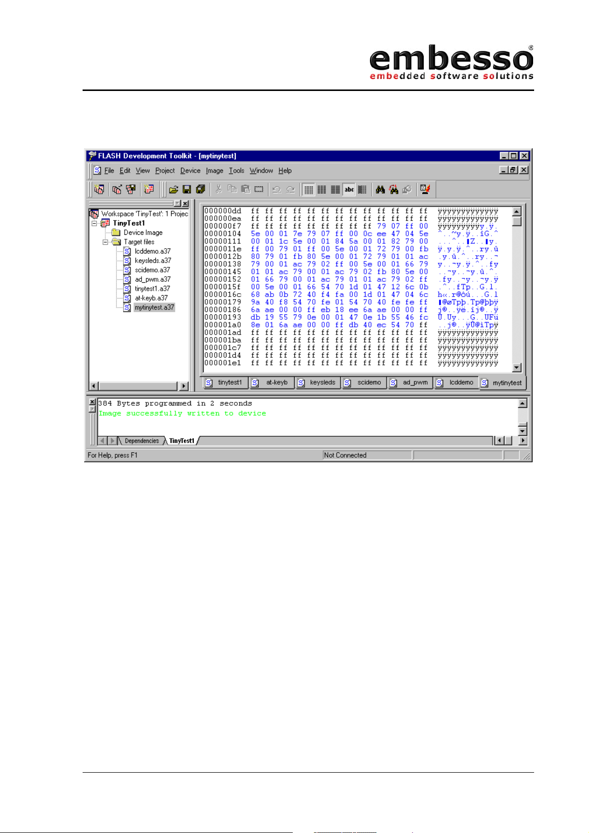
Now make a double click on \targetfiles\mytinytest and the file content of
mytinytest.mot will appear in hex format in the right window.
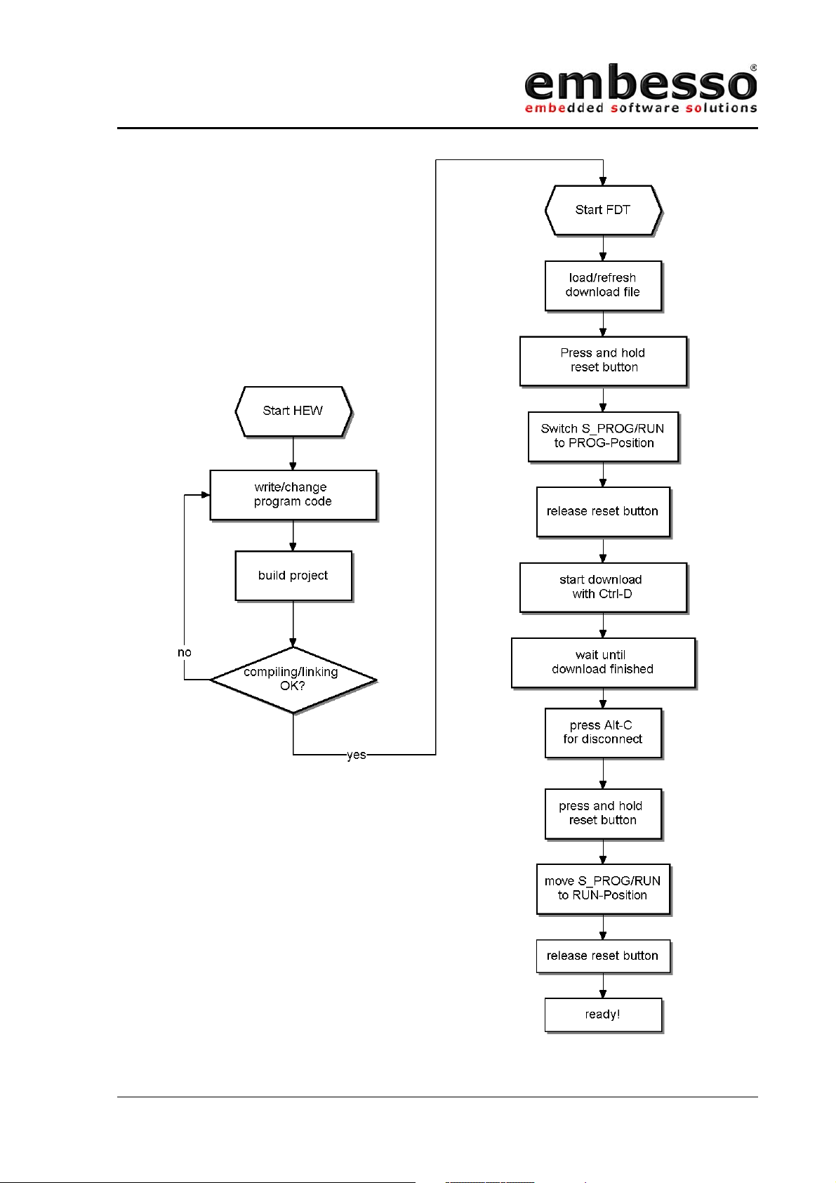
First press the reset button at the target board, hold it down and move
Prog/Run-switch to prog position (left). After that release the reset button.
With Image/Download image (Ctrl-P) you one can start the connection
setup to target board and start downloading image file.
Now press Ctrl-P (Download) on FDT and the download process will start.
Watch on progress bar while download.
When the download is finished press Alt-C to disconnect the PC
connection.
On target board, move Prog/Run-switch to run position (right) press down
the reset button and release reset button.
Congratulations! Now your first program is running!
You will see the LED’s flickering.
Issue 0.2 Page 29 07/2002
Page 30

HTEB1
User manual
Now you can do some additional functions in HEW. After compiling and
linking only go to FDT, update your download file with the command
Freshen all Target files (Ctrl-T), reconnect the link and repeat the
download process.
Issue 0.2 Page 30 07/2002
Page 31
HTEB1
User manual
2.3 Workflow
Issue 0.2 Page 31 07/2002
Page 32

HTEB1
User manual
3 Examples
HTEB1 is provided with some demonstration code.
On the supplied CD-R you should find a complete prepared workspace for
IAR-EWH8.
\examples\demoapp\demoapp.prj
Please copy the complete directory to your hard disk in a directory
c:\H8TinyIAR, so you will finally have the following directory (per
example) “c:\H8TinyIAR\examples\demoapp\” with all application notes
included.
Then start IAR-Ewh8 and select “open existing workspace”. Select one of
the projects and do your exercises.
For all projects we need the same header file containing some definitions
and the include file for the target microcontroller H8/3664F. So if you
want to work with these files don’t forget to include the file “mydefs.h”
first in your project file:
#ifndef _MYDEFS_H_
#define _MYDEFS_H_
#include "ioh83664.h" // select processortype here
#include "inh8.h"
#include "icclbutl.h"
#define CPU_CLK 9830400 // select clk for diff. calc.
#ifndef NULL
#define NULL 0x00
#endif
#ifndef FALSE
#define FALSE 0x00
#endif
#ifndef TRUE
#define TRUE 0x01
#endif
typedef unsigned char u8;
typedef unsigned int u16;
#endif
Issue 0.2 Page 32 07/2002
Page 33

HTEB1
User manual
3.1 Key’s and LED’s
The first demo program shows the usage of LEDs and keys on HTEB1. For
time-controlling we use TIMER_A as an periodic interval timer. The
interrupt service routine (isr) is checking the state of the keys, actualising
the LED port and reading out the AD1-channel to determine the running
light speed. If you want to do some experiments, first check out to find if
other LED pattern maybe in form of a table read out or calculate them by
functions developed by yourself. If speed control should be changed, first
change the calculation of the A/D-conversion value to timer ticks.
/*-----------------------------------------------------------------** KeysLEDs.c contains some sample code for using LEDs and Key's
** on TinyEvalBoard
** in addition Timer_A is used for timer tick with irq
**-----------------------------------------------------------------*/
#include "mydefs.h" // for all nec. includes
/* defines */
#define KEY_1 0x10
#define KEY_2 0x20
#define KEY_3 0x04
#define KEY_4 0x02
#define KEY_ALL (KEY_1|KEY_2|KEY_3|KEY_4)
#define KEY_RELEASED 0x40
#define KEY_PROCESSED 0x80
#define LED_SPEED_INIT4 // = 4/32 = 1/8s = 125ms
/* variables */
u8 KeyCode=0;
u8 LED_Out, LED_Dir, LED_Run, LED_Speed;
/* functions */
void KeyCheck(void)
{
if ((PDR1 & KEY_ALL) != KEY_ALL) // is any key pressed ?
{
if (!(PDR1 & KEY_1)) KeyCode = KEY_1;
else if (!(PDR1 & KEY_4)) KeyCode = KEY_4;
else if (!(PDR1 & KEY_3)) KeyCode = KEY_3;
else if (!(PDR1 & KEY_2)) KeyCode = KEY_2;
}
else
{
KeyCode = KEY_RELEASED; // no, mark key_released
}
}
void RunningLightUpdate(void) // check for keypresse
{ // and update LEDs
u8 dummy;
u16 adval;
if (!(KeyCode & KEY_RELEASED))
{
if ((KeyCode & KEY_1)==KEY_1) LED_Dir = 1;
else if ((KeyCode & KEY_4)==KEY_4) LED_Dir = 0;
else if ((KeyCode & KEY_2)==KEY_2) LED_Run = 0;
else if ((KeyCode & KEY_3)==KEY_3) LED_Run = 1;
KeyCode |= KEY_RELEASED;
Issue 0.2 Page 33 07/2002
Page 34

HTEB1
User manual
}
if (LED_Speed) LED_Speed--; // decrement speed counter
if (!LED_Speed) // if zero ...
{
LED_Speed = LED_SPEED_INIT; // re init speed counter
if (LED_Run)
{
}
}
PDR8 = ~LED_Out; // output (invert)
}
void PrepKeyPort(void) // prepare key-port-bits
{
PMR1 &= ~KEY_ALL; // Port1 = I/O (0) for all keys
PCR1 &= ~KEY_ALL; // Port1 = input(0) for all keys
PUCR1 |= KEY_ALL; // PullUps = on for all keys
}
if (LED_Dir) // right
{
LED_Out >>= 1; // shift right
if (!LED_Out) LED_Out = 0x80; // if empty, set to 0x80
}
else
{
LED_Out <<= 1; // shift left
if (!LED_Out) LED_Out = 0x01; // if empty, set to 0x01
}
void RunningLightInit(void) // prepare LED-port and vars
{
PrepKeyPort();
PDR8 = 0xff; // all LED's off
PCR8 = 0xff; // all out's
LED_Out = 0x01; // start value
LED_Run = 0x01; // run
LED_Dir = 0x00; // dir = left
LED_Speed = LED_SPEED_INIT; // start speed
}
/****************************************
TimerA-Interrupt (1s)
increments var c and output
the value of c to LED's (inverted)
****************************************/
interrupt [TIMER_A] void Timer_A_Isr(void)
{
static u8 c;
KeyCheck(); // check for key pressed
RunningLightUpdate();
IRR1 &= ~0x40; // clear irq-flag
}
/****************************************
TimerA-Test
setup : CLK/8 (=1µs @ 8MHz) at P10 (TMOW)
****************************************/
void Timer_A_Init(void)
{
PCR8 = 0xff; // P8 = output
TMA = 0x0c; // Reset PrescalerW
TMA = 0x4b; // CLK/8 on P10, 1/32s-interval (Clk=Prescaler W)
PMR1 |= 0x01; // set TMOW (P10) = Output
IENR1 |= 0x40; // enable TimerA-Interrupt
set_interrupt_mask(0); // enable all interrupts
}
1s-Irq-intervall @ SubClock (32.678 Hz)
void main(void)
{
Issue 0.2 Page 34 07/2002
Page 35

HTEB1
User manual
RunningLightInit(); // Init key's and LEDs
Timer_A_Init(); // init & start timer_A
while(1); // just wait ...
}
Issue 0.2 Page 35 07/2002
Page 36

HTEB1
User manual
3.2 LCD
One of the highlights of the HTEB1 is the 2*16 character LCD with
backlight. Simple functions are provided here to demonstrate the usage of
the LCD. Please refer to the LCD manual for further information (e.g.
commands, other character sets etc.).
The demo source contains some definitions to reset and initialise the
display. Then we make some simple write outs.
/*-----------------------------------------------------------------** LCDDemo shows some funcions of the LCD on the TinyEvalBoard
** Please refer to LCD datasheet for further details
**-----------------------------------------------------------------*/
#include "mydefs.h" // find further includes there!
void wait(u16 wastetime) // local LCD port delay
{
while(wastetime--);
}
/*
LCD-Port / Bits on TinyEvalBoard
RS = P75, R/W = P74, EN = P20, DATA = P5
*/
// some defines for easy access
#define CLEAR_LCD_RS (PDR7 &= ~0x20)
#define SET_LCD_RS (PDR7 |= 0x20)
#define CLEAR_LCD_RW (PDR7 &= ~0x10)
#define SET_LCD_RW (PDR7 |= 0x10)
#define CLEAR_LCD_EN (PDR2 &= ~0x01)
#define SET_LCD_EN (PDR2 |= 0x01)
#define LCD_DATA_PORT (PDR5)
#define LCD_DATA_CTRL (PCR5)
#define LCD_OUT 0xff
#define LCD_IN 0x00
#define LCD_WAIT {wait(100);}
void LCDWriteCmd(u8 cmd) // write cmd to LCD port
{
CLEAR_LCD_RS;
CLEAR_LCD_RW;
SET_LCD_EN;
LCD_DATA_PORT = cmd;
LCD_WAIT;
CLEAR_LCD_EN;
LCD_WAIT;
}
void LCDWriteData(u8 data) // write data to LCD port
{
SET_LCD_RS;
CLEAR_LCD_RW;
SET_LCD_EN;
LCD_DATA_PORT = data;
LCD_WAIT;
CLEAR_LCD_EN;
LCD_WAIT;
}
Issue 0.2 Page 36 07/2002
Page 37

HTEB1
User manual
u8 LCDReadStatus(void) // get the LCD status register
{
u8 status;
CLEAR_LCD_RS;
SET_LCD_RW;
LCD_DATA_CTRL = LCD_IN;
SET_LCD_EN;
status = LCD_DATA_PORT;
CLEAR_LCD_EN;
LCD_DATA_CTRL = LCD_OUT;
return status;
}
void LCDInit(void) // init LCD
{
u16 cnt=0;
CLEAR_LCD_RS;
CLEAR_LCD_RW;
CLEAR_LCD_EN;
PCR7 |= 0x30; // Set RS+RW = Output
PCR2 |= 0x01; // Set EN = Output
LCD_DATA_CTRL = LCD_OUT; // Set DDR to Output
LCDWriteCmd(0x38); // 8Bit-IF, 2 Lines, 5x7 character font
while(--cnt);
LCDWriteCmd(0x38); // 8Bit-IF, 2 Lines, 5x7 character font
while(--cnt);
LCDWriteCmd(0x38); // 8Bit-IF, 2 Lines, 5x7 character font
while(--cnt);
LCDWriteCmd(0x38); // 8Bit-IF, 2 Lines, 5x7 character font
while(--cnt);
// LCDWriteCmd(0x01); // Display Clear
// LCDReadStatus();
// LCDWriteCmd(0x0f); // DisplayOn, CursorOn, BlinkingOn
LCDWriteCmd(0x0c); // DisplayOn, CursorOff, BlinkingOff
LCDReadStatus();
LCDWriteCmd(0x06); // Enter Mode, AutoIncrement
LCDReadStatus();
LCDWriteCmd(0x14); // MoveCursor right
LCDReadStatus();
LCDWriteCmd(0x80); // Set DD RAM Address = 0x00
LCDReadStatus();
}
// writesomedata from 1st position in #line (0/1)
void LCDWriteLine(u8 line, const u8 *data)
{
LCDWriteCmd(0x80 + line*0x40); // select line
while (*data)
{
LCDWriteData(*data);
data++;
}
}
void Delay(void) // "manual" delay
{
long z = 0x200000;
while(--z);
}
const u8 Text1[17] = " embesso ";
const u8 Text2[17] = " presents ";
const u8 Text3[17] = " HITACHI ";
const u8 Text4[17] = " Tiny-H8/3664F ";
const u8 Text5[17] = "LowCostEvalBoard";
Issue 0.2 Page 37 07/2002
Page 38

HTEB1
User manual
void LCDLoopMsg(void)
{
while(1) // do forever...
{
LCDWriteLine(0,&Text1[0]); // display msgs
LCDWriteLine(1,&Text2[0]);
Delay();
LCDWriteLine(0,&Text3[0]);
LCDWriteLine(1,&Text4[0]);
Delay();
LCDWriteLine(0,&Text4[0]);
LCDWriteLine(1,&Text5[0]);
Delay();
}
}
void main(void)
{
LCDInit(); // init ports and LCD
LCDLoopMsg(); // go to LoopMsg
}
Issue 0.2 Page 38 07/2002
Page 39

HTEB1
User manual
3.3 SCI
SCI is used here for a simple RS232 (V24) terminal connection. Please use
a terminal program like HyperTerm (included in Windows), select
Baudrate 9600 Baud, 8 Databits, No Parity and 1 Stopbit (8N1). After
connection and setup, hit some keys and you will see a message
responding on every keycode sent.
/*
**----------------------------------------------------------------------**
** main.c - contains C entry point main()
**
** This file was generated by HEW IAR Icch8 project generator
**
**----------------------------------------------------------------------*/
#include "mydefs.h" // see file for further include
/* some defines */
#define TIE 0x80
#define RIE 0x40
#define TE 0x20
#define RE 0x10
#define MPIE 0x08
#define TEIE 0x04
#define CK_INT 0x00
#define CK_INT_OUT 0x01
#define CK_EXT 0x02
#define IS_SCI_RDF (SSR & 0x40)
#define CLEAR_SCI_RDF SSR = (SSR & ~0x40)
#define IS_SCI_TX_FREE (SSR & 0x80)
#define V24_BRR(x) ((unsigned char)(((CPU_CLK+16*x)/32/x) - 1))
void V24Init (u16 Baudrate)
{
SCR3 = 0x00; // disable all
SSR = 0x00; // clear all errorbits
SMR = 0x00; // 8N1 + /1 clock
BRR = V24_BRR(Baudrate); // set baud
PMR1 |= 0x02; // P22 = TxD Output
SCR3 = (TE|RE|CK_INT); // Ints und Data disabled, internal clock
}
u8 V24NewChar(void) // check for new char on V24
{
if (IS_SCI_RDF) // Receive buffer full?
{
return TRUE;
}
return FALSE;
}
u8 V24GetChar(u8* data) // simple GetChar via V24
{
u8 idx;
if (IS_SCI_RDF) // Receive buffer full?
{
*data = RDR; // yes, get data
CLEAR_SCI_RDF; // clear RDRF-Bit
Issue 0.2 Page 39 07/2002
Page 40

HTEB1
User manual
return TRUE;
}
return FALSE;
}
u8 V24PutChar(u8 c) // simple PutChar via V24
{
if (IS_SCI_TX_FREE) // Tx register free ?
{
TDR = c; // yes, put data in tx register
return TRUE;
}
return FALSE;
}
u8 V24Write(u8 *s) // simple Write(string) via V24
{
while (*s != 0) // while not end of string
{
if (V24PutChar(*s) == TRUE) s++; // PutChar
}
return TRUE;
}
u8 V24WriteLn(u8 *s) // simple WriteLine (string + CR/LF)
{
u8 ret = FALSE;
ret = V24Write(s);
ret |= V24Write("\n\r");
return ret;
}
void ShowUse(void) // simple menu
{
V24WriteLn("\n\n\rV24-DemoProgram");
V24WriteLn("-1- Line 1");
V24WriteLn("-2- Line 2");
V24Write("make your choise :");
}
void main(void)
{
char c;
V24Init(9600); // init sci with 9600Baud, 8N1
ShowUse(); // display start msg
while(1) // loop ...
{
if (V24GetChar(&c)==TRUE)
{
}
}
if (c=='1')
{
V24WriteLn("\n\n\rGreat! This was '1'");
}
else if (c=='2')
{
V24WriteLn("\n\n\rSuper! '2'");
}
else
{
V24WriteLn("\n\n\rSorry! Only '1' or '2' are supported!");
}
ShowUse();
}
Issue 0.2 Page 40 07/2002
Page 41

HTEB1
User manual
3.4 A/D + PWM
This sample shows the usage of the A/D converter. We sample the voltage
of P1/P2, filter it and show the result on the LCD. On D/A-Con you will see
a reversed voltage at P2 – built with a RC-filter from TOW (P76).
/*-----------------------------------------------------------------** AD_PWM Demo shows some funcions of the A/D converter
** and the use of PWM (= inverse output from P2) at D/A-Con
**-----------------------------------------------------------------*/
#include "mydefs.h" // with further includes!
#include "stdlib.h" // for abs()
void wait(u16 wastetime) // local LCD port delay
{
while(wastetime--);
}
/*
LCD-Port / Bits on TinyEvalBoard
RS = P75, R/W = P74, EN = P20, DATA = P5
*/
// some defines for easy access
#define CLEAR_LCD_RS (PDR7 &= ~0x20)
#define SET_LCD_RS (PDR7 |= 0x20)
#define CLEAR_LCD_RW (PDR7 &= ~0x10)
#define SET_LCD_RW (PDR7 |= 0x10)
#define CLEAR_LCD_EN (PDR2 &= ~0x01)
#define SET_LCD_EN (PDR2 |= 0x01)
#define LCD_DATA_PORT (PDR5)
#define LCD_DATA_CTRL (PCR5)
#define LCD_OUT 0xff
#define LCD_IN 0x00
#define LCD_WAIT {wait(100);}
void LCDWriteCmd(u8 cmd) // write cmd to LCD port
{
CLEAR_LCD_RS;
CLEAR_LCD_RW;
SET_LCD_EN;
LCD_DATA_PORT = cmd;
LCD_WAIT;
CLEAR_LCD_EN;
LCD_WAIT;
}
void LCDWriteData(u8 data) // write data to LCD port
{
SET_LCD_RS;
CLEAR_LCD_RW;
SET_LCD_EN;
LCD_DATA_PORT = data;
LCD_WAIT;
CLEAR_LCD_EN;
LCD_WAIT;
}
u8 LCDReadStatus(void) // get the LCD status register
{
u8 status;
CLEAR_LCD_RS;
SET_LCD_RW;
Issue 0.2 Page 41 07/2002
Page 42

HTEB1
User manual
LCD_DATA_CTRL = LCD_IN;
SET_LCD_EN;
status = LCD_DATA_PORT;
CLEAR_LCD_EN;
LCD_DATA_CTRL = LCD_OUT;
return status;
}
void LCDInit(void) // inits the LCD
{
u16 cnt=0;
CLEAR_LCD_RS;
CLEAR_LCD_RW;
CLEAR_LCD_EN;
PCR7 |= 0x30; // Set RS+RW = Output
PCR2 |= 0x01; // Set EN = Output
LCD_DATA_CTRL = LCD_OUT; // Set DDR to Output
// required 3 times pls. ref. data sheet
LCDWriteCmd(0x38); // 8Bit-IF, 2 Lines, 5x7 character font
while(--cnt);
LCDWriteCmd(0x38); // 8Bit-IF, 2 Lines, 5x7 character font
while(--cnt);
LCDWriteCmd(0x38); // 8Bit-IF, 2 Lines, 5x7 character font
while(--cnt);
LCDWriteCmd(0x38); // 8Bit-IF, 2 Lines, 5x7 character font
while(--cnt);
LCDWriteCmd(0x0c); // DisplayOn, CursorOff, BlinkingOff
LCDReadStatus();
LCDWriteCmd(0x06); // Enter Mode, AutoIncrement
LCDReadStatus();
LCDWriteCmd(0x14); // MoveCursor right
LCDReadStatus();
LCDWriteCmd(0x80); // Set DD RAM Address = 0x00
LCDReadStatus();
}
// writesomedata from 1st position in #line (0/1)
void LCDWriteLine(u8 line, u8 *data)
{
LCDWriteCmd(0x80 + line*0x40); // select line
while (*data)
{
LCDWriteData(*data);
data++;
}
}
#define ADDR_A (*(volatile unsigned short *)(0xFFB0))
#define ADDR_B (*(volatile unsigned short *)(0xFFB2))
u16 Read_AD(u8 channel)
{
u8 dummy;
u16 adval;
dummy = ADCSR; // dummy read
ADCSR = 0x00; // reset A/D
ADCSR |= (0x20 + (channel &0x01)); // start A/D, channel 0 or 1
while (!(ADCSR & 0x80)); // wait conversion end
if (channel & 0x01) adval = ADDR_B; // read A/D-value
else adval = ADDR_A;
return adval>>6;
}
u8 Line0[] = " A/D#0=P1=0x \0";
u8 Line1[] = " A/D#1=P2=0x \0";
// convert int to ASCII-HEX
void ShowHexValue(u16 code, u8 line)
Issue 0.2 Page 42 07/2002
Page 43

HTEB1
User manual
{
u8 *data, *text, c,d;
if (line==0) text = &Line0[0]; // last digit = start address
else text = &Line1[0];
data = text+14;
d=3;
while (d)
{
*data = '0'; // default = '0'
c = code & 0x000f; // check digit
if (c) // if > 0 chk for value
{
}
data--; // next digit
code >>= 4;
d--;
}
LCDWriteLine(line,text); // show result
}
void Delay(void) // "manual" delay
{
long z = 0x010000;
while(--z);
}
if (c < 10) *data = '0'+c; // 0..9
else *data = 'A'+c-10; // a..f
u16 oldval[2];
u16 Average(u8 channel, u16 adval) // calculate av of last 15 values
{
if ((abs)(oldval[channel]-adval)>10)
oldval[channel]=adval;
else
oldval[channel] = ((oldval[channel]*15)+adval)>>4;
return oldval[channel];
}
/****************************************
TimerV-Test
setup : CLK/8 (=1µs @ 8MHz)
****************************************/
void Test_Timer_V(void)
{
TCRV0 = 0x08|0x01; // Clear by CompMatchA; IntClk/8
TCRV1 = 0x01; // Clk/2, no external Trigger
TCSRV = 0x08|0x01; // 0=onCompMatchA, 1=onCompMatchB (output on P76)
TCORA = 100; // set periode to 100 => 10.000Hz
TCORB = 75; // set init dutycycle to 75%
}
void main(void)
{
u16 val;
LCDInit(); // init ports and LCD
Test_Timer_V(); // for PWM-Output
while(1) // do forever...
{
val = Average(0,Read_AD(0));
ShowHexValue(val,0);
val = Average(1,Read_AD(1));
ShowHexValue(val,1);
PWM-Output at TMOV (P76)
val /= 10; // max. 1023/10 = 102
TCORB = (unsigned char)(val & 0xff); // set PWM-output
Delay();
}
}
Issue 0.2 Page 43 07/2002
Page 44

HTEB1
User manual
3.5 AT-Keyboard-Interface
This demo shows the usage of the PS2 (mini-DIN) interface on HTEB1.
Please connect an AT-keyboard (MF102) to this port. You will see the
keycodes, provided by the keyboard on the LCD. Please refer to the code
table for keycode translation in your own projects.
/*-----------------------------------------------------------------** AT-Keyb shows the PS2-Interface to an AT-Keyboard
**-----------------------------------------------------------------*/
#include "mydefs.h" // with further includes!
void wait(u16 wastetime) // local LCD port delay
{
while(wastetime--);
}
/*
LCD-Port / Bits on TinyEvalBoard
RS = P75, R/W = P74, EN = P20, DATA = P5
*/
// some defines for easy access
#define CLEAR_LCD_RS (PDR7 &= ~0x20)
#define SET_LCD_RS (PDR7 |= 0x20)
#define CLEAR_LCD_RW (PDR7 &= ~0x10)
#define SET_LCD_RW (PDR7 |= 0x10)
#define CLEAR_LCD_EN (PDR2 &= ~0x01)
#define SET_LCD_EN (PDR2 |= 0x01)
#define LCD_DATA_PORT (PDR5)
#define LCD_DATA_CTRL (PCR5)
#define LCD_OUT 0xff
#define LCD_IN 0x00
#define LCD_WAIT {wait(100);}
void LCDWriteCmd(u8 cmd) // write cmd to LCD port
{
CLEAR_LCD_RS;
CLEAR_LCD_RW;
SET_LCD_EN;
LCD_DATA_PORT = cmd;
LCD_WAIT;
CLEAR_LCD_EN;
LCD_WAIT;
}
void LCDWriteData(u8 data) // write data to LCD port
{
SET_LCD_RS;
CLEAR_LCD_RW;
SET_LCD_EN;
LCD_DATA_PORT = data;
LCD_WAIT;
CLEAR_LCD_EN;
LCD_WAIT;
}
u8 LCDReadStatus(void) // get the LCD status register
{
u8 status;
CLEAR_LCD_RS;
Issue 0.2 Page 44 07/2002
Page 45

HTEB1
User manual
SET_LCD_RW;
LCD_DATA_CTRL = LCD_IN;
SET_LCD_EN;
status = LCD_DATA_PORT;
CLEAR_LCD_EN;
LCD_DATA_CTRL = LCD_OUT;
return status;
}
void LCDInit(void) // inits the LCD
{
u16 cnt=0;
CLEAR_LCD_RS;
CLEAR_LCD_RW;
CLEAR_LCD_EN;
PCR7 |= 0x30; // Set RS+RW = Output
PCR2 |= 0x01; // Set EN = Output
LCD_DATA_CTRL = LCD_OUT; // Set DDR to Output
// required 3 times pls. ref. data sheet
LCDWriteCmd(0x38); // 8Bit-IF, 2 Lines, 5x7 character font
while(--cnt);
LCDWriteCmd(0x38); // 8Bit-IF, 2 Lines, 5x7 character font
while(--cnt);
LCDWriteCmd(0x38); // 8Bit-IF, 2 Lines, 5x7 character font
while(--cnt);
LCDWriteCmd(0x38); // 8Bit-IF, 2 Lines, 5x7 character font
while(--cnt);
LCDWriteCmd(0x0c); // DisplayOn, CursorOff, BlinkingOff
LCDReadStatus();
LCDWriteCmd(0x06); // Enter Mode, AutoIncrement
LCDReadStatus();
LCDWriteCmd(0x14); // MoveCursor right
LCDReadStatus();
LCDWriteCmd(0x80); // Set DD RAM Address = 0x00
LCDReadStatus();
}
// writesomedata from 1st position in #line (0/1)
void LCDWriteLine(u8 line, u8 *data)
{
LCDWriteCmd(0x80 + line*0x40); // select line
while (*data)
{
LCDWriteData(*data);
data++;
}
}
#define cKEYCLK 0x40 // P16 (IRQ_2)
#define cKEYDATA 0x80 // P17
#define cKeyBufSize 16 // input keycode buffsize
u16 KeyCodeBuf[cKeyBufSize]; // input code buffer
u8 keyWriteIndex,keyReadIndex; // buffer write/read index
u16 outval;
u8 outact;
// check for odd parity and stopbit
u8 OddParStopCheck(u16 data)
{
u8 pcnt=0;
u16 mask=0x0080;
if (!(data & 0x0200)) return FALSE; // check for stopbit
while (mask)
{
Issue 0.2 Page 45 07/2002
Page 46

HTEB1
User manual
if (data & mask) pcnt++;
mask >>= 1;
}
if ((pcnt & 0x01) ^ (data & 0x0100)) return TRUE;
return FALSE;
}
interrupt [IRQ_2] void IRQ_2_Isr(void) // irq on key_clk
{
static u8 cnt;
static u16 val;
if (outact) /* do some output? */
{
if (outval & 0x0001) PDR1 |= cKEYDATA;
else PDR1 &= ~cKEYDATA;
outval >>= 1;
if (!outval)
{
PDR1 |= cKEYDATA; // set out=HIGH (1)
PCR1 &= ~cKEYDATA; // set portpin as input (0)
outact=0;
}
}
else // process input data
{
val >>= 1;
if (PDR1 & cKEYDATA) val |= 0x0200;
cnt++;
if (cnt>=11)
{
if (OddParStopCheck(val)==TRUE)
{
KeyCodeBuf[keyWriteIndex] = val;
keyWriteIndex++;
if (keyWriteIndex >= cKeyBufSize) keyWriteIndex = 0;
cnt = 0;
val = 0;
}
}
}
IRR1 &= ~0x04; // clear IRQ-Flag
}
void SendKeyBoard(u8 data) // send data to keyboard
{
u8 pcnt = 0;
u8 mask = 0x80;
outval = data | 0x0600; // stopbit + clkbit(internal)
while (mask) // calculate odd parity
{
if (mask & data) pcnt++;
mask >>= 1;
}
if (!(pcnt & 0x01)) outval |= 0x0100; // set parity bit
PDR1 &= ~cKEYDATA; // set data=LOW
PCR1 |= cKEYDATA; // set as output(1)
outact = 1; // start output action
}
u8 kbhit(void)
{
if (keyReadIndex != keyWriteIndex) return TRUE;
else return FALSE;
}
u16 GetKey(void)
{
u16 KeyCode;
KeyCode = KeyCodeBuf[keyReadIndex];
Issue 0.2 Page 46 07/2002
Page 47

HTEB1
User manual
keyReadIndex++;
if (keyReadIndex >= cKeyBufSize) keyReadIndex = 0;
return KeyCode;
}
u8 buffer[17] = " KeyCode : 0000 \0"; // msg buffer
// convert int to ASCII-HEX
void ShowCode(u16 code)
{
u8 *data, c;
data = &buffer[14]; // last digit = start address
while (code)
{
*data = '0'; // default = '0'
c = code & 0x000f; // check digit
if (c) // if > 0 chk for value
{
}
data--; // next digit
code >>= 4;
}
LCDWriteLine(1,buffer); // show result
}
if (c < 10) *data = '0'+c; // 0..9
else *data = 'A'+c-10; // a..f
void KeyTest(void)
{
u8 c;
u16 KeyCode;
PMR1 |= cKEYCLK; // P16 irq-input
PMR1 &= ~cKEYDATA; // P17 i/o-pin
IEGR1 &= ~0x04; // IRQ_2 on falling edge
IENR1 |= 0x04; // enable IRQ_2
set_interrupt_mask(0); // enable all interrupts
LCDWriteLine(0, "PC-Keyboard-Test");
LCDWriteLine(1, "press any key...");
while (1)
{
if (kbhit()) // if new key ...
{
}
}
}
void main(void)
{
LCDInit(); // init ports and LCD
KeyTest(); // go to keyboard test
}
KeyCode = GetKey(); // get codes
ShowCode(KeyCode); // display code
Issue 0.2 Page 47 07/2002
Page 48

HTEB1
User manual
Tables : Scan-Codes MFII-Keyboard
Numeric
Keypad
Key
Num 45 C5 77 F0-77 76 Make, Break
747C76C F0-6C 6C Make, Break
448C86B F0-6B 6B Make, Break
14FCF69 F0-69 69 Make, Break
/E0-35E0-B5E0-4A E0-F0-4A 77 Make, Break
848C875 F0-75 75 Make, Break
54CCC73 F0-73 73 Make, Break
250D072 F0-72 72 Make, Break
052D270 F0-70 70 Make, Break
*37B77C F0-7C 7E Make, Break
949C97D F0-7D 7D Make, Break
64DCD74 F0-74 74 Make, Break
351D17A F0-7A 7A Make, Break
Del 53 D3 71 F0-71 71 Make, Break
-4ACA7B F0-7B 84 Make, Break
+4ECE79 F0-79 7C Make, Break
Enter E0-1C E0-9C E0-5A E0-F0-5A 79 Typematic
Scan-Code
Set 1
Make-
Code
Break-
Code
Scan-Code
Set 2
Make-
Code
Break-
Code
Scan-Code
Set 3
Code Typ
Issue 0.2 Page 48 07/2002
Page 49

HTEB1
)
)
q
y
p
[
]
g
j
;
\
,
/
User manual
Main-
Keypad
Key
^29A90E F0-0E 0E Typematic
1028216 F0-16 16 Typematic
203831E F0-1E 1E Typematic
3048426 F0-26 26 Typematic
4058525 F0-25 25 Typematic
506862E F0-2E 2E Typematic
6078736 F0-36 36 Typematic
708883D F0-3D 3D Typematic
809893E F0-3E 3E Typematic
90A8A46 F0-46 46 Typematic
00B8B45 F0-45 45 Typematic
-0C8C4E F0-4E 4E Typematic
=0D8D55 F0-55 55 Typematic
<-(Backspace
->| (Tab
w11911D F0-1D 1D Typematic
e129224 F0-25 24 Typematic
r13932D F0-2D 2D Typematic
t14942C F0-2C 2C Typematic
u16963C F0-3C 3C Typematic
i179743 F0-43 43 Typematic
o189844 F0-44 44 Typematic
Return 1C 9C 5A F0-5A 5A Typematic
CAPS-Lock 3A BA 58 F0-58 58 Make, Break
a1E9E1C F0-1C 1C Typematic
s1F9F1B F0-1B 1B Typematic
d20A023 F0-23 23 Typematic
f21A12B F0-2B 2B Typematic
h23A333 F0-33 33 Typematic
k25A542 F0-42 42 Typematic
l26A64B F0-4B 4B Typematic
'28A852 F0-52 52 Typematic
left Shift 2A AA 12 F0-12 12 Make, Break
<56D661 F0-61 13 Typematic
z2CAC1A F0-1A 1A Typematic
x2DAD22 F0-22 22 Typematic
c2EAE21 F0-21 21 Typematic
v2FAF2A F0-2A 2A Typematic
b30B032 F0-32 32 Typematic
n31B131 F0-31 31 Typematic
m32B23A F0-3A 3A Typematic
.34B449 F0-49 49 Typematic
right Shift 36 B6 59 F0-59 59 Make, Break
Ctrl 1D 9D 14 F0-14 11 Make, Break
Left Win 5B DB E0-1F E0-F0-1F E3 Make, Break
Alt 38 B8 11 F0-11 19 Make, Break
Space 39 B9 29 F0-29 29 Typematic
AltGr Strg+Alt Strg+Alt Strg+Alt Strg+Alt Strg+Alt Make, Break
Right Win 5C DC Ê0-27 E0-F0-27 E7 Make, Break
Menu 5D DD E0-2F E0-F0-2F 65 Make, Break
Scan-Code
Set 1
Make-Code
0E 8E 66 F0-66 66 Typematic
0F 8F 0D F0-0D 0D Typematic
10 90 15 F0-16 15 Typematic
15 95 35 F0-36 35 Typematic
19 99 4D F0-4D 4D Typematic
1A 9A 54 F0-55 54 Typematic
1B 9B 5B F0-5B 5B Typematic
22 A2 34 F0-34 34 Typematic
24 A4 3B F0-3B 3B Typematic
27 A7 4C F0-4C 4C Typematic
2B AB 5D F0-5D 5D Typematic
33 B3 41 F0-41 41 Typematic
35 B5 4A F0-4A 4A Typematic
Break-
Code
Scan-Code
Set 2
Make-Code
Break-
Code
Scan-Code
Set 3
Code Typ
Issue 0.2 Page 49 07/2002
Page 50

HTEB1
User manual
Function-
and other
keys
Key
Esc 01 01 76 F0-76 08 Make, Break
F1 3B BB 05 F0-05 07 Make, Break
F2 3C BC 06 F0-06 0F Make, Break
F3 3D BD 04 F0-04 17 Make, Break
F4 3E BE 0C F0-0C 1F Make, Break
F5 3F BF 03 F0-03 27 Make, Break
F6 40 C0 0B F0-0B 2F Make, Break
F7 41 C1 83 F0-83 37 Make, Break
F8 42 C2 0A F0-0A 3F Make, Break
F9 43 C3 01 F0-01 47 Make, Break
F10 44 C4 09 F0-09 AF Make, Break
F11 57 D7 78 F0-78 56 Make, Break
F12 58 D8 07 F0-07 5E Make, Break
Print
Scroll 46 C6 7E F0-7E 5F Make, Break
Pause
Ins E0-52 E0-D2 E0-70 E0-F0-70 67 Make, Break
Del E0-53 E0-D3 E0-71 E0-F0-71 64 Typematic
Pos1 E0-47 E0-C7 E0-6C E0-F0-6C 6E Make, Break
End E0-4F E0-CF E0-69 E0-F0-69 65 Make, Break
PgUp E0-49 E0-C9 E0-7D E0-F0-7D 6F Make, Break
PgDn E0-51 E0-D1 E0-7A E0-F0-7A 6D Make, Break
Arrow left E0-4B E0-CB E0-6B E0-F0-6B 61 Typematic
Arrow up E0-48 E0-C8 E0-75 E0-F0-75 63 Typematic
Arrow down E0-50 E0-D0 E0-72 E0-F0-72 60 Typematic
Arrow right E0-4D E0-CD E0-74 E0-F0-74 6° Typematic
Scan-Code
Set 1
Make-
Code
E0-2A-
E0-37
E1-1D-
45-E1-
9D-C5
Break-
Code
E0-B7-E0-AAE0-12-
available
Not
Scan-Code
Set 2
Make-
Code
E0-7C
E1-1477-E1F0-14-
F0-77
Break-
Code
E0-F0-7C-
E0-F0-12
available
Not
Scan-Code
Set 3
Code Typ
57 Make, Break
62 Make, Break
Issue 0.2 Page 50 07/2002
Page 51

HTEB1
User manual
Appendix A: CD-R content
Programs
IAR-EWH8
\programs\iar\
FDT (flash development toolkit)
\programs\fdt\
Examples
\examples\demoapp\
Demo
\examples\flashdemo\
Datasheets
Tiny Hitachi H8/3664F hardware manual, H8 programming manual,
Tiny Application notes, LCD-Module,
\datasheets\
Documentation
This manual as pdf
\documentation\
HTEB1 board schematic
\documentation\schematic\
Issue 0.2 Page 51 07/2002
Page 52

HTEB1
User manual
Appendix B: Schematic
Issue 0.2 Page 52 07/2002
Page 53

HTEB1
User manual
Appendix C: Board layout
Issue 0.2 Page 53 07/2002
Page 54

HTEB1
User manual
NOTES
Issue 0.2 Page 54 07/2002
Page 55

HTEB1
User manual
NOTES
Issue 0.2 Page 55 07/2002
Page 56

HTEB1
User manual
Issue 0.2 Page 56 07/2002
 Loading...