

Page 1

RS/6000 Enterprise Server Model H Series IBM
Installation and Service Guide
SA38-0547-01
Page 2

Second Edition (May 1999)
The following paragraph does not apply to the United Kingdom or any country where
such provisions are inconsistent with local law: THIS PUBLICATION IS PROVIDED “AS
IS” WITHOUT WARRANTY OF ANY KIND, EITHER EXPRESS OR IMPLIED, INCLUDING,
BUT NOT LIMITED TO, THE IMPLIED WARRANTIES OF MERCHANTABILITY OR FITNESS
FOR A PARTICULAR PURPOSE. Some states do not allow disclaimer of express or implied
warranties in certain transactions, therefore, this statement may not apply to you.
This publication could include technical inaccuracies or typographical errors. Changes are
periodically made to the information herein; these changes will be incorporated in new editions
of the publication. The manufacturer may make improvements and/or changes in the
product(s) and/or the program(s) described in this publication at any time, without notice.
It is possible that this publication may contain reference to, or information about, products
(machines and programs), programming, or services that are not announced in your country.
Such references or information must not be construed to mean that these products, programming, or services will be announced in your country. Any reference to a specific licensed
program in this publication is not intended to state or imply that you can use only that licensed
program. You can use any functionally equivalent program instead.
Requests for technical information about products should be made to your authorized reseller
or marketing representative.
International Business Machines Corporation 1998, 1999. All rights reserved.
Note to U.S. Government Users -- Documentation related to restricted rights -- Use, duplication or disclosure is subject to restrictions set forth is GSA ADP Schedule Contract with IBM
Corp.
Page 3

Contents
Communications Statements . . . . . . . . . . . . . . . . . . . . . . . . . . . . . . vii
Federal Communications Commission (FCC) Statement
............... vii
European Union (EU) Statement ............................. vii
International Electrotechnical Commission (IEC) Statement
United Kingdom Telecommunications Safety Requirements
............. viii
............. viii
Avis de conformité aux normes du ministère des Communications du Canada . viii
Canadian Department of Communications Compliance Statement ......... viii
VCCI Statement . . . . . . . . . . . . . . . . . . . . . . . . . . . . . . . . . . . . . . . ix
Electromagnetic Interference (EMI) Statement - Taiwan ................ ix
Radio Protection for Germany ............................... x
Safety Notices . . . . . . . . . . . . . . . . . . . . . . . . . . . . . . . . . . . . . . . xi
Electrical Safety . . . . . . . . . . . . . . . . . . . . . . . . . . . . . . . . . . . . . . . xi
Laser Safety Information ................................. xiii
About This Book ...................................... xv
ISO 9000 . . . . . . . . . . . . . . . . . . . . . . . . . . . . . . . . . . . . . . . . . . . xv
Related Publications . . . . . . . . . . . . . . . . . . . . . . . . . . . . . . . . . . . . xv
Trademarks . . . . . . . . . . . . . . . . . . . . . . . . . . . . . . . . . . . . . . . . xvi
Chapter 1. Reference Information . . . . . . . . . . . . . . . . . . . . . . . . . . 1-1
System Unit Locations .................................. 1-1
CPU Drawer Data Flow Model H50 .......................... 1-12
CPU Drawer Data Flow Model H70 .......................... 1-13
Specifications . . . . . . . . . . . . . . . . . . . . . . . . . . . . . . . . . . . . . . 1-14
Power Cables . . . . . . . . . . . . . . . . . . . . . . . . . . . . . . . . . . . . . . 1-15
Service Inspection Guide ................................ 1-16
Chapter 2. Maintenance Analysis Procedures (MAPs) ............. 2-1
Entry MAP . . . . . . . . . . . . . . . . . . . . . . . . . . . . . . . . . . . . . . . . . 2-1
MAP 1020: Problem Determination ........................... 2-5
MAP 1240: Memory Problem Resolution ....................... 2-10
MAP 1520: Power .................................... 2-19
MAP 1540: Minimum Configuration .......................... 2-37
SSA Maintenance Analysis Procedures (MAPs) .................. 2-65
MAP 2010: SSA Hot-Swap Disk Drive–Start .................... 2-67
Chapter 3. Error Code to FRU Index ........................ 3-1
Firmware/POST Error Codes .............................. 3-2
Reference Codes . . . . . . . . . . . . . . . . . . . . . . . . . . . . . . . . . . . . 3-41
Bus SRN to FRU Reference Table .......................... 3-42
Preface iii
Page 4

Checkpoints . . . . . . . . . . . . . . . . . . . . . . . . . . . . . . . . . . . . . . . 3-44
General Memory Information
Boot Problems and Concerns
Location Codes
. . . . . . . . . . . . . . . . . . . . . . . . . . . . . . . . . . . . . 3-68
.............................. 3-62
............................. 3-65
Physical Location Codes ................................ 3-68
AIX Location Codes ................................... 3-69
AIX and Physical Location Code Reference Table Model H50 .......... 3-73
AIX and Physical Location Code Reference Table Model H70 .......... 3-80
Chapter 4. Loading the System Diagnostics ................... 4-1
Chapter 5. SSA Software and Microcode Errors ................. 5-1
Service Request Numbers (SRNs) ........................... 5-1
SSA Loop Configurations That Are Not Valid .................... 5-12
SSA Location Code Format .............................. 5-13
SSA Loops and Links .................................. 5-14
Chapter 6. System Management Services ..................... 6-1
Graphical System Management Services ....................... 6-1
Config . . . . . . . . . . . . . . . . . . . . . . . . . . . . . . . . . . . . . . . . . . . . 6-4
MultiBoot . . . . . . . . . . . . . . . . . . . . . . . . . . . . . . . . . . . . . . . . . . 6-6
Utilities . . . . . . . . . . . . . . . . . . . . . . . . . . . . . . . . . . . . . . . . . . 6-10
Password . . . . . . . . . . . . . . . . . . . . . . . . . . . . . . . . . . . . . . . . . 6-11
Hard Disk Spin Up Delay ................................ 6-16
Error Log . . . . . . . . . . . . . . . . . . . . . . . . . . . . . . . . . . . . . . . . . 6-17
RIPL . . . . . . . . . . . . . . . . . . . . . . . . . . . . . . . . . . . . . . . . . . . . 6-18
SCSI ID . . . . . . . . . . . . . . . . . . . . . . . . . . . . . . . . . . . . . . . . . . 6-22
Update . . . . . . . . . . . . . . . . . . . . . . . . . . . . . . . . . . . . . . . . . . 6-23
Text-Based System Management Services ..................... 6-25
Open Firmware Command Prompt .......................... 6-39
Chapter 7. Removal and Replacement Procedures ............... 7-1
Service Precautions . . . . . . . . . . . . . . . . . . . . . . . . . . . . . . . . . . . . 7-3
Handling Static-Sensitive Devices ............................ 7-4
Installing the Enterprise Server H Series CPU Drawer Into A Rack Unit ..... 7-5
7014 Model S00 Rack Front Door Removal and Replacement Procedures ... 7-11
Hot-Swappable FRUs . . . . . . . . . . . . . . . . . . . . . . . . . . . . . . . . . . 7-12
Hot-Swappable Media or DASD Blower Assembly ................. 7-12
Hot-Swappable Disk Drives .............................. 7-13
Power Supplies and Power Supply Fan Assemblies ................ 7-21
Power Supply Test Switch Procedure ........................ 7-24
Hot-Swappable CPU Fan ............................... 7-26
Hot-Swappable I/O Blower (Model H70) ....................... 7-27
Rear Service Position .................................. 7-28
iv RS/6000 Enterprise Server Model H Series Installation and Service Guide
Page 5

Rear Operating Position ................................ 7-32
Fan Monitor Control Card
Memory Cards and Memory Modules
Second CPU Air Flow Duct (Model H50)
............................... 7-33
........................ 7-34
....................... 7-38
CPU Air Duct (Model H70) ............................... 7-39
CPU Card . . . . . . . . . . . . . . . . . . . . . . . . . . . . . . . . . . . . . . . . 7-40
Service Processor Card (Model H50) ......................... 7-43
Adapters . . . . . . . . . . . . . . . . . . . . . . . . . . . . . . . . . . . . . . . . . 7-44
System Board and I/O Board (Model H50)
System Board (Model H70)
.............................. 7-50
..................... 7-47
I/O Board (Model H70) ................................. 7-52
Battery . . . . . . . . . . . . . . . . . . . . . . . . . . . . . . . . . . . . . . . . . . 7-54
Power Distribution Board ................................ 7-57
Front Service Position ................................. 7-59
Front Operating Position ................................ 7-61
Media Devices (CD-ROM Drive, Tape Drive, Diskette Drive,
Non-Hot-Swappable SCSI Disk Drives) ...................... 7-62
Operator Panel Control Assembly ........................... 7-64
SCSI or SSA Backplane ................................ 7-66
Chapter 8. Parts Information . . . . . . . . . . . . . . . . . . . . . . . . . . . . . 8-1
Appendix A. High Availability Solutions ...................... A-1
Configuring the High Availability Solution System With No Single Points of
Failure . . . . . . . . . . . . . . . . . . . . . . . . . . . . . . . . . . . . . . . . . A-2
Basic High Availability Solution System Cabling Diagrams and Parts List ..... A-3
Supplemental Cabling Information ........................... A-8
Appendix B. -48 Volt DC Applications ....................... B-1
Cable Routing . . . . . . . . . . . . . . . . . . . . . . . . . . . . . . . . . . . . . . . B-1
-48 Volt DC Specific Parts List ............................. B-2
Appendix C. Service Processor Menus ....................... C-1
Service Processor Menus ................................ C-3
General User Menus ................................... C-4
Privileged User Menus .................................. C-6
Service Processor Functions and Features ..................... C-29
Appendix D. Service Processor Setup and Test ................. D-1
Testing the Setup ..................................... D-2
Appendix E. Modem Configurations . . . . . . . . . . . . . . . . . . . . . . . . E-1
Sample Modem Configuration Files ........................... E-1
Configuration File Selection ............................... E-2
Preface v
Page 6

Seamless Transfer of a Modem Session ........................ E-6
Modem Configuration Samples
............................. E-9
Appendix F. Service Processor Operational Phases .............. F-1
Index . . . . . . . . . . . . . . . . . . . . . . . . . . . . . . . . . . . . . . . . . . . . X-1
Reader's Comments — We'd Like to Hear From You ............... X-3
vi RS/6000 Enterprise Server Model H Series Installation and Service Guide
Page 7

Communications Statements
The following statement applies to this product. The statement for other products
intended for use with this product appears in their accompanying documentation.
Federal Communications Commission (FCC) Statement
Note: This equipment has been tested and found to comply with the limits for a
Class A digital device, pursuant to Part 15 of the FCC Rules. These limits
are designed to provide reasonable protection against harmful interference
when the equipment is operated in a commercial environment. This equipment generates, uses, and can radiate radio frequency energy and, if not
installed and used in accordance with the instruction manual, may cause
harmful interference to radio communications. Operation of this equipment in
a residential area is likely to cause harmful interference in which case the
user will be required to correct the interference at his own expense.
Properly shielded and grounded cables and connectors must be used in order to
meet FCC emission limits. Neither the provider nor the manufacturer are responsible
for any radio or television interference caused by using other than recommended
cables and connectors or by unauthorized changes or modifications to this equipment. Unauthorized changes or modifications could void the user's authority to
operate the equipment.
This device complies with Part 15 of the FCC Rules. Operation is subject to the
following two conditions: (1) this device may not cause harmful interference, and (2)
this device must accept any interference received, including interference that may
cause undesired operation.
European Union (EU) Statement
This product is in conformity with the protection requirements of EU Council Directive
89/336/EEC on the approximation of the laws of the Member States relating to
electromagnetic compatibility. The manufacturer cannot accept responsibility for any
failure to satisfy the protection requirements resulting from a non-recommended modification of the product, including the fitting of option cards supplied by third parties.
Consult with your dealer or sales representative for details on your specific hardware.
This product has been tested and found to comply with the limits for Class A Information Technology Equipment according to CISPR 22 / European Standard EN
55022. The limits for Class A equipment were derived for commercial and industrial
environments to provide reasonable protection against interference with licensed
communication equipment.
Communications vii
Page 8

Attention: This is a Class A product. In a domestic environment this product may
cause radio interference in which case the user may be required to take adequate
measures.
International Electrotechnical Commission (IEC) Statement
This product has been designed and built to comply with IEC Standard 950.
United Kingdom Telecommunications Safety Requirements
This equipment is manufactured to the International Safety Standard EN60950 and
as such is approved in the UK under the General Approval Number
NS/G/1234/J/100003 for indirect connection to the public telecommunication network.
The network adapter interfaces housed within this equipment are approved separately, each one having its own independent approval number. These interface
adapters, supplied by the manufacturer, do not use or contain excessive voltages.
An excessive voltage is one which exceeds 70.7 V peak ac or 120 V dc. They interface with this equipment using Safe Extra Low Voltages only. In order to maintain
the separate (independent) approval of the manufacturer's adapters, it is essential
that other optional cards, not supplied by the manufacturer, do not use main voltages
or any other excessive voltages. Seek advice from a competent engineer before
installing other adapters not supplied by the manufacturer.
Avis de conformité aux normes du ministère des Communications du
Canada
Cet appareil numérique de la classe A respecte toutes les exigences du Réglement
sur le matériel brouilleur du Canada.
Canadian Department of Communications Compliance Statement
This Class A digital apparatus meets the requirements of the Canadian
Interference–Causing Equipment Regulations.
viii RS/6000 Enterprise Server Model H Series Installation and Service Guide
Page 9
VCCI Statement
The following is a summary of the VCCI Japanese statement in the box above.
This is a Class A product based on the standard of the Voluntary Control Council for
Interference by Information Technology Equipment (VCCI). If this equipment is used
in a domestic environment, radio disturbance may arise. When such trouble occurs,
the user may be required to take corrective actions.
Electromagnetic Interference (EMI) Statement - Taiwan
The following is a summary of the EMI Taiwan statement above.
Warning: This is a Class A product. In a domestic environment this product may
cause radio interference in which case the user will be required to take adequate
measures.
Communications ix
Page 10

Radio Protection for Germany
Dieses Gerät ist berechtigt in Übereinstimmung mit Dem deutschen EMVG vom
9.Nov.92 das EG–Konformitätszeichen zu führen.
Der Aussteller der Konformitätserklärung ist die IBM Germany.
Dieses Gerät erfüllt die Bedingungen der EN 55022 Klasse A. Für diese von
Geräten gilt folgende Bestimmung nach dem EMVG:
Geräte dürfen an Orten, für die sie nicht ausreichend entstört sind, nur mit
besonderer Genehmigung des Bundesministers für Post und Telekommunikation
oder des Bundesamtes für Post und Telekommunikation betrieben werden. Die
Genehmigung wird erteilt, wenn keine elektromagnetischen Störungen zu erwarten
sind.
(Auszug aus dem EMVG vom 9.Nov.92, Para.3, Abs.4)
Hinweis
Dieses Genehmigungsverfahren ist von der Deutschen Bundespost noch nicht
veröffentlicht worden.
x RS/6000 Enterprise Server Model H Series Installation and Service Guide
Page 11

Safety Notices
A danger notice indicates the presence of a hazard that has the potential of causing
death or serious personal injury.
A caution notice indicates the presence of a hazard that has the potential of causing
moderate or minor personal injury.
Electrical Safety
Observe the following safety instructions any time you are connecting or disconnecting devices attached to the workstation.
DANGER
An electrical outlet that is not correctly wired could place hazardous
voltage on metal parts of the system or the devices that attach to the
system. It is the responsibility of the customer to ensure that the outlet
is correctly wired and grounded to prevent an electrical shock.
Before installing or removing signal cables, ensure that the power
cables for the system unit and all attached devices are unplugged.
When adding or removing any additional devices to or from the system,
ensure that the power cables for those devices are unplugged before
the signal cables are connected. If possible, disconnect all power
cables from the existing system before you add a device.
Use one hand, when possible, to connect or disconnect signal cables
to prevent a possible shock from touching two surfaces with different
electrical potentials.
During an electrical storm, do not connect cables for display stations,
printers, telephones, or station protectors for communication lines.
CAUTION:
This product is equipped with a three–wire power cable and plug for the user's
safety. Use this power cable with a properly grounded electrical outlet to avoid
electrical shock.
Preface xi
Page 12
DANGER
To prevent electrical shock hazard, disconnect the power cable from
the electrical outlet before relocating the system.
CAUTION:
This unit has more than one power supply cord. To reduce the risk of electrical shock, disconnect two power supply cords before servicing.
xii RS/6000 Enterprise Server Model H Series Installation and Service Guide
Page 13
Laser Safety Information
The optical drive in this system unit is a laser product. The optical drive has a label
that identifies its classification. The label, located on the drive, is shown below.
CLASS 1 LASER PRODUCT
LASER KLASSE 1
LUOKAN 1 LASERLAITE
APPAREIL A LASERDE CLASSE1
IEC 825:1984 CENELEC EN 60 825:1991
The optical drive in this system unit is certified in the U.S. to conform to the requirements of the Department of Health and Human Services 21 Code of Federal Regulations (DHHS 21 CFR) Subchapter J for Class 1 laser products. Elsewhere, the
drive is certified to conform to the requirements of the International Electrotechnical
Commission (IEC) 825 (1st edition 1984) and CENELEC EN 60 825:1991 for Class 1
laser products.
CAUTION:
A class 3 laser is contained in the device. Do not attempt to operate the drive
while it is disassembled. Do not attempt to open the covers of the drive as it
is not serviceable and is to be replaced as a unit.
Class 1 laser products are not considered to be hazardous. The optical drive contains internally a Class 3B gallium–arsenide laser that is nominally 0.14 milliwatts at
765 to 815 nanometers. The design incorporates a combination of enclosures, electronics, and redundant interlocks such that there is no exposure to laser radiation
above a Class 1 level during normal operation, user maintenance, or servicing conditions.
Preface xiii
Page 14

xiv RS/6000 Enterprise Server Model H Series Installation and Service Guide
Page 15

About This Book
This book provides maintenance information that is specific to the system unit,
adapters, and attached devices that do not have their own service information. It also
contains Maintenance Analysis Procedures (MAPs) that are not common to other
systems.
MAPs that are common to all systems are contained in the Diagnostic Information for
Multiple Bus Systems.
This book is used by the service technician to repair system failures. This book
assumes that the service technician has had training on the system unit.
ISO 9000
ISO 9000 registered quality systems were used in the development and manufacturing of this product.
Related Publications
The following publications are available for purchase:
The User's Guide contains information to help users set up, install options, con-
figure, modify, and solve minor problems.
The 7014 Model S00 Rack Installation and Service Guide contains information
regarding the 7014 Model S00 Rack, which the RS/6000 Enterprise Server
Model H Series may be installed in.
The Diagnostic Information for Multiple Bus Systems contains common diag-
nostic procedures, error codes, service request numbers, and failing function
codes. This manual is intended for trained service technicians.
The RS/6000 Adapters, Devices, and Cable Information for Multiple Bus Systems
contains information about adapters, external devices, and cabling. This manual
is intended to supplement information found in the Diagnostic Information for
Multiple Bus Systems.
The PCI Adapter Placement Reference contains information regarding slot
restrictions for adapters that can be used in this system.
The Site and Hardware Planning Information contains information to help you
plan your installation.
Preface xv
Page 16

Trademarks
AIX is a registered trademark of the International Business Machines Corpo-
ration.
PowerPC is a trademark of the International Business Machines Corporation.
Velcro is a trademark of Velcro Industries.
RS/6000 Enterprise Server Model H Series Installation and Service Guide
xvi
Page 17
Chapter 1. Reference Information
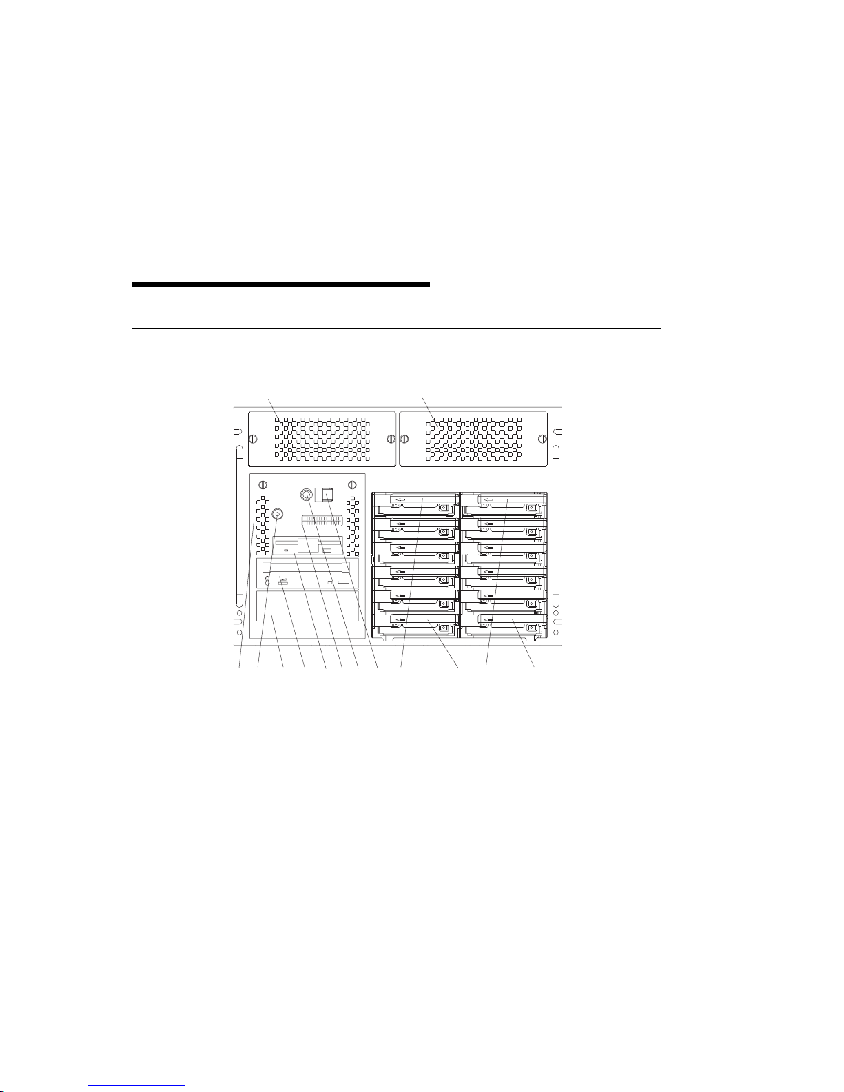
System Unit Locations
Front View with Covers Off (Model H50 and Model H70)
1
2
C
disc
10
13
12
14
1 Media Blower (Hot-Swappable) 8 Reset Button
2 DASD Blower (Hot-Swappable) 9 Operator Panel Display
3 Hot-Swappable Disk Drive D1 10 Diskette Drive
4 Hot-Swappable Disk Drive D6 11 CD–ROM Drive
5 Hot-Swappable Disk Drive C1 12 Additional Media Bay
6 Hot-Swappable Disk Drive C6 13 Power On LED
7 Power Button 14 Optional SCSI Boot Disk (behind Op Panel
11
8
9
6
74
5
Display and LEDs)
D
3
Chapter 1. Reference Information 1-1
Page 18
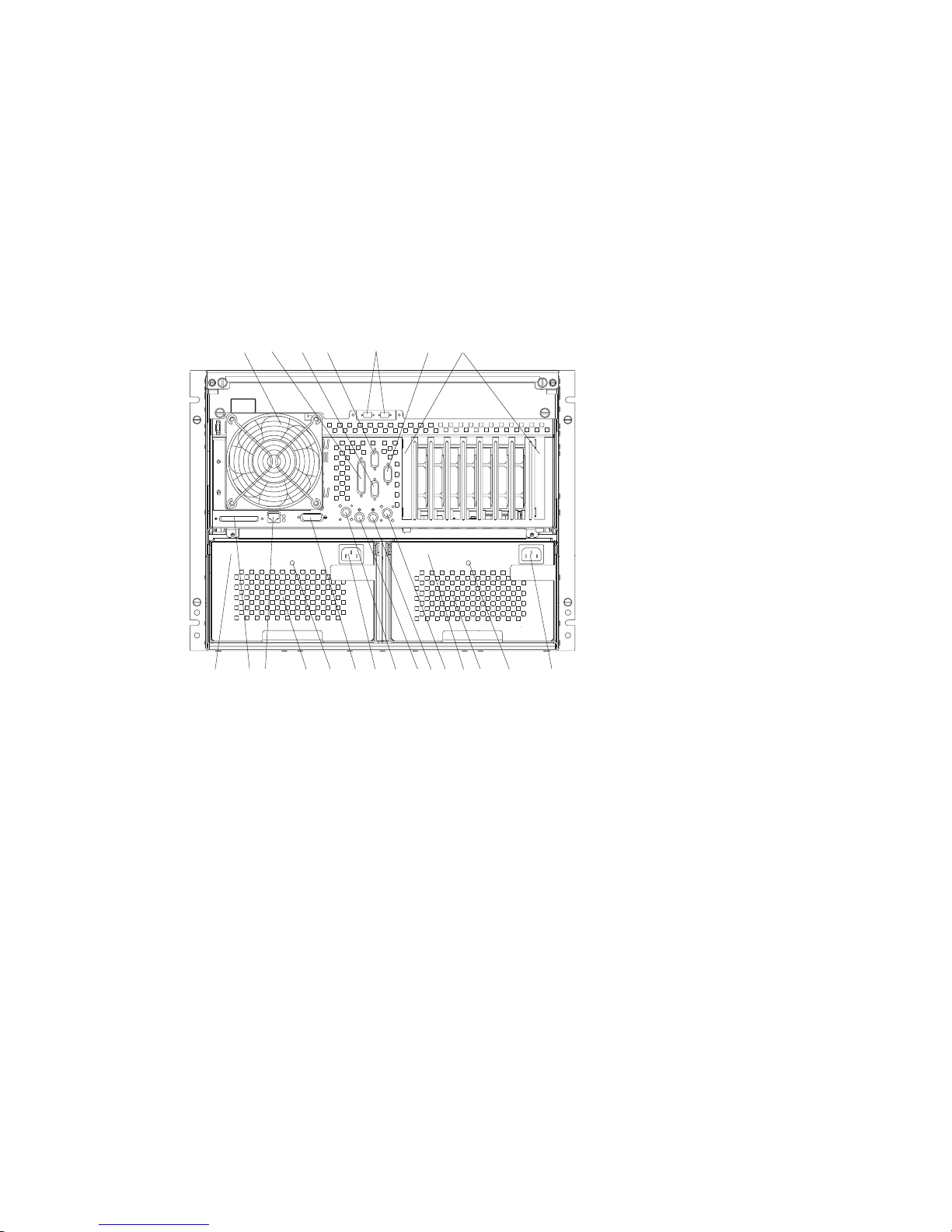
Rear View Model H50
1
2
4
3
5
1P 2P 3P 4P 5P 6P 7P 8P/I 9P/I
7
6
21
20
22
1 CPU Fan 12 Power Control Interface Connector
2 Parallel Connector 13 Mouse Connector
3 Serial Connector(S2) 14 Keyboard Connector
4 Serial Connector(S1) 15 Power Control Interface Connector
5 External SSA Connectors (Optional) 16 Power Connector for First Power Supply
6 Serial Connector(S3) 17 AUI Ethernet Connector
7 I/O Slots 18 First Power Supply Status LED
8 Power Connector for Second Power
Supply
9 Second Power Supply Status LED 20 RJ45 Ethernet Connector
10 Internal Fans for Second Power Supply 21 External SCSI Connector
11 Second Power Supply 22 First Power Supply
19
18
15
12
1117 14
19 Internal Fans for First Power Supply
9
1016 13
8
1-2 RS/6000 Enterprise Server Model H Series Installation and Service Guide
Page 19
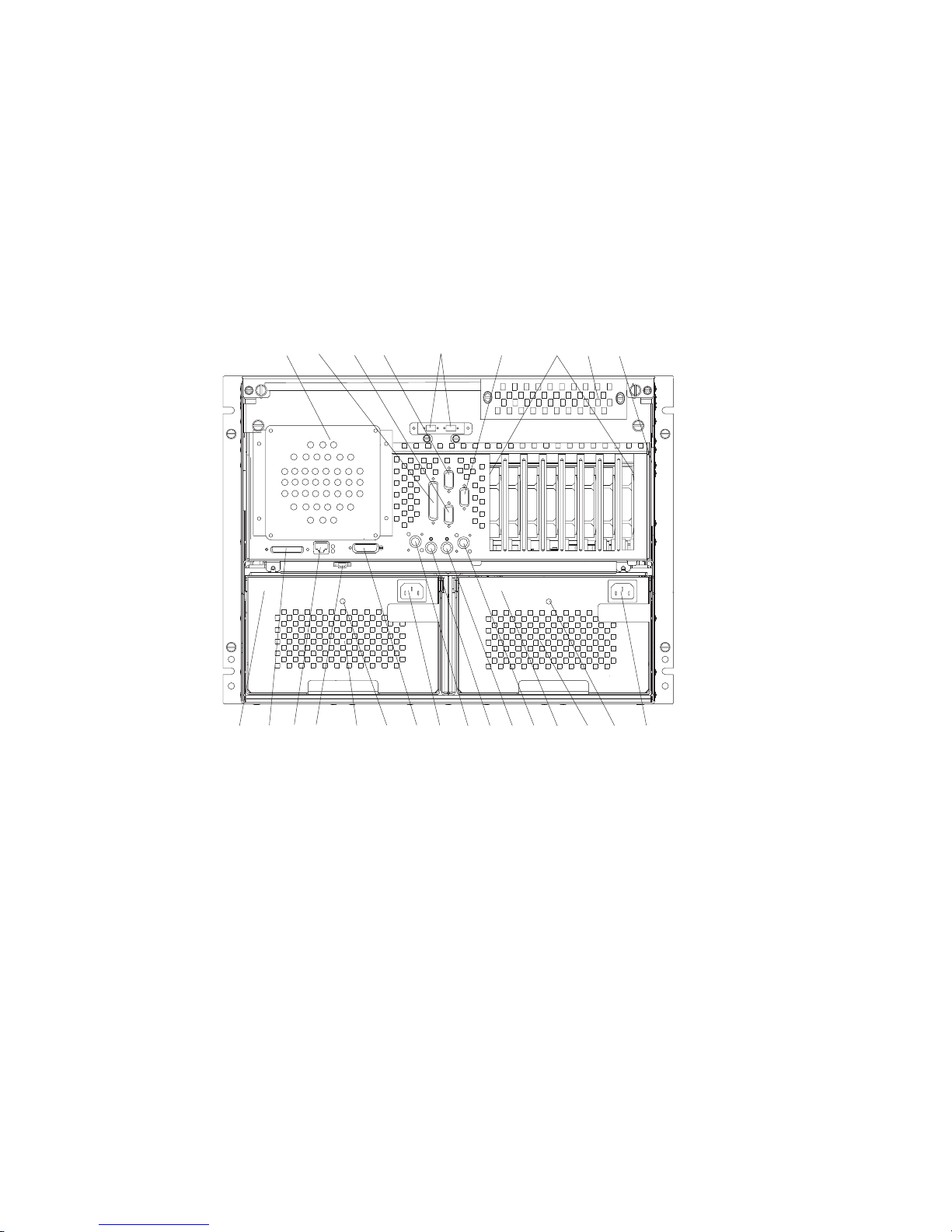
Rear View Model H70
2
4
3
5
6
1P 2P 3P 4P 5P 6P 7P 8P
7
91
8
2122232425
1 CPU Fan 14 Power Control Interface Connector
2 Parallel Connector 15 Mouse Connector
3 Serial Connector(S2) 16 Keyboard Connector
4 Serial Connector(S1) 17 Power Control Interface Connector
5 External SSA Connectors (Optional) 18 Power Connector for First Power Supply
6 Serial Connector(S3) 19 AUI Ethernet Connector
7 I/O Slots 20 First Power Supply Status LED
8 I/O Blower (Hot-Swappable) 21 Internal Fans for First Power Supply
9 I/O Blower Connector 22 CPU Fan Connector
10 Power Connector for Second Power
Supply
11 Second Power Supply Status LED 24 External SCSI Connector
12 Internal Fans for Second Power Supply 25 First Power Supply
13 Second Power Supply
19 16
20
13
23 RJ45 Ethernet Connector
1117 14
1218 15
10
Chapter 1. Reference Information 1-3
Page 20
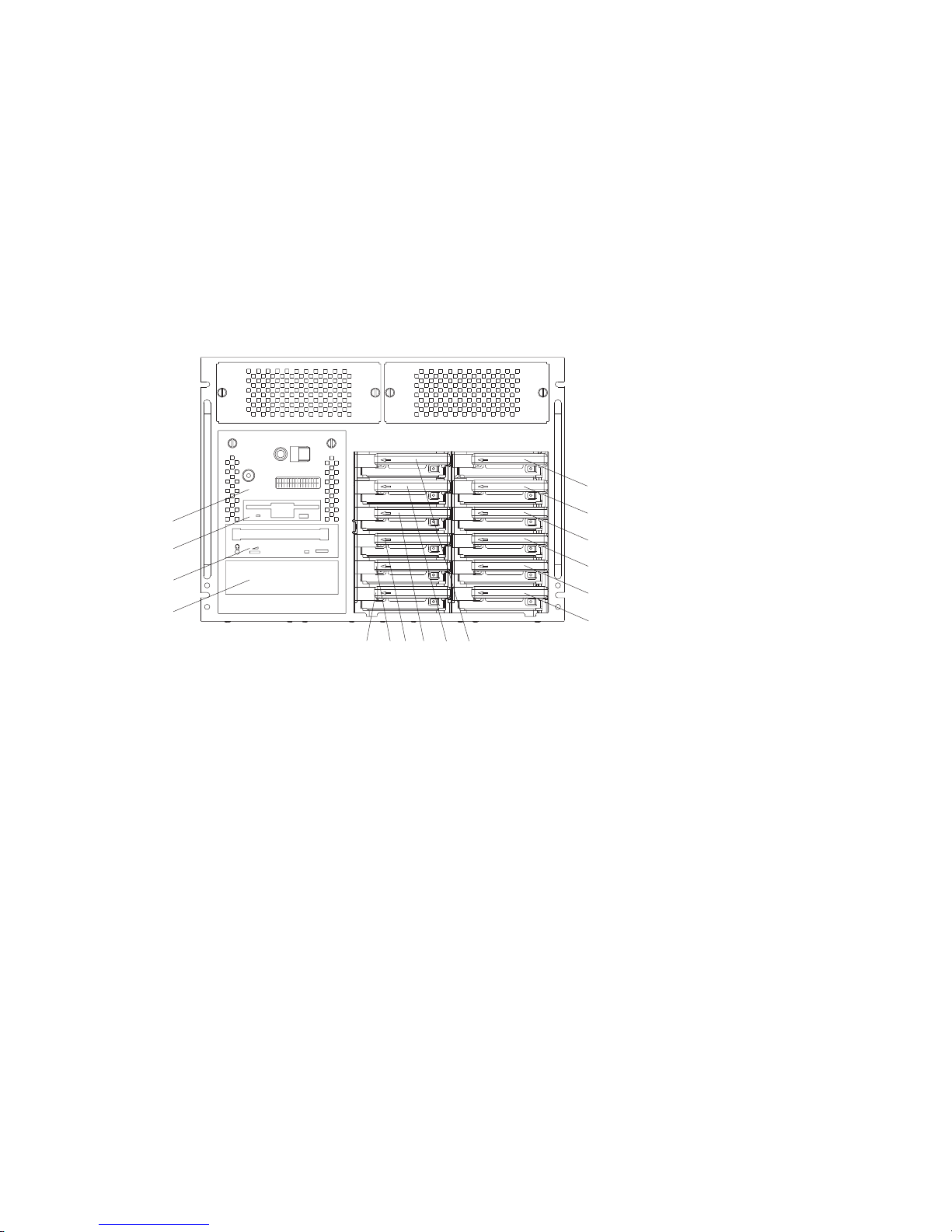
Bay Locations (Model H50 and Model H70)
D6
B2
B1
disc
A2
A1
B2 Optional SCSI Boot Disk Drive (behind
C1
C2
c
C3
C4
C5
D
C6
C5 Hot-Swappable Disk Drive
Op Panel Display)
B1 Diskette Drive C6 Hot-Swappable Disk Drive
A2 CD–ROM Drive D1 Hot-Swappable Disk Drive
A1 Media Bay (can be CD–ROM, Tape, or
D2 Hot-Swappable Disk Drive
non-hot-swappable hard disk drive)
C1 Hot-Swappable Disk Drive D3 Hot-Swappable Disk Drive
C2 Hot-Swappable Disk Drive D4 Hot-Swappable Disk Drive
C3 Hot-Swappable Disk Drive D5 Hot-Swappable Disk Drive
C4 Hot-Swappable Disk Drive D6 Hot-Swappable Disk Drive
D5
D4
D3
D2
D1
1-4 RS/6000 Enterprise Server Model H Series Installation and Service Guide
Page 21

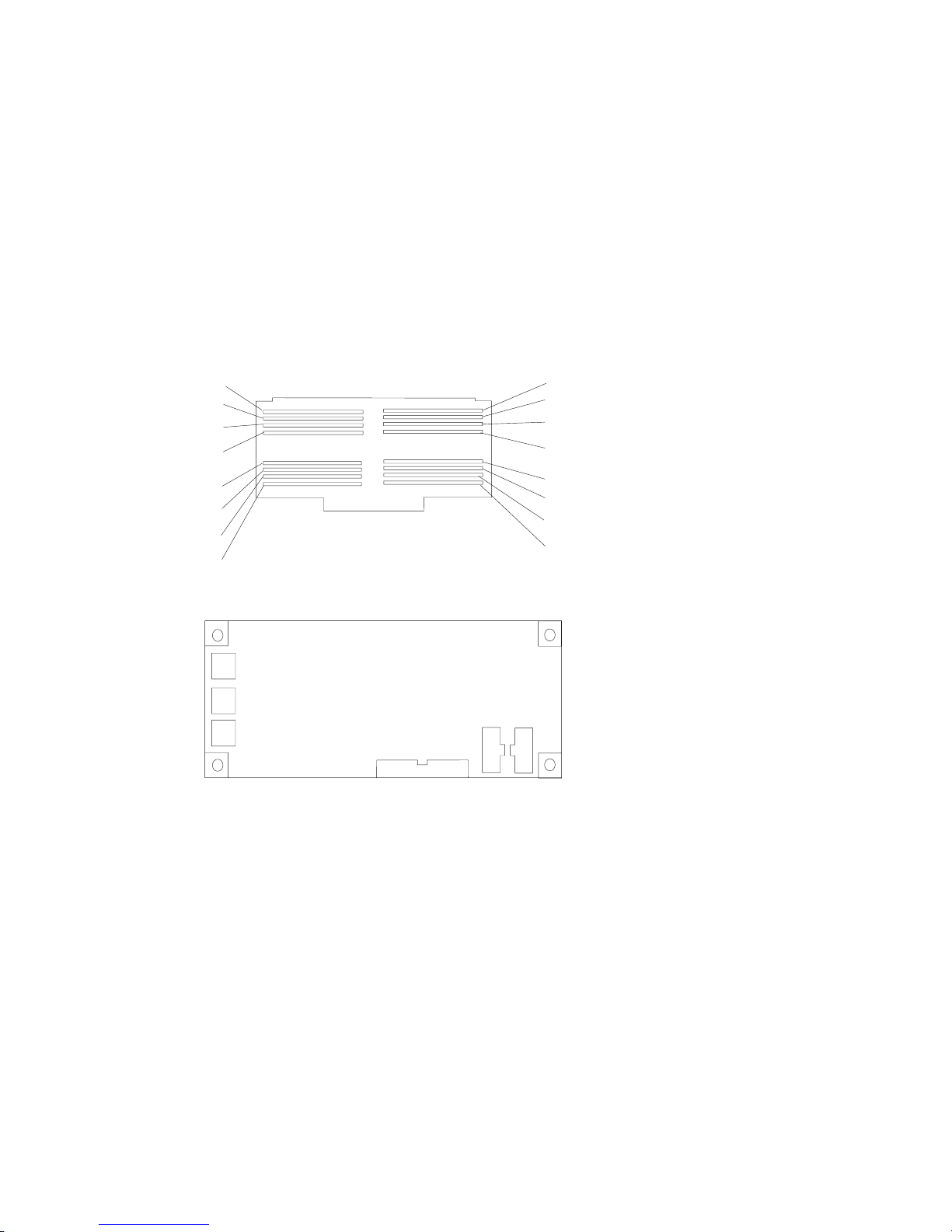
I/O Board Locations Model H50
J43
J22A
J19
J15
J51
J13
J17
J12
J9I
Shared ISA/PCI
J9P
Slots
J8I
J8P
J7
J6
PCI Slots
J5
J4
J3
J2
64 Bit
J1
PCI Slots
J25
J26
J16
P2
P1
J1, J2 64-bit PCI connectors J3, J4, J5,
J8I, J9I ISA connectors J10 Service Processor
J11 External SCSI connector J12 Not Used
J13 Diskette Drive connector J15 Not Used
J16 SCSI Security Jumper J17 Not Used
J18 Ethernet connector (thick) J19 Not Used
J21 Ethernet connector (twisted pair) J22A Operator Panel
J23 Keyboard connector J25 Internal SCSI connector (port 1)
J26 System board connector J27 Mouse connector
J30 Internal SCSI connector (port 2) J41 Serial connector (serial port 1 and 2)
J43 Battery Socket J47 Parallel connector
J50 Serial connector (serial port 3) P1, P2 Power Supply
J51 Fan Monitor Control (FMC) card
J50
J41
J47
J6, J7, J8P,
J9P
J27
J23
J18
J30
J21
J11
J10
32-bit PCI connectors
Chapter 1. Reference Information 1-5
Page 22

I/O Board Locations Model H70
J16
J15
J14
J13
J12
J27
J11
J1, J3 SCSI Port 2 connector J2 Ethernet connector (twisted pair)
J4 Ethernet connector (thick) J5 Parallel port
J6 Serial ports 1 and 2 J7 Serial port 3
J8 Keyboard port J9 Mouse port
J10 System board connector J11 Power supply
J12 SCSI port 1 connector J13 Diskette drive connector
J14 Operator panel connector J15 Power supply
J16 Power supply J17, J18,
J19, J20,
J22, J24
J29 DASD backplane connectors
32-Bit PCI connectors J27 Fan monitor card connector
J29
J10
J21, J23
J7
J6
J5
J3
J24
J23
J22
J21
J20
J19
J18
J17
J9
J8
J4
J2
J1
64-Bit PCI connectors
1-6 RS/6000 Enterprise Server Model H Series Installation and Service Guide
Page 23
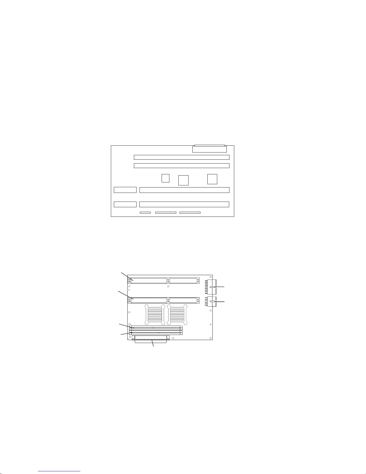
System Board Locations Model H50
J13
J12
J9
J6
J5, J6 Processor card connector #2 J8, J9 Processor card connector #1
J12 Memory card connector #1 J13 Memory card connector #2
J8
J5
System Board Locations Model H70
J
8
7
J
6
J3
J
2
J1
J
5
J
J8 Processor card connector #2 J6 Processor card connector #1
J3 Memory card connector #1 J2 Memory card connector #2
J7 3.3V Power J5 5.0V Power
J1 Connector to I/O board
Chapter 1. Reference Information 1-7
Page 24
Memory Card and Memory Module Locations
Slot J15
Slot J13
Slot J11
Slot J9
Slot J7
Slot J5
Slot J3
Slot J1
Fan Monitor Control (FMC) Card
J2
J4
J3
Model H50
J5
J1
Slot J16
Slot J14
Slot J12
Slot J10
Slot J8
Slot J6
Slot J4
Slot J2
J6
J2 Fan 5 (Hot-Swappable Media Blower) J5 Power Supply and Fans 1, 2, 3, 4 (Power
J4 Fan 6 (Hot-Swappable DASD Blower) J1 To I/O Board
J3 Fan 7 (CPU Fan) J6 To PCI Connectors
Model H70
J2 Fan 5 (Hot-Swappable Media Blower) J5 Power Supply and Fans 1, 2, 3, 4 (Power
J4 Fan 6 (CPU Fan) J1 To I/O Board
J3 Fans 7 and 8 (Hot-Swappable I/O and
DASD Blower)
1-8 RS/6000 Enterprise Server Model H Series Installation and Service Guide
Supply Fan Assemblies)
Supply Fan Assemblies)
J6 To PCI Connectors
Page 25

Model H50 Cable Diagram
Display
J22A
OP Panel
Diskette
DASD Backplane
Power Control Inf
J6
J13
J1
J52
J5
FMC
J51
J25
J5
J8
J9
J6
SCSI
4-Drop
CPU Fan
J3
J4
J2
DASD Blower
Media Blower
J9
J7
J1
Power Supply 1
30 Amp Wall Cord
Media Bays
Diskette
CD-ROM
Optional
Chapter 1. Reference Information 1-9
J10
J4
Power Distribution Board
Power Distribution Bus
J3
J8
J6
Power Supply 2
J5
J2
1x4
J1
J2
DASD Bay 1
1x4
J1
J2
DASD Bay 2
Page 26

Model H70 Cable Diagram
Display
I/O Board
6
1
J
J1
OP Panel
Diskette
DASD Backplane
Power Control Inf
System
Board
J27
9
2
J
J5
5
J14
J12
J13
J11
J7
SCSI
4-Drop
I/O Blower
J5
J6
J1
FMC
J3
J4
J2
DASD Blower
Media Blower
CPU Fan
J9
J1
J7
J10
J4
Power Distribution Board
Power Supply 1
30 Amp Wall Cord
Power Distribution Bus
Media Bays
Diskette
CD-ROM
Optional
1-10 RS/6000 Enterprise Server Model H Series Installation and Service Guide
J3
J8
J6
Power Supply 2
J5
J2
1x4
J1
J2
DASD Bay 1
1x4
J1
J2
DASD Bay 2
Page 27
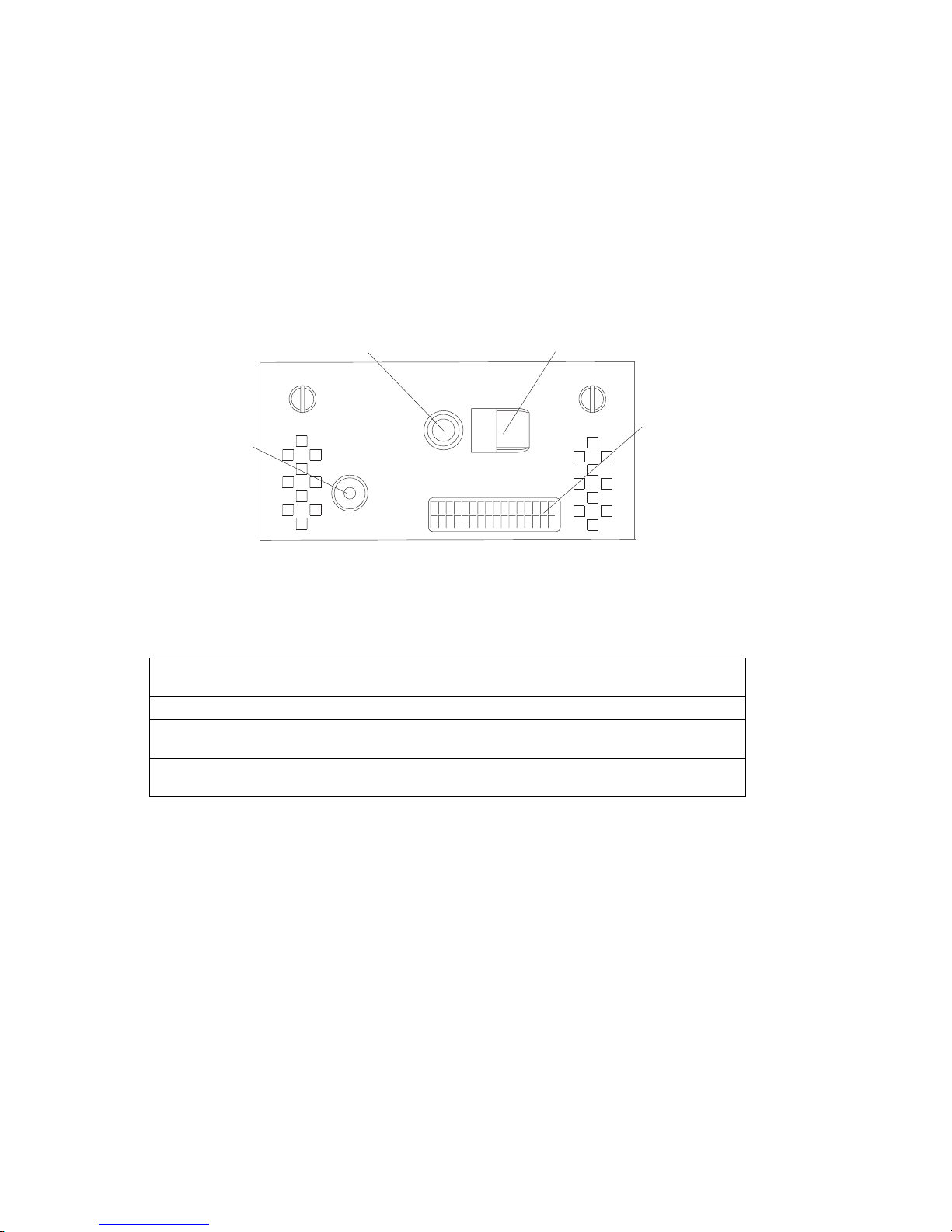
Operator Panel
1
4
1 Reset Button 3 Operator Panel Display
2 Power On Button 4 Power On LED
2
LED Indicator Status
3
State of LED Operator Panel LED First Power Supply
LED
Off No AC power No AC power No AC power
On, blinking
green
On, steady
green
System plugged in, not
turned on
System plugged in and
turned on
System plugged in, not
turned on
System plugged in and
turned on
Second Power Supply
LED
System plugged in, not
turned on
System plugged in and
turned on
Chapter 1. Reference Information 1-11
Page 28

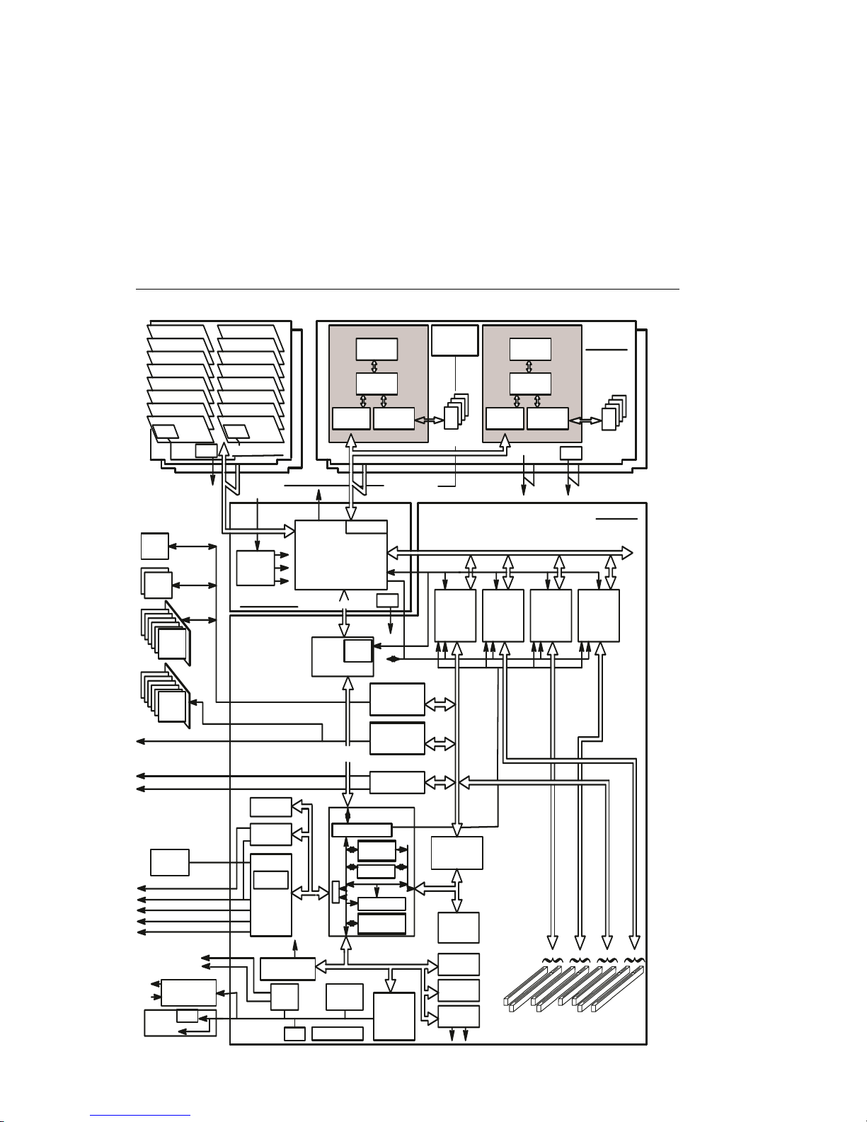
CPU Drawer Data Flow Model H50
64 MB ± 3 GB
2 ± 32 DIMMS
(SDRAMS)
(16 & 64 Mbit)
Hot Plug
DASD
MEDIA
CDROM
Hot Plug
DASD
Fan Monitoring and
7
Fans
Control (FMC) card
Op±Panel
Diskette
J±Tag
VPD
2
I C
L2 Cache
8±way Set Assoc
Memory Card
83 MHZ
Core Memory
System
Controller
(Data Transfer Engine)
Clock
System Board
IPLROS
(1 MB)
System Specific
Gate Array
Internal SCSI
Ethernet Adapter Unit Interface (AUI)
Ethernet Twisted Pair
External/ Internal SCSI
Env Sensors
VPD
Service
Processor
Connector
Keyboard
Mouse
Serial
P1284
(Parallel)
Serial (2)
Rajah ASIC
SP ±Bus
80C42
Serial Port
Super I/O
National
87332
604e
332 MHZ 332 MHZ
60X 2Word
166 MHZ
Control
166 MHZ
Master
Oscillator
Cache
RAM
256 KB
6XX 4Word4Word
83 MHZ
604e
L2 Cache
Control
8±way Set Assoc
J±TAG
6XX±MX Bus
64 Addr/Data/Data
50 MHz
Arbitration
VPD
BusID 0
I2C
PCI32±A PCI32±B PCI64±C
POR Config
X±Bus
SSC
BUFFER
ETHERNET ADAPTER
BUFFER/MUX
BUFFER
SCSI ADAPTER
NCR 53C825A
AMD79C970
SCSI ADAPTER
NCR 53C825A
MPIC2A
TOD
NVRAM
PCI to ISA
PCI Bus A
ISA Bus
PCI Feature Slots 64 Bit PCIShared ISA Slots
87 6 5 4 3 2 19
Processor Card
60X 2Word
166 MHZ X5 ChipX5 Chip
166 MHZ
BusID 2 BusID 1
32 Bit /
33 Mhz
PCI Bus B
Cache
RAM
256 KB
VPD
I2C
I/O Board
32 Bit /
33 Mhz
PCI Bus C
64 Bit /
33 Mhz
(50 Mhz)
1-12 RS/6000 Enterprise Server Model H Series Installation and Service Guide
Page 29
CPU Drawer Data Flow Model H70
VPD
64 MB-8GB
2-32 DIMMS
CD
ROM
Media
Hot
Plug
DASD
Hot
Plug
DASD
Diskette
Serial
Serial (2)
Parallel
Mouse
Keyboard
I2C to
Power Supplies
Fans
Fan Monitor
VPD
Op-Panel
VPD
I2C
VPD
Memory Card
4Word
85 MHz
System
Clock
System Board
Internal SCSI
External/Internal SCSI
Ethernet Adapter
Unit Intf (AUI)
Ethernet Twisted Pair
NVRAM
(128KB)
Dual
UART
RTC
Extended
Shared
ISA Bus
J-Tag
J-Tag
Controller
I2C
Hub
VPD
8Word
6XX
Intf
J-Tag
6XX-Arb
Memory
Controller
SSGA Bus
MX
Arb
Extended
SSGA Bus
Sys Cntl Regs
Service Processor Bus
Power
Control
Env Sensors
Processor
Memory
Manager
L2 Cache
Controller
VPD
I2C
Ultra
SCSI
Adapter
Ultra2
SCSI
Adapter
Ethernet
Adapter
Sys Cntl
Regs
ISA Regs
Arbitration
SP Local
Regs
Service
Processor
8Word
6XX 4 Word
85 MHz
Arbitration
J-Tag
ISA Bus
Master
Oscillator
37.04 MHz
L2 Cache
RAM 4 MByte
Bus Id0
POR
Config
PCI to ISA
IPL ROS
(1MB)
SRAM
(512 KB)
EEPROM
(1 MB)
Debug
Port
X-I2C
PCI
Bus0
32 Bit
33 Mhz
Serial
Processor
8Word
Memory
Manager
6XX
Intf
J-Tag
6XX-MX Bus
64 Addr/Data
66 MHz
Bus Id1
PCI
Bus1
32/64 Bit
33 Mhz
8
7
PCI Feature Slots
L2 Cache
Controller
Bus Id2
6
5
VPD
I2C
PCI
Bus2
32/64 Bit
33 Mhz
4
Processor
Card
8Word
L2 Cache
RAM 4 MByte
Bus Id3
1
2
3
I/O Board
PCI
Bus3
32/64 Bit
33 Mhz
Chapter 1. Reference Information 1-13
Page 30

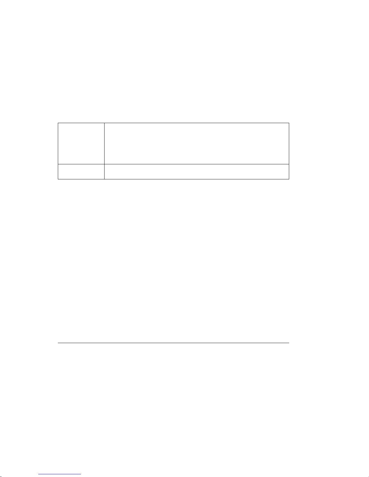
Specifications
The mechanical packaging, cooling, power supply, and environmental requirements
for the server is shown in the following:
Dimensions
Height
Width
Depth (H50)
Depth (H70)
Weight
Empty
Maximum Configuration
Electrical
Power source loading typical in kVA
Power source loading maximum in kVA
Voltage range (V ac)
Frequency (hertz)
Thermal output (typical)
Thermal output (maximum)
Power requirements (typical)
Power requirements (maximum) Model H50
Power requirements (maximum) Model H70
Power factor
Inrush current
Maximum altitude
Temperature Requirements Operating
10 to 40°C
(50 to 104°F)
Humidity Requirements
(Noncondensing)
Wet Bulb
Noise Emissions
L
WAd
L
pAm
<LpA>
m
Impulsive or prominent
discrete tones
Clearances Front Back Left Right
Service 1650 mm(65 in) 1015 mm(40 in) 915 mm (36 in) 915 mm (36 in)
Install/Air
Flow
Maintenance of a proper service clearance will allow proper air flow.
Operating
8% to 80%
23°C (73°F)
Operating
6.2 bels
350 mm
443 mm
844 mm
875 mm
71 kg
89 kg
200 to 240 (autoranging)
50 or 60
975 BTU/hr
2460 BTU/hr
285 watts
600 watts
750 watts
0.8 - 0.96
50 amps
2135m (7000 ft.)
NA
43 dBA
No
13.8 in.
8 (EIA units)
17.4 in.
33.2 in.
34.2 in.
157 lbs.
195 lbs.
0.52
0.56
Non-Operating
(Shipping) (Ambient)
1 to 52°C 10 to 43°C
(34 to 125°F) (50 to 110°F)
Non-Operating
8% to 80%
27°C (80°F)
Idle
6.0 bels
N/A
40 dBA
No
1-14 RS/6000 Enterprise Server Model H Series Installation and Service Guide
Page 31

Power Cables
To avoid electrical shock, a power cable with a grounded attachment plug is provided. Use only properly grounded outlets.
Power cables used in the United States and Canada are listed by Underwriter's Laboratories (UL) and certified by the Canadian Standards Association (CSA). These
power cords consist of:
Electrical cables, Type SVT or SJT
Attachment plugs complying with National Electrical Manufacturers Association
(NEMA) 5-15P.
"For 230 V operation in the United States use a UL listed cable set consisting of a
minimum 18 AWG, Type SVT or SJT three-conductor cable a maximum of 15 feet in
length, and a tandem blade, grounding type attachment plug rated at 15 A, 250 V."
Appliance couplers complying with International Electrotechnical Commission
(IEC) Standard 320, Sheet C13
Power cables used in other countries consist of the following:
Electrical cables, Type HD21
Attachment plugs approved by the appropriate testing organization for the spe-
cific countries where they are used.
"For units set at 230 V (outside of U.S.): use a cable set consisting of a minimum 18
AWG cable and grounding type attachment plug rated 15 A, 250 V. The cable set
should have the appropriate safety approvals for the country in which the equipment
will be installed and should be marked HAR'."
Refer to Chapter 8 on page 8-1 to find the power cables that are available.
Chapter 1. Reference Information 1-15
Page 32

Service Inspection Guide
Perform a service inspection on the system when:
The system is inspected for a maintenance agreement.
Service is requested and service has not recently been performed.
An alterations and attachments review is performed.
Changes have been made to the equipment that may affect its safe operation.
External devices with their own power cables have those cables attached.
If the inspection indicates an unacceptable safety condition, the condition must be
corrected before anyone can service the machine.
Note: The correction of any unsafe condition is the responsibility of the owner of the
system.
Perform the following checks:
1. Check the covers for sharp edges and for damage or alterations that expose the
internal parts of the system unit.
2. Check the covers for proper fit to the system unit. They should be in place and
secure.
3. Gently rock the system unit from side to side to determine if it is steady.
4. Set the power switch of the system unit to Off.
5. Remove the covers.
6. Check for alterations or attachments. If there are any, check for obvious safety
hazards such as broken wires, sharp edges, or broken insulation.
7. Check the internal cables for damage.
8. Check for dirt, water, and any other contamination within the system unit.
9. Check the voltage label on the back of the system unit to ensure that it matches
the voltage at the outlet.
10. Check the external power cable for damage.
11. With the external power cable connected to the system unit, check for 0.1 ohm
or less resistance between the ground lug on the external power cable plug and
the metal frame.
1-16
RS/6000 Enterprise Server Model H Series Installation and Service Guide
Page 33

12. Perform the following checks on each device that has its own power cables:
a. Check for damage to the power cord.
b. Check for the correct grounded power cable.
c. With the external power cable connected to the device, check for 0.1 ohm or
less resistance between the ground lug on the external power cable the
metal frame of the device.
13. Install the covers.
Chapter 1. Reference Information 1-17
Page 34

1-18 RS/6000 Enterprise Server Model H Series Installation and Service Guide
Page 35

Chapter 2. Maintenance Analysis Procedures (MAPs)
Entry MAP
Use the following table to determine your starting point.
Note: When possible, run Online Diagnostics in Service Mode. Online Diagnostics
perform additional functions, compared to Standalone Diagnostics. This ensures that
the error state of the system is captured in NVRAM for your use in fixing the
problem. The AIX error log and SMIT are only available when diagnostics are run
from the hard drive.
Notes:
1. If more than eight digits are displayed in the operator panel, use only the first
eight digits to find the error in the tables. The digits that display beyond the first
eight digits are location codes that can assist you in diagnosing the problem. See
“Location Codes” on page 3-68.
2. Licensed programs frequently rely on network configuration, and system information stored on the VPD on the operator panel control assembly (connector U2).
If the MAPs indicate that the Operator Panel Control Assembly should be
replaced, swap the VPD from the old operator panel to the new one. If the old
VPD module has to be replaced call technical support for recovery instructions.
If recovery is not possible, notify the system owner that new keys for licensed
programs may be required.
3. If a network adapter or the I/O board is replaced, the network administrator must
be notified so that the client IP addresses used by the server can be changed.
In addition, the operating system configuration of the network controller may
need to be changed in order to enable system startup. Ensure that all clients or
servers that address this system are updated.
Symptom Action
You have parts to exchange or a corrective
action to perform.
You need to verify that a part exchange or corrective action corrected the problem.
You need to verify correct system operation. Go to MAP 420: System Checkout in the
Chapter 2. Maintenance Analysis Procedures 2-1
Service Actions
1. Go to the Removal and Replacement Procedures.
2. Go to MAP 410: Repair Checkout in the
Diagnostic Information for Multiple Bus
Systems.
Go to MAP 410: Repair Checkout in the
Diagnostic Information for Multiple Bus Systems.
Diagnostic Information for Multiple Bus Systems.
Page 36

Symptom Action
Symptom Analysis
You have OK displayed The Service Processor (SP) is ready. The
system is waiting for power on.
You have STBY displayed The Service Processor (SP) is ready. The
system was shutdown by the operating system
and is still powered on. This condition can be
requested by a privileged system user with no
faults. See SP error log for possible operating
system fault indications.
You do not have a determined symptom. Go to “MAP 1020: Problem Determination” on
page 2-5.
You have an 8-digit error code displayed. Record the error code. Go to Chapter 3 on
page 3-1.
You have an SRN. Go to the Fast Path MAP in the Diagnostic
Information for Multiple Bus Systems.
The system POST indicators are displayed on
the system console, the system pauses and
then restarts. The term "POST indicators" refer
to the icons (graphic display) or device mnemonics (ASCII terminal) that appear during the
power-on self-test (POST).
The system stops and POST indicators are displayed on the system console. The term "POST
indicators" refer to the icons (graphic display) or
device mnemonics (ASCII terminal) that appear
during the power-on self-test (POST).
The system stops and the message "STARTING
SOFTWARE PLEASE WAIT..." is displayed on
Go to “Boot Problems and Concerns” on
page 3-65.
1. Use MAP 1540 to isolate the problem.
Go to “Checkpoints” on page 3-44.
ASCII terminal, the boot indicator ( ) is
displayed on a graphics terminal.
The system does not respond to the password
being entered or the system login prompt is displayed when booting in service mode.
2-2 RS/6000 Enterprise Server Model H Series Installation and Service Guide
Verify that the password is being entered from
the ASCII terminal or keyboard defined as the
system console. If so, then the keyboard or its
controller may be faulty.
1. If entering the password from the keyboard
which is attached to the system, replace the
keyboard. If replacing the keyboard does not
fix the problem, replace the I/O board. (See
notes on 2-1.)
2. If entering the password from a keyboard
which is attached to a ASCII terminal,
suspect the ASCII terminal. Use the
Problem Determination Procedures for the
terminal. Replace the I/O board if these procedures do not reveal a problem.
Page 37

Symptom Action
The power light on the operator panel does not
start flashing within 30 seconds of A/C power
application, or the power light on the operator
panel is flashing but the operator panel is blank.
The power light does not come on, or stay on. Go to “MAP 1520: Power” on page 2-19.
The power light on the operator panel is on, but
nothing is displayed on the system console, and
the operator panel is blank.
All display problems. 1. If using a graphics display, go to the
888 is displayed in the control panel followed by
additional error codes.
The system stops and a 4-digit number is displayed in the operator panel display.
Go to “MAP 1520: Power” on page 2-19.
1. If using a graphic display, go to the Problem
Determination Procedures for the display.
2. If you do not find a problem then replace the
display adapter.
3. Go to “MAP 1540: Minimum Configuration”
on page 2-37.
Problem Determination Procedures for the
display.
2. If you do not find a problem then replace the
display adapter.
3. If the problem is with the ASCII terminal:
a. Make sure that the ASCII terminal is
connected to S1.
b. If problems persist, go to the Problem
Determination Procedures for the terminal.
4. If you do not find a problem then suspect
the I/O board. Go to “MAP 1540: Minimum
Configuration” on page 2-37.
Go to the Fast Path MAP in the Diagnostic
Information for Multiple Bus Systems.
If the number displayed begins with the character "E0xx" then go to “Model H50 Service
Processor Checkpoints” on page 3-45 or “Model
H70 Service Processor Checkpoints” on
page 3-49. If "E1xx-EFFF" is is displayed, then
go to “Firmware Checkpoints” on page 3-52.
For all other numbers record SRN 101-xxx,
where xxx is the last three digits of the four-digit
number displayed in the operator panel, then go
to the Fast Path MAP in the Diagnostic Informa-
tion for Multiple Bus Systems.
Note: If the operator panel displays 2 sets of
numbers, use the bottom set of numbers as the
error code.
Chapter 2. Maintenance Analysis Procedures 2-3
Page 38

Symptom Action
No codes are displayed on the operator panel
within a few seconds of turning on the system.
The operator panel is blank before the system is
powered on (operator panel should display OK).
The SMS configuration list or Boot sequence
selection menu shows more SCSI devices
attached to a controller/adapter than are actually
attached.
You cannot load diagnostics. Go to “MAP 1020: Problem Determination” on
You have a problem that does not prevent the
system from booting.
You suspect a cable problem. See the RS/6000 Adapters, Devices, and Cable
Reseat the operator panel cable.
If problem not resolved, replace in order:
1. Operator Panel Control Assembly. Remove
the VPD module from the old Operator
Panel Control Assembly (connector U2) and
place in the new one.
2. I/O board (See notes on 2-1.)
A device may be set to use the same SCSI bus
ID as the control adapter. Note the ID being
used by the controller/adapter (this can be
checked and/or changed via an SMS utility), and
verify that no device attached to the controller is
set to use that ID.
If settings do not appear to be in conflict:
1. Replace the SCSI cable.
2. Replace the device.
3. Replace the SCSI adapter (or I/O board if
connected to one of the two integrated SCSI
controllers on the I/O board). (See notes on
2-1 if the I/O board is replaced.)
Note: In a "Twin-tailed" configuration where
there is more than one initiator device
(normally another system) attached to
the SCSI bus, it may be necessary to
change the ID of the SCSI controller or
adapter with the System Management
Services.
page 2-5.
Go to the Fast Path MAP in the Diagnostic
Information for Multiple Bus Systems.
Information for Multiple Bus Systems.
You Cannot Find the Symptom in this Table
All other problems. Go to “MAP 1020: Problem Determination” on
2-4 RS/6000 Enterprise Server Model H Series Installation and Service Guide
page 2-5.
Page 39

MAP 1020: Problem Determination
Purpose of This MAP
Use this MAP to get an error code if you were not provided one by the customer or
you are unable to load diagnostics. If you are able to load the diagnostics, go to
MAP 0020 in the Diagnostic Information for Multiple Bus Systems.
The Service Processor may have recorded one or more symptoms in its error log. It
is a good idea to examine that error log before proceeding (see Service Processor
System Information Menu).
The Service Processor may have been set by the user to monitor server operations
and to attempt recoveries. You may wish to disable these actions while you diagnose
and service the system. If you disable them, you should make notes of their current
settings for restoration before you leave. Following are the settings of your interest.
Surveillance From the Service Processor Setup Menu, go to
the Surveillance Setup Menu and disable surveillance.
Unattended Start From the Service Processor System Power
Control Menu, disable unattended start mode.
Reboot Policy From the System Power Control Menu, go to
the Reboot/Restart Policy Setup Menu and set:
1. Number of reboot attempts to 0 (zero)
2. Use OS-Defined restart policy to No
3. Enable supplemental restart policy to No.
Call Out From the Call-In/Call-Out Setup Menu, go to the
Serial Port Selection Menu and disable call-out
on both serial ports.
Be prepared to record code numbers and use those numbers in the course of analyzing a problem. Go to “Step 1020-1.”
Step 1020-1
The following steps analyze a failure to load the diagnostic programs.
Note: You are asked questions regarding the operator panel display. You are also
asked to perform certain actions based on displayed POST indicators.
Please be observant of these conditions.
Chapter 2. Maintenance Analysis Procedures 2-5
Page 40

1. Insert the diagnostic CD-ROM into the CD-ROM drive.
2. Turn the power off.
3. Turn the power on.
4. When the keyboard indicator is displayed (the word keyboard on an ASCII terminal or the keyboard icon on a graphical display), press the F5 key on the
directly-attached keyboard or the number 5 key on an ASCII terminal.
5. Enter any requested passwords.
6. Wait until the diagnostics are loaded or the system appears to stop.
7. Find your symptom in the following table; then follow the instructions given in the
Action column.
Symptom Action
The diskette LED is blinking rapidly, or EIEA or
EIEB is displayed on the operator panel.
The system stops with a prompt to enter a password.
The diagnostic operating instructions are displayed.
The system login prompt is displayed. You may not have pressed the correct key or
The system does not respond when the password is entered.
The flash EPROM data is corrupted. The
recovery procedure for the flash EPROM should
be executed. See “System Firmware Recovery”
on page 6-24.
Enter the password. You are not allowed to continue until a correct password has been entered.
When you have entered a valid password go to
the beginning of this table and wait for one of
the other conditions to occur.
Go to MAP 0020 in the Diagnostic Information
for Multiple Bus Systems.
you may not have pressed the key soon enough
when you were to indicate a Service Mode IPL
of the diagnostic programs. If this was the case
start over at the beginning of this Step.
Note: Perform the systems shutdown proce-
dure before turning off the system.
If you are sure you pressed the correct key in a
timely manner, go to “Step 1020-2” on
page 2-8.
Go to “Step 1020-2” on page 2-8.
2-6 RS/6000 Enterprise Server Model H Series Installation and Service Guide
Page 41

Symptom Action
The system stopped and a POST indicator is
displayed on the system console and an eightdigit error code is not displayed.
The system stops and a 4-digit number is displayed in the operator panel display.
The System Management Services is diaplayed. Go to “Step 1020-4” on page 2-9.
All other symptoms. If you were directed here from the Entry MAP,
If the POST indicator represents:
memory, record error code M0MEM002.
keyboard, record error code M0KBD000.
SCSI, record error code M0CON000.
network, record error code M0NET000.
speaker (audio), record error code
M0BT0000.
Go to “Step 1020-3” on page 2-8.
If the number displayed begins with the char-
acter "E0xx" then go to “Model H50 Service
Processor Checkpoints” on page 3-45 or “Model
H70 Service Processor Checkpoints” on
page 3-49. If "E1xx-EFFF" is displayed, then go
to “Firmware Checkpoints” on page 3-52.
For all other numbers record SRN 101-xxx,
where xxx is the last three digits of the four-digit
number displayed in the operator panel, then go
to the Fast Path MAP in the Diagnostic Informa-
tion for Multiple Bus Systems.
Note: If the operator panel displays 2 sets of
numbers, use the bottom set of numbers as the
error code.
go to “MAP 1540: Minimum Configuration” on
page 2-37. Otherwise, find the symptom in the
“Entry MAP” on page 2-1.
Chapter 2. Maintenance Analysis Procedures 2-7
Page 42

Step 1020-2
There is a problem with the keyboard.
Find the type of keyboard you are using in the following table; then follow the
instructions given in the Action column.
Keyboard Type Action
Type 101 keyboard (U.S.). Identify by the size of
the Enter key. The Enter key is in only one horizontal row of keys.
Type 102 keyboard (W.T.). Identify by the size of
the Enter key. The Enter key extends into two
horizontal rows.
Type 106 keyboard. (Identify by the Japanese
characters.)
ASCII terminal keyboard Go to the documentation for this type of ASCII
Record error code M0KBD001; then go to
“Step 1020-3.”
Record error code M0KBD002; then go to
“Step 1020-3.”
Record error code M0KBD003; then go to
“Step 1020-3.”
terminal and continue problem determination.
Step 1020-3
Take the following actions:
1. Find the eight-digit error code in Chapter 3 on page 3-1.
Note: If the eight-digit error code is not listed in Chapter 3, look for it in the
following:
Any supplemental service manual for the device
The diagnostic problem report screen for additional information
The Service Hints Service Aid
The CEREADME file (by using the Service Hints Service Aid).
2. Perform the action listed.
2-8 RS/6000 Enterprise Server Model H Series Installation and Service Guide
Page 43

Step 1020-4
To check the error log for any errors.
Choose Utilities
Choose Error Log
If an error is logged, check the time stamp
If the error was logged during the current boot attempt, record it
Look up the error in the Chapter 3 on page 3-1 and perform the listed action
If no recent error is logged in the error log, go to “MAP 1540: Minimum
Configuration” on page 2-37.
Chapter 2. Maintenance Analysis Procedures 2-9
Page 44

MAP 1240: Memory Problem Resolution
Note:
The firmware checkpoint that sent you here could be one of the following:
E122, E213, E214, E218, E220 or E3xx
These checkpoints are referred to as "a memory checkpoint" in this MAP.
Purpose of this MAP
This MAP is used to trouble shoot a problem during the memory test when the
system stops at a memory checkpoint and no error code displays on the operator
panel.
Notes:
1. If the symptom changes while using this MAP, check for loose cards, cables, and
obvious problems. If you do not find a problem, go to “MAP 1540: Minimum
Configuration” on page 2-37.
2. The Service Processor may have recorded one or more symptoms in its error
log. It is a good idea to examine that error log before proceeding (see Service
Processor System Information Menu). Check the memory configuration in the
service processor menus. If a memory module has been deconfigured by the
system, swap the memory module positions on the memory card. The system
interprets this as an indication that the memory modules have been replaced. If
this does not work, perform the following steps:
Manually configure the memory module.
Reseat the memory card or module.
Re-ipl the system.
3. The Service Processor may have been set by the user to monitor server operations and to attempt recoveries. You may wish to disable these actions while
you diagnose and service the system. If you disable them, you should make
notes of their current settings for restoration before you leave. Following are the
settings of your interest.
Surveillance From the service Processor Setup Menu, go to the Surveillance Setup Menu
and disable surveillance.
Unattended
Start
From the Service Processor System Power Control Menu disable unattended
start mode.
2-10 RS/6000 Enterprise Server Model H Series Installation and Service Guide
Page 45
Reboot Policy From the System Power Control Menu go to the Reboot/Restart Policy Setup
Menu and set:
1. Number of reboot attempts to 0 (zero)
2. Use OS-Defined restart policy to No
3. Enable supplemental restart policy to No.
Call-Out From the Call-In/Call-Out Setup Menu, go to the Serial Port Selection Menu and
disable call-out on both serial ports.
General Memory Information
Be sure to unplug the power cable before removing or installing the memory card(s)
or memory modules to avoid damage to them.
Memory cards can be installed in either slot (or both) on the system board, there is
no requirement that one be installed before the other.
It is perfectly acceptable for there to be two partially populated memory cards in the
system, the first memory card does not have to be fully populated before memory on
the second memory card is useable.
Memory modules, on the other hand, must be installed in matched (size and speed)
pairs. Refer to "Memory Card Locations" in chapter 1 for labeling of the memory card
and "Memory Cards" in Removal and Replacement Procedures for instructions on
module removal and installation. A single memory module pair may be installed in
module slots J1 and J2 (not slots J1 and J3). A second memory module pair could
be installed in module slots J5 and J6 (slots J3 and J4 do not have to be populated
first). Along these same lines, there is no requirement that memory module slots J1
and J2 be populated before another slot pair.
Step 1240-1
1. Ensure that the diagnostics and the operating system are shut down.
2. Turn the power off.
3. Remove and re-install any installed memory card(s).
4. Turn the power on.
Does the system stop with a memory checkpoint displayed on the operator
panel?
Chapter 2. Maintenance Analysis Procedures 2-11
Page 46

NO Re-seating the memory card(s) has corrected the problem.
Go to "Map 0410: Repair Checkout" in the Diagnostic Information for Mul-
tiple Bus Systems.
YES If there is only one memory card installed tag it as "suspect bad" and go
to “Step 1240-7” on page 2-15.
If there are two memory cards installed go to “Step 1240-2” on
page 2-13.
2-12
RS/6000 Enterprise Server Model H Series Installation and Service Guide
Page 47

Step 1240-2
1. Turn the power off.
2. Remove the memory card from slot J12 (Model H50) or J3 (Model H70).
3. Turn the power on.
Does the system stop with a memory checkpoint displayed on the operator
panel?
NO Go to “Step 1240-4” on page 2-14.
YES Go to “Step 1240-3.”
Step 1240-3
1. Turn the power off.
2. Remove the memory card from slot J13 (Model H50) or J2 (Model H70).
3. Install the memory card removed from slot J12 or J3 in its original location.
4. Turn the power on.
Does the system stop with a memory checkpoint displayed on the operator
panel?
NO Tag the memory card you removed from slot J13 or J2 "suspect bad" and
go to “Step 1240-7” on page 2-15.
YES Go to “Step 1240-6” on page 2-15.
Chapter 2. Maintenance Analysis Procedures 2-13
Page 48

Step 1240-4
1. Turn the power off.
2. Remove the memory card from slot J13 (Model H50) or J2 (Model H70).
3. Install the memory card removed from slot J12 or J3 in it's original location.
4. Turn the power on.
Does the system stop with a memory checkpoint displayed on the operator
panel?
NO Go “Step 1240-5.”
YES Tag the memory card in slot J12 or J3 "suspect bad" and go to “Step
1240-7” on page 2-15.
Step 1240-5
1. Turn the power off.
2. Install the memory card removed from slot J13 or J2 in it's original location.
3. Turn the power on.
Does the system stop with a memory checkpoint displayed on the operator
panel?
NO Re-seating the memory card(s) has corrected the problem.
Go to "Map 0410: Repair Checkout" in the Diagnostic Information for Multiple Bus Systems.
YES Go to “Step 1240-6” on page 2-15.
2-14 RS/6000 Enterprise Server Model H Series Installation and Service Guide
Page 49

Step 1240-6
1. Turn the power off
2. Exchange the following FRUs in the order listed:
System board
Processor card(s)
3. Turn the power on
Does the system stop with a memory checkpoint displayed on the operator
panel?
NO Go to "Map 0410: Repair Checkout" in the Diagnostic Information for Mul-
tiple Bus Systems.
YES Reinstall the original FRU.
Repeat this step until the defective FRU is identified or all the FRUs have
been exchanged.
If the symptom did not change and all the FRUs have been exchanged,
go to “MAP 1540: Minimum Configuration” on page 2-37.
Step 1240-7
1. Turn the power off.
2. Remove all installed memory modules from the memory card you tagged
"suspect bad". Record the position of the memory modules removed so that
when instructed to re-install them they can be installed in their original position.
3. Install one pair of memory modules.
4. Turn the power on.
Does the system stop with a memory checkpoint displayed on the operator
panel?
NO If there are no more memory modules to be installed reseating the
modules on the memory card has corrected the problem.
If there was more than one pair of memory modules on the memory card
go to “Step 1240-8” on page 2-16.
YES Go to “Step 1240-9” on page 2-16.
Chapter 2. Maintenance Analysis Procedures 2-15
Page 50

Step 1240-8
1. Turn the power off.
2. Install a pair of memory modules.
3. Turn the power on.
Does the system stop with a memory checkpoint displayed on the operator
panel?
NO Repeat this step until all the memory modules are installed and tested.
If all the memory modules have been installed reseating the memory
modules on the memory card has corrected the problem.
Go to "Map 0410: Repair Checkout" in the Diagnostic Information for Mul-
tiple Bus Systems.
YES Go to “Step 1240-9.”
Step 1240-9
The failure may be caused by the last pair of memory modules installed or the
memory card. To isolate the failing FRU, do the following:
1. Turn the power off.
2. Exchange the last memory module pair installed.
3. Turn the power on.
Does the system stop with a memory checkpoint displayed on the operator
panel?
NO Go to “Step 1240-11” on page 2-18.
YES Go to “Step 1240-10” on page 2-17.
2-16 RS/6000 Enterprise Server Model H Series Installation and Service Guide
Page 51

Step 1240-10
One of the FRUs remaining in the system unit is defective.
1. Turn the power off.
2. Exchange the following FRUs in the order listed.
Memory card
System board
Processor card(s)
3. Turn the power on.
Does the system stop with a memory checkpoint displayed on the operator
panel?
NO Go to "Map 0410: Repair Checkout" in the Diagnostic Information for Mul-
tiple Bus Systems.
YES Reinstall the original FRU.
Repeat this step until the defective FRU is identified or all the FRUs have
been exchanged.
If the symptom did not change and all the FRUs have been exchanged,
go to “MAP 1540: Minimum Configuration” on page 2-37.
Chapter 2. Maintenance Analysis Procedures 2-17
Page 52

Step 1240-11
The memory module(s) (may be both) you exchanged in the previous step may be
defective. To isolate the failing memory module, do the following:
1. Turn the power off.
2. Re-install one of the memory modules you exchanged in the previous step.
3. Turn the power on.
Does the system stop with a memory checkpoint displayed on the operator
panel?
NO Repeat this step with the second memory module you exchanged in the
previous step.
If both memory modules have been tested go to "Map 0410: Repair
Checkout" in the Diagnostic Information for Multiple Bus Systems.
YES Replace the memory module.
If you have not tested both memory modules repeat this step with the
second memory module you exchanged in the previous step.
If the symptom did not change and both memory modules have been
exchanged go to “Step 1240-10” on page 2-17.
2-18
RS/6000 Enterprise Server Model H Series Installation and Service Guide
Page 53

MAP 1520: Power
Notes:
1. This is not a start of call MAP. Use this Power MAP only if you have been
directed here from a MAP step in this book or the Diagnostic Information for Mul-
tiple Bus Systems.
2. Each power supply has a test switch. If you are instructed to replace a power
supply, see “Power Supplies and Power Supply Fan Assemblies” on page 7-21.
This procedure is used to locate power problems in system units. If a problem is
detected, this procedure helps you isolate the problem to a failing unit.
Observe the following safety notice during service procedures.
DANGER
An electrical outlet that is not correctly wired could place hazardous
voltage on metal parts of the system or the devices that attach to the
system. It is the responsibility of the customer to ensure that the outlet
is correctly wired and grounded to prevent an electrical shock.
Before installing or removing signal cables, ensure that the power
cords for the system unit and all attached devices are unplugged.
When adding or removing any additional devices to or from the system,
ensure that the power cords for those devices are unplugged before the
signal cables are connected. You must disconnect all power cords from
the existing system before you add a device.
Use one hand, when possible, to connect or disconnect signal cables
to prevent a possible shock from touching two surfaces with different
electrical potentials.
During an electrical storm, do not connect cables for display stations,
printers, telephones, or station protectors for communication lines.
CAUTION:
This product is equipped with a three-wire power cord and plug for the user's
safety. Use this power cable with a properly grounded electrical outlet to avoid
electrical shock.
Chapter 2. Maintenance Analysis Procedures 2-19
Page 54

DANGER
To prevent electrical shock hazard, disconnect the power cord from the
electrical outlet before relocating the system.
CAUTION:
This system may have two power supplies installed. To reduce the risk of electrical shock, disconnect both power supply cords before servicing.
Step 1520-1
You may be directed to this MAP for several reasons:
1. The power light on the operator panel is not flashing and the operator panel is
blank.
Go to “Step 1520-2” on page 2-21.
2. The power LED on the operator panel is flashing and the operator panel is blank.
Go to “Step 1520-3” on page 2-22.
3. OK, STBY or DIAG STBY is displayed on the operator panel. There is no indication of activity when the power button on the operator panel is pressed. None
of the power LEDs light and none of the fans, including the fan in the power
supply, start to turn.
Go to “Step 1520-3” on page 2-22.
4. OK, STBY or DIAG STBY is displayed on the operator panel and the power LED
on the operator panel is flashing. When the power button on the operator panel
is pressed, the system begins to power on, but the power LED on the operator
panel does not stay on.
Go to “Step 1520-3” on page 2-22.
5. A SRN referenced in the Diagnostic Information for Multiple Bus Systems listed
MAP 1520 in the "Actions/Descriptions" column for a Voltage Sensor out of
range.
Go to “Step 1520-10” on page 2-29.
2-20 RS/6000 Enterprise Server Model H Series Installation and Service Guide
Page 55

Step 1520-2
1. Turn the power off.
2. If you have not already done so, open the rear door of the rack unit and locate
the power supplies.
3. Unplug the power cord from the Power Distribution Unit (PDU)/Power Distribution
Bus (PDB) and the power outlet.
4. Unplug the power cords from the PDU/PDB and the power supplies.
5. Check that the power cord from the power outlet to the PDU/PDB has continuity.
6. Check that the power cords from the PDU/PDB to the power supplies have continuity.
7. Check that the power outlet has been wired correctly with the correct voltage.
8. Plug the power cords into the PDU/PDB and the power supplies.
9. Plug the power cord into the PDU/PDB and the power outlet.
Did you find a problem?
NO Go to “Step 1520-3” on page 2-22.
YES Correct the problem. Go to "Map 0410: Repair Checkout" in the
Diagnostic Information for Multiple Bus Systems.
Chapter 2. Maintenance Analysis Procedures 2-21
Page 56

Step 1520-3
1. Turn the power off.
2. If you have not already done so, open the rear door of the rack unit and locate
the power supplies.
3. Unplug the power cord from the power outlet.
4. Unplug the power cord from the first (left) power supply.
5. Remove the screw from the center of the power supply handle, grasp the handle
of the power supply, pivot it upward and pull the the power supply out of the
drawer.
6. Plug the power cord into the power supply.
7. Plug the power cord into the power outlet.
Does the power LED on the power supply commence flashing within 30
seconds after applying AC power?
NO Replace the power supply.
Repeat this step for the second (right) power supply if installed.
Go to "Map 0410: Repair Checkout" in the Diagnostic Information for Mul-
tiple Bus Systems.
YES Repeat this step for the second (right) power supply if installed.
Go to “Step 1520-4” on page 2-23.
2-22 RS/6000 Enterprise Server Model H Series Installation and Service Guide
Page 57

Step 1520-4
There is a small dark-colored test switch on the side of the power supply near the
power supply connector. It is a normally off momentary switch. Press and hold this
switch for a few seconds while observing the fans in the power supply and the power
LED on the power supply.
Does the fan in the power supply (not the two external fans) turn on and the
power LED on the power supply change from blinking to solid while you hold
the switch? (When you let go of the switch, the fan will turn off and the LED on
the power supply will change from solid to blinking.)
NO Replace the power supply.
Repeat this step for the second (right) power supply if installed.
Go to "Map 0410: Repair Checkout" in the Diagnostic Information for Mul-
tiple Bus Systems.
YES Repeat this step for the second power supply if installed.
Go to “Step 1520-5” on page 2-24.
Chapter 2. Maintenance Analysis Procedures 2-23
Page 58

Step 1520-5
The power supply is working normally.
1. Unplug the power cord from the power outlet.
2. Unplug the power cords from the power supplies.
3. Re-install the power supplies in the drawer.
Exchange the operator panel electronics assembly.
4. Plug the power cords into the power supplies.
5. Plug the power cord into the power outlet.
6. Press the Power button on the operator panel to turn the power on.
Does the power LED on the operator panel come on and stay on?
NO Reinstall the original operator panel electronics assembly. Go to “Step
1520-6” on page 2-25.
YES Go to "MAP 410: Repair Checkout" in the Diagnostic Information for Mul-
tiple Bus Systems.
2-24
RS/6000 Enterprise Server Model H Series Installation and Service Guide
Page 59

Step 1520-6
Note: Either the Fan monitor control card or the power distribution board may be
defective.
To test each FRU, exchange the FRUs that have not already been exchanged in the
following order.
Fan monitor control card
Power distribution board
1. Turn the power off.
2. Unplug the power cable from the power supplies.
3. Exchange one of the FRUs in the list.
4. Connect the power cables to the power supplies.
5. Turn the power on.
Does the fan in the power supply turn on and the power LED on the operator
panel come on and stay on?
NO Reinstall the original FRU.
Repeat this step until the defective FRU is identified or all the FRUs have
been exchanged.
If the symptom did not change and all the FRUs have been exchanged,
Go to “Step 1520-7” on page 2-26.
YES Go to "MAP 410: Repair Checkout" in the Diagnostic Information for Mul-
tiple Bus Systems.
Chapter 2. Maintenance Analysis Procedures 2-25
Page 60

Step 1520-7
1. Turn the power off.
2. Unplug the power cable from the wall outlet.
3. Record the slot numbers of all the ISA and PCI adapters. Label and record the
location of any cables attached to the adapters. Disconnect any cables attached
to the adapters and remove all the adapters.
4. Remove the memory card(s).
5. Remove the processor card(s).
6. Unplug the power cable(s) from the disk drive cage backplane(s).
7. Unplug the power cables from all the SCSI devices in the media bay.
8. Unplug all the fans (CPU fan, media blower, DASD blower and I/O blower),
except the power supply fans.
9. Plug the power cable into the wall outlet.
10. Turn the power on.
Do the power supply fans turn on and the power LED on the operator panel
come on and stay on?
NO Go to “Step 1520-8” on page 2-27.
YES Go to “Step 1520-9” on page 2-28.
2-26 RS/6000 Enterprise Server Model H Series Installation and Service Guide
Page 61

Step 1520-8
Note: Either the Service Processor (Model H50), the I/O board, the System board
or the power supplies may be defective.
To test each FRU, exchange the FRUs that have not already been exchanged in the
following order.
Service Processor (Model H50)
I/O board
System board
Left power supply
Right power supply (if installed)
1. Turn the power off.
2. Unplug the power cables from the power supplies.
3. Exchange one of the FRUs in the list.
4. Connect the power cables to the power supplies.
5. Turn the power on.
Does the fan in the power supply turn on and the power LED on the operator
panel come on and stay on?
NO Reinstall the original FRU.
Repeat this step until the defective FRU is identified or all the FRUs have
been exchanged.
If the symptom did not change and all the FRUs have been exchanged,
call your service support person for assistance.
YES Go to "MAP 410: Repair Checkout" in the Diagnostic Information for Mul-
tiple Bus Systems.
Chapter 2. Maintenance Analysis Procedures 2-27
Page 62

Step 1520-9
One of the parts that was removed or unplugged is causing the problem. Install or
connect the parts in the following order:
1. Processor card(s) (One at a time)
2. Memory card(s) (One at a time)
3. Disk drive cage backplane power cable(s).
4. SCSI device power cable(s), lowest bay to highest bay
5. ISA adapters, lowest slot to highest slot
6. PCI adapters, lowest slot to highest slot
7. Fans
Turn the power on after each part is installed or connected. If the system does not
power on or the power light on the operator panel does not stay on, the most
recently installed or connected part is causing the failure.
1. Turn the power off.
2. Unplug the power cords from the power supplies.
3. Install or connect one of the parts in the list.
4. Plug the power cords into the power supplies.
5. Turn the power on.
Do the power supply fans turn on and the power light on the operator panel
come on and stay on?
NO Replace the last part installed.
If the memory card was just installed, remove all of the memory modules.
If the system does not come up, replace the memory card.
Re-install the memory modules, one pair at a time, until the problem
recurs. Replace the memory module pair that was just installed.
Note: The memory module pair must be installed in slots that are next to
each other. For example, install the pair in J1 and J2, not J1 and J3.
Repeat these steps until all the parts have been installed.
If the symptom did not change and all the FRUs have been exchanged,
call your service support person for assistance.
If the symptom has changed, check for loose cards, cables, and obvious
problems. If you do not find a problem, return to “Step 1520-1” on
page 2-20 in this MAP and follow the instructions for the new symptom.
2-28
RS/6000 Enterprise Server Model H Series Installation and Service Guide
Page 63

YES Go to "Map 0410: Repair Checkout" in the Diagnostic Information for Mul-
tiple Bus Systems.
Step 1520-10
Does the system contain two power supplies?
NO Go to “Step 1520-11.”
YES Go to “Step 1520-13” on page 2-30.
Step 1520-11
Shut the system down, turn off the system, and remove the power cable(s) from the
power supply.
Exchange the following FRUs in order. If the I/O board is to be replaced, see notes
on 2-1.
1. Power Supply
2. Power Cables to I/O Board
3. I/O Board
4. Power Distribution Board
5. Service Processor (Model H50)
Restart the system and perform Error Log Analysis.
Do you get an SRN indicating a Voltage Sensor is out of range?
NO The last FRU exchanged is defective. Go to "MAP 410: Repair Checkout"
in the Diagnostic Information for Multiple Bus Systems.
YES Reinstall the original FRU.
Repeat the FRU replacement steps until a defective FRU is identified or
all the FRUs have been exchanged.
If the symptom did not change and all FRUs have been exchanged, go
to “Step 1520-12” on page 2-30.
If the symptom changed, check for loose cards, cables, and obvious problems. If you do not find a problem, return to “Step 1540-1” on page 2-38
and follow the instructions for the new symptom.
Chapter 2. Maintenance Analysis Procedures 2-29
Page 64

Step 1520-12
Check that the power outlet is properly wired and is providing the correct voltage.
Did you find a problem?
NO Go to “Step 1540-1” on page 2-38.
YES Correct the problem. Go to "MAP 410: Repair Checkout" in the
Diagnostic Information for Multiple Bus Systems.
Step 1520-13
Since the H Series Enterprise Server can have redundant power supplies, it is not
necessary to power down the system in order to replace a power supply. The power
supplies are symmetrical so replacement starts with the left-hand unit (Power Supply
1). The exception to this rule is if the green LED on the back of one of the power
supplies is either blinking or not lit. In this case start with that power supply. See
“Power Supplies and Power Supply Fan Assemblies” on page 7-21 for instructions
on replacing a power supply. Before removing a power supply be sure the "other"
power supply is operational by observing the green LED, which should be lit. Also
be aware that the power supply exchange process must be completed within five
minutes, including moving the fan assembly from the removed supply to the replacement power supply. After five minutes, the Service Processor shuts the system
down to avoid overheating devices in the media and DASD bays.
Replace the following FRUs in order:
1. Power Supply 1
2. Power Supply 2
Perform Error log Analysis.
Do you receive an SRN indicating a Voltage Sensor out of range?
NO The last FRU exchanged is defective. Go to "MAP 410: Repair Checkout"
in the Diagnostic Information for Multiple Bus Systems.
YES Reinstall the original FRU.
Repeat the FRU replacement steps until a defective FRU is identified or
all the FRUs have been exchanged.
2-30 RS/6000 Enterprise Server Model H Series Installation and Service Guide
Page 65

If the symptom did not change and all FRUs have been exchanged go to
“Step 1520-14” on page 2-31.
If the symptom changed, check for loose cards, cables, and obvious problems. If you do not find a problem, return to “Step 1540-1” on page 2-38
and follow the instructions for the new symptom.
Step 1520-14
The problem lies within the system unit hardware or with the line voltage/wiring.
Shut the system down, turn off the system, and remove the power cable(s) from the
power supplies.
Exchange the following FRUs in order. If the I/O board is to be replaced, see notes
on 2-1
1. Power Cables to I/O Board
2. I/O Board
3. Power Distribution Board
4. Service Processor (Model H50)
Restart the system and perform Error Log Analysis.
Do you get an SRN indicating a Voltage Sensor is out of range?
NO The last FRU exchanged is defective. Go to "MAP 410: Repair Checkout"
in the Diagnostic Information for Multiple Bus Systems.
YES Reinstall the original FRU.
Repeat the FRU replacement steps until a defective FRU is identified or
all the FRUs have been exchanged.
If the symptom did not change and all FRUs have been exchanged go to
“Step 1520-12” on page 2-30.
If the symptom changed, check for loose cards, cables, and obvious problems. If you do not find a problem, return to “Step 1540-1” on page 2-38
and follow the instructions for the new symptom.
Chapter 2. Maintenance Analysis Procedures 2-31
Page 66

Step 1520-15
Apply AC power to the power supply. Observe the back of the power supply while it
is connected to the system.
Is the light on the back of the power supply on or flashing?
NO Go to “Step 1520-16.”
YES Go to “Step 1520-22” on page 2-34.
Step 1520-16
Remove the power supply from the system. Apply AC power to the power supply.
Is the light on the back of the power supply flashing?
NO Replace the power supply. Go to "MAP 410: Repair Checkout" in
Diagnostic Information for Multiple Bus Systems.
YES Go to “Step 1520-17.”
Step 1520-17
1. Find all the cables connecting the Power Distribution Board to the system. Disconnect these cables from the system, but leave them attached to the Power
Distribution Board.
2. Insert the power supply and connect AC power.
Is the light on the back of the Power Supply flashing?
NO Go to “Step 1520-20” on page 2-34.
YES Go to “Step 1520-18” on page 2-33.
2-32 RS/6000 Enterprise Server Model H Series Installation and Service Guide
Page 67

Step 1520-18
1. Remove the service processor (Model H50), processor card(s), and memory
card(s) from the I/O board. Disconnect the Fan Monitor Control (FMC) from the
I/O board.
2. Connect Power to the I/O planar and apply AC power to the system.
Is the light on the back of the Power Supply flashing?
NO Replace in order and try again:
1. I/O board
2. System board
If the power supply light starts flashing, then the last FRU replaced is
defective. Go to "MAP 410: Repair Checkout" in Diagnostic Information
for Multiple Bus Systems. If the light still does not flash after replacing all
the FRUs in the list, go to “Step 1540-1” on page 2-38.
YES Go to “Step 1520-19.”
Step 1520-19
Perform each of the following steps in order. After each, apply AC power and verify
that the light on the back of the power supply is flashing. If the light is not flashing,
replace the last part connected to the system and go to "MAP 410: Repair Checkout"
in Diagnostic Information for Multiple Bus Systems.
1. Install the Service Processor (Model H50).
2. Connect the FMC to the Power Distribution Board and to the I/O board.
3. Insert the processor card(s), one at a time and connect power.
4. Insert the memory card(s), one at a time.
If no defective FRU is found, go to “Step 1540-1” on page 2-38.
Chapter 2. Maintenance Analysis Procedures 2-33
Page 68

Step 1520-20
Remove all the cables from the Power Distribution Board.
Is the light on the back of the Power Supply flashing?
NO Replace the Power Distribution Board and go to "MAP 410: Repair
Checkout" in Diagnostic Information for Multiple Bus Systems.
YES Go to “Step 1520-21.”
Step 1520-21
Reattach the cables to the Power Distribution Board one at a time. After attaching
each cable, reapply AC power and observe the light on the back of the power
supply.
Is the light on the back of the power supply flashing?
NO The last cable that was attached to the Power Distribution Board is defec-
tive, replace it and go to "MAP 410: Repair Checkout" in Diagnostic Information for Multiple Bus Systems.
YES Attach the next cable.
Step 1520-22
Does the system appear to power on even though the operator panel is blank?
NO
1. Verify that all cables are connected correctly.
2. Go to “Step 1520-23” on page 2-35.
YES
1. Reseat the operator panel cable and retest.
2. Replace the operator panel control assembly. Be sure to remove the
VPD module from the old operator panel control assembly (connector
U2) and place it in the new one.
2-34 RS/6000 Enterprise Server Model H Series Installation and Service Guide
Page 69

Step 1520-23
Remove the processor card(s), memory card(s), and Service Processor (Model H50)
from the system. Disconnect the FMC from the I/O board. Apply AC power to the
system.
Is anything displayed on the operator panel?
NO Go to “Step 1520-26” on page 2-36.
YES Model Model H50 go to “Step 1520-24.”
Model Model H70 go to “Step 1520-25” on page 2-36.
Step 1520-24
Install the Service Processor on the I/O board.
Does the operator panel display "OK"?
NO The service processor is defective. Replace it and go to "MAP 410:
Repair Checkout" in Diagnostic Information for Multiple Bus Systems.
YES Go to “Step 1520-25” on page 2-36.
Chapter 2. Maintenance Analysis Procedures 2-35
Page 70

Step 1520-25
Install the parts listed below in order. After each, verify that the operator panel displays OK. If not, the last part that was installed is defective. Replace it and go to
"MAP 410: Repair Checkout" in Diagnostic Information for Multiple Bus Systems.
1. Fan monitor control card
2. Processor card(s)
3. Memory card(s)
If no defective FRU is found, go to “Step 1540-1” on page 2-38.
Step 1520-26
Remove the system board.
Is anything displayed on the operator panel?
NO Replace the parts listed below in order. After each, observe if anything
displays on the operator panel. If something displays, the last FRU
replaced is defective. Replace it and go to "MAP 410: Repair Checkout"
in Diagnostic Information for Multiple Bus Systems.
1. I/O board
2. Power Distribution Board
3. I/O cable from the Power Distribution Board to the I/O board
If no defective FRU is found, go to “Step 1540-1” on page 2-38.
YES The system board is defective. Replace it and go to "MAP 410: Repair
Checkout" in Diagnostic Information for Multiple Bus Systems.
2-36 RS/6000 Enterprise Server Model H Series Installation and Service Guide
Page 71

MAP 1540: Minimum Configuration
Purpose of this MAP
This MAP is used to locate defective FRUs not found by normal diagnostics. For this
procedure, diagnostics are run on a minimally-configured system. If a failure is
detected on the minimally-configured system, the remaining FRUs are exchanged
one at a time until the failing FRU is identified. If a failure is not detected, FRUs are
added back until the failure occurs. The failure is then isolated to the failing FRU.
Notes:
1. Be sure to unplug the power cable before removing or installing the Service
Processor, processor card(s), memory card(s), System board or I/O board to
avoid damaging them.
2. This MAP assumes that a CD-ROM drive is installed and connected to the integrated SCSI adapter connector (port 1), and a Diagnostics CD-ROM disc is available.
3. If a power-on password or privileged-access password is installed, you are
prompted to enter the password before the diagnostic CD-ROM loads.
4. The term "POST indicators" refer to the icons (graphic display) or device mnemonics (ASCII terminal) that appear during the power-on self-test (POST).
5. The Service Processor may have recorded one or more symptoms in its error
log. It is a good idea to examine that error log before proceeding (see “System
Information Menu for Model H50” on page C-13 or “System Information Menu for
Model H70” on page C-15).
6. The Service Processor may have been set by the user to monitor server operations and to attempt recoveries. You may wish to disable these actions while
you diagnose and service the system. If you disable them, you should make
notes of their current settings for restoration before you leave. Following are the
settings of your interest.
Surveillance From the service Processor Setup Menu, go to the Surveillance Setup Menu
and disable surveillance.
Unattended
Start
Reboot Policy From the System Power Control Menu go to the Reboot/Restart Policy Setup
Chapter 2. Maintenance Analysis Procedures 2-37
From the Service Processor System Power Control Menu disable unattended
start mode.
Menu and set:
1. Number of reboot attempts to 0 (zero)
2. Use OS-Defined restart policy to No
3. Enable supplemental restart policy to No.
Page 72

Call Out From the Call-In/Call-Out Setup Menu, go to the Serial Port Selection Menu and
disable call-out on both serial ports.
Step 1540-1
1. Insert the diagnostic CD-ROM into the CD-ROM drive.
Note: If you cannot insert the diagnostic CD-ROM go to “Step 1540-2” on
page 2-39.
2. Ensure that the diagnostics and the operating system are shut down.
3. Turn the power off.
4. Turn the power on.
5. When the keyboard indicator is displayed (the word keyboard on an ASCII terminal or the keyboard and hand icon on a graphical display), press the F5 key
on the directly-attached keyboard or the number 5 key on an ASCII terminal.
6. Enter the appropriate password if prompted to do so.
Is the "Please define the System Console" screen displayed?
NO Go to “Step 1540-2” on page 2-39
YES Go to “Step 1540-19” on page 2-57.
2-38
RS/6000 Enterprise Server Model H Series Installation and Service Guide
Page 73

Step 1540-2
1. Turn the power off.
2. If you have not already done so, configure the Service Processor with the
instructions in 6 on page 2-37 and then return here and continue.
3. Exit Service Processor Menus and remove the power cable.
4. Disconnect all external cables (parallel, serial 1, serial 2, serial 3, keyboard,
mouse, AUI/RJ45 ethernet, SCSI, etc.)
5. Place the drawer in the rear service position, as described in Removal and
Replacement Procedures "Rear Service Position".
6. Record the slot numbers of the ISA and PCI adapters. Label and record the
location of any cables attached to the adapters. Disconnect any cables attached
to the adapters and remove all the adapters.
7. Remove the second processor card, (if present).
Model H50 slot J5, J6.
Model H70 slot J8.
(If second processor card removed, ensure first processor card is in processor
card connector #1.)
8. Record the slot numbers of the memory modules. Remove all installed memory
modules except for one pair from the first memory card.
Note: Memory modules must be installed in pairs and in the correct slots. For
example, install the pair in J1 and J2.
9. Remove the second memory card, (if present).
Model H50 slot J13.
Model H70 slot J2.
10. Disconnect the SCSI cables from the internal SCSI connectors on the I/O board.
Model H50 connectors J25 and J30.
Model H70 connectors J3 and J12.
11. Disconnect the signal and power connectors from the hot-swap bay backplanes.
12. Remove the hot-swap disk drive(s) from the hot-swap bays.
13. Disconnect the signal and power connectors from all the SCSI devices except
the CD-ROM drive.
Chapter 2. Maintenance Analysis Procedures 2-39
Page 74

14. Disconnect the diskette drive cable from the diskette drive connector J13 on the
I/O board.
15. Plug in the power cable and wait for OK on the operator panel display.
16. Turn the power on.
Does the system stop with code E1F2, E1F3, STBY, 20EE000B or 4BA00830
displayed on the operator panel?
NO Go to “Step 1540-3” on page 2-41.
YES If a second processor card was removed go to “Step 1540-4” on
page 2-42.
If the system has only one processor card go to “Step 1540-5” on
page 2-43.
2-40
RS/6000 Enterprise Server Model H Series Installation and Service Guide
Page 75

Step 1540-3
One of the FRUs remaining in the system unit is defective.
If a memory module is exchanged, ensure that the new module is the same size and
speed as the original module.
Turn the power off, remove the power cable, and exchange the following FRUs in
order:
1. Processor card
2. Memory modules (pair)
3. Memory card
4. Fan monitor control card
5. I/O board (see notes on page 2-1)
6. System board
7. Service processor (Model H50)
8. Power distribution board
Plug in the power cable and wait for OK on the operator panel display.
Turn the power on.
Does the system stop with code E1F2, E1F3, STBY, 20EE000B or 4BA00830
displayed on the operator panel?
NO Reinstall the original FRU.
Repeat the FRU replacement steps until the defective FRU is identified or
all the FRUs have been exchanged.
If the symptom did not change and all the FRUs have been exchanged,
call your service support person for assistance.
If the symptom has changed, check for loose cards, cables, and obvious
problems. If you do not find a problem, return to “Step 1540-1” on
page 2-38 in this MAP and follow the instructions for the new symptom.
YES If the last FRU exchanged was the pair of memory modules go to “Step
1540-7” on page 2-44.
Go to "Map 0410: Repair Checkout" in the Diagnostic Information for Mul-
tiple Bus Systems.
Chapter 2. Maintenance Analysis Procedures 2-41
Page 76

Step 1540-4
No failure was detected with this configuration.
1. Turn the power off and remove the power cable.
2. Reinstall the second processor card.
3. Plug in the power cable and wait for OK on the operator panel display.
4. Turn the power on.
Does the system stop with code E1F2, E1F3, STBY, 20EE000B or 4BA00830
displayed on the operator panel?
NO One of the FRUs remaining in the system unit is defective.
In the following order, exchange the FRUs that have not been exchanged:
1. Processor card (last one installed)
2. System board
3. I/O board (See notes on page 2-1)
Repeat this step until the defective FRU is identified or all the FRUs have
been exchanged.
If the symptom did not change and all the FRUs have been exchanged,
call your service support person for assistance.
If the symptom changed, check for loose cards and obvious problems. If
you do not find a problem, return to “Step 1540-1” on page 2-38 and
follow the instructions for the new symptom.
YES Go to “Step 1540-5” on page 2-43.
2-42
RS/6000 Enterprise Server Model H Series Installation and Service Guide
Page 77

Step 1540-5
No failure was detected with this configuration.
1. Turn the power off and remove the power cable.
2. Install a pair of memory modules.
3. Plug in the power cable and wait for OK on the operator panel display.
4. Turn the power on.
Does the system stop with code E1F2, E1F3, STBY, 20EE000B or 4BA00830
displayed on the operator panel?
NO Go to “Step 1540-6.”
YES Repeat this step until all the memory modules are installed and tested.
After all the memory modules are installed and tested, record the positions of the memory modules in the second memory card. Remove all of
the memory modules from the second memory card except one pair.
Repeat this step with the second memory card (if previously installed).
Go to “Step 1540-9” on page 2-46.
Step 1540-6
The failure may be caused by the last pair of memory modules installed or the
memory card. To isolate the failing FRU, do the following:
1. Turn the power off and remove the power cable.
2. Exchange the last memory module pair installed.
3. Plug in the power cable and wait for OK on the operator panel display.
4. Turn the power on.
Does the system stop with code E1F2, E1F3, STBY, 20EE000B or 4BA00830
displayed on the operator panel?
NO Go to “Step 1540-8” on page 2-45.
YES Go to “Step 1540-7” on page 2-44.
Chapter 2. Maintenance Analysis Procedures 2-43
Page 78

Step 1540-7
The memory module(s) (may be both) you exchanged in the previous step may be
defective. To isolate the failing memory module, do the following:
1. Turn the power off and remove the power cable.
2. Reinstall one of the memory modules you exchanged in the previous step.
3. Plug in the power cable and wait for OK on the operator panel display.
4. Turn the power on.
Does the system stop with code E1F2, E1F3, STBY, 20EE000B or 4BA00830
displayed on the operator panel?
NO Replace the memory module.
If you have not tested both memory modules repeat this step with the
second memory module you exchanged in the previous step.
If the symptom did not change and both memory modules have been
exchanged go to “Step 1540-8” on page 2-45.
YES Repeat this step with the second memory module you exchanged in the
previous step.
If both memory modules have been tested go to "Map 0410: Repair
Checkout" in the Diagnostic Information for Multiple Bus Systems.
2-44
RS/6000 Enterprise Server Model H Series Installation and Service Guide
Page 79

Step 1540-8
One of the FRUs remaining in the system unit is defective.
1. Turn the power off and remove the power cable.
2. Exchange the following FRUs in the order listed.
Memory card
System board
I/O board (See notes on page 2-1)
Fan monitor control card
Power supply
Power distribution board
3. Plug in the power cable wait for OK on the operator panel display
4. Turn the power on
Does the system stop with code E1F2, E1F3, STBY, 20EE000B or 4BA00830
displayed on the operator panel?
NO Reinstall the original FRU.
Repeat this step until the defective FRU is identified or all the FRUs have
been exchanged.
If the symptom did not change and all the FRUs have been exchanged,
call your service support person for assistance.
If the symptom has changed, check for loose cards, cables, and obvious
problems. If you do not find a problem, return to “Step 1540-1” on
page 2-38 and follow the instructions for the new symptom.
YES Go to "Map 0410: Repair Checkout" in the Diagnostic Information for Mul-
tiple Bus Systems.
Chapter 2. Maintenance Analysis Procedures 2-45
Page 80

Step 1540-9
1. Turn the power off.
2. Reconnect the system console.
Notes:
a. If an ASCII terminal has been defined as the system console, attach the
ASCII terminal cable to the to the S1 connector on the rear of the system
unit.
b. If a display attached to a display adapter has been defined as the system
console, install the display adapter and connect the display to it. Plug the
keyboard into the keyboard connector on the rear of the system unit.
3. Turn the power on.
4. If the ASCII terminal or graphics display (including display adapter) are connected differently than before, the Console Selection screen appears and
requires that a new console be selected.
5. When the keyboard indicator is displayed, press the F1 key on the directly
attached keyboard or the number 1 key on an ASCII terminal. This triggers the
SMS.
6. Enter the appropriate password if prompted to do so.
2-46 RS/6000 Enterprise Server Model H Series Installation and Service Guide
Page 81

Is the SMS screen displayed?
NO One of the FRUs remaining in the system unit is defective.
In the following order, exchange the FRUs that have not been exchanged:
1. Go to the Problem Determination Procedures (test procedures) for the
device attached to the S1 serial port or the display attached to the
graphics adapter, and test those devices. If a problem is found, follow
the procedures for correcting the problem on that device.
2. Graphics adapter (if installed).
3. Cable (async or graphics).
4. I/O board (See notes on page 2-1)
Repeat this step until the defective FRU is identified or all the FRUs have
been exchanged.
If the symptom did not change and all the FRUs have been exchanged,
call your service support person for assistance.
If the symptom changed, check for loose cards and obvious problems. If
you do not find a problem, return to “Step 1540-1” on page 2-38 and
follow the instructions for the new symptom.
YES Go to “Step 1540-10” on page 2-48.
Chapter 2. Maintenance Analysis Procedures 2-47
Page 82

Step 1540-10
1. Make sure the diagnostic CD-ROM is inserted into the CD-ROM drive.
2. Turn the power off and remove the power cable.
3. Plug the internal SCSI connector (port 1) cable into the connector on on the I/O
board.
Model H50 connector J25.
Model H70 connector J12.
4. Plug in the power cable wait for OK on the operator panel display.
5. Turn the power on.
6. After the keyboard indicator is displayed, press the F5 key on the directlyattached keyboard or the number 5 key on an ASCII terminal keyboard.
7. Enter the appropriate password if prompted to do so.
Is the "Please define the System Console" screen displayed?
NO One of the FRUs remaining in the system unit is defective.
In the following order, exchange the FRUs that have not been exchanged:
1. SCSI cable
2. CD-ROM drive
3. I/O board (See notes on page 2-1.)
4. Processor card(s)
5. Power Supply
Repeat this step until the defective FRU is identified or all the FRUs have
been exchanged.
If the symptom did not change and all the FRUs have been exchanged
call your service support person for assistance.
If the symptom has changed, check for loose cards, cables, and obvious
problems. If you do not find a problem return to “Step 1540-1” on
page 2-38 in this MAP and follow the instructions for the new symptom.
YES Go to “Step 1540-11” on page 2-49.
2-48 RS/6000 Enterprise Server Model H Series Installation and Service Guide
Page 83

Step 1540-11
The system is working correctly with this configuration. One of the SCSI devices that
you disconnected may be defective.
1. Make sure the diagnostic CD-ROM is inserted into the CD-ROM drive.
2. Turn the power off and remove the power cable.
3. Connect the signal and power connectors to one of the SCSI devices (CD-ROM
drive, tape drive, disk drive, etc.). Do not connect the signal and power connectors to the hot-swap bay backplanes at this time.
4. Plug in the power cable and wait for OK on the operator panel display.
5. Turn the power on.
6. After the keyboard indicator is displayed, press the F5 key on the directlyattached keyboard or the number 5 key on an ASCII terminal keyboard.
7. Enter the appropriate password if prompted to do so.
Is the "Please define the System Console" screen displayed?
NO One of the FRUs remaining in the system unit is defective.
In the following order, exchange the FRUs that have not been exchanged:
1. SCSI cable
2. Last SCSI device connected (CD-ROM drive, tape drive, disk drive,
etc.)
3. I/O board (See notes on page 2-1.)
4. Processor card(s)
5. Power Supply
Repeat this step until the defective FRU is identified or all the FRUs have
been exchanged.
If the symptom did not change and all the FRUs have been exchanged,
call your service support person for assistance.
If the symptom has changed, check for loose cards, cables, and obvious
problems. If you do not find a problem return to “Step 1540-1” on
page 2-38 in this MAP and follow the instructions for the new symptom.
Chapter 2. Maintenance Analysis Procedures 2-49
Page 84

YES Repeat this step, adding one SCSI device at a time, until all the SCSI
devices that were attached to integrated SCSI adapter connector (port 1),
except the hot-swap bay backplanes, are connected and tested.
Go to “Step 1540-12.”
Step 1540-12
The system is working correctly with this configuration. One of the hot-swap bay
backplanes may be defective.
1. Make sure the diagnostic CD-ROM is inserted into the CD-ROM drive.
2. Turn the power off and remove the power cable.
3. Connect the signal and power connectors to the backplane in hot swap bay C.
4. Plug in the power cable and wait for OK on the operator panel display.
5. Turn the power on.
6. After the keyboard indicator is displayed, press the F5 key on the directlyattached keyboard or the number 5 key on an ASCII terminal keyboard.
7. Enter the appropriate password if prompted to do so.
Is the "Please define the System Console" screen displayed?
NO One of the FRUs remaining in the system unit is defective.
In the following order, exchange the FRUs that have not been exchanged:
1. SCSI cable
2. Hot-swap bay backplane
3. Power distribution board
Repeat this step until the defective FRU is identified or all the FRUs have
been exchanged.
If the symptom did not change and all the FRUs have been exchanged,
call your service support person for assistance.
If the symptom has changed, check for loose cards, cables, and obvious
problems. If you do not find a problem return to “Step 1540-1” on
page 2-38 in this MAP and follow the instructions for the new symptom.
YES If a second hot swap bay backplane is installed in hot swap bay D, go to
“Step 1540-13” on page 2-51.
Go to “Step 1540-14” on page 2-52.
2-50 RS/6000 Enterprise Server Model H Series Installation and Service Guide
Page 85

Step 1540-13
1. Make sure the diagnostic CD-ROM is inserted into the CD-ROM drive.
2. Turn the power off and remove the power cable.
3. Plug the internal SCSI connector (port 2) cable into the connector on the I/O
board.
Model H50 connector J30
Model H70 connector J3
4. Connect the signal and power connectors to the backplane in hot-swap bay D.
5. Plug in the power cable and wait for OK on the operator panel display.
6. Turn the power on.
7. After the keyboard indicator is displayed, press the F5 key on the directlyattached keyboard or the number 5 key on an ASCII terminal keyboard.
8. Enter the appropriate password if prompted to do so.
Is the "Please define the System Console" screen displayed?
NO
One of the FRUs remaining in the system unit is defective.
In the following order, exchange the FRUs that have not been exchanged:
1. SCSI cable
2. Hot-swap bay backplane
3. Power distribution board
Repeat this step until the defective FRU is identified or all the FRUs have
been exchanged.
If the symptom did not change and all the FRUs have been exchanged,
call your service support person for assistance.
If the symptom has changed, check for loose cards, cables, and obvious
problems. If you do not find a problem return to “Step 1540-1” on page
2-38 in this MAP and follow the instructions for the new symptom.
YES
Go to “Step 1540-14” on page 2-52.
Chapter 2. Maintenance Analysis Procedures 2-51
Page 86

Step 1540-14
The system is working correctly with this configuration. One of the disk drives that
you removed from the hot-swap bay may be defective.
1. Make sure the diagnostic CD-ROM is inserted into the CD-ROM drive.
2. Turn the power off and remove the power cable.
3. Install a disk drive in the hot-swap bay.
4. Plug in the power cable and wait for OK on the operator panel display.
5. Turn the power on.
6. After the keyboard indicator is displayed, press the F5 key on the directlyattached keyboard or the number 5 key on an ASCII terminal keyboard.
7. Enter the appropriate password if prompted to do so.
Is the "Please define the System Console" screen displayed?
NO In the following order, exchange the FRUs that have not been exchanged:
1. Last disk drive installed
2. Hot-swap bay backplane
Repeat this step until the defective FRU is identified or all the FRUs have
been exchanged.
If the symptom did not change and all the FRUs have been exchanged,
call your service support person for assistance.
If the symptom has changed, check for loose cards, cables, and obvious
problems. If you do not find a problem return to “Step 1540-1” on
page 2-38 in this MAP and follow the instructions for the new symptom.
YES Repeat this step until all the disk drives are installed.
Go to “Step 1540-15” on page 2-53.
2-52
RS/6000 Enterprise Server Model H Series Installation and Service Guide
Page 87

Step 1540-15
The system is working correctly with this configuration. The diskette drive may be
defective.
1. Make sure the diagnostic CD-ROM disc is inserted into the CD-ROM drive.
2. Turn the power off and remove the power cable.
3. Plug the diskette drive cable into the diskette drive connector (J13) on the I/O
board.
4. Plug in the power cable and wait for OK on the operator panel display.
5. Turn the power on.
6. After the keyboard indicator is displayed, press the F5 key on the directlyattached keyboard or the number 5 key on an ASCII terminal keyboard.
7. Enter the appropriate password if prompted to do so.
Is the "Please define the System Console" screen displayed?
NO One of the FRUs remaining in the system is defective.
In the following order, exchange the FRUs that have not been exchanged.
1. Diskette drive
2. Diskette drive cable
3. I/O board (See notes on page 2-1)
4. Power supply
Repeat this step until the defective FRU is identified or all the FRUs have
been exchanged.
If the symptom did not change and all the FRUs have been exchanged,
call your service support person for assistance.
If the symptom has changed, check for loose cards, cables, and obvious
problems. If you do not find a problem return to “Step 1540-1” on
page 2-38 in this MAP and follow the instructions for the new symptom.
YES Go to “Step 1540-16” on page 2-54.
Chapter 2. Maintenance Analysis Procedures 2-53
Page 88

Step 1540-16
The system is working correctly with this configuration. One of the devices that you
disconnected from the I/O board may be defective.
1. Make sure the diagnostic CD-ROM disc is inserted into the CD-ROM drive.
2. Turn the power off and remove the power cable.
3. Attach an I/O board device (parallel, serial1, serial2, serial3, keyboard, mouse,
AUI/RJ45 Ethernet or SCSI) that had been removed.
Note: If the device you attached requires supplemental media, use the Process
Supplemental Media task to load the supplemental media first.
4. Plug in the power cable and wait for OK on the operator panel display.
5. Turn the power on.
6. If the Console Selection screen is displayed, choose the system console.
7. After the keyboard indicator is displayed, press the F5 key on the directlyattached keyboard or the number 5 key on an ASCII terminal keyboard.
8. Enter the appropriate password if prompted to do so.
Is the "Please define the System Console" screen displayed?
NO The last device or cable that you attached is defective.
To test each FRU, exchange the FRUs in the following order:
1. Device and cable (last one attached)
2. I/O board (See notes on page 2-1.)
If the symptom did not change and all the FRUs have been exchanged,
call your service support person for assistance.
If the symptom has changed, check for loose cards, cables, and obvious
problems. If you do not find a problem return to “Step 1540-1” on
page 2-38 in this MAP and follow the instructions for the new symptom.
Go to "Map 0410: Repair Checkout" in the Diagnostic Information for Mul-
tiple Bus Systems.
YES Repeat this step until all of the devices are attached.
Go to “Step 1540-17” on page 2-55.
2-54
RS/6000 Enterprise Server Model H Series Installation and Service Guide
Page 89

Step 1540-17
The system is working correctly with this configuration. One of the FRUs (adapters)
that you removed is probably defective.
1. Turn the power off and remove the power cable.
2. Install a FRU (adapter) and connect any cables and devices that were attached
to it.
Note: If the FRU you installed requires supplemental media use the Process
Supplemental Media task to load the supplemental media first.
3. Plug in the power cable and wait for OK on the operator panel display.
4. Turn the power on.
5. If the Console Selection screen is displayed, choose the system console.
6. After the keyboard indicator is displayed, press the F5 key on the directlyattached keyboard or the number 5 key on an ASCII terminal keyboard.
7. Enter the appropriate password if prompted to do so.
Is the "Please define the System Console" screen displayed?
NO Go to “Step 1540-18” on page 2-56.
YES Repeat this step until all of the FRUs (adapters) are installed.
Go to "Map 0410: Repair Checkout" in the Diagnostic Information for Multiple Bus Systems.
Chapter 2. Maintenance Analysis Procedures 2-55
Page 90

Step 1540-18
The last FRU installed or one of its attached devices is probably defective.
1. Make sure the diagnostic CD-ROM disc is inserted into the CD-ROM drive.
2. Turn the power off and remove the power cable.
3. Starting with the last installed adapter, disconnect one attached device and
cable.
4. Plug in the power cable and wait for OK on the operator panel display.
5. Turn the power on.
6. If the Console Selection screen is displayed, choose the system console.
7. After the keyboard indicator displays, press the F5 key on the directly-attached
keyboard or the number 5 key on an ASCII terminal keyboard.
8. Enter the appropriate password if prompted to do so.
Is the "Please define the System Console" screen displayed?
NO Repeat this step until the defective device or cable is identified or all the
devices and cables have been disconnected.
If all the devices and cables have been removed, then one of the FRUs
remaining in the system unit is defective.
To test each FRU, exchange the FRUs in the following order:
1. Adapter (last one installed)
2. I/O board (See notes on page 2-1.)
3. Power supply
If the symptom did not change and all the FRUs have been exchanged,
call your service support person for assistance.
If the symptom has changed, check for loose cards, cables, and obvious
problems. If you do not find a problem return to “Step 1540-1” on
page 2-38 in this MAP and follow the instructions for the new symptom.
YES The last device or cable that you disconnected is defective.
Exchange the defective device or cable.
Go to "Map 0410: Repair Checkout" in the Diagnostic Information for Mul-
tiple Bus Systems.
2-56
RS/6000 Enterprise Server Model H Series Installation and Service Guide
Page 91

Step 1540-19
1. Follow the instructions on the screen to select the system console.
2. When the DIAGNOSTIC OPERATING INSTRUCTIONS screen is displayed,
press Enter.
3. Select Advanced Diagnostics Routines.
4. If the DEFINE TERMINAL screen is displayed you must define the terminal following the instructions on the screen before you can continue with the diagnostics. This is a separate and different operation than selecting the console display.
5. If the NEW RESOURCE screen displays, select an option from the bottom of the
screen.
Note: Adapters or devices that require supplemental media are not shown in
the new resource list. If the system has adapters or devices that require a supplemental media, select option 1.
6. When the DIAGNOSTIC MODE SELECTION screen is displayed, press Enter.
7. Select All Resources (if you were sent here from “Step 1540-23” on page 2-59,
select the Adapter/Device you loaded from the supplemental media).
Did you get an SRN?
NO Go to “Step 1540-21” on page 2-58.
YES Go to “Step 1540-20” on page 2-58.
Chapter 2. Maintenance Analysis Procedures 2-57
Page 92

Step 1540-20
Look at the FRU part numbers associated with the SRN.
Have you exchanged all the FRUs that correspond to the failing function
codes?
NO Exchange the FRU with the highest failure percentage that has not been
changed.
Repeat this step until all the FRUs associated with the SRN have been
exchanged or diagnostics run with no trouble found. Run diagnostics after
each FRU is exchanged.
If the I/O board or a network adapter is replaced, see notes on page 2-1.
Go to "Map 0410: Repair Checkout" in the Diagnostic Information for Mul-
tiple Bus Systems.
YES If the symptom did not change and all the FRUs have been exchanged,
call your service support person for assistance.
Step 1540-21
Does the system have adapters or devices that require supplemental media?
NO Go to “Step 1540-22” on page 2-59.
YES Go to “Step 1540-23” on page 2-59
2-58 RS/6000 Enterprise Server Model H Series Installation and Service Guide
Page 93

Step 1540-22
Consult the PCI adapter configuration documentation for your operating system to
verify that all installed adapters are configured correctly.
Go to "Map 0410: Repair Checkout" in the Diagnostic Information for Multiple Bus
Systems.
If the symptom did not change and all the FRUs have been exchanged, call your
service support person for assistance.
Step 1540-23
Select Task Selection.
1. Select Process Supplemental Media and follow the on-screen instructions to
process the media.
2. Supplemental media must be loaded and processed one at a time.
Did the system return to the TASKS SELECTION SCREEN after the supplemental media was processed?
NO Go to “Step 1540-24” on page 2-60.
YES Press F3 to return to the FUNCTION SELECTION screen.
Go to “Step 1540-19” on page 2-57, substep 3.
Chapter 2. Maintenance Analysis Procedures 2-59
Page 94

Step 1540-24
The Adapter or device is probably defective.
If the supplemental media is for an adapter, replace the FRUs in the following order:
1. Adapter
2. I/O board (See notes on page 2-1)
If the supplemental media is for a device, replace the FRUs in the following order:
1. Device and any associated cables.
2. The adapter the device is attached to.
Repeat this step until the defective FRU is identified or all the FRUs have been
exchanged.
If the symptom did not change and all the FRUs have been exchanged, call your
service support person for assistance.
If the symptom has changed, check for loose cards, cables, and obvious problems. If
you do not find a problem, return to “Step 1540-1” on page 2-38 in this MAP and
follow the instructions for the new symptom.
Go to "Map 0410: Repair Checkout" in the Diagnostic Information for Multiple Bus
Systems.
2-60
RS/6000 Enterprise Server Model H Series Installation and Service Guide
Page 95

Step 1540-25
1. Ensure that the diagnostics and the operating system are shutdown.
2. Turn the power off.
3. If you have not already done so, configure the Service Processor with the
instructions in 6 on page 2-37 and then return here and continue.
4. Exit Service Processor Menus and remove the power cable.
5. Place the drawer in the rear service position, as described in Removal and
Replacement Procedures "Rear Service Position".
6. Record the slot numbers of the ISA and PCI adapters. Label and record the
location of any cables attached to the adapters. Disconnect any cables attached
to the adapters and remove all the adapters.
7. Plug in the power cable and wait for OK on the operator panel display.
8. Turn the power on.
Does the system stop with code 26800Dxx, 45800000, 4880090A, 4B2xxx00 or
4B2xxx10 displayed on the operator panel?
NO Go to “Step 1540-27” on page 2-63.
YES Go to “Step 1540-26” on page 2-62.
Chapter 2. Maintenance Analysis Procedures 2-61
Page 96

Step 1540-26
One of the FRUs remaining in the system unit is defective.
Turn the power off, remove the power cable, and exchange the following FRUs in
order:
1. System board
2. I/O board (See notes on page 2-1)
Plug in the power cable and wait for OK on the operator panel display.
Turn the power on.
Does the system stop with code 26800Dxx, 45800000, 4880090A, 4B2xxx00 or
4B2xxx10 displayed on the operator panel?
NO Go to "Map 0410: Repair Checkout" in the Diagnostic Information for Mul-
tiple Bus Systems.
YES Reinstall the original FRU.
Repeat the FRU replacement steps until the defective FRU is identified or
all the FRUs have been exchanged.
If the symptom did not change and all the FRUs have been exchanged,
return to “Step 1540-2” on page 2-39 in this MAP.
2-62
RS/6000 Enterprise Server Model H Series Installation and Service Guide
Page 97

Step 1540-27
The system is working correctly with this configuration. One of the FRUs (adapters)
that you removed is probably defective.
1. Turn the power off and remove the power cable.
2. Install a FRU (adapter) and connect any cables and devices that were attached
to it.
3. Plug in the power cable and wait for OK on the operator panel display.
4. Turn the power on.
5. If the Console Selection screen is displayed, choose the system console.
6. Enter the appropriate password if prompted to do so.
Does the system stop with code 26800Dxx, 45800000, 4880090A, 4B2xxx00 or
4B2xxx10 displayed on the operator panel?
NO Repeat this step until all of the FRUs (adapters) are installed, then go to
"Map 0410: Repair Checkout" in the Diagnostic Information for Multiple
Bus Systems.
YES Go to “Step 1540-28” on page 2-64
Chapter 2. Maintenance Analysis Procedures 2-63
Page 98

Step 1540-28
The last FRU installed or one of its attached devices is probably defective.
1. Turn the power off and remove the power cable.
2. Starting with the last installed adapter, disconnect one attached device and
cable.
3. Plug in the power cable and wait for OK on the operator panel display.
4. Turn the power on.
5. If the Console Selection screen is displayed, choose the system console.
6. Enter the appropriate password if prompted to do so.
Does the system stop with code 26800Dxx, 45800000, 4880090A, 4B2xxx00 or
4B2xxx10 displayed on the operator panel?
NO The last device or cable that you disconnected is defective.
Exchange the defective device or cable.
Go to "Map 0410: Repair Checkout" in the Diagnostic Information for Mul-
tiple Bus Systems.
YES Repeat this step until the defective device or cable is identified or all the
devices and cables have been disconnected.
If all the devices and cables have been removed, then one of the FRUs
remaining in the system unit is defective.
To test each FRU, exchange the FRUs in the following order:
1. Adapter (last one installed)
2. I/O board (See notes on page 2-1)
If the symptom did not change and all the FRUs have been exchanged,
return to “Step 1540-2” on page 2-39.
2-64
RS/6000 Enterprise Server Model H Series Installation and Service Guide
Page 99

SSA Maintenance Analysis Procedures (MAPs)
These maintenance analysis procedures (MAPs) describe how to analyze a continuous failure that has occurred in a system that contains two or more disk drive
modules. Failing field-replaceable units (FRUs) of the system unit can be isolated
with these MAPs.
How to Use These MAPs
Attention: Switching off the power to an SSA Hot-Swap Disk Drive can cause a
system fault unless you first make the SSA Hot-Swap Disk Drive modules unavailable to the system unit. To do this:
1. Use the system-management task menus to make the disk drive modules unavailable.
2. If the system unit has more than one SSA adapter, make the SSA Hot-Swap
Disk Drive modules unavailable to the system for each of the paths to the SSA
Hot-Swap Disk Drive.
Attention: Unless the system unit needs to be switched off for some other reason,
do not switch off the power to the system unit when servicing an SSA Hot-Swap Disk
Drive or the external SSA cable.
To isolate the FRUs associated with in the failing SSA Hot-Swap Disk Drive,
perform the actions and answer the questions given in this MAP.
When instructed to exchange two or more FRUs in sequence:
1. Exchange the first FRU in the list for a new one.
2. Verify that the problem is solved. For some problems, verification means
running the diagnostic programs (see the using-system service procedures).
3. If the problem remains:
a. Reinstall the original FRU.
b. Exchange the next FRU in the list for a new one.
4. Repeat steps 2 and 3 until either the problem is solved, or all the related
FRUs have been exchanged.
5. Perform the next action indicated by the MAP.
Chapter 2. Maintenance Analysis Procedures 2-65
Page 100

The following table explains the meaning of the Power, Ready, and Check status
LEDs.
Status LEDs
LED Status Definition
Power On Power On
Off Power Off
Ready On Both SSA connections good and
drive is ready
Blinking Only one SSA connection good
Flickering Drive is executing a command
Check On Disk drive failure
Self-test running
Drive in service mode
Blinking Disk drive selected
2-66 RS/6000 Enterprise Server Model H Series Installation and Service Guide
 Loading...