

IBM 1735-2GX, Global 2x16 Console Manager, Global 4x16 Console Manager, 1735-4GX Installation And User Manual
Page 1

Global 2x16 Console Manager
Global 4x16 Console Manager
Installation and User’s Guide
For 1735-2GX and 1735-4GX
Page 2

Page 3

Global 2x16 Console Manager
Global 4x16 Console Manager
Installation and User’s Guide
Page 4

Page 5
Page 6

Notices and statements used in this document
• Note: These notices provide important tips, guidance, or advice.
• Important: These notices provide important information or advi ce that might help you avoid
inconvenient or problem situations.
• Attention: These notices indicate possible damage to programs, devices or data.
An attention notice is placed just before the instruction or situation in which damage could
occur.
• Caution: These statements indicate situations that can be potentially hazardous to you. A cau-
tion situation is placed just before the description of a potentially hazardous
procedure step or situation.
• Danger: These statements indicate situations that can be potentially lethal or extremely haz-
ardous to you. A danger statement is placed just before the description of a
potentially lethal or extremely hazardous procedure step or situation.
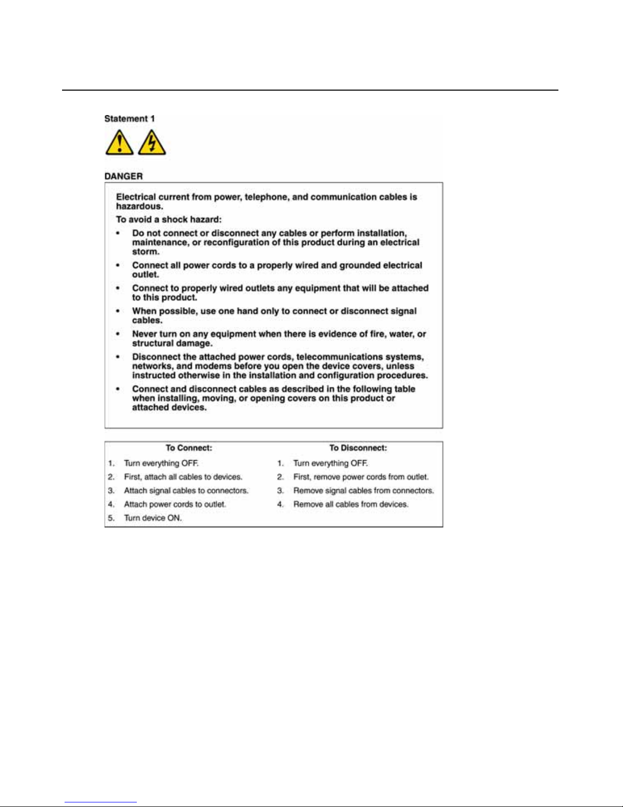
Important:
All caution and danger statements in this documentation begin with a number. This number is used
to cross reference an English caution or danger statement with translated versions of the caution or
danger statement in the IBM Safety Information book.
For example, if a caution statement begins with a number 1, translations for that caution statement
appear in the IBM Safety Information book under statement 1.
Be sure to read all caution and danger statements in this documentation before perfo rm ing the
instructions. Read any additional safety information that comes with the server or optio nal device
before you install the device.
Sound Level Measure
The measured sound level of this appliance is 44.7 dB(A).
Die arbeitsplatzbezogene Geräuschemission des Gerätes beträgt 44,7 dB(A).
Page 7
Page 8

Page 9

vii
Table of Contents
List of Figures .................................................................................................................xi
List of Tables................................................................................................................. xiii
Chapter 1: Product overview .......................................................................................... 1
Features and benefits.........................................................................................................................1
Authorization and authentication ......................................................................................................2
SNMP.................................................................................................................................................2
Virtual media..............................................................................................................................2
Conversion option cables ...........................................................................................................3
OSCAR graphical user interface................................................................................................4
Video...........................................................................................................................................5
Flash upgradability ....................................................................................................................5
Accessing the appliance through network connection................................................................5
Accessing target devices.............................................................................................................5
Example appliance configuration....................................................... ...............................................6
Chapter 2: Installation ..................................................................................................... 7
Required items .................................................. .............................................................. ...................9
Operating System, Browser, and JRE Requirements.........................................................................9
Required adjustments to mouse and cursor settings........................................................................10
Safety precautions............................................................................................................................10
Rack mounting the appliance...........................................................................................................13
General guidelines....................................................................................................................14
Installing the appliance vertically in the side of a rack............................................................14
Installing the appliance horizontally in th e 1-U rack mounting space ....................................15
Connecting hardware to the appliance.....................................................................................16
Verifying Ethernet connections........................................................................................................16
Daisy chaining.................................................................................................................................17
Appliance tiering..............................................................................................................................17
Configuring tiering for the maximum number of targ et devices .....................................................21
Configuration options and default authentication...........................................................................21
Local configuration options......................................................................................................22
TABLE OF CONTENTS
Page 10

viii Global Console Manager Installation and User’s Guide
Remote configuration options...................................................................................................22
Configuring the appliance IP address......................................................................................23
Configuring users accounts and user device access using the Web interface.................................23
Chapter 3: Using the Web Interface ............................................................................. 25
Supported browsers .............. ............................... ............................... ............................... ..............25
Upgrading GCM2 and GCM4 appliances to use the Web interface ...............................................25
Web interface window.................................................................................. ....................................28
Port numbers in Path columns .................................................................................................29
Reboot Required button............................................................................................................29
Video Viewer....................................................................................................................................29
User access rights............................................................................... .............................................30
Connecting to target devices............................................................................................................31
Session sharing options .............................................................. .....................................................31
Viewing and disconnecting session status .......................................................................................32
Overview of viewing and configuring appliance parameters..........................................................33
Configuring network parameters, KVM sessions, virtual media, and authentication.....................34
Configuring users and user access rights........................................................................................39
Enabling Security Lock-out and unlocking user accounts...............................................................41
Configuring SNMP ..........................................................................................................................42
Configuring SNMP traps .................................................................................................................43
Viewing target device information and naming target devices .......................................................45
Viewing CO cable information and setting a CO language ............................................................46
Viewing and configuring cascade devices.......................................................................................47
Viewing software and firmware versions for the appliance ............................................................48
Viewing CO cable version information and administering firmware..............................................48
Using the Tools............................................................................................................... .................51
Rebooting the appliance using the Tools.........................................................................................51
Upgrading the appliance firmware using the Tools ........................................................................52
Upgrading firmware on multiple CO cables using the Tools..........................................................53
Managing appliance configuration files..........................................................................................54
Managing user databases ................................................................................................................56
Chapter 4: Using the OSCAR interface........................................................................ 59
OSCAR interface Main window.......................................................................................................59
Using the OSCAR interface .............................................................................................................61
Page 11

TABLE OF CONTENTS ix
Connecting to a target device..........................................................................................................62
Configuring and starting local virtual media sessions....................................................................62
Configuring the appliance and the OSCAR interface......................................................................64
Assigning target device names......................... ............................... ... ............................... ........65
Configuring ports on cascade devices......................................... ............................... ..............66
Changing the display behavior.................................................................................................68
Selecting the display language .................................................................................................69
Configuring the status flag .......................................................................................................69
Setting the keyboard country code............................................................................................71
Setting appliance security............................................................... ..........................................72
Setting the preemption warning.................................................. .....................................................73
Managing target device tasks using the OSCAR interface..............................................................74
Displaying version information................................................................................................74
Upgrading the CO cable firmware...........................................................................................75
Upgrading the appliance firmware..................................................................................................76
Viewing the switching system configuration ............................................................................76
Viewing and disconnecting user connections...........................................................................76
Resetting the keyboard and mouse ...........................................................................................78
Scanning the switching system.........................................................................................................78
Running switching system diagnostics.............................................................................................80
Broadcasting to target devices ............................ .............................................................. ..............81
Chapter 5: Using the Console Menu ............................................................................ 83
Console Main Menu.........................................................................................................................83
Network Configuration Menu..........................................................................................................84
Security Configuration option ............................................................... ... ............................... ........85
Firmware Management option ........................................................................................................86
Enable Debug Messages option................................................................................................86
Set/Change Password option....................................................................................................8 6
Restore Factory Defaults option............................................ ...................................................8
7
Reset Appliance option............................................... ............................... ...............................87
Enable LDAP Debug Messages option.....................................................................................87
Exit option.................................................................................................................................87
Appendixes..................................................................................................................... 89
Appendix A: Flash upgrades ....................................................................................................89
Page 12

x Global Console Manager Installation and User’s Guide
Appendix B: Virtual media.......................................................................................................91
Appendix C: UTP cabling.........................................................................................................93
Appendix D: Technical specifications......................................................................................95
Appendix E: Getting help and technical assistance .................................................................97
Appendix F: Notices .................................................................................................................99
Index.............................................................................................................................. 107
Page 13

xi
List of Figures
Figure 1.1: GCM2 or GCM4 appliance............................................................................................1
Figure 1.2: Examples of CO cables...................................................................................................3
Figure 1.3: Cat5 cable and a terminator connected to RJ-45 ports on a UCO cable ......................4
Figure 1.4: Example appliance configuration...................................................................................6
Figure 2.1: Basic appliance configuration........................................................................................8
Figure 2.2: Appliance vertical installation............................................... .................................. .....15
Figure 2.3: Appliance horizontal installation .................................................................................15
Figure 2.4: Appliance configuration with a single tiered appliance...............................................18
Figure 2.5: Tiering an earlier-model appliance................................. .................................. ...........19
Figure 3.1: Web interface window with Connections tab selected and Reboot Required button ...28
Figure 3.2: Status window...............................................................................................................33
Figure 3.3: Configure tab with left menu options and Appliance window......................................34
Figure 3.4: Appliance Sessions window....................................... ...................................................35
Figure 3.5: Appliance > Authentication window ............................................................................36
Figure 3.6: Appliance > Authentication window ............................................................................37
Figure 3.7: Users window ...............................................................................................................39
Figure 3.8: Add/Modify User window...................................................... .................................. .....40
Figure 3.9: Users Access window....................................................................................................40
Figure 3.10: SNMP Configuration window.....................................................................................43
Figure 3.11: SNMP Traps Window .................................................................................................44
Figure 3.12: Servers window...........................................................................................................45
Figure 3.13: Modify Server Name window......................................................................................45
Figure 3.14: Servers - COs window ................................................................................................47
Figure 3.15: Modify Cascade Device window.................................................................................47
Figure 3.16: Versions window.........................................................................................................48
Figure 3.17: COs Firmware Version Window.................................................................................49
Figure 3.18: CO Version window....................................................................................................50
Figure 3.19: Tools tab .....................................................................................................................51
Figure 3.20: Upgrade Appliance Firmware window- TFTP server................................................52
Figure 3.21: Upgrade Appliance Firmware window - file system..................................................53
Figure 3.22: Upgrade CO Firmware window.......................................... .......................................54
LIST OF FIGURES
Page 14

xii Global Console Manager Installation and User’s Guide
Figure 3.23: Save Appliance Configuration window ......................................................................55
Figure 3.24: Restore Appliance Configuration window..................................................................56
Figure 3.25: Save Appliance User Data window ............................................................................57
Figure 3.26: Restore Appliance User Data window........................................................................58
Figure 4.1: Example of a Main window..........................................................................................59
Figure 4.2: Setup window................................................................................................................64
Figure 4.3: Names window..............................................................................................................65
Figure 4.4: Name Modify window...................................................................................................66
Figure 4.5: Devices window............................................................................................................67
Figure 4.6: Device Modify window ....................................................... ... ............................... ........67
Figure 4.7: Menu window................................................................................................................68
Figure 4.8: Language window.........................................................................................................69
Figure 4.9: Flag Setup window .......................................................................................................70
Figure 4.10: Set Position window....................................................................................................71
Figure 4.11: Keyboard window.......................................................................................................71
Figure 4.12: Preempt window .........................................................................................................73
Figure 4.13: Commands window.....................................................................................................74
Figure 4.14: Version window ..........................................................................................................75
Figure 4.15: Upgrade window.........................................................................................................76
Figure 4.16: User Status window....................................................................................................77
Figure 4.17: Disconnect window.....................................................................................................77
Figure 4.18: Scan window...............................................................................................................79
Figure 4.19: Diagnostics window....................................................................................................80
Figure 4.20: Broadcast window ......................................................................................................82
Figure 5.1: Console Menu...............................................................................................................83
Figure 5.2: Network Configuration Menu........................................................ ...............................84
Page 15

xiii
List of Tables
Table 1.1: GCM2 and GCM4 appliance model comparison.............................................................6
Table 2.1: Earlier model switches configuration for the (2048(maximum number of target devices.
21
Table 2.2: Local configuration options ...........................................................................................22
Table 2.3: Remote configuration options ........................................................................................22
Table 3.1: User access rights ..........................................................................................................30
Table 3.2: Session sharing definitions.............................................................................................31
Table 3.3: CO cable status symbols.............................................. ...................................................46
Table 4.1: OSCAR interface status symbols ....................................................................................60
Table 4.2: OSCAR interface navigation basics ...............................................................................61
Table 4.3: Setup features to manage routine tasks for the target devices.......................................64
Table 4.4: OSCAR interface status flags ............. ............................................................................69
Table 4.5: Commands to manage routine tasks for the target device .............................................74
Table 4.6: Diagnostic test details....................................................................................................80
Table C.1: UTP wiring standards....................................................................................................93
Table D.1: GCM2 and GCM4 appliance product specifications ....................................................95
LIST OF TABLES
Page 16

xiv Global Console Manager Installation and User’s Guide
Page 17

1
CHAPTER
1
Product overview
The IBM® Global 2x16 Console Manager (GCM2) and the IBM Global 4x16 Console Manager
(GCM4) appliances integrate digital and analog KVM switching technology with advanced cable
management and provide access for up to three or four simultaneous users. Virtual media support is
included. The appliance transmits KVM information between users and target devices attached to
the appliance when the users are either remote or locally connected.
Options for remote management and access include an integrated Web interface and VCS client
software that can be installed on a remote computer. Options for local management and access
include the OSCAR
®
interface available through a monitor, keyboard, and mouse that can be
connected to local user KVM ports on the appliance. Console menu access is also available through
a terminal that can be connected to the serial port.
Each appliance has 16 ports for connecting target devices such as servers and routers. Up to 256
target devices can be managed by daisy-chaining target devices. Additional appliances can be
tiered for support for up to 2048 target devices.
Features and benefits
The appliances are rack mountable KVM switches supporting analog (local) and digital (remote)
connectivity. Video resolutions are supported up to 1280 x 1024 for remote users.
The GCM2 appliance includes support for KVM-over-IP access for two remote users and virtual
media capability for one local user and up to two remote users. The GCM4 appliance includes
support for KVM-over-IP access for four remote users, and virtual media capability for one local
user and up to four remote users.
Figure 1.1: GCM2 or GCM4 appliance
Page 18

2 Global Console Manager Installation and User’s Guide
Users can access connected target devices remotely through the1000BASE-T Ethernet port and
directly through a local user station.
IP access through standard LAN connections supports target device control from anywhere in
the world.
Both appliance models have USB and PS/2 ports for one local user station. USB and PS/2
connectors can be mixed; for example, a USB keyboard and a PS/2 m ouse can be connected.
A terminal or a computer running a terminal emulation program can be connected to the
configuration port for firmware upgrades and other types of configuration.
USB media devices such as CD drives can be connected to any of the four available USB ports for
virtual media support.
Authorization and authentication
Authorization and authentication can be configured to use local databases, or LDAP, or a
combination of both methods, as described below:
• Local authentication is always used, whether it is the primary or backup authenti cation method, and
it cannot be disabled.
• Local databases or LDAP can be used for both authentication and authorizations checking.
• LDAP can be used for authentication only while the local databases are used for authorizations
checking.
SNMP
Administrators can configure Simple Network Management Protocol (SNMP) managers to access
the appliances and can configure traps to be sent to designated SNMP servers.
Virtual media
Virtual media support allows USB media devices, such as CD devices, flash storage devices, and
disk storage devices, to be shared with the target devices. For virtual media to work, the target
device must be directly connected to the appliance with a Virtual Media Conversion Option (VCO)
cable. Virtual media is not supported for target devices that are daisy-chained or that are connected
to tiered appliances.
The media device being shared can be connected either to one of four USB ports on the appliance
or to a USB port on a remote computer. Remotely attached media can be shared with the target
devices using either the Web interface or the Virtual Console Software (VCS) client software
installed on the remote computer.
Using the virtual media capability, users can perform operations on target devices such as installing
or upgrading the operating system; booting from a CD; installing applications; updating the BIOS,
or backing up the system.
Page 19
Chapter 1: Product overview 3
Conversion option cables
A Conversion Option (CO) cable is an intelligent interface that is attached to each target device.
Firmware on the CO cables can be upgraded using the Web interface, the OSCAR interface, the
VCS, or the Console menu.
CO cab le m ode ls support target devices with either PS/2 and USB ports. You must connect one of
the following types of CO cables to each target device:
• IBM 250 mm KVM Conversion Option (KCO) cable - PS/2 and VGA connectors
• IBM 1.5 M KVM Conversion Option (KCO) cable - PS/2 and VGA connectors
• IBM Virtual Media Conversion Option (VCO) cable - USB2 and VGA connectors
NOTE: For virtual media support, the target device must be connected to a VCO cable, and the VCO cable must
be directly connected to the appliance. Virtual media is not supported for daisy-chained target devices or for
target devices connected to tiered appliances.
• IBM USB Conversion Option (UCO) cable - USB and VGA connectors
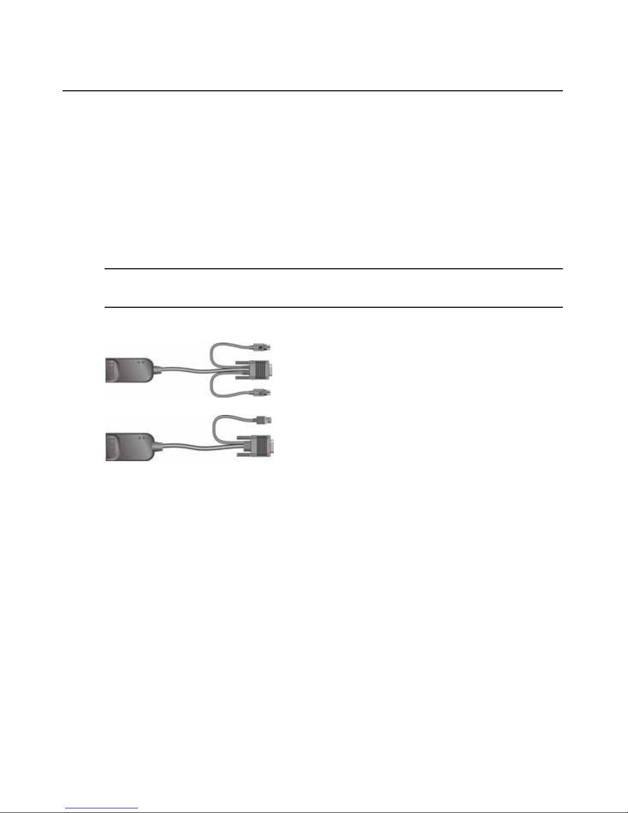
Figure 1.2: Examples of CO cables
Using Cat5 cables dramatically reduces cable clutter while providing optimal digital display
resolution and video settings. The built-in memory of each CO cable simplifies configuration by
storing unique identification codes and optional names that can be configured for each attached
target device.
The intelligence integrated into the CO cable enhances security and prevents unauthorized access
to a target device through cable manipulation. Each CO cable receives power directly from the target device.
Keep Alive functionality on the CO cables emulates a keyboard to prevent server lock-up even if
the appliance is not turned on or if the connection between the CO cable and the switch is
interrupted.
Each KCO and UCO cable has two RJ-45 ports for connecting Cat5 cables. Each VCO has one RJ45 port. The RJ-45 ports are used in the following ways.
• A Cat5 cable must be connected to an RJ-45 port on the CO cable of a target device and to an ARI
port on a standalone or tiered appliance.
UCO or VCO cable
KCO cable
Page 20

4 Global Console Manager Installation and User’s Guide
• When target devices are daisy chained from a single ARI port, a Cat5 cable must be connected to the
second RJ-45 port on a KCO or UCO that is connected to a target device. The other end of the Cat5
cable must then be connected to the first RJ-45 port on a KCO or UCO cable that is connected to the
next target device in the chain.
• When only one target device is connected to a port with a KCO or UCO cable or when the target
device is the last in a daisy chain, a terminator must be connected to the second RJ-45 port on the
connected KCO or UCO cable.
Figure 1.3: Cat5 cable and a terminator connected to RJ-45 ports on a UCO cable
OSCAR graphical user interface
Users at a local user station can use the OSCAR interface, which provides menus to configure the
switching system and select target devices. You can list target devices by unique name, eID
(electronic ID), or port number. See Chapter 3 for details on how to use the OSCAR interface.
Security
Administrators can configure the OSCAR interface to restrict access to the switching system by
configuring a password and the screen saver. After an administrator-defined period of inactivity,
the screen saver engages and access is not allowed until the correct password is entered.
Operation modes
The OSCAR user interface allows administrators to configure the broadcast, scan, switch, and
share operation modes for the target devices.
Cat5 cable
Terminator
Page 21

Chapter 1: Product overview 5
Video
The appliance provides optimal resolution for analog VGA, SVGA, and XGA video. Resolutions
of up to 1280 x 1024 can be achieved depending upon the length of cable that is separating the
appliance and target devices.
Flash upgradability
The appliance firmware can be upgraded to a more-current version using the Web interface, the
OSCAR interface, the VCS, or the Console menu.
See Appendix A for more information about how to upgrade the firmware.
Accessing the appliance through network connection
The appliance uses TCP/IP for communication over Ethernet. The network port supports up to
1000BASE-T Ethernet. 10BASE-T and switched 100BASE-T Ethernet can be used. The network
port gives administrators and users digital access to the switching system.
Accessing target devices
When a user accesses OSCAR, the Web interface, or the VCS, a list appears with all target devices
the user have permission to view and manage. When a target device is selected from the list, a
KVM session is created with video of the selected target device displaying in a Video Viewer
window.
NOTE: The Video Viewer requires JRE 5.0 update 11 to be installed on the computer.
Page 22

6 Global Console Manager Installation and User’s Guide
Example appliance configuration
Figure 1.4: Example appliance configuration
Table 1.1: GCM2 and GCM4 appliance model comparison
Model Ports Remote
users
Local
users
Local virtual media
sessions
Remote virtual media
sessions
GCM2 16 2 1 1 2
GCM4 16 4 1 1 4
Remote user
GCM2 or GCM4 appliance
Ethernet
Remote user
Rack of
target devices
Local user
Virtual media
device
Page 23

7
CHAPTER
2
Installation
The following tasks to set up and configure the appliance are described in this chapter:
1. Unpack the appliance and verify that all components are present and in good condition. See
“Required items” on page 9.
2. Make the needed mouse setting adjustments on each target device to be connected. See
“Required adjustments to mouse and cursor settings” on page 10.
3. Read and follow the “Safety precautions” on page 10.
4. Rack mount the appliance. See “Rack mounting the appliance” on page 13.
5. Make all hardware connections between the power source, appliance, local user station, target
devices, and the Ethernet network. See the following sections:
• “Connecting hardware to the appliance” on page 16
• “Daisy chaining” on page 17
• “Appliance tiering” on page 17
See also the Quick Installation Guide.
6. After turning on the power, verify that all connections are working. See “Verifying Ethernet
connections” on page 16.
7. Configure access to the appliance. See “Configuration options and default authentication” on
page 21.
Page 24
8 Global Console Manager Installation and User’s Guide
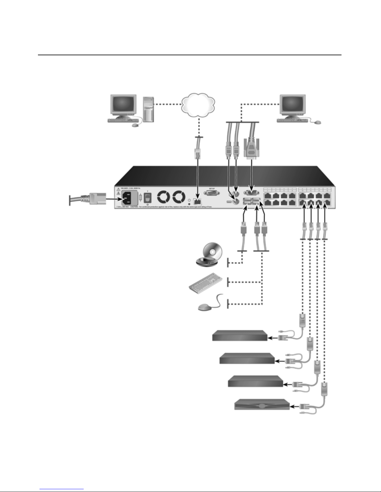
The following diagram illustrates one possible configuration for the appliance.
Figure 2.1: Basic appliance configuration
Digital user
Power
Network
cord
Local user
ARI ports
1-16
Cat5
cable
* To allow a virtual media session with a target
device, the target device must have a VCO cable
attached. Virtual media sessions are not
supported on chained target devices or on
target devices when they are connected to
tiered appliances or switches that do not
support virtual media.
Target devices 1-16
Virtual media device*
Peripherals
VCO, KCO, or UCO cable
Page 25

Chapter 2: Installation 9
Required items
Before you install the appliance, make sure that you have all the required items. The following
items come with the appliance:
• Power cord
• Rack-mounting brackets
• Documentation CD
• Virtual Console Software Installation CD
• Quick Installation Guide
• 1-U filler panel
• 16 terminators
The following additional items are needed:
• A Phillips screwdriver
• For each target device to be connected, one IBM Conversion Option (KCO, UCO, or VCO)
and one Cat5 cable
• For each switch to be tiered, one Cat5 cable.
• For each switch to be tiered with a KCO, one IBM KVM Conversion Option (KCO)
Operating System, Browser, and JRE Requirements
Target devices must be running one of the following operating systems:
• Microsoft
®
Windows® 2000 Server and Advanced Server
• Microsoft Windows XP Professional and Standard 32-bit
• Microsoft Windows Server 2003 Web, Standard, and Enterprise 32-bit
• Microsoft Windows Server 2003 Enterprise IA64, Standard and Enterprise EM64T
• Microsoft Windows Vista St andard and Enterprise 32-bit
• Microsoft Windows Vista Standard and Enterprise EM64T
• Red Hat® Enterprise Linux® 3.0. 4.0, and 5.0, IA32 and EM64T, WS, ES, and AS
Client computers running the VCS must be running one of the following operating system versions:
• Microsoft Windows 2003 Server with Service Pack 1 Web, Standard, and Enterprise
• Microsoft Windows XP Professional with Service Pack 2
• Microsoft Windows Vista Business
• Microsoft Windows 2000 Professional with Service Pack 4
• Red Hat Enterprise Linux 3.0. 4.0, and 5.0 WS, ES, and AS
• SUSE Linux Enterprise Server 9 and Server 10
Page 26

10 Global Console Manager Installation and User’s Guide
Computers used to access the Web interface and client computers running the VCS must have one
of the following browsers installed:
• Internet Explorer 7.0 or later
• Netscape 7.0 or later
• Firefox 2.0 or later
Computers used to access the Web interface and client computers running the VCS must have Java
Runtime Environment JRE 5.0 update 11 installed. (The Video Viewer does not work witho ut th e
correct version of the JRE.)
Required adjustments to mouse and cursor settings
To ensure that the local mouse movement and remote cursor (pointer) display are in sync, the
mouse settings must be changed on each remote computer used for accessing the switching system
and on each target device.
In the mouse properties, ensure that cursor acceleration (sometimes called the pointer speed) is set
to Slow or None and that “snap to default” is not enabled.
Special cursors should not be used. Also make sure that cursor visibility options, such as pointer
trails,
Ctrl key cursor location animations, cursor shadowing and cursor hiding are turned off.
NOTE: To work around cursor synchronization problems, you can use the Tools - Single Cursor Mode command
available in the Viewer window to manually toggle control between the cursor on the target device being viewed
and the cursor on the computer from which you are accessing the switching system. The Viewer is described in
the VCS Installation and User’s Guide.
Safety precautions
Observe the following guidelines to safely operate the equipment.
Page 27
Chapter 2: Installation 11
Page 28
12 Global Console Manager Installation and User’s Guide
General
• Observe and follow service markings.
• Do not service any appliance except as explained in the appliance documentation.
• Opening or removing covers that are marked with the triangular symbol with a lightn ing bolt
might expose you to electrical shock. Components inside these compartments must be only
serviced by a trained service technician.
• The appliance contains no serviceable components. Do not attempt to open the appliance.
• If any of the following conditions occur, disconnect the appliance from the electrical outlet and
replace the part or contact the trained service provider:
• The power cable, extension cable, or connector is damaged.
• An object has fallen into the product.
• The appliance has been exposed to water.
• The appliance has been dropped or damaged.
• The appliance does not operate properly when you fo llo w the operating instructions.
Page 29

Chapter 2: Installation 13
• Keep the appliance away from radiators and heat sources. Also, do not block
cooling vents.
• Do not spill food or liquids on the appliance components, and never operate the appliance in a
wet environment. If the appliance gets wet, see the applicable section in the troubleshooting
guide or contact the trained service provider.
• Use the appliance only with approved equipment.
• Allow the appliance to cool before removing covers or touching internal components.
• Operate the appliance only from the type of external power source that is indicated on the elec-
trical ratings label. If you are not sure of the type of power source that is required, consult the
service provider or local power company.
• Be sure that the monitor and attached devices are electrically rated to operate with the power
that is available in the current location.
• Use only power cables that are provided with the appliance.
• To help prevent electric shock, connect the appliance and peripheral power cables into properly
grounded electrical outlets. These cables are equipped with three-prong connectors to help
ensure proper grounding. Do not use adapter connectors or remove the grounding prong from
a cable.
• Observe extension cable and power strip ratings. Make sure that the total ampere rating of all
products that are connected to the power strip does not exceed 80 percent of the ampere ratings
limit for the power strip.
• To help protect the appliance from sudden, transient increases and decreases in electrical
power, use a surge suppressor, line conditioner, or uninterruptible power supply.
• Carefully position appliance cables and power cables. Route cables so that they cannot be
stepped on or tripped over. Be sure that nothing rests on any cables.
• Do not modify power cables or connectors. Consult a licensed electrician or the power com-
pany for site modifications. Always follow the local and national wiring rules.
Rack mounting the appliance
Before installing the appliance and other components in the rack (if not already installed), stabilize
the rack in a permanent location. Install the equipment starting at the bottom of the rack, and then
work to the top. Avoid uneven loading or overloading of racks.
Page 30

14 Global Console Manager Installation and User’s Guide
General guidelines
• Refer to the rack installation documentation that accompanied the rack for specific caution
statements and procedures.
• Elevated ambient temperature: In a closed rack assembly, the operation temperature of the rack
environment can be greater than room ambient. Use care not to exceed the rated maximum
ambient temperature of the unit.
• Reduced air flow: Carefully install the equipment in a rack so that an adequate amount of air-
flow is maintained for safe operation of the equipment.
• Mechanical loading: Avoid a potentially hazardous condition caused by uneven mechanical loading
by carefully mounting the equipment in the r ack.
• Circuit overloading: Consider the connection of the equipment to the supply circuit and the
effect that overloading of circuits might have on overcurrent protection and supply wiring.
Observe equipment nameplate ratings for maximum current.
• Reliable earthing: Maintain reliable earthing of rack-moun ted equipment. Pay particular atten-
tion to supply connections other than direct connections to the branch circuit (for example, use
of power strips).
Installing the appliance vertically in the side of a rack
To install the appliance vertically, complete the following steps:
1. Remove the screws that are on each side of the appliance.
2. Line up the small holes of the L-shaped brackets with the screw holes in the appliance.
3. With a Phillips screwdriver, fasten the mounting brackets to the appliance using two 8/32-inch
x 1/2-inch pan-head screws on each side.
4. Mount the appliance assembly to the rack by matching the long slots on each bracket to a set of
holes on the rack. Next, insert a combination hex-head screw through the slots in the bracket
and the holes in the rack. Cap the screw with a hex serrated flange nut and tighten.
The mounting holes on the upper and lower side braces in a rack side compartment must be
between 50.8-cm (20.0-in.) and 57.3-cm (22.6-in.) apart. If the rack has movable side braces,
refer to the rack documentation for information about relocating side braces if they are not
already spaced for this installation.
Page 31

Chapter 2: Installation 15
Figure 2.2: Appliance vertical installation
Installing the appliance horizontally in the 1-U rack mounting space
NOTE: The filler panel must be placed in front of the rack when the appliance is mounted in the horizontal
1-U orientation.
To install the appliance horizontally, complete the following steps:
1. Remove the screws on each side of the appliance.
2. Line up the holes in the long side of each mounting bracket.
3. With a Phillips screwdriver, fasten the mounting brackets to the appliance using two 8/32-inch
x 1/2-inch pan-head screws on each side.
4. Attach four cage nuts or clip nuts to the rack mounting flange of the rack so that the nut is
positioned on the inside of the rack.
5. Mount the appliance assembly to the rack by matching the holes in the short side of each
mounting bracket to a set of matching holes on the rack. Insert the combination hex-head
screws through the slots in the mounting bracket and the holes in the mounting rail, then into
the cage nuts or clip nuts.
Figure 2.3: Appliance horizontal installation
Page 32

16 Global Console Manager Installation and User’s Guide
Connecting hardware to the appliance
To connect and turn on the appliance, complete the following steps:
1. Turn off the target devices that are part of the switching system. Connect one end of the
supplied power cord to the back of the appliance and connect the other end of the cord to an ac
power source.
2. Connect a VGA monitor and keyboard and mouse cables into the labeled ports.
PS/2 or USB keyboard and mouse connectors can be mixed. You must install both a keyboard
and a mouse or the keyboard does not initialize correctly. Do not connect a DVI or EGA
monitor. Label the cables for easy identification.
3. Connect target devices.
a. Locate the appropriate model of CO (KCO, UCO, or VCO) cable for the target device.
b. Connect the CO cable to the target device.
c. Connect one end of a Cat5 patch cable (4-pair, up to 10 meters) into an RJ-45 port on the
CO cable.
d. Connect the other end of the Cat5 cable from the CO into an ARI port on the back of the
target device. Repeat steps a through d for all target devices to be directly connected.
e. Connect a terminator to the second RJ-45 port on each KCO or UCO, unless you are
daisy-chaining another target device to the sam e port . If you are chaining multiple target
devices, follow the procedure under “Daisy chaining” on page 17.
4. Connect a Cat5 patch cable from the Ethernet network into the LAN port on the back of the
appliance.
5. If you plan to use the Console menu interface for configuration or firmware upgrades, connect
a terminal or a computer running terminal emulation software to the configuration port on the
back panel of the appliance using a straight through serial cable. Ensure terminal settings are
9600 bits per second (bps), 8 bits, 1 stop bit, no parity, and no flow control.
6. To enable local virtual media, connect a USB media device to a USB port on the appliance.
7. Turn on each target device and then turn on the appliance.
8. After approximately one minute, the appliance completes initialization and opens the OSCAR
graphical user interface Free tag on the monitor of the local user station.
9. Configure access to the appliance. See “Configuration options and default authentication” on
page 21.
Verifying Ethernet connections
Check the LEDs next to the Ethernet port after the system is turned on. The green LED on the right
is the Link indicator. It lights when a valid connection to the network is established, and it flashes
when there is activity on the port. The amber/green LED on the left indicates that the speed of the
Ethernet connection is either 100 Mbps (amber) or 1000 Mbps (green).
Page 33

Chapter 2: Installation 17
Daisy chaining
You can daisy chain up to 16 target devices from each ARI port allowing up to 256 target devices
to be managed by a single GCM2 or GCM4 appliance.
To daisy chain target devices, complete the following steps:
1. Connect one end of a Cat5 cable to the second RJ-45 port on a KCO or UCO cable that is
connected to a target device.
2. Connect the other end of this cable to the first RJ-45 port of the KCO or UCO cable for a target
device being chained.
3. Repeat steps 1 and 2 for all target devices being chained together.
4. When you reach the end of the chain, attach a terminator to the second RJ-45 port on the last
KCO or UCO cable in the chain.
Appliance tiering
GCM2 and GCM4 appliances can be tiered to integrate up to 256 target devices as part of the same
switching system. Compatible earlier-model KVM switches can be tiered to enable management of
up to 2048 target devices from a single GCM2 or GCM4 appliance.
The GCM2 or GCM4 appliance automatically discovers cascade devices (either tiered appliances
or tiered legacy switches), but an administrator must specify the number of ports on the cascade
device using either the Web interface, the VCS, or the OSCAR interface.
See “Configuration options and default authentication” on page 21 for more information about
these configuration options. See “To configure a cascade device name and the number of channels,
complete the following steps:” on page 48 for how to specify the number of ports using the Web
interface.
Page 34

18 Global Console Manager Installation and User’s Guide
Figure 2.4: Appliance configuration with a single tiered appliance
Local user
GCM2 appliance (main)
ARI ports
Primary target devices
Tiered (secondary)
LCM2 appliance
Secondary target devices
ACI port
Page 35

Chapter 2: Installation 19
Each ARI port on the main GCM2 or GCM4 appliance can be connected with a Cat5 cable to
another compatible switch in either of the two following ways:
• By connecting to the ACI port of another GCM2 or GCM4 appliance or an earlier-model
switch
• By connecting to a KCO that is connected to the local user ports on an earlier-model switch
Figure 2.5: Tiering an earlier-model appliance
All target devices that are connected to tiered appliances are listed in the main appliance target
device list.
GCM2 or GCM4 appliance
KCO cable
IBM NetBay 2x8
Console Switch
IBM NetBAY 1x4
Console Switch
Target device 2
Local user
Target device 1
Cat5 cable
KCO cable
Page 36

20 Global Console Manager Installation and User’s Guide
The following earlier-model switches are compatible with the GCM2 and GCM4 appliances:
•IBM NetBAY
TM
1x4 Console Switch
• IBM NetBAY 2x8 Console Switch
• IBM NetBAY ACT Remote Console Manager
• IBM NetBAY ACT Local Console Manager
• IBM 1x8 Console Switch
• IBM 2x16 Console Switch
When tiering earlier-model switches, make sure a GCM2 or GCM4 appliance is the primary (or
main) appliance at the top level of the tier. Up to two levels of tiering are supported with the listed
earlier-model appliances.
To tier multiple GCM2 or GCM4 appliances, complete the following steps:
1. Mount the secondary GCM2 or GCM4 appliance in the same rack with the main GCM2 or
GCM4 appliance.
2. Connect all target devices.
3. Attach one end of a Cat5 cable to the ACI port on the tiered appliance.
4. Attach the other end of the Cat5 cable to one of the ARI ports on the primary appliance.
5. Specify the number of ports on the tiered appliance using the Web interface, the VCS, or the
OSCAR interface.
To tier earlier-model appliances to a GCM2 or GCM4 appliance, complete the following
steps:
1. Mount the earlier-model appliances in the same rack with the main GCM2 or GCM4 appliance
according to the instructions that are included with the appliances.
2. If using a CO cable to connect a tiered appliance, complete the following steps:
a. Attach the keyboard, monitor, and mouse connectors of a CO cable to the local user ports
on the tiered appliance.
b. Attach one end of a Cat5 cable to the end of the CO cable.
c. If using a CO cable to connect a tiered appliance, attach a terminator to the second RJ-45
port on the CO cable that is connected to the last appliance in the tier.
3. If using a Cat 5 cable to connect the tiered appliance, complete the following steps:
a. Connect a Cat5 cable directly to the RJ-45 connector (ACI port) on the tiered appliance.
b. Connect the other end of the Cat5 cable to an ARI port on the back of the appliance.
4. Turn off and turn on the target devices that are connected to the tiered appliance according to
the instructions that are included with that device.
5. If using a CO cable, turn off and turn on the tiered appliance to enable its local port to
recognize the CO cable.
Page 37

Chapter 2: Installation 21
6. Specify the number of ports on the tiered appliance using the Web interface, the VCS, or the
OSCAR interface.
7. Repeat steps 2 to 6 for all appliances.
Configuring tiering for the maximum number of target devices
Tiering the maximum number of 2048 target devices requires you to connect 16 IBM Local 2x8
Console Manager (LCM2) appliances to the ARI ports of one GCM2 or GCM4 appliance.
From the eight ARI ports on the LCM2 secondary appliances, you can either tier eight IBM 2x16
Console Switch appliances or you can daisy-chain 16 target devices.
To configure the maximum number of 2048 target devices, complete the following steps:
1. Use a Cat5 cable to connect each of the 16 ARI ports on a single GCM2 or GCM4 appliance to
the ACI port on each of the 16 LCM2 appliances.
2. Tier additional appliances or chain additional target devices to the ARI ports on each of the
LCM2 appliance.
• To tier another level of appliances: Use a Cat5 cable to connect each of the eight ARI ports
on each tiered LCM2 appliance to the ACI port on each of the eight 2x16 Console Switch
appliances
• To daisy-chain target devices from the secondary tier: Connect a chain of 16 target devices
to each of the eight ARI ports on each tiered LCM2 appliance.
Configuration options and default authentication
This section compares the local and remote configuration options and the default authentication
needed for accessing each option. The appliance has a default user account configured with
username Admin and no password.
NOTE: For security, assign a password to the Admin account immediately the first time you access any of the
configuration options.
Configure user access to the target devices in the switching system by using one or a combination
of the local and remote options.
Table 2.1: Earlier model switches configuration for the (2048(maximum number of target devices
Primary Secondary Tertiary
GCM2 or GCM4 Up to 16 LCM2 2x8 appliances Eight 2x16 console switch appliances (each
with 16 target devices connected)
-or16 target devices daisy-chained from each of
the ARI ports
Page 38

22 Global Console Manager Installation and User’s Guide
Local configuration options
By default, the OSCAR interface and the Console menu are available to any user who is able to
access the local user station or a terminal connected to the serial configuration port.
Remote configuration options
Remote configuration options are available on a computer that has network access to the appliance
by using either the VCS client software or the integrated Web interface.
Table 2.2: Local configuration options
Option How accessed Default authentication
How authentication is
configured.
OSCAR interface
See Chapter 4.
Keyboard, monitor, mouse
connected to appliance
None. Press Print
Screen to access.
Configure screen saver, assign a
password to Admin, create other
accounts and passwords.
Console menu
See Chapter 5.
Terminal or computer with
terminal emulation program
that is connected to the
configuration port on the
appliance
None. Connect the
terminal. Press Enter
until Console Main
Menu appears.
Set a console password.
Table 2.3: Remote configuration options
Option How accessed Default authentication
How authentication is
configured.
Web interface
See Chapter 3.
After appliance IP address is
configured, enter IP address in
a supported browser on a
computer with network access
to the appliance.
Access to the Web
interface requires login
with a user name and
password. Default User
name: Admin; Password:
<none>.
Access to target devices
requires login also.
Assign a password to
Admin, create other
accounts and assign them
passwords.
VCS
See the VCS
Installation and
User’s Guide
Install and start the VCS client
on a supported computer.
The VCS Explorer does
not require a login. Access
to target devices requires
login with a user name
and password.
Use the VCS to first
discover and then
configure the appliance.
Create users and specify
their passwords and target
device access.
Page 39

Chapter 2: Installation 23
Configuring the appliance IP address
Users enter the IP address for the appliance in a browser to access the Web interface.
Administrators can initially configure the IP address using either the Console menu, the OSCAR
interface or the VCS. Both DHCP and static IP addressing are supported. The use of a static IP
address is recommended.
To configure the IP address, restrict access, and assign target device names using the
OSCAR interface, complete the following steps:
1. From the keyboard of the local user station, press Print Screen. The OSCAR interface
window displays the Main window with a list of the connected target devices by port number.
2. Click Setup > Names. The Names window appears.
3. Enter a name for each target device.
4. Click OK to return to the Main window.
5. Click Setup > Security.
6. Double-click the New field and type a password for the Admin.
7. Select the Enable Screen Saver checkbox.
8. In the Inactivity Time field, type a number of seconds.
9. Click OK to return to the Main window.
10. Click Setup > Network.
11. Configure the network speed, transmission mode, and the IP address.
12. Click OK to save.
13. Press Esc to return to the Main window.
14. Press Esc to exit the OSCAR interface.
Configuring users accounts and user device access using the
Web interfac e
To configure user accounts and specify target device access using the Web interface,
complete the following steps:
1. Enter the appliance IP address in a browser.
2. Log into the Web interface.
3. Click the Configure tab.
4. From the left menu, click Users.
5. Click the Add User button.
6. Specify the username and password.
7. Click Set User Access Rights.
8. Select the checkbox next to one or more device names.
Page 40

24 Global Console Manager Installation and User’s Guide
9. Click Save to enable the user’s access to devices.
10. Repeat steps 5 to 9 until all users are configured.
11. Click Logout to exit from the Web interface.
Page 41

25
CHAPTER
3
Using the Web Interface
The integrated Web interface is accessed from a computer that has network access to the appliance.
The user enters the IP address configured for the appliance in a supported browser and logs into the
Web interface when prompted.
Administrators can use the Web interface for viewing all system status and for system
configuration. Users can use the Web interface to launch the Video Viewer and establish KVM and
virtual media sessions with target devices, and they can view certain system configuration
information.
Supported browsers
The following browsers are supported for accessing the Web interface:
• Microsoft Internet Explorer version 6.0 or later
• Firefox version 2.0 or later
• Netscape version 7.0 or later
Upgrading GCM2 and GCM4 appliances to use the Web interface
You need to use the latest version of the VCS to upgrade GCM2 and GCM4 appliances to the
firmware version that supports the Web interface. Perform the following tasks, which are described
in this section:
• Download and install the latest version of the VCS software on a computer.
• Download the appliance firmware either onto a TFTP server or onto the VCS client computer.
• Upgrade the firmware on each GCM2 and GCM4 appliance to a version that supports the Web
interface, using the firmware upgrade tool in the VCS Appliance Management Panel (AMP).
• Use the VCS Migration Wizard and the Resync Wizard to migrate and resync upgraded appliances.
NOTE: After a GCM2 or GCM4 appliance is upgraded and migrated, the appliance and its target devices can be
managed using either the Web interface or the VCS. For more details about using the VCS, see the VCS
Installation and User’s Guide.
Page 42

26 GCM2 and GCM4 Installation and User’s Guide
To start the VCS and access the AMP for an appliance, complete the following steps:
1. Download and install the latest version of the VCS on a client computer.
2. Start the VCS. (The examples assume the software is installed in the default locations.)
• In Microsoft Windows operating systems, select Start > Programs > IBM Virtual Con-
sole Software.
• In the Linux operating system, go to /usr/lib/IBM_Virtual_Console_Software/ and
enter:
./IBM_Virtual_Console_Software.
3. In the VCS Explorer window, click Appliances.
4. Select the appliance to upgrade from the list. The appliance login window appears if you are
not currently logged in.
5. Log in if needed. The AMP opens.
To upgrade appliance firmware, complete the following steps:
1. Download a version of the firmware that includes support for the Web interface from: http://
www.ibm.com/support/ either onto the computer that is running the VCS or onto a TFTP
server.
2. In the VCS Appliances window, select the appliance, and click the Tools tab.
3. Save the appliance configuration and appliance user database files. "Managing appliance
configuration files" on page 54 and "Managing user databases" on page 56.
4. Upgrade the appliance firmware. See "To upgrade appliance firmware, complete the following
steps:" on page 26.
NOTE: Do not exit the AMP until the upgrade and reboot are complete to allow the migration flag for the
appliance to be set in the database.
5. Perform the steps in the upgrade procedure until all appliances are upgraded.
6. Click OK to exit the AMP.
7. Migrate and resync the upgraded appliance(s).
To migrate upgraded appliances, complete the following steps.
1. In the VCS Explorer, click Tools > Migrate. The Migration Wizard appears.
2. Click Next. Upgraded appliances appear in the Available Appliances list.
3. If upgraded appliances do not appear in the list, complete the following steps:
a. Click Cancel to exit the Migration Wizard.
b. Click Cancel to exit the Tools tab and exit the AMP.
c. Select the appliance and bring up the AMP again so it can detect the upgraded
appliance(s).
d. Click Tools > Migrate.
e. Click Next.
Page 43

Chapter 3: Using the Web Interface 27
4. Select each appliance to be migrated and click > to move the appliance from the Available
Appliances list to the Appliances to migrate list.
5. To use the local database appliance information, select the Use Local Database Information
check box.
6. Click Next. The Completing the Migration Wizard window appears.
7. Click Finish to exit the Wizard.
To resync migrated appliances, complete the following steps:
1. In the VCS Explorer, right click the name of the appliance. The Resync button appears.
2. Click the Resync button. The Resync Appliance Wizard appears.
3. Click Next. A page with a warning and two check box options appears.
4. Read the warning, select the check box options as desired, and click Next. The Completing the
Resync Appliance Wizard appears.
5. Click Finish to exit.
To remove support for the Web interface on an appliance, remove the following steps:
1. In the Web interface, select the appliance.
2. Use the Firmware upgrade feature of the Web interface to install an earlier version of the
firmware that does not support the Web interface. See "Viewing software and firmware
versions for the appliance" on page 48.
3. In the VCS Explorer window, click Units, right click the name of the appliance, click Delete in
the pop-up menu, and click Yes to confirm.
4. In the VCS Explorer window, select Units > New Appliance. Follow the steps in the New
Appliance Wizard to add the appliance back again.
Page 44

28 GCM2 and GCM4 Installation and User’s Guide
Web interface window
This section gives an overview of the tabs, defines the Path numbering conventions, and the Reboot
Required button.
Figure 3.1: Web interface window with Connections tab selected and Reboot Required button
The Web interface has four tabs: Connections, Configure, Status, and Tools.
Page 45

Chapter 3: Using the Web Interface 29
• Connections - Connect to target devices. See "Connecting to target devices" on page 31.
• Status - View session status and disconnect sessions. See "Viewing and disconnecting session
status" on page 32.
• Configure - Configure the appliance network parameters, KVM session parameters (timeouts,
encryption, sharing options), user accounts and user target device access, SNMP, servers, and
CO cables. See "Overview of viewing and configuring appliance parameters" on page 33.
• Tools - Reboot the appliance, upgrade firmware on the appliance and CO cables, save and
restore appliance configuration files, save and restore appliance and user databases. See "Using
the Tools" on page 51.
Port numbers in Path columns
When a target device is connected directly to the main appliance, the port number on the appliance
is shown in the Path column. For example, in Figure 3.1 the Path column for the server named
ACER XPPRO shows the server is connected to port 08.
A GCM2 or GCM4 appliance or a legacy switch that is tiered from the main appliance is referred to
as a cascade device. When a target device is connected to a cascade device, the port number on the
main appliance is shown on the left followed a dash, which is followed by CH and then followed by
the port (channel) number on the cascade device where the targ et device is connected.
As shown in Figure 3.1, 01- CH 02 displays in the Port column for a server named 180ES PORT2,
which is connected to port 02 of a cascade device that is connected to port 01 of the primary
appliance.
Reboot Required button
When an administrator makes any changes that require a reboot, the Reboot Required button
displays at the lower right of the window as shown in Figure 3.1. At any time or after completing
all configuration changes, an administrator can reboot the system by clicking the Reboot Re quired
button. Changes do not go into effect until a reboot is performed. See also "Rebooting the appliance
using the Tools" on page 51 for how an administrator can reboot using the Tools.
Video Viewer
When a user selects a target device from the list on the Connections tab, the Video Viewer window
appears. A logged-in user has access to the target device desktop.
The Java Runtime Environment (JRE 1.5.0_11) must be installed on the remote computer for the
Video Viewer to work.
To ensure that the local mouse movement and remote cursor (pointer) display are in sync, the
mouse settings must be changed on each remote computer used for accessing the switching system
and on each target device. See "Required adjustments to mouse and cursor settings" on page 10.
NOTE: To work around cursor synchronization problems, you can use the Tools - Single Cursor Mode command
available in the Viewer window to manually toggle control between the cursor on the target device being viewed
Page 46

30 GCM2 and GCM4 Installation and User’s Guide
and the cursor on the computer from which you are accessing the switching system. The Viewer is described in
the VCS Installation and User’s Guide.
User access rights
Three access rights are defined: User, User Administrator, and Appliance Administrator. The
access rights (or levels) assigned to a user account affect which target devices the user can access,
and whether the user can preempt existing KVM sessions or view existing KVM sessions in stealth
mode. The access rights also affect what types of configuration a user can perform on the
appliance.
To access the Web interface, complete the following steps:
1. Enter the appliance IP address in a browser. The login window appears.
2. Type the username and password and click OK. The Web interface window appears with the
Connections tab selected.
To exit the Web interface, perform the following step:
NOTE: If an administrator has specified an Inactivity Timeout, a user with any type of access is logged out
automatically if the specified number of minutes elapses without activity
To log out manually, click Logout in the upper right of Web interface.
Table 3.1: User access rights
Allowed Actions User
User
Administrator
Appliance
Administrator
If Preempt mode is enabled, preempt other
user sessions. If Stealth mode is enabled, view
primary user sessions in stealth mode.
Note: Preemptions only apply to remote users.
No Equal and lesser All
Configure network and global parameters
(security mode, timeouts, SNMP).
No No Yes
Reboot and upgrade firmware. No No Yes
Configure user accounts. No Yes Yes
Monitor target device status. No Yes Yes
Access target devices. Assigned by Admin Yes Yes
Page 47

Chapter 3: Using the Web Interface 31
Connecting to target devices
When the Connections tab is clicked, the window displays a list of target devices that are directly
connected and daisy chained to the GCM2 or GCM4 appliance and that are connected or daisy
chained to any cascade device. A user creates a KVM session by clicking on the name of a target
device.
Session sharing options
Session sharing can be configured by Admin and other users with Appliance Administrator or User
Administrator rights. The first user with a KVM session with a target device is called the primary
user. If another (secondary) user attempts to start a KVM session the same target device, options
for the secondary user depend on the following two conditions:
• The access rights of the users
• Whether an administrator has configured global connection sharing
Automatic Sharing, Exclusive Connections, and Stealth Connections all are configurable
options that require Sharing to be enabled.
For more information about access rights and session types, see "Configuring users and user access
rights" on page 39.
To connect to target devices using the Web interface, complete the following steps:
1. Log into the W eb interface as any user configur ed for access to one or more tar get devices. The
Web interface appears with the Connections tab active.
2. Click the name of a target device. A Video Session Viewer information dialog briefly appears
followed by a status dialog.
Table 3.2: Session sharing definitions
Term Definition
Automatic Sharing
Secondary users can share a KVM session without first requesting permission from
primary users.
Exclusive Connections
Primary users can designate a KVM session as an exclusive connection that cannot
be shared.
Stealth Connections
Stealth connections allow undetected viewing of KVM sessions. Secondary users
with Appliance Administrator rights can create stealth connections to any KVM
session. Secondary users with User Administrator rights can create stealth
connections when their access rights are the same as or higher than the rights of
the primary user. Stealth permissions follow preemption permissions.
Preempt mode
Secondary users with Appliance Administrator rights can preempt sessions.
Secondary users with User Administrator rights can preempt sessions only when
their access rights are the same as or higher than the rights of the primary user.
Page 48

32 GCM2 and GCM4 Installation and User’s Guide
3. If another user does not have an active KVM session with the target device, the Video Viewer
window appears.
• If another user has an active KVM session with the target device, and sharing is not
enabled, or if the number of port sessions has been exceeded, a message window displays
and you are denied access to the target device.
• If sharing is enabled, you can have several options depending on your access rights and on
whether session sharing, session preemption, or stealth connections are enabled.
• If you have Appliance Administrator rights, you can share any session, preempt the ses-
sion, or observe the session in stealth mode.
• If you have User Administrator rights, you can share the session, preempt the session,
or observe the session in stealth mode only if your rights are the same as or higher
than the primary user.
• If an administrator has enabled exclusive connections, and a primary user has set
Exclusive Mode for the session, you cannot share the session unless you have Appliance Administrator rights.
4. If an administrator has enabled exclusive sessions, you can click the Exclusive Mode option in
the Video toolbar Tools menu. The Exclusive Mode status symbol appears in the toolbar.
5. To start a Virtual Media session with a device, click Tools > Virtual Media on the Video
Viewer tool bar. The Virtual Media Session window appears showing the physical drives on
the computer that can be mapped as virtual media.
6. Select the Mapped check box next to the drive(s) to be mapped. For details, see the Video
Viewer chapter of the VCS Installation and User’s Guide. For constraints and restrictions, see
also "Virtual media" on page 91.
7. To end a KVM session, click File > Exit from the toolbar.
Viewing and disconnecting session status
When the Status tab is available and selected, Admin and other users with Appliance
Administrator or User Administrator rights can view the status of each active KVM session: the
session type, the username, the user IP address, the type of CO cable and the name of the target
device to which it is connected. Administrators can also disconnect user sessions.
To view session status and disconnect sessions, complete the following steps:
1. Log into the Web interface as a user with Appliance Administrator or User Administrator
rights.
2. Click the Status tab. The Status window appears. A list of users and their connection
information appears.
Page 49
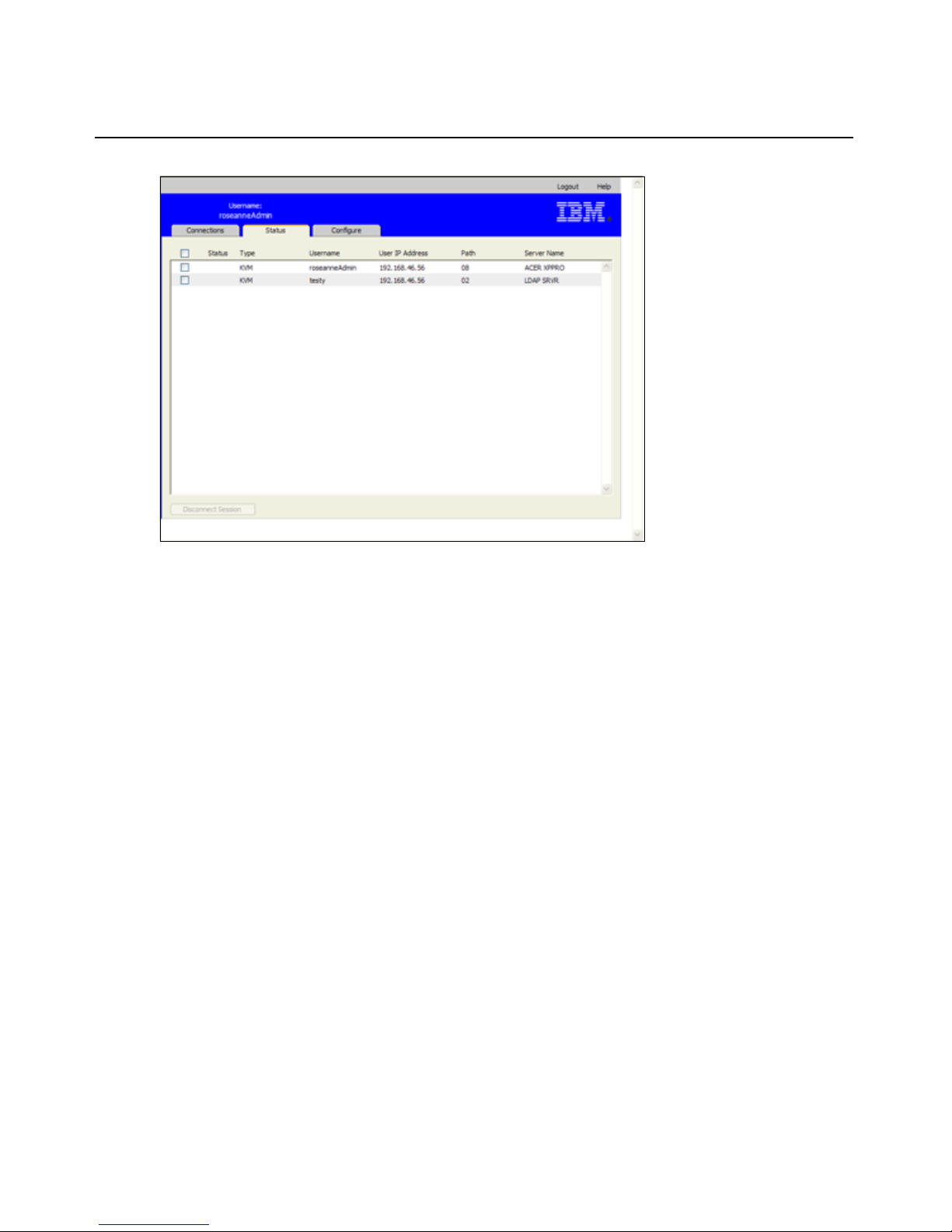
Chapter 3: Using the Web Interface 33
Figure 3.2: Status window
3. To disconnect user session(s), complete the following steps.
a. Select the check box for one or more sessions.
b. Click the Disconnect Session button. A confirmation window appears.
c. Click OK. The Tools window appears.
Overview of viewing and configuring appliance parameters
When the Configure tab is selected, Admin and other users with Appliance Administrator and User
Administrator rights can view appliance information. Users with Appliance Administrator rights
can also configure the appliance. The configuration information is specified in windows that appear
when options are selected from the left menu.
Page 50

34 GCM2 and GCM4 Installation and User’s Guide
Figure 3.3: Configure tab with left menu options and Appliance window
To view appliance information, complete the following steps:
1. Log into the Web interface as a user with Appliance Administrator or User Administrator
rights.
2. Click Configure > Appliance to view the product type, name, description, eID, MAC address,
digitizers (number of digital users supported), number of ARI ports and of local user ports.
Configuring network parameters, KVM sessions, virtual media,
and authentication
When the Configure tab is selected, Admin and other users with Appliance Administrator rights
can also configure the appliance: network parameters, KVM sessions, virtual media sessions, users
and authentication.
To configure network parameters, complete the following steps:
1. Log into the Web interface as a user with Appliance Administrator rights.
2. Click Configure > Appliance > Network to view the MAC address, set the LAN speed, and
enable or disable DHCP.
3. If you disable DHCP, configure a static IP address, subnet mask, gateway IP address, and
optionally specify the IP addresses for up to three DNS servers.
4. Click Save.
Page 51

Chapter 3: Using the Web Interface 35
To configure sessions, complete the following steps:
1. Log into the Web interface as a user with Appliance Administrator rights.
2. Click Configure > Appliance > Sessions.
Figure 3.4: Appliance Sessions window
3. Configure Video Session parameters by performing the following steps.
a. Select the Session Timeout check box and enter a number of minutes to elapse before
inactive video sessions are closed.
b. Select the Video session preemption timeout check box and type a number of seconds
between 5 and 120. This sets a delay between when a preemption warning message is sent
and when the video session is preempted. If the preemption timeout option is not enabled,
preemption occurs without warning.
NOTE: Changes made to video session parameters affect only future sessions.
4. Configure encryption (128, DES, 3DES, AES) by performing the following steps in the
Encryption area of the window. Video encryption is optional but at least one Keyboard/Mouse
encryption level must be set.
a. Select none, one, or more Video encryption check boxes.
b. Select one or more Keyboard/Mouse encryption check boxes.
5. To configure KVM session sharing, select the Enable Share mode check box and complete
the following steps.
a. To enable secondary users to share KVM sessions without req uesting permission from
primary users, select the Automatic check box.
b. To enable primary users to prevent sharing of sessions, select the Exclusive check box.
Page 52

36 GCM2 and GCM4 Installation and User’s Guide
c. To enable administrators to monitor sessions secretly, select the Stealth check box.
d. To specify a time period to elapse before the appliance transfers keyboard and mouse
control from a primary user to a secondary user, enter 1 to 5 seconds in the Input Control
Timeout field.
6. To configure a Login Timeout, enter a time between 20 and 120 seconds. The login timeout
specifies the time allowed for an LDAP server to respond to a login request. The default time is
30 seconds, but some WANs can require a longer time period.
7. To configure an Inactivity Timeout for the Web interface, enter a time between 10 and 60
minutes. If the specified time elapses without the user navigating within the interface or
making changes, the user is logged out of the Web interface.
8. Click Save.
To configure virtual media, comp let e the fo ll o w ing steps:
1. Log into the Web interface as a user with Appliance Administrator rights.
2. Click Configure > Appliance > Virtual Media. The Virtual Media window lists the target
devices that are directly connected to the appliance or that are connected to tiered appliances
that support virtual media using VCO cables.
Figure 3.5: Appliance > Authentication window
3. Under Session Control, complete the following steps.
a. To enable virtual media sessions to continue even after their associated KVM sessions are
closed, clear the Lock to KVM Session check box. This option might be needed, for
example, if operating system upgrades launched during virtual media sessions are
expected to take longer than the KVM session inactivity timeout.
Page 53

Chapter 3: Using the Web Interface 37
b. To lock virtual media sessions to KVM sessions, select the Lock to KVM Session check
box.
c. To allow primary users to have exclusive virtual media sessions, select the Allow
Reserved Sessions check box. Reserved sessions remain active when the associated KVM
session is closed.
d. To allow shared virtual media sessions, clear the Allow Reserved Sessions check box.
e. To enable or disable read-only access to virtual media, select or clear the Read-Only
Access check box.
4. Under Encryption Levels, select none, one, or more of the check boxes for 128, DES, 3DES,
and AES.
5. Click Save.
NOTE: For more information about constraints on virtual media usage, see "Virtual media" on page 91.
To configure authentication, complete the following steps:
1. Log into the Web interface as a user with Appliance Administrator rights.
2. Click Configure > Appliance > Authentication.
Figure 3.6: Appliance > Authentication window
3. To configure authentication using local databases, select the checkbox for Use Local
Authentication and click Save.
4. To configure authentication using LDAP, select the checkbox for Use LDAP Authentication.
Radio buttons become active to allow you to specify the order in which local and LDAP
Page 54

38 GCM2 and GCM4 Installation and User’s Guide
databases are checked. The Authentication Parameters area on the window also becomes
active.
NOTE: Local authentication is always used, whether it is the primary or backup authentication method, and it
cannot be disabled.
5. Select either the Use Local First or Use LDAP First radio button.
6. To specify LDAP to be used for authentication only and the local databases to be used for
authorizations checking, select the Use LDAP for Authentication Only check box.
7. Click the Server tab and configure one or two LDAP enabled directory servers in the Primary
Server and optional Secondary Server areas:
a. Type an address in the IP address field.
b. (Optional) Change the UDP port number in the Port ID field.
c. Configure the access type.
d. Select the LDAP radio button to send queries to the LDAP server in clear text (non-secure
LDAP).
e. Select the LDAPS radio button to send queries using SSH (secureLDAP).
8. To configure the parameters used when searching the LDAP directory service for users, click
the Search tab and complete the following steps.
9. Define a distinguished name (an administrator-level user that the appliance uses to log into the
directory service) in the Search DN field. This is a required field unless the directory service
has been configured to enable anonymous search.
a. Type a password for the user in the Search Password field.
b. Type the starting point for LDAP searches in the Search Base field.
c. Type a mask in the UID Mask field. The default value is correct for use with Active
Directory. This field is required for LDAP searches.
10. To configure the parameters used when searching the LDAP directory service for users, click
the Search tab and complete the following steps.
a. Type a distinguished name for the administrator, which the appliance uses to log into the
directory service, in the Search DN field. This is a required field unless the directory
service has been configured to enable anonymous search.
b. Type a password for the administrator in the Search Password field.
11. Click the Query and configure the modes.
• Appliance query mode is used to authenticate administrators attempting to access the
appliance itself.
• Device query mode is used to authenticate users that are attempting to access attached tar-
get devices.
12. Click Save.
Page 55

Chapter 3: Using the Web Interface 39
Configuring users and user access rights
When the Configure tab is selected, the Admin and other users with Appliance Administrator and
User Administrator rights can click on the Users option in the left menu to configure user accounts.
Figure 3.7: Users window
To configure users and user access rights, complete the following steps:
1. Log into the Web interface as a user with Appliance Administrator or User Administrator
rights.
2. Click the Configure tab.
3. In the left menu, click Users.
4. Click the Add User button. The Add/Modify User window appears.
5. T ype the username and password to assign to the user and then verify the password by typing it
in the Verify Password field. The password must be between 5 and 16 characters and must
contain upper and lowercase alphabetical characters and at least one number.
Page 56

40 GCM2 and GCM4 Installation and User’s Guide
Figure 3.8: Add/Modify User window
6. Click Appliance Administrator, User Administrator, or User from the pull-down User
Access Level menu. If User is selected, the Set User Access Rights button becomes active.
a. Click the Set User Access Rights button to sel ect indi vidual target devices for that
user.The User Access window appears.
Figure 3.9: Users Access window
b. To allow the user access to a target device, select the check box for the device. Select the
first check box to enable access to all target devices.
c. To prevent the user from accessing a target device, clear the check box next to the device
name.
d. Click Save.
Page 57

Chapter 3: Using the Web Interface 41
To change a password, complete the following steps:
1. Log into the Web interface as a user with Appliance Administrator or User Administrator
rights.
2. Click the Configure tab.
3. In the left menu, click Users.
4. Click a user name in the Users column to modify an existing user. The Add/Modify User
window appears.
5. In the Add/Modify User window, type the new password in the Password box and then repeat
the password in the Verify Password box. The password must be between 5 and 16 characters
and must contain upper and lowercase alphabetical characters and at least one number.
6. Click Save.
To delete a user, complete the following steps:
1. Log into the Web interface as a user with Appliance Administrator or User Administrator
rights.
2. Click the Configure tab.
3. In the left menu, click Users.
4. Select the check box next to the user name.
5. Click the Delete button on the left side of the window. A confirmation window appears.
6. Click Yes.
Enabling Security Lock-out and unlocking user accounts
When the Configure tab is selected, the Admin and other users with Appliance Administrator
rights can click the Users option in the left menu to configure the Security Lock-Out feature.
Security lock-out disables a user account if the user enters an invalid password five consecutive
times. The account remains locked until either an administrator-specified number of hours elapses,
the appliances is power-cycled, or an administrator unlocks the account. A User Administrator can
unlock only user accounts; an Appliance Administrator can unlock any type of account.
NOTE: All accounts (User, User Administrator, and Appliance Administrator) are subject to the lock-out policy.
To enable lock-outs, complete the following steps:
1. Log into the Web interface as a user with Appliance Administrator or User Administrator
rights.
2. Click the Configure tab and then click Users in the left menu.
3. Select the Enable Lock-outs check box.
4. Type a number of hours (1 to 99) in the Duration field.
Page 58

42 GCM2 and GCM4 Installation and User’s Guide
To unlock an account, complete the following steps:
1. Log into the Web interface as a user with Appliance Administrator or User Administrator
rights.
2. Click the Configure tab and then click Users in the left menu.
3. Select the check box next to the user name.
4. Click the Unlock button. The lock icon next to the username disappears.
To disable the security lockout, complete the following steps:
1. Log into the Web interface as a user with Appliance Administrator rights.
2. Click the Configure tab and then click Users in the left menu.
3. Clear the Enable Lock-outs check box. The Duration field is disabled.
NOTE: Disabling Security Lock-Out does not affect users that are already locked out.
Configuring SNMP
When the Configure tab is selected, the Admin and other users with Appliance Administrator
rights can click the SNMP option in the left menu to configure SNMP. SNMP managers, such as
Tivoli and HP OpenView, can communicate with the appliance by accessing MIB-II and the public
portion of the enterprise MIB.
The administrator can do the following SNMP configuration:
• Enable or disable SNMP.
• Enter appliance information and community strings.
• Restrict which SNMP servers can manage the appliance by identifying a set of allowable
SNMP managers. If no allowable SNMP servers are specified, any SNMP manager can monitor the appliance from any IP address.
• Specify SNMP servers as destinations for SNMP traps from the appliance. If no destinations
are specified, no traps are sent.
The Web interface retrieves the SNMP parameters from the appliance. If Enable SNMP is selected,
the unit responds to SNMP requests over UDP port 161. For third-party SNMP management
software to monitor the appliance, UPD port 161 must be exposed on the firewall.
Under Configure > SNMP, appliance administrators can enter system information and community
strings and can specify SNMP servers to manage the appliance and specify other SNMP servers to
receive SNMP traps from the appliance. For more information on traps, see "Configuring SNMP
traps" on page 43.
Page 59

Chapter 3: Using the Web Interface 43
Figure 3.10: SNMP Configuration window
To configure general SNMP settings, complete the following steps:
1. Log into the Web interface as a user with Appliance Administrator rights.
2. Click the Configure tab, and then click SNMP in the left menu.
3. Select or clear the Enable SNMP check box to enable or disable SNMP.
4. If SNMP is enabled, complete the following steps:
a. Type the fu lly qualified domain name for the system in the Name field and the name of a
contact person in the System section. Both fields have a limit of 255 characters.
b. Type Read, Write, and Trap community names. These specify the community strings
that must be used in SNMP actions. The Read and Write strings only apply to SNMP
over UDP port 161 and act as passwords that protect access to the appliance. The values
can be up to 64 characters in length. These fields can not be left blank.
c. Type the IP address of up to four management servers in the Allowable Managers fields,
or leave the fields blank to allow any SNMP management server to manage the appliance.
d. Type the IP address of up to four management servers to which this appliance will send
traps in the Trap Destination fields. If no IP addresses are specified, no traps are sent.
5. Click Save.
Configuring SNMP traps
When the Configure tab is selected, the Admin and other users with Appliance Administrator
rights can click the SNMP > Traps option in the left menu to configure which traps are enabled
and disabled. OpenManage™ IT Assistant software is the event manager.
Page 60

44 GCM2 and GCM4 Installation and User’s Guide
Figure 3.11: SNMP Traps Window
To configure SNMP traps, complete the following steps:
1. Log into the Web interface as a user with Appliance Administrator rights.
2. Click the Configure tab and then click SNMP > Traps in the left menu.
3. Select or clear the Enabled Traps check box to enable or disable traps.
4. If SNMP traps are enabled, select the check box to enable each SNMP trap.
5. Click Save.
Page 61

Chapter 3: Using the Web Interface 45
Viewing target device information and naming target devices
When the Configure tab is selected, the Admin and other users with Appliance Administrator and
User Administration rights can click the Servers option in the left menu to view information about
target devices. Users with Appliance Administrator rights can configure names for target devices.
• The Server Name column lists the connected target devices whether they are connected to an
ARI port on the appliance or to a port on a tiered appliance or switch (cascade device).
• The eID column displays the eID stored on the CO cable.
• The number in the Path column indicates the number of the port where the target device is
connected whether the device is connected to a port on the main appliance or to a port on a
tiered appliance or switch.
Figure 3.12: Servers window
Clicking on a Server Name displays a Modify Server Name window.
Figure 3.13: Modify Server Name window
Page 62

46 GCM2 and GCM4 Installation and User’s Guide
To modify the name of a target device, complete the following steps:
1. Log into the Web interface as a user with Appliance Administrator rights.
2. Click the Configure tab and then click Servers in the left menu.
3. Click the name of the server. The Modify Server Name window appears.
4. Type the name for the server. Names must have between 1 and 15 characters, can include
alphabetical and numeric characters, and can not include spaces or special characters with the
exception of hyphens.
5. Click Save.
Viewing CO cable information and setting a CO language
When the Configure tab is selected, the Admin and other users with Appliance Administrator or
User Administration rights can click the Servers > COs option in the left menu to view information
about each CO cable in the system, its Electronic ID number (EID), its Path (port), its CO cable
type and the type of target device to which it is connected.
Users with Appliance Administrator rights can also clear offline COs from the list and set the
language that is recorded in USB CO cables and on the target device to match the language of the
local keyboard.
NOTE:It is not possible to clear offline COs that are connected to a tiered analog appliance.
NOTE:All offline COs connected to GCM2 and GCM4 appliances are cleared, including those
associated with any powered dow n Servers.
NOTE:User device access rights are changed to remove target devices associated with cleared
offline COs.
Table 3.3: CO cable status symbols
Symbol Description
The CO cable is online (green circle).
The CO cable is offline or is not operating correctly.
The CO cable is being upgraded (yellow circle).
Page 63

Chapter 3: Using the Web Interface 47
Figure 3.14: Servers - COs window
Viewing and configuring cascade devices
When the Configure tab is selected, the Admin and other users with Appliance Administrator or
User Administration rights can click the Servers > Cascade Devices option in the left menu to
view information about each cascade device (either a GCM2 or GCM4 appliance or legacy
switches tiered from the appliance): its Electronic ID number (EID), its Path (port), and the number
of channels on the cascade device.
Users with Appliance Administrator rights can click a cascade device name to bring up the Modify
Cascade Device window for changing the device name or number of channels.
Figure 3.15: Modify Cascade Device window
NOTE: Then channels on cascade devices are not automatically detected. Appliance administrators must use
this window to manually specify the number of channels (ports) on each cascade device.
Page 64

48 GCM2 and GCM4 Installation and User’s Guide
To configure a cascade device name and the number of channels, complete the following
steps:
1. Log into the Web interface as a user with Appliance Administrator rights.
2. Click the Configure tab, and then click Cascade Devices in the left menu.
3. Click the name of the cascade device. The Modify Cascade Device window opens.
4. Type the new name for the device.
5. Type the number of channels, between 4 and 24, for the device.
6. Click Save.
Viewing software and firmware versions for the appliance
When the Configure tab is selected, any user can click the Versions option in the left menu to view
version information about software and firmware on the appliance.
Figure 3.16: Versions window
Viewing CO cable version information and administering
firmware
When the Configure tab is selected, any user can click Versions > CO in the left menu to view
information about each CO cable: its Name, eID, Path, and Type. Any user can also click on an eID
for a CO cable to view Application, Boot, and Hardware version information and whether updated
firmware is available for the selected CO cable.
Page 65

Chapter 3: Using the Web Interface 49
Admin and other users with Appliance Administrator rights can configure firmware upgrades for
individual CO cables and enable automatic firmware upgrades for CO cables.
Appliance Administrators can upgrade all CO cables of the same type at once in the Tools tab. See
"Using the Tools" on page 51.
Selecting the Enable Auto-Upgrade for all COs check box causes automatic upgrades of all
subsequently connected CO cables to the firmware level available on the appliance. This
guarantees that CO cable firmware is compatible with the appliance firmware.
Admin and other users with Appliance Administrator rights can use this window to reset a KCO
cable if it is connected to a tiered switch, which can be necessary if the appliance stops recognizing
the tiered switch.
Figure 3.17: COs Firmware Version Window
To view version information for a CO cable, complete the following steps:
1. Log into the Web interface as any user.
2. Click the Configure tab, and then click Versions > CO Versions in the left menu.
3. Click the eID of the CO cable. A window displays the CO version information.
Page 66

50 GCM2 and GCM4 Installation and User’s Guide
Figure 3.18: CO Version window
4. Click the X in the upper right of the window to return to the CO Versions window.
To configure automatic or individual CO cable firmware upgrades, complete the following
steps:
1. Log into the Web interface as a user with Appliance Administrator rights.
2. Click the Configure tab, and then click Versions > CO in the left menu.
3. To enable automatic upgrades of subsequently connected CO cables, complete the following
steps.
a. Click the Enable Auto-Upgrade for all COs button. A confirmation window appears.
b. Click OK to continue.
4. To load and upgrade CO cable firmware, complete the following steps:
a. Clic k the eID of the CO cable. The CO Version windo w opens.
b. Compare the Application version to the Firmware Available Application version show.
(You can load firmware even if the current and available versions are the same. In some
cases, you can downgrade the CO cable to an older, compatible version.)
c. Click the Load Firmware button. The firmware upgrade begins. Du ring the upgrade, a
progress message is displayed below the Firmware Available box and the Load
Firmware button dims. When the upgrade is finished, a message appears indicating that
the upgrade was successful.
d. Click the X in the upper right of the CO Version window to return to the CO Versio ns
window.
e. Repeat steps a-d for each individual CO cable to upgrade.
Page 67

Chapter 3: Using the Web Interface 51
To reset a CO cable, complete the following steps:
1. Log into the Web interface as a user with Appliance Administrator rights.
2. Click the Configure tab, and then click Versions > CO in the left menu.
3. Click the eID of the KCO cable you want to reset. The CO Version window opens.
4. Click the Reset CO button. A confirmation window appears.
5. Click OK to continue.
6. When the reset completes, click the X in the upper right of the CO Version window to return to
the CO Versio ns window.
Using the Tools
When the Tools tab is selected, Admin and other users with Appliance Administrator rights can
click any of the buttons on the Tools window to do the specified tasks.
Figure 3.19: Tools tab
Rebooting the appliance using the Tools
When the Tools tab is selected, Admin and other users with Appliance Administrator rights can
reboot the appliance by clicking the Reboot Appliance button in the Tools tab. Appliance
Administrators can also reboot the appliance by clicking the Reboot Required button whenever it
appears after a configuration change. When Reboot Appliances is clicked, a disconnect message is
broadcast to any active users, the current user is logged out and the appliance is immediately
rebooted.
Page 68

52 GCM2 and GCM4 Installation and User’s Guide
To reboot the appliance using the Tools, complete the following steps:
1. Log into the Web interface as a user with Appliance Administrator rights.
2. Click the Tools tab. The Tools window appears.
3. Click the Reboot Appliance button. A confirmation window appears.
4. Click OK. The appliance reboot takes about one minute.
Upgrading the appliance firmware using the Tools
When the Tools tab is selected, Admin and other users with Appliance Administrator rights can
click the Upgrade Appliance Firmware button to upgrade appliance firmware that has been
downloaded either into the file system of the computer that is running the Web interface or onto a
TFTP server. When an upgrade is initiated, a progress bar appears. As long as an upgrade is in
progress, you cannot start another.
NOTE: If you are updating an appliance to a firmware version that provides support for the Web interface, you
need to use the VCS as described in "Upgrading GCM2 and GCM4 appliances to use the Web interface" on
page 25 to upgrade the firmware, migrate and resync the appliance after the upgrade.
To upgrade appliance firmware, complete the following steps:
1. Download the appliance firmware from http://www.ibm.com/support/ either to a TFTP server
or to the current computer.
2. Log into the Web interface as a user with Appliance Administrator rights.
3. Click the Tools tab. The Tools window appears.
4. Click the Upgrade Appliance Firmware button. The Upgrade Appliance Firmware
window appears.
5. To upgrade firmware from a TFTP server, select the TFTP Server radio button, type the IP
address in the Server IP Address field, and type the pathname in the Firmware File field.
Figure 3.20: Upgrade Appliance Firmware window- TFTP server
Page 69

Chapter 3: Using the Web Interface 53
6. To upgrade firmware from the current computer, select the File System radio button and
browse to the location on your file system where the firmware file is located. Click Open.
Figure 3.21: Upgrade Appliance Firmware window - file system
7. Click the Upgrade button. The Upgrade button dims and a progress message and progr ess bar
appears.
8. When the upgrade is complete, the Reboot Appliance window appears.
9. Click Yes to reboot the appliance.
10. When the notice “Firmware Upgrade has completed. The Appliance is ready” appears, click
Close to exit the Upgrade Appliance Firmware window.
11. Perform the steps in this procedure until all appliances are upgraded.
12. Click OK.
NOTE: Do not turn appliance power off while the appliance firmware is being upgraded.
Upgrading firmware on multiple CO cables using the Tools
When the Tools tab is selected, Admin and other users with Appliance Administrator rights can
click the Upgrade CO Firmware button to upgrade firmware for multiple CO cables.
To upgrade firmware on multiple CO cables, complete the following steps:
1. Log into the Web interface as a user with Appliance Administrator rights.
2. Click the Tools tab. The Tools window appears.
3. Click the Upgrade CO Firmware button. The Upgrade CO Firmware window appears.
4. Select the check box in front of each CO cable type (PS2,USB,USB2,SRL,Sun) to upgrade.
NOTE: A disabled check box indicates that all CO cables of that type are running the current firmware, or that no
CO cable of that type exists in the system.
Page 70

54 GCM2 and GCM4 Installation and User’s Guide
Figure 3.22: Upgrade CO Firmware window
5. Click Upgrade. The Upgrade button dims. The Last Status column displays either In
Progress or Succeeded, depending on the status of each CO cable upgrade. A firmware
upgrade currently in progress message displays until all of the selected CO cable types are
upgraded. A confirmation window appears.
6. Click OK. The Upgrade Firmware window appears with the Upgrade button is enabled.
7. Click Close to exit the Upgrade Firmware window and return to the Tools window.
Managing appliance configuration files
When the Tools tab is selected, Admin and other users with Appliance Administrator rights can
click the Save Appliances Configuration button to save appliance configuration into a file and
click the Restore Appliance Configuration button to restore the file.
An Appliance configuration file stores all appliance settings, including SNMP settings, LDAP
settings, and NTP settings. The file can be stored anyplace in the file system of the current
computer. A saved appliance configuration file can be restored to a new or upgraded appliance to
avoid manual configuration or reconfiguration.
NOTE: User account information is stored in the user configuration file. See "Managing user databases" on
page 56.
To save appliance configuration, complete the following steps:
1. Log into the Web interface as a user with Appliance Administrator rights.
2. Click the Tools tab. The Tools window appears.
3. Click the Save Appliances Configuration button. The Save Appliance Configuration
window appears.
Page 71

Chapter 3: Using the Web Interface 55
Figure 3.23: Save Appliance Configuration window
4. (Optional) Enter a password in the File Password field, then repeat the password in the Verify
File Password field. If a file password is configured, the administrator must supply this
password when attempting to restore the appliance configuration.
5. Click Save. A confirmation window appears.
6. Click Save. A Save As window appears
7. Navigate to the file system location where you want to store the file. Enter a File Name.
8. Click Save. The configuration file is saved to the desired location. A progress window
displays.
9. When the Download Complete message appears, click Close to close the progress window.
10. Click the X in the upper right of the Save Appliance Configuration window to return to the
Tools window .
To restore a saved appliance configuration, complete the following steps:
1. Log into the Web interface as a user with Appliance Administrator rights.
2. Click the Tools tab. The Tools window appears.
3. Click the Restore Appliances Configuration button. The Restore Appliance Configuration
window appears.
Page 72

56 GCM2 and GCM4 Installation and User’s Guide
Figure 3.24: Restore Appliance Configuration window
4. Click Browse and navigate to the location where the saved configuration file is stored. The file
name and location appear in the File name field.
5. If a file password was created, enter it in the File Password field.
6. Click Restore. When the restoration is complete, a confirmation window appears.
7. Click OK to return to the Tools window.
Managing user databases
When the Tools tab is selected, Admin and other users with Appliance Administrator rights can
click the Save Appliance User Database button to save appliance configuration into a file and
click the Restore Appliance User Database button to restore the file.
The user database file stores the configuration for all user accounts on the appliance. A saved user
database file can be restored to a new or upgraded appliance to avoid manual configuration or
reconfiguration of users.
To save the appliance user database, complete the following steps:
1. Log into the Web interface as a user with Appliance Administrator rights.
2. Click the Tools tab. The Tools window appears.
3. Click the Save Appliance User Database button. The Save Appliance User Data window
appears.
Page 73

Chapter 3: Using the Web Interface 57
Figure 3.25: Save Appliance User Data window
4. (Optional) Enter a password in the File Password field, then repeat the password in the Verify
File Password field. If a file password is configured here, the administrator must supply this
password to restore the appliance configuration.
5. Click Save. A confirmation window appears.
6. Click Save. A File Download - Security Warning window appears.
7. Navigate to the file system locat ion for storing the file. Enter a na me for the user d ata file in the
File Name field.
8. Click Save. The data file is saved to the specified location. A progress window displays.
9. When the Download Complete message appears, click Close to close the progress window.
10. Click the X in the upper right of the Save Appliance User Data window to return to the Tools
window.
11. A confirmation window appears.
12. Click OK.
To restore the appliance user database, complete the following steps:
1. Log into the Web interface as a user with Appliance Administrator rights.
2. Click the Tools tab. The Tools window appears.
3. Click the Restore Appliance User Database button. The Restore Appliance User Data
window appears.
Page 74

58 GCM2 and GCM4 Installation and User’s Guide
Figure 3.26: Restore Appliance User Data window
4. Click Browse and navigate to the location where the saved user data file is stored.
5. Select the file. The file name and location appear in the File name field.
6. If a file password was created, enter it in the File Password field.
7. Click Restore. When the restoration is complete, a confirmation window appears.
8. Click OK to return to the Tools window.
Page 75

59
Using the OSCAR interface
You can connect a keyboard, monitor, and mouse to local ports on the back of the appliance to act
as a local user station for direct analog access. A local user can then use the OSCAR interface to
configure the switching system and access target devices.
OSCAR interface Main window
The following illustration is an example of the Main window of the OSCAR interface.
Figure 4.1: Example of a Main window
The Main window lists the target devices connected to the switching system. You can order the list
by target device names, eID numbers, or port numbers by clicking the Name, eID, or Port button.
The Port column indicates the ARI port to which each target device is connected. If an earliermodel appliance or switch (called a cascade device) is connected to a GCM2 or GCM4 appliance,
the ARI port number on the main appliance where the cascade device is connected is shown first,
followed by the number of the port on the cascade device to which the target device is connected.
For example, in Figure 4.1, the target device named Acton is connected to a cascade device that is
connected to ARI port 06; the target device is connected to port 01 on the cascade device.
CHAPTER
4
Page 76

60 Global Console Manager Installation and User’s Guide
The status of each target device in the switching system is indicated by one or more status symbols
in the right column. The following table describes the status symbols.
To start the OSCAR interface, complete the following steps:
1. Turn on the monitor connected to the local user ports.
2. Start the OSCAR interface by performing one of the following steps.
•Press Print Screen.
•Press the Ctrl, Alt, or Shift key twice within 1 second to start the OSCAR interface.
NOTE: You can use any of these key sequences instead of pressing Print Screen in any procedure in this
chapter.
3. If a password is set, the Password window opens. Type the password and click OK.
To set an OSCAR interface startup delay, complete the following steps:
1. Start the OSCAR interface.
2. In the Main window, click Setup > Menu.
3. In the Screen Delay Time field, type a number of seconds.
Table 4.1: OSCAR interface status symbols
Symbol Description
The CO cable is online (green circle).
The CO cable is offline or is not operating correctly.
The target device is tiered through another appliance. The target device and the appliance
are online and have power.
The target device is tiered through another appliance. The appliance is offline or does not
have power.
The CO cable is being upgraded (yellow circle). When this symbol is visible, do not tu rn off
and turn on the appliance or connected target devices and do not disconnect the CO cable.
Doing so might damage the CO cable permanently.
The CO cable is being accessed by the indicated user channel (green channel letter).
The CO cable is blocked by the indicated user channel (black channel letter). For instance,
in Figure 3.1, user C is viewing Forester, but is blocking access to Acton, Barrett, and Edie
which are connected to the same CO cable.
A remote virtual media connection is established to the target device connected to the
indicated user channel (blue letter).
Page 77

Chapter 4: Using the OSCAR interface 61
Using the OSCAR interface
This table describes the keys, key combinations, and mouse actions that you can use in the OSCAR
interface. Two or more key names or mouse actions that are separated by commas indicate a
sequence of actions. Two or more key names or mouse actions that are separated by a plus sign (+)
indicate a combination of actions; that is, they are performed simultaneously.
You can use the main keyboard or the numeric keypad to type numerals, except when you use the
Alt+0 key combination; you must use the 0 key on the main keyboard when you use Alt+0.
Table 4.2: OSCAR interface navigation basics
Key, key combination, or
mouse action
Result
Print Screen; Ctrl, Ctrl; Shift,
Shift; or Alt, Alt
Start the OSCAR interface. To specify which key sequences can be
used to start the OSCAR interface, click Setup > Menu.
Print Screen, Print Screen
Send the Print Screen keystroke to the currently selected target
device. In other words, a screen capture will be performed for the
target device.
If Print Screen is not selected as startup key sequence in Setup >
Menu, you only need to press Print Screen once to take a screen
capture of the target device.
F1 Display help for the current window.
Escape
In the OSCAR main window: Close the OSCAR interface and return to
the status flag on the desktop.
In all other windows: Close the current window, without saving
changes, and return to the previous window.
In pop-up windows: Close the pop-up window and return to the
current window.
Alt+X
Close the current window, without saving changes, and return to the
previous window.
Alt+O
Click OK and return to the previous window.
Alt+port number
Select a target device to be scanned; port number is the port number
of the target device.
Enter
Completes a switch in the Main window and exits the
OSCAR interface.
Click on an editable field to select the text for editing and enable the
Left and Right arrow keys to move the cursor. Press Enter to quit the
edit mode.
Print Screen, Backspace Return to the previously selected target device.
Print Screen, Alt+0
Disconnect the user from the selected target device. Note that the
zero must be typed on the main keyboard, not the numeric keypad.
Page 78

62 Global Console Manager Installation and User’s Guide
Connecting to a target device
Use the Main window of the OSCAR interface to select a target device to which you want to
connect. When you select a target device, the keyboard and mouse are automatically reconfigured
to the correct settings for that target device.
To select a target device, complete the following steps:
1. Start the OSCAR interface.
2. Use one of the following options in the Main window to select the device:
• Double-click the target device name, eID number, or port number.
• Type the port number, and press Enter.
• Type the first few unique characters of the target device name or eID number, and press
Enter.
3. You can toggle between two selected target devices. To select the previously selected target
device, press Print Screen and press Backspace.
To disconnect from a target device, perform the following step:
Press Print Screen and press Alt+0. A Free status flag in the OSCAR interface indicates that the
user is not connected to a target device.
Configuring and starting local virtual media sessions
You can start a virtual media session with a target device through the OSCAR interface only when
a USB media device is connected directly to the appliance using a USB port on the appliance.
Print Screen, Pause
Start the screen saver immediately and lock the user, if it is
password-protected.
Up Arrow or Down Arrow Move the cursor from line to line in a list.
Right Arrow or Left Arrow
When editing text in a field: Move within the text in the field.
All other conditions: Move the cursor from column to column in a list.
Page Up or Page Down Page through a list or help window.
Home or End Move the cursor to the top or bottom of a list.
Delete
Delete the selected characters in a field or the selected item in the
scan list. For more information about scan lists see “Scanning the
switching system” on page 78.
Table 4.2: OSCAR interface navigation basics (Continued)
Key, key combination, or
mouse action
Result
Page 79

Chapter 4: Using the OSCAR interface 63
Virtual media sessions created in any manner require that the target device is connected using a
VCO cable.
NOTE: All USB ports are assigned to a single virtual media session and cannot be independently mapped.
To configure virtual media sessions, complete the following steps:
1. Start the OSCAR interface.
2. Select the target device.
3. Click the VMedia button. The Virtual Media window opens.
4. To specify that ending a KVM session also ends a virtual media session, select the Locked
check box.
5. To specify that a user can reserve a virtual media session so that no other user can connect,
select the Reserve check box.
6. To enable the target device to write data to the virtual media during a virtual media sessions,
select the Write Access check box. Read access is always enabled during virtual media
sessions.
7. Click OK.
To start a local virtual media session, complete the following steps:
1. Start the OSCAR interface.
2. Select the target device.
3. Click the VMedia button. The Virtual Media window opens.
4. T o map a CD ROM device connected to the appliance so that its icon appears on the desktop of
the target device, select the CD ROM check box. Clear this check box to end the mapping.
5. To map a USB storage device (diskette or hard drive) that is connected to the appliance so that
its icon appears on the desktop of the target device, select the Mass Storage check box. Clear
this check box to end the mapping.
6. Click OK.
Page 80

64 Global Console Manager Installation and User’s Guide
Configuring the appliance and the OSCAR interface
You can use the OSCAR interface Setup window to configure the appliance and the OSCAR
interface.
Figure 4.2: Setup window
The following table describes the options in the Setup window.
Table 4.3: Setup features to manage routine tasks for the target devices
Option Purpose
Menu
Order the list of target devices by target device name, eID number, or port number.
Set a screen delay to specify the length of time that elapses between when Print
Screen is pressed and when the OSCAR interface starts.
Security Enable the screen saver. Set a password to restrict access to the target devices.
Flag Change the display properties including timing, color, and location of the status flag.
Language Specify the language that the interface is displayed in.
Devices Specify the number of ports that are on the attached tiered appliance.
Names Assign a unique name to each target device.
Keyboard Specify the keyboard country code.
Broadcast Simultaneously control multiple target devices through keyboard and mouse actions.
Scan Set up a custom scan pattern for up to 16 target devices.
Preempt Specify preemption settings.
Network
Specify the network speed and configuration, IP address, netmask, and gateway for
the switching system.
Page 81

Chapter 4: Using the OSCAR interface 65
Assigning target device names
Use the Names window to identify individual target devices by name rather than by port number.
The Names list is always sorted by port order. Names are stored in the CO cable, so even if you
move the cable or target device to another ARI port, the name and configuration are recognized
by the appliance. If a target device is turned off, you cannot modify the name of the CO cable.
To access the Names window, complete the following steps:
1. Start the OSCAR interface.
2. Click Setup > Names. The Names window opens.
Figure 4.3: Names window
If new CO cables are discovered by the appliance, the on-screen list will be automatically updated.
The mouse cursor will change into an hourglass during the update. No mouse or keyboard input
will be accepted until the list update is complete.
Page 82

66 Global Console Manager Installation and User’s Guide
To assign names to target devices, complete the following steps:
1. In the Names window, select a target device and click Modify. The Name Modify window
opens.
Figure 4.4: Name Modify window
2. Type a name in the New Name field. Names can be up to 15 characters long. Valid characters
are A through Z, a through z, 0 through 9, space, and hyphen.
3. Click OK. The selection is not saved until you click OK in the Names window.
4. Repeat steps 1 to 3 for each target device in the switching system.
5. Click OK in the Names window to save the changes , or click X or press Escape to exit without
saving changes.
If a CO cable has not been assigned a name, its eID is used as the default name. To list target
devices alphabetically by name, press Alt+N or click Name in the Main window.
Configuring ports on cascade devices
The GCM2 or GCM4 appliance automatically discovers attached tiered appliances and switches
(cascade devices), but you must specify the number of ports on each cascade device through the
Devices window. IBM Console Switches and other earlier-model appliances are listed in the Type
category for the tiered appliance.
Page 83

Chapter 4: Using the OSCAR interface 67
Figure 4.5: Devices window
When the appliance discovers a tiered appliance or switch, the port numbering changes to identify
each connected target device.
When you select a configurable target device from the list, the Modify button becomes available,
so you can configure the correct number of ports.
To access the Devices window, complete the following steps:
1. Start the OSCAR interface.
2. Click Setup > Devices. The Devices window opens.
To assign a device type, complete the following steps:
1. In the Devices window, select the port number of the cascade device.
2. Click Modify. The Device Modify window opens.
Figure 4.6: Device Modify window
3. Select a radio button or type the number of ports on the cascade device and click OK.
4. Repeat steps 1 to 3 for each cascade appliance.
5. Click OK in the Devices window to save settings.
Page 84

68 Global Console Manager Installation and User’s Guide
Changing the display behavior
Use the Menu window to change the order of the target devices and set a screen delay for the
OSCAR interface. The display order setting affects the order in which target devices are listed in
several windows, including the Main, Devices, and Broadcast windows.
To access the Menu window, complete the following steps:
1. Start the OSCAR interface.
2. Click Setup > Menu. The Menu window opens.
Figure 4.7: Menu window
To specify the order of target devices, complete the following steps:
1. In the Menu window, select one of the following check boxes:
• Select Name to list the target devices alphabetically by target device name.
• Select eID to list the target devices numerically by eID number.
• Select Port to list the target devices numerically by port number.
2. Click OK.
To specify a key combination to start the OSCAR interface, complete the following steps:
1. In the Menu window, in the Invoke OSCAR section, press one of the following keys or
combinations of keys to specify which key starts the OSCAR interface:
• Print Scrn
• Ctrl-Ctrl
• Alt-Alt
• Shift-Shift
2. Click OK.
Yo u can set a screen delay so that a target device can be selected using the keyboard without
starting the OSCAR interface. A screen delay specifies the length of time that elapses between
Page 85

Chapter 4: Using the OSCAR interface 69
when Print Screen is pressed and when the OSCAR interface starts. T o set a sc reen delay, complete
the following steps:
1. In the Menu window, in the Screen Delay Time section, type the number of seconds (0
through 9) to specify the length of delay. If you specify 0, there is no delay.
2. Click OK.
Selecting the display language
Use the Language window to change the display language for the OSCAR interface.
Figure 4.8: Language window
To select a language for the OSCAR interface, complete the following steps:
1. Start the OSCAR interface.
2. Click Setup > Language. The Language window opens.
3. In the Language window, select the language and click OK.
Configuring the status flag
The status flag is displayed on the desktop of the target device in the Video Viewer and indicates
the name or eID number of the selected target device or the status of the selected port. You can
specify the information that is displayed in the flag, the flag color, whether the desktop is visible
through the flag, whether the flag is displayed all the time, and where the flag is displayed on the
desktop. The following table shows examples of status flags.
Table 4.4: OSCAR interface status flags
Flag Description
Flag type by name.
Flag type by eID number.
Page 86

70 Global Console Manager Installation and User’s Guide
To specify the status-flag settings, complete the following steps:
1. Start the OSCAR interface.
2. Select Setup > Flag.
Figure 4.9: Flag Setup window
3. Click or more of the following check boxes:
• Select Name or eID to specify the information that is displayed in the flag.
• Select Displayed to display the flag all the time, or select Timed to display the flag for only 5
seconds after you select a target device.
•In the Display Color section, select a flag.
• Select Opaque to make the flag solid, or select Transparent to make the desktop visible
through the flag.
4. To specify the position of the flag, complete the following steps:
a. Click the Set Position button .
b. Hold down the left mouse button on the title bar of the Set Position window, and drag the
window to the new location.
c. Press th e right mouse button to close the Set Position window.
Flag indicating that the user has been disconnected from all systems.
Flag indicating that Broadcast mode is enabled.
Table 4.4: OSCAR interface status flags (Continued)
Flag Description
Page 87

Chapter 4: Using the OSCAR interface 71
Figure 4.10: Set Position window
5. Click OK to save the changes, or click X or press Escape to exit without saving the changes.
Setting the keyboard country code
By default, the appliance sends the US keyboard country code to USB cables attached to target
devices, and the code is applied to the target devices when they are turned on or rebooted. Codes
are then stored in the CO cable. Using a keyboard code that supports a language different from that
of the appliance firmware will cause incorrect keyboard mapping.
If multiple keyboards are connected to the local port, they must be of the same type (PC or Mac)
and of the same language. Only local users can view or change keyboard country code settings.
Issues might arise when you use the US keyboard country code with a keyboard of another country.
For example, the Z key on a US keyboard is in the same location as the Y key on a German
keyboard.
You can use the Keyboard window to send a different keyboard country code than the default US
setting.
Figure 4.11: Keyboard window
To change the keyboard country code, complete the following steps:
1. Start the OSCAR interface.
2. Click Setup > Keyboard. The Keyboard window opens.
3. Select the country code for the keyboard, and click OK. Confirm the change in the Keyboard
Warning window.
4. Click OK to save the change, or click X or press Escape to exit without saving the change.
Page 88

72 Global Console Manager Installation and User’s Guide
Setting appliance security
When a password is not set, anyone with access to the local user station can access the OSCAR
interface. For security, enable the screen saver and set an OSCAR interface password.
You can specify an inactivity timeout for the screen saver. When the screen saver starts, any target
device connections are ended. The screen saver stops when you press any key or move the mouse.
When a password is set, you must type the password and click OK to turn off the screen saver. A
password must contain both alphabetic and numeric characters and can be up to 12 characters long.
Passwords are case-sensitive. Valid characters are A through Z, a through z, 0 through 9, space, and
hyphen.
Important: If you forget the password, you must call technical support. See “Appendix E”
beginning on page 97 for contact information.
To immediately start the screen saver, perform the following step:
Press Print Screen and press Pause.
To access the Security window, complete the following steps:
1. Start the OSCAR interface.
2. Click Setup > Security. The Security window opens.
To enable the screen saver, complete the following steps:
1. In the Security window, select the Enable Screen Saver check box.
2. In the Inactivity Time field, type the number of seconds (1 through 99) of inactivity before the
screen saver starts.
3. If the monitor is Energy Star compliant, select Energy; otherwise, select Screen.
4. (Optional) To run the screen-saver test, click Test. The screen-saver test runs for 10 seconds.
5. Click OK.
To disable the screen saver, complete the following steps:
1. In the Security window, clear the Enable Screen Saver check box.
2. Click OK.
To set or change a password, complete the following steps:
1. In the Security window, double-click the New field.
2. In the New field, type the new password.
3. In the Repeat field, type the password again.
4. Click OK.
Page 89

Chapter 4: Using the OSCAR interface 73
To disable password protection, complete the following steps:
1. In the Security window, double-click the New field. Leave the field blank, and press Enter.
2. Double-click the Repeat field. Leave the field blank, and press Enter.
3. Click OK.
Setting the preemption warning
Administrators and users with certain access rights can preempt (disconnect) KVM sessions and
take control of the target device. You can choose whether or not to warn the primary user before
preempting a KVM and specify how long the appliance waits for the primary user to respond to the
warning.
For more information about preempting sessions and preemption settings, see the VCS Installation
and User’s Guide.
To view or change the preemption warning settings, complete the following steps:
1. Start the OSCAR interface.
2. Click Setup > Preempt.
3. Enter a number of seconds in the Timeout Seconds field.
• If you enter a value of 0 to 4 seconds, the first user will not be warned before the session
is preempted.
• If you enter a value of 5 to 120 seconds, the first user will be warned and will be allowed
to continue using the target device for up to the amount of time in the Timeout Seconds
field. The session will be preempted when the user clicks OK, or when the specified
time elapses.
4. Click OK to save the settings.
Figure 4.12: Preempt window
Page 90

74 Global Console Manager Installation and User’s Guide
Managing target device tasks using the OSCAR interface
From the Commands window, you can manage the switching system and user connections, enable
the Scan and Broadcast modes, and update the firmware.
Figure 4.13: Commands window
To access the Commands window, complete the following steps:
1. Start the OSCAR interface.
2. Click Commands. The Commands window opens.
Displaying version information
You can use the OSCAR interface to view the versions of the appliance and the CO cable
firmw ar e . F or m or e i nf o r m a ti o n , s e e “Appen dix A” beginning on page 89.
Table 4.5: Commands to manage routine tasks for the target device
Feature Purpose
CO Status View the version and upgrade status of the CO cable.
Display Config View current display settings.
Run Diagnostics Configure and begin diagnostics on target devices.
Broadcast Enable
Begin broadcasting to the target devices. Configure a target device list for
broadcasting under the Setup window.
Scan Enable
Begin scanning the target devices. Set up a target device list for scanning in the
Setup window.
User Status View and disconnect users.
Display Versions
View version information for the appliance as well as view and upgrade firmware for
individual CO cables.
Device Reset Re-establish operation of the keyboard and mouse.
Page 91

Chapter 4: Using the OSCAR interface 75
To view version information, complete the following steps:
1. Start the OSCAR interface.
2. Click Commands > Display Versions. The Version window opens. The top pane of the
window lists the subsystem versions in the appliance.
Figure 4.14: Version window
3. Click the CO button to view individual CO cable version information. The CO Select window
opens.
4. Select a CO cable to view and click the Version button. The CO Version window opens.
5. Click X to close the CO Version window.
Upgrading the CO cable firmware
You can use the OSCAR interface to upgrade the firmware for CO cables.
To upgrade CO cable firmware, complete the following steps:
1. Download the latest version of the CO cable firmware from http://www.ibm.com/support/ onto
a TFTP server.
2. Start the OSCAR interface.
3. Click Commands > CO Status. The CO Status window opens.
4. Select the check box next to the name of the CO cable.
5. To enable automatic upgrades, select the Enable CO Autoupd ate check box.
6. Click the Upgrade button. The Download window opens.
7. Type the IP address of the TFTP server in the TFTP IP field.
8. Type the pathname to the file in the Filename field.
9. Click the Download button.
10. Click Upgrade. A Warning window opens. Clicking OK opens the Upgrade Process window.
The progress of the upgrade is indicated in the Programmed field.
Page 92

76 Global Console Manager Installation and User’s Guide
Upgrading the appliance firmware
You can use the OSCAR interface to upgrade the firmware available for the appliance. For
optimum performance, keep the firmware current.
Figure 4.15: Upgrade window
To upgrade appliance firmware, complete the following steps:
1. Download the latest version of the firmware from http://www.ibm.com/support/ onto a TFTP
server.
2. Start the OSCAR interface.
3. Click Commands > Display Versions > Upgrade. The Download window opens.
4. Type the IP address of the TFTP server in the TFTP IP field.
5. Type the pathname to the file in the Filename field.
6. Click the Download button.
7. Click Upgrade. A Warning window opens. Clicking OK opens the Upgrade Process window.
The progress of the upgrade is indicated in the Programmed field.
Viewing the switching system configuration
Use the Display Configuration window to view the configuration of the switching system.
To view the current configuration, complete the following steps:
Click Commands > Display Config. The Display Configuration window opens and lists the
current system configuration values.
Viewing and disconnecting user connections
You can view and disconnect users from target devices through the User Status window. The user
(U) is always visible; however, you can display either the target device name or eID number to
which a user is connected. If there is no user currently connected to a channel, the User and Server
Name fields are blank.
Page 93

Chapter 4: Using the OSCAR interface 77
To view current user connections, complete the following steps:
1. Start the OSCAR interface.
2. Click Commands > User Status. The User Status window opens.
Figure 4.16: User Status window
To disconnect a user, complete the following steps:
1. From the User Status window, click the letter that corresponds to the user to disconnect. The
Disconnect window opens.
2. Complete one of the following steps:
•Click OK to disconnect the user and return to the User Status window.
•Click X or press Escape to exit the window without disconnecting a user.
NOTE: If the User Status list has changed since it was last visible, the mouse cursor turns into an hourglass as
the list is automatically updated. No mouse or keyboard input is accepted until the list update is complete.
Figure 4.17: Disconnect window
Page 94

78 Global Console Manager Installation and User’s Guide
Resetting the keyboard and mouse
If the keyboard or mouse is not responding, you might be able to re-establish operation of these
peripheral devices by issuing a Reset command for the mouse and keyboard settings on the target
device. The Reset command sends a hot-plug sequence to the target device, which causes the
mouse and keyboard settings to be sent to the appliance. With communication re-established
between the target device and the appliance, functionality is restored to the user. This function is
for Microsoft Windows-based computers only. Resetting the keyboard and mouse on a target
device running any other operating system might require that you reboot that target device.
To reset the mouse and keyboard values, complete the following steps:
1. Start the OSCAR interface.
2. Click Commands > Display Versions > CO. Select the CO cable connected to the mouse and
keyboard that need to be reset from the list.
3. Click Version > Reset.
4. A message is displayed stating that the mouse and keyboard are reset.
5. Complete one of the following steps:
•Click OK to close the message field.
•Click X or press Escape to exit without sending a Reset command to the mouse
and keyboard.
Scanning the switching system
In scan mode, the appliance automatically scans from port to port (target device to target device).
Use scan mode to monitor the activity of up to 16 target devices, and to specify which target
devices to scan and the number of seconds that each target device will be visible. The scanning
order is determined by placement of the target device in the list, which is always shown in scanning
order. You can choose to list the target devices by name, eID number, or port number by clicking
the corresponding button.
To add target devices to the scan list, complete the following steps:
1. Start the OSCAR interface.
2. Click Setup > Scan. The Scan window opens.
Page 95

Chapter 4: Using the OSCAR interface 79
Figure 4.18: Scan window
3. The window contains a listing of all target devices that are attached to the appliance. To select
target devices to be scanned, complete one of the following steps:
• Select the check box next to the target devices that you want to scan.
• Double-click on a target device name or port .
•Press Alt and the eID number of the target device that you want to scan. You can select up
to 16 target devices from the list.
4. In the Time field, type the number of seconds (from 3 to 255) of time before the scan moves to
the next target device in the sequence.
5. Click OK.
To remove a target device from the scan list, complete the following steps:
1. To select a target device to be removed from the scan list, complete one of the following steps:
• In the Scan window, clear the check box next to the target device to be removed.
• Double-click on the target device name or port .
•Press Shift + Delete to remove the selected target device and all entries below it.
• Click the Clear button to remove all target devices from the scan list.
2. Click OK.
To start the Scan mode, complete the following steps:
1. Start the OSCAR interface.
2. Click Commands. The Commands window opens.
3. Select Scan Enable in the Commands window. Scanning will begin immediately.
4. Click X to close the Commands window.
Page 96

80 Global Console Manager Installation and User’s Guide
To cancel scan mode, complete one of the following steps:
• If the OSCAR interface is open, select a target device.
• If the OSCAR interface is not open, move the mouse or press any key on the keyboard to stop
scanning at the currently selected target device.
Running switching system diagnostics
You can validate the integrity of the switching system through the Run Diagnostics command. This
command checks the main board functional sub-systems (memory, communications, appliance
control, and the video channels) for each system controller. When you select the Run Diagnostics
button, a warning indicates that all users (remote and local) will be disconnected. Click OK to
confirm and begin the test.
The Diagnostics window opens. The top section of the window opens the hardware tests. The
bottom portion divides the tested CO cables into three categories: On-line, Offline or Suspect. CO
cables might be listed as offline while being upgraded.
Figure 4.19: Diagnostics window
When the test is finished for an item, a pass (green circle) or fail (red x) symbol will be visible to
the left of the item. The following table details each of the tests.
Table 4.6: Diagnostic test details
Test Description
Firmware CRCs
Reports on the condition of the main board RAM.
Remote User Video
Reports on the condition of the remote user video.
LAN Connection
Reports on the condition of the LAN connection.
On-line CO cables
Indicates the total number of currently connected and turned on CO cables.
Page 97

Chapter 4: Using the OSCAR interface 81
To run diagnostic tests, complete the following steps:
1. Start the OSCAR interface.
2. Click Commands
> Run Diagnostics. A warning message indicates that all users will
be disconnected.
3. Click OK
to begin diagnostics.
4. All users are disconnected, and the Diagnostics window opens.
5. As each test is finished, a pass (green circle) or fail (red x) symbol is visible. The test is
complete when the last test symbol is visible.
Broadcasting to target devices
The analog user can simultaneously control more than one target device in a switching system to
ensure that all selected target devices receive identical input. You can choose to independently
broadcast keystrokes or mouse movements.
• Broadcasting keystrokes - The keyboard state must be identical for all target devices that are
receiving a broadcast to identically interpret keystrokes. Specifically, the Caps Lock and Num
Lock modes must be the same on all keyboards. While the appliance attempts to send keystrokes to the selected target devices simultaneously, some target devices might inhibit and
thereby delay the transmission.
• Broadcasting mouse movements - For the mouse to work accurately, all systems must have
identical mouse drivers, desktops (such as identically placed icons), and video resolutions. In
addition, the mouse must be in exactly the same place on all screens. Because these conditions
are extremely difficult to achieve, broadcasting mouse movements to multiple systems might
have unpredictable results.
You can broadcast to up to 16 target devices at a time, one target device per ARI port.
To access the Broadcast window, complete the following steps:
1. Start the OSCAR interface.
2. Click Setup > Broadcast. The Broadcast window opens.
Offline CO cables
Indicates the number of CO cables that have been connected successfully in
the past and are turned off.
Suspect CO cables
Indicates the number of CO cables that have been detected, but are either
unavailable for connection or have dropped packets during the ping tests.
Table 4.6: Diagnostic test details
Page 98

82 Global Console Manager Installation and User’s Guide
Figure 4.20: Broadcast window
To broadcast to selected target devices, complete the following steps:
1. Complete one of the following steps:
• From the Broadcast window, select the Mouse or Keyboard check boxes for the target
devices that are to receive the broadcast commands.
• Press the Up or Down Arrow keys to move the cursor to the target device. Then press
Alt+K to select the Keyboard check box or Alt+M to select the Mouse check box. Repeat
for additional target devices.
2. Click OK to save the settings and return to the Setup window. Click X or press Escape to
return to the Main window.
3. Click Commands. The Commands window opens.
4. Select the Broadcast Enable check box to activate broadcasting. The Broadcast Enable
Confirm/Deny window opens.
5. Click OK to enable the broadcast. Click X or press Escape to cancel and return to the
Commands window.
6. If broadcasting is enabled, type the information or perform the mouse movements that you
want to broadcast from the user station. Only target devices in the list are accessible. The other
user is disabled when broadcast mode is enabled.
To turn broadcasting off, perform the following step:
From the OSCAR interface Commands window, clear the Broadcast Enable check box.
Page 99

83
CHAPTER
5
Using the Console Menu
The Console Menu can be used for certain types of appliance configuration and for upgrading
firmware. A terminal or a computer running terminal emulation software must be connected to the
serial configuration port on the appliance to access the Console Menu.
NOTE: The Web interface and the VCS are recommended for configuration because they can be used from any
computer with network access to the appliance. The Web interface cannot be accessed until an IP address has
been configured; IP address configuration can be done through the Console Menu. The VCS can discover the
appliance with or without an IP address assigned.
Console Main Menu
By default, anyone with physical access to the connected terminal or computer with terminal
emulation software can use the Console Menu.
Figure 5.1: Console Menu
Page 100

84 Global Console Manager Installation and User’s Guide
NOTE: For security, enable password protection for the Console Menu, as described in “Set/Change Password
option” on page 86.
To access the Console Menu and select an option, complete the following steps:
1. Turn on the appliance. The appliance initializes for approximately one minute.
2. After initialization completes, press any key on the keyboard of the terminal or the computer
running the terminal emulation software. The Console Main menu opens.
NOTE: The terminal can be connected at any time, even after the appliance is turned on.
3. Type the number of an option and press Enter.
Network Configuration Menu
The Network Configuration Menu is for configuring static or DHCP addressing. If static IP
addressing is enabled, then other options can be selected to configure the static IP address, netmask,
default gateway, and DNS servers. You can use option 7 to send a ping to a specific IP address.
Figure 5.2: Network Configuration Menu
To configure network settings using the Console Menu, complete t he fo llowing steps:
1. Access the Console Main menu.
2. Type 1 and press Enter for the Network Configuration option. The Network Configuration
menu opens.
 Loading...