

Page 1

IBM System Networking RackSwitch G8332
Installation Guide
Page 2

Page 3

IBM System Networking RackSwitch G8332
Installation Guide
Page 4

Note: Before using this information and the product it supports, read the Warranty Information document, Appendix B, “Notices,” on
page 59 and the Important Notices document. Read the IBM System Safety Notices document and the License Agreement for
Machine Code (LAMC) document on the IBM Documentation CD. Read the IBM Systems Environmental Notices and Users Guide
document on the Environmental Notices CD.
First Edition (January, 2014)
© Copyright IBM Corporation 2014.
US Government Users Restricted Rights – Use, duplication or disclosure restricted by GSA ADP Schedule Contract
with IBM Corp.
Page 5

Safety
Before installing this product, read the Safety Information.
Antes de instalar este produto, leia as Informações de Segurança.
Læs sikkerhedsforskrifterne, før du installerer dette produkt.
Lees voordat u dit product installeert eerst de veiligheidsvoorschriften.
Ennen kuin asennat tämän tuotteen, lue turvaohjeet kohdasta Safety Information.
Avant d'installer ce produit, lisez les consignes de sécurité.
Vor der Installation dieses Produkts die Sicherheitshinweise lesen.
Prima di installare questo prodotto, leggere le Informazioni sulla Sicurezza.
Les sikkerhetsinformasjonen (Safety Information) før du installerer dette produktet.
Antes de instalar este produto, leia as Informações sobre Segurança.
Antes de instalar este producto, lea la información de seguridad.
© Copyright IBM Corp. 2014 iii
Page 6

Läs säkerhetsinformationen innan du installerar den här produkten.
Bu ürünü kurmadan önce güvenlik bilgilerini okuyun.
Important:
Each caution and danger statement in this document is labeled with a
number. This number is used to cross reference an English-language
caution or danger statement with translated versions of the caution or
danger statement in the Systems Safety Notices document.
For example, if a caution statement is labeled “D005,” translations for
that caution statement are in the Systems Safety Notices document
under “D005.”
Be sure to read all caution and danger statements in this document
before you perform the procedures. Read any additional safety
information that comes with the switch or optional device before you
install the device.
DANGER
Hazardous voltage, current, or energy levels are present inside any
component that has this label attached. Do not open any cover or barrier
that contains this label.
(L001)
DANGER
Rack-mounted devices are not to be used as shelves or work spaces.
(L002)
iv IBM System Networking RackSwitch G8332: Installation Guide
Page 7
DANGER
Multiple power cords. The product might be equipped with multiple power
cords. To remove all hazardous voltages, disconnect all power cords.
(L003)
or
1
2
!
1
2
Safety v
Page 8

DANGER
An electrical outlet that is not correctly wired could place hazardous
voltage on the metal parts of the system or the devices that attach to the
system. It is the responsibility of the customer to ensure that the outlet is
correctly wired and grounded to prevent an electrical shock. (D004)
vi IBM System Networking RackSwitch G8332: Installation Guide
Page 9

DANGER
When working on or around the system, observe the following precautions:
Electrical voltage and current from power, telephone, and communication
cables are hazardous. To avoid a shock hazard:
®
v Connect power to this unit only with the IBM
provided power cord. Do
not use the IBM provided power cord for any other product.
v Do not open or service any power supply assembly.
v Do not connect or disconnect any cables or perform installation,
maintenance, or reconfiguration of this product during an electrical
storm.
v The product might be equipped with multiple power cords. To remove all
hazardous voltages, disconnect all power cords.
v Connect all power cords to a properly wired and grounded electrical
outlet. Ensure that the outlet supplies proper voltage and phase rotation
according to the system rating plate.
v Connect any equipment that will be attached to this product to properly
wired outlets.
v When possible, use one hand only to connect or disconnect signal
cables.
v Never turn on any equipment when there is evidence of fire, water, or
structural damage.
v Disconnect the attached power cords, telecommunications systems,
networks, and modems before you open the device covers, unless
instructed otherwise in the installation and configuration procedures.
v Connect and disconnect cables as described in the following procedures
when installing, moving, or opening covers on this product or attached
devices.
To disconnect:
1. Turn off everything (unless instructed otherwise).
2. Remove the power cords from the outlets.
3. Remove the signal cables from the connectors.
4. Remove all cables from the devices.
To connect:
1. Turn off everything (unless instructed otherwise).
2. Attach all cables to the devices.
3. Attach the signal cables to the connectors.
4. Attach the power cords to the outlets.
5. Turn on the devices.
v Sharp edges, corners and joints may be present in and around the
system. Use care when handling equipment to avoid cuts, scrapes and
pinching.
(D005)
Safety vii
Page 10
CAUTION:
Ensure the building power circuit breakers are turned off BEFORE you
connect the power cord or cords to the building power. (C023)
CAUTION:
Data processing environments can contain equipment transmitting on system
links with laser modules that operate at greater than Class 1 power levels. For
this reason, never look into the end of an optical fiber cable or open
receptacle. (C027)
CAUTION:
This product contains a Class 1M laser. Do not view directly with optical
instruments. (C028)
viii IBM System Networking RackSwitch G8332: Installation Guide
Page 11

CAUTION:
To reduce the risk of electric shock or energy hazards:
v This equipment must be installed by trained service personnel in a
restricted-access location, as defined by the NEC and IEC 60950, The
Standard for Safety of Information Technology Equipment.
v Connect the equipment to a reliably grounded, safety extra low voltage
(SELV) source. An SELV source is a secondary circuit that is designed so
that normal and single fault conditions do not cause the voltages to exceed
a safe level (60 V direct current).
v The branch circuit overcurrent protection must be rated per the following
table.
v Use copper wire conductor only, not exceeding 3 m (9.8 ft.) in length and
sized according to the following table.
v Torque the wiring-terminal screws to the values in the following table.
v Incorporate a readily available approved and rated disconnect device in the
field wiring.
(C033)
Table 1. Electrical connections
Electrical connections Description
Circuit breaker rating Minimum: 20 amps, Maximum: 20 amps
Wire size 16 AWG, 1.31 mm2
Wiring terminal screw torque
v inch-pounds
v newton-meters (Nm)
Safety ix
Page 12

DANGER
Observe the following precautions when working on or around your IT rack
system:
v Heavy equipment—personal injury or equipment damage might result if
mishandled.
v Always lower the leveling pads on the rack cabinet.
v Always install stabilizer brackets on the rack cabinet.
v To avoid hazardous conditions due to uneven mechanical loading,
always install the heaviest devices in the bottom of the rack cabinet.
Always install servers and optional devices starting from the bottom of
the rack cabinet.
v Rack-mounted devices are not to be used as shelves or work spaces. Do
not place objects on top of rack-mounted devices.
v Each rack cabinet might have more than one power cord. Be sure to
disconnect all power cords in the rack cabinet when directed to
disconnect power during servicing.
v Connect all devices installed in a rack cabinet to power devices installed
in the same rack cabinet. Do not plug a power cord from a device
installed in one rack cabinet into a power device installed in a different
rack cabinet.
v An electrical outlet that is not correctly wired could place hazardous
voltage on the metal parts of the system or the devices that attach to the
system. It is the responsibility of the customer to ensure that the outlet
is correctly wired and grounded to prevent an electrical shock.
(R001 part 1 of 2)
x IBM System Networking RackSwitch G8332: Installation Guide
Page 13

CAUTION:
v Do not install a unit in a rack where the internal rack ambient temperatures
will exceed the manufacturer’s recommended ambient temperature for all
your rack-mounted devices.
v Do not install a unit in a rack where the air flow is compromised. Ensure
that air flow is not blocked or reduced on any side, front, or back of a unit
used for air flow through the unit.
v Consideration should be given to the connection of the equipment to the
supply circuit so that overloading of the circuits does not compromise the
supply wiring or overcurrent protection. To provide the correct power
connection to a rack, refer to the rating labels located on the equipment in
the rack to determine the total power requirement of the supply circuit.
v (For sliding drawers) Do not pull out or install any drawer or feature if the
rack stabilizer brackets are not attached to the rack. Do not pull out more
than one drawer at a time. The rack might become unstable if you pull out
more than one drawer at a time.
v (For fixed drawers) This drawer is a fixed drawer and must not be moved
for servicing unless specified by the manufacturer. Attempting to move the
drawer partially or completely out of the rack might cause the rack to
become unstable or cause the drawer to fall out of the rack.
(R001 part 2 of 2)
Important:
Important:
This product is also designed for IT power distribution systems with
phase-to-phase voltage of 230V.
Machinenlärminformations-Verordnung - 3. GPSGV, der höchste
Shalldruckpegel beträgt 70 dB (A) oder weniger.
Safety xi
Page 14

xii IBM System Networking RackSwitch G8332: Installation Guide
Page 15

Contents
Safety ............................iii
Chapter 1. Introduction ......................1
The IBM Documentation CD ....................1
Hardware and software requirements ................2
Related documentation ......................2
Notices and statements in this document................2
RackSwitch G8332 features ....................2
Switch components ........................4
Hardware options .......................4
Switch unit ..........................4
Switch ports .........................6
Switch LEDs .........................8
Technical specifications ......................10
Physical characteristics .....................10
Environmental specifications ...................10
Power specifications ......................11
Chapter 2. Installing the RackSwitch and options ...........13
Before installing the RackSwitch ..................13
Required tools .........................14
Package contents ........................14
Environmental requirements ....................15
Preventing electric shock ....................15
Handling static-sensitive devices .................17
Installing the RackSwitch in the standard equipment rack .........17
Installing the RackSwitch in the IBM iDataPlex rack ...........20
Installing the RackSwitch in the IBM System x or Power rack ........22
Installing the 1U air duct option in a rack ...............25
Mounting kit components ....................25
Installing a QSFP+ transceiver ...................28
Chapter 3. Removing and replacing the RackSwitch and components ...31
Removing and replacing the RackSwitch chassis unit from a rack ......31
Removing the RackSwitch chassis from a standard equipment rack ....31
Removing the RackSwitch from an iDataPlex rack ...........32
Removing the RackSwitch from a System x or Power rack ........34
Removing and replacing the AC power supply module ..........36
Removing the AC power supply module...............36
Replacing the AC power supply module ...............37
Removing and replacing the fan module ...............37
Removing the fan module ....................38
Replacing the fan module ....................38
Removing and replacing the QSFP+ media dependent adapter module ....39
Removing the MDA module ...................39
Replacing the MDA module ...................40
Removing the 1U air duct option ..................41
Removing and replacing the main RackSwitch chassis unit ........41
Configuring Vital Product Data after a switch replacement .........42
Chapter 4. Initializing the RackSwitch ...............45
Default configuration .......................46
Configuring the IP interface ....................47
© Copyright IBM Corp. 2014 xiii
Page 16

Using the Boot Management menu ................48
Updating firmware ........................48
Chapter 5. Troubleshooting....................49
System LED is not lit.......................49
Port link LED is not lit ......................49
Temperature sensor warning ....................49
Switch does not initialize (boot) ...................49
Chapter 6. Replaceable switch parts ................51
Appendix A. Getting help and technical assistance ..........57
Before you call .........................57
Opening a support request ....................57
How to send Dynamic System Analysis data to IBM ...........58
Using the documentation .....................58
Getting help and information from the World Wide Web ..........58
Creating a personalized support web page...............58
Appendix B. Notices ......................59
Trademarks ..........................59
Important notes.........................60
Particulate contamination .....................61
Documentation format ......................61
Telecommunication regulatory statement ...............62
Electronic emission notices ....................62
Federal Communications Commission (FCC) statement .........62
Industry Canada Class A emission compliance statement ........62
Avis de conformité à la réglementation d'Industrie Canada ........62
Australia and New Zealand Class A statement ............63
European Union EMC Directive conformance statement .........63
Germany Class A statement ...................63
VCCI Class A statement ....................64
Japan Electronics and Information Technology Industries Association (JEITA)
statement .........................64
Korea Communications Commission (KCC) statement .........65
Russia Electromagnetic Interference (EMI) Class A statement.......65
People's Republic of China Class A electronic emission statement .....65
Taiwan Class A compliance statement ...............65
Index ............................67
xiv IBM System Networking RackSwitch G8332: Installation Guide
Page 17

Chapter 1. Introduction
This Installation Guide provides information and instructions for installing the IBM
System Networking RackSwitch
management of the switch, see the Command Reference and the product release
notes.
The RackSwitch G8332 is a 1U rackable aggregation switch used to aggregate
multiple high-speed server racks. The RackSwitch uses a wire-speed, non-blocking
switching fabric that provides simultaneous wire-speed transport of multiple packets
at low latency on all ports.
The RackSwitch contains twenty-four 40 GbE Quad Small Form-factor Pluggable
Plus (QSFP+) ports. These ports can be populated with optical QSFP+
transceivers. The RackSwitch also supports an additional media dependent adapter
(MDA) module with eight 40 GbE ports to expand the number of QSFP+ ports to
thirty-two ports.
This 1U switch is rack mountable in either the horizontal or vertical direction,
depending on your application.
If documentation updates are available, you can download them from
http://www.ibm.com/supportportal/. The switch might have features that are not
described in the documentation that comes with the switch, and the documentation
might be updated occasionally to include information about those features, or
technical updates might be available to provide additional information that is not
included in the switch documentation.
™
G8332. For information about configuration and
To check for documentation updates,
1. Go to http://www.ibm.com/supportportal/ and click Documentation.
2. In the Quick find field enter the name of your product and press Enter.
Note: Changes are made periodically to the IBM website. Procedures for locating
firmware and documentation might vary slightly from what is described in this
document.
The IBM Documentation CD
The IBM Documentation CD contains documentation for your switch in Portable
Document Format (PDF).
The Documentation CD includes the product installation guide, safety document and
the license machine access code (LAMC) document. The Environmental Notices
CD includes the Environmental Notices for the product. To access these
documents:
v If you are using a Windows operating system, insert the CD into the CD or DVD
drive and from My Computer, double click the CD or DVD drive and select the
installation guide that supports your product.
v If you are using a Linux operating system, insert the CD into the CD or DVD
drive and run the following command from the mnt/cd directory, sh.linux.sh.
Select the installation guide that supports your product.
Double click on the Installation Guides directory and select the installation guide
that supports your product.
© Copyright IBM Corp. 2014 1
Page 18

Hardware and software requirements
The IBM Documentation CD requires the following minimum hardware and
software:
v Microsoft Windows 2000, Windows 7, or Red Hat Linux.
v 100 MHz microprocessor.
v 32 MB of RAM.
v Adobe Acrobat Reader 3.0 (or later) or xpdf, which comes with Linux operating
systems. Acrobat Reader software is required for reading the documentation CD.
Related documentation
v IBM System Networking RackSwitch G8332 Application Guide
v IBM System Networking RackSwitch G8332 Menu-based Command Reference
v IBM System Networking RackSwitch G8332 ISCLI–Industry Standard CLI
Command Reference
v IBM System Networking RackSwitch G8332 BBI Quick Guide
Notices and statements in this document
The caution and danger statements in this document are also in the multilingual
Safety Information document, which is on the IBM Documentation CD. Each
statement is numbered for reference to the corresponding statement in the Safety
Information document.
The following notices and statements are used in this document:
v Note: These notices provide important tips, guidance, or advice.
v Important: These notices provide information or advice that might help you avoid
inconvenient or problem situations.
v Attention: These notices indicate potential damage to programs, devices, or
data. An attention notice is placed just before the instruction or situation in which
damage could occur.
v Caution: These statements indicate situations that can be potentially hazardous
to you. A caution statement is placed just before the description of a potentially
hazardous procedure step or situation.
v Danger: These statements indicate situations that can be potentially lethal or
extremely hazardous to you. A danger statement is placed just before the
description of a potentially lethal or extremely hazardous procedure step or
situation.
RackSwitch G8332 features
This section provides an overview of RackSwitch G8332 features.
Performance
v 1.28 Tbps throughput (full duplex), non-blocking switching architecture
v Full line rate for all packet sizes can be achieved at 960 Gbps with packet sizes
greater than 200 bytes
Management Features
v Clients
– Industry standard command-line interface (ISCLI)
2 IBM System Networking RackSwitch G8332: Installation Guide
Page 19

– Browser-based Interface (BBI)
– IBM NOS CLI (ibmnos)
– System Networking Switch Center
v Protocols
– SNMP v1, v2, v3
– Remote Monitoring (RMON)
– Network Time Protocol (NTP) support
– DHCP
v Software upgrades
– Dual software images
– Upgrade via serial, browser, or TFTP
Software Features
v Security
– Secure interface login and password
– RADIUS and TACACS+
– SSHv2
– HTTPS Secure Browser-based interface
– Wire-speed filtering with Access Control Lists (ACLs)
v Layer 2
– 4096 VLANs (802.1Q), including Private VLANs
– Multi-link trunking, compatible with Cisco EtherChannel
– LACP (IEEE 802.3ad)
– Spanning Tree (802.1D), Multiple Spanning Tree (802.1s), Rapid Spanning
Tree (802.1w), with Fast Uplink Convergence
– 128 K forwarding database entries
– vLAG
v Layer 3
– Dynamic routing
- RIP v1, v2
- OSPF
- BGP
– 128 configurable interfaces (static or DHCP)
– DHCP Relay
– IP forwarding
– IGMP Snooping v1, v2, v3
– 8 K ARP entries
– IPv6 host management
v Quality of service
– 802.1p priority queues
– Differentiated Services Code Point (DSCP) support
v Availability
– Layer 2 failover
– Hot Links
– VRRP
Chapter 1. Introduction 3
Page 20

Switch components
This section describes the RackSwitch G8332 hardware components.
Hardware options
The following list provides an overview of G8332 hardware:
v Switch unit
v Mounting hardware
– Heavy duty 2-post rack mounting brackets and screws
– IBM iDataPlex
– IBM System Networking Adjustable 19" 4-post rail kit (for Power and System x
v Hot-swap power supply
v Hot-swap fans
Switch unit
The RackSwitch G8332 switch unit is a 1U rack-mountable Gigabit Ethernet switch.
You can mount the G8332 in either the horizontal or vertical direction.
The RackSwitch G8332 allows for flexible mounting of the switch, as follows:
v RackSwitch G8332F (front-to-rear) provides front-to-rear airflow.
v RackSwitch G8332R (rear-to-front) provides rear-to-front airflow.
®
rack mounting brackets and screws
racks) includes mounting brackets and screws
Ports
The switch unit contains the following ports:
v Thirty-two 40 Gb QSFP+
v RJ-45 management
v USB port for mass storage
v RS-232 serial console
Note: Shielded twisted pair cables are recommended for use in the RJ-45
management port.
The following illustrations show the ports and controls on the front and rear of the
G8332 switch.
MDA module
QSFP+ ports
QSFP+ ports
4 IBM System Networking RackSwitch G8332: Installation Guide
Page 21
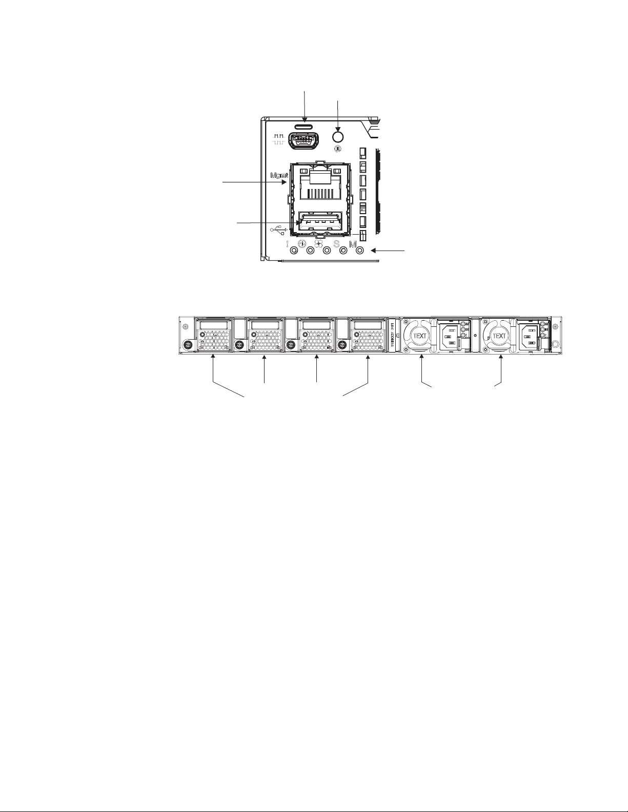
RS-232 port
Reset button
RJ-45 Mgmt port
USB port
Figure 1. IBM RackSwitch G8332 front panel detail
System status LEDs
Fan modules
Figure 2. IBM RackSwitch G8332 rear panel
Power supplies
Reset button
The Reset button is recessed within a hole on the front panel. Use a straightened
paper clip or similar object to press the Reset button. The Reset button allows
technicians to reset the switch, as follows:
v Press Reset: The switch resets and reloads the configuration files.
v Press and hold Reset for five seconds: The switch resets and configures all
settings to factory defaults.
Fans
Four internal hot-swap fan modules cool the switch unit. If an individual fan module
fails, the other fans continue to run, and the switch unit continues to operate
normally. You can replace a hot-swap fan module while the switch is operating.
Fan operation and internal temperatures are monitored. If the air temperature
exceeds a desired threshold, the environmental monitor displays warning
messages.
Note: If a fan fails, the maximum operating temperature drops from 40⁰ Cto35⁰ C
(104⁰ Fto95⁰ F).
Attention: The Service(!)LEDflashes and the Fan LED flashes if there is a
failure of one or more fan modules. The failed fan module LED (rear panel) flashes
to indicate a failure.
Chapter 1. Introduction 5
Page 22

AC power supply
The RackSwitch has two hot-swap redundant AC power supplies. The Rackswitch
uses a 550 W power supply for front-to-rear air flow and a 750 W power supply for
rear-to-front air flow. Each power supply has an individual IEC 320 C14 power
connector on the rear panel. The power cord attaches to a universal grounded AC
power source. You can replace a hot-swap power supply module without powering
off the switch or disrupting switch functions.
DANGER
Hazardous voltage, current, or energy levels are present inside any
component that has this label attached. Do not open any cover or barrier
that contains this label.
(L001)
Each power supply can be connected to a separate AC circuit to mitigate the risk of
down time during a power failure. When used in a redundant configuration, the dual
power supplies have a load-sharing capability that enables each power supply to
operate at approximately 50% of full load. Using redundant power can minimize the
power disruption during a power supply failure and extend the expected lifetime of
each power supply by operating normally in a conservative power mode.
Switch ports
There is no power switch on the RackSwitch; the switch unit powers up when
power is supplied through the power cords.
The Power Supply LED indicates the status of the power supplies. The LED flashes
when only one power cord is connected, and is steady when both power cords are
connected.
The RackSwitch switch ports and port options are described in the following
sections.
QSFP+ ports
Thirty-two 40 GbE QSFP+ ports are located on the front panel. These ports accept
supported optical QSFP+ transceivers or direct attach cables (DACs). The
supported transceivers interoperate with any 40GBASE-SR4 compliant device, and
support distances up to 100 meters on OM3 fiber. Transceivers must be purchased
separately.
The QSFP+ ports support one 40 GbE connection, or four 10 GbE connections,
using a breakout cable (on ports 2 to 25) or QSFP+ optical transceiver with
MTP-to-4 LC (SFP+) fiber breakout cable. This option supports only IBM
10GBASE-SR SFP+ transceivers. The 40GBASE-SR4 specification (802.3ba-2010)
indicates a higher optical power level than standard 10GBASE-SR. SFP+ SR
transceivers can handle the higher optical power levels.
6 IBM System Networking RackSwitch G8332: Installation Guide
Page 23
The QSFP+ connectors on supported breakout DACs are labelled A, B, C, and D,
which correspond to the first, second, third, and fourth ports in the port range.
For the available QSFP+ transceivers and DACs for the switch, see
https://www-01.ibm.com/products/hardware/configurator/americas/bhui/launchNI.wss.
RJ-45 management port
The 10/100/1000BASE-T management port (RJ-45) is located on the front panel.
These management ports support in-line management and Control Plane Stacking.
The following table describes the RJ-45 connector pin assignments.
Table 2. RJ-45 Port pin assignments
Pin number Signal Description
1 BI DA+ Bi-directional data pair A positive
2 BI DA- Bi-directional data pair A negative
3 BI DB+ Bi-directional data pair B positive
4 BI DC+ Bi-directional data pair C positive
5 BI DC- Bi-directional data pair C negative
6 BI DB- Bi-directional data pair B negative
7 BI DD+ Bi-directional data pair D positive
8 BI DD- Bi-directional data pair D negative
Console port
The RS-232 (mini-USB) serial console port is located on the front panel. The
following table describes the pinouts for the mini-USB port.
Table 3. Console port pin assignments
Pin number Function
Pin 1 No connect
Pin 2 RS232-SIN
Pin 3 RS232_SOUT
Pin 4 No connect
Pin 5 Ground
The console cable provides an RJ-45 connector. A retention clip is available to
secure the console connection.
The following table describes the pin assignments for the RJ-45 connector on the
console cable.
Table 4. RJ-45 connector pin assignments
Pin number Function
1 RTS (Request To Send)
2 DTR (Data Terminal Ready
3 TxD (Transmit Data)
4 GND (Ground)
5 GND (Ground)
Chapter 1. Introduction 7
Page 24
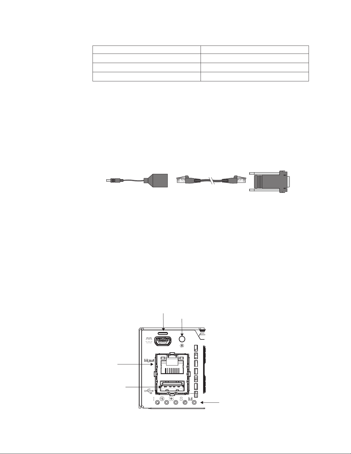
Table 4. RJ-45 connector pin assignments (continued)
Pin number Function
6 RxD (Receive Data)
7 DSR (Data Set Ready)
8 CTS (Clear To Send)
The following items are also included with the console cable.
v Category 5 patch cable
v RJ-45 to female DB9 adapter
To connect a computer or terminal to the switch, first connect the console cable to
the mini-USB port on the front panel. Connect one end of the patch cable to the
RJ-45 port on the console cable, and the other end of the patch cable to the
RJ-45-to-DB9 adapter (see the following illustration).
Switch LEDs
To
Switch
Switch
Console Cable
Figure 3. Console cable connections
Category 5
Patch Cable
RJ-45 Adapter
To P C
Terminal
USB port
The USB port enables you to connect a USB drive to the switch. You can copy files
from the switch to the USB drive, or from the USB drive to the switch. You can also
start the switch using files on the USB drive.
®
For more information about using the USB drive, see the Release Notes
switch.
One LED stack provides system status and port link status. The following illustration
shows the system LEDs.
RS-232 port
Reset button
for the
RJ-45 Mgmt port
USB port
8 IBM System Networking RackSwitch G8332: Installation Guide
System status LEDs
Page 25
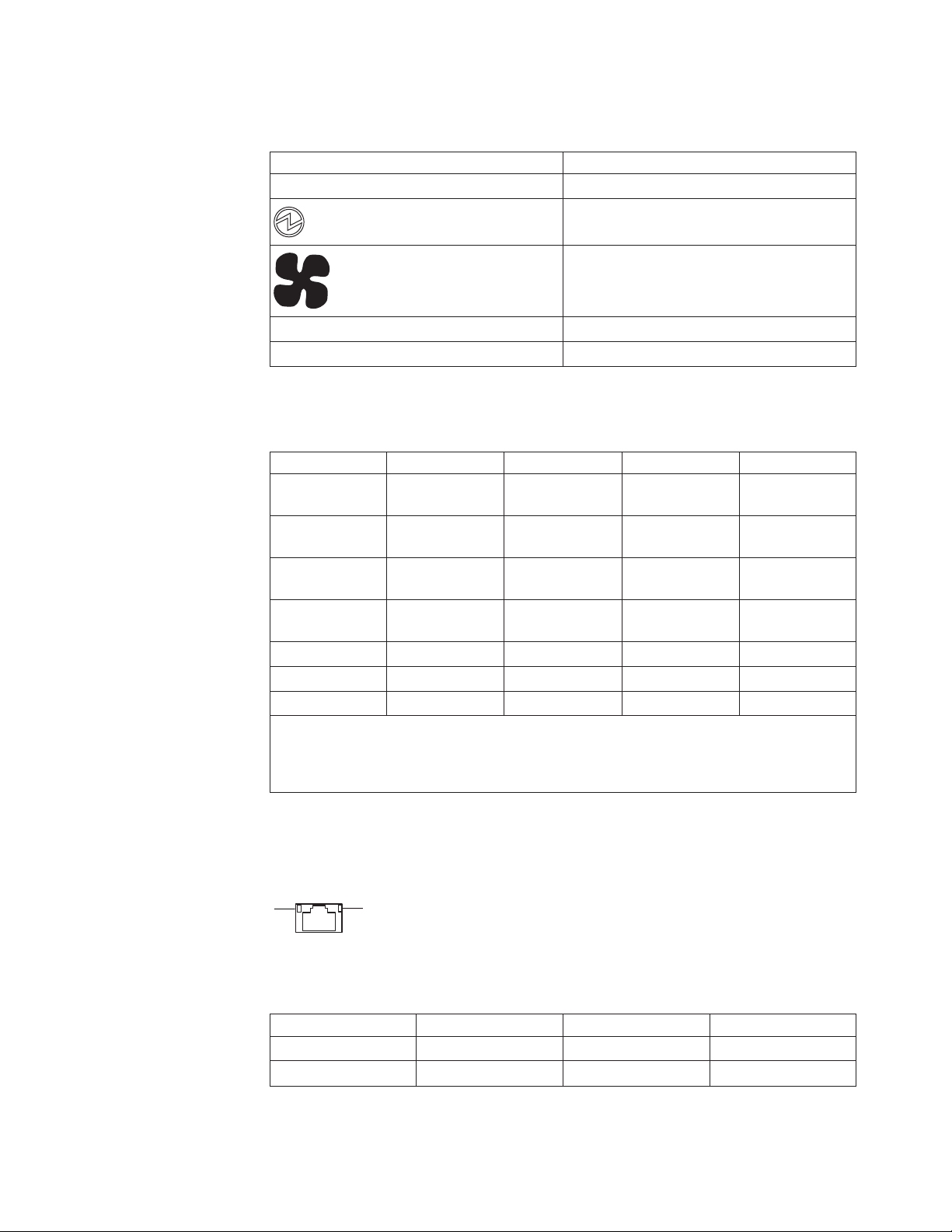
The system LEDs are described in the following table.
Table 5. System LEDs
Symbol Description
! Service indicator
Power supplies and power input status
Fans status
S Stacking indicator
M Media dependent adapter (MDA) status
The following table describes the system LEDs.
Table 6. System LED descriptions
Function Service Power supply Fans MDA
Total Power
Failure
Service Required Flash blue Flash green
Power SuppliesOKNot applicable Steady green Not applicable Not applicable
Off Off Off Off
(Note 1)
Flash green
(Note 2)
Flash green
Power Supply
Failure
Fans OK Not applicable Not applicable Steady green Not applicable
Fan Failure Flash blue Not applicable Flash green Not applicable
MDA OK Not applicable Not applicable Not applicable Steady green
Note 1: If service required is due to a power supply failure, this LED flashes. Otherwise,
it is steady green.
Note 2: If service required is due to fan failure, this LED flashes. Otherwise, it is steady
green.
Flash blue Flash green Not applicable Not applicable
RJ-45 LEDs
The RJ-45 LEDs are shown in the following illustration.
RJ-45 port LEDs
Status LEDs for the RJ-45 management port are described in the following table.
Table 7. RJ-45 LEDs status
LED Steady green Flashing green Off
Link Link up Not applicable No link
Activity Not applicable Activity No activity
Chapter 1. Introduction 9
Page 26
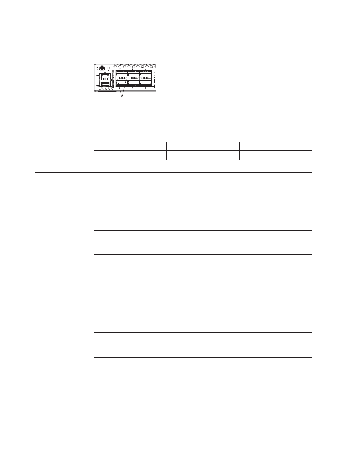
QSFP+ LEDs
The QSFP+ LEDs are shown in the following illustration.
QSFP+ LEDs
Figure 4. QSFP+ LEDs
Status LEDs for the QSFP+ ports are described in the following table.
Table 8. QSFP+ LEDs status (10 GbE mode and 40 GbE mode)
Steady green Flash green Off
Valid link Activity No Link
Technical specifications
The RackSwitch technical specifications are described in the following sections.
Physical characteristics
The physical characteristics of the RackSwitch are listed in the following table.
Table 9. Physical characteristics
Specification Physical characteristics
Dimensions (HxWxD) 4.4x43.9 x 51.3 cm.
Weight 11.5 kg. (25 lb) (maximum)
Environmental specifications
The environmental specifications for the RackSwitch are listed in the following table.
Table 10. Environmental specifications
Specification Measurement
Temperature, ambient operating 0°C to +40°C (32° to 104°F)
Temperature (fan failure), operating 0°C to +35°C (32° to 95°F)
Temperature, storage -40°C to +85°C (-40° to 185°F)
Relative humidity (non-condensing),
operating
Relative humidity (non-condensing), storage 10 to 90%
Altitude, operating 1,800 m (6,000 feet)
Altitude, storage 12,190 m (40,000 feet)
Acoustic noise Less than 65dB
Heat dissipation 920 BTU/hour (typical)
(1.73 x 17.3 x 20.2 in.)
10 to 90%
1710 BTU/hour (maximum)
10 IBM System Networking RackSwitch G8332: Installation Guide
Page 27

Power specifications
The power specifications for the RackSwitch are listed in the following table.
Table 11. AC power specifications
Specification Measurement
Number of power supplies 2 (1+1 load sharing/redundant)
AC-input frequency (universal) 50 - 60 Hz
AC-input voltage (universal) 100-240 VAC
AC inrush current 15 A
AC-input current (typical) 2.3 A (RMS) @ 120 V
AC-input current (maximum) 4.2 A (RMS) @ 120 V
Power supply rated output power 550 W each (Front-to-rear airflow)
System power dissipation (typical) 270 W
System power dissipation (maximum) 500 W
DC-output current 20 A @ 12 V (total typical)
1.2 A (RMS) @ 230 V
2.2 A (RMS) @ 230 V
750 W each (Rear-to-front airflow)
Chapter 1. Introduction 11
Page 28

12 IBM System Networking RackSwitch G8332: Installation Guide
Page 29

Chapter 2. Installing the RackSwitch and options
This chapter describes the how to install the RackSwitch chassis and the
associated RackSwitch components.
v “Installing the RackSwitch in the standard equipment rack” on page 17
v “Installing the RackSwitch in the IBM iDataPlex rack” on page 20
®
v “Installing the RackSwitch in the IBM System x
v “Installing the 1U air duct option in a rack” on page 25
v “Installing a QSFP+ transceiver” on page 28
Note: When replacing a RackSwitch chassis, all internal components must also be
removed from the chassis and replaced in the new chassis. For more
information on removing and replacing the RackSwitch and components, see
Chapter 3, “Removing and replacing the RackSwitch and components,” on
page 31.
Before installing the RackSwitch
Locate and record the important product information about the switch in the
following table. The identification labels contain the machine-type model (MTM)
number, serial number and part number (front tab, rear panel and/or bottom of the
unit), and the media access control (MAC) address (rear of unit) for the switch. The
MAC address is not required for opening a service call.
or Power rack” on page 22
You can also review and record your product serial number and other required
information through the software interface by issuing the show sys-info command
using the ISCLI interface or the /info/sys/general command using the MenuCLI
interface. For more information about these commands, see “Configuring Vital
Product Data after a switch replacement” on page 42.
After the switch is installed most of the identification labels are hidden from view
and require removing the switch in order to relocate them.
Attention: This product information is required to register your product, to update
your firmware, place a service call, and replace the RackSwitch.
Note: The following sample RackSwitch identification (ID) labels may have different
MTM and part numbers than your unit.
© Copyright IBM Corp. 2014 13
Page 30

Required tools
Figure 5. Sample RackSwitch ID labels
Record this information below and print this page and keep it in a safe place for
possible future reference. You will need this information when you register the
switch with IBM. You can register the switch at http://www.ibm.com/support/
mysupport/.
Product name IBM System Networking RackSwitch G8332
Model number _____________________________________________
Serial number _____________________________________________
Part number _____________________________________________
Media access control
(MAC) address for switch
MAC addresses for other
components
_____________________________________________
_____________________________________________
_____________________________________________
_____________________________________________
You need the following tools or equipment to install the RackSwitch:
v Standard flat-blade screwdriver
v #2 Phillips screwdriver
v Electrostatic discharge wrist strap
Package contents
The basic RackSwitch G8332 package contains the following items:
v G8332 switch unit (one of the following):
– G8332 (front-to-rear) provides front-to-rear air flow
– G8332 (rear-to-front) provides rear-to-front airflow
v One standard rack mount kit that includes:
14 IBM System Networking RackSwitch G8332: Installation Guide
Page 31

– Two brackets
– Screws to attach brackets to the switch unit
– Screws to attach the switch unit to the equipment rack
v Mini-USB to RJ-45 serial cable, category 5 patch cable, RJ-45 to DB9 adapter
v One IBM Documentation CD which includes the IBM System Networking
RackSwitch G8332 Installation Guide (this document)
v One Warranty Information document
v One Important Notices document
Environmental requirements
This section describes the basic environmental requirements for the RackSwitch.
Make sure that the location where you install the switch meets the following
requirements:
v Install the switch unit in a dry, clean, well-ventilated area.
v Provide adequate space in the front and back of the switch unit, to ensure proper
air flow.
v Make sure that an adequate grounded power supply is within reach of the switch
unit.
v Make sure that twisted-pair cable is routed away from power lines, fluorescent
lighting fixtures and other sources of electrical interference.
Preventing electric shock
This product does not contain any user-serviceable parts. Do not remove the cover
of this device.
The G8332 AC power model is designed to work with single-phase power systems
that have a grounded neutral conductor. To reduce the risk of electric shock, always
plug the power cord into a grounded power outlet.
Chapter 2. Installing the RackSwitch and options 15
Page 32

DANGER
When working on or around the system, observe the following precautions:
Electrical voltage and current from power, telephone, and communication
cables are hazardous. To avoid a shock hazard:
v Connect power to this unit only with the provided power cord. Do not
use the provided power cord for any other product.
v Do not open or service any power supply assembly.
v Do not connect or disconnect any cables or perform installation,
maintenance, or reconfiguration of this product during an electrical
storm.
v The product might be equipped with multiple power cords. To remove all
hazardous voltages, disconnect all power cords.
v Connect all power cords to a properly wired and grounded electrical
outlet. Ensure that the outlet supplies proper voltage and phase rotation
according to the system rating plate.
v Connect any equipment that will be attached to this product to properly
wired outlets.
v When possible, use one hand only to connect or disconnect signal
cables.
v Never turn on any equipment when there is evidence of fire, water, or
structural damage.
v Disconnect the attached power cords, telecommunications systems,
networks, and modems before you open the device covers, unless
instructed otherwise in the installation and configuration procedures.
v Connect and disconnect cables as described in the following procedures
when installing, moving, or opening covers on this product or attached
devices.
To disconnect:
1. Turn off everything (unless instructed otherwise).
2. Remove the power cords from the outlets.
3. Remove the signal cables from the connectors.
4. Remove all cables from the devices.
To connect:
1. Turn off everything (unless instructed otherwise).
2. Attach all cables to the devices.
3. Attach the signal cables to the connectors.
4. Attach the power cords to the outlets.
5. Turn on the devices.
(D005)
16 IBM System Networking RackSwitch G8332: Installation Guide
Page 33

Handling static-sensitive devices
Attention: Static electricity can damage the switch and other electronic devices.
To avoid damage, keep static-sensitive devices in their static-protective packages
until you are ready to install them.
To reduce the possibility of electrostatic discharge, observe the following
precautions:
v Limit your movement. Movement can cause static electricity to build up around
you.
v The use of a grounding system is recommended. For example, wear an
electrostatic-discharge wrist strap, if one is available.
v Handle the device carefully, holding it by its edges or its frame.
v Do not touch solder joints, pins, or exposed printed circuitry.
v Do not leave the device where others can handle and damage it.
v While the device is still in its static-protective package, touch it to an unpainted
metal part of any unpainted metal surface on a grounded rack component in the
rack in which you are installing the device, for at least 2 seconds. This drains
static electricity from the package and from your body.
v Remove the device from its package and install it directly into the switch without
setting it down. If it is necessary to set down the device, put it back into its
static-protective package. Do not place the device on a switch cover or on a
metal surface.
v Take additional care when you handle devices during cold weather. Heating
reduces indoor humidity and increases static electricity.
Installing the RackSwitch in the standard equipment rack
This section describes how to install the RackSwitch in the standard 19-inch
equipment rack. For information about mounting the RackSwitch in other rack types,
see the following sections:
v “Installing the RackSwitch in the IBM iDataPlex rack” on page 20
®
v “Installing the RackSwitch in the IBM System x
The following parts come in the standard mounting kit.
Table 12. 2-post rack mount kit parts
Item number Description Quantity
1 M6 locking washers 4
2 M6 screws 4
3 M6 clip nuts 4
4 M6 cage nuts 4
5 M4 screws 8
6 Mounting bracket 2
Attention: The rack-mounting frame may not be able to support the weight of the
networking switch with only the front post mounting brackets (2-post application). If
the switch has an undesirable amount of sag, it is recommended to use a 4-post
mounting kit.
or Power rack” on page 22
Attention: For earthquake stability, mount the switch in a 4-post rack.
Chapter 2. Installing the RackSwitch and options 17
Page 34

DANGER
Rack-mounted devices are not to be used as shelves or work spaces.
(L002)
Attention: For earthquake stability, mount the switch in a 4-post rack.
To install the RackSwitch in a standard 19-inch equipment rack, complete the
following steps:
1. Locate and record the product switch information to configure and register your
product and set aside. See “Before installing the RackSwitch” on page 13.
Note: If this switch is a replacement switch, copy the product information from
the original switch onto the RID label that is shipped with replacement
switch and affix the new label to the bottom of the new switch.
2. Use the M4 screws to attach a mounting bracket to each side of the switch.
Torque the screws to approximately 2.0 newton-meters (Nm) +/- 0.1 Nm (17.7
inch-pounds).
3. Gently slide the switch into the rack.
4. Use the M6 screws, washers, and clip nuts (or cage nuts) to secure the switch
unit to the rack. Torque the screws to approximately 5.7 Nm +/- 0.1 Nm (50
inch-pounds).
18 IBM System Networking RackSwitch G8332: Installation Guide
6
5
Page 35

3
2
1
5. Connect all cables.
6. Initialize the switch, see Chapter 4, “Initializing the RackSwitch,” on page 45.
Attention: If this is a switch replacement, make sure the VPD is updated to
avoid losing the licensed electronic entitlement data of the RackSwitch. For
more information, see “Configuring Vital Product Data after a switch
replacement” on page 42.
Chapter 2. Installing the RackSwitch and options 19
Page 36

Installing the RackSwitch in the IBM iDataPlex rack
This section describes how to install the RackSwitch in an IBM iDataPlex rack. The
iDataPlex mounting kit allows the switch to be mounted either vertically or
horizontally. For information about mounting the RackSwitch in other rack types,
see the following sections:
v “Installing the RackSwitch in the standard equipment rack” on page 17
®
v “Installing the RackSwitch in the IBM System x
The iDataPlex rack mount kit must be purchased separately. The following table
lists the parts included in the iDataPlex mounting kit.
Table 13. iDataPlex rack mount kit parts
Item number Description Quantity
1 Label 1
2 M6 locking washers 8
3 M6 screws 8
4 M6 clip nuts 8
5 M4 screws 16
6 Switch front bracket 2
7 Switch rear bracket 2
8 Rear mounting bracket 2
or Power rack” on page 22
DANGER
Rack-mounted devices are not to be used as shelves or work spaces.
(L002)
To install the RackSwitch in an iDataPlex rack, complete the following steps:
1. Locate and record the product switch information to configure and register your
product and set aside. See “Before installing the RackSwitch” on page 13.
Note: If this switch is a replacement switch, copy the product information from
the original switch onto the RID label that is shipped with replacement
switch and affix the new label to the bottom of the new switch.
2. Use the M4 screws to attach front and rear mounting brackets to each side of
the switch unit. Torque the screws to approximately 2.0 newton-meters (Nm) +/-
0.1 Nm (17.7 inch-pounds).
20 IBM System Networking RackSwitch G8332: Installation Guide
Page 37

7
1
6
5
3. Slide the RackSwitch into the rack.
4. Use the M6 washers and screws are used to mount the switch unit into the
rack. Torque the screws to approximately 5.7 Nm +/- 0.1 Nm (50 inch-pounds).
4
2
3
5. Use the M6 washers, screws, and clip nuts are used to attach the alignment
plate. Torque the screws to approximately 5.7 Nm +/- 0.1 Nm (50 inch-pounds).
4
2
3
8
10
Chapter 2. Installing the RackSwitch and options 21
Page 38

6. Connect all cables.
7. Initialize the switch, see Chapter 4, “Initializing the RackSwitch,” on page 45.
Attention: If this is a switch replacement, make sure the VPD is updated to
avoid losing the licensed electronic entitlement data of the RackSwitch. For
more information, see “Configuring Vital Product Data after a switch
replacement” on page 42.
Installing the RackSwitch in the IBM System x®or Power rack
This section provides how to install the RackSwitch in an IBM System Networking
Adjustable 19” 4-post rail kit (for Power and System x racks). For information about
mounting the RackSwitch in other rack types, see the following sections:
v “Installing the RackSwitch in the standard equipment rack” on page 17
v “Installing the RackSwitch in the IBM iDataPlex rack” on page 20
The IBM System Networking adjustable 19” 4-post rail mount kit parts must be
purchased separately.
The following table lists the parts included in the IBM System Networking adjustable
19” 4-post rail mounting kit.
Table 14. IBM System Networking adjustable 19” 4-post rail mount kit parts
Item number Description Quantity
1 Label 1
2 M6 locking washers 8
3 M3 screws 4
4 M6 screws 8
5 M6 clip nuts 8
6 M6 cage nuts 8
7 M4 screws 16
8 Filler plate 1
9 Switch front bracket 2
10 Rear mounting bracket 1
11 Rear mounting bracket with
cord exit
1
DANGER
Rack-mounted devices are not to be used as shelves or work spaces.
(L002)
22 IBM System Networking RackSwitch G8332: Installation Guide
Page 39

To install the RackSwitch in the IBM System Networking adjustable 19” 4-post rack
(for Power and System x racks), complete the following steps:
1. Locate and record the product switch information to configure and register your
product and set aside. See “Before installing the RackSwitch” on page 13.
Note: If this switch is a replacement switch, copy the product information from
the original switch onto the RID label that is shipped with replacement
switch and affix the new label to the bottom of the new switch.
2. Use the M4 screws to attach the front mounting brackets to each side of the
switch. Torque the screws to approximately 2.0 newton-meters (Nm) +/- 0.1 Nm
(17.7 inch-pounds).
9
9
1
7
3. Use the M6 screws, washers, and clip nuts are used to connect the front
mounting brackets to the front and rear posts in the rack. Torque the screws to
approximately 5.7 Nm +/- 0.1 Nm (50 inch-pounds).
Chapter 2. Installing the RackSwitch and options 23
Page 40

6
4
2
4. Slide the rear mounting brackets into the slots available on the front mounting
brackets.
SEE STEP 5
10
11
5. Use the M6 washers, screws, and clip nuts to attach the filler plate to the rear
mounting brackets. Torque the screws to approximately 5.7 Nm +/- 0.1 Nm (50
inch-pounds). If required, insert the filler plate as shown.
24 IBM System Networking RackSwitch G8332: Installation Guide
Page 41

8
4
2
6
6. Use the M3.5 screws to secure the rear brackets to the front brackets. Torque
the screws to approximately 1.1 Nm +/- 0.1 Nm (10 inch-pounds).
9
3
10 11
7. Connect all the cables.
8. Initialize the switch, see Chapter 4, “Initializing the RackSwitch,” on page 45.
Attention: If this is a switch replacement, make sure the VPD is updated to
avoid losing the licensed electronic entitlement data of the RackSwitch. For
more information, see “Configuring Vital Product Data after a switch
replacement” on page 42.
Installing the 1U air duct option in a rack
The RackSwitch supports an optional 1U air duct to maximize air flow conditions in
a 19" rack. For 1U air duct option part numbers, see the Chapter 6, “Replaceable
switch parts,” on page 51 section.
Mounting kit components
The 1U air duct option ships with:
v One 1U air duct unit
v One 1U air duct mechanical assembly mounting kit
v One power cord
Chapter 2. Installing the RackSwitch and options 25
Page 42

7
1
The following table lists the parts included with the 1U air duct mounting kit.
Table 15. 1U air duct mechanical assembly mounting kit
Item number Description Quantity
1 Cable tie 4
2 1U Duct sleeve (short) 1
3 Mounting bracket, right,
assembly, 1U duct
4 Mounting bracket, left,
assembly, 1U duct
5 Foam carrier assembly,
includes half shears and
foam carrier
7 Screw, slotted, M3.5, 7 mm,
flanged hex head
1
1
2
6
DANGER
Rack-mounted devices are not to be used as shelves or work spaces.
(L002)
26 IBM System Networking RackSwitch G8332: Installation Guide
Page 43

To install the 1U air duct option in a 19" rack, complete the following steps.
1. Loosen and remove the mounting screws from the both sides of the mounting
rail and set aside to reuse to secure the foam carrier.
Foam carrier snug against rear of unit
Reuse mounting screws
Half shear
Mounting screws
2. Place the half shears on the rear side of the foam carriers and use the M3.5
mounting rail screws to secure the foam carrier assemblies snugly against the
rear of the RackSwitch unit. Torque the screws to approximately 1.1 Nm (10
inch-pounds).
Note: There are additional M3.5 screws in the air duct assembly kit.
3. Plug the power cords into their respective RackSwitch power cord connectors
and using the tie wraps, secure the power cords to the mounting rails.
Power connection
Tie wraps
Power connection
Tie wraps
4. Use the M6 screws to secure the air duct brackets to the mounting rails. Torque
the screws to approximately 5.7 Nm +/- 0.1 Nm (50 inch-pounds).
Chapter 2. Installing the RackSwitch and options 27
Page 44

Air duct mounting bracket
M6 screws
M3.5 screws
5. Use the M3.5 screws to secure the air duct mounting bracket to the rack
chassis. Torque the screws to approximately 1.1 Nm +/- 0.1 Nm (10
inch-pounds).
6. Gently slide the air duct unit side flanges into the card guides until the unit is
seated firmly. Make sure that the foam strip is oriented on top.
7. Use the two M4 thumbscrews to secure the air duct unit to the air duct brackets.
For information about removing the air duct, see “Removing the 1U air duct option”
on page 41.
Installing a QSFP+ transceiver
The RackSwitch G8332 supports QSFP+ fiber transceivers. For the available
transceivers for the switch, see https://www-01.ibm.com/products/hardware/
configurator/americas/bhui/launchNI.wss.
The QSFP+ ports accept approved QSFP+ transceivers. The QSFP+ optical
transceiver provides an MTP cable connector for connecting to external ports.
Card guides
Side flanges
Foam
M4
thumbscrews
28 IBM System Networking RackSwitch G8332: Installation Guide
Page 45

CAUTION:
This product might contain one or more of the following devices: CD-ROM
drive, DVD-ROM drive, DVD-RAM drive, or laser module, which are Class 1
laser products. Note the following information:
v Do not remove the covers. Removing the covers of the laser product could
result in exposure to hazardous laser radiation. There are no serviceable
parts inside the device.
v Use of the controls or adjustments or performance of procedures other
than those specified herein might result in hazardous radiation exposure.
(C026)
CAUTION:
This product contains a Class 1M laser. Do not view directly with optical
instruments. (C028)
To install a QSFP+ optical transceiver in a QSFP+ port, complete the following
steps.
Note: To avoid damage to the cable or the SFP transceiver, do not connect the
cable before you install the transceiver.
1. Remove the safety cap and pull the locking lever into the down (unlocked)
position.
2. Insert the transceiver into the port until it clicks into place. Use minimal pressure
when you insert the transceiver into the slot. Do not use excessive force when
you insert the transceiver; you can damage the transceiver or the QSFP+ slot.
The transceiver has a mechanical guide key to prevent you from inserting the
transceiver incorrectly.
3. Pull up the locking lever to lock the transceiver into place.
4. Connect the fiber-optic cable.
To remove a QSFP+ optical transceiver, disconnect the fiber-optic cable, and
pull down the locking lever to release the transceiver. After you remove the
transceiver, replace the safety cap.
Chapter 2. Installing the RackSwitch and options 29
Page 46

30 IBM System Networking RackSwitch G8332: Installation Guide
Page 47

Chapter 3. Removing and replacing the RackSwitch and components
This chapter describes the how to remove and replace the RackSwitch chassis and
the associated RackSwitch components, such as, a fan module. When replacing a
RackSwitch chassis, all internal components must also be removed from the
chassis and replaced in the new chassis.
For more information to remove and replace individual components, see the
following sections.
v “Removing and replacing the RackSwitch chassis unit from a rack”
v “Removing and replacing the AC power supply module” on page 36
v “Removing and replacing the fan module” on page 37
v “Removing and replacing the QSFP+ media dependent adapter module” on page
39
v “Removing the 1U air duct option” on page 41
v “Removing and replacing the main RackSwitch chassis unit” on page 41
Removing and replacing the RackSwitch chassis unit from a rack
This section describes how to remove the RackSwitch chassis unit from supported
equipment racks. For information about removing the RackSwitch from different
racks, see the following sections:
v “Removing the RackSwitch chassis from a standard equipment rack”
v “Removing the RackSwitch from a System x or Power rack” on page 34
v “Removing the RackSwitch from an iDataPlex rack” on page 32
Removing the RackSwitch chassis from a standard equipment rack
To remove the RackSwitch from a standard equipment rack, complete the following
steps:
1. Disconnect all cables.
2. Loosen and remove M6 screws, washers, and clip nuts (or cage nuts) to
remove the switch unit from the rack.
© Copyright IBM Corp. 2014 31
Page 48

3
2
1
3. Slide the switch out of the rack.
4. Loosen and remove the M4 screws attaching the mounting bracket on each side
of the switch.
6
Removing the RackSwitch from an iDataPlex rack
To remove the RackSwitch from an iDataPlex rack, complete the following steps:
1. Disconnect all cables.
2. Loosen and remove the M6 washers, screws, and clip nuts that attach the
alignment plate.
32 IBM System Networking RackSwitch G8332: Installation Guide
5
Page 49

4
2
3
8
10
3. Loosen and remove the M6 washers and screws that mount the switch unit into
the rack.
4
2
3
4. Slide the RackSwitch out of the rack.
5. Loosen and remove the M4 screws that attach front and rear mounting brackets
to each side of the switch unit.
1
6
Chapter 3. Removing and replacing the RackSwitch and components 33
5
7
Page 50

Removing the RackSwitch from a System x or Power rack
To remove the RackSwitch from a System x or Power rack, complete the following
steps:
1. Disconnect all cables.
2. Loosen and remove M3 screws that secure the rear brackets to the front
brackets.
9
3
10 11
3. Loosen and remove M6 washers, screws, and clip nuts that attach the filler
plate (if present) to the rear mounting brackets.
8
4
4. Slide the rear mounting brackets out of the slots available on the front mounting
brackets.
34 IBM System Networking RackSwitch G8332: Installation Guide
6
2
Page 51

SEE STEP 5
10
11
5. Loosen and remove the M6 screws, washers, and clip nuts are used to connect
the front mounting brackets to the front and rear posts in the rack.
6
4
2
6. Slide the RackSwitch out of the rack.
7. Loosen and remove the M4 screws that attach the front mounting brackets to
each side of the switch.
Chapter 3. Removing and replacing the RackSwitch and components 35
Page 52

9
Removing and replacing the AC power supply module
The RackSwitch operates with either one or two active AC power supply modules.
You can replace a hot-swap power supply module without powering off the switch or
disrupting switch functions.
Each AC power supply module has a power cord for connection to an AC power
outlet.
9
1
7
Each power supply module has three LEDs that are visible from the rear panel. The
following table describes the LEDs.
Table 16. Power supply module LEDs
LED status Description
OK
Green DC output power is present.
Off DC output power is OK.
Service(!)
Amber Power supply or fan module failure.
Off Power supply and fan modules are
~ AC Input
Green AC power is OK.
Off No power. Output is disabled, or input power
Removing the AC power supply module
To remove the AC power supply module, complete the following steps:
1. Remove the power cord from the power connector.
2. Press the release latch on the left side of the power supply module, and slide
the module out of the slot.
operational.
is out of operating range.
36 IBM System Networking RackSwitch G8332: Installation Guide
Page 53

Attention: Do not leave the power-supply slot empty for more than 90
seconds while the switch is operating.
Replacing the AC power supply module
DANGER
Multiple power cords. The product might be equipped with multiple power
cords. To remove all hazardous voltages, disconnect all power cords.
(L003)
To replace the AC power supply module, complete the following steps:
1. Insert the power supply module into the power-supply slot, and gently push it
into the slot until it latches. Each power supply module has a mechanical guide
key to prevent you from inserting the module incorrectly.
2. Connect the power cord to the power supply module and to an AC power
source.
3. Turn on the power at the power source.
4. Make sure that the power supply OK and AC LEDs are green.
Removing and replacing the fan module
The RackSwitch contains four hot-swap fan modules. All four fan modules are
required for normal operation.
Chapter 3. Removing and replacing the RackSwitch and components 37
Page 54

The switch continues to operate when there is one failed fan module. If one fan
module fails, the switch sends an error message. If a second fan module fails, the
switch sends an error message, writes a failure log to flash memory, and shuts
down.
Each fan module has a green LED that is visible from the rear panel. The LED
shows the status of the fan module, as follows:
Table 17. Fan LED states
LED state Description
Lit Fans are operational.
Off Fan unit has no power.
Flashes Fan speed has failed. Replace the fan
Removing the fan module
To remove the fan module, complete the following steps:
1. Loosen the retainer screw.
2. Grasp the extractor handle and gently pull the fan module from the slot.
module.
Thumbscrew
Attention: If inlet air temperature exceeds 35⁰ C (95⁰ F), replace the fan
module within 5 minutes to avoid overheating the switch.
Replacing the fan module
To replace a fan module, complete the following steps:
1. Loosen the retainer screws and slide the failed fan module out of the slot.
2. Remove the fan module from the antistatic shielded bag.
3. Slide the fan module into the open slot and gently push it all the way into the
slot, so that it firmly engages with the connector (see the illustration). Each fan
module has a mechanical guide key to prevent you from inserting the module
incorrectly.
38 IBM System Networking RackSwitch G8332: Installation Guide
Page 55

Thumbscrew
4. Tighten the retaining screw on the fan module. Torque the screw to
approximately 0.2 Nm (1 inch-pounds).
Removing and replacing the QSFP+ media dependent adapter module
The QSFP+ MDA module provides eight 40 GbE ports to expand the number of
RackSwitch QSFP+ ports to thirty-two ports.
There is one MDA module slot on the front panel of the RackSwitch. See Table 5 on
page 9 for more information about the MDA status LED.
The RackSwitch will not successfully boot without the QSFP+ MDA module
installed. If the QSFP+ MDA module port is empty during a power on or during a
hardware reset, the system will halt with an error message.
Note: Replace the MDA module and press Enter to clear the error and reboot the
switch.
Removing the MDA module
You must turn off the power to the MDA module before you remove it from the
RackSwitch. To remove the MDA module, complete the following steps.
1. Log into the system to turn off the power to the MDA module and use one of the
following commands:
v From the IBM-NOS prompt, enter:
ibm-nos: /oper/mda d
Where d is disable
v From the ISCLI prompt, enter:
iscli: mda shutdown
2. Gently pull the MDA lock handle to unlock the MDA module from the
RackSwitch chassis, and slide the module out of the MDA slot.
Chapter 3. Removing and replacing the RackSwitch and components 39
Page 56

MDA lock handle
Replacing the MDA module
To replace the MDA module, complete the following steps.
1. Pull the MDA lock handle in the open position, and slide the module into the
MDA slot.
Pull to open and push to close lock handle
Pull to open and push to close lock handle
MDA lock handle
2. Push the lock handle to secure the module in place.
3. Turn on the power to the MDA module using the software commands:
From the IBM-NOS prompt, enter:
ibm-nos: /oper/mda e
Where e is enable
From the ISCLI prompt, enter:
iscli: no mda shutdown
40 IBM System Networking RackSwitch G8332: Installation Guide
Page 57

Removing the 1U air duct option
To remove the 1U air duct option from a 19" rack, complete the following steps.
1. Loosen the two M4 thumbscrews securing the air duct unit to the air duct
brackets.
M4
thumbscrews
2. Slide the air duct unit out of the rack.
To return the component to customer service for replacement, see Appendix A,
“Getting help and technical assistance,” on page 57, to help you gather all the
required information that is necessary to return a component. After you remove the
component, securely pack the component for shipping.
For instructions to replace the air duct, see “Installing the 1U air duct option in a
rack” on page 25.
Removing and replacing the main RackSwitch chassis unit
When replacing a RackSwitch chassis unit, all internal component must also be
removed from the chassis and replaced in the new chassis. The RackSwitch
operates with one or two active power supplies, three to four fan modules, and an
optional air duct unit.
When you remove a RackSwitch unit from the rack, record the product MTM
number and serial number to use for the replacement switch, see “Before installing
the RackSwitch” on page 13 to locate the product information labels on the switch
chassis or “Configuring Vital Product Data after a switch replacement” on page 42
to use an interface to display the product information for the RackSwitch.
Before you replace the RackSwitch chassis, you must remove and replace the
separate components. For more information about removing and replacing
RackSwitch components, see the following sections:
v “Removing and replacing the AC power supply module” on page 36
v “Removing and replacing the fan module” on page 37
Chapter 3. Removing and replacing the RackSwitch and components 41
Page 58

To return the chassis to customer service for replacement, see Appendix A, “Getting
help and technical assistance,” on page 57, to help you gather all the required
information that is necessary to return a component. After you remove the chassis
unit, securely pack the RackSwitch unit for shipping.
To replace the RackSwitch chassis in the rack, see the following procedures and
perform them in the order in which they are listed.
v “Replacing the AC power supply module” on page 37
v “Replacing the fan module” on page 38
v Chapter 2, “Installing the RackSwitch and options,” on page 13
Configuring Vital Product Data after a switch replacement
After you replace a RackSwitch, you must update the new switch with the VPD of
the RackSwitch being removed to avoid losing the licensed electronic entitlement
data of the RackSwitch. The VPD includes the model and serial number of the
switch. For more information on locating the VPD, see “Before installing the
RackSwitch” on page 13.
To update the VPD on a new switch, complete the following steps.
1. Log in to the switch and in the CLI mode, type
RS G8332>ibmnos
2. At the Password prompt, enter the switch password, and press Enter. The
default password is admin.
3. In the main menu, enter the MTM number for the replacement switch. For
example:
/boot/mtm 8036-AFX
where 8036-AFX is the MTM of the unit that is being replaced
4. Enter the serial number for the replacement switch. For example:
/boot/esn 1000001
where 1000001 is the serial number of the unit that is being replaced.
5. Reset the switch using the following command:
/boot/reset
6. When prompted to confirm the reset, enter y. The switch reboots.
7. After the switch reboots, at the command prompt, verify that the VPD
information is correct by issuing the show sys-info command using the ISCLI
interface or the /info/sys/general command using MenuCLI interface.
ISCLI interface output example:
show sys-info
42 IBM System Networking RackSwitch G8332: Installation Guide
Page 59

System Information at 8:26:10 Mon Jan 20, 2014
Time zone: No timezone configured
Daylight Savings Time Status: Disabled
IBM Networking Operating System RackSwitch G8332
Switch has been up for 0 days, 0 hours, 9 minutes and 43 seconds.
Last boot: 8:18:29 Mon Jan 30, 2000 (reset from console)
MAC address: a8:97:dc:8b:07:00 IP (If 1) address: 192.168.49.50
Management Port MAC Address: a8:97:dc:8b:07:fe
Management Port IP Address (if 128): 10.100.21.101
Hardware Revision: 0
Hardware Part No: BAC-00095-00
Switch Serial No: Y019CM3CE235
Manufacturing date: 13/49
Software Version 7.7.12.26 (FLASH image2), active configuration.
Boot kernel version 7.7.12.21
Temperature CPU Local : 33 C
Temperature Rear In/Ex : 30 C
Temperature Front In/Ex : 25 C
Temperature Hot Spot : 32 C
Temperature Asic Max : 38 C
Temperature MDA : 32 C
System Warning at 85 C / Shutdown at 95 C
Fan 1 Module 1: 6826rpm 60pwm(23% bias:0) Front-To-Back
Fan 2 Module 1: 6922rpm 60pwm(23% bias:0) Front-To-Back
Fan 3 Module 2: 6687rpm 60pwm(23% bias:0) Front-To-Back
Fan 4 Module 2: 7072rpm 60pwm(23% bias:0) Front-To-Back
Fan 5 Module 3: 6733rpm 60pwm(23% bias:0) Front-To-Back
Fan 6 Module 3: 6971rpm 60pwm(23% bias:0) Front-To-Back
Fan 7 Module 4: 6826rpm 60pwm(23% bias:0) Front-To-Back
Fan 8 Module 4: 7228rpm 60pwm(23% bias:0) Front-To-Back
System Fan Airflow: Front-To-Back
Power Supply 1: Front-To-Back []
Power Supply 2: Front-To-Back [94Y8104 ]
MDA CurrType=8x40GbE BootType=8x40GbE LastEvent=StartUp CurrState=Active
MDA CPLD Firmware=0.4
Or
MenuCLI interface output example:
/info/sys/general
Chapter 3. Removing and replacing the RackSwitch and components 43
Page 60

System Information at 8:23:02 Mon Jan 20, 2014
Time zone: No timezone configured
Daylight Savings Time Status: Disabled
IBM Networking Operating System RackSwitch G8332
Switch has been up for 0 days, 0 hours, 6 minutes and 35 seconds.
Last boot: 8:18:29 Mon Jan 30, 2000 (reset from console)
MAC address: a8:97:dc:8b:07:00 IP (If 1) address: 192.168.49.50
Management Port MAC Address: a8:97:dc:8b:07:fe
Management Port IP Address (if 128): 10.100.21.101
Hardware Revision: 0
Hardware Part No: BAC-00095-00
Switch Serial No: Y019CM3CE235
Manufacturing date: 13/49
Software Version 7.7.12.26 (FLASH image2), active configuration.
Boot kernel version 7.7.12.21
Temperature CPU Local : 33 C
Temperature Rear In/Ex : 30 C
Temperature Front In/Ex : 25 C
Temperature Hot Spot : 32 C
Temperature Asic Max : 37 C
Temperature MDA : 32 C
System Warning at 85 C / Shutdown at 95 C
Fan 1 Module 1: 6826rpm 60pwm(23% bias:0) Front-To-Back
Fan 2 Module 1: 6874rpm 60pwm(23% bias:0) Front-To-Back
Fan 3 Module 2: 6687rpm 60pwm(23% bias:0) Front-To-Back
Fan 4 Module 2: 7021rpm 60pwm(23% bias:0) Front-To-Back
Fan 5 Module 3: 6733rpm 60pwm(23% bias:0) Front-To-Back
Fan 6 Module 3: 7021rpm 60pwm(23% bias:0) Front-To-Back
Fan 7 Module 4: 6874rpm 60pwm(23% bias:0) Front-To-Back
Fan 8 Module 4: 7228rpm 60pwm(23% bias:0) Front-To-Back
System Fan Airflow: Front-To-Back
Power Supply 1: Front-To-Back []
Power Supply 2: Front-To-Back [94Y8104 ]
MDA CurrType=8x40GbE BootType=8x40GbE LastEvent=StartUp CurrState=Active
MDA CPLD Firmware=0.4
For more information about using the switch interface, see the Configuration
guide for your interface.
44 IBM System Networking RackSwitch G8332: Installation Guide
Page 61

Chapter 4. Initializing the RackSwitch
When you supply power to the RackSwitch, the switch initializes automatically.
DANGER
Multiple power cords. The product might be equipped with multiple power
cords. To remove all hazardous voltages, disconnect all power cords.
(L003)
or
1
2
!
1
2
The following LEDs indicate the overall system status:
v Power Supply: Steady green if both power cords are connected, flashing green if
only one power cord is connected.
v Service(!):Offifthesystem is OK, flashing if service is required.
Use the mini-USB console cable to connect the RS-232 serial port on the switch
unit front panel to a terminal or a computer running a terminal emulation program.
You can access the command-line interface to perform initial configuration tasks.
To access the switch CLI and perform initial configuration tasks, use one of the
following methods:
© Copyright IBM Corp. 2014 45
Page 62

v Connect an Ethernet cable to the RJ-45 management port and use Telnet,
SNMP, or a Web browser to access the CLI through the IP address provided by
the network’s DHCP server.
v Connect the mini-USB console cable to the RS-232 serial port on the switch
unit’s front panel, and use a terminal or a computer running a terminal emulation
program to access the switch CLI.
The console port terminal-emulation requirements are as follows:
v Default baud rate = 9,600 bps
v Character size = 8 characters
v Parity = none
v Stop bits = 1
v Data bits = 8
v Flow control = none
The switch performs initial self tests, and displays the password prompt, similar to
the following screen:
Memory Test ................................
Production Mode
PPCBoot 0.0.0.10 (new flash)
Memory Test (0x00) .............................PASSED
...
IBM System Networking RS 8332
Jan 1 00:01:27 2011:
NOTICE-5:Interface Oper Status Indication - Port 7 State UP
Password:
At the Password prompt, enter the switch password, and press Enter. The default
password is admin.
Default configuration
The switch software contains default factory-loaded configuration files. The default
configuration is part of the software; it cannot be deleted or changed. The default
settings allow the switch to perform basic functions with minimal effort by the
system administrator. DHCP is enabled by default on the management interfaces
and BOOTP is enabled by default on interface 1. If there is no DHCP offer received,
the device uses the default Mgmt _IP address (192.168.50.50/24). This address is
overwritten when a DHCP/BOOTP address is received for that interface. If
DHCP/BOOTP is enabled and there is no static address configured for
DHCP/BOOTP requests will continue to be sent. This feature does not change
existing DHCP/BOOTP functionality. See the following initial configuration example:
46 IBM System Networking RackSwitch G8332: Installation Guide
Page 63

RS G8332# show inter ip
Interface information:
1: IP4 192.168.49.50 255.255.255.0 192.168.49.255, vlan 1, up
128: IP4 192.168.50.50 255.255.255.0 192.168.50.255, vlan 4095, up
! interface ip 1
! addr <default>
! enable
!
! interface ip 128
! addr <default>
! enable
RS G8332(config)# system dhcp?
mgt dhcp on mgt port
RS G8332(config)# system dhcp mgt
Warning: Enabling dhcp will overwrite IP interface 128 and IP gateway 4 configurations.
RS G8332# show inter ip
Interface information:
1: IP4 192.168.49.50 255.255.255.0 192.168.49.255, vlan 1, up
128: IP4 192.168.50.50 255.255.255.0 192.168.50.255, vlan 4095, up
Configuring the IP interface
To manage the switch using Telnet, SNMP, or a Web browser, you must have an IP
interface. Use DHCP (enabled by default) or manually configure the following IP
parameters:
v IP address
v Subnet mask
v Gateway address
1. Log on to the switch.
2. Enter IP interface mode.
RS G8332> enable
RS G8332# configure terminal
RS G8332 (config)# interface ip 1
3. Configure an IP interface, subnet mask, and VLAN assignment. Enable the
interface.
RS G8332 (config-ip-if)# ip address 10.10.10.2 (example IP address)
RS G8332 (config-ip-if)# ip netmask 255.255.255.0
RS G8332 (config-ip-if)# vlan 1
RS G8332 (config-ip-if)# enable
RS G8332 (config-ip-if)# exit
4. Configure the default gateway. Enable the gateway.
RS G8332 (config)# ip gateway 1 address 10.10.10.1 (example gateway address)
RS G8332 (config)# ip gateway 1 enable
After you configure the IP address for your switch and you have an existing
network connection, you can use the Telnet program from an external
management station to access and control the switch. The management station
and your switch must be on the same IP subnet.
The switch module supports a command-line interface (CLI) that you can use to
configure and control the switch over the network using the Telnet program. You
can use the CLI to perform many basic network management functions. In
addition, you can configure the switch for management using an SNMP-based
network management system or a Web browser.
Chapter 4. Initializing the RackSwitch 47
Page 64

For more information about using the CLI, see the Command Reference guide
for your switch.
Using the Boot Management menu
The Boot Management menu enables you to switch the software image, reset the
switch to factory defaults, or to recover from a failed software download.
You can interrupt the boot process and enter the Boot Management menu from the
serial console port. When the system displays Memory Test, press Shift+B. The
Boot Management menu is displayed.
Resetting the System ...
Memory Test ................................
Boot Management Menu
1 - Change booting image
2 - Change configuration block
3 - Xmodem download
4 - Exit
Please choose your menu option: 1
Current boot image is 1. Enter image to boot: 1 or 2: 2
Booting from image 2
The Boot Management menu allows you to perform the following actions:
v To change the boot image, press 1 and follow the screen prompts.
v To change the configuration block, press 2, and follow the screen prompts.
v To perform an Xmodem download, press 3 and follow the screen prompts.
v To exit the Boot Management menu, press 4. The boot process continues.
Updating firmware
If firmware updates are available, you can download them from
http://www.ibm.com/supportportal/. The switch might have features that are not
described in the documentation that comes with the switch, and the documentation
might be updated occasionally to include information about those features, or
technical updates might be available to provide additional information that is not
included in the switch documentation.
Configuration settings are lost during a firmware update. Before updating the
firmware, save a copy of the configuration on a separate device. In the event of a
failed update, the saved configuration can be restored. For more information about
the configuration file, see the Application guide and Command Reference for the
switch.
Attention: Installing the wrong firmware update might cause the network switch to
malfunction. Before you install a firmware, review the readme and change history
files that are provided with the downloaded update. These files contain important
information about the update and the procedure for installing the update, including
any special procedure for updating from an early firmware version to the latest
version.
To check for firmware updates, go to http://www.ibm.com/supportportal/ and click
Downloads.
Note: Changes are made periodically to the IBM website. Procedures for locating
firmware might vary slightly from what is described in this document.
48 IBM System Networking RackSwitch G8332: Installation Guide
Page 65

Chapter 5. Troubleshooting
This section contains basic troubleshooting information to help resolve problems
that might occur during installation and operation of the switch. If you have
problems accessing the switch or working with the software, see the RackSwitch
G8332 Command Reference.
For information about calling IBM for service, see Appendix A, “Getting help and
technical assistance,” on page 57.
System LED is not lit
Symptom: The power supply LED is not lit.
Solution: Check the power supply to make sure that there is a proper connection
to the power source. Make sure that power is available from the power source.
Port link LED is not lit
Symptom: The port link LED is not lit.
Solution 1: Check the port configuration in the software (refer to the Command
Reference). If the port is configured with a specific speed or duplex mode, check
the other device to make sure that it is set to the same configuration. If the switch
port is set to auto-negotiate, make sure that the other device is set to
auto-negotiate.
Solution 2: Check the cables that connect the port to the other device. Make sure
that they are connected correctly. Make sure that you are using the correct cable
type.
Temperature sensor warning
Symptom: A temperature warning is displayed on the management console.
Solution: Make sure that the air circulation vents on the front, back, and sides of
the switch are free from obstruction by cables, panels, rack frames, or other
materials.
Make sure that all cooling fans inside the switch are running. A fan module LED
(rear panel) flashes if there is a failure of the fan. The following command displays
fan status:
show sys-info
If any fan stops during switch operation, contact Customer Support.
Switch does not initialize (boot)
Symptom: All the switch LEDs stay on, and the command prompt is not displayed
on the console.
Solution: The operating system might be damaged. Use the console port to
perform a serial upgrade of the switch software. See the Command Reference.
© Copyright IBM Corp. 2014 49
Page 66

50 IBM System Networking RackSwitch G8332: Installation Guide
Page 67

Chapter 6. Replaceable switch parts
The replaceable switch parts are Tier 1 customer replaceable units (CRUs).
Replacement of Tier 1 CRUs is your responsibility. If IBM installs a Tier 1 CRU at
your request, you will be charged for the installation.
For information about the terms of the warranty, see the Warranty Information
document that comes with the switch. For more information about getting service
and assistance, see Appendix A, “Getting help and technical assistance,” on page
57.
Table 18. IBM RackSwitch G8332, Model 8036-xxx replaceable parts
Description Model
G8332F base unit 8036-BFX
8036-HC4
G8332R base unit 8036-BRX
8036-HC3
G8332 chassis 8036-BFX
8036-HC4
8036-BRX
8036-HC3
Power supplies
550 W, front-to-rear airflow
(G8332F)
750 W, rear-to-front airflow
(G8332R)
Fans
Front-to-rear airflow (G8332F) 8036-BFX
Rear-to-front airflow (G8332R) 8036-BRX
Media dependent adapter
QSFP+ MDA 8036-BFX
Transceivers
IBM QSFP+ 40GBASE-SR 8036-BFX
Cables
1 m IBM QSFP+ DAC (breakout) 8036-BFX
3 m IBM QSFP+ DAC (breakout) 8036-BFX
8036-BFX
8036-HC4
8036-BRX
8036-HC3
8036-HC4
8036-HC3
8036-HC4
8036-BRX
8036-HC3
8036-HC4
8036-BRX
8036-HC3
8036-HC4
8036-BRX
8036-HC3
8036-HC4
8036-BRX
8036-HC3
Option part
number
Not applicable 00D5988
Not applicable 00D5988
Not applicable 00D5988
00D5961 94Y8105
00D5858 94Y8089
00D6073 00D6072
00D6071 00D6070
Not applicable 94Y5423
49Y7884 49Y7928
49Y7886 49Y7930
49Y7887 49Y7931
Tier 1 CRU part
number
© Copyright IBM Corp. 2014 51
Page 68

Table 18. IBM RackSwitch G8332, Model 8036-xxx replaceable parts (continued)
Description Model
5 m IBM QSFP+ DAC (breakout) 8036-BFX
8036-HC4
8036-BRX
8036-HC3
1 m IBM QSFP+ to QSFP+ 8036-BFX
8036-HC4
8036-BRX
8036-HC3
3 m IBM QSFP+ to QSFP+ 8036-BFX
8036-HC4
8036-BRX
8036-HC3
5 m IBM QSFP+ to QSFP+ 8036-BFX
8036-HC4
8036-BRX
8036-HC3
7 m IBM QSFP+ to QSFP+ 8036-BFX
8036-HC4
8036-BRX
8036-HC3
10 m IBM QSFP+ to MTP
(optical)
30 m IBM QSFP+ to MTP
(optical)
Console kit (spare) 8036-BFX
Rail mounting kits
2-post rack 8036-BFX
iDataPlex rack 8036-BFX
Power rack, 1U duct ready 8036-BFX
IBM System Networking
adjustable 19" 4-post rail
8036-BFX
8036-HC4
8036-BRX
8036-HC3
8036-BFX
8036-HC4
8036-BRX
8036-HC3
8036-HC4
8036-BRX
8036-HC3
8036-HC4
8036-BRX
8036-HC3
8036-HC4
8036-BRX
8036-HC3
8036-HC4
8036-BRX
8036-HC3
8036-BFX
8036-HC4
8036-BRX
8036-HC3
Option part
number
49Y7888 49Y7932
49Y7890 49Y7934
49Y7891 49Y7935
00D5810 00D5809
00D5813 00D5812
90Y3519 41V2458
90Y3521 45D6369
90Y9462 94Y5444
Not applicable 90Y3532
90Y3535 88Y6042
00D6145 00D6120
00D6185 00D6119
Tier 1 CRU part
number
52 IBM System Networking RackSwitch G8332: Installation Guide
Page 69

Table 18. IBM RackSwitch G8332, Model 8036-xxx replaceable parts (continued)
Option part
Description Model
IBM System Networking
Recessed 19" 4-post rail
Table 19. IBM RackSwitch G8332, Model 1611-32E replaceable parts
Description Tier 1 CRU part number
G8332 chassis 00D5988
Power supplies
750 W, rear-to-front airflow (G8332R) 94Y8089
Optional port module
QSFP+ MDA 94Y5423
Transceivers
IBM QSFP+ 40GBASE-SR 49Y7928
Cables
1 m IBM QSFP+ DAC (breakout) 49Y7930
3 m IBM QSFP+ DAC (breakout) 49Y7931
5 m IBM QSFP+ DAC (breakout) 49Y7932
1 m IBM QSFP+ to QSFP+ 49Y7934
3 m IBM QSFP+ to QSFP+ 49Y7935
5 m IBM QSFP+ to QSFP+ 00D5809
7 m IBM QSFP+ to QSFP+ 00D5812
10 m IBM QSFP+ to MTP (optical) 41V2458
30 m IBM QSFP+ to MTP (optical) 45D6369
Console kit (spare) 94Y5444
Rail kits
2-post rack 90Y3532
Power rack, 1U duct ready 00D6120
IBM System Networking adjustable 19"
4-post rail
8036-BFX
8036-HC4
8036-BRX
8036-HC3
00D6119
number
Tier 1 CRU part
number
For your safety, a power cord with a ground attachment plug is available to order
for use with this product. To avoid electrical shock, always use the power cord and
plug with a properly grounded outlet.
Power cords for this product that are used in the United States and Canada are
listed by Underwriter's Laboratories (UL) and certified by the Canadian Standards
Association (CSA).
For units intended to be operated at 115 volts: Use a UL-listed and CSA-certified
cord set consisting of a minimum of 18 AWG, Type SVT or SJT, three-conductor
cord, a maximum of 15 feet in length and a parallel blade, grounding-type
attachment plug rated 15 amperes, 125 volts.
Chapter 6. Replaceable switch parts 53
Page 70

For units intended to be operated at 230 volts (U.S. use): Use a UL-listed and
CSA-certified cord consisting of a minimum of 18 AWG, Type SVT or SJT,
three-conductor cord, a maximum of 15 feet in length and a tandem blade,
grounding-type attachment plug rated 15 amperes, 250 volts.
For units intended to be operated at 230 volts (outside the U.S.): Use a cord set
with a grounding-type attachment plug. The cord set should have the appropriate
safety approvals for the country in which the equipment will be installed.
Power cords for this product for a specific country or region are usually available
only in that country or region.
Table 20. Power and line cords
Description Option part number
Power cord, Australia, AC plug 10A/250V 39Y7924
Power cord, Brazil, AC plug 16A/250VC 39Y7929
Power cord, Canada 39Y7931
Power cord, China, AC plug 16A/250V 39Y7928
Power cord, Europe, AC plug 10A/250V 39Y7917
Power cord, Europe (Denmark), AC plug 10A/250V 39Y7918
Power cord, Europe (Israel) AC plug 10A/250V 39Y7920
Power cord, Europe (South Africa), AC plug 10A/250V 39Y7922
Power cord, Europe (Switzerland), AC plug 10A/250V 39Y7919
Power cord, India, AC plug 10A/250V 39Y7927
Power cord, 2.8 m, Japan, AC plug 12A/125V 46M2593
Power cord, Korea, AC plug 10A/250V 39Y7925
Power cord, 2.8 m, Taiwan, AC plug 10A/250V 00CG267
Power cord, 2.8 m, Taiwan, AC plug 15A/125V 00CG265
Power cord, UK, AC plug 13A/250V 39Y7923
Power cord, 2.8 m, U.S., AC plug 10A/250V 46M2592
Power cord, Uruguay/Argentina, AC plug 16A/250V 39Y7930
Power cord, 1.5 m, 10A/100-250V, C13 to IEC
320-C14
Rack power cord, 2.8 m, 10A/100-250V, C13 to IEC
320-C14
Rack power cord, 2.8 m, 10A/100-250V, C13 to IEC
320-C20
Rack power cord, 4.3 m, 10A/100-250V, C13 to IEC
320-C14
39Y7937
46M2982
39Y7938
39Y7932
Table 21. Power and line cords (1611-32E)
Description Option and CRU part number
Power cord, 4.3 m (14 ft), drawer to OEM
PDU, 200-240V, 15A, IEC320/C13, PT# 5
Power cord, 4.3 m (14 ft), drawer to OEM
PDU, 200-240V, 15A, IEC320/C13, PT# 59
54 IBM System Networking RackSwitch G8332: Installation Guide
39M5096
39M5200
Page 71

Table 21. Power and line cords (1611-32E) (continued)
Description Option and CRU part number
Power cord, 3.05 m (10 ft), drawer to IBM
39M5392
PDU, 200-240V, 10A, IEC320/C20, PT# 59
Power cord, 4.3 m (14 ft) drawer to IBM
39M5510
PDU, 200-240V, 10A, IEC320/C13,
IEC320/C14PT# 59
Power cord, 2.8 m (9 ft), drawer to IBM
39M5509
PDU, 200-240V, 10A, IEC320/C13,
IEC320/C14
Power cord, 1.5 m (5 ft), drawer to IBM
39M5508
PDU, 200-240V, 10A, IEC320/C13,
IEC320/C14
Line cord, 1.83 m (6 ft), to wall, 100-127V,
41V1960
12A, IEC320/C13, PT#4
Line cord, 2.8 m (9 ft) to wall/OEM PDU,
39M5240
100-127V, 10A, IEC320/C13, PT#70
Line cord, 2.8 m (9 ft) to wall/OEM PDU,
39M5068
200-240V/10A, IEC320/C13, PT#2
Line cord, 2.8 m (9 ft) to wall/OEM PDU,
39M5123
200-240V/10A, IEC320/C13, PT#18
Line cord, 2.8 m (9 ft) to wall/OEM PDU,
39M5130
200-240V/10A, IEC320/C13, PT#19
Line cord, 2.8 m (9 ft) to wall/OEM PDU,
39M5144
200-240V/10A, IEC320/C13, PT#22
Line cord, 2.8 m (9 ft) to wall/OEM PDU,
39M5151
200-240V/10A, IEC320/C13, PT#23
Line cord, 2.8 m (9 ft) to wall/OEM PDU,
39M5158
200-240V/10A, IEC320/C13, PT#24
Line cord, 2.8 m (9 ft) to wall/OEM PDU,
39M5172
200-240V/10A, IEC320/C13, PT#32
Line cord, 2.8 m (9 ft) to wall/OEM PDU,
39M5206
200-240V/10A, IEC320/C13, PT#62
Line cord, 2.8 m (9 ft) to wall/OEM PDU,
39M5226
200-240V/10A, IEC320/C13, PT#69
Line cord, 2.8 m (9 ft) to wall/OEM PDU,
39M5102
250V, 10A, IEC320/C13, PT#6, insulated
Chapter 6. Replaceable switch parts 55
Page 72

56 IBM System Networking RackSwitch G8332: Installation Guide
Page 73

Appendix A. Getting help and technical assistance
If you need help, service, or technical assistance or just want more information
about IBM products, you will find a wide variety of sources available from IBM to
assist you. Use this information to obtain additional information about IBM and IBM
products, determine what to do if you experience a problem with your IBM system
or optional device, and determine whom to call for service, if it is necessary.
Before you call
Before you call, make sure that you have taken these steps to try to solve the
problem yourself:
v Check all cables to make sure that they are connected.
v Check the power switches to make sure that the system and any optional
devices are turned on.
v Check for updated firmware and operating-system device drivers for your IBM
product. The IBM Warranty terms and conditions state that you, the owner of the
IBM product, are responsible for maintaining and updating all software and
firmware for the product (unless it is covered by an additional maintenance
contract). Your IBM service technician will request that you upgrade your
software and firmware if the problem has a documented solution within a
software upgrade.
v If you have installed new hardware or software in your environment, check
http://www-ibm.com/systems/networking/switches/rack.html to make sure that the
hardware and software is supported by your IBM product.
Opening a support request
In the U.S. and Canada, hardware service and support is available 24 hours a day,
7 days a week. In the U.K., these services are available Monday through Friday,
from 9 a.m. to 6 p.m.
To open a support call, complete the following steps.
1. Create a brief problem description and a prioritization for your support call.
2. Gather the required product information to provide to IBM Support. The serial
number and MTM (IBM 4-digit machine identifier) are on the product label and
will help IBM Support quickly provide a solution to your problem and ensure that
you receive the level of service for which you might have contracted. The
product information labels are on the bottom of the switch, see “Before installing
the RackSwitch” on page 13.
3. Gather your hardware and software maintenance agreement contract numbers,
if applicable.
4. Gather other pertinent information such as error messages and logs.
You can determine the product MTM and serial number in the following ways:
v Locate the product information labels on the bottom of the switch, see “Before
installing the RackSwitch” on page 13.
v If the firmware is at 7.6.x.x or later, you can determine the machine type model
(MTM) and serial number through the interface. For more information on locating
the MTM and serial number (VPD) through the interface, see “Configuring Vital
Product Data after a switch replacement” on page 42.
© Copyright IBM Corp. 2014 57
Page 74

After you gather your product information, you can submit a service request in
either of two ways:
v In the U.S. and Canada, call 1-800-IBM-SERV (1-800-426-7378) to open a
hardware report. See http://www.ibm.com/planetwide/ for additional support
telephone numbers.
v Go to http://www.ibm.com/support/entry/portal/Open_service_request/ to submit
an Electronic Service Request. Submitting an Electronic Service Request will
start the process of determining a solution to your problem by making the
pertinent information available to IBM Support quickly and efficiently. IBM service
technicians can start working on your solution as soon as you have completed
and submitted an Electronic Service Request.
For more information about Support Line and other IBM services, see
http://www.ibm.com/services/.
How to send Dynamic System Analysis data to IBM
Use the IBM Enhanced Customer Data Repository to send diagnostic data to IBM.
Before you send diagnostic data to IBM, read the terms of use at
http://www.ibm.com/de/support/ecurep/terms.html.
You can use any of the following methods to send diagnostic data to IBM:
v Standard upload: http://www.ibm.com/de/support/ecurep/send_http.html
v Standard upload with the system serial number: http://www.ecurep.ibm.com/
app/upload_hw
v Secure upload: http://www.ibm.com/de/support/ecurep/send_http.html#secure
v Secure upload with the system serial number: https://www.ecurep.ibm.com/
app/upload_hw
Using the documentation
Information about your IBM system and preinstalled software, if any, or optional
device is available in the documentation that comes with the product. That
documentation can include printed documents, online documents, readme files, and
help files. Also, some documents are available through the IBM Publications Center
at http://www.ibm.com/shop/publications/order/.
Getting help and information from the World Wide Web
IBM maintains pages on the World Wide Web where you can get the latest
technical information and download device drivers and updates. To access these
pages, go to http://www.ibm.com/supportportal/. .
Creating a personalized support web page
At http://www.ibm.com/support/mynotifications/, you can create a personalized
support web page by identifying IBM products that are of interest to you. From this
personalized page, you can subscribe to weekly email notifications about new
technical documents, search for information and downloads, and access various
administrative services.
58 IBM System Networking RackSwitch G8332: Installation Guide
Page 75

Appendix B. Notices
This information was developed for products and services offered in the U.S.A.
IBM may not offer the products, services, or features discussed in this document in
other countries. Consult your local IBM representative for information on the
products and services currently available in your area. Any reference to an IBM
product, program, or service is not intended to state or imply that only that IBM
product, program, or service may be used. Any functionally equivalent product,
program, or service that does not infringe any IBM intellectual property right may be
used instead. However, it is the user's responsibility to evaluate and verify the
operation of any non-IBM product, program, or service.
IBM may have patents or pending patent applications covering subject matter
described in this document. The furnishing of this document does not give you any
license to these patents. You can send license inquiries, in writing, to:
IBM Director of Licensing
IBM Corporation
North Castle Drive
Armonk, NY 10504-1785
U.S.A.
INTERNATIONAL BUSINESS MACHINES CORPORATION PROVIDES THIS
PUBLICATION “AS IS” WITHOUT WARRANTY OF ANY KIND, EITHER EXPRESS
OR IMPLIED, INCLUDING, BUT NOT LIMITED TO, THE IMPLIED WARRANTIES
OF NON-INFRINGEMENT, MERCHANTABILITY OR FITNESS FOR A
PARTICULAR PURPOSE. Some states do not allow disclaimer of express or
implied warranties in certain transactions, therefore, this statement may not apply to
you.
Trademarks
This information could include technical inaccuracies or typographical errors.
Changes are periodically made to the information herein; these changes will be
incorporated in new editions of the publication. IBM may make improvements and/or
changes in the product(s) and/or the program(s) described in this publication at any
time without notice.
Any references in this information to non-IBM websites are provided for
convenience only and do not in any manner serve as an endorsement of those
websites. The materials at those websites are not part of the materials for this IBM
product, and use of those websites is at your own risk.
IBM may use or distribute any of the information you supply in any way it believes
appropriate without incurring any obligation to you.
IBM, the IBM logo, and ibm.com are trademarks of International Business Machines
Corp., registered in many jurisdictions worldwide. Other product and service names
might be trademarks of IBM or other companies. A current list of IBM trademarks is
available on the web at “Copyright and trademark information” at
http://www.ibm.com/legal/copytrade.shtml.
Adobe and PostScript are either registered trademarks or trademarks of Adobe
Systems Incorporated in the United States and/or other countries.
© Copyright IBM Corp. 2014 59
Page 76

Important notes
Cell Broadband Engine is a trademark of Sony Computer Entertainment, Inc., in the
United States, other countries, or both and is used under license therefrom.
Intel, Intel Xeon, Itanium, and Pentium are trademarks or registered trademarks of
Intel Corporation or its subsidiaries in the United States and other countries.
Java and all Java-based trademarks and logos are trademarks or registered
trademarks of Oracle and/or its affiliates.
Linux is a registered trademark of Linus Torvalds in the United States, other
countries, or both.
Microsoft, Windows, and Windows NT are trademarks of Microsoft Corporation in
the United States, other countries, or both.
UNIX is a registered trademark of The Open Group in the United States and other
countries.
Processor speed indicates the internal clock speed of the microprocessor; other
factors also affect application performance.
CD or DVD drive speed is the variable read rate. Actual speeds vary and are often
less than the possible maximum.
When referring to processor storage, real and virtual storage, or channel volume,
KB stands for 1024 bytes, MB stands for 1,048,576 bytes, and GB stands for
1,073,741,824 bytes.
When referring to hard disk drive capacity or communications volume, MB stands
for 1,000,000 bytes, and GB stands for 1,000,000,000 bytes. Total user-accessible
capacity can vary depending on operating environments.
Maximum internal hard disk drive capacities assume the replacement of any
standard hard disk drives and population of all hard disk drive bays with the largest
currently supported drives that are available from IBM.
Maximum memory might require replacement of the standard memory with an
optional memory module.
IBM makes no representation or warranties regarding non-IBM products and
services that are ServerProven
of merchantability and fitness for a particular purpose. These products are offered
and warranted solely by third parties.
IBM makes no representations or warranties with respect to non-IBM products.
Support (if any) for the non-IBM products is provided by the third party, not IBM.
Some software might differ from its retail version (if available) and might not include
user manuals or all program functionality.
®
, including but not limited to the implied warranties
60 IBM System Networking RackSwitch G8332: Installation Guide
Page 77

Particulate contamination
Attention: Airborne particulates (including metal flakes or particles) and reactive
gases acting alone or in combination with other environmental factors such as
humidity or temperature might pose a risk to the device that is described in this
document. Risks that are posed by the presence of excessive particulate levels or
concentrations of harmful gases include damage that might cause the device to
malfunction or cease functioning altogether. This specification sets forth limits for
particulates and gases that are intended to avoid such damage. The limits must not
be viewed or used as definitive limits, because numerous other factors, such as
temperature or moisture content of the air, can influence the impact of particulates
or environmental corrosives and gaseous contaminant transfer. In the absence of
specific limits that are set forth in this document, you must implement practices that
maintain particulate and gas levels that are consistent with the protection of human
health and safety. If IBM determines that the levels of particulates or gases in your
environment have caused damage to the device, IBM may condition provision of
repair or replacement of devices or parts on implementation of appropriate remedial
measures to mitigate such environmental contamination. Implementation of such
remedial measures is a customer responsibility.
Table 22. Limits for particulates and gases
Contaminant Limits
Particulate v The room air must be continuously filtered with 40%
Gaseous v Copper: Class G1 as per ANSI/ISA 71.04-1985
1
ASHRAE 52.2-2008 - Method of Testing General Ventilation Air-Cleaning Devices for
Removal Efficiency by Particle Size. Atlanta: American Society of Heating, Refrigerating and
Air-Conditioning Engineers, Inc.
2
The deliquescent relative humidity of particulate contamination is the relative humidity at
which the dust absorbs enough water to become wet and promote ionic conduction.
3
ANSI/ISA-71.04-1985. Environmental conditions for process measurement and control
systems: Airborne contaminants. Instrument Society of America, Research Triangle Park,
North Carolina, U.S.A.
atmospheric dust spot efficiency (MERV 9) according to
ASHRAE Standard 52.2
v Air that enters a data center must be filtered to 99.97%
efficiency or greater, using high-efficiency particulate air
(HEPA) filters that meet MIL-STD-282.
v The deliquescent relative humidity of the particulate
contamination must be more than 60%
v The room must be free of conductive contamination such
as zinc whiskers.
v Silver: Corrosion rate of less than 300 Å in 30 days
1
.
2
.
3
Documentation format
The publications for this product are in Adobe Portable Document Format (PDF)
and should be compliant with accessibility standards. If you experience difficulties
when you use the PDF files and want to request a web-based format or accessible
PDF document for a publication, direct your mail to the following address:
Information Development
IBM Corporation
205/A015
3039 E. Cornwallis Road
P.O. Box 12195
Appendix B. Notices 61
Page 78

Research Triangle Park, North Carolina 27709-2195
U.S.A.
In the request, be sure to include the publication part number and title.
When you send information to IBM, you grant IBM a nonexclusive right to use or
distribute the information in any way it believes appropriate without incurring any
obligation to you.
Telecommunication regulatory statement
This product may not be certified in your country for connection by any means
whatsoever to interfaces of public telecommunications networks.
Further certification may be required by law prior to making any such connection.
Contact an IBM representative or reseller for any questions.
Electronic emission notices
When you attach a monitor to the equipment, you must use the designated monitor
cable and any interference suppression devices that are supplied with the monitor.
Federal Communications Commission (FCC) statement
Note: This equipment has been tested and found to comply with the limits for a
Class A digital device, pursuant to Part 15 of the FCC Rules. These limits are
designed to provide reasonable protection against harmful interference when the
equipment is operated in a commercial environment. This equipment generates,
uses, and can radiate radio frequency energy and, if not installed and used in
accordance with the instruction manual, may cause harmful interference to radio
communications. Operation of this equipment in a residential area is likely to cause
harmful interference, in which case the user will be required to correct the
interference at his own expense.
Properly shielded and grounded cables and connectors must be used in order to
meet FCC emission limits. IBM is not responsible for any radio or television
interference caused by using other than recommended cables and connectors or by
unauthorized changes or modifications to this equipment. Unauthorized changes or
modifications could void the user's authority to operate the equipment.
This device complies with Part 15 of the FCC Rules. Operation is subject to the
following two conditions: (1) this device may not cause harmful interference, and (2)
this device must accept any interference received, including interference that may
cause undesired operation.
Industry Canada Class A emission compliance statement
This Class A digital apparatus complies with Canadian ICES-003.
Avis de conformité à la réglementation d'Industrie Canada
Cet appareil numérique de la classe A est conforme à la norme NMB-003 du
Canada.
62 IBM System Networking RackSwitch G8332: Installation Guide
Page 79

Australia and New Zealand Class A statement
Attention: This is a Class A product. In a domestic environment this product may
cause radio interference in which case the user may be required to take adequate
measures.
European Union EMC Directive conformance statement
This product is in conformity with the protection requirements of EU Council
Directive 2004/108/EC on the approximation of the laws of the Member States
relating to electromagnetic compatibility. IBM cannot accept responsibility for any
failure to satisfy the protection requirements resulting from a nonrecommended
modification of the product, including the fitting of non-IBM option cards.
Attention: This is an EN 55022 Class A product. In a domestic environment this
product may cause radio interference in which case the user may be required to
take adequate measures.
Responsible manufacturer:
International Business Machines Corp.
New Orchard Road
Armonk, New York 10504
914-499-1900
European Community contact:
IBM Deutschland GmbH
Technical Regulations, Department M372
IBM-Allee 1, 71139 Ehningen, Germany
Tele: 0049 (0) 7032 15-2941
Email: lugi@de.ibm.com
Germany Class A statement
Deutschsprachiger EU Hinweis:
Hinweis für Geräte der Klasse A EU-Richtlinie zur Elektromagnetischen
Verträglichkeit
Dieses Produkt entspricht den Schutzanforderungen der EU-Richtlinie 2004/108/EG
zur Angleichung der Rechtsvorschriften über die elektromagnetische Verträglichkeit
in den EU-Mitgliedsstaaten und hält die Grenzwerte der EN 55022 Klasse A ein.
Um dieses sicherzustellen, sind die Geräte wie in den Handbüchern beschrieben zu
installieren und zu betreiben. Des Weiteren dürfen auch nur von der IBM
empfohlene Kabel angeschlossen werden. IBM übernimmt keine Verantwortung für
die Einhaltung der Schutzanforderungen, wenn das Produkt ohne Zustimmung der
IBM verändert bzw. wenn Erweiterungskomponenten von Fremdherstellern ohne
Empfehlung der IBM gesteckt/eingebaut werden.
EN 55022 Klasse A Geräte müssen mit folgendem Warnhinweis versehen werden:
“Warnung: Dieses ist eine Einrichtung der Klasse A. Diese Einrichtung kann im
Wohnbereich Funk-Störungen verursachen; in diesem Fall kann vom Betreiber
verlangt werden, angemessene Maßnahmen zu ergreifen und dafür aufzukommen.”
Appendix B. Notices 63
Page 80

Deutschland: Einhaltung des Gesetzes über die elektromagnetische Verträglichkeit von Geräten
Dieses Produkt entspricht dem “Gesetz über die elektromagnetische Verträglichkeit
von Geräten (EMVG)”. Dies ist die Umsetzung der EU-Richtlinie 2004/108/EG in
der Bundesrepublik Deutschland.
Zulassungsbescheinigung laut dem Deutschen Gesetz über die
elektromagnetische Verträglichkeit von Geräten (EMVG) (bzw. der
EMC EG Richtlinie 2004/108/EG) für Geräte der Klasse A
Dieses Gerät ist berechtigt, in Übereinstimmung mit dem Deutschen EMVG das
EG-Konformitätszeichen - CE - zu führen.
Verantwortlich für die Einhaltung der EMV Vorschriften ist der Hersteller:
International Business Machines Corp.
New Orchard Road
Armonk, New York 10504
914-499-1900
Der verantwortliche Ansprechpartner des Herstellers in der EU ist:
IBM Deutschland GmbH
Technical Regulations, Department M372
IBM-Allee 1, 71139 Ehningen, Germany
Tele: 0049 (0) 7032 15-2941
Email: lugi@de.ibm.com
Generelle Informationen:
Das Gerät erfüllt die Schutzanforderungen nach EN 55024 und EN 55022
Klasse A.
VCCI Class A statement
This is a Class A product based on the standard of the Voluntary Control Council for
Interference (VCCI). If this equipment is used in a domestic environment, radio
interference may occur, in which case the user may be required to take corrective
actions.
Japan Electronics and Information Technology Industries Association (JEITA) statement
Japanese Electronics and Information Technology Industries Association (JEITA)
Confirmed Harmonics Guideline (products less than or equal to 20 A per phase).
64 IBM System Networking RackSwitch G8332: Installation Guide
Page 81

Korea Communications Commission (KCC) statement
This is electromagnetic wave compatibility equipment for business (Type A). Sellers
and users need to pay attention to it. This is for any areas other than home.
Russia Electromagnetic Interference (EMI) Class A statement
People's Republic of China Class A electronic emission statement
Taiwan Class A compliance statement
Appendix B. Notices 65
Page 82

66 IBM System Networking RackSwitch G8332: Installation Guide
Page 83

Index
Numerics
1U air duct
installing 25
removing 41
1U air duct mounting kit components 25
A
AC power supply description 6
accessible documentation 61
assistance, getting 57
B
Boot Management menu 48
C
Class A electronic emission notice 62
configuring
IP interface 47
VPD 42
console port
connector pin assignments 7
description 7
pin assignments 7
contamination, particulate and gaseous 61
FCC Class A notice 62
G
gaseous contamination 61
getting help 57
H
help, getting 57
I
iDataPlex rack
installing the RackSwitch 20
removing the RackSwitch 32
identification labels 13
initializing the RackSwitch 45
installing
1U air duct option 25
before installing switch 13
fan module 38
power supply 37
installing RackSwitch
iDataPlex rack 20
installing the RackSwitch
iDataPlex rack 20
standard rack 17, 23
System x rack 23
D
default configuration 46
description
AC power supply 6
console port 7
fan LEDs 38
fans 5
QSFP+ ports 6
USB port 8
diagnostic data 58
documentation format 61
Dynamic System Analysis 58
E
electronic emission Class A notice 62
environmental
requirements 15
environmental specifications 10
F
fan description 5
fan module
installing 38
LED descriptions 38
removing 38
L
LEDs
fan 38
power supply 36
QSFP+ port 10
RJ-45 9
system status 8
M
MDA module
removing 39
replacing 40
mounting parts
Power rack 22
standard equipment rack 17
System x rack 22
N
notes, important 60
notices 59
electronic emission 62
FCC, Class A 62
© Copyright IBM Corp. 2014 67
Page 84

P
particulate contamination 61
parts
RackSwitch 51
physical characteristics 10
Power
mounting parts 22
power specifications 11
power supply
installing 37
LEDs 36
removing 36
replacing 37
public services network, use in 62
public telecommunications network, connection to 62
switch (continued)
identification labels 13
installing in standard rack 17, 20
LEDs 8
remove and replace main chassis unit 41
removing from Power rack 34
removing from standard rack 31
switch ports
description
RJ-45 management port 7
QSFP+ 6
RJ-45 management 7
System x rack
installing the RackSwitch 23
mounting parts 22
removing the RackSwitch 34
Q
QSFP+ port
LEDs 10
R
RackSwitch
default configuration 46
initialize 45
replaceable parts 51
removing
1U air duct 41
fan module 38
MDA module 39
power supply 36
switch from iDataPlex rack 32
switch from Power rack 34
switch from standard rack 31
removing the RackSwitch
iDataPlex rack 32
standard rack 31
System x rack 34
replacing
MDA module 40
power supply 37
required tools 14
requirements
environmental 15
reset button 5
RJ-45 LEDs 9
RJ-45 pin assignments 7
T
trademarks 59
troubleshooting 49
U
United States electronic emission Class A notice 62
United States FCC Class A notice 62
updating firmware 48
USB port
description 8
W
website
personalized support 58
publication ordering 58
support line, telephone numbers 57, 58
S
specifications
environmental 10
power 11
standard rack
installing the RackSwitch 17, 23
mounting parts 17
switch
before installing 13
environmental requirements 15
68 IBM System Networking RackSwitch G8332: Installation Guide
Page 85

Page 86

Part Number: 00CG243
Printed in USA
(1P) P/N: 00CG243
 Loading...