

Page 1

Power Systems
IBM Flex System p260 and p460
Compute Nodes Installation and
Service Guide
IBM
Page 2

Page 3

Power Systems
IBM Flex System p260 and p460
Compute Nodes Installation and
Service Guide
IBM
Page 4

Note
Before using this information and the product it supports, read the information in “Safety notices” on page v, “Notices,” on
page 501, the IBM Systems Safety Notices manual, G229-9054, and the IBM Environmental Notices and User Guide, Z125–5823.
This edition applies to IBM Power Systems servers that contain the POWER7 processor and to all associated
models.
© Copyright IBM Corporation 2012, 2015.
US Government Users Restricted Rights – Use, duplication or disclosure restricted by GSA ADP Schedule Contract
with IBM Corp.
Page 5

Contents
Safety notices ............ v
Chapter 1. Introduction ........ 1
Product registration ............ 1
Related documentation ........... 3
IBM documentation CD .......... 4
Hardware and software requirements ..... 4
Using the documentation browser ...... 4
Notices and statements ........... 5
Features and specifications.......... 5
Features and specifications of the IBM Flex System
p260 Compute Node........... 5
Features and specifications of the IBM Flex System
p460 Compute Node........... 7
What your compute node offers ........ 9
Chapter 2. Power, controls, indicators,
and connectors ........... 11
Compute node control panel button and LEDs... 11
Turning on the compute node ........ 12
Turning off the compute node ........ 13
System-board layouts ........... 13
System-board connectors ......... 14
System-board LEDs........... 17
Input/output connectors and devices..... 19
Chapter 3. Configuring the compute
node................ 21
Updating the firmware .......... 22
Starting the TEMP image ......... 24
Verifying the system firmware levels ..... 24
Using the SMS utility ........... 24
Starting the SMS utility ......... 25
SMS utility menu choices......... 25
Creating a CE login............ 25
Configuring processor cores ......... 26
MAC addresses for integrated Ethernet controllers 27
Configuring a RAID array ......... 28
Removing the compute node from an IBM Flex
System Enterprise Chassis ......... 37
Reseating the compute node in a chassis..... 38
Removing and replacing tier 1 CRUs ...... 39
Removing the compute node cover ..... 39
Installing and closing the compute node cover.. 41
Removing the bezel assembly ....... 43
Installing the bezel assembly ....... 45
Removing a SAS hard disk drive ...... 46
Installing a SAS hard disk drive ...... 48
Removing a solid-state drive carrier ..... 49
Installing a solid-state drive carrier ..... 51
Removing a SATA solid-state drive ..... 53
Installing a SATA solid-state drive ...... 54
Removing a DIMM ........... 55
Installing a DIMM ........... 58
Supported DIMMs ........... 59
Removing a network adapter ....... 61
Installing a network adapter........ 63
Removing the battery .......... 64
Installing the battery .......... 65
Replacing the thermal sensor on an IBM Flex
System p460 Compute Node........ 67
Removing and replacing tier 2 CRUs ...... 68
Removing a DIMM ........... 68
Installing a DIMM ........... 71
Removing the management card ...... 73
Installing the management card ...... 75
Obtaining a PowerVM Virtualization Engine
system technologies activation code ..... 77
Removing the light path diagnostics panel ... 81
Installing the light path diagnostics panel ... 82
Removing and replacing FRUs (trained service
technician only) ............. 83
Replacing the system-board and chassis assembly 83
Completing the installation ......... 90
Installing and closing the compute node cover.. 91
Installing the compute node in an IBM Flex
System Enterprise Chassis ........ 93
Chapter 4. Installing the operating
system............... 29
Locating the installation instructions ...... 29
Installing service and productivity tools for Linux 31
Chapter 5. Accessing the service
processor ............. 33
Chapter 6. Installing and removing
components ............ 35
Returning a device or component ....... 35
Installation guidelines ........... 35
System reliability guidelines ........ 36
Handling static-sensitive devices ...... 36
© Copyright IBM Corp. 2012, 2015 iii
Chapter 7. Parts listing for IBM Flex
System p260 and p460 Compute Nodes 97
Chapter 8. Troubleshooting ..... 105
Introduction to problem solving ....... 105
Solving problems ............ 105
Diagnostics .............. 107
Diagnostic tools ........... 107
Collecting dump data ......... 109
Location codes ............ 109
Reference codes ........... 115
System reference codes (SRCs)...... 116
1xxxyyyy SRCs .......... 117
6xxxyyyy SRCs.......... 128
A1xxyyyy service processor SRCs ... 134
Page 6

A2xxyyyy logical partition SRCs .... 134
A6xxyyyy licensed internal code or
hardware event SRCs........ 135
A7xxyyyy licensed internal code SRCs .. 138
AAxxyyyy partition firmware attention
codes ............. 140
B1xxyyyy service processor SRCs.... 143
B2xxyyyy logical partition SRCs .... 146
B6xxyyyy licensed internal code or
hardware event SRCs........ 166
B7xxyyyy licensed internal code SRCs .. 169
BAxxyyyy partition firmware SRCs ... 189
POST progress codes (checkpoints) .... 233
C1xxyyyy service processor checkpoints 234
C2xxyyyy virtual service processor
checkpoints ........... 250
IPL status progress codes ...... 261
C7xxyyyy compute node firmware IPL
status checkpoints ......... 261
CAxxyyyy partition firmware checkpoints 262
D1xx1yyy service processor dump status
codes ............. 289
D1xx3yzz service processor dump codes 297
D1xx9yyy to D1xxCyyy service processor
power-off checkpoints ....... 300
Service request numbers (SRNs) ..... 301
Using the SRN tables........ 301
101-711 through FFC-725 SRNs .... 302
A00-FF0 through A24-xxx SRNs .... 438
SCSD devices SRNs (ssss-102 to ssss-640) 438
Failing function codes ....... 446
Controller maintenance analysis
procedures ........... 448
Error logs ............. 450
Checkout procedure .......... 451
About the checkout procedure...... 451
Performing the check-out procedure.... 451
Verifying the partition configuration..... 453
Running the diagnostics program ..... 453
Starting AIX concurrent diagnostics .... 453
Starting stand-alone diagnostics ..... 453
Starting stand-alone diagnostics from a NIM
server .............. 454
Using the diagnostics program ..... 455
Boot problem resolution ......... 456
Troubleshooting by symptom ....... 457
Intermittent problems ........ 457
Connectivity problems ........ 459
PCI expansion card (PIOCARD) problem
isolation procedure ......... 462
Hypervisor problems......... 463
Service processor problems ....... 467
Software problems.......... 485
Light path diagnostics ......... 485
Viewing the light path diagnostic LEDs .. 486
Light path diagnostics LEDs ...... 488
Isolating firmware problems ....... 492
Save vfchost map data ......... 492
Restore vfchost map data ........ 493
Recovering the system firmware ...... 494
Starting the PERM image ....... 494
Starting the TEMP image ....... 494
Recovering the TEMP image from the PERM
image .............. 495
Verifying the system firmware levels ... 495
Committing the TEMP system firmware
image .............. 496
Solving shared IBM Flex System Enterprise
Chassis resource problems ........ 496
Solving shared network connection problems 497
Solving shared power problems ..... 498
Solving undetermined problems ...... 498
Appendix. Notices ......... 501
Trademarks .............. 502
Electronic emission notices ......... 503
Class A Notices............ 503
Class B Notices ............ 507
Terms and conditions........... 510
iv Power Systems: IBM Flex System p260 and p460 Compute Nodes Installation and Service Guide
Page 7

Safety notices
Safety notices may be printed throughout this guide.
v DANGER notices call attention to a situation that is potentially lethal or extremely hazardous to
people.
v CAUTION notices call attention to a situation that is potentially hazardous to people because of some
existing condition.
v Attention notices call attention to the possibility of damage to a program, device, system, or data.
World Trade safety information
Several countries require the safety information contained in product publications to be presented in their
national languages. If this requirement applies to your country, safety information documentation is
included in the publications package (such as in printed documentation, on DVD, or as part of the
product) shipped with the product. The documentation contains the safety information in your national
language with references to the U.S. English source. Before using a U.S. English publication to install,
operate, or service this product, you must first become familiar with the related safety information
documentation. You should also refer to the safety information documentation any time you do not
clearly understand any safety information in the U.S. English publications.
Replacement or additional copies of safety information documentation can be obtained by calling the IBM
Hotline at 1-800-300-8751.
German safety information
Das Produkt ist nicht für den Einsatz an Bildschirmarbeitsplätzen im Sinne § 2 der
Bildschirmarbeitsverordnung geeignet.
Laser safety information
The servers can use I/O cards or features that are fiber-optic based and that utilize lasers or LEDs.
Laser compliance
The servers may be installed inside or outside of an IT equipment rack.
© Copyright IBM Corp. 2012, 2015 v
Page 8

DANGER
When working on or around the system, observe the following precautions:
Electrical voltage and current from power, telephone, and communication cables are hazardous. To
avoid a shock hazard:
v Connect power to this unit only with the IBM provided power cord. Do not use the IBM
provided power cord for any other product.
v Do not open or service any power supply assembly.
v Do not connect or disconnect any cables or perform installation, maintenance, or reconfiguration
of this product during an electrical storm.
v The product might be equipped with multiple power cords. To remove all hazardous voltages,
disconnect all power cords.
v Connect all power cords to a properly wired and grounded electrical outlet. Ensure that the outlet
supplies proper voltage and phase rotation according to the system rating plate.
v Connect any equipment that will be attached to this product to properly wired outlets.
v When possible, use one hand only to connect or disconnect signal cables.
v Never turn on any equipment when there is evidence of fire, water, or structural damage.
v Disconnect the attached power cords, telecommunications systems, networks, and modems before
you open the device covers, unless instructed otherwise in the installation and configuration
procedures.
v Connect and disconnect cables as described in the following procedures when installing, moving,
or opening covers on this product or attached devices.
To Disconnect:
1. Turn off everything (unless instructed otherwise).
2. Remove the power cords from the outlets.
3. Remove the signal cables from the connectors.
4. Remove all cables from the devices.
To Connect:
1. Turn off everything (unless instructed otherwise).
2. Attach all cables to the devices.
3. Attach the signal cables to the connectors.
4. Attach the power cords to the outlets.
5. Turn on the devices.
(D005)
DANGER
vi Power Systems: IBM Flex System p260 and p460 Compute Nodes Installation and Service Guide
Page 9

Observe the following precautions when working on or around your IT rack system:
v Heavy equipment–personal injury or equipment damage might result if mishandled.
v Always lower the leveling pads on the rack cabinet.
v Always install stabilizer brackets on the rack cabinet.
v To avoid hazardous conditions due to uneven mechanical loading, always install the heaviest
devices in the bottom of the rack cabinet. Always install servers and optional devices starting
from the bottom of the rack cabinet.
v Rack-mounted devices are not to be used as shelves or work spaces. Do not place objects on top
of rack-mounted devices.
v Each rack cabinet might have more than one power cord. Be sure to disconnect all power cords in
the rack cabinet when directed to disconnect power during servicing.
v Connect all devices installed in a rack cabinet to power devices installed in the same rack
cabinet. Do not plug a power cord from a device installed in one rack cabinet into a power
device installed in a different rack cabinet.
v An electrical outlet that is not correctly wired could place hazardous voltage on the metal parts of
the system or the devices that attach to the system. It is the responsibility of the customer to
ensure that the outlet is correctly wired and grounded to prevent an electrical shock.
CAUTION
v Do not install a unit in a rack where the internal rack ambient temperatures will exceed the
manufacturer's recommended ambient temperature for all your rack-mounted devices.
v Do not install a unit in a rack where the air flow is compromised. Ensure that air flow is not
blocked or reduced on any side, front, or back of a unit used for air flow through the unit.
v Consideration should be given to the connection of the equipment to the supply circuit so that
overloading of the circuits does not compromise the supply wiring or overcurrent protection. To
provide the correct power connection to a rack, refer to the rating labels located on the
equipment in the rack to determine the total power requirement of the supply circuit.
v (For sliding drawers.) Do not pull out or install any drawer or feature if the rack stabilizer brackets
are not attached to the rack. Do not pull out more than one drawer at a time. The rack might
become unstable if you pull out more than one drawer at a time.
v (For fixed drawers.) This drawer is a fixed drawer and must not be moved for servicing unless
specified by the manufacturer. Attempting to move the drawer partially or completely out of the
rack might cause the rack to become unstable or cause the drawer to fall out of the rack.
(R001)
Safety notices vii
Page 10

CAUTION:
Removing components from the upper positions in the rack cabinet improves rack stability during
relocation. Follow these general guidelines whenever you relocate a populated rack cabinet within a
room or building:
v Reduce the weight of the rack cabinet by removing equipment starting at the top of the rack
cabinet. When possible, restore the rack cabinet to the configuration of the rack cabinet as you
received it. If this configuration is not known, you must observe the following precautions:
– Remove all devices in the 32U position and above.
– Ensure that the heaviest devices are installed in the bottom of the rack cabinet.
– Ensure that there are no empty U-levels between devices installed in the rack cabinet below the
32U level.
v If the rack cabinet you are relocating is part of a suite of rack cabinets, detach the rack cabinet from
the suite.
v Inspect the route that you plan to take to eliminate potential hazards.
v Verify that the route that you choose can support the weight of the loaded rack cabinet. Refer to the
documentation that comes with your rack cabinet for the weight of a loaded rack cabinet.
v Verify that all door openings are at least 760 x 230 mm (30 x 80 in.).
v Ensure that all devices, shelves, drawers, doors, and cables are secure.
v Ensure that the four leveling pads are raised to their highest position.
v Ensure that there is no stabilizer bracket installed on the rack cabinet during movement.
v Do not use a ramp inclined at more than 10 degrees.
v When the rack cabinet is in the new location, complete the following steps:
– Lower the four leveling pads.
– Install stabilizer brackets on the rack cabinet.
– If you removed any devices from the rack cabinet, repopulate the rack cabinet from the lowest
position to the highest position.
v If a long-distance relocation is required, restore the rack cabinet to the configuration of the rack
cabinet as you received it. Pack the rack cabinet in the original packaging material, or equivalent.
Also lower the leveling pads to raise the casters off of the pallet and bolt the rack cabinet to the
pallet.
(R002)
(L001)
(L002)
viii Power Systems: IBM Flex System p260 and p460 Compute Nodes Installation and Service Guide
Page 11

(L003)
or
All lasers are certified in the U.S. to conform to the requirements of DHHS 21 CFR Subchapter J for class
1 laser products. Outside the U.S., they are certified to be in compliance with IEC 60825 as a class 1 laser
product. Consult the label on each part for laser certification numbers and approval information.
CAUTION:
This product might contain one or more of the following devices: CD-ROM drive, DVD-ROM drive,
DVD-RAM drive, or laser module, which are Class 1 laser products. Note the following information:
v Do not remove the covers. Removing the covers of the laser product could result in exposure to
hazardous laser radiation. There are no serviceable parts inside the device.
v Use of the controls or adjustments or performance of procedures other than those specified herein
might result in hazardous radiation exposure.
(C026)
Safety notices ix
Page 12

CAUTION:
Data processing environments can contain equipment transmitting on system links with laser modules
that operate at greater than Class 1 power levels. For this reason, never look into the end of an optical
fiber cable or open receptacle. (C027)
CAUTION:
This product contains a Class 1M laser. Do not view directly with optical instruments. (C028)
CAUTION:
Some laser products contain an embedded Class 3A or Class 3B laser diode. Note the following
information: laser radiation when open. Do not stare into the beam, do not view directly with optical
instruments, and avoid direct exposure to the beam. (C030)
CAUTION:
The battery contains lithium. To avoid possible explosion, do not burn or charge the battery.
Do Not:
v ___ Throw or immerse into water
v ___ Heat to more than 100°C (212°F)
v ___ Repair or disassemble
Exchange only with the IBM-approved part. Recycle or discard the battery as instructed by local
regulations. In the United States, IBM has a process for the collection of this battery. For information,
call 1-800-426-4333. Have the IBM part number for the battery unit available when you call. (C003)
Power and cabling information for NEBS (Network Equipment-Building System)
GR-1089-CORE
The following comments apply to the servers that have been designated as conforming to NEBS
(Network Equipment-Building System) GR-1089-CORE:
The equipment is suitable for installation in the following:
v Network telecommunications facilities
v Locations where the NEC (National Electrical Code) applies
The intrabuilding ports of this equipment are suitable for connection to intrabuilding or unexposed
wiring or cabling only. The intrabuilding ports of this equipment must not be metallically connected to the
interfaces that connect to the OSP (outside plant) or its wiring. These interfaces are designed for use as
intrabuilding interfaces only (Type 2 or Type 4 ports as described in GR-1089-CORE) and require isolation
from the exposed OSP cabling. The addition of primary protectors is not sufficient protection to connect
these interfaces metallically to OSP wiring.
Note: All Ethernet cables must be shielded and grounded at both ends.
The ac-powered system does not require the use of an external surge protection device (SPD).
The dc-powered system employs an isolated DC return (DC-I) design. The DC battery return terminal
shall not be connected to the chassis or frame ground.
x Power Systems: IBM Flex System p260 and p460 Compute Nodes Installation and Service Guide
Page 13

Chapter 1. Introduction
The IBM®Flex System p260 Compute Node or IBM Flex System p460 Compute Node is based on IBM
POWER®technologies. These compute nodes run in IBM Flex System Enterprise Chassis units to provide
a high-density, high-performance compute-node environment with advanced processing technology.
The Installation and User's Guide includes the compute node information on the IBM Flex System Enterprise
Chassis Documentation CD. All of the following information is in the document and also in the information
center:
v Setting up the compute node
v Starting and configuring the compute node
v Installing optional hardware devices
v A reference to more information about installing supported operating systems
v Performing basic troubleshooting of the compute node
Packaged with the printed Installation and User's Guide are software CDs that help you to configure
hardware, install device drivers, and install the operating system.
The compute node comes with a limited warranty. For information about the terms of the warranty and
getting service and assistance, see the information center or the Warranty and Support Information
document on the IBM Flex System Enterprise Chassis Documentation CD.
The compute node might have features that are not described in the documentation that comes with the
compute node. Occasionally, the documentation might be updated to include information about those
features. Technical updates might also become available to provide additional information that is not
included in the original compute node documentation. The most recent version of all IBM Flex System
Enterprise Chassis documentation is in the IBM Flex System Information Center.
The online information for the IBM Flex System Enterprise Chassis is available in the
http://publib.boulder.ibm.com/infocenter/flexsys/information/index.jsp.
Related information:
http://www14.software.ibm.com/webapp/set2/sas/f/lopdiags/home.html
http://publib.boulder.ibm.com/infocenter/flexsys/information/index.jsp
Product registration
Record vital data about your compute node.
© Copyright IBM Corp. 2012, 2015 1
Page 14

Vital product data
Print Table 1 and use it to record information about your compute node.
You will need this information when you register the compute node with IBM. You can register the
compute node at http://www.ibm.com/support/mynotifications.
To determine the values for your compute node, use the management module and the lsvpd command. If
you are running the Linux operating system, download and install the service and productivity tools for
the Linux operating system to install the lsvpd command.
The model number and serial number are on the ID label that is behind the control panel door on the
front of the compute node, and on a label on the side of the compute node that is visible when the
compute node is not in the IBM Flex System Enterprise Chassis.
A set of blank labels comes with the compute node. When you install the compute node in the IBM Flex
System Enterprise Chassis, write identifying information on a label and place the label on the bezel. See
the documentation for your IBM Flex System Enterprise Chassis for the location of the label placement.
Important: Do not place the label where it blocks any ventilation holes on the compute node or the IBM
Flex System Enterprise Chassis.
Table 1. Vital product data
Vital product data field Vital product data How to find this data
Product name
IBM Flex System p260 Compute Node and
IBM Flex System p460 Compute Node
Type model number
IBM Flex System p260 Compute Node:
7895-22X, 7895-23A, 7895-23X
IBM Flex System p460 Compute Node:
7895-42X, 7895-43X
v For FSM:
– Chassis Manager in the
management software web
interface of the IBM Flex System
Manager
v For Hardware Management Console
(HMC):
1. In the navigation area, click
Systems Management > Servers.
2. In the content pane, select the
server you want to work with.
3. Click Tasks > Properties.
v For Integrated Virtualization Manager
(IVM), see IVM lssyscfg command
(http://pic.dhe.ibm.com/infocenter/
powersys/v3r1m5/topic/p7hcg/
lssyscfg.htm).
2 Power Systems: IBM Flex System p260 and p460 Compute Nodes Installation and Service Guide
Page 15

Table 1. Vital product data (continued)
Vital product data field Vital product data How to find this data
v For FSM:
– Chassis Manager in the
management software web
interface of the IBM Flex System
Manager
Serial number
________________________ (7 characters)
System unique ID
Worldwide port number
Brand B0 (B followed by zero) lsvpd | grep BR command
_________________________________ (12
characters)
_________________________________ (12
characters)
v For HMC:
1. In the navigation area, click
Systems Management > Servers.
2. In the content pane, select the
server you want to work with.
3. Click Tasks > Properties.
v For IVM, see IVM lssyscfg command.
lsvpd | grep SU command
lsvpd | grep WN command
Related documentation
Documentation for the IBM Flex System p260 Compute Node or IBM Flex System p460 Compute Node
includes PDF files on the IBM Flex System Enterprise Chassis Documentation CD and in the information
center.
The most recent version of all IBM Flex System Enterprise Chassis documentation is in the IBM Flex
System Information Center.
PDF versions of the following documents are on the IBM Flex System Enterprise Chassis Documentation CD
and in the information center:
v Problem Determination and Service Guide
This document contains information to help you solve problems, and it contains information for service
technicians.
v Safety Information
This document contains translated caution and danger statements. Each caution and danger statement
that appears in the documentation has a number that you can use to locate the corresponding
statement in your language in the Safety Information document.
v Warranty and Support Information
This document contains information about the terms of the warranty and about getting service and
assistance.
Chapter 1. Introduction 3
Page 16

The compute node might have features that are not described in the documentation that comes with the
compute node. Occasional updates to the documentation might include information about those features,
or technical updates might be available to provide additional information that is not included in the
documentation that comes with the compute node.
Review the IBM Flex System Information Center or the Planning Guide and the Installation Guide for your
IBM Flex System Enterprise Chassis. The information can help you prepare for system installation and
configuration. The most current version of each document is available in the IBM Flex System
Information Center.
Related information:
IBM Flex System Information Center
IBM documentation CD
You can run the IBM Flex System Enterprise Chassis Documentation CD on any personal computer that
meets the hardware and software requirements.
The CD contains documentation for your compute node in a PDF file and includes the IBM
documentation browser to help you find information quickly.
Hardware and software requirements
The IBM Documentation CD requires the following minimum hardware and software levels.
v Microsoft Windows XP Professional, Windows 2000, or Red Hat Enterprise Linux
v 100 MHz Microprocessor
v 32 MB of RAM
v Adobe Acrobat Reader 3.0 (or later) or xpdf viewer, which comes with Linux operating systems
Using the documentation browser
Use the documentation browser to browse the contents of the CD, to read brief descriptions of the
documents, and to view documents by using Adobe Acrobat Reader or xpdf viewer.
About this task
The documentation browser automatically detects the regional settings in your system and displays the
documents in the language for that region (if available). If a document is not available in the language for
that region, the English-language version is displayed.
To start the documentation browser, use one of the following procedures:
v If Autostart is enabled, insert the CD into the CD or DVD drive. The documentation browser starts
automatically.
v If Autostart is disabled or is not enabled for all users, use one of the following procedures:
– If you are using a Windows operating system, insert the CD into the CD or DVD drive and click
Start > Run. In the Open field, type the following string, where e is the drive letter of the CD or
DVD drive, and click OK:
e:\win32.bat
– If you are using Red Hat Enterprise Linux, insert the CD into the CD or DVD drive, and then run
the following command from the /mnt/cdrom directory:
sh runlinux.sh
4 Power Systems: IBM Flex System p260 and p460 Compute Nodes Installation and Service Guide
Page 17

Select the compute node from the Product menu. The Available Topics list displays all the documents for
the compute node. Some documents might be in folders. A plus sign (+) indicates each folder or
document that has additional documents under it. Click the plus sign to display the additional
documents.
When you select a document, a description of the document is displayed under Topic Description. To
select more than one document, press and hold the Ctrl key while you select the documents. Click View
Book to view the selected documents in Acrobat Reader or xpdf viewer.
To search all the documents, type a word or text string in the Search field and click Search. The
documents in which the word or text string occurs are listed in order of the most occurrences. Click a
document to view it, and press Ctrl+F to use the Acrobat Reader search function, or press Alt+F to use
the xpdf viewer search function within the document.
Notices and statements
The CAUTION and DANGER statements in this document are also in the multilingual Safety Information.
Each statement is numbered for reference to the corresponding statement in your language in the Safety
Information document.
The following notices and statements are used in this document:
v Note: These notices provide important tips, guidance, or advice.
v Important: These notices provide information or advice that might help you avoid inconvenient or
problem situations.
v Attention: These notices indicate potential damage to programs, devices, or data. An attention notice is
placed just before the instruction or situation in which damage might occur.
v CAUTION: These statements indicate situations that can be potentially hazardous to you. A CAUTION
statement is placed just before the description of a potentially hazardous procedural step or situation.
v DANGER: These statements indicate situations that can be potentially lethal or extremely hazardous to
you. A DANGER statement is placed just before the description of a potentially lethal or extremely
hazardous procedural step or situation.
Features and specifications
Features and specifications of the IBM Flex System p260 Compute Node and IBM Flex System p460
Compute Node are summarized in these topics.
Features and specifications of the IBM Flex System p260 Compute Node
Features and specifications of the IBM Flex System p260 Compute Node are summarized in this
overview.
Chapter 1. Introduction 5
Page 18

The IBM Flex System p260 Compute Node is a one-bay compute node and is used in an IBM Flex System
Enterprise Chassis.
Notes:
v Power, cooling, removable-media drives, external ports, and Advanced System Management (ASM) are
provided by the IBM Flex System Enterprise Chassis.
v The operating system in the compute node must provide support for the Universal Serial Bus (USB) to
enable the compute node to recognize and communicate internally with the removable-media drives
and front-panel USB ports.
Core electronics:
64-bit 2 x POWER7®processors
IBM Flex System p260 Compute Node
1-bay:
v Model 7895-22X 16-way SMP 1-bay:
2 socket, 4-core or 8-core at 3.2, 3.3,
or 3.5 GHz
v Model 7895-23A 4-way SMP 1-bay:
2 socket, 2-core at 4.0 GHz
v Model 7895-23X 16-way SMP 1-bay:
2 socket, 4-core at 4.0 GHz or
8-core at 3.6 or 4.1 GHz
v 16 DIMM DDR3 slots. Maximum
capacity is 512 GB. With hard disk
drives (HDDs) or solid-state drives
(SSDs) installed, supports 4 GB and
8 GB very low profile (VLP)
DIMMs. With SSDs installed or in
diskless configurations, also
supports 2 GB, 16 GB, and 32 GB
low profile (LP) DIMMs.
POWER7 IOC I/O hub x 2 for the
IBM Flex System p260 Compute
Node
On-board, integrated features:
v Service processor: IPMI, serial over
LAN (SOL)
v SAS controller
v USB 2.0
Local storage:
v Zero, one, or two SAS 2.5 in. 300
GB, 600 GB, or 900 GB HDDs
v Zero, one, or two SATA 1.8 in. 177
GB SSDs with SAS-to-SATA
conversion
v Hardware mirroring supported
Network and storage adapter card
I/O options:
For a mapping of location codes, see
“System-board connectors” on page
14.
v 1 Gb Ethernet 4-port or 10 Gb
Ethernet KR 4-port card or 8-port
10 Gb converged network adapter
card in the I/O expansion card
slots (P1-C18, P1-C19) of the IBM
Flex System p260 Compute Node
v 8 Gb 2-port, 16 Gb 2-port, and 16
Gb 4-port Fibre Channel cards in
I/O expansion card slot P1-C19 of
the IBM Flex System p260
Compute Node
v 2-port 4X InfiniBand QDR
network adapter form factor
expansion card in the P1-C19 slot
of the IBM Flex System p260
Compute Node
v 2-port 10 Gb RoCE card form
factor expansion card in the
P1-C19 slot of the IBM Flex
System p260 Compute Node
Integrated functions:
v Two 1 Gb Ethernet ports for
communication with the
management module
v Automatic compute node restart
v SOL over the management
network
v Single USB 2.0 on base system
board for communication with
removable-media drives
v Optical media available by shared
chassis feature
Environment: These compute nodes
comply with ASHRAE class A3
specifications. For details, see the
Environment specifications at
http://publib.boulder.ibm.com/
infocenter/flexsys/information/topic/
com.ibm.acc.8721.doc/
features_and_specifications.html.
Size:
v Height: 55 mm (2.2 in.)
v Depth: 492 mm (19.4 in.)
v Width: 215 mm (8.5 in.)
Systems management:
v Supported by IBM Flex System
Enterprise Chassis management
module (CMM)
v Front panel LEDs
v Management console: IBM Flex
System Manager, Hardware
Management Console (HMC), or
Integrated Virtualization Manager
(IVM)
Note: The compute node can be
managed by only one management
console at a time.
v Energy scale thermal management
for power management, power
oversubscription (throttling), and
environmental sensing
v Field core override to disable cores
and save on licensing costs
v Concurrent code update by using
IBM Flex System Manager Update
Manager, Inventory Collection,
multiple VIOS, and PowerVM
Enterprise
®
6 Power Systems: IBM Flex System p260 and p460 Compute Nodes Installation and Service Guide
Page 19

Reliability and service features:
v Dual alternating current power
supply
v IBM Flex System Enterprise Chassis:
chassis redundant and hot-plug
power and cooling modules
v Boot-time processor deallocation
v Compute node hot plug
v Customer setup and expansion
v Automatic reboot on power loss
v Internal and chassis-external
temperature monitors
v ECC, chipkill memory
v System management alerts
v Light path diagnostics
v Electronic Service Agent™call-home
capability
Electrical input: 12 V dc
Security: Fully compliant with NIST
800-131A. The security cryptography
mode set by the managing device
(CMM or FSM node) determines the
security mode in which the compute
node operates.
See the ServerProven website for information about supported operating-system versions and all compute
node optional devices.
Features and specifications of the IBM Flex System p460 Compute Node
Features and specifications of the IBM Flex System p460 Compute Node are summarized in this
overview.
The IBM Flex System p460 Compute Node is the two-bay symmetric multiprocessing (SMP) unit and is
used in an IBM Flex System Enterprise Chassis.
Notes:
v Power, cooling, removable-media drives, external ports, and Advanced System Management (ASM) are
provided by the IBM Flex System Enterprise Chassis.
v The operating system in the compute node must provide support for the Universal Serial Bus (USB) to
enable the compute node to recognize and communicate internally with the removable-media drives
and front-panel USB ports.
Chapter 1. Introduction 7
Page 20

Core electronics:
64-bit 2 x POWER7 processors
IBM Flex System p460 Compute Node
2-bay:
v Model 7895-42X 32-way SMP 2-bay:
4 socket, 4-core or 8-core at 3.2, 3.3,
or 3.5 GHz
v Model 7895-43X 32-way SMP 2-bay:
4 socket, 4-core at 4.0 GHz or
8-core at 3.6 or 4.1 GHz
v 32 DIMM DDR3 slots. Maximum
capacity is 1024 GB. With hard disk
drives (HDDs) or solid-state drives
(SSDs) installed, supports 4 GB and
8 GB very low profile (VLP)
DIMMs. With SSDs installed or in
diskless configurations, also
supports 2 GB (7895-42X only), 16
GB, and 32 GB low profile (LP)
DIMMs.
POWER7 IOC I/O hub x 4 for the
IBM Flex System p460 Compute
Node
On-board, integrated features:
v Service processor: IPMI, serial over
LAN (SOL)
v SAS controller
v USB 2.0
Local storage:
v Zero, one, or two SAS 2.5 in. 300
GB, 600 GB, or 900 GB HDDs
v Zero, one, or two SATA 1.8 in. 177
GB SSDs with SAS-to-SATA
conversion
v Hardware mirroring supported
Network and storage adapter card
I/O options:
For a mapping of location codes, see
“System-board connectors” on page
14.
v 1 Gb Ethernet 4-port or 10 Gb
Ethernet KR 4-port card or 8-port
10 Gb converged network adapter
card in the I/O expansion card
slots (P1-C34 through P1-C37) of
the IBM Flex System p460
Compute Node
v 8 Gb 2-port, 16 Gb 2-port, and 16
Gb 4-port Fibre Channel cards in
the M2 and M4 slots (P1-C35,
P1-C37) of the IBM Flex System
p460 Compute Node
v 2-port 4X InfiniBand QDR
network adapter form factor
expansion card in the M2 and M4
slots (P1-C35, P1-C37) of the IBM
Flex System p460 Compute Node
v 2-port 10 Gb RoCE card form
factor expansion card in the M2,
M3, and M4 slots (P1-C35 through
P1-C37) of the IBM Flex System
p460 Compute Node
Integrated functions:
v Two 1 Gb Ethernet ports for
communication with the
management module
v Automatic compute node restart
v SOL over the management
network
v Single USB 2.0 on base system
board for communication with
removable-media drives
v Optical media available by shared
chassis feature
Environment: These compute nodes
comply with ASHRAE class A3
specifications. For details, see the
Environment specifications at
http://publib.boulder.ibm.com/
infocenter/flexsys/information/topic/
com.ibm.acc.8721.doc/
features_and_specifications.html.
Size:
v Height: 55 mm (2.2 in.)
v Depth: 492 mm (19.4 in.)
v Width: 437 mm (17.2 in.)
Systems management:
v Supported by IBM Flex System
Enterprise Chassis management
module (CMM)
v Front panel LEDs
v Management console: IBM Flex
System Manager, Hardware
Management Console (HMC), or
Integrated Virtualization Manager
(IVM)
Note: The compute node can be
managed by only one management
console at a time.
v Energy scale thermal management
for power management, power
oversubscription (throttling), and
environmental sensing
v Field core override to disable cores
and save on licensing costs
v Concurrent code update by using
IBM Flex System Manager Update
Manager, Inventory Collection,
multiple VIOS, and PowerVM
Enterprise
8 Power Systems: IBM Flex System p260 and p460 Compute Nodes Installation and Service Guide
Page 21

Reliability and service features:
v Dual alternating current power
supply
v IBM Flex System Enterprise Chassis:
chassis redundant and hot-plug
power and cooling modules
v Boot-time processor deallocation
v Compute node hot plug
v Customer setup and expansion
v Automatic reboot on power loss
v Internal and chassis-external
temperature monitors
v ECC, chipkill memory
v System management alerts
v Light path diagnostics
v Electronic Service Agent call-home
capability
Electrical input: 12 V dc
Security: Fully compliant with NIST
800-131A. The security cryptography
mode set by the managing device
(CMM or FSM node) determines the
security mode in which the compute
node operates.
See the ServerProven website for information about supported operating-system versions and all compute
node optional devices.
What your compute node offers
The design of the compute node takes advantage of advancements in chip technology, memory
management, and data storage.
The compute node uses the following features and technologies:
v Service processor
The service processor for the IBM Flex System p260 Compute Node or IBM Flex System p460 Compute
Node provides support for the following functions:
– Intelligent Platform Management Interface (IPMI)
– The operating system
– Power control and advanced power management
– Reliability, availability, and serviceability (RAS) features
– Serial over LAN (SOL)
– Continuous health monitoring and control
– Configurable notification and alerts
– Event logs that are time stamped and saved in nonvolatile memory and that can be attached to
email alerts
– Point-to-Point Protocol (PPP) support
– Remote power control
– Remote firmware update and access to critical compute node settings
v Disk drive support
Chapter 1. Introduction 9
Page 22

The compute node supports either Serial Advanced Technology Attachment (SATA) solid-state drives
(SSDs) or serial-attached SCSI (SAS) hard disk drives (HDDs) in one of the following configurations:
– Up to two 1.8 in. SATA SSDs
– Up to two 2.5 in. SAS HDDs
v Impressive performance using the latest microprocessor technology
The compute node comes with two POWER7 microprocessors for the IBM Flex System p260 Compute
Node and four POWER7 microprocessors for the IBM Flex System p460 Compute Node.
v I/O expansion
The compute node has connectors on the system board for optional PCI Express (PCIe) network
adapter cards for adding more network communication capabilities to the compute node.
v Large system memory capacity
The memory bus in the IBM Flex System p260 Compute Node supports up to 512 GB of system
memory, and the IBM Flex System p460 Compute Node supports up to 1024 GB of system memory.
For the official list of supported dual-inline memory modules (DIMMs), see http://www.ibm.com/
systems/info/x86servers/serverproven/compat/us/ (http://www.ibm.com/systems/info/x86servers/
serverproven/compat/us/).
v Light path diagnostics
Light path diagnostics provides light-emitting diodes (LEDs) to help diagnose problems. An LED on
the compute node control panel is lit if an unusual condition or a problem occurs. If this happens, you
can look at the LEDs on the system board to locate the source of the problem.
v Power throttling
If your IBM Flex System Enterprise Chassis supports power management, the power consumption of
the compute node can be dynamically managed through the management module. For more
information, see http://publib.boulder.ibm.com/infocenter/flexsys/information/topic/
com.ibm.acc.cmm.doc/cmm_product_page.html or the IBM support site at http://www.ibm.com/
support/entry/portal/Overview.
10 Power Systems: IBM Flex System p260 and p460 Compute Nodes Installation and Service Guide
Page 23
Chapter 2. Power, controls, indicators, and connectors
You can use the control panel to turn the compute nodes on or off and to view some controls and
indicators. Other indicators are on the system board. The system board also has connectors for various
components.
Compute node control panel button and LEDs
Compute node control panel button and LEDs provide operational controls and status indicators.
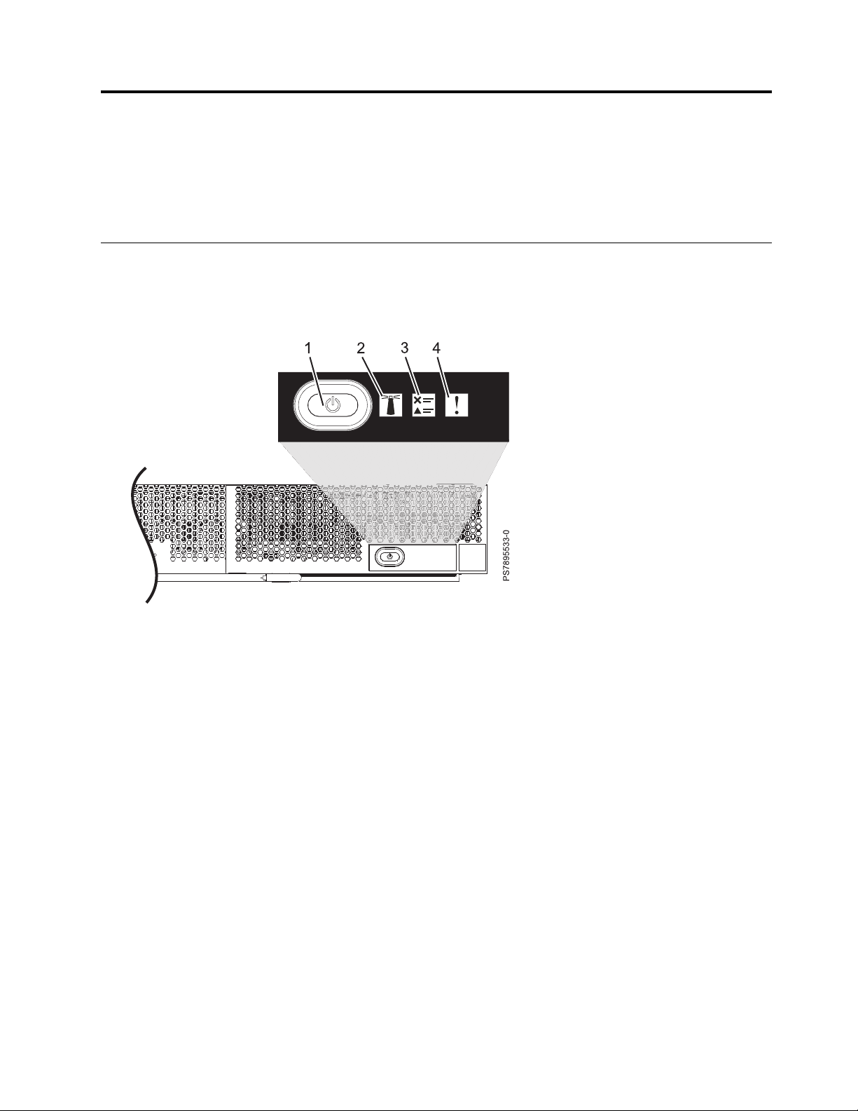
Figure 1. Compute node control panel button and LEDs
1. Power-control button and light path LED: Press this button to turn on or turn off the compute node
or to view light path diagnostic LEDs.
The power-control button has an effect only if local power control is enabled for the compute node.
Local power control is enabled and disabled through the web interface of the management module.
Press the power-control button for 5 seconds to begin powering down the compute node.
The green light path LED indicates the power status of the compute node in the following manner:
v Flashing rapidly: The service processor is initializing the compute node.
v Flashing slowly: The compute node has completed initialization and is waiting for a power-on
command.
v Lit continuously: The compute node has power and is turned on.
Note: The enhanced service processor can take as long as 3 minutes to initialize after you install the
compute node, at which point the LED begins to flash slowly.
2. Location LED: When this blue LED is lit, it has been turned on by the system administrator to aid in
visually locating the compute node. The location LED can be turned off through the management
console.
3. Check log LED: When this amber LED is lit, it indicates that an error for the compute node has been
detected that must be addressed by the user. See the error log repository to further investigate this
serviceable event. The LED can be turned off through the management console.
© Copyright IBM Corp. 2012, 2015 11
Page 24

4. Enclosure fault LED: When this amber LED is lit, it indicates that a system error has occurred in the
compute node. The compute-node error LED will turn off after one of the following events:
v Correcting the error
v Reseating the compute node in the IBM Flex System Enterprise Chassis
v Cycling the IBM Flex System Enterprise Chassis power
Related tasks:
“Viewing the light path diagnostic LEDs” on page 486
After reading the required safety information, look at the control panel to determine whether the LEDs
indicate a suboptimal condition or an error.
Turning on the compute node
After you connect the compute node to power through the IBM Flex System Enterprise Chassis, you can
start the compute node after the discovery and initialization process is complete.
About this task
To start the compute node, use one of the following methods:
Procedure
v Start the compute node by pressing the power-control button on the front of the compute node.
After you push the power-control button, the power-on LED continues to flash slowly for about 15
seconds, and then is lit solidly when the power-on process is complete.
Wait until the power-on LED on the compute node flashes slowly before you press the compute node
power-control button. If the power-on LED is flashing rapidly, the service processor is initializing the
compute node. The power-control button does not respond during initialization.
Note: The enhanced service processor can take as long as 3 minutes to initialize after you install the
compute node, at which point the LED begins to flash slowly.
v Start the compute node automatically when power is restored after a power failure.
If a power failure occurs, the IBM Flex System Enterprise Chassis and then the compute node can start
automatically when power is restored. You must configure the compute node to restart through the
management module.
v Start the compute node remotely using the management module.
After you initiate the power-on process, the power-on LED flashes slowly for about 15 seconds, and
then is lit solidly when the power-on process is complete.
12 Power Systems: IBM Flex System p260 and p460 Compute Nodes Installation and Service Guide
Page 25

Turning off the compute node
When you turn off the compute node, it is still connected to power through the IBM Flex System
Enterprise Chassis. The compute node can respond to requests from the service processor, such as a
remote request to turn on the compute node. To remove all power from the compute node, you must
remove it from the IBM Flex System Enterprise Chassis.
Before you begin
Shut down the operating system before you turn off the compute node. See the operating-system
documentation for information about shutting down the operating system.
About this task
To turn off the compute node, use one of the following methods:
Procedure
v Turn off the compute node by pressing the power-control button for at least 5 seconds.
Note: The power-control LED can remain on solidly for up to 1 minute after you push the
power-control button. After you turn off the compute node, wait until the power-control LED is
flashing slowly before you press the power-control button to turn on the compute node again.
If the operating system stops functioning, press and hold the power-control button for more than 5
seconds to force the compute node to turn off.
v Use the management module to turn off the compute node.
The power-control LED can remain on solidly for up to 1 minute after you initiate the power-off
process. After you turn off the compute node, wait until the power-control LED is flashing slowly
before you initiate the power-on process from the Chassis Management Module (CMM) to turn on the
compute node again.
Use the management-module Web interface to configure the management module to turn off the
compute node if the system is not operating correctly.
For additional information, see http://publib.boulder.ibm.com/infocenter/flexsys/information/topic/
com.ibm.acc.cmm.doc/cmm_product_page.html.
System-board layouts
Illustrations show the connectors and LEDs on the system board. The illustrations might differ slightly
from your hardware.
Chapter 2. Power, controls, indicators, and connectors 13
Page 26
System-board connectors
Compute node components attach to the connectors on the system board.
The following figure shows the connectors on the base-unit system board in the IBM Flex System p260
Compute Node.
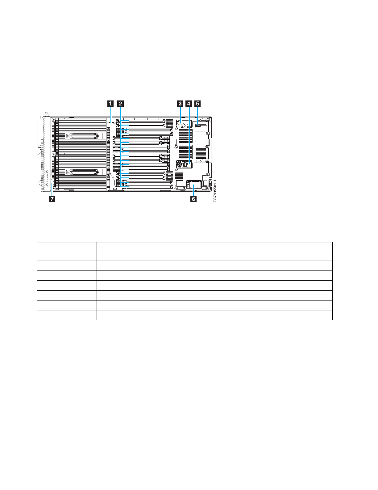
Figure 2. System-board connectors for the IBM Flex System p260 Compute Node
The following table identifies and describes the connectors for the IBM Flex System p260 Compute Node.
Table 2. Connectors for the IBM Flex System p260 Compute Node
Callout IBM Flex System p260 Compute Node connectors
▌1▐ 3 V lithium battery connector (P1-E1)
▌2▐ DIMM connectors (See Figure 4 on page 16 for individual connectors.)
▌3▐ I/O expansion card top connector for chassis bays 1 and 2 (P1-C18)
▌4▐ I/O expansion card bottom connector for chassis bays 3 and 4 (P1-C19)
▌5▐ Management card connector (P1-C21)
▌6▐ Everything-to-Everywhere (ETE) connector (P1-C20)
▌7▐ Light path card
The following figure shows the connectors on the base-unit system board in the IBM Flex System p460
Compute Node.
14 Power Systems: IBM Flex System p260 and p460 Compute Nodes Installation and Service Guide
Page 27
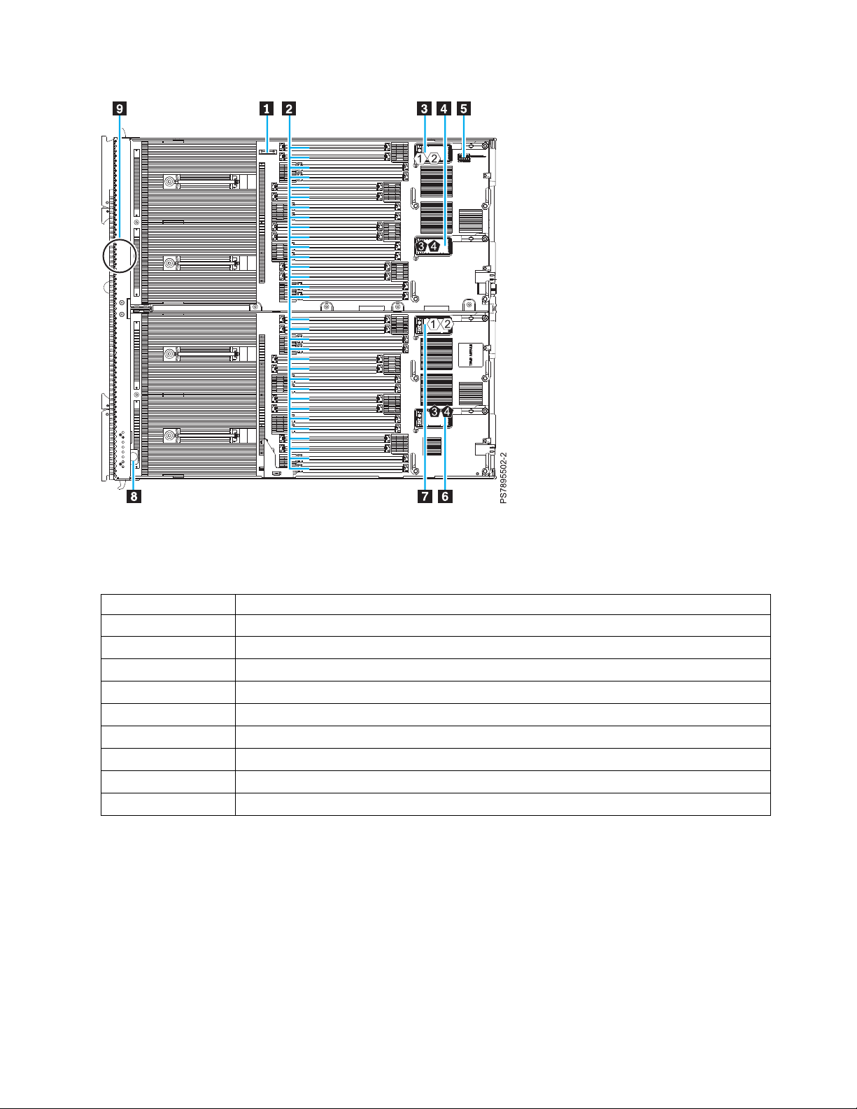
Figure 3. Base-unit connectors for the IBM Flex System p460 Compute Node
The following table identifies and describes the connectors for the IBM Flex System p460 Compute Node.
Table 3. Connectors for the IBM Flex System p460 Compute Node
Callout IBM Flex System p460 Compute Node connectors
▌1▐ 3 V lithium battery connector (P1-E1)
▌2▐ DIMM connectors (See Figure 5 on page 16 for individual connectors.)
▌3▐ I/O expansion card M1 connector for chassis bays 1 and 2 (P1-C34)
▌4▐ I/O expansion card M2 connector for chassis bays 3 and 4 (P1-C35)
▌5▐ Management card connector (P1-C38)
▌6▐ I/O expansion card M4 connector for chassis bays 3 and 4 (P1-C37)
▌7▐ I/O expansion card M3 connector for chassis bays 1 and 2 (P1-C36)
▌8▐ Light path card
▌9▐ Thermal sensor
The following figure shows individual DIMM connectors for the IBM Flex System p260 Compute Node
system board.
Chapter 2. Power, controls, indicators, and connectors 15
Page 28
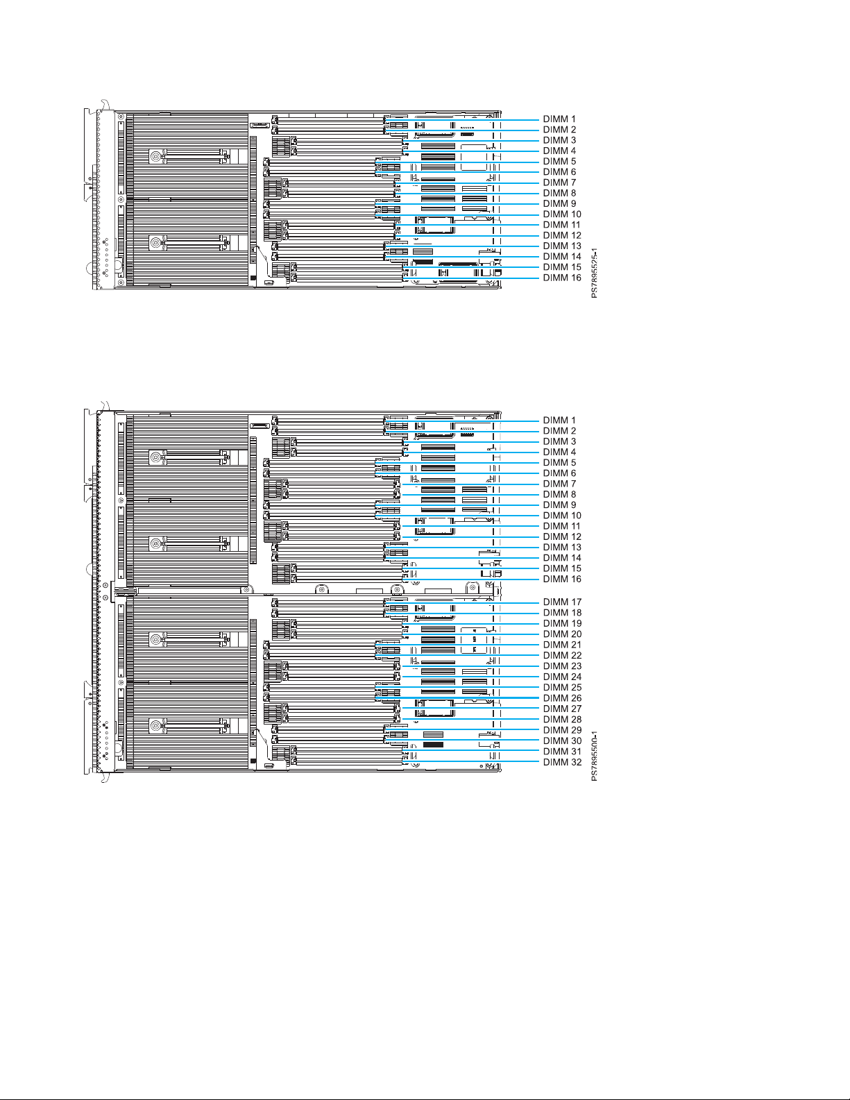
Figure 4. DIMM connectors for the IBM Flex System p260 Compute Node
The following figure shows individual DIMM connectors for the IBM Flex System p460 Compute Node
system board.
Figure 5. DIMM connectors for the IBM Flex System p460 Compute Node
16 Power Systems: IBM Flex System p260 and p460 Compute Nodes Installation and Service Guide
Page 29
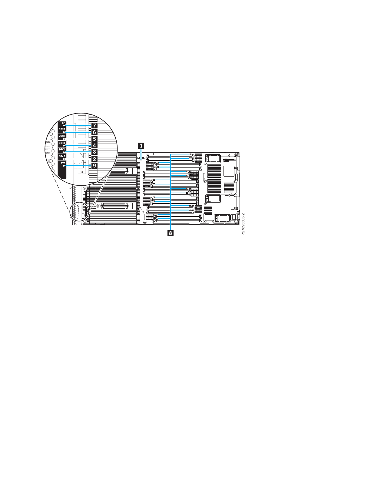
System-board LEDs
Use the illustration of the LEDs on the system board to identify a light emitting diode (LED).
Press and hold the front power-control button to see any light path diagnostic LEDs that were turned on
during error processing. Use the following figure to identify the failing component.
The following figure shows LEDs on the IBM Flex System p260 Compute Node. The following figures
and table shows the system-board LEDs.
Figure 6. LED locations on the system board of the IBM Flex System p260 Compute Node
The following figure shows LEDs on the system board of the IBM Flex System p460 Compute Node.
Chapter 2. Power, controls, indicators, and connectors 17
Page 30

Figure 7. LED locations on the system board of the IBM Flex System p460 Compute Node
The following table identifies the light path diagnostic LEDs.
Table 4. IBM Flex System p260 Compute Node and IBM Flex System p460 Compute Node LEDs
Callout Unit LEDs
▌1▐ 3 V lithium battery LED
▌2▐ DRV2 LED (HDD or SSD)
▌3▐ DRV1 LED (HDD or SSD)
▌4▐ Drive board LED (solid-state drive interposer, which is integrated in the cover)
▌5▐ Management card LED
▌6▐ System board LED
▌7▐ Light path power LED
▌8▐ DIMM LEDs
▌9▐ ETE connector LED
18 Power Systems: IBM Flex System p260 and p460 Compute Nodes Installation and Service Guide
Page 31

Input/output connectors and devices
The input/output connectors that are available to the compute node are supplied by the IBM Flex System
Enterprise Chassis.
See the documentation that comes with the IBM Flex System Enterprise Chassis for information about the
input/output connectors.
The Ethernet controllers on the compute node communicate with the network through the
Ethernet-compatible I/O modules on the IBM Flex System Enterprise Chassis.
Chapter 2. Power, controls, indicators, and connectors 19
Page 32

20 Power Systems: IBM Flex System p260 and p460 Compute Nodes Installation and Service Guide
Page 33

Chapter 3. Configuring the compute node
While the firmware is running Power on System Test (POST) and before the operating system starts, a
POST menu with POST indicators is displayed. The POST indicators are the words Memory, Keyboard,
Network, SCSI, and Speaker that are displayed as each component is tested. You can then select
configuration utilities from the POST menu.
About this task
The following configuration utilities are available from the POST menu:
v System management services (SMS)
Use the system management services (SMS) utility to view information about your system or partition
and to perform tasks such as setting up remote IPL, changing self-configuring SCSI device (SCSD)
settings, and selecting boot options. The SMS utility can be used for AIX®or Linux partitions.
v Default boot list
Use this utility to initiate a system boot in service mode through the default service mode boot list.
This mode attempts to boot from the first device of each type that is found in the list.
Note: This is the preferred method of starting the stand-alone AIX diagnostics from CD.
v Stored boot list
Use this utility to initiate a system boot in service mode by using the customized service-mode boot
list that was set up by the AIX operating system when the operating system was first booted, or
manually by using the AIX service aids.
v Open firmware prompt
This utility is for advanced users of the IEEE 1275 specifications only.
v Management module
Use the management module to change the boot list to determine which firmware image to boot, and
to perform other configuration tasks.
Related tasks:
“Using the SMS utility” on page 24
Use the System Management Services (SMS) utility to configure the IBM Flex System p260 Compute
Node or IBM Flex System p460 Compute Node.
© Copyright IBM Corp. 2012, 2015 21
Page 34

Updating the firmware
IBM periodically makes firmware updates available for you to install on the compute node, on the
management module, or on expansion cards in the compute node.
Before you begin
Attention: Installing the wrong firmware update might cause the compute node to malfunction. Before
you install a firmware update, read any readme and change history files that are provided with the
downloaded update. These files contain important information about the update and the procedure for
installing the update, including any special procedure for updating from an early firmware version to the
latest version.
Important:
v To avoid problems and to maintain proper system performance, always verify that the compute node
BIOS, service processor, and diagnostic firmware levels are consistent for all compute nodes within the
IBM Flex System Enterprise Chassis.
v For a detailed summary of update procedures for all IBM Flex System components, see the
http://www.ibm.com/support/entry/portal/docdisplay?lndocid=MIGR-5091991.
To update the firmware of the compute node, use one of the following methods.
v The IBM Flex System Manager. See http://publib.boulder.ibm.com/infocenter/flexsys/information/
topic/com.ibm.acc.8731.doc/updating_firmware_and_software.html.
v The Hardware Management Console (HMC). See Managed system updates.
v The Integrated Virtualization Manager (IVM), see Updating the Integrated Virtualization Manager.
v In-band operating system capabilities. These include the update_flash command for the Linux
operating system and the AIX operating system or the ldfware command for Virtual I/O Server.
v The firmware update function of AIX diagnostics.
v The firmware update function of the stand-alone diagnostics boot image.
Attention: Before the installation of the new firmware to the temporary side begins, the contents of the
temporary side are copied into the permanent side. After the firmware installation begins, the previous
level of firmware on the permanent side is no longer available.
Notes:
v You must use the default USERID account and password in the management software to access a
Chassis Management Module (CMM) that is managing a chassis that contains Power Systems
compute nodes.
v Before you update the firmware for one or more Power Systems compute nodes, make sure that the
password for the default USERID account will not expire before the update is complete. If the
password expires during a code update, then the Power Systems compute nodes might not reconnect
to the management software, and each Power Systems compute node might have to be updated with
the new password.
v Firmware updates can take some time to load. To expedite the initial setup process, you can begin to
install your operating system while you wait for the firmware updates.
™
22 Power Systems: IBM Flex System p260 and p460 Compute Nodes Installation and Service Guide
Page 35

About this task
To install compute node firmware using an in-band method, complete the following steps:
Procedure
1. Download the IBM Flex System p260 Compute Node one-bay firmware or the IBM Flex System p460
Compute Node two-bay firmware.
a. Go to http://www.ibm.com/software/brandcatalog/puresystems/centre/update.
b. Select the update group that matches the IBM Flex System version to which you want to update.
For example, select the Flex System 1.2.1 tab.
c. Select the updates for the applicable compute node.
d. Download the compute node firmware and any firmware required for installed devices, such as
adapters or drives.
Note: Ensure that you download all files in the firmware update, including .rpm, .xml, dd.xml,
and pd.sdd files as well as the readme.txt file.
e. Use FTP to copy the update to a directory on the compute node (such as /tmp/fwrpms).
2. Log on to the AIX or Linux system as root, or log on to the Virtual I/O Server (VIOS) as padmin.
3. If you are logging on to VIOS, run the following command to obtain root access:
run oem_setup_env
4. Unpack the .rpm file.
For example, if you are installing the FW773 service pack 01AF773_051_033:
rpm -Uvh -ignoreos 01AF773_051_033.rpm
The output from the command should be similar to:
Preparing... #################################### [100%]
1:01AF773_051_033 #################################### [100%]
The resulting .img file is now in the /tmp/fwupdate subdirectory.
5. Install the firmware update with one of the following methods:
v Install the firmware with the AIX update_flash command:
cd /tmp/fwupdate
/usr/lpp/diagnostics/bin/update_flash -f 01AFxxx_yyy_zzz.img
v Install the firmware with the Linux update_flash command:
cd /tmp/fwupdate
/usr/sbin/update_flash -f 01AFxxx_yyy_zzz.img
v Return to VIOS and install the firmware with the ldfware command on VIOS:
#exit
cd /tmp/fwupdate
ldfware -file 01AFxxx_yyy_zzz.img
Where 01AFxxx_yyy_zzz.img is the name of the firmware image.
Note: You can also use the firmware update function of AIX diagnostics or the firmware update
function of the stand-alone diagnostics boot image. For more information, see http://
publib.boulder.ibm.com/infocenter/powersys/v3r1m5/topic/p7ha5/fix_aix_diags.htm.
Chapter 3. Configuring the compute node 23
Page 36

6. Restart the compute node to apply the firmware update.
7. Run the following command in AIX or Linux to verify if the firmware update was successful:
lsmcode -A
Run the following command in VIOS to verify if the firmware update was successful:
lsfware -all
Starting the TEMP image
The system firmware is contained in separate temporary and permanent images in the flash memory of
the compute node. These images are referred to as TEMP and PERM, respectively. The compute node
normally starts from the TEMP image. Start the TEMP image before you update the firmware.
About this task
To start the TEMP image, see http://publib.boulder.ibm.com/infocenter/flexsys/information/topic/
com.ibm.acc.psm.hosts.doc/dpsm_managing_hosts_power_firmware.html.
Verifying the system firmware levels
The diagnostics program displays the current system firmware levels for the temporary (TEMP) and
permanent (PERM) images. This function also displays which image the compute node used to start.
Procedure
1. Start the diagnostics program.
2. From the Function Selection menu, select Task Selection and press Enter.
3. From the Tasks Selection List menu, select Update and Manage System Flash and press Enter.
The top of the Update and Manage System Flash menu displays the system firmware level for the
PERM and the TEMP images and the image that the compute node used to start.
Note: If the TEMP image level is more current than the PERM image, commit the TEMP image.
4. When you have verified the firmware levels, press F3 until the Diagnostic Operating Instructions
window is displayed, and then press F3 again to exit the diagnostic program.
Using the SMS utility
Use the System Management Services (SMS) utility to configure the IBM Flex System p260 Compute
Node or IBM Flex System p460 Compute Node.
24 Power Systems: IBM Flex System p260 and p460 Compute Nodes Installation and Service Guide
Page 37

Starting the SMS utility
Start the SMS utility to configure the compute node.
Procedure
1. Turn on or restart the compute node, and establish an SOL session with it.
See the IBM Chassis Management Module Command-Line Interface Reference Guide for more information.
2. When the POST menu and indicators are displayed, and after the word Keyboard is displayed and
before the word Speaker is displayed, press 1.
3. Follow the instructions in the window.
SMS utility menu choices
Select SMS tasks from the SMS utility main menu. Choices on the SMS utility main menu depend on the
version of the firmware in the compute node.
Some menu choices might differ slightly from these descriptions:
v Select Language
Changes the language that is used to display the SMS menus.
v Setup Remote IPL (Initial Program Load)
Enables and sets up the remote startup capability of the compute node or partition.
v Change SCSI Settings
Changes the addresses of the self-configuring SCSI device (SCSD) controllers that are attached to the
compute node.
v Select Console
Selects the console on which the SMS menus are displayed.
v Select Boot Options
Sets various options regarding the installation devices and boot devices.
Note: If a device that you are trying to select is not displayed in the Select Device Type menu, select
List all Devices and select the device from that menu.
v Firmware Boot Side Options
Controls the booting of firmware from the permanent or temporary side.
Creating a CE login
If the compute node is running the AIX operating system, you can create a customer engineer (CE) login.
The CE login is used to perform operating system commands that are required to service the system
without being logged in as a root user.
Chapter 3. Configuring the compute node 25
Page 38

About this task
The CE login must have a role of Run Diagnostics and must be in a primary group of System. This
setting enables the CE login to perform the following tasks:
v Run the diagnostics, including the service aids, certification, and formatting.
v Run all the operating-system commands that are run by system group users.
v Configure and unconfigure devices that are not in use.
In addition, this login can enable the Shutdown Group so that use of the Update System Microcode
service aid and the shutdown and reboot operations are available.
The preferred CE login user name is qserv.
Configuring processor cores
Learn how to increase or decrease the number of active processor cores in the compute node.
You can order your IBM Flex System p260 Compute Node or IBM Flex System p460 Compute Node with
a feature that instructs the factory to reduce the number of active processor cores in the compute node to
reduce software licensing costs. The factory uses the field core override option to reduce the number of
processor cores when feature code 2319: Factory deconfiguration of one core is ordered with a new system.
This option, available on the Advanced System Management Interface (ASMI), reduces the number of
processor cores by one.
The field core override option indicates the number of functional cores that are active in the compute
node. The field core override option provides the capability to increase or decrease the number of active
processor cores in the compute node. The compute node firmware sets the number of active processor
cores to the entered value. The value takes effect when the compute node is rebooted. The field core
override value can be changed only when the compute node is powered off.
You must use this option to increase the number of active processor cores due to increased workload on
the compute node.
To change the number of functional override cores in the compute node, you must access ASMI. See
http://publib.boulder.ibm.com/infocenter/flexsys/information/topic/com.ibm.acc.psm.hosts.doc/
dpsm_managing_hosts_launch_asm.html.
For detailed information about the field core override feature, see http://publib.boulder.ibm.com/
infocenter/powersys/v3r1m5/topic/p7hby/fieldcore.htm.
Related information:
http://publib.boulder.ibm.com/infocenter/powersys/v3r1m5/topic/p7hby/viewprocconfig.htm
26 Power Systems: IBM Flex System p260 and p460 Compute Nodes Installation and Service Guide
Page 39

MAC addresses for integrated Ethernet controllers
Two integrated Ethernet ports are used by the service processor on the IBM Flex System p260 Compute
Node or IBM Flex System p460 Compute Node. Additional Ethernet ports are provided by the feature
cards plugged into the two expansion cards slots. These expansion card Ethernet ports, when used with a
Virtual I/O Server (VIOS), provide virtual logical Ethernet to client logical partitions (LPARs). The VIOS
software uses the logical Ethernet as if they were actual physical ports.
About this task
The Media Access Control (MAC) addresses of the integrated Ethernet ports are listed on a label on the
compute node. The compute node label lists two MAC addresses. The MAC addresses of the integrated
Ethernet ports are displayed in the Chassis Manager in the management software web interface of the
IBM Flex System Manager and in the Hardware Management Console (HMC), and in the Integrated
Virtualization Manager (IVM). The MAC addresses of the logical ports are generated by VIOS.
To view the MAC addresses of the Ethernet ports by using HMC, click HMC Management > Change
Network Settings > LAN Adapters.
To view the MAC addresses of the Ethernet ports by using IVM, click View/Modify TCP/IP Settings >
Properties > Connected Partitions.
Table 5 shows the relative addressing scheme.
Table 5. MAC addressing scheme for physical and logical integrated Ethernet controllers
Relationship to the MAC
Node
Service processor built-in
Enet0
Service processor built-in
Enet1
Logical Ethernet ports Generated by VIOS
Name in management
module
that is listed on the IBM
Flex System p260 Compute
Node or IBM Flex System
p460 Compute Node label
Same as first MAC address 00:1A:64:44:0e:c4
MAC + 1 00:1A:64:44:0e:c5
Example
1. The Integrated Virtualization Manager (IVM), see Updating the Integrated Virtualization Manager.
For more information about planning, deploying, and managing the use of integrated Ethernet
controllers, see the Configuring section of the PowerVM Information Roadmap.
Chapter 3. Configuring the compute node 27
Page 40

Configuring a RAID array
Use this information to configure a RAID array.
About this task
Configuring a RAID array applies to a compute node in which disk drives or solid-state drives are
installed.
Note: When configuring a RAID array, the hard disk drives must use the same type of interface and
must have identical capacity and speed.
Disk drives and solid-state drives in the IBM Flex System p260 Compute Node or IBM Flex System p460
Compute Node can be used to implement and manage various types of RAID arrays in operating
systems that are on the ServerProven list. For the compute node, you must configure the RAID array
through the smit sasdam utility, which is the SAS RAID Disk Array Manager for the AIX operating
system. The AIX Disk Array Manager is packaged with the Diagnostics utilities on the diagnostics CD.
Use the smit sasdam utility to configure the disk drives for use with the SAS controller. For more
information, see http://publib.boulder.ibm.com/infocenter/systems/scope/hw/index.jsp?topic=/p7ebj/
sasusingthesasdiskarraymanager.htm.
Important: Depending on your RAID configuration, you might have to create the array before you install
the operating system in the compute node.
Before you can create a RAID array, you must reformat the drives so that the sector size of the drives
changes from 512 bytes to 528 bytes. If you later decide to remove the drives, delete the RAID array
before you remove the drives. If you decide to delete the RAID array and reuse the drives, you must
reformat the drives so that the sector size of the drives changes from 528 bytes to 512 bytes.
Related information:
http://www.ibm.com/systems/info/x86servers/serverproven/compat/us/
http://publib.boulder.ibm.com/infocenter/systems/scope/hw/index.jsp?topic=/p7ebj/
sasusingthesasdiskarraymanager.htm
28 Power Systems: IBM Flex System p260 and p460 Compute Nodes Installation and Service Guide
Page 41

Chapter 4. Installing the operating system
Before you install the operating system on the compute node, verify that the compute node is installed in
the IBM Flex System Enterprise Chassis, that the management-module firmware is at the latest available
level, and that the compute node is turned on.
About this task
If you are not using an unattended network-installation method to install your operating system, you
must first provide a serial over LAN (SOL) connection to the compute node to install your operating
system. For information about starting an SOL session, see http://publib.boulder.ibm.com/infocenter/
flexsys/information/topic/com.ibm.acc.cmm.doc/dw1kt_cmm_cli_book.pdf.
Important:
v After you install the operating system on the compute node, you must install any service packs or
update packages that come with the operating system. For additional information, see the instructions
that come with your operating-system documentation and the service packs or update packages.
v If you plan to install an Ethernet I/O expansion card, first install the operating system so that the
onboard ports can be recognized and configured before the ports on the I/O expansion card. If you
install the Ethernet I/O expansion card before you install the operating system, the I/O expansion card
ports will be assigned before the onboard ports.
See the ServerProven website for information about supported operating-system versions and all compute
node optional devices.
Locating the installation instructions
You can order the IBM Flex System p260 Compute Node or IBM Flex System p460 Compute Node with
Virtual I/O Server (VIOS), AIX operating-system, or IBM i operating-system already installed. If you did
not order your compute node with these operating systems installed, you can install them as a local
operating system. After installing VIOS, you can install the AIX, Linux, or IBM i operating system as a
client operating system in a logical partition (LPAR).
About this task
After you configure the compute node hardware, go to the operating-system documentation for the latest
operating-system installation instructions. See the following operating system descriptions for more
information:
v Installing Virtual I/O Server
See the Installing section of the PowerVM Information Roadmap.
If you did not order your servers with the VIOS software installed, you can use the Virtual I/O Server
DVD in the product package to install VIOS and set up a virtual environment that supports client
operating systems in logical partitions. You can then install any of the supported operating systems as
a client in an LPAR.
The order of installation of VIOS and the operating systems is important. You can update the firmware
first with the stand-alone Diagnostics CD, but you must install the VIOS software before you install any
other software. The VIOS software creates the Integrated Virtual Manager administrator console and the
first logical partition, which VIOS and Integrated Virtual Manager (IVM) occupy.
After you install VIOS, you can use the IVM and Micro-Partitioning®features to create client partitions
for client operating systems.
v Installing AIX
© Copyright IBM Corp. 2012, 2015 29
Page 42

You can install the AIX operating system by following the installation instructions in the IBM Systems
Information Center.
See the online AIX Installation and migration topic for more information. You can find more
information about AIX in the IBM System p®Information Roadmap on the IBM website.
Note: After you install AIX from CD or DVD, using the keyboard and video interface, run the change
console command and restart the compute node to switch the AIX console to a Serial over LAN (SOL)
connection. (The command does not affect the console that is used by partition firmware.) You can use
the following commands:
chcons /dev/vty0
shutdown -Fr
v Installing IBM i
You can install the IBM i operating system in a client partition of the VIOS.
See the IBM i on a POWER Blade Read-me First document on the IBM website. Additional installation
information and IBM i restrictions are described in i5/OS™client partition considerations.
Also, see the IBM System i®Information Roadmap.
v Installing Linux
You can install a Linux operating system by following the installation instructions in the IBM Systems
Information Center.
The online Linux installation instructions are available in the Linux on BladeCenter JS22 topic in the IBM
Systems Information Center.
Notes:
1. Some optional devices have device drivers that you must install. See the documentation that comes
with the devices for information about installing any required device drivers.
If your operating system does not have the required device drivers, contact your IBM marketing
representative or authorized reseller, or see your operating-system documentation for additional
information.
2. The IBM Remote Deployment Manager (RDM) program does not support the IBM Flex System p260
Compute Node or IBM Flex System p460 Compute Node. However, you can use the following
programs for remote deployment:
v For AIX, Red Hat Linux or SUSE Linux operating-system deployments, you can use Cluster
Systems Management (CSM) from IBM. Go to http://www.ibm.com/systems/clusters/index.html.
v For AIX operating-system deployments, you can use Network Installation Manager (NIM) from
IBM. See your AIX operating-system documentation for additional information.
v For SUSE Linux operating-system deployments, you can use the AutoYast utility program from
Novell, Inc. Go to http://www.suse.com/~ug/.
30 Power Systems: IBM Flex System p260 and p460 Compute Nodes Installation and Service Guide
Page 43

Results
After you install the operating system, install operating system updates, and then install any utilities that
apply to your operating system.
Installing service and productivity tools for Linux
Linux service and productivity tools include hardware diagnostic aids and productivity tools, and
installation aids. The installation aids are provided in the IBM Installation Toolkit for the Linux operating
system, a set of tools that aids the installation of the Linux operating system on IBM compute nodes that
are based on IBM POWER7 Architecture technologies. You can also use the tools to update the IBM Flex
System p260 Compute Node or IBM Flex System p460 Compute Node firmware.
About this task
The hardware diagnostic aids and productivity tools are available as downloadable Red Hat Package
Manager (RPM) files for Red Hat Enterprise Linux (RHEL) and SUSE Linux Enterprise Server (SLES). The
IBM Installation Toolkit for Linux is available as an ISO compact disc (CD) image, which you can use to
create your own CD. The Service and productivity tools for Linux systems site describes how to create a
CD.
The hardware diagnostic aids and productivity tools are required for such hardware reliability,
availability, and serviceability (RAS) functions as first-failure data-capture and error-log analysis. With the
tools installed, problem determination and correction are greatly enhanced and the likelihood of an
extended system outage is reduced.
For example, the update_flash command for installing system firmware updates can be performed only if
the hardware diagnostic aids and productivity tools are installed.
Other tools modify various serviceability policies, manipulate system LEDs, update the bootlist, and
capture extended error data to aid analysis of intermittent errors.
Other commands and a boot-time scanning script constitute a hardware inventory system. The lsvpd
command provides vital product data (VPD) about hardware components.
The Error Log Analysis (ELA) tool provides automatic analysis and notification of errors that are reported
by the platform firmware. ELA writes analyzed error data to /var/log/platform and to the service log. If
a corrective action is required, a notification event sends the event to registered tools and subscribed
users.
Install the Linux operating system before you download and install the hardware diagnostic aids and
productivity tools for Linux. The Installation Toolkit for Power Systems servers running Linux is
provided as-is only. You are not entitled to IBM Software Support for the Installation Toolkit.
Install the Virtual I/O Server and the Integrated Virtualization Manager before you install your Linux
operating system if you plan to have a virtual environment.
Chapter 4. Installing the operating system 31
Page 44

32 Power Systems: IBM Flex System p260 and p460 Compute Nodes Installation and Service Guide
Page 45

Chapter 5. Accessing the service processor
You can access the service processor remotely.
The management console can connect directly to the Advanced System Management Interface (ASMI) for
a selected system. ASM is an interface to the service processor that you can use to manage the operation
of the host, such as the automatic power restart function, and to view information about the host, such as
the error log and vital product data.
To access the ASMI by using the IBM Flex System Manager, see Launching Advanced System
Management (http://publib.boulder.ibm.com/infocenter/flexsys/information/topic/
com.ibm.acc.psm.hosts.doc/dpsm_managing_hosts_launch_asm.html).
To access the ASMI by using the Hardware Management Console (HMC), see Accessing the ASMI using
the HMC (http://pic.dhe.ibm.com/infocenter/powersys/v3r1m5/topic/p7hby/asmihmc.htm).
To access the ASMI by using a web browser, complete the following steps:
1. Assign an IP address to the service processor of the compute node. Perform the following steps:
a. Access the Chassis Management Module (CMM) web interface. For instructions, see Ethernet
connection (http://pic.dhe.ibm.com/infocenter/flexsys/information/topic/com.ibm.acc.cmm.doc/
remote_console_ethernet_connect_cmm.html).
b. From the menu bar, click Chassis Management. Then, in the drop-down menu click Component
IP Configuration. From the Device Name list, select the compute node name to access property
tabs for the compute node. On the IPv4 property tab set the static IP address, mask, and gateway.
For more information about setting the IP configuration of a compute node, see Chassis
management options (http://pic.dhe.ibm.com/infocenter/flexsys/information/topic/
com.ibm.acc.cmm.doc/cmm_ui_chassis_management.html).
2. Open a web browser on the client computer. Type https://xxx.xxx.xxx.xxx, where xxx.xxx.xxx.xxx is the
IP address of the compute node service processor.
© Copyright IBM Corp. 2012, 2015 33
Page 46

34 Power Systems: IBM Flex System p260 and p460 Compute Nodes Installation and Service Guide
Page 47

Chapter 6. Installing and removing components
Install or remove hardware components, such as memory modules or input/output expansion cards.
Some installation procedures require you to remove an installed component.
Returning a device or component
If you are instructed to return a device or component, follow all packaging instructions, and use any
packaging materials for shipping that are supplied to you.
Installation guidelines
Follow these guidelines to remove and replace compute node components.
v Read the safety information in the Safety topic and the guidelines in “Handling static-sensitive
devices” on page 36. This information will help you work safely.
v When you install a new compute node, download and apply the most recent firmware updates.
Download and install updated device drivers and the compute node firmware. Go to the IBM Support
site to download the updates. Select your product, type, model, and operating system, and then click
Go. Click the Download tab, if necessary, for device driver and firmware updates.
Note: Changes are made periodically to the IBM website. Procedures for locating firmware and
documentation might vary slightly from what is described in this documentation.
v Observe good housekeeping in the area where you are working. Place removed covers and other parts
in a safe place.
v Back up all important data before you make changes to disk drives.
v Before you remove a hot-swap compute node from the IBM Flex System Enterprise Chassis, you must
shut down the operating system and turn off the compute node. You do not have to shut down the
IBM Flex System Enterprise Chassis itself.
v Blue on a component indicates touchpoints, where you can grip the component to remove it from or
install it in the compute node, open or close a latch, and so on.
v Orange on a component or an orange label on or near a component indicates that the component can
be hot-swapped, which means that if the compute node and operating system support hot-swap
capability, you can remove or install the component while the compute node is running. (Orange can
also indicate touchpoints on hot-swap components.) See the instructions for removing or installing a
specific hot-swap component for any additional procedures that you might have to perform before you
remove or install the component.
v When you are finished working on the compute node, reinstall all safety shields, guards, labels, and
ground wires.
See the ServerProven website for information about supported operating-system versions and all compute
node optional devices.
© Copyright IBM Corp. 2012, 2015 35
Page 48

System reliability guidelines
Follow these guidelines to help ensure proper cooling and system reliability.
v Verify that the ventilation holes on the compute node are not blocked.
v Verify that you are maintaining proper system cooling in the unit.
Do not operate the IBM Flex System Enterprise Chassis without a compute node, expansion unit, or
filler node installed in each bay. See the documentation for your IBM Flex System Enterprise Chassis
for additional information.
v Verify that you have followed the reliability guidelines for the IBM Flex System Enterprise Chassis.
v Verify that the compute node battery is operational. If the battery becomes defective, replace it
immediately, as described in “Removing the battery” on page 64 and “Installing the battery” on page
65.
Handling static-sensitive devices
Static electricity can damage the compute node and other electronic devices. To avoid damage, keep
static-sensitive devices in their static-protective packages until you are ready to install them.
About this task
Attention:
To reduce the possibility of damage from electrostatic discharge, observe the following precautions:
v Limit your movement. Movement can cause static electricity to build up around you.
v Handle the device carefully, holding it by its edges or its frame.
v Do not touch solder joints, pins, or exposed circuitry.
v Do not leave the device where others can handle and damage it.
v While the device is still in its static-protective package, touch it to an unpainted metal part of the IBM
Flex System Enterprise Chassis or any unpainted metal surface on any other grounded rack component
in the rack that you are installing the device in for at least 2 seconds. This drains static electricity from
the package and from your body.
v Remove the device from its package and install it directly into the compute node without setting down
the device. If it is necessary to set down the device, put it back into its static-protective package. Do
not place the device on the compute node cover or on a metal surface.
v Take additional care when handling devices during cold weather. Heating dry winter air further
reduces its humidity and increases static electricity.
36 Power Systems: IBM Flex System p260 and p460 Compute Nodes Installation and Service Guide
Page 49

Removing the compute node from an IBM Flex System Enterprise Chassis
Remove the compute node from the IBM Flex System Enterprise Chassis to access options, connectors,
and system-board indicators.
About this task
Figure 8. Removing the compute node from the IBM Flex System Enterprise Chassis
Attention:
v To maintain proper system cooling, do not operate the IBM Flex System Enterprise Chassis without a
compute node, expansion unit, or compute node filler installed in each bay.
v When you remove the compute node, note the bay number. Reinstalling a compute node into a
different bay from the one where it was removed might have unintended consequences. Some
configuration information and update options are established according to bay numbers. If you
reinstall the compute node into a different bay, you might have to reconfigure the compute node.
To remove the compute node, complete the following steps:
Procedure
1. Read the Safety topic and the “Installation guidelines” on page 35.
2. If the compute node is operating, shut down the operating system. See “Locating the installation
instructions” on page 29 for information about locating the operating system documentation for your
compute node.
Chapter 6. Installing and removing components 37
Page 50

3. Press the power-control button to turn off the compute node. See “Turning off the compute node” on
page 13.
4. Wait at least 30 seconds for the hard disk drive to stop spinning.
5. Open the release handles, as shown in Figure 8 on page 37. The IBM Flex System p260 Compute
Node has one release handle. The IBM Flex System p460 Compute Nodehas two release handles. The
compute node can be moved out of the bay approximately 0.6 cm (0.25 inch).
6. Pull the compute node out of the bay.
7. Carefully lay the compute node on a flat, static-protective surface, with the cover side up.
8. Place either a compute node filler or another compute node in the bay.
Reseating the compute node in a chassis
Reseat the compute node.
About this task
To reseat the compute node, complete the following steps:
Procedure
1. Perform a virtual reseat of the compute node.
To perform a virtual reseat by using the IBM Chassis Management Module (CMM), go to
http://pic.dhe.ibm.com/infocenter/flexsys/information/topic/com.ibm.acc.8731.doc/
unmanaging_chassis.html.
To perform a virtual reseat by using the IBM Flex System Manager (FSM), go to http://
pic.dhe.ibm.com/infocenter/flexsys/information/topic/com.ibm.acc.8731.doc/
unmanaging_chassis.html.
2. Is the problem resolved?
Yes: This ends the procedure.
No: Continue with the next step.
3. Remove and replace the compute node into the IBM Flex System Enterprise Chassis.
a. Remove the compute node from the IBM Flex System Enterprise Chassis. See “Removing the
compute node from an IBM Flex System Enterprise Chassis” on page 37.
b. Install the compute node into the IBM Flex System Enterprise Chassis. See “Installing the compute
node in an IBM Flex System Enterprise Chassis” on page 93.
38 Power Systems: IBM Flex System p260 and p460 Compute Nodes Installation and Service Guide
Page 51

Removing and replacing tier 1 CRUs
Replacement of tier 1 customer-replaceable units (CRUs) is your responsibility.
About this task
If IBM installs a tier 1 CRU at your request, you will be charged for the installation.
The illustrations in this documentation might differ slightly from your hardware.
Removing the compute node cover
Remove the compute node from the chassis unit and press the compute node cover releases to open and
remove the compute node cover.
About this task
Figure 9. Removing the cover from an IBM Flex System p260 Compute Node
Chapter 6. Installing and removing components 39
Page 52

Figure 10. Removing the cover from an IBM Flex System p460 Compute Node
To remove the compute node cover, complete the following steps:
Procedure
1. Read the Safety topic and the “Installation guidelines” on page 35.
2. Shut down the operating system on all partitions of the compute node, turn off the compute node,
and remove the compute node from the IBM Flex System Enterprise Chassis. See “Removing the
compute node from an IBM Flex System Enterprise Chassis” on page 37.
3. Carefully lay the compute node on a flat, static-protective surface, with the cover side up.
4. Facing the unit, unlatch the cover by pressing the right cover release (as shown in the preceding
figures) on the compute node.
5. Press the right cover release while gripping the left cover release, slide the cover to the back of the
unit, and lift the cover open.
6. To protect the disk drives, which are on the inside of the cover, flip the cover over and lay it on a flat,
static-protective surface, with the cover side down.
Statement 12
CAUTION:
The following label indicates a hot surface nearby.
Statement 21
40 Power Systems: IBM Flex System p260 and p460 Compute Nodes Installation and Service Guide
Page 53

CAUTION:
Hazardous energy is present when the compute node is connected to the power source. Always
replace the compute node cover before installing the compute node.
Installing and closing the compute node cover
Install and close the cover of the compute node before you insert the compute node into the IBM Flex
System Enterprise Chassis. Do not attempt to override this important protection.
About this task
Figure 11. Installing the cover for an IBM Flex System p260 Compute Node
Chapter 6. Installing and removing components 41
Page 54

Figure 12. Installing the cover for an IBM Flex System p460 Compute Node
Statement 21
CAUTION:
Hazardous energy is present when the compute node is connected to the power source. Always replace
the compute node cover before installing the compute node.
To replace and close the compute node cover, complete the following steps:
Procedure
1. Read the Safety topic and the “Installation guidelines” on page 35.
2. Lower the cover so that the pins on the sides of the cover slide down into the slots (as shown in the
preceding figures) at the front and rear of the compute node. Before you close the cover, verify that all
components are installed and seated correctly and that you have not left loose tools or parts inside the
compute node.
42 Power Systems: IBM Flex System p260 and p460 Compute Nodes Installation and Service Guide
Page 55

3. Slide the cover forward to the closed position until the releases click into place in the cover.
4. Install the compute node into the IBM Flex System Enterprise Chassis. See “Installing the compute
node in an IBM Flex System Enterprise Chassis” on page 93.
Removing the bezel assembly
If a bezel is damaged, you can remove it from a compute node.
About this task
Removal of the bezel assembly is not required for servicing internal components of your IBM Flex System
p260 Compute Node or IBM Flex System p460 Compute Node. If the bezel becomes damaged, you can
remove the bezel by using the following procedure.
Figure 13. Removing the bezel assembly from an IBM Flex System p260 Compute Node
Chapter 6. Installing and removing components 43
Page 56

Figure 14. Removing the bezel assembly from an IBM Flex System p460 Compute Node
To remove the compute node bezel, complete the following steps:
Procedure
1. Read the Safety topic and the “Installation guidelines” on page 35.
2. Shut down the operating system on all partitions of the compute node, turn off the compute node,
and remove the compute node from the IBM Flex System Enterprise Chassis. See “Removing the
compute node from an IBM Flex System Enterprise Chassis” on page 37.
3. Carefully lay the compute node on a flat, static-protective surface, with the cover side up.
4. Locate the bezel on the right-front side of the compute node. Holding both sides of the bezel
assembly, pull the bezel assembly away from the compute node as shown in Figure 13 on page 43 and
Figure 14.
5. If you are instructed to return the bezel assembly, follow all packaging instructions, and use any
packaging materials for shipping that are supplied to you.
44 Power Systems: IBM Flex System p260 and p460 Compute Nodes Installation and Service Guide
Page 57

Installing the bezel assembly
You can replace a damaged bezel on an IBM Flex System p260 Compute Node or IBM Flex System p460
Compute Node.
About this task
If the bezel becomes damaged, you can install a new bezel by using the following procedure.
Figure 15. Installing the bezel assembly in an IBM Flex System p260 Compute Node
Chapter 6. Installing and removing components 45
Page 58

Figure 16. Installing the bezel assembly in an IBM Flex System p460 Compute Node
To replace a bezel on the compute node, complete the following steps:
Procedure
1. Align the bezel with the compute node according to the circled locations indicated in Figure 15 on
page 45 and Figure 16.
2. Align the bezel assembly with the front of the compute node. Firmly press the bezel at the sides
where the two pins protrude from the face of the compute node until the assembly clicks into place.
3. Install the compute node into the IBM Flex System Enterprise Chassis. See “Installing the compute
node in an IBM Flex System Enterprise Chassis” on page 93.
Removing a SAS hard disk drive
If the serial-attached SCSI (SAS) hard disk drive is damaged or in need of replacing, you can remove it
from the compute node.
46 Power Systems: IBM Flex System p260 and p460 Compute Nodes Installation and Service Guide
Page 59

About this task
Figure 17. Removing a hard disk drive
To remove the hard disk drive, complete the following steps:
Procedure
1. Back up the data from the drive to another storage device.
2. Read the Safety topic and the “Installation guidelines” on page 35.
3. Shut down the operating system on all partitions of the compute node, turn off the compute node,
and remove the compute node from the IBM Flex System Enterprise Chassis. See “Removing the
compute node from an IBM Flex System Enterprise Chassis” on page 37.
4. Carefully lay the compute node on a flat, static-protective surface, with the cover side up.
5. Open and remove the compute node cover. See “Removing the compute node cover” on page 39.
6. Remove the drive, which is on the inside of the cover:
Note: You can use the system-board LEDs and the service label located on the inside of the cover to
identify the hard disk drive that must be replaced. See “System-board LEDs” on page 17.
a. Move and hold the blue release lever at the front of the drive tray, as indicated in Figure 17.
b. Slide the drive forward to disengage the connector.
c. Lift the drive out of the drive tray.
Chapter 6. Installing and removing components 47
Page 60

7. If you are instructed to return the hard disk drive, follow all packaging instructions, and use any
packaging materials for shipping that are supplied to you.
Installing a SAS hard disk drive
If your serial-attached SCSI (SAS) hard disk drive needs replacing, install another SAS hard drive in the
compute node.
About this task
Figure 18 shows how to install the hard disk drive.
Figure 18. Installing a hard disk drive
All drive connectors are from the same controller. Both the IBM Flex System p260 Compute Node and
IBM Flex System p460 Compute Node can be used to implement RAID functions. See “Configuring a
RAID array” on page 28 for information about RAID configuration.
To install a hard disk drive, complete the following steps:
Procedure
1. Read the Safety topic and the “Installation guidelines” on page 35.
48 Power Systems: IBM Flex System p260 and p460 Compute Nodes Installation and Service Guide
Page 61

2. Shut down the operating system on all partitions of the compute node, turn off the compute node,
and remove the compute node from the IBM Flex System Enterprise Chassis. See “Removing the
compute node from an IBM Flex System Enterprise Chassis” on page 37.
3. Carefully lay the compute node on a flat, static-protective surface, with the cover side up.
4. Open and remove the compute node cover. See “Removing the compute node cover” on page 39.
5. Locate the connector for the drive on the inside of the cover.
v If you are replacing a drive, continue to the next step.
v If you are installing a new drive, remove the filler:
a. Move and hold the blue release lever at the front of the drive tray.
b. Slide the filler forward and lift it out of the drive tray.
6. Place the drive into the drive tray and push it toward the rear of the compute node, as indicated in
Figure 18 on page 48. When the drive moves past the lever at the front of the tray, it snaps in place.
Attention: Do not press on the top of the drive. Pressing the top might damage the drive.
7. Install and close the compute node cover. See “Installing and closing the compute node cover” on
page 41.
Statement 21
CAUTION:
Hazardous energy is present when the compute node is connected to the power source. Always
replace the compute node cover before installing the compute node.
8. Install the compute node into the IBM Flex System Enterprise Chassis. See “Installing the compute
node in an IBM Flex System Enterprise Chassis” on page 93.
9. If you replaced the part because of a service action, verify the repair by checking that the amber
enclosure fault LED is off. For more information, see “Compute node control panel button and LEDs”
on page 11.
Removing a solid-state drive carrier
If your solid-state drive (SSD) carrier needs to be replaced, you can remove it from the compute node.
About this task
Chapter 6. Installing and removing components 49
Page 62

Figure 19. Removing an SSD carrier
To remove the drive, complete the following steps:
Procedure
1. Back up the data from the drive to another storage device.
2. Read the Safety topic and the “Installation guidelines” on page 35.
3. Shut down the operating system on all partitions of the compute node, turn off the compute node,
and remove the compute node from the IBM Flex System Enterprise Chassis. See “Removing the
compute node from an IBM Flex System Enterprise Chassis” on page 37.
4. Carefully lay the compute node on a flat, static-protective surface, with the cover side up.
5. Open and remove the compute node cover. See “Removing the compute node cover” on page 39.
6. Remove the drive, which is on the inside of the cover:
Note: You can use the system-board LEDs and the service label located on the inside of the cover to
identify the solid-state drive that must be replaced. See “System-board LEDs” on page 17.
a. Pull and hold the blue release lever at the front of the drive tray, as indicated in Figure 19.
b. Slide the carrier case forward to disengage the connector.
c. Lift the carrier case out of the drive tray.
50 Power Systems: IBM Flex System p260 and p460 Compute Nodes Installation and Service Guide
Page 63

7. Remove any SSDs from the carrier case. See “Removing a SATA solid-state drive” on page 53.
8. If you are instructed to return the SSD carrier, follow all packaging instructions, and use any
packaging materials for shipping that are supplied to you.
Note: Even if you do not plan to install another SSD in the drive slot, replace the SSD carrier in the
slot to act as a thermal baffle and to avoid machine damage. See “Installing a solid-state drive
carrier.”
Installing a solid-state drive carrier
If your solid-state drive (SSD) carrier needs to be replaced, you can install another carrier in the compute
node.
About this task
Figure 20 shows how to install the disk drive.
Figure 20. Installing an SSD carrier
To install an SSD carrier, complete the following steps:
Procedure
Chapter 6. Installing and removing components 51
Page 64

1. Read the Safety topic and the “Installation guidelines” on page 35.
2. Shut down the operating system on all partitions of the compute node, turn off the compute node,
and remove the compute node from the IBM Flex System Enterprise Chassis. See “Removing the
compute node from an IBM Flex System Enterprise Chassis” on page 37.
3. Carefully lay the compute node on a flat, static-protective surface, with the cover side up.
4. Open and remove the compute node cover. See “Removing the compute node cover” on page 39.
5. Locate the connector for the drive.
Note: Although the SSD carrier and the HDD are two separately configured cards, the SSD carrier
case plugs in to the 2.5 inch SAS HDD connector.
6. If you are replacing an SSD carrier, continue to the next step. If you are installing a new SSD carrier,
remove the filler to vacate the space for the new SSD carrier:
a. Pull and hold the blue release lever at the front of the drive tray.
b. Slide the filler forward to disengage the connector.
c. Lift the filler out of the drive tray.
7. Remove the SSD carrier case that you want to replace from the drive tray. See “Removing a
solid-state drive carrier” on page 49.
8. Install SSDs into the new carrier case. See “Installing a SATA solid-state drive” on page 54.
9. Place the carrier case into the drive tray and push it toward the rear of the compute node, as
indicated in Figure 20 on page 51. When the SSD carrier moves past the lever at the front of the tray,
it snaps in place.
Attention: Do not press the top of the carrier case. Pressing the top might damage the drive.
10. Install and close the compute node cover. See “Installing and closing the compute node cover” on
page 41.
Statement 21
CAUTION:
Hazardous energy is present when the compute node is connected to the power source. Always
replace the compute node cover before installing the compute node.
11. Install the compute node into the IBM Flex System Enterprise Chassis. See “Installing the compute
node in an IBM Flex System Enterprise Chassis” on page 93.
12. If you replaced the part because of a service action, verify the repair by checking that the amber
enclosure fault LED is off. For more information, see “Compute node control panel button and
LEDs” on page 11.
52 Power Systems: IBM Flex System p260 and p460 Compute Nodes Installation and Service Guide
Page 65

Removing a SATA solid-state drive
If your Serial Advanced Technology Attachment (SATA) solid-state drive (SSD) needs to be replaced, you
can remove it from the compute node.
About this task
Figure 21. Removing a SATA SSD
To remove the SATA SSD, complete the following steps:
Procedure
1. Back up the data from the drive to another storage device.
2. Read the Safety topic and the “Installation guidelines” on page 35.
3. Shut down the operating system on all partitions of the compute node, turn off the compute node,
and remove the compute node from the IBM Flex System Enterprise Chassis. See “Removing the
compute node from an IBM Flex System Enterprise Chassis” on page 37.
4. Carefully lay the compute node on a flat, static-protective surface, with the cover side up.
5. Open and remove the compute node cover. See “Removing the compute node cover” on page 39.
6. Remove the SSD carrier from the drive tray. See “Removing a solid-state drive carrier” on page 49.
Note: You can use the system-board LEDs and the service label located on the inside of the cover to
identify the solid-state drive that must be replaced. See “System-board LEDs” on page 17.
Chapter 6. Installing and removing components 53
Page 66

7. Gently spread open the carrier with your fingers while sliding the SSD out of the carrier case with
your thumbs.
8. If you are instructed to return the drive, follow all packaging instructions, and use any packaging
materials for shipping that are supplied to you.
Installing a SATA solid-state drive
You can install a Serial Advanced Technology Attachment (SATA) solid-state drive (SSD) in a compute
node.
About this task
Figure 22 shows how to install the SATA SSD.
Figure 22. Installing a SATA SSD
To install a SATA SSD, complete the following steps:
Procedure
1. Read the Safety topic and the “Installation guidelines” on page 35.
2. Shut down the operating system on all partitions of the compute node, turn off the compute node,
and remove the compute node from the IBM Flex System Enterprise Chassis. See “Removing the
compute node from an IBM Flex System Enterprise Chassis” on page 37.
3. Carefully lay the compute node on a flat, static-protective surface, with the cover side up.
4. Open and remove the compute node cover. See “Removing the compute node cover” on page 39.
5. Locate the connector for the drive.
6. Remove the SSD carrier case from the drive tray. See “Removing a solid-state drive carrier” on page
49.
7. Slide the SSD into the carrier case until it snaps in place.
54 Power Systems: IBM Flex System p260 and p460 Compute Nodes Installation and Service Guide
Page 67

8. Replace the carrier case in the drive tray. See “Installing a solid-state drive carrier” on page 51.
Attention: Do not press the top of the drive. Pressing the top might damage the drive.
9. Install and close the compute node cover. See “Installing and closing the compute node cover” on
page 41.
Statement 21
CAUTION:
Hazardous energy is present when the compute node is connected to the power source. Always
replace the compute node cover before installing the compute node.
10. Install the compute node into the IBM Flex System Enterprise Chassis. See “Installing the compute
node in an IBM Flex System Enterprise Chassis” on page 93.
11. If you replaced the part because of a service action, verify the repair by checking that the amber
enclosure fault LED is off. For more information, see “Compute node control panel button and
LEDs” on page 11.
Removing a DIMM
The very low profile (VLP) dual-inline memory module (DIMM) is a tier 1 CRU. You can remove it
yourself. If IBM removes a tier 1 CRU at your request, you will be charged for the removal. The low
profile (LP) DIMM is a tier 2 CRU. You can remove it yourself or request IBM to remove it, at no
additional charge, under the type of warranty service that is designated for the compute node.
About this task
To remove a DIMM, complete the following steps:
Procedure
1. Read the Safety topic and the “Installation guidelines” on page 35.
2. Shut down the operating system on all partitions of the compute node, turn off the compute node,
and remove the compute node from the IBM Flex System Enterprise Chassis. See “Removing the
compute node from an IBM Flex System Enterprise Chassis” on page 37.
3. Carefully lay the compute node on a flat, static-protective surface, with the cover side up.
4. Open and remove the compute node cover. See “Removing the compute node cover” on page 39.
5. Locate the DIMM connector that contains the DIMM being replaced.
Note: You can use the system-board LEDs and the service label located on the inside of the cover to
identify the DIMM that must be replaced. See “System-board LEDs” on page 17.
Chapter 6. Installing and removing components 55
Page 68

Figure 23. DIMM connectors for the IBM Flex System p260 Compute Node
Figure 24. DIMM connectors for the IBM Flex System p460 Compute Node
Attention: To avoid breaking the DIMM retaining clips or damaging the DIMM connectors, open
and close the clips gently.
56 Power Systems: IBM Flex System p260 and p460 Compute Nodes Installation and Service Guide
Page 69

6. Carefully open the retaining clips (A) on each end of the DIMM connector by pressing them in the
direction of the arrows. Remove the DIMM (B).
Figure 25. Removing a DIMM
7. Install a DIMM filler (C) in any location where a DIMM is not present to avoid machine damage.
Note: Before you replace the compute node cover, ensure that you have at least the minimum
DIMM configuration installed so that your compute node operates properly.
8. If you are instructed to return the DIMM, follow all packaging instructions, and use any packaging
materials for shipping that are supplied to you.
9. Install and close the compute node cover. See “Installing and closing the compute node cover” on
page 41.
Statement 21
CAUTION:
Hazardous energy is present when the compute node is connected to the power source. Always
replace the compute node cover before installing the compute node.
10. Install the compute node into the IBM Flex System Enterprise Chassis. See “Installing the compute
node in an IBM Flex System Enterprise Chassis” on page 93.
Chapter 6. Installing and removing components 57
Page 70

Installing a DIMM
The very low profile (VLP) dual-inline memory module (DIMM) is a tier 1 CRU. You can install it
yourself. If IBM installs a tier 1 CRU at your request, you will be charged for the installation. The low
profile (LP) DIMM is a tier 2 CRU. You can install it yourself or request IBM to install it, at no additional
charge, under the type of warranty service that is designated for the compute node.
About this task
To install a DIMM, complete the following steps:
Procedure
1. Read the Safety topic and the “Installation guidelines” on page 35.
2. Read the documentation that comes with the DIMMs.
3. Shut down the operating system on all partitions of the compute node, turn off the compute node,
and remove the compute node from the IBM Flex System Enterprise Chassis. See “Removing the
compute node from an IBM Flex System Enterprise Chassis” on page 37.
4. Carefully lay the compute node on a flat, static-protective surface, with the cover side up.
5. Open and remove the compute node cover. See “Removing the compute node cover” on page 39.
6. Locate the DIMM connectors on the system board. Determine the connector into which you will
install the DIMM. See “Supported DIMMs” on page 59.
7. Touch the static-protective package that contains the part to any unpainted metal surface on the IBM
Flex System Enterprise Chassis or any unpainted metal surface on any other grounded rack
component, and then remove the new part from its shipment package.
8. Verify that both of the connector retaining clips are in the fully open position.
9. Turn the DIMM so that the DIMM keys align correctly with the connector on the system board.
Attention: To avoid breaking the DIMM retaining clips or damaging the DIMM connectors, handle
the clips gently.
10. Insert the DIMM (B) by pressing the DIMM along the guides into the connector.
Figure 26. Installing a DIMM
Verify that each retaining clip (A) snaps into the closed position.
58 Power Systems: IBM Flex System p260 and p460 Compute Nodes Installation and Service Guide
Page 71

Important: If there is a gap between the DIMM and the retaining clips, the DIMM is not correctly
installed. Open the retaining clips to remove and reinsert the DIMM. Install a DIMM filler (C) in any
location where a DIMM is not present to avoid machine damage.
11. Install and close the compute node cover. See “Installing and closing the compute node cover” on
page 41.
Statement 21
CAUTION:
Hazardous energy is present when the compute node is connected to the power source. Always
replace the compute node cover before installing the compute node.
12. Install the compute node into the IBM Flex System Enterprise Chassis. See “Installing the compute
node in an IBM Flex System Enterprise Chassis” on page 93.
13. If you replaced the part because of a service action, verify the repair by checking that the amber
enclosure fault LED is off. For more information, see “Compute node control panel button and
LEDs” on page 11.
Related concepts:
“Supported DIMMs”
Your compute node contains connectors for registered dual inline memory modules (RDIMMs).
Supported DIMMs
Your compute node contains connectors for registered dual inline memory modules (RDIMMs).
Each system board in the IBM Flex System p260 Compute Node contains connectors for 16 low profile
(LP) or very low profile (VLP) memory DIMMs. The IBM Flex System p460 Compute Node supports up
to 32 DIMMs.
The maximum size for a single DIMM is 8 GB for a VLP DIMM and 32 GB for an LP DIMM. The
maximum memory capacity for an IBM Flex System p260 Compute Node is 512 GB and for an IBM Flex
System p460 Compute Node is 1024 GB.
Memory module rules:
v Install DIMM fillers in unused DIMM slots for proper cooling.
v Install DIMMs in pairs (1 and 4, 5 and 8, 9 and 12, 13 and 16, 2 and 3, 6 and 7, 10 and 11, and 14 and
15).
v Both DIMMs in a pair must be the same size, speed, type, and technology. You can mix compatible
DIMMs from different manufacturers.
v Each DIMM within a processor-support group (1-4, 5-8, 9-12, 13-16) must be the same size and speed.
v Install only supported DIMMs, as described on the ServerProven website.
v Installing or removing DIMMs changes the configuration of the compute node. After you install or
remove a DIMM, the compute node is automatically reconfigured, and the new configuration
information is stored.
The following table shows allowable placements of DIMM modules for the IBM Flex System p260
Compute Node. Table 7 on page 60 shows allowable placements of DIMM modules for the IBM Flex
System p460 Compute Node.
Chapter 6. Installing and removing components 59
Page 72

Table 6. Memory module combinations for the IBM Flex System p260 Compute Node
DIMM
count
2 X X
4 X X X X
6 X X X X X X
8 X X X X X X X X
10 X X X X X X X X X X
12 X X X X X X X X X X X X
14 X X X X X X X X X X X X X X
16 X X X X X X X X X X X X X X X X
1 2 3 4 5 6 7 8 9 10 11 12 13 14 15 16
DIMM slots for the IBM Flex System p260 Compute Node
Figure 27. DIMM connectors for the IBM Flex System p260 Compute Node
Table 7. Memory module combinations for the IBM Flex System p460 Compute Node
DIMM
count
1 (17) 2 (18) 3 (19) 4 (20) 5 (21) 6 (22) 7 (23) 8 (24) 9 (25) 10
2 X X
4 X (X) X (X)
6 X (X) X (X) X X
8 X (X) X (X) X (X) X (X)
10 X (X) X (X) X X X (X) X (X)
12 X (X) X (X) X (X) X (X) X (X) X (X)
14 X (X) X (X) X (X) X (X) X (X) X (X) X X
16 X (X) X (X) X (X) X (X) X (X) X (X) X (X) X (X)
18 X (X) X X X (X) X (X) X (X) X (X) X (X) X (X) X (X)
20 X (X) X (X) X (X) X (X) X (X) X (X) X (X) X (X) X (X) X (X)
22 X (X) X (X) X (X) X (X) X (X) X (X) X (X) X X X (X) X (X) X (X)
24 X (X) X (X) X (X) X (X) X (X) X (X) X (X) X (X) X (X) X (X) X (X) X (X)
26 X (X) X (X) X (X) X (X) X (X) X X X (X) X (X) X (X) X (X) X (X) X (X) X (X)
28 X (X) X (X) X (X) X (X) X (X) X (X) X (X) X (X) X (X) X (X) X (X) X (X) X (X) X (X)
30 X (X) X (X) X (X) X (X) X (X) X (X) X (X) X (X) X (X) X (X) X (X) X (X) X (X) X X X (X)
32 X (X) X (X) X (X) X (X) X (X) X (X) X (X) X (X) X (X) X (X) X (X) X (X) X (X) X (X) X (X) X (X)
Two-bay DIMM slots for the IBM Flex System p460 Compute Node
(26)11(27)12(28)13(29)14(30)15(31)16(32)
60 Power Systems: IBM Flex System p260 and p460 Compute Nodes Installation and Service Guide
Page 73

Figure 28. DIMM connectors for the IBM Flex System p460 Compute Node
Related reference:
Chapter 7, “Parts listing for IBM Flex System p260 and p460 Compute Nodes,” on page 97
The parts listing identifies each replaceable part and its part number.
Related information:
http://www.ibm.com/systems/info/x86servers/serverproven/compat/us/
Removing a network adapter
If your network adapter needs to be replaced, you can remove it from its connector in a compute node.
About this task
Chapter 6. Installing and removing components 61
Page 74

Figure 29. Removing a network adapter from its connector
To remove a network adapter, complete the following steps:
Procedure
1. Read the Safety topic and the “Installation guidelines” on page 35.
2. Shut down the operating system on all partitions of the compute node, turn off the compute node,
and remove the compute node from the IBM Flex System Enterprise Chassis. See “Removing the
compute node from an IBM Flex System Enterprise Chassis” on page 37.
3. Carefully lay the compute node on a flat, static-protective surface, with the cover side up.
4. Open and remove the compute node cover. See “Removing the compute node cover” on page 39.
5. Pull the slot’s two blue release tabs open, as indicated in Figure 29.
6. Lift the network adapter up and away from its connector and out of the compute node.
7. If you are instructed to return the expansion card, follow all packaging instructions, and use any
packaging materials for shipping that are supplied to you.
8. Install and close the compute node cover. See “Installing and closing the compute node cover” on
page 41.
Statement 21
CAUTION:
Hazardous energy is present when the compute node is connected to the power source. Always
replace the compute node cover before installing the compute node.
62 Power Systems: IBM Flex System p260 and p460 Compute Nodes Installation and Service Guide
Page 75

9. Install the compute node into the IBM Flex System Enterprise Chassis. See “Installing the compute
node in an IBM Flex System Enterprise Chassis” on page 93.
Installing a network adapter
You can install a network adapter on its connector.
About this task
Figure 30. Installing a network adapter on its connector
To install a network adapter, complete the following steps:
Procedure
1. Read the Safety topic and the “Installation guidelines” on page 35.
2. Shut down the operating system on all partitions of the compute node, turn off the compute node,
and remove the compute node from the IBM Flex System Enterprise Chassis. See “Removing the
compute node from an IBM Flex System Enterprise Chassis” on page 37.
3. Open and remove the compute node cover. See “Removing the compute node cover” on page 39.
4. Touch the static-protective package that contains the part to any unpainted metal surface on the IBM
Flex System Enterprise Chassis or any unpainted metal surface on any other grounded rack
component, and then remove the new part from its shipment package.
Chapter 6. Installing and removing components 63
Page 76

5. Make sure that the slot’s two blue release tabs are in the open position, as indicated in Figure 30 on
page 63.
6. Orient the network adapter over the system board.
7. Lower the card to the system board, aligning the connectors on the card with its connector on the
system board. Press down gently until the card is firmly seated.
8. Lock the adapter in place by moving the slot’s two blue release tabs into the closed position.
9. Install and close the compute node cover. See “Installing and closing the compute node cover” on
page 41.
Statement 21
CAUTION:
Hazardous energy is present when the compute node is connected to the power source. Always
replace the compute node cover before installing the compute node.
10. Install the compute node into the IBM Flex System Enterprise Chassis. See “Installing the compute
node in an IBM Flex System Enterprise Chassis” on page 93.
11. If you replaced the part because of a service action, verify the repair by checking that the amber
enclosure fault LED is off. For more information, see “Compute node control panel button and
LEDs” on page 11.
12. Use the documentation that comes with the expansion card to install device drivers and to perform
any configuration that the expansion card requires.
Removing the battery
You can remove and replace the battery.
About this task
Figure 31. Removing the battery
To remove the battery, complete the following steps:
Procedure
1. Read the Safety topic and the “Installation guidelines” on page 35.
64 Power Systems: IBM Flex System p260 and p460 Compute Nodes Installation and Service Guide
Page 77

2. Shut down the operating system on all partitions of the compute node, turn off the compute node,
and remove the compute node from the IBM Flex System Enterprise Chassis. See “Removing the
compute node from an IBM Flex System Enterprise Chassis” on page 37.
3. Carefully lay the compute node on a flat, static-protective surface, with the cover side up.
4. Open and remove the compute node cover. See “Removing the compute node cover” on page 39.
5. Locate the battery on the system board. See “System-board connectors” on page 14 for the location of
the battery connector.
Note: You can use the system-board LEDs and the service label located on the inside of the cover to
identify the battery that must be replaced. See “System-board LEDs” on page 17.
6. Press the battery away from the outer wall of the compute node chassis.
7. Remove the battery.
8. Replace the battery. See “Installing the battery.”
Installing the battery
You can install the battery.
About this task
Figure 32. Installing the battery
The following notes describe information that you must consider when replacing the battery in the
compute node.
v When replacing the battery, you must replace it with a lithium battery of the same type from the same
manufacturer.
v To order replacement batteries, call 1-800-426-7378 within the United States, and 1-800-465-7999 or
1-800-465-6666 within Canada. Outside the US and Canada, call your IBM marketing representative or
authorized reseller.
v After you replace the battery:
1. Set the time and date.
2. Set the network IP addresses (for compute nodes that start from a network).
3. Reconfigure any other compute node settings.
v To avoid possible danger, read and follow the following safety notice.
Statement 2:
Chapter 6. Installing and removing components 65
Page 78

CAUTION:
When replacing the lithium battery, use only IBM Part Number 33F8354 or an equivalent type battery
recommended by the manufacturer. If your system has a module containing a lithium battery, replace
it only with the same module type made by the same manufacturer. The battery contains lithium and
can explode if not properly used, handled, or disposed of.
Do not:
v Throw or immerse into water
v Heat to more than 100°C (212°F)
v Repair or disassemble
Dispose of the battery as required by local ordinances or regulations.
To install the battery, complete the following steps:
Procedure
1. Follow any special handling and installation instructions that come with the battery.
2. Tilt the battery so that you can insert it into the socket. Make sure that the side with the positive (+)
symbol is facing the correct direction.
3. Press the battery toward the outer wall of the compute node chassis until fully inserted into the
battery holder.
4. Install and close the compute node cover. See “Installing and closing the compute node cover” on
page 41.
Statement 21
CAUTION:
Hazardous energy is present when the compute node is connected to the power source. Always
replace the compute node cover before installing the compute node.
5. Install the compute node into the IBM Flex System Enterprise Chassis. See “Installing the compute
node in an IBM Flex System Enterprise Chassis” on page 93.
6. Turn on the compute node and reset the system date and time through the operating system that you
installed. For additional information, see your operating-system documentation.
7. Ensure that the system time is correct in each of the logical partitions. For additional information, see
the documentation for your operating system.
8. If you replaced the part because of a service action, verify the repair by checking that the amber
enclosure fault LED is off. For more information, see “Compute node control panel button and LEDs”
on page 11.
66 Power Systems: IBM Flex System p260 and p460 Compute Nodes Installation and Service Guide
Page 79

Replacing the thermal sensor on an IBM Flex System p460 Compute Node
You can install this tier 2 CRU, or you can request IBM to install it, at no additional charge, under the
type of warranty service that is designated for the compute node. Use this procedure to remove the
thermal sensor on an IBM Flex System p460 Compute Node and replace it with a new thermal sensor.
About this task
The IBM Flex System p460 Compute Node contains a thermal sensor in each bay. The sensor in the first
bay is attached to the light path panel and must be removed and replaced as part of that
customer-replaceable unit (CRU). This topic describes the replacement of the sensor in the other bay. This
sensor is a separate CRU. In order to prevent overheating of the compute node, replace a defective
thermal sensor.
Figure 33. Removing the thermal sensor
To replace the thermal sensor, complete the following steps:
Procedure
1. Read the Safety topic and the “Installation guidelines” on page 35.
2. Shut down the operating system on all partitions of the compute node, turn off the compute node,
and remove the compute node from the IBM Flex System Enterprise Chassis. See “Removing the
compute node from an IBM Flex System Enterprise Chassis” on page 37.
Chapter 6. Installing and removing components 67
Page 80

3. Carefully lay the compute node on a flat, static-protective surface, with the cover side up.
4. Open and remove the compute node cover. See “Removing the compute node cover” on page 39.
5. Locate the thermal sensor as shown in Figure 33 on page 67.
6. For best visibility, orient yourself to the left of the compute node.
7. Using your left hand (for best visibility), squeeze the tab (A) on the sensor to dislodge the sensor
from its connector.
8. Pull the sensor out.
9. If you are instructed to return the thermal sensor, follow all packaging instructions, and use any
packaging materials for shipping that are supplied to you.
10. Press the new thermal sensor into the connector until it snaps into place.
11. Install and close the compute node cover. See “Installing and closing the compute node cover” on
page 41.
Statement 21
CAUTION:
Hazardous energy is present when the compute node is connected to the power source. Always
replace the compute node cover before installing the compute node.
12. Install the compute node into the IBM Flex System Enterprise Chassis. See “Installing the compute
node in an IBM Flex System Enterprise Chassis” on page 93.
13. If you replaced the part because of a service action, verify the repair by checking that the amber
enclosure fault LED is off. For more information, see “Compute node control panel button and
LEDs” on page 11.
Removing and replacing tier 2 CRUs
Use this information for removing and replacing tier 2 CRUs.
About this task
You can install a tier 2 CRU, or you can request IBM to install it, at no additional charge, under the type
of warranty service that is designated for the compute node.
Removing a DIMM
The very low profile (VLP) dual-inline memory module (DIMM) is a tier 1 CRU. You can remove it
yourself. If IBM removes a tier 1 CRU at your request, you will be charged for the removal. The low
profile (LP) DIMM is a tier 2 CRU. You can remove it yourself or request IBM to remove it, at no
additional charge, under the type of warranty service that is designated for the compute node.
68 Power Systems: IBM Flex System p260 and p460 Compute Nodes Installation and Service Guide
Page 81

About this task
To remove a DIMM, complete the following steps:
Procedure
1. Read the Safety topic and the “Installation guidelines” on page 35.
2. Shut down the operating system on all partitions of the compute node, turn off the compute node,
and remove the compute node from the IBM Flex System Enterprise Chassis. See “Removing the
compute node from an IBM Flex System Enterprise Chassis” on page 37.
3. Carefully lay the compute node on a flat, static-protective surface, with the cover side up.
4. Open and remove the compute node cover. See “Removing the compute node cover” on page 39.
5. Locate the DIMM connector that contains the DIMM being replaced.
Note: You can use the system-board LEDs and the service label located on the inside of the cover to
identify the DIMM that must be replaced. See “System-board LEDs” on page 17.
Figure 34. DIMM connectors for the IBM Flex System p260 Compute Node
Chapter 6. Installing and removing components 69
Page 82

Figure 35. DIMM connectors for the IBM Flex System p460 Compute Node
Attention: To avoid breaking the DIMM retaining clips or damaging the DIMM connectors, open
and close the clips gently.
6. Carefully open the retaining clips (A) on each end of the DIMM connector by pressing them in the
direction of the arrows. Remove the DIMM (B).
Figure 36. Removing a DIMM
70 Power Systems: IBM Flex System p260 and p460 Compute Nodes Installation and Service Guide
Page 83

7. Install a DIMM filler (C) in any location where a DIMM is not present to avoid machine damage.
Note: Before you replace the compute node cover, ensure that you have at least the minimum
DIMM configuration installed so that your compute node operates properly.
8. If you are instructed to return the DIMM, follow all packaging instructions, and use any packaging
materials for shipping that are supplied to you.
9. Install and close the compute node cover. See “Installing and closing the compute node cover” on
page 41.
Statement 21
CAUTION:
Hazardous energy is present when the compute node is connected to the power source. Always
replace the compute node cover before installing the compute node.
10. Install the compute node into the IBM Flex System Enterprise Chassis. See “Installing the compute
node in an IBM Flex System Enterprise Chassis” on page 93.
Installing a DIMM
The very low profile (VLP) dual-inline memory module (DIMM) is a tier 1 CRU. You can install it
yourself. If IBM installs a tier 1 CRU at your request, you will be charged for the installation. The low
profile (LP) DIMM is a tier 2 CRU. You can install it yourself or request IBM to install it, at no additional
charge, under the type of warranty service that is designated for the compute node.
About this task
To install a DIMM, complete the following steps:
Procedure
1. Read the Safety topic and the “Installation guidelines” on page 35.
2. Read the documentation that comes with the DIMMs.
3. Shut down the operating system on all partitions of the compute node, turn off the compute node,
and remove the compute node from the IBM Flex System Enterprise Chassis. See “Removing the
compute node from an IBM Flex System Enterprise Chassis” on page 37.
4. Carefully lay the compute node on a flat, static-protective surface, with the cover side up.
5. Open and remove the compute node cover. See “Removing the compute node cover” on page 39.
6. Locate the DIMM connectors on the system board. Determine the connector into which you will
install the DIMM. See “Supported DIMMs” on page 59.
7. Touch the static-protective package that contains the part to any unpainted metal surface on the IBM
Flex System Enterprise Chassis or any unpainted metal surface on any other grounded rack
component, and then remove the new part from its shipment package.
Chapter 6. Installing and removing components 71
Page 84

8. Verify that both of the connector retaining clips are in the fully open position.
9. Turn the DIMM so that the DIMM keys align correctly with the connector on the system board.
Attention: To avoid breaking the DIMM retaining clips or damaging the DIMM connectors, handle
the clips gently.
10. Insert the DIMM (B) by pressing the DIMM along the guides into the connector.
Figure 37. Installing a DIMM
Verify that each retaining clip (A) snaps into the closed position.
Important: If there is a gap between the DIMM and the retaining clips, the DIMM is not correctly
installed. Open the retaining clips to remove and reinsert the DIMM. Install a DIMM filler (C) in any
location where a DIMM is not present to avoid machine damage.
11. Install and close the compute node cover. See “Installing and closing the compute node cover” on
page 41.
Statement 21
CAUTION:
Hazardous energy is present when the compute node is connected to the power source. Always
replace the compute node cover before installing the compute node.
72 Power Systems: IBM Flex System p260 and p460 Compute Nodes Installation and Service Guide
Page 85

12. Install the compute node into the IBM Flex System Enterprise Chassis. See “Installing the compute
node in an IBM Flex System Enterprise Chassis” on page 93.
13. If you replaced the part because of a service action, verify the repair by checking that the amber
enclosure fault LED is off. For more information, see “Compute node control panel button and
LEDs” on page 11.
Related concepts:
“Supported DIMMs” on page 59
Your compute node contains connectors for registered dual inline memory modules (RDIMMs).
Removing the management card
You can remove this tier 2 CRU, or you can request IBM to remove it, at no additional charge, under the
type of warranty service that is designated for the compute node. Remove the management card to
replace the card or to reuse the card in a new system-board and chassis assembly.
Before you begin
Attention: Replacing the management card and the system board at the same time might result in the
loss of vital product data (VPD) and information concerning the number of active processor cores. If the
management card and system board must both be replaced, replace them one at a time. For further
assistance, contact your next level of support.
About this task
To remove the management card, which is shown by ▌1▐ in Figure 38 on page 74, complete the following
steps.
Note: See ▌5▐ in Figure 2 on page 14 and Figure 3 on page 15 for the location of the management card on
the system board.
Procedure
1. Read the Safety topic and the “Installation guidelines” on page 35.
2. Were you sent to this procedure from the Replacing the system-board and chassis assembly
procedure?
Yes: Go to step 9 on page 74.
No: Continue with the next step.
3. If the compute node has logical partitions, save all the data in each logical partition and shut down
the operating system of each partition of the compute node. Do not remove the compute node from
the IBM Flex System Enterprise Chassis at this time.
4. Access the Advanced System Management Interface (ASMI).
If you are already connected to the ASMI, go to step 5 on page 74.
v To access the ASMI through the IBM Flex System Manager (FSM), see http://
publib.boulder.ibm.com/infocenter/flexsys/information/topic/com.ibm.acc.psm.hosts.doc/
dpsm_managing_hosts_launch_asm.html.
v To access the ASMI through the Hardware management (HMC), complete the following steps:
a. Select the server that you are working with.
b. Click Tasks > Operations > Launch Advanced System Management (ASM).
v If you do not have a management console, access ASMI by using a web interface. For more
information, see Chapter 5, “Accessing the service processor,” on page 33.
Chapter 6. Installing and removing components 73
Page 86

5. Save the system identifiers.
Note: To complete this operation, your authority level must be administrator or authorized service
provider. For information about ASMI authority levels, see http://pic.dhe.ibm.com/infocenter/
powersys/v3r1m5/topic/p7hby/asmiauthority.htm.
a. In the ASM Welcome pane, if you have not already logged in, specify your user ID and
password, and click Log In.
b. In the navigation area, select System Configuration > Program Vital Product Data > System
Brand.
c. Manually record the value for the system brand, which will is displayed in the right pane.
d. In the navigation area, select System Configuration > Program Vital Product Data > System
Keywords.
e. Manually record the Machine type-model, System serial number, System unique ID values,
Reserved, and RB keyword0.
f. In the navigation area, select System Configuration > Program Vital Product Data > System
Enclosures.
g. In the right pane, select the Enclosure location: UXXXX.YYY.ZZZZ and click Continue.
h. Manually record the values of Enclosure location, Feature Code/Sequence Number, Enclosure
serial number, and Reserved.
6. Turn off the compute node and remove the compute node from the IBM Flex System Enterprise
Chassis. See “Removing the compute node from an IBM Flex System Enterprise Chassis” on page 37.
7. Carefully lay the compute node on a flat, static-protective surface, with the cover side up.
8. Open and remove the compute node cover. See “Removing the compute node cover” on page 39.
9. If an I/O expansion card is in the first slot, remove it to access the management card.
Note: You can use the system-board LEDs and the service label that is located on the inside of the
cover to identify the management card that must be replaced. See “System-board LEDs” on page 17.
10. Grasp the management card and pull it vertically out of the unit to disengage the connectors.
Figure 38. Removing the management card
74 Power Systems: IBM Flex System p260 and p460 Compute Nodes Installation and Service Guide
Page 87

11. If you are instructed to return the management card, follow all packaging instructions, and use any
packaging materials for shipping that are supplied to you.
12. Replace the management card. See “Installing the management card.”
Installing the management card
You can install this tier 2 CRU, or you can request IBM to install it, at no additional charge, under the
type of warranty service that is designated for the compute node. Use this procedure to install the
management card into the currently installed system board. If you are also installing a new system board,
you must complete this procedure before you install the new system board.
Before you begin
Attention: Replacing the management card and the system board at the same time might result in the
loss of vital product data (VPD) and information concerning the number of active processor cores. If the
management card and system board must both be replaced, replace them one at a time. For further
assistance, contact your next level of support.
About this task
Figure 39. Installing the management card
To install the management card, which is shown by ▌1▐ in Figure 39, complete the following steps:
Procedure
1. Read the documentation that comes with the management card, if you ordered a replacement card.
2. Locate the connector on the currently installed system board into which the management card will
be installed. See ▌5▐ in Figure 2 on page 14 and Figure 3 on page 15 for the location.
Note: If an I/O expansion card is in the first slot, remove it to access the management card
connector.
3. Touch the static-protective package that contains the management card to any unpainted metal
surface on the IBM Flex System Enterprise Chassis or any unpainted metal surface on any other
grounded rack component, and then remove the management card from its package.
Chapter 6. Installing and removing components 75
Page 88

4. Insert the management card (as shown by ▌1▐ in Figure 39 on page 75) and verify that the card is
securely on the connector and pushed down all the way to the main board.
5. Were you sent to this procedure from the “Replacing the system-board and chassis assembly” on
page 83 procedure?
Yes: Return to the Return to the Replacing the system-board and chassis assembly procedure.
No: Continue with the next step.
6. Install and close the compute node cover. See “Installing and closing the compute node cover” on
page 41.
Statement 21
CAUTION:
Hazardous energy is present when the compute node is connected to the power source. Always
replace the compute node cover before installing the compute node.
7. Install the compute node into the IBM Flex System Enterprise Chassis. See “Installing the compute
node in an IBM Flex System Enterprise Chassis” on page 93.
8. Power on the compute node. If a Virtual I/O Server (VIOS) partition is installed, power on only the
VIOS partition. If VIOS is not installed, power on one of the partitions. If the compute node is
managed by a management console, wait for the compute node to be discovered by the management
console before continuing with the next step.
Attention: If the management card was not properly installed, the power-on LED flashes rapidly
and a communication error is reported to the management console. If this occurs, remove the
compute node from the IBM Flex System Enterprise Chassis, as described in “Removing the
management card” on page 73. Reseat the management card, and then reinstall the compute node in
the IBM Flex System Enterprise Chassis.
9. A new Virtualization Engine technologies (VET) code must be generated and activated. Perform
“Obtaining a PowerVM Virtualization Engine system technologies activation code” on page 77. Wait
at least five minutes to ensure that the VET activation code is stored in the vital product data on the
management card and then power off the operating system and the compute node. Continue with
the next step of this procedure.
10. Access the Advanced System Management Interface (ASMI).
If you are already connected to the ASMI, go to the step 11 on page 77.
v To access the ASMI through the IBM Flex System Manager (FSM), see http://
publib.boulder.ibm.com/infocenter/flexsys/information/topic/com.ibm.acc.psm.hosts.doc/
dpsm_managing_hosts_launch_asm.html.
v To access the ASMI through the Hardware management (HMC), complete the following steps:
a. Select the server that you are working with.
b. Click Tasks > Operations > Launch Advanced System Management (ASM).
v If you do not have a management console, access ASMI by using a web interface. For more
information, see Chapter 5, “Accessing the service processor,” on page 33.
76 Power Systems: IBM Flex System p260 and p460 Compute Nodes Installation and Service Guide
Page 89

11. Verify that the management card VPD is correct.
Note: To complete this operation, your authority level must be administrator or authorized service
provider. For information about ASMI authority levels, see http://pic.dhe.ibm.com/infocenter/
powersys/v3r1m5/topic/p7hby/asmiauthority.htm.
a. In the ASM Welcome pane, if you are not already logged in, specify your user ID and password,
and click Log In.
b. In the navigation area, select System Configuration > Program Vital Product Data > System
Brand.
c. Verify the system brand information matches what you recorded during the removal procedure.
Otherwise, contact your next level of support.
d. In the navigation area, select System Configuration > Program Vital Product Data > System
Keywords.
e. Verify the system keywords information matches what you recorded during the removal
procedure. Otherwise, contact your next level of support.
f. In the navigation area, select System Configuration > Program Vital Product Data > System
Enclosures.
g. In the right pane, select the Enclosure location: UXXXX.YYY.ZZZZ and click Continue.
h. Verify the system enclosures information matches what you recorded during the removal
procedure. Otherwise, contact your next level of support.
12. Power on the compute node and the operating system of each partition of the compute node.
13. If you replaced the part because of a service action, verify the repair by checking that the amber
enclosure fault LED is off. For more information, see “Compute node control panel button and
LEDs” on page 11.
Obtaining a PowerVM Virtualization Engine system technologies activation code
After you replace the management card, you must reenter the activation code for the PowerVM function
to enable virtualization.
Before you complete this procedure, install the management card, as described in Installing the
management card.
PowerVM is one of the Capacity on Demand advanced functions. Capacity on Demand advanced
functions are also referred to as Virtualization Engine systems technologies or Virtualization Engine
technologies (VET).
To locate your VET code and then install the code on your compute node, complete the following steps:
1. Power on the compute node. If a Virtual I/O Server (VIOS) partition is installed, power on only the
VIOS partition. If VIOS is not installed, power on one of the partitions.
2. List the activation information that you must supply when the new VET activation code is ordered
through one of the following methods:
v By using Advanced System Management Interface (ASMI):
a. Access the ASMI.
If you are already connected to the ASMI, go to step 2c on page 78.
1) To access the ASMI through the IBM Flex System Manager (FSM), see http://
publib.boulder.ibm.com/infocenter/flexsys/information/topic/com.ibm.acc.psm.hosts.doc/
dpsm_managing_hosts_launch_asm.html.
2) To access the ASMI through the Hardware Management Console (HMC), complete the
following steps:
a) Select the server that you are working with.
Chapter 6. Installing and removing components 77
Page 90

b) Click Tasks > Operations > Launch Advanced System Management (ASM).
3) If you do not have a management console, access ASMI by using a web interface. For more
information, see Chapter 5, “Accessing the service processor,” on page 33.
b. In the ASM Welcome pane, if you have not already logged in, specify your user ID and
password, and then click Log In.
c. In the navigation area, select On Demand Utilites > CoD VET Information.
The following is an example of the CoD VET information output:
Note: When you request the activation code, you must supply the information that is
emphasized in the following example.
CoD VET Information
System type: 7895
System serial number: 12-34567
Card type: 52EF
Card serial number: 01-231S000
Card ID: 30250812077C3228
Resource ID: CA1F
Activated Resources: 0000
Sequence number: 0040
Entry check: EC
Go to step 3.
v By using HMC:
a. In the navigation area, expand Systems Management.
b. Select Servers.
c. In the contents area, select the destination compute node.
d. Click Tasks > select Capacity on Demand (CoD) > PowerVM > View Code Information.
The following is an example of the PowerVM output:
Note: When you request the activation code, you must supply the information that is
emphasized in the following example.
CoD VET Information
System type: 7895
System serial number: 12-34567
Anchor card CCIN: 52EF
Anchor card serial number: 01-231S000
Anchor card unique identifier: 30250812077C3228
Resource ID: CA1F
Activated Resources: 0000
Sequence number: 0040
Entry check: EC
Go to step 3.
v By using FSM:
a. On the Chassis Manager page, under Common Actions, click General Actions > Manage
Power Systems Resources. The Manage Power Systems Resources page is displayed.
b. Select the destination compute node.
c. Click Actions, and select System Configuration > Capacity on Demand (CoD).
d. In the Capacity on Demand window, select Advanced Functions from the Select On Demand
Type list.
e. In the table, select PowerVM as the Type.
f. Click View Code Information.
The following is an example of the PowerVM output:
Note: When you request the activation code, you must supply the information that is
emphasized in the following example.
78 Power Systems: IBM Flex System p260 and p460 Compute Nodes Installation and Service Guide
Page 91

CoD VET Information
System type: 7895
System serial number: 12-34567
Anchor card CCIN: 52EF
Anchor card serial number: 01-231S000
Anchor card unique identifier: 30250812077C3228
Resource ID: CA1F
Activated Resources: 0000
Sequence number: 0040
Entry check: EC
Go to step 3.
v By using Integrated Virtualization Manager (IVM):
a. Start the IVM, if it is not running already.
b. In an IVM session, enter the lsvet -t code command.
The following is an example of the lsvet command output:
Note: When you request the activation code, you must supply the information that is
emphasized in the following example.
sys_type=7895,sys_serial_num=12-34567,anchor_card_ccin=52EF,
anchor_card_serial_num=01-231S000, anchor_card_unique_id=30250812077C3228,
resource_id=CA1F,activated_resources=0000,sequence_num=0040, entry_check=EC
Go to step 3.
3. Send a request for the VET activation code for your replacement management card to the System p
Capacity on Demand mailbox at pcod@us.ibm.com.
If the ASMI was used to get the VET information, include the following fields and their values:
v System type
v System serial number
v Card type
v Card serial number
v Card ID
If the HMC or FSM was used to get the VET information, include the following fields and their
values:
v System type
v System serial number
v Anchor card CCIN
v Anchor card serial number
v Anchor card unique identifier
If the IVM lsvet -t code command was used to get the VET information, include the following fields
and their values:
v sys_type
v sys_serial_num
v anchor_card_ccin
v anchor_card_serial_num
v anchor_card_unique_id
Following is an example of a statement that you can include in the email:
Provide a VET activation code for the new
management card (anchor card) in my Flex power compute node.
The System p Capacity on Demand site then generates the code and posts the VET activation code on
the website.
4. Go to the Capacity on Demand Activation code web page to retrieve your code.
Chapter 6. Installing and removing components 79
Page 92

a. Enter the system type, which is the value of the sys_type field from the IVM or the System type
field from the ASMI, HMC, or FSM.
b. Enter the serial number, which is the value of the sys_serial_num from the IVM or the System
serial number field from the ASMI, HMC, or FSM.
If the code has not yet been assigned, then the following note is displayed:
No matching activation code found.
Otherwise, look for a VET entry with a date that aligns with your request date. Then, record the
corresponding VET activation code.
5. Enter the VET activation code to activate PowerVM virtualization through one of the following
methods:
v For ASMI, HMC, or IVM graphical user interface (GUI), see http://www.ibm.com/support/entry/
portal/docdisplay?lndocid=MIGR-5091991.
v For FSM, see http://www.ibm.com/support/entry/portal/docdisplay?lndocid=MIGR-5091991.
v For IVM command-line interface (CLI), complete the following steps:
a. In an IVM session, enter the following command to activate the 34-character VET activation
code.
chvet -o e -k <activation_code>
Where, <activation_code> is the Activation Code.
For example, if the activation code is 4D8D6E7A81409365CA1F000028200041FD, enter the following
command:
chvet -o e -k 4D8D6E7A81409365CA1F000028200041FD
b. In an IVM session, validate that the code entry is successful by using the lsvet -t hist
command.
The following is an example of the command output:
time_stamp=03/06/2013 16:25:08,"entry=[VIOSI05000400-0331] CoD advanced
functions activation code entered, resource ID: CA1F, capabilities: 2820."
time_stamp=03/06/2013 16:25:08,entry=[VIOSI05000403-0332] Virtual I/O server
capability enabled.
time_stamp=03/06/2013 16:25:08,entry=[VIOSI05000405-0333] Micro-partitioning
capability enabled.
This ends the procedure.
The procedure does not require you to restart the compute node to activate the PowerVM virtualization
functions.
Note: If you intend to restart the compute node after you complete this procedure, wait at least 5
minutes before you restart the compute node, or before you power off and power on the compute node.
This is to ensure that the activation code is stored in the vital product data on the management card.
80 Power Systems: IBM Flex System p260 and p460 Compute Nodes Installation and Service Guide
Page 93

Removing the light path diagnostics panel
You can remove this tier 2 CRU, or you can request IBM to remove it, at no additional charge, under the
type of warranty service that is designated for the compute node. Remove the light path diagnostics
panel to replace the panel or to reuse the panel in a new system-board and chassis assembly.
About this task
Figure 40. Removing the light path diagnostics panel
To remove the light path diagnostics panel, which is shown in Figure 40, complete the following steps.
Note: See ▌7▐ in Figure 2 on page 14 and ▌8▐ in Figure 3 on page 15 for the location of the light path
panel on the system board.
Procedure
1. Read the Safety topic and the “Installation guidelines” on page 35.
2. Shut down the operating system on all partitions of the compute node, turn off the compute node,
and remove the compute node from the IBM Flex System Enterprise Chassis. See “Removing the
compute node from an IBM Flex System Enterprise Chassis” on page 37.
3. Carefully lay the compute node on a flat, static-protective surface, with the cover side up.
Chapter 6. Installing and removing components 81
Page 94

4. Open and remove the compute node cover. See “Removing the compute node cover” on page 39.
5. Grasp the light path diagnostics panel by its pull tab (B) and pull it horizontally out of its bracket.
6. Disconnect the cable (A) from the system board. For best maneuverability, orient yourself in front of
the compute node. Use your index finger to reach under the cable connection and pull it up, as
shown in Figure 40 on page 81.
Note: You can use the system-board LEDs and the service label located on the inside of the cover to
identify the light path diagnostics panel that must be replaced. See “System-board LEDs” on page 17.
7. If you are instructed to return the light path diagnostics panel, follow all packaging instructions, and
use any packaging materials for shipping that are supplied to you.
Installing the light path diagnostics panel
You can install this tier 2 CRU, or you can request IBM to install it, at no additional charge, under the
type of warranty service that is designated for the compute node. Use this procedure to install the light
path diagnostics panel into the currently installed system board. If you are also installing a new system
board, you must complete this procedure before installing the new system board.
About this task
Figure 41. Installing the light path diagnostics panel
To install the light path diagnostics panel, which is shown in Figure 41, complete the following steps:
Procedure
82 Power Systems: IBM Flex System p260 and p460 Compute Nodes Installation and Service Guide
Page 95

1. Read the Safety topic and the “Installation guidelines” on page 35.
2. Shut down the operating system on all partitions of the compute node, turn off the compute node,
and remove the compute node from the IBM Flex System Enterprise Chassis. See “Removing the
compute node from an IBM Flex System Enterprise Chassis” on page 37.
3. Carefully lay the compute node on a flat, static-protective surface, with the cover side up.
4. Open and remove the compute node cover. See “Removing the compute node cover” on page 39.
5. Locate the connector on the currently installed system board into which the light path panel will be
installed. See ▌7▐ in Figure 2 on page 14 and ▌8▐ in Figure 3 on page 15 for the location of the light
path panel on the system board.
6. For best maneuverability and visibility, orient yourself on the right side of the compute node.
7. Using your right hand, connect the cable (B) on the system board by pressing it in its connector slot
by using your index finger.
8. Align the light path diagnostics panel (A) with its bracket. The blue touchpoint tab faces toward the
back of the compute node.
9. Press the light path diagnostics panel securely in the bracket.
10. Install and close the compute node cover. See “Installing and closing the compute node cover” on
page 41.
Statement 21
CAUTION:
Hazardous energy is present when the compute node is connected to the power source. Always
replace the compute node cover before installing the compute node.
11. Install the compute node into the IBM Flex System Enterprise Chassis. See “Installing the compute
node in an IBM Flex System Enterprise Chassis” on page 93.
12. If you replaced the part because of a service action, verify the repair by checking that the amber
enclosure fault LED is off. For more information, see “Compute node control panel button and
LEDs” on page 11.
Removing and replacing FRUs (trained service technician only)
About this task
A FRU must be installed only by trained service technicians.
Replacing the system-board and chassis assembly
Field replaceable units (FRUs) must be replaced only by trained service technicians. When replacing the
system-board, you replace the system-board, compute node base (chassis), microprocessors, and heat
sinks as a single assembly.
Chapter 6. Installing and removing components 83
Page 96

Before you begin
Attention: Replacing the management card and the system-board at the same time might result in the
loss of vital product data (VPD) and information about the number of active processor cores. If the
management card and system-board must both be replaced, replace them one at a time. For further
assistance, contact your next level of support.
About this task
Note: For more information about the locations of the connectors and LEDs on the system-board, see
“System-board layouts” on page 13.
To replace the system-board and chassis assembly, complete the following steps:
Procedure
1. Read the Safety topic and the “Installation guidelines” on page 35.
2. Is the compute node managed by a management console?
Yes Continue with step 3.
No Continue with step 5 on page 85.
3. If the compute node has Virtual I/O Server (VIOS) installed or uses more than one partition, have
the customer back up partition profile data by using one of the following methods:
v If this system is managed by an IBM Flex System Manager (FSM) management console, back up
partition profile data. Using the Systems management command-line interface (SMCLI), enter the
bkprofdata command. See smcli - Systems management command-line interface
(http://pic.dhe.ibm.com/infocenter/flexsys/information/topic/com.ibm.acc.8731.doc/
com.ibm.director.cli.helps.doc/fqm0_r_cli_smcli.html). For more information about the bkprofdata
command, see BKPROFDATA (http://publib.boulder.ibm.com/infocenter/flexsys/information/
topic/com.ibm.acc.psm.reference.doc/manpages/psm.bkprofdata.html).
Note: If the backup operation fails because the compute node is in an error state, save the
configuration files by using the log collection tool. See Collecting pedbg on Flex System Manager
(FSM) (https://www.ibm.com/support/docview.wss?uid=nas777a837116ee2fca8862578320079823c).
v If this system is managed by an Hardware Management Console (HMC), back up the partition
profile data by using the HMC. See Backing up the partition profile data (http://
pic.dhe.ibm.com/infocenter/powersys/v3r1m5/topic/p7hbm/backupprofdata.htm).
Note: If the backup fails because the compute node is in an error state, save the configuration files
by using the log collection tool. See Version 7 or 8 HMC: Collecting PEDBG from the HMC
(http://www.ibm.com/support/docview.wss?uid=nas8N1018878).
v If this system is managed by an Integrated Virtualization Manager (IVM), back up the partition
profile data. Using the IVM command line, enter the bkprofdata command. For more information
about the bkprofdata command, see IVM bkprofdata command (http://pic.dhe.ibm.com/
infocenter/powersys/v3r1m5/topic/p7hcg/bkprofdata.htm).
If no backup data is available and the back-up partition profile data operation fails, the partition
details cannot be restored. The partitions must be rebuilt after hardware recovery.
Note: Although the FSM and HMC management consoles automatically save partition profile data,
which is used for recovery in step 28 on page 88, the manual partition profile data backup that is
completed in step 3 is recommended as a precaution and best practice before you replace the
system-board.
84 Power Systems: IBM Flex System p260 and p460 Compute Nodes Installation and Service Guide
Page 97

4. Does the compute node have Fibre Channel adapters?
Yes If the VIOS is operational, have the customer complete “Save vfchost map data” on page
492. Then, continue with the next step.
Note: If the VIOS is not operational and vfchost map data is not available from a previous
save operation, the vfchost mapping must be manually re-created (see step 31 on page 89)
before powering on partitions.
No Continue with the next step.
5. Have the customer record the system name of the compute as shown on the Advanced System
Management Interface (ASMI). The system name is displayed near the top of the ASMI Welcome
pane (for example Server-7895-43X-SNABC1234). For information about how to access the ASMI, see
Chapter 5, “Accessing the service processor,” on page 33.
6. Have the customer record the compute node IPv4 address and any static IPv6 addresses. Complete
the following steps:
a. Access the Chassis Management Module (CMM) web interface. For instructions, see Ethernet
connection (http://pic.dhe.ibm.com/infocenter/flexsys/information/topic/
com.ibm.acc.cmm.doc/remote_console_ethernet_connect_cmm.html).
b. From the menu bar, click Chassis Management. Then, from the drop-down menu, click
Component IP Configuration. From the Device Name list, click the compute node name to
access the property tabs for the compute node. Record the address that is displayed in the IPv4
property tab. Record any static addresses that are displayed in the IPv6 property tab. For more
information about displaying the IP configuration of a compute node, see Chassis management
options (http://pic.dhe.ibm.com/infocenter/flexsys/information/topic/com.ibm.acc.cmm.doc/
cmm_ui_chassis_management.html).
7. Have the customer record Serial over LAN (SOL) setting of the chassis and Serial over LAN setting
of the compute node. Complete the following steps:
a. Access the Chassis Management Module (CMM) web interface. For instructions, see Ethernet
connection (http://pic.dhe.ibm.com/infocenter/flexsys/information/topic/
com.ibm.acc.cmm.doc/remote_console_ethernet_connect_cmm.html).
b. To record the Serial over LAN setting of the chassis, complete the following steps:
1) From the menu bar, click Chassis Management.
2) From the Chassis Management list, click Compute Nodes.
3) Click the Global Settings button.
4) In the Global Node Settings window, click the Serial Over LAN tab.
5) Record the Enable Serial Over LAN check box setting.
6) Click cancel to close the Global Node Settings window.
c. To record the Serial over LAN setting of the compute node, complete the following steps:
1) From the Device Name list, click the compute node name to access the property tabs for the
compute node.
2) Click the General tab.
3) Record the Enable Serial Over LAN check box setting.
Chapter 6. Installing and removing components 85
Page 98

8. Have the customer record the VIOS boot device. If multiple devices are mapped to the VIOS, record
the current device.
Note: Boot device information is stored in the service processor of the system-board and it must be
manually restored after the system-board is replaced with a new system-board.
Enter the following commands in the padmin shell of each VIOS partition:
v oem_setup_env
v bootlist –m normal –o –v
These commands provide the device tree path. Record the output information. This information is
used in step 30 on page 89 of this procedure.
9. Have the customer shut down the operating system on all partitions of the compute node, and turn
off the compute node.
10. Remove the compute node from the IBM Flex System Enterprise Chassis. See “Removing the
compute node from an IBM Flex System Enterprise Chassis” on page 37.
11. Carefully lay the compute node on a flat, static-protective surface, with the cover side up.
12. Open and remove the compute node cover. See “Removing the compute node cover” on page 39.
13. Remove the bezel assembly. See “Removing the bezel assembly” on page 43.
14. Remove any of the following installed components from the system-board, and then place them on a
nonconductive surface or install them on the new system-board and chassis assembly:
v I/O expansion card. See “Removing a network adapter” on page 61.
v DIMMs. See “Removing a DIMM” on page 55.
v Management card. See “Removing the management card” on page 73.
15. Touch the static-protective package that contains the system-board and chassis assembly to any
unpainted metal surface on the IBM Flex System Enterprise Chassis or any unpainted metal surface on
any other grounded rack component, and then remove the assembly from its package.
16. Install any of the following components that were removed from the old system-board and chassis
assembly:
v Management card. See “Installing the management card” on page 75.
v DIMMs. See “Installing a DIMM” on page 58.
v I/O expansion card. See “Installing a network adapter” on page 63.
Note: Install a DIMM filler in any location where a DIMM is not present to avoid machine damage.
17. Install the bezel assembly. See “Installing the bezel assembly” on page 45 for instructions.
18. Install and close the compute node cover. See “Installing and closing the compute node cover” on
page 41.
Statement 21
CAUTION:
Hazardous energy is present when the compute node is connected to the power source. Always
replace the compute node cover before installing the compute node.
86 Power Systems: IBM Flex System p260 and p460 Compute Nodes Installation and Service Guide
Page 99

19. Write the machine type, model number, and serial number of the compute node on the repair
identification tag that is provided with the replacement system-board and chassis assembly. This
information is on the identification label that is on the lower right corner of the bezel on the front of
the compute node.
Important: Completing the information about the repair identification tag ensures future entitlement
for service.
20. Place the repair identification tag on the bottom of the compute node chassis.
21. Install the compute node into the IBM Flex System Enterprise Chassis. Do not turn on the compute
node until step 26 on page 88 or 27 on page 88 of this procedure, depending upon whether the
compute node is managed by a management console. For more information about how to install the
compute node, see “Installing the compute node in an IBM Flex System Enterprise Chassis” on page
93.
22. Have the customer set the compute node IPv4 address and any static IPv6 addresses. Complete the
following steps:
a. Access the Chassis Management Module (CMM) web interface. For instructions, see Ethernet
connection (http://pic.dhe.ibm.com/infocenter/flexsys/information/topic/
com.ibm.acc.cmm.doc/remote_console_ethernet_connect_cmm.html).
b. In the menu bar, click Chassis Management. Then, in the drop-down menu, click Component IP
Configuration. From the Device Name list, select the compute node name to access property tabs
for the compute node. Set the address in the IPv4 property tab by using the information that is
recorded in step 6 on page 85 of this procedure. Set any static addresses in the IPv6 property tab
by using the information that is recorded in step 6 on page 85 of this procedure. For more
information about displaying the IP configuration of a compute node, see Chassis management
options (http://pic.dhe.ibm.com/infocenter/flexsys/information/topic/com.ibm.acc.cmm.doc/
cmm_ui_chassis_management.html).
23. Have the customer set the chassis and compute node level Serial over LAN (SOL) settings of the
compute node. Complete the following steps:
a. Access the Chassis Management Module (CMM) web interface. For instructions, see Ethernet
connection (http://pic.dhe.ibm.com/infocenter/flexsys/information/topic/
com.ibm.acc.cmm.doc/remote_console_ethernet_connect_cmm.html).
b. To set the Serial over LAN setting of the chassis, complete the following steps:
1) In the menu bar, click Chassis Management.
2) From the Chassis Management list, click Compute Nodes.
3) Click the Global Settings button.
4) In the Global Node Settings window, click the Serial Over LAN tab.
5) Set the Enable Serial Over LAN check box by using the information that is recorded in step 7
on page 85 of this procedure. Then, click OK to save the setting.
6) In the SOL Global Configuration window, click close.
c. To set the Serial over LAN setting of the compute node, complete the following steps:
1) From the Device Name list, click the compute node name to access the property tabs for the
compute node.
2) Click the General tab.
3) Set the Enable Serial Over LAN check box by using the information that is recorded in step 7
on page 85 of this procedure. Click apply to save the Serial Over LAN setting.
4) In the Node Properties window, click close.
Chapter 6. Installing and removing components 87
Page 100

24. Have the customer set the compute node system name. Complete the following steps:
a. Access the ASMI. For information about how to access the ASMI, see Chapter 5, “Accessing the
service processor,” on page 33.
b. The system name was recorded in step 5 on page 85 of this procedure. If the correct system name
is not displayed near the top of the ASMI Welcome pane, set the system name by clicking
System Configuration > System Name.
25. Have the customer ensure that the Time-Of-Day setting is correct. Complete the following steps:
a. Access the ASMI. For information about how to access the ASMI, see Chapter 5, “Accessing the
service processor,” on page 33.
b. Click System Configuration > Time Of Day.
c. Ensure that the Time-Of-Day is set to the NTP mode or that the Time-Of-Day has the correct time
in Coordinated Universal Time (UTC).
Note: If the Time-of-Day is set to the NTP mode, the ASMI center pane shows the following
message - Changing date/time is not allowed when the system is in NTP mode and you cannot
change the time. If the NTP mode is not set and the time is not correct in UTC, enter the correct
time and save. This operation can be completed only when the compute node is turned off.
26. Is the compute node managed by a management console?
Yes Continue with step 27.
No Have the customer turn on the compute node, then continue with step 32 on page 90.
27. Have the customer complete the following steps:
a. Access the ASMI. For information about how to access the ASMI, see Chapter 5, “Accessing the
service processor,” on page 33.
b. Click Power/Restart Control > Power On/Off System.
c. Record the current setting in the Server firmware start policy field.
d. Change the Server firmware start policy setting to Standby (User-Initiated).
e. Click Save Settings and Power on.
28. If the compute node has VIOS installed or uses more than one partition, have the customer restore
partition profile data by using one of the following methods:
v If this system is managed by an FSM, ensure that the compute node is displayed on the Manage
Power Systems Resource page. If the compute node is not displayed, complete the following
actions in sequence, as needed:
a. Collect inventory on the chassis and request access. See Collecting inventory
(http://pic.dhe.ibm.com/infocenter/flexsys/information/topic/com.ibm.acc.8731.doc/
com.ibm.director.discovery.helps.doc/fqm0_t_collecting_inventory.html).
b. If the compute node is still not displayed, reseat the compute node. See Removing the compute
node from an IBM Flex System Enterprise Chassis (http://pic.dhe.ibm.com/infocenter/
flexsys/information/topic/com.ibm.acc.7895.doc/removing_the_blade_server.html). Once the
FSM discovers the compute node, then collect inventory on the chassis and request access
again. See Collecting inventory (http://pic.dhe.ibm.com/infocenter/flexsys/information/
topic/com.ibm.acc.8731.doc/com.ibm.director.discovery.helps.doc/
fqm0_t_collecting_inventory.html).
c. After the compute node is displayed on the Manage Power Systems Resource page, click
Hosts. The compute node should have a state of Error with a detailed state of Recovery. This
state indicates that the profile data of the node must be recovered from the FSM. Recover the
partition profile data. For instructions, see Correcting a Recovery state for a server
(http://pic.dhe.ibm.com/infocenter/flexsys/information/topic/
com.ibm.acc.psm.troubleshooting.doc/
dpsm_troubleshooting_managedsystemstate_recovery.html).
88 Power Systems: IBM Flex System p260 and p460 Compute Nodes Installation and Service Guide
 Loading...