

Page 1

IBM Flex System FC5024D 4-Port 16Gb FC Adapter
User’s Guide
Page 2

Page 3

IBM Flex System FC5024D 4-Port 16Gb FC Adapter
User’s Guide
Page 4

Note: Before using this information and the product it supports, read the general information in Appendix C, “Notices,” the Safety
Information and Environmental Notices and User Guide documents on the IBM Documentation CD, and the Warranty Information
document that comes with the product.
First Edition (August 2013)
© Copyright IBM Corporation 2013.
US Government Users Restricted Rights – Use, duplication or disclosure restricted by GSA ADP Schedule Contract with IBM Corp.
Page 5

Safety
Youq mwngz yungh canjbinj neix gaxgonq, itdingh aeu doeg aen
canjbinj soengq cungj vahgangj ancien siusik.
Bu ürünü kurmadan önce güvenlik bilgilerini okuyun.
©Copyright IBM Corp. 2012 iii
Page 6

Safety statements
iv IBM Flex System FC5024D 4-Port 16Gb FC Adapter User’s Guide
Page 7

Contents
Safety
Safety statements . . . . . . . . . . . . . . . . . . . . . . . . . . . . . . . . . . . . .iv
Chapter 1 IBM Flex System FC5024D 4-Port 16Gb FC Adapter
Related documentation. . . . . . . . . . . . . . . . . . . . . . . . . . . . . . . . . . . . . . 2
Notices and statements in this document . . . . . . . . . . . . . . . . . . . . . . . 3
Features and specifications . . . . . . . . . . . . . . . . . . . . . . . . . . . . . . . . . . 4
General features . . . . . . . . . . . . . . . . . . . . . . . . . . . . . . . . . . . . . . . 4
Fibre Channel features . . . . . . . . . . . . . . . . . . . . . . . . . . . . . . . . . . 5
I/O virtualization features . . . . . . . . . . . . . . . . . . . . . . . . . . . . . . . . 9
Adapter specifications. . . . . . . . . . . . . . . . . . . . . . . . . . . . . . . . . .10
Chapter 2 Installing the adapter
Installing the device drivers, utilities, and HCM . . . . . . . . . . . . . . . . . 13
Important notes . . . . . . . . . . . . . . . . . . . . . . . . . . . . . . . . . . . . . . . 13
Installing software on Windows and Linux systems . . . . . . . . . . .14
Installing software on VMware systems . . . . . . . . . . . . . . . . . . . .18
Installing HCM to a host from the HCM Agent . . . . . . . . . . . . . . . . . . 18
Configuring the adapter . . . . . . . . . . . . . . . . . . . . . . . . . . . . . . . . . . . .19
Brocade BIOS Configuration Utility and system UEFI setup
screens. . . . . . . . . . . . . . . . . . . . . . . . . . . . . . . . . . . . . . . . . . . . . . 19
Configuring storage drivers. . . . . . . . . . . . . . . . . . . . . . . . . . . . . .21
Managing the adapter. . . . . . . . . . . . . . . . . . . . . . . . . . . . . . . . . . . . . .23
Using HCM and BCU . . . . . . . . . . . . . . . . . . . . . . . . . . . . . . . . . .23
Chapter 3 Updating drivers, firmware, and boot code
Contents v
Drivers . . . . . . . . . . . . . . . . . . . . . . . . . . . . . . . . . . . . . . . . . . . . . . . . . 25
Updating drivers with HCM . . . . . . . . . . . . . . . . . . . . . . . . . . . . . 26
Firmware . . . . . . . . . . . . . . . . . . . . . . . . . . . . . . . . . . . . . . . . . . . . . . . 27
Determining firmware level . . . . . . . . . . . . . . . . . . . . . . . . . . . . . 27
Boot code . . . . . . . . . . . . . . . . . . . . . . . . . . . . . . . . . . . . . . . . . . . . . . .27
Important notes . . . . . . . . . . . . . . . . . . . . . . . . . . . . . . . . . . . . . . . 28
Determining boot code level . . . . . . . . . . . . . . . . . . . . . . . . . . . . .28
Updating boot code using BCU commands . . . . . . . . . . . . . . . . .28
Updating boot code using HCM . . . . . . . . . . . . . . . . . . . . . . . . . .29
Updating firmware and device drivers through IBM . . . . . . . . . . . . . . 29
Page 8

Chapter 4 Solving problems
Basic troubleshooting. . . . . . . . . . . . . . . . . . . . . . . . . . . . . . . . . . . . . .31
Detailed troubleshooting . . . . . . . . . . . . . . . . . . . . . . . . . . . . . . . . . . . 31
Parts listing. . . . . . . . . . . . . . . . . . . . . . . . . . . . . . . . . . . . . . . . . . . . . .32
Appendix A Configuring adapters with BIOS and UEFI utilities
Using the Brocade BIOS Configuration Utility . . . . . . . . . . . . . . . . . .33
Using UEFI setup screens . . . . . . . . . . . . . . . . . . . . . . . . . . . . . . . . . . 40
Appendix B Getting help and technical assistance
Before you call . . . . . . . . . . . . . . . . . . . . . . . . . . . . . . . . . . . . . . . . . . .45
Using the documentation . . . . . . . . . . . . . . . . . . . . . . . . . . . . . . . . . . . 46
Getting help and information from the World Wide Web . . . . . . . . . .46
Software service and support . . . . . . . . . . . . . . . . . . . . . . . . . . . . . . . .46
Hardware service and support . . . . . . . . . . . . . . . . . . . . . . . . . . . . . . .46
IBM Taiwan product service . . . . . . . . . . . . . . . . . . . . . . . . . . . . . . . . 47
Appendix C Notices
Index
Trademarks. . . . . . . . . . . . . . . . . . . . . . . . . . . . . . . . . . . . . . . . . . . . . .50
Important notes . . . . . . . . . . . . . . . . . . . . . . . . . . . . . . . . . . . . . . . . . . 51
Electronic emission notices . . . . . . . . . . . . . . . . . . . . . . . . . . . . . . . . . 52
vi IBM Flex System FC5024D 4-Port 16Gb FC Adapter User’s Guide
Page 9

Chapter
IBM Flex System FC5024D 4-Port 16Gb FC Adapter
The IBM Flex System™ FC5024 4-Port 16Gb FC Adapter provides four Fibre Channel connections
capable of providing 8 Gbps or 16 Gbps to devices on Fibre Channel (FC) SANs. FC communications
are routed through the adapter ports to the system chassis midplane and onto Fibre Channel switch
elements installed in the chassis. Depending on the system configuration, the adapter provides up to 16
Gbps of full-duplex line-rate bandwidth per port.
The adapter contains two ASICs, each controlling two FC ports. These ports are split between two
different compute nodes to provide dual, redundant paths between two switch elements. Adapter
properties on a specific compute node will list only two available ports.
This User's Guide contains information and instructions for installing the adapter software, updating the
firmware, configuring the adapter, and solving problems. See the IBM Flex System Installation and
Service Guide that comes with the compute node to install the adapter hardware in the compute node;
then, return to this User's Guide for the information and instructions needed to complete the installation.
This User’s Guide contains the following instructions and information for the adapter:
• Adapter features and specifications.
• Installing the adapter.
• Installing and updating the adapter boot code, device drivers, utilities, and management software.
• Using the Brocade BIOS Configuration utility, UEFI setup utility, the Host Connectivity Manager
(HCM), and Brocade Command Line Utility (BCU) to configure the adapter.
• Performing basic troubleshooting tasks and resolving problems.
• Important notices and safety statements.
• Getting help, service, and technical assistance.
(For information about the types of compatible devices available for IBM products, contact your IBM
marketing representative or authorized reseller. For a list of supported optional devices, see
http://www.ibm.com/servers/eserver/serverproven/compat/us/.)
1
Notes:
1. Unless otherwise stated, references to the IBM Flex System FC5024D 4-Port 16Gb FC Adapter is
also referred to as “the adapter” throughout this document.
2. Changes are made periodically to the IBM® website. Procedures for locating firmware and
documentation might vary slightly from what is described in this document.
3. The illustrations in this document might differ slightly from your hardware.
4. The screens that are described or referenced in this document might differ slightly from the screens
that are displayed by your system. Screen content varies according to the type of IBM Flex System
chassis and the firmware versions and options that are installed.
©Copyright IBM Corp. 2013 1
Page 10

Related documentation
1
Related documentation
This User's Guide contains general information about the adapter and setup and installation instructions,
including how to configure, update, and troubleshoot the adapter. For the most up-to-date product
documentation for all of your IBM Flex System products, go to the IBM Flex System Information
Center at the following location:
http://publib.boulder.ibm.com/infocenter/flexsys/information/index.jsp.
The following IBM Flex System documentation is available:
• IBM Flex System network device User's Guides
These documents contain detailed information about installing, configuring, updating, and
troubleshooting specific IBM Flex System network devices, which include network switches and
adapters.
• IBM Flex System Chassis Management Module Command-Line Interface Reference Guide
This document explains how to use the Chassis Management Module command-line interface
(CLI) to directly access management functions. The command-line interface also provides access
to the text-console command prompt on each compute node through a Serial over LAN (SOL)
connection.
• IBM Flex System Enterprise Chassis Installation and Service Guide
This document contains hardware installation instructions for the switches and other components
that install in the IBM Flex System chassis.
• IBM Flex System Chassis Management Module User's Guide
This document explains how to use the Chassis Management Module user interface to manage
chassis components.
• IBM Flex System Manager System Management Guide
This document explains how to use the IBM Flex System Manager user interface to manage chassis
components.
• Environmental Notices and User Guide
This document is provided on the IBM Notices for Network Devices CD, and it contains translated
environmental notices.
• Safety Information
This document is provided on the IBM Notices for Network Devices CD, and it contains translated
caution and danger statements. Each caution and danger statement that appears in the
documentation has a number that you can use to locate the corresponding statement in your
language in the Safety Information document.
• Warranty Information
This ships with your product and provides specific warranty information.
For instructions to install the IBM Flex System FC5024D 4-Port 16Gb FC Adapter in the compute
node, see the IBM Flex System Installation and Service Guide that comes with the compute node.
2 IBM Flex System FC5024D 4-Port 16Gb FC Adapter User’s Guide
Page 11

Notices and statements in this document
For other information on the IBM Flex System FC5024D 4-Port 16Gb FC Adapter, refer to sections on
the Brocade 1869 Adapter in documentation located at www.brocade.com/adapters-ibm-flex. The
following publications are available:
1
• Brocade Adapters Installation and Reference Manual. See the following chapters and information:
- Product Overview chapter
This chapter provides detailed information on hardware and software features, driver packages,
boot installation packages, and operating system support.
- Specifications chapter
This chapter provides complete hardware specifications, including environmental and power
information.
- Boot Code chapter
This chapter describes host boot support available on the adapter and includes procedures to
update adapter boot code, configure boot over SAN, and configure fabric-based boot over
SAN. Use this chapter when configuring a host to boot its operating system from a boot device
located somewhere on the SAN instead of the host’s local disk or direct-attached storage.
- Adapter Configuration appendix.
This appendix is optional for expert network administrators who need to modify values for
adapter instance-specific persistent and driver-level configuration parameters.
• Brocade Adapters Administrator’s Guide. Refer to this guide for details on using Brocade
Command Line Utility (BCU) commands and the Host Connectivity Manager (HCM) application.
• Brocade Adapters Troubleshooting Guide. This guide contains complete information on
troubleshooting problems for all Brocade adapter models.
Notices and statements in this document
Notices for Network Device
Introduction 3
Page 12

Features and specifications
1
Features and specifications
The IBM Flex System FC5024D 4-Port 16Gb FC Adapter supports the following features for enhanced
performance and connectivity in the SAN networks. For more information on these features, refer to the
Brocade Adapters Installation and Reference Manual.
General features
• BIOS support:
- x86 and x64 Basic Input/Output System (BIOS)
- Unified Extensible Firmware Interface (UEFI)
- UEFI Human Interface Infrastructure (HII)
- PCI BIOS 3.1 or later
- SMBIOS specification version 2.4 or later
- Fabric-based boot LUN discovery
• Extended storage request block (SRB) support
• Human Interface Infrastructure (HII) menu support. These menus are integrated into the UEFI
configuration browser. Options in these menus allow you to enable and disable ports for boot over
SAN, set port speed, LUN masking, port topology, and other options for adapter ports.
• Host Connectivity Manager (HCM) device management and Brocade Command Line Utility
(BCU) tools for comprehensive adapter management.
• Hyper-V. This consolidates multiple server roles as separate virtual machines (VMs) using the
Windows Server 2008 operating system and provides integrated management tools to manage both
physical and virtual resources.
• Management APIs for integration with a management application, such as IBM System Storage®
Network Advisor, and other management frameworks.
• Plug-n-play and power management for all supported operating systems.
• RoHS-6. Certification by the European Union Restriction of Hazardous Substances Directive
(RoHS) that adapter hardware components do not contain any of the six restricted materials. These
are mercury, chromium VI, cadmium, polybrominated biphenyl ether, lead, and polybrominated
biphenyl.
• Storage Management Initiative Specification (SMI-S).
Specification supporting the Common Information Model (CIM) Provider, which allows any
standard Common Information Model (CIM) and SMI-S-based management software to manage
installed Brocade adapters.
NOTE
Although SMI-S Provider and CIM Provider may be used interchangeably, CIM is the more
generic term, while SMI-S is storage-specific.
• Open Fabric Manager (OFM) based WWN provisioning.
• Synthetic Fibre Channel Ports
For Windows 2012 Server, guest operating systems (virtual machines) running on Hyper-V can
detect and manage Fibre Channel ports. The HBAs or Fabric adapter ports configured in HBA
mode that are presented to the virtual machines (VMs) are called “synthetic” FC ports. This feature
is configured through Hyper-V.
4 IBM Flex System FC5024D 4-Port 16Gb FC Adapter User’s Guide
Page 13

Features and specifications
1
• UCM compliance
Brocade adapters are compliant with IBM Unified Configuration Manager (UCM).
• Windows Management Implementation (WMI).
• Windows Server 2008, RedHat Enterprise Linux (RHEL), SUSE Linux Enterprise (SLES), and
VMware ESX Server.
• Windows Preinstallation Environment (WinPE), a minimal operating system with limited services
for Windows Server or Windows Vista used for unattended deployment of workstations and
servers. WinPE is supported by Brocade Windows 2008 storage drivers
• Windows Server Core, a minimal server option for Windows Server 2008 operating systems that
provides a low-maintenance server environment with limited functionality. All configuration and
maintenance is done through command line interface windows or by connecting to a system
remotely through a management application.
• Windows 7. Windows 7 x86 is supported by Windows 2008 x86 drivers. Windows 7 x64 is
supported by Windows 2008 R2 X64 drivers.
• Windows Server 2012.
Fibre Channel features
The IBM Flex System FC5024D 4-Port 16Gb FC Adapter supports the following Fibre Channel
features for enhanced performance and connectivity in the SAN. For more information on these
features, refer to the Brocade Adapters Installation and Reference Manual.
• Over 500,000 input/output operations per second (IOPS) per port for maximum I/O transfer rates.
• Up to 1,600 Mbps throughput per port full duplex.
• Management APIs for integration with a Management application, such as Network Advisor, and
other management frameworks.
• BB Credit Recovery. Buffer-to-buffer credit primitives (R_RDY and VC_RDY) exchanged at the
link level can get corrupted and become unrecognizable at the receivers. This will lead to depletion
of BB Credits that were exchanged between the adapter and switch ports during fabric login
(FLOGI). Similarly, if the start of frame gets corrupted, the receiving port will not send the
corresponding R_RDY to the port at the other end of the link and will result in loss of credit for that
port. This will cause the ports to operate with few buffer credits and impact throughput until a link
reset or link offline event. To avoid this problem, the credit loss recovery feature enables ports to
recover the lost credits.
BCU commands and HCM options are available to enable and disable the feature. When enabling
BB Credit Recovery, you provide a buffer-to-buffer state change number (BB_SCN), which
specifies the number of frames to send and R_RDYs to return from the receiver before the receiver
will detect lost credits and initiate credit recovery.
BCU commands are also available to query for such information as credit recovery state (offline or
online) and offline reasons. In addition, commands are available to display port statistics for
BB_Credit recovery, credit recovery frames lost, R_RDYs lost, and link resets. Refer to the
Brocade Adapters Administrator’s Guide for details.
Following are feature limitations:
• The feature is also only supported on Brocade switches running Fabric OS 7.1 and later.
• The feature only works at the maximum supported speed of the port.
Introduction 5
Page 14

Features and specifications
1
• Diagnostic (D_Port)
• Enhanced Hibernation support
• The feature only works in R_RDY mode and not in VC_RDY mode, therefore it is enabled
with FA-PWWN and forward error correction (FEC), but not supported when N_Port trunking
or QoS are enabled. Note that FEC is supported on 16 Gbps ports only.
• The feature is not supported when a port is in D_Port mode.
• Lost credits are recovered during a link reset.
When a switch or adapter port is enabled as a Diagnostic (D_Port), electrical loopback, optical
loopback, and link traffic diagnostic tests will initiate on the link between the adapter and the
connected switch port. Results can be viewed from the switch using Fabric OS commands. Results
can be viewed from the adapter using BCU commands and HCM. Once an adapter port is enabled
as a D_Port, the port does not participate in fabric operations, log in to a remote device, or run data
traffic. D_Port testing is supported only on Brocade 16 Gbps switches running Fabric OS v7.1.0 or
later. To configure this feature on adapters, refer to the Brocade Adapters Administrator’s Guide.
Before Windows Server 2012, the driver used proprietary logic to pass on special LUN details
through the adapter flash memory. With Windows Server 2012, the driver can reliably identify the
LUN used for booting the operating system and storing the paging file. The paging file can also
reside on a non-boot LUN spanning different adapter ports.
• Fabric Assigned Port World Wide Name (FA-PWWN)
This is a feature of Dynamic Fabric Provisioning (DFP). FA-PWWN allows the adapter port to
acquire its port world wide name (PWWN) from the switch port when it logs into the fabric. An
FA-PWWN is a “virtual” port WWN that can be used instead of the physical PWWN to create
zoning and LUN mapping and masking.
FA-PWWN is only supported on Brocade switches running Fabric OS 7.0 and later.
• Quality of Service (QoS) feature working in conjunction with the Advanced SAN Fabric QoS
feature on Brocade switches to assign high, medium (default), or low traffic priority to a given
source or destination traffic flow.
Default bandwidth settings for QoS priority levels are 60% for high, 30% for medium, and 10% for
low. You can use BCU commands to change percentages for the different priority levels. Refer to
the Brocade Adapters Administrator’s Guide for more information. Note that set percentages are
the percentage of the available link speed. Therefore, setting 25% for an 8 Gb link, would be 2 Gb.
• FCP-IM I/O Profiling
This feature, available through HCM, can be enabled or disabled on a physical port. When enabled,
the driver firmware categorizes I/O latency data into average, minimum, and maximum categories.
Use this feature to analyze traffic patterns and help tune Fibre Channel adapter ports, fabrics, and
targets for better performance. Note that enabling this feature impacts I/O performance.
• Interrupt Coalescing
This feature provides a method to delay generation of host interrupts and thereby combines
(coalesce) processing of multiple events. This reduces the interrupt processing rate and reduces the
time that the CPU spends on context switching. You can configure the following parameters per
port to adjust interrupt coalescing:
6 IBM Flex System FC5024D 4-Port 16Gb FC Adapter User’s Guide
Page 15

Features and specifications
- Interrupt time delay. There is a time delay during which the host generates interrupts. You can
increase this delay time and thereby coalesce multiple interrupt events into one. This results in
fewer interrupts for interrupt events.
- Interrupt latency timer. An interrupt is generated when no new reply message requests occur
after a specific time period. You can adjust this time period and thereby minimize I/O latency.
• 16 Virtual Channels (VCs) per port. VC-RDY flow control can use these multiple channels for
Quality of Service (QoS) and traffic prioritization in physical and virtualized network
environments.
• Target rate limiting.
You can enable or disable this feature on specific ports using BCU commands and HCM. Target
rate limiting relies on the storage driver to determine the speed capability of discovered remote
ports, then uses this information to throttle FCP traffic rates to slow-draining targets. This reduces
or eliminates network congestion and alleviates I/O slowdowns at faster targets.
Target rate limiting is enforced on all targets that are operating at a speed lower than that of the
target with the highest speed. If the driver is unable to determine a remote port’s speed, 1 Gbps is
assumed. You can change the default speed using BCU commands and HCM. Target rate limiting
protects only FCP write traffic.
For more information on BCU commands to control target rate limiting, refer to the Brocade
Adapters Administrator’s Guide.
1
• Target Reset Control. As part of error recovery for I/O requests, operating systems rely on logical
unit reset, target reset, and bus reset in that order. While logical unit reset affects the logical unit
where the I/O request encountered an error, target reset affects all logical units configured for the
specified target. In configurations with a tape target, a target reset issued while a backup job is
running can cause the job to abort on all logical units created for the target. Target Reset Control
allows you to specifically disable resets for specific targets, thereby preventing effects on other
logical units.
You can use BCU commands to enable target reset, disable target reset for a remote port, and
display a list of initiator vs. target WWNs with target reset disabled, For more information on BCU
commands, refer to the Brocade Adapters Administrator’s Guide.
A bus reset issues target resets to all targets on a specific bus. Targets are not reset for which target
reset has been disabled with a BCU command.
• N_Port ID Virtualization (NPIV)
Allows multiple N_Ports to share a single physical N_Port. Multiple Fibre Channel initiators can
share this single physical port and reduce SAN hardware requirements.
• Server Application Optimization (SAO). When used with Brocade storage fabrics with enabled
SAO licensing, Fibre Channel ports can use advanced Adaptive Networking features, such as QoS,
designed to ensure Service Level Agreements (SLAs) in dynamic or unpredictable enterprise-class
virtual server environments with mixed-SLA workloads.
• Boot over SAN. This feature provides the ability to boot the host operating system from a boot
device located somewhere on the SAN instead of the host’s local disk or direct-attached Fibre
Channel storage. Specifically, this “boot device” is a logical unit number (LUN) located on a
storage device.
• Fabric-based boot LUN discovery, a feature that allows the host to obtain boot LUN information
from the fabric zone database.
Introduction 7
Page 16

Features and specifications
1
• LUN masking:
NOTE
This feature is not available for direct-attached targets.
LUN masking establishes access control to shared storage to isolate traffic between different
initiators that are zoned in with the same storage target. LUN masking is similar to zoning, where a
device in a specific zone can communicate only with other devices connected to the fabric within
the same zone. With LUN masking, an initiator port is allowed to only access those LUNs
identified for a specific target. Plus, the LUN masking configuration is stored persistently across
driver loads and system reboots.
Enable LUN masking on an adapter physical port through the HCM Basic Port Configuration
dialog box and the BCU fcpim –lunmaskadd command to identify the logical port (initiator) and
remote WWN (target) for the LUN number. Refer to the Brocade Adapter Administrator’s Guide
for more information on configuration.
You can also enable or disable LUN masking through the Brocade BIOS Configuration Utility or
your system’s UEFI setup screens.
This feature has following limitations:
- Only 16 LUN masking entries are allowed per physical port.
- Multiple BCU instances for adding and deleting LUN masking are not supported.
You can configure LUN masking for a particular target even without the actual devices being
present in the network.
When configuring boot over SAN, mask the boot LUN so that the initiator has exclusive access to
the boot LUN. Refer to the Brocade Adapters Administrator’s Guide for more information.
• Support for Hyper-V. Hyper-V consolidates multiple server roles as separate virtual machines
(VMs) using the Windows Server 2008 operating system and provides integrated management tools
to manage both physical and virtual resources.
• Support for Windows Server Core, a minimal server option for Windows Server 2008 operating
systems that provides a low-maintenance server environment with limited functionality. All
configuration and maintenance is done through command line interface windows or by connecting
to a system remotely through a management application. Windows Server Core is supported by
Windows Server 2008 adapter drivers.
• Support for MSI-X, an extended version of Message Signaled Interrupts (MSI), defined in the PCI
3.0 specification. MSI-X helps improve overall system performance by contributing to lower
interrupt latency and improved utilization of the host CPU. MSI-X is supported by Linux RHEL 5,
RHEL 6, SLES 10, SLES 11, Windows 2008, and ESX Server 4.0, 4.1, and 5.0.
• Point-to-point topology.
• Management support for Storage Management Initiative Specification (SMI-S).
• Fibre Channel-Security Protocol (FC-SP) providing device authentication through key
management.
• Forward Error Correction (FEC) provides a method to recover from errors caused on links during
data transmission.
FEC works by sending redundant data on a specified port or range of ports to ensure error-free
transmission. FEC enables automatically when negotiation with a switch detects FEC capability.
Although you cannot enable or disable FEC on adapters manually, you can enable FEC on Brocade
switches using appropriate Fabric OS commands.
8 IBM Flex System FC5024D 4-Port 16Gb FC Adapter User’s Guide
Page 17

Features and specifications
This feature is enabled by default and persists after driver reloads and system reboots. FEC may
coexist with other Brocade port features such as QOS, TRL, trunking, BBCR, and FAA.
Following are limitations of this feature:
• FEC is supported only HBAs connected to 16 Gbps Brocade switches running FOS 7.1 and
later
• FEC is not supported when on HBA ports operating in direct-attach configurations.
• I/O Execution Throttle
This feature allows you to set maximum Fibre Channel Protocol (FCP) exchanges for a port to
reduce the number of exchanges on the link and prevent a “queue full” error status back to the
initiator. Use this feature in cases where target devices have a known small queue depth value to
prevent SCSI queue-full conditions. You can configure, clear, and query FCP exchange values for a
specific PCI function of a vHBA using BCU fcpim commands. The configuration persists with
system reboots. For configuration details, refer to the Brocade Adapters Administrator's Guide.
• Internet Protocol over Fibre Channel (IPFC) driver
This supports transmission of IP traffic over Fibre Channel links. This driver is only included in the
Linux “noarch” RPM package (brocade_driver_linux_<version>.tar.gz).
1
I/O virtualization features
The IBM Flex System FC5024D 4-Port 16Gb FC Adapter supports physical function-based I/O
virtualization to provide data isolation and sharing of the bandwidth resources. For adapter ports, each
port has one Fibre Channel (FC) function as the factory default.
Virtual HBAs (vHBAs) are virtual port partitions that appear as virtual or logical HBAs to the host
operating system. vHBAs are supported on adapter Fibre Channel ports. Multiple vHBAs are not yet
supported, so you cannot create them or delete them from an adapter. The default physical function (PF)
associated with HBA ports is vHBA. HCM discovers and displays all vHBAs as “FC.”
The following are limitations of vHBAs:
• Multiple vHBAs per port are not supported (planned for future software release).
• Target rate limiting (TRL) and Quality of Service (QoS) are not supported at the vHBA level (only
at the physical port level).
• Boot over SAN is not supported at the vHBA level (only at the physical port level).
Introduction 9
Page 18

Features and specifications
1
Adapter specifications
TABLE 1 Adapter specifications
Table 1 contains additional specifications for the IBM Flex System FC5024D 4-Port 16Gb FC
Adapter.
Feature Description
Adapters per compute node One or two four-port 16 Gbps FC Adapters per IBM Flex System compute node
Port speeds 16 Gbps or 8 Gbps speed per Fibre Channel port
System board connectors Copper high-speed SERDES
ASIC
• Provides the Fibre Channel functionality for the adapter. Each adapter
contains two ASICs each controlling two Fibre Channel ports.
• Two on-board processors, each operating at 400 MHz, which coordinate
and process data in both directions.
External serial FLASH
memory
Data transfer rate 16 or 8 Gbps full-duplex
Fibre Channel performance Over 500,000 IOPs (maximum) per port
Data rate
• Stores firmware and adapter BIOS code
• 4 MB capacity
Over 1,000,000 IOPS per dual-port adapter
• 16 Gbps Fibre Channel: 14.025 Gbps (1600 MB/sec) full duplex
• 8 Gbps Fibre Channel: 8.5 Gbps (800 MB/sec) full duplex
Topology Fibre Channel - Point-to-Point (N_Port)
Operating environment Provided by IBM Flex System chassis.
Nonoperatng altitude 12,192 meters (40,000 ft.)
Nonoperating temperature -40°C (-40°F) maximum
Power dissipation 17 W maximum
16 W nominal
Operating voltage Per PCIe 2.0 specifications
Dimensions Approximate height: 36.4 mm (1.43 in.)
Approximate width: 107.8 mm (4.24 in.)
Approximate depth: 157.9 mm (6.22 in.)
Weight 230 grams (.51 pounds)
10 IBM Flex System FC5024D 4-Port 16Gb FC Adapter User’s Guide
Page 19

Features and specifications
TABLE 1 Adapter specifications (Continued)
Feature Description
Topology Switched
Point-to-Point (N_Port)
Data protection Cyclic redundancy check (CRC) on PCIE and line-side links
ECC within the ASIC memory blocks (2-bit detection and 1-bit correction)
Error correction code (ECC) and parity through the ASIC
Supported Fibre Channel
features and protocols
• SCSI over FC (FCP)
• FCP2
• FCP3
• FC-SP Authentication
• NPIV
• Quality of Service (QoS)
• Target rate limiting
• Boot over SAN
• Fabric-Based Boot LUN Discovery
• I/O Interrupt Coalescing
• T10 Data CRC
• Multiple Priority (VC_RDY)
• Frame-Level Load Balancing
• Persistent Binding per Channel
• Fabric-Based Configuration
• vHBA
• Fibre Channel Framing and Signaling Interface (FC-FS)
• Fibre Channel - Methodologies for Interconnects (FC-MI)
• SCSI Architecture Model - 2
• Private Loop SCSI Direct Attach (FC-PLDA).
• Fibre Channel Backbone (FC-BB-5)
• Fibre Channel Backbone-(FC-BB-5) - FIP (1.03) dpANS
• BB_Credit error recovery
• D_Port (diagnostics port)
• Forward error recovery (FEC)
• Target reset control
Other features
• ASIC Flip-flops Parity Protected
• T10 Data CRC
• ECC Memory Parity Protected
• PCI-Express Base Specification
• PCI-Express - Root Complex Discovery Topology
• PCI-Express Reset Limit Adjustment
• Errata for PCI-Express Base Specification, Rev 1.0a.
1
NOTE
The IBM Flex System FC5024D 4-Port 16Gb FC Adapter conforms to environmental and power
specifications for the supported compute nodes and IBM Flex System chassis in which they are installed.
Refer to the documentation provided for these products for more information.
Introduction 11
Page 20

Features and specifications
1
12 IBM Flex System FC5024D 4-Port 16Gb FC Adapter User’s Guide
Page 21

Chapter
Installing the adapter
This chapter provides information and instructions to install adapter drivers, utilities, and management
software. It also provides information to configure the adapter. To install the adapter in the IBM Flex
System compute node, see the IBM Flex System Installation and Service Guide that comes with the
compute node; then, return to this User's Guide to install drivers, utilities, and software.
Installing the device drivers, utilities, and HCM
This section provides details on installing adapter device drivers, utilities, and the Host Connectivity
Manager (HCM) management software for your adapter
A single adapter driver “package” is available for installing drivers and other components to all
supported host operating systems and platforms. Each driver package contains the following
components:
• A driver for your host system.
The IBM Flex System FC5024D 4-Port 16Gb FC Adapter requires installation of the storage (FC)
driver. This driver is included in all driver installation packages. The storage driver provides Fibre
Channel frame transport for adapter ports.
2
• Firmware.
Firmware is installed in the adapter’s on-board flash memory and operates on the adapter’s CPU. It
provides an interface to the host device driver and off-loads many low-level hardware-specific
programming tasks typically performed by the device drivers. The firmware provides appropriate
support for drivers to manage the hardware.
• Management utilities.
These utilities include the Brocade Command Line Utility (BCU), Brocade Adapter Software
Installer (BASI), installer scripts, HCM agent, and CIM Provider. The GUI-based Brocade Adapter
Software Installer (BASI) application installs HCM, all driver packages, and utilities based on your
host operating system.
For details on using HCM and BCU commands to manage the adapter, refer to the Brocade Adapters
Administrator’s Guide.
Download the latest driver packages, boot code image, utilities, and additional Brocade adapter
documentation from www.brocade.com/adapters-ibm-flex.
Important notes
The following notes provide information on general software and firmware installation.
• The procedures in this section assume that the host’s operating system has been installed and is
functioning normally.
©Copyright IBM Corp. 2013 13
Page 22

Installing the device drivers, utilities, and HCM
2
• Installing the wrong firmware or adapter driver update might cause the adapter or switch to
malfunction. Before you install a firmware or update the driver, refer to all readme and change
history files that are provided with the driver or firmware. These files contain important information
about the update and the procedure for installing the update, including any special procedure for
updating from an earlier firmware or driver version.
Installing software on Windows and Linux systems
This section contains instructions for using the GUI-based Brocade Adapter Software Installer (BASI)
on Windows and Linux systems. For detailed instructions on installing software using BASI, BASI
commands, native installer scripts, and operating system commands, refer to the Brocade Adapters
Installation and Reference Manual. Download this publication and driver packages from
www.brocade.com/adapters-ibm-flex.
Important notes
The following notes provide information on software and firmware installation in Windows and Linux
systems:
• The following Brocade Adapter Software Installers (BASI) are available for Windows and Linux
operating systems. For VMware systems, these installers only operate on “guest” operating systems
for installing the Host Connectivity Manager (HCM).
- Windows systems BASI
brocade_adapter_software_installer_windows_<version>.exe
- Linux systems BASI
brocade_adapter_software_installer_linux_<version>.bin
Download BASI programs for your system from the adapters download page at
www.brocade.com/adapters-ibm-flex.
• If you receive errors when launching the GUI-based Brocade Adapter Software Installer (BASI),
such as InvocationTargetException errors, your system may not be able to run a GUI-based
application. Refer to the Brocade Adapters Installation and Reference Manual for instructions on
using software installer commands. When downgrading
• When downgrading HCM using the BASI, refer to instructions for using software installation
scripts and system tools in the Brocade Adapters Installation and Reference Manual.
• Installing software with the BASI automatically starts the HCM Agent.
• The BASI application or commands are the preferred methods to install the following components
on your host system:
- Storage and network drivers
- Management Utilities. These include the HCM agent, BCU, BASI, installation scripts, CIM
provider, and SNMP agent files
- HCM only
• You must use BASI to install the Host Connectivity Manager (HCM). You can install HCM to the
host system where the adapter is installed or on a separate remote management platform. After
installation, an HCM desktop shortcut is available on Windows and Linux systems.
• When using the BASI to install HCM, a “Found Backed up data” message displays if a backup
directory exists for previously installed software. This message prompts you to restore or not to
restore old configuration data.
14 IBM Flex System FC5024 4-Port 16Gb FC Adapter User’s Guide
Page 23

Installing the device drivers, utilities, and HCM
2
• Only one driver installation is required for all Brocade adapters installed in a host system.
• Root or administrator privileges are required for installing the driver package.
• Software installation or upgrade could take much longer than normal under the following
conditions:
- On a host system with a large number of adapters.
- On a host system where large number of LUNs are exposed through different paths to the multi
path software.
• For Windows systems only, installing adapter software creates a BCU desktop shortcut on your
system desktop. Use this shortcut to launch the BCU> command prompt and enter BCU
commands.
• When installing the driver package on Windows 2008 systems, open the TCP/IP port 34568 to
allow HCM Agent communication with the HCM. (This procedure is necessary because of firewall
issues.) Use Windows Firewall and Advanced Service (WFAS) to open port 34568.
• Before installing the driver on Windows systems, install the following hot fixes from the Microsoft
“Help and Support” website, and then reboot the system:
- Windows 2008
KB968675 is recommended. This fixes a non-paged memory leak in a Windows 2008 storage
stack.
KB2490742 is recommended when installing storage drivers to avoid a “Ox000000B8” stop
error when shutting down or hibernating a system running Windows 7 or Windows Server
2008 R2.
• Starting with SLES 11 SP2, the Brocade KMP packages are digitally signed by Novell with a
“PLDP Signing Key.” If your system doesn't have the public PLDP key installed, RPM installation
will generate a warning similar to the following:
“warning: brocade-bna-kmp-default-3.0.3.3_3.0.13_0.27-0.x86_64.rpm: Header V3
RSA/SHA256 signature: NOKEY, key ID c2bea7e6”
To ensure authenticity and integrity of the driver package, we recommend that you install the
public PLDP key (if not already installed) before installing the driver package. The PLDP key and
installation instructions can be found at http://drivers.suse.com/doc/pldp-signing-key.html.
• On Linux SLES 10 and 11 systems when installing the source-based (noarch) driver packages
(brocade_driver_linux_<version>.tar.gz) or when using the Brocade Adapter Software Installer and
the kernel has been upgraded to a version without pre-compiled binaries, perform the following
tasks to make sure the drivers will load on system reboot:
- For Linux SLES 10 systems, perform the following steps:
1. Make sure that the load_ unsupported_modules_automatically variable on your system is
set to “yes.” This variable is in the following configuration file:
/etc/sysconfig/hardware/config.
2. Run the mkinitrd command to load automatically during system boot.
- For Linux SLES 11 systems, perform the following steps:
1. Change the “allow_unsupported_modules” value from 0 to 1 in the following file:
/etc/modprobe.d/unsupported-modules
2. Run the mkinitrd command to load automatically during system boot.
Installing the adapter 15
Page 24

Installing the device drivers, utilities, and HCM
2
• After installing the adapter driver and software on an SLES11 SP1 system, use one of the following
methods to update the errata kernel:
a. Upgrade the kernel using the rpm -ivh filename command.
b. Upgrade the kernel using rpm -Uvh or YaST.
c. Use the Brocade Adapter Software Installer (BASI) to install the driver.
d. Ensure the boot order in /boot/grub/menu.lst is set to boot from the newly installed kernel.
e. Reboot the server.
• By default, the initrd file will be backed up automatically during Linux installations. During
installation, a dialog box displays with the location of the file. If a file exists, a dialog box displays
with its current location and allows you to overwrite the file, not overwrite the file, or quit.
Installing adapter software using BASI
Use these steps to install software using the GUI-based BASI application.
1. Download the appropriate installer for your host’s operating system from
www.brocade.com/adapters-ibm-flex. Following are the programs for Windows and Linux:
• Windows
brocade_adapter_software_installer_windows_<version>.exe
• Linux
brocade_adapter_software_installer_linux_<platform>_
<version>.bin
2. Execute the appropriate Brocade Adapter Software Installer program (.exe or .bin file) that you
downloaded in the previous step.
A progress bar displays as files are extracted.
When all files are extracted, a Brocade Adapter Software title screen displays.
3. When the Brocade Adapter Software Installer Introduction screen displays read the
recommendations and instructions, then click Next.
4. When the License Agreement screen displays, select I accept the terms of the License
Agreement, then click Next to continue.
5. If a backup directory exists for previously installed software, a “Found Backed up data” message
displays prompting you to restore old configurations. Select either to restore or not to restore and
continue installation. If this message does not display, go on to step 6.
6. If a screen displays listing existing software components already installed on your system, select
one of the following options, click Continue, then skip to step step 10. If this message does not
display, go on to step 7.
• Install with existing configuration. The installer compares each configured property and
keeps the original value if different than the default value.
• Install with default configuration. The installer upgrades the software and loads with default
configurations.
16 IBM Flex System FC5024 4-Port 16Gb FC Adapter User’s Guide
Page 25

Installing the device drivers, utilities, and HCM
2
NOTE
Existing versions of the software components will be overwritten with the current versions you
are installing if you continue.
7. If a message displays prompting you to close HCM, close the application if it is running, and then
click OK.
The Choose Install Set screen displays.
8. Select which software component you want to install, and then click Next.
If you are installing the management utilities and messages display warning that the HCM Agent
requires storage and network driver installation or does not match the current driver installation,
click OK. and select the Management Utilities and Storage Drivers options.
If a message displays warning that the installed boot image is not compatible with the driver
installation, perform one of the following steps:
• Select Ye s to update the image and continue installation.
• Select No to not update the image and continue installation.
9. If the Choose Install Folder screen displays, prompting you to choose a destination folder for the
software, select one of the following options. If this screen does not display, proceed to step 10.
• Enter a location for installing the software.
• Select Choose to browse to a location on your file system.
• Select Restore Default Folder to enter the default installation folder.
10. When the Package Location Information screen displays listing the installed software
components and their locations on your system, click Next to continue.
11. Review information on the Pre-Installation Summary screen and click Install to begin
installation.
A progress bar displays installation progress.
NOTE
For Windows systems, a Force Driver Installation message box displays if a better driver is
already installed for the adapter. If a message displays, select OK to overwrite the existing driver or
Cancel to quit installation.
12. When the Install Complete screen displays, confirm that all software installed successfully. If the
screen instructs you to restart or reboot the system, select any options that apply.
13. Click Done to confirm installation.
14. Verify driver installation through tools available on your host system. Refer to the “Confirming
driver package installation” section in the “Software Installation” chapter of the Brocade Adapters
Installation and Reference Manual for details.
15. To make sure that the drivers and boot code are synchronized, be sure to update your adapter with
the latest boot image whenever you install or update adapter driver packages. Refer to Chapter 3,
“Updating drivers, firmware, and boot code”.
Installing the adapter 17
Page 26

Installing HCM to a host from the HCM Agent
2
NOTE
Installing expansion card software creates a Brocade Command Line Utility (BCU) desktop shortcut on
your system desktop. Use this shortcut instead of other methods to launch the BCU> command prompt
and enter BCU commands. Select this to open a Command Prompt window in the folder where the BCU
commands reside. You can also enter full BCU commands (such as bcu adapter - -list) or enter bcu -
-shell to get a bcu> prompt where only the command (adapter - -list) is required.
Installing software on VMware systems
For VMware ESX and ESXi systems, drivers and utilities are provided as ISO images packaged in a
tarball file (.tr.gz) that you must extract and then install using adapter installer scripts. Scripts are
available for ESX 4.X, ESXi 4.X, and ESXi 5.X systems. In addition, you can use VMware tools to
install software offline and online bundles. Various installation options are available, depending on your
VMware release. Refer to the “Driver installation and removal on VMware systems” section of the
Brocade Adapters Installation and Reference Manual for instructions.
Obtain driver packages and software ISO images for your host’s operating system and platform, as well
as installation instructions in the Brocade Adapters Installation and Reference Manual from
www.brocade.com/adapters-ibm-flex.
Important notes
• There are firewall issues with the HCM Agent and Common Information Model (CIM) Provider on
VMware systems. When installing the driver package on these systems, open the following TCP/IP
ports from a “guest” system the server to allow communication between the server and agent:
- For HCM, open port 34568.
- For CIM Provider, open port 5989.
Following is an example for opening port 34568:
/usr/sbin/esxcfg-firewall-o 34568,tcp,in,https
/usr/sbin/esxcfg-firewall-o 34568,udp,in,https
Note that you can change the default communication port for the HCM Agent using the procedures
under “HCM Agent operations” in the Brocade Adapters Administrator’s Guide.
• Because some versions of the ESX and ESXi driver installation process do not enforce maintenance
mode, it is recommended that you put the host in maintenance mode, as a system reboot is required
after installation.
Installing HCM to a host from the HCM Agent
You can install HCM to any host system from a functioning HCM Agent on a server system. The
following are prerequisites for the server system:
• The adapter and driver package must be installed.
• The HCM agent must be running.
Use the following steps to install HCM:
1. Enter the following URL into your host system’s web browser:
https://server-host:34568/index.html
18 IBM Flex System FC5024 4-Port 16Gb FC Adapter User’s Guide
Page 27

where:
server-host Is the IP address of a server system with the Brocade adapter and driver installed
34568 Is the TCP/IP port where the HCM Agent communicates with HCM.
2. Respond to prompts as required during HCM installation, and the HCM GUI will launch.
3. Log in to HCM when prompted.
To launch HCM in the future, use the HCM shortcut icon. On Windows, the shortcut is located under
Start menu > Brocade > Host Connectivity Manager. For Solaris, launch HCM from the command
prompt using the following command.
sh /opt/brocade/fchba/client/Host_Connectivity_Manager
Configuring the adapter
After you install the device drivers and connect the adapter to the fabric and target devices, you can use
the tools described in this section to further configure its settings, verify its operational status, and check
for proper connection.
and HCM Agent running.
Configuring the adapter
2
To configure and manage the storage and networking features of the IBM Flex System FC5024D 4-Port
16Gb FC Adapter, you can use the following tools:
• Brocade BIOS Configuration Utility
• Host system UEFI setup screens
• Brocade Host Connectivity Manager (HCM)
• Brocade Command Line Utility (BCU)
• Standard networking tools for Windows, Linux, and VMware
Brocade BIOS Configuration Utility and system UEFI setup screens
The Brocade BIOS Configuration Utility for legacy BIOS and your system’s UEFI setup screens allow
you to perform the following operations on selected adapters:
• Enable or disable ports for boot over SAN.
- You must enable BIOS or UEFI to support boot over SAN for an adapter port. If disabled, the
host system cannot boot from Fibre Channel disk drives.
- The default setting is enabled on all adapter ports.
• Enable one of the following Boot Options (Brocade BIOS Configuration Utility only):
- Fabric Discovered
Host boots from LUN information provided by the fabric.
NOTE
Fabric-based boot LUN discovery (Fabric Discovered) is not supported for booting from
direct-attached targets.
Installing the adapter 19
Page 28

Configuring the adapter
2
- Flash Values
Host boots from LUN information stored in flash memory.
- First LUN
Host boots from the first visible LUN.
NOTE
To boot from direct-attached targets, you must use the First LUN or Flash Values options.
• Select a boot device and LUN from discovered targets.
• Configure adapter properties, such as the following:
- Port speed
- Port topology
- LUN mask
- Bootup delay (BIOS Configuration Utility only)
• Review adapter information, such as the following:
- PWWN
- NWWN
- BIOS version (BIOS Configuration Utility only)
- Option ROM version (UEFI setup screens only)
- HBA firmware version (UEFI setup screens only)
For details on how to activate and use the BIOS Configuration Utility, refer to Appendix A,
“Configuring adapters with BIOS and UEFI utilities”.
You can also perform many of these tasks using the Host Connectivity Manager (HCM) and Brocade
Command Line Utility (BCU) commands. Refer to the Boot Code chapter in the Brocade Adapters
Installation and Reference Manual for more details on the following topics:
• Configuring BIOS using BCU commands or HCM
• Configuring boot over SAN
• Using the Brocade BIOS Configuration Utility for legacy BIOS.
• Configuring UEFI setup screens
• Installing operating systems and adapter drivers on boot LUNs
• Installing full driver packages on boot LUNs
• Fabric-based boot LUN discovery
• Booting systems without operating systems or local drives
• Updating the Windows driver on adapters used for boot over SAN
Access the Brocade Adapters Installation and Reference Manual from
www.brocade.com/adapters-ibm-flex.
20 IBM Flex System FC5024 4-Port 16Gb FC Adapter User’s Guide
Page 29

Configuring the adapter
2
Configuring storage drivers
This section provides an overview of storage driver functions that you can configure for the IBM Flex
System FC5024D 4-Port 16Gb FC Adapter on supported operating systems. For detailed information on
configuring these parameters, refer to the “Adapter Configuration” appendix in the Brocade Adapters
Installation and Reference Manual located at www.brocade.com/adapters-ibm-flex.
ATTENTION
These parameters should only be changed by power users with great caution.
Storage instance-specific persistent parameters
You can modify default values for the following functions using BCU commands and specific driver
parameters:
• Authorization algorithm, policy, and secret
• Adapter name
• vHBA interrupt coalesce, delay, and latency
• Log level
• Path time-out value (TOV)
• PCIe maximum read request size
• Port maximum frame size, speed, topology, and name
• Port enable, disable, topology, name, and speed
You can modify default values for these parameters using BCU commands to modify the bfa.conf file.
For more detailed information, refer to the “Adapter Configuration” appendix in the Brocade Adapters
Installation and Reference Manual.
NOTE
Driver parameters should only be changed by power users with great caution.
Storage driver-level parameters
Driver-level configuration parameters are global parameters used by all storage driver instances. The
default values for the driver configuration parameters are compiled into the driver. Tools for configuring
these parameters depend on the operating system and parameter being configured.
Linux and VMware parameters
You can modify parameters for the following functions:
• Maximum scatter gather elements supported
• Maximum SCSI requests per LUN
• Fabric Device Management Interface (FDMI) enable or disable
• Host name
• Linkup delay
• Enable/disable auto-recover IOC on heartbeat failure
• Adapter log level setting
• Wait time for boot targets to come online
Installing the adapter 21
Page 30

Configuring the adapter
2
• Auto recover IOC on heartbeat failure
• BFA log level.
• Maximum transfer size
• Maximum logins to initiator and target ports
• NetQueue enable and disable
• MSIx interrupt enable or disable
• Maximum number of logins to targets on a port
• Maximum number of scatter gather pages
• Maximum task management commands
• Maximum unsolicited FC receive buffers
• Maximum unassisted FC exchanges
• Maximum number of FCIP I/O requests
• Maximum number of remote ports
• Maximum number of task management commands
• Maximum number of unsolicited FC receive buffers
• Operating system name
• OS patch level
• Number of elements in request queues
• Delay for deleting offline remote port
• Number of elements in request queues
You can modify parameters on Linux systems using modprobe.
You can modify parameters on VMware systems using esxcfg-module.
For more detailed information, refer to the “Adapter Configuration” appendix in the Brocade Adapters
Installation and Reference Manual.
NOTE
These parameters should only be changed by power users with great caution.
Windows driver parameters
You can modify default values for the following parameters:
• Enable or Fabric Device Management Interface (FDMI) registrations
• Maximum SCSI requests per LUN
• Auto recovery of I/O controller on heartbeat failure
• Delay for deleting offline remote port
• Maximum number of concurrent logins to a remote port
• Disable MSIx interrupt
You can modify these parameters using the drvconf --key command, the Registry Edit tool, and BCU
commands. For more detailed information, refer to the “Adapter Configuration” appendix in the
Brocade Adapters Installation and Reference Manual.
22 IBM Flex System FC5024 4-Port 16Gb FC Adapter User’s Guide
Page 31

NOTE
These parameters should only be changed by power users with great caution.
Managing the adapter
You can manage the IBM Flex System FC5024D 4-Port 16Gb FC Adapter using the following tools:
• The Brocade Host Connectivity Manager (HCM) and Command Line Utility (BCU) are the
primary management tools for the IBM Flex System FC5024D 4-Port 16Gb FC Adapter. You can
load HCM as an optional application through the Brocade Adapter Software Installer (BASI). BCU
loads with the driver package either through BASI or HCM.
• The IBM System Storage Network Advisor (also known as the Brocade Network Advisor) provides
management features for adapters, such as adapter discovery, in-context launch of HCM,
authentication, and other features. Refer to the Brocade Network Advisor SAN User Manual for
more details.
• BIOS and UEFI boot code support Chassis Management Module (CMM) connectivity and Open
Fabric Manager (OFM) for configuring SAN connections and SAN target selection, and for WWN
virtualization. Refer to your appropriate IBM documentation covering OFM for more information.
Managing the adapter
2
Using HCM and BCU
The Host Connectivity Manager (HCM) is a management software GUI for configuring,
troubleshooting, and monitoring the IBM Flex System FC5024D 4-Port 16Gb FC Adapter and device
connections on local and remote host systems. The Brocade Command Line Utility (BCU), which loads
with the driver package, provides commands that perform comparable functions on a local host system.
These functions include the following:
• Discovery using the agent software running on the servers attached to the SAN, which enables you
to contact the devices in your SAN.
• Configuration management, which enables you to configure local and remote systems, adapter
ports, and adapter features.
• Management and monitoring of ports.
• Diagnostics, which enables you to test the adapters and the devices to which they are connected:
- Adapter, PHY module, BIOS, and port data.
- Link status of each adapter and its attached devices
- Diagnostic port (D_Port) configuration
- Logs of adapter, port, and HCM events
- Loopback tests to evaluate the ports and the error rate on the adapter
- Read/write buffer test, which tests the link between the adapter and its devices
- FC protocol tests, including echo, ping, and trace route
• Monitoring, which provides statistics for adapter ports, port and link tests, authentication activities,
firmware, I/O controller, virtual ports, fabric, FCP initiator mode, remote ports, virtual ports, and
other areas.
• Security, which enables you to specify a CHAP secret and configure authentication parameters.
Installing the adapter 23
Page 32

Managing the adapter
2
• Event notifications, which provide asynchronous notification of various conditions and problems
through a user-defined event filter.
For details on using BCU commands and HCM, refer to the Brocade Adapters Administrator’s Guide
located at www.brocade.com/adapters-ibm-flex.
24 IBM Flex System FC5024 4-Port 16Gb FC Adapter User’s Guide
Page 33

Chapter
Updating drivers, firmware, and boot code
NOTE
Installing the wrong firmware or adapter driver update might cause the adapter or switch to malfunction.
Before you install a firmware or update the driver, refer to all readme and change history files that are
provided with the driver or firmware. These files contain important information about the update and the
procedure for installing the update, including any special procedure for updating from an earlier firmware
or driver version.
Drivers
To update driver packages, simply install new packages using steps for the applicable operating
system under “Installing the device drivers, utilities, and HCM” on page 13.
Notes:
• When upgrading the driver for Windows systems, you do not need to reboot the host system as the
driver upgrades immediately. The upgrade reloads the adapter firmware and reinitializes the link.
• The recommended procedure for upgrading Windows drivers is to install the new driver without
first removing the existing driver. If you remove the existing driver before installing a new driver,
installation may fail and the operating system will become unbootable.
• When upgrading the driver for Linux systems, you do not need to reboot the host system. The new
driver is effective after system reboot.
• When upgrading the driver for VMware systems, you must reboot the host system. The new driver
is effective after system reboot. Because some versions of ESX and ESXi do not enforce
maintenance mode during driver installation, it is recommended that you put the host in
maintenance mode, as a system reboot is required after installation.
• When using the Brocade Adapter Software Installer commands for installation and an existing
driver is installed on the system, you must use the following parameter to overwrite with the new
driver.
-DFORCE_WIN_DRIVER_INSTALLATION=1
3
For example, to overwrite the existing driver packages with the new driver packages and start the
HCM Agent automatically, use the following command.
brocade_adapter_software_installer_windows_<platform>_<version>.exe
-DCHOSEN_INSTALL_SET=DRIVER -DFORCE_WIN_DRIVER_INSTALLATION=1 -i silent
For example, to overwrite the existing drivers with the new drivers, use the following command.
brocade_adapter_software_installer_windows_<platform>_<version>.exe
-DCHOSEN_INSTALL_SET=BOTH -DFORCE_WIN_DRIVER_INSTALLATION=1 -i silent
• Software installation or upgrade on a host system with a large number of adapters could take much
longer than normal.
©Copyright IBM Corp. 2013 25
Page 34

3
Drivers
• To make sure that the drivers and adapter boot code are synchronized, be sure to update your
adapter with the latest boot image from the Brocade adapters website at
www.brocade.com/adapters-ibm-flex whenever you install or update adapter driver packages. On
the website
Downloads list or download the ISO image. Refer to “Boot code” on page 27 for update
instructions.
You can update installed drivers on connected hosts using the Adapter Software dialog box in HCM.
Updating the driver updates all of the following components to the latest versions:
, navigate to the drivers Downloads page. Select your operating system from the
• Network and storage driver
• HCM Agent
• initrd file (Linux systems)
Updating drivers with HCM
To update drivers with HCM, use the following steps:
1. Download the driver package for your host system operating system and platform from
www.brocade.com/adapters-ibm-flex.
2. Launch HCM.
NOTE
After installation, an HCM desktop shortcut is available for launching HCM on Windows and
Linux systems.
3. Select a host on the HCM device tree, and then select Adapter Software under the Configure
menu.
The Adapter Software dialog box displays.
4. Enter the filename of the updated driver in the Driver File text box.
OR
Click the Browse button and navigate to the location of the driver file to update.
5. Select Start Update.
The selected file downloads. If an error occurs during the downloading process, an error
message displays.
6. Review the installation progress details that display in the dialog box to determine if the files
install successfully.
NOTE
During the installation, a warning message may display that the installed boot image is not
compatible with drivers being installed. You can obtain current boot image files from the
adapters website and install these through the Adapter Software dialog box. Refer to “Updating
boot code using HCM” on page 29 for instructions.
26 IBM Flex System FC5024D 4-Port 16Gb FC Adapter User’s Guide
Page 35

Firmware
Firmware
3
Important notes
Refer to these notes when using HCM to upgrade drivers:
• This feature upgrades existing software installed on the host system. Downgrades are not
supported.
• During installation, dialog boxes validate installation success. Since the VMware ESX Server
operating systems require a reboot for the driver update to take effect, successful installation is not
validated in the dialog boxes.
• It is recommended that you put VMware ESX hosts in maintenance mode during installation
procedures since a system reboot is required after installation.
Adapter firmware loads with the current driver package for your server operating system and platform.
Obtain the latest driver packages from www.brocade.com/adapters-ibm-flex.
To install driver packages, refer to “Installing the device drivers, utilities, and HCM” on page 13.
Boot code
Determining firmware level
You can determine the current firmware version installed on your adapter flash memory using one of the
following methods:
• Enter the bcu adapter --query command. The installed BIOS version displays in the Flash
Information section of the command output.
• View the adapter Properties panel in HCM. To view the panel, select the adapter in the device tree,
and then click the Properties tab in the right pane.
Boot code or the boot image contains BIOS, UEFI, and other supported boot code and firmware used by
the code to boot from the adapter. Although boot code for the adapter installs with driver packages,
whenever you update drivers, you should also update with the latest boot code image. You can update
boot code using the Brocade Command Line Utility (BCU) commands or the Host Connectivity
Manager (HCM).
The adapter boot code supports the following systems:
• PCI BIOS 3.1 and PCI firmware 3.0 or later for Brocade Adapters.
Boot code for PCI system
• BIOS
Boot code for x86 and x86_x64 platforms. Compliant with PCI BIOS 3.1 or later and PCI
Firmware 3.0 or later.
• Unified Extensible Firmware Interface (UEFI)
Boot code for UEFI systems
Updating the firmware and boot code 27
Page 36

3
Boot code
• SMBIOS specification version 2.4 or later
System Management BIOS
• Adapter firmware
Important notes
Consider this information when updating boot code:
• A single, updatable boot code image, stored in the adapter option read-only memory (option ROM)
memory, contains all boot code for supported host platforms.
• By default, BIOS and UEFI are enabled on adapter ports for boot over SAN.
• All Brocade adapters installed on a host system must use the same boot code version.
• To keep drivers and boot code synchronized, be sure to update your adapter with the latest boot
image after you install or update adapter driver packages. Be sure to update drivers before updating
the boot code.
• Updating boot code through HCM is not supported on VMware ESXi servers. Use the BCU boot -
-update command instead.
Determining boot code level
You can determine the current BIOS version installed on your adapter using one of the following
methods:
• View the BIOS that displays on your system screen during hardware reinitialization, just before you
are prompted to press Ctrl and B or Alt and B to enter the Brocade Configuration Utility.
• Enter the bcu adapter --query command. The installed BIOS version displays in the Flash
Information section of the command output.
• View the adapter Properties panel in HCM. To view the panel, select the adapter in the device tree,
and then click the Properties tab in the right pane.
Updating boot code using BCU commands
Use the following steps to update adapters with the latest boot code using BCU commands.
1. Download the latest boot code from the “Boot Code” area on www.brocade.com/adapters-ibm-flex.
2. Extract the boot code image file.
3. Enter the following BCU command:
bcu boot --update <ad_id> <image file> -a
where:
<ad_id> ID of the adapter (adapter)
<image file> Name of firmware image file
-a Indicates that the boot code should be updated on all installed Brocade adapters
28 IBM Flex System FC5024D 4-Port 16Gb FC Adapter User’s Guide
found on the host. Note that the adapter identification (ad_id) should not be
specified if the -a option is specified.
Page 37

Updating firmware and device drivers through IBM
3
Updating boot code using HCM
To update adapters with the latest boot code using HCM, use the following steps:
1. Obtain the latest boot code from the “Boot Code” area of www.brocade.com/adapters-ibm-flex.
2. Extract the boot code image file.
3. Launch HCM.
4. Select a host on the device tree, and then select Adapter Software from the Configure menu.
The Adapter Software dialog box displays.
5. Enter the filename of the boot image in the Boot Image File text box.
OR
Click the Browse button and navigate to the location of the file to update.
6. Click Start Update.
The selected file downloads. If an error occurs during the downloading process, an error message
displays.
7. Review the installation progress details that display in the dialog box to determine if the files install
successfully.
NOTE
Because updating the VMware ESX driver requires rebooting the system, the boot code cannot be
updated along with the driver using the Adapter Software dialog box. HCM will not restrict selecting
the boot image for update on the VMware ESX platforms.
Updating firmware and device drivers through IBM
IBM® periodically makes I/O adapter firmware and device driver updates available for the compute
node. Provisioning is the set of actions that you take to update the firmware and device drivers and
install the operating system. Several tools are available to help you update the firmware and device
drivers in the provisioning process.
• IBM Flex System Manager Update Manager
IBM Flex System Manager Update Manager acquires, installs, and manages firmware and device
driver updates and monitors your compute nodes to ensure that they remain current. For more
information about IBM Flex System Manager Update Manager, see “Updating firmware and
software from the IBM Flex System Manager management software”.
• UpdateXpress System Packs
UpdateXpress System Packs (UXSP) contain an integration-tested bundle of online, updateable
firmware and device drivers for your compute node. The IBM ToolsCenter Bootable Media Creator
uses UpdateXpress System Packs to update the firmware and device drivers.
Typically, use UpdateXpress System Packs to update firmware and devices drivers for a compute
node that has previously been provisioned. For more information about UpdateXpress System
Packs, see the IBM UpdateXpress website.
Updating the firmware and boot code 29
Page 38

Updating firmware and device drivers through IBM
3
• IBM ToolsCenter Bootable Media Creator
You can use IBM ToolsCenter Bootable Media Creator to create bootable media that is suitable for
applying firmware updates and running preboot diagnostics. Using IBM ToolsCenter Bootable
Media Creator, you can create a single bootable image on supported media (such as CD, DVD, ISO
image, USB flash drive, or set of PXE files) that bundles multiple IBM Flex System tools and
updates from UpdateXpress System Packs, which contain Windows and Linux® firmware updates.
Typically, use IBM ToolsCenter Bootable Media Creator for the initial setup of a compute node.
For more information about the IBM Bootable Media Creator, see the IBM Bootable Media Creator
website.
To provision a compute node with updated firmware and device drivers by using IBM ToolsCenter
Bootable Media Creator, complete the following steps.
1. Download IBM ToolsCenter Bootable Media Creator to a computer that is connected over the
management network to the IBM Flex System Manager management software that is
managing the compute node.
2. Create the bootable media of firmware and device driver updates.
3. Connect to the IBM Flex System Manager management software that is managing the IBM
Flex System chassis in which the compute node is installed.
4. From IBM Flex System Manager Chassis Manager, select the compute node. In the Actions
column, select Remote Control.
NOTE
The user ID that you use to log in to IBM Flex System Manager management software must
have sufficient user permissions to manage the compute node.
5. From the Remote Control session, mount the bootable media (using Remote Media).
6. Start the compute node to boot the media and install the updates.
Important: To avoid problems and to maintain system performance, always make sure that the I/O
adapter firmware and device drivers are consistent in all compute nodes in the IBM Flex System chassis.
30 IBM Flex System FC5024D 4-Port 16Gb FC Adapter User’s Guide
Page 39

Chapter
Solving problems
This chapter provides troubleshooting information to help you solve some problems that might occur
while you are setting up the IBM Flex System FC5024D 4-Port 16Gb FC Adapter.
If you cannot locate and correct a problem by using the information in this section, see Appendix B,
“Getting help and technical assistance”.
Basic troubleshooting
Because adapters, such as IBM Flex System FC5024D 4-Port 16Gb FC Adapter, are installed in
compute nodes as part of an IBM Flex System chassis, problems may occur for reasons other than when
adapters are installed in standard host systems. This section outlines some general methods for isolating
causes of problems with adapter operation. For more information, refer to the troubleshooting and
maintenance information published for your specific IBM Flex System compute node and chassis. Also,
refer to the support location on the IBM website for your compute node and chassis.
If problems exist with adapter operation in a compute node, verify the following:
• The compute node is turned on.
• The adapter is installed in the appropriate connector in the compute node. On some compute nodes,
connectors may only support a specific adapter type. Refer your IBM Flex System Installation and
Service Guide for help.
• The chassis is configured for adapter operation. Refer to your IBM Flex System Enterprise Chassis
Installation and Service Guide and documentation on chassis components for help.
• The compute node in which the adapter is installed is correctly configured for adapter operation
and is correctly installed in the chassis. Refer to your IBM Flex System Enterprise Chassis
Installation and Service Guide for help.
• All devices in the chassis that support adapter operation are installed in the appropriate bays and
correctly configured. Refer to your IBM Flex System Enterprise Chassis Installation and Service
Guide for help.
• You are using the latest device drivers, firmware, and BIOS for the compute node and other
components in the chassis that support adapter operation.
4
Detailed troubleshooting
Detailed troubleshooting and debugging procedures for the adapter are available in the Brocade
Adapters Troubleshooting Guide at www.brocade.com/adapters-ibm-flex.
©Copyright IBM Corp. 2013 31
Page 40

Parts listing
4
Parts listing
unit
unit
unit
TABLE 2 Replaceable components and corresponding CRU/FRU identifiers
Name of component CRU number (Tier 1)
IBM Flex System FC5024D 4-Port 16Gb FC
Adapter
95Y2382
32 IBM Flex System FC5024D 4-Port 16Gb FC Adapter User’s Guide
Page 41

Appendix
Configuring adapters with BIOS and UEFI utilities
You can use setup screens in the following interfaces to configure adapter storage options, such as boot
over SAN, port speed, LUN masking, boot delay, and to display adapter properties such as the BIOS
version, PWWN, and NWWN:
• Brocade BIOS Configuration Utility. Use the Brocade BIOS Configuration Utility on Legacy BIOS
systems or UEFI-capable systems in Legacy BIOS mode.
• Unified Extensible Firmware Interface (UEFI). This interface is applicable to UEFI-capable IBM
servers.
Using the Brocade BIOS Configuration Utility
Use the Brocade BIOS Configuration Utility on Legacy BIOS systems or UEFI-capable systems in
Legacy BIOS mode to configure boot over SAN options, port speed, and boot delay, and to display
adapter properties such as the BIOS version, PWWN, and NWWN.
NOTE
“Brocade BIOS configuration utility” and “Brocade BIOS configuration menu” are used interchangeably
in this manual.
A
To configure BIOS parameters using the Brocade BIOS Configuration Utility, use the following steps.
NOTE
When you change a setting on a BIOS Configuration Utility screen, the setting is saved to the adapter
whenever you change to a new screen or close the utility.
1. Power on the host system.
2. Watch the screen as the system boots. When “Brocade BIOS configuration utility” displays, press
Alt+B or Ctrl+B.
The Brocade BIOS Configuration Menu displays a list of installed adapter ports, similar to the
screen in Figure 1 on page 34.
©Copyright IBM Corp. 2013 33
Page 42

Using the Brocade BIOS Configuration Utility
A
FIGURE 1 BIOS Configuration Menu (Select the Adapter)
Under the Ad No column, the first digits 1/0 and 1/1 refer to adapter number/port number, so these
are the first and second ports of the first installed adapter. Although the adapter four ports, these
ports are split between compute nodes to provide redundant connections for two different switch
elements. Therefore, this screen only displays two ports for this host system only.
A maximum of 8 ports can display on a screen, and a maximum of 16 ports are supported by the
BIOS Configuration Utility. Select Page Up to go to a previous screen or Page Down to go to the
next screen.
NOTE
To bypass functions and stop loading BIOS for a specific port, you must to press x for the port. to
bypass functions and stop loading BIOS on all ports, press X. Press x or X within 5 seconds to
bypass execution of functions displayed on screens. If you press after 5 seconds, the next function
(instead of the current function) will be bypassed.
3. Select a port that you want to configure.
A screen similar to the one in Figure 2 on page 35 displays. (In the following illustration, port 0 was
selected.)
34 IBM Flex System FC5024D 4-Port 16Gb FC Adapter User’s Guide
Page 43
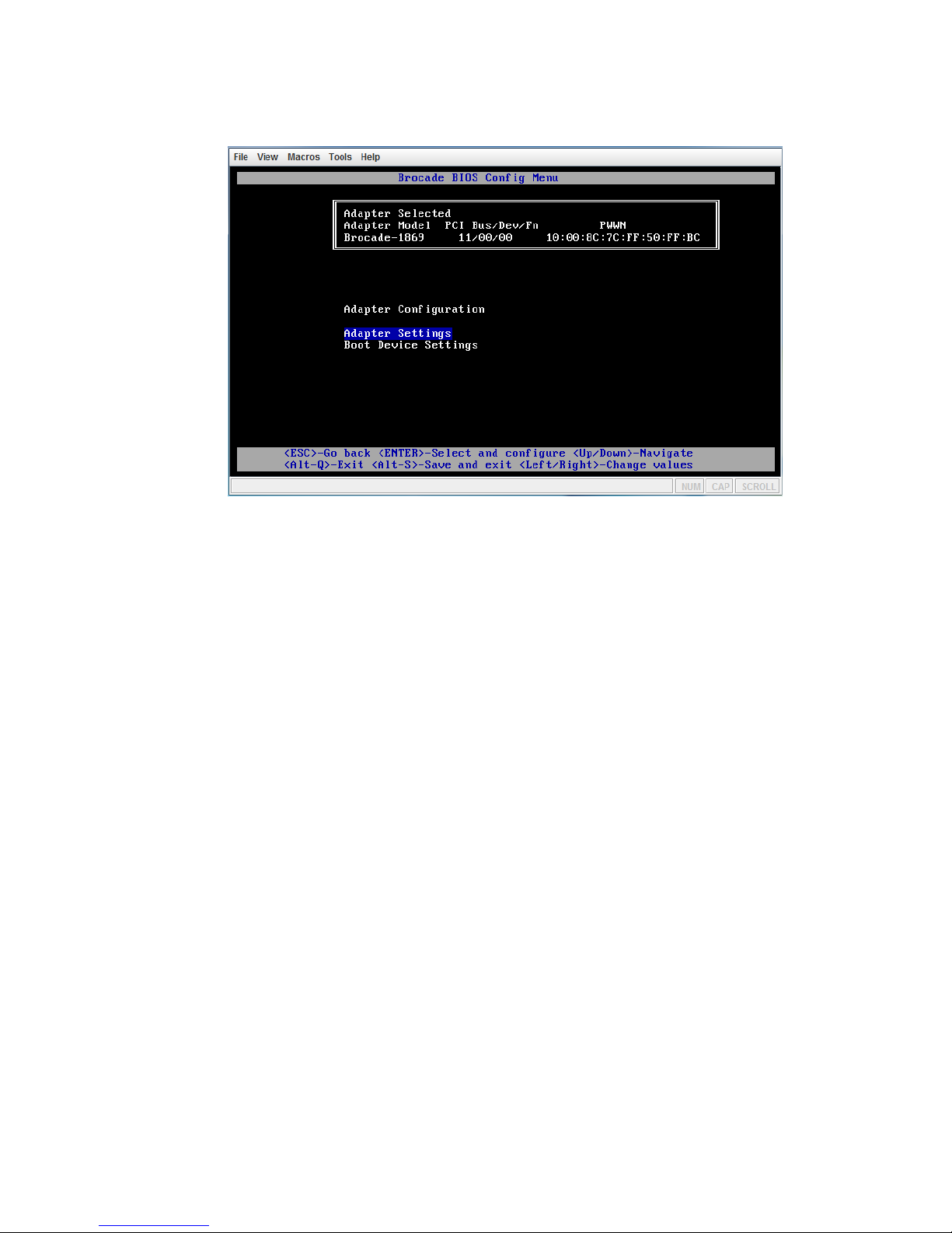
Using the Brocade BIOS Configuration Utility
FIGURE 2 BIOS Configuration Menu (Adapter Configuration)
A
4. Select one of the following:
• Adapter Settings. Use the Adapter Settings screen to enable BIOS, adapter port speed (HBAs
and Fabric Adapter ports configured in HBA mode only), and discovery of boot LUN
information from the fabric. You can determine adapter N and PWWN. Proceed to step 5.
• Boot Device Settings. Use the Device Settings screen to select the boot target and LUN for
booting the host system. Proceed to step 7.
5. Select Adapter Settings and press Enter to begin adapter configuration.
A screen similar to that shown in Figure 3 on page 36 displays showing the port’s current BIOS
version, NWWN and PWWN. Table 3 on page 36 explains options available for BIOS, port speed,
and boot LUN settings.
Using the BIOS Configuration Utility 35
Page 44

Using the Brocade BIOS Configuration Utility
A
FIGURE 3 BIOS Configuration Menu (Adapter Settings)
-
TABLE 3 Brocade BIOS Configuration Utility field descriptions
Field Description
BIOS Version Displays the Brocade BIOS boot code version installed on the card.
NWWN Displays the port’s Node World-Wide Name.
PWWN Displays the port’s unique Port World-Wide Name.
BIOS The value of BIOS must be Enable for the selected adapter port to support
boot over SAN. If this setting is set to Disable, the system will not boot
from the Fibre Channel disk drives that are connected to the selected
adapter port.
NOTE:The default setting for all adapter ports is Enable.
Port Speed Sets the speed for the adapter port.
NOTE:Auto allows the adapter port to automatically negotiate link speed
with the connected port.
Boot LUN
• Fabric Discovered. When enabled, LUN information, such as the
location of the boot LUN, is provided by the fabric.
• Flash Values. Boot LUN information will be obtained from flash
memory. Note that values are saved to flash when you configure and
save them through the BIOS Configuration Utility and BCU.
• First LUN. The host boots from the first LUN visible to the adapter
that is discovered in the fabric.
NOTE:To boot from direct-attached Fibre Channel targets, you must use
the First LUN or Flash Values options.
NOTE:Fabric-based boot LUN discovery (Fabric Discovered) is not
supported for booting from direct-attached targets.
36 IBM Flex System FC5024D 4-Port 16Gb FC Adapter User’s Guide
Page 45

Using the Brocade BIOS Configuration Utility
-
TABLE 3 Brocade BIOS Configuration Utility field descriptions (Continued)
Bootup Delay You can configure values of 1, 2, 5, and 10 minutes. This adds a delay in
discovering the boot LUN to help compensate for the time it takes storage
systems to boot up. During storage system boot, boot LUNs are not visible
to servers that are also booting up.
Port Topology Set Loop if the port is connecting to storage in a Fibre Channel Arbitrated
Loop (FC-AL) and P2P if the port is connecting to storage in a
point-to-point topology.
LUN Mask Enable or disable LUN masking. LUN masking establishes access control
to shared storage to isolate traffic between different initiators that are zoned
in with the same storage target. For more information on LUN masking,
refer to the LUN Masking paragraph under “Fibre Channel features” on
page 5.
6. Change any parameters by following the instructions at the bottom of the BIOS Configuration
Utility screen. For example, use the following keys to select and change information:
• Up and Down keys - Scroll to a different field.
• Enter - Select a field and configure values.
• Left and Right arrow keys - Change a value.
• Alt - S - Save configuration values to adapter flash memory.
• Alt - Q - Exit the utility.
• Esc - Go back a screen.
• Page Up or Page Down - Go to preceding or next screen.
A
NOTE
To restore factory default settings, press R.
7. To configure boot devices, select Boot Device Settings from the initial menu screen for the adapter
port (step 4) and press Enter to designate a discovered LUN as a boot device.
A list of up to four boot devices displays, showing the PWWN of the storage port and the LUN
number designated as a boot LUN. The first device listed is the primary boot device. The host first
tries to boot from the primary device, and then the succeeding devices in the list. Figure 4 shows an
example of the Boot Devices settings.
Using the BIOS Configuration Utility 37
Page 46

Using the Brocade BIOS Configuration Utility
A
FIGURE 4 BIOS Configuration Menu (Boot Device Settlings)
8. Use the Up and Down arrow keys to select a boot device, and then use one of the following options
to configure boot device settings:
• Press C to clear a selected boot device from the list.
• Press M to manually edit boot device information, and then enter the PWWN and LUN values
for the boot device. Press M to exit.
NOTE
When editing boot device information, you must complete the entire value before pressing M or the
configuration will reset to the previous value. For example, if you edit part of a PWWN, and then
press M, the PWWN will return to the previous value.
• Select a device and press Enter. This displays additional screens that allow you to select
discovered LUNs as boot devices.
If you select a device under Boot Device Settings and press Enter, a screen similar to the one in
Figure 5 on page 39 displays listing all discovered boot targets.
38 IBM Flex System FC5024D 4-Port 16Gb FC Adapter User’s Guide
Page 47

Using the Brocade BIOS Configuration Utility
FIGURE 5 BIOS Configuration Menu (Select Port Target)
A
9. Select a target on which you want to designate a boot LUN and press Enter.
A screen similar to the one in Figure 6 displays listing device information and LUNs visible to the
adapter.
FIGURE 6 BIOS Configuration Menu (Select Boot LUN)
10. Select the LUN on the target device that you want to designate as the boot LUN for the host. This
must be the same LUN that you bind to the adapter port using the storage system’s management or
configuration utility.
Using the BIOS Configuration Utility 39
Page 48

Using UEFI setup screens
A
NOTE
You only need to select the bootable LUN once. After the first boot, the same LUN will be used
until changed through the BIOS Configuration Utility.
11. Press Enter. The selected device will be added to the list of boot devices for the adapter on the Boot
Device Settings screen (Figure 7.)
FIGURE 7 BIOS Configuration Menu (Boot Device Settings)
12. Save or exit the configuration utility.
• To save the configuration, press Alt + S.
• To exit without saving, press the Alt + Q.
Using UEFI setup screens
For UEFI systems or UEFI boot mode, use steps in this section to configure boot over SAN and other
adapter storage functions using your system’s UEFI setup utility Storage menu options. These general
instructions are applicable to IBM host systems. Refer to your system’s documentation or online help
for specific details on using your UEFI setup screens.
NOTE
When you change a setting on a UEFI setup screen, the setting is saved to the adapter whenever you
change to a new screen within the adapter configuration or when you close the utility. Changes are
effective even before you explicitly save them.
1. Power on or reboot the host system.
2. Access your UEFI setup screens by booting the system and pressing the F1 key when prompted for
configuration or setup.
The System Configuration and Boot Management menu displays.
40 IBM Flex System FC5024D 4-Port 16Gb FC Adapter User’s Guide
Page 49

Using UEFI setup screens
A
FIGURE 8 System Configuration and Boot Management screen
3. Select System Settings.
The System Settings screen displays.
FIGURE 9 Systems Settings menu
Using the BIOS Configuration Utility 41
Page 50

Using UEFI setup screens
A
4. Select Storage.
A list of installed adapters and MAC addresses displays.
5. From the list of installed devices, select the adapter and port that you want to configure and press
Enter.
The Adapter Version Data screen displays for the adapter.
6. To enable UEFI for boot over SAN, select Port Enabled. You can select the installation boot file
using system configuration Boot Manager screens.
42 IBM Flex System FC5024D 4-Port 16Gb FC Adapter User’s Guide
Page 51

Using UEFI setup screens
7. Set the Port Speed. The Auto Select option allows the adapter port to automatically negotiate link
speed with the connected port.
8. Set the Port Topology to one of the following:
A
• Loop for Fibre Channel Arbitrated Loop (FC-AL) topology
• P2P for point to point (P2P) topology
9. Enable or disable LUN Mask.
Enable or disable LUN masking. LUN masking establishes access control to shared storage to
isolate traffic between different initiators that are zoned in with the same storage target. For more
information on LUN masking, refer to the LUN Masking paragraph under “Fibre Channel features”
on page 5.
Using the BIOS Configuration Utility 43
Page 52

Using UEFI setup screens
A
44 IBM Flex System FC5024D 4-Port 16Gb FC Adapter User’s Guide
Page 53

Appendix
Getting help and technical assistance
Before you call
B
©Copyright IBM Corp. 2013 45
Page 54

Using the documentation
B
Using the documentation
Getting help and information from the World Wide Web
Software service and support
Hardware service and support
46 IBM Flex System FC5024D 4-Port 16Gb FC Adapter User’s Guide
Page 55

IBM Taiwan product service
IBM Taiwan product service
B
Getting help and technical assistance 47
Page 56

IBM Taiwan product service
B
48 IBM Flex System FC5024D 4-Port 16Gb FC Adapter User’s Guide
Page 57

Appendix
Notices
C
©Copyright IBM Corp. 2013 49
Page 58

Trademarks
C
Trademarks
IBM, the IBM logo, and ibm.com are trademarks of International
Business Machines Corp., registered in many jurisdictions worldwide.
Other product and service names might be trademarks of IBM or other
companies. A current list of IBM trademarks is available on the web at
"Copyright and trademark information"
at http://www.ibm.com/legal/copytrade.shtml
Adobe and PostScript are either registered trademarks or trademarks of
Adobe Systems Incorporated in the United States and/or other countries.
Cell Broadband Engine is a trademark of Sony Computer Entertainment, Inc., in the
United States, other countries, or both and is used under license
therefrom.
Intel, Intel Xeon, Itanium, and Pentium are trademarks
or registered trademarks of Intel Corporation or its subsidiaries
in the United States and other countries.
Java and all Java-based trademarks and logos are trademarks or registered
trademarks of Oracle and/or its affiliates.
Linux is a registered trademark of Linus
Torvalds in the United States, other countries, or both.
Microsoft, Windows, and Windows NT are trademarks of Microsoft Corporation in
the United States, other countries, or both.
UNIX is a registered trademark of The Open Group in the United States and other countries.
50 IBM Flex System FC5024D 4-Port 16Gb FC Adapter User’s Guide
Page 59

Important notes
This product is not intended to be connected directly or indirectly by any means
whatsoever to interfaces of public telecommunications networks, nor is it intended
to be used in a public services network.
Important notes
C
Notices 51
Page 60

Electronic emission notices
C
Electronic emission notices
52 IBM Flex System FC5024D 4-Port 16Gb FC Adapter User’s Guide
Page 61

Electronic emission notices
C
European Community contact:
IBM Deutschland GmbH
IBM Technical Regulations, Department M372
IBM-Allee 1,71139 Ehningen, Germany
Telephone: +49 7032 15 2941
Email: lugi@de.ibm.com
Notices 53
Page 62

Electronic emission notices
C
GmbH
Abteilung M372
39
41
lugi
54 IBM Flex System FC5024D 4-Port 16Gb FC Adapter User’s Guide
Page 63

Electronic emission notices
This is electromagnetic wave compatibility equipment
for business (Type A). Sellers and users need to pay
attention to it. This is for any areas other than home.
C
Notices 55
Page 64

Electronic emission notices
C
56 IBM Flex System FC5024D 4-Port 16Gb FC Adapter User’s Guide
Page 65

Index
B
BB credit recovery, 5
BCU, 23
BIOS, 27
configuration, 33
configuring with Brocade BIOS Utility, 19
support, 4
BIOS configuration utility
information, 20
BIOS configuration utility field descriptions, 36
boot code updates, 27
boot code updates with BCU, 28
boot code updates with HCM, 29
boot LUN discovery, 7
boot over SAN, 7
configuring, 33
configuring BIOS, 19
Brocade Adapter Software Installer (BASI)
using for driver packages, 14
Brocade Command Line Utility (BCU), 23
C
diagnostic port, 6
documentation
BCU and HCM, 24
related, 2
driver packages, 13
components, 13
installing with software installer, 16
drivers
update with HCM, 26
E
electronic emission notices
Canada Class A, 52
FCC statement, 52
Germany Class A statement, 54
Japan VCCI statement, 55
KCC statement, 55
People’s Republic of China Class A statement, 55
Russia EMI statement, 55
Taiwan Class A statement, 55
enhanced hibernation support, 6
extended SRB support, 4
calling for service, 45, 46
caution and danger statements, 3
chassis compatibility, 1
command line utility, 23
compliance statement, 52
configuration
BIOS parameters, 33
customizing for the adapter, 19
configuring, 21
adapter, 23
BIOS, 19
credit recovery, 5
D
description of adapter, 1
Index 57
F
FA-PWWN, 6
FC features, 5
FC trunking, 7
FCP-IM I/O profiling, 6
FC-SP, 8
features of adapter, 4
Fibre Channel adapter
host and fabric support, 8
Fibre Channel adapter management
BCU, 23
HCM, 23
FIP support, 9
firmware for adapter CPU, 13
Page 66

H
O
HBA
management applications, 23
throughput per port, 5
HCM, 23
Host Connectivity Manager (HCM)
description, 23
human interaction interface, 4
Hyper-V, 4, 8
I
I/O transfer rates, 10
IBM Flex System FC5024 4-Port 16Gb FC Adapter
boot code, 27
description, 1
FC features, 5
features, specifications, and standards, 4
management using BCU and HCM, 23
protocols supported, 10
specifications, 10
transfer rate, 10
IBM website, 1
installing adapter in chassis, 13
installing adapter in compute node, 13
installing driver package with software installer, 16
interrupt coalescing
FCoE, 6
L
LUN masking, 6, 8
M
MSI-X, 8
OFM-based WWN provisioning, 4
P
PCI boot code for adapters, 27
product description, 1
protocols supported by adapter, 10
Q
quality of service (QoS), 6
R
RoHS-6, 4
S
safety information, iii
service
before you call, 45
IBM Taiwan, 47
SMI-S, 4, 7
software
driver package, 13
installation notes, 14
installing using software installer, 16
software installer, 13
software service and support, 46
specifications of adapter, 4, 10
standards, 4
statements, 3
storage driver, 13
storage drivers, 21
synthetic FC ports, 4
N
N_Port trunking, 7
network boot
configuring with UEFI HII, 40
notices and statements in document, 3
NPIV, 7
58 IBM Flex System FC5024D 4-Port 16Gb FC Adapter User’s Guide
T
Taiwan product service, 47
target rate limiting (TRL), 7
target reset control, 7
Page 67

trunking, 7
U
UCM compliance, 5
UEFI, 27
UEFI support, 4
update drivers with HCM, 26
V
virtual channels per port, 7
W
Windows 2012, 5
Windows 7 driver support, 5
Windows Server 2008, 5
Windows Server Core, 5, 8
WinPE, 5
WMI support, 5
Index 59
Page 68

60 IBM Flex System FC5024D 4-Port 16Gb FC Adapter User’s Guide
Page 69

Page 70

Part Number: 00D2348
Printed in USA
P/N: 00D2348
*00D2348*
 Loading...