

Page 1

IBM Flex System EN2092 1Gb Eth e rnet Scalable Switch
User's Guide
Page 2

Page 3

IBM Flex System EN2092 1Gb Eth e rnet Scalable Switch
User's Guide
Page 4

Note: Before using this information and the product it supports, read the general information in Appendix B, “Notices,” on page
31, the Safety Information and Environmental Notices and User Guide documents on the IBM Notices for Network Devices CD, and the
Warranty Information document that comes with the product.
First Edition, February 2012
© Copyright IBM Corporation 2012.
US Government Users Restricted Rights – Use, duplication or disclosure restricted by GSA ADP Schedule Contract
with IBM Corp.
Page 5

Contents
Safety ....................................v
Safety statements ..................................v
UL Regulatory Information ..............................viii
Chapter 1. The IBM Flex System EN2092 1Gb Ethernet Scalable Switch ........1
Related documentation ................................1
Notices and statements in this document ..........................2
Features and specifications...............................2
Major components of the switch .............................2
Chapter 2. Installing the switch..........................5
Installation guidelines ................................6
System reliability guidelines .............................6
Handling static-sensitive devices............................7
Installing a switch .................................7
Removing or replacing a switch .............................9
Cabling the switch and the SFP+ module .........................10
Connecting the serial console cable ..........................10
Disconnecting the serial console cable .........................10
Connecting the SFP+ module cable ..........................10
Disconnecting the SFP+ module cable .........................11
Connecting the RJ-45 cable .............................11
Disconnecting the RJ-45 cable ............................12
Installing and removing a 10 Gb SFP+ module ......................12
Handling an SFP+ module ............................12
Installing an SFP+ module ............................13
Removing an SFP+ module ............................14
Locating the information panels, LEDs, and external ports....................14
Information panel ................................15
Information LEDs ................................16
Switch status LEDs ...............................16
Port status LEDs................................17
Configuring the switch ...............................17
Establishing a TCP/IP session through the management module ................19
Enabling management through external ports .......................19
Configuring the switch through the Telnet interface .....................20
Connecting to the switch .............................20
Accessing the main menu ............................20
Configuring the switch through the serial-port interface ...................21
Configuring the switch through the switch browser-based interface................21
Initial configuration ...............................22
Logging in to the switch ..............................22
Chapter 3. Updating the firmware and licensing ..................23
Determining the level of switch firmware .........................23
Obtaining the latest level of switch firmware ........................23
Upgrading the switch firmware.............................23
Resetting and restarting the switch ...........................24
Acquiring feature licenses ..............................25
Chapter 4. Solving problems ..........................27
Running POST ..................................27
POST errors ...................................27
Parts listing ...................................28
© Copyright IBM Corp. 2012 iii
Page 6

Appendix A. Getting help and technical assistance ................29
Before you call ..................................29
Using the documentation ...............................29
Getting help and information from the World Wide Web ....................29
Software service and support .............................30
Hardware service and support .............................30
IBM Taiwan product service ..............................30
Appendix B. Notices ..............................31
Trademarks ...................................32
Important notes ..................................32
Documentation format................................33
Electronic emission notices ..............................33
Index ....................................37
iv
1Gb Ethernet Scalable Switch: User's Guide
Page 7

Safety
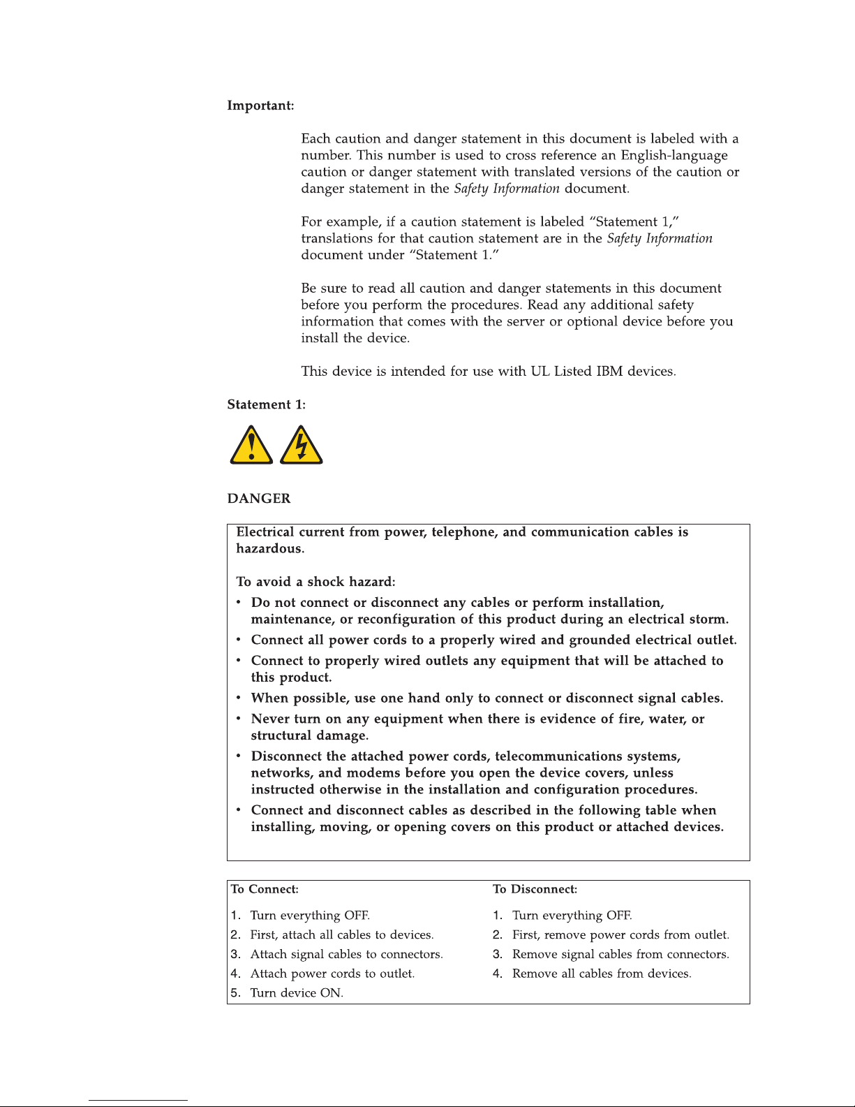
Safety statements
© Copyright IBM Corp. 2012 v
Page 8
vi 1Gb Ethernet Scalable Switch: User's Guide
Page 9
Safety vii
Page 10

UL Regulatory Information
This device is for use only with Listed IBM Flex System Enterprise Chassis.
viii 1Gb Ethernet Scalable Switch: User's Guide
Page 11

Chapter 1. The IBM Flex System EN2092 1Gb Ethernet
Scalable Switch
The EN2092 1Gb Ethernet scalable switch provides support for L2/L3 switching
and routing. This switch has passed IPv6 USGv6 certification, so it also can
support IPv6 functions.
The base model of the EN2092 switch supports 24Gb full-duplex throughput with
fourteen 1Gb ports down and ten RJ-45 1Gb ports up. With the optional upgrades,
you easily and cost-effectively can scale this switch to support 48Gb full-duplex
throughput with twenty eight 1Gb ports down and twenty RJ-45 1Gb ports up, or
88Gb full-duplex throughput with twenty eight 1Gb ports down, twenty RJ-45 1Gb
ports up, and four 1Gb/10 Gb SFP+ uplink ports up.
This User's Guide contains information and instructions for installing the switch,
updating the firmware, and solving problems.
For information about the types of compatible devices available for IBM products,
contact your IBM marketing representative or authorized reseller. For a list of
supported optional devices, see http://www.ibm.com/servers/eserver/
serverproven/compat/us/.
You can obtain up-to-date information about the switch at http://www.ibm.com/
supportportal/.
Notes:
1. The illustrations in this document might differ slightly from your hardware.
2. The screens that are described or referenced in this document might differ
slightly from the screens that are displayed by your system. Screen content
varies according to the type of IBM chassis and the firmware versions and
options that are installed.
Related documentation
This User's Guide contains setup and installation instructions for the switch and
general information about the switch, including how to configure, update, and
troubleshoot the switch, and how to get help. The most recent version of this
User's Guide and all other related documents are at http://
publib.boulder.ibm.com/infocenter/flexsys/information/index.jsp
The following related documentation is available at http://www.ibm.com/
supportportal/:
v IBM Flex System EN2092 1Gb Ethernet Scalable Switch Application Guide
v IBM Flex System EN2092 1Gb Ethernet Scalable Switch Menu-Based CLI Command
Reference
v IBM Flex System EN2092 1Gb Ethernet Scalable Switch ISCLI–Industry Standard CLI
Command Reference
v IBM Flex System EN2092 1Gb Ethernet Scalable Switch BBI Quick Guide
v IBM Flex System Network Devices Basic Troubleshooting Information
© Copyright IBM Corp. 2012 1
Page 12

Notices and statements in this document
Features and specifications
Notices for Network Device
For detailed information about the switch hardware and firmware features,
specifications, and standards, see the switch Application Guide.
Major components of the switch
The switch has the following components:
v The base model of the EN2092 1Gb Ethernet scalable switch supports 24Gb
full-duplex throughput with fourteen 1Gb ports down and ten RJ-45 1Gb ports
up.
v With the optional upgrades, you easily and cost-effectively can scale this switch
to support 48Gb full-duplex throughput with twenty eight 1Gb ports down and
twenty RJ-45 1Gb ports up, or 88Gb full-duplex throughput with twenty eight
1Gb ports down, twenty RJ-45 1Gb ports up, and four 1Gb/10Gb SFP+ uplink
ports up. See “Acquiring feature licenses” on page 25 for information on how to
upgrade the switch with optional licenses.
You can manage and configure the switch through the following interfaces:
v A SSHv2/Telnet connection to the embedded command-line interface (CLI)
v A terminal emulation program connection to the serial port interface
v A Web browser-based interface (https/http) connection to the switch
Record information about the switch in the following table. The product name and
serial number are on the identification label on the sides of the switch. The media
access control (MAC) address is on a separate label. You will need this information
when you register the switch with IBM
http://www.ibm.com/support/mysupport/.
®
. You can register the switch at
2 1Gb Ethernet Scalable Switch: User's Guide
Page 13

Product name IBM Flex System EN2092 1Gb Ethernet Scalable Switch
Model number _____________________________________________
Serial number _____________________________________________
Part number _____________________________________________
Media access control (MAC)
_____________________________________________
address for switch
MAC addresses for other
_____________________________________________
components
_____________________________________________
_____________________________________________
Chapter 1. The IBM Flex System EN2092 1Gb Ethernet Scalable Switch 3
Page 14

4 1Gb Ethernet Scalable Switch: User's Guide
Page 15

Chapter 2. Installing the switch
This chapter provides instructions for installing a switch in the IBM Flex System
chassis and for removing a switch from the IBM Flex System chassis. See the
documentation for your IBM Flex System chassis for information about I/O bay
locations and the components that can be installed in them that is specific to your
IBM Flex System chassis type.
You can install up to four I/O modules in the IBM Flex System chassis, including
Ethernet switch modules, Fibre Channel switch modules, Infiniband, and pass-thru
modules (optical and copper).
The following illustration shows an example of a IBM Flex System chassis with the
I/O bays identified.
I/O module
bay 1
I/O module
bay 3
I/O module
bay 2
I/O module
bay 4
To enable the switch to communicate with a compute node, at least one switch
must be installed in the IBM Flex System chassis. For details about network
adapter installation, configuration, and use, see the documentation that comes with
the network adapter.
Installing a second switch enables a redundant path and a separate connection
from the compute node to the external Ethernet network.
The IBM Flex System chassis supports a maximum of four IBM Flex System
EN2092 1Gb Ethernet Scalable Switch Modules. Depending on the type of IBM
Flex System chassis that you are using, the IBM Flex System chassis supports a
maximum of 10 or 14 network adapters.
Notes:
© Copyright IBM Corp. 2012 5
Page 16

v I/O bays 1 and 2 support any standard Ethernet switch or pass-thru modules
that connects to the two integrated Ethernet controllers in each of the compute
nodes. When you install an adapter card in the first bay on the compute node,
the I/O bays support any switch with the same type of network interface that is
used in the corresponding compute node adapter bay.
v The I/O bays 3 and 4 support Ethernet switch modules, Fibre Channel switch
modules, Infiniband, and pass-thru modules (optical and copper) if the serial
pass-thru modules are not being used. If you install an additional I/O module in
bay 3 or 4, a corresponding adapter card is required to be installed in each
compute node to access the I/O bay.
v The compute nodes or IBM Flex System chassis that are described or shown in
this document might be different from your compute nodes or IBM Flex System
chassis. For additional information, see the documentation that comes with your
compute node or IBM Flex System chassis.
v When the switch is installed in a IBM Flex System chassis, the internal ports
operate at 10 Gbps or 1 Gbps. The external ports can operate at 10 Gbps or 1
Gbps, depending on the SFP module type.
Installation guidelines
Before you install the switch in the IBM Flex System chassis, read the following
information:
v Read the safety information that begins on page v, “Handling static-sensitive
devices” on page 7, and the safety statements in the IBM Flex System chassis
documentation. This information provides a safe working environment.
v Observe good housekeeping in the area where you are working. Place removed
covers and other parts in a safe place.
v Blue on a component indicates touch points, where you can grip the component
to remove it from or install it in the blade server or IBM Flex System chassis,
open or close a latch, and so on.
v Orange on a component or an orange label on or near a component on the
switch, blade server, or IBM Flex System chassis indicates that the component
can be hot-swapped, which means that if the IBM Flex System chassis and
operating system support hot-swap capability, you can remove or install the
component while the IBM Flex System chassis is running. (Orange can also
indicate touch points on hot-swap components.) See the instructions for
removing or installing a specific hot-swap component for any additional
procedures that you might have to perform before you remove or install the
component.
v You do not have to turn off the IBM Flex System chassis to install or replace any
of the hot-swap modules on the front or rear of the IBM Flex System chassis.
v When you install a switch in the IBM Flex System chassis, you must also install
a compatible I/O expansion card in the blade server to support the switch.
v When you are finished working on the blade server or IBM Flex System chassis,
reinstall all safety shields, guards, labels, and ground wires.
v For a list of supported optional devices for the IBM Flex System chassis and
other IBM products, see http://www.ibm.com/servers/eserver/serverproven/
compat/us/.
System reliability guidelines
To help ensure proper cooling, performance, and system reliability, make sure that
the following requirements are met:
6 1Gb Ethernet Scalable Switch: User's Guide
Page 17

v Each of the module bays on the rear of the IBM Flex System chassis contains
either a module or a filler module.
v A removed hot-swap module is replaced with an identical module or filler
module within 1 minute of removal.
v A removed hot-swap compute node is replaced with another compute node or
filler node within 1 minute of removal.
v The ventilation areas on the sides of the compute node are not blocked.
v You have followed the reliability guidelines in the documentation that comes
with the IBM Flex System chassis.
Cable requirements for the switch are described in the IBM Configuration and
Options Guide at http://www.ibm.com/servers/eserver/xseries/cog/. See the
documentation that comes with the IBM Flex System chassis for cable-routing
information.
Handling static-sensitive devices
Attention: Static electricity can damage the IBM Flex System chassis and other
electronic devices. To avoid damage, keep static-sensitive devices in their
static-protective packages until you are ready to install them.
To reduce the possibility of electrostatic discharge, observe the following
precautions:
v Limit your movement. Movement can cause static electricity to build up around
you.
v Handle the device carefully, holding it by its edges or its frame.
v Do not touch solder joints, pins, or exposed printed circuitry.
v Do not leave the device where others can handle and damage it.
v While the device is still in its static-protective package, touch it to an unpainted
metal surface of the IBM Flex System chassis or an unpainted metal surface on
any other grounded rack component in the rack that you are installing the
device in for at least 2 seconds. This drains static electricity from the package
and from your body.
v Remove the device from its package and install it directly into the IBM Flex
System chassis without setting down the device. If it is necessary to set down
the device, put it back into its static-protective package. Do not place the device
on the IBM Flex System chassis or on a metal surface.
v Take additional care when you handle devices during cold weather. Heating
reduces indoor humidity and increases static electricity.
v Some types of IBM Flex System chassis come with electrostatic discharge (ESD)
connectors. If your unit is equipped with an ESD connector, see the
documentation that comes with the IBM Flex System chassis for using the ESD
connector.
Installing a switch
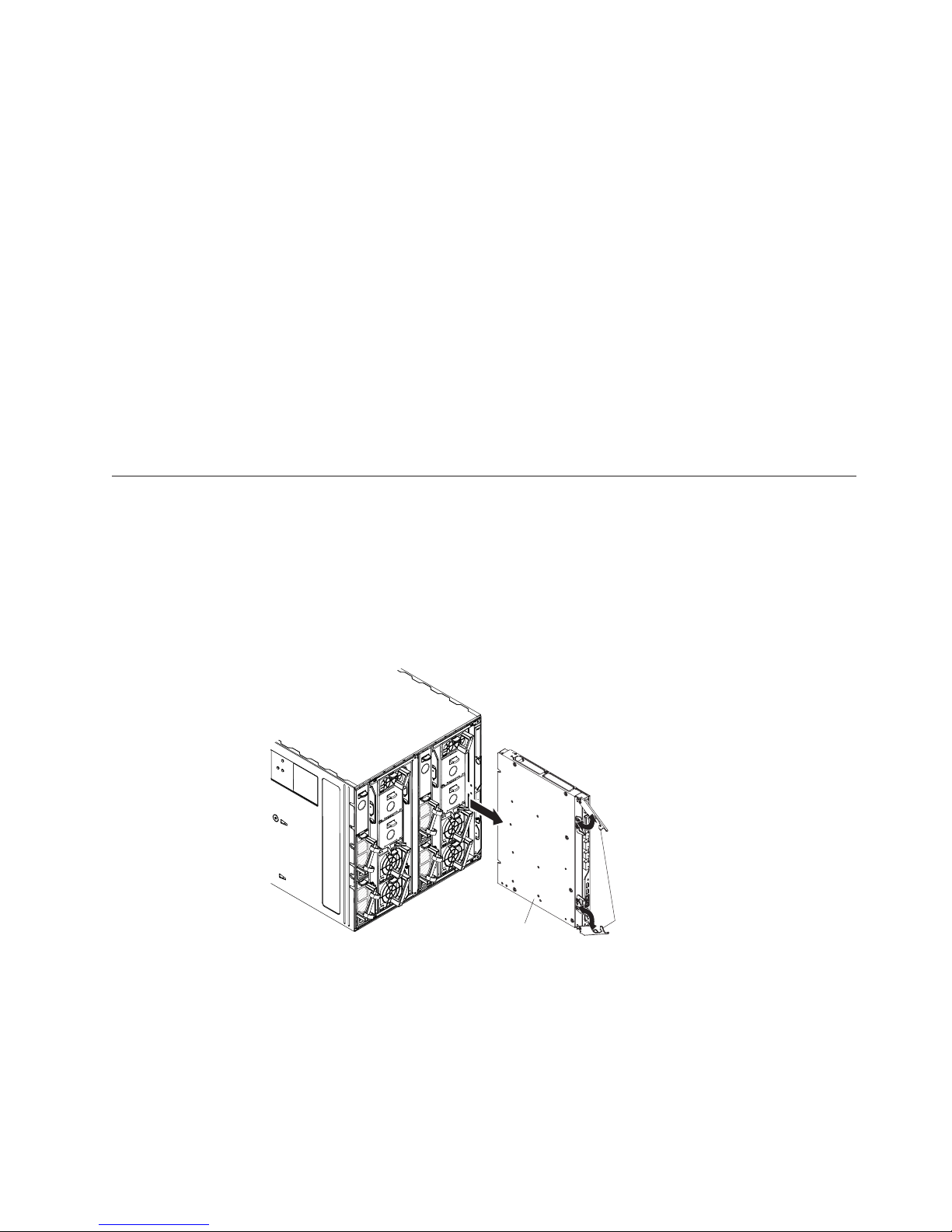
Note: The following illustration shows how to install a switch in a IBM Flex
System chassis. The appearance of your IBM Flex System chassis might be
different; see the documentation for your IBM Flex System chassis for
additional information.
Chapter 2. Installing the switch 7
Page 18

Use the following instructions to install a switch in the IBM Flex System chassis.
You can install a switch while the IBM Flex System chassis is powered on. For
redundancy support, you must install I/O modules of the same type in I/O bays 1
and 2, and I/O modules of the same type in bays 3 and 4 of the chassis.
To install a switch, complete the following steps:
1. Read the safety information that begins on page v and “Installation
guidelines” on page 6.
2. Verify that the switch is compatible with the chassis. For a list of supported
optional devices for the IBM Flex System chassis and other IBM products, see
http://www.ibm.com/servers/eserver/serverproven/compat/us/.
3. Select I/O bay in which to install the switch.
Note: For details about I/O bay requirements and bay locations, see the
documentation for the IBM Flex System chassis and compute nodes.
4. Remove the filler module from the selected bay. Store the filler module for
future use.
5. If you have not already done so, touch the static-protective package that
contains the switch to an unpainted metal surface of the IBM Flex System
chassis or an unpainted metal surface on any other grounded rack-component
for at least 2 seconds.
6. If the removed filler module (from step 4) occupied two bays:
v Remove the single-high filler module from its static-protective package.
v Install the single-high filler module into the unused bay.
7. Remove the switch from its static-protective package.
8. Make sure that the release levers on the switch are in the open position
(perpendicular to the switch).
9. Slide the switch into the applicable I/O-module bay until it stops.
10. Push the release levers on the front of the switch to the closed position. After
you insert and lock the switch, it is turned on, and a power-on self-test
(POST) occurs to verify that the switch is operating correctly.
Notes:
a. The switch takes approximately 60 seconds to complete the POST. When
the switch is turned on, an LED test occurs. All LEDs are lit and remain lit
during POST; then, all the LEDs except the OK LED turn off. This
indicates normal POST results.
8 1Gb Ethernet Scalable Switch: User's Guide
Page 19
b. To maintain proper airflow, make sure that the ventilation holes on the
front of the switch are not blocked.
11. Make sure that the LEDs on the switch indicate that it is operating correctly
(see “Information LEDs” on page 16).
12. If you have another switch to install, repeat step 4 on page 8 through step 11;
otherwise, go to the next step.
13. Install the SFP+ modules in the switch. For information and instructions, see
“Installing and removing a 10 Gb SFP+ module” on page 12 and the
documentation that comes with the SFP+ module.
14. Attach any cables that are required by the switch. For additional information
about cabling the switch, see “Cabling the switch and the SFP+ module” on
page 10, the documentation that comes with the cables, and the optional
network devices to which the cables have been connected. For the locations of
the connectors on the IBM Flex System chassis, see the documentation that
comes with the IBM Flex System chassis. Then, continue with the next step.
15. Make sure that the external ports on the switch are enabled through one of
the management-module interfaces, such as the Web-based interface or the
CLI.
Removing or replacing a switch
Note: The following illustration shows how to remove and replace a switch from a
IBM Flex System chassis. The appearance of your IBM Flex System chassis
might be different; see the documentation for your IBM Flex System chassis
for additional information.
To replace a switch, complete the following steps:
I/O module
Handles
1. Read the safety information that begins on page v, and “Installation guidelines”
on page 6.
2. Disconnect any cables from the switch that you are removing. Removing these
cables (especially an Ethernet cable) disrupts the network connection from the
external Ethernet port to any connected external Ethernet devices. If you plan
to replace the switch with another switch, you can use the existing Ethernet
cable, provided that it remains securely attached to the Ethernet network. For
additional information about cabling the switch, see “Cabling the switch and
the SFP+ module” on page 10, the documentation that comes with the cables,
and the optional network devices to which the cables have been connected. For
Chapter 2. Installing the switch 9
Page 20

the locations of the connectors on the IBM Flex System chassis, see the
documentation that comes with the IBM Flex System chassis. Then, continue
with step 3.
3. Pull the release latches out from the switch. The switch moves out of the bay
approximately 0.6 cm (0.25 inch).
4. Slide the switch out of the bay and set it aside.
5. Place either another switch or a filler module in the bay.
Important: Complete this step within 1 minute. (For more information, see
steps 10 and 11 on page 9.)
6. If you placed a filler module in the bay, continue with “Installing and removing
a 10 Gb SFP+ module” on page 12.
7. If you placed a switch in the bay, reconnect the other cables that you
disconnected. Attach any additional cables that are required by the switch. For
additional information about cabling the switch, see “Cabling the switch and
the SFP+ module,” the documentation that comes with the cables, and the
optional network devices to which the cables have been connected. For the
locations of the connectors on the IBM Flex System chassis, see the
documentation that comes with the IBM Flex System chassis. Then, continue
with “Installing and removing a 10 Gb SFP+ module” on page 12.
Cabling the switch and the SFP+ module
This section describes how to cable the switch and its optional devices.
The supported SFP+ modules and DAC cables for the switch are as follows:
v 10GBase-SR SFP+ (MMFiber) transceiver (part no. 44W4408)
v 10GBase-SR SFP+ (MMFiber) transceiver (part no. 46C3447)
v IBM BNT SFP+ LR transceiver (part no. 90Y9412)
v 1000Base-SX SFP (MMFiber) transceiver (part no. 81Y1622)
v 1000Base-T SFP transceiver 4 (part no. 81Y1618)
v 1000Base-LX SFP LX transceiver (part no. 90Y9424)
v 1m IBM Passive DAC SFP+ (part no. 90Y9427)
v 3m IBM Passive DAC SFP+ (part no. 90Y9430)
v 5m IBM Passive DAC SFP+ (part no. 90Y9433)
Note: The illustrations in this document might differ slightly from your hardware.
Connecting the serial console cable
To connect the serial console cable to the switch, connect the serial cable to the
mini-USB serial console port of the switch and the other end of the cable to the
console device.
Disconnecting the serial console cable
To disconnect the serial console cable, grasp the connector and gently pull the
cable from the switch.
Connecting the SFP+ module cable
Attention: To avoid damage to the fiber optic cables, follow these guidelines:
v Do not route the cable along a folding cable-management arm.
10 1Gb Ethernet Scalable Switch: User's Guide
Page 21

v When you attach the cable to a device on slide rails, leave enough slack in the
cable so that it does not bend to a radius of less than 38 mm (1.5 in.) when the
device is extended or become pinched when the device is retracted.
v Route the cable away from places where it can be snagged by other devices in
the rack.
v Do not overtighten the cable straps or bend the cables to a radius of less than 38
mm (1.5 in.).
v Do not put excess weight on the cable at the connection point. Make sure that
the cable is well supported.
To connect the SFP+ module cable, complete the following steps:
1. Remove the protective caps from the end of the fiber optic cable.
Fiber-optic
cable
Protective cap
2. Gently slide the fiber optic cable into the SFP+ module until it clicks into place.
3. Check the LEDs on the switch. When the switch is operating correctly, the
green link LED is lit. For information about the status of the switch LEDs, see
“Locating the information panels, LEDs, and external ports” on page 14.
Disconnecting the SFP+ module cable
To disconnect the SFP+ module cable, complete the following steps:
1. Squeeze the release tabs and gently pull the fiber optic cable from the SFP+
module.
2. Replace the protective caps on the ends of the fiber optic cable.
Connecting the RJ-45 cable
To connect the RJ-45 connector to the switch, push the RJ-45 cable connector into
the port connector until it clicks into place.
Chapter 2. Installing the switch 11
Page 22

Disconnecting the RJ-45 cable
To disconnect the RJ-45 connector, squeeze the release tab and gently pull the cable
connector out of the switch-module connector.
Installing and removing a 10 Gb SFP+ module
The switch supports the 10 Gb small-form-factor pluggable (SFP+) module and the
1 Gb small-form-factor pluggable (SFP) module. The SFP+ and SFP modules are
laser products that convert electrical signals to optical signals.
For additional information about the location of the switch, the network interface
requirements, and expansion options, see the documentation for your IBM Flex
System chassis.
Notes:
1. The illustrations in this document might differ slightly from your hardware.
2. While the information in this section describes the 10 Gb small-form-factor
pluggable (SFP+) module, it also applies to the 1 Gb small-form-factor
pluggable (SFP) module.
3. The switch also supports MSA-compliant copper direct-attach cables (DAC), up
to 7 m (23 ft) in length.
Handling an SFP+ module
Before you install an SFP+ module, read the following information:
v The module housing of the SFP+ has an integral guide key that is designed to
prevent you from inserting the module incorrectly.
v Use minimal pressure when you insert the module into the port. Forcing the
module into the port can cause damage to the module or the module port.
v You can insert or remove the module while the IBM Flex System chassis is
turned on.
v You must first insert the module into the port before you can connect the cables.
v You must remove the cable from the SFP+ module before you remove the SFP+
module from the switch.
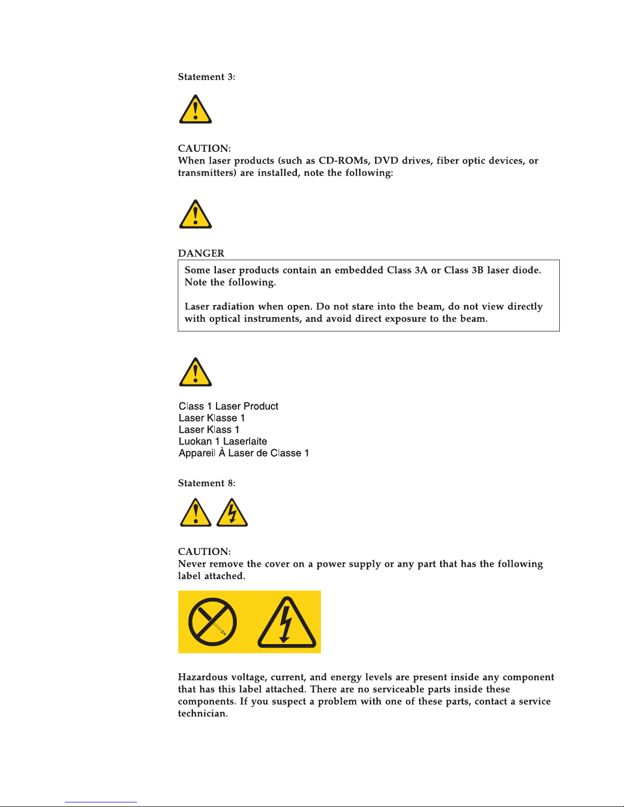
Statement 3:
12 1Gb Ethernet Scalable Switch: User's Guide
Page 23
CAUTION:
When laser products (such as CD-ROMs, DVD drives, fiber optic devices, or
transmitters) are installed, note the following:
– Do not remove the covers. Removing the covers of the laser product could
result in exposure to hazardous laser radiation. There are no serviceable
parts inside the device.
– Use of controls or adjustments or performance of procedures other than
those specified herein might result in hazardous radiation exposure.
DANGER
Some laser products contain an embedded Class 3A or Class 3B laser diode.
Note the following.
Laser radiation when open. Do not stare into the beam, do not view
directly with optical instruments, and avoid direct exposure to the beam.
Class 1 Laser Product
Laser Klasse 1
Laser Klass 1
Luokan 1 Laserlaite
Appareil A Laser de Classe 1
`
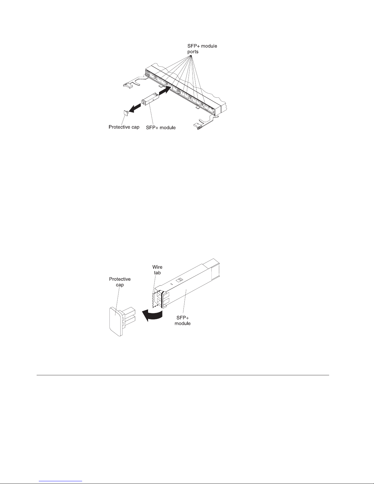
Installing an SFP+ module
The SFP+ module provides two fiber-optic cable connectors for connecting to
external ports. To install an SFP+ module, complete the following steps:
1. Read the safety information that begins on page v and “Installation guidelines”
on page 6.
2. If you have not already done so, touch the static-protective package that
contains the SFP+ module to an unpainted metal surface of the IBM Flex System
chassis or an unpainted metal surface on any other grounded rack component in
the rack in which you are installing the switch for at least 2 seconds.
3. Read the information in “Handling an SFP+ module” on page 12.
4. Remove the SFP+ module from its static-protective package.
5. Remove the protective cap, if one is installed, from the SFP+ module port
where you are installing the SFP+ module and store it in a safe place.
6. Remove the protective cap from the SFP+ module and store it in a safe place.
Attention: To avoid damage to the cable or the SFP+ module, make sure that
you do not connect the fiber optic cable before you install the SFP+ module.
7. Insert the SFP+ module into the SFP+ module port until it clicks into place.
Chapter 2. Installing the switch 13
Page 24
8. Connect the fiber optic cable (see “Connecting the SFP+ module cable” on page
10) and any cables that you disconnected earlier.
Removing an SFP+ module
To remove an SFP+ module, complete the following steps:
1. Read the safety information that begins on page v and “Installation guidelines”
on page 6.
2. Read the information in “Handling an SFP+ module” on page 12.
3. Remove the fiber optic cable from the SFP+ module that you want to replace.
For more information about removing the cable, see “Disconnecting the SFP+
module cable” on page 11.
Attention: To avoid damage to the cable or the SFP+ module, make sure that
you disconnect the fiber-optic cable before you remove the SFP+ module.
4. Unlock the SFP+ module by pulling the wire tab straight out, as shown in the
following illustration.
5. Grasp the wire tab on the SFP+ module and pull it out of the port.
6. Replace the protective cap on the SFP+ module and the SFP+ module port.
7. Place the SFP+ module into a static-protective package.
Locating the information panels, LEDs, and external ports
This section describes the information panels and LEDs on the switch and
identifies the external ports on the information panels.
Note: The illustrations in this document might differ slightly from your hardware.
14 1Gb Ethernet Scalable Switch: User's Guide
Page 25

Information panel
The front panel of the switch contains information LEDs, four SFP+ module port
connectors, one mini-USB serial port connector, and twenty RJ-45 ports.
The switch-module information panel contains the following components:
Chapter 2. Installing the switch 15
Page 26

v LEDs that display the following information:
– The status of the switch and its network connection
– The status of the external connections to the switch
For further details about LEDs, see “Information LEDs.”
v Four SFP+ port connectors to attach SFP+ modules and twenty RJ-45 ports.
v One mini-USB serial port connector for console port use (management purposes)
only. Do not attach any devices to this connector other than the serial cable that
comes with the switch, as described in “Cabling the switch and the SFP+
module” on page 10.
Information LEDs
The front panel of the switch has two sets of LEDs. The OK and switch error LEDs
in the first column at the bottom of the switch indicate the switch status. The link
(LINK) and activity (TX/RX) LEDs indicate the status of the external ports. .
Notes:
v A yellow LED on the IBM Flex System chassis is lit when a system error or
event has occurred. To identify the error or event, check the IBM Flex System
management-module event log or the switch system log.
v An LED test occurs whenever the switch is turned on. All LEDs are lit and
remain lit during POST, and then all the LEDs except the OK LED turn off.
Any errors that are detected during POST are written to the system log. For
information about the command to read the system log, see the IBM Command
Reference for the switch.
When POST errors are written to the system log, these errors are also written to
the IBM Flex System management-module event log. If a hardware error, such as a
current fault occurs, the management module displays it. If a firmware error
occurs, the management module displays the Module did not complete POST
message and a post error code that indicates the test that was running when the
error was detected.
Note: You can also use the management module to make sure that the switch is
operating correctly. For more information, see the documentation for the
IBM Flex System chassis.
Switch status LEDs
The following table provides descriptions of the switch status LEDs on the front
panel of the switch.
Table 1. Switch status LEDs
Status LED Description
OK (
) LED
This green LED is at the bottom of the switch on the front panel.
v When this LED is lit, it indicates that the switch is on.
v When this LED is not lit and the yellow switch error LED is lit, it
indicates a critical alert. If the yellow LED is also not lit, it
indicates that the switch is off.
16 1Gb Ethernet Scalable Switch: User's Guide
Page 27

Table 1. Switch status LEDs (continued)
Status LED Description
Switch error (!) LED This yellow LED is at the bottom of the switch on the front panel.
v When this LED is lit, it indicates a POST failure or critical alert.
Note: When this LED is lit, the system-error LED on the IBM Flex
System chassis is also lit.
v When this LED is not lit and the green LED is lit, it indicates that
the switch is working correctly. If the green LED is also not lit, it
indicates that the switch is off.
Port status LEDs
The following table provides descriptions of the port status LEDs on the front
panel of the switch.
Table 2. Port status LEDs
Status LED Description
Link LED This green LED indicates whether the port link is up or down.
v When this LED is lit, there is an active connection (or link)
between the corresponding port and the device that is using this
connection.
v When this LED is not lit, it indicates that there is no signal on the
corresponding port, or the link is down.
Activity (TX/RX)
LED
This yellow LED indicates the status of the link activity for the port.
v When this LED is flashing or lit, the corresponding port is
connected and online, and link activity is occurring on that port.
v When this LED is not lit, it indicates that there is no signal or no
link activity on the corresponding port.
Configuring the switch
The switch has an internal Ethernet path to the management module, 24 external
Ethernet ports, and a serial console port. The switch supports two remote-access
modes for management through Ethernet connections. You can select the mode
that is best suited for your IBM Flex System environment.
v Default mode: The default mode uses the internal path to the management
module only. In this mode, the remote-access link to the management console
must be attached to the Ethernet connector on the management module. The
Internet protocol (IP) addresses and SNMP parameters of the switches can be
automatically assigned by the IBM Director Flex System Deployment wizard
(when available), or you must assign them through the IBM Flex System
Management and Configuration program. This mode enables you to provide a
secure LAN for management of the IBM Flex Systems subsystems that is
separate from the data network. See “Establishing a TCP/IP session through the
management module” on page 19 for more information.
v Remote management mode: You can enable remote management of the switch
through the external ports, instead of or in addition to access through the
management module. This mode can be enabled only through the
management-module configuration interface. When this mode is enabled, the
twenty external RJ-45 ports and the four external SFP+ ports support both
management traffic and IBM Flex System application data traffic.
This mode enables the use of additional switch IP addresses on different IP
subnets than the management modules. This is useful when the switches are to
Chapter 2. Installing the switch 17
Page 28

be managed and controlled as part of the overall network infrastructure, while
secure management of other IBM Flex System subsystems is maintained through
the management module. See “Enabling management through external ports” on
page 19 for additional instructions about configuring the switch for this mode of
operation.
The mini-USB console port provides an alternative path to manage and configure
the switch for local access.
Important:
v Before you configure the switch, make sure that the management modules in the
IBM Flex System chassis are correctly configured. For more information about
configuring the switch, see the following documents:
– IBM Flex System Advanced Management Module Installation Guide
– IBM Flex System Advanced Management Module User’s Guide
v The default IP address of the switch is 192.168.70.120, 192.168.70.121,
192.168.70.122, or 192.168.70.123, depending on the switch bay where it is
installed.
v If you change the IP address of the switch and restart the IBM Flex System
chassis, the switch maintains this new IP address as its default value.
v The management module and the switch can communicate with each other only
if they are on the same IP subnet.
v When you use the management-module Web interface to update the switch
configuration, the management-module firmware saves the new configuration in
its internal nonvolatile random-access memory (NVRAM). If the switch restarts,
the management module applies the saved configuration to the switch.
If the switch restarts and the management module cannot apply the saved
configuration, the switch defaults to using the configuration that it had
previously saved. If the IP subnet address of the switch does not match the IP
subnet address of the management module, you can no longer manage the
switch from the management module.
v For switch communication with a remote management station, such as an IBM
Director management server, through the management-module external Ethernet
port, the switch internal-network interface and the management-module external
interface must be on the same IP subnet.
For specific details about configuring the switch and preparing for system
installation, see the documentation listed in “Related documentation” on page 1.
Notes:
v Unless otherwise stated, references to the management module apply only to the
IBM Flex System Advanced Management Module, which is the only type of
management module that supports the switch.
v Throughout this document, the management-module Web-based user interface is
also known as the IBM Flex System management-module Web interface.
v Throughout this document, the user name is also known as the login name or
user ID for logging on to interfaces or programs.
v The screens that are described or referenced in this document might differ
slightly from the screens that are displayed by your system. Screen content
varies according to the type of IBM Flex System chassis and the firmware
versions and options that are installed.
18 1Gb Ethernet Scalable Switch: User's Guide
Page 29

Establishing a TCP/IP session through the management
module
To establish a TCP/IP session for the switch through the management module,
complete the following steps:
1. Log on to the management module as described in the User’s Guide or
Command Line Interface Reference Guide for your advanced management module.
If necessary, obtain the IP address of the management module from your
system administrator. The management-module window opens.
Note: The User ID and Password fields are case-sensitive. Type your
information in uppercase letters only. To maintain system security,
change your password after you log on for the first time. The default
User ID is USERID, and the default password is PASSW0RD (where the sixth
character is the number zero, not the letter O).
2. From the I/O Module Tasks menu, click Configuration.
3. In the I/O Module Configuration area, click the bay number that corresponds
to the location of the switch that you installed.
4. In the IP address field in the New Static IP Configuration area, type the new
TCP/IP address of the switch; then, click Save.
Note: The management module does not check for invalid IP addresses.
5. Click Advanced Configuration. You can now start a Web session or a Telnet
session.
The Web interface and the Telnet program provide different ways to access the
same internal-switching firmware and configure it.
v If your system application requires that you use the Web interface program, see
“Configuring the switch through the switch browser-based interface” on page 21
for additional information.
v If your system application requires that you use the Telnet program, see
“Configuring the switch through the Telnet interface” on page 20 for additional
information.
Enabling management through external ports
To access and manage the switch through external interfaces, you must enable the
external ports and the ability to manage the switch through them. Use the
information in the following table to configure your ports.
External management External ports Description
Disabled Disabled The switch must be managed
through the management
module. No traffic is allowed on
external ports.
Disabled Enabled The switch must be managed
through the management
module. Data traffic is allowed
on external ports.
Enabled Disabled The switch can be managed
through the management
module or a blade server. No
traffic is allowed on external
ports.
Chapter 2. Installing the switch 19
Page 30

External management External ports Description
Enabled Enabled The switch can be managed
through the management
module, a blade server, or a
management station that is
connected through an external
port. Data traffic is allowed on
external ports.
To enable management through external ports, complete the following steps:
1. Log on to the management module as described in the User’s Guide or
Command Line Interface Reference Guide for your advanced management module.
If necessary, obtain the IP address of the management module from your
system administrator. The management-module window opens.
2. Click I/O Module Tasks → Configuration and click the bay number that
corresponds to the location of the switch that you installed.
3. Click Advanced Configuration and make sure that external management is
enabled.
4. Click I/O Module Tasks → Admin/Power/Restart and make sure that the
external ports are enabled for the switch that you installed.
Configuring the switch through the Telnet interface
Note: Telnet is disabled by default.
The switch supports a command-line interface (CLI) that you can use to configure
and control the switch over the network through the Telnet program. You can use
the CLI to perform many basic network-management functions. In addition, you
can configure the switch for management through an SNMP-based
network-management system. The following sections describe how to use the
Telnet interface to access the switch, change its settings, and monitor its operation.
Connecting to the switch
If you know the IP address for the switch and you have an existing network
connection, you can use the Telnet program from an external management station
or the management module to access and control the switch. The management
station and the switch must be on the same IP subnet. If you have to obtain the IP
address for the switch or establish a network connection, contact your system or
network administrator. Be sure to use the correct IP address in the required
command, as specified in “Accessing the main menu.”
Accessing the main menu
To connect to the switch through the Telnet interface, complete the following steps:
1. From a DOS command-line prompt, type telnet x and press Enter.
where x is the IP address for the switch.
2. If you do not have an assigned initial password, in the Password field, type the
default password (PASSw0RD, spelled with a zero) and press Enter.
Important: The apply command changes the currently active configuration. If you
want your change to persist beyond the next reboot of the switch, you must enter
the save command. This command stores the current switch configuration and all
changes in nonvolatile memory.
20 1Gb Ethernet Scalable Switch: User's Guide
Page 31

For more information about configuring through the CLI, see the IBM Application
Guide for the switch.
Configuring the switch through the serial-port interface
The mini-USB serial port provides basic communication through a terminal
emulation program (such as Hyperterminal). Because messages from the power-on
self-test (POST) and all initialization information are transmitted through the serial
port, you can use the serial port to log in to the switch and access and configure
the internal switching firmware.
To log in to the switch, complete the following steps:
1. Connect one end of the specifically designed serial cable that comes with your
device into the mini-USB port and connect the other end to the management
station.
For additional information, see “Connecting the serial console cable” on page
10.
2. On the management station, open a console window and make sure that the
serial port is configured with the following settings:
v 9600 baud
v 8 data bits
v No parity
v 1 stop bit
v No flow control
3. Type the user name and password. The default user name is USERID. The
default password is PASSW0RD. The password is spelled with a zero, not the
letter O.
The serial port is compatible with the standard 16550 Universal Asynchronous
Receiver/Transmitter (UART) protocol. The mini-USB serial port is enabled by
default.
Configuring the switch through the switch browser-based
interface
Note: HTTP is disabled by default. HTTPS is not disabled by default.
Before you can access and start the browser-based interface, make sure that you
have completed the following procedures:
v Install the switch in the IBM Flex System chassis.
v Make sure that the switch firmware is installed on the switch.
v Configure at least one IP interface on the switch.
Chapter 2. Installing the switch 21
Page 32

v Enable frames and the JavaScript program in your Web browser.
The following hardware and software are required for the Web interface:
v A frame-capable Web-browser program, such as Internet Explorer (version 6.0 or
later), Mozilla Firefox (version 1.0.4 or later), or Netscape Navigator (version 4.7
or later)
v A computer or workstation with network access to the switch
To start the browser-based interface, complete the following steps:
1. Start a Web browser. The Web-browser window opens.
2. In the URL field, enter the IP address of the switch, in the following format:
http://xxx.xxx.xxx.xxx. The login window opens.
3. Enter the switch user ID and password and click OK. The default user ID is
USERID. The default password is PASSW0RD. The password is spelled with a zero,
not the letter O.
Note: The passwords that are used to access the switch are case-sensitive. To
increase system security, change the password after you log on for the first
time.
Initial configuration
The operating firmware on the switch contains default configuration files that are
installed during the firmware installation. These initial configuration settings are
not in a separate configuration file but are components of the firmware. When you
restore the management module to factory defaults, the original configuration is
restored. For more information about configuring and managing the switch
through the management module, see the Command Reference for the switch.
Logging in to the switch
The switch supports user-based security that enables you to prevent unauthorized
users from accessing the switch or changing its settings.
To log in to the switch, complete the following steps:
1. At the prompt, type your user ID and press Enter. The default user ID is
USERID.
2. Type your password and press Enter. The default password is PASSW0RD. The
password is spelled with a zero, not the letter O. The main-menu window
opens.
After you log on to the switch, you must set the date and time. See the Command
Reference for the switch to perform this task and others as needed.
22 1Gb Ethernet Scalable Switch: User's Guide
Page 33

Chapter 3. Updating the firmware and licensing
This chapter describes how to determine the level of the firmware that is installed
on the switch, how to obtain the latest level of switch firmware, how to upgrade
the firmware, how to acquire additional feature licensing, and how to reset the
switch to activate the firmware upgrade.
Determining the level of switch firmware
After you install the switch in the IBM Flex System chassis, make sure that the
latest firmware is installed on the switch. To determine the level of the firmware
that is installed, complete the following steps:
1. Log on to the management module CLI as described in the switch's User's
Guide or CLI Reference Guide. If necessary, obtain the IP address of the
management module from your system administrator.
2. Set the environment to the bay where you installed the switch. For example:
system> env -T system:switch[1]
3. Issue the info command to display switch firmware information:
system:switch[1]> info
...
Boot ROM
Main application
Main application
Rel date: 01/17/2012
Version: 6.9.1.0
Status: Active
Rel date: 01/17/2012
Version: 6.9.1.0
Status: Active
Rel date: 11/18/2011
Version: 6.9.0.11
Status: Inactive
Obtaining the latest level of switch firmware
The latest firmware update for the IBM Flex System EN2092 1Gb Ethernet Scalable
Switch is available at the following site: http://www.ibm.com/supportportal/
Note: Changes are made periodically to the IBM Web site. The procedure for
locating firmware and documentation might change from what is described
in this document.
Upgrading the switch firmware
You can upgrade the switch firmware by using a TFTP server application.
Typically, this firmware runs as an application under your operating system. Make
sure that this firmware is installed on your server; then, download the firmware
images from http://www.ibm.com/systems/support/ into a directory on your
TFTP server. Enable the TFTP server and set its default directory to the one where
the image is.
To transfer the firmware image files from the TFTP server to the switch, you can
establish a Telnet session through the management module. Ping the TFTP server
to make sure that you have a connection. The Telnet session performs optimally if
© Copyright IBM Corp. 2012 23
Page 34

all three network entities (TFTP server, management module, and switch IP
addresses) are on the same subnet. Otherwise, you must use a router and configure
a gateway address on the switch. Use the management-module interface to
configure the IP addresses of the management module external interface (eth0) and
the switch so that they are both on the same subnet as the TFTP server.
Examples of IP addresses and masks are described in the following table.
Network entity IP address Mask
TFTP server 192.168.2.178 255.255.255.0
Management module (eth0) 192.168.2.237 255.255.255.0
Switch-module current IP
configuration (IF 128)
192.168.2.51 255.255.255.0
Note: With this configuration, you can ping the switch from the TFTP server.
Access the switch command line interface (CLI). Refer to “Configuring the switch
through the Telnet interface” on page 20 for more information.
To upgrade the switch firmware, complete the following steps:
1. Log in to the switch.
2. At the CLI prompt, type the following command and press Enter.
/boot/gtimg imageX TADDR zzzzz
where imagex is the image to install and zzzzz is the operating-system image
file name.
3. At the CLI prompt, type the following command and press Enter.
/boot/gtimg boot TADDR yyyy
Where yyyy is the boot image file name.
4. Press Enter for user name.
5. Enter data path (either mgt or data).
6. Reset and restart the switch as described in “Resetting and restarting the
switch.”
Resetting and restarting the switch
To activate the new image or images, you must reset the switch. To reset the
switch, complete the following steps:
1. Log on to the management module CLI as described in the switch's User's
Guide or CLI Reference Guide. If necessary, obtain the IP address of the
management module from your system administrator.
2. Set the environment to the bay where you installed the switch. For example:
system> env -T system:switch[1]
3. Issue the reset command to restart the switch:
system:mm[1]> env -T system:switch[1]
system:switch[1]> reset
4. Wait approximately 100 seconds for POST to complete.
5. Issue the info command for the switch that was just restarted and note the
corresponding level of the firmware for the switch. Confirm that the firmware
build number reflects the correct firmware release:
24 1Gb Ethernet Scalable Switch: User's Guide
Page 35

system:switch[1]> info
...
Boot ROM
Main application
Main application
Rel date: 11/18/2011
Version: 6.9.0.11
Status: Active
Rel date: 11/18/2011
Version: 6.9.0.11
Status: Active
Rel date: 10/21/2011
Version: 6.8.0.72
Status: Inactive
Acquiring feature licenses
Licenses are available that enable the use of additional ports on the switch:
v Base product: Supports 24Gb full duplex throughput arranged as 14 1Gb ports
down and 10 RJ-451Gb ports up
v Upgrade 1: Supports 48Gb full duplex throughput arranged as 28 1Gb ports
down and 20 RJ-451Gb ports up
v 10Gb uplinks: Supports 88Gb full duplex throughput arranged as 28 1Gb ports
down and 20 RJ-451Gb ports up and four (4) 1Gb/10Gb SFP+ uplink ports up.
The upgrade licenses can be acquired using the IBM System x Features on Demand
website http://www.ibm.com/systems/x/fod/.
You can use the website to perform the following tasks:
v Request a new activation key
v Check an authorization code to see what feature it enables and how many
remaining times it can be used to create a key
v Retrieve the history of feature activation on a selected device
v Retrieve the history of feature activation on a selected authorization code
v Retrieve a lost authorization code
v Manage your IBM customer number
v Find help for the Features on Demand feature activation process
v Provide feedback to IBM about the Features on Demand process
Note: Your IBM ID and password are required to log into the Features on Demand
website. If you are not registered with IBM, go to http://www.ibm.com/
systems/x/fod/ and click My IBM registration in the left navigation pane.
Chapter 3. Updating the firmware and licensing 25
Page 36

26 1Gb Ethernet Scalable Switch: User's Guide
Page 37

Chapter 4. Solving problems
This section provides basic troubleshooting information to help you solve some
problems that might occur while you are setting up the switch. The Application
Guide for the switch provides more details about troubleshooting the switch.
If you cannot locate and correct a problem by using the information in this section,
see Appendix A, “Getting help and technical assistance,” on page 29.
Running POST
To ensure that it is fully operational, the switch processes a series of tests during
power-up or a restart (power-on self-test, or POST). These tests take approximately
1 minute to complete. The management module reads the test results and displays
them for you. During normal operation, these tests are completed without error,
and the green OK LED is lit. However, if the switch fails POST, the yellow switch
error LED and the system-error LED on the IBM Flex System chassis are lit. An
event is stored in the event log in the system status panel of the management
module. The specific failure is displayed on the system status I/O module panel of
the management module.
Note: For the locations and descriptions of the switch LEDs, see “Locating the
information panels, LEDs, and external ports” on page 14.
POST errors
There are two types of errors: noncritical and critical. A noncritical error applies to
one port, and the switch is operational. You can continue to operate the switch;
however, you must replace it as soon as possible. When critical errors occur, the
switch does not operate. To view POST results, complete the following steps:
1. Log on to the management module as described in the IBM Flex System Chassis
Management Module Command-Line Interface Reference Guide. If necessary, obtain
the IP address of the management module from your system administrator. The
login window opens.
2. Turn off the power to the switch; then, turn it on again.
3. After POST is completed, the management module displays the results. Refresh
the window to view the POST results. If a critical error occurs, replace the
switch. If a noncritical error occurs, see the switch error log for additional
details.
The following table describes the basic critical and noncritical failures. This
abbreviated list is representative; it is not an exhaustive list. An error code is
associated with each failure. Error codes are displayed on the Management Module
Switch Information window. Be sure to note the applicable error code and
corresponding failure. You might have to provide this information when you call
for service. For details, see Appendix A, “Getting help and technical assistance,” on
page 29.
Diagnostic indicator (in hex) Failing functional area Failure criticality
00 - 7F Base internal functions Critical
80 - 9F Internal interface failures Noncritical
© Copyright IBM Corp. 2012 27
Page 38

Parts listing
Diagnostic indicator (in hex) Failing functional area Failure criticality
A0 - AF External interface errors Noncritical
B0 - FE Reserved Noncritical
FF Switch “good” indicator Operation
Replaceable components are of three types:
v Tier 1 customer replaceable unit (CRU): Replacement of Tier 1 CRUs is your
responsibility. If IBM installs a Tier 1 CRU at your request, you will be charged
for the installation.
v Tier 2 customer replaceable unit (CRU): You may install a Tier 2 CRU yourself
or request IBM to install it, at no additional charge, under the type of warranty
service that is designated for your server.
v Field replaceable unit (FRU): FRUs must be installed only by trained service
technicians.
For information about the terms of the warranty, see the Warranty Information
document.
The replaceable components in the following table are Tier 1 CRUs. If other IBM
Flex System components require replacement, see the following documentation that
comes with these devices:
v Problem Determination and Service Guide or Hardware Maintenance Manual and
Troubleshooting Guide
v Installation and User’s Guide or Installation Guide
Part CRU number (Tier 1)
IBM Flex System EN2092 1Gb Ethernet Scalable Switch 49Y4296
28 1Gb Ethernet Scalable Switch: User's Guide
Page 39

Appendix A. Getting help and technical assistance
Before you call
Using the documentation
Getting help and information from the World Wide Web
© Copyright IBM Corp. 2012 29
Page 40

Software service and support
Hardware service and support
IBM Taiwan product service
30 1Gb Ethernet Scalable Switch: User's Guide
Page 41

Appendix B. Notices
© Copyright IBM Corp. 2012 31
Page 42

Trademarks
IBM, the IBM logo, and ibm.com are trademarks of International
Business Machines Corp., registered in many jurisdictions worldwide.
Other product and service names might be trademarks of IBM or other
companies. A current list of IBM trademarks is available on the web at
"Copyright and trademark information"
at http://www.ibm.com/legal/copytrade.shtml
Adobe and PostScript are either registered trademarks or trademarks of
Adobe Systems Incorporated in the United States and/or other countries.
Cell Broadband Engine is a trademark of Sony Computer Entertainment, Inc., in the
United States, other countries, or both and is used under license
therefrom.
Intel, Intel Xeon, Itanium, and Pentium are trademarks
or registered trademarks of Intel Corporation or its subsidiaries
in the United States and other countries.
Java and all Java-based trademarks and logos are trademarks or registered
trademarks of Oracle and/or its affiliates.
Linux is a registered trademark of Linus
Torvalds in the United States, other countries, or both.
Important notes
Microsoft, Windows, and Windows NT are trademarks of Microsoft Corporation in
the United States, other countries, or both.
UNIX is a registered trademark of The Open Group in the United States and other countries.
This product is not intended to be connected directly or indirectly by any means
whatsoever to interfaces of public telecommunications networks, nor is it intended
to be used in a public services network.
32 1Gb Ethernet Scalable Switch: User's Guide
Page 43

Documentation format
Electronic emission notices
Appendix B. Notices 33
Page 44

34 1Gb Ethernet Scalable Switch: User's Guide
Page 45

Appendix B. Notices 35
Page 46

This is electromagnetic wave compatibility equipment
for business (Type A). Sellers and users need to pay
attention to it. This is for any areas other than home.
36 1Gb Ethernet Scalable Switch: User's Guide
Page 47

Index
B
bay locations, IBM Flex System chassis 5
blade server
interconnections with expansion card
and high-speed switch-modules 5
C
cables
requirements for Ethernet network 9,
10
requirements for switch modules 7
serial console
installing 10
removing 10
SFP+ module
installing 10
removing 11
cabling
parts listing 28
serial console 10
SFP+ module 11
switch module 10
communication requirements 5, 9
configuration
cable requirements 7
connecting
RJ-45 cable 11
serial console cable 10
SFP+ module cable 11
connecting to the switch module
through the Telnet interface 22
critical errors 27
D
determining the current level of switch
firmware 23
disconnecting
RJ-45 cable 12
serial console cable 10
SFP+ module cable 11
documentation
cable requirements 7
E
enabling management over external
ports 9
enabling the external ports 9
error
critical 27
noncritical 27
Ethernet
network requirements 9, 10
Ethernet switch module
error (!) LED 17
installation guidelines 6
installing 5, 8
Ethernet switch module (continued)
OK LED 16
removing or replacing 9
expansion card
interconnections with blade server
and high-speed switch-modules 5
network requirements 5
external ports
enabling 9
enabling management 9
Ethernet
cable requirements 9, 10
operating speeds on switch 6
F
fiber optic cables
installing 11
removing 11
filler module
installation requirements 8
parts listing 28
firmware updates 23
G
guidelines
handling an SFP+ module 12
handling fiber optic cables 10
handling static-sensitive devices 7
installation 6
system reliability 6
H
handling
an SFP+ module 12
fiber optic cables 10
static-sensitive devices 7
hardware requirements 5
high-speed device interconnections 5
high-speed switch-module (HSSM)
network requirements 5
host channel adapter (HCA)
interconnections with blade server
and high-speed switch-modules 5
internal ports 5
network requirements 5
host channel requirements 5
hot-swap component 6
HSSM (high-speed switch) 5
I
I/O bay locations 5
installation
guidelines 6
procedure
cables 10
installation (continued)
procedure (continued)
cables for switch 9
cables for switch module 10
serial console cable 10
SFP+ module 13
SFP+ module cable 11
switch 8
switch module 8
requirements 5
installing
fiber optic cables 11
high-speed switch 5
options 6, 12
SFP+ module 13
switch 8
switch module 5, 8
internal ports
on Ethernet switch 6
on host channel adapter 5
Internet protocol (IP) address
Telnet program requirements 22
L
LED
critical alert 16, 17
OK 16
switch status 16
switch-module error (!) 17
system status 16
logging in to the switch module
through the Telnet interface 22
login window
Telnet interface 22
M
main menu
Telnet interface 22
N
network requirements 5, 9
noncritical errors 27
notes, important 32
O
obtaining the latest level of switch
firmware 23
OK LED 16
options
installing 6, 12
P
parts listing 28
© Copyright IBM Corp. 2012
37
Page 48

password rules
Telnet interface 20, 22
port fault 17
ports
external
operating speeds on switch 6
internal
on host channel adapter 5
operating speeds on switch 6
power-on self-test (POST)
completed 8
description 8
failure 17
normal 8
switch module
cable requirements 7
cabling 10, 28
external ports
enabling 9
installation guidelines 6
installing 8
parts listing 28
removing or replacing 9
status
switch module 16
switch-module error (!) LED 17
system reliability 6
system-error LED 17
system-status LED 16
R
removing
fiber optic cables 11
serial console cable 10
SFP+ module 14
switch module 9
requirements, hardware 5
resetting the switche 24
restarting the switch 24
RJ-45 cable
connecting 11
disconnecting 12
S
serial console cable
connecting 10
disconnecting 10
parts listing 28
SFP+ module
cable, connecting 11
cable, disconnecting 11
description 12
handling 12
installation procedure 13
installing 13
removing 14
small form-factor pluggable module
removing 14
solving problems 27
static-sensitive devices, handling 7
switch
connection
through the Telnet interface 22
high-speed 5
I/O bay locations 5
installing 5, 8
logging in
through the Telnet interface 22
network requirements 9
operating speeds for internal and
external ports 6
resetting and restarting 24
status 16
switch firmware
determining the current level 23
obtaining the latest level 23
updating 23
upgrading 23
T
Telnet program
connecting to the switch 22
troubleshooting 27
U
updating the firmwaree 23
upgrading the switch firmware 23
W
Web site
IBM Flex System documentation 7
38 1Gb Ethernet Scalable Switch: User's Guide
Page 49

Page 50

Part Number: 88Y7927
Printed in USA
(1P) P/N: 88Y7927
 Loading...