

Page 1

IBM FlashSystem A9000R
Models 9835-415 and 9837-415
Deployment Guide
IBM
GC27-8565-03
Page 2

Note
Before using this information and the product it supports, read the information in “Safety and environmental notices” on
page xi and “Notices” on page 91.
Edition Notice
Publication number: GC27-8565-03.
This publication applies to IBM FlashSystem A9000R, replacing GC27-8565-02, and shall remain applicable to all
product releases and modifications until replaced by a newer publication.
© Copyright IBM Corporation 2016, 2017.
US Government Users Restricted Rights – Use, duplication or disclosure restricted by GSA ADP Schedule Contract
with IBM Corp.
Page 3

Contents
Figures ................................... vii
Tables .................................... ix
Safety and environmental notices ........................ xi
Safety notices and labels ............................... xi
Special caution and safety notices ............................ xii
Laser safety .................................. xii
Ladder usage ................................. xiii
Fire suppression systems ............................. xiii
Power cables ................................. xiii
Sound pressure ................................. xiv
Leakage current ................................ xiv
Site preparation................................. xiv
Environmental notices ............................... xvi
About this guide ............................... xvii
Who should use this guide.............................. xvii
Roles and responsibilities .............................. xvii
Conventions used in this guide ............................ xviii
Related information and publications .......................... xix
Getting information, help, and service .......................... xx
IBM Publications Center ............................... xx
Sending or posting your comments ........................... xx
Chapter 1. Overview .............................. 1
Chapter 2. System specifications ......................... 5
Chapter 3. Physical configuration options ..................... 9
FlashSystem A9000R grid elements ............................ 9
Components and interconnect ............................. 10
Rack configurations................................. 11
Flash enclosure components and feature codes ....................... 13
Grid controller components and feature codes ........................ 14
Rear-door heat exchanger............................... 15
Weight-reduced shipping option ............................ 17
Height reduced shipping option ............................ 17
Radio frequency identification device option ........................ 18
Chapter 4. Physical installation site requirements ................. 19
Floor and space requirements ............................. 19
Raised or non-raised floor considerations ........................ 20
Floor-load requirements .............................. 21
Rack dimensions and service clearance requirements .................... 22
Preparing for raised-floor installation and cabling ..................... 24
Preparing for non-raised-floor installation and cabling .................... 25
Preparing for the rear-door heat exchanger ........................ 26
Power requirements ................................ 26
Power sources ................................. 27
Power consumption ............................... 27
Input voltages and frequencies ............................ 28
Main power cables specifications ........................... 29
Environmental requirements.............................. 32
© Copyright IBM Corp. 2016, 2017 iii
Page 4

Operating and shipping environment requirements ..................... 32
Air circulation and cooling ............................. 33
Contamination information ............................. 35
Acoustic declaration ............................... 37
Operating vibration requirements ........................... 37
Planning for the rear-door heat exchanger ......................... 38
Rear-door heat exchanger operating specifications ..................... 38
Rear-door heat exchanger performance ......................... 39
Preparing your site to provide water to the rear-door heat exchanger ............... 41
Secondary cooling loop parts and services information .................... 57
Maintenance schedule ............................... 60
Site security considerations .............................. 60
Chapter 5. Network and host connectivity requirements .............. 63
Network connections for management .......................... 63
Management port requirements............................. 64
Network configurations ............................... 66
Host ports configuration .............................. 66
Fibre Channel (FC) network configurations ........................ 67
iSCSI network configurations ............................ 69
Network cable requirements .............................. 71
Network and host connectivity security information ...................... 71
IPv6 addresses ................................. 71
Internet Protocol Security (IPSec) ........................... 71
Authorization rules for managing multiple systems ..................... 72
Lightweight Directory Access Protocol (LDAP) ...................... 72
Chapter 6. Planning for physical shipment .................... 75
Planning to receive delivery .............................. 75
Planning for relocation ............................... 76
Shipment weights and dimensions............................ 76
Chapter 7. Planning for remote support, on-site service, and maintenance ...... 79
Planning for remote support connection .......................... 79
Remote support for severe system conditions ....................... 81
Planning for Call Home ............................... 81
Planning for Call Home Web ............................ 82
Required support information ............................. 84
Support and software maintenance security information .................... 86
Chapter 8. PCI DSS compliance ......................... 89
Notices ................................... 91
Trademarks ................................... 92
Homologation statement ............................... 92
Electronic emission notices .............................. 92
Federal Communications Commission Statement ...................... 92
Industry Canada Compliance Statement ......................... 93
Australia and New Zealand Class A Statement ...................... 93
European Union Electromagnetic Compatibility Directive ................... 93
Germany Electromagnetic Compatibility Directive ..................... 93
People's Republic of China Class A Statement ....................... 95
Taiwan Class A Statement ............................. 95
Taiwan Contact Information ............................. 95
Japan Voluntary Control Council for Interference Class A Statement ............... 95
Japan Electronics and Information Technology Industries Association Statement ........... 96
Korean Communications Commission Class A Statement ................... 96
Russia Electromagnetic Interference Class A Statement .................... 97
iv IBM FlashSystem A9000R Models 9835-415 and 9837-415 Deployment Guide
Page 5

Index .................................... 99
Contents v
Page 6

vi IBM FlashSystem A9000R Models 9835-415 and 9837-415 Deployment Guide
Page 7

Figures
1. IBM FlashSystem A9000R storage system ........................ 1
2. Grid element – 2 grid controllers and 1 flash enclosure ................... 10
3. Fully-populated IBM FlashSystem A9000R ....................... 12
4. Minimally-populated IBM FlashSystem A9000R ..................... 13
5. Front of a flash enclosure ............................. 14
6. Rear of a flash enclosure ............................. 14
7. Front of a grid controller ............................. 15
8. Rear of a grid controller with FC configuration ..................... 15
9. Rear of a grid controller with 10 Gb Ethernet configuration ................. 15
10. Rear-door heat exchanger option kit ......................... 16
11. Clearance requirements for servicing the FlashSystem A9000R rack ............... 23
12. Bottom rack dimensions and castor placements ..................... 24
13. Raised floor requirements ............................. 25
14. Typical performance of a rear-door heat exchanger, 32 kW heat load .............. 40
15. Typical performance of a rear-door heat exchanger, 20 kW heat load .............. 41
16. Cooling distribution unit that uses off-the-shelf supplier solutions ............... 45
17. Cooling distribution unit that uses a water chiller unit to provide conditioned water ......... 46
18. Cooling distribution unit that uses a fabricated facilities solution................ 47
19. Primary and secondary cooling loops ......................... 48
20. Typical central manifold (at a central location for multiple water circuits) ............. 50
21. Typical extended manifold (located along aisles between racks) ................ 50
22. Raised-floor hose management example 1: hose exit through floor tile at the door hinge ........ 52
23. Raised-floor hose management example 2: tile cutout size and position ............. 53
24. Raised-floor and non-raised-floor hose management example 2: loop under the rack with door closed 54
25. Raised floor and non-raised floor hose management example 2: loop under the rack with door open ... 55
26. Non-raised floor hose requirements ......................... 56
27. Eaton-Williams cooling distribution unit features ..................... 59
28. Utility patch panel ............................... 63
29. Crossing Fibre Channel grid controller ports ...................... 67
30. Fibre Channel port numbering on the grid controllers ................... 68
31. iSCSI port numbering on the grid controllers ...................... 69
32. Maximum tilt for a packaged rack is 10 degrees. ..................... 76
33. Remote support components ............................ 80
34. IBM Call Home and Call Home Web ......................... 83
35. Machine type and model, and serial number label on front of rack ............... 85
36. Machine type and model, and serial number on rear of rack ................. 86
© Copyright IBM Corp. 2016, 2017 vii
Page 8

viii IBM FlashSystem A9000R Models 9835-415 and 9837-415 Deployment Guide
Page 9

Tables
1. Components and interconnection options in IBM FlashSystem A9000R .............. 10
2. Feature codes for flash enclosures .......................... 14
3. Feature codes for grid controllers .......................... 15
4. Rear-door heat exchanger features .......................... 17
5. Floor weight-support requirements.......................... 21
6. Rack dimensions and clearance requirements ...................... 22
7. Power consumption ............................... 28
8. Input voltages and frequencies ........................... 28
9. Main power cables ............................... 30
10. Thermal dissipation for FlashSystem A9000R system .................... 34
11. Airflow requirements .............................. 35
12. FlashSystem A9000R system temperature thresholds and events ................ 35
13. Acoustic declaration .............................. 37
14. Vibration levels ................................ 38
15. Random vibration PSD profile breakpoints ....................... 38
16. Operational shock levels ............................. 38
17. Rear-door heat exchanger specifications ........................ 39
18. Miscellaneous secondary loop parts supplier information for customers in North America, Europe, Middle
East, Africa, Asia Pacific ............................. 57
19. Services supplier information for customers in North America, Europe, Middle East, Africa, Asia Pacific 58
20. Cooling distribution unit supplier information for customers in Europe ............. 58
21. Eaton-Williams cooling distribution unit specifications ................... 59
22. Utility patch panel connections ........................... 63
23. Management protocols through TCP/IP ........................ 65
24. Example of recommended fabric zoning ........................ 68
25. Example of recommended switch subnets ....................... 70
26. Required cable types .............................. 71
27. Typical delivery clearance requirements ........................ 76
28. Floor weight-support requirements.......................... 77
29. Call Home configuration information ......................... 82
30. PCI-DSS Support................................ 89
© Copyright IBM Corp. 2016, 2017 ix
Page 10

x IBM FlashSystem A9000R Models 9835-415 and 9837-415 Deployment Guide
Page 11

Safety and environmental notices
Review the safety notices, environmental notices, and electronic emission notices
for this product before you install and use the product.
Safety notices and labels
Review the safety notices and safety information labels before using this product.
IBM Systems safety notices and information
This publication contains the safety notices for the IBM Systems products in
English and other languages. It also contains safety information labels found on
the hardware in English and other languages. Anyone who plans, installs, operates,
or services the system must be familiar with and understand the safety notices.
Read the related safety notices before beginning work.
IBM Systems Safety Notices (ibm.com/shop/publications/order/), G229-9054
The publication is organized into three sections:
Safety notices
Lists the danger and caution notices without labels, organized
alphabetically by language.
The following notices and statements are used in IBM documents. They are
listed in order of decreasing severity of potential hazards.
Danger notice definition
A special note that calls attention to a situation that is potentially
lethal or extremely hazardous to people.
Caution notice definition
A special note that calls attention to a situation that is potentially
hazardous to people because of some existing condition, or to a
potentially dangerous situation that might develop because of
some unsafe practice.
Labels Lists the danger and caution notices that are accompanied with a label,
organized by label reference number.
Text-based labels
Lists the safety information labels that might be attached to the hardware
to warn of potential hazards, organized by label reference number.
Note: This product has been designed, tested, and manufactured to comply with
IEC 60950-1, and where required, to relevant national standards that are based on
IEC 60950-1.
Finding translated notices
Each safety notice contains an identification number. You can use this identification
number to check the safety notice in each language. The list of notices that apply
to this product are listed in the “Special caution and safety notices” on page xii
and “Environmental notices” on page xvi topics of this guide.
© Copyright IBM Corp. 2016, 2017 xi
Page 12
To find the translated text for a caution or danger notice:
1. In the product documentation, look for the identification number at the end of
each caution notice or each danger notice. In the following examples, the
numbers (D002) and (C001) are the identification numbers.
DANGER
A danger notice indicates the presence of a hazard that has the potential
of causing death or serious personal injury. (D002)
CAUTION:
A caution notice indicates the presence of a hazard that has the potential of
causing moderate or minor personal injury. (C001)
2. Open the IBM Systems Safety Notices.
3. Under the language, find the matching identification number. Review the topics
concerning the safety notices to ensure that you are in compliance.
To view a PDF file, you need Adobe Reader. You can download it at no charge
from the Adobe website (get.adobe.com/reader/).
Special caution and safety notices
This information describes special safety notices that apply to the FlashSystem
A9000R. These notices are in addition to the standard safety notices supplied and
address specific issues relevant to the equipment provided.
Laser safety
When using an NVRAM5 or NVRAM6 cluster media converter, the storage system
must be installed in a restricted access location.
CAUTION:
This product contains a Class 1M laser. Do not view directly with optical
instruments. (C028)
This equipment contains Class 1 laser products, and complies with FDA radiation
regulations 21 CFR Subchapter J, international laser safety standard IEC 60825
parts -1 and -2, and relevant national standards based on these.
CAUTION:
Data processing environments can contain equipment transmitting on system
links with laser modules that operate at greater than Class 1 power levels. For
this reason, never look into the end of an optical fiber cable or open receptacle.
(C027)
Attention: In the United States, use only SFP or GBIC optical transceivers that
comply with the FDA laser registration, reporting and accessions per the Center for
Devices and Radiological Health (CDRH) according to 21 CFR Subchapter J.
Internationally, use only SFP or GBIC optical transceivers that comply with IEC
standard 60825–1. Optical products that do not comply with these standards might
produce light that is hazardous to the eyes.
xii IBM FlashSystem A9000R Models 9835-415 and 9837-415 Deployment Guide
Page 13

Usage restrictions: The optical ports of the modules must be terminated with an
optical connector or with a dust plug.
Ladder usage
A step or platform ladder might be necessary to service higher modules.
Use an OSHA/CSA approved non-conductive step or platform ladder specified for
at least a 136.4 kg (300 lb.) load capacity.
Fire suppression systems
A fire suppression system is the responsibility of the customer. The insurance
underwriter, local fire marshal, or a local building inspector, or all three, must be
consulted in selecting a fire suppression system that provides the correct level of
coverage and protection.
IBM®designs and manufactures equipment to internal and external standards that
require certain environments for reliable operation. Because IBM does not test any
equipment for compatibility with fire suppression systems, IBM does not make
compatibility claims of any kind nor does IBM provide recommendations on fire
suppression systems.
Power cables
Use only IBM approved UL power cables.
For your safety, IBM provides a power cable with a grounded attachment plug to
use with this IBM product. To avoid electrical shock, always use the power cable
and plug with a correctly grounded outlet. IBM power cables used in the United
States and Canada are listed by Underwriters Laboratories (UL) and certified by
the Canadian Standards Association (CSA). For units intended to be operated at
115 volts: Use a UL-listed and CSA-certified cable set consisting of a minimum 18
AWG, Type SVT or SJT, three-conductor cable, a maximum of 15 feet in length and
a parallel blade, grounding-type attachment plug rated 15 amperes, 125 volts. For
units intended to be operated at 230 volts (U.S. use), use a UL-listed and
CSA-certified cable set consisting of a minimum 18 AWG, Type SVT or SJT,
three-conductor cable, a maximum of 15 feet in length and a tandem blade,
grounding-type attachment plug rated 15 amperes, 250 volts. For units intended to
be operated at 230 volts (outside the U.S.), use a cable set with a grounding type
attachment plug. The cable set must have the appropriate safety approvals for the
country in which the equipment is to be installed. IBM power cables for a specific
country or region are usually available only in that country or region.
Connect all power cables to a correctly wired and grounded electrical outlet.
Ensure that the outlets supplies correct voltage and phase rotation according to the
system rating plate. Ensure that all customer facility outlets are protected with
circuit breakers rated at maximum for 30 Amps. The power cable plugs operate as
the system main-disconnection method.
Note: For power cables outside of the U.S., IBM provides power cables with no
connector. It is the client's responsibility to install the correct power plug with the
aide of a certified electrician. For power requirements, see “Power requirements”
on page 26.
Safety and environmental notices xiii
Page 14

Sound pressure
Hearing protection must be worn while you service the FlashSystem A9000R
system.
Attention: Depending upon local conditions, the sound pressure might exceed 85
dB(A) during service operations. When working on the FlashSystem A9000R
system while either the front or rear door is in the open position, hearing
protection must be worn.
CAUTION:
Depending upon local conditions, the sound pressure might exceed 85
dB(A) during service operations. Hearing protection must be worn when you are
in a room that has an FlashSystem A9000R system while either the front or rear
door is open or when the front and rear doors are not installed.
Leakage current
The FlashSystem A9000R system incorporates electromagnetic-interference filter
capacitors that are required to prevent electrical noise from penetrating the power
grid. A characteristic of filter capacitors, during normal operation, is a high amount
of leakage current.
Depending on the storage configuration, this leakage current can reach 100 mA.
For the most reliable operation, do not use Ground Fault Circuit Interrupter
(GFCI), Earth Leakage Circuit Breaker (ELCB), and Residual Current Circuit
Breaker (RCCB) type circuit breakers with a FlashSystem A9000R system. The
FlashSystem A9000R system is certified for safe operation and is compliant with
IEC, EN, UL, CSA 60950-1 standards. However, if leakage detection circuit breakers
are required by local electrical practice, the breakers must be sized for a
leakage-current rating of 300 mA or greater to reduce the risk of server outage
caused by erroneous and spurious tripping.
Site preparation
The IBM service representative can only minimally reposition the rack at the
installation site, as needed to service the FlashSystem A9000R system. The
customer is responsible for using professional movers or riggers in the case of
equipment relocation or disposal.
xiv IBM FlashSystem A9000R Models 9835-415 and 9837-415 Deployment Guide
Page 15

Attention: Do not tilt the FlashSystem A9000R system rack more than 10 degrees.
10
fsa9k071
If more clearance is needed for FlashSystem A9000R or racks the height-reduced
shipping (feature code AFR2) should be ordered to reduce the height of the rack.
When the height-reduced feature is ordered, the top cover is removed before the
IBM FlashSystem®A9000R is moved to its final location by professional movers.
The top cover must be installed during the IBM FlashSystem A9000R installation.
If tilting or weight-reduction is needed for IBM FlashSystem A9000R or rack
shipment, the weight-reduced shipping (feature code AFR3) should be ordered to
reduce the weight of the rack.
When the weight-reduced feature is ordered grid controllers and flash enclosures
are shipped separately: this allows the rack to be tilted as much as necessary in
order to fit under low doorways. As a result, these components must be installed
during IBM FlashSystem A9000R installation.
IBM FlashSystem A9000R arrives fully assembled with all components in place,
unless the weight or height reduced shipping options is ordered.
If the site does not meet the delivery clearances and the height-reduced shipping is
ordered, the doors, side panels, and rack top cover of the rack must be removed
before moving to the final location.
Safety and environmental notices xv
Page 16
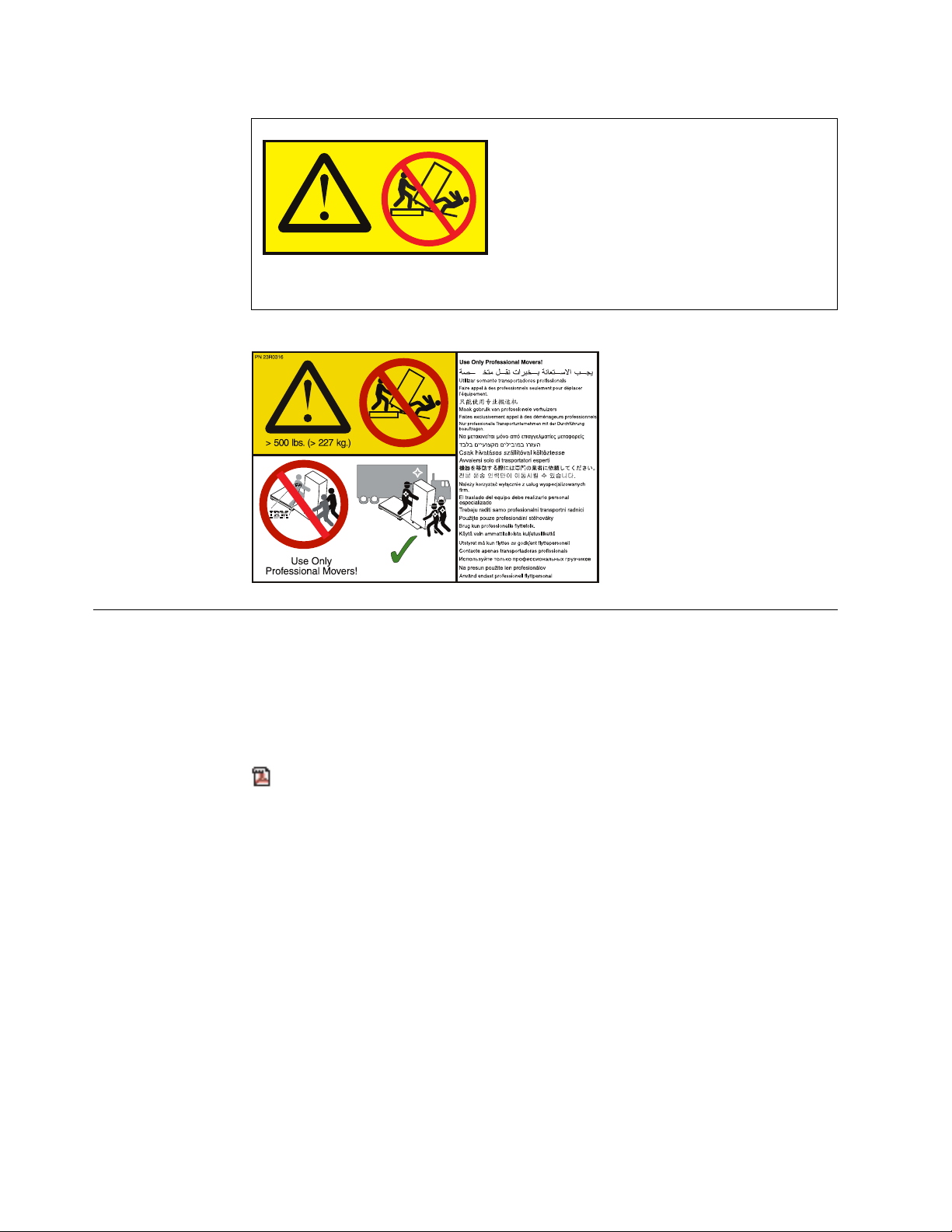
DANGER
xiv10012
Heavy equipment - personal injury or equipment damage might result if
mishandled. Use only professional movers.
Environmental notices
This publication contains all the required environmental notices for IBM Systems
products in 26 languages. The environmental notices that are included are
limitations, product recycling and disposal, product information, battery return
program, flat panel display, monitors and workstations, refrigeration, and
water-cooling system.
IBM Systems Environmental Notices and User Guide (ftp://
public.dhe.ibm.com/systems/support/warranty/envnotices/
environmental_notices_and_user_guide.pdf), Z125-5823
To view a PDF file, you need Adobe Reader. You can download it at no charge
from the Adobe website (get.adobe.com/reader/).
xvi IBM FlashSystem A9000R Models 9835-415 and 9837-415 Deployment Guide
Page 17

About this guide
This manual defines information regarding the deployment, configuration,
preinstallation requirements for IBM FlashSystem A9000R models 9835-415 and
9837-415. It is important to ensure that you meet all requirements to ensure a fast
and reliable deployment and installation.
If you cannot meet the deployment and installation requirements explained in this
document, notify your IBM representative to devise an alternative solution.
Who should use this guide
This publication is for personnel that are involved in planning. Such personnel
include IT facilities managers, individuals responsible for power, cooling, wiring,
network, and general site environmental planning and setup.
Roles and responsibilities
Both IBM and the customer have roles and responsibilities that they must adhere
to, in order to ensure proper workflow, timely successful installation, properly
configured Call Home and remote support, leading to a superior client experience.
Roles and responsibilities of the customer
v Review the product Deployment Guide
v Enable and work with the Remote Support Center (RSC) remote support in
performing remote data collection and support
v Work with the IBM Planning Representative (IPR), Service Representative (SSR),
Quality Practitioner (QPer), or other IBM personnel to fill out the Technical and
Delivery Assessment (TDA) for accurate and quicker initial installation
v Provide and prepare a rack, adhering to the rack requirements, as specified in
this guide.
v Provide adequate staffing/resources to support this solution.
v Provide sufficient bandwidth and host attachments to support this solution.
v Provide necessary Ethernet cabling
v Provide all initial host Fibre Channel (FC) and iSCSI cabling
v Provide proper power receptacles to match the requirements for the IBM
FlashSystem A9000R ordered
v Provide proper thermal dissipation, airflow and cooling, and environmental
requirements
v Provide proper floor space and clearance
v Provide access for the IBM service representative (SSR), including laptop or
computer access
v Provide access for movers and vehicles
v Allow firewall access to Call Home servers
v Setup IP host network
v Setup SAN host networking
v Download and install appropriate Host Attachment Kit (HAK)
© Copyright IBM Corp. 2016, 2017 xvii
Page 18

v Install the Management Server from Fix Central for IBM Hyper-Scale Manager
UI use
v Perform logical configuration
v Complete the host attachment plan
v Prepare Fibre Channel (FC) connections
v Prepare raised floor, if required
Roles and responsibilities of IBM Service Support
Representatives (SSRs)
v Complete Distant Learning (DL) education and hands-on education course
v Enroll in a hearing conservation program
v Perform product installation
v Configure Call Home and remote support
v Installation of software upgrades
v Installation of hardware Engineering Change Notices (ECA) also known as Field
Bill of Materials (FBM)
v Conduct product relocation, at customer request
v Perform break/fix repairs
v Return of failed parts that are under warranty or have a Certified Spare Parts
Value
v Keep customers informed of service activities
v Arrange time with customer/TA to facilitate upgrades
v Assist with break/fix support as requested by Remote Support Center, Top Gun,
or PFE team member
v Complete accurate Quality Service Activity Reporting (QSAR) reporting
Note: Additional information can be found in your the customer Enterprise Class
Support for Storage document, provided by the IBM Planning Representative (IPR).
Conventions used in this guide
These notices are used to highlight key information.
Tip: These notices provide important tips.
Note: These notices provide important guidance, or advice.
Important: These notices provide information or advice that might help you avoid
inconvenient or difficult situations.
Attention: These notices indicate possible damage to programs, devices, or data.
An attention notice is placed before the instruction or situation in which damage
can occur.
xviii IBM FlashSystem A9000R Models 9835-415 and 9837-415 Deployment Guide
Page 19
CAUTION:
These notices indicate a situation that is potentially hazardous to people
because of some existing condition or where a potentially dangerous situation
might develop because of some unsafe practice.
DANGER
These notices indicate a situation that is potentially lethal or hazardous to
people. For example, after a computer side panel is removed, exposed
high-voltage wires might be lethal.
Related information and publications
You can find additional information and publications related to IBM FlashSystem
A9000R on the following information sources.
v IBM FlashSystem A9000R on IBM Knowledge Center (ibm.com/support/
knowledgecenter/STJKN5) – on which you can find the following related
publications:
– IBM FlashSystem A9000R – Release Notes
– IBM FlashSystem A9000R – Product Overview
– IBM FlashSystem A9000R – Command-Line Interface (CLI) Reference Guide
– IBM FlashSystem A9000 and IBM FlashSystem A9000R – Application
Programming Interface (API) Reference Guide
– IBM Hyper-Scale Manager – Release Notes
– IBM Hyper-Scale Manager – User Guide
– IBM Hyper-Scale Manager – Representational State Transfer (REST) API
Specifications
– IBM XIV Remote Support Proxy – Release Notes
– IBM XIV Remote Support Proxy – Installation and User Guide
v IBM FlashSystem A9000 on IBM Knowledge Center (ibm.com/support/
knowledgecenter/STJKMM) – on which you can find the following related
publications:
– IBM FlashSystem A9000 – Release Notes
– IBM FlashSystem A9000 – Product Overview
– IBM FlashSystem A9000 – Deployment Guide
– IBM FlashSystem A9000 – Command-Line Interface (CLI) Reference Guide
– IBM FlashSystem A9000 and IBM FlashSystem A9000R – Application
Programming Interface (API) Reference Guide
– IBM XIV Remote Support Proxy – Release Notes
– IBM XIV Remote Support Proxy – Installation and User Guide
v IBM Flash Storage and Solutions marketing website (ibm.com/systems/storage/
flash)
v IBM Storage Redbooks®website (redbooks.ibm.com/portals/storage)
About this guide xix
Page 20
Getting information, help, and service
If you need help, service, technical assistance, or want more information about IBM
products, you can find various sources to assist you. You can view the following
websites to get information about IBM products and services and to find the latest
technical information and support.
v IBM website (ibm.com®)
v IBM Support Portal website (www.ibm.com/storage/support)
v IBM Directory of Worldwide Contacts website (www.ibm.com/planetwide)
IBM Publications Center
The IBM Publications Center is a worldwide central repository for IBM product
publications and marketing material.
The IBM Publications Center website (www.ibm.com/shop/publications/order/)
offers customized search functions to help you find the publications that you need.
You can view or download publications at no charge.
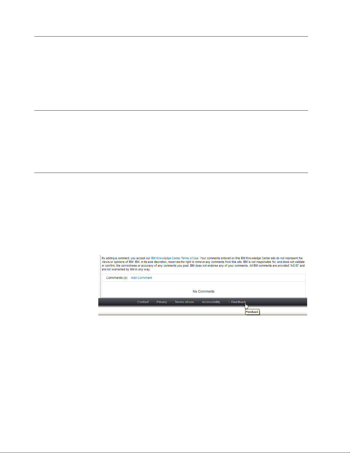
Sending or posting your comments
Your feedback is important in helping to provide the most accurate and highest
quality information.
Procedure
To submit any comments about this guide:
v Go to IBM FlashSystem A9000R on IBM Knowledge Center
(ibm.com/support/knowledgecenter/STJKN5), drill down to the relevant page,
and then click the Feedback link that is located at the bottom of the page.
The feedback form is displayed and you can use it to enter and submit your
comments privately.
v You can post a public comment on the Knowledge Center page that you are
viewing, by clicking Add Comment. For this option, you must first log in to
IBM Knowledge Center with your IBM ID.
v You can send your comments by email to starpubs@us.ibm.com. Be sure to
include the following information:
– Exact publication title and product version
– Publication form number (for example: GC01-0001-01)
– Page, table, or illustration numbers that you are commenting on
– A detailed description of any information that should be changed
xx IBM FlashSystem A9000R Models 9835-415 and 9837-415 Deployment Guide
Page 21

Note: When you send information to IBM, you grant IBM a nonexclusive right to
use or distribute the information in any way it believes appropriate without
incurring any obligation to you.
About this guide xxi
Page 22

xxii IBM FlashSystem A9000R Models 9835-415 and 9837-415 Deployment Guide
Page 23
Chapter 1. Overview
IBM FlashSystem A9000R is a grid-scale, all-flash storage platform designed to
drive your business into the cognitive era.
This guide defines deployment, planning, and preinstallation requirements for IBM
FlashSystem A9000R storage systems. It is important to ensure that you meet all
requirements to help achieve a fast and reliable installation.
FlashSystem A9000R provides consistent, extreme performance for dynamic data at
scale. The FlashSystem A9000R storage system integrates the microsecond latency
and high availability of IBM FlashCore®technology with grid architecture,
comprehensive data reduction, and industry leading IBM software.
Figure 1. IBM FlashSystem A9000R storage system
IBM FlashSystem A9000R is an excellent platform for industry leaders with rapidly
growing cloud storage and mixed workload environments. IBM software-defined
storage capabilities and IBM FlashCore technology combine to produce the extreme
performance and scalability required in enterprise-class storage solutions.
The storage system utilizes IBM MicroLatency®modules that leverage
IBM-enhanced MLC flash to provide density, low latency, high I/O, and high
availability. IBM FlashSystem A9000R aggregates grid elements (each containing
two grid controllers and one flash enclosure) within a 42U integrated rack solution.
(For more information about grid elements, see “FlashSystem A9000R grid
elements” on page 9).
Due the combination of grid-scale architecture and flash storage media, the system
delivers predictable high performance and ultra-low latency, even under heavy
workloads with full data reduction enabled. As a result, the grid-scale architecture
© Copyright IBM Corp. 2016, 2017 1
Page 24
maintains this performance by automatically self-optimizing workloads across all
storage resources without manual intervention. Secure multi-tenancy and quality of
service (QoS) features help ensure that tenant service levels are not compromised
within your complex environment.
Advanced management capabilities allow it to integrate easily into your existing
data center infrastructure and with a wide variety of hypervisor and virtualization
software, including VMware, OpenStack, and Microsoft.
For more information regarding the IBM FlashSystem A9000R grid scale
architecture, see Introduction > Architecture in the IBM FlashSystem A9000R Product
Overview (SC27-8559).
Planning best practices and requirements
Good planning is essential for the successful setup and use of your FlashSystem
A9000R. It ensures that you have everything you need and that you meet all the
prerequisites for the storage system. It minimizes errors and helps for a faster
installation process.
Use this planning information to place the FlashSystem A9000R system, plan
power and environmental needs, plan for software and storage needs, and prepare
for unique configurations that are based on how you plan to use the storage
system.
It is imperative that you work with the sales team, IBM Installation Planning
Representative (IPR), and IBM Service Representative (SSR) to capture information
needed to install and configure the storage system. This information is collected
during a Technical and Delivery Assessment (TDA) or Installation planning
meeting. This information must be collected prior to the commencement of the
installation, or delays may occur.
CAUTION:
You must prepare your environment to handle the FlashSystem A9000R
system based on this planning information with assistance from an IBM
installation planning representative (IPR) or an IBM service representative. The
final installation site within the computer room must be prepared before the
equipment is delivered. If the site cannot be prepared before the delivery time,
you must make arrangements to have the professional movers return to finish
the transportation later. Only professional movers can transport the equipment.
The IBM service representative can minimally reposition the rack at the
installation site, as needed to complete required service actions. You are also
responsible for using professional movers in the case of equipment relocation or
disposal.
If you cannot meet any of the installation requirements, notify your IBM service
representative to devise alternative solutions.
2 IBM FlashSystem A9000R Models 9835-415 and 9837-415 Deployment Guide
Page 25

Notes:
v This guide covers planning information for the IBM FlashSystem A9000R
integrated rack storage system.
For planning information for the IBM FlashSystem A9000 pod system, see IBM
FlashSystem A9000 Deployment Guide, GC27-8564 on the IBM FlashSystem A9000
Knowledge Center website (ibm.com/support/knowledgecenter/STJKMM).
v For information regarding management, automation, and access security, see the
following documentation, which can be found on the IBM FlashSystem A9000R
Knowledge Center website (ibm.com/support/knowledgecenter/STJKN5):
– IBM Hyper-Scale Manager User Guide, SC27-8560
– IBM Hyper-Scale Manager Release Notes
– IBM FlashSystem A9000R Command-Line Interface (CLI) Reference Guide,
SC27-8711
– IBM Hyper-Scale Manager REST API Specifications, SC27-6440
Chapter 1. Overview 3
Page 26

4 IBM FlashSystem A9000R Models 9835-415 and 9837-415 Deployment Guide
Page 27
Chapter 2. System specifications
This information compares general properties, performance, physical features, and
host connectivity for the IBM®FlashSystem™A9000R storage system.
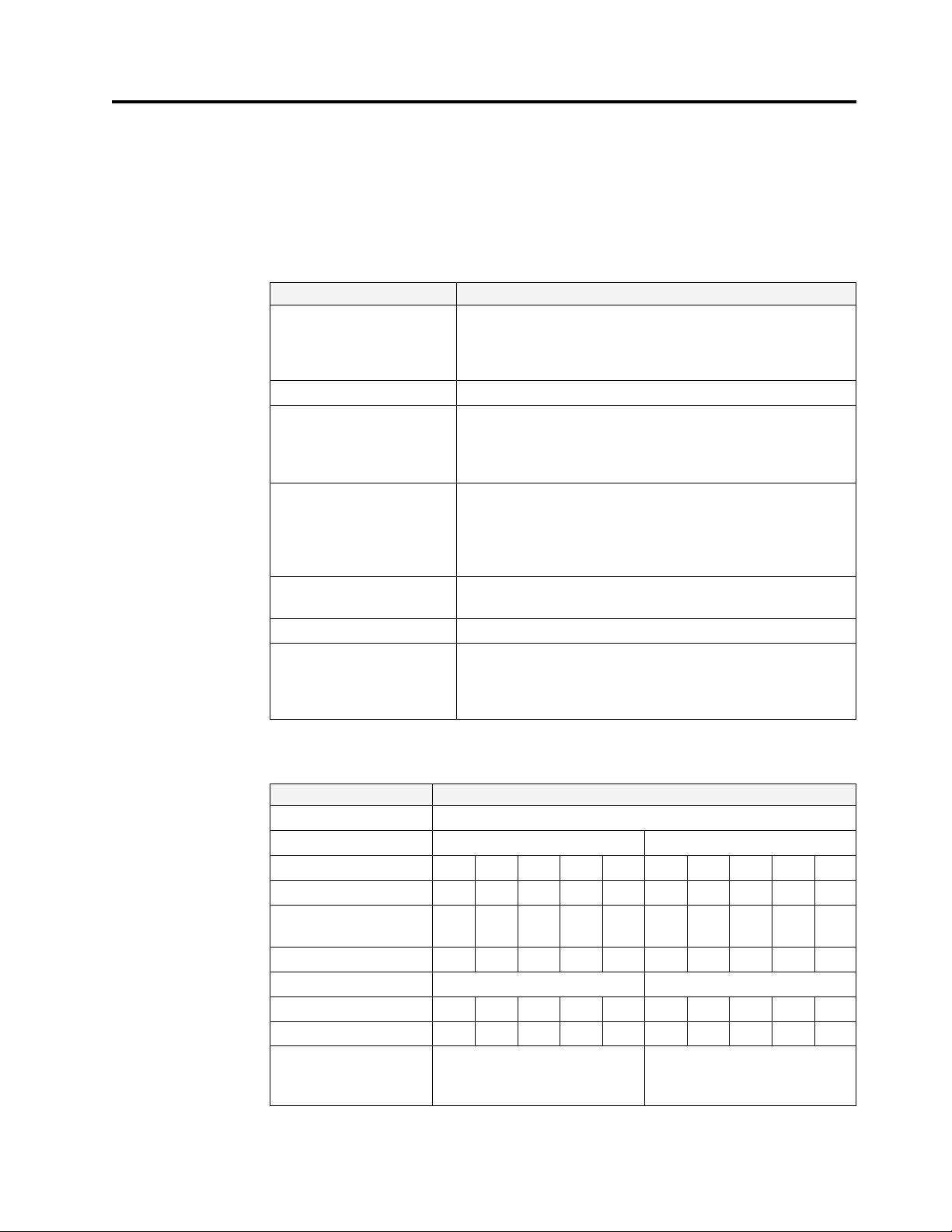
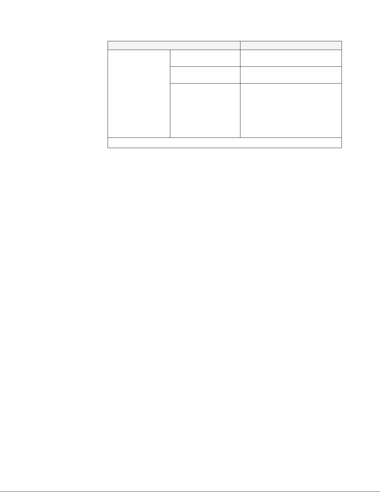
General properties
Specification Details
Controllers Up to 12 active grid controllers, each containing:
v Two Intel Xeon E5 v3 10-core 2.3 GHz processors
v 384 GB DDR4 memory
v Redundant battery backup units and power supply units
Software IBM FlashSystem A9000 and A9000R software v12.0
Models and warranties
Data reduction and
efficiency
Encryption Hardware-based AES-XTS 256-bit with centralized key
Backplane interconnect InfiniBand
Client operating system
support
v 9835-415: 1-year warranty
v 9837-415: 3-year enterprise-class warranty
Warranties include onsite service, same day 24×7
v Pattern removal
v Global, inline deduplication
v Inline compression
v Space-efficient snapshots
v Thin provisioning
management
For a current list of platforms supported, please visit the IBM
System Storage®Interoperation Center (SSIC)
(ibm.com/systems/support/storage/ssic/
interoperability.wss)
Storage capacity features
Specification Details
Flash type IBM-enhanced MLC
900 TB configuration 1.8 PB configuration
Flash enclosures 2 3 4 5 6 2 3 4 5 6
Effective capacity* (TB) 300 450 600 750 900 600 900 1200 1500 1800
Maximum capacity**
(TB)
Raw capacity (TB) 105.6 158.4 211.2 264.0 316.8 211.2 316.8 422.4 528 633.6
Flash enclosure type Flash enclosure-150 Flash enclosure-300
Flash enclosures 2 3 4 5 6 2 3 4 5 6
Grid controllers 4 6 8 10 12 4 6 8 10 12
IBM MicroLatency
modules per flash
enclosure
© Copyright IBM Corp. 2016, 2017 5
1400 2000 2600 3000 3000 1400 2000 2600 3000 3000
12 × 2.9 TB 12 × 5.7 TB
Page 28
Specification Details
*Typical effective capacity is the available capacity after system overhead (including
over-provisioning and RAID protection) and after the data reduction benefits of pattern
removal, deduplication and compression. this assumes data reduction of up to a multiple
of 5.26 to 1.
**Maximum capacity refers to the effective capacity provisioning limit.
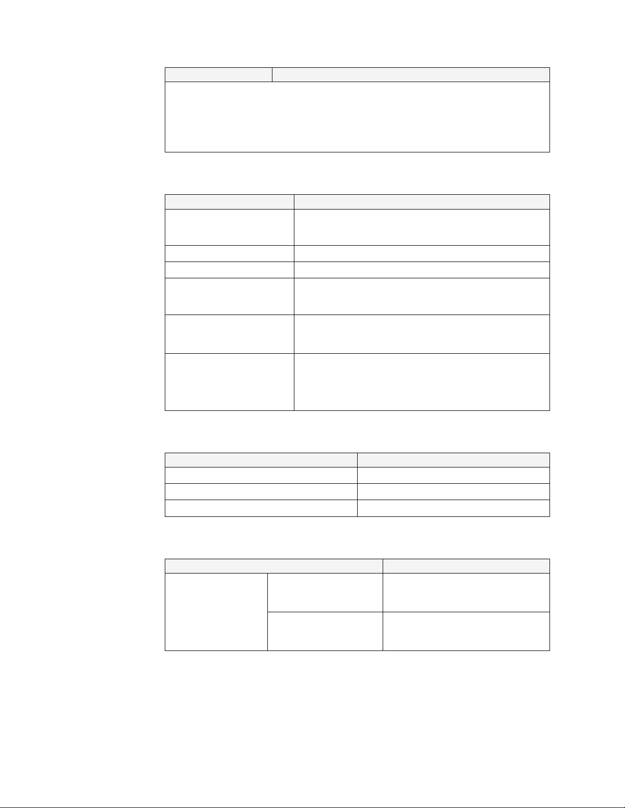
Physical features
Specification Details
Rack dimensions (H × W ×D)201.5 cm (42U) × 66.44 cm × 129.7 cm
(79.3 in. × 25.4 in. × 51.1 in.)
Front clearance 120 cm (47.2 in.)
Rear clearance 100 cm (39.4 in.)
Weight Entry configuration: 666 kg (1468 lb)
986 kg (2174 lbs)
Input voltage 200–240 V AC, 50/60Hz (+/-10% tolerance) via 30A–63A
Note: Dependent on input phase configuration type (single,
delta, or wye)
Power usage Entry configuration: 3.07 KW (typical); 4.82 KW (max)
Maximum configuration: 8.81 KW (typical); 13.91 KW (max)
See “Power consumption” on page 27.
Temperature
Specification Details
Temperature 10 - 35° C (50 - 95° F)
Maximum altitude 2134 m (7000 ft.)
Humidity 25 - 80% non-condensing
Host connectivity
Specification Details
Host system interfaces
(per grid controller)
Storage systems with
Fibre Channel (FC)
capabilities)
Storage systems with
iSCSI (Ethernet)
capabilities only
4 × 16 Gb Fibre Channel + 2 × 10 Gb
iSCSI
4×10 Gb iSCSI
6 IBM FlashSystem A9000R Models 9835-415 and 9837-415 Deployment Guide
Page 29
Specification Details
Host connectivity for
mirroring (per system)
Recommended minimum
link bandwidth value
Recommended maximum
50 Mbps
250 ms
round trip latency value
Attaching IBM
FlashSystem A9000 and
A9000R systems for
mirroring
The connection between two
FlashSystem A9000R systems, or
between a FlashSystem A9000R and a
FlashSystem A9000 system, has to
pass through:
v Ethernet LAN for iSCSI connections
v SAN for FC connections
Note: Synchronous remote mirroring is supported by version 12.0.1 and later.
Chapter 2. System specifications 7
Page 30

8 IBM FlashSystem A9000R Models 9835-415 and 9837-415 Deployment Guide
Page 31

Chapter 3. Physical configuration options
Use these general guideline for determining and ordering the feature codes that
you need to customize your IBM FlashSystem A9000R system.
Procedure
Note: Talk to your IBM planning representative (IPR) to help determine which
options are best for your needs.
To determine the required ordering information, answer the following questions:
1. Which model best fits your warranty requirements?
2. What are your capacity needs?
3. What are your performance requirements?
4. What type of host connectivity do you need?
5. What type of power input do you have?
6. Does the installation site meet the physical site requirements for the
FlashSystem A9000R and features that you plan to order? For example:
v Can you space the racks to allow for sufficient floor strength?
v Is there adequate cooling capacity to handle the new equipment?
v Is sufficient power available?
v Do you need 30A or 60A power cables?
v Is water cooling required?
7. Do you require any of the following:
v Any weight or height reduced shipping?
v A radio frequency identification device (RFID) tag?
What to do next
See the following information on the various physical configuration options for
your IBM FlashSystem A9000R storage system.
v “FlashSystem A9000R grid elements”
v “Components and interconnect” on page 10
v “Rack configurations” on page 11
v “Flash enclosure components and feature codes” on page 13
v “Grid controller components and feature codes” on page 14
v “Rear-door heat exchanger” on page 15
v “Weight-reduced shipping option” on page 17
v “Height reduced shipping option” on page 17
v “Radio frequency identification device option” on page 18
FlashSystem A9000R grid elements
A grid element is an orderable bundle that ensures only valid FlashSystem A9000R
rack configurations.
Each grid element contains two grid controllers and one flash enclosure, as shown
in Figure 2 on page 10.
© Copyright IBM Corp. 2016, 2017 9
Page 32

fsa9k145
Figure 2. Grid element – 2 grid controllers and 1 flash enclosure
Grid elements can be ordered according to your performing and capacity needs.
Configurations range between a minimum of two grid elements to a maximum of
six grid elements. Partially populated configurations contain three, four, or five
grid elements.
For more information on rack configurations, see “Rack configurations” on page
11.
All configurations have the same power, floor planning, hardware, and software
configurations as fully populated systems.
Important: Each grid controller in a system rack is equally connected to each flash
enclosure in the system, regardless of how many elements are in the system.
Components and interconnect
This section lists the components and interconnection options that are supplied
with each IBM FlashSystem A9000R integrated rack.
Table 1 breaks down the various components and sub-components of the IBM
FlashSystem A9000R.
Table 1. Components and interconnection options in IBM FlashSystem A9000R
Component Sub-components
IBM T42 rack
4 - 12 grid controllers, depending on
ordered configuration
2 - 6 flash enclosures, depending on
ordered configuration
Two InfiniBand switches
Each grid controller includes:
v Two hot-swappable power supply units (PSUs)
v Two internal battery modules
v Two data reduction hardware acceleration cards
v Two or three dual-ported host adapters,
configuration according to customer request
– Two 16 Gb Fibre Channel dual ports (total
four ports) and a 10 Gb Ethernet (iSCSI) dual
port (total two ports) adapter or
– Two 10 Gb Ethernet (iSCSI) dual port (total
four ports) adapters
v 12 hot-swap 2.9 or 5.7 TB IBM MicroLatency
modules
v Two internal battery modules
10 IBM FlashSystem A9000R Models 9835-415 and 9837-415 Deployment Guide
Page 33

Table 1. Components and interconnection options in IBM FlashSystem A9000R (continued)
Component Sub-components
Two power distribution units (PDUs)
Utility patch panel
Others
Rack configurations
IBM FlashSystem A9000R supports racks that contain a total of two to six grid
elements.
For various configuration feature codes see:
v “Flash enclosure components and feature codes” on page 13
v “Grid controller components and feature codes” on page 14
v “Main power cables specifications” on page 29
Note: An IBM FlashSystem A9000R with less grid controllers also has fewer usable
Fibre Channel and iSCSI ports, as well as less processing power.
v Three management ports
v Two VPN ports
v Maintenance module
v External modem
v Internal cabling
For more information regarding capacity, processors, memory, and connectivity, see
Chapter 2, “System specifications,” on page 5.
Fully populated rack
A fully populated rack contains 12 grid controllers and 6 flash enclosures.
Note: A valid configuration always has two times the amount of grid controllers
than flash enclosures.
Each grid controller contains 384 GB RAM capacity, for a total of 4608 GB RAM for
a fully populated rack.
Each flash enclosure supports RAID 5 (10+1 MicroLatency modules with
distributed parity, in accordance to RAID 5) with one spare MicroLatency module
(total 12 MicroLatency modules). The physical capacity is equal to 10 MicroLatency
modules with 2.9 TB or 5.7 TB, giving a total of either 29 TB or 57 TB per flash
enclosure and 174 TB or 342 TB for a fully populated rack.
Figure 3 on page 12 shows an example the front and back of a fully populated IBM
FlashSystem A9000R.
Chapter 3. Physical configuration options 11
Page 34

Figure 3. Fully-populated IBM FlashSystem A9000R
Minimally populated rack
A minimally populated rack contains four grid controllers and two flash
enclosures.
Each grid controller contains 384 GB RAM, for a total of 1536 GB RAM for a
minimally populated rack.
Each flash enclosure supports RAID 5 (10+1 MicroLatency modules with
distributed parity, in accordance to RAID 5) with one spare MicroLatency module
(total 12 MicroLatency modules). The physical capacity is equal to 10 MicroLatency
12 IBM FlashSystem A9000R Models 9835-415 and 9837-415 Deployment Guide
Page 35

modules with 2.9 TB or 5.7 TB, giving a total of either 29 TB or 57 TB per flash
enclosure and 58 TB or 114 TB for a minimally populated rack.
Figure 4 shows an example of the front and back of a minimally populated IBM
FlashSystem A9000R.
Figure 4. Minimally-populated IBM FlashSystem A9000R
Flash enclosure components and feature codes
Each flash enclosure contains 12 hot-swap 2.9 TB or 5.7 TB IBM MicroLatency
modules. The flash enclosures are used for IBM FlashSystem A9000R storage
functions.
Chapter 3. Physical configuration options 13
Page 36

Each rack unit contains 2 - 6 flash enclosures, according to customer specifications.
Figure 5 and Figure 6 illustrate the front and rear of the flash enclosure.
▌1▐ Battery modules
▌2▐ LED indicator panel
▌3▐ IBM MicroLatency modules
Figure 5. Front of a flash enclosure
▌1▐InfiniBand Adapters (two per canister)
▌2▐Internal interconnect Infiniband ports
▌3▐Canister 1
▌4▐Canister 2
▌5▐Maintenance ports (serial) (IBM technician access)
▌6▐Management ports (Ethernet) (IBM technician access)
Figure 6. Rear of a flash enclosure
Table 2. Feature codes for flash enclosures
Description Feature code
Flash enclosure with 12 x 2.9 TB IBM MicroLatency modules AFE2
Flash enclosure with 12 x 5.7 TB IBM MicroLatency modules AFE3
Grid controller components and feature codes
Each grid controller contains two hard disk drives (HDDs) and two solid state
drives (SSDs) for IBM FlashSystem A9000R performance functions.
Each rack unit contains 4 - 12 grid controllers, according to customer specifications.
Figure 7 on page 15 illustrates the front of the grid controller. Figure 8 on page 15
and Figure 9 on page 15 illustrate the two rear options for the grid controller.
14 IBM FlashSystem A9000R Models 9835-415 and 9837-415 Deployment Guide
Page 37

fsa9k058
4
5
2
1
3
▌1▐HDDs (two per grid controller)
▌2▐SSDs (two per grid controller)
▌3▐Battery modules (two per grid controller)
▌4▐Battery module Fault LED (one per unit)
▌5▐General battery module LEDs
Figure 7. Front of a grid controller
Figure 8. Rear of a grid controller with FC configuration
Figure 9. Rear of a grid controller with 10 Gb Ethernet configuration
Table 3. Feature codes for grid controllers
Description Feature code
Grid controller with four 16 Gb Fibre Channel (FC) + two 10 GbE
iSCSI ports
Grid controller with four 10 GbE iSCSI ports 5002
Rear-door heat exchanger
The rear-door heat exchanger (feature code AFR1) is an optional water-cooled
device that is mounted on the rear of an IBM FlashSystem A9000R system. It cools
the air that is heated and exhausted by devices inside the rack.
A supply hose delivers chilled, conditioned water to the heat exchanger. A return
hose delivers warmed water back to the water pump or chiller (referred to as the
secondary cooling loop).
5001
Chapter 3. Physical configuration options 15
Page 38

The primary cooling loop supplies the building chilled water to secondary cooling
loops and air conditioning units.
Note: The hoses for the secondary cooling loop are not included with this option.
The rack on which you install the heat exchanger can be on a raised floor or a
non-raised floor.
The rear-door heat exchanger option consists of the following components that are
shown in Figure 10.
v Door assembly
v Hinge kit
v Air-purge tool
▌1▐Door assembly
▌2▐Hinge kit
▌3▐Air-purging tool
Figure 10. Rear-door heat exchanger option kit
The following table lists the rear-door heat exchanger feature code for the
FlashSystem A9000R system.
16 IBM FlashSystem A9000R Models 9835-415 and 9837-415 Deployment Guide
Page 39

Table 4. Rear-door heat exchanger features
Feature description Feature code
Rear-door heat exchanger AFR1
See “Preparing for the rear-door heat exchanger” on page 26 for information about
the requirements for preparing the installation site before the rear-door heat
exchanger feature can be installed.
Weight-reduced shipping option
This information describes the Weight Reduction shipping option for the storage
system, feature code AFR3.
IBM offers weight reduced shipping for all IBM FlashSystem A9000R system
configurations. This optional feature provides that the weight of the rack is only
approximately 440 kg (970 lb) for traversal at the delivery site.
This option is ordered for installations where receiving an assembled storage unit,
or ordering feature code AFR2 would be impractical, due to greater weight
limitations.
The unit is delivered fully tested but partially disassembled into several easily
transported subassemblies. This feature allows racks to be safely transported on
lower weight capacity elevators.
At the installation site the system is unpacked by IBM technicians, and the front
door, rear door and side covers are temporarily removed so that the rack assembly
can then be carried up stairs, hoisted via crane through windows, tipped to fit
through low doorways, and rolled through low doorways in the customer's facility.
At the final destination, all devices that were shipped separately can be installed.
A fully configured FlashSystem A9000R system, including packaging, weighs
approximately 986 kg (2174 lbs).
Attention: The storage system must not be tilted more than 10 degrees.
Note: This option greatly increases the system installation time. Onsite
coordination is needed for both the IBM service representative and the professional
movers.
Height reduced shipping option
This information describes the Height Reduction shipping option for IBM
FlashSystem A9000R, feature code AFR2.
If your site does not meet the delivery clearances that are shown in “Rack
dimensions and service clearance requirements” on page 22, the height reduced
shipping option can be ordered to reduce the height of the rack by 30 cm (11.8 in.)
Chapter 3. Physical configuration options 17
Page 40

After the rack is delivered, the IBM service representative removes the rack top
cover so that the rack can be moved to the final location. Only professional movers
can transport the equipment.
After the rack is in its final location, the IBM service representative must return to
complete the installation, including reinstalling the rack top cover.
A fully configured FlashSystem A9000R system, including packaging, weighs
approximately 986 kg (2174 lbs) with dimensions of 66 cm × 118 cm
(26 in. × 46.5 in.).
Attention: The storage system must not be tilted more than 10 degrees.
Note: This option greatly increases the system installation time. Onsite
coordination is needed for both the IBM service representative and the professional
movers.
Radio frequency identification device option
IBM offers an optional radio frequency identification device (RFID) for the storage
system, feature code AFR5.
If you use frequency identification device (RFID) technology to track equipment in
your data centers, you can order the RFID option to attach an RFID tag to system
racks.
This RFID is designed to meet the performance and numbering specification as
outlined by the radio frequency identification specifications. For information about
the specification, see the Financial Services Technology Consortium website
(www.bits.org/?id=29).
Important: This option is applicable only in environments that can use the correct
RFID reading technology. Before you order this option, review the RFID
capabilities with your IBM service representative.
When this option is ordered, IBM attaches one RFID tag per rack. Order one RFID
option for each FlashSystem A9000R that you want to track. This option does not
tag individual components.
This option can be ordered only when a new rack is ordered. The RFID option
cannot be ordered as a miscellaneous equipment specification (MES).
Important: If the tag must be replaced for an IBM FlashSystem A9000R system,
ensure that you update the asset-management database with the new RFID
number for that FlashSystem A9000R.
18 IBM FlashSystem A9000R Models 9835-415 and 9837-415 Deployment Guide
Page 41

Chapter 4. Physical installation site requirements
The location where you plan to install the storage system must meet all
requirements.
Plan your installation site with assistance from an IBM installation planning
representative (IPR) or an IBM service representative.
Prepare the site in advance so that professional movers or riggers can transport the
equipment to the final site within the computer room. If the site cannot be
prepared before the delivery time, you must make arrangements to have the
professional movers return to finish the transportation later.
Attention: Only professional movers can transport the equipment.
An IBM service representative installs the storage system. The IBM service
representative can only minimally reposition the rack within the room, as needed
to complete required service actions.
Professional movers or riggers are required to transport the FlashSystem A9000R
rack as close to the installation site as possible because of its weight.
Note: Professional movers or riggers are also required to relocate or dispose of the
FlashSystem A9000R system.
The physical installation site requirements are listed in the following sections:
v “Floor and space requirements”
v “Power requirements” on page 26
v “Environmental requirements” on page 32
v “Planning for the rear-door heat exchanger” on page 38
v “Site security considerations” on page 60
Floor and space requirements
Ensure that the location of the FlashSystem A9000R system meets floor and space
requirements.
Procedure
Complete the following steps to ensure that the planned installation location meets
space and floor load requirements:
1. Decide whether the FlashSystem A9000R system is to be installed on a raised
floor. See “Raised or non-raised floor considerations” on page 20.
2. Determine whether the floor meets the floor-load requirements for the
FlashSystem A9000R system. See “Floor-load requirements” on page 21.
3. Calculate the amount of space needed for the rack footprint and service
clearance requirements. See “Rack dimensions and service clearance
requirements” on page 22.
© Copyright IBM Corp. 2016, 2017 19
Page 42

4. Determine where to place the rack in the installation site, based on the
floor-load and space requirements.
5. If the location has a raised floor, prepare the raised floor with cable cutouts and
required ventilation. See “Preparing for raised-floor installation and cabling” on
page 24.
6. If the location is not a raised floor, resolve any safety concerns that are caused
by the location of overhead-cable exits and cable routing. See “Preparing for
non-raised-floor installation and cabling” on page 25.
7. Provide your IBM service representative with the following information before
the installation:
a. Whether under-floor or over-head power-cabling scheme is to be used.
b. The distance of the rack from the power receptacles.
8. If a rear-door heat exchanger is being ordered, be sure to follow instructions in
“Preparing for the rear-door heat exchanger” on page 26.
9. If absorbent padding is used where the rack casters (wheels) are located, be
sure to follow instructions in “Bottom rack dimensions” on page 23.
Raised or non-raised floor considerations
The IBM FlashSystem A9000R storage system can be installed on a raised or a
non-raised floor.
Raised floor considerations
Installing the racks on a raised floor provides the following benefits:
v Improves operational efficiency and provides greater flexibility in the
arrangement of equipment.
v Increases air circulation for better cooling.
v Protects the interconnecting cables and power receptacles.
v Prevents tripping hazards because cables can be routed underneath the raised
floor.
When you install on a raised floor, consider the following factors:
v The raised floor must be constructed of fire-resistant or noncombustible material.
v Avoid the exposure of metal or highly conductive material at ground potential
to the walking surface when a metallic raised floor structure is used. Such
exposure is considered an electrical safety hazard.
v The raised floor height must be at least 30.5 cm (12 in.). Clearance must be
adequate to accommodate interconnecting cables, Fibre Channel (FC) cable
raceways, power distribution, and any piping that is present under the floor.
Floors with greater raised floor heights allow for better equipment cooling.
v When a raised floor tile is cut for cable entry or air supply, an extra floor tile
support (pedestal) might be required to restore the structural integrity of the
panel to the previous requirement.
v The use of a protective covering (such as plywood, tempered masonite, or
plyron) is required to prevent damage to floor tiles, carpeting, and panels while
equipment is being moved into or is relocated within the installation site. When
the equipment is moved, the dynamic load on the casters is greater than when
the equipment is stationary.
v Concrete subfloors require treatment to prevent the release of dust.
20 IBM FlashSystem A9000R Models 9835-415 and 9837-415 Deployment Guide
Page 43

v Use noncombustible protective molding to eliminate sharp edges on all floor
cutouts to prevent damage to cables and hoses, and to prevent casters from
rolling into the floor cutout.
v Seal raised-floor cable openings to prevent the escape of chilled air.
v Pedestals must be firmly attached to the structural (concrete) floor by using an
adhesive.
For more information, see “Preparing for raised-floor installation and cabling” on
page 24.
Non-raised floor considerations
Raised floors are preferred because they provide better support for the cabling and
to ensure efficient cooling for the FlashSystem A9000R system; however, overhead
cabling at the rear of the rack is available when the FlashSystem A9000R system is
installed on a non-raised floor.
Unlike raised-floor cabling, the installation planning, cable length, and the rack
location, in relation to the cable opening at the top of the rack, are critical to the
successful installation when using overhead cabling.
For more information, see “Preparing for non-raised-floor installation and cabling”
on page 25.
Floor-load requirements
You must ensure that the floor load rating can support the weight of the
FlashSystem A9000R system.
Floor reinforcement must support the weight of the FlashSystem A9000R system
over a specific area, as shown in Table 5. These measurements are slightly less than
the footprint area of the system, due to the overhang of the door.
To support future scale-out capability (MES) upgrades, the installation site must
provide floor weight-support requirements to support a full rack configuration.
Table 5. Floor weight-support requirements
Grid element configuration Floor reinforcement area Total weight
12 grid controllers and 6 flash
enclosures
10 grid controllers and 5 flash
enclosures
8 grid controllers and 4 flash
enclosures
6 grid controllers and 3 flash
enclosures
4 grid controllers and 2 flash
enclosures
66 cm × 118 cm (26 in. × 46.5 in.) 986 kg (2174 lbs)
66 cm × 118 cm (26 in. × 46.5 in.) 906 kg (1998 lbs)
66 cm × 118 cm (26 in. × 46.5 in.) 826 kg (1821 lbs)
66 cm × 118 cm (26 in. × 46.5 in.) 746 kg (1645 lbs)
66 cm × 118 cm (26 in. × 46.5 in.) 666 kg (1468 lbs)
Note: The same floor-loading requirements apply to partially populated and fully
populated racks.
Chapter 4. Physical installation site requirements 21
Page 44

The rear-door heat exchanger adds more weight to the rack. For information about
the weight of an empty and filled door, see “Rear-door heat exchanger” on page
15.
To ensure that all requirements are met, obtain the service of a qualified structural
engineer to prepare the floor.
Important: If you do not know or are not certain about the floor-load rating of the
installation site, you must check with the building engineer or another appropriate
person.
Rack dimensions and service clearance requirements
The installation site must accommodate the rack dimensions and minimum service
clearance for the FlashSystem A9000R system.
The IBM service representative must have enough space to open the front and rear
covers to service the FlashSystem A9000R system, including removing components
and other assemblies from the FlashSystem A9000R system.
Notes:
v You can position racks no closer than 45 cm (17.7 in.) to a wall.
v You can position racks alongside (next to) other racks.
v Because several rack designs are available from IBM and other vendors, space
between adjacent racks might be required to open the door for service. You must
determine the space requirement at the time of installation.
Table 6 and Figure 11 on page 23 describe dimensions and minimum service
clearance for the FlashSystem A9000R system.
Table 6. Rack dimensions and clearance requirements
Dimension Clearance
Height 201.5 cm (79.3 in.)
Depth 129.7 cm (51.1 in.)
Width 64.4 cm (25.4 in.)
Front clearance 120 cm (47.2 in.)
Rear clearance 100 cm (39.4 in.)
Side (door) clearance 10 cm (3.9 in.)
22 IBM FlashSystem A9000R Models 9835-415 and 9837-415 Deployment Guide
Page 45

Figure 11. Clearance requirements for servicing the FlashSystem A9000R rack
Bottom rack dimensions
When using absorbent padding where the rack casters (wheels) are located, use
this information for proper pad placement.
Figure 12 on page 24 shows the bottom rack dimensions and castor placements.
Chapter 4. Physical installation site requirements 23
Page 46

Figure 12. Bottom rack dimensions and castor placements
Preparing for raised-floor installation and cabling
Prepare the raised floor with cable cutouts, required ventilation, and additional
floor support, if necessary.
Procedure
Complete the following steps to prepare for cabling each FlashSystem A9000R
based on raised floor with 60 × 60 cm (24 × 24 in.) tiles:
1. Based on your planned layout, ensure that the installation site can
accommodate the locations of the cables exiting each FlashSystem A9000R rack.
2. Plan for the FlashSystem A9000R system to be positioned on two tiles, with the
rear of the rack aligned on a floor-tile seam and with two full rows of
24 IBM FlashSystem A9000R Models 9835-415 and 9837-415 Deployment Guide
Page 47

perforated tiles immediately in front of the rack (see Figure 13).
Figure 13. Raised floor requirements
3. Cut a 200 × 200 mm (8 × 8 in.) opening in the rear floor tile for under-floor
cabling and electricity (see Figure 13).
Notes:
v Place the opening under the FlashSystem A9000R system, centered on the back
edge of the tile along the rear of the rack.
v Sizing the cutout correctly is important. An oversized cutout permits excessive
cooling loss and weakens the floor tile. An undersized cutout must be enlarged,
which causes an installation delay while the tile is replaced or the cutout is
enlarged.
4. To allow for ventilation for airflow and support system cooling requirements,
have at least two tiles (and preferably more) in front of the FlashSystem
A9000R system (see Figure 13). These tiles must have a minimum of 40%
perforation.
5. If the rear-door heat exchanger is ordered, see “Raised floor hose requirements
and management” on page 51 for additional floor preparation steps.
Preparing for non-raised-floor installation and cabling
Prepare the installation site to accommodate overhead cabling for mainline-power
cables, customer Fibre Channel (FC) and Ethernet host cables as well as network
Ethernet cables.
Using overhead cabling provides many of the cooling and safety benefits that are
provided by raised flooring in a non-raised floor environment.
Unlike raised-floor cabling, the installation planning, cable length, and the system
location in relation to the cable entry point are critical to the successful installation
of a top cable exit.
Chapter 4. Physical installation site requirements 25
Page 48

Notes:
v Main power cables are routed to the rack by the customer, and internally routed
and connected by an IBM service representative.
v Host-attachment cables are internally routed and connected by either the
customer or by an IBM service representative.
v All remaining cables are internally routed and connected by an IBM service
representative.
If the rear-door heat exchanger is ordered, see “Non-raised floor hose requirements
and management” on page 55 for more floor preparation steps.
Installation and safety requirements
If the cables are too long, there might not be enough room inside of the rack to
handle the extra length and the extra cable might interfere with the servicing tasks,
preventing concurrent repair.
IBM Corporate Safety restricts the servicing of your overhead equipment to a
maximum of 10 feet from the floor. Therefore, your power source must not exceed
10 feet from the floor and must be within 5 feet of the top of the rack.
Servicing any overhead equipment higher than 10 feet requires a special bid
contract. Contact your IBM Representative for more information about special bids.
Preparing for the rear-door heat exchanger
An optional rear-door heat exchanger (feature code AFR1) may be ordered to help
cool your system.
To complete the rear-door heat exchanger site preparation, follow the instructions
in “Planning for the rear-door heat exchanger” on page 38.
Power requirements
Ensure that your operating environment meets the AC-power and voltage
requirements.
The FlashSystem A9000R system is designed with backup battery modules in order
to maintain power to the storage system in the event of an AC-power loss.
The FlashSystem A9000R system has redundant main power cables. For
two-main-power-cable configuration, you must supply power from two
independent sources of electricity.
Consult with an IBM service representative to discuss power source options for the
four-main-power-cable configuration.
Note: Removing all AC power from the FlashSystem A9000R system causes an
emergency shutdown. All modified data is then saved to drives, and the system
turns off within 5 minutes.
26 IBM FlashSystem A9000R Models 9835-415 and 9837-415 Deployment Guide
Page 49

Customer responsibilities
v You must supply enough branch circuits to prevent overloading from the
equipment that you install.
v You must ensure that each electrical outlet is correctly wired and grounded to
prevent an electrical shock.
IBM responsibilities
v The IBM service representative completes several checks, including voltage and
grounding checks before the power to the FlashSystem A9000R system is
connected.
v The IBM service representative connects power to the racks and initially powers
on the equipment.
Power outlet requirements
Ensure that the installation site has the required power outlets.
Two independent power outlets are required for the two main power cords that
are needed by each FlashSystem A9000R system.
Important: To eliminate a single point of failure, the outlets must be independent.
This means that each outlet must use a separate power source and each power
source must have its own wall circuit breaker.
For the most reliable operation, do not use Ground Fault Circuit Interrupter
(GFCI), Earth Leakage Circuit Breaker (ELCB), and Residual Current Circuit
Breaker (RCCB) type circuit breakers with the FlashSystem A9000R system.
The FlashSystem A9000R system is certified for safe operation and is compliant
with IEC, EN, UL, CSA 60950-1 standards. However, if leakage detection circuit
breakers are required by local electrical practice, the breakers must be sized for a
leakage-current rating of 100 mA or greater to reduce the risk of server outage
caused by erroneous and spurious tripping.
Power sources
Several AC power source configurations are available.
v Four 60/63 A, 200-240 V AC, North American, EMEA, and Japan single-phase
receptacles, each connected to a different power source.
v Two 60 A, 200-240 V AC, US and Japan delta three-phase receptacles, each
connected to a different power source.
v Two 30/32 A, 200-240 V AC (Line-to-Neutral [LN]), EMEA WYE three-phase
receptacles, each connected to a different power source
The storage system is protected from a power outage by internal backup battery
modules. However, you can reduce the risk of a power outage by connecting the
system to an external uninterruptible power supply, a backup generator, or both.
Power consumption
This information describes the power consumption for partial and full rack
configurations.
Table 7 on page 28 lists the power consumption for each rack configuration.
Chapter 4. Physical installation site requirements 27
Page 50

The power consumption for partial-rack configurations is the typical value and is
provided only for reference purposes.
To support concurrent capacity upgrades (scale-out procedures), the installation
site must provide sufficient power capacity to support performance on the new
rack configuration.
Note: It is highly recommended that the installation site supports the requirements
for a full rack system, in order to support any future capacity upgrade procedures.
The measurements in the Table 7 was taken in an environment with a room
temperature of 18°C (64.4°F), all fans at nominal/idle speed, and battery modules
were not charging.
Table 7. Power consumption
2.9 TB MicroLatency
modules
Idle / light load power
Configuration
4 grid controllers and 2 flash
enclosures
6 grid controllers and 3 flash
enclosures
8 grid controllers and 4 flash
enclosures
10 grid controllers and 5
flash enclosures
12 grid controllers and 6
flash enclosures
1
The numbers for power consumption of 2.9 TB MicroLatency modules are estimates.
consumption in kVA
3.420 3.820
5.034 5.634
6.448 7.448
8.262 9.262
9.876 11.076
1
5.7 TB MicroLatency
modules
Idle / light load power
consumption in kVA
Input voltages and frequencies
This information lists the voltages or frequencies that are accepted by the
FlashSystem A9000R system.
Table 8 provides the voltages and frequencies that are accepted by the FlashSystem
A9000R system. For more information, see “Leakage current” on page xiv.
Table 8. Input voltages and frequencies
3 Ø n (3-phase
Delta) (3W +PE)
Characteristics
Nominal input
operating rated range
voltages
Maximum branch
circuit protection
rating
Minimum tolerant
input voltage
28 IBM FlashSystem A9000R Models 9835-415 and 9837-415 Deployment Guide
voltage or frequency
200 - 240 V AC LL: 346 - 415 V AC
60/63 A 30/32 A 60/63 A
180 V AC LL: 312 V AC
3 Ø Y (3-phase Wye)
(3W + N+ PE)
voltage or frequency
LN: 200 - 240 V AC
LN: 180 V AC
1 Ø (Single-phase,
Line-to-Neutral (LN)
or Line-to-Line (LL))
200 - 240 V AC
180 V AC
Page 51

Table 8. Input voltages and frequencies (continued)
3 Ø n (3-phase
Delta) (3W +PE)
Characteristics
Maximum tolerant
input voltage
Maximum
ground-leakage
current
Steady-state input
frequencies
Power®line
disturbance (PLD)
input frequencies
voltage or frequency
264 V AC LL: 457 V AC
3.84 mA 3.45 mA 11.6 mA
50±3 Hz or 60±3 Hz 50±3 Hz or 60±3 Hz 50±3 Hz or 60±3 Hz
50±3 Hz or 60±3 Hz 50±3 Hz or 60±3 Hz 50±3 Hz or 60±3 Hz
Main power cables specifications
Plan for power cable, connector, and receptacle requirements.
The FlashSystem A9000R system is available in multiple main power cable
configurations.
Attention: The regional designations are general. If the input voltage for the
country uses a wye circuit, use the appropriate main power cables for EMEA
(Europe, Middle East, and Africa) and Asia/Pacific.
3 Ø Y (3-phase Wye)
(3W + N+ PE)
voltage or frequency
LN: 264 V AC
1 Ø (Single-phase,
Line-to-Neutral (LN)
or Line-to-Line (LL))
264 V AC
If input voltage for the country uses a delta circuit, use the appropriate main
power cables for United States, Canada, Latin America.
For more information about electric currents for various countries, see the
International Trade Administration website (http://trade.gov/publications/
abstracts/electric-current-abroad-2002.asp).
Main power cable feature codes
The following table provides the feature codes and description details for each
main power cable.
Note: The main power cables are provided with the connector feature codes listed
in the following table. Receptacle feature codes in the following table are
recommended.
Although equivalent receptacles can be used, it is the responsibility of the
customer to verify compatibility.
Chapter 4. Physical installation site requirements 29
Page 52

Table 9. Main power cables
Mainpower
cable
feature
code
1050 60A-
Wall
connector Description
Main-power cable for United
250VACIEC3092P3W-IP67
States, Canada, Latin America, and
Japan; single-phase, 60 A
plug-class (or 60 A rated class
plug), two conductors+ground
with plug
Line cord
connector
Hubbell
HBL360P6V04
Customer
facility
Hubbell
HBL360R6W
Inline
receptacle
Hubbell
HBL360C6W
System (PDU)
connector
70A500VAC(RMS)3pos
1051 N/A Main-power cable for United
States, Canada, Latin America, and
Japan; single-phase, 60/63 A rated
branch-circuit class, two
conductors+ground, hardwired
1052 60A-
250VACIEC3093P4W-IP67
Main power cable for United
States, Canada, Latin America, and
Japan; three-phase delta, 60 A
rated plug-class, three
wires+ground with plug
Hardwired
or uses
clientprovided
connector
Hubbell
HBL460P9V05
Hardwired
AC supply
Hubbell
HBL460R9W
N/A 70A-
500VAC(RMS)3pos
Hubbell
HBL460C9W
70A500VAC(RMS)4pos
30 IBM FlashSystem A9000R Models 9835-415 and 9837-415 Deployment Guide
Page 53

Table 9. Main power cables (continued)
Mainpower
cable
feature
code
1053 N/A Main power cable for Europe,
Wall
connector Description
Middle East, Asia/Pacific (except
Japan), Australia, and New
Zealand; three-phase wye,
30/32 A rated branch-circuit class,
three wires+neutral + ground,
hardwired
Main power cable considerations
The following information provides details to consider regarding main power
cables for IBM FlashSystem A9000R systems:
v Main power cables are up to 250 V 60/63 A or 250 V 30/32 A rated maximum
branch circuit classes.
Single-phase main power cables have two conductors (where the second
conductor may be referred to as L2 or N, depending on the installation region
mains type implementation) and three wires.
Three-phase main power cables have three poles and four wires, or four poles
and five wires.
Plugs and receptacles for feature codes 1050 and 1052 are IEC309-compliant.
v Bulk wire conductor sizes for main power cable feature codes are:
– 1050, 1051, and 1052: 8 AWG
– 1053: 6 mm
v The main power cables extend 4.1 m (13 ft 4 in.) when they exit from the top
of the frame and 4.3 m (14 ft) when they exit from the bottom of the frame.
v Some feature codes have specific wall circuit-breaker requirements:
2
Line cord
connector
Hardwired
or uses
clientprovided
connector
Customer
facility
Hardwired
AC supply
Inline
receptacle
N/A 35A-
System (PDU)
connector
500VAC(RMS)5pos
Attention: Do not exceed the wire rating of the facility. Wall circuit breakers must
be appropriate for power-supply applications to allow internal circuit breakers to
function correctly and to avoid unnecessary service.
– Single-phase installations (200 V - 240 V) and two main power cables require
wall circuit breakers that have a rating of 60 A to 63 A.
– Three-phase delta installations (200 V - 240 V) require wall circuit breakers
that have a rating of 30 A to 60 A.
– Three-phase wye installations (220 V - 240 V (Line-to-Neutral [LN])) require
wall circuit breakers that have a rating of 30 A to 32 A.
For the most reliable operation, do not use Ground Fault Circuit Interrupter
(GFCI), Earth Leakage Circuit Breaker (ELCB), and Residual Current®Circuit
Breaker (RCCB) type circuit breakers with the FlashSystem A9000R system.
Chapter 4. Physical installation site requirements 31
Page 54

The storage system is certified for safe operation and is compliant with IEC, EN,
UL, CSA 60950-1 standards. However, if leakage detection circuit breakers are
required by local electrical practice, the breakers must be sized for a
leakage-current rating of 100 mA or greater to reduce the risk of server outage
caused by erroneous and spurious tripping. For more information, see “Leakage
current” on page xiv.
v Main power cables with the following feature codes must meet specific design
certifications:
– 1050 and 1052 use bulk wire that meets UL and CSA safety agency
certifications, but not the EU harmonization certification.
– 1051 and 1053 use bulk wire that meets the EU harmonization certification,
but not UL and CSA safety agency certifications.
Environmental requirements
Ensure that the installation site meets all operating environment requirements for
the IBM FlashSystem A9000R system.
Procedure
To ensure that the installation site meets the requirements, complete the following
steps:
1. Use adequate ventilation, especially during the first 120 days of continuous
operation. Ensure that there is an average room outdoor intake air rate of 0.4
air change per hour.
2. Keep the front and rear of the rack clear of obstruction.
3. Verify that you can meet the environmental operating requirements at the air
intake locations.
4. Consider optimizing the air circulation and cooling for the rack by using a
raised floor, adjusting the floor layout, and adding perforated tiles around the
air intake areas.
The following sections cover the environmental requirements for your
FlashSystem A9000R system:
v “Operating and shipping environment requirements”
v “Air circulation and cooling” on page 33
v “Contamination information” on page 35
v “Acoustic declaration” on page 37
v “Operating vibration requirements” on page 37
Operating and shipping environment requirements
You must verify that your operating environment is compatible with the required
specifications.
With or without the rear-door heat exchanger option, the air that enters the front
door of the FlashSystem A9000R system must meet the following requirements.
Operating (powered on)
v Temperature: 10 - 35°C (50 - 95°F)
v Relative humidity: 20 - 80%, non-condensing
v Maximum wet bulb temperature: 25°C (77°F)
v Maximum altitude: 2134 m (7000 ft)
Non-operating (powered off)
32 IBM FlashSystem A9000R Models 9835-415 and 9837-415 Deployment Guide
Page 55

v Temperature: 5 - 45°C (41 - 113°F)
v Relative humidity: 20 - 80%, non-condensing
v Maximum wet bulb temperature: 27°C (80.6°F)
Shipping
v Temperature: -40 to 60°C (-40 to 140°F)
v Relative humidity: 5 - 95%, non-condensing
v Maximum wet bulb temperature: 29°C (84.2°F)
Important: A FlashSystem A9000R system that runs continuously must be within
the specified operating environment.
A storage system can operate at the maximum allowable temperature for only
short durations, such as might occur during a disk drive module or power-supply
unit replacement.
Continuous operation above the maximum temperature increases the probability of
component failure.
Air enters at the front of the rack and leaves at the back. To prevent the air that is
leaving the rack from entering the intake of another piece of equipment, place
racks in alternate rows, in a back-to-back, and front-to-front arrangement.
Align the front of racks on a floor-tile seam, with a full line of perforated tiles
immediately in front of the rack.
System environmental acclimation
Condensation is a normal and natural occurrence if packaging is removed at time
of delivery, during extreme cold weather delivery times.
All IBM equipment has been tested in climate chambers duplicating shipping
temperatures of - 40°C (- 40°F) to 60°C (140°F) and condensation and frost do not
impact reliability of the product.
It is highly recommended that the device not be removed from the shipping
package for at least 24 hours, in order to acclimate to the new temperature
conditions. If there are still visible signs of condensation after the initial 24 hour
wait period, acclimate the system without the shipping bag for an additional 12 24 hours, or until no further visible condensation remains. If package material
removal is necessary, equipment should be placed in a location away from any air
vents.
Air circulation and cooling
You can take steps to optimize the air circulation and cooling for your IBM
FlashSystem A9000R system.
Procedure
To optimize the cooling around your FlashSystem A9000R system, complete the
following steps:
1. Install the FlashSystem A9000R system on a raised floor, which provides
increased air circulation for better cooling.
For more information, see “Raised or non-raised floor considerations” on page
20.
Chapter 4. Physical installation site requirements 33
Page 56

2. Install perforated tiles in the front and back of each base rack and expansion
rack as follows:
a. For a stand-alone base rack, install two fully perforated tiles in front of the
base rack and one partially perforated tile at the back of the base rack.
b. For a row of racks, install a row of perforated tiles in front of the racks and
one or two fully perforated tiles at the back of each two racks.
c. For groupings of racks, where a hot aisle and cold aisle layout is used, use a
cold aisle row of perforated tiles in front of all racks. For hot aisles, install a
perforated tile per pair of racks.
For more information, see “Preparing for non-raised-floor installation and
cabling” on page 25.
3. Consider using the rear-door heat exchanger (feature code AFR1) to reduce the
temperature of the air that leaves the rack.
The rear-door heat exchanger is a water-cooled door that is designed to remove
heat that is generated from the rack before it enters the computer room. The
door uses standard fittings and couplings. The door removes up to 50,000 BTUs
of heat, which is approximately 15 kW, from the air that exits a rack that is full
of servers.
The rear-door heat exchanger can increase server density without increasing
cooling requirements, making the option a more cost-effective solution than
adding an air-conditioning unit. This door is an effective solution for a data
center at the limit of its cooling capacity, but that still has usable floor space to
add racks. The rear-door heat exchanger is also an efficient way to deal with
computer room hotspots.
For more information, see “Rear-door heat exchanger” on page 15.
4. Ensure that the installation site meets the cooling (thermal dissipation)
requirements that are listed in Table 10.
To support future scale-out capability (MES) upgrades, the installation site must
provide cooling arrangements to support a full rack configuration.
Table 10. Thermal dissipation for FlashSystem A9000R system
Storage configuration Thermal Dissipation
kBTU/hour
4 grid controllers and 2 flash enclosures 16.4
6 grid controllers and 3 flash enclosures 24.14
8 grid controllers and 4 flash enclosures 31.96
10 grid controllers and 5 flash enclosures 39.6
12 grid controllers and 6 flash enclosures 47.3
5. Ensure that the installation site meets the airflow requirements that are listed in
Table 11 on page 35.
To support future scale-out capability (MES) upgrades, the installation site must
provide sufficient air flow to support a full rack configuration.
34 IBM FlashSystem A9000R Models 9835-415 and 9837-415 Deployment Guide
Page 57

Table 11. Airflow requirements
Cubic feet per minute (CFM)
Nominal temperature
Maximum
temperature
Storage configuration
4 grid controllers and 2 flash enclosures 530 970
6 grid controllers and 3 flash enclosures 730 1330
8 grid controllers and 4 flash enclosures 940 1680
10 grid controllers and 5 flash enclosures 1140 2030
12 grid controllers and 6 flash enclosures 1340 2390
(23°C) (73.4°F)
(35°C) (95°F)
Temperature threshold and events
The storage system handles overheating by informing the administrator through
warning events and initiating an automatic thermal shutdown as a last resort.
Note:
v These event notifications indicate to the administrators if the system temperature
is: normal, high, too high, and critically high; above which shutdown will be
applied immediately. Table 12 depicts the temperature thresholds and events
received.
v After a manual or automatic thermal shutdown due to thermal conditions, IBM
support must be immediately contacted. Do not attempt to power up the system
before contacting IBM support.
Table 12. FlashSystem A9000R system temperature thresholds and events
Temperature
threshold Event Description
27°C (80°F) SYSTEM_TEMPERATURE_IS_OK_NOW No action required. This event is
generated only when the normal
system temperature is recovered from a
higher temperature.
30°C (86°F) SYSTEM_TEMPERATURE_IS_HIGH System should be closely monitored,
and action to cool down the system is
recommended.
32°C (89.6°F) SYSTEM_TEMPERATURE_IS_TOO_HIGH Actions to cool down the system must
be taken immediately.
35°C (95°F) SYSTEM_TEMPERATURE_IS_CRITICALLY_HIGH Manually shutdown the system by
using the shutdown command.
38°C (100.4°F) SYSTEM_TEMPERATURE_IS_CRITICALLY_HIGH_
SHUTTING_DOWN
If automatic shutdown is enabled:
automatic system shutdown is in
progress.
Contamination information
You must consider the air quality and contamination levels at your installation site.
Airborne particulates (including metal flakes or particles) and reactive gases acting
alone or in combination with other environmental factors, such as humidity or
temperature, might pose a risk to the FlashSystem A9000R system hardware. Risks
that are posed by the presence of excessive particulate levels or concentrations of
Chapter 4. Physical installation site requirements 35
Page 58

harmful gases include damage that might cause the FlashSystem A9000R system to
malfunction or cease functioning altogether. This specification describes limits for
particulates and gases that are intended to avoid such damage. The limits must not
be viewed or used as definitive limits because numerous other factors, such as
temperature or moisture content of the air, can influence the impact of particulates
or environmental corrosives and gaseous contaminant transfer.
In the absence of specific limits, implement practices that maintain particulate or
gas levels that are consistent with the protection of human health and safety. If
IBM determines that the levels of particulates or gases in your environment
damaged the FlashSystem A9000R system, IBM might require implementation of
appropriate remedial measures to mitigate such environmental contamination
before providing repair or replacement of the FlashSystem A9000R system.
Implementation of such remedial measures is a customer responsibility.
The following criteria must be met:
Gaseous contamination
Severity level G1 as per ANSI/ISA 71.04-19851, which states that the
reactivity rate of copper coupons must be less than 300 Angstroms per
month (Å/month, ≈ 0.0039 µg/cm2-hour weight gain) 2. In addition, the
reactivity rate of silver coupons must be less than 300 Å/month (≈
0.0035 µg/cm2-hour weight gain) 3. The reactive monitoring of gaseous
corrosibleness must be conducted approximately 5 cm (2 in.) in front of
the rack on the air inlet side at one-quarter and three-quarter frame height
off the floor. For environments with special air handling equipment that
alters the normal distribution of airflow into the rack, reactive monitoring
of gaseous corrosibleness must be conducted at a location on the rack
where air is entering at the highest rate.
Particulate contamination
Data centers must meet the cleanliness level of ISO 14644-1 class 8. For
data centers without air-side economizers, the ISO 14644-1 class 8
cleanliness can be met by choosing one of the following filtration methods:
v The room air can be continuously filtered with MERV 8 filters.
v Air entering a data center can be filtered with MERV 11 or preferably
MERV 13 filters.
For data centers with air-side economizers, the choice of filters to achieve
ISO class 8 cleanliness depends on the specific conditions present at that
data center. The deliquescence relative humidity of the particulate
contamination must be more than 60% RH 4. Data centers must be free of
zinc whiskers 5.
1. ANSI/ISA-71.04.1985. Environmental conditions for process measurement and control systems: Airborne contaminants. Instrument Society
of America, Research Triangle Park, NC, 1985.
2. The derivation of the equivalence between the rate of copper corrosion product thickness growth in Å/month and the rate of
weight gain assumes that Cu2S and Cu2O grow in equal proportions.
3. The derivation of the equivalence between the rate of silver corrosion product thickness growth in Å/month and the rate of
weight gain assumes that Ag2S is the only corrosion product.
4. The deliquescence relative humidity of particulate contamination is the relative humidity at which the dust absorbs enough water
to become wet and promote corrosion, ion migration, or both.
5. Surface debris is randomly collected from 10 areas of the data center on a 1.5 cm (0.6 in.) diameter disk of sticky, electrically
conductive tape on a metal stub. If examination of the sticky tape in a scanning electron microscope reveals no zinc whiskers, the
data center is considered free of zinc whiskers.
36 IBM FlashSystem A9000R Models 9835-415 and 9837-415 Deployment Guide
Page 59

Acoustic declaration
This information lists the acoustic (sound power) levels for the FlashSystem
A9000R system.
CAUTION:
Depending upon local conditions, the sound pressure might exceed 85 dB(A)
during service operations. Hearing protection must be worn when you are in a
room that has a FlashSystem A9000R system while either the front or rear door
is open or when the front and rear doors are not installed.
The acoustic levels are shown in Table 13. These measurements are based on a
typical FlashSystem A9000R configuration with 8 grid controllers and 4 flash
enclosures. All measurements are in conformance with ISO 7779 and declared in
conformance with ISO 9296.
Notes:
1. LWAd is the statistical upper-limit A-weighted sound-power level (rounded to
the nearest 0.1 B).
2. LpAm is the mean A-weighted emission sound-pressure level that is measured
at the 1-meter bystander positions (rounded to the nearest dB).
3. 10 dB (decibel) = 1 B (bel)
Table 13. Acoustic declaration
Declared A-weighted sound
power level, LWAd (B)
Operating 8.0 62
Idle 8.0 62
Note: Government regulations (such as those prescribed by OSHA or European
Community Directives) may govern noise level exposure in the workplace and
may apply to you and your server installation. The actual sound pressure levels in
your installation depend upon a variety of factors, including the number of racks
in the installation; the size, materials, and configuration of the room; the noise
levels from other equipment; the room ambient temperature, and employees'
location in relation to the equipment. Further, compliance with such government
regulations also depends upon a variety of additional factors, including the
duration of employee exposure and whether employees wear hearing protection.
IBM recommends that you consult with qualified experts in this field to determine
whether you are in compliance with the applicable regulations.
Operating vibration requirements
The vibration levels that are designed for the FlashSystem A9000R system comply
with class V1L requirements included in the product classes for vibration.
Declared A-weighted sound
pressure level, LpAm (dB)
The FlashSystem A9000R system is designed to operate under the vibration V1L
levels that are described in the following table. More information includes random
vibration PSD profile breakpoints and operational shock levels.
Chapter 4. Physical installation site requirements 37
Page 60

Table 14. Vibration levels
Class grms g Peak Sine
V1L 0.10 0.06 @ 50 & 60 Hz
Notes:
v All values in this table are in g2/Hz.
v g is the peak g level of an approximate half-sine pulse.
Table 15. Random vibration PSD profile breakpoints
Class 5 Hz 17 Hz 500 Hz
V1L 2.0 x 10
Note: All values in this table are in g2/Hz.
Table 16. Operational shock levels
Class Axis g
1 Vertical 3.5 3.0
Notes:
v g is the peak g level of an approximate half-sine pulse.
v pw is the pulse width in milliseconds.
-7
2.2 x 10
-5
1
2.2 x 10
2
pw
-5
Planning for the rear-door heat exchanger
If the optional rear-door heat exchanger (feature code AFR1) was ordered, you
must prepare the installation site before an IBM service representative can install
the rear-door heat exchanger on any of your FlashSystem A9000R.
See the following information in order to properly plan for your rear-door heat
exchanger:
v “Rear-door heat exchanger operating specifications”
v “Rear-door heat exchanger performance” on page 39
v “Preparing your site to provide water to the rear-door heat exchanger” on page
41
v “Secondary cooling loop parts and services information” on page 57
v “Maintenance schedule” on page 60
Rear-door heat exchanger operating specifications
Rear-door heat exchanger operating specifications provide detailed information for
your heat exchanger, including dimensions, weight, air source, water source, water
pressure, and water volume.
The following table shows the specifications for the rear-door heat exchanger.
38 IBM FlashSystem A9000R Models 9835-415 and 9837-415 Deployment Guide
Page 61

Table 17. Rear-door heat exchanger specifications
Door specifications Air specifications Water specifications
Door size
v Depth: 142.6 mm (5.6 in.)
v Height: 1945.4 mm (76.6
in.)
v Width: 639 mm (25.2 in.)
Heat exchanger size
v Depth: 67 mm (2.6 in.)
v Height: 1791.3 mm (70.5
in.)
v Width: 438.6 mm (17.3 in.)
Door assembly weight
v Empty: 29.9 kg (66 lb)
v Filled: 35.6 kg (78.5 lb)
Door heat removal capacity
v For examples of door heat
removal capacity, see the
illustrations in “Rear-door
heat exchanger
performance.”
v In general, the door heat
removal capacity
percentage increases if one
or more of the following
events occur:
– The water temperature
decreases.
– The water flow
increases.
– The server heat loads
decrease.
v The door heat removal
capacity varies with water
temperature, water flow
rate, air temperature and
flow, and total heat load of
the servers; however, a
typical high-load cabinet
(20 - 32 kW or
approximately 70 000 - 105
000 Btu per hour) can
achieve 55% - 85% heat
removal.
Air movement
v Provided by servers and
other devices in the rack.
No additional air moving
devices are required.
Air source for servers
v Room air for front of the
rack. Air is exhausted from
the servers, moves through
the heat exchanger, and
exits into the room (open
loop).
Air temperature drop
v With high-heat-load
devices, up to 25°C (45°F)
between the air that exits
the rack devices and the
air that exits the heat
exchanger.
Air impedance
v Air pressure drop across
the heat exchanger is
equivalent to that of the
IBM acoustic rear door
Water source
v User-supplied, compliant
with specifications in this
document.
v Couplings on door: 19 mm
(0.75 in.)
v ID hose required: 19 mm
(0.75 in.) minimum
Water pressure
v Normal operation: <137.93
kPa (20 psi)
v Maximum: 689.66 kPa (100
psi)
v Pressure drop across heat
exchanger: approximately
48 kPa (7 psi)
Water volume
v Exchanger: approximately
2.8 liters (0.75 gallons)
v Exchanger plus supply
and return hoses to the
pump unit: Maximum of
approximately 15.1 liters
(4.0 gallons) excluding
pump unit piping and
reservoir
Water temperature
v If no dew point
control:18°C ±1°C (64.4°F
±1.8°F)
v If the water supply can
monitor and adjust the
relative-to-room dew
point, lower temperature
water is allowed.
Required water flow rate (as
measured at the supply
entrance to the heat
exchanger)
v Minimum: 22.7 liters (6
gallons) per minute
v Maximum: 37.9 liters (10
gallons) per minute
Rear-door heat exchanger performance
This information describes the performance of the rear-door heat exchanger.
An example of expected performance of the rear-door heat exchanger is illustrated
in Figure 14 on page 40 for a typical inlet air temperature of 24 °C (75.2 °F), with a
fully populated rack near uniform power dissipation, 32 kW heat load, and the
node fans running near nominal fan speed (1530 cfm). By selecting the water inlet
temperature and water flow rate, you can estimate the indicated heat removal.
Chapter 4. Physical installation site requirements 39
Page 62

These levels can be achieved with normal cable exits from the rack and with a
small amount of hot air bypass at the base of the door (small amounts of hot air
might escape from the rack without being cooled by the door).
Figure 14. Typical performance of a rear-door heat exchanger, 32 kW heat load. Percentage heat removal as function
of water temperature and flow rate. (24°C (75.2 °F) rack inlet air, 32 kW rack load, 1530 cfm air through the rear-door
heat exchanger)
Water temperatures below 18°C (64.4°F) can be used only if the system that is
supplying the water is able to measure the room dew point conditions and is able
to automatically adjust the water temperature.
Another example of performance data is shown in Figure 15 on page 41 for
identical conditions as in Figure 14, except reflecting a 20 kW heat load. Because of
the lower heat load, a specific level of cooling can be achieved with warmer water,
a lower flow rate, or both.
40 IBM FlashSystem A9000R Models 9835-415 and 9837-415 Deployment Guide
Page 63

Figure 15. Typical performance of a rear-door heat exchanger, 20 kW heat load. Percentage heat removal as function
of water temperature and flow rate. (24°C (75.2 °F) rack inlet air, 20 kW rack load, 1530 cfm air through the rear-door
heat exchanger)
Preparing your site to provide water to the rear-door heat exchanger
You must prepare your site to provide water to the rear-door heat exchanger
before the rack can be installed.
The following requirements must be met before the rear-door heat exchanger can
be installed:
v Provide chilled, conditioned water that meets the specifications.
v Procure and install the water supply system that is suitable for your data center.
v Provide a redundant secondary-cooling-loop water supply or enough room air
conditioning to handle a tolerable heat load if the function of one or more of the
heat exchangers is compromised. If the rear door is opened for rack maintenance
or if conditioned water supply to the door is stopped, the rack heat load is sent
into the room and must be handled by room air conditioning until the
conditioned water supply is restored.
v Provide floor or ceiling tile cutouts or protective coverings to avoid tripping
hazards on non-raised floors as part of hose management.
This information can be found in the following sections:
v “Water specifications for the secondary cooling loop” on page 42
v “Water delivery specifications for secondary loops” on page 44
v “Raised floor hose requirements and management” on page 51
v “Non-raised floor hose requirements and management” on page 55
Chapter 4. Physical installation site requirements 41
Page 64

Water specifications for the secondary cooling loop
In order to avoid system failures, it is important to follow the water specification
requirements for the secondary cooling loop of your rear-door heat exchanger.
The water that is being supplied to the heat exchanger must meet the following
requirements; otherwise, system failures might occur over time, as a result of:
v Leaks that are caused by corrosion and pitting of the metal components of the
heat exchanger or the water supply system.
v Buildup of scale deposits inside the heat exchanger, which can cause the
following problems:
– A reduction of the ability of the heat exchanger to cool the air that is
exhausted from the rack.
– Failure of mechanical hardware, such as a hose quick-connect adapter.
v Organic contamination, such as bacteria, fungi, or algae. This contamination can
cause the same problems as described for scale deposits.
Water control and conditioning for the secondary cooling loop
The water that is used to fill, refill, and supply the heat exchanger must be
particle-free deionized water or particle-free distilled water with appropriate
controls for avoiding the following issues:
v Metal corrosion
v Bacterial fouling
v Scaling
Because of typical water temperatures (described in “Preparing your site to
provide water to the rear-door heat exchanger” on page 41), the water might not
be able to originate from the primary building chilled-water system. Conditioned
water for the heat exchanger must be supplied as part of a secondary, closed-loop
system.
Important: Do not use glycol solutions because they can adversely affect the
cooling performance of the heat exchanger.
Materials for the secondary cooling loops
You can use any of the following materials in supply lines, connectors, manifolds,
pumps, hoses, and any other hardware that makes up the closed-loop
water-supply system at your location:
v Copper
v Brass with less than 30% zinc content
v Stainless steel – 303, 304, or 316
v Ethylene Propylene Diene Monomer (EPDM) rubber, peroxide cured, non-metal
oxide
Materials to avoid in secondary loops
Do not use any of the following materials in any part of your water supply system.
v Oxidizing biocides (such as, chlorine, bromine, and chlorine dioxide)
v Aluminum
v Brass with greater than 30% zinc
v Irons (non-stainless steel)
42 IBM FlashSystem A9000R Models 9835-415 and 9837-415 Deployment Guide
Page 65

Water supply requirements for secondary cooling loops
Ensure that the following requirements are met for the system that supplies the
chilled conditioned water to the heat exchanger.
Temperature
The heat exchanger, supply hose, and return hoses are not insulated and
do not have features that are designed to address the creation and
collection water from condensate. Avoid any condition that might cause
condensation. The temperature of the water inside the supply hose, return
hose, and the heat exchanger must be kept above the dew point of the
location where the heat exchanger is being used.
Attention: Typical primary chilled water is too cold for use in this application
because building chilled water can be as cold as 4°C - 6°C (39°F - 43°F).
Important: If the system that supplies the cooling water is not able to measure the
room dew point and automatically adjust the water temperature, the minimum
water temperature that must be maintained is 18°C±1°C (64.4°F±1.8°F). The
minimum water temperature is consistent with the ASHRAE Class 1
Environmental Specification that requires a maximum dew point of 17°C (62.6°F).
See the ASHRAE document Thermal Guidelines for Data Processing Environments.
You can find information about obtaining this document on the ASHRAE website
(www.ashrae.org/home/search?k=Thermal%20Guidelines%20for%20Data
%20Processing%20Environments).
Pressure
The water pressure in the secondary loop must be less than 689.66 kPa (100
psi). Normal operating pressure at the heat exchanger must be 137.93 kPa
(20 psi) or less.
Flow rate
The flow rate of the water in the system must be in the range of 23 - 38
liters (6 - 10 gallons) per minute.
Pressure drop versus flow rate for heat exchangers (including
quick-connect couplings) is defined as approximately 48 kPa (7 psi) at 30
liters (8 gallons) per minute.
Water volume limits
The heat exchangers hold 2.8 - 5.3 liters (0.75 - 1.4 gallons). 15 meters (50
ft) of 19 mm (0.75-in.) supply and return hoses hold approximately 9.4
liters (2.5 gallons). To minimize exposure to flooding in the event of leaks,
the entire cooling system (heat exchanger, supply hose, and return hose)
excluding any reservoir tank must have a maximum 15.1 liters (4 gallons)
of water. This is a cautionary statement not a functional requirement. Also,
consider using leak detection methods on the secondary loop that supplies
water to the heat exchanger.
Air exposure
The secondary cooling loop is a closed loop, with no continuous exposure
to room air. After you fill the loop, remove all air from the loop. Air bleed
valves are provided at the top of each heat exchanger manifold for purging
all air from the system.
Chapter 4. Physical installation site requirements 43
Page 66

Water delivery specifications for secondary loops
The delivery system for the secondary cooling loop provides chilled water to the
rear-door heat exchanger. The delivery system includes pipes, hoses, and the
required connection hardware to connect to the heat exchanger. This information
provides examples for setting up the secondary cooling loop and operating
characteristics that are needed to provide an adequate, safe supply of water to the
heat exchanger.
The primary cooling loop is considered to be the building chilled-water supply or a
modular chiller unit. The primary cooling loop must not be used as a direct source
of coolant for the heat exchanger for the following reasons:
v If the supply water temperature is below the room dew point, condensation
forms and causes dripping from the door components.
v If a leak develops in the door, supply hose, or return hose, a large amount of
water is available.
Procurement and installation of the components that are needed to create the
secondary cooling loop system are required for this design and are your
responsibility. See “Secondary cooling loop parts and services information” on
page 57 for information about suppliers of hoses and cooling distribution units.
Attention: The overpressure safety device must meet the following requirements:
v Comply with ISO 4126-1. For more information, go to the ANSI Standards Store
website (webstore.ansi.org/default.aspx), and search on document number ISO
4126–1.
v Be installed so that it is easily accessed for inspection, maintenance, and repair.
v Be connected as close as possible to the device that it is intended to protect.
v Be adjustable only with the use of a tool.
v Have a discharge opening that is directed so that discharged water or fluid does
not create a hazard or directed toward any person.
v Be of adequate discharge capacity to ensure that the maximum working pressure
is not exceeded.
v Be installed without a shutoff valve between the overpressure safety device and
the protected device.
Figure 19 on page 48 shows a typical cooling solution and identifies the
components of the primary cooling loop and secondary cooling loop.
Figure 18 on page 47 shows an example of a fabricated facilities solution. The
actual number of heat exchangers that are connected to a secondary loop depends
on the capacity of the cooling distribution unit that is running the secondary loop.
Figure 16 on page 45 shows an example of an off-the-shelf modular cooling
distribution unit. The actual number of heat exchangers that are connected to a
secondary loop depends on the capacity of the cooling distribution unit that is
running the secondary loop.
Figure 17 on page 46 shows an example of a water-chiller unit that supplies
conditioned water to one or more heat exchangers. This water-chiller unit must be
a closed system (no exposure of the water to air) and meet all materials, water
quality, water treatment, and temperature and flow specifications that are defined
44 IBM FlashSystem A9000R Models 9835-415 and 9837-415 Deployment Guide
Page 67

in this document. A water chiller unit is considered an acceptable alternative to use
as a building chilled water source for removing heat from the rear-door heat
exchanger.
Figure 16. Cooling distribution unit that uses off-the-shelf supplier solutions
Chapter 4. Physical installation site requirements 45
Page 68

Figure 17. Cooling distribution unit that uses a water chiller unit to provide conditioned water
46 IBM FlashSystem A9000R Models 9835-415 and 9837-415 Deployment Guide
Page 69

Figure 18. Cooling distribution unit that uses a fabricated facilities solution
Chapter 4. Physical installation site requirements 47
Page 70

Figure 19. Primary and secondary cooling loops
48 IBM FlashSystem A9000R Models 9835-415 and 9837-415 Deployment Guide
Page 71

Manifolds and piping
Manifolds that accept large-diameter feed pipes from a pump unit are the
preferred method for splitting the flow of water to smaller-diameter pipes or hoses
that are routed to individual heat exchangers. Manifolds must be constructed of
materials that are compatible with the pump unit and related piping (see “Water
specifications for the secondary cooling loop” on page 42). The manifolds must
provide enough connection points to allow a matching number of supply and
return lines to be attached, and the manifolds must match the capacity rating of
the pumps and the loop heat exchanger (between the secondary cooling loop and
the building chilled-water source). Anchor or restrain all manifolds to provide the
required support to avoid movement when quick-connect couplings are connected
to the manifolds.
Manifold supply pipe sizes
v Use a 50.8 mm (2 in.) supply pipe to provide the correct flow to six 19 mm (0.75
in.) supply hoses, with a 100 kW cooling distribution unit.
v Use a 63.5 mm (2.50 in.) supply pipe to provide the correct flow to eight 19 mm
(0.75 in.) supply hoses, with a 120 kW CDU.
v Use an 88.9 mm (3.50 in.) supply pipe to provide the correct flow to twenty 19
mm (0.75 in.) supply hoses, with a 300 kW CDU.
Use shutoff valves for each supply line that exits the manifold to enable the flow
of water to be stopped in individual legs of multiple-circuit loops. The shutoff
valves provide a way of servicing or replacing an individual heat exchanger
without affecting the operation of other heat exchangers in the loop.
Use adjustable flow control valves, called circuit setters, on each supply line to
enable control of the flow and compliance with specifications for each heat
exchanger.
Use temperature and flow metering (monitoring) in secondary loops to provide
assurance that water specifications are being met and that the optimum heat
removal is taking place.
Use circuit setters, placed as shown in Figure 20 on page 50 and Figure 21 on page
50, to enable the adjustment of water flow to each water circuit off a main
manifold system.
Anchor or restrain all manifolds and pipes to provide the required support and to
avoid movement when quick-connect couplings are being attached to the
manifolds.
Figure 20 on page 50 shows a layout for multiple water circuits.
Chapter 4. Physical installation site requirements 49
Page 72

Figure 20. Typical central manifold (at a central location for multiple water circuits)
Figure 21 shows an extended manifold layout.
Figure 21. Typical extended manifold (located along aisles between racks)
Flexible hoses and connections to manifolds and heat exchangers
Pipe and hose configurations can vary. You can determine the best configuration
for your installation by analyzing the needs of your facilities, or a site preparation
representative can provide this analysis.
Flexible hoses are needed to supply and return water between your hard plumbing
(manifolds and cooling distribution units) and the heat exchanger, allowing needed
movement for opening and closing the rack rear door.
Hoses are available that provide water with acceptable pressure-drop
characteristics and that help prevent depletion of some corrosion inhibitors. These
hoses must be made of peroxide cured ethylene propylene diene monomer
(EPDM), non-metal-oxide material and must have Parker Fluid Connectors
quick-connect couplings at each end. These couplings are compatible with the heat
exchanger couplings. Hose lengths from 3 to 15 meters (10 - 50 ft), in increments of
50 IBM FlashSystem A9000R Models 9835-415 and 9837-415 Deployment Guide
Page 73

3 meters (10 ft), are available. Hoses that are longer than 15 meters (50 ft) might
create unacceptable pressure loss in the secondary circuit and reduce the water
flow, reducing the heat removal capabilities of the heat exchanger.
For information about a supplier of these hoses, see “Secondary cooling loop parts
and services information” on page 57. Use solid piping or tubing that has a
minimum inner diameter of 19 mm (0.75 in.) and the fewest possible joints
between a manifold and a heat exchanger in each secondary loop.
You can use quick-connect couplings to attach the hoses to the distribution
manifolds. You must use quick-connect couplings to attach the hoses to the heat
exchanger. Hose couplings that connect to the heat exchanger must have the
following characteristics:
v The couplings must be constructed of passivated 300-L series stainless steel or
brass with less than 30% zinc content. The coupling size is 19 mm (0.75 in.).
v The supply hose must have a Parker (male) quick-coupling nipple, part number
SH6-63-W, or equivalent. The return hose must have a Parker (female)
quick-connect coupling, part number SH6-62-W, or equivalent.
v At the opposite (manifold) end of the hoses, use similar quick-connect couplings.
However, if you want to use other types of connectors, make sure that positive
locking mechanisms are used to prevent loss of water when the hoses are
disconnected. The connections must minimize water spill and air inclusion into
the system when they are disconnected. You can also permanently attach hoses
to the manifolds by using barbed fittings and clamps.
Raised floor hose requirements and management
On a raised floor, hoses can be routed under the floor tiles and can be brought up
from beneath the rack through special tile cutouts. The hoses are connected to the
quick-connect couplings on the bottom of the heat exchanger.
In a typical example, each heat exchanger requires a special cut 0.6 m × 0.6 m (2 ft
× 2 ft) floor tile below it with the opening outside of the rack footprint. A portion
of the tile is cut away and correctly covered to protect against sharp edges. The
corner opening is placed directly under the hinge side of the rack rear door. The
opening size of the cut is 152.4 mm wide × 190.5 mm long ±12.7 mm (6.0 in. wide
× 7.5 in. long ±0.5 in.) in the direction parallel to the door. See Figure 22 on page
52 and Figure 23 on page 53.
Chapter 4. Physical installation site requirements 51
Page 74

▌1▐Heat exchanger (female coupling)
▌2▐Supply hose assembly (male)
▌3▐Heat exchanger (male coupling)
▌4▐Return hose assembly (female)
▌5▐Raised floor
Figure 22. Raised-floor hose management example 1: hose exit through floor tile at the door hinge
52 IBM FlashSystem A9000R Models 9835-415 and 9837-415 Deployment Guide
Page 75

Figure 23. Raised-floor hose management example 2: tile cutout size and position
In another example, for a rack that is installed at the same time as a heat
exchanger, or in cases where a rack is moved to install new floor tiles under it,
each heat exchanger still requires a special cut 0.6 m × 0.6 m (2 ft × 2 ft) floor tile.
However, the floor tile is positioned completely within the footprint of the rack. A
modified cable opening or independent hose cutout is used.
Flexible hoses that each contain a right-angle elbow are used to route the hoses
under the rack in a large loop to allow hose movement when the door is opened
and closed. Figure 24 on page 54 and Figure 25 on page 55 show how to route
hoses under the rack with enough hose length to allow the hose to move freely as
the door is opened and closed.
Note: Existing tile cutouts for electrical or other cables can also be used for the
hoses, if enough space is available.
Chapter 4. Physical installation site requirements 53
Page 76

Figure 24. Raised-floor and non-raised-floor hose management example 2: loop under the rack with door closed
54 IBM FlashSystem A9000R Models 9835-415 and 9837-415 Deployment Guide
Page 77

Figure 25. Raised floor and non-raised floor hose management example 2: loop under the rack with door open
Lay hoses side-by-side as they run between the heat exchanger and the pump unit
manifold, and allow the hoses to freely move. Leave enough slack in the hoses
below the rear door so that no pressure is exerted on the mated couplings when
the hoses are connected and operating. When you route hoses, avoid sharp bends
that cause hose kinks and avoid hose contact with sharp edges.
Non-raised floor hose requirements and management
In data centers without a raised floor, straight hose assemblies cannot make the
sharp bend to exit between the floor and the rack door without kinking the hose.
Hose assemblies with right-angle metal elbows are needed to route the hoses along
the floor. Make the 90° turn upwards within the gap between the bottom of the
heat exchanger and the floor surface, and then connect to the heat exchanger
couplings (see Figure 26 on page 56).
Chapter 4. Physical installation site requirements 55
Page 78

▌1▐Heat exchanger (female coupling)
▌2▐Supply hose assembly (male)
▌3▐Heat exchanger (male coupling)
▌4▐Return hose assembly (female)
▌5▐Elbow extensions
Figure 26. Non-raised floor hose requirements
Hoses that exit the heat exchanger are routed in a manner similar to that of power
cables in a non-raised-floor data center. For example, place the hoses side-by-side
and allow them to move freely as they approach the rack (within approximately 3
meters [10 feet] of the rack).
When you open the door, it is acceptable for the hoses to move slightly and rotate
in parallel at the coupling interface inside the door. As you close the door, the
hoses rotate back to their original positions.
Note: When you open or close the door, some manipulation of the hose along the
floor might be necessary to prevent unwanted forces on the door and to make it
easier to open and close the door.
56 IBM FlashSystem A9000R Models 9835-415 and 9837-415 Deployment Guide
Page 79

Hose coverings or protective devices are not provided by IBM. Routing and
protection of the hose assemblies exterior to the rack are your responsibility.
Secondary cooling loop parts and services information
IBM supplies a heat exchanger that is designed for IBM enterprise-server racks, a
hinge kit (for those racks), and an air purge tool. This information provides sources
and information for other parts and services that are needed for correct function
and reliability of the secondary cooling loop.
Miscellaneous parts supplier
Table 18 provides supplier and contact information for miscellaneous secondary
loop parts. You can contact the supplier that is listed in the table for all or some of
the items that are listed, depending on your needs.
Table 18. Miscellaneous secondary loop parts supplier information for customers in North
America, Europe, Middle East, Africa, Asia Pacific
Supplier Parts Contact information
Vette Corporation
v Rear door heat exchangers
(designed for non-IBM
Enterprise racks)
v Cooling distribution units
v Hose kits
v Water treatment
v Chillers
v Raised-floor grommets
Website:
Vette Corp (www.vettecorp.com)
Email:
datacom_facilities@vettecorp.com
Phone:
877-248-3883 or
508-203-4690
Address:
Vette Corp Datacom Facilities
Division
201 Boston Post Road West
Marlborough, MA 01752
Services supplier
Table 19 on page 58 provides supplier and contact information for services that can
be provided for secondary loop parts.
Chapter 4. Physical installation site requirements 57
Page 80

Table 19. Services supplier information for customers in North America, Europe, Middle
East, Africa, Asia Pacific
Supplier Services Contact information
Vette Corporation
v Installation of door and
secondary loop items
v Preventive maintenance
Website:
Vette Corp (www.vettecorp.com)
Email:
datacom_facilities@vettecorp.com
Phone:
877-248-3883 or
508-203-4690
Address:
Vette Corp Datacom Facilities
Division
201 Boston Post Road West
Marlborough, MA 01752
Cooling distribution unit suppliers
Table 20 provides supplier and contact information for customers in Europe for a
cooling distribution unit that was designed specifically for the IBM Rear Door Heat
exchanger.
Note: Customers in other locations can contact Eaton-Williams Group or Vette
Corporation (see Table 19).
Table 20. Cooling distribution unit supplier information for customers in Europe
Supplier Cooling distribution units Contact information
Eaton-Williams
Group, Ltd (UK)
v CDU120 (120 kW, 400®- 480V)
v CDU121 (120 kW, 208 V)
v CDU150 (150 kW, 400 - 480V)
v CDU151 (150 kW, 208 V)
Website:
Eaton-Williams
(www.eaton-williams.com/)
Phone:
(0) 1732 866055
Fax:
(0) 1732 867937
Address:
Eaton-Williams Group Ltd.
Station Road
Edenbridge
Kent
TN8 6EZ
The following illustration shows the Eaton-Williams cooling distribution unit
features.
58 IBM FlashSystem A9000R Models 9835-415 and 9837-415 Deployment Guide
Page 81

▌1▐Plate heat exchanger
▌2▐Reservoir tank
▌3▐Primary flow meter
▌4▐Level switch
▌5▐Pump isolation valves
▌6▐Control panel
▌7▐Control display (user interface)
▌8▐Primary control valves (run and standby)
▌9▐Pump transit bracket (remove after installation)
▌10▐Secondary pumps (run and standby)
▌11▐Lockable castor and adjustable plinth
Figure 27. Eaton-Williams cooling distribution unit features
The cooling distribution unit specifications are described in the following table.
Table 21. Eaton-Williams cooling distribution unit specifications
Performance Properties
Maximum cooling capacity 120 kW (409 450 Btu/hr) or 150 kW (511 815
Pump capacity (design flow) 240 L/min (63.4 GPM)
Maximum pump head pressure 355 kPa (51.5 psi) at design duty, excluding
Coolant (liquid) type Chilled water (with up to 30% glycol)
Primary liquid connections 1 1/2 in. flex tail for sweat connection, top
Secondary liquid connections 3/4 in. quick connects, hydraulic ISO-B
Unit internal primary circuit liquid capacity Approximately 10.0 liters (2.6 gallons)
Btu/hr)
cabinet losses
or bottom
Chapter 4. Physical installation site requirements 59
Page 82

Table 21. Eaton-Williams cooling distribution unit specifications (continued)
Performance Properties
Unit internal secondary circuit liquid
capacity
Noise < 55 dBA at 3 meters
Electrical
Power supply 200 - 230 V, 3Ø, 50/60 Hz or 400 - 480 V, 3Ø,
Maximum power consumption 5.6 kVA at 480 V, 4.9 kVA at 208 V
Physical
Height 1825 mm (72 in.)
Width 800 mm (31.5 in.)
Depth 1085 mm (43 in.)
Weight (empty) 396 kg (870 lb)
Weight (filled) 438 kg (965 lb)
Approximately. 32.0 liters (8.5 gallons)
50/60 Hz
Note: Other industrial cooling distribution units can be used in a secondary
cooling loop with the rear-door heat exchanger, if they meet the specifications and
requirements that are described or referred to in this document.
Maintenance schedule
Maintenance tasks are required at certain time intervals.
Task Schedule
Check the manifolds for temperature (make sure that the
top of the manifolds is cool) and sounds of air in the
system to ensure that the exchanger is correctly filled.
Inspect the heat-exchanger fins for air blockage at the fins
(such as dust, dirt, and debris)
Inspect the entire length of the supply hose and return hose
for damage, age cracks, and kinks. Be sure to inspect at the
door and outside of the rack.
Site security considerations
When installing an IBM FlashSystem A9000R storage system, you need to apply
the same security practices that you apply to any other business critical IT system.
Note: A good reference on storage security can be found at the Storage
Networking Industry Association (SNIA) website: http://www.snia.org/forums/
ssif/programs/best_practices.
One month after installation
and again annually
Annually
Annually
A common risk with storage systems is the retention of volatile caches. Your
FlashSystem A9000R storage system is perfectly safe in regard to external
operations and a loss of external power. If there is a power failure, the internal
battery backup modules provide power to the system. These battery modules
allow your storage system to gracefully shut down.
60 IBM FlashSystem A9000R Models 9835-415 and 9837-415 Deployment Guide
Page 83

If desired, you can install your own uninterruptible power supply (UPS) unit(s) or
generators in order to provide further power-failure protection.
However, if someone gains physical access to the equipment, that person might
manually shut off components by bypassing the preferred process. In this case, the
storage system is likely to lose the contents of its volatile caches, resulting in a data
loss and system unavailability.
To eliminate or greatly reduce this risk, the IBM FlashSystem A9000R rack can be
equipped with lockable doors (feature code AFR6).
Important: Protect your storage system by locking the rack doors and monitoring
physical access to the equipment.
Chapter 4. Physical installation site requirements 61
Page 84

62 IBM FlashSystem A9000R Models 9835-415 and 9837-415 Deployment Guide
Page 85

Chapter 5. Network and host connectivity requirements
MANAGEMENT
VPN
TECH
MAINT
MODEM
MODULE 1
MODULE 2
MODULE 3
MODULE 3
MODULE 4
MODULE 1
RMM
RMM
POWER UTILITY PDU OUTLET:
200-240 V~ 8 A (x2) max 50/60 Hz
1
2
3
1
1
1
2
2
1
2
fsa9k082
This information describes the IBM FlashSystem A9000R storage systems and
host-SAN connections and requirements.
Network and host connectivity requirements are listed in the following sections:
v “Network connections for management”
v “Management port requirements” on page 64
v “Network configurations” on page 66
v “Network cable requirements” on page 71
v “Network and host connectivity security information” on page 71
Network connections for management
Network connectivity for your storage system is provided through the utility patch
panel.
Table 22 describes the ports that are available in the patch panel and the
component to which each patch panel port connects. Figure 28 illustrates the utility
patch panel.
Figure 28. Utility patch panel
Table 22. Utility patch panel connections
Patch panel port Component Description
Management ports Grid controllers 1, 2, 3 Use these three redundant ports to connect to systems
that are used for managing the IBM FlashSystem
A9000R system using the IBM Hyper-Scale Manager UI
(UI) and command-line interface (CLI).
These ports can also be used for sending email
notifications and SNMP traps about event alerts, NTP
server time synchronization, and communication with
key servers for managing encryption keys.
Note: Use all three connections for redundancy. If you
use only one path and the grid controller for that
connection goes down, the ability to manage the IBM
FlashSystem A9000R system is lost.
For information about IP configuration and protocol
requirements, see “Management port requirements” on
page 64.
© Copyright IBM Corp. 2016, 2017 63
Page 86

Table 22. Utility patch panel connections (continued)
Patch panel port Component Description
VPN (remote support) ports Grid controllers 3, 4 These two virtual private network (VPN) ports are used
to connect to the IBM FlashSystem Remote Support
Center.
Note: Use both VPN connections for redundancy to
avoid losing remote support if one of the grid
controllers fails.
Tech (technician) ports Grid controller 1 (For technician use only.) This port is used by the IBM
service representative to connect a notebook computer
to the storage system, for initial configuration and
servicing the system.
A Dynamic Host Configuration Protocol (DHCP) server
is implemented over this port. The DHCP server
automatically assigns IP addresses to the notebook
computer and establishes a connection to the IBM
FlashSystem A9000R system.
Note: There is a second identical technician port on the
front of the rack, next to the power button. This
technician port connects to grid controller 2.
Maint (maintenance
module) ports
Modem port Modem (For technician use only.) Use this port to connect a
Maintenance module (For technician use only.) These two ports connect
directly to the maintenance module.
modem for remote support.
Management port requirements
The management ports provide the connectivity required for IBM Hyper-Scale
Manager, IBM FlashSystem A9000R command-line interface (CLI), and other
management tools to monitor and control the IBM FlashSystem A9000R system.
IP configuration
The IBM FlashSystem A9000R storage system has three redundant management
port IP addresses, over Ethernet interfaces, in case of failure.
Each IP address is handled by different grid controllers in the initial grid element
configuration. It is recommended that the IBM Hyper-Scale Manager and CLI be
configured with all three IP addresses that are defined for IBM FlashSystem
A9000R for high availability. For more information about the IBM Hyper-Scale
Manager, see IBM Hyper-Scale Manager User Guide (SC27-8560) on the IBM
FlashSystem A9000R Knowledge Center website (ibm.com/support/
knowledgecenter/STJKN5)
Management functions can be performed through any of the IP addresses. These
addresses can be accessed simultaneously by multiple clients.
For each of the three management ports, the customer or technical assistant must
provide the following information to the IBM service representative before starting
the installation process:
v IP address of the port
v Net mask
64 IBM FlashSystem A9000R Models 9835-415 and 9837-415 Deployment Guide
Page 87

v Default gateway IP
v Maximum transmission unit (MTU)
Notes:
v All management IP interfaces must be connected to the same subnet and use the
same network mask, gateway, and MTU.
v MTU configuration is required if the network supports an MTU that is greater
than the default 1536 bytes. The largest possible MTU supported is 9216 bytes.
In addition, the customer or technical assistant must provide the following
system-level IP information:
Note: IPV6 is supported.
v IP address of the primary and secondary DNS servers
v IP addresses or DNS names of the SMTP servers
v IP addresses or DNS names of the NTP server
v IP addresses and port numbers of the Remote Support servers
Protocols
IBM FlashSystem A9000R is managed through dedicated management ports that
are running TCP/IP over an Ethernet connection.
All traffic over these ports are encrypted through the Secure Sockets Layer (SSL)
protocol.
Note: The management ports must be on a different subnet than the VPN ports
that are used for remote access.
Management is carried out through following protocols detailed in Table 23.
Table 23. Management protocols through TCP/IP
Use Protocol TCP port Comments
Command-line
interface (CLI)
(includes
Hyper-Scale
Manager)
SNMP requests SNMP 161 Storage system responds to SNMP requests
SNMP
traps/notifications
Outbound mail SMTP 25 Storage system initiates SMTP traffic when
Time setting NTP 123 Storage system uses a network time
Connectivity IPSec 1293 Storage system uses IPSec for management
Proprietary 7778 Storage system management portal and CLI
act as the client and initiate the connection,
while IBM FlashSystem A9000R acts as the
server.
when sending replies to SNMP managers.
SNMP 162 Storage system initiates SNMP messages
when sending traps/notifications to SNMP
managers.
sending emails for either event notifications
or for SMS gateways.
protocol (NTP) connection.
and VPN communication.
Chapter 5. Network and host connectivity requirements 65
Page 88

Table 23. Management protocols through TCP/IP (continued)
Use Protocol TCP port Comments
Key management KMIP 5696 Storage system communicates with key
Network configurations
Host systems can connect to an IBM FlashSystem A9000R over a Fibre Channel
(FC) network by using the Small Computer System Interface (SCSI) protocol or
over an Ethernet network by using the Internet Small Computer System Interface
(iSCSI) protocol.
Restriction: A host must be attached to FlashSystem A9000R system through a
Fibre Channel fabric or Ethernet switch.
While a host can connect through FC and iSCSI simultaneously, the same LUN can
only be mapped through FC or iSCSI.
Host traffic can be directed to any of the grid controllers.
Important:
v The administrator must ensure that:
– Host connections avoid single points of failure, by applying redundant
connections.
– All host workload is adequately balanced across the connections and grid
controllers, ensuring system resource utilization is maximized.
v Always employ multipathing for data connections. If multipathing is not used,
the Health widget on the Dashboard of the UI indicates that multipathing is not
used.
Note: Some operating systems may not support multipathing, with some
protocols.
v Host workload balancing should be done by installing the relevant
host-attachment kit.
– Review the balancing periodically and when traffic patterns change.
– Host systems must have the appropriate host-attachment kit installed. Host
attachment kits are available for AIX®, HP-UX, Linux, Solaris, and Microsoft
Windows operating systems. For more information, see IBM Storage Host
Attachment Kit (ibm.com/support/knowledgecenter/STJKN5).
For supported interoperability configurations, see the System Storage
Interoperation Center website (www.ibm.com/systems/support/storage/
config/ssic). Also see Host Attachment in the IBM FlashSystem A9000 and
IBM FlashSystem A9000R: Architecture, Implementation and Usage Redbook,
SG24-8345.
servers using the KMIP protocol.
Host ports configuration
Use these important recommendations, in order to achieve high availability and
high performance in your storage system.
v For high performance:
– Try to spread all ports of grid controllers in the system, evenly.
66 IBM FlashSystem A9000R Models 9835-415 and 9837-415 Deployment Guide
Page 89

– Utilize the CPU in each grid controller, as much as possible, for high CPU
1
2
3
4
fsa9k110
utilization. To achieve this, it is recommended to use ports 1 and 4; and then
ports 2 and 3.
v For high availability in each host:
– Divide the paths between the two switches/fabrics: half the paths connecting
to switch 1 and the other half connecting to switch 2.
– If possible, spread the paths across different grid controllers.
– Use different adapters within each of the grid controllers.
Important: It is important to cross the Fibre Channel or iSCSI ports for resiliency
and high performance, as depicted in Figure 29.
Figure 29. Crossing Fibre Channel grid controller ports
For Fibre Channel port numbering on the rear of the grid controllers see Figure 30
on page 68.
For Ethernet port numbering on the rear of the grid controllers see Figure 31 on
page 69.
Be sure that half of the ports in each grid controller connect to the first switch and
half of the ports of each grid controller connect to the second switch.
Important: Non-redundant configurations, such as single fabric/zone and
single-port host configurations may be implemented, however they are not
recommended.
Use non-redundant configurations only when the risks of a single point of failure
are acceptable, which is typically the case for test and development environments.
Fibre Channel (FC) network configurations
Host systems can connect to the storage system over a Fibre Channel (FC)
network.
In a production environment, always connect Fibre Channel hosts to a minimum of
two separate SAN switches in independent fabrics to provide redundancy. In Fibre
Channel network configurations, there are two dual-port connections per grid
controller.
Chapter 5. Network and host connectivity requirements 67
Page 90

▌1▐FC port 1
▌2▐FC port 2
▌3▐FC port 3
▌4▐FC port 4
Notes:
v For best performance, use a 16 Gb Fibre fabric and HBA on the host.
v Host system can have as many HBAs as needed to support the operating
system, application, and overall performance requirements.
v In a FlashSystem A9000R with Fibre Channel configuration, each grid controller
has two dual 16 Gb Fibre Channel ports.
Figure 30 shows the port numbers for each of the FC ports on the grid controllers.
Figure 30. Fibre Channel port numbering on the grid controllers
Several network configurations that use Fibre Channel are technically possible, and
each configuration varies in terms of cost, flexibility, performance, and reliability.
Fibre Channel (FC) best practices
Talk to your IBM installation planning representative (IPR) to help optimally setup
your host connections, according to your needs.
In order to achieve high performance, it is important to:
1. Spread the host connections to each grid controller evenly.
2. Utilize the CPU in each grid controller as much as possible; therefore, it is
recommended to use ports 1 and 4 and then ports 2 and 3.
It is recommended to use half the ports in each grid controller (ports 1 and 4) and
create three identical zones in each fabric.
Table 24 is an example of how the zones should be divided in a full rack
configuration.
Table 24. Example of recommended fabric zoning
Fabrics Zones Grid controllers Port numbers
1, 2 1 Grid controllers 1, 2, 3, 4 1, 4
1, 2 2 Grid controllers 5, 6, 7, 8 1, 4
1, 2 3 Grid controllers 9, 10, 11, 12 1, 4
This configuration creates high availability, high performance, and balancing. In
addition, all grid controllers are utilized for each host.
68 IBM FlashSystem A9000R Models 9835-415 and 9837-415 Deployment Guide
Page 91

For supported interoperability configurations, see the System Storage
Interoperation Center website (www.ibm.com/systems/support/storage/config/
ssic).
iSCSI network configurations
Host systems can connect to a FlashSystem A9000R over an Ethernet network
using the Internet Small Computer System Interface (iSCSI) protocol.
In a production environment, always connect Ethernet hosts to a minimum of two
separate Ethernet switches to provide redundancy. In Ethernet network
configurations, there are two dual-port connections per grid controller.
Notes:
v For best performance, use a 10 Gb Ethernet switch and HBA on the host to
obtain maximum performance or throughput.
v Host system can have as many HBAs as needed to support the operating
system, application, and overall performance requirements.
v In a FlashSystem A9000R system with iSCSI configuration, each grid controller
has two dual 10 Gb Ethernet ports.
Figure 31 shows the port numbers for each of the iSCSI ports on the grid
controllers.
▌1▐10GbE port 1
▌2▐10GbE port 2
▌3▐10GbE port 3
▌4▐10GbE port 4
Figure 31. iSCSI port numbering on the grid controllers
Several network configurations using Ethernet are technically possible, and each
configuration varies in terms of cost, flexibility, performance, and reliability.
Important: Non-redundant iSCSI configurations, such as single switch and
single-port host configurations may be implemented, however they are not
recommended.
Use non-redundant configurations only when the risks of a single point of failure
are acceptable, which is typically the case for test and development environments.
In the FlashSystem A9000R system, each iSCSI port is defined with its own IP
address. Before you set up the iSCSI network, gather the following information for
each iSCSI port:
v IP address
v Net mask
Chapter 5. Network and host connectivity requirements 69
Page 92

v Default gateway
v Maximum transmission unit (MTU)
Notes:
1. If two or more iSCSI connections exist in your iSCSI network, iSCSI ports for
mirroring must be defined on switches with Flow Control Send On.
2. MTU configuration is required if the network supports an MTU that is greater
than the default 1536 bytes.
The maximum MTU value supported is 9216 bytes.
3. Because the FlashSystem A9000R system acts as a TCP server for iSCSI
connections, packets are always routed through the Ethernet port from which
the iSCSI connection was initiated. The default gateways are required only if
the hosts are not on the same layer-2 subnet as the FlashSystem A9000R
system.
4. If present, Ethernet VLANs and IP routers must be configured to enable
connectivity between the host systems and the FlashSystem A9000R system.
5. If present, IP routers must be configured to enable access between the hosts
and the FlashSystem A9000R system.
Important: Link aggregation is not supported. Ports cannot be bonded.
For supported interoperability configurations, see the System Storage
Interoperation Center website (www.ibm.com/systems/support/storage/config/
ssic).
iSCSI best practices
Talk to your IBM planning representative (IPR) to help optimally setup your host
connections, according to your needs.
In order to achieve high performance, it is important to:
1. Spread the host connections to each grid controller evenly.
2. Utilize the CPU in each grid controller as much as possible; therefore, it is
recommended to use ports 1 and 4 and then ports 2 and 3.
It is recommended to use half the ports in each grid controller (ports 1 and 4) and
create three identical subnets in each switch.
Table 25 is an example of how the subnets should be divided in a full rack
configuration.
Table 25. Example of recommended switch subnets
Switches Subnet Grid controllers Port numbers
1, 2 1 Grid controllers 1, 2, 3, 4 1, 4
1, 2 2 Grid controllers 5, 6, 7, 8 1, 4
1, 2 3 Grid controllers 9, 10, 11, 12 1, 4
This configuration creates high availability, high performance, and balancing. In
addition, all grid controllers are utilized for each host.
70 IBM FlashSystem A9000R Models 9835-415 and 9837-415 Deployment Guide
Page 93

Network cable requirements
The customer is responsible for supplying cables that connect to the patch panel,
including host attachment (Fibre Channel or iSCSI) cables, management cables,
maintenance cables, and virtual private network (VPN) cables.
Table 26. Required cable types
Cables Required cable type
Fibre Channel 50 µm (micrometer) multimode Fibre Channel cables with
LC/LC or LC/SC connectors (if applicable).
Note: If you require 62.5-µm fibers, contact an IBM service
representative for assistance.
Ethernet (iSCSI) 50 µm (micrometer) multimode optical cables with LC/LC
or LC/SC connectors.
Management Straight copper gigabit CAT5e-rated Ethernet cables with
RJ-45 connectors.
Virtual private network
(VPN)
Straight copper CAT5e-rated Ethernet cables with RJ-45
connectors.
Network and host connectivity security information
The storage system integrates various security features, to protect your network
and host systems.
Use this information to help understand and plan for network and host
connectivity security for your IBM FlashSystem A9000R storage system.
IPv6 addresses
IPv6 addressing for IBM FlashSystem A9000R management and virtual private
network (VPN) ports is supported throughout the storage system.
IPv6 addressing can be configured during initial system setup, by your IBM service
provider, or at any time using the IBM Hyper-Scale Manager UI or XCLI utility.
Note: For configuring IPv6 during initial setup, be sure to give all information to
your SSR/IPR, to fill in IPv6 details in your Technical and Delivery Assessment
(TDA) pre-installation checklist and worksheets.
Internet Protocol Security (IPSec)
Internet Protocol Security (IPSec) is a protocol suite that allows for enhanced
security of IP communications through the authentication and encryption of IP
packets.
The IBM FlashSystem A9000R system software and IBM management tools allow
for the use of passkey or certificate authentication to establish IPSec connectivity
between management workstations and the management or VPN ports of the
storage system.
Configuration of the IPSec is done through the command-line interface (CLI). For
IPSec configuration, see the IBM FlashSystem A9000R Command-Line Interface (CLI)
Reference Guide, SC27-8711on the IBM FlashSystem A9000R Knowledge Center
website (ibm.com/support/knowledgecenter/STJKN5).
Chapter 5. Network and host connectivity requirements 71
Page 94

Authorization rules for managing multiple systems
Use this information to understand authorization rules for managing multiple
systems.
Because user credentials are stored locally on each storage system, you must keep
the same user name and password on each separate IBM FlashSystem A9000 and
A9000R system to allow for quick transitions between systems in the IBM
Hyper-Scale Manager UI.
This approach is especially useful in remote mirroring configurations, where the
storage administrator is required to switch from source to target system. For more
information on mirroring, see IBM FlashSystem A9000R Product Overview, SC27-8559
on the IBM FlashSystem A9000R Knowledge Center website (ibm.com/support/
knowledgecenter/STJKN5).
To allow simultaneous access to multiple systems, the simplest approach is to have
corresponding passwords manually synchronized among those systems. The
storage administrator can easily switch between these systems for the activities
without needing to log on each time with another password. Each storage system
where the user was successfully authenticated is listed in the System view of the
UI.
For information about managing multiple systems in LDAP authentication mode,
see “Lightweight Directory Access Protocol (LDAP).”
Lightweight Directory Access Protocol (LDAP)
The IBM FlashSystem A9000R systems offer the capability to use LDAP
server-based user authentication.
For more detailed information about LDAP products, role mapping, defining on
your storage system, and more, see Security > LDAP with FlashSystem A9000 and
FlashSystem A9000R in the IBM FlashSystem A9000 and IBM FlashSystem A9000R:
Architecture, Implementation and Usage Redbook, SG24-8345.
When LDAP authentication is enabled, the storage system accesses a specified
LDAP directory to authenticate users whose credentials are maintained in the
LDAP directory (except for the admin, technician, maintenance, and development
users, which remain locally administered and maintained).
Important: As a preferred practice, the LDAP server and the FlashSystem A9000R
storage system must have their clocks synchronized to the same time source, be
registered, and be configured to use the same DNS servers.
Product selection
LDAP authentication of the storage system supports three LDAP server products:
v Microsoft Active Directory
v Oracle Directory Server Enterprise Edition
v OpenLDAP
The current skill set of your IT staff is always an important consideration when
choosing any products for centralized user authentication. If you have skills in
running a particular directory server, it might be a wise choice to standardize on
72 IBM FlashSystem A9000R Models 9835-415 and 9837-415 Deployment Guide
Page 95

this server because your skilled people will best be able to customize and tune the
server. your experts will be able to provide the most reliable and highly available
implementation for the LDAP infrastructure.
Role mapping
Before any LDAP user can be granted access to the storage system, the user must
be a member of an appropriate LDAP group.
Important: An LDAP user cannot be a member of more than one LDAP group, so
it cannot be associated with more than one storage system role mapping.
When initially planning to use LDAP-based authentication with your storage
system, the LDAP attribute can be used for role mapping. The type of LDAP object
classes used to create a user account for system authentication depends on the type
of LDAP server being used.
The Oracle Directory server and Open LDAP use the inetOrgPerson LDAP object
class, and Active Directory uses the organizationalperson LDAP object class for
definition of user accounts for storage system authentication.
For a definition of the inetOrgPerson LDAP object class and list of attributes, see
the Internet FAQ archive website:
www.faqs.org/rfcs/rfc2798.html
For a definition of the organizationalperson LDAP object class and list of
attributes, see the Microsoft website:
msdn.microsoft.com/en-us/library/ms683883 (VS.85).aspx
The role mapping can be done by either assigning the appropriate attribute value
through the ldap_config_set CLI command, or through the IBM Hyper-Scale
Manager UI.
Managing multiple systems in LDAP authentication mode and
single sign-on (SSO)
The task of managing multiple IBM FlashSystem A9000 and A9000R systems can
be simplified by using LDAP authentication mode.
As a result of all user credentials being stored centrally in the LDAP directory, it is
no longer necessary to synchronize user credentials among multiple storage
systems. After a user account is registered in LDAP, multiple storage systems can
use credentials stored in LDAP directory for authentication.
Because the user's password is stored in the LDAP directory, all connected storage
systems authenticate the user with the password. If the password is changed, all
storage systems automatically accept the new password.
This mode of operation is often referred to as single sign-on (SSO). SSO allows for
quick transitions between systems in the IBM Hyper-Scale Manager UI because the
password is only entered once.
This approach is especially useful in remote mirroring configurations, where the
storage administrator is required to frequently switch from source to target system.
Chapter 5. Network and host connectivity requirements 73
Page 96

For more information on remote mirroring, see the IBM FlashSystem A9000R
Product Overview, SC27-8559 on the IBM FlashSystem A9000R Knowledge Center
website (ibm.com/support/knowledgecenter/STJKN5).
Security LDAP with Secure Sockets Layer (SSL)
In any authentication scenario, information is exchanged between the LDAP server
and your storage system where access is being sought. SSL can be used to
implement secure communications between the LDAP client and server. LDAP
over SSL (LDAPS), the secure version of the LDAP protocol, allows a setup where
user passwords never appear on the wire in clear text.
SSL provides methods for establishing identity using X.509 certificates and
ensuring message privacy and integrity using encryption.
To create an SSL connection, the LDAP server must have a digital certificate signed
by a trusted certificate authority (CA). Companies have the choice of using a
trusted CA from another vendor or creating their own certificate authority.
To be operational, SSL must be configured on both the client (IBM FlashSystem
A9000 or FlashSystem A9000R storage system) and the server (LDAP server).
Server configuration includes generating a certificate request, obtaining a server
certificate from a CA, and installing the server and CA certificates.
When a new LDAP server is added to the storage system configuration, a security
certificate can be entered in the optional certificate field. If the LDAP server was
originally added without a certificate, you must remove that definition first and
add a definition with the certificate.
Important: When defining the LDAP server with a security certificate in the
storage system, the fully qualified name of the LDAP server must match the
"issued to name" in the client's certificate.
LDAP registration in the server can be done either through the UI or through the
CLI, however, the UI has file upload capabilities and when using the CLI, you will
need to cut and paste a long string containing the certificate.
Maintaining SSL certificates:
v New SSL certificates must be installed before the existing ones expire.
v If you let an SSL certificates expire, your storage system LDAP authentication is
no longer possible until you either disable SSL or install the new certificate on
both the LDAP server and the FlashSystem A9000 and/or FlashSystem A9000R
servers.
v Before an SSL certificate expires, the storage system issues three notification
events. Events are generated 30, 14, and 7 days before expiration.
74 IBM FlashSystem A9000R Models 9835-415 and 9837-415 Deployment Guide
Page 97

Chapter 6. Planning for physical shipment
Ensure that your environment meets the standard delivery clearance and weight
requirements for the IBM FlashSystem A9000R system.
Prepare for equipment delivery so that professional movers or riggers can
transport the equipment to the final installation site. If you cannot complete
preparations at the time of delivery, you must make your own arrangements for
the professional movers to complete transportation later.
Important: Use only professional movers to transport the equipment.
The IBM service representative can minimally reposition the rack at the installation
site, as required.
The following information describes how to plan for the physical shipment of your
storage system:
v “Planning to receive delivery”
v “Planning for relocation” on page 76
v “Shipment weights and dimensions” on page 76
Planning to receive delivery
The professional movers or riggers are responsible for delivering and unloading
the IBM FlashSystem A9000R system as close to its final destination as possible.
You must ensure that the loading ramp and receiving area can accommodate the
storage system shipment.
Procedure
Use the following steps to ensure that the receiving area and loading ramp can
safely accommodate the delivery of your storage system:
1. Coordinate a technical survey with the IBM service representative to plan the
loading path from the truck to the server room.
2. Determine the packaged weight and dimensions of the FlashSystem A9000R
system container and other containers that you to be received (see “Shipment
weights and dimensions” on page 76).
3. Ensure that the loading dock, receiving area, all doors, and elevators can safely
support the packaged weight and dimensions of the shipping containers.
If the rack height or weight must be reduced for delivery to locations where
doorway heights are smaller than the delivery clearances, the height and
weight reduced shipping features (feature codes AFR2 or AFR3) must be
ordered. For information about the weight and height reduction features, see
“Height reduced shipping option” on page 17 and “Weight-reduced shipping
option” on page 17.
Important: The rack is more easily moved when on a pallet, and the rack casters
might damage floors and carpets; therefore, roll the rack into position on its own
casters only when necessary.
© Copyright IBM Corp. 2016, 2017 75
Page 98

4. Ensure that there is a clear and level path from the truck to the building
10
fsa9k071
entrance. Ensure that there are no steps from the truck to the installation site.
5. Ensure that the loading ramp at your site does not exceed an angle of
10 degrees, as shown in the following figure.
Figure 32. Maximum tilt for a packaged rack is 10 degrees.
A ramp with a maximum angle of 10 degrees must not be higher than 5.4 cm
(2.1 in.) vertically for each 30.5 cm (12 in.) of horizontal length.
Planning for relocation
When unpacking your storage system delivery, be sure to keep original packaging
material, in case it is needed for relocation at a later date.
Shipment weights and dimensions
To help you plan for the delivery of the FlashSystem A9000R, ensure that the
loading dock and receiving area can support the weight and dimensions of the
packaged FlashSystem A9000R shipments.
At least one shipping container is delivered for each FlashSystem A9000R that you
order. The container is a wooden pallet that is covered by a corrugated fiberboard
(cardboard). This container contains the FlashSystem A9000R system rack with
components installed, and other items such as, power cords, CDs and printed
publications, and other features or peripherals for your model. Additional
containers are delivered for optional features such as the rear-door heat exchanger.
Delivery clearance requirements
The clearance measurements (height × width × depth) that are required for
delivery through all doors and elevators are listed in the following table. These
measurements are for the typical height of the pallet. The measurements do not
include more clearance that is needed to raise the pallet on a pallet jack for
movement.
Table 27. Typical delivery clearance requirements
Dimension Clearance requirement
Height 216 cm (85.0 in.)
76 IBM FlashSystem A9000R Models 9835-415 and 9837-415 Deployment Guide
Page 99

Table 27. Typical delivery clearance requirements (continued)
Dimension Clearance requirement
Depth 144 cm (56.7 in.)
Width 94 cm (37.0 in.)
Delivery weight requirements
The path from the truck and to the server room must support the weight of the
rack, including packaging materials.
Table 28. Floor weight-support requirements
Grid element configuration Total weight
12 grid controllers and 6 flash enclosures 986 kg (2174 lbs)
10 grid controllers and 5 flash enclosures 906 kg (1998 lbs)
8 grid controllers and 4 flash enclosures 826 kg (1821 lbs)
6 grid controllers and 3 flash enclosures 746 kg (1645 lbs)
4 grid controllers and 2 flash enclosures 666 kg (1468 lbs)
Chapter 6. Planning for physical shipment 77
Page 100

78 IBM FlashSystem A9000R Models 9835-415 and 9837-415 Deployment Guide
 Loading...