


----
----
- -
---
---
- -
- - -
-----
--_.-
---
---
Personal Computer
Hardware Reference
Library
mM
Fixed
Adapter
6361503
Disk

jj

Contents
I~
Description
Fixed Disk Controller
Programming Considerations
Status Register
Sense Bytes
Data Register
Control Byte
Command Summary
Programming Summary
Interface
Specifications
Logic Diagrams
BIOS Listing
....................................
.............................
................................
..............................
...............................
........................
.....................................
.................................
................................
..................................
........................
......................
......................
1
1
3
3
4
7
8
10
14
15
17
19
25
iii

iv

Description
""-\
The Fixed Disk Adapter attaches to one
units through
cable). Each system supports a maximum of one Fixed Disk
Adapter and two fixed disk drives.
The adapter
board's direct memory access (DMA) for record data transfers.
An interrupt level also
and status conditions
The Fixed Disk Adapter provides automatic 11-bit burst error
detection and correction in the form of 32-bit error checking and
correction
The device level control for the Fixed Disk Adapter
on a
ROM
control can be found in "BIOS Listing"
Warning: The last cylinder
for diagnostic use. The diagnostic write test
data on this cylinder.
Fixed
an
internal, daisy-chained, flat cable
is
buffered
(ECC).
module on the adapter. A listing
Disk
Controller
on
the
I/O
is
used to indicate operation completion
that
require microprocessor attention.
on
the fixed disk drive
or
two fixed disk drive
(data/control
bus and uses the system
is
contained
of
this device level
of
this section.
is
reserved
will
destroy any
The disk controller has two registers
system unit's microprocessor: a status register and a data register.
The 8-bit status register contains the status information
disk controller, and can be accessed at any time. The 8-bit data
register (actually consisting of several registers in a stack with
only one register presented to the data bus) stores data,
commands, and parameters, and provides the disk controller's
status information. Data bytes are read from, or written to the
data register in order to program or obtain the results after a
particular command. The status register
is
that
microprocessor and the disk controller. The controller-select
pulse
used to help the transfer
is
generated by writing to port address hex 322.
that
may be accessed by the
of
is
a read-only register
of
data between the system unit's
Fixed Disk Adapter 1
the

>-l
::r
(1)
......,
S-
~
CIl
2-
o
cr'
(")
Il:>
o
11';'"
0..
p;-
Il:>
~
S
o
......,
......
::r
~
td
(1)
>-<
'Tj
--
~
X-
r;;-
>
t:l
(1)
0..
11';'"
0..
Il:>
>1j
(1)
......
~
J2
1
Deserializer
Serializer
Drives
To
f
l
Data
Separator
SERDES
ECC
Sector
Bus
Data
DB7-DBO'
)
Buffer
)
Fixed Disk Adapter Block Diagram
Processor
8-Bit
.---
Control
1/0
Edge
Connector
>
o
~
~
~
N
Q.
!
~
.....
...
)

Programming Considerations
r"'\
~
Status Register
At
the end of all commands from the system board, the disk
controller sends a completion status byte to the system board.
an
This byte informs the system unit's microprocessor if
of
occurred during the execution
shows the format of this byte.
6 5
o d o 0
Bits 0,
Bit
BitS
If
when it is ready to transfer the status byte. Busy from
controller is un asserted when the byte is transferred
the command.
1,2,
1
the interrupts are enabled, the controller sends an interrupt
4 3
2
o
3, 4, 6, 7 These bits are set
the command. The following
e
~I
to
zero.
When
occurred during command execution.
This bit shows the logical unit number
of the drive.
set, this bit shows an error has
error
the
to
complete
disk
Fixed Disk Adapter 3

Sense Bytes
If
the status register receives an error (bit 1 set), the disk
of
controller requests four bytes
is
four bytes
as follows:
sense data. The format for the
Bits
Byte 0 Address
Byte 1 0 0
Byte
2
Byte 3
Remarks
d
= drive
7
Valid
I
Cylinder High
6 5 4 3 2 1 0
Error
d
Type
I
I
Cylinder
I
Head
Sector
Low
o I
Byte 0 Bits 0, 1, 2, 3 Error code.
Bits
Bit
4,5
6
Byte 0
Byte 0
Byte 0 Bit 7
Error type.
Set to 0 (spare)
The address-valid bit. Set only when
the previous command required a
disk address, in which case it
returned
as a 1;
Error Code
Number
Number
otherwise, it
is
is
O.
4 Fixed Disk Adapter

Disk
Controller Error Tables
The following disk controller error tables list the error types and
error codes found in byte 0:
Error
Type
Error Code
Bits
5 4
0
0 0 0 0 0
0 0
0
0
0
0 0 0 0 0
0 0 0 0 0
0
0
0 0
3 2
0
0
0 0
1
0 0
0
1
1
1
1
0 1 0 1 0
,
1 0
1 1
0
0
1
0
The
0
1
0
1
0
controller
the
during
operation.
controller
The
from
the
The
controller
signal
from
non-buffered
(for all
controller
The
the
drive during
After
the
drive did
Not
used.
After
stepping
cylinders,
track
00
Not
used.
The drive is still seeking.
reported
for
an overlap seek
drive has
time-out
the
seek
Description
did
execution
did
drive.
did
the
drive
detected a write
the
controller
not
respond
the
the
controller
signal
from
by
the
Test
not
completed
is
measured
to
complete.
not
detect
any error
of
the
previous
not
detect
an
index
not
get a seek-complete
after
a seek operation
step
seeks).
fault
last
operation.
selected
maximum
condition
the
with
a ready signal.
number
did
not
the
drive.
This
status
Drive Ready
when
the
seek. No
by
the
controller
drive, the
receive the
signal
from
of
is
command
the
for
Fixed Disk Adapter 5

Bits
Error
Type
Error Code
5 4 3 2
0
1 0 0 0 0 ID Read Error: The
0 1
0
0
0
0
0 1
0 1
0 1
0
0 0 0 1 Data Error: The
1
0 0
1
0 0
1
0
1
0
0
0
1
1
1 0 0
0 Description
1
ECC
error
uncorrectable
during a read operation.
1
0
Address
the
target
1 0
1
1 1
1 1
0
1 1
0 1
0 0
Not
used.
Sector
0
correct
target
Seek Error: The
(either
expected
seek.
Not
0
1
1 Bad
used.
Not
used.
Correctable
detected a correctable
ta
rget
Track:
track
retries are
in
the
ECC
Mark:
address
Not
Found:
cylinder
sector.
or
both)
target
Data Error:
field.
The
flag during
attempted
controller
target
controller
error in
The
controller
mark
The
and head,
cylinder
did
not
address as a result
controller
the
ID field on
detected
the
(AM)
controller
but
or
head address
compare
The
ECC error in
detected
last
operation.
on
this
detected
target
did
on
not
controller
error.
the
an
not
the
found
the
with
a bad
an
disk.
sector
detect
disk.
the
of
a
the
No
the
Error
Type Error Code
Bits
5 4
1 0 0
1 0
2 1
3
0
0 0 0
6 Fixed Disk Adapter
0 0
0
Invalid
Command:
received an invalid
system
unit.
Illegal Disk Address. The
1
detected
maximum
an address
range.
Description
The
controller
command
controller
that
is beyond
from
has
the
the

Bits
Error
Type
Error Code
5 4 3 2 1
1
1
1
1
1
1
0
0 0 0 1
0 0 1
0
0 0 0
Description
RAM
Error: The
error during
diagnostic
Program
this
internal
detected a program-memory
error.
ECC Polynominal Error: During
0
controller's
hardware
the
test.
Memory
diagnostic
internal
ECC
generator
controller
RAM
Checksum
detected
sector-buffer
Error: During
test,
the
checksum
diagnostic
failed
a data
controller
the
tests,
the
its
test.
Data Register
?."
The system unit's microprocessor specifies the operation by
sending the 6-byte device control block
The figure below shows the composition of the
5
d
I
Interleave
DeB.
4 3 2 1 0
Cylinder
or
Control
the bytes that make up the
Bit
Byte 0
Byte
Byte 2 Cylinder High
Byte 3
Byte 4
Byte 5
1
7 6
Command
Class
0
0
Sector
Low
Block
Field
(DeB)
Opcode
Head
Number
Number
Count
to the controller.
DeB,
and defines
Byte 0 Bits 7, 6, and 5 identify the class of the command.
Bits 4 through 0 contain the Opcode command.
Byte 1
Bit 5 identifies the drive number. Bits 4 through 0
contain the disk head number to be selected. Bits
6 and 7 are not used.
Fixed Disk Adapter 7

Byte 2
Bits 6 and 7 contain the two most significant bits
of the cylinder number. Bits 0 through 5 contain
the sector number.
Byte 3
Bits 0 through 7 are the eight least-significant bits
of the cylinder number.
Byte 4
Bits 0 through 7 specify the interleave or block
count.
Byte 5
Bits 0 through 7 contain the control field.
Control Byte
Byte 5
select options for several types of disk drives. The format of this
byte
Bit 7 Disables the four retries
is
the control field of the
is
as follows:
6 5 4 3 2
a
000
disk-access commands. Set this bit only during the
evaluation
DeB
and allows the user to
Remarks
s
s r =
~I
of
the performance of a disk drive.
retries
s =
step
option
a =
retry
option
error
by
the controller
on
data
ECC
on
all
Bit 6
If
set to 0 during read commands, a reread
attempted when an
occurs during reread, the command will finish
without an error status.
reread
Bits
5,4,3
8 Fixed Disk Adapter
Set to
is
attempted.
O.
Eee
If
error occurs.
this bit
is
set
is
If
no error
to
1, no

Bits
Bits
2,
1,0
2,
0 0
0
0
0
1
1 0 1
1 1
1 1 1
1,
0
1
1 1
0 0
These bits define the type
of
step option. See the following figure.
0
This
drive
is
not
0
1
0
0
step
N/A
N/A
N/A
200
microseconds
70
microseconds
milliseconds
3
milliseconds
3
specified and
per step.
per
per step.
per step.
step
defaults
(specified
drive and select the
to 3 milliseconds
by
BIOS).
per
Fixed Disk Adapter 9

Command
Summary
Command
Test
Drive Bit 7
Ready Byte 0 0 0
0,
(Class
OpcodeOO)
Recalibrate Bit
(Class
0,
01)
Opcode
Reserved This Opcode is
(Class
0,
02)
Opcode
Request Sense Bit 7
Status
0,
(Class
Opcode
03)
Format Drive Bit
(Class
0,
Opcode
04)
Data Control Block Remarks
6 5 4 3 2 1 0
0 0 0 0
0
01
Byte 1 0 0
7
Byte
0 0
Byte 1
Byte
Byte 0
Byte 1 0
0 0
5
r 0 0 0 0 s s s s
0 0
7
Byte
0
0 0
Byte
1
0 0 d
Byte
2
ch
Byte
3
Byte
4 0 0
Byte
5
r 0 0 0 0 s s
6 5 4 3
0
6 5 4 3 2
0
6 5 4 3 2 1 0
x
dlx
0 0 0 1 x
0
01
x x x x r
Ix
d
0 0 1 1
0
01
x x x x
Ix
d
0
0
01
IHead
0 0 0 0 0
10
Cylinder
Interleave
01
x x x
2 1 0
1 0
1 0 0 r
Number
Low
s
d
=
drive
(0 or 1 )
=
don't
x
Bytes
2, 3, 4, 5 =
care
d
=
drive
(0 or
=
don't
= retries
=
Step
Option
Bytes
2,
3,4 = don't
care
ch
=
cylinder
used.
d
=
drive
(0
x
=
don't
Bytes
2, 3, 4, 5 =
care
d
=
drive
(0
= retries
s =
step
option
ch
=
cylinder
Interleave 1
for
512-byte
care
care
or
care
or
to
don't
1)
high
not
1 )
don't
1 )
high
16
sectors.
Ready
(Class
Opcode
Verify
0,
05)
Bit 7 6 5 4 3 2 1 0
Byte 0
Byte 1 0 0
Byte
2 ch I Sector
Byte
3
Byte 4 Block
Byte
5 r a
10 Fixed Disk Adapter
0 0
0 1 0
010
IHead
d
Cylinder
Count
0 0 0 s
Number
Number
Low
s s
d
=
1 r
= retries
s =
a =
data
ch = cylinder high
drive
step
retry
ECC
(0 or 1 )
option
option
on

Command Data Control Block
Format
Track
(Class 0,
Opcode
06)
Format
Bad Bit 7
Track
(Class 0,
Opcode
07)
Bit 7 6 5 4 3 2 1 0
Byte
0 0 0
Byte
Byte
Byte
Byte
Byte
Byte
Byte
Byte
Byte 3 Cylinder
Byte 4
Byte
0
1
0 d I Head
2
ch
3
4
0 0
5 r 0 0
6
0
0 0
1
0 0 d
2
ch
0 0
5
r
0 0
0 1 1 0
010
0 0
10
Cylinder
Low
Interleave Interleave 1
01
0 0
5 4 3 2
0
0
01
I Head
0 0 0 0 0
lO
Low
Interleave Interleave 1
01
0 0 s s s
Number
0 0 0
s s s
1 0
1 1 1
Number
Remarks
d
= drive (0
r
= retries
s =
step
option
ch = cylinder
for
51 2-byte
d
=
drive
(0
r
= retries
s =
step
option
ch = cylinder
for
51
2-byte
or
1 )
high
to
16
sectors.
or
1)
high
to
16
sectors.
Read Bit
(Class
0,
Opcode
08)
Reserved This
(Class 0, used.
(Class 0,
(Class
0,
09)
OA)
OB)
Opcode
Write
Opcode
Seek
Opcode
Byte
Byte
Byte
Byte
Byte
Bit
Byte 0
Byte
Byte 2
Byte
Byte
Byte
Bit 7
Byte
Byte
Byte
Byte
Byte
Byte
7 6 5 4 3 2 1 0
0 0
0
0
01
1
0 0
2
3
5
r a 0 0 0
7 6 5 4 3 2 1 0
0 0 0
1
3
4
5
r 0 0 0 0 s s s
0
0 0
1
0 0 d
2
3 Cylinder
4
x x x
5
r 0 0 0 0 s s s
ch
ch
ch
d
I
Cylinder
01
0
d
I
Cylinder
Block
6 5
010
10
I Head
Sector
0
l Head
Sector
Count
4
I Head
0 0
x x
1 0 0 0 r
Number
Number
Low
s s s
1 0 1 0
Number
Number
Low
1
3 2
1 0 1 1 r = retries
Number
0
0 0 x =
Low
x x x
d = drive (0
a =
data ECC error
s =
ch = cylinder
d = drive
r
s
ch = cylinder
d
0
s =
ch = cylinder
= retries
= retries
=
= drive (0
retry
option
step
option
Opcode
step
option
step
option
don't
or
(0
or
or
care
high
is
high
high
1)
on
not
1 )
1)
Fixed Disk Adapter 11

Command
Data Control Block
Remarks
Initialize
Drive
Characteristics'
(Class
0,
Opcode
Error Length
Opcode
Read Data
Sector
Opcode
Write
Sector
Opcode
Opcode
OC)
Read ECC
(Class
0,
OD)
Buffer
0,
(Class
OE)
Data
Buffer
(Class
0,
OF)
RAM
Diagnostic
(Class 7,
00)
Burst
from
to
IBit
IByte 0
I
Bit
I
Byte
0
I
Bit
l
Byte
0
IBit
IByte 0
lBit
I
Byte 0 11
10
17
10
17
JO
17
1
17
17
0
6 5 4 3
0
0
01
6
5 4 3
0
0
01
4 3 2 1
6 5
0
0
01
4
6
5
0
0
01
4
6 5
1
10
1
2 1
1 1
2 1
1 1
1 1 1
3
1 2 1 1 1
3 2
0 0
0
Bytes
1, 2,
3,4,5,
4,
=
5, =
=
=
01
don't
Bytes
don't
Bytes
don't
Bytes
don't
Bytes
don't
care
care
care
care
care
1, 2, 3,
1, 2, 3, 4, 5, =
1, 2, 3, 4, 5,
1,
2,3,4,5,
0
oj
01
0
j
1
01
01
oj
I
1
1
OJ
01
Reserved
(Class 7,
01)
Opcode
Reserved This Opcode is
(Class 7, used.
Opcode
02)
'Initialize
Drive Characteristics: The DBC
Maximum
Maximum
Start
Start
Maximum
number
number
reduced
write
write
precompensation
ECC data
of
cylinders
of
heads
current
burst
cylinder
cylinder
length
must
be
followed
(2
(1
(2
(2
(1
This
used.
by
eight
bytes)
byte)
bytes)
bytes)
byte)
Opcode is
additional
12 Fixed Disk Adapter
not
not
bytes.

Command Data Control Block
Drive
Diagnostic
(Class 7,
Opcode
03)
Controller
Internal
Diagnostics
(Class 7,
Opcode
04)
Read
Long*
(Class 7,
Opcode
Write
Opcode
05)
Long* * Bit
(Class 7,
06)
Bit
Byte
0 1
Byte
1
Byte
2
Byte
3
Byte
4 x
Byte 5 r
Bit 7
Byte
0
Bit
Byte
0 1 1
Byte
1
Byte
2
Byte
3
Byte
4
Byte
5
Byte
0
Byte
1
Byte
2
Byte
3
Byte
4
Byte
5 r
7 6 5 4 3 2 1 0
1
0 0
x x
x x
x
0 0 0
6 5 4 3
1 1
7 6 5 4 3 2 1 0
0 0 d
ch
r
0 0 0 0
7 6 5 4 3 2
1 1
0 0 d
ch
0 0 0 0 s s s
0 0
1
10
x x
d
Ix
x x x x x x x =
x x x x x x
x x x x x
x
0 s s
0
1
10
0 1 0
10
1
IHead Number
I
Sector
Cylinder
Block
Low
Count
0
1
10
IHead
I
Sector
Cylinder
Block
Low
Count
1
1
x x r = retries
s
2 1 0
1
0
0
1
Number
s s s
1 0 d
1 1 0 s
Number
Number
Remarks
d
= drive (0 or
= step
s
Bytes
don't
d
s
r
ch
option
don't
1,2,
care
= drive (0 or
= step
option
= retries
=
cylinder
= drive (0 or
= step
option
r = retries
ch
= cylinder high
1)
care
3, 4, 5, =
1)
high
1)
*Returns 512 bytes plus 4
bytes
* *Requires 512
plus 4
bytes
bytes
of
of
ECC
ECC
data per sector.
data per sector.
Fixed Disk Adapter 13

Programming
Summary
The two least-significant bits of the address bus are sent to the
system board's
section
the
read/
is
I/O
write signal (-lOW). The result
write ports assigned to the disk controller board.
I/O
port decoder, which has two sections. One
enabled by the
I/O
read signal (-lOR) and the other by
is
a total of four
1""""'\
The address enable signal (AEN)
when DMA
I/O
the
The following figure
R/W
Read
Write
Read
Write
Read
Write
Read
Write
is
controlling data transfer. When
port decoder
Port
is
Address
320
320
321
321
322
322
323
323
is
disabled.
a table of the read/write ports.
Read data
Write
Read
Controller
Reserved.
Generate
Not
used.
Write
register.
is
asserted by the system board
AEN
is
asserted,
Function
(from
data
(from
controller
reset.
controller·select
pattern
to
controller
system
hardware
DMA
unit
and
to
system
to
controller).
status.
pulse.
interrupt
mask
unit).
14 Fixed Disk Adapter

Interface
The following lines are used by the disk controller:
AO-A19
DO-D7
-lOR
-lOW
AEN
RESET
Positive true 20-bit address. The least-significant 10
II
bits contain the
320
to hex 323 when an
executed by the system unit. The full
to
decoded
between the addresses of hex
Positive 8-bit
information is passed between the system
the controller.
Negative true signal that is asserted when the system
board
either programmed
Negative true signal
board
under either programmed
Positive true signal
the system
or
I/O
address
Positive true signal
its initial power-up condition.
address the read-only memory
reads status
sends a command
board
Write
and
0 address within the range of hex
I/O
read or write
20
data
bus over which data
or
data from
I/O
that
that
is generating the
(-lOW)
data
signals
buses.
that
C8000
or
DMA
is asserted when
or
data
I/O
or
is asserted when the
and
forces
the
and
the
controller under
control.
to the controller
DMA
II
0
Read
has control of the
disk controller to
is
bits are
(ROM)
C9FFF.
and
status
board
the
system
control.
DMA
(-lOR)
and
in
IRQ
5
DRQ3
that
Positive true interrupt-request signal
the
by
system
the controller.
Positive true DMA-request signal that
the controller when data is available for transfer
or from
signal remains active until the system
channel activates the DMA-acknowledge signal
(-DACK
controller when enabled
board
on
the return ending status byte from
the
controller under
3) in response.
to
interrupt the
DMA
control. This
Fixed Disk Adapter 15
is asserted
is
asserted
board's
DMA
by
to

-DACK 3 This signal
the system board
DMA request (DRQ 3).
is
true when negative, and
DMA
channel in response to a
is
generated by
16
Fixed Disk Adapter

Specifications
The Fixed Disk Adapter connector and interface specifications
follow.
Fixed Disk Adapter 17

Disk
Drive
Connector
J1
Signal
Ground-Odd
Reserved
- Reduced
-
Write
Gate
- Seek
Complete
-
Track
00
Write
Fault
-
-
Head'Select
- Head
Select
-Index
- Ready
-
Step
-
Drive
Select
-
Drive
Select
-
Direction
Numbers
Write
Current
0
2
2'
1
2
In
Pin
Number
1-33
4,16,30,32
2
6
8
10
12
14
18
20
22
24
26
28
34
Disk
Adapter
Connector
J1
Disk
Drive
Connector
J2orJ3
Fixed Disk
18
Fixed Disk Adapter
Adapter
Signal Pin
Ground
Drive
Select
Reserved
Spare
Ground
MFM
Wire
Data
-
MTM
Write
Data
Ground
MFM
Read
Data
-
MFM
Read Data
Ground
Interface
Specifications
Number
2,4,6,8,12,16,20
1
3,7
9,10,5
(No
Pin)
11
13
14
15
17
18
19
Disk
Adapter
Connector
J2orJ3

Logic
~
:~
H
Diagrams
~:g
,;;t;l
"0
-
Fixed Disk Adapter 19

+
~JI
;:::=:...c
t t
-I
~
0_
o c ""
I! + +
I
CD
~
0
N
~
G)
G)
..r::.
~
..
r"\
G)
~
:=
[8
~
C.
CII
~
oct
JI:
II)
iii
i5
~
G)
><
i!
-in
....
00-' -GI
~
N
~
iIi:;J:=§~"
Pl1
n
1+
II
~~
20
Fixed Disk Adapter

!li
~
oC
;;;;:!;;
u
~
~
7
"
...
Q)
....
c.
CtI
"C
<t
~
III
Q
"C
Q)
)(
~
Fixed Disk Adapter 21

~
:
~
iii
"
'"
OJ
;: ;:
¥
'"
OJ
" ~ "
'" '"
oi oi
~
"'
~
"
CD
~
0
-.:t
..
Q)
Q)
r.
!!!
...
Q)
..
Q.
IV
"C
<t
~
I/)
is
"C
Q)
><
u:::
22 Fixed Disk Adapter

".-..."
CD
....
0
Il)
....
Q)
Q)
~
~
..
Q)
....
0.
CO
"C
«
.:.:
III
C
"C
Q)
>C
u::
Fixed Disk Adapter 23

__
~
Q)
...
c.
ca
"C
<C
~
III
is
"C
I
I
I
I
,.
i
I
I
J
Q)
><
u:::
24
Fixed Disk Adapter

BIOS Listing
The BIOS Listing for the IBM Fixed Disk Adapter follows.
Fixed Disk Adapter 25

lOC
OBJ
LINE
SOURCE
$TITlf(
FIXED DISK BIOS
;--
INT
13
--------------------------------------
FIXED
DISK
I/O
INTERFACE
THIS
INTERFACE PROVIDES ACCESS
THROUGH
9
10 ; ----------------------------11
12 ; -.
-----------
13
14
IS
I.
17
18
19
; -
------
20
21
INPUT
"
23
24
25
2.
27
28
29
30
31 (AH ) =06 fOR HAT
32
33
34
35
3.
37
38
39
40
41
42
43
44
45
4.
47
48
49
50
51
52
53
54
55
5.
57
58
59
.,
.,
.2
.3
• 4
65
••
67
; OtfTPUT
6&
69
70
71
72
73
74
75
7.
"
THE
__________________________________________________
THE
BIOS
ROUTINES
SOFTWARE
INTERRUPTS ONLY.
THE
LISTINGS
NOT
FOR
REFERENCE. APPLICATIONS
ABSOLUTE
VIOLATE
THE
- ---- - - -
.-.
(AH = HEX VALUE)
IAHI=OO
RESET
IAHI=OI
READ
NOTE: DL < 80H -
(AH
)=02
READ
(AH
)=03
WRITE
(AH)=04
VERIFY
(AH
)=05
FORMAT
(AHI=07
FORMAT
(AH
)=08
RETURN
(AHI=09
INITIALIZE
INTERRUPT 41 POINTS
1
AH
I=OA
READ
(AH)=09
lomITE LotlG
NOTE:
READ
(AH
)=OC SEEK
(AH)=OD ALTERNATE
(AH )=OE
READ
(AHJ=OF lomITE
(RECOMMENDED
(AHI=10
TEST DRIVE READY
(AHI=l1
RECALI6RATE
(AH)=lZ
CONTROLLER
(AHI=13
DRIVE
(AHI=14
CONTROLLER INTERNAL DIAGNOSTIC
REGISTERS
(DlI
(DHI
(CHI
(ell
(All
(ES:BXl -ADDRESS
AH
:::
STATUS
STATUS
CY
= 0 SUCCESSFUL OPERATION (AH=O
CY
= 1
FAILED
NOTE:
ERROR
ERROR
IS
ERROR
FOP
FOR
IBM
DISK CONrnOllE!'1 J
IBM
FIXED
DISK
-
----------------------------------
ARE
MEANT
ARE
INCLUDED
ADDRESSES
-----------------
AIID
WITHIN
STRUCTURE
AND
DISK
COL = 80H.81H)
THE
STATUS
OF
DISKETTE
DL
)0
80H -DISK
THE
DESIRED
SECTORS
THE
DESIRED
THE DESIRED
THE
DESIRED
THE
DESIRED TRACK
THE
DRIVE STARTING AT
THE
CURRENT
DRIVE
PAIR CHARACTERISTICS
LONG
WRITE
LONG
DISK
RESET (SEE
SECTOR
BUFFER
SECTOR
BUFFER,
PRACTICE BEFORE FORMATTING)
RAM
DIAGNOSTIC
DIAGNOSTIC
USED
FOR
- DRIVE
NUMBER
HEAD
HUt1BER
CYLINDER
-
SECTOR
NOTE: HIGH 2
IN
- t-UHBER
(INTERLEAVE
(NOT REQUIRED
OF
CURRENT
OPERATION
BITS
ARE
DEFINED
OPERATION
lIH
INDICATES
WHICH
WAS
TO
ITSELF.
ALLOW
GOOD.
THE
CORRECTED
THE
PROBABLY
TO
CONTROLLER.
TO
BE
ANY
ADDRESSES
ONLY
WE
DESIGN
---
- - -
THE
LAST
SECTORS
SECTORS
TRACK
DRIVE
TO
DATA BLOCK
ENCOMPASS
FIXED
HUMBER
HUNGER
BITS
THE
HIGH 2
(10
BITS
OF
SECTORS
VALUE
OF
BUFFER fOR
IN
THE
IAH
HAS
THAT
HOWEVER
CONTROLLING
ERROR
_______________
S
1/4"
FIXED DISKS
ACCESSED
PRESENT
FOR
COMPLETENESS.
WHICH
REFERENCE
CODE
OF
BIOS.
-------
----------------
I DISKETTE
DISK
OPERATION INTO
IHTO
MEMORY
FROM
MEMORY
AHU
SET
BAD
THE
DESIRED
PARAMETERS
512
• 4 BYTES
DL)
DISK
OPERATIONS
180H-87H
(0-7
ALLOWED.
(0-1023.
(1-17,
OF
CYlINDER
BITS
TOTALl
U1AXIMUH POSSIBLE
FOR
READIWRITE
FOR
FORMAT
READS
FOR
VERIFY)
EQUATES BElOW
ON
RETURNl
ERROR
REASON)
THE
DATA.
BY
THE
ECC
THE
BIOS
PROGRAM A CHANCE
HAY
NOT
THROUGH
IN
SEGMENT
SECTOR
flAGS
TRACK
ECC
FOR
DISK.
HOT
NOT
VALUE
NOT
VALUE
HUMBER
OF
THE
CL
1-160)
ANO
WRITES •
READ
HAO
A RECOVERABLE
ALGORITHM. THE
ROUTINE
RECLR
IF
_
_
CAll
VALUE CHECKED)
VALUE CHECKED)
CHECKEDI(SEE
CHECKED
I
ARE
PLACED
REGISTER
RAHGE
I-SOH
LONG
1-79H'
DATA.
INDICATES
TO
DECIDE
THE
DATA
CLI
•
AN
IS
26
Fixed Disk Adapter

~
r"'\
LaC
OOFF
OOBB
0080
0040
0020
0011
0010
OOOB
0009
0007
0005
0004
0002
0001
0034
0034
004C
004C
0064
0064
0078
0078
0100
0100
0104
0104
"'DO
7COO
0042
0042
0042
006C
006C
0072
0072
0074
0074
0075
0076
0077
OBJ
(7
????
1111
??
1?
11
11
LINE
SOURCE
78
7'
ao
81
82
83
..
85
8.
87
88
8.
.0
• 1
92
9J
• 4
95
j._----------------------------------------------------------------------
9.
97
SENSE]AIl
lNJEf
••
TIME_OUT
••
100
BAD_SEEK
101
BAD_CNTLR
102
DAT~CORRECTED
103
BAD_ECC
104
BAD_TRACK
lOS
OMA_BOUNDARY
10.
INITJAIl
107
BAD_RESET
10.
RECDRO_NOTJND
BAD_ADDR_MARK
10'
110
BAD_CHO
III
1----
11'
113
114
1----------------------------------------
115
D_Y
11.
117
118
HDISK_INT
11'
120
ORG_VECTOR
lZl
122
BOOT_Yf:C
123
124
DISKETTE_PARH LABEL
125
DISK_VECTOR
12"
127
126
Hf
_TBl_VEC
12.
BOOT_lOCH LABEL
130
m DlH1Y
132
133
DATA
134
135
??
CPIJ_BlOCK
136
HD_ERROR
137
138
TIMER_lOW
13.
140
RESETJLAG
141
DISK_STATUS
14'
143
HF
_NI.R1
144
CONTROL_BYTE
145
PORT_OFF
14.
DATA
147
coo,
148
14'
ISO
1--------------------------------------------------------
lSI
I
HARDWARE
152
153
IS'
REWRITTEN.
IF
DRIVE
PARAMETERS
Dl
==
NUMBER
(CONTROllER
DH =-HAXlt1UH
CH
==
HAXIP1UM
CL =
HAXltM1
At«)
CYLlt-IlER
REGISTERS
WILL
INFORMATION
•
NOTE:
IF
AN
ACTION
'''''
,
_ERR
....
'OU
'''''
'''''
'OU
,OU
'OU
,
....
'00
'''''
'OU
'''''
'''''
------------------------------------
INTERRUPT
AND
SEGMENT
AT 0
ORG
ODH*4
LABEL 0
DRG
13H*4
LABEL
OR.
19H*4
LABEL
OR.
lEH*4
ORG
040H*4
lABEl
ORG
041H*4
LABEl
ORG
7COOH
'NDS
SEGMENT
AT 40H
ORG
42H
LABEl
DB
ORG
06CH
OW
ORG
72H
OW
ORG
74H
08
08
08
08
'NDS
SEGMENT
SPECIFIC
C~OllER
I/O
>
WHEh
READ
FROM.
(All
CONTAINS
THE
WERE
REQUESTED,
OF
CONSECUTIVE
USEABLE
USEABLE
USEABLE VALUE
BE
ERROR
IS
STATUS
ACKNOWLEDGING
CARD
ZERO
TALLY
VALUE
FOR
HEAD
VALUE
FOR
CYLINDER
FOR
HIGH
REPORTED
RESET
AREAS
0
SECTOR
BITS
EXCEPT
BY
THE
THE
DISK,
I
I lH)EFIHED
I SEEK OPERATION
I
I
I
I
I ATTEHPT
I
I RESET
;
I
I
; FIXEO
I
I BOOTSTRAP INTERRUPT
I
I
I
i BOOTSTRAP
I OVERLAYS
J TIMER lOW
NlR1BER
PRESERVED
IS
TO
OFFH
oaSH
60H J ATTACHMENT
40H
20H
llH
IOH
OBH
O.H
07H
OSH
04H
O'H
OlH
....
DNORD
DWORD
DWORD
DWOIID
DWORD
FAR
BYTE
7
DUP(?I
,
;
I
I COUTROl
;
VALUES
PORT
BURST
LENGTH.
DRIVES
ONLY)
NUHBER
NUMBER
NUMBER
WHEN
THEY
ARE
DISK
CODE.
THEN
RETRY
SENSE
OPERATION
ERROR
FAILED
CQNlROllER
HAS
ECC
CORRECTED
BAD
ECC
ON
DISK
BAD
TRACK
fLAG
TO
Dt1A
DRIVE
PdAttETER
FAILED
REQUESTED
SECTOR
ADDRESS
HARK
BAD
CotI1AND PASSED
OISK
INTERRUPT
OISK
INTERRUPT
DISKEnE
PARAMETERS
NEW
DISKETTE INTERRUPT
FIXED
DISK
PARAt1ETER
LOADER
DISKETTE
WORD
1234H
IF
KEYBOARD
FIXED
DISK
STATUS BYTE
COUNT
OF
FIXEO
BYTE
PORT
OFFSET
ATTACHED
USED
TO
THE
APPROPRIATE
THE
OPERATION
FAILED
OCCURRED
TO
RESPOtI)
FAILED
fAILED
DATA
ERROR
READ
DETECTED
ACROSS
64K
ACTIVITY
NOT
FOUND
NOT
FOUND
TO
DISK
VECTOR
VECTOR
VECTOR
VECTOR
VECTOR
STATUS
RESET
DISK
DRIVES
DRIVE OPTIONS
(0-2)
REnJRN
•
BOUNDARY
FAILED
I/O
VECTOR
UNDERWAY
Fixed Disk Adapter 27

LOC
OBJ
0320
0008
0004
0002
0001
0047
0048
0000
0082
0000
0001
0003
0004
0005
0006
0007
0008
000.60
OOOB
cooe
0000
aOOE
DOOF
aOED
Don
00E4
OOES
00E6
0020
0020
0008
0002
0000
0000
55
0001
AA
0002
10
0003
0003
EBIE
0005
3530303030353~
20284329434F50
59524947485420
20494240203139
3832
0023
0023
2BCO
0025
8ED8
LINE
SOURCE
155
156
157
158
159
160
161
162
163
164
165
16'
167 1-- - - 168
169
170
171
172
173
174
175
17'
177
178
179
180
181
182
183
184
185
18'
187
188
189
190
191
192
193
194
195
19'
197
198
199
200
201
202
Z03
204
ZOS
206
207
Z08
209
210
211
212 ; ----------------------------------------------------------------
213
214
2:
15
216
217
218
219
220
221
222
223
224
225
226
227
HF]ORT+O -READ
HF
_PORTtl -READ
Hf
_PORT+2 - READ CONFIGURATION SWITCHES
HF
PORT+3 -
>
WHEN
l.-.1HTTEN
HF
_PORT+O -
HF
_PORT+l
HF
_PORT+2 -
HF
_PORT+3 - WRITE PATTERN TO
-------
---
HF
_PORT
RI_BUSY
Rl_BUS
RI_IOMOoE
RI_REQ
DHA_READ
DNA_WRITE
DNA
oM,,-HIGH
TST.RoY_CND
RECAL_CNO
SENSE.CND
FMTDRV_CHO
CHO
CHK_ TRK_
FMTTRK_CMD
FMT8AD.CMD
READ.CHO
WRITE_CtI)
SEEK_CHO
IHIT_DRV_CI1D
RD.ECC~CHO
RD.BUFF
.CND
WP.BUFF
.CND
RAM.DIAG.CND
CHK.ORV.CMo
CNTLR_DIAG.CHD
RO_LONG.CHO
WR_lONG_CHD
IHT_CT~POR:T
EDI
MAX]llE
S_MAX_FIlE
ASSUME
ORG
DB
DB
DB
FIXED
DISK
110
ESTABLISH
PERFO!;lN
SHOULD
1--
- ------
-------
DISK.SETUP
JMP
DB
13:
ASSut1E OS:
SUB
MOV
(CONTROLLER
HOT
USED
TO:
WRITE
- CONTROLLER RESET
GENERATE
MASK
- -
-------.---------------
03,OH
EOU
EOU
000010008
EOU
000001008
EOU
000000106
00000001B
EOU
EQU
010001118
01001011B
EOU
0 ;
EOU
08,H
EOU
EOU
000000008
EOU
OOOOOOOIB
EQU
00000011B
EQU
00000100B
EOU
OOOOOIOIB
000001108
EOU
000001118
EOU
EOU
000010008
EQU
000010108
EQU
00001011B
EQU
00001100B
EQU
00001101B
EOU
00001110B
EQU
00001111B
EOU
111000008
EOU
11100011B
EOU
111001008
EOU
11100101B
EQU
11100110B
EQU
ZOH
EQU
20H
EQU
EQU
CS:CODE
OH
055H
OAAH
160
SETUP
TRANSFER VECTORS
F'OWER
ON
DIAGNOSTICS
AN
ERROR
OCCUR
-------------------------
PROC
SHORT
'5000059
DlfflY
AX,AX
DS,AX
DATA
CONTROLLER
FAR
l3
(FRon
TO
CPU)
DATA
(fROM
CONTROllER SELECT
REGISTER
FOR
A
"1701"
IC)COPYRIGHT
CONTROLLER
TO
HARDWARE
STATUS
CPU
TO
CONTROLLER)
PULSE
O/'tA
AND
INTERRUPT
--
--------------
;
DISK
F'ORT
;
DISK
PORT
i
CHA"'El 3 (047H)
1 CHAHNEl 3
DNA
ADDRESS
FOR
; PORT
; CNTLR READY (OOH)
I
8259
CONTROL
;
END
OF
; GENERIC
THE
FIXED
DISK
HESSAGE
IS
-----
IBM
1982'
CPU)
I BUSY
COMMANDIOATA
HOoE
REQUEST
(04BH)
HIGH 4 BITS
RECAl
(OIH)
SENSE I 03H J
DRIVE
(04H)
T
CHK
(05H)
TRACK
(06H)
BAD
lorn)
READ (OSH I
WRITE (OAH I
SEEK I OBH)
INIT
lOCH)
BURST I OoH)
BUFFR (OEH I
BUFFR I
RAN
(EOHI
DRV
(£3HI
CNTLR
IE4HJ
RLONG
(E5H)
WLONG
I EbH I
INTERRUPT
BIOS
OISPLAYED
------------------
BIT
BIT
Of
H)
PORT
COMMAHD
HEADER
; COPYRIGHT
1 ZERO
BIT
BIT
OF
DNA
NOTICE
28
Fixed Disk Adapter

LaC
OBJ
00Z7
FA
0028
"14COO
0028
A30001
OOZE
A14EOO
0031
,A,30201
0034
C7064C005602
003A
8COE4EOO
003E
886007
0041 A.33400
0044
BCOE3600
0048
C7066400860
004E
8(OE6600
0052
C7060401E703
0058
6COE0601
Dose FB
0050
884000
0060
8E08
0062
C606740000
0067
C606750000
D06t
C606430000
0071
C606770000
0076
892500
0079
0079
E8F200
007C
7305
D07E
E2F9
oDeD
E9BFOO
0063
0063
B90100
0066
8A8000
0089
B60012
Doec
C013
DoaE
7303
OOqO
E9AFOD
0093
0093
B80014
0096
CD13
0098
7303
009"
E9A500
0090
0090
C7066COOOOOO
COA:!
AI7200
0046
303412
00A9
7506
00.&.8
C7066C009AO
OOBI
00B1 E421
00B3 24FE
00B5 E621
00B7
00B7
E88400
OOBA
7207
DOse
B80010
DOBF
CDl3
00C1 730B
00C3
00C3
A16eoo
00C6 30BEOI
00C9
72EC
00C8
E87590
DaCE
DaCE
B90100
0001
BASOOO
0004
B80011
0007
COB
0009
7267
0008
B80009
OODE
COB
ODED
72:60
OOEZ
8800e8
SOURCE
LINE
L4:
L7:
P7:
P9:
P8:
P4:
PIO:
PZ:
eLI
MOV
MOV
I10V
MOV
MOV
MOV
MOV
MOV
MOV
MOV
MOV
MOV
MOV
STI
ASSUI1E
MOV
MOV
MaV
MOV
MOV
MOV
MOV
CALL
JNC
LOOP
JMP
MOV
MOV
MOV
IHT
JHC
JMP
MOV
INT
JHe
JMP
MOV
MOV
CMP
JHE
MOV
IH
.
..,
OUT
JC
MOV
IHT
JHC
MOV
CMP
JO
JMP
MOV
MOV
MOV
INT
JC
NOV
INT
JC
MOV
/U(,
WORD
Pn
WORD
Pn
01SK_VECTOR, AX
AX,WORD
Pn
WORD
PTR
DISK_VECTOR+2,AX
WORD
PTR
ORG_
AX,
OFFSET
WORD
PTR
HDISK_INT
WORD
PTR
HDISK_INT+2,
WORD
PTR
BOOT_VEC+Z,CS
DS:DATA
AX
,DATA
DS.AX
DISi<_STATUS,O
CMD_BlOCK+l,O
PORT_OFF,O
CX,25H
HD_RESET_I
L7
lit
eX.I
OX.SOH
AX,lZOOH
""
P7
ERROR_EX
AX,l400H
""
P.
ERROR_EX
TIMER_LOW,O
AX,RESETJLAG
AX
olZ34H
P8
TIMER_lOW,410D
Al,D21H
AL,DFEH
021H
,AL
PIO
AX,IOOOH
""
P2
AX,
TIMER_lOW
AX
,4460
P4
ERROR_EX
eX,1
DX.80H
AX,llOOH
""
ERROR_EX
AX,0900H
13"
ERROR_EX
AX,oe8DDH
ORG_ VECTOR
ORG_VECTOR+Z
VECTOR, OFFSET
HD_INT
,.0:
DISK_IO
CS
;
ESTABLISH
TliE STATUS
; RESET
; ZERO COUNT
i
DRIVE
ZERO,
I ZERO CARD OFFSET
; RETRY COUNT
; RESET
CONTROllER
;
TRY
RESET
; CONTROLLER
J CONTROLLER
; ZERO
TIMER
, KEYBOARD RESET
;
SKIP
WAIT
;
TIMER
; ENABLE
; START
TIMER
; RESET CONTROLLER
; REAOY
;
25
SECONDS
;
RECALIBRATE
;
SET
DRIVE
J
DMA
TO
SEGMENT
OF
SET VALUE
AGAIN
DIAGNOSTICS
DIAGNOSTICS
ON
TIMER
PARAMETERS
BUFFER
DISKETTE
; GET
I
INTO
;
HDISK
;
HDISK
; BOOTSTRAP
; PARAMETER
INDICATOR
DRIVES
RESET
INT
40H
HANDLER
INTERRUPT
TBL
IN
BLOCK
VECTOR
22"
22'
'30
231
"2
'"
"4
"5
".
"7
1
""
'"
24.
241
242
2",
244
245
24.
247
24"
24.
2sa
251
252
2"
254
255
25.
257
25"
25.
2
••
2.1
2.2
2.'
2.4
2.5
2
••
2.7
268
2
••
27.
271
272
273
274
275
1
27.
277
278
27.
280
281
282
28'
284
285
28.
287
288
28'
290
291
292
293
294
295
29.
297
298
299
'00
301
'.2
30'
304
Fixed Disk Adapter 29

LaC
OBJ
ODES
eEea
00E7
ZBDB
00E9
B6000F
OOEe
COB
DOEE
7252
FE067500
OOfO
OOF4 8.6.1302
OOF7
BODO
QOF9
EE
OOFA
6A2103
OOFQ
EC
DOFE
240f
0100
3eOF
0102
7406
0104
C7066COOA401
DIDio
OIOA
BAlJDZ
0100
BOFF
OIOf
EE
0110
890100
0113
6A8100
0116
0116
26CO
011e
C013
OllA
7240
OIIC
B8DOli
allF
COB
0121
nOB
0123
A16eoo
0126
30BEOI
0129
nEB
0128
EB2F9a
012E
012E
880009
0131
C013
0133
7227
0135
FE067500
0139
61FA6100
0130
HID
o13F
42
0140
EBD4
0142
0142
BOOFOD
0145
28CO
0147
8BFO
0149
89060090
0140
8700
014F
014F
2E8.6.646&01
0154
840E
0156
COlO
0158
46
0159
EZF4
0158
F9
DISC
DISC
FA
0150
£421
015F
DeDI
0161
£621
0163
FB
0164
£64500
0167
ce
Q16&
31373031
Ol6e
00
0160 0...
0006
016E
016E
51
D16F
52
LINE
lOS
lOb
307
308
30.
310
311
"Z
'"
'14
315
"0
317
"8
'"
320
'"
32'
'23
324
"S
"0
"7
"8
".
330
331
3"
333
334
33S
,,.
337
338
n.
'40
'41
'4Z
'4'
'44
'45
'4'
'47
'48
'49
350
lSI
"Z
3"
354
355
,
..
357
"a
".
360
361
36'
3"
36.
365
'66
367
'.8
'"
'70
371
'"
'73
'74
'75
'7b
'77
378
379
SOURCE
MOV
ES,AX
SUB
BX,BX
MOV
AX.OFOOH
INT
13"
JC
ERROR_EX
INC
HF
_HUN
HOV
DX,21lH
Al,O
HOV
OUT
DX.Al
DX,321H I TEST
I10V
IN
AL,ax
ANO
AL,OFH
CHP
Al.OFH
JE
BOX_ON
HOV
TIMER_lOW,4200 ;
HOV
DX.213H
MOV
Al,OFFH
OUT
DX,Al
HOV
CX.!
MOV
P3:
P5:
;-----
ERROR_EX:
Fl7
F17l
HD_RESET_l
OX,oelH
SUB
AX,AX I RESET
INT
13"
JC
POD_DONE
I10V
AX,OllOOH
INT
13"
JNC P5
MOV
AX,
TIMER_LOW
AX,446D
JB
P'
JMP
POD_DONE
AX,O'OOH
13"
POD_DONE
INC
HF
_NUH
DX,(SOH +
JAE
IHC
JMP
ERROR
INT 10H ; DISPLAY
INC
LOOP
IN
STI
DB
EQU
PUSH
PUSH
5_HAXJIlE -1)
SP.OFH I
AX,AX
5I.AX
CX.FI7l
BH,O
Al,C5:FI715I)
AH.14D i
51
OUT_CH
Al,021H
Al,OIH
021H,Al
OSBl
'1701',OOH,OAH
$-FI7
PROC
NEAR
CX
OX
POD
CMP
HOV
IHT
JC
CMP
MOV
SUlI
I10V
HOY
HOY
HOV
HOY
STC
CLI
OR
OUT
CAll
RET
i SET
; MUTE
;
DRIVE
j
EXPANSIQH
;
'TURN
J
•••
COHTROLLER
J
EXPANSION
;
TURN
I A
TTEI1PT
J RECAl
25
SECONDS
I
INITIALIZE
I
TAllY
POD
MESSAGE
PAGE
J
GET
VIDEO
i
NEXT
I
DO
HORE
;
BE
S~E
I
SAVE
SEGHENT
SECTOR
ZERO
BOX
I!'"
CONTROlLE);'
IS
IN
BOX
NEXT
ANOTHER
ERROR
CHARACTER
ZERO
BYTE
OUT
CHARACTER
CHAR
TIMER
REGISTER
OFF
ON
BUF
FER
RESPONDED
BOX
THE
SYS-:-EM
l.tjIT
IS
IN
SYSTEM
BOX
DRIVES
CHARACTERISTICS
DRIVE
FLAG
COUNT
IS
DISABLED
LI-lIT
30
Fixed Disk Adapter

~
~
r-"'\
LOC
DBJ
0170
Fe
0171
890001
0174
0174
E80706
0177
EE
0178
EB0306
0178
EC
Ol7e
2.40Z.
Ol7E
7403
0180
HF2.
0182
F9
0183
0183
SA
0184
59
0185
C3
0186
0186
2BCO
0188
8E08
018A
FA
0138
C7060tt01E703
0191 8COE0601
0195
C70678000102
019B
8COE7AOO
019F
FB
OIAO
B90300
OIA.3
01A3 51
01A4 2B02
01A6
2BCO
01A8
COll
OlAA 720F
OlAC
B80102
OlAF 2B02
OIBI
8EC2
01B3 BB007C
0lB6
B90100
01B9
COll
OIBB
59
OIBC 730A 451
OlBE
eOFceo
OICI
740A
01C3 E20E
0lC5
EB0690
01e8
LINE
380
381
38'
383
384
385
38'
387
388
389
390
391
392
393
394
395
396
397
398
399
400
401
402
403
404
405
406
407
408
409
410
411
41'
413
414
415
416
417
418
419
420
421
428
423
424
425
42.
427
428
429
430
431
432
433
434
435
436
437
438
439
440
441
442
443
444
445
44'
447
448
449
450
452
453
454
455
456
SOURCE
CLC
MOV
l6:
R3:
HD_RESET_I
DISK_seTUP
;
-----
; INTERRUPT
-
-
; -- --
BOOT_STRAP:
;-----
j-----
HI:
H2:
H4.
eX.OIOOH
CAll
PORT_l
OUT
OX,AL
CALL
PORT_l
Al,OX
'"
AL.2.
A"D
JZ
R3
lOOP
L6
STC
RDP
ox
POP
cx
RET
ENOP
ENDP
IHT
19
---------------------------------------------------
19
BOOT
STRAP
THE
FIXED DISK
STRAP
THE
DEfAULT
BOOT
BLOCK
BOOTSTRAP
TO
THE
DISKETTE
BOOTSTRAP
DISK
TWO
THE
ABOVE
VECTOR
SEQUENCE
LOAD
(0000:
CONSISTS
BYTES
eIOS
'to
FAILS
BOOT
RESET
THE
CYLINDER 0 SECTOR
THE
> ATTEMPT
LOCATION
>
IF
VALID
FIXED
LAST
>
IF
------------------------------
ASSUME
DS:
DUMMY,
SUB
AX.AX
OS,AX ;
MOV
RESET
PARAMETER
CLI
MOV
WORD
P~
WORD
MOV
MOV
HOV
5TI
ATTEMPT
NOV
PUSH
SUB
SUB
INT
JC
MOV
SUB
MOV
HOV
NOV
1m
RDP
JHe H4
CMP
JZ
LOOP
JMP
PTR
WORD
PTR
WORD
PTR
BOOTSTRAP
CX.3
cx
OX,OX I DRIVE
AX.AX
13H
H'
AX,0201H
OX,OX
ES,OX
BX.OFFSET
CX.l
13H
ex
AH,80H ;
H5
HI
H5
LOADER
REPLACES
THE
A POINTER
AtID DISKETTE
IN
WILL
THE
OEVICE.
IS:
THE
DISKETTE INTO
TRANSFER
THE
FIXED
VALID
OF
THE
BYTES 055H
BLOCK
IS
INTERRUPT
TO
BOOT
PASSED
WITH
OISK
BE
READ
1 Of
FROM
7COO I AND
FAILS
BLOCK. A
OF
THE
CONTROL
-------------------
ES:
DUMMY
VECTORS
HF
_TBL_VEC.
_TBL_VEC+2,
DISKETTE
BOOT_LOCN
OFFSET
CS
HF
DISKETTE_PARM, OFFSET
DISKETTE_PARI1+2,
FROM
;
CLEAR
CARRY
J
RETRY
COUNT
;
RESET
CARO
;
CHECK
STATUS
;
ERROR
BIT
! RESTORE REGISTER
19
THIS
BOOT
ROUTINE
PARAMETER
ATTEMPTED
CONTROL
IS
BLOCK
TO
ESTABLISH
fD_TBL
CS
SET
RETRY
IPl_SYSTEI1
SAVE
FILE
IF
ERROR.
READ
SECTOR
FILE
RECOVER
CF
SET
IF
TIME OUT.
TRY
F IXEO
DO
IT
I
IPL
WAS
VECTORS
FROM
THE
BOOT
THERE
TRIED
FOR
ON
THE
OAAH
AS
RESIOENT BASIC
SEGMENT
DISKETTE_TBl
COUNT
RETRY
C~T
ZERO
THE
DISKETTE
10
CALL
TRY
IN
THE
SEGMnn
1.
TRACK
10
CALL
RETRY
BY
UNSUCCESSFUL
DISK
FOR
RETRY
TO
IPL
SUCCESSFUL
BE
DISK
I
I
;
; RESET
;
;
;
; ESTABLISH
;
I
;
; UNABLE
THE
AGAIN
SINGLE
COI..!!'lT
NO
FROM
A
0
RETRY
TIMES
SECTOR
THE
READ
DISKETTE
Fixed Disk Adapter 31

LOC
OBJ
Olea
EA007COOOO
Oleo
Oleo
2BCO
OleF
2602
0101
CD13
01D3
690300
01D6
01D6 51
0107
BA8000
010.0. 2BCO
OIDe
C013
OIDE
7212
OlEO
B80102
DIE3
2BDB
01E5
BEe3
01E7
BBOD7e
OlEA 8.0.8000
OlEO
890100
OlFO
CD13
alF,
59
OlF3
7208
OIFS
AIFE70
alFS
3055AA
aiFS
74C6
eiFe
OIFD
E207
OlFF
COle
0201
0201
CF
020202
0203
25
0204
02
0205
08
0206
2A
0207
FF
0208
50
0209
F6
020A
19
0208
04
ozoe
020e
IE
0200
884000
0210 8ED8
0212
8.0.267700
0216
50
0217
C606770000
OZIC
E66905
OZlF
2ACO
0221
EE
0222
C606770004
0227
E85E05
022.0.
2ACO
022C
EE
0220
C606770008
0232
E85305
0235
2ACO
0237
EE
0238
C60677000C
023D
E84805
0240
2ACO
0242
EE
0243
B007
0245
E60A
LINE
457
458
459
460
461
462
463
464
465
466
467
468
469
470
471
472
473
474
475
476
477
478
479
480
481
482
483
484
485
486
487
4ee
489
490
491
402
493
494
495
496
497
498
499
500
501
502
503
505
506
507
508
509
510
511
512
51]
514
515
516
517
518
519
520
521
522
523
524
525
526
527
528
529
530
531
532
533
SOURCF
i
-----
H5:
H6:
H7:
H8:
;------
DISKETTE_
----
DSBL
JNP
BOOT_LOCN
ATTEMPT BOOTSTRAP
SUB
AX,A.X
5U8
OX,OX
INT
13H
NOV
eX.3
PUSH
CX
MOV
OX, 0080H
SUB
AX,AX
INT
13H
JC
H7
MOV
AX,0201H
SUB
BX,BX
HOV
ES,BX
NOV
BX,OFFSET
NOV
DX,80H
NOV
CX,!
INT
13H
POP
CX
JC
H8
NOV
AX,WORD PTP BOOT_LOCN+5l0D
CMP
AX,OAA55H
JZ
H4
LOOP
H6
ut-lA6LE
TO
IPL
IHT
18H
TBL:
08
11001111B
08
2
08
2SH
08
08
8
08
OZAH
08
OFFH
08
OSOH
08
OF6H
08
25
08
HAKE
SlJPE
THAT
PROC
NEAR
ASSUME
DS;DATA
PUSH
OS
NOV
AX,DATA
NOV
DS,AX
NOV
PUSH
AX
MOV
PORT_OFF,
CALL
PORT_3
SUB
AL.AL
aX,AL
OUT
NOV
PORT_OfF,4H
CALL
PORT_3
SUB
Al,Al
OUT
DX.Al
HOV
PORT_OFF
CALL
PORT_3
SUB
AL,AL
DX,AL
OUT
PORT_OFF,OCH
NOV
AL,AL
SUB
OUT
DX,AL
ttOV
AL.07H
OMA+IQ,AL
OUT
FROM
BOOT_LOCN
FROM
THE
ALL
HOUSEKEEPING
OH
18H
FIXED
DISKETTE
DISK
I RESET
I
SET
SAVE
FIXED
RESET
FILE
,
I
IF
ERROR,
; READ
;
TO
THE
DR
IVE
;
;
SECTOR
i
FILE
;
RECOVER
i TEST
i
DO
IT
OR
FIXED
; RESIDENT
i
SRT=C,
HQ
LOAD=l,
;
i
WAIT
i
512
i
EaT
I
GAP
i
Dll
i
GAP
i
FILL
i
HEAD
i
MOTOR
IS
DONE
;
SAVE
i
SAVE
; RESET
I RESET
i RESET
; RESET
, SET
DISKETTE
RETRY
COUNT
RETRY
DISK
THE
FIXED
10
CALL
TRY
IN
THE
BOOT
HUHBER
1,
TRACK 0
10
CALL
RETRY
FOR
GENERIC
FOR
RETRY
DISK
BASIC
HD
UNLOAD=OF - 1ST
AFTER
BYTES
PER
(LAST
SECTOR
LENGTH
LENGTH
BYTE
FOR
SETTLE
START
BEFORE
SEGMENT
OFFSET
INT
/DHA
INT
/DHA
INT/DMA
INT/DHA
DMA
HODE
COUNT
ZERO
AGAIN
SINGLE
LOCATION
COUNT
HODE=DMA
OPN
TIL
SECTOR
FOR
FORMAT
FORMAT
TIME
TIME
EXIT
MASK
I1ASK
MASK
MASK
TO
DISK
SEC
rOR
BOOT
BLOCK
TIMES
-
2ND
MOTOR
OFF
ON
TRACK)
(MILLISECONDS)
(118
SECOND
DISABLE
SPEC
SPEC
BYTE
BYTE
I
32
Fixed Disk Adapter

LOC
OBJ
02:47 FA
02:48 E421
024A
OC20
0,24e E621
024E
FB
02:4F
58
0250
ae.267700
0254
IF
0255
C3
0256
0256
80FA80
0259
7305
0258
C040
0250
0250
CA0200
0260
0260
FB
02:61
OAE4
026:3
7509
0265
C040
0267
2AE4
0269
SOFA81
026C
77EF
D2bE
Ol6E
aOFtOe
0271
7503
0273
E'llAOI
0276
0276
53
0277
51
0278
52
0279
IE
027A
06
027B
56
D27t
57
0270
E86AOO
0280
SO
0281
EsaSFF
0264 884000
0287
8E08
0289
58
Ol8A
8A2674QO
OZSE
aOFCOI
0291
F5
0292
SF
0293
SE
0294
07
0295
IF
0296
SA
02:97
59
0298
5B
0299
eM20D
029C
029C
3803
029E
4003
02AO
5603
DlAl
6003
02A4
6A03
02A6
7203
02A8
7903
02AA
a003
OZAC
3003
02AE
2704
02BO
tF04
0282
0004
LINE
SOURCE
534
535
536
537
536
539
540
54'
542
543
544
545
546
547 ; -----------------------546
549
550
55'
552
553
554
555
55.
557
556
559
560
56'
56'
56'
564
565
566
567
566
569
570
57'
572
573
574
575
576
577
576
579
560
56'
56'
56'
564
565
566
567
566
56'
590
591
592
593
594
595
596
5.7
598
599
600
60l
602
603
604
605
606
607
606
609
6to
eLI
IN
Al,021H
OR
AL.OZOH
OUT
021H.AL
5TI
POP
AX
MOV
POFH_OFF
POP
OS
RET
DSBL
EHOP
1----------------------------------------
FIXED
DISK
BIOS
ASSUME
DS:NOTHIHG.ES:NOTHING
CMP
Cl.BOH ; TEST
.IAE HARD_DISK ;
INT
40H I
RET i BACK
HARD_DISK:
ASSUME
DS:OATA
STl
OR
AH,AH
.1HZ
A3
INT
40N
5UB
AH,AH
CMP
DLoI80H + S_HAX_FILE -1)
JA
A,3:
"2:
H'
RET_2
AH,oe
e"p
JHZ
A'
GET_PARM_H
JMP
PUSH
ex
PUSH
ex
PUSH
ox
PUSH
OS
PUSH
ES
PUSH
51
PUSH
DI
PVSH
AX
CALL DSBL
HOV
AX,DAl"
HOV
DS,AX
POP
AX
HOV
AH,DISK_STATUS
CMP
AH,I
eMC
POP
01
pop
SI
POP
ES
POP
OS
POP
OX
PDP
cx
pop
ex
RET
WORD
LABEL
DISK_RESET
DW
OW
RETURN_STATUS
OW
DISK_READ
DISK_WRITE
OW
DISK_YERF
OW
FMT_TRK
OW
OW
DW
BAD_COMMAND
DW
OW
DW
RD_LOHG
OW
WR_LOHG
FMT_BAD
FHT_DRY
!NIT_DRY
tAH
ENTRY
POINT
_______________
; DISABLE INTERRUPTS
INTERRUPT
; DISABLE
;
ENABLE
INTERRUPTS
; RESTORE
OffSET
;
RESTORE
SEGMENT
_
FOR
FIXED DISK DRIVE
YES.
HANDLE
002H
006H
007H
008H
009H
OOAH
COSH
TO
REGISTERS
SURE
THE
AWAY
HERE
HANDLER
CALLER
WHEN
THE
OPERATION
DISABLES
SEGHENT
FROM
CARRY
flAG
OR
FAILURE
REGISTERS
SAYED FLA-:'S
TRANSFER
DISKETTE
1 ENABLE INTERRUPTS
j RESET NEe
I GET PARAHETERS
,
SAVE
PERFORH
BE
I
, ESTABLISH
; GET STATUS
;
SET
; SUCCESS
; RESTORE
J
THROIol
;
FUNCTION
OOOH
; OOIH
;
; 003H
I
004H
;
OOSH
;
I
;
;
;
5
"H=O
IS A SPECIAL
DURING
OPERATION
OCCURRED
OPERATION
TO
INOICATE
TABLE
CASE
Fixed Disk Adapter
33

LOC
OSJ
0264
FZ04
0286
3803
0288
F904
OlBA
0705
02BC
1505
ozeE I
COS
02eo
2305
02e2
ZAOS
02C4
3105
OOlA
02C6
02C6
C606740000
02ee
51
02ec
8AEA
02eE
eCCAOl
0201
FECA
0203
DOE2
0205
88167700
0209
8Aas
0208
80E201
020E
BI05
02EO D2EZ
02E2
OA06
02E4
88164300
02E8
59
02E9
C3
OZEA
OZEA
50
02E6
684000
OZEE
8E08
OZFO
58
DlFl
80FCOl
OZF4
7503
DZF6
E85590
OZF9
02F9
80EABQ
OZFC
eOFA08
DlFF
732F
0301
E8CZFF
0304
FEe')
0306
C606420000
0306
880E4400
OlOF
882E4500
0313
A246QO
0316
A07600
0319
A24700
OJIC
50
0310
8AC4
031F
32E4
0321
DIED
0323
SBFO
0325
30ZAOO
0326
58
0329
7305
0326
2EFFA49COZ
0330
0330
C606740001
0335
8000
0337
C3
LINE
SOURCE
611
612
613
614
615
616
617
618
619
620
621
622
623
624
625
626
627 ; -----
628
629
630
631
632
633
634
635
636
637
638
639
640
641
642
644
645
646
647
648
649
650
651
652
653
654
655
656
657
658
659
660
661
662
663
664
665
666
667
668
66'
670
671
672
673
674
676
677
678
67.
680
681
682
683
684 ; ----------------------685
686
687
OW
OW
OW
OW
ow
ow
ow
ow
OW
MIL
EOU
SETUP _A
PROC
PUSH
CALCULATE
MOV
OR
DEC
SHL
MoV
MaV
AND
MOV
SHL
DR
MOV
POP
RET
PUSH
MOV
MOV
POP
CMP
J~ll
JMP
A4:
SUB
CMP
;-----
SET
DEC
HOV
HOV
HOV
MOV
HOV
HOV
PUSH
HOV
XOR
SAL
MOV
eMP
POP
JNB
JHP
BAD
_COHMANO:
HOV
HOV
RET
DISK_IO_CONT
RESET
t
-----------
DISK_SEEK
DISK_RESET
RO
BUFF
WR_BUFF
TST_RDY
RAM_DUG
CHK_DRV
CHTtP_DIAG
$-Ml
NEAR
CX
THE
PORT
OFFSET
CH,OL
Ol'}
OL
OL'!
PORT_OFF,Dl
OL,CH
OL,!
,
CL
5
Ol,CL
OL,OH
CMO_BlOCK+I,Dl
CX
AX
AX,DATA
DS,AX
AX
AH,OIH
A4
RETURN_STATUS
DL,80H
DL,MAX]IlE
UP
COMMAND
BLOCK
Cl
CMD_BLOCK+O,O
CMD_BLOCK+2,Cl
CMD_BLOCK+3,CH ; CYLINDER
CMD_BLOCK+4,AL
Al,CONTROL_BYTE
CMD_BLOCK+5,Al
AX
AL,AH
AH,AH
AX,1
Sl,AX
AX,MIl
AX
BAD_CONl1AHO
WORD
PTR
CS:
I
51
+ OFFSET
DISK_STATUS
THE
- - ---- - - - -
AL,O
EHOP
DISK
I BAD_CHO
--------
SYSTEM (AH =
---
----
----
---------
----------------
OOOH)
OOCH
DOOH
OOEH
DOFH
OlOH
OllH
012H
013H
014H
; RESET
THE
STATUS
OFFSET
OFFSET
Dt
COUNT
NUMBER
DRIVE
0-16
AND
TABLE
SI
AX
ERROR
_
SEGMENT
HIGH Z
LOW
BHE
FOR
RANGE
{O
,II
NUMBER
FOR
{STEP
BYTE
LOOKUP
BRANCH
nmlCATOR
;
SAVE
ex
; SAVE
Dl
;
GENERATE
STORE
;
; RESTORE
i
SHIFT
;
DRIVE
i
HEA.D
NUMBER
;
ESTABLISH
; RETURN STATUS
COtNERT
I LEGAL DRIVE TEST
; SECTORS
; SECTOR
INTERLEAVE / BLOCK COUNT
; CONTROL BYTE
; SAVE AX
;
GET
IHTO
ZERO
HIGH
*2
FOR
PUT
!tHO
TEST
WITHIN
RESTORE
HI
J
;
CONNANO
_______
TO
0 BASED
CONTROllER
BITS
CYLINDER
OPTION I
RA.NGE
34
Fixed Disk Adapter

LDC
OBJ
OH8
033e
E84304
0338
EE
one
E83F04
a33F
EC
0340
2402
0342
7406
0344
C606740005
03049
C3
034"
034.l. E90AOO
0340
0340
A07400
0350
C606740000
0355
C3
0356
0356
8047
0358
C606420008
0350 E9E501
'36'
0360
604B
0362
C60642000A
0367
E90B01
036,11,
036A
C606420005
03H
E9C401
0372
0372
C606420006
0377
EBOC
0379
0379
C606420007
037E
EB05
0380
0380
C606420004
0385
0385
A04400
0388
2:4CO
038A
A,2:4400
0380
E<;lA601
LINE
SOURCE
.ee
DISK_RESET
.e.
..
,
••
1
.92
.93
,.4
••
5
'96
697
oRl:
6ge
DISK_RESET
69'
700
701 ; ------------------702
70')
; - - -
704
705
706
707
"e
709
71'
711 ; ---------------
712
713
714
715
71.
717
71e
719
720
721 ;
722
723 ,-- -
724
725
726
727
728
729
730
731
732
733
734
735
73.
7'7
73e
n.
740 ; -----741
742
74'
744
745
74.
748
74.
750
751
753
754
755
75.
757
758
759
760
761
7"
7.,
-------________________________ ------
RETURN_STATUS
RETUJ<N_STATUS ENaP
,------------
----------------------------------------------~-
--------------
; ---------------------------------
; - - -
--------------
DISK.VERF
; FORMATTING
1---
------
FNT.
TRK
FHT_BAD
FMT_ORV
FHT.CONT:
PROt
CALL
PORT_l
QX,Al
OUT
CALL
PORT_l
Al,DX
IN
ANll
AL.Z
JZ
ORI
MOV
DISK_STATUS
RET
JMP
INIT_DRV
ENllP
DISK
MOV
MOV
RET
OISK
MOV
MOV
JMP
DISK
MOV
MOV
JMP
DISK
MOV
JMP
---------------------------
PROC
MOV
JMP
PROC
HOV
JMP
PROC
MOV
MOV
AND
MOV
JMP
____________________________
STATUS
RotITINE
PROC
AL.OISK_STATUS
OISK_STATUS.O
------------
READ
ROUTINE {AH =
- -
----.--
- - - - - - ---- -
P1=10C
AL,DMA.READ
CMD_BLOCK+O .REAO_Ct'\D
ENOP
~ITE
ROUTINE
----------------
PRDC
AL,DMA.WRITE
CMD.BLOCK
VERIFY
- ------
PROC
CND.BLOCK+O
ENllP
[AH = OOSH
----
- - -
-----
NEAR
CMD.BLOCK, FI1TTRK.CMD
SHORT
NEAR
CMD.BLOCK,FI1TBAD_CHD
SHORT
NEAR
AL.CMD.BLOCK+2
AL,IIOOOOOOB
CMD.BLOCK+2.AL
NOMA.OPN
[AH
------------
NEAR
,BAD_RESET
NEAR
-------
NEAR
NEAR
+0 I WRITE.
= 004H I
-----------------
NEAR
.CHK.
FMT.CONT
FI1T.COHT
(AH =
IAH
TRK_CMD
----------------
=003H I
006H
j RESET
I
ISSUE
; CONTROLLER
; GET STATUS
;
ERROR
; SET
OOIH)
_______
OBTAIN
RESET STATUS
_____________
002H)
;
MODE
- - - - - - - -
;
MODE
CND
_. --- - - - - -
--------------D07ti)
---------------
~
;
;
-------
-----
-------
FORMAT
FORMAT
FORHAT
ZERO
PORT
RESET
BIT
THE
DRIVE
_
_
P1=1EVIOUS
_
BYTE
FOR
BYTE
FOR
mACK
BAD
DRIVE (AH =
OUT
SECTOR
HARDWARE
STATUS
PARAMETERS
STATUS
DHA
READ
DMA
WPITE
(AH = DOSH)
TRACK {AH =
FIELD
007H
006H
I
I
Fixed Disk Adapter
35

LOC
0390
0390
0390
0391
0392
0393
0395
0397
0398
039E
03AO
03A3
03A6
03A8
03A8
03AE
03BO
0382
03B5
0368
03BA
03BO
03BF
03CI
03C3
Oles
03C9
03C8
03CF
0301
0301
030Z
0303
0304
0307
0307
030C
03DE
03EO
03E2
03E4
03Es
OBJ
IE
06
53
28CO
8E08
C41E0401
884000
8E08
80EA80
SOFAoe
732F
ES1BFF
ESOFa3
7227
0308
268807
200200
8AE8
250003
DIES
DIES
OCll
8AC8
268A770Z
FECE
8A167s00
ZBCO
sB
07
IF
CA020Q
C606740007
B407
ZACO
ZBoZ
2BC9
F9
EBEA
LINE
SOURCE
7'4
1----------------
765
I
7
••
1------------------------------------------------
7'7
7.8
GET]ARH_N
7.9
GET_PARM
77.
771
77'
773
774
775
77.
777
778
779
78.
781
782
78'
784
785
78.
787
788
789
79.
791
792
79'
794
795
796
797
798
799
800
8"
8DZ
803
804
80S
GS:
80'
8"
808
8'9
810
..
,
811
8.,
8"
814
815
81.
8"
818
819
GET_PAR"
8"
8"
;
--
---
;
INITIALIZE
8"
8n
;
FIXED
824
825
82.
8U
8'8
829
8"
8"
832
833
8'4
8'5
8"
8"
8'8
8'9
840
841
----
------
GET
PARAMETERS
PUSH
PUSit
PUSH
ASSll'1E DS:D\JI1t1y
SUB
MOV
LES
ASSUME OS:OATA
MOV
MOV
SUB
CMP
J',
CAll
CAll
JC
AOO
MaV
SUB
MeV
AND
SHR
SHR
OR
MOV
MOV
DEC
MOV
SUB
pop
POP
POP
RET
MOV
MOV
SUB
SUB
SUB
STC
JMP
-----
--
-
--------
DRIVE CHARACTERISTICS
DISK
PARAMETER
THE
TABLE
(1
WORD) -MAXIMUM
(1
BYTE)
(1
WORD
(1
WORD
(1
BYTE) -MAXIMUM
(1
BHE) -CONTROL
11
BYTE) -STANDARD
(1
BYTE) -TIME
(1
BYTE) -TIME
14
BYTES)
----------------------
(AH =
LABEL
HEAR
PRoe
FAR
os
'S
8X
AX,AX
OS,AX
BX.HF_TBL_VEC
AX,DATA
OS.AX
OL,80H
OL,MAX_FILE
GO
SETUP
_A
SW2.0FFS
G4
eX,AX
AX,ES:[8X)
.4.X.2
CH,AL
AX,0300H
AX,I
AX.l
AL,
0 11H
CL,AL
DH,ES:lBXJ(21
OH
DL.HF
_tf.R1 ; DRIVE CDlnfT
AX,~
ax
'S
OS
DISK_STATUS,
AH,INITJAIL
AL,AL
ox,ox
CX,CX
G5
',,",P
--
--
------
TABLE
IS
CQt1POSED
N.J'eER
- MAXlHUN NU1BER
j - STARTING
j - STARTING WRITE PRECOMPENSATION
ECC
BYTE
7 DISABLE DISK-ACCESS
8n
8n
6 DISABLE
BITS
5-3
BITS
2-0
OUT
OUT
81
INIT_F
OF
A BLOCK DEFINED
REDUCED
DATA
ZERO
DRIVE OPTION
TIME
VALUE
VALUE
i
GET
DRIVE
;
SAVE
REGISTERS
;
ESTABLISH
I ESTABLISH
t TEST WITHIN
I
MAX
NUHBER
I ADJUST
FOR
j
AND
RESERVE
; HIGH
TWO
j
SECTORS
;
HEADS
j
O-N
RANGE
;
RESTORE
AIL
1 OPERATION
I SET
ERROR
OF
CYLUIlERS
OF
HEADS
WRITE
BURST
ECC
FOR
FOR
STEP
RETRIES
FORMAT
CHECK
------------
AS:
CURRENT
LENGTH
OPTIOHI
DRIVE
DRIVE
RETRIES:
-------------
(DRIVE
0l1T VALUE (SEE BELOW)
PARAHETERS
ADDRESSING
SEGMENT
RANGE
OF
CYLINDERS
O-N
LAST
BITS
OF
REGISTERS
FAILED
FLAG
cn
en
TRACI<
CYL
36
Fixed Disk Adapter

LOC
OBJ
03E7
03E7 3201
03E902
03EA
3201
03EC
0000
03EE
DB
03EF
00
D1FO
ac
OlFl
B4
OlF2
28
OlF]
00000000
03F7
7701
03F9
08
03FA
7701
03FC
0000
03FE
DB
03FF
05
0400
DC
0401
Bf,
0402
26
0403
00000000
0407
3201
0409
06
040A
8000
040C
0001
040E
OB
040F
05
0410
DC
0"11
B'+
0412
28
041300000000
0417
3201
0419
04
SOURCE
LINE
842
843
844
845
846
8f.7
848
84.
850
851
852
853 ; ON
854
855
856
857
858
859
860
861
862
863
86(,
865
866
867
868
869
870
871
872
873
874
875
876
877
878
879
880
881
882
883
884
885
886
887
888
889
890
891
892
893
8.4
895
8.6
8.7
8.8
8
••
900
.01
902:
.03
904
.OS
906
907
908
90.
910
'"
.12
.13
914
915 ; -----
916
.17
918
TO
DYNAMICALLY
-
BUI
LD
CORRESPONOWG
NOTE:
THE DEFAULT TABLE
AN
THE
CARD
SWITCH
OFF
TRANSLATION TABLE
1/3 : 214
ON
OFF
0"
OFF
OFF OFF
;--------------------------------------------------------
j-----
DRIVE
T'fPE
03060
ow
08
020
OW
03060
00000
OW
OBH
OB
OOH
OB
OB
OCH
OB4H
OB
02:8H
OB
0,0,0,0
08
;-----
DRIVE
TYPE 01
03750
OW
OB
080
OW
03750
OW
00000
OBH
OB
08
OB
OB
OB
08
i-----
DRIVE
TYPE
OW
OB
OW
OW
08
OB
OB
08
OB
OB
DRIVE
TYPE
OW
DB
- RESERVED
FOR
FUTVRE USE
DEFINE A SET
A TABLE
OF
VALUES
AND
VECTOR
lNTO
TABLE
IS
1
-4-:
ENTRY
INTERRUPT 19H I BOOTSTRAP)
SETTINGS
DRIVE 0 DRIVE
-1- -2-I -3-
:
ON
ON
00
OSH
OCH
OB4H
028H
0,0,0,0
02
03060
060
01280
02560
OBH
OSH
OCH
OB4H
02:8H
0,0,0,0
03
03060
040
OF
PARAMETERS
PLACE
INTERRUPT
VECTORED
I STANDARD
I FORHAT
i
CHECK
; STAHOARD
; FORHAT
i CHECK
i
STAHOARO
i FORHAT
i
CHECK
THE
IN
41.
DRIVE
FOR
DRIVE
DRIVE
DRIVE
DRIVE
DRIVE
Fixed Disk Adapter
37

LaC
041A
041C
04lE
041F
0420
0421
0422
0423
0427
0427
042:C
0431
0434
0436
0438
0440
0443
0443
0444
0444
0446
0449
0448
044C
044C
0440
044F
0451
0455
0456
0459
045B
0450
0460
0463
0465
0468
046B
0460
0470
0473
0475
0478
047B
0470
0480
0483
0485
0488
048B
048D
0490
0493
0495
0498
OBJ
3201
0000
DB
05
DC
64
28
00000000
C60642000C
C606430000
E81000
7200
C60642000C
C606430020
E80100
C3
lACa
E81901
1301
C3
IE
28CO
8E08
C41E0401
IF
E83403
7257
0308
BFOI00
E85FOO
7240
BFOOOO
E8S700
724S
BF0200
EMFOO
7230
BF0400
E84700
7235
BF0300
E83FOO
7220
BF0600
E83700
72:;:5
BFOSOO
E82FOO
7210
BF0700
E82700
LINE
91.
920
921
92'
923
92'
925
92'
927
928
."
.3D
.31
'32
.33
93'
935
'36
'37
936
93.
"0
'.1
..
,
'.3
•••
'.5
..
,
••
7
'.6
•••
950
951
'5'
.53
95'
.55
.56
.57
956
.5.
.60
.61
'62
."
96.
965
."
'67
96B
96.
.70
.71
.72
'73
'7'
"5
'7'
.77
"6
".
.BO
.61
'B'
.63
.6.
.65
'6'
'67
.ss
.6.
.90
...
.92
.93
•••
'.5
SOURCE
OW
OW
DB
DB
DB
DB
DB
DB
INIT_DRV
;-----
DO
MOV
MOV
CALL
JC
;-----
DO
MOV
MOV
CALL
INIT_DRV_OUT:
RET
INIT_DRV
INIT_DRV_R
ASSUME
SUB
CALL
JHe
RET
Bl ;
PUSH
ASSUME
SUB
MOV
LES
POP
ASSUME
CALL
JC
Aoo
1-----
SEND
MOV
CAll
JC
MOV
CAll
JC
MOV
CAll
JC
MOV
CAll
JC
MOV
CALL
JC
MOV
CAll
JC
MOV
CALL
JC
MOV
CAll
03060
00000
DBH
D5H
DCH
OB4H
028H
0.0,0,0
PROC
NEAR
DRIVE
ZERO
eMD_BLOCK+O,
eMD_BLOCK+I.e
INIT_DRV_R
INIT_DRV_01JT
DRIVE
ONE
CHO_BLOCK-+O.
eND_BLOCK+I.00I00000B
INIT_DRY_I?
ENOP
PROC
NEAR
ES:CODE
Al,AL
COMMAND
BI
as
os:
DUMMY
AX,AX
OS,AX ;
BX.HF
_TBl_VEC
as
OS:OATA
SW2_0FFS
B3
BX.AX
ORIVE
PARAMETERS
Old
INIT_ORV_S
B3
01.0
INIT_ORV_S
B3
01.2
INIT_ORV_S
B3
01.4
INIT_ORV_S
B3
01.3
INIT_ORV_S
B3
01.6
INIT_ORV_S
B3
01,5
INIT_ORV_S
B3
01.7
INIT_ORV_S
INIT
INIT
HOST
_DRv_eMD
_DRV_CI1D
SIGNIFICAtrr
I
STANDARD
;
FORHAT
DRIVE
;
CHECK
DRIVE
ISSUE
TlfE
; SAVE SEGMENT
ESTABLISH
;
RESTORE
SEGMENT
BYTE
COI1l1AH[)
SEGHENT
FIRST
38
Fixed Disk Adapter
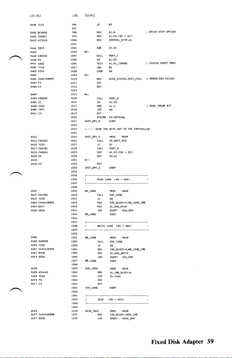
~
".--......,
~
LDC
DBJ
04QB
7215
0490
BFOSCD
04AO
268AOI
04A3
A27600
04A6
28e9
04A8
04A8
E80302
04A6
EC
04AC
ABOl
04AE
7509
0480
E2F6
0462
0482
C6D6740007
0487
F9
0488
C3
04B9
0489
E86502
04Bt
EC
0480
2402
04BF 7SF 1
04el
C3
04e2
04e2 E8C501
04C5
7207
04C7
E8A702
268M!
04CA
04CO
EE
04CE
04CE
C3
04CF
04CF
E81900
0402
7268
0404
C6064200E5
0409
6047
040B
EB68
0400
0400
E80BOO
04EO
7250
04E2
C6064200E6
04E7
6046
04E9
EB5A
04E6
04EB
A04600
04EE
3C80
04FO
'5
04Fl
C3
04F2:
04F2:
C60642:0009
04F7
EB30
SOURCE
LINE
996
997
99B
999
1000
1001
1002
65:
1003
1004
1005
1006
1007
1008
1009
83:
1010
1011
1012
1013
B6:
1014
1015
1016
1017
1018
1019
1020
1021
INIT_DRV_R ENOP
1022
1023
j
-----
1024
1025
INIT_DRY_S
1026
1027
1028
1029
1030
Dl:
1031
1032
1033
INIT_DRV_S
1034
1035
; --
1036
1037
;
---
1038
1039
RO
1040
1041
1042
1043
1044
1045
PO_lONG
1046
1047
j
------- - - ----------------
1048
1049
; -
1050
1051
"'"
1052
1053
1054
1055
1056
1057
WR
1058
1059
CHK
1060
1061
1062
1063
1064
CHK
1065
1066
1-
1067
1068
;
----------------------
1069
1070
DISK_SEEK
1071
1072
JC
MeV
MOV
AL,ES:[BX + Dll
MOV
CONTROL_BYTE
eX,ex
SUB
CALL
IN
Al,DX
TEST AL,Rl_IOMOOE
JHZ
LOOP
NOV
STC
RET
CAll
IN
.NO
JNZ
.3
RET
ASSUME
SEND THE BYTE
CALL
JC
01
CALL
MOV
OUT
RET
--------
----
-
READ
LONG
--
----
--
-
---
_LONG
CALL
JC
NOV
MOV
JMP
WRITE
----------
_LONG
-
-
-
-------
LONG
--------------
CALL
JC
MOV
MOV
JMP SHORT OHA_OPN
LONG
LONG
MOV
CMP
CMC
RET
LONG £NOP
- - - - -
---------------------------
(AH
SEEK
MOV
CMD_BLOCK. SEEK_CMD
JMP
SHORT
B3
01,8
.Al
POPT
1
-
B6
B5
DISK_STATUS,
PORT_O
AL,DX
Al,2:
E5:NOTHING
PROt
HD_WAIT_PEQ
PORT_O
AL,ES:[BX
OX,AL
ENOP
---
---------
PROC
CHK_lONG
G8
CMD_BLOCK +0
AL.O:1A_REAO
SHORT ONA_OPH
ENOP
PROC
CHK
G8
CMD_BlOCK+O .WR_LONG_CHD
AL,ONA_WRITE
ENOP
PROC NEAR
AL,CMD_BLOCK-+4
AL,080H
PPOC
OUT
TO
NEAP
---
---
-
(AH
::;
OAHl
----------
NEAR
{AH = 06H}
NEAR
LONG
-
= OCH)
-------
NEAR
NDMA_O?N
INIT
_FAIL
THE
CONTROLLER
...
01
J
---
------------
--
,RO_lONG_tHO
----
-----------
---------------
------- -
;
OR
IVE
;
STATUS INPUT
,
OPERATION FAILED
;
MASK
----
---
STEP
ERROR
OPTION
HOOE
BIT
Fixed Disk Adapter
39

LaC
04F9
04F9
04FE
0503
0505
0507
0507
osoe
0511
0513
0515
0515
OSiA
051C
OSlC
0521
0523
0523
0528
052A
052A.
052F
0531
0531
0536
0536
0538
0536
0530
OBJ
C60642000E
C&06460001
B047
EB3E
C60642000F
C&06460001
9046
E630
C606420000
EBIA
C606420001
EBl3
C6064200EO
ESOC
C6064200E3
EB05
(6064200E4
B002
E82700
7221
EB16
LINE
SOURCE
1073
1074
1075 ; -----------------------
1076
1077 ; -----------
1078
1079
1080
1081
1082
1083
1085
1086
; - - - - - - - - - - -
1087
1088
; - -
1089
1090
1091
Ion
1093
1094
1095
1096
1097
1098
1099
1100
1101
1102
1103
1104
1105
1106 ; ------------------------------------------------
1107
1108 ; ------------------------------------------------
Il09
lIlO
III
1112
1113
1114
1115 ; --------------------------------------------------------
1116
1117 ; --------------------------------------------------------
1118
1119
ll20
1121
1122
1123
1124 ; ------------------
1125
1126 ; ------------------------------------------------
1127
1126
1129
1130
1131
1132
1133 ; ----------------------------------------------------------
1134
1135
1136
1137
1138
----
10m_BUFF
""_BUff
1------------------
1-----------
TST_POY
TST
_ROY
1
RAN_DUG
CHK_DRV
CHK_DRV
1----------------------------------------------------------
1139
1140
1141 ; --------------------------------------------------------
1142
1143
; - - - - - - - - -
1144
1145
1146
1147
1148
1149
ENDP
-
READ
SECTOR
- - -
HOV
HOV
HOV
Jf1P
---------
WRITE
------------------------------------
?ROC
HOV
HOV
MOV
JHP
ENDP
TEST
DISK
----
PROC
I10V
JNP
ENOP
PECALIBRATE (AH =
HOV
JHP
CONTROLLER
HOV
JMP
DRIVE DIAGNOSTICS (AH =
PROC
NOV
JMP
EHOP
CONTROLLER
HOV
------------------
CALL
JC
JMP
---------
BUFFER (AH = OEH)
-.-
- - - - - - -
----
CHO_BLOCK+O,RD_BUFF_CMD
CHO_BLOCK+4.1
AL.ONA_READ
SHORT
DMA_OPN
---
- - -
SECTOR
---
BUffER
NEAR
CHO_BLOCKt4.1 ;
ALIONA_WRITE
-------------------
READY
(AH = OIOH)
---
----
-------
NEAR
CMD_BLOCKtO. TST_ROY_CI1[)
SHORT
NOMA_OPN
OllH)
PROC
NEAR
cm_BLOCK
.RECAL_cm
SHOPT
NOMA_OPN
EHDP
RAM
DIAGNOSTICS (AH =
PIWC
NEAP
CMD_BLOCK
to,
RAM_DIAG_CHO
ENDP
- -
----
- - - - - -
NEAR
CHO_BLOCKtO.CHK_ORV_CMD
SHORT
HOMA_OPN
INTERNAL DIAGNOSTICS (AH =
PROC
NEAP
CMD_BLOCKtO .CNTLR_OIAG_CMO
ENOP
SUPPORT
ROUTINES
--------------
AL.02H
COMHAND
Gll
SHORT
G3
---------------
---------------
----------------
(AH =
OFH
1
-----------
-------------------
-----
-----
013Hl
I
ONLY
- - - -
ONLY
012Hl
--------
- -
; ISSUE
-----
ONE
BLOCK
---
--
ONE
BLOCK
014H)
---
-------
---
THE
COMMAND
40
Fixed Disk Adapter

LOC
OBJ
D53F
053F
C606740009
0544
C3
0545
0545
£85701
0548
72F5
054A
6003
054C
f81300
054F 7200
B003
0551
0551
E60A
0555
0555
E421
0557
240F
0559
£621
055B
fSAAOl
055E
055E
E83BOO
0561
C3
0562
0562
BE4200
0565
£81802
0568
EE
0569
£81e02
05&C
EE
0560
2.8C9
056F
f80C02
0572
0572
EC
0573
240F
0575
!COD
0577
7409
0579
E2F7
0578
C606740080
0580
F9
0581
t3
0582
0582
FC
0583
690600
0586
E8E80 1
0586
0589
At
EE
058A
ElF9
058B
0580
E8EE01
0590
EC
0591 A801
0593
7406
0595
(606740020
059A
F9
0598
(3
059B
LINE
SOURCE
1150
OS'
1151
1152
1153
1154
1155
1156
1157
1158
1159
1160
1161
1162
1163
1164
1165
1166
1167
1168
1169
1170
1171 i
1172
1173
1174
1175
1176
Il77
1I7S
1179
1160
1181
1182
li8!
1184
1185
1186
1187
1188
1189
1190
1191
1192
1193
1194
1195
1196
1197
1198
1199
1200
1201
12.02
1203
1204
1205
1206
1207
1208
1209
1210
1211
1212
1213
1214 ; ---------------------------------------------1215
1216
1217
1218
1219
1220
1221
1222
1223
1224
1225
122:6
HOV
RET
DHA_OPH:
CALL
JC
HOV
CALL
JC
HOV
OUT
&3:
IN
At.,
OUT
CALL
&11:
CALL
RET
i -~--
~~------
COI1t1ANO
THIS ROUTINE OUTPUTS
; ItlPUT
AL =
;
------------
Cott1AUD
PRQC
I10V
CALL
OUT
CALL
OUT
SUB
eAlL
WAIT_BUSY:
IN
ANO
CHP
JE
LOOP
HOV
STC
RET
CI:
ClO
HOV
CM3:
CALL
loose
OUT
lOOP
CALL
IN
TEST
JZ
HOV
STC
CM7:
RET
COMMAND
ENDP
; BYTE a
BIT
BIT
BITS
BITS
; BYTE 1
BITS
BIT
BITS
o
15K_5T
ATUS, DMA_BOLtmARY
DHA_SETUP
G8
Al,03H
COMMAND
GIl
AL,OlH
DHA+IO.Al ;
AL,021H
AL,ODFH
021H
,Al
WAIT_IHT
ERROR_CHK
------------------------.
CONTROLLER
OI1A/INTERRUPT REGISTER
___________________________________________
NEAR
SI.OFFSET
PORT_2:
OX
,Al
PORT_3
DX,Al
eX,ex
PORT_l
AL.OX
AL,OFH
AL,Rl_BUSY
CI
WAIT_BUSY
DISK_STATUS. TIME_OUT
ex
,6
PORT_O
DX
••U
eM,
PORT_1
Al,DX
AL,RI_REQ
CH'
OISK_STATUS.8AD_CUTlR
SENSE
STATUS
AOORESS
SPARE. SET
5-4
ERROR
ERROR
ZERO
5 DRIVE
HEAD
TYPE
eODE
NUMBER
3-0
7-6
4-0
THE
Ct1J_BLOCK
OR
Rt_BUS
BYTES
VALID,
TO
[0-1)
-------------------
COMMAI-ft)
OR
WHEN
ZERO
; SET
ISSUE
INITIALIZE
BLOCK
;
CONTROLLER
; WAIT
;
GET
Rl_REQ
ERROR
I
i BYTE
;
GET
;
OUT
;
DO
; STATUS
SET
UP
MASK
eOUNT
STATUS
COUNT
THE
IT
MORE
FOR
TIlE
RETURN
NEXT
GOES
OMA
OPERATION
COMNAND
THE
DISK
_
SelECT
COI't1AtI) BYTE
CHANNEL
PULSE
Fixed Disk Adapter 41

LOC
DBJ
059<
OS?C
A07400
OS9F
OACO
05Al
7501
05A3
C3
05,6,4
05A4
984000
05A7 8Eeo
05A9
2BCO
05A8
88F8
05AO
C606420003
0582
2ACO
0584
E8ABfF
0587
7223
0589
890400
osse
osse
E8CBOO
OSBF
7220
OSCI E8AOOI
05C4
fC
05C5
26884542
05C9
47
05CA
E8B101
05CD E2EO
05CF
E8B800
0502
7200
0504
E89AOI
0507
EC
0508
A802
050A
740F
05DC
OSDC
C6067400FF
05EI
05El
F9
05E2
C3
05£3
lA06
05E5
2706
05E7
6A06
05E9
7706
05EB
05EB
268A1E4200
05FO
8AC3
05F2
24OF
05F4
80£330
05F7
2AFF
05F9
BI03
05FS
o3ES
05FD
2EFFA7E30S
0602
0602
00204020800020
0609 0040
0009
060B
0606
1010020004
0610
400000110B
OOOA
0615
0615 0102
LINE
1227
1228
; BYTE 2
1229
InO
1231
1232
; BYTE 3
1233
1234
i
1235
1236
1237
ERROR_CHK
1238
1239
1240
1241
1242
1243
1244
;-----
1245
}246
G21:
1247
1248
1249
1250
1251
1252
1253
1254
1255
1256
62:2:
1257
1258
1259
1260
1261
1262
1263
1264
1265
1266
1267
1268
1269
1270
1271
SENSE_ABORT:
1272
12:73 G2:4:
1274
1275
1276
ERROR_CHK
1277
1278
T_'
12:79
T_l
1280
T_2
1281
T_'
1282
12:83
STAT_ERR:
1284
1285
1286
1287
1288
1289
1290
1291
1292
1.:'93
1294
TYPEO_ TABLE
1295
1296
1297
TYPEO LEN
TYPE
1298
1299
1300
1301
TYPEl
1302
TYPE2_TABLE
1303
SOURCE
BITS
BITS
BITS
-----
- -
---------
ASSUME
MOV
JNZ
RET
PERFOPt1 SENSE STATUS
MOV
I10V
SUB
ItOV
MOV
SUB
CALL
JC
MOV
CALL
JC
CALL
IN
MOV
INC
CALL
LOOP
CALL
JC
CALL
IN
TEST
JZ
MOV
STC
RET
OW
OW
OW
OW
MOV
MOV
AND
ANO
SUD
MOV
SHR
JMP
ASSUME
D.
D.
I_TABLE
D.
D.
LEN EOU
-
D.
7-5
CYLINDER
4-0
7-0
PROC
ES:DATA
Al.DISK_STATUS
AL,Al
621
AX.OATA
ES,AX
AX,AX
DI.AX
CMD_BLOCK+O.SENSE_CI1D
AL.Al
COMMAND
SENSE_ABORT
eX.4
HO_WAIT]EQ
G24
PORT_O
.H,OX
ES:HO_ERROR t
OI
PORT_l
622
HD_WAIT_REQ
624
PORT_O
AL,DX
AL.2
STAT_ERR
DISK_STATUS
ENDP
TYPE_O
TYPE_I
TYPE_2
TYPE_3
BL.ES:HD_ERROR
AL,SL
AL,DFH
BL.OOllOOOOB
BH,BH
CL.3
BX,CL
WORD
ES:tIDTHING
LABEL
0,
O,BAD_SEEK
EOU
LABEL
BAD_ECC. BAD_ECC,
BAD_SEEK.
LABEL
BAO_CMO
HIGH
SECTOR NUMBER
CYlINDER
LOW
________________________________
NEAR
01
I,AL
.SENSEJAI
PTR
CS:[BX"
BYTE
BAO_CNTLR • BAD_SEEK
$-TYPEO_TABLE
BYTE
BAD _ADDR_HARK.
0.0
.DATA_CORRECTED
$-TYPEI_TABLE
SYTE
.SAD_AOOR_MARK
L
OFFSET
.BAD_CNTLR.
I
CHECK
ESTABLISH
i
ISSUE
;
CANNOT
; STORE
;
GfT
;
ISOLATE
; ADJUST
T_OJ
,BAD_TRACK
IF
THERE
SEGMENT
SENSE STATUS
RECOVER
AWAY
SENSE BYTES
ERROR
BYTE
TYPE
TINE_OUT
0,
RECORD
WAS
AN
COHHAND
I 0 I BAD_CNTLR
JIOT
_FNO
ERROR
42 Fixed Disk Adapter

LaC
OBJ
LINE
SOURCE
~
~
~
0002
0617
0617
202:010
0003
0610\
061"-
8B0206
0610
3C09
061F
7363
0621 2E07
0623
A27400
0626
C3
062:7
0627
B80B06
062:A
8ace
062:e 3eOA
062:E
7354
0630
2ED7
0632
...
27400
0635
80EI08
0638
80F908
0638
752A
0630
C606420000
0642
2ACO
0644
E81BH
0647
721E
0649
E83EOO
064C
7219
064E
E82001
0651
EC
0652
8AC8
0654
E83300
0657
720E
0659
£81501
065C
EC
0650
MOl
065F
7406
0661
C606740020
0666
F9
0667
0667
8ACI
0669
C3
066A
066A
BB1506
0660
3C02
066F
7313
0671
2ED7
0673
A27400
0676
C3
0677
0677
B81706
067A
X03
067C
7306
06n
ZED7
D680
A27400
0683
C3
0684
0684
C6067400B8
0689
C3
068A
066A
51
1304
1305
1306
1307
1308
1309
1310
1311
131Z
1313
1314
1315
1316
1317
HlB
1319
H2O
132:1
1322-
1323
1324
1325
1326
1327
J328
1329
1330
1331
1332
1333
1334
1335
1336
1337
n~8
1339
1340
1341
13421343
1344
1345
1346
1347
1346
1349
1350
1351
1352
1353
1354
1355
1356
1357
1358
1359
1360
.36'
1362
1363
1364
1365
1366
1367
."'.
1369
1370
1371
1372
1'373
1374
1375
B76
1377
1378
1379
1380
TYPE2_LEH
TYPE3_
TABLE
DB
TYPE3_LEN
;
-----
TYPE 0 ERROR
TYPE_O:
I10Y
CI1P
JAE
XlAT
HOY
RET
;
------
TYPE
TYPE.l:
""Y
MOY
C"P
J'E
XLAT
"DY
.NO
CHP
J"Z
,-----
OBTAIN
HDY
SUB
CAll
JC
CAll
JC
CALL
'"
MeY
CAll
JC
CALL
IN
TEST
JZ
MOY
STC
G30:
MDV
RET
;
-----
TYPE 2
TYPE_2 :
MOY
C"P
JAE
XLAT
"DV
RET
1-----
TYPE 3
TYPE_3.
HOY
CHP
JAE
XLAT
tIOY
OET
UHOEF
_ERR_L:
HDV
RET
HD_WAIT_REQ
PUSH
$-TYPEZ_TABLE
EOU
LABEL
BYTE
BAD_CNTLR
,BAD_CNTUl.BAD_ECC
$-TYPE3_TABLE
EOU
eX.OFfSET
TYPED_TABLE
.H,
TYPED.
LEN
UNDEF
.ERR.L
CS:TYPEO_TABLE I
DISK_STATUS,AL ; SET
I
ERROR
eX,OFFSET TYPEl.TABlE
eX,AX
AL,TYPEl.LEN
UNDEF
.ERR.L
CS:TYPEl.TABLE
DISK.STATUS,Al ;
CL.08H
el,08H
G30
ECC
ERROR
BURST lENGTH
CND_BlOCK +0 ,RD_ECC_CHO
AL.Al
COMMAND
G30
HO_WAlT_REQ
&30
PORT
•
Al,OX
CL,Al
HD_IoIAIT_REQ
GlD
PORT_O
AL,OX
AL,OIH
.,.
DISK_STA
TUS
,BAD_Ct-n'LR
.n,el
ERROR
eX,OFFSET
TYPE2_TABlE
Al,
TYPE2_LEN ;
UNDEF
_ERR_l
CS;TYPEl_TABlE
DISK_STATUS,Al
ERROR
BX,OFFSET
TYPE3_TABlE
AL,
TYPO_LEN
UNOEF
_ERR_l
CS:TYPE3_TABLE
DISK_STATUS,AL
DISK_STATUS , UNDEF
PROC
CX
_ERR
NEAR
I
CHECK
TABLE
;
CHECK
; TA8lE
SET
;
CORRECTED
CHECK
; TABLE
I SET
IF
LOOKUP
ERROR
IF
LOOKUP
ERROR
IF
LOOKUP
ERROR
ERROR
CODE
ERROR
CODE
ECC
ERROR
CODE
IS
IS
IS
DEFINEO
DEFINED
DEFINED
Fixed Disk Adapter 43

LOC
OSJ
0688
28C9
0680
EBEEOo
0690
0690
EC
0691
A801
0693
7508
0695
E2F9
0697
C606740080
069C F9
0690
0690
59
069E C3
069F
069F
SO
06AO
"'04600
06A3 3e81
06A5
58
06A6
1202
06A8
F9
06A9
C3
06AA
OUA
51
06A8
FA
06AC E60C
D6AE
50
58
06AF
06BO
HOB
06B2
8CCO
06B4
8104
0686
03CO
0688
8AE8
06BA 24FO
06Be
O3e3
06BE
7302
06CO
FEC5
06C2
06C2
50
06C3 E606
06C5 8AC4
06C7
E606
06C9 8AC5
240F
06CB
06CD E682
D6CF
A04600
0602
ODED
0604
FEce
0606
8AEO
0608
BOFF
060A
50
060B
A04200
060E 3CE5
7407
06EO
o6E2 3CE6
7403
o6E4
58
o6E6
06E7
EBll
o6E9
o6E9
58
06EA
B80402
06ED
53
LINE
SOURCE
1381
1382
1383
1384-
1385
1386
1387
1388
1389
1390
139.
1392
1393
1394
1395
1396
1397
1398
1399
1400
1401
140,
1403
1404
1405
1406
1407
1'+06
1409
1410
1411
1412
1413
1414
1415
1416
1417
1418
1419
1420
1421
1422.
1423
1424
1425
1426
1427
1428
1429
1430
1431
1432
1433
1434
1435
1436
1437
1438
1439
1440
1441
1442
1443
1444
1445
1446
1447
1448
1449
1450
1451
1452
1453
1454
1455
1456
1457
sue
eX.ex
CAll
ll:
L2:
HD_WAIT_REQ
;--------------------------------------------------------
; OHA_SETUP
INPUT
;
OtITPUT
;--------------------------------------------------------
DHA_SETUP
Jl:
J33:
,------
;-----
ADD4:
PORT_I
IN
AL.OX
TEST
AL,Rl_REQ
JNZ
L2
LOOP
L!
HOV
DISK_STATUS,
STC
pop
CX
RET
ENDP
THIS
ROUTIHE SETS
(Al)
:;::
HODE
tES:BX)
(AX)
PUSH
MOV
CMP
POP
JB
STC
RET
PUSH
CLI
OUT
PUSH
POP
OUT
MOV
MOV
ROL
MOV
ANO
ADO
JNC
INC
PUSH
OUT
I10V
OUT
MOV
AND
OUT
DETERMINE
HOV
SHL
DEC
HOV
HOV
HAHOlE
PUSH
MOV
CMP
JE
CMP
JE AD04
POP
JMP
POP
MOV
PUSH
BYTE
:;::
ADDRESS
DESTROYED
PROC
AX
Al,CtIJ_BLOCK+4
Al.8tH
AX
JI
CX
DMA+12,AL
AX
AX
DMA+ll.AL
AX,ES
CL,4
AX,CL
CH.AL
AL.OFOH
AX,BX
J33
CH
AX
DI1A+~HAL
ALtAH
DMA+6,AL I
AL,CH
AL.OFH
DHA_HIGH.AL ;
COUNT
AL.CHD_BLOCK+4
AL.!
AL
AH,AL
AL,OFFH
READ
AND
AX
AL.CHD_BLOCK+O ;
Al.RD_LONG_CHD
ADM
AL.WR_lONG_CtIJ
AX
SHORT
AX
AX.516D
BX
FOR
NEAR
WRITE
J'O
TIME_OUT
UP
FOR
THE
TO
READ/WRITE
LONG
OMA
OPERATIONS.
OM"
(5160
THE
DATA
;
BLOCK
COUNT
;
SAVE
THE
i
NO
MORE
i SET
THE
;
OUTPUT
THE
;
GET
THE
;
SHIFT
COUNT
I
ROTATE
LEfT
GET
HIGHEST NYBBLE
;
ZERO
THE
;
; TEST
FOR
j
CARRY
MEANS
I
SAVE
START
;
OUTPUT
LOW
OUTPUT
HIGH
GET
HIGH 4
;
OUTPUT
THE
RECOVER
I
; MULTIPLY
AND
DECREMENT
BYTE BLOCKS)
;
SAVE
REGISTER
GET
COHMAND
i
RESTORE
;
RESTORE
lONE
BLOCK
OUT
REGISTER
INTEIi'RUPTS
FIRST/LAST
HODE
ES
VALUE
LOW
NYBBLE
CARRY
HIGH 4
ADDRESS
ADDRESS
ADDRESS
BITS
HIGH 4
BLOCK
COUNT
BY
512
REGISTER
REGISTER
(512)
OF
BYTE
FROM
BYTES
VALUE
PLUS
RANGE
F/F
OF
FROM
ADDITION
BITS
BITS
4 BYTES
ES
BY
TO
PER
TO
SEGMEHT
I'n)ST
PAGE
SECTOR
ONE
CH
BE
INC
REG
ECC
44
Fixed Disk Adapter

r""\
~
r""\
LaC
OBJ
06EE 2AFF
D6FO
8AIE4600
06F4 52
06f5
F7E3
OOF7
SA
06F8
58
06F9
48
D6FA
06FA
50
06F8
E607
D6FD
8AC4
D6FF
E607
0701
F8
0702
S9
0703
58
0704
03el
0706
S9
0707 C3
0708
0708
FB
0709
53
070A 51
070B 06
070C 56
0700
IE
070E 2Beo
0710
8E08
0712
C4360401
0716
IF
0717
UFF
0719
268A5C09
071D
8A264200
0721 80FC04
0724 7506
0726 268A5cOA
072A EB09
072C 80FCE3
072F 7504
onl
268A5C08
on5
on5
28C9
on7
on7
E84400
OnA
EC
onB
2420
onD
3e20
073F 740A 1521
0741 E2F4 1522
0743
48
0744
75Fl
0746
C606740080
074B
0748
E82300
074E
EC
074F 2402
0751
08067400
0755
E83000
0758
32CO
075A
EE
075B
5E
1458
1459
1460
1461
1462
1463
1464
1465
1466
1467
1468
1469
1470
1471
1472
1473
1474
1475
1476
1477
1478
1479
1480
1481
1482
1483
1484
1485
1486
1487
1488
1489
1490
1491
1492
1493
1494
1495
1496
1497
1498
1499
1500
1501
1502
1503
1504
1505
1506
1507
1508
1509
1510
1511
1512
1513
1514
1515
1516
1517
1518
1519
1520
1524
1529
1530
1531
1532
1533
1534
LINE
SOURCE
BH,BH
SLOl
BL,eHD_BLOCK
NOV
PUSH
OX
BX
MUL
pop
OX
PDP
BX
DEC
J2:0:
DHA_SETUP ENIlP
;------------------------------------------------
I WAIT_INT
;------------------------------------------------
IoIAIT_I
;
-----
1015:
..
,
1-----
loll:
1523
1525
1012:
1526
1527
1528
AX
PUSH
AX
OUT
OMA+7,Al
MOV
AL,AH
OUT
DMA+7,Al ;
STI
POP
CX
POP
AX
ADD
AX.CX ;
POP
CX
OET
THIS
ROUTINE WAITS
CONTROLLER
HAS
OCCURRED.
NT
PROC
STI
PUSH
BX
PUSH
CX
PUSH
ES
PUSH
SI
PUSH
OS
ASSUt1E
DS:DlJt1HY
SUB
AX,AX
MOV
DS,AX
LES
SI,HF.TBL.VEC
ASSUME
DS:DATA
POP
OS
SET
TIMEOUT
BH,BH
SUB
BL,BYTE
MOV
I10V
AH.CI'IJ.BLOCK
CMP
AH,FMTDRV.CI1D
JHZ
H5
MOV
BL.BYTE
JMP
SHORT
CMP
AH. CHK.DRV.CMD
JHZ
H'
MOV
BL.BYTE
SUB
CX.CX
WAIT
FOR
INTERRUPT
CALL
PORT. 1
IH
AL.DX
AL.020H
AND
CMP
AL.020H
JZ
H'
LOOP
HI
DEC
BX
JHZ HI
MOV
DISK.STATUS. TIME.OUT
CALL
IN
AL.DX
ANIl
AL,2
00
DISK.STATUS.AL
CALL
PORT.l
XOO
AL,AL
OUT
DX.Al
POP
SI
TO
VALUES
PORT.O
SIGNAL
NEAR
PTR
PTR
H'
PTR
..
4
FOR
THAT
ES:[SIJ(91
ES:(SIHOAHJ
ES:[SIJ[OBHI
THE
;
RETURN
AN
FIXED
INTERRUPT
I
BLOCK
COUNT
TIMES
J ADJUST
; SAVE COUNT VALUE
;
LOW
BYTE
OF
coUtIT
HIGH
BYTE
OF
TEST
CALLER,
ON
BACK
COUNT
FOR
REGISTER
CFl
Jt.ITERIWPTS
REGISTERS
SEGMENT
;
STANDARD
;
FORMAT
I
CHECK
lOOP
lOOP
8Il
MASK
MASK
REGISTERS
COUtIT
; INTERPUPTS
;
RECOVER
j RECOVER ADDRESS
ADD.
j PECOVER
TO
DISK
;
TURN
;
PRESERVE
; ESTABLISH
; DID INTERRUPT
; INNER
i
OUTER
ERROR
SAVE
INTERRUPT
;
ZERO
I
RESET
I
RESTORE
516
m~
VALUE
VALUE
641<
OVERFLOW
SET
BY
TIME
DRIVE
DRIVE
OCCUR
REGISTER
ABOVE
OUT
IF
ERROR
Fixed Disk Adapter 45

LOC
07se
0750
07SE
075F
0760
0760
0761
0763
0765
0767
0769
0768
0760
076F
0770
0771
0771
0774
0775
0777
077A
017e
0770
077E
077E
0781
0782
0783
0763
0786
0787
0786
0788
0785
a7ac
0780
0760
0790
0791
0792
0795
0796
0796
0799
0796
079F
07A2
07,6,4
07A6
07A8
07A8
07AA
OBJ
07
59
58
C3
SO
B020
f620
B007
£60A
E421
OC20
E621
58
CF
BA2003
50
2"E4
A07700
0300
58
C3
ESFOFF
42
C3
E8F8FF
42
C3
EBF8FF
42
C3
E6F3FF
EC
50
E8E9FF
EC
2402
58
7516
8A264300
80E42:0
7S0ct
00E6
00E8
2403
8104
LINE
SOURCE
1535
1536
1537
1536
1539
1540
1541
154~
1543
1544
1545
}546
1547
1548
1549
1550
1551
1553
1554 ; ----- - - - -- - -
1555
1556
1557
1556 ; ------------------1559
1560
1561
1562
1563
1564
1565
1566
1567
1566
1569
1570
1571
1572
1573
1575
1576
1577
1578
1579
1580
1581
158~
1583
1584
1585
1586
1587
1588 ; -------------------------1589
1590
1591
1592
1593 ; ------------.
1594
1595
1596
1597
1598
1599
1600
1601
1602
1603
1604
1605
1606
1607
1608
1609
1610
1611
pop
pop
pop
RET
HD_INT
PRQC
PUSH
HoV
OUT
HoV
OUT
OR
OUT
POP
IRET
PORTS
GENERATE
BASED
HoV
PUSH
SUB
HOV
.00
pop
RET
RET
PORT3 PROC
INC
RET
PORT_Z
EHOP
PORT_~
PROC
RET
PORT_3
ENDP
;
SW~_OFFS
DETERMINE
USING CONTROLLER
DRIVE
SW2_0FFS
CALL PORT_2
IN
PUSH
CALL PORT.1
IN
AND
POP
J"Z
HoV
AND
JNZ
SHR
SHO
SW2_AN):
'N!)
HOV
ES
CX
BX
EN!)P
NEAR
AX
AL.EOI
INT_CTl_PORT
AL.07H
DMA+IO.AL
AL.OZIH
AL.020H
021H.AL
AX
-----
______________________
PROPER
ON
THE
PORT
--
--------
AX
AH
.AH
OX,AX
AX
NEAR
OX
NEAR
PARAMETER
HUMBER
SPECIFIER
---------------
PROC
ALDX
AX
AL.DX
AL.2
AX
SW2_0FFS_ERR
AH.CMD_BLOCK+l
AH.OOIOOOOOB
SWZ_AND
AL.t
AL.I
AL.OllB
Cl.4
.AL
PORT
VALUE
OFFSET
__________
----
------------
TABLE OFFSET
PORT
TWO
(0-1)
--------------------
NEAR
AND
I
END
OF
I SET
DNA
_
_
; BASE VALUE
ADO
IN
; INCREMENT
I IHCREMEtfT
INCREMENT
------
;
READ
PORT
I
CHECK
FOR
; DRIYE 0
; ADJUST
I ISOLATE
IHTERRUPT
MODE
TO
TIfE
OF
TO
PORT
TO
TO
Z
ERROR
OR
1
FSET
PORT
PORT
DISABLE
ONE
TWO
THREE
46
Fixed Disk Adapter

~
lOC
OBJ
07Ae
OZED
07AE
2AE4
07BO
(3
0761
07Bl
F9
0782
(3
0783
30382F31362F38
"
07Em
1612
1613
1614
1615
1616
1617
1618
1619
1620
162:1
1622
1623
1624
LINE
SOURCE
Al,Cl
SHl
AH,AH
SUB
RET
SW2:_OFFS_ERR:
STe
RET
SW2_0FFS EHIlP
'08/16/82
DB
ENDS
END
LABEL
END_ADDRESS
CODE
•
BYTE
; ADJUST
;
PHEASE
HARKER
Fixed Disk Adapter 47

Notes:
48 Fixed Disk Adapter
 Loading...