

Page 1

IBM Fibre Channel
Basic SAN Configuration Setup Guide
Page 2

Page 3

IBM Fibre Channel
Basic SAN Configuration Setup Guide
Page 4

Note:
Before using this information and the product it supports, be sure to read the general information in ″Notices″ on page 25.
First Edition (August 2001)
© Copyright International Business Machines Corporation 2001. All rights reserved.
US Government Users Restricted Rights – Use, duplication or disclosure restricted by GSA ADP Schedule Contract
with IBM Corp.
Page 5

Contents
Preface ............................v
Who should read this book .....................v
How to use this book .......................v
Chapter 1. SAN solutions overview .................1
Building blocks .........................1
Configuration types ........................1
Basic storage partitioning ....................2
Cluster and non-cluster shared storage pool .............3
SAN with partitioned storage ...................4
High-capacity storage configuration .................5
Multiple clusters in a switched fabric environment ...........6
Direct attach multiple cluster configuration ..............7
Hardware components overview ...................7
Server ...........................8
Fibre Channel host bus adapter ..................8
Fibre Channel RAID controller enclosure unit .............8
Fibre Channel switch ......................9
SAN Data Gateway.......................9
Tapelibrary.........................10
Hard disk drive enclosure ....................10
Software programs overview ....................10
IBM FAStT Storage Manager software ...............10
Fibre Channel switch utility program ................11
Fibre Channel SAN router utility program ..............12
Storage management program ..................13
Chapter 2. Installation overview ..................15
Example SAN solution configuration .................15
Fibre Channel cable installation ...................15
Solutionbillofmaterials .....................16
Planning and installing devices in a rack cabinet ............17
Chapter 3. Installation sequence..................19
Chapter 4. Operation, maintenance, and scalability ..........21
Powering Sequence .......................21
Scaling capacity and change management...............21
Installing additional servers ...................21
Installing additional Fibre Channel host bus adapters ..........22
Installing additional drive enclosures ................22
Installing additional Fibre Channel switches .............23
Appendix. Notices .......................25
Edition notice .........................25
Trademarks ..........................26
© Copyright IBM Corp. 2001 iii
Page 6

iv IBM Fibre Channel: Basic SAN Configuration Setup Guide
Page 7

Preface
The IBM®SAN Solutions Basic Configuration Setup Guide outlines the steps
required to assemble a basic Storage Area Network (SAN) that encompasses IBM
SAN Solutions hardware components. Several possible configurations are also
described. In addition, this guide discusses how to add hardware components to
expand the SAN configuration. This guide is not intended to describe all the
configurations possible by using the building blocks listed in this chapter. The
installation information presented in this book is intended to be used in conjunction
with the detailed information found at the Web sites cited in the text.
Note: Many of the explanations of components and programs in this book are
directly quoted from the original IBM documentation for the particular
products. Because this guide is intended to serve as an outline for
assembling a SAN configuration, be aware that the original information
source will often contain more detail than this guide. Therefore, if you have
questions about particular components or programs, refer to the
documentation for the component or program.
Who should read this book
This guide is intended for trained service personnel who are familiar with IBM
products and are proficient with Windows
The user should have a solid understanding of the IBM FAStT Storage Manager as
well as the software tools used to configure and administer Fibre Channel switches,
routers, host bus adapters, and other hardware devices.
How to use this book
This book is organized as follows:
“Chapter 1. SAN solutions overview” on page 1, lists the major building blocks of a
SAN solution, describes the configuration that is the focus of this guide, and
presents an overview of the hardware components and software programs that
comprise the IBM SAN Solutions portfolio.
“Chapter 2. Installation overview” on page 15, introduces the type of SAN
configuration discussed in this guide and provides an overview of the installation
process.
“Chapter 3. Installation sequence” on page 19, provides a step-by-step sequence to
assembling a basic SAN configuration. These steps include verifying and updating
the basic server, Fibre Channel switch, host bus adapter, and router firmware, as
well as installing, configuring, and administering the hardware components.
“Chapter 4. Operation, maintenance, and scalability” on page 21, discusses the
operation and maintenance of a SAN and the process of adding components to a
SAN configuration.
®
2000 operating system administration.
© Copyright IBM Corp. 2001 v
Page 8

vi IBM Fibre Channel: Basic SAN Configuration Setup Guide
Page 9

Chapter 1. SAN solutions overview
The IBM SAN initiative provides a complete range of services, infrastructure, and
technology required to successfully implement a Storage Area Network (SAN).
Servers, storage devices, software, and Fibre Channel interconnect components are
the building blocks used to construct, use, and manage a SAN. Because of the
complexity of heterogeneous, multi-platform environments, service and system
integration are critical to the success of a SAN implementation.
Building blocks
The following building blocks are included in a typical SAN configuration:
v Operating systems
This guide details configurations using Microsoft
v Device configuration and management software programs and tools
This guide discusses programs to configure and manage switches, managed
hubs, redundant array of independent disks (RAID) controllers, host bus adapters
(HBAs), and SAN routers.
v Storage management applications
Applications to manage tape libraries and hard disk enclosures are included in
the IBM SAN Solutions configurations.
v Storage, HBAs, other options
This guide discusses hard disk drive enclosures, Fibre Channel (FC) HBAs, and
tape drives and libraries.
v Servers
®
Windows®2000.
This guide details configurations using IBM
v Fibre Channel interconnect
This guide discusses Fibre Channel switches and managed hubs, Fibre Channel
routers, Gigabit Interface Converters (GBICs), and Fibre Channel cables.
Configuration types
The following sample configurations are described in this chapter:
v Basic storage partitioning
v Cluster and non-cluster shared storage pool
v SAN with partitioned storage
v High-capacity storage configuration
v Multiple clusters in a switched fabric environment
v Direct attach multiple cluster configuration
xSeries servers.
© Copyright IBM Corp. 2001 1
Page 10
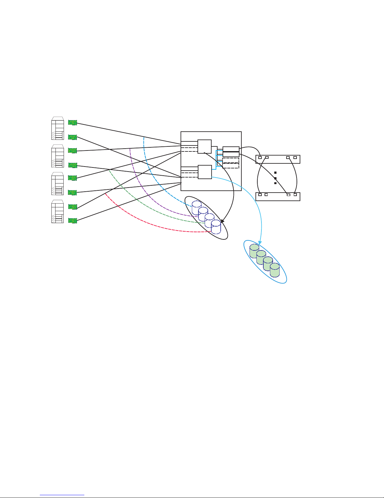
Basic storage partitioning
The following illustration shows the functionality of partitioning. Partitioning the
storage provides flexible management of available storage by subdividing the
storage into separate independent sections or partitions. It also enables you to
consolidate the storage from multiple host systems into one or more FAStT500
RAID Controller Enclosure Units and amortize the cost of the storage across the
connected hosts rather than having one host incur the total cost of the storage.
FC host adapter
To m
Jim
Bill
Al
FC host adapter
FC host adapter
FC host adapter
FC host adapter
FC host adapter
FC host adapter
FC host adapter
FAStT500 RAID controller unit
Host side
Mini-hub
Mini-hub
Mini-hub
Mini-hub
To m
Ctrl
A
Ctrl
B
Jim
Drive side
Mini-hub
Mini-hub
Mini-hub
Mini-hub
Bill
Al
Loop1
IN
IN
OUT
Loop1
EXP500
OUT
Loop2
IN
OUT
IN
OUT
Loop2
Figure 1. Basic storage partitioning
Note: Four partitions are shown. Eight are available in the base configuration.
2 IBM Fibre Channel: Basic SAN Configuration Setup Guide
Page 11
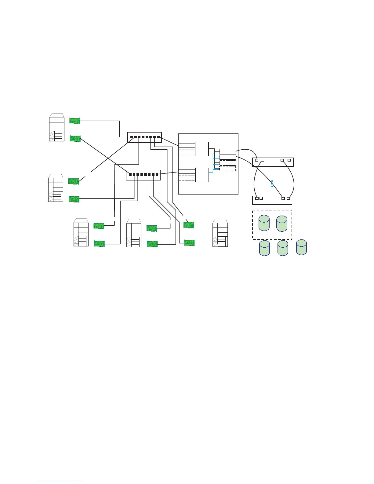
Cluster and non-cluster shared storage pool
The following illustration shows a configuration where both the clustered and
non-clustered servers share storage. This configuration increases reliability and
availability through redundancy of the Fibre Channel components, with no single
point of failure. Storage is defined for each of the server environments that use the
storage partitioning capability of the FAStT500 RAID Controller Enclosure Unit,
provided that each server is its own storage subsystem.
FC host adapter
FC host adapter
Clus1
FC host adapter
FC host adapter
FC host adapter
FC host adapter
Notes1
Managed Hub/Switch
Managed Hub/Switch
FC host adapter
FC host adapter
File 1
Figure 2. Cluster and non-cluster shared storage pool
Note: Factors such as performance and the number of storage partitions influence
the number and type of node.
FAStT500 RAID controller unit
Host side
Mini-hub
Mini-hub
Mini-hub
Mini-hub
FC host adapter
FC host adapter
Ctrl
A
Ctrl
B
Drive side
Mini-hub
Mini-hub
Mini-hub
Mini-hub
DB 1
EXP500
Loop1
IN
OUT
Loop1
IN
OUT
Clus1
1
LD1
2
Notes1
Partitions 1-4
LD2
3
File 1
Loop2
IN
Loop2
IN
OUT
OUT
4
DB 1
Chapter 1. SAN solutions overview 3
Page 12

SAN with partitioned storage
The following illustration shows a SAN with partitioned storage. SANs with
partitioned storage are separate, centrally managed, high-speed storage networks
which consist of a variety of storage hardware, storage management software, and
interconnect devices. SANs with partitioned storage can be configured to provide
hundreds of terabytes of shared storage across an enterprise. This configuration
heightens the level of availability and business continuity and optimizes use of
corporate LANs by providing a storage infrastructure designed specifically for
managing corporate information.
N
O
T
E
S
N
O
T
E
S
N
O
T
E
S
N
O
T
E
S
F
I
L
E
Servers
F
I
L
E
F
I
L
E
F
I
L
E
F
I
L
E
F
I
L
E
F
I
L
E
F
I
L
E
16 port Sw
Controller A
Controller B
Notes
Storage
Controller A
Controller B
Notes
Storage
Figure 3. SAN with partitioned storage
16 port Sw
Controller A
Controller B
File/Print
Storage
16 port Sw
Controller A
Controller B
File/Print
Storage
16 port Sw
Controller A
Controller B
File/Print
Storage
Controller A
Controller B
File/Print
Storage
4 IBM Fibre Channel: Basic SAN Configuration Setup Guide
Page 13

High-capacity storage configuration
The following illustration shows how the FAStT500 supports large, business-critical
applications for today’s e-business. Internet service providers, storage service
providers (SSPs), or any business that relies on highly scalable solutions will benefit
from a high-capacity storage configuration.
Fibre Adapter
Fibre Adapter
F1
FAStT500 RAID
enclosure
220 drives *36.4 GB = 800 GB (760 TB usable in 9 + 1 RAID 5)
F2
FAStT500 RAID
enclosure
15.2 TB usable total
Fibre Adapter
Fibre Adapter
Notes: Optimized for capacity, not performance
Drive redundant path not shown for clarity
220 drives *36.4 GB = 800 GB (760 TB usable in 9 + 1 RAID 5)
Figure 4. High-capacity storage configuration
Note: This configuration is optimized for capacity, not performance. For clarity, the
drive redundant path is not shown.
Chapter 1. SAN solutions overview 5
Page 14
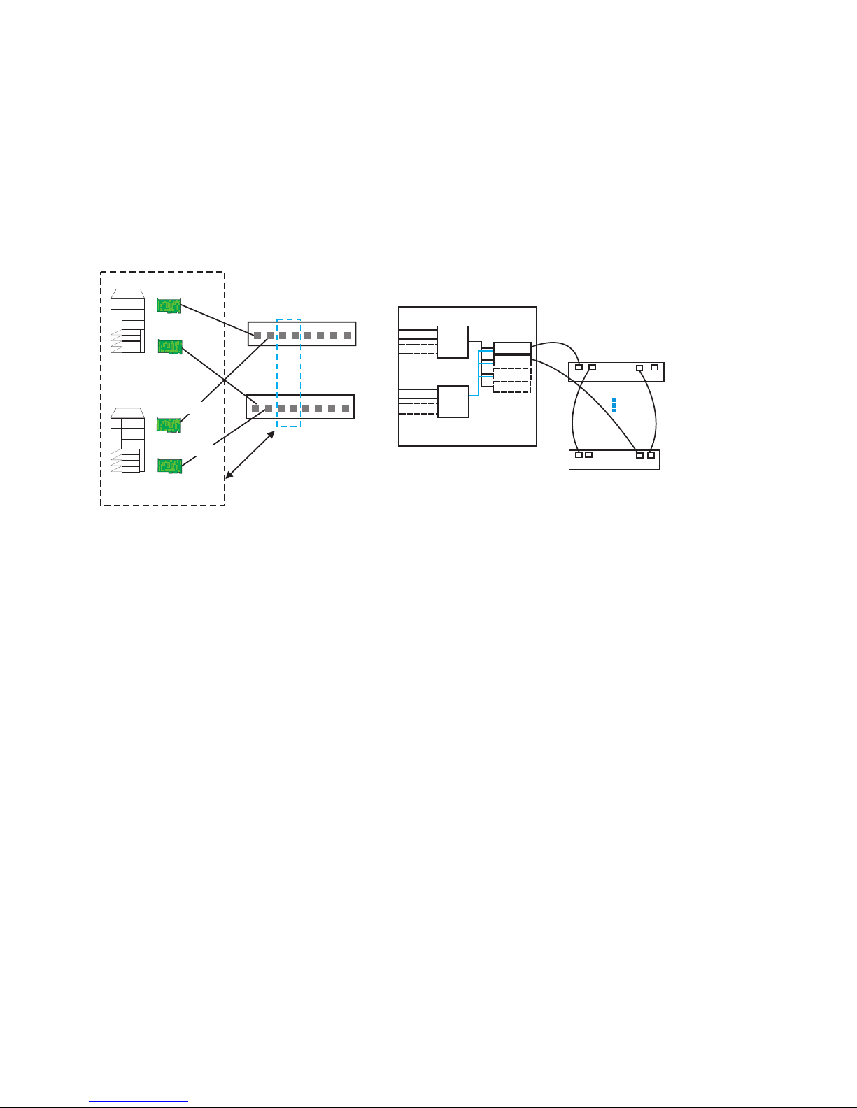
Multiple clusters in a switched fabric environment
IBM SAN Fibre Channel switches enable high-performance, highly scalable SAN
with multiple clusters to be created. The following illustration shows a SAN with
four-port grouping (for redundancy) supporting a two-node cluster that enables the
configuration to accommodate multiple clusters. This type of configuration helps
reduce downtime and enables unencumbered access to storage through
partitioning. Use of 16-port switches (versus the 8-port displayed in the figure) can
increase port count and the number of servers or FAStT500 RAID storage.
FC host adapter
FC switches
FC host adapter
FC host adapter
FC host adapter
FAStT500 RAID controller unit
Host side
Mini-hub
Mini-hub
Mini-hub
Mini-hub
Figure 5. Multiple clusters in a switched fabric environment
Note: Each group of four ports on the switches (gray dash box) can support one
cluster element (black dash box). Storage partitioning is used to separate
clusters. Sixteen port switches enable more clusters, provided this fits within
performance needs and available partitions.
Ctrl
A
Ctrl
B
Drive side
Mini-hub
Mini-hub
Mini-hub
Mini-hub
Loop1
IN
IN
OUT
Loop1
EXP500
OUT
Loop2
IN
IN
OUT
Loop2
OUT
6 IBM Fibre Channel: Basic SAN Configuration Setup Guide
Page 15

Direct attach multiple cluster configuration
This configuration shows multiple clusters connecting to a single FAStT500 RAID
Controller Enclosure Unit. It uses the pre-installed mini-hubs as a starter solution
with the option of adding additional FAStT500 mini-hubs and Fibre Channel
switches/managed hubs for added host and drive scalability.
FC host adapter
FC host adapter
Clus1
FC host adapter
FC host adapter
FC host adapter
FC host adapter
Clus2
FC host adapter
FC host adapter
Figure 6. Direct attach multiple cluster configuration
FAStT500 RAID controller unit
Host side
Mini-hub
Mini-hub
Mini-hub
Mini-hub
Ctrl
A
Ctrl
B
Drive side
Mini-hub
Mini-hub
Mini-hub
Mini-hub
Clus1
Clus2
Loop1
IN
IN
OUT
Loop1
EXP500
OUT
LD1
LD3
Loop2
IN
OUT
IN
OUT
Loop2
1
LD2
2
LD4
Note: Two partitions are shown; the Clus1 partition is separate from the Clus2
partition. LD is a logical drive.
Hardware components overview
This section provides an overview of the hardware components that comprise the
IBM SAN solution. New components are frequently added from the IBM portfolio or
third-party vendors.
The following hardware components are discussed in this section:
v Server
v Fibre Channel host bus adapter
v Fibre Channel RAID controller unit
v Fibre Channel switch
v SAN Data Gateway
v Tape library
v Hard disk drive enclosure
Chapter 1. SAN solutions overview 7
Page 16

Server
Note: Please refer to the product documentation to resolve any product-specific
questions.
The following lists IBM Servers that can be used in a SAN:
v IBM
xSeries mission-critical servers contain features that help deliver superior
performance and scalability. xSeries mission-critical servers deliver unmatched
performance and reliability through IBM X-architecture technology.
v IBM
These servers offer fast Intel
industry-leading performance benchmarks. Integrated features and bundled
software enhance the value and performance of these economical servers.
v IBM
xSeries value servers offer an affordable, off-the-shelf solution that provides a
high-quality design, craftsmanship, and bundled software.
v IBM
xSeries rack-optimized servers have ample room for expansion and options. For
heavy-duty computing capability in minimal space, xSeries rack-optimized servers
and options can help any organization that needs to maximize its computing
space.
xSeries mission-critical servers
xSeries price/performance servers
xSeries value servers
xSeries rack-optimized servers
Fibre Channel host bus adapter
The IBM FAStT Host Adapter is an intelligent, high-performance, direct memory
access (DMA) bus master host adapter designed for high-end systems. The
intelligence and performance of this leading-edge PCI adapter are derived from an
ISP2200A chip.
®
processors, excellent scalability, and
The ISP2200A chip combines a powerful RISC processor, a fibre protocol module
(FPM) with gigabit transceivers, and a 64-bit peripheral component interconnect
(PCI) local bus interface in a single-chip solution. The IBM FAStT Host Adapter is
compatible with all Fibre Channel peripherals that support private loop direct attach
(PLDA) and fabric loop attach (FLA).
Fibre Channel RAID controller enclosure unit
The IBM FAStT500 RAID controller enclosure unit provides dual, redundant
controllers with Fibre Channel interfaces to both the host and drive channels. The
controller unit has redundant cooling, redundant power, and battery backup of the
controller cache.
Designed to provide maximum host and drive side redundancy, the controller
enclosure unit supports direct attachment of up to four hosts containing two host
adapters each. Using externally managed hubs and switches in conjunction with the
RAID controller unit, you can build even larger configurations.
FAStT500 RAID Controller enclosure unit features include:
v Dual RAID controller units
v Support for up to 220 HDDs in a dual-loop
v Built-in fail-over protection; no single point of failure
v Two host and two drive mini-hubs included
8 IBM Fibre Channel: Basic SAN Configuration Setup Guide
Page 17

v Hot-plug for easy configuration
v Four additional slots available to support RAID levels 0, 1, 3, 5, 10
v 256 MB battery-backed cache
Fibre Channel switch
When using FAStT Storage Manager, you must have isolated paths to each
controller within the FAStT500 RAID Controller Enclosure Unit. This requires having
no inter-switch links (ISL) between the two 2109-S08 or 2109-S16 switches.
Prohibiting ISL is required because the Redundant Disk Array Controller (RDAC)
that is used by the FAStT Storage Manager software is not a multi-path driver and
can only failover between two paths.
The switch is a high-performance Fibre Channel gigabit switch with the following
features:
v Simple
It is easy to setup and configure. After Power-On Self-Test (POST), you only
need to add the switch’s Internet Protocol (IP) address. The remainder of the
switch setup is automated.
v Intelligent
The switch fabric operating system enables discovery of all connected devices
and determines optimum data paths without intervention, supporting up to 32
interconnected switches.
v Flexible
The switch contains multiple GBIC modules supporting fiber transmission media.
It’s modular design gives the switch a range of flexibility in creating, upgrading,
maintaining, and configuring a fabric.
v Reliable
Highly integrated, reliable, multifunction (ASIC) devices are used throughout the
switch.
v High performance
Low-latency, high-performance design enables a worst-case data-transfer latency
of less than two microseconds from any port at peak Fibre Channel performance
of 100 MB/sec. The latency may differ when the destination or device is a loop.
v Automated congestion management
Virtual channels enable the switch to use sophisticated congestion management
techniques automatically.
v Cascading
Switches can be cascaded for large fabric support.
v Universal
The switch ports are designed to support F, FL, and E-port modes of operation
with the software selecting the optimum mode of operation.
SAN Data Gateway
The SAN Data Gateway is an essential component of the SAN infrastructure. The
gateway integrates storage and networking interfaces through a number of different
technologies such as Fibre Channel point-to-point, Fibre Channel arbitrated loop,
and small computer system interface (SCSI).
The SAN Data Gateway connects an interface as either an initiator or a target. The
gateway is a fully scalable product with Fibre Channel and SCSI interface options.
Chapter 1. SAN solutions overview 9
Page 18

The gateway has up to four ultra SCSI channels and up to two SAN interfaces,
each configured using plug-in adapters. These interfaces, used for host or device
point-to-point and loop connections, create powerful SAN solutions.
The SAN Data Gateway data mover option enables server-free backup capabilities.
SAN Data Gateways can move data directly between attached storage devices
regardless of storage type. Data mover frees up system resources and substantially
increases the speed of tape backup and restore operations.
Tape library
Many tape libraries can be used in a SAN configuration. Refer to the
http://www.pc.ibm.com/ww/eserver/xseries/serverproven/index.html Web page for
compatibility with your hardware.
Hard disk drive enclosure
IBM FAStT EXP500 features include:
v Full Fibre Channel support
v Support for up to 10 high-speed Fibre Channel connections
v Fully redundant base unit
v Hot-plug redundant power supplies and fans
v Support for converged carrier HDDs
IBM Hot-Swap HDD features include:
v 9.1 GB and 18.2 GB slim, 10k-3 rpm
v 36.4 GB half-high, 10k-3 rpm
Software programs overview
This section provides an overview of the programs that comprise the IBM SAN
solutions. New components are frequently added from the IBM portfolio or from
third-party vendors.
The following software components are discussed in this section:
v IBM FAStT Storage Manager software
v Fibre Channel switch utility program
v Fibre Channel SAN router utility program
v Storage management program
Note: Refer to the product documentation to resolve any product-specific
questions.
IBM FAStT Storage Manager software
IBM FAStT Storage Manager 7.x is a Java-based tool that simplifies the
management of the IBM Fibre Array Storage Technology (FAStT)500 RAID
Controller Enclosure Unit. This software provides an interface for storage
management based on information supplied by the storage subsystem controllers.
Storage Manager 7.x contains the following software components:
v Client software
10 IBM Fibre Channel: Basic SAN Configuration Setup Guide
Page 19

The Storage Manager 7.x client (SM7 client) component provides the graphical
user interface for managing storage subsystems through an Ethernet network or
a host connection.
The SM7 client contains two main components:
– Enterprise Management for adding, removing, and monitoring storage
subsystems within the management domain.
– Subsystem Management for managing the components of an individual
storage subsystem.
v Host-agent package
The Storage Manager 7.x agent (SM7 agent) consists of two software
components:
– Host-agent software
The host-agent software answers requests made to the host server over the
network and routes those requests to the storage subsystem over the Fibre
Channel link.
– Storage Manager 7 devices utility
The SM7devices utility enables you to associate storage subsystem logical
drives with operating system device names.
v RDAC package
The Redundant Disk Array Controller (RDAC) package consists of two software
components:
– RDAC multipath device driver
The RDAC multipath device driver provides failover support to the other
controller if a component along the I/O path fails.
– Hot-Add utility
The Hot-Add utility enables you to register newly created logical drives with
the operating system (this feature is only available in Windows NT
®
4.0).
Fibre Channel switch utility program
The IBM StorWatch Specialist enables users to remotely monitor and manage a
Storage Area Network (SAN) of switches using a Java-capable Web browser from a
standard desktop workstation. You can dynamically interact with any switch in the
SAN to monitor status and performance. By using the information provided, you can
manage overall topology or make administrative changes to switches or the
network.
The IBM StorWatch Specialist provides the following capabilities:
v Central status monitoring
From the Fabric View, display all switches in a fabric on a single screen and
access detailed switch information or administer any switch in the SAN.
v Rapid access to any switch
From the Fabric View, click on a switch icon to access switch status, port status,
throughput, performance, and operating conditions such as temperature or fan
and power supply status.
v Comprehensive asset management
From the Name Server Tables, get detailed information on all SAN devices in the
fabric.
v Extensive administration and configuration capability
Chapter 1. SAN solutions overview 11
Page 20

Configure and administer individual ports or switches through a wide range of
functions encompassing switch configuration, port management, and license key
administration.
v Distributed zoning control
Apply zoning functions to appropriately configured switches. Through Fabric OS,
zoning configuration changes are automatically distributed to all switches in the
fabric.
v Telnet interface for access to specialized functions
Through the telnet interface, perform functions available only through telnet.
v Central maintenance functions
Add new firmware from your desktop.
Fibre Channel SAN router utility program
The StorWatch SAN Data Gateway Specialist application remotely configures and
monitors multiple SAN Data Gateway routers and SAN gateways. The manager
uses a combination of industry-standard Simple Network Management Protocol
(SNMP) requests and a technology known as SCSI over TCP, which encapsulates
SCSI commands and data in TCP packets. The utility program has three
components:
v Agent
Each router is a stand-alone, SNMP-manageable host. The StorWatch SAN Data
Gateway Specialist uses SNMP as the primary method of communication with
the agents. This enables you to set and retrieve information that controls the
operation of the agent. It also provides alerts (traps) when an event has occurred
that requires intervention. The SCSI/TCP component enables you to update the
routers and target devices and manipulate device operational parameters. The
agent component is embedded in the operating software of the router.
v Server
The Java application server component runs on a host computer system and
maintains communication with the managed agents, acting as an intermediary
between the agent running on the router and multiple clients. The server
component provides security features by maintaining account names and
passwords on behalf of the client application. By keeping track of different client
configurations, a user can recall a saved configuration from any client. The
server coordinates the requests from multiple clients to manage multiple routers.
Communication between the server and the agents is carried out either by SNMP
or SCSI/TCP. The Java Management Application Programming Interface (JMAPI)
is used, where possible, to provide an industry standard and transportable
interface. All communication between the clients and the server are implemented
using the Java Remote Method Invocation (RMI), a form of remote procedure call
(RPC).
v Client
The Java application client component operates from any compatible computer
with a TCP/IP connection established to the server component. One or more
clients connect to a server in order to manage the routers. This TCP/IP
connection enables dial-in configurations using Point-to-Point Protocol (PPP),
intranet, or Internet access (where allowed by local network policy and firewall
configurations).
The client application provides the user interface and enables the viewing and
manipulating of all router and device parameters. Each client can be configured
12 IBM Fibre Channel: Basic SAN Configuration Setup Guide
Page 21

by the individual user to display only the routers of interest. This enables one
client to monitor one set of routers and other managers to monitor other routers,
without interfering with each other.
Storage management program
With the advanced device and media management capabilities of VERITAS
BackupExec for Windows 2000, it is easy to configure tape devices and libraries to
efficiently maximize the use of stored information. Accelerator technology ensures
optimal performance in backing up and recovering business critical data.
BackupExec has led the industry in Storage Area Network technology by providing
tape virtualization through the Shared Storage Option (SSO). SSO enables tape
drives to be dynamically shared among backup servers. This improves backup and
recovery performance by providing LAN-free movement of data while lowering
overall tape hardware expenditures.
Chapter 1. SAN solutions overview 13
Page 22

14 IBM Fibre Channel: Basic SAN Configuration Setup Guide
Page 23

Chapter 2. Installation overview
This chapter lists the major considerations in the installation of a basic SAN
configuration, the considerations for one sample installation and information for
planning and installing devices in a rack. This information does not cover all
possible installation scenarios.
Example SAN solution configuration
The solution used in this guide to illustrate the setup process is a direct attach
multiple cluster configuration. It uses pre-installed mini-hubs as a starter solution
with the option of adding additional FAStT500 mini-hubs and Fibre Channel
switches or managed hubs for added host and drive scalability.
Figure 7. Example SAN configuration
Fibre Channel cable installation
To avoid damage to your fiber-optic cables, follow these guidelines:
v Do not route the cable along a folding cable management arm.
v When attaching cable to a device on slide rails, leave enough slack in the cable
so that it does not bend to a radius smaller than six inches when extended or
become pinched when retracted.
v Route the cable away from places where it can snag other devices in the rack.
v Do not over-tighten the cable ties or bend the cables to a radius smaller than six
inches.
v Do not put excess weight on the cable at the connection point.
© Copyright IBM Corp. 2001 15
Page 24

v Make sure the cable is well supported.
Solution bill of materials
Table 1 is a list of the components used to build the sample direct attach multiple
cluster configuration:
Table 1. SAN solution bill of materials
Description Part Number Required
IBM 5100 Server 86596RY 1
IBM 7100 Server 86661RY 1
IBM 3502-R14 Tape Library Rack 3502R14 1
IBM 3502 Tape Library DLT Drive Upgrade 33L4979 1
IBM FAStT RAID Controller 35521RU 1
IBM FAStT FC Host Bus Adapter 00N6881 4
IBM FAStT EXP500 FC Storage Unit 35601RU 2
IBM FC Hard Disk Drive 9.1 GB 36L6209 20
IBM 10/100 Ethernet PCI Adapter 34L0901 2
Fibre Channel Cable 5m 03k9306 10
IBM SAN Fibre Channel Switch 2109-S08 2
IBM SAN Data Gateway Router 2108-R3S 1
IBM Fibre Channel Short Wave GBIC 03K9308 17
IBM 42U Rack 9306-900 1
IBM Rack Keyboard Tray 28L4707 1
Console Cable Set 94G7447 2
Console Switch 8-port 94G7445 1
Keyboard with TrackPoint 28L3644 1
Rack Flat Panel Monitor Adapter 37L6857 1
Flat Panel Monitor 9513AG1 1
High Voltage PDU 94G7450 2
1 Meter FC cables 37L0083 4
Microsoft Windows 2000 Advanced Server
IBM StorWatch SAN FC Switch Specialist
IBM StorWatch SAN Data Gateway Specialist
IBM FAStT Storage Manager
VERITAS BackupExec & Shared Storage Option
16 IBM Fibre Channel: Basic SAN Configuration Setup Guide
Page 25

Planning and installing devices in a rack cabinet
It is beyond the scope of this guide to provide the steps of installing various
hardware components in IBM rack cabinets. For specific installation guidelines, refer
to the original documentation for each component. Following are some installation
considerations:
v All rack-installable devices come with the necessary rack-mounting hardware and
complete instructions. If your IBM server is a tower model and you want to install
it as a rack model in a server rack cabinet, you must order the appropriate
tower-to-rack kit. This kit contains the appropriate covers, brackets, and the
cable-management arm that you need to install the server into the rack cabinet.
Follow the instructions included in the tower-to-rack kit.
v Some installation procedures require two people.
v Before you begin to install your server in the rack cabinet, review the safety
information that came with your server. These guidelines will help you work
safely while working with your server and options.
v Review the documentation that came with your rack cabinet for additional safety,
cabling, and operating considerations.
v To ensure rack cabinet stability, install the servers starting from the bottom of the
rack cabinet.
v If you are installing different server models in the rack cabinet, install the
heaviest models in the lower part of the rack cabinet.
v Ensure that you plan the rack cabinet installation within the guidelines for:
– Heat generation
– Electrical requirements
– Air flow
– Mechanical loading
Chapter 2. Installation overview 17
Page 26

18 IBM Fibre Channel: Basic SAN Configuration Setup Guide
Page 27

Chapter 3. Installation sequence
This chapter documents the steps required to set up a basic SAN configuration that
incorporates most of the hardware components and software programs in the IBM
portfolio. Use the Web sites listed for detailed instructions for your specific
hardware.
1. Install the server in a rack cabinet (http://www.ibm.com/pc/support).
2. Install the switch in a rack cabinet (http://www.ibm.com/storage).
3. Install the drive enclosure in a rack cabinet (http://www.ibm.com/pc/support).
4. Install the SAN Data Gateway in a rack cabinet (http://www.ibm.com/storage).
5. Attach the tape library in a rack cabinet (http://www.ibm.com/pc).
6. Attach SAN Data Gateway to the tape library (http://www.ibm.com/storage).
7. Install the host bus adapters (http://www.ibm.com/pc/support).
8. Cable the configuration.
9. Power on the drive enclosures.
10. Power on the switch.
11. Power on the RAID controller unit.
12. Power on the servers.
13. Attach a serial cable to the switch to set IP (http://www.ibm.com/storage).
14. Connect the switch to the Ethernet network for management.
(http://www.ibm.com/storage).
15. Connect the SAN Data Gateway to the Ethernet hub.
16. Update the BIOS on the server (http://www.ibm.com/pc/support).
17. Update the service processor firmware (http://www.ibm.com/pc/support).
18. Update the diagnostic code (http://www.ibm.com/pc/support).
19. Update the host bus adapter firmware (http://www.ibm.com/pc/support).
20. Update ServeRaid BIOS (http://www.ibm.com/pc/support).
21. Create arrays on the local system.
22. Install Windows 2000.
23. Install the service processor driver (http://www.ibm.com/pc/support).
24. Install the video driver (http://www.ibm.com/pc/support).
25. Install the Java Runtime Environment (http://java.sun.com).
26. Update firmware on the switch through Ethernet (http://www.ibm.com/storage).
27. Configure zones on the switch (http://www.ibm.com/storage).
28. Install the SM7 client (http://www.ibm.com/pc/support).
29. Create a second partition on the boot drive.
30. Install the SM7 RDAC (do not reboot) (http://www.ibm.com/pc/support).
Note: If the boot device is inaccessible, call the IBM HelpCenter
31. Install the SM7 agent (do not reboot) (http://www.ibm.com/pc/support).
32. Install the Qlogic device driver (http://www.ibm.com/pc/support).
33. Reboot - Disable the SAN Data Gateway.
34. Apply scripts for:
v Windows 2000
v clustering
®
.
© Copyright IBM Corp. 2001 19
Page 28

v Lun0off
v nomigrate
v DRmigrate
35. Install Symplicity Storage Manager Field Tool (SymFT)
(http://www.ibm.com/pc/support).
36. Update the drive firmware (http://www.ibm.com/pc/support).
37. Open the SM7 client and create arrays (http://www.ibm.com/pc/support).
38. Setup storage partitioning (http://www.ibm.com/pc/support).
39. Configure drives under Windows NT.
40. Install clustering.
41. Connect the SAN Data Gateway through the serial port.
42. Update firmware on the SAN Data Gateway (http://www.ibm.com/storage).
43. Set the IP address on the SAN Data Gateway (http://www.ibm.com/storage).
44. Install SAN explorer.
45. Install StorWatch.
46. Install the tape backup software.
47. Proceed with normal use.
20 IBM Fibre Channel: Basic SAN Configuration Setup Guide
Page 29

Chapter 4. Operation, maintenance, and scalability
This chapter describes the operation, maintenance, and scalability considerations of
a basic SAN configuration.
Powering Sequence
The configuration power down sequence is the reverse of the power up sequence.
Table 2. Power up, power down sequence
Power up
sequence
0 5 Drive enclosures
1 4 FC switches
2 3 Tape libraries
3 2 SAN gateways
4 1 FC RAID controller enclosures
5 0 Servers
Scaling capacity and change management
This section describes installing additional servers, Fibre Channel host bus
adapters, hard disk drive (HDD) enclosures, and Fibre Channel switches.
Power down
sequence
Device
Installing additional servers
Additional servers can be added to a new configuration or to an existing pool of
servers. Whether the server is new or existing, you should plan the server location
in the rack according the rack safety installation procedures.
If the server is new, use the installation and user manuals that came with the
server.
If the server is existing, use the following procedure:
1. Attach the server to the management network.
2. Update the BIOS code.
3. Update the service processor code.
4. Update the diagnostic code.
5. Perform a low-level format of the hard disk.
6. Install Windows 2000 Advanced Server OS (setting IP addressing).
7. Install the service processor device driver.
8. Install the video device driver.
9. Install the Fibre Channel host bus adapters and drivers.
10. Update Fibre Channel adapters firmware.
11. Install and configure the FAStT Storage Manager.
12. Set up (or redesign settings for) storage partitioning.
13. Install and configure SAN Explorer software.
14. Install and configure Fibre Channel switch and managed hub utility program.
© Copyright IBM Corp. 2001 21
Page 30

15. Install and configure the storage management program.
16. Proceed with normal use of the device.
Installing additional Fibre Channel host bus adapters
If the HBA device driver has already been installed once, and you are adding an
additional HBA onto the system, when the system starts, it will detect the device
and display the Found New Hardware with QLogic QLA2200 PCI Fibre Channel
Adapter message. Use the following procedures to complete the driver installation:
1. When the Digital Signature Not Found screen is displayed, select Yes.
2. When the Insert Disk message appears, browse to your downloaded QLogic
driver file and click OK.
3. Click Finish on the Found New Hardware Wizard/Completing the Found New
Hardware Wizard screen. You will be prompted by the message:
Your hardware settings have changed. You must restart.
Do you want to restart your computer now?
Click Yes to restart the computer.
The latest versions of the device drivers and documentation are available on the
http://www.ibm.com/pc/support IBM Web site.
Installing additional drive enclosures
Additional drive enclosures can be added to a configuration using the following
procedure:
1. Install the drive enclosures in a rack cabinet.
2. If there is more than one enclosure, use cable redundancy in the drive
configuration.
3. Add additional drive enclosures. Do not power them up. Do not add drives at
this time.
4. Make sure Tray IDs are unique for each drive enclosure.
5. Power on the drive enclosures with no drives installed.
6. Run the DisableDriveMigration.scr script under SM7. (If you run scripts, you
must reset the controllers. See step 7.)
7. Reset each controller by pressing the white button next to the LEDs on the front
panel of the RAID controllers or follow the Fibre Channel solution shutdown and
startup procedures on page 23.
Note: Resetting the controllers does not reset the configuration. If you reset the
8. Open the SM7 console to see the additional enclosures and to monitor drive
additions.
9. Add drives two at a time. Make sure they are seen in the SM7 console. They
should be listed as unconfigured capacity.
10. Continue to add drives two at a time until all drives are inserted and verified.
11. Run the EnableDriveMigration.scr script.
12. Reset each controller again by pressing the white button next to the LEDs on
the front panel of the RAID controllers.
13. Use the SM7 configuration console to create additional arrays and to configure
any additional storage partitioning.
22 IBM Fibre Channel: Basic SAN Configuration Setup Guide
configuration, all data will be lost. Resetting the controllers means that
you are restarting the controllers for the scripts to take effect.
Page 31

14. Use Windows 2000 Disk Management to configure and manage drives.
Important:
It is important to run the DisableDriveMigration.scr script whenever
adding additional enclosures and drives. Not all factory device
drives come without data or previous configurations. Running this
script prevents SM7 from importing a configuration that was
previously on the drive, thus preventing loss of array
configurations.
It is also important to run the EnableDriveMigration.scr script when
the task of adding the drive enclosures or drives is completed.
There is the risk of losing the configuration and all data if the
EnableDriveMigration.scr script is not run, and if an improper SAN
shutdown or startup order is performed. Always run the
EnableDriveMigration.scr script after the addition of drives and
enclosures.
Fibre Channel solution shutdown and startup procedures
The proper shutdown order is as follows:
a. Servers
b. RAID controller enclosures
c. Drive enclosures
The proper startup order is as follows:
a. Drive enclosures
b. RAID controller enclosures (wait several minutes for the drives
to spin up depending on the amount of drives present)
c. Servers
Installing additional Fibre Channel switches
Additional Fibre Channel switches can be added to a new configuration or to an
existing pool of switches.
If the switch is new, use the installation and user manuals that came with the Fibre
Channel switch.
If the switch is existing, use the following procedure:
1. Install the switch in a rack cabinet.
2. Update the switch firmware.
3. Configure IP addressing.
4. Attach the switch to the management network.
5. If necessary for configuration, set up zoning.
6. Attach hosts and devices.
7. Proceed with normal use.
Chapter 4. Operation, maintenance, and scalability 23
Page 32

24 IBM Fibre Channel: Basic SAN Configuration Setup Guide
Page 33

Appendix. Notices
This publication was developed for products and services offered in the U.S.A.
IBM may not offer the products, services, or features discussed in this document in
other countries. Consult your local IBM representative for information on the
products and services currently available in your area. Any reference to an IBM
product, program, or service is not intended to state or imply that only that IBM
product, program, or service may be used. Any functionally equivalent product,
program, or service that does not infringe any IBM intellectual property right may be
used instead. However, it is the user’s responsibility to evaluate and verify the
operation of any non-IBM product, program, or service.
IBM may have patents or pending patent applications covering subject matter
described in this document. The furnishing of this document does not give you any
license to these patents. You can send license inquiries, in writing, to:
IBM Director of Licensing
IBM Corporation
North Castle Drive
Armonk, NY 10504-1785
U.S.A.
The following paragraph does not apply to the United Kingdom or any
country where such provisions are inconsistent with local law:
INTERNATIONAL BUSINESS MACHINES CORPORATION PROVIDES THIS
PUBLICATION “AS IS” WITHOUT WARRANTY OF ANY KIND, EITHER EXPRESS
OR IMPLIED, INCLUDING, BUT NOT LIMITED TO, THE IMPLIED WARRANTIES
OF NON-INFRINGEMENT, MERCHANTABILITY OR FITNESS FOR A
PARTICULAR PURPOSE. Some states do not allow disclaimer of express or
implied warranties in certain transactions, therefore, this statement may not apply to
you.
This information could include technical inaccuracies or typographical errors.
Changes are periodically made to the information herein; these changes will be
incorporated in new editions of the publication. IBM may make improvements and/or
changes in the product(s) and/or the program(s) described in this publication at any
time without notice.
Any references in this publication to non-IBM Web sites are provided for
convenience only and do not in any manner serve as an endorsement of those
Web sites. The materials at those Web sites are not part of the materials for this
IBM product, and use of those Web sites is at your own risk.
IBM may use or distribute any of the information you supply in any way it believes
appropriate without incurring any obligation to you.
Some software may differ from its retail version (if available), and may not include
user manuals or all program functionality.
Edition notice
© COPYRIGHT INTERNATIONAL BUSINESS MACHINES CORPORATION, 2001.
All rights reserved.
© Copyright IBM Corp. 2001 25
Page 34

Trademarks
Note to U.S. Government Users — Documentation related to restricted rights —
Use, duplication or disclosure is subject to restrictions set forth in GSA ADP
Schedule Contract with IBM Corp.
The following terms are trademarks of the IBM Corporation in the United States,
other countries, or both:
FAStT Check StorWatch
IBM xSeries
HelpCenter
Intel, MMX, LANDesk, Pentium, Pentium II Xeon, and Pentium III Xeon are
trademarks or registered trademarks of Intel Corporation in the United States, other
countries, or both.
Microsoft, Windows, and Windows NT are trademarks or registered trademarks of
Microsoft Corporation.
UNIX is a registered trademark of The Open Group in the United States and other
countries.
Java and all Java-based trademarks and logos are trademarks or registered
trademarks of Sun Microsystems, Inc. in the United States, other countries, or both.
Other company, product, and service names may be trademarks or service marks
of others.
26 IBM Fibre Channel: Basic SAN Configuration Setup Guide
Page 35

Page 36

Part Number: 25P2509
Printed in the United States of America
on recycled paper containing 10%
recovered post-consumer fiber.
(1P) P/N: 25P2509
 Loading...