

Page 1

IBM Flex System FC5022 16Gb SAN Scalable
Switch
User’s Guide
Page 2

Page 3

IBM Flex System FC5022 16Gb SAN Scalable
Switch
User’s Guide
Page 4

Note: Before using this information and the product it supports, read the general information in Appendix B, “Notices,” the Safety
Information and Environmental Notices and User Guide documents on the IBM Notices for Net w or k Devices CD, and the Warranty
Information document that comes with the product.
Second Edition (May 2012)
© Copyright IBM Corporation 2012.
US Government Users Restricted Rights – Use, duplication or disclosure restricted by GSA ADP Schedule Contract with IBM Corp.
Page 5

Contents
Safety
Safety statements . . . . . . . . . . . . . . . . . . . . . . . . . . . . . . . . . . . . . . . . . . . . . . . vii
Chapter 1. IBM Flex System FC5022 16Gb SAN Scalable Switch
Related documentation. . . . . . . . . . . . . . . . . . . . . . . . . . . . . . . . . . . . . . . . . . . . 1
Brocade documentation . . . . . . . . . . . . . . . . . . . . . . . . . . . . . . . . . . . . 2
Notices and statements . . . . . . . . . . . . . . . . . . . . . . . . . . . . . . . . . . . . . . . . . . . 3
Features and specifications . . . . . . . . . . . . . . . . . . . . . . . . . . . . . . . . . . . . . . . . 4
Features. . . . . . . . . . . . . . . . . . . . . . . . . . . . . . . . . . . . . . . . . . . . . . . . . 4
Base Model versus ESB Model . . . . . . . . . . . . . . . . . . . . . . . . . . . . . . 5
Dynamic Ports on Demand. . . . . . . . . . . . . . . . . . . . . . . . . . . . . . . . . . 5
Switch specifications . . . . . . . . . . . . . . . . . . . . . . . . . . . . . . . . . . . . . . 6
Memory and processor specifications. . . . . . . . . . . . . . . . . . . . . . . . . 6
Environmental conditions and specifications . . . . . . . . . . . . . . . . . . . 6
Major components of the switch . . . . . . . . . . . . . . . . . . . . . . . . . . . . . . . . . . . . 8
Product name and serial number. . . . . . . . . . . . . . . . . . . . . . . . . . . . . . . . . . . . 9
Removing the battery . . . . . . . . . . . . . . . . . . . . . . . . . . . . . . . . . . . . . . . . . . . . . 9
Chapter 2. Installing the Switch
Installation guidelines . . . . . . . . . . . . . . . . . . . . . . . . . . . . . . . . . . . . . . . . . . . .11
System reliability guidelines. . . . . . . . . . . . . . . . . . . . . . . . . . . . . . . .11
Handling static-sensitive devices. . . . . . . . . . . . . . . . . . . . . . . . . . . .12
Installing the switch. . . . . . . . . . . . . . . . . . . . . . . . . . . . . . . . . . . . . . . . . . . . . .13
Installing and removing an SFP+ transceiver . . . . . . . . . . . . . . . . . . . . . . . . . 16
Handling an SFP+ transceiver . . . . . . . . . . . . . . . . . . . . . . . . . . . . . . 16
Inserting an SFP+ transceiver . . . . . . . . . . . . . . . . . . . . . . . . . . . . . . 17
Removing an SFP+ transceiver . . . . . . . . . . . . . . . . . . . . . . . . . . . . .18
Using dust caps . . . . . . . . . . . . . . . . . . . . . . . . . . . . . . . . . . . . . . . . . . . . . . . . .19
Cabling the switch . . . . . . . . . . . . . . . . . . . . . . . . . . . . . . . . . . . . . . . . . . . . . . .20
Connecting and disconnecting the USB console cable . . . . . . . . . . 20
Locating the information panel, LEDs, and external ports . . . . . . . . . . . . . . . 21
Information LEDs. . . . . . . . . . . . . . . . . . . . . . . . . . . . . . . . . . . . . . . . .22
©Copyright IBM Corp. 2012 iii
Page 6

Configuring the switch. . . . . . . . . . . . . . . . . . . . . . . . . . . . . . . . . . . . . . . . . . . .25
Configuring an IP address on the switch. . . . . . . . . . . . . . . . . . . . . . 25
Connecting to the switch over SSH . . . . . . . . . . . . . . . . . . . . . . . . . .26
Connecting to the switch using Web Tools . . . . . . . . . . . . . . . . . . . . 27
Connecting to the switch using the serial console port . . . . . . . . . .28
Connecting to the switch using the front panel Ethernet
(RJ-45) port. . . . . . . . . . . . . . . . . . . . . . . . . . . . . . . . . . . . . . . . . .28
Initial configuration . . . . . . . . . . . . . . . . . . . . . . . . . . . . . . . . . . . . . . . . . . . . . .28
Logging in to the switch. . . . . . . . . . . . . . . . . . . . . . . . . . . . . . . . . . . . . . . . . . .28
Setting date and time . . . . . . . . . . . . . . . . . . . . . . . . . . . . . . . . . . . . . . . . . . . .29
Time zones. . . . . . . . . . . . . . . . . . . . . . . . . . . . . . . . . . . . . . . . . . . . . .29
Local time synchronization. . . . . . . . . . . . . . . . . . . . . . . . . . . . . . . . .29
Setting the date. . . . . . . . . . . . . . . . . . . . . . . . . . . . . . . . . . . . . . . . . .30
Setting time zones . . . . . . . . . . . . . . . . . . . . . . . . . . . . . . . . . . . . . . . 30
Synchronizing local time using NTP. . . . . . . . . . . . . . . . . . . . . . . . . . 31
Managing the switch . . . . . . . . . . . . . . . . . . . . . . . . . . . . . . . . . . . . . . . . . . . . .32
SNMP v3 authentication. . . . . . . . . . . . . . . . . . . . . . . . . . . . . . . . . . .32
Brocade Inter-Switch Link Trunking . . . . . . . . . . . . . . . . . . . . . . . . . .32
Fabric OS Native and Access Gateway modes . . . . . . . . . . . . . . . . .33
Backing up the configuration . . . . . . . . . . . . . . . . . . . . . . . . . . . . . . .34
Resetting the switch to factory defaults . . . . . . . . . . . . . . . . . . . . . .34
Removing or replacing the switch . . . . . . . . . . . . . . . . . . . . . . . . . . .34
Chapter 3. Updating the Firmware
Determining the switch firmware level. . . . . . . . . . . . . . . . . . . . . . . . . . . . . . . 37
Determining firmware from the CMM . . . . . . . . . . . . . . . . . . . . . . . . 37
Determining firmware from the switch using the CLI . . . . . . . . . . . . 37
Determining firmware using Web Tools . . . . . . . . . . . . . . . . . . . . . . . 38
Upgrading the switch firmware. . . . . . . . . . . . . . . . . . . . . . . . . . . . . . . . . . . . .39
Chapter 4. Solving Problems
Running POST . . . . . . . . . . . . . . . . . . . . . . . . . . . . . . . . . . . . . . . . . . . . . . . . . . 41
POST errors . . . . . . . . . . . . . . . . . . . . . . . . . . . . . . . . . . . . . . . . . . . . . . . . . . . .41
Parts listing . . . . . . . . . . . . . . . . . . . . . . . . . . . . . . . . . . . . . . . . . . . . . . . . . . . .42
Appendix A. Getting Help and Technical Assistance
Before you call . . . . . . . . . . . . . . . . . . . . . . . . . . . . . . . . . . . . . . . . . . . . . . . . . .43
Using the documentation . . . . . . . . . . . . . . . . . . . . . . . . . . . . . . . . . . . . . . . . .43
Getting help and information from the World Wide Web . . . . . . . . . . . . . . . .44
Software service and support . . . . . . . . . . . . . . . . . . . . . . . . . . . . . . . . . . . . .44
Hardware service and support . . . . . . . . . . . . . . . . . . . . . . . . . . . . . . . . . . . . . 44
IBM Taiwan product service . . . . . . . . . . . . . . . . . . . . . . . . . . . . . . . . . . . . . . .44
iv IBM Flex System FC5022 16Gb SAN Scalable Switch User’s Guide
Page 7

Appendix B. Notices
Trademarks . . . . . . . . . . . . . . . . . . . . . . . . . . . . . . . . . . . . . . . . . . . . . . . . . . . .46
Important notes . . . . . . . . . . . . . . . . . . . . . . . . . . . . . . . . . . . . . . . . . . . . . . . . . 47
Documentation format . . . . . . . . . . . . . . . . . . . . . . . . . . . . . . . . . . . . . . . . . . .47
Electronic emission notices . . . . . . . . . . . . . . . . . . . . . . . . . . . . . . . . . . . . . . .48
Index
Federal Communications Commission (FCC) statement . . . . . . . . .48
Industry Canada Class A emission compliance statement . . . . . . . 48
Avis de conformité à la réglementation d’Industrie Canada . . . . . . 48
Australia and New Zealand Class A statement . . . . . . . . . . . . . . . . .48
European Union EMC Directive conformance statement . . . . . . . . .48
Germany Class A statement. . . . . . . . . . . . . . . . . . . . . . . . . . . . . . . .49
Japan VCCI Class A statement . . . . . . . . . . . . . . . . . . . . . . . . . . . . . .50
Contents v
Page 8

vi IBM Flex System FC5022 16Gb SAN Scalable Switch User’s Guide
Page 9

Safety
Pred instalací tohoto produktu si prectete prírucku bezpecnostních instrukcí.
Before installing this product, read the Safety Information.
Antes de instalar este produto, leia as Informações de Segurança.
Læs sikkerhedsforskrifterne, før du installerer dette produkt.
Lees voordat u dit product installeert eerst de veiligheidsvoorschriften.
Ennen kuin asennat tämän tuotteen, lue turvaohjeet kohdasta Safety Information.
Avant d’installer ce produit, lisez les consignes de sécurité.
Vor der Installation dieses Produkts die Sicherheitshinweise lesen.
Prima di installare questo prodotto, leggere le Informazioni sulla Sicurezza.
Les sikkerhetsinformasjonen (Safety Information) før du installerer dette produktet.
Antes de instalar este produto, leia as Informações sobre Segurança.
©Copyright IBM Corp. 2012 vii
Page 10

Safety statements
Antes de instalar este producto, lea la información de seguridad.
Läs säkerhetsinformationen innan du installerar den här produkten.
Safety statements
Important:
Each caution and danger statement in this document is labeled with a number. This number is
used to cross-reference an English-language caution or danger statement with translated versions
of the caution or danger statement in the Safety Information document.
For example, if a caution statement is labeled “Statement 1,” translations for that caution
statement are in the Safety Information document under “Statement 1.”
Be sure to read all caution and danger statements in this document before you perform the
procedures. Read any additional safety information that comes with the server or optional device
before you install the device.
This device is intended for use with UL Listed IBM Flex Systems.
viii IBM Flex System FC5022 16Gb SAN Scalable Switch User’s Guide
Page 11

Statement 1:
DANGER
Electrical current from power, telephone, and communication cables is
hazardous.
To avoid a shock hazard:
• Do not connect or disconnect any cables or perform installation,
maintenance, or reconfiguration of this product during an electrical
storm.
• Connect all power cords to a properly wired and grounded electrical
outlet.
• Connect to properly wired outlets any equipment that will be attached
to this product.
Safety statements
• When possible, use one hand only to connect or disconnect signal
cables.
• Never turn on any equipment when there is evidence of fire, water, or
structural damage.
• Disconnect the attached power cords, telecommunications systems,
networks, and modems before you open the device covers, unless
instructed otherwise in the installation and configuration procedures.
• Connect and disconnect cables as described in the following table
when installing, moving, or opening covers on this product or attached
devices.
To Conne ct: To Disconnect:
1. Turn everything OFF. 1. Turn everything OFF.
2. First, attach all cables to devices. 2. First, remove power cords from
outlet.
3. Attach signal cables to connectors.. 3. Remove signal cables from
connectors.
4. Attach power cords to outlet. 4. Remove all cables from devices.
5. Turn device ON
ix
Page 12

Safety statements
Statement 2:
CAUTION:
When replacing the lithium battery, use only Part Number 33F8354 or an equivalent type battery
recommended by the manufacturer. If your system has a module containing a lithium battery,
replace it only with the same module type made by the same manufacturer. The battery contains
lithium and can explode if not properly used, handled, or disposed of.
Do not:
• Throw or immerse into water
• Heat to more than 100°C (212°F)
• Repair or disassemble
Dispose of the battery as required by local ordinances or regulations.
x IBM Flex System FC5022 16Gb SAN Scalable Switch User’s Guide
Page 13

Safety statements
Statement 3:
CAUTION:
When laser products (such as CD-ROMs, DVD drives, fiber optic devices, or transmitters) are
installed, note the following:
DANGER
Some laser products contain an embedded Class 3A or Class 3B laser diode.
Note the following.
Laser radiation when open. Do not stare into the beam, do not view directly
with optical instruments, and avoid direct exposure to the beam.
Class 1 Laser Product
Laser Klasse 1
Laser Klass 1
Luokan 1 Laserlaite
Appareil A` Laser de Classe 1
xi
Page 14

Safety statements
Statement 8:
CAUTION:
Never remove the cover on a power supply or any part that has the following label attached.
Hazardous voltage, current, and energy levels are present inside any component that has this label
attached. There are no serviceable parts inside these components. If you suspect a problem with
one of these parts, contact a service technician.
xii IBM Flex System FC5022 16Gb SAN Scalable Switch User’s Guide
Page 15

Chapter
IBM Flex System FC5022 16Gb SAN Scalable Switch
The IBM Flex SystemTM FC5022 16Gb SAN Scalable Switch is a high-density, 48-port 16 Gbps Fibre
Channel switch that is used in the IBM Flex System chassis. The switch provides 28 internal ports
to compute nodes by way of the midplane, and 20 external SFP+ ports.
This User’s Guide contains information and instructions for installing the switch, managing
IP
assignment, updating the firmware, and solving problems. See the IBM Flex System Installation
and Service Guide that comes with your IBM Flex System chassis to install the switch in the
chassis; then, return to this User’s Guide for the information and instructions needed to complete
the installation.
For information about the types of compatible devices available for IBM products, contact your IBM
marketing representative or authorized reseller. For a list of supported optional devices, see
http://www.ibm.com/servers/eserver/serverproven/compat/us/.
For the most up-to-date product documentation for all of your IBM Flex System products, go to the
IBM Flex System Information Center at:
http://publib.boulder.ibm.com/infocenter/flexsys/information/index.jsp.
NOTES:
1
1. The IBM Flex System FC5022 16Gb SAN Scalable Switch is also referred to as “the switch”
throughout this document.
2. Changes are made periodically to the IBM website. Procedures for locating firmware and
documentation might vary slightly from what is described in this document.
3. The hardware illustrations in this document might differ slightly from your actual hardware.
4. The screens that are described or referenced in this document might differ slightly from the
screens that are displayed by your system. Screen content varies according to the type of
IBM Flex System chassis, and firmware versions and options that are installed.
Related documentation
This User’s Guide contains setup and installation instructions for the IBM Flex System FC5022
16Gb SAN Scalable Switch and general information about the switch, including how to configure,
update, and troubleshoot the switch, as well as how to get help. For the most up-to-date product
documentation for all of your IBM Flex System products, go to the IBM Flex System Information
Center at the following location:
http://publib.boulder.ibm.com/infocenter/flexsys/information/index.jsp.
The following IBM Flex System documentation is available:
• IBM Flex System Chassis Management Module Command-Line Interface Reference Guide
This document explains how to use the Chassis Management Module command-line interface
(CLI) to directly access management functions. The command-line interface also provides
access to the text-console command prompt on each compute node through a Serial over LAN
(SOL) connection.
©Copyright IBM Corp. 2012 1
Page 16

Related documentation
1
• IBM Flex System Chassis Management Module User’s Guide
This document explains how to use the Chassis Management Module user interface to
manage chassis components.
• IBM Flex System Enterprise Chassis Installation and Service Guide
This document contains hardware installation instructions for the switches and pass-thru
switches that install in the IBM Flex System Chassis.
• IBM Flex System Manager System Management Guide
This document explains how to use the IBM Flex System Manager user interface to manage
chassis components.
• IBM Flex System network device User’s Guides
These documents contain detailed information about installing, configuring, updating, and
troubleshooting specific IBM Flex System network devices, which include network switches,
pass-thru switches, and adapters.
• Environmental Notices and User Guide
This document is provided on the IBM Notices for Network Devices CD, and it contains
translated environmental notices.
• Safety Information
This document is provided on the IBM Notices for Network Devices CD, and it contains
translated caution and danger statements. Each caution and danger statement that appears
in the documentation has a number that you can use to locate the corresponding statement in
your language in the Safety Information document.
• Warranty Information
This document comes with the network device, and it contains information about the terms of
the warranty.
Brocade documentation
Download the following Brocade Fabric Operating System (FOS) publications referenced in this
User’s Guide through http://ibm.brocadeassist.com/public/FabricOSv7xRelease.
On this website, select the Documentation tab, select Fabric Operating System (FOS) from the
Download by list box, then select the appropriate version for your product.
• Brocade Fabric OS Administrator’s Guide
• Brocade Network Advisor SAN User Manual
• Access Gateway Administrator’s Guide Supporting Fabric OS v7.0.0
• Fabric OS Command Reference Manual
• Fabric OS MIB Reference Manual
• Fabric OS System Error Message Reference Manual
• Web Tools Administrator’s Guide
• Secure Fabric OS Administrator’s Guide
• Fabric Watch Administrator’s Guide
• End User License Agreement (EULA)
2 IBM Flex System FC5022 16Gb SAN Scalable Switch User’s Guide
Page 17

Notices and statements
Notices for Network Device
Notices and statements
1
Introduction 3
Page 18

Features and specifications
1
Features and specifications
The IBM Flex System FC5022 16Gb SAN Scalable Switch supports the following features and
specifications.
Features
• 48 16 Gbps Fibre Channel (FC) ports
• Up to 28 internal ports (available through Ports-On-Demand activation) connected to
14 compute nodes at the midplane auto-negotiating to 16 or 8 Gbps FC ports
• Up to 20 external auto-negotiating FC ports (available through Ports-On-Demand activation)
capable of supporting 16, 8, or 4 Gbps speed through 16 or 8 Gbps SFP+ transceivers
• Brocade-branded 8 Gbps and 16 Gbps SFP+ optical transceivers
• Inter-Switch Link (ISL) Trunking (licensable), which allows up to eight ports (at 16, 8, or 4 Gbps
speeds) to combine to form a single, logical ISL with a speed of up to 128 Gbps (256 Gbps full
duplex) for optimal bandwidth utilization, automatic path failover, and load balancing.
• 16, 8, or 4 Gbps FC for open systems
• Two internal 1 Gbps full-duplex Ethernet ports to connect to the redundant management
modules
• Brocade Fabric OS (FOS), which delivers distributed intelligence throughout the network and
enables a wide range of value-added applications, such as Brocade Advanced Web Tools and
Brocade Advanced Fabric Services (on certain models)
• Supports up to 768 Gbps I/O bandwidth
• 420 million frames switch per second, 0.7 microseconds latency
• 8,192 buffers for up to 3,750 Km extended distance at 4 Gbps FC (Extended Fabrics license
required)
• In-flight Fibre Channel compression and decompression support on up to two external ports
(no license required)
• In-flight Fibre Channel encryption and decryption on up to two external ports (no license
required)
• Dynamic Ports on Demand (DPOD) offering the flexibility to scale from 12 ports on the
Base Model (from 24 ports on the ESB Model) up to 48 ports
• 48 Virtual Channels (VCs) per port
• Port mirroring to monitor ingress or egress traffic from any port within the switch
• Two I2C connections able to interface to redundant management modules
• One external RS-232 console port with a mini-USB interface for serial console management
• One external 10/100/1000Base-T RJ-45 Ethernet port with integral LEDs for link/activity and
speed for debugging and field support
• Two LEDs (status, Rx/Tx) per external Fibre Channel port
• System LEDs noting system power, status, and locator.
• Runs from 12V continuous power supplied by the compute node chassis
• Hot pluggable—Up to 4 hot-pluggable switches per IBM Flex System Chassis
• Single fuse circuit
4 IBM Flex System FC5022 16Gb SAN Scalable Switch User’s Guide
Page 19

Features and specifications
• Four temperature sensors
• One internal real-time clock
• Requires Fabric OS version 7.0.x or greater
• Managed with Brocade Web Tools
• Supports a minimum of 128 domains in Native mode and Interop mode
• Full fabric switch change to Access Gateway mode
• Nondisruptive code load in Native mode and Access Gateway mode
• 255 N_port logins per physical port
• D_port support on external ports
• Standard FC features (NPIV, E/M/N port types)
• Supports IBM Features on Demand
• Class 2, Class 3, and Class F frames
• SNMP v1, v2, and v3 support
• SSH v2 support
• SSL support
• NTP client support (NTP V3)
• FTP support for firmware upgrades
• SNMP/MIB monitoring functionality contained within the Ethernet Control MIB-II
(RFC1213-MIB)
• UUID put into MIB structure
• End-to-end optics and link validation
• Ability to send switch events and syslogs to the IBM Chassis Management Module (CMM)
• Traps identify cold start, warm start, link up/link down and authentication failure events
• Support for IPv4 and IPv6 on the management ports
1
Base Model versus ESB Model
Two models of the IBM Flex System FC5022 16Gb SAN Scalable Switch are offered:
• Base Model—Includes 12 active ports, Enhanced Group Management (IBM Network Advisor),
Access Gateway, and Advanced Zoning (Virtual Private SANs). Additional port activation is
available through Features on Demand (FOD).
• ESB Model—Includes 24 licensed ports and the ESB (Enterprise Software Bundle), which
supports functionality noted in the Base Model and includes ISL Trunking, Fabric Watch,
Advanced Performance Monitoring, Adaptive Networking, Extended Fabrics, and Server
Application Optimization (SAO).
Introduction 5
Page 20

Features and specifications
1
Dynamic Ports on Demand
With Dynamic Ports on Demand (DPOD), physical ports are licensed as they come online. In the
Base Model port set, the first 12 ports reporting (on a first-come, first-served basis) on boot-up are
assigned licenses. In the ESB Model port set, the first 24 ports reporting (on a first-come,
first-served basis) on boot-up are assigned licenses. These ports may be any combination of
external or internal Fibre Channel (FC) ports. After all licenses have been assigned, you can
manually move those licenses from one port to another. Ports 0 and 29 are prereserved for
external/SAN connectivity.
Switch specifications
Tab le 1 lists the physical characteristics of the switch.
TABLE 1 Switch specifications
Characteristic Description
Height 30.7mm (1.21 inches)
Width 299.3mm (11.78 inches)
Depth (including ejectors) 310.6mm (12.23 inches)
Weight 3.20 Kg (7.05 pounds)
Memory and processor specifications
Tab le 2 lists the memory that is installed in the switch.
TABLE 2 Memory and processor specifications
Memory type Value
440EPX processor 667 MHz
DDR2 SDRAM Bus 1 GB running at 266 MHz with optional ECC support
Boot Flash 4 MB
Compact Flash 1 GB
Environmental conditions and specifications
See the documentation that comes with your IBM Flex System chassis for information about the
environmental conditions and specifications that are supported by the system.
6 IBM Flex System FC5022 16Gb SAN Scalable Switch User’s Guide
Page 21
Major components of the switch
2
1
1
3
4
5
Figure 1 shows the major components of the IBM Flex System FC5022 16Gb SAN Scalable Switch
when viewed from the port side.
Major components of the switch
1
1 Release levers (x2) 4 RJ-45 Ethernet port (Mgmt)
2 20 external Fibre Channel ports 5 System LEDs
3 Mini-USB console port
FIGURE 1 Major components of the IBM Flex System FC5022 16Gb SAN Scalable Switch
Introduction 7
Page 22

Product name and serial number
NOTE
1
The hardware illustrations in this document might differ slightly from your actual hardware, and your
switch might have labels that are not shown in the captured illustrations.
You can manage and configure the switch through the following interfaces:
• An SSH connection to the command-line interface (CLI)
• A terminal emulation program connection to the mini-USB serial port interface
• A Web browser-based interface (Brocade Web Tools) connection to the switch
• The IBM Chassis Management Module (CMM)
For more information, seeChapter 2 “Installing the Switch”.
Product name and serial number
Record information about the switch in the following table. The product name and serial number
are on the identification label on the bottom cover of the switch. The media access control (MAC)
address is on a separate label on the bottom cover of the switch. For an illustration that shows the
locations of these labels, see
information when you register the switch with IBM. You can register the switch at
http://www.ibm.com/support/mysupport/.
“Major components of the switch” on page 7. You will need this
TABLE 3 IBM Flex System Solution Product Information
Product name IBM Flex System FC5022 16Gb SAN Scalable Switch
Model number
Serial number
Part number
Media Access Control (MAC) address
MAC address for other components
Removing the battery
Local regulations might require removing the battery prior to disposing or recycling this product.
Complete these steps to remove the battery:
1. Disconnect all power and communication cables from the front panel.
2. Remove all transceivers.
3. Unscrew the fasteners and remove the sheet-metal cover.
8 IBM Flex System FC5022 16Gb SAN Scalable Switch User’s Guide
Page 23

Removing the battery
B1
Statement 2:
CAUTION:
When replacing the lithium battery, use only Part Number 33F8354 or an equivalent type battery
recommended by the manufacturer. If your system has a module containing a lithium battery,
replace it only with the same module type made by the same manufacturer. The battery contains
lithium and can explode if not properly used, handled, or disposed of.
Do not:
1
• Throw or immerse into water
• Heat to more than 100°C (212°F)
• Repair or disassemble
Dispose of the battery as required by local ordinances or regulations.
4. Go to the B1 location on the circuit board, as shown in Figure 2, and remove the battery from
the holder. Replace the battery with one of the battery types listed in Table 4.
FIGURE 2 Location of battery holder
Introduction 9
Page 24

Removing the battery
1
TABLE 4 Battery Information
Battery Type MPN
Panasonic BR1225/BE
Rayovac Corporation BR1225
BR1225-BA
5. Recycle the battery as appropriate.
6. Refer to the Environmental Notices and User Guide that shipped with the product for more
information on battery recycling and disposal.
10 IBM Flex System FC5022 16Gb SAN Scalable Switch User’s Guide
Page 25

Chapter
Installing the Switch
This chapter provides information and instructions for installing, configuring, and cabling the
switch. See the IBM Flex System Installation and Service Guide that comes with your IBM Flex
System chassis to install the switch in the chassis; then return to this User’s Guide for the
information and instructions needed to complete the installation.
Installation guidelines
Before you install the IBM Flex System FC5022 16Gb SAN Scalable Switch in the IBM Flex System
chassis, pay attention to the following guidelines:
• Read the safety information that begins on page v, “Handling static-sensitive devices” on
page 12, and the safety statements in the chassis documentation.
• Observe good housekeeping in the area where you are working. Place removed covers and
other parts in a safe place.
• Blue on a component indicates touch points, where you can grip the component to remove it
from or install it in the compute node or chassis, open or close a latch, and so on.
• Orange on a component or an orange label on or near a component on the switch, compute
node, or chassis indicates that the component can be hot-swapped, which means that if the
chassis and operating system support hot-swap capability, you can remove or install the
component while the chassis is running. (Orange can also indicate touch points on hot-swap
components.) See the instructions for removing or installing a specific hot-swap component for
any additional procedures that you might have to perform before you remove or install the
component.
• You do not have to turn off the chassis to install or replace any of the hot-swap modules on the
front or rear of the chassis.
• When you install a switch in the chassis, you must also install a compatible network adapter in
the compute node to support the switch.
• When you are finished working on the compute node or chassis, reinstall all safety shields,
guards, labels, and ground wires.
For a list of supported optional devices for the chassis and other IBM products, see
http://www.ibm.com/servers/eserver/serverproven/compat/us/.
2
System reliability guidelines
To help ensure proper cooling, performance, and system reliability, make sure the following
requirements are met:
• Each of the switch bays at the rear of the chassis contains either a switch or a filler blade.
• A removed hot-swap module is replaced with an identical module or filler module within
60 seconds of removal.
©Copyright IBM Corp. 2012 11
Page 26

Installation guidelines
ATTENTION
2
• A removed hot-swap compute node should be replaced with another compute node or filler
blade within 60 seconds of removal.
• The ventilation areas on the sides of the compute node power modules and blowers are not
blocked.
• You have followed the reliability guidelines in the documentation that comes with the chassis.
Cable requirements for the switch are described in the IBM System x Configuration and Options
Guide at http://www.ibm.com/servers/eserver/xseries/cog/. See the documentation that comes
with the compute node for cable-routing information.
Handling static-sensitive devices
Static electricity can damage the chassis and other electronic devices. To avoid damage, keep
static-sensitive devices in their static-protective packages until you are ready to install them. To
reduce the possibility of electrostatic discharge, observe the following precautions:
• Limit your movement. Movement can cause static electricity to build up around you.
• Handle the device carefully, holding it by its edges or its frame.
• Do not touch solder joints, pins, or exposed printed circuitry.
• Do not leave the device where others can handle and damage it.
• While the device is still in its static-protective package, touch it to an unpainted metal surface
of the chassis or an unpainted metal surface on any other grounded rack component in the
rack in which you are installing the device for at least two seconds. This drains static electricity
from the package and from your body.
• Remove the device from its package and install it directly into the chassis without setting down
the device. If it is necessary to set down the device, put it back into its static-protective
package. Do not place the device on the chassis or on a metal surface.
• Take additional care when you handle devices during cold weather. Heating reduces indoor
humidity and increases static electricity.
• Some types of chassis come with electrostatic discharge (ESD) connectors. If the chassis is
equipped with an ESD connector, see the documentation that comes with the chassis for using
the ESD connector.
12 IBM Flex System FC5022 16Gb SAN Scalable Switch User’s Guide
Page 27

Installing the switch
When populating your IBM Flex System chassis, refer to the documentation that comes with your
IBM Flex System chassis to determine the relevant order for populating the chassis I/O module
bays.
A compatible network adapter must be installed in each compute node with which you want to
communicate. To enable the
must be installed in the chassis. If only one switch is being used to populate the chassis, ensure
that you insert the switch in the recommended chassis I/O module bay. Refer to the support
documentation that comes with your IBM Flex System chassis and network adapter for more
information.
Installing a second switch enables a redundant path and a separate connection from the compute
node to the external Fibre Channel SAN.
The chassis supports a maximum of four IBM Flex System FC5022 16Gb SAN Scalable Switches
and a maximum of 14 1-bay compute nodes.
See the documentation that comes with your IBM Flex System chassis for information about switch
bay locations and the components that can be installed in them that are specific to your chassis
type.
Installing the switch
switch to communicate with a compute node, at least one switch
2
NOTES:
• The compute nodes or chassis that are described or shown in this document might be different
from your compute node or chassis. For additional information, see the documentation that
comes with your compute node or chassis.
• When the switch is installed in the chassis, the internal ports can operate at 8 or 16 Gbps and
external FC ports can operate at 4, 8, or 16 Gbps (auto-negotiated).
• Configuration requirements for the switch and chassis might vary. For the most up-to-date
product documentation for all of your IBM Flex System products, go to the IBM Flex System
Information Center at http://publib.boulder.ibm.com/infocenter/flexsys/information/index.jsp.
Introduction 13
Page 28

Installing the switch
1
1
2
2
2
Figure 3 shows the release levers and locks on an IBM Flex System FC5022 16Gb SAN Scalable
Switch.
1 Release lever 2 Release lever lock
FIGURE 3 Switch release levers and locks
To install the switch, complete the following steps.
1. Read the following safety information:
• “Safety” on page vii
• “System reliability guidelines” on page 11
2. Select the chassis bay in which to install the switch. For details about bay requirements and
bay locations, see the documentation that comes with the chassis and compute nodes.
3. Remove the filler panel from the selected bay. Store the filler panel for future use.
14 IBM Flex System FC5022 16Gb SAN Scalable Switch User’s Guide
Page 29

Installing the switch
NOTE
4. If you have not already done so, touch the static-protective package that contains the switch to
an unpainted metal surface of the chassis or an unpainted metal surface on any other
grounded rack-component for at least two seconds.
5. Remove the switch from its static-protective package.
6. Make sure the release levers on the switch are in the open position (perpendicular to the
switch). For specific instructions for installing a switch in the chassis, see the documentation
that comes with the chassis.
7. Slide the switch into the bay until it stops.
8. Push the release levers on the front of the switch to the closed position. After you insert and
lock the switch, it turns on, and a power-on self-test (POST) occurs to verify that the switch is
operating correctly. The POST takes approximately 60 seconds to complete.
During POST, the switch LEDs will go through a lamp test. When the switch has completed
POST, all LEDs except the OK LED will power off and follow normal operation. Refer to “Locating
the information panel, LEDs, and external ports” on page 22 for more information.
To maintain proper airflow, make sure the ventilation holes on the front of the switch are not
blocked.
2
9. To install another switch, repeat step 2 through step 8; otherwise, go to the next step.
10. Make sure the LEDs on the switch indicate that it is operating correctly (see “Information
LEDs” on page 23).
11. Install any SFP+ transceivers that you ordered with the switch. Only Brocade-branded SFP+
transceivers are supported. For safety information and instructions, see “Installing and
removing an SFP+ transceiver” on page 16.
12. Attach any cables that are required by the switch. For additional information about cabling the
switch, see “Installing and removing an SFP+ transceiver” on page 16, and the documentation
that comes with the cables and the optional network devices to which the cables have been
connected. For the locations of the connectors on the chassis, see the documentation that
comes with the chassis.
13. Make sure the external ports on the switch are enabled through one of the management
interfaces, such as the Web-based interface or the CLI.
Introduction 15
Page 30

Installing and removing an SFP+ transceiver
NOTE
2
Installing and removing an SFP+ transceiver
The IBM Flex System FC5022 16Gb SAN Scalable Switch supports both 16-Gbps and 8-Gbps FC
SFP+ transceivers. An SFP+ transceiver is a laser product that converts electrical signals to optical
signals. Only Brocade-branded SFP+ transceivers are supported. See
FIGURE 4 SFP+ transceiver
Figure 4.
The hardware illustrations in this document might differ slightly from your actual hardware.
Handling an SFP+ transceiver
NOTES: Before installing an SFP+ transceiver, be aware of the following information:
• The housing on the SFP+ transceiver includes an integral guide key that is designed to prevent
you from inserting the transceiver incorrectly.
• Use minimal pressure when you insert the SFP+ transceiver into the port. Forcing the
transceiver into the port can cause damage to the transceiver or the switch port.
• You can insert or remove the SFP+ transceiver while the chassis is powered on.
• You must first insert the SFP+ transceiver into the port before connecting the cables.
• You must remove the cable from the SFP+ transceiver before you remove the SFP+ transceiver
from the switch.
To avoid damage to the fiber-optic cables, follow these guidelines:
• Do not route the cable along a folding cable-management arm.
• When you attach the cable to a device on slide rails, leave enough slack in the cable so that it
does not bend to a radius of less than 38 mm (1.5 in.) when the device is extended, or become
pinched when the device is retracted.
• Route the cable away from places where it can be snagged by other devices in the rack.
• Do not overtighten the cable straps or bend the cables to a radius of less than 38 mm (1.5 in.).
• Do not put excess weight on the cable at the connection point. Make sure the cable is well
supported.
16 IBM Flex System FC5022 16Gb SAN Scalable Switch User’s Guide
Page 31

Installing and removing an SFP+ transceiver
ATTENTION
Statement 3:
CAUTION:
When laser products (such as CD-ROMs, DVD drives, fiber optic devices, or transmitters) are
installed, note the following:
DANGER
Some laser products contain an embedded Class 3A or Class 3B laser diode.
Note the following.
Laser radiation when open. Do not stare into the beam, do not view directly
with optical instruments, and avoid direct exposure to the beam.
2
Class 1 Laser Product
Laser Klasse 1
Laser Klass 1
Luokan 1 Laserlaite
Appareil A` Laser de Classe 1
Inserting an SFP+ transceiver
To insert an SFP+ transceiver, complete the following steps:
1. Read the safety information that begins on page vii and “System reliability guidelines” on
page 11.
2. Read the information in “Handling an SFP+ transceiver” on page 16.
3. Remove the SFP+ transceiver from its static-protective package.
4. Remove the protective insert or dust cap, if one is installed, from the port where you are
installing the SFP+ transceiver and store it in a safe place.
5. Gently insert the SFP+ transceiver in a port on the switch until it clicks into place, as shown in
Figure 5.
To avoid damage to the cable or the SFP+ transceiver, make sure you install the SFP+
transceiver before you connect the fiber-optic cable.
Introduction 17
Page 32

Installing and removing an SFP+ transceiver
NOTE
ATTENTION
1
2
2
A preferred order of cabling exists. Two of the 12-port licenses (port 0 and port 29) are factory
assigned. Use these ports first. Refer to Figure 9.
1 Pull tab 2 SFP+ transceiver
FIGURE 5 SFP+ transceiver installation
6. Connect the fiber-optic cable to the SFP+ transceiver. For information about protecting the
cable, refer to “Handling an SFP+ transceiver” on page 16.
7. Check the LEDs on the switch. When the switch is operating correctly, the green link LED is lit.
For information about the status of the switch LEDs, see “Information LEDs” on page 23.
Removing an SFP+ transceiver
To remove an SFP+ transceiver, complete the following steps:
1. Read the safety information that begins on page vii and “System reliability guidelines” on
page 11.
2. Read the information in “Handling an SFP+ transceiver” on page 16.
3. Remove the fiber-optic cable from the SFP+ module that you want to replace.
To avoid damage to the cable or the SFP+ transceiver, make sure you disconnect the
fiber-optic cable before you remove the SFP+ module.
4. Unlock the SFP+ transceiver by gently pulling the tab straight out.
5. Place the SFP+ transceiver in a static-protective package.
6. Insert another SFP+ transceiver into the port (see “Inserting an SFP+ transceiver” on page 17),
or insert a dust cap, as shown in Figure 6.
18 IBM Flex System FC5022 16Gb SAN Scalable Switch User’s Guide
Page 33

Using dust caps
1
A dust cap is either a plug that fits into a port to keep out dust, or a cover that fits over the end of a
cable for the same purpose. Use dust caps in any port left uncabled. You must remove the dust cap
before inserting a cable.
Figure 6 shows the switch with dust caps in place.
Using dust caps
2
1Dust cap
FIGURE 6 Dust cap
Introduction 19
Page 34

Cabling the switch
2
1
2
Cabling the switch
This section provides instructions for connecting and disconnecting the cables to the physical ports
on the IBM Flex System FC5022 16Gb SAN Scalable Switch.
Connecting and disconnecting the USB console cable
To connect the USB console cable to the switch, connect the cable to the mini-USB console port of
the switch and the other end of the cable to the console device, as shown in
Figure 7.
1 USB console cable 2 Mini-USB console port
FIGURE 7 USB cable connection
A USB console cable with a mini-USB connector on one end and a DB-9 male connector on the
other end is needed to connect the switch to your console device. Depending on your
requirements, you might need to use a DB-9 to RJ-45 adapter. Additional cabling and adapters
might also be required.
To disconnect the USB console cable, grasp the connector and gently pull the cable from the
switch.
20 IBM Flex System FC5022 16Gb SAN Scalable Switch User’s Guide
Page 35

Cabling the switch
1
2
2
Connecting the RJ-45 Ethernet cable
The RJ-45 Ethernet cable can be connected to the RJ-45 port located on the front panel.
To connect the RJ-45 connector to the switch, push the connector into the port connector until it
clicks into place, as shown in
Figure 8.
FIGURE 8 RJ-45 cable connection
To disconnect the RJ-45 Ethernet cable, grasp the connector and gently pull the cable from the
switch.
Introduction 21
Page 36

Locating the information panel, LEDs, and external ports
NOTE
1
2
3
4
6
5
7
9810
11
12
2
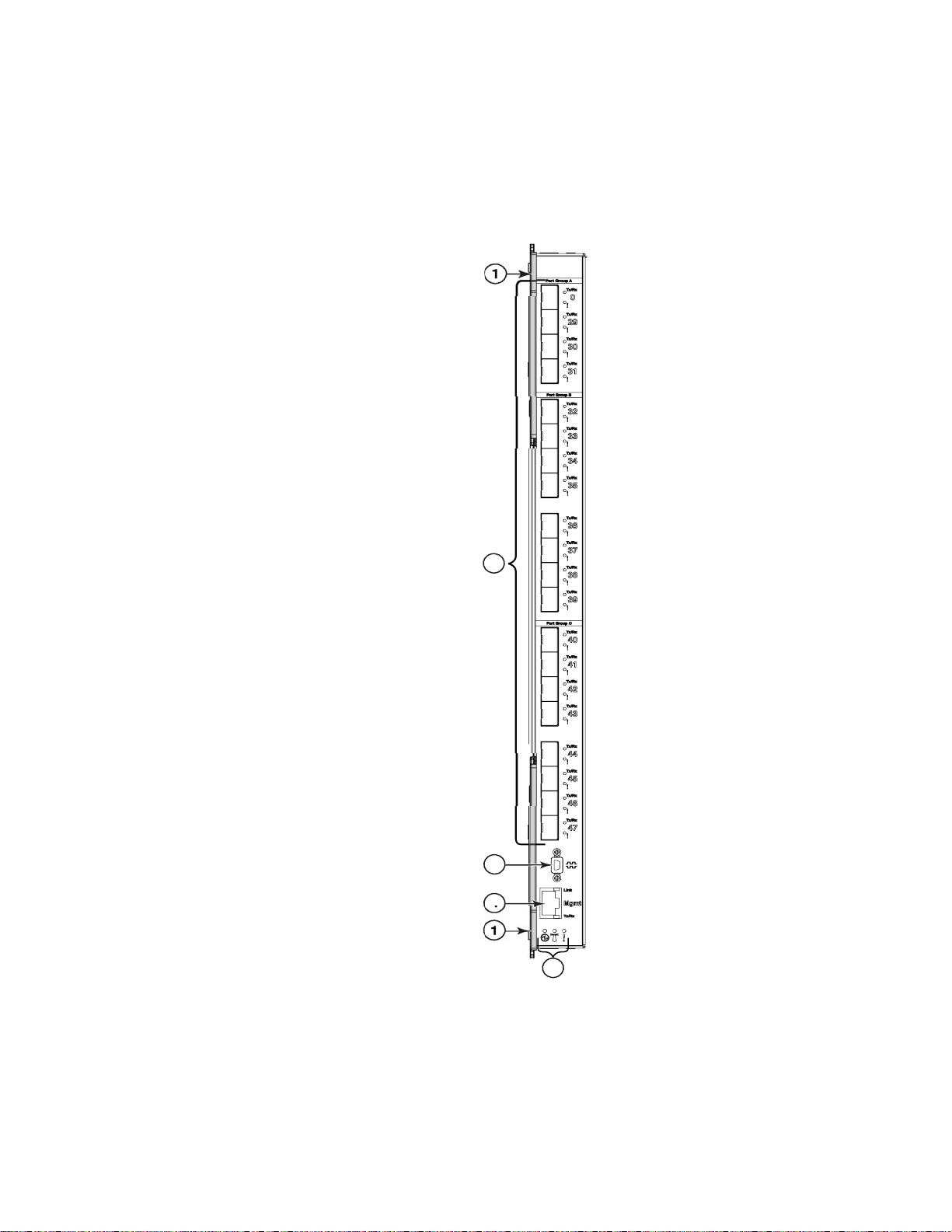
Locating the information panel, LEDs, and external ports
Figure 9 shows the IBM Flex System FC5022 16Gb SAN Scalable Switch information panel.
1 Trunk Group A (shown as ports 0 and 29–31) 7 Link LED
2 Trunk Group B (shown as ports 32–39) 8 System Status LED: Power
3 Trunk Group C (shown as ports 40–47) 9 System Status LED: Locator
4 Mini-USB console port 10 System Status LED: Fault
5 Tx/Rx LED 11 Fault (!) LED (One LED per port)
6 RJ-45 Ethernet port (Mgmt) 12 Tx/Rx LED (One LED per port)
FIGURE 9 Switch information panel
The illustrations in this document might differ slightly from your actual hardware.
22 IBM Flex System FC5022 16Gb SAN Scalable Switch User’s Guide
Page 37

Locating the information panel, LEDs, and external ports
NOTE
The information panel includes one mini-USB console port connector that is used for switch
management. This port requires a mini-USB plug on a serial cable. A single Ethernet port is also
provided that allows you to connect to the network using an RJ-45 connector.
The information panel offers 20 Fibre Channel (FC) ports that can be converted to fiber-optic
capability by use of SFP+ transceivers. Only Brocade-branded SFP+ transceivers are supported.
The information panel provides status information for the switch that is indicated by LED activity.
LEDs identify fault and activity information for each external port, switch status, and network
connectivity.
2
Information LEDs
The information panel on the switch supports three sets of LEDs that provide status information of
the switch, the network connection, and status of the external connections to the switch:
• The power, location, and status/fault LEDs on the bottom of the switch indicate the switch
status.
• The fault (!) and activity (Tx/Rx) LEDs on each FC port indicate the status of the external ports.
• The Ethernet port has separate link and activity LEDs.
In addition to the LEDs, the information panel is divided into three different groups (Group A, Group
B, and Group C). These groups support the ability to group “trunk ports.” A trunk port is a set of
individual ports that are grouped collectively to simulate a single port with a much faster data
transmission. The ability to group trunk ports must be done using a particular set of ports. The
group divisions help you determine which ports are recognized in a single trunk.
During normal operation, the green Power LED is lit and the amber Fault LED is off. An amber LED
on the chassis is lit when a system error or event has occurred. To identify the error or event, check
the IBM Chassis Management Module (CMM) event log or the switch system log.
An LED test occurs whenever the switch is turned on. All LEDs are lit and remain lit during POST,
after which, all LEDs except the OK LED turn off. Any errors that are detected during POST are
written to the system log.
When POST errors are written to the system log, these errors are also written to the CMM event log.
If a hardware error, such as a current fault occurs, the CMM displays it. If a software error occurs,
the CMM displays that the POST message was not completed and a POST error code indicates the
test that was running when the error was detected.
For more information on POST errors, see “POST errors” on page 41.
You can also use the CMM to ensure that the switch is operating correctly. For more information, see
the documentation for the chassis.
For more information, refer to the following sections:
• “Information panel Ethernet port LEDs” on page 24
• “Information panel Fibre Channel ports LEDs” on page 24
• “Ethernet port status LEDs” on page 24
• “System status LEDs” on page 25
Introduction 23
Page 38

Locating the information panel, LEDs, and external ports
NOTE
2
Information panel Ethernet port LEDs
The information panel Ethernet RJ-45 connector has two LEDs: the green LED on the top indicates
activity (Link); the green LED on the bottom indicates link speed (Tx/Rx).
Do not attach any devices to the RJ-45 connector other than a compatible cable.
Information panel Fibre Channel ports LEDs
The information panel displays 20 external Fibre Channel ports. Each port displays two LEDs that
indicate port status for a specific port:
• The upper LED shows the activity (Tx/Rx) status. When lit, it appears green.
• The lower LED shows the fault (!) status. When lit, it appears amber.
Tab le 6 identifies the port status information.
TABLE 6 Port status LEDs
Tx/Rx (Green) LED ! (Amber) LED Port Status
Off Off Offline
Steady green Off Online
Off Steady amber Out of sync
Off Slow flashing amber Disabled
Off Fast flashing amber Faulted
Flickering green Off Active
Slow flashing Slow flashing Beaconing
Slow flashing green Off Online, Segmented
Fast flashing green off Online, Internal Loopback
Ethernet port status LEDs
The Ethernet port status LED identifies link status and speed. When a link is established, the LED
appears as a flashing or steady green light.
Tab le 7 identifies the Ethernet port status LEDs and their descriptions.
TABLE 7 Ethernet port status LEDs
Status LED Description
Ethernet Link LED (green) No light. There is no link.
Steady green. There is a link.
Flashing green. There is link activity.
Ethernet Speed LED (green) No light. Port speed is 10 Mbps.
Steady green. Port speed is 100/1000 Mbps.
24 IBM Flex System FC5022 16Gb SAN Scalable Switch User’s Guide
Page 39

Locating the information panel, LEDs, and external ports
2
System status LEDs
Three system LEDs are located at the bottom of the front panel that identify system status. During
POST, the switch performs internal tests and LED tests. During POST, the LEDs are lit intermittently.
After POST is successfully completed, the LEDs will behave as described in
Tab le 8 identifies the three system LEDs. After POST is successfully completed, this is normal LED
behavior.
TABLE 8 System status LEDs
LED icon LED name LED description
The left-most LED is the Power LED. When lit, it appears green.
The middle LED is the Location LED. When lit, it appears blue.
! The right-most LED is the Fault LED. When lit, it appears amber.
Tab le 9 identifies how the system status LEDs behave when certain conditions are met. During
POST, all LEDs are lit briefly. Certain error conditions will illuminate the amber Fault LED; for
example, if temperatures exceed normal parameters. In such circumstances, power will shut off.
Tab le 8 and Tab le 9.
TABLE 9 System status LEDs functionality
Condition Power LED (Green) Location LED (Blue) Fault LED (Amber) Comments
Pre POST Off Off Off Power domain 2 off
POST start First 1-3 seconds on,
then blinking during
diagnostics and
initialization
POST critical failure Off Off On Switch nonfunctional; replacement
POST complete OK On Off Off Fully operational
Extended POST critical
failure
Operational critical fault Off Off On Switch nonfunctional; replacement
Switch FRU identify On On Off FRU ID operation from CMM
Off Off On Switch nonfunctional; replacement
First 1-3 seconds on,
then off
First 1-3 seconds on,
then off
Lamp test progress indication
required
required
required.
Introduction 25
Page 40

Configuring the switch
2
Configuring the switch
Configuring the switch requires that you first assign an IP address to the switch, which must be
done from the CMM using CLI. After the IP address is assigned, you then connect to the switch
(over SSH or using Web Tools) to define configuration settings. Log in to the switch using the
following default username and password settings:
User ID: USERID
Password: PASSW0RD (wherein the sixth character is a zero)
Configuring an IP address on the switch
1. Install the IBM Flex System FC5022 16Gb SAN Scalable Switch in the appropriate bay of the
IBM Flex System chassis. For more information, see “Installing the switch” on page 13.
2. (Optional) Connect the serial console to the mini-USB port on the switch information panel and
connect a terminal or terminal emulator.
3. Use secure Telnet (SSH) to the IBM Flex System Chassis Management Module (CMM)
IP address as described in the IBM Flex System Chassis Management Module User’s Guide.
4. Enter env
system> env –T system:switch[4]
5. From the CMM, enter ifconfig to display the current IP address.
–T system:switch[x], where x is the bay of the chassis in which the switch is installed.
6. To configure a static IP address, from the CMM, enter ifconfig –c static <IP Address>
-s <subnet mask> -g <Gateway IP Address>.
ifconfig -c static -i 10.20.21.207 -s 255.255.240.0 -g 10.20.16.1
26 IBM Flex System FC5022 16Gb SAN Scalable Switch User’s Guide
Page 41

Configuring the switch
NOTE
If you connected the serial console to the mini-USB port (as described in Step 2), on the switch
serial console, you can see the newly configured IP address on the switch.
7. From the CMM, enter ifconfig to confirm that the new IP address has been applied.
2
8. Use secure Telnet (SSH) to open a Telnet session to the switch using the newly configured
IP address. Log in using the following default username and password settings:
User ID: USERID
Password: PASSW0RD (wherein the sixth character is a zero)
The passwords that are used to access the switch are case-sensitive. To increase system security,
change the password after you log in for the first time. For more information, refer to the Fabric OS
Administrator’s Guide.
Connecting to the switch over SSH
The switch supports a command-line interface (CLI) that you can use to configure and control the
switch over the network through the SSH program. You can use the CLI to perform many basic
network-management functions. In addition, you can configure the switch for management through
an SNMP-based network-management system. SNMP v1, v2, and v3 are supported.
If you know the IP address for the switch and you have an existing network connection, you can use
the SSH program from an external management station or the CMM to access and control the
switch. The management station and the switch must be on the same IP subnet. If you have to
obtain the IP address for the switch or establish a network connection, contact your system or
network administrator.
Introduction 27
Page 42

Configuring the switch
NOTE
NOTE
2
To connect to the switch over the SSH interface, complete the following steps.
1. Open an SSH connection to the switch and enter the IP address for the switch, then press
Enter.
2. Log in using the following default username and password settings:
User ID: USERID
Password: PASSW0RD (wherein the sixth character is a zero)
The passwords that are used to access the switch are case-sensitive. To increase system security,
change the password after you log in for the first time. For more information, see the Fabric OS
Administrator’s Guide.
Connecting to the switch using Web Tools
You can connect directly to the switch using Web Tools as an alternative to using the CMM. Web
Tools is a graphical user interface that you can use to configure the switch directly.
To use Web Tools, you must first obtain the required digital certificates for SSL support. Certificates
are required on all switches that are to be accessed through SSL. You must also install a certificate
in the Java plug-in on the management workstation, and you might need to add a certificate to your
Web browser.
For more information on configuring SSL, see the Fabric OS Administrator’s Guide.
1. On a computer in the same network as the switch, open a supported Web browser, such as
Internet Explorer.
2. Using SSL, enter the IP address of the switch in the address field, for example:
https:// 10.24.151.224
3. Log in to Web Tools using the following default username and password settings:
User ID: USERID
Password: PASSW0RD (wherein the sixth character is a zero)
You are now ready to define the configuration settings. For more information on using Web Tools,
see the Web Tools Administrator’s Guide.
The passwords that are used to access the switch are case-sensitive. To increase system security,
change the password after you log in for the first time. For more information, see the Fabric OS
Administrator’s Guide.
28 IBM Flex System FC5022 16Gb SAN Scalable Switch User’s Guide
Page 43

Initial configuration
NOTE
NOTE
2
Connecting to the switch using the serial console port
To connect to the switch using the serial console port, complete the following steps.
1. Connect to the serial console port using the mini-USB to DB-9 cable.
2. Using a terminal emulator program, open a session to the assigned COM port for your cable
connection using the following settings:
BAUD rate 9600
Data bits 8
Parity None
Stop bits 1
Flow control None
3. Log in to the CLI using the following default username and password settings:
User ID: USERID
Password: PASSW0RD (wherein the sixth character is a zero)
Connecting to the switch using the front panel Ethernet (RJ-45) port
The internal Ethernet management port that connects to the Chassis Management Module is the
primary port used for switch management and is enabled by default.
The front panel Ethernet (RJ-45) port is an alternative port that can be used to manage the I/O
module if the primary port is not available or not functional. Only one of these two Ethernet
management ports can be enabled at any given time; enabling the external front panel Ethernet
port will disable the internal management port. Any changes made to enable the RJ-45 interface
are temporary and require a root password.
The switch will default to using the internal management port with a switch reboot.
Refer to the Technical Service Bulletin (TSB) for additional instructions when connecting to the
switch using the front panel Ethernet (RJ-45) port. To access the TSB, go to the IBM Flex System
Information Center at:
Please contact your technical support representative if you need further assistance when enabling
the front panel Ethernet (RJ-45) port.
Initial configuration
http://publib.boulder.ibm.com/infocenter/flexsys/information/index.jsp.
The operating software on the switch contains default configuration files that are installed during
the software installation. These initial configuration settings are not in a separate configuration file,
but are components of the software. When you restore the CMM to factory defaults, the original
configuration is restored.
Introduction 29
Page 44

Logging in to the switch
2
Logging in to the switch
The switch supports user-based security that enables you to prevent unauthorized users from
accessing the switch or changing its settings. For more information regarding user-based access,
see the Fabric OS Administrator’s Guide.
To log in to the switch, complete the following steps:
1. At the prompt, enter your user ID, then press Enter.
2. Enter your password, then press Enter. The main menu opens.
After you log in to the switch, you must set the date and time. For more information, see “Setting
date and time”.
Setting date and time
The IBM Flex System FC5022 16Gb SAN Scalable Switch maintains the current date and time
inside a battery-backed real-time clock (RTC) circuit. Date and time are used for logging events.
Switch operation does not depend on the date and time; a switch with an incorrect date and time
value still functions properly. However, because the date and time are used for logging, error
detection, and troubleshooting, you should set them correctly.
Time zones
You can set the time zone for the switch by name. You can also set the country and city, or time
zone parameters.
If the time zone is not set with the new options, the switch retains the offset time zone settings. The
tsTimeZone command includes an option to revert to the prior time zone format. For more
information about the
You can set the time zone for a switch using the tsTimeZone command. The tsTimeZone command
allows you to perform the following tasks:
• Display all of the time zones supported in the firmware
• Set the time zone based on a country and city combination or based on a time zone ID, such as
PST
The time zone setting has the following characteristics:
• You can view the time zone settings. However, only those with administrative permissions can
set the time zones.
• The tsTimeZone setting automatically adjusts for Daylight Saving Time.
• Changing the time zone on a switch updates the local time zone setup and is reflected in local
time calculations.
• By default, all switches are in the Greenwich Mean Time (GMT) time zone (0,0). If all switches
in a fabric are in one time zone, it is possible for you to keep the time zone setup at the default
setting.
• System services that have already started reflect the time zone changes only after the next
reboot.
• Time zone settings persist across failover for high availability.
--old option, see the Fabric OS Command Reference.
30 IBM Flex System FC5022 16Gb SAN Scalable Switch User’s Guide
Page 45

Setting date and time
2
Local time synchronization
You can synchronize the local time of the principal or primary fabric configuration server (FCS)
switch to a maximum of eight external Network Time Protocol (NTP) servers. To keep the time in
your switch current, it is recommended that the principal or primary FCS switch has its time
synchronized with at least one external NTP server. The other switches in the fabric automatically
take their time from the principal or primary FCS switch.
All switches in the fabric maintain the current clock server value in nonvolatile memory. By default,
this value is the local clock server <LOCL> of the principal or primary FCS switch. Changes to the
clock server value on the principal or primary FCS switch are propagated to all switches in the
fabric.
When a new switch enters the fabric, the time server daemon of the principal or primary FCS switch
sends out the addresses of all existing clock servers and the time to the new switch. If a switch with
v5.3.0 or later has entered the fabric, it will be able to store the list and the active servers;
pre-5.3.0 Fabric OS switches will ignore the new list parameter in the payload and will update only
the active server address.
If the active NTP server configured is IPv6, then distributing the same information in the fabric will
not be possible to switches earlier than v5.3.0 because IPv6 is supported for Fabric OS version
5.3.0 and later. The default value LOCL will be distributed to pre-5.3.0 switches.
The tsClockServer command accepts multiple server addresses in IPv4, IPv6, or Domain Name
System (DNS) name formats. When multiple NTP server addresses are passed, tsClockServer sets
the first obtainable address as the active NTP server. The rest are stored as backup servers that
can take over if the active NTP server fails. The principal or primary FCS switch synchronizes its
time with the NTP server every 64 seconds.
Setting the date
1. Log in using the following default username and password settings:
User ID: USERID
Password: PASSW0RD (wherein the sixth character is a zero)
2. Enter the date command, using the following syntax (the double quotation marks are required):
date "mmddHHMMyy"
The following values are used in the syntax:
• mm is the month; valid values are 01 through 12.
• dd is the date; valid values are 01 through 31.
• HH is the hour; valid values are 00 through 23.
• MM is minutes; valid values are 00 through 59.
• yy is the year; valid values are 00 through 99 (values greater than 69 are interpreted as
1970 through 1999, and values less than 70 are interpreted as 2000 through 2069).
switch:admin> date
Fri Sep 29 17:01:48 UTC 2007
switch:admin> date "0927123007"
Thu Sep 27 12:30:00 UTC 2007
Introduction 31
Page 46

Setting date and time
2
Setting time zones
You must perform the procedure on all switches for which the time zone must be set. However, you
only need to set the time zone once on each switch, because the value is written to nonvolatile
memory.
Use one of the two following procedures to set the time zone. The first procedure requires you to
select the actual time zone and the second requires you to select the country location of the
switch.
The following procedure describes how to set the current time zone to Central Standard Time using
the timezone_fmt mode.
1. Log in to the switch using the default password, which is password.
2. Enter the tsTimeZone command as follows:
switch:admin> tstimezone [--interactive]/ [, timezone_fmt]
Use the timezone_fmt mode to set the time zone by Country/City or by time zone ID, such as
Pacific Standard Time (PST).
The following example shows how to change the time zone to US/Central.
switch:admin> tstimezone
Time Zone : US/Pacific
switch:admin> tstimezone US/Central
switch:admin> tstimezone
Time Zone : US/Central
The following procedure describes how to set the current time zone using interactive mode to
Pacific Standard Time.
1. Enter the tsTimeZone --interactive command as follows:
switch:admin> tstimezone --interactive
You are prompted to select a general location.
Please identify a location so that time zone rules can be set correctly.
2. Enter the appropriate number or press Ctrl-D to quit.
3. At the prompt, select a country location.
4. At the prompt, enter the appropriate number to specify the time zone region or press Ctrl-D to
quit.
Synchronizing local time using NTP
Complete the following steps to synchronize the local time using NTP.
1. Log in to the switch using the default password, which is password.
2. Enter the tsClockServer command:
switch:admin> tsclockserver "<ntp1;ntp2>"
32 IBM Flex System FC5022 16Gb SAN Scalable Switch User’s Guide
Page 47

In this syntax, ntp1 is the IP address or DNS name of the first NTP server, which the switch
must be able to access. Ntp2 is the name of the second NTP server and is optional. The entire
operand “<ntp1;ntp2>” is optional; by default, this value is LOCL, which uses the local clock of
the principal or primary switch as the clock server.
switch:admin> tsclockserver
LOCL
switch:admin> tsclockserver "132.163.135.131"
switch:admin> tsclockserver
132.163.135.131
The following example shows how to set up more than one NTP server using a DNS name:
switch:admin> tsclockserver "10.32.170.1;10.32.170.2;ntp.localdomain.net"
Updating Clock Server configuration...done.
Updated with the NTP servers
Changes to the clock server value on the principal or primary FCS switch are propagated to all
switches in the fabric.
Managing the switch
Managing the switch
2
SNMP v3 authentication
Two user roles are supported:
• snmpadmin—Provides read-write access
• snmpuser—Provides read-only access
Tab le 10 lists user login information. Each entry requires a separate password. The default
algorithm (MD5/SHA) is used to create the authentication keys.
TABLE 10 SNMP authentication and privacy protocols
User Authentication password Authentication protocol Privacy password Privacy protocol1Access type
snmpadmin2 admin2 MD5 admin2 AES Get/Set
snmpadmin3 admin3 SHA admin3 AES Get/Set
snmpuser1 user1 SHA user1 AES Get
snmpuser2 user2 SHA user2 AES Get
snmpuser3 user3 SHA user3 AES Get
1. AES = 128-bit encryption
For more information, refer to the snmpConfig commands supporting SNMPv3 configuration
parameters, as described in the Fabric OS Command Reference Manual.
Introduction 33
Page 48

Managing the switch
NOTE
2
Brocade Inter-Switch Link Trunking
Brocade Inter-Switch Link (ISL) Trunking is optional software that allows you to create trunking
groups of ISLs between adjacent switches. Up to eight FC ports on the switch can be used as a
trunking group to achieve speeds up to 128 Gbps (256 Gbps full duplex) for optimal bandwidth
utilization and load balancing. For more information about Brocade ISL Trunking, see the Fabric OS
Administrator’s Guide.
Fabric OS Native and Access Gateway modes
The switch can function in either Fabric OS Native mode or Access Gateway mode. The switch is
shipped in Fabric OS Native mode by default.
• You can enable Access Gateway mode using Fabric OS commands or Web Tools.
• All ports must be enabled on a switch for Access Gateway to be enabled, as all ports are
utilized under the port mapping.
• When you enable Access Gateway, you can use the default F_Port-to-N_Port mappings or
change this mapping using the CLI or Web Tools after you configure an IP address. Access
Gateway simplifies switch deployment by using NPIV. NPIV provides FC switch functions that
improve switch scalability, manageability, and interoperability. For more information on Access
Gateway, refer to the following references:
- For general information and details on using Access Gateway, refer to the Access Gateway
Administrator’s Guide Supporting Fabric OS v7.0.0.
- For specific instructions to prepare the edge fabric before connecting it to the Access
Gateway (since Access Gateway relies on NPIV technology for its connection to the edge
fabric), refer to the SAN TECH NOTE - Preparing to Install the Brocade Access Gateway.
- For a list of F_Ports mapped to N_Ports by default, refer to Table 11.
TABLE 11 F_port to N_port mappings
F port N port F port N port
1, 21 0 11 38
2, 22 29 12 39
3, 23 30 13 40
4, 24 31 14 41
5, 25 32 15 42
6, 26 33 16 43
7, 27 34 17 44
8, 28 35 18 45
9361946
10 37 20 47
Access Gateway can be connected directly into a storage array with at least one port connected
to an external SAN fabric.
34 IBM Flex System FC5022 16Gb SAN Scalable Switch User’s Guide
Page 49

Managing the switch
ATTENTION
2
• Fabric OS features available to the IBM Flex System FC5022 16Gb SAN Scalable Switch
depend on whether the switch is configured in Access Gateway or Fabric OS Native mode. For a
list of available features for each mode, refer to the Access Gateway Administrator’s Guide
Supporting Fabric OS v7.0.0.
• In Access Gateway mode, the external ports can be N_Ports, and the internal ports (1–28) can
be F_Ports.
To disable and enable Access Gateway mode, refer to the Access Gateway Administrator’s Guide
Supporting Fabric OS v7.0.0.
Backing up the configuration
Prior to backing up a switch configuration, you can check the switch configuration by initiating the
switchShow and fabricShow commands. The switchShow command displays switch and port
status; the fabricShow command displays fabric membership information.
Complete these steps to back up the switch configuration to an FTP server.
1. Open a Telnet or SSH session to the switch.
2. Enter configUpload, which uploads the switch configuration to the server, making it available
for downloading to a replacement switch, if necessary.
You are presented with a series of prompts.
3. Follow the prompts to upload the configuration.
It is recommended that you back up the configuration on a regular basis to ensure that a complete
configuration is available for downloading to a replacement switch.
For specific instructions about how to back up a configuration, refer to the Fabric OS
Administrator’s Guide. For detailed information about the commands used in backing up a
configuration, refer to the Fabric OS Command Reference Manual.
Resetting the switch to factory defaults
Restoring the switch to factory defaults is disruptive. Before doing so, make sure any program using
the switch has an alternate path to the storage, and save the switch configuration. If the switch is
connected to an existing SAN, disconnect the switch from the SAN before restoring to factory
defaults, then follow proper setup procedures before reconnecting.
Use the CMM to reset the switch to factory defaults.
1. Open the CMM and log in with admin privileges.
2. Select I/O Module Tasks > Configuration.
3. Select the bay where the switch is installed.
4. Select Advanced Configuration.
5. Click Restore Defaults.
Introduction 35
Page 50

Managing the switch
2
Removing or replacing the switch
1. Before removing a switch from the chassis, read the following safety information:
• “Safety” on page vii
• “System reliability guidelines” on page 11
2. Disconnect any cables from the switch that you are removing. For additional information about
disconnecting cables, see “Installing and removing an SFP+ transceiver” on page 16, and the
documentation that comes with the cables and optional network devices to which the cables
have been connected. For the locations of the connectors on the chassis, see the
documentation that comes with the chassis.
3. Pull the release latches out from the switch, as shown in Figure 3 on page 2-14. The switch
moves out of the bay approximately 0.6 cm (0.25 inch).
4. Slide the switch out of the bay and set it aside.
5. Replace the removed switch with either another switch or a filler panel. You must complete this
step within 60 seconds.
6. If you installed another switch in the bay, reconnect the cables that you disconnected in step 2.
Attach any additional cables that are required by the switch. For additional information about
connecting cables, see “Installing and removing an SFP+ transceiver” on page 16, and the
documentation that comes with the cables and optional network devices to which the cables
have been connected. For the locations of the connectors on the chassis, see the
documentation that comes with the chassis.
7. Install SFP+ transceivers and dust caps where appropriate. For safety information and
instructions, see the following sections:
• “Installing and removing an SFP+ transceiver” on page 16
• “Using dust caps” on page 19
8. Establish a connection to the CMM. For more information, see the following sections:
• “Connecting to the switch over SSH” on page 27.
• “Connecting to the switch using Web Tools” on page 28
36 IBM Flex System FC5022 16Gb SAN Scalable Switch User’s Guide
Page 51

Chapter
NOTE
Updating the Firmware
This chapter contains information and instructions for updating the IBM Flex System FC5022 16Gb
SAN Scalable Switch firmware.
The switch might support features that are not described in the documentation that comes with the
switch, and the documentation might be updated occasionally to include information about those
features or technical updates.
To determine if firmware and documentation updates are available, go to:
http://ibm.brocadeassist.com/public/FabricOSv7xRelease
Determining the switch firmware level
After you install the switch in the chassis, make sure the latest firmware is installed on the switch.
You can access firmware information using multiple methods: through the CMM, from the switch
using the CLI, and using Web Tools.
3
Determining firmware from the CMM
1. Log in to the CMM as described in the IBM Flex System Chassis Management Module User’s
Guide. If necessary, obtain the IP address of the CMM from your system administrator. The
login window opens.
2. From the Monitors menu, click Firmware VPD. The Firmware VPD window opens.
3. In the I/O Module Firmware VPD area, locate the chassis bay containing the switch you
installed; then, note the corresponding level of the firmware for the switch displayed under the
Revision column.
Determining firmware from the switch using the CLI
1. Connect to the switch.
2. Log in as “admin.” Use the following default username and password settings:
User ID: USERID
Password: PASSW0RD (wherein the sixth character is a zero)
3. Enter the firmwareShow command to check the current firmware version on the switch.
©Copyright IBM Corp. 2012 37
Page 52

Determining the switch firmware level
NOTE
NOTE
3
Determining firmware using Web Tools
Before you install Web Tools on your workstation, verify that your switch and workstation meet the
Web Tools requirements. Web Tools requires any browser that conforms to HTML version 4.0,
JavaScript version 1.0, and Java Plug-in 1.6.0_29 or later.
You must connect to Web Tools using SSL. To do this, you will require a digital certificate from an
Internet Certificate Authority (CA). For more information on certificates, see the Fabric OS
Administrator’s Guide.
Make sure you have Java plug-in Version 6 Update 29 (build 1.6.0_29-b11) or later installed on your
management workstation.
For supported browser and platform information, see the Web Tools Administrator’s Guide.
1. On a computer in the same network as the switch, open a supported Web browser.
2. Enter the IP address of the switch in the address field, for example:
https://10.24.151.224
3. Press Enter.
4. Log in to Web Tools using the following default username and password settings:
User ID: USERID
Password: PASSW0RD (wherein the sixth character is a zero)
5. Select Switch Admin, then click the Firmware Download tab to display current firmware
information.
The passwords that are used to access the switch are case-sensitive. To increase system security,
change the password after you log in for the first time. For more information, see the Fabric OS
Administrator’s Guide.
38 IBM Flex System FC5022 16Gb SAN Scalable Switch User’s Guide
Page 53

Upgrading the switch firmware
ATTENTION
After you locate the correct firmware to download to the IBM Flex System FC5022 16Gb SAN
Scalable Switch, you can use either the CLI or Web Tools to perform the download.
The firmware download for the switch is disruptive. Make sure no traffic is flowing through the switch
during the download process.
For specifics on how to perform the firmware download, refer to the following:
• If you are using CLI to perform the download, refer to the chapter, “Installing and Maintaining
Firmware,” in the Fabric OS Administrator’s Guide.
• If you are using Web Tools to perform the download, refer to the chapter, “Maintaining
Configurations and Firmware,” in the Web Tools Administrator’s Guide.
Upgrading the switch firmware
3
Updating the Firmware 39
Page 54

Upgrading the switch firmware
3
40 IBM Flex System FC5022 16Gb SAN Scalable Switch User’s Guide
Page 55

Chapter
Chapter 4. Solving Problems
This chapter provides troubleshooting information to help you solve problems that might occur
while you are setting up the IBM Flex System FC5022 16Gb SAN Scalable Switch.
If you cannot locate and correct a problem by using the information in this section, see
Appendix A“Getting Help and Technical Assistance”.
Running POST
The switch processes a series of tests during power-up or a restart (power-on self-test, or POST) to
ensure that it is fully operational. These tests take approximately one minute to complete. The
CMM reads the test results and displays them for you. During normal operation, these tests are
completed without error, and the green OK LED is lit. However, if the switch fails POST, the amber
error LED on the switch and the system-error LED on the chassis are lit. An event is stored in the
event log in the system status panel of the CMM. The specific failure is displayed on the system
status I/O panel of the CMM.
For the locations and descriptions of the switch LEDs, see “Locating the information panel, LEDs,
and external ports” on page 22.
4
POST errors
Two types of errors can result: noncritical and critical. A noncritical error applies to one port, and
the switch is operational. You can continue to operate the switch; however, you must replace it as
soon as possible. When critical errors occur, the switch does not operate. To view POST results,
complete the following steps:
1. Log in to the CMM as described in the IBM Flex System Chassis Management Module
Command-Line Interface Reference Guide. If necessary, obtain the IP address of the CMM
from your system administrator. The login window opens.
2. Turn off the power to the switch; then, turn it on again.
3. After POST is completed, the CMM displays the results. Refresh the window to view the POST
results. If a critical error occurs, replace the switch. If a noncritical error occurs, see the switch
error log for additional details.
Tab le 12 describes the basic critical and noncritical failures. This abbreviated list is representative;
it is not an exhaustive list. An error code is associated with each failure. Error codes are displayed
on the CMM Switch Information window. Be sure to note the applicable error code and
corresponding failure. You might have to provide this information when you call for service. For
details, see
Appendix A“Getting Help and Technical Assistance”.
©Copyright IBM Corp. 2012 41
Page 56

Parts listing
4
Parts listing
TABLE 12 Error listing
Diagnostic indicator (in hex) Failing functional area Failure criticality
00 - 7F Base internal functions Critical
80 - 9F Internal interface failures Noncritical
A0 - AF External interface errors Noncritical
B0 - FE Reserved Noncritical
FF Switch “good” indicator Operation
Replaceable components are of three types:
• Tier 1 customer replaceable unit (CRU): Replacement of Tier 1 CRUs is your
responsibility. If IBM installs a Tier 1 CRU at your request, you will be charged
for the installation.
• Tier 2 customer replaceable unit (CRU): You may install a Tier 2 CRU
yourself or request IBM to install it, at no additional charge, under the type of
warranty service that is designated for your server.
• Field replaceable unit (FRU): FRUs must only be installed by trained service
technicians.
For information about the terms of the warranty, see the Warranty Information
document.
The replaceable components in Tab le 13 are Tier 1 CRUs. If other
components require replacement, see the documentation that comes with those
devices for instructions.
TABLE 13 Parts listing
Part CRU number (Tier 1)
IBM Flex System FC5022 16Gb
SAN Scalable Switch
69Y1911
42 IBM Flex System FC5022 16Gb SAN Scalable Switch User’s Guide
Page 57

Appendix
Getting Help and Technical Assistance
If you need help, service, or technical assistance, or just want more information about IBM
products, you will find a wide variety of sources available from IBM to assist you. This section
contains information about where to go for additional information about IBM and IBM products,
what to do if you experience a problem with your system, and whom to call for service, if it is
necessary.
Before you call
Before you call, make sure you have taken these steps to try to solve the problem yourself:
• Check all cables to make sure that they are connected.
• Check the power switches to make sure that the system and any optional
devices are turned on.
• Use the troubleshooting information in your system documentation, and use the
diagnostic tools that come with your system.
• Go to the IBM support Web site at http://www.ibm.com/supportportal/ to check
for technical information, hints, tips, and new device drivers or to submit a
request for information.
You can solve many problems without outside assistance by following the
troubleshooting procedures that IBM provides in the online help or in the
documentation that is provided with your IBM product. The documentation that
comes with IBM systems also describes the diagnostic tests that you can perform.
Most systems, operating systems, and programs come with documentation that
contains troubleshooting procedures and explanations of error messages and error
codes. If you suspect a software problem, see the documentation for the operating
system or program.
A
Using the documentation
Information about your IBM system and preinstalled software, if any, or optional
device is available in the documentation that comes with the product. That
documentation can include printed documents, online documents, readme files,
and help files. See the troubleshooting information in your system documentation
for instructions for using the diagnostic programs. The troubleshooting information
or the diagnostic programs might tell you that you need additional or updated
device drivers or other software. IBM maintains pages on the World Wide Web
where you can get the latest technical information and download device drivers
and updates. To access these pages, go to http://www.ibm.com/supportportal/
and follow the instructions.
©Copyright IBM Corp. 2012 43
Page 58

Getting help and information from the World Wide Web
A
Getting help and information from the World Wide Web
On the World Wide Web, the IBM Web site has up-to-date information about IBM
systems, optional devices, services, and support. You can find service information
for IBM systems and optional devices at http://www.ibm.com/supportportal/.
Software service and support
Through IBM Support Line, you can get telephone assistance, for a fee, with usage,
configuration, and software problems. For information about which products are
supported by Support Line in your country or region, see http://www.ibm.com/
services/supline/products/.
For more information about Support Line and other IBM services, see
http://www.ibm.com/services/, or see http://www.ibm.com/planetwide/ for
support telephone numbers. In the U.S. and Canada, call 1-800-IBM-SERV
(1-800-426-7378).
Hardware service and support
You can receive hardware service through your IBM reseller or IBM Services. To
locate a reseller authorized by IBM to provide warranty service, go to
http://www.ibm.com/partnerworld/ and click Find a Business Partner on the
right side of the page. For IBM support telephone numbers, see
http://www.ibm.com/planetwide/. In the U.S. and Canada, call 1-800-IBM-SERV
(1-800-426-7378).
In the U.S. and Canada, hardware service and support is available 24 hours a day,
7 days a week. In the U.K., these services are available Monday through Friday,
from 9 a.m. to 6 p.m.
IBM Taiwan product service
IBM Taiwan product service contact information:
IBM Taiwan Corporation
3F, No 7, Song Ren Rd.
Taipei, Taiwan
Telephone: 0800-016-888
44 IBM Flex System FC5022 16Gb SAN Scalable Switch User’s Guide
Page 59

Appendix
Notices
This information was developed for products and services offered in the U.S.A.
IBM may not offer the products, services, or features discussed in this document in
other countries. Consult your local IBM representative for information on the
products and services currently available in your area. Any reference to an IBM
product, program, or service is not intended to state or imply that only that IBM
product, program, or service may be used. Any functionally equivalent product,
program, or service that does not infringe any IBM intellectual property right may
be used instead. However, it is the user’s responsibility to evaluate and verify the
operation of any non-IBM product, program, or service.
IBM may have patents or pending patent applications covering subject matter
described in this document. The furnishing of this document does not give you
any license to these patents. You can send license inquiries, in writing, to:
IBM Director of Licensing
IBM Corporation
North Castle Drive
Armonk, NY 10504-1785
U.S.A.
B
INTERNATIONAL BUSINESS MACHINES CORPORATION PROVIDES THIS
PUBLICATION “AS IS” WITHOUT WARRANTY OF ANY KIND, EITHER
EXPRESS OR IMPLIED, INCLUDING, BUT NOT LIMITED TO, THE IMPLIED
WARRANTIES OF NON-INFRINGEMENT, MERCHANTABILITY OR FITNESS
FOR A PARTICULAR PURPOSE. Some states do not allow disclaimer of express or
implied warranties in certain transactions, therefore, this statement may not apply
to you.
This information could include technical inaccuracies or typographical errors.
Changes are periodically made to the information herein; these changes will be
incorporated in new editions of the publication. IBM may make improvements
and/or changes in the product(s) and/or the program(s) described in this
publication at any time without notice.
Any references in this information to non-IBM websites are provided for
convenience only and do not in any manner serve as an endorsement of those
websites. The materials at those websites are not part of the materials for this IBM
product, and use of those websites is at your own risk.
IBM may use or distribute any of the information you supply in any way it
believes appropriate without incurring any obligation to you.
©Copyright IBM Corp. 2012 45
Page 60

Trademarks
IBM, the IBM logo, and ibm.com are trademarks of International
Business Machines Corp., registered in many jurisdictions worldwide.
Other product and service names might be trademarks of IBM or other
companies. A current list of IBM trademarks is available on the web at
"Copyright and trademark information"
at http://www.ibm.com/legal/copytrade.shtml
Adobe and PostScript are either registered trademarks or trademarks of
Adobe Systems Incorporated in the United States and/or other countries.
Cell Broadband Engine is a trademark of Sony Computer Entertainment, Inc., in the
United States, other countries, or both and is used under license
therefrom.
Intel, Intel Xeon, Itanium, and Pentium are trademarks
or registered trademarks of Intel Corporation or its subsidiaries
in the United States and other countries.
Java and all Java-based trademarks and logos are trademarks or registered
trademarks of Oracle and/or its affiliates.
Linux is a registered trademark of Linus
Torvalds in the United States, other countries, or both.
Microsoft, Windows, and Windows NT are trademarks of Microsoft Corporation in
the United States, other countries, or both.
UNIX is a registered trademark of The Open Group in the United States and other countries.
B
Trademarks
46 IBM Flex System FC5022 16Gb SAN Scalable Switch User’s Guide
Page 61

Important notes
This product is not intended to be connected directly or indirectly by any means
whatsoever to interfaces of public telecommunications networks, nor is it intended
to be used in a public services network.
Important notes
B
Documentation format
The publications for this product are in Adobe Portable Document Format (PDF)
and should be compliant with accessibility standards. If you experience difficulties
when you use the PDF files and want to request a web-based format or accessible
PDF document for a publication, direct your mail to the following address:
Information Development
IBM Corporation
205/A015
3039 E. Cornwallis Road
P.O. Box 12195
Research Triangle Park, North Carolina 27709-2195
U.S.A.
In the request, be sure to include the publication part number and title.
When you send information to IBM, you grant IBM a nonexclusive right to use or
distribute the information in any way it believes appropriate without incurring any
obligation to you.
Notices 47
Page 62

Electronic emission notices
B
Electronic emission notices
Federal Communications Commission (FCC) statement
Note: This equipment has been tested and found to comply with the limits for a
Class A digital device, pursuant to Part 15 of the FCC Rules. These limits are
designed to provide reasonable protection against harmful interference when the
equipment is operated in a commercial environment. This equipment generates,
uses, and can radiate radio frequency energy and, if not installed and used in
accordance with the instruction manual, may cause harmful interference to radio
communications. Operation of this equipment in a residential area is likely to cause
harmful interference, in which case the user will be required to correct the
interference at his own expense.
Properly shielded and grounded cables and connectors must be used in order to
meet FCC emission limits. IBM is not responsible for any radio or television
interference caused by using other than recommended cables and connectors or by
unauthorized changes or modifications to this equipment. Unauthorized changes
or modifications could void the user’s authority to operate the equipment.
This device complies with Part 15 of the FCC Rules. Operation is subject to the
following two conditions: (1) this device may not cause harmful interference, and
(2) this device must accept any interference received, including interference that
may cause undesired operation.
Industry Canada Class A emission compliance statement
This Class A digital apparatus complies with Canadian ICES-003.
Avis de conformité à la réglementation d’Industrie Canada
Cet appareil numérique de la classe A est conforme à la norme NMB-003 du
Canada.
Australia and New Zealand Class A statement
Attention: This is a Class A product. In a domestic environment this product may cause radio
interference in which case the user may be required to take adequate measures.
European Union EMC Directive conformance statement
This product is in conformity with the protection requirements of EU Council Directive
2004/108/EC on the approximation of the laws of the Member States relating to
electromagnetic compatibility. IBM cannot accept responsibility for any failure to satisfy the
protection requirements resulting from a nonrecommended modification of the product,
including the fitting of non-IBM option cards.
Attention: This is an EN 55022 Class A product. In a domestic environment this product may
cause radio interference in which case the user may be required to take adequate measures.
48 IBM Flex System FC5022 16Gb SAN Scalable Switch User’s Guide
Page 63

Electronic emission notices
Responsible manufacturer:
International Business Machines Corp.
New Orchard Rd.
Armonk, NY, 10504
914-499-1900
European Community contact:
IBM Technical Regulations, Department 456
IBM-Allee 1, 71137 Ehningen, Germany
Telephone: +49 7032 15-2937
E-mail: tjahn@de.ibm.com
Germany Class A statement
Deutschsprachiger EU Hinweis:
Hinweis für Geräte der Klasse A EU-Richtlinie zur Elektromagnetischen
Verträglichkeit
Dieses Produkt entspricht den Schutzanforderungen der EU-Richtlinie
2004/108/EG zur Angleichung der Rechtsvorschriften über die elektromagnetische
Verträglichkeit in den EU-Mitgliedsstaaten und hält die Grenzwerte der EN 55022
Klasse A ein.
B
Um dieses sicherzustellen, sind die Geräte wie in den Handbüchern beschrieben zu
installieren und zu betreiben. Des Weiteren dürfen auch nur von der IBM
empfohlene Kabel angeschlossen werden. IBM übernimmt keine Verantwortung für
die Einhaltung der Schutzanforderungen, wenn das Produkt ohne Zustimmung der
IBM verändert bzw. wenn Erweiterungskomponenten von Fremdherstellern ohne
Empfehlung der IBM gesteckt/eingebaut werden.
EN 55022 Klasse A Geräte müssen mit folgendem Warnhinweis versehen werden:
“Warnung: Dieses ist eine Einrichtung der Klasse A. Diese Einrichtung kann im
Wohnbereich Funk-Störungen verursachen; in diesem Fall kann vom Betreiber
verlangt werden, angemessene Maßnahmen zu ergreifen und dafür
aufzukommen.”
Deutschland: Einhaltung des Gesetzes über die
elektromagnetische Verträglichkeit von Geräten
Dieses Produkt entspricht dem “Gesetz über die elektromagnetische Verträglichkeit
von Geräten (EMVG)”. Dies ist die Umsetzung der EU-Richtlinie 2004/108/EG in
der Bundesrepublik Deutschland.
Zulassungsbescheinigung laut dem Deutschen Gesetz über die
elektromagnetische Verträglichkeit von Geräten (EMVG) (bzw. der
EMC EG Richtlinie 2004/108/EG) für Geräte der Klasse A
Dieses Gerät ist berechtigt, in Übereinstimmung mit dem Deutschen EMVG das
EG-Konformitätszeichen - CE - zu führen.
Verantwortlich für die Einhaltung der EMVG Vorschriften ist der Hersteller;
International Business Machines Corp.
New Orchard Rd.
Armonk, NY, 10504
914-499-1900
Notices 49
Page 64

Electronic emission notices
B
De verantwortliche Ansprechpartner des Herstellers in der EU ist:
IBM Deutschland
IBM Technical Regulations, Department 456
IBM-Allee 1, 71137 Ehningen, Germany
Telephone: +49 7032 15-2937
E-mail: tjahn@de.ibm.com
Generelle Informationen:
Das Gerät erfüllt die Schutzanforderungen nach EN 55024 und EN 55022 Klasse A.
Japan VCCI Class A statement
This is a Class A product based on the standard of the Voluntary Control Council
for Interference (VCCI). If this equipment is used in a domestic environment, radio
interference may occur, in which case the user may be required to take corrective
actions.
50 IBM Flex System FC5022 16Gb SAN Scalable Switch User’s Guide
Page 65

Electronic emission notices
This is electromagnetic wave compatibility equipment
for business (Type A). Sellers and users need to pay
attention to it. This is for any areas other than home.
B
Notices 51
Page 66

Electronic emission notices
B
52 IBM Flex System FC5022 16Gb SAN Scalable Switch User’s Guide
Page 67

Index
A
additional documentation, 1, 2
B
boot flash, 6
Brocade documentation
, 2
C
command line interface (CLI), 26
compact flash
configuration
backing up, 33
initial, 28
resetting, 33
via Web Tools, 27
critical errors, 39
, 6
Federal Communications Commission (FCC)
statement
Germany Electromagnetic Compatibility Directive, 57
Industry Canada Class A emission compliance
statement
Japanese VCCI Class A statement, 58
error codes, 39
errors, critical and noncritical
ESB, 5
Ethernet cabing, 21
Ethernet port
external, 29
internal, 29
, 56
, 56
, 39
F
firmware
determining level, 35
downloading, 37
upgrading, 35
flash, 6
FTP server
, 33
D
date and time, setting, 28
dimensions
documentation
additional, 1, 2
, 6
E
Electronic emission notices
Australia and New Zealand Class A statement, 56
Avis de conformité à la réglementation d’Industrie
Canada
European Union EMC Directive conformance
statement
©Copyright IBM Corp. 2012 53
, 56
, 56
G
getting help, 41
hardware support, 42
IBM documentation, 41
software support, 42
World Wide Web, 42
guidelines
installation, 11
reliability, 11
static-sensitive devices, 12
H
handling
SFP+ transceivers, 16
static-sensitive devices, 12
Page 68

hardware support, 42
HSSM bays, identifying
I
I/O Module Tasks, 33
IBM documentation
installation guidelines
, 1
K
, 13
, 11
P
parts listing, 40
POST
, 39
errors, 39
processor, 6
R
reliability guidelines, 11
kernel, 6
L
LEDs
information, 22
M
memory, 6
mini-USB console port
N
noncritical errors, 39
notices
, 53
O
, 20
S
safety statements, ix
setting date and time
software support
SSH
, 33
SSH access
main menu, 27
static-sensitive devices, handling, 12
switch
reset and restart, 37
switch components, 8
switch module
physical dimensions, 6
weight, 6
, 26
, 28
, 42
T
Taiwan support, 42
technical help
Telnet
, 33
, 41
optical cabling, 16
U
upgrading firmware, 35
USB cable
connecting, 20
W
Web Tools, 27
weight, switch module
54 IBM Flex System FC5022 16Gb SAN Scalable Switch User’s Guide
, 6
Page 69

Page 70

Part Number: 88Y7924
Printed in USA
(IP) P/N: 88Y7924
*88Y7924*
 Loading...