

Page 1

IBM TotalStorage FAStT600
Fibre Channel Storage Server
Installation and User’s Guide
GC26-7531-01
Page 2

Page 3

IBM TotalStorage FAStT600
Fibre Channel Storage Server
Installation and User’s Guide
GC26-7531-01
Page 4

Note: Before using this information and the product it supports, be sure to read the general information in “Notices” on page 79.
Second Edition (June 2003)
© Copyright International Business Machines Corporation 2003. All rights reserved.
US Government Users Restricted Rights – Use, duplication or disclosure restricted by GSA ADP Schedule Contract
with IBM Corp.
Page 5

Safety
Before installing this product, read the Safety information.
Antes de instalar este produto, leia as Informações de Segurança.
Pred instalací tohoto produktu si prectete prírucku bezpecnostních instrukcí.
Læs sikkerhedsforskrifterne, før du installerer dette produkt.
Lees voordat u dit product installeert eerst de veiligheidsvoorschriften.
Ennen kuin asennat tämän tuotteen, lue turvaohjeet kohdasta Safety Information.
Avant d’installer ce produit, lisez les consignes de sécurité.
Vor der Installation dieses Produkts die Sicherheitshinweise lesen.
Prima di installare questo prodotto, leggere le Informazioni sulla Sicurezza.
Les sikkerhetsinformasjonen (Safety Information) før du installerer dette produktet.
Antes de instalar este produto, leia as Informações sobre Segurança.
© Copyright IBM Corp. 2003 iii
Page 6

Antes de instalar este producto, lea la información de seguridad.
Läs säkerhetsinformationen innan du installerar den här produkten.
The following Caution notices are printed in English throughout this document. For
translations of these notices, refer to IBM Safety Information.
Statement 3
CAUTION:
When laser products (such as CD-ROMs, DVD drives, fiber optic devices, or
transmitters) are installed, note the following:
v Do not remove the covers. Removing the covers of the laser product could result in
exposure to hazardous laser radiation. There are no serviceable parts inside the
device.
v Use of controls or adjustments or performance of procedures other than those
specified herein might result in hazardous radiation exposure.
Danger
Some laser products contain an embedded Class 3A or Class 3B laser diode. Note the
following.
Laser radiation when open. Do not stare into the beam, do not view directly with optical
instruments, and avoid direct exposure to the beam.
Class 1 laser statement
Class 1 Laser Product
Laser Klasse 1
Laser Klass 1
Luokan 1 Laserlaite
Appareil A Laser de Classe 1
`
IEC 825-1:1993 CENELEC EN 60 825
Statement 4
≥18 kg (37 lbs) ≥32 kg (70.5 lbs) ≥55 kg (121.2 lbs)
iv IBM TotalStorage FAStT600 Fibre Channel Storage Server: Installation and User’s Guide
Page 7
Statement 4
CAUTION:
Use safe practices when lifting.
Statement 5
CAUTION:
The power control button on the device and the power supply do not turn off the
electrical current supplied to the device. The device also might have more than one
power cord. To remove all electrical current from the device, ensure that all power
cords are disconnected from the power source.
2
1
Statement 8:
CAUTION:
Never remove the cover on a power supply or any part that has the following
label attached.
Hazardous voltage, current, and energy levels are present inside any
component that has this label attached. There are no serviceable parts inside
these components. If you suspect a problem with one of these parts, contact
a service technician.
Safety v
Page 8

vi IBM TotalStorage FAStT600 Fibre Channel Storage Server: Installation and User’s Guide
Page 9

Contents
||
Safety ............................iii
Figures ............................xi
Tables............................xiii
About this document ......................xv
Who should read this document ...................xv
How this document is organized ..................xv
FAStT installation process overview .................xv
FAStT documentation ......................xvi
FAStT Storage Manager Version 8.3 library .............xvii
FAStT900 Fibre Channel Storage Server library ............xix
FAStT700 Fibre Channel Storage Server library ............xx
FAStT600 Fibre Channel Storage Server library ............xxi
FAStT500 Fibre Channel Storage Server library ...........xxii
FAStT200 Fibre Channel Storage Server library ...........xxiii
FAStT related documents ...................xxiv
Notices used in this document ...................xxiv
Getting information, help, and service ................xxiv
Before you call .......................xxiv
Using the documentation ....................xxv
Web sites .........................xxv
Software service and support ..................xxvi
Hardware service and support ..................xxvi
Fire suppression systems ...................xxvi
How to send your comments ...................xxvi
Chapter 1. Introduction ......................1
Features at a glance .......................1
Clustering support ........................2
Inventory checklist ........................2
Handling static-sensitive devices ...................3
Best practices guidelines......................3
Storage server components.....................4
Front view ..........................4
Back view ..........................6
Interface ports and switches ....................6
Operating specifications ......................8
Heat output, airflow, and cooling ..................8
Chapter 2. Installing and configuring the storage server ........11
Getting started .........................11
Rack mounting template and instructions ...............11
Installing the storage server in a rack ................14
Setting server ID settings .....................18
Configuring the storage subsystem .................19
Storage subsystem management methods ..............19
Fibre Channel connections ...................21
Fibre Channel loop configurations .................22
Redundant host and drive loops ................22
Installing the storage subsystem configuration ...........26
© Copyright IBM Corp. 2003 vii
Page 10

Chapter 3. Cabling the storage server ...............27
Working with SFPs and fiber-optic cables ...............27
Handling fiber-optic cables ...................27
Installing SFP modules .....................28
Removing SFP modules ....................30
Installing fiber-optic cables ...................30
Connecting hosts to the RAID controllers ...............31
Connecting secondary interface cables ................32
||
Power cabling .........................32
Installing the storage-management software ..............34
Connecting additional expansion units ................35
Chapter 4. Operating the storage server...............37
Turning the storage server on and off ................37
Turning on the storage server ..................38
Turning off the storage server ..................39
Restoring power after an unexpected shutdown .............40
Performing an emergency shutdown ................41
Restoring power after an emergency shutdown ............41
Restoring power after an over-temperature shutdown ..........41
Monitoring status through software .................41
Checking the LEDs .......................42
Cache memory and RAID controller battery ..............46
Cache memory ........................46
RAID controller cache battery ..................47
Chapter 5. Installing and replacing components ...........49
Handling static-sensitive devices ..................49
Working with hot-swap drives ...................49
Installing hot-swap drives ....................50
Replacing hot-swap drives....................52
Upgrading drives ........................53
Adding larger-capacity drives...................53
Replacing all drives at the same time ...............54
Replacing the drives one at a time.................56
Working with hot-swap cooling fans .................57
Working with hot-swap power supplies ................59
Removing a hot-swap power supply ................60
Installing a hot-swap power supply ................61
Working with hot-swap RAID controllers................63
Replacing a RAID controller ...................64
Replacing the battery in the RAID controller ..............69
Installing SFPs and fiber-optic cables ................71
Chapter 6. Solving problems ...................73
Troubleshooting ........................74
Appendix. Records .......................77
Identification numbers ......................77
Installed-device records......................77
Notices ...........................79
Trademarks ..........................79
Important notes.........................80
Electronic emission notices ....................80
Federal Communications Commission (FCC) statement .........80
viii IBM TotalStorage FAStT600 Fibre Channel Storage Server: Installation and User’s Guide
Page 11

Chinese class A compliance statement ...............81
Industry Canada Class A emission compliance statement ........81
Australia and New Zealand Class A statement ............81
United Kingdom telecommunications safety requirement .........81
European Union EMC Directive conformance statement .........81
Taiwan electrical emission statement ................82
Japanese Voluntary Control Council for Interference (VCCI) statement . . . 82
Power cords ..........................82
Glossary ...........................85
Index ............................93
Proof of Entitlement ......................97
Contents ix
Page 12

x IBM TotalStorage FAStT600 Fibre Channel Storage Server: Installation and User’s Guide
Page 13

Figures
1. Installation process flow by current publications ...................xvi
2. Front controls and components ..........................5
3. Back view of FAStT600 storage server .......................6
4. Interface ports and switches ...........................7
5. Example of Cold Aisle/Hot Aisle Rack Configuration ..................9
6. Front rack mounting template ..........................12
7. Rear rack mounting template ..........................13
8. RAID controller removal ............................15
9. Hot-swap fan removal .............................15
10. Power supply removal .............................16
11. Hard disk drive removal ............................16
12. Rack nut installation..............................17
13. Rail extension ................................17
14. Rail adjustment screws ............................18
15. Server installation ..............................18
16. Setting the Server ID .............................19
17. Host-agent managed storage subsystems .....................20
18. Direct-managed storage subsystems .......................21
19. Redundant host and drive Fibre Channel loop configurations...............23
20. Example of a single SAN fabric zone configuration ..................24
21. Example of a dual SAN fabric zone configuration ...................24
22. Example of two clusters ............................25
23. Small Form-Factor Pluggable (SFP) Module .....................29
24. Installing an SFP module into the host port .....................29
25. Unlocking the SFP module latch - plastic variety ...................30
26. Unlocking the SFP module latch - wire variety ....................30
27. Removing caps from fiber-optic cables .......................31
28. Connecting cables to the installed SFP.......................31
29. Location of host cables ............................32
30. Ethernet and serial port locations .........................32
||
31. Power cord locations .............................33
||
32. Redundant AC power connections to controllers and drive expansion units .........34
33. Adding an expansion unit............................35
34. Adding a second expansion unit .........................36
35. Storage server LEDs (front) ...........................43
36. RAID controller LEDs .............................44
37. Fan and power supply LEDs ..........................45
38. Cache active LED ..............................47
39. Battery LED.................................47
40. Location of hot-swap drives ...........................50
41. Releasing the drive latch ............................51
42. Drive latch on a hot-swap drive .........................52
43. Fan locations ................................58
44. Removing a fan ...............................58
45. Power supply controls .............................60
46. Lever for power supply removal .........................61
47. Installing a hot-swap power supply ........................62
48. Connecting the power cord to the AC power connector .................63
49. RAID controller levers and labels .........................64
50. Location of SFPs and fiber-optic cables ......................65
51. Unlocking the SFP module latch - plastic variety ...................65
52. Unlocking the SFP module latch - wire variety ....................66
53. Pull-rings for removing a controller ........................66
© Copyright IBM Corp. 2003 xi
Page 14

54. Controller battery-access panel screws.......................67
55. Removing the controller battery .........................67
56. Installing a new RAID controller .........................71
xii IBM TotalStorage FAStT600 Fibre Channel Storage Server: Installation and User’s Guide
Page 15

Tables
1. TotalStorage FAStT Storage Manager Version 8.3 titles by user tasks ...........xvii
2. TotalStorage FAStT900 Fibre Channel Storage Server document titles by user tasks ......xix
3. TotalStorage FAStT700 Fibre Channel Storage Server document titles by user tasks ......xx
4. TotalStorage FAStT600 Fibre Channel Storage Server document titles by user tasks ......xxi
5. TotalStorage FAStT500 and FAStT High Availablity Storage Server document titles by user tasks xxii
6. TotalStorage FAStT200 and FAStT High Availablity Storage Server document titles by user tasks xxiii
7. TotalStorage FAStT related document titles by user tasks ...............xxiv
8. Features at a glance ..............................2
9. FAStT600 storage server operating specifications ...................8
10. Storage server LEDs (front) ...........................43
11. RAID controller LEDs .............................44
12.FanLED..................................46
13. Power supply LEDs ..............................46
14. Storage server troubleshooting ..........................74
© Copyright IBM Corp. 2003 xiii
Page 16

xiv IBM TotalStorage FAStT600 Fibre Channel Storage Server: Installation and User’s Guide
Page 17

About this document
This document provides instructions on how to install the IBM®TotalStorage
FAStT600 Storage Server.
Who should read this document
This document is intended for system operators and service technicians who have
extensive knowledge of Fibre Channel and network technology.
How this document is organized
Chapter 1, “Introduction”, on page 1 describes the storage server. This chapter
includes an overview of the storage server features and components.
Chapter 2, “Installing and configuring the storage server”, on page 11 contains
information about installing the storage subsystem configuration and gives Fibre
Channel loop configuration examples.
Chapter 3, “Cabling the storage server”, on page 27 contains information about
cabling the storage server to other devices.
Chapter 4, “Operating the storage server”, on page 37 describes the tasks that are
required to operate the storage server, including the proper sequences for powering
the storage subsystem on and off.
™
Chapter 5, “Installing and replacing components”, on page 49 contains step-by-step
instructions for installing and removing the storage server components.
Chapter 6, “Solving problems”, on page 73 contains storage server problem
symptoms and possible solutions.
“Records”, on page 77 provides a form on which you can record and update
important information about the storage server, including serial number and device
records. When you add components to the storage server, be sure to update the
information in this appendix.
FAStT installation process overview
The following flow chart gives an overview of the FAStT hardware and the FAStT
Storage Manager software installation process. Lined arrows in the flow chart
indicate consecutive steps in the hardware and software installation process.
Labeled arrows indicate which current documents provide detailed information about
© Copyright IBM Corp. 2003 xv
Page 18
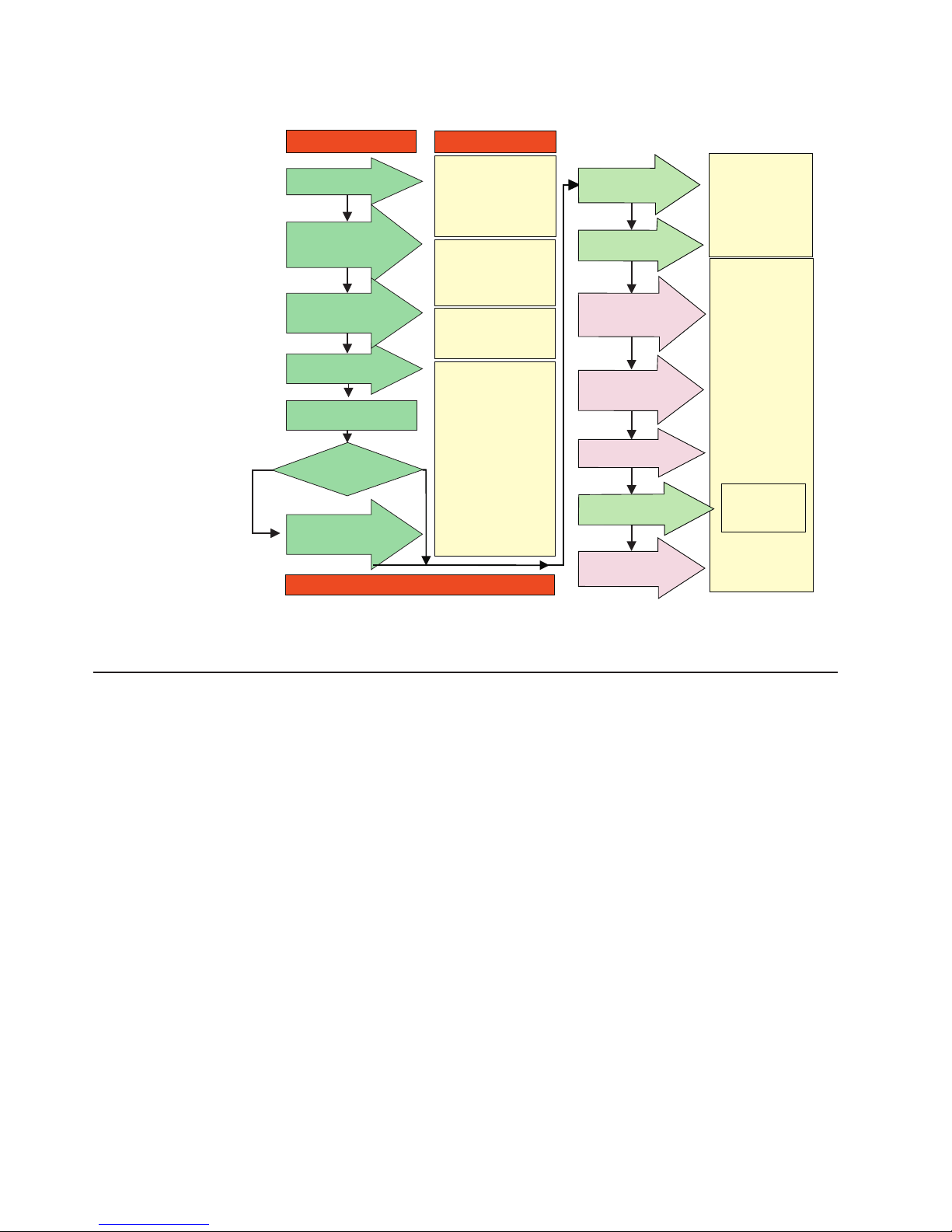
those steps.
Install Process
Plan Installation
Install Storage
Server/RAID Controller
Enclosure(s) in Rack
Install Storage
Expansion Unit(s)
Make FC Connections
Set Link Speed
(1 Gb only)
Determine
Management
Method
Out-of-Band
Install Network
Hardware; Prepare
Network Connection
* For pSeries Server and 6227 or 6228 HBA use only
In-Band
Documentation
FC Planning and
*
Integration: User's Guide
and Svc Info
FAStT SM V. 7.10
Concepts Guide
FAStT Storage Svr
Installation Guide
FAStT RAID Controller
Enclosure Unit Install
and User's Guide
FAStT Storage Exp Units
Install and User's Guides
FAStT and HBA Install
and User's Guides
FAStT Fibre Channel
Storage Server
Installation Guides
Fibre Channel Cabling
Instructions
Connect Power and
Start Server
Verify Server
operation w/ LEDs
Prepare for
Installation of
SM Software
Install and Verify SM SW
on Host and
Workstation
Complete SM SW
Installation
Configure Storage
Hardware
Configure Storage
Subsystems on Host
FAStT Storage Server
Installation Guides
Fibre Channel
Hardware Maintenance
and Problem
Determination Guide
FAStT Storage
Manager Installation
and Support
OS Guides
FAStT Remote Mirror
Option Installation
and User's Guide
Online Help
Figure 1. Installation process flow by current publications
FAStT documentation
The following tables present an overview of the FAStT Storage Manager and the
FAStT900, FAStT700, FAStT600, FAStT500, and FAStT200 Fibre Channel Storage
Server product libraries, as well as other related documents. Each table lists
documents that are included in the libraries and what common tasks they address.
Click on active links in the tables to access those documents currently available on
the Internet.
xvi IBM TotalStorage FAStT600 Fibre Channel Storage Server: Installation and User’s Guide
Page 19

FAStT Storage Manager Version 8.3 library
Table 1 associates each document in the FAStT Storage Manager library with its
related common user tasks.
Table 1. TotalStorage FAStT Storage Manager Version 8.3 titles by user tasks
Title User Tasks
IBM TotalStorage
FAStT600 and
Storage Manager
8.3 Library Guide
and Common Index,
GC26-7562
IBM TotalStorage
FAStT Storage
Manager 8.3
Installation and
Support Guide for
Microsoft
NT
®
®
Windows
, Windows 2000,
and Windows Server
2003, GC26-7579
IBM TotalStorage
FAStT Storage
Manager 8.3
Installation and
Support Guide for
Linux, GC26-7519
IBM TotalStorage
FAStT Storage
Manager 8.3
Installation and
Support Guide for
Novell NetWare,
GC26-7520
IBM TotalStorage
FAStT Storage
Manager 8.3
Installation and
Support Guide for
UNIX and
®
Environments,
AIX
GC26-7521
IBM FAStT Remote
Mirror Option
Installation and
User’s Guide,
48P9821
IBM FAStT Storage
Manager Script
Commands (see
product CD)
Planning Hardware
Installation
UU U U U U
UUU
UUU
UUU
UUU
UUUU
Software
Installation
Configuration Operation and
U
Administration
Diagnosis and
Maintenance
About this document xvii
Page 20

Table 1. TotalStorage FAStT Storage Manager Version 8.3 titles by user tasks (continued)
Title User Tasks
IBM FAStT Storage
Manager Version
7.10 Concepts
Guide, 25P1661
Planning Hardware
Installation
UU U U U U
Software
Installation
Configuration Operation and
Administration
Diagnosis and
Maintenance
xviii IBM TotalStorage FAStT600 Fibre Channel Storage Server: Installation and User’s Guide
Page 21

FAStT900 Fibre Channel Storage Server library
Table 2 associates each document in the FAStT900 Fibre Channel Storage Server
library with its related common user tasks.
Table 2. TotalStorage FAStT900 Fibre Channel Storage Server document titles by user tasks
Title User Tasks
IBM TotalStorage
FAStT900
Installation and
Support Guide,
GC26-7530
IBM TotalStorage
FAStT900 Fibre
Channel Cabling
Instructions,
24P8135
IBM TotalStorage
FAStT900 Storage
Server User’s Guide,
GC26-7534
IBM TotalStorage
FAStT FC2-133 Dual
Port Host Bus
Adapter Installation
and User’s Guide,
GC26-7532
IBM FAStT FC2-133
Host Bus Adapter
Installation and
User’s Guide,
48P9823
IBM TotalStorage
FAStT900 Rack
Mounting
Instructions,
19K0900
IBM Fibre Channel
Planning and
Integration: User’s
Guide and Service
Information,
SC23-4329
IBM FAStT
Management Suite
Java User’s Guide,
32P0081
IBM TotalStorage
FAStT Fibre Channel
Hardware
Maintenance Manual
and Problem
Determination
Guide, GC26-7528
Planning Hardware
Installation
UU U
UU
UU
UU
UU
UU U U
Software
Installation
Configuration Operation and
Administration
UUU
Diagnosis and
Maintenance
UU
U
About this document xix
Page 22

FAStT700 Fibre Channel Storage Server library
Table 3 associates each document in the FAStT700 Fibre Channel Storage Server
library with its related common user tasks.
Table 3. TotalStorage FAStT700 Fibre Channel Storage Server document titles by user tasks
Title User Tasks
IBM FAStT700
Installation and
Support Guide,
32P0171
IBM FAStT700 Fibre
Channel Cabling
Instructions,
32P0343
IBM FAStT700 Fibre
Channel Storage
Server User’s Guide,
32P0341
IBM EXP700
Storage Expansion
Unit Installation and
User’s Guide,
32P0178
IBM FAStT FC2-133
Dual Port Host Bus
Adapter Installation
and User’s Guide,
GC26-7532
IBM TotalStorage
FAStT FC2-133 Host
Bus Adapter
Installation and
User’s Guide,
48P9823
IBM FAStT
Management Suite
Java User’s Guide,
32P0081
IBM Fibre Channel
Hardware
Maintenance
Manual, 19K6130
IBM Fibre Channel
Problem
Determination
Guide, 48P9804
Planning Hardware
Installation
UU U
UU
UU U U U
UU
UU
Software
Installation
Configuration Operation and
Administration
UUU
Diagnosis and
Maintenance
UU
U
U
xx IBM TotalStorage FAStT600 Fibre Channel Storage Server: Installation and User’s Guide
Page 23

FAStT600 Fibre Channel Storage Server library
Table 4 associates each document in the FAStT600 Fibre Channel Storage Server
library with its related common user tasks.
Table 4. TotalStorage FAStT600 Fibre Channel Storage Server document titles by user tasks
Title User Tasks
IBM TotalStorage
FAStT600 Fibre
Channel Storage
Server Installation
and User’s Guide,
GC26-7531
IBM TotalStorage
FAStT Fibre Channel
Hardware
Maintenance Manual
and Problem
Determination
Guide, GC26-7528
IBM TotalStorage
FAStT FC2-133 Dual
Port Host Bus
Adapter Installation
and User’s Guide,
GC26-7532
IBM TotalStorage
FAStT600 Rack
Mounting
Instructions,
24P8125
IBM TotalStorage
FAStT600 Cabling
Instructions,
24P8126
Planning Hardware
Installation
UU U
UU
UU
UU
Software
Installation
Configuration Operation and
Administration
Diagnosis and
Maintenance
U
About this document xxi
Page 24

FAStT500 Fibre Channel Storage Server library
Table 5 associates each document in the FAStT500 Fibre Channel Storage Server
library with its related common user tasks.
Table 5. TotalStorage FAStT500 and FAStT High Availablity Storage Server document titles by user tasks
Title User Tasks
IBM FAStT500 RAID
Controller Enclosure
Unit User’s Guide,
48P9847
IBM FAStT EXP500
Storage Expansion
Unit Installation and
User’s Guide,
59P5637
IBM FAStT500 RAID
Controller Enclosure
Unit Installation
Guide, 59P6244
IBM FAStT FC2-133
Dual Port Host Bus
Adapter Installation
and User’s Guide,
GC26-7532
IBM TotalStorage
FAStT FC2-133 Host
Bus Adapter
Installation and
User’s Guide,
48P9823
IBM FAStT
Management Suite
Java User’s Guide,
32P0081
IBM Fibre Channel
Hardware
Maintenance
Manual, 19K6130
IBM Fibre Channel
Problem
Determination
Guide, 48P9804
Planning Hardware
Installation
UU U U U
UU
UU
UU
Software
Installation
Configuration Operation and
Administration
UUU
UU
Diagnosis and
Maintenance
U
U
xxii IBM TotalStorage FAStT600 Fibre Channel Storage Server: Installation and User’s Guide
Page 25

FAStT200 Fibre Channel Storage Server library
Table 6 associates each document in the FAStT200 Fibre Channel Storage Server
library with its related common user tasks.
Table 6. TotalStorage FAStT200 and FAStT High Availablity Storage Server document titles by user tasks
Title User Tasks
IBM FAStT200 and
FAStT200 HA
Storage Servers
Installation and
User’s Guide,
59P6243
IBM FAStT200 Fibre
Channel Cabling
Instructions,
21P9094
IBM FAStT FC2-133
Dual Port Host Bus
Adapter Installation
and User’s Guide,
GC26-7532
IBM FAStT FC2-133
Host Bus Adapter
Installation and
User’s Guide,
48P9823
IBM FAStT
Management Suite
Java User’s Guide,
32P0081
IBM Fibre Channel
Hardware
Maintenance
Manual, 19K6130
IBM Fibre Channel
Problem
Determination
Guide, 48P9804
Planning Hardware
Installation
UU U U
UU
UU
UU
Software
Installation
Configuration Operation and
Administration
UU
Diagnosis and
Maintenance
U
U
About this document xxiii
Page 26

FAStT related documents
Table 7 associates each of the following documents related to FAStT operations
with its related common user tasks.
Table 7. TotalStorage FAStT related document titles by user tasks
Title User Tasks
IBM Safety
Information,
P48P9741
®
IBM Netfinity
Channel Cabling
Instructions,
19K0906
IBM Fibre Channel
SAN Configuration
Setup Guide,
25P2509
Fibre
Planning Hardware
Installation
U
UUUU
Software
Installation
Configuration Operation and
Notices used in this document
This document contains the following notices designed to highlight key information:
v Note: These notices provide important tips, guidance, or advice.
v Important: These notices provide information that might help you avoid
inconvenient or problem situations.
v Attention: These notices indicate possible damage to programs, devices, or
data. An attention notice is placed just before the instruction or situation in which
damage could occur.
v Caution: These statements indicate situations that can be potentially hazardous
to you. A caution statement is placed just before the description of a potentially
hazardous procedure step or situation.
v Danger: These statements indicate situations that can be potentially lethal or
extremely hazardous to you. A danger statement is placed just before the
description of a potentially lethal or extremely hazardous procedure step or
situation.
Administration
U
Diagnosis and
Maintenance
Getting information, help, and service
If you need help, service, or technical assistance or just want more information
about IBM products, you will find a wide variety of sources available from IBM to
assist you. This section contains information about where to go for additional
information about IBM and IBM products, what to do if you experience a problem
with your IBM Eserver xSeries
service, if it is necessary.
Before you call
Before you call, make sure that you have taken these steps to try to solve the
problem yourself:
v Check all cables to make sure that they are connected.
v Check the power switches to make sure that the system is turned on.
xxiv IBM TotalStorage FAStT600 Fibre Channel Storage Server: Installation and User’s Guide
™
or IntelliStation®system, and whom to call for
Page 27

v Use the troubleshooting information in your system documentation and use the
diagnostic tools that come with your system.
v Check for technical information, hints, tips, and new device drivers at the
following Web site:
www.ibm.com/storage/techsup.htm
v Use an IBM discussion forum on the IBM Web site to ask questions.
You can solve many problems without outside assistance by following the
troubleshooting procedures that IBM provides in the online help or in the documents
that are provided with your system and software. The information that comes with
your system also describes the diagnostic tests that you can perform. Most xSeries
and IntelliStation systems, operating systems, and programs come with information
that contains troubleshooting procedures and explanations of error messages and
error codes. If you suspect a software problem, see the information for the
operating system or program.
Using the documentation
Information about the xSeries or IntelliStation system and preinstalled software, if
any, is available in the documents that come with your system. This includes printed
documents, online documents, readme files, and help files. See the troubleshooting
information in your system documentation for instructions for using the diagnostic
programs. The troubleshooting information or the diagnostic programs might tell you
that you need additional or updated device drivers or other software.
Web sites
IBM maintains pages on the World Wide Web where you can get the latest
technical information and download device drivers and updates.
v For FAStT information, go to the following Web site:
www.ibm.com/storage/techsup.htm The support page has many sources of
information and ways for you to solve problems, including:
– Diagnosing problems, using the IBM Online Assistant
– Downloading the latest device drivers and updates for your products
– Viewing frequently asked questions (FAQ)
– Viewing hints and tips to help you solve problems
– Participating in IBM discussion forums
– Setting up e-mail notification of technical updates about your products
v You can order publications through the IBM Publications Ordering System at:
www.elink.ibmlink.ibm.com/public/applications/publications/cgibin/pbi.cgi/
v For the latest information about IBM xSeries products, services, and support, go
to the following Web site:
www.ibm.com/eserver/xseries/
v For the latest information about IBM pSeries products, services, and support, go
to the following Web site:
www.ibm.com/eserver/pseries/
v For the latest information about the IBM IntelliStation information, go to the
following Web site:
www.ibm.com/pc/intellistation/
v For the latest information about operating system and HBA support, clustering
support, SAN fabric support, and Storage Manager feature support, see the
TotalStorage FAStT Interoperability Matrix at the following Web site:
About this document xxv
Page 28

www.storage.ibm.com/disk/fastt/pdf/0217-03.pdf
Software service and support
Through IBM Support Line, for a fee you can get telephone assistance with usage,
configuration, and software problems with xSeries servers, IntelliStation
workstations, and appliances. For information about which products are supported
by Support Line in your country or region, go to the following Web site:
www.ibm.com/services/sl/products/
For more information about the IBM Support Line and other IBM services, go to the
following Web sites:
v www.ibm.com/services/
v www.ibm.com/planetwide/
Hardware service and support
You can receive hardware service through IBM Integrated Technology Services or
through your IBM reseller, if your reseller is authorized by IBM to provide warranty
service. Go to the following Web site for support telephone numbers:
www.ibm.com/planetwide/
In the U.S. and Canada, hardware service and support is available 24 hours a day,
7 days a week. In the U.K., these services are available Monday through Friday,
from 9 a.m. to 6 p.m.
Fire suppression systems
|
|
|
|
|
|
|
|
|
|
A fire suppression system is the responsibility of the customer. The customer’s own
insurance underwriter, local fire marshal, or a local building inspector, or both,
should be consulted in selecting a fire suppression system that provides the correct
level of coverage and protection. IBM designs and manufactures equipment to
internal and external standards that require certain environments for reliable
operation. Because IBM does not test any equipment for compatibility with fire
suppression systems, IBM does not make compatibility claims of any kind nor does
IBM provide recommendations on fire suppression systems.
Table 9 on page 8 lists the environmental specifications for the FAStT600.
How to send your comments
Your feedback is important to help us provide the highest quality information. If you
have any comments about this document, you can submit them in one of the
following ways:
v E-mail
Submit your comments electronically to:
starpubs@us.ibm.com
Be sure to include the name and order number of the document and, if
applicable, the specific location of the text that you are commenting on, such as
a page number or table number.
v Mail or fax
xxvi IBM TotalStorage FAStT600 Fibre Channel Storage Server: Installation and User’s Guide
Page 29

Fill out the Readers’ Comments form (RCF) at the back of this document and
return it by mail or fax (1-800-426-6209) or give it to an IBM representative. If the
RCF has been removed, you can address your comments to:
International Business Machines Corporation
RCF Processing Department
Dept. M86/Bldg. 050-3
5600 Cottle Road
San Jose, CA 95193-0001
U.S.A
When you send information to IBM, you grant IBM a nonexclusive right to use or
distribute the information in any way it believes appropriate without incurring any
obligation to you.
About this document xxvii
Page 30

xxviii IBM TotalStorage FAStT600 Fibre Channel Storage Server: Installation and User’s Guide
Page 31

Chapter 1. Introduction
IBM FAStT (Fibre Array Storage Technology) solutions support the large and
growing data storage requirements of business-critical applications. These scalable
IBM FAStT solutions offer you data access and protection to meet your existing
enterprise storage requirements and prepare for the future.
Fibre channel is a new technology, similar to a high-speed network, that you can
use to connect large amounts of disk storage to a server or cluster of servers. Fibre
Channel technology supports increased performance, scalability, availability, and
distance for attaching storage subsystems to network servers. The storage server
provides for the attachment of Fibre Channel disk drives to give superior
performance and redundancy.
Fibre channel technology supports applications that require large amounts of disk
storage that is shared by two or more servers. With fibre channel, you can see a
higher throughput rate over longer distances than is possible with small computer
system interface (SCSI) or with serial storage architecture (SSA) technology.
The IBM TotalStorage FAStT600 Storage Server (Machine Type 1722, Models 60U
and 60X) comes with two RAID controllers, two power supplies, and two cooling
units and provides dual, redundant controllers, redundant cooling, redundant power,
and battery backup of the RAID controller cache. The FAStT600 Storage Server is
designed to provide maximum host and drive side redundancy. Each RAID
controller supports direct attachment of one host containing one or two host
adapters.
FAStT600 supports up to fourteen internal disk drive modules, supporting over 2
TBs of storage capacity. Additional storage can be added to the FAStT600 with up
to two FAStT EXP700 Expansion Units using optional EXP700 Attachment features
(feature number 7360, or features number 7361 and number 7362). Utilizing these
features, up to 42 disk drives can be attached to the FAStT600 with individual drive
module capacities ranging from 36.4 GB to 146.8 GB.
After you review the introductory information that is provided in this chapter, go to
Chapter 2, “Installing and configuring the storage server”, on page 11 to begin the
installation process.
Features at a glance
Table 8 on page 2 summarizes the features of the storage server. For a list of the
operating specifications, such as weight, height, and heat output, see Table 9 on
page 8.
© Copyright IBM Corp. 2003 1
Page 32

Table 8. Features at a glance
General
v Modular components:
– High-capacity disk drives
– RAID controllers
– Power supplies
– Cooling fans
v Technology:
– Support for disk arrays
– Support for clustering
– Fibre Channel host interface
– Redundant data storage, cooling
system, power system, and RAID
controllers
– Hot-swap technology for drives,
power supplies, fans, and RAID
controllers
Clustering support
Clustering is a means of sharing array groups among controllers to provide
redundancy of controllers and servers. This redundancy is important if a hardware
component fails. If a hardware component failure occurs in a cluster, another server
takes ownership of the array group.
v User interface:
– Built-in power, activity, and fault Light
Emitting Diodes (LEDs)
– Identification labeling on customer
replaceable units (CRUs), rear LEDs,
switches, and connectors
– Easy-to-replace drives, power
supplies, RAID controllers, and fans
Disk drive storage
2Gb Fibre Channel enclosure
Maximum drives per storage server: 14
Attached Expansion Units
Attachment of drive expansion units
(EXP700’s) requires one or more
EXP700 Attachment option (or feature)
upgrades for the FAStT600
2 Gb connection only
RAID controllers
v Technology and interfaces:
– Fibre channel: 40-pin FC disk drives
– Fibre Channel interface: six small
form-factor pluggable (SFP) modules
for incoming and outgoing FC cables
(three SFPs on each RAID
controller)
– Two 2Gb Fibre Channel host side
connections per controller
Clustering requires software specific to your operating system. For more information
about clustering, go to the following Web site:
www.pc.ibm.com/us/compat/nos/cert.shtml
Inventory checklist
After you unpack the storage server, verify that you have the following items:
Hardware
IBM FAStT600 Storage Server comes with the following components:
v Two RAID controllers
v Two fan units
v Two power supplies
v Two power cords
v 14 filler panels
v Rack-mounting hardware kit (1)
– Two rails (right and left assembly)
– Ten M6 screws
– Ten M6 cage nuts
– Ten M6 clip nuts
Software and documentation:
v IBM FAStT Storage Manager Version 8.3 CD including:
– IBM FAStT Storage Manager Version 8.3
2 IBM TotalStorage FAStT600 Fibre Channel Storage Server: Installation and User’s Guide
Page 33

– Publications and online help in Adobe Acrobat Portable Document Format
(PDF)
For a list of available IBM FAStT publications, see “FAStT documentation” on
page xvi.
v Rack Mounting Assembly kit, including:
– Rack mounting installation instructions
– Rack mounting template (for aligning the rails properly)
– White tape dots for marking the holes in the rack
v Fibre Channel cabling instructions
If an item is missing or damaged, contact your IBM reseller or your IBM marketing
representative.
If you have not already done so, record your storage server serial number in the
table in “Records”, on page 77.
Handling static-sensitive devices
Attention: Static electricity can damage electronic devices and your system. To
avoid damage, keep static-sensitive devices in their static-protective package until
you are ready to install them.
To reduce the possibility of electrostatic discharge (ESD), observe the following
precautions:
v Limit your movement. Movement can cause static electricity to build up around
you.
v Handle the device carefully. Hold it by its edges or its frame.
v Do not touch solder joints, pins, or exposed printed circuitry.
v Do not leave the device where others can handle and possibly damage the
device.
v While the device is still in its static-protective package, you should hold the
device and touch an unpainted metal part of the system unit for at least two
seconds. This drains static electricity from the package and from your body.
v Remove the device from its package and install it directly into your system unit
without setting it down. If it is necessary to set the device down, place it in its
static-protective package. Do not place the device on your system unit cover or
on a metal table.
v Take additional care when handling devices during cold weather because heating
reduces indoor humidity and increases static electricity.
Best practices guidelines
|
|
|
|
|
|
|
|
|
To ensure optimal operation of your system, always follow these best practices
guidelines:
v Back up the data on your storage drives periodically.
v To maintain power redundancy, plug the FAStT600 Storage Server’s right and the
left power supplies into two independent external power circuits through ac
distribution units inside a rack cabinet or directly into external receptacles.
Similarly, the right and left power supplies of the FAStT drive enclosures attached
to the FAStT600 Storage Server should be plugged into the same two
independent external power circuits as the FAStT600 Storage Server. This
Chapter 1. Introduction 3
Page 34

|
|
|
|
|
|
|
|
|
|
|
|
|
|
|
|
|
|
|
|
|
|
|
|
|
|
|
|
|
ensures that the FAStT600 Storage Server and all its attached drive enclosures
will have power if only one power circuit is available. In addition, having all the
right or all the left power supplies plug into the same power circuit will enable the
components in the storage subsystem to power on simultaneously during an
unattended restoration of power. See Figure 32 on page 34 for an example of
redundant power connections.
v Before any planned system shutdown or after any system changes (additions,
removals, or modifications), save controller subsystem profiles as explained in
the Storage Manager guide for your operating system.
v Ensure that your system is in an optimal state before shutting down. Never turn
the power off if any fault light is lit; be sure to resolve any error conditions before
you shut down the system.
v During any maintenance or attended power-up procedure, carefully follow the
power-up sequence listed in “Turning on the storage server” on page 38. Each
component of the subsystem should be checked that it is powered-on in the
proper order during this entire power-up procedure to ensure the controller will be
able to optimally access all of your storage subsystems.
v The storage subsystem supports simultaneous power-up to the system
components; however, you should always follow the power-up sequence listed in
“Turning on the storage server” on page 38 during any attended power-up
procedure.
v A storage system in an optimal state should recover automatically from an
unexpected shutdown and unattended simultaneous restoration of power to
system components. After power is restored, call IBM support if any of the
following conditions occur:
– The storage subsystem logical drives and arrays are not displayed in the
Storage Manager graphical user interface (GUI).
– The storage subsystem logical drives and arrays do not come online.
– The storage subsystem logical drives and arrays seem to be degraded.
Storage server components
The following sections show the components of the storage server.
The hot-swap features of the storage server enable you to remove and replace hard
disk drives, power supplies, RAID controllers, and fans without turning off the
storage server. Therefore, you can maintain the availability of your system while a
hot-swap device is removed, installed, or replaced.
Front view
Figure 2 on page 5 shows the components and controls on the front of the storage
server.
4 IBM TotalStorage FAStT600 Fibre Channel Storage Server: Installation and User’s Guide
Page 35

Power-on LED
General-system-
error LED
Locator LED
Hot-swap
drive CRU
Tray handle
Figure 2. Front controls and components
Latch
Power-on LED
When on, this green light indicates that the unit has good dc power.
General-system-error LED
When on, this amber LED indicates that the storage server has a fault,
such as in a power supply, fan unit, or hard disk drive.
Note: If the General-system-error LED is on continuously (not flashing),
there is a problem with the storage server. Use the
storage-management software to diagnose and repair the problem.
For more information, see “Checking the LEDs” on page 42.
Locator LED
When on, this blue light indicates the storage-management software is
locating the server.
Hot-swap drive CRU
You can install up to 14 hot-swap drive customer replaceable units (CRUs)
in the storage server. Each drive CRU consists of a hard disk drive and
tray.
Drive activity LED
Drive fault LED
Filler panel
Drive activity LED
Drive fault LED
Latch This multipurpose blue latch releases or locks the drive CRU in place.
Tray handle
The storage server comes without drives installed and contains filler panels
in the unused drive bays. Before installing new drives, you must remove the
filler panels and save them. Each of the 14 bays must always contain either
a filler panel or a drive CRU to ensure proper cooling, air ventilation, and
EMI compliance.
Each drive CRU has a green Drive activity LED. When flashing, this green
LED indicates drive activity. When on continuously, this green LED indicates
that the drive is properly installed.
Each drive CRU has an amber Drive fault LED. When on, this amber LED
indicates a drive failure. When flashing, this amber LED indicates that a
drive identify is in progress.
You can use this multipurpose handle to insert and remove a drive CRU in
the bay.
Chapter 1. Introduction 5
Page 36

Back view
For information on how to install and replace drive CRUs, see “Working with
hot-swap drives” on page 49. For more information about the LEDs, see “Checking
the LEDs” on page 42.
Figure 3 shows the components at the back of the storage server.
Hot-swap fan bays
Raid controllers
Hot-swap
power supplies
Figure 3. Back view of FAStT600 storage server
RAID controller
Each RAID controller contains three ports for Small Form-Factor Pluggable
(SFP) modules that connect to the Fibre Channel cables. Two SFPs can
connect to two host systems. The third SFP is used to connect additional
expansion units to the storage server.
Each RAID controller also contains a battery to maintain cache data in the
event of a power failure. For more information, see “Cache memory and
RAID controller battery” on page 46.
Hot-swap fans
The storage server has two interchangeable hot-swap and redundant fan
CRUs. Each fan CRU contains two fans. If one fan CRU fails, the second
fan CRU continues to operate. Both fan CRUs must be installed to maintain
proper cooling within the storage server, even if one fan CRU is not
operational.
Hot-swap power supplies
The storage server comes with two hot-swap power supplies. Both power
supplies must be installed to maintain proper cooling.
Interface ports and switches
Figure 4 on page 7 shows the ports and switches on the back of the storage server.
6 IBM TotalStorage FAStT600 Fibre Channel Storage Server: Installation and User’s Guide
Page 37

Ethernet
Host port 2
Host port 1
Expansion port
Serial port Serial port
Host port 2
Host port 1
Ethernet
Expansion port
AC power
connector
Figure 4. Interface ports and switches
AC power
switch
Server ID
switch
RAID controller
Each RAID controller contains several connectors and LEDs. Each
controller has two host ports and one expansion port for connecting the
storage server to hosts or expansion units. You first insert SFPs into the
ports and then connect the Fibre Channel cables.
Host ports
The host ports are used to connect a Fibre Channel cable from the host
systems. You first insert an SFP into the port and then connect a Fibre
Channel cable. The two host ports in each controller are independent. They
are not connected in the controller module as they would be in a hub
configuration.
Ethernet port
The Ethernet port is for an RJ-45 10BASE-T or 100BASE-T Ethernet
connection. Use the Ethernet connection to directly manage storage
subsystems.
Expansion port
The expansion port is used to connect additional expansion units to the
RAID controllers. You first insert a SFP into the port and then connect a
fibre channel cable.
AC power
connector
AC power
switch
Serial port
Server ID switch
Note: For controller firmware version 05.33.xx.xx, both host and expansion ports
operate at 2 Gbps only.
Note: You must purchase the option to enable the attachment of up to two
FAStT EXP700 Expansion Units using optional EXP700 Attachment
features (feature number 7360, or features number 7361 and
number 7362).
The serial port is used by service personnel to perform diagnostic
operations on the RAID controllers.
The Server ID switch settings range from 0 through 7, and unique IDs
ranging from 00 through 77 can be set.
Chapter 1. Introduction 7
Page 38

Operating specifications
The following table summarizes the operating specifications of the storage server.
Table 9. FAStT600 storage server operating specifications
Size (with front panel and without
mounting rails)
v Depth: 59.7 cm (23.6 in)
v Height: 13.2 cm (5.2 in)
v Width: 48 cm (18.9 in)
Heat output
v 390 watts (1330 BTU/hr)
Weight
v Standard storage server as shipped:
39.10 kg (86.2 lb)
v Unit weight: 31.48 kg (69.4 lb)
Electrical input
v Sine-wave input (50 to 60 Hz) is
required
v Input voltage:
– Low range:
- Minimum: 90 V ac
- Maximum: 136 V ac
– High range:
- Minimum: 198 V ac
- Maximum: 264 V ac
– Input kilovolt-amperes (kVA)
approximately:
- Minimum configuration: 0.06 kVA
- Maximum configuration: 0.37 kVA
Environment
v Air temperature:
– Storage server on:
10° to 35°C
(50° to 95°F)
Altitude: 0 to 914 m (3000 ft.)
– Storage server on:
10° to 32°C
(50° to 90°F)
Altitude: 914 m (3000 ft.) to 2133 m
(7000 ft.)
v Humidity:
– 8% to 80%
Acoustical noise emissions values For
open bay (0 drives installed) and typical
system configurations (14 hard disk drives
installed).
v Sound power (idling):
– 6.3 bels (open bay)
– 6.5 bels (typical)
v Sound power (operating):
– 6.3 bels (open bay)
– 6.8 bels (typical)
v Sound pressure (idling):
– 47 dBA (open bay)
– 49 dBA (typical)
v Sound pressure (operating):
– 47 dBA (open bay)
– 53 dBA (typical)
These levels are measured in controlled
acoustical environments according ISO
7779 and are reported in accordance with
ISO 9296. The declared sound power
levels indicate an upper limit, below which
a large portion of machines operate.
Sound pressure levels in your location
might exceed the average 1-meter values
stated because of room reflections and
other nearby noise.
Heat output, airflow, and cooling
The maximum heat output of the FAStT600 is 390 watts (1330 BTU/hr). Each
FAStT600 (machine type 1722) and drive expansion (EXP700) rack-mounted unit
requires an airflow of 2.5 m
temperature to all racks is recommended to be in the range 10°C through 35°C
(50°F through 95°F), with a recommended operating temperature of 22°C (72°F).
When racks that contain many 1722 units are to be installed together, the following
requirements must be met to ensure that the 1722 units are adequately cooled:
v Air enters at the front of the rack and leaves at the back. To prevent the air that
is leaving the rack from entering the intake of another piece of equipment, racks
must be positioned in alternate rows, back-to-back and front-to-front. This
arrangement is known as “Cold Aisle / Hot Aisle” and is shown in Figure 5 on
page 9.
v Where racks are in rows, each rack must touch the rack that is next to it to
reduce the amount of hot air that can flow around from the back of the rack into
the intakes of the 1722 units that are in that rack. It is recommended that Suite
Attach Kits be used to completely seal any gaps that remain between the racks.
For details of Suite Attach Kits, contact your marketing representative.
v Where racks are in rows front-to-front or back-to-back, a gap of at least 1220 mm
(48 in.) must separate the rows across the cold aisle.
3
per minute (87 ft3per minute). The input air
8 IBM TotalStorage FAStT600 Fibre Channel Storage Server: Installation and User’s Guide
Page 39

v To ensure correct airflow in each rack, the rack filler plates must be installed in
unused positions. Also, all the gaps in the front of the racks must be sealed,
including the gaps between the 1722 units.
back
T42 racks
front
1220 mm cold
aisle width
Air
Cold aisle
front
T42 racks
back
conditioner
Hot aisle
back
T42 racks
front
Airflow
Figure 5. Example of Cold Aisle/Hot Aisle Rack Configuration
Perforated tiles
or gratings
2440 mm between
center lines of hot
and cold aisle
Chapter 1. Introduction 9
Page 40

10 IBM TotalStorage FAStT600 Fibre Channel Storage Server: Installation and User’s Guide
Page 41

Chapter 2. Installing and configuring the storage server
This chapter contains information about how to prepare, install, and configure the
storage subsystem.
Getting started
Use the following list to prepare a storage server for installation:
1. Prepare the site to meet all area, environmental, power, and site requirements.
For more information, see “Operating specifications” on page 8.
2. Move the storage server and its rack cabinet to the site.
3. Remove the storage server from its shipping container and check the contents
(for a list of items, see “Inventory checklist” on page 2.) If any items are missing,
contact your IBM reseller before you proceed.
4. Assemble the tools and equipment that you will need for installation. These
might include:
v Power cords (come with the storage server)
v Screwdrivers (various sizes)
v Antistatic protection (such as a grounding wrist strap)
v SFPs
v Fibre Channel and Ethernet interface cables and cable straps
v Rack-mounting hardware (comes with the storage server)
v Storage-management software to configure the storage subsystems (comes
with the storage server on the IBM TotalStorage FAStT Storage Manager 8.3
installation CD.)
Rack mounting instructions and a template for aligning the holes in the rails and the
rack come with the storage server. If you have misplaced these items, see “Rack
mounting template and instructions”.
After you install the storage server in the rack and configure the storage server, go
to Chapter 3, “Cabling the storage server”, on page 27.
Rack mounting template and instructions
A rack mounting template and instructions come with the storage server. If you have
misplaced these items, use the following template and instructions.
© Copyright IBM Corp. 2003 11
Page 42
FRONT
Rack Mounting
Template
Bezel
()Front Left
Rail assembly
()Front Left
Figure 6. Front rack mounting template
()Front Right
Bezel
Rail assembly
()Front Right
12 IBM TotalStorage FAStT600 Fibre Channel Storage Server: Installation and User’s Guide
Page 43

REAR
Rack Mounting
Template
Rail assembly
()Rear Left
Figure 7. Rear rack mounting template
Rail assembly
()Rear Right
®
P/N 06P4631
Printed in the U.S.A.
Chapter 2. Installing and configuring the storage server 13
Page 44

Installing the storage server in a rack
Review the documentation that comes with the rack cabinet for safety and cabling
information. When you install the storage server in a rack, consider the following
factors:
v Ensure that the room air temperature is below 35°C (95°F).
v Do not block any air vents. Usually, leaving 15 cm (6 in.) of air space provides
proper airflow.
v Plan the device installation starting from the bottom of the rack.
v Do not extend more than one device out of the rack at the same time.
v Remove the rack doors and side panels to provide easier access during
installation.
v Connect all power cords to properly wired and grounded electrical outlets.
v Take precautions to prevent overloading the power outlets when you install
multiple devices in a rack.
Statement 4:
≥ 18 kg (39.7 lb) ≥ 32 kg (70.5 lb) ≥ 55 kg (121.2 lb)
CAUTION:
Use safe practices when lifting.
You will need a flat-blade and a Phillips screwdriver during the installation. The
following items come with your option. If any items are missing or damaged, contact
your place of purchase.
v Cage nuts (10)
v Clip nuts (10)
v M6 screws (10)
v Side rails (2)
Note: See the storage server documentation for handling guidelines before
removing any ESD-sensitive devices. Perform the following steps to install
the storage server in a rack. The first four steps for the installation procedure
involve removing some components from the storage server in order to
reduce the weight of the storage server for easier installation.
1. To remove a RAID controller, push down on the latch centered on the controller;
then, grasp the pull-rings on the levers and pull them to remove the RAID
controller and set it aside for later installation.
If you have a second RAID controller, repeat this step for the second controller.
14 IBM TotalStorage FAStT600 Fibre Channel Storage Server: Installation and User’s Guide
Page 45

1
1
Figure 8. RAID controller removal
2. To remove a hot-swap fan, slide the latch on the fan to unlock it; then pull the
handle and remove the fan from the storage server.
Repeat this step for the other fan and set both fans aside for later installation.
2
2
Figure 9. Hot-swap fan removal
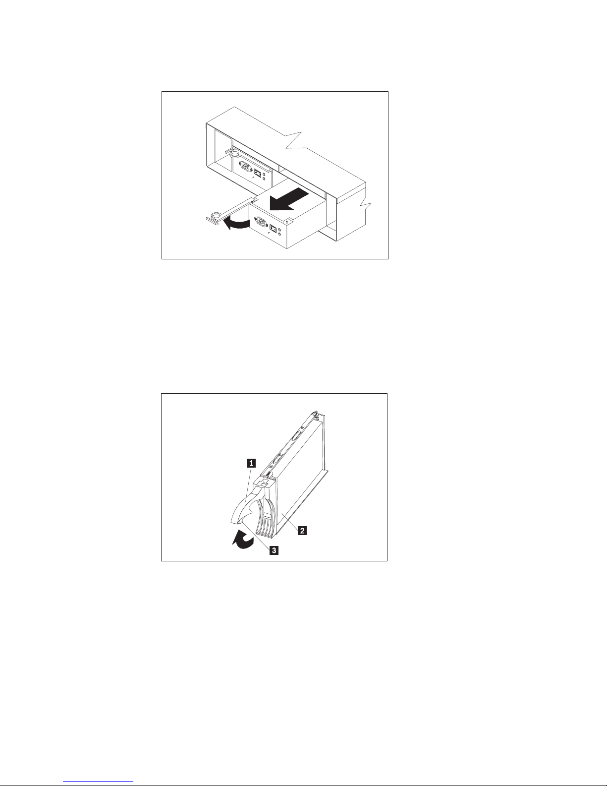
3. To remove a power supply, grasp the pull-ring on the power supply lever and
squeeze to release it; then pull the lever fully open and remove the power
supply from the storage server.
Repeat this step for the other power supply; then set both power supplies aside
for later installation.
Chapter 2. Installing and configuring the storage server 15
Page 46
thisstepforthesecondcontroller.
3
3
Figure 10. Power supply removal
4. To remove a hard disk drive 2, press the blue latch 3 and pull the handle
1 upwards; then carefully pull the drive from the storage server.
Note: Before you remove any hard disk drives, make sure that you mark their
location so that you can reinstall them in the same location.
Repeat this step for all hard disk drives.
4
Figure 11. Hard disk drive removal
5. Use the attached template and stickers to mark the appropriate holes on the
rack; then install clip nuts or cage nuts as required for the rack cabinet.
Note: Use the cage-nut-insertion tool or a flat-blade screwdriver to install cage
nuts.
16 IBM TotalStorage FAStT600 Fibre Channel Storage Server: Installation and User’s Guide
Page 47
5
5
Cage
Cage
nuts
Clip
Clip
nuts
n uts
n uts
Cage
Cage
nuts
n uts
Figure 12. Rack nut installation
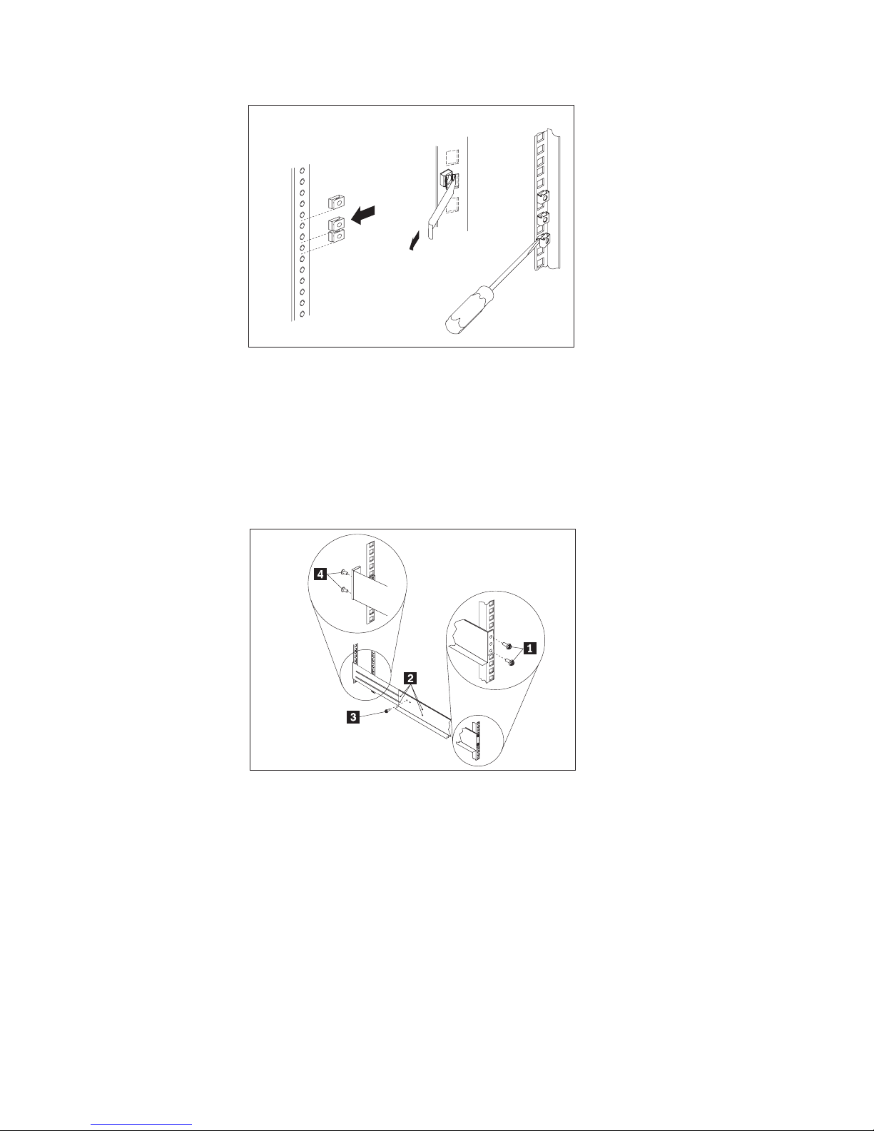
6. On the rail marked R, remove the 6/32 in. screw 3 and loosen the four screws
2; then hold the front of the rail against the outside of the right
rack-mounting-flange and loosely install two M6 screws 1.
Extend the rear of the rail outside of the rear rack-mounting-flange; then install
and tighten two M6 screws 4. Tighten the front screws 1 and repeat this
step for the other rail.
6
6
Figure 13. Rail extension
7. Tighten the rail adjustment screws 1 on both rails.
Chapter 2. Installing and configuring the storage server 17
Page 48

7
7
Figure 14. Rail adjustment screws
8. Remove the white screws and nuts 1 from the storage server bezel; then slide
the storage server into the rack. Align the bezel locator pins and attach the
bezel with two M6 screws 2; then install and tighten the 6-32 in. screws 3.
8
8
Figure 15. Server installation
9. Reverse step 1 through step 4 to reinstall the components that you removed.
See your storage server documentation to complete your installation. Store this
information with the storage server documentation for future use.
Setting server ID settings
The FAStT600 comes with a server ID switch that is used to identify the FAStT600
on a Fibre Channel loop. The server ID switch is located on the back of the unit, as
shown in Figure 16 on page 19.
18 IBM TotalStorage FAStT600 Fibre Channel Storage Server: Installation and User’s Guide
Page 49

Server ID Switch
Figure 16. Setting the Server ID
Server ID switch settings set the server ID to a value from 00 - 77. Server ID switch
X1 is for setting the ones position, and Server ID switch X10 is for setting the tens
position. The settings of the two server ID switches, when used together, provide a
two-digit ID of the server unit. The storage-management software uses the server
ID to provide a correlation between the storage-management graphics and the
physical storage unit. The ID indicates which physical unit corresponds to the
storage-management software status.
Use Server ID switches X10 and X1 to set the server-unit ID to any value from 0
through 7.
Note: Each server unit should have a unique ID if it is going to be connected to
other drive expansion units through the drive loop ports. The Server ID
setting is only valid for the drive loop. The amber Conflict LED (located on
the right-side of the switch) will be lit if there is another unit in the drive loop
that has the same ID setting as the server ID. See your storage server
documentation for more information.
Configuring the storage subsystem
You must configure the storage subsystem configuration after you install the storage
server in a rack. Use the information in the following sections to configure your
storage subsystem configuration.
Storage subsystem management methods
Before you configure the storage subsystem, determine which method of storage
subsystem management you want to use. You can manage the storage subsystems
in either of two ways: Host-agent management or Direct-management.
Chapter 2. Installing and configuring the storage server 19
Page 50
Host-agent management method:
This method uses host-agent software that is installed on the host server. You must
install at least one management station and a software-agent host. The
management station can be the host or a workstation on the Ethernet network. A
management station will have the client software installed. Figure 17 shows the
host-agent management method.
Controller
Controller
Host-agent
software
Fibre Channel
I/O path
Controller
Controller
Figure 17. Host-agent managed storage subsystems
Ethernet
Note: The client software is
Client software
Management station
(one or more)
installed on one or more
management systems,
or on the host computer.
20 IBM TotalStorage FAStT600 Fibre Channel Storage Server: Installation and User’s Guide
Page 51

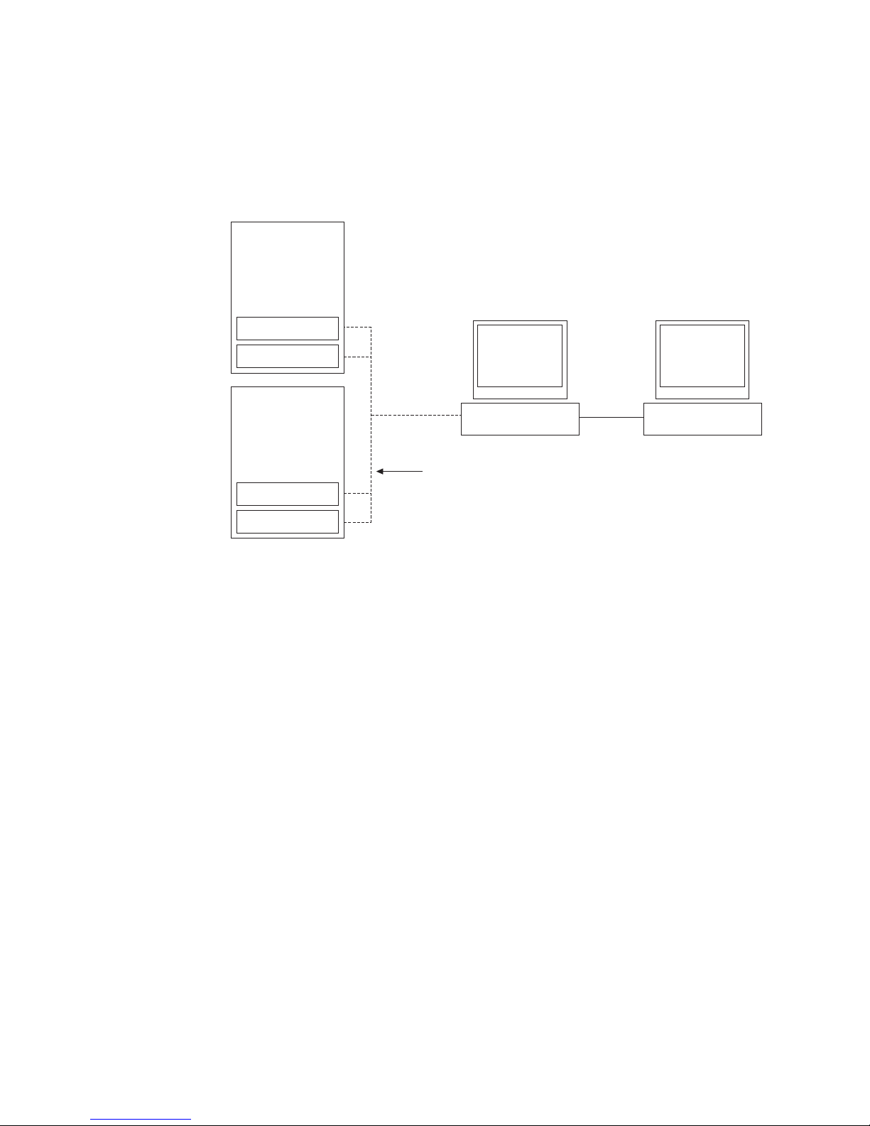
Direct-management method:
This method uses Ethernet connections from a management station to each
controller. You must install at least one management station. The management
station can be the host or a workstation on the Ethernet network. A management
station will have the client software installed. Attach Ethernet cables to each
management station (one pair per storage server). You will connect the cables to
each controller later when you install the storage server. Figure 18 shows the direct
management method.
Controller
Controller
Host computer
Fibre Channel
I/O path
Controller
Controller
Storage subsystems
Note: The client software is
installed on one or more
management systems,
or on the host computer.
Ethernet
Figure 18. Direct-managed storage subsystems
Fibre Channel connections
The storage server Fibre Channel consists of a host Fibre Channel loop and a drive
Fibre Channel loop. The host Fibre Channel loop provides the fibre path for host
attachment. It can consist of Fibre Channel cables, SFPs, host bus adapters, Fibre
Channel switches, and RAID controllers. The drive Fibre Channel loop provides the
fibre path to the hard disk drives (HDDs). The drive Fibre Channel loop consists of
Fibre Channel HDDs and optional drive expansion units, Fibre Channel cables, and
SFPs.
The FAStT600 Storage Server supports redundant disk-drive-loop configurations.
Each RAID controller has three SFP ports. These SFP ports are labeled ″Host 1″,
″Host 2″, and ″Expansion″. You can build a redundant drive loop by connecting one
or more expansion units to the redundant RAID controllers. Then, use dual
Management station
Chapter 2. Installing and configuring the storage server 21
Page 52

fiber-optic cables to connect one expansion unit to another in a daisy-chain. For
more information about adding expansion units, see “Connecting additional
expansion units” on page 35.
Fibre Channel loop configurations
You must determine how the host systems will connect to the storage server. You
can connect up to two host systems directly to the storage server, or you can
connect more than two hosts to the storage server through switches. The
illustrations in the following sections show common host system configurations.
Note: The default is one partition. Four-partition and eight-partition configurations
are provided as option upgrades, as is the option of additional attachments
to expansion units (EXPs). Contact your IBM resellers or marketing
representatives for more information.
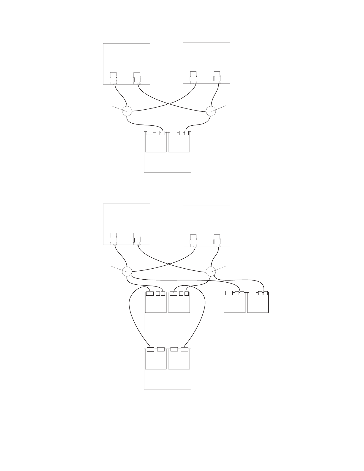
Redundant host and drive loops
This section provides examples of FAStT600 host Fibre Channel configurations,
including:
v Redundant host and drive loop Fibre Channel configurations in Figure 19 on
page 23
v Single SAN fabric zone configuration in Figure 20 on page 24
v Dual SAN fabric zone configuration, with an additional FAStT600 storage server
and an EXP expansion unit attached in Figure 21 on page 24
v Two clusters in Figure 22 on page 25
Note: These configurations have host and drive path failover protection and are
recommended for high availability.
22 IBM TotalStorage FAStT600 Fibre Channel Storage Server: Installation and User’s Guide
Page 53

Host system
with two host
adapters
Host system
with two host
adapters
Host system
with two host
adapters
Note: Node level
redundancy with
cluster software.
Switch
FAStT600 FAStT600
Host system
with two host
adapters
Host system
with two host
adapters
Switch
Figure 19. Redundant host and drive Fibre Channel loop configurations
FAStT600
Chapter 2. Installing and configuring the storage server 23
Page 54
Host system
with two host
adapters
Host system
with two host
adapters
Switch
Interswitch link
FAStT600
Switch
Figure 20. Example of a single SAN fabric zone configuration
Host system
with two host
adapters
Switch
Host system
with two host
adapters
Switch
Figure 21. Example of a dual SAN fabric zone configuration
24 IBM TotalStorage FAStT600 Fibre Channel Storage Server: Installation and User’s Guide
FAStT600 FAStT600
EXP700
(Expansion unit)
Page 55

Host system
with two host
adapters
Host system
with two host
adapters
Host system
with two host
adapters
Host system
with two host
adapters
Switch
Switch
Figure 22. Example of two clusters
Switch
FAStT600
Switch
Chapter 2. Installing and configuring the storage server 25
Page 56

Installing the storage subsystem configuration
Using the information gathered in the previous sections, install the host systems
and host adapters.
Notes:
1. See the documentation provided with your host adapters for installation
requirements and procedures.
2. Use the correct host adapter driver. For the latest supported host adapters and
drivers, go to the following Web site:
www.ibm.com/support/
Attach fiber-optic interface cables to each host adapter. You will connect the other
end of the cables to the controller later in the installation process. For more
information about handling fiber-optic cables, see “Installing fiber-optic cables” on
page 30.
Note: Do not install the storage-management software at this time, if it is not
already installed. Install the storage server completely before you install the
software because you cannot test the software installation until the hardware
is connected.
26 IBM TotalStorage FAStT600 Fibre Channel Storage Server: Installation and User’s Guide
Page 57

Chapter 3. Cabling the storage server
This chapter provides Fibre Channel and power cabling information for the storage
server.
After you attach the storage server power cables, use the instructions that are
provided in “Turning the storage server on and off” on page 37 for the initial startup
of the storage server.
Working with SFPs and fiber-optic cables
Each RAID controller has two host ports and one expansion port. An SFP is used to
connect each host port and expansion port to hosts and expansion units. The SFP
is inserted into the port, and then a fiber-optic cable is inserted into the SFP. The
other end of the fiber-optic cable connects to an external device. SFPs are laser
products.
Statement 3
CAUTION:
When laser products (such as CD-ROMs, DVD drives, fiber optic devices, or
transmitters) are installed, note the following:
v Do not remove the covers. Removing the covers of the laser product could result in
exposure to hazardous laser radiation. There are no serviceable parts inside the
device.
v Use of controls or adjustments or performance of procedures other than those
specified herein might result in hazardous radiation exposure.
Danger
Some laser products contain an embedded Class 3A or Class 3B laser diode. Note the
following.
Laser radiation when open. Do not stare into the beam, do not view directly with optical
instruments, and avoid direct exposure to the beam.
Handling fiber-optic cables
Before using fiber-optic cables, read the following precautions.
Attention: To avoid damage to the fiber-optic cables, follow these guidelines:
v Do not route the cable along a folding cable-management arm.
v When attaching to a device on slide rails, leave enough slack in the cable so that
it does not bend to a radius of less than 38 mm (1.5 in.) when extended or
become pinched when retracted.
v Route the cable away from places where it can be snagged by other devices in
the rack.
© Copyright IBM Corp. 2003 27
Page 58

v Do not overtighten the cable straps or bend the cables to a radius of less than 38
mm (1.5 in.).
v Do not put excess weight on the cable at the connection point. Be sure that the
cable is well supported.
Installing SFP modules
The FAStT600 Storage Server host ports require Small Form-Factor Pluggable
(SFP) Modules. SFP modules are used to convert electrical signals to optical
signals that are required for Fibre Channel transmission to and from RAID
controllers. The FAStT600 Storage Server supports two types of SFP modules; one
with a plastic latch and one with a wire latch. After you install the SFP modules, you
will use fiber-optic cables to connect the FAStT600 Storage Server to other Fibre
Channel devices.
Before you install SFP modules and fiber-optic cables, read the following
information:
v The SFP module housing has an integral guide key designed to prevent you from
inserting the SFP module improperly.
v Use minimal pressure when you insert the SFP module into a port. Forcing the
SFP module into a port could cause damage to the SFP module or the port.
v You can insert or remove the SFP module while the port is powered on.
v The operational loop performance is not affected when you install or remove an
SFP module.
v You must insert the SFP module into a port before you connect the fiber-optic
cable.
v You must remove the fiber-optic cable from the SFP module before you remove
the SFP module from the port. See “Removing SFP modules” on page 30 for
more information.
To install an SFP module, complete the following steps.
Statement 3:
CAUTION:
When laser products (such as CD-ROMs, DVD drives, fiber-optic devices, or
transmitters) are installed, note the following:
v Do not remove the covers. Removing the covers of the laser product could
result in exposure to hazardous laser radiation. There are no serviceable
parts inside the device.
v Use of controls or adjustments or performance of procedures other than
those specified herein might result in hazardous radiation exposure.
28 IBM TotalStorage FAStT600 Fibre Channel Storage Server: Installation and User’s Guide
Page 59

DANGER
Some laser products contain an embedded Class 3A or Class 3B laser
diode. Note the following.
Laser radiation when open. Do not stare into the beam, do not view directly
with optical instruments, and avoid direct exposure to the beam.
Attention: When you handle static-sensitive devices, take precautions to avoid
damage from static electricity. For details about handling static-sensitive devices,
see “Handling static-sensitive devices” on page 3.
1. Remove the SFP module from its static-protective package.
2. Remove the protective cap from the SFP module, as shown in Figure 23. Save
the protective cap for future use.
Plastic tab
Protective cap
SFP module
Figure 23. Small Form-Factor Pluggable (SFP) Module
3. Remove the protective cap from the host port. Save the protective cap for future
use.
4. Insert the SFP module into the host port until it clicks into place. See Figure 24.
SFP module
Raid controller
Fiber-optic
cable
Figure 24. Installing an SFP module into the host port
5. Connect a Fibre Channel cable.
Chapter 3. Cabling the storage server 29
Page 60
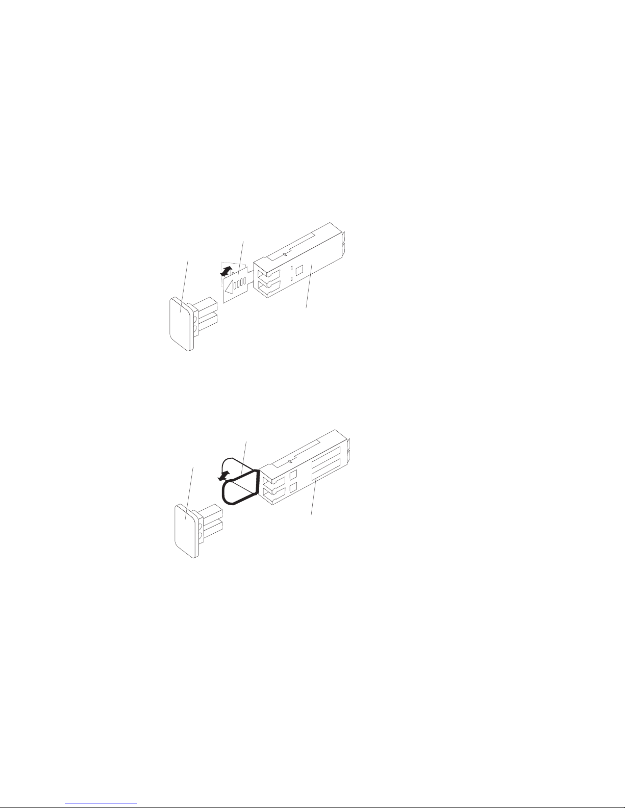
Removing SFP modules
To remove the SFP module from the host port, perform the following steps.
Attention: To avoid damage to the cable or the SFP module, make sure you
unplug the LC-LC Fibre Channel cable before you remove the SFP module.
1. Remove the LC-LC Fibre Channel cable from the SFP module. For more
information, see “Handling fiber-optic cables” on page 27.
2. Unlock the SFP module latch:
v For SFP modules containing plastic tabs, unlock the SFP module latch by
pulling the plastic tab outward 10°, as shown in Figure 25.
Protective cap
o
10
Figure 25. Unlocking the SFP module latch - plastic variety
Plastic tab
SFP module
v For SFP modules containing wire tabs, unlock the SFP module latch by
pulling the wire latch outward 90°, as shown in Figure 26.
Wire tab
Protective cap
o
90
SFP module
Figure 26. Unlocking the SFP module latch - wire variety
3. With the SFP latch in the unlocked position, extract the SFP module.
v For SFP modules containing plastic tabs, slide the SFP module out of the
port.
v For SFP modules containing wire tabs, grasp the wire latch and pull the SFP
module out of the minihub port.
4. Replace the protective cap on the SFP module.
5. Place the SFP module into a static-protective package.
6. Replace the protective cap on the port.
Installing fiber-optic cables
To connect the fiber-optic cables, perform the following steps.
30 IBM TotalStorage FAStT600 Fibre Channel Storage Server: Installation and User’s Guide
Page 61
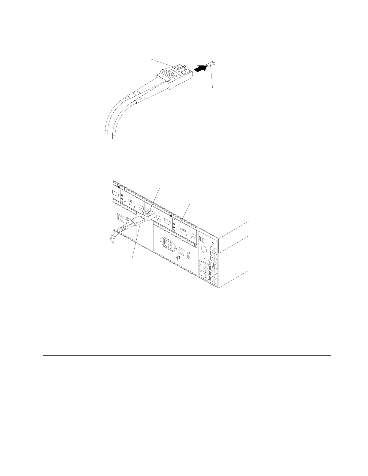
1. Remove the protective cap from the fiber-optic cable. See Figure 27.
Fiber-optic
cable
Protective cap
Figure 27. Removing caps from fiber-optic cables
2. Connect the fiber-optic cable to the installed SFP, as shown in Figure 28.
SFP module
Raid controller
Fiber-optic
cable
Figure 28. Connecting cables to the installed SFP
3. Check the LEDs on the RAID controller. When the RAID controller is operating
properly, the amber Fault LED is off. For information about the status of the
RAID controller LEDs, see Table 11 on page 44.
4. To remove the fiber-optic cables, gently pull the fiber-optic cable from the SFP;
then replace the protective caps.
Connecting hosts to the RAID controllers
To connect a host adapter to the RAID controller, perform the following steps.
1. Install a SFP in a host port on the RAID controller.
2. Connect the host-system cables to the RAID controller or to switches. Figure 29
on page 32 shows the location on the RAID controllers where the host-system
cables connect.
Chapter 3. Cabling the storage server 31
Page 62

Controller A
Controller B
Host A: Host Adapter 1
(or from managed hub
or switch)
Figure 29. Location of host cables
For examples of redundant, partially-redundant, and non-redundant host and drive
loop configurations, see “Fibre Channel loop configurations” on page 22.
Connecting secondary interface cables
Use the Ethernet interface ports on the back of the storage server to connect the
controllers for direct management of the storage subsystems. Connect a pair of
Ethernet cables from the storage-management station to the Ethernet ports for
Controller A (located on the left) and Controller B (located on the right) on the back
of the storage server. Figure 30 shows the location of the ports.
Controller A
Ethernet port
Controller A
Serial port
Host A: Host Adapter 2
(or from managed hub
or switch)
Controller B
Ethernet port
Controller B
Serial port
Figure 30. Ethernet and serial port locations
Note: The serial interface ports are intended to be used by service technicians to
perform diagnostic operations on the storage server.
Power cabling
|
|
|
|
|
|
|
The storage server uses two standard power cords. You can connect the power
cords to a primary power unit inside the rack, such as a properly grounded ac
distribution unit, or to an external source, such as a properly grounded electrical
outlet.
If you have not already done so, attach the power cords, using the following
illustration for the location of the component parts.
|
32 IBM TotalStorage FAStT600 Fibre Channel Storage Server: Installation and User’s Guide
Page 63

|
Lever
-
AC power
switch
AC power
connector
|
|
Figure 31. Power cord locations
Strain-relief
clamp
|
|
|
|
|
|
|
|
|
|
|
|
|
|
1. Wrap the strain-relief clamp around the power cord approximately 20 cm (8 in.)
from the power supply connection end.
2. Attach the power-supply nut, and tighten it securely.
3. Connect the power cord to the power supply.
4. Plug the power cord into a properly grounded electrical outlet.
Note: To maintain power redundancy, plug the FAStT600 Storage Server’s right
and the left power supplies into two independent external power circuits
through ac distribution units inside a rack cabinet or directly into external
receptacles. Similarly, the right and left power supplies of the FAStT drive
enclosures attached to the FAStT600 Storage Server should be plugged
into the same two independent external power circuits as the FAStT600
Storage Server. See Figure 32 on page 34 for an example of redundant
power cabling.
|
Chapter 3. Cabling the storage server 33
Page 64
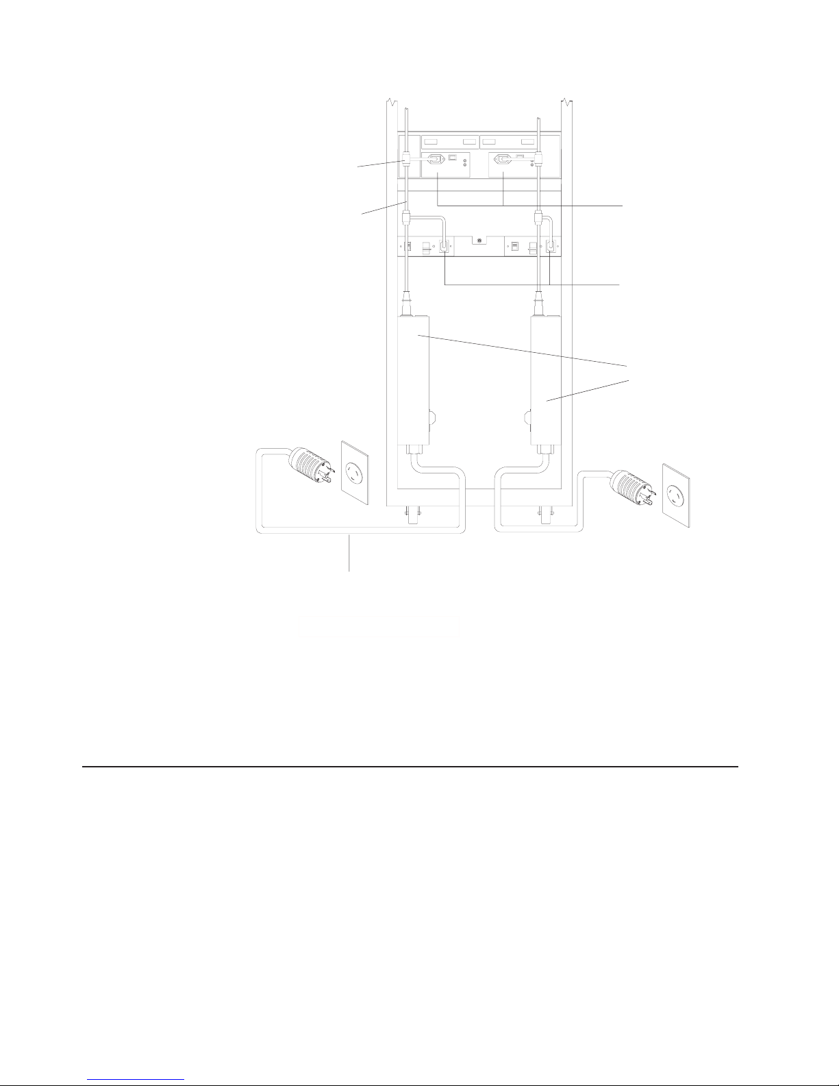
|
Ladder cable connector
Drive expansion unit
Ladder cable
power supplies
Controller power supplies
AC distribution units
AC distribution unit
power cord
|
|
|
|
|
|
|
Figure 32. Redundant AC power connections to controllers and drive expansion units
For details about power requirements, see “Operating specifications” on
page 8.
5. Go to “Turning the storage server on and off” on page 37 for the initial startup of
the storage server.
Installing the storage-management software
Install the storage-management software by using the procedures in the software
Installation and Support Guide for your operating system. Use that document and
the online help to configure the logical drives, partitions, and so on for the RAID
controllers. Use your operating system documentation to make the new logical
drives accessible to the operating system.
Note: Make sure that you start the storage-management software to continuously
monitor the status of the storage server. For information about the
importance of this information, see “Monitoring status through software” on
page 41.
34 IBM TotalStorage FAStT600 Fibre Channel Storage Server: Installation and User’s Guide
Page 65

Connecting additional expansion units
After you install the storage server, you can connect additional expansion units. You
can do this at any time after you install the storage server, even while it is turned on
and processing data. You can even install one expansion unit now and an additional
expansion unit later.
Note: You must purchase an option to connect additional drive expansion
enclosures to the FAStT600 storage server. Contact your IBM resellers or
marketing representatives for more information.
Attention: You can add only new expansion units to the storage server. This
means that there must be no existing configuration information on the expansion
unit that you want to install. If the expansion unit that you want to install currently
contains logical drives or configured hot spares, and you want them to be part of
the FAStT600 storage server, you must contact IBM for information. Improper drive
migration might cause loss of configuration and other storage server problems.
To connect an additional expansion unit, perform the following steps.
1. Follow the instructions in your expansion unit installation manual to set up and
mount the new expansion unit.
2. Use the following procedure and illustration to connect a single expansion unit
to the storage server:
a. Use a fiber-optic cable to connect to the FC-Expansion Units port on the left
RAID controller in the storage server to the In port on the left ESM board of
the expansion unit.
b. Use a second fiber-optic cable to connect the FC-Expansion Units port on
the right RAID controller in the storage server to the Out port on the right
ESM board of the expansion unit.
c. Ensure that the enclosure ID switch is set to a value different from one set
for the FAStT600 server and other drive expansion enclosures in the loop.
Also, ensure that the link speeds of the expansion units are set to 2 Gb.
Left ESM board Right ESM board
In port
Figure 33. Adding an expansion unit
Out port
New expansion unit
Storage server with
two RAID controllers
3. Remove the blank filler trays and insert drive trays. Connect power to the
storage server, and then connect power to the drive expansion enclosures. After
the enclosures are powered-on, the storage server locates the new drives.
4. Use the storage-management software to check the status of the new drives,
correct any errors found, and configure the new drives.
Chapter 3. Cabling the storage server 35
Page 66

Use the following procedure and illustration to connect a second expansion unit to
the storage server after previously adding the first expansion unit:
1. Ensure that the enclosure ID switch is set to a value different from one set for
the FAStT600 server and other drive expansion enclosures in the loop. Also,
ensure that the link speeds of the expansion units are set to 2 Gb.
2. Disconnect cable 1 from its current connection and connect it to the In port on
the left ESM board on the new expansion unit.
3. Connect cable 2to the In port you disconnected in step 1 and the Out port on
the left ESM board on the new expansion unit.
4. Connect a third cable 3 to the In port on the right ESM board on the first
expansion unit and the Out port on the right ESM board on the new expansion
unit.
Left ESM board Right ESM board
In port
Out port Out port
New expansion unit
New cables
First expansion unit
Storage server
with two RAID controllers
Figure 34. Adding a second expansion unit
5. Remove the blank filler trays and insert drive trays. Connect power to the
storage server, and then connect power to the drive expansion enclosures. After
the enclosures are powered-on, the storage server locates the new drives.
6. Use the storage-management software to check the status of the new drives,
correct any errors found, and configure the new drives.
For more detailed information about how to cable the storage server and expansion
units, see the IBM FAStT600 Fibre Channel Cabling Instructions that come with the
storage server.
36 IBM TotalStorage FAStT600 Fibre Channel Storage Server: Installation and User’s Guide
Page 67

Chapter 4. Operating the storage server
|
|
|
|
|
|
|
|
|
|
|
|
|
|
|
|
|
|
|
|
|
|
|
|
|
|
|
|
|
|
|
|
|
|
|
|
|
|
To ensure optimal operation of your system, always follow these best practices
guidelines:
v Back up the data on your storage drives periodically.
v To maintain power redundancy, plug the FAStT600 Storage Server’s right and the
left power supplies into two independent external power circuits through ac
distribution units inside a rack cabinet or directly into external receptacles.
Similarly, the right and left power supplies of the FAStT drive enclosures attached
to the FAStT600 Storage Server should be plugged into the same two
independent external power circuits as the FAStT600 Storage Server. This
ensures that the FAStT600 Storage Server and all its attached drive enclosures
will have power if only one power circuit is available. In addition, having all the
right or all the left power supplies plug into the same power circuit will enable the
components in the storage subsystem to power on simultaneously during an
unattended restoration of power. See Figure 32 on page 34 for an example of
redundant power connections.
v Before any planned system shutdown or after any system changes (additions,
removals, or modifications), save controller subsystem profiles as explained in
the Storage Manager guide for your operating system.
v Ensure that your system is in an optimal state before shutting down. Never turn
the power off if any fault light is lit; be sure to resolve any error conditions before
you shut down the system.
v During any maintenance or attended power-up procedure, carefully follow the
power-up sequence listed in “Turning on the storage server” on page 38. Each
component of the subsystem should be checked that it is powered-on in the
proper order during this entire power-up procedure to ensure the controller will be
able to optimally access all of your storage subsystems.
v The storage subsystem supports simultaneous power-up to the system
components; however, you should always follow the power-up sequence listed in
“Turning on the storage server” on page 38 during any attended power-up
procedure.
v A storage system in an optimal state should recover automatically from an
unexpected shutdown and unattended simultaneous restoration of power to
system components. After power is restored, call IBM support if any of the
following conditions occur:
– The storage subsystem logical drives and arrays are not displayed in the
Storage Manager graphical user interface (GUI).
– The storage subsystem logical drives and arrays do not come online.
– The storage subsystem logical drives and arrays seem to be degraded.
Turning the storage server on and off
This section contains instructions for turning the storage server on and off under
normal and emergency situations.
If you are turning on the storage server after an emergency shutdown or power
outage, see “Restoring power after an emergency shutdown” on page 41.
© Copyright IBM Corp. 2003 37
Page 68

Turning on the storage server
|
|
|
|
|
|
|
|
|
Important: You must turn on the drive enclosures and verify that the drive
enclosures’ FC connections are optimal by checking the indicator lights
before you turn on the FAStT600 Storage Server. The controllers might
not recognize the correct configuration if the hard disk drives are
powered up after the FAStT600 Storage Server. For instructions on
powering up the drive enclosures, refer to the drive enclosure
documentation.
Note: Always wait at least 30 seconds between the time you turn off a power
switch and the time you turn on the power again.
Use this procedure to turn on the power for the initial startup of the storage server:
1. Verify that:
a. All communication and power cables are plugged into the back of the
storage server and a properly grounded ac electrical outlet
b. All hard disk drives are locked securely in place. For more information, see
“Installing hot-swap drives” on page 50.
Note: At least one drive must be present before you start the FAStT600.
Attention: If you are restarting the system after a normal shutdown, wait at
least 10 seconds before you turn on the power by using the power-on sequence
in step 2.
2. Check the system documentation for the hardware devices that you intend to
power up, and then determine the proper startup sequence. Use the following
power-on sequence, where applicable:
a. Turn on the power to the supporting devices (for example, Ethernet switches
and management stations) before the storage server.
Attention: If you will be directly managing the storage array, you must set
up the Dynamic Host Configuration Protocol (DHCP) or BOOT-P server
before turning on the power. Setting up the server allows the controllers to
obtain the corresponding IP address when you turn on the power to the
array module. For more information, see the software installation guide for
your operating system.
b. You must turn on the expansion units before the storage server. The
controllers might not recognize the correct configuration if the drives are
powered up after the storage server. For instructions on powering up the
expansion units, see the expansion-unit documentation.
c. Turn on the power to the storage server; then restart or turn on the power to
the host.
Note: Depending on your operating system, you might not have to restart
3. Turn on the power to each device, based on the power-on sequence in step 2.
To turn on power to the storage server, turn on the power-supply switches on
the back of the storage server. You must turn on both power-supply switches to
take advantage of the redundant power supplies.
4. Use the storage-management software and the Fault LEDs to check the overall
status of the storage server and its components. All LEDs should be green on
the front of the storage server. If they are not, use the storage-management
software to diagnose the problem (see “Monitoring status through software” on
page 41).
38 IBM TotalStorage FAStT600 Fibre Channel Storage Server: Installation and User’s Guide
the host. For more information, see the software installation guide for
your operating system.
Page 69

Note: The green Drive active LED and amber Drive fault LED below the drive
CRUs might flash intermittently as the drives spin-up. Wait until the
storage server is finished powering up before checking the LEDs on the
front of the storage server. For more information, see “Checking the
LEDs” on page 42.
Turning off the storage server
|
|
|
|
|
|
|
|
Attention: Except in an emergency, never turn off the power if any storage server
Fault LEDs are on. Correct the fault before you turn off the power. Use the
storage-management software and the Fault LEDs to check the overall status of the
storage server and its components. All LEDs should be green on the front of the
storage server. If they are not, use the storage-management software to diagnose
the problem (see “Monitoring status through software” on page 41). This ensures
that the storage server will power up correctly later. For more information, see
“Troubleshooting” on page 74.
The storage server is designed to run continuously, 24 hours a day. After you turn
on the storage server, do not turn it off. Turn off the power only when:
v Instructions in a hardware or software procedure require you to turn off the
power.
v A service technician tells you to turn off the power.
v A power outage or emergency situation occurs (see “Performing an emergency
shutdown” on page 41).
Statement 5
CAUTION:
The power control button on the device and the power supply do not turn off the
electrical current supplied to the device. The device also might have more than one
power cord. To remove all electrical current from the device, ensure that all power
cords are disconnected from the power source.
2
1
Use this procedure to turn off the power:
1. Before proceeding, use the storage-management software to determine the
status of the system components and special instructions. The operating system
software might require you to perform other procedures before you turn off the
power.
2. Use the storage-management software to check the status of the storage
server. Correct problems that are reported before you turn off the power.
3. Perform the following steps:
a. Stop all I/O activity to the storage server and attached expansion units.
Make sure that:
v All of the green Drive active LEDs on the front of the storage server (and
on all attached expansion units) are not flashing.
Chapter 4. Operating the storage server 39
Page 70

v The green Cache active LEDs on the back of the storage server are off.
b. If applicable, use the operating system software to disconnect the storage
server logical drives from the host before the storage server is powered off.
Attention: To turn off all power to the storage server, you must turn off both
power-supply switches and disconnect both power cords. Use the procedure in
step 4 for the proper shutdown sequence.
4. Turn off the power to each device based on the following shutdown sequence:
a. Turn off power to the host before the storage server. If the host must stay
powered on to support an existing network, see the operating system
documentation for information about disconnecting the storage server logical
drives from the host before the storage server is powered off.
b. Turn off power to the storage server before you turn off power to the
expansion units. Turn off both power supply switches on the back of the
storage server.
c. Turn off power to other supporting devices (for example, management
stations, fibre-channel switches, or Ethernet switches).
Note: You do not need to perform this step if you are servicing only the
storage server.
5. After you perform the necessary maintenance procedures, turn on the power
using the procedure in “Turning on the storage server” on page 38.
Restoring power after an unexpected shutdown
The storage server might shut down unexpectedly under any of the following
conditions:
Attention: There might be data loss in each of the following cases:
v The internal temperature of the storage server exceeds the maximum operating
temperature (an over-temperature condition).
If both fan CRUs fail or are unable to maintain an internal temperature below
70°C (158°F), one or both of the power supplies in the storage server will shut
down. If both power supplies shut down, the unit is inoperable.
The storage-management software warns you if the temperature of the unit is
rising, before it has risen sufficiently to shut down the power supplies. The first
warning comes when the storage server internal temperature exceeds 45°C
(113°F). The storage server shuts down if the temperature rises to 70°C (158°F).
v There is a general power failure or a loss of power to the unit.
v You are forced to shut down the storage server without performing the normal
shutdown procedures (listed in “Turning off the storage server” on page 39)
because of an emergency situation.
Attention: To avoid damage to the hardware, take special care when restarting
the system after an unexpected shutdown.
|
|
|
If the storage server shuts down unexpectedly, go to “Restoring power after an
over-temperature shutdown” on page 41. Otherwise, go to “Restoring power after an
emergency shutdown” on page 41.
|
|
|
Note: Unattended restoration of power is supported; however, if power restoration
is attended, you should follow the best practices guidelines and the power
restoration sequence in “Turning on the storage server” on page 38.
40 IBM TotalStorage FAStT600 Fibre Channel Storage Server: Installation and User’s Guide
Page 71

Performing an emergency shutdown
Attention: Emergency situations might include fire, flood, extreme weather
conditions, or other hazardous circumstances. If a power outage or emergency
situation occurs, always turn off all power switches on all computing equipment.
This will help safeguard your equipment from potential damage due to electrical
surges when power is restored. If the storage server loses power unexpectedly, it
might be due to a hardware failure in the power system or midplane (see
“Troubleshooting” on page 74).
Use this procedure to shut down the storage server during an emergency:
1. If you have time, stop all I/O activity to the storage server by shutting down the
host or disconnecting the storage server logical drives through the host.
2. Check the LEDs (front and back). Make note of any Fault LEDs that are on so
you can correct the problem when you turn on the power again.
3. Turn off all power-supply switches; then unplug the power cords from the
storage server.
Restoring power after an emergency shutdown
Use this procedure to restart the storage server if you turned off the power-supply
switches during an emergency shutdown, or if a power failure or a power outage
occurred:
1. After the emergency situation is over or power is restored, check the storage
server for damage. If there is no visible damage, continue with step 2;
otherwise, have your system serviced.
2. After you have checked for damage, ensure that the power-supply switches are
off; then plug in the storage-server power cords.
3. Complete step 2 on page 38 to determine the proper power-on sequence for
your system.
4. Complete steps 3 and 4 on page 38 to turn on power to the devices in your
system and to check the status of the storage server.
Restoring power after an over-temperature shutdown
Use this procedure to restart the storage server after an unexpected shutdown due
to an over-temperature condition:
1. Make sure that the power-supply switches on the back of the storage server are
turned off.
2. Do whatever is necessary to cool the unit (replace the fans, use external fans to
cool the room, and so on).
3. Check all components and cables for visible damage. Do not start the storage
server if you find evidence of damage.
4. Complete step 2 on page 38 to determine the proper power-on sequence for
your system.
5. When the internal temperature of the storage server is below 35°C (95°F),
complete steps 3 and 4 on page 38 to turn on power to the devices in your
system and to check the status of the storage server.
Monitoring status through software
Use the storage-management software to monitor the status of the storage server.
Run the software constantly, and check it frequently.
Chapter 4. Operating the storage server 41
Page 72

The storage-management software provides the best way to diagnose and repair
storage-server failures. The software can help you:
v Determine the nature of the failure
v Locate the failed component
v Determine the recovery procedures to repair the failure
Although the storage server has fault LEDs, these lights do not necessarily indicate
which component has failed or needs to be replaced, or which type of recovery
procedure you must perform. In some cases (such as loss of redundancy in various
components), the fault LED does not turn on. Only the storage-management
software can detect the failure.
®
For example, the recovery procedure for a Predictive Failure Analysis
(PFA) flag
(impending drive failure) on a drive varies depending on the drive status (hot spare,
unassigned, RAID level, current logical drive status, and so on). Depending on the
circumstances, a PFA flag on a drive can indicate a high risk of data loss (if the
drive is in a RAID 0 volume) or a minimal risk (if the drive is unassigned). Only the
storage-management software can identify the risk level and provide the necessary
recovery procedures.
Note: For PFA flags, the General-system-error LED and Drive fault LEDs do not
turn on, so checking the LEDs will not notify you of the failure, even if the
risk of data loss is high.
Recovering from a storage-server failure might require you to perform procedures
other than replacing the component (such as backing up the logical drive or failing a
drive before removing it). The storage-management software gives these
procedures.
Attention: Not following the software-recovery procedures can result in data loss.
Checking the LEDs
The LEDs display the status of the storage server and components. Green LEDs
indicate a normal operating status; amber LEDs indicate a possible failure.
It is important to check all the LEDs on the front and back of the storage server
when you turn on the power. In addition to checking for faults, you can use the
LEDs on the front of the storage server to determine if the drives are responding to
I/O transmissions from the host.
For information about the LEDs on the front of the storage server, see:
v Figure 35 on page 43
v Table 10 on page 43
For information about the LEDs on the back of the storage server, see:
v Figure 37 on page 45
v Table 11 on page 44
v Table 12 on page 46
42 IBM TotalStorage FAStT600 Fibre Channel Storage Server: Installation and User’s Guide
Page 73

General-system-
Power-on LED
error LED
Locator LED
Drive activity LED
Drive fault LED
Figure 35. Storage server LEDs (front)
Table 10. Storage server LEDs (front)
LED Color Operating states
Drive active Green
v On - Normal operation.
1
v Flashing - The drive is reading or writing data.
v Flashing every 5 seconds - The drive has not
spun up or the drive is bad.
v Off - One of the following situations has occurred:
– The storage server has no power.
– The drive is not properly seated in the storage
server.
Drive fault Amber
v Off - Normal operation.
v Flashing - The storage-management software is
locating a drive, logical drive, or storage
subsystem.
v On - The drive has failed, or a user failed the drive.
Power Green
v On - Normal operation.
v Off - One of the following situations has occurred:
– The storage server has no power.
– Both power supplies have failed.
– There is an over-temperature condition.
General system
error
Locator Blue
Amber
v Off - Normal operation.
v On - A storage server component has failed
v On - When on, this blue LED indicates that the
user had initiated a storage-management software
function to locate the storage server.
v Off - Normal operation.
1
Always use the storage-management software to identify the failure.
2
Not all component failures turn on this LED. For more information, see “Monitoring status
through software” on page 41.
2
.
Chapter 4. Operating the storage server 43
Page 74

2Gbps
Expansion link indicator
Host 1
Host 1
indicator
2Gb/s
Host 2
Host 2
indicator
2Gb/s
10BT 100BT
10BT
100BT
10101
+
Battery
charging
Cache
active
Controller
Figure 36. RAID controller LEDs
Table 11. RAID controller LEDs
Icon LED Color Operating states
Fault Amber
v Off - Normal operation.
v On - One of the following situations has
occurred:
– The RAID controller has failed.
– The RAID controller was placed offline.
Host loop Green
v On - Normal operation.
v Off - One of the following situations has
occurred:
– The host loop is down, not turned on,
or not connected.
– A SFP has failed, or the host port is not
occupied.
– The RAID controller circuitry has failed,
or the RAID controller has no power.
Cache active Green
v On - There is data in the RAID controller
cache.
v Off - One of the following situations has
occurred:
– There is no data in cache.
– There are no cache options selected for
this array.
– The cache memory has failed, or the
battery has failed.
+
Battery Green
v On - Normal operation.
v Flashing - The battery is recharging or
performing a self-test.
v Off - The battery or battery charger has
failed.
fault
1
Expansion
Expansion
by-pass
44 IBM TotalStorage FAStT600 Fibre Channel Storage Server: Installation and User’s Guide
Page 75

Table 11. RAID controller LEDs (continued)
Icon LED Color Operating states
Expansion
port bypass
Amber
v Off - Normal operation.
v On - One of the following situations has
occurred:
– An SFP module is inserted in the drive
loop port and the fibre-channel cable is
not attached to it.
– The fibre-channel cable is not attached
to an expansion unit.
– The attached expansion unit is not
turned on.
– An SFP has failed, a fibre-channel
cable has failed, or an SFP has failed
on the attached expansion unit.
Expansion
loop
Green
v On - Normal operation.
v Off - The RAID controller circuitry has
failed, or the RAID controller has no
power.
2Gbps 2Gbps Green
v On - Normal operation (host connection is
at 2Gbps).
v Off - Host connection is at 1Gbps (which
is not supported for controller firmware
05.33.xx.xx.
10BT 10BT Green
v If the Ethernet connection is 10BASE-T:
The 10BT LED is on, 100BT LED flashes
faintly.
v If the Ethernet connection is
100BT 100BT
100BASE-T: 10BT LED is off, 100BT LED
is on.
v If there is no Ethernet connection - Both
LEDs are off.
1
Always use the storage-management software to identify the failure.
1
Fan fault LED
Figure 37. Fan and power supply LEDs
Power LED
Power supply
fault LEDs
Fan fault LED
Power LED
Chapter 4. Operating the storage server 45
Page 76

Table 12. Fan LED
LED Color Operating states
Fault Amber
1
Always use the storage-management software to identify the failure.
Table 13. Power supply LEDs
LED Color Operating states
Fault Amber
Power Green
1
Always use the storage-management software to identify the failure.
v Off - Normal operation.
v On - The fan CRU has failed.
v Off - Normal operation.
v On - One of the following situations has occurred:
– The power supply has failed.
– An over-temperature condition has occurred.
v On - Normal operation.
v Off - One of the following situations has occurred:
– The power supply is disconnected.
– The power supply is seated incorrectly.
– The storage server has no power.
– The power supply is turned off.
1
1
Cache memory and RAID controller battery
Each RAID controller contains 128 MB of cache data. It also contains a
rechargeable battery that maintains data in the cache in the event of a power
failure. The following sections describe these features and their associated LEDs.
Cache memory
Cache memory is memory on the RAID controller that is used for intermediate
storage of read and write data. Using cache memory can increase system
performance. The data for a read operation from the host might be in the cache
memory from a previous operation (thus eliminating the need to access the drive
itself), and a write operation is completed when it is written to the cache, rather than
to the drives.
See the storage-management software documentation for information on setting
cache memory options.
The RAID controller has a Cache active LED that displays the current status of the
cache. The LED is on if there is data in the cache, and it is off if there is no data in
the cache.
If caching is enabled and the Cache active LED never comes on during I/O activity,
it indicates that the cache memory has failed or the battery has failed (the green
Battery LED will be off).
Note: Always use the storage-management software to check your cache memory
settings before assuming a hardware failure.
46 IBM TotalStorage FAStT600 Fibre Channel Storage Server: Installation and User’s Guide
Page 77

Figure 38 shows the location of the Cache active LED on the front of the RAID
controller.
Figure 38. Cache active LED
RAID controller cache battery
Each RAID controller contains a sealed, rechargeable 4-volt lead-acid battery. This
battery provides cache backup for up to five days in the event of a power loss.
The service life of the battery is three years, after which time the battery must be
replaced. See the storage-management software for information on how to view and
set the battery expiration date.
Cache
active
LED
Each RAID controller has a green Battery LED on the back that indicates the
battery status, as follows:
v The LED is on and remains steady when the battery is fully charged.
v The LED flashes when the battery is charging or performing a self-test.
v The LED is off if the battery or the battery charger has failed.
The battery performs a self-test at startup and every 25 hours thereafter (during
which time the Battery LED flashes). If necessary, the battery begins recharging at
that time. If the battery fails the self-test, the Battery LED turns off, indicating a
battery fault.
Data caching starts after the battery completes the startup tests.
Figure 39 shows the location of the Battery LED on the front of the RAID controller.
Figure 39. Battery LED
Battery
LED
Chapter 4. Operating the storage server 47
Page 78

48 IBM TotalStorage FAStT600 Fibre Channel Storage Server: Installation and User’s Guide
Page 79

Chapter 5. Installing and replacing components
This chapter provides instructions to help you install or remove customer
replaceable units (CRUs), such as hot-swap drives, fans, RAID controllers, and
power supplies.
For more field-replaceable unit (FRU) and Option part number information, see the
following Web site:
www.ibm.com/storage/techsup.htm
Handling static-sensitive devices
Attention: Static electricity can damage electronic devices and your system. To
avoid damage, keep static-sensitive devices in their static-protective packages until
you are ready to install them.
To reduce the possibility of electrostatic discharge, observe the following
precautions:
v Limit your movement. Movement can cause static electricity to build up around
you.
v Handle the device carefully, holding it by its edges or its frame.
v Do not touch solder joints, pins, or exposed printed circuitry.
v Do not leave the device where others can handle and possibly damage the
device.
v While the device is still in its static-protective package, touch it to an unpainted
metal part of the storage server for at least two seconds. This drains static
electricity from the package and from your body.
v Remove the device from its package and install it directly into your storage
server without setting it down. If it is necessary to set the device down, place it in
its static-protective package. Do not place the device on your storage server
cover or any metal surface.
v Take additional care when handling devices during cold weather because heating
reduces indoor humidity and increases static electricity.
Working with hot-swap drives
Drives are devices that the system uses to store and retrieve data. This section
explains how you can increase the storage-server capacity by adding more drives
or replacing existing drives with ones containing a larger capacity.
Figure 40 on page 50 shows the location of the hot-swap drive bays that are
accessible from the front of the storage server. To maintain proper cooling within the
storage server, always keep a filler panel in each drive bay that does not contain a
drive CRU.
© Copyright IBM Corp. 2003 49
Page 80

Hot-swap
drive CRU
Figure 40. Location of hot-swap drives
Attention: Never hot-swap a drive CRU when its green Activity LED is flashing.
Hot-swap a drive CRU only when its amber Fault LED is completely on and not
flashing or when the drive is inactive with the green Activity LED on and not
flashing.
Before you install or remove drive CRUs, review the following information:
Filler panels
Storage servers without a full set of drives (14) contain filler panels in the
unused drive bays. Before installing new drives, you must remove the filler
panels. Save the filler panels for future use. Each of the 14 bays must
always contain either a filler panel or a drive CRU.
Drive CRUs
The RAID controller supports up to 14 (half-high or slim) 40-pin
fibre-channel hard disk drives. These drives come preinstalled in drive trays.
This drive-and-tray assembly is called a drive CRU. You can install the drive
CRUs in the 14 drive bays on the front of the storage server.
Drive LEDs
Each drive CRU has two LEDs, which indicate the status for that particular
drive. For information about the drive LED operating states and
descriptions, see Figure 35 on page 43 and Table 10 on page 43.
Fibre-channel loop IDs
When you install a drive CRU in the storage server, the drive CRU
connects into a printed circuit board called the midplane. The midplane
automatically sets the fibre-channel loop ID to the default value 00.
Hot-swap hardware
The storage server contains hardware that you can use to replace a failed
hard disk drive without turning off the storage server. Therefore, you can
continue operating the system while a hard disk drive is removed or
installed. These drives are known as hot-swap drives.
Slim drives
You can install slim, hot-swap drive CRUs.
Installing hot-swap drives
Before you begin, take the following precautions:
v Read the safety and handling guidelines that are provided in “Safety” on page iii
and “Handling static-sensitive devices” on page 49.
v Ensure that the current system configuration is working properly.
v Back up all important data before you make changes to storage devices, such as
hard disk drives.
50 IBM TotalStorage FAStT600 Fibre Channel Storage Server: Installation and User’s Guide
Page 81

Use the following procedure to install hot-swap drives in the storage server. You can
install additional drives while the storage server is powered up and running.
Note: If you are replacing a drive, see “Replacing hot-swap drives” on page 52.
1. Read the instructions that come with the drive CRU.
2. Check for Fault LEDs. If any amber LEDs are lit, see “Checking the LEDs” on
page 42 and “Troubleshooting” on page 74.
3. Determine the bay into which you want to install the drive.
4. Install the drive CRU:
Note: The hard disk drive comes with a tray already attached. Do not attempt
to detach the drive 4 from the tray 3. See Figure 41.
Figure 41. Releasing the drive latch
a. Release the blue latch 1 on the drive CRU by pressing on the inside of
the bottom of the tray handle. See Figure 41.
b. Pull the handle 2 on the tray out into the open position.
c. Slide the drive CRU into the empty bay until the tray handle 2 touches the
storage-server bezel.
d. Push the tray handle 2 down into the closed (latched) position.
5. Check the drive LEDs.
a. When a drive is ready for use, the green Activity LED is continuously on and
the amber Drive fault LED is off.
b. If the amber Drive fault LED is completely on and not flashing, remove the
drive from the unit and wait 10 seconds; then reinstall the drive.
6. Use the storage-management software to configure the drive.
7. Update the information in “Records”, on page 77.
Chapter 5. Installing and replacing components 51
Page 82

Replacing hot-swap drives
Drive problems include any malfunctions that delay, interrupt, or prevent successful
I/O activity between the hosts and the hard disk drives. This includes transmission
problems between the host controllers, the RAID controllers, and the drives. This
section explains how to replace a failed drive.
Attention: Failure to replace the drives in their correct bays might result in loss of
data. If you are replacing a drive that is part of a RAID level 1 or RAID level 5
logical drive, ensure that you install the replacement drive in the correct bay.
Use the following procedure to replace host-swap drives:
1. Check the hardware and software documentation that is provided with the
system to see if there are restrictions regarding hard disk drive configurations.
Some system fibre-channel configurations might not allow mixing different drive
capacities or types within an array.
2. Check the storage-management software for recovery procedures for a drive
that has failed. Follow the steps in the software procedure before you continue
with this procedure.
3. Determine the location of the drive that you want to remove.
Attention: Never hot-swap a drive CRU when its green Activity LED is
flashing. Hot-swap a drive CRU only when its amber Drive fault LED is on and
not flashing or when the drive is inactive with the green Activity LED on and not
flashing.
4. Remove the drive CRU.
a. Press on the inside of the bottom of the tray handle to release the blue latch
1. See Figure 42.
b. Pull the handle 2 on the tray 3 out into the open position.
c. Lift the drive CRU partially out of the bay.
d. To avoid possible damage to the drive 4, wait at least 20 seconds before
you fully remove the drive CRU from the storage server to allow for the drive
to spin down.
Figure 42. Drive latch on a hot-swap drive
e. Verify that there is proper identification (such as a label) on the drive CRU,
and then slide it completely out of the storage server.
52 IBM TotalStorage FAStT600 Fibre Channel Storage Server: Installation and User’s Guide
Page 83

5. Install the new drive CRU.
a. Gently push the drive CRU into the empty bay until the tray handle 2
touches the storage-server bezel.
b. Push the tray handle 2 down into the closed (latched) position.
6. Check the drive LEDs.
a. When a drive is ready for use, the green Activity LED is on, and the amber
Drive fault LED is off.
b. If the amber Drive fault LED is on and not flashing, remove the drive from
the unit and wait 10 seconds; then reinstall the drive.
7. Return to normal operation.
Upgrading drives
You can upgrade drives in the following two ways:
v By adding drives to empty slots in the storage server (see “Installing hot-swap
drives” on page 50)
v By replacing existing drives with larger capacity drives
Adding larger-capacity drives
This section provides guidelines for upgrading the drives in the storage server.
Read the software documentation and this entire section to determine if you should
use this procedure, use a modified version of this procedure, or use a different
procedure that is provided by your operating system. Instructions that are provided
with your software should supersede anything stated in this document.
There are two methods for upgrading drives:
v Replacing all the drives at the same time
This method requires that you back up the data on the affected drives and then
turn off the storage server. After replacing all the drives, you must reconfigure the
new drives and restore data from backup. See the procedure in “Replacing all
drives at the same time” on page 54.
This is the safest way to exchange drives without losing data. However, this
method might take a long time to complete because of the backup,
reconfiguration, and restoration processes. In addition, other users are not able
to use the storage server (or any expansion units attached to the storage server)
until you finish the procedure. You must use this method on RAID 0 logical
drives.
v Replacing the drives one at a time
In this method, you manually fail each drive, replace it, and wait for the system to
restore data to the new drive before installing the next drive. After you install the
new drives, you can configure them to make the additional drive space available.
See the procedure in “Replacing the drives one at a time” on page 56.
Using this method, you can replace the drives while the storage server is
running, eliminating the down time that is required if you replace all the drives at
once. However, this method is more risky because you can lose data if the drive
restoration or storage subsystem reconfiguration process fails. In addition, the
reconstruction process might take a long time. This method works only on
redundant logical drives (RAID 1, 3, or 5). You cannot use this method with any
drives containing RAID 0 logical drives.
Consider backing up your data if you use this method. This safeguards your data
if the restoration and reconfiguration process fails or the new drive malfunctions.
Chapter 5. Installing and replacing components 53
Page 84

The method you use depends on the following considerations:
v Which method most closely matches the recommended drive upgrade procedure
that is provided in the operating system or the storage-management software
documentation
v Which RAID level is used on the affected drives (RAID 0 requires you to replace
all the drives at the same time)
v How much downtime is acceptable as you swap the drives
v The number of drives in an array. Replacing drives one at a time is better suited
for arrays consisting of 3 to 5 drives. If you have more than 20 drives, consider
replacing all drives at the same time.
Replacing all drives at the same time
Use this procedure to replace all drives at the same time. You must use this method
if you are upgrading drives containing RAID 0 logical drives. All the data currently
on the drives is lost when you replace the drives; therefore, you must back up all
data that is currently on the drives. This procedure also requires you to turn off the
storage server, which makes the storage server (and any attached expansion units)
inaccessible to other users.
To replace all the drives at the same time, perform the following steps:
1. Read the following information:
v The information in “Adding larger-capacity drives” on page 53, particularly
the paragraphs that discuss the differences between the two possible
upgrade procedures
v The information in your software documentation regarding drive upgrades
and installation
v The documentation that comes with the new drives
Read all precautionary notes, kit instructions, and other information. Kit
instructions often contain the most current information regarding the drives
and their installation, plus upgrade or servicing procedures. Compare the kit
instructions with this procedure to determine if you need to modify this
procedure.
2. Use the storage-management software to check the status of the storage
server. Correct any problems that are reported.
3. Perform a complete backup of the drives that you are replacing.
You need the backup to restore data on the drives later in this procedure.
Attention: When you handle static-sensitive devices, take precautions to
avoid damage from static electricity. For details about handling static-sensitive
devices, see “Handling static-sensitive devices” on page 49.
4. Unpack the new drives.
Set the drives on a dry, level surface away from magnetic fields. Save the
packing material and documentation in case you need to return the drives.
5. Perform the following steps:
a. Stop all I/O activity to the storage server and attached expansion units.
Make sure that:
1) All of the green Drive activity LEDs on the front of the storage server
(and on all attached expansion units) are not flashing.
2) The green Cache active LEDs are off on the front of the RAID
controllers.
54 IBM TotalStorage FAStT600 Fibre Channel Storage Server: Installation and User’s Guide
Page 85

b. If applicable, use the operating system software to disconnect the storage
server logical drives from the host before you power off the storage server.
Attention: To turn off all power to the storage server, you must turn off both
power-supply switches and disconnect both power cords. Use the procedure in
step 6 for the proper shutdown sequence.
6. Turn off the power to each device based on the following shutdown sequence:
a. Turn off power to the host before you turn off power to the storage server.
If the host must stay powered on to support an existing network, see the
operating system documentation for information about disconnecting the
storage server logical drives from the host before the storage server is
powered off.
b. Turn off power to the storage server before you turn off power to the
expansion units. Turn off both power supply switches on the back of the
storage server.
c. Turn off power to other supporting devices (for example, management
stations, fibre-channel switches, or Ethernet switches).
Note: You do not need to perform this step if you are servicing only the
storage server.
7. Use the procedures in “Replacing hot-swap drives” on page 52 to remove the
drives that you want to replace. Use the procedures in “Installing hot-swap
drives” on page 50 to install the new drives into the storage server.
8. After you install all the new drives, check the system documentation for the
hardware devices that you intend to power up, and then determine the proper
startup sequence. Use the following power-on sequence, where applicable:
a. Turn on the power to the supporting devices (for example, Ethernet
switches and management stations) before you turn off power to the
storage server.
b. You must turn on the expansion units before the storage server. The
controllers might not recognize the correct configuration if the drives are
powered up after the storage server. For instructions on powering up the
expansion units, see the expansion-unit documentation.
c. Turn on the power to the storage server; then restart or turn on the power
to the host.
9. Turn on the power to each device, based on the power-on sequence in step 8.
To turn on power to the storage server, turn on the power-supply switches on
the back of the storage server. You must turn on both power-supply switches
to take advantage of the redundant power supplies.
10. Check the green Drive activity LED and the amber Drive fault LED below the
new drive CRUs.
Make sure that the Drive activity LEDs are on and the Drive fault LEDs are off.
Note: The Drive fault LEDs might flash intermittently while the drives spin up.
v If the Drive activity LED is off, the drive CRU might not be installed correctly.
v If the Drive fault LED stays on or the Drive activity LED stays off, the new
11. Use the storage-management software to configure the new drives. See the
storage-management software in online Help for detailed instructions.
12. Restore the data from backup to all the drives.
Remove the drive CRU, wait 30 seconds, and then reinstall it.
drive might be faulty. See the storage-management software for problem
determination.
Chapter 5. Installing and replacing components 55
Page 86

Replacing the drives one at a time
Use this procedure to replace all the drives one at a time. You cannot use this
procedure on RAID 0 logical drives (use the procedure in “Replacing all drives at
the same time” on page 54).
Note: If your storage subsystem has hot spares assigned, you might want to
unassign the hot spares while you perform this procedure. If you do not,
reconstruction might start on the hot spare before you insert the new drive.
The data on the new drive is still rebuilt, but the process takes longer for
each drive. Remember to reassign the hot spares when you are finished with
this procedure.
To replace the drives one at a time, perform the following steps:
1. Read the following information:
v “Adding larger-capacity drives” on page 53, particularly the paragraphs that
discuss the differences between the two possible upgrade procedures
v Your software documentation regarding drive upgrades and installation
v The documentation that comes with the new drives
Read all precautionary notes, kit instructions, and other information. Kit
instructions often contain the most current information regarding the drives
and their installation, plus upgrade or servicing procedures. Compare the kit
instructions with this procedure to determine if you need to modify this
procedure.
2. Use the storage-management software to check the status of the unit. Correct
any problems that are reported.
3. Back up the data on the drives that you are replacing.
Attention: When you handle static-sensitive devices, take precautions to
avoid damage from static electricity. For details about handling static-sensitive
devices, see “Handling static-sensitive devices” on page 49.
4. Unpack the new drives.
Set the drives on a dry, level surface away from magnetic fields. Save the
packing material and documentation in case you need to return the drives.
5. Use the storage management software to ensure that the array that was
defined using these drives is in optimal (not degraded) state before manually
failing the first drive you want to replace. If the array is in degraded state, use
the recovery procedures to bring the array into the optimal state.
Make sure that:
v You fail only one drive
v The software status display shows a failed status for the appropriate drive
v The amber Drive fault LED (on the front bezel below the drive) is on
Attention: Removing the wrong drive can cause data loss. Make sure that
you remove only the failed drive CRU. The Drive fault LED below the failed
drive CRU should be on.
If you remove an active drive accidentally, wait at least 30 seconds and then
reinstall it. Because you failed two drives in a RAID array, the array might be
marked failed by the controller. This array will not be available to the host for
I/O. See the storage-management software for further recovery instructions. Do
not attempt to replace any drives until the array is brought back to optimal
state.
56 IBM TotalStorage FAStT600 Fibre Channel Storage Server: Installation and User’s Guide
Page 87

6. Use the procedures in “Replacing hot-swap drives” on page 52 to remove the
failed drive. Use the procedures in “Installing hot-swap drives” on page 50 to
install the new drives into the storage server.
The new drive automatically reconstructs the data after you install it in the
drive slot.
During data reconstruction, the amber Drive fault LED might come on for a few
minutes, then turn off when the green Drive activity LED begins flashing. A
flashing Drive activity LED indicates that data reconstruction is in progress.
Note: If your storage subsystem has active hot spares, data might not start
copying to the new drive until the data is reconstructed on the hot
spare. This increases the time that is required to complete the
procedure.
7. Check the green Drive activity LED and the amber Drive fault LED below the
new drive CRUs.
Make sure that the Drive activity LEDs are on and the Drive fault LEDs are off.
Note: The Drive fault LEDs might flash intermittently while the drives spin up.
v If the Drive activity LED is off, the drive CRU might not be installed correctly.
Remove the drive CRU, wait 30 seconds, and then reinstall it.
v If the Drive fault LED stays on or the Drive activity LED stays off, the new
drive might be faulty. See the storage-management software for problem
determination.
8. Use the storage-management software to monitor the status of the new drive
and the progress of the data reconstruction. Wait for data reconstruction to
finish (the Drive activity LED stops flashing).
Note: The Drive activity LED will continue to flash after reconstruction is
finished if there is I/O activity to that drive. In that case, use the host
software to determine if the data reconstruction is finished.
9. When reconstruction is finished on the new drive, repeat step 5 on page 56
through step 8 for each additional drive that you want to install.
10. Use the storage-management software to configure the additional space on the
new drives.
Working with hot-swap cooling fans
The storage server cooling system consists of two fan CRUs, each containing two
fans. The fan CRUs circulate air inside the unit by pulling in air through the vents
on the front of the drive CRUs and pushing out air through the vents in the back of
each fan CRU. See Figure 43 on page 58.
If two fans fail, or the fans cannot maintain an internal temperature below 70°C
(158°F), the power supplies in the unit will automatically shut down (an
over-temperature condition). If this occurs, you must cool the unit and restart it. See
“Restoring power after an over-temperature shutdown” on page 41.
Attention: The fans in the storage server draw in fresh air and force out hot air.
These fans are hot-swappable and redundant; however, when one fan fails, you
must replace the fan CRU within 48 hours to maintain redundancy and optimum
cooling. When you replace the failed fan CRU, be sure to install the second fan
CRU within 10 minutes to prevent any overheating due to the lack of the additional
fan CRU.
Chapter 5. Installing and replacing components 57
Page 88

Fan CRU
Latch
Handle
Fault LED
Fault LED
Figure 43. Fan locations
Latch
Fan CRUHandle
Fan CRUs
The two fan CRUs are hot-swappable and redundant.
Fault LEDs
These amber LEDs light when a fan failure occurs.
Latches and handles
Use the latches and handles to remove or install the fan CRUs.
Attention: Do not run the storage server without adequate ventilation and cooling,
because it might cause damage to the internal components and circuitry.
Both fan units must always be in place, even if one is not functioning properly, to
maintain proper cooling.
Use the following procedure to replace a hot-swap fan:
1. Check the LEDs on the back of the storage server.
2. If the amber Fault LED is on, remove the fan CRU that has failed.
a. Slide the latch to unlock the fan CRU.
b. Use the handle (black knob) to pull the fan from the storage server. See
Figure 44.
Figure 44. Removing a fan
3. Install the new fan unit.
a. Place the fan CRU in front of the fan slot.
58 IBM TotalStorage FAStT600 Fibre Channel Storage Server: Installation and User’s Guide
Page 89

b. Hold the latch open, and slide the fan all the way into the slot. If the fan
does not go into the bay, rotate it 180°. Ensure that the latch is on the side
closest to the center of the storage server.
c. Release the latch. If the lever remains open, pull back on the fan slightly,
and then push it in again until the latch snaps into place.
4. Check the LEDs.
The Fault LEDs turn off after a few seconds. If they remain on, see
“Troubleshooting” on page 74.
Working with hot-swap power supplies
The storage server power system consists of two power supply CRUs. The power
supply CRUs provide power to the internal components by converting incoming ac
voltage to dc voltage. One power supply CRU can maintain electrical power to the
unit if the other power supply is turned off or malfunctions. The power supply CRUs
are interchangeable (by reversing the locking levers).
Each power supply CRU has a built-in sensor that detects the following conditions:
v Over-voltage
v Over-current
v Overheated power supply
If any of these conditions occurs, one or both power supplies will shut down. All
power remains off until you cycle the power switches (turn the power switches off,
wait at least 30 seconds, then turn the power switches on). For more information,
see “Restoring power after an unexpected shutdown” on page 40 and “Restoring
power after an over-temperature shutdown” on page 41.
The power supplies are customer replaceable units (CRUs) and do not require
preventive maintenance.
v Always keep the power supplies in their proper places to maintain proper
controller-unit cooling.
v Use only the supported power supplies for your specific storage server.
The power-supply controls on the rear of the storage server are shown in Figure 45
on page 60.
Chapter 5. Installing and replacing components 59
Page 90

Fault LED
AC power
switch
Hot-swap power
supplies
Lever
Power LED
AC power
connector
Strain-
relief clamp
Figure 45. Power supply controls
Levers
Use these locking handles to remove or install a power supply.
Power LED
These green LEDs light when the storage server is turned on and receiving
ac power.
Fault LEDs
These amber LEDs light if a power supply failure occurs or if the power
supply is turned off.
AC power
connector
Strain-
relief clamp
Lever
Fault LED
AC power
switch
Power LED
AC power switches
Use these switches to turn the power supplies on and off. You must turn on
both switches to take advantage of the redundant power supplies.
AC power connectors
This connection is for the ac power cord.
Strain-relief clamp
Use this clamp to provide strain relief on the power cord.
Removing a hot-swap power supply
Statement 8
60 IBM TotalStorage FAStT600 Fibre Channel Storage Server: Installation and User’s Guide
Page 91

CAUTION:
Never remove the cover on a power supply or any part that has the following label
attached.
Hazardous voltage, current, and energy levels are present inside any component that
has this label attached. There are no serviceable parts inside these components. If you
suspect a problem with one of these parts, contact a service technician.
To remove a hot-swap power supply, perform the following steps:
1. Turn off the ac power switch. See Figure 46.
Lever
AC power
connector
Figure 46. Lever for power supply removal
Strain-relief
clamp
-
AC power
switch
2. Unplug the power cord from the electrical outlet.
3. Disconnect the power cord from the ac power connector on the power supply.
4. Remove the nut and strain-relief clamp from the rear of the power supply.
5. Remove the power supply from the storage server, as follows:
a. Grasp the pull-ring on the power-supply lever and squeeze the latch to
release it.
b. Pull the lever open and remove the power supply.
Installing a hot-swap power supply
Note: When you replace a power supply that has failed, ensure that the power
supply latch is mounted on the side of the power supply that faces the
middle of the storage server. If it is not, remove the lever screw, flip the lever
over, and tighten the screw on the opposite side.
Chapter 5. Installing and replacing components 61
Page 92
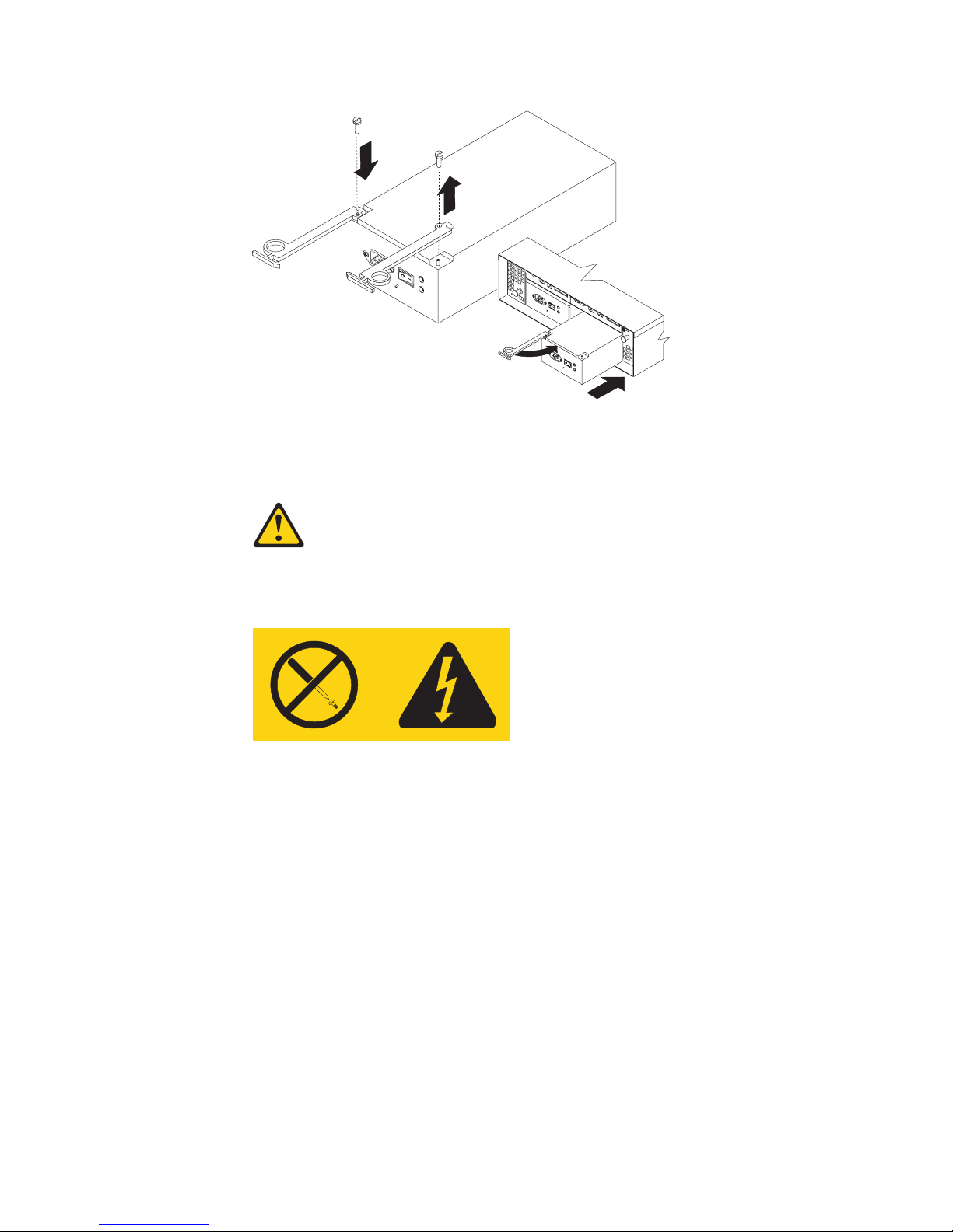
Figure 47. Installing a hot-swap power supply
To install a hot-swap power supply, perform the following steps:
Statement 8
CAUTION:
Never remove the cover on a power supply or any part that has the following label
attached.
Hazardous voltage, current, and energy levels are present inside any component that
has this label attached. There are no serviceable parts inside these components. If you
suspect a problem with one of these parts, contact a service technician.
1. Ensure that the ac power switch is off on the power supply that you are
installing.
2. Install the power supply in the storage server, as follows:
a. Slide the power supply into the storage server. Make sure that the lever is
pulled straight out as you slide the power supply into the storage server.
b. Close the lever until the pull-ring latch locks in place. Make sure that the
lever locks into place in the storage-server chassis.
3. Wrap the strain-relief clamp around the power cord approximately 20 cm (8 in.)
from the power-supply connection end.
4. Attach the power-supply nut and tighten it securely.
5. Connect the power cord to the AC power connector. See Figure 48 on page 63.
62 IBM TotalStorage FAStT600 Fibre Channel Storage Server: Installation and User’s Guide
Page 93
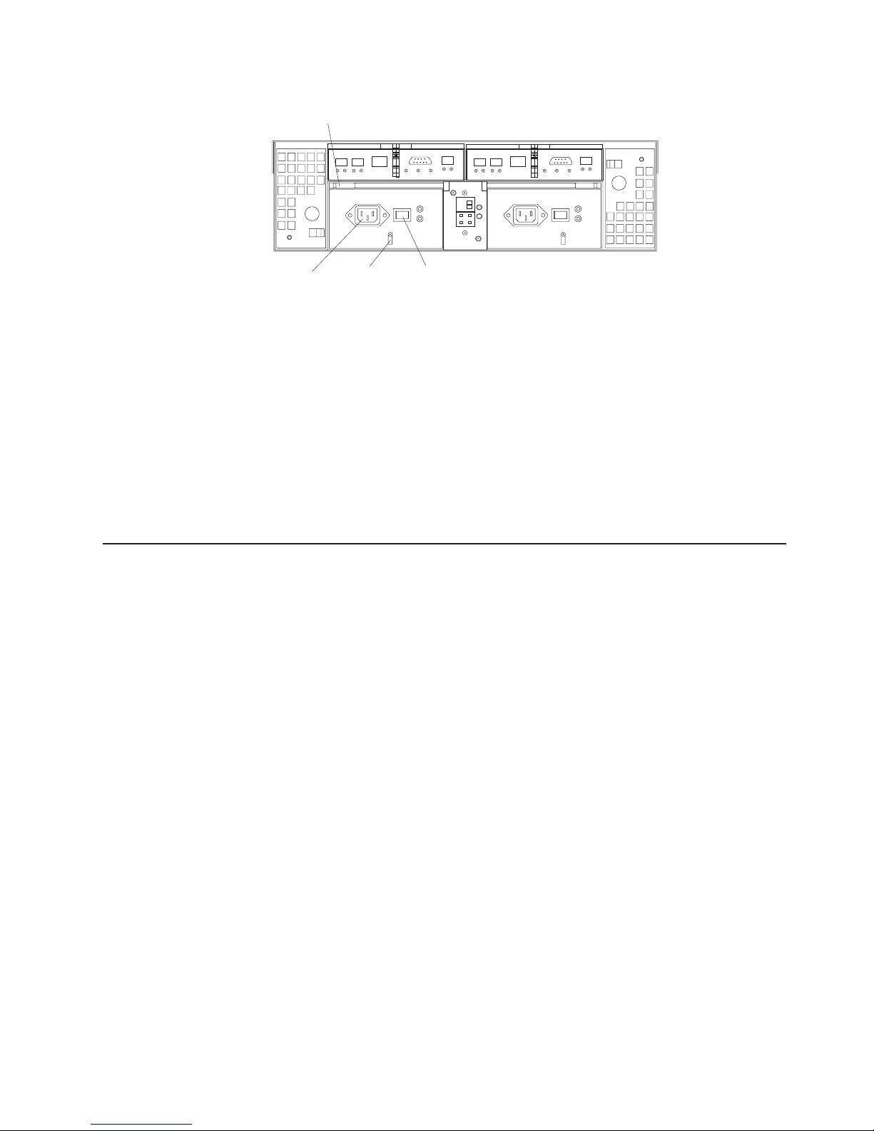
Lever
AC power
connector
Figure 48. Connecting the power cord to the AC power connector
Strain-relief
clamp
-
AC power
switch
6. Plug the power cord into a properly grounded electrical outlet.
7. Turn on the power-supply switch.
8. Make sure that the green Power LED on the new power-supply CRU is on and
the amber Fault LED is off.
v If the Power LED is off, the power-supply CRU might not be installed
correctly. Remove it and then reinstall it.
v If the Fault LED is on or the Power LED stays off, see the
storage-management software for problem determination.
For more information about the LEDs, see “Checking the LEDs” on page 42.
Working with hot-swap RAID controllers
Each RAID controller fits into the back of the storage server and has the following
components:
v Battery
v Cache memory
v Two host ports and one expansion port
v One Ethernet port
v One serial port
Each RAID controller has a unique hardware Ethernet address, which is printed on
a label on the front. There is also a label giving the cache battery manufacturing
and installation dates on the top of the controller unit. Figure 49 on page 64 shows
the location of these items.
Chapter 5. Installing and replacing components 63
Page 94

Ethernet address label
Levers
Figure 49. RAID controller levers and labels
For information about the RAID controller cache memory and rechargeable battery,
see “Cache memory and RAID controller battery” on page 46.
Replacing a RAID controller
When instructed to do so by the storage-management software, replace a RAID
controller that has failed.
Battery-access panel (on bottom)
|
|
|
|
|
|
|
|
Important: The replacement RAID controller CRU does not come with a RAID
controller cache battery installed, nor the mounting hardware that holds
the battery in place inside the RAID controller. You must remove the
cache battery that is inside the existing RAID controller that you are
replacing, and install that battery inside the replacement RAID controller
CRU, using the battery unit mounting hardware taken from the existing
controller. The steps to remove and replace the battery are included in
the following procedure.
To replace a RAID controller, perform the following steps:
1. Check the storage-management software for instructions on RAID controller
failure-recovery procedures. Follow the steps provided in the software
documentation before continuing with step 2.
2. Label each cable that connects to the RAID controller that has failed. This
ensures that all cables will be properly reconnected to the new RAID controller.
Attention: Handle and install fiber-optic cables properly to avoid degraded
performance or loss of communications with devices. When working with
fiber-optic cables, do not pinch them, step on them, or locate them in aisles or
walkways. Do not overtighten the cable straps or bend the cables to a radius
smaller than 38 mm (1.5 in.).
3. From the RAID controller that has failed, remove the fibre-channel cables from
the SFPs. The location of these components is shown in Figure 50 on page 65.
64 IBM TotalStorage FAStT600 Fibre Channel Storage Server: Installation and User’s Guide
Page 95

SFP module
Raid controller
Fiber-optic
cable
Figure 50. Location of SFPs and fiber-optic cables
After removing the fibre-channel cables, insert the protective caps.
4. Use the following procedure to remove the SFPs from the RAID controller that
has failed.
a. Remove the LC-LC fibre-channel cable from the SFP module. For more
information, see “Handling fiber-optic cables” on page 27.
b. Unlock the SFP module latch:
v For SFP modules that contain plastic tabs, unlock the SFP module latch
by pulling the plastic tab outward 10°, as shown in Figure 51.
Plastic tab
Protective cap
o
10
SFP module
Figure 51. Unlocking the SFP module latch - plastic variety
v For SFP modules that contain wire tabs, unlock the SFP module latch by
pulling the wire latch outward 90°, as shown in Figure 26 on page 30.
Chapter 5. Installing and replacing components 65
Page 96
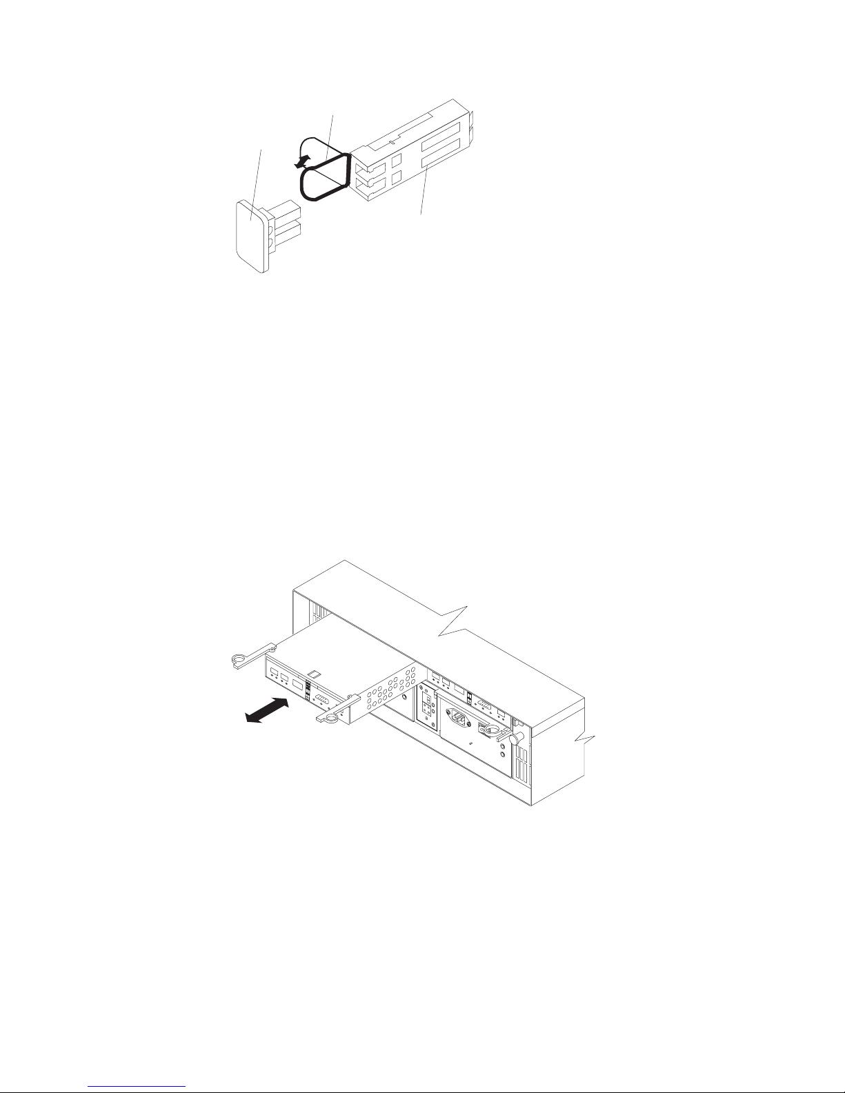
Wire tab
Protective cap
o
90
SFP module
Figure 52. Unlocking the SFP module latch - wire variety
c. With the SFP latch in the unlocked position, extract the SFP module.
v For SFP modules that contain plastic tabs, slide the SFP module out of
the port.
v For SFP modules that contain wire tabs, grasp the wire latch and pull
the SFP module out of the minihub port.
d. Replace the protective cap on the SFP module.
e. Place the SFP module into a static-protective package.
f. Replace the protective cap on the port.
5. Remove the failed RAID controller (the Fault LED is on), as follows:
a. Push down on the latch (centered above the RAID controller). Pull both
levers at the same time out of the locked position.
Figure 53. Pull-rings for removing a controller
b. Grasp the pull-rings; then pull on the levers and remove the RAID
controller.
6. To remove the cache battery, place the RAID controller CRU bottom up on a
flat surface. Using a #2 Phillips head screwdriver, remove the six screws (three
on each side of the RAID controller) that hold the RAID controller bottom panel
to the sides of the RAID controller, as shown in Figure 54 on page 67.
66 IBM TotalStorage FAStT600 Fibre Channel Storage Server: Installation and User’s Guide
Page 97

Figure 54. Controller battery-access panel screws
7. Slide the RAID controller bottom panel away from the front side of the RAID
controller (away from the SFP slots and black center latch) to unlatch it from
the side panels.
8. Carefully flip over the RAID controller bottom panel. Disconnect the battery
harness on the battery from the two-pin connector on the controller board, as
shown in Figure 55.
Battery Harness
Two-Pin
Battery
Figure 55. Removing the controller battery
9. Remove the screw that holds the battery access panel. Carefully slide the
access panel toward the front to unlatch it from the three pins mounted on the
RAID controller bottom panel.
10. Remove the battery unit and place it on a dry, level surface. If this is a battery
replacement, then replace the old battery with the new one and go to step 17
on page 68.
11. Unpack the new RAID controller.
Set the RAID controller on a dry, level surface away from magnetic fields. Save
the packing material and documentation in case you need to return the RAID
controller.
12. Place the replacement RAID controller CRU bottom up on a flat surface. Using
a #2 Phillips head screwdriver, remove the six screws (three on each side of
Chapter 5. Installing and replacing components 67
Page 98

the RAID controller) that hold the RAID controller bottom panel to the sides of
the RAID controller, as shown in Figure 54 on page 67.
13. Slide the RAID controller bottom panel away from the front side of the RAID
controller (away from the SFP slots and black center latch) to unlatch it from
the side panels.
14. Carefully flip over the RAID controller bottom panel.
15. Remove the screw that holds the battery access panel. Carefully slide the
access panel toward the front to unlatch it from the three pins mounted on the
RAID controller bottom panel.
16. Write the battery replacement information on the label on the battery pack.
v Installed date – Write today’s date
v Replacement Date – Write the date three years from today’s date
Note: The preferred method of checking for the battery operating age is
through the storage server management software.
17. Position the battery inside the replacement RAID controller.
|
|
|
|
|
|
|
18. Reassemble the battery access panel to the RAID controller bottom panel by
aligning it with the three pins on the RAID controller bottom panel. Slide the
battery access panel toward the back until you can reinsert the screw that
holds the battery access panel to the RAID controller bottom panel. Do not
overtighten.
19. You must reconnect the battery harness to the two-pin connector on the
controller board.
|
|
Note: The connector is keyed so that there is only one way to attach the
harness to the connector. Do not force fit.
20. Flip the RAID controller bottom panel over and carefully place it on the
controller sides. Push the RAID controller bottom panel toward the front to
latch it to the side panels. If the controller bottom panel is placed correctly, you
should be able to access the mounting holes for the six screws that you
removed from step 6 on page 66. Reinsert the six screws. Do not overtighten.
21. Install the new RAID controller, as follows:
a. Slide the RAID controller all the way into the empty slot.
b. Close both levers until the latch locks into place.
Attention: When you replace the failed RAID controller, the
storage-management software automatically synchronizes the firmware
between the existing controller and the new controller. After you replace a
controller, always use the storage-management software to verify the firmware
levels and NVSRAM files.
22. Insert the SFPs according to the instructions in “Installing SFP modules” on
page 28.
23. Connect the fibre-channel cables to their original locations, according to the
instructions in “Installing fiber-optic cables” on page 30.
24. Wait approximately one minute, and then check the green Host Loop LED,
green Expansion Loop LED, and amber Fault LED on the new RAID controller.
v If the Host Loop LED or the Expansion Loop LED is off, the RAID controller
might not be inserted correctly. Remove the CRU and reinsert it.
v If the Fault LED is on, the Host Loop LED and the Expansion Loop LED
stay off, or any other Fault LED is on, see the storage-management
software for problem determination.
68 IBM TotalStorage FAStT600 Fibre Channel Storage Server: Installation and User’s Guide
Page 99

25. See the storage-management software online help for instructions on bringing
the controller online.
Replacing the battery in the RAID controller
Each RAID controller contains a rechargeable battery that maintains the data in the
cache memory for three days without power to the unit.
Use the following procedure if the storage-management software instructs you to
replace the battery because the current battery has failed or is nearing its expiration
date. You can also use the storage-management software to check the status of the
battery.
1. Check the storage-management software for instructions on battery
replacement procedures. If you are not using write-cache mirroring, this might
involve clearing cache memory on the RAID controller that contains the battery
that has failed. This is done by either placing the controller offline before
removing it from the FAStT600 server or turning off caching in the FAStT600
server, using storage-management software. Follow the steps given in the
software procedure before you continue with this procedure.
Attention: When you handle static-sensitive devices, take precautions to
avoid damage from static electricity. For details about handling static-sensitive
devices, see “Handling static-sensitive devices” on page 49.
2. Unpack the new battery.
Set the new battery on a dry, level surface. Save all packing materials in case
you need to return the battery.
Note: The battery comes with a new battery label. You will need this label
later in the procedure.
3. Review all documentation that comes with the new battery for updated
replacement procedures and other information.
4. Use the storage-management software to locate the RAID controller that
contains the failed battery (the RAID controller Fault LED might be on).
5. Label each cable that connects to the RAID controller that contains the battery
that has failed. This ensures that all cables will be properly reconnected to the
RAID controller after you replace the battery.
6. Use the storage management software to take offline the RAID controller that
contains the battery that has failed.
Attention: To prevent data loss, you must shutdown the system before you
can replace the RAID controller battery. For the proper shutdown sequence,
see “Turning off the storage server” on page 39.
7. Remove the fibre-channel cables and the SFPs from the RAID controller that
contains the battery that has failed or is nearing its expiration date. For more
information, see “Working with SFPs and fiber-optic cables” on page 27.
8. Remove the RAID controller as described in “Replacing a RAID controller” on
page 64.
9. To remove the cache battery, place the RAID controller CRU bottom up on a
flat surface. Using a #2 Phillips head screwdriver, remove the six screws (three
on each side of the RAID controller) that hold the RAID controller bottom panel
to the sides of the RAID controller, as shown in Figure 54 on page 67.
10. Slide the RAID controller bottom panel away from the front side of the RAID
controller (away from the SFP slots and black center latch) to unlatch it from
the side panels.
Chapter 5. Installing and replacing components 69
Page 100

11. Carefully flip over the RAID controller bottom panel. Disconnect the battery
harness on the battery from the two-pin connector on the controller board as
shown in Figure 55 on page 67.
12. Remove the screw that holds the battery access panel. Carefully slide the
access panel toward the front to unlatch it from the three pins mounted on the
RAID controller bottom panel.
13. Remove the battery unit and place it on a dry, level surface. If this battery is a
replacement battery, then replace the old battery with the new one.
14. Write the battery replacement information on the label on the battery pack.
v Installed date – Write today’s date
v Replacement Date – Write the date three years from today’s date
Note: The preferred method of checking for the battery operating age is
through the storage server management software.
CONTAINS
SEALED LEAD
BATTERY.
BATTERY
MUST BE
RECYCLED.
Pb
CAUTION:
Use proper facilities to recycle the used battery CRU. If the battery CRU
is physically damaged or leaking electrolyte gel, do not ship it to a
recycling center. The battery contains sealed lead-acid batteries that
might be considered hazardous material. You must handle this unit in
accordance with all applicable local and federal regulations.
15. Position the replacement battery inside the RAID controller.
16. Reassemble the battery access panel to the RAID controller bottom panel by
aligning it with the three pins on the RAID controller bottom panel. Slide the
battery access panel toward the back until you can reinsert the screw that
holds the battery access panel to the RAID controller bottom panel. Do not
overtighten
17. You must reconnect the battery harness to the two-pin connector on the
controller board.
Note: The connector is keyed so that there is only one way to attach the
hardness to the connector. Do not force fit.
18. Flip the RAID controller bottom panel over and carefully place it on the
controller sides. Push the RAID controller bottom panel toward the front to
latch it to the side panels. If the controller bottom panel is placed correctly, you
should be able to access the mounting holes for the six screws that you
removed in step 6 on page 66. Reinsert the six screws. Do not overtighten.
19. Dispose of the used battery CRU according to local and federal regulations,
which might include hazardous material handling procedures.
In the United States, IBM has established a collection process for reuse,
recycling, or proper disposal of used IBM sealed lead acid batteries. For
information on proper disposal of these batteries, please contact your IBM
70 IBM TotalStorage FAStT600 Fibre Channel Storage Server: Installation and User’s Guide
 Loading...