

Page 1

RS/6000 Enterprise Server Model F80
Eserver
pSeries 620 Models 6F0 and 6F1
Service Gui de
SA38-0568-03
Page 2

Fourth Edition (April 2002)
Before using this information and the product it supports, read the information in “Safety Notices” on page xi,
Appendix A, “Environmental Notices,” on page 389, and on page 0.
A reader’s comment form is provided at the back of this publication. If the form has been removed, address comments
to Information Development, Department H6DS-905-6C006, 11501 Burnet Road, Austin, Texas 78758-3493. To send
comments electronically, use this commercial internet address: aix6kpub@austin.ibm.com. Any information that you
supply may be used without incurring any obligation to you.
© International Business Machines Corporation, 2000, 2002. All rights reserved. Note to U.S. Government Users
-- Documentation related to restricted rights -- Use, duplication or disclosure is subject to restrictions set forth is GSA
ADP Schedule Contract with IBM Corp.
Page 3

Contents
Safety Notices . . . . . . . . . . . . . . . . . . . . . . . .xi
Electrical Safety . . . . . . . . . . . . . . . . . . . . . . . xii
Laser Safety Information . . . . . . . . . . . . . . . . . . . . . xii
Laser Compliance . . . . . . . . . . . . . . . . . . . . . . xii
Data Integrity and Verification . . . . . . . . . . . . . . . . . .xv
About This Book . . . . . . . . . . . . . . . . . . . . . . xvii
ISO 9000 . . . . . . . . . . . . . . . . . . . . . . . . . xvii
Online Publications . . . . . . . . . . . . . . . . . . . . . . xvii
Related Publications . . . . . . . . . . . . . . . . . . . . . . xvii
Trademarks . . . . . . . . . . . . . . . . . . . . . . . . xviii
Chapter 1. Reference Information . . . . . . . . . . . . . . . . .1
Overview . . . . . . . . . . . . . . . . . . . . . . . . . .2
Bus Architecture . . . . . . . . . . . . . . . . . . . . . . .3
Microprocessor . . . . . . . . . . . . . . . . . . . . . . .3
Memory . . . . . . . . . . . . . . . . . . . . . . . . .4
Media Drives . . . . . . . . . . . . . . . . . . . . . . . .4
Internal Hard Disk Drives . . . . . . . . . . . . . . . . . . . .4
Power Supply . . . . . . . . . . . . . . . . . . . . . . .4
Keyboard . . . . . . . . . . . . . . . . . . . . . . . . .4
Mouse . . . . . . . . . . . . . . . . . . . . . . . . . .4
Operator Panel . . . . . . . . . . . . . . . . . . . . . . .5
Input/Output Ports . . . . . . . . . . . . . . . . . . . . . .5
Security Features . . . . . . . . . . . . . . . . . . . . . .5
Data Flow with One-Way Processor . . . . . . . . . . . . . . . . .6
Data Flow with Two- to Six-Way Processor . . . . . . . . . . . . . . .7
Power Flow . . . . . . . . . . . . . . . . . . . . . . . . .8
Powering Off and Powering On the System . . . . . . . . . . . . . . .9
Powering Off the System . . . . . . . . . . . . . . . . . . . .9
Powering On the System . . . . . . . . . . . . . . . . . . . .9
Powering Off and Powering On the System Using the Service Processor . . . .9
Console Strategy . . . . . . . . . . . . . . . . . . . . . . .10
Power-On Self-Test . . . . . . . . . . . . . . . . . . . . . .10
POST Indicators . . . . . . . . . . . . . . . . . . . . . . .10
POST Keys . . . . . . . . . . . . . . . . . . . . . . . . .11
1 Key . . . . . . . . . . . . . . . . . . . . . . . . . .11
5 Key . . . . . . . . . . . . . . . . . . . . . . . . . .11
6 Key . . . . . . . . . . . . . . . . . . . . . . . . . .12
8 Key . . . . . . . . . . . . . . . . . . . . . . . . . .12
System Unit Locations . . . . . . . . . . . . . . . . . . . . .13
Front View . . . . . . . . . . . . . . . . . . . . . . . .13
Rear View . . . . . . . . . . . . . . . . . . . . . . . .14
System Board . . . . . . . . . . . . . . . . . . . . . . .15
Operator Panel . . . . . . . . . . . . . . . . . . . . . . .16
System Memory . . . . . . . . . . . . . . . . . . . . . . .16
iii
Page 4

One-Way Processor Memory Placement Rules . . . . . . . . . . . .16
Riser Card Memory Placement Rules . . . . . . . . . . . . . . .17
Logical and Physical Locations . . . . . . . . . . . . . . . . . .17
Physical Location Codes . . . . . . . . . . . . . . . . . . . .17
Location Code Format . . . . . . . . . . . . . . . . . . . .17
Multiple FRU Callout Instructions . . . . . . . . . . . . . . . . .18
AIX Location Codes . . . . . . . . . . . . . . . . . . . . . .19
AIX and Physical Location Code Reference Tables . . . . . . . . . . .21
Memory Riser Card and Memory DIMM Locations . . . . . . . . . . .23
One-Way Processor Card Memory DIMM Locations . . . . . . . . . .24
Specifications . . . . . . . . . . . . . . . . . . . . . . . .30
Dimensions . . . . . . . . . . . . . . . . . . . . . . . .30
Weight . . . . . . . . . . . . . . . . . . . . . . . . .31
Operating Environment . . . . . . . . . . . . . . . . . . . .31
Operating Voltage . . . . . . . . . . . . . . . . . . . . . .31
Heat Output (Maximum) . . . . . . . . . . . . . . . . . . . .31
Acoustics . . . . . . . . . . . . . . . . . . . . . . . .32
External AC Power Cables . . . . . . . . . . . . . . . . . . . .32
Service Inspection Guide . . . . . . . . . . . . . . . . . . . .33
Chapter 2. Diagnostics Overview . . . . . . . . . . . . . . . . .35
Maintenance Analysis Procedures (MAPs) . . . . . . . . . . . . . . .35
Checkpoints . . . . . . . . . . . . . . . . . . . . . . . . .36
FRU Isolation . . . . . . . . . . . . . . . . . . . . . . . .37
Electronic Service Agent for the Eserver pSeries and RS/6000 . . . . . . .37
Using the Service Processor and Electronic Service Agent Features . . . . . .38
Service Processor . . . . . . . . . . . . . . . . . . . . . .38
Electronic Service Agent . . . . . . . . . . . . . . . . . . .39
Chapter 3. Maintenance Analysis Procedures (MAPs) . . . . . . . . . .41
Entry MAP . . . . . . . . . . . . . . . . . . . . . . . . .41
Quick Entry MAP . . . . . . . . . . . . . . . . . . . . . . .42
Quick Entry MAP Table of Contents . . . . . . . . . . . . . . . .42
MAP 1020: Problem Determination . . . . . . . . . . . . . . . . .48
Purpose of this MAP . . . . . . . . . . . . . . . . . . . . .48
MAP 1520: Power . . . . . . . . . . . . . . . . . . . . . . .53
Step 1520-1 . . . . . . . . . . . . . . . . . . . . . . . .53
Step 1520-2 . . . . . . . . . . . . . . . . . . . . . . . .54
Step 1520-3 . . . . . . . . . . . . . . . . . . . . . . . .54
Step 1520-4 . . . . . . . . . . . . . . . . . . . . . . . .55
Step 1520-5 . . . . . . . . . . . . . . . . . . . . . . . .55
Step 1520-6 . . . . . . . . . . . . . . . . . . . . . . . .56
Step 1520-7 . . . . . . . . . . . . . . . . . . . . . . . .56
MAP 1540: Minimum Configuration . . . . . . . . . . . . . . . . .57
Purpose of this MAP . . . . . . . . . . . . . . . . . . . . .57
SSA Maintenance Analysis Procedures (MAPs) . . . . . . . . . . . . .75
Using SSA MAPs . . . . . . . . . . . . . . . . . . . . . .75
MAP 2010: SSA Hot-Swap Disk Drive–Start . . . . . . . . . . . . . .77
Step 2010-1 . . . . . . . . . . . . . . . . . . . . . . . .77
Step 2010-2 . . . . . . . . . . . . . . . . . . . . . . . .77
iv Service Guide
Page 5

Step 2010-3 . . . . . . . . . . . . . . . . . . . . . . . .78
Step 2010-4 . . . . . . . . . . . . . . . . . . . . . . . .78
Step 2010-5 . . . . . . . . . . . . . . . . . . . . . . . .78
Step 2010-6 . . . . . . . . . . . . . . . . . . . . . . . .78
Step 2010-7 . . . . . . . . . . . . . . . . . . . . . . . .78
Step 2010-8 . . . . . . . . . . . . . . . . . . . . . . . .79
Step 2010-9 . . . . . . . . . . . . . . . . . . . . . . . .79
Step 2010-10 . . . . . . . . . . . . . . . . . . . . . . .79
Step 2010-11 . . . . . . . . . . . . . . . . . . . . . . .79
Step 2010-12 . . . . . . . . . . . . . . . . . . . . . . .79
Step 2010-13 . . . . . . . . . . . . . . . . . . . . . . .80
MAP 2323: SSA hot-swap disk drive Intermittent Link Verification . . . . . . .80
Step 2323-1 . . . . . . . . . . . . . . . . . . . . . . . .80
Step 2323-2 . . . . . . . . . . . . . . . . . . . . . . . .80
Step 2323-3 . . . . . . . . . . . . . . . . . . . . . . . .81
MAP 2324: SSA hot-swap disk drive RAID . . . . . . . . . . . . . .81
Chapter 4. Checkpoints . . . . . . . . . . . . . . . . . . . .83
IPL Flow . . . . . . . . . . . . . . . . . . . . . . . . . .83
Service Processor Checkpoints . . . . . . . . . . . . . . . . . .85
Firmware Checkpoints . . . . . . . . . . . . . . . . . . . . .91
Boot Problems and Concerns . . . . . . . . . . . . . . . . . . 102
Step 1 . . . . . . . . . . . . . . . . . . . . . . . . . 102
Step 2 . . . . . . . . . . . . . . . . . . . . . . . . . 102
Step 3 . . . . . . . . . . . . . . . . . . . . . . . . . 103
Step 4 . . . . . . . . . . . . . . . . . . . . . . . . . 103
Step 5 . . . . . . . . . . . . . . . . . . . . . . . . . 104
Chapter 5. Error Code to FRU Index . . . . . . . . . . . . . . . 105
Four-Character Checkpoints . . . . . . . . . . . . . . . . . . . 105
Operator Panel Replacement . . . . . . . . . . . . . . . . . . 105
Replacing the Network Adapter . . . . . . . . . . . . . . . . . . 105
Determining Location Code . . . . . . . . . . . . . . . . . . . 105
Checkpoint and Error Code Index . . . . . . . . . . . . . . . . . 106
Performing Slow Boot . . . . . . . . . . . . . . . . . . . . . 107
Confirming Initial Error Code . . . . . . . . . . . . . . . . . . . 107
Memory-Related Error Codes . . . . . . . . . . . . . . . . . . 108
Operator Panel Error Codes . . . . . . . . . . . . . . . . . . . 109
SPCN Error Codes . . . . . . . . . . . . . . . . . . . . . .110
Firmware Error Codes . . . . . . . . . . . . . . . . . . . . .117
Service Processor Error Codes . . . . . . . . . . . . . . . . . . 138
System Firmware Update Messages . . . . . . . . . . . . . . . . 239
Common Firmware Error Codes . . . . . . . . . . . . . . . . . . 239
Scan Log Dump Progress Codes . . . . . . . . . . . . . . . . . 248
Problem Determination-Generated Error Codes . . . . . . . . . . . . 248
Chapter 6. Loading the System Diagnostics In Service Mode . . . . . . . 251
Default Boot List and Service Mode Bootlist . . . . . . . . . . . . . . 252
Chapter 7. Using the Service Processor . . . . . . . . . . . . . . 253
Contents v
Page 6

Service Processor Menus . . . . . . . . . . . . . . . . . . . . 254
Accessing the Service Processor Menus Locally . . . . . . . . . . . 254
Accessing the Service Processor Menus Remotely . . . . . . . . . . 254
Saving and Restoring Service Processor Settings . . . . . . . . . . . 254
Menu Inactivity . . . . . . . . . . . . . . . . . . . . . . 255
General User Menu . . . . . . . . . . . . . . . . . . . . . . 255
Privileged User Menus . . . . . . . . . . . . . . . . . . . . . 256
Main Menu . . . . . . . . . . . . . . . . . . . . . . . . 256
Service Processor Setup Menu . . . . . . . . . . . . . . . . . 258
Passwords . . . . . . . . . . . . . . . . . . . . . . . . 259
System Power Control Menu . . . . . . . . . . . . . . . . . . 262
System Information Menu . . . . . . . . . . . . . . . . . . . 266
Memory Riser Card 1 Memory DIMM Locations for Service Processor Menus 270
Memory Riser Card 2 Memory DIMM Locations for Service Processor Menus 271
Processor Card Memory DIMM Locations for Service Processor Menus . . . 271
Language Selection Menu . . . . . . . . . . . . . . . . . . 273
Call-In/Call-Out Setup Menu . . . . . . . . . . . . . . . . . . 274
Modem Configuration Menu . . . . . . . . . . . . . . . . . . 275
Serial Port Selection Menu . . . . . . . . . . . . . . . . . . 276
Serial Port Speed Setup Menu . . . . . . . . . . . . . . . . . 276
Telephone Number Setup Menu . . . . . . . . . . . . . . . . . 277
Call-Out Policy Setup Menu . . . . . . . . . . . . . . . . . . 278
Customer Account Setup Menu . . . . . . . . . . . . . . . . . 279
Service Processor Procedures in Service Mode . . . . . . . . . . . . 279
Service Processor Functions . . . . . . . . . . . . . . . . . . . 280
System Power-On Methods . . . . . . . . . . . . . . . . . . . 281
Service Processor Reboot/Restart Recovery . . . . . . . . . . . . . 282
Boot (IPL) Speed . . . . . . . . . . . . . . . . . . . . . 282
Failure During Boot Process . . . . . . . . . . . . . . . . . . 282
Failure During Normal System Operation . . . . . . . . . . . . . . 282
Service Processor Reboot/Restart Policy Controls . . . . . . . . . . . 282
System Firmware Updates . . . . . . . . . . . . . . . . . . . 284
General Information on System Firmware Updates . . . . . . . . . . 284
Determining the Level of Firmware on the System . . . . . . . . . . . 285
System Firmware Update Using a Locally Available Image . . . . . . . . 285
Updating System Firmware From the Service Processor Menus . . . . . . 286
Updating System Firmware from the AIX Service Aids . . . . . . . . . 286
Updating System Firmware from the AIX Command Line . . . . . . . . 286
Recovery Mode . . . . . . . . . . . . . . . . . . . . . . 286
Configuring and Deconfiguring Processors or Memory . . . . . . . . . . 287
Run-Time CPU Deconfiguration (CPU Gard) . . . . . . . . . . . . 288
Service Processor System Monitoring - Surveillance . . . . . . . . . . . 288
System Firmware Surveillance . . . . . . . . . . . . . . . . . 288
Operating System Surveillance . . . . . . . . . . . . . . . . . 288
Call-Out (Call-Home) . . . . . . . . . . . . . . . . . . . . . 289
Console Mirroring . . . . . . . . . . . . . . . . . . . . . . 291
System Configuration . . . . . . . . . . . . . . . . . . . . 291
Service Processor Error Log . . . . . . . . . . . . . . . . . . . 292
LCD Progress Indicator Log . . . . . . . . . . . . . . . . . . . 293
Service Processor Operational Phases . . . . . . . . . . . . . . . 294
vi Service Guide
Page 7

Pre-Standby Phase . . . . . . . . . . . . . . . . . . . . . 294
Standby Phase . . . . . . . . . . . . . . . . . . . . . . 294
Bring-Up Phase . . . . . . . . . . . . . . . . . . . . . . 295
Run-Time Phase . . . . . . . . . . . . . . . . . . . . . . 296
Chapter 8. Using System Management Services . . . . . . . . . . . 297
Password Utilities . . . . . . . . . . . . . . . . . . . . . . 298
Display Error Log . . . . . . . . . . . . . . . . . . . . . . 299
Remote Initial Program Load Setup . . . . . . . . . . . . . . . . 299
IP Parameters . . . . . . . . . . . . . . . . . . . . . . 300
Adapter Parameters . . . . . . . . . . . . . . . . . . . . . 301
Ping . . . . . . . . . . . . . . . . . . . . . . . . . . 302
SCSI Utilities . . . . . . . . . . . . . . . . . . . . . . . . 303
Select Console . . . . . . . . . . . . . . . . . . . . . . . 303
MultiBoot . . . . . . . . . . . . . . . . . . . . . . . . . 304
Select Software . . . . . . . . . . . . . . . . . . . . . . 304
Software Default . . . . . . . . . . . . . . . . . . . . . . 304
Select Install Device . . . . . . . . . . . . . . . . . . . . 304
Select Boot Devices . . . . . . . . . . . . . . . . . . . . 305
OK Prompt . . . . . . . . . . . . . . . . . . . . . . . . 306
Multiboot Startup <OFF> . . . . . . . . . . . . . . . . . . . 306
Select Language . . . . . . . . . . . . . . . . . . . . . . . 307
OK Prompt . . . . . . . . . . . . . . . . . . . . . . . . . 307
Exiting System Management Services . . . . . . . . . . . . . . . . 307
Chapter 9. Removal and Replacement Procedures . . . . . . . . . . 309
Handling Static-Sensitive Devices . . . . . . . . . . . . . . . . . 310
Removal and Replacement Procedures . . . . . . . . . . . . . . . 310
Covers . . . . . . . . . . . . . . . . . . . . . . . . . .311
Removing the Covers . . . . . . . . . . . . . . . . . . . .311
Replacing Covers . . . . . . . . . . . . . . . . . . . . . 314
Removing Processor and Memory Riser Card Cover . . . . . . . . . . . 315
Replacing Processor and Memory Riser Card Cover . . . . . . . . . . 315
Hot-Pluggable FRUs . . . . . . . . . . . . . . . . . . . . . 316
Hot-Pluggable Options . . . . . . . . . . . . . . . . . . . . . 316
Stopping the System Unit . . . . . . . . . . . . . . . . . . . . 316
Disk Drive Options . . . . . . . . . . . . . . . . . . . . . . 317
Disk Drive Slot LED Definitions . . . . . . . . . . . . . . . . . 318
Preinstallation Considerations . . . . . . . . . . . . . . . . . 319
Removing Hot-Plug SCSI Disk Drives . . . . . . . . . . . . . . . 319
Replacing Hot-Plug SCSI Disk Drives . . . . . . . . . . . . . . . 321
Configuring and Deconfiguring SCSI Hot-Swap Disk Drives . . . . . . . 323
Removing Hot-Plug SSA Disk Drives . . . . . . . . . . . . . . . 324
Replacing Hot-Plug SSA Disk Drives . . . . . . . . . . . . . . . 326
PCI Adapter Options . . . . . . . . . . . . . . . . . . . . . 328
PCI Slot LED Definitions . . . . . . . . . . . . . . . . . . . 328
Removing Adapter Cards . . . . . . . . . . . . . . . . . . . . 329
Removing a Non-Hot-Pluggable PCI Adapter . . . . . . . . . . . . 329
Removing a Hot-Pluggable PCI Adapter . . . . . . . . . . . . . . 330
Replacing Adapter Cards . . . . . . . . . . . . . . . . . . . . 332
Contents vii
Page 8

Replacing a Non-Hot-Pluggable PCI Adapter . . . . . . . . . . . . 333
Replacing a Hot-Pluggable PCI Adapter . . . . . . . . . . . . . . 334
PCI Hot-Plug Manager Access . . . . . . . . . . . . . . . . . . 336
Accessing Hot-Plug Management Functions . . . . . . . . . . . . . 336
PCI Hot-Plug Manager Menu . . . . . . . . . . . . . . . . . . 337
Fans and Fan Fillers . . . . . . . . . . . . . . . . . . . . . 338
Removal . . . . . . . . . . . . . . . . . . . . . . . . 338
Replacement . . . . . . . . . . . . . . . . . . . . . . . 338
Power Supplies . . . . . . . . . . . . . . . . . . . . . . . 338
Removal . . . . . . . . . . . . . . . . . . . . . . . . 339
Replacement . . . . . . . . . . . . . . . . . . . . . . . 339
Installing the Redundant Power and Cooling Option . . . . . . . . . . . 339
Installing a Redundant Fan . . . . . . . . . . . . . . . . . . 339
Installing a Redundant Power Supply . . . . . . . . . . . . . . . 340
Memory Riser Card and Processor Card . . . . . . . . . . . . . . . 342
Removing a Memory Riser Card or One-Way Processor Card . . . . . . . 342
Installing a Memory Riser Card or a One-Way Processor Card . . . . . . 343
Memory and Processor Card CEC Assembly . . . . . . . . . . . . . 344
Removal . . . . . . . . . . . . . . . . . . . . . . . . 344
Replacement . . . . . . . . . . . . . . . . . . . . . . . 344
System Memory Options . . . . . . . . . . . . . . . . . . . . 345
Memory Placement with a One-Way Processor Card . . . . . . . . . . 345
Memory Placement for a Memory Riser Card . . . . . . . . . . . . 346
Memory DIMMs . . . . . . . . . . . . . . . . . . . . . . . 346
Removing Memory DIMMs . . . . . . . . . . . . . . . . . . 346
Replacement . . . . . . . . . . . . . . . . . . . . . . . 348
Processor Card . . . . . . . . . . . . . . . . . . . . . . 349
Removal . . . . . . . . . . . . . . . . . . . . . . . . 349
Replacement . . . . . . . . . . . . . . . . . . . . . . . 349
Battery . . . . . . . . . . . . . . . . . . . . . . . . . . 349
Removal . . . . . . . . . . . . . . . . . . . . . . . . 350
Replacement . . . . . . . . . . . . . . . . . . . . . . . 350
Operator Panel . . . . . . . . . . . . . . . . . . . . . . . 351
Removal . . . . . . . . . . . . . . . . . . . . . . . . 351
Operator Panel Cable . . . . . . . . . . . . . . . . . . . . . 353
Removal . . . . . . . . . . . . . . . . . . . . . . . . 353
PCI Adapter Dividers . . . . . . . . . . . . . . . . . . . . . 353
Removal . . . . . . . . . . . . . . . . . . . . . . . . 353
Replacement . . . . . . . . . . . . . . . . . . . . . . . 354
System Board Assembly . . . . . . . . . . . . . . . . . . . . 354
Removal . . . . . . . . . . . . . . . . . . . . . . . . 354
Replacement . . . . . . . . . . . . . . . . . . . . . . . 355
Internal Disk Drive Bays . . . . . . . . . . . . . . . . . . . . 355
Removing a Two-Position SCSI Disk Drive Bay . . . . . . . . . . . 356
Replacing a Two-Position SCSI Disk Drive Bay . . . . . . . . . . . . 357
Removing Six-Position SCSI (SES) or SSA Disk Drive Bays . . . . . . . 358
Replacing Six-Position SCSI (SES) or SSA Disk Drive Bays . . . . . . . 362
SCSI and SSA Cabling Configurations . . . . . . . . . . . . . . . 366
Two-Position SCSI Disk Drive Bay Cabling . . . . . . . . . . . . . 366
First Six-Position SCSI Disk Drive Bay Cabling . . . . . . . . . . . . 367
viii Service Guide
Page 9

Second Six-Position SCSI Disk Drive Bay Cabling . . . . . . . . . . . 368
Two Six-Position SCSI RAID Bays Connected to a Single RAID Adapter . . . 368
One Six-Position SCSI RAID Bay and One Six-Position SSA Bay . . . . . 369
Two Six-Position SSA Bays Connected to the Same SSA Loop . . . . . . 369
Replacing Non-Hot-Plug Drives . . . . . . . . . . . . . . . . . . 370
Removing a Media Drive from the Optional Media Position . . . . . . . . 370
Replacing a Media Drive in the Optional Media Position . . . . . . . . . 371
Removing a Disk Drive from the Two-Position Disk Drive Bay . . . . . . . 371
Replacing a Disk Drive in the Two-Position Disk Drive Bay . . . . . . . . 373
Chapter 10. Parts Information . . . . . . . . . . . . . . . . . . 375
Covers . . . . . . . . . . . . . . . . . . . . . . . . . . 375
Right Side . . . . . . . . . . . . . . . . . . . . . . . . . 376
Left Side . . . . . . . . . . . . . . . . . . . . . . . . . 379
Accessories . . . . . . . . . . . . . . . . . . . . . . . . 382
Power Cords . . . . . . . . . . . . . . . . . . . . . . . 382
Keyboards and Mouse (White) . . . . . . . . . . . . . . . . . 384
Keyboards and Mouse (Black) . . . . . . . . . . . . . . . . . 386
Appendix A. Environmental Notices . . . . . . . . . . . . . . . . 389
Product Recycling and Disposal . . . . . . . . . . . . . . . . . . 389
Environmental Design . . . . . . . . . . . . . . . . . . . . . 393
Acoustical Noise Emissions . . . . . . . . . . . . . . . . . . . 394
Declared Acoustical Noise Emissions . . . . . . . . . . . . . . . . 394
Appendix B. Notices . . . . . . . . . . . . . . . . . . . . . 395
Product Recycling and Disposal . . . . . . . . . . . . . . . . . . 395
Battery Return Program . . . . . . . . . . . . . . . . . . . . 396
Appendix C. Service Processor Setup and Test . . . . . . . . . . . 397
Service Processor Setup Checklist . . . . . . . . . . . . . . . . . 397
Testing the Setup . . . . . . . . . . . . . . . . . . . . . . 398
Testing Call-In . . . . . . . . . . . . . . . . . . . . . . 398
Testing Call-Out . . . . . . . . . . . . . . . . . . . . . . 398
Serial Port Configuration . . . . . . . . . . . . . . . . . . . 399
Appendix D. Modem Configurations . . . . . . . . . . . . . . . 401
Sample Modem Configuration Files . . . . . . . . . . . . . . . . 401
Generic Modem Configuration Files . . . . . . . . . . . . . . . 401
Specific Modem Configuration Files . . . . . . . . . . . . . . . 401
Configuration File Selection . . . . . . . . . . . . . . . . . . . 402
Examples for Using the Generic Sample Modem Configuration Files . . . . 403
Customizing the Modem Configuration Files . . . . . . . . . . . . . 404
IBM 7852-400 DIP Switch Settings . . . . . . . . . . . . . . . . 405
Xon/Xoff Modems . . . . . . . . . . . . . . . . . . . . . 405
Ring Detection . . . . . . . . . . . . . . . . . . . . . . 406
Terminal Emulators . . . . . . . . . . . . . . . . . . . . . 406
Recovery Procedures . . . . . . . . . . . . . . . . . . . . 406
Transfer of a Modem Session . . . . . . . . . . . . . . . . . . 407
Recovery Strategy . . . . . . . . . . . . . . . . . . . . . 408
Contents ix
Page 10

Prevention Strategy . . . . . . . . . . . . . . . . . . . . . 408
Modem Configuration Sample Files . . . . . . . . . . . . . . . . 409
Sample File modem_m0.cfg . . . . . . . . . . . . . . . . . . 409
Sample File modem_m1.cfg . . . . . . . . . . . . . . . . . .411
Sample File modem_z.cfg . . . . . . . . . . . . . . . . . . . 413
Sample File modem_z0.cfg . . . . . . . . . . . . . . . . . . 415
Sample File modem_f.cfg . . . . . . . . . . . . . . . . . . . 417
Sample File modem_f0.cfg . . . . . . . . . . . . . . . . . . 419
Sample File modem_f1.cfg . . . . . . . . . . . . . . . . . . 421
Appendix E. SSA Problem Determination Procedures . . . . . . . . . 425
Disk Drive Module Power-On Self-Tests (POSTs) . . . . . . . . . . . . 425
Adapter Power-On Self-Tests (POSTs) . . . . . . . . . . . . . . . 425
Appendix F. SSA Software and Microcode Errors . . . . . . . . . . . 427
Service Request Numbers (SRNs) . . . . . . . . . . . . . . . . . 427
SRN Table . . . . . . . . . . . . . . . . . . . . . . . . 427
Using the SRN Table . . . . . . . . . . . . . . . . . . . . 427
Software and Microcode Errors . . . . . . . . . . . . . . . . . 428
FRU Names and Abbreviations Used in the SRN Table . . . . . . . . . 428
SSA Loop Configurations That Are Not Valid . . . . . . . . . . . . . 436
SSA Location Code Format . . . . . . . . . . . . . . . . . . . 437
SSA Loops and Links . . . . . . . . . . . . . . . . . . . . . 438
The SSA Adapter . . . . . . . . . . . . . . . . . . . . . 438
Disk Drive Module Strings . . . . . . . . . . . . . . . . . . . 439
Pdisks, Hdisks, and Disk Drive Module Identification . . . . . . . . . . 439
Rules for SSA Loops . . . . . . . . . . . . . . . . . . . . 440
Loops and Data Paths . . . . . . . . . . . . . . . . . . . . 440
Index . . . . . . . . . . . . . . . . . . . . . . . . . . 443
x Service Guide
Page 11

Safety Notices
A danger notice indicates the presence of a hazard that has the potential of causing
death or serious personal injury. Danger notices appear on the following pages:
v xii
v 53
v 309
v 339
A
caution notice indicates the presence of a hazard that has the potential of causing
moderate or minor personal injury. Caution notices appear on the following pages:
v xii
v xii
v 53
v 309
v 370
Note:
For a translation of these notices, see the System Unit Safety Information
manual, order number SA23-2652.
xi
Page 12

Electrical Safety
Observe the following safety instructions any time you are connecting or disconnecting
devices attached to the server.
DANGER
An
electrical outlet that is not correctly wired could place hazardous voltage
on metal parts of the system or the devices that attach to the system. It is the
responsibility of the customer to ensure that the outlet is correctly wired and
grounded to prevent an electrical shock.
Before installing or removing signal cables, ensure that the power cables for
the system unit and all attached devices are unplugged.
When adding or removing any additional devices to or from the system,
ensure that the power cables for those devices are unplugged before the
signal cables are connected. If possible, disconnect all power cables from the
existing system before you add a device.
Use one hand, when possible, to connect or disconnect signal cables to
prevent a possible shock from touching two surfaces with different electrical
potentials.
During an electrical storm, do not connect cables for display stations, printers,
telephones, or station protectors for communications lines.
D05
CAUTION:
This product is equipped with a three-wire power cable and plug for the user’s
safety. Use this power cable with a properly grounded electrical outlet to avoid
electrical shock.
C01
Laser Safety Information
CAUTION:
This product may contain a CD-ROM, DVD-ROM, or laser module on a PCI card,
which are class 1 laser products.
C30
Laser Compliance
All lasers are certified in the U.S. to conform to the requirements of DHHS 21 CFR
Subchapter J for class 1 laser products. Outside the U.S., they are certified to be in
compliance with the IEC 825 (first edition 1984) as a class 1 laser product. Consult the
label on each part for laser certification numbers and approval information.
xii Service Guide
Page 13

CAUTION:
All IBM laser modules are designed so that there is never any human access to
laser radiation above a class 1 level during normal operation, user maintenance,
or prescribed service conditions. Data processing environments can contain
equipment transmitting on system links with laser modules that operate at
greater than class 1 power levels. For this reason, never look into the end of an
optical fiber cable or open receptacle. Only trained service personnel should
perform the inspection or repair of optical fiber cable assemblies and receptacles.
C25,
C26
Preface xiii
Page 14

xiv Service Guide
Page 15

Data Integrity and Verification
IBM computer systems contain mechanisms designed to reduce the possibility of
undetected data corruption or loss. This risk, however, cannot be eliminated. Users who
experience unplanned outages, system failures, power fluctuations or outages, or
component failures must verify the accuracy of operations performed and data saved or
transmitted by the system at or near the time of the outage or failure. In addition, users
must establish procedures to ensure that there is independent data verification before
relying on such data in sensitive or critical operations. Users should periodically check
the IBM support websites for updated information and fixes applicable to the system and
related software.
xv
Page 16

xvi Service Guide
Page 17

About This Book
This book provides maintenance information that is specific to the Enterprise Server
Model F80 and Eserver pSeries 620 Models 6F0 and 6F1, as well as to adapters and
attached devices that do not have their own service information. In this book, the
Enterprise Server Model F80 and Eserver pSeries 620 Models 6F0 and 6F1 are
hereafter referred to as the ″system″ or the ″server.″
This book also contains Maintenance Analysis Procedures (MAPs) that are not common
to other systems. MAPs that are common to all systems are contained in the RS/6000
and Eserver pSeries Diagnostic Information for Multiple Bus Systems.
This book is used by the service technician to repair system failures. This book
assumes that the service technician has had training on the system unit.
ISO 9000
ISO 9000 registered quality systems were used in the development and manufacturing
of this product.
Online Publications
RS/6000 and pSeries publications are available online. To access the online books, visit
our Web site at: http://www.rs6000.ibm.com/resource/hardware_docs/
Related Publications
The following publications are available for purchase:
v The System Unit Safety Information, order number SA23-2652, contains translations
of safety information used throughout this book.
v The RS/6000 Enterprise Server Model F80, Eserver pSeries 620 Models 6F0 and
6F1 User’s Guide, order number SA38-0567, contains information to help users set
up, install options, configure and modify the system, and solve minor problems.
v The RS/6000 and Eserver pSeries Diagnostic Information for Multiple Bus Systems,
order number SA38-0509, contains common diagnostic procedures, error codes,
service request numbers, and failing function codes. This manual is intended for
trained service technicians.
v The PCI Adapter Placement Reference, order number SA38-0538, contains
guidelines for placement of PCI adapters into I/O slots of Models F80, 6F0, and 6F1
systems. This manual is intended to help when planning to install adapters so that
optimum, tested adapter configurations are used.
v The RS/6000 and Eserver pSeries Adapters, Devices, and Cable Information for
Multiple Bus Systems, order number SA38-0516, contains information about
adapters, external devices, and cabling. This manual is intended to supplement
information found in the RS/6000 and Eserver pSeries Diagnostic Information for
Multiple Bus Systems.
xvii
Page 18

v The Site and Hardware Planning Information, order number SA38-0508, contains
information to help you plan your installation.
v SSA Adapters User’s Guide and Maintenance Information, order number SA33-3272,
is intended to help users and service representatives work with and diagnose
problems with SSA adapters and devices.
v RS/6000 SP Systems Service Guide, order number GA22-7442, is intended to help
users and service representatives work with and diagnose problems with SP
systems.
v Clustered Eserver Installation and Service Guide, order number SA22-7863, is
intended to help users and service representatives work with and diagnose problems
with clustered Eserver systems.
Trademarks
The following terms are trademarks of International Business Machines Corporation in
the United States, other countries, or both:
v AIX
v RS/6000
v pSeries
v e (logo)
Other
company, product, and service names may be trademarks or service marks of
others.
xviii Service Guide
Page 19

Chapter 1. Reference Information
This chapter provides an overview of the system, including a logical description and a
physical overview of the system. Additional details pertaining to the system are also
provided. These include:
v Memory overview and placement rules
v General description of the operator panel
v System location rules and descriptions
v Powering on and off the system
v Power flow
v Data flow
1
Page 20
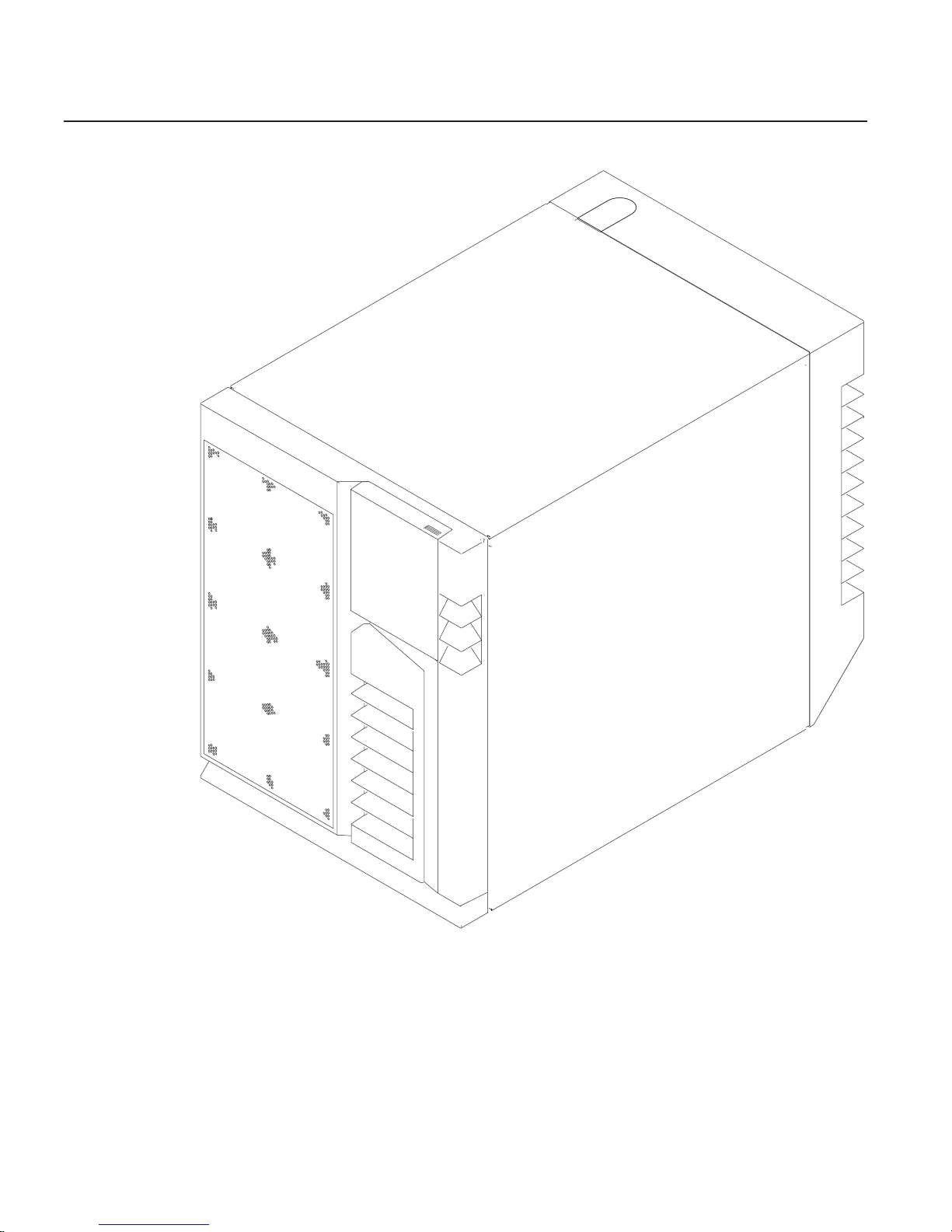
Overview
This system is a high-performance entry server in a deskside system unit. It provides
64-bit symmetric multiprocessing (SMP) with true multithreaded application support in a
double-wide deskside box.
2 Service Guide
Page 21

Bus Architecture
Te n PCI slots are available:
v Six of the slots are 64-bit PCI full-sized slots at 66 MHz, 3.3 volts.
v Four of the slots are 64-bit PCI full-sized slots at 33 MHz, 5 volts.
v
Bus 1 contains:
– PCI slot 3
– PCI slot 4
– PCI slot 5
– Integrated Ultra2 SCSI
v
Bus 2 contains:
– PCI slot 6
– PCI slot 7
– PCI slot 8
– Integrated Ethernet (32-bit)
v
Bus 3 contains:
– PCI slot 9
– PCI slot 10
– PCI slot 11
– PCI slot 12
The PCI buses support both 32-bit and 64-bit adapters. Slots 3, 4, 5, 8, 9, and 10
support adapters running at 3.3 volts at up to 66 MHz. Slots 6, 7, 11, and 12 support
adapters running at 5 volts at 33 MHz. The server data flows are shown in “Data Flow
with One-Way Processor” on page 6 and “Data Flow with Two- to Six-Way Processor”
on page 7.
Microprocessor
The Models F80 and 6F1 can have one to six processors, of either of two processor
types, in various configurations:
v Minimum configuration is one 450 MHz processor, which has 2 MB of L2 cache.
v Two or four 450 MHz processors, each with 4 MB of L2 cache.
v Six 500 MHz processors, each with 4 MB of L2 cache.
OR
v Minimum configuration is either one 600 MHz processor, which has 2 MB of L2
cache, or one 750 MHz processor, which has 8 MB of L2 cache.
v Two or four 600 MHz processors, each with 4 MB of L2 cache.
v Two or four 750 MHz processors, each with 8 MB of L2 cache.
v Six 668 MHz processors, each with 8 MB of L2 cache.
v Six 750 MHz processors, each with 8 MB of L2 cache.
The
Model 6F0 can have one to four processors, of either of two processor types, in
various configurations:
v Minimum configuration is one 450 MHz processor, which has 2 MB of L2 cache.
v Two or four 450 MHz processors, each with 4 MB of L2 cache.
OR
Chapter 1. Reference Information 3
Page 22

v Minimum configuration is either one 600 MHz processor, which has 2 MB of L2
cache, or one 750 MHz processor, which has 8 MB of L2 cache.
v Two or four 600 MHz processors, each with 4 MB of L2 cache.
v Two or four 750 MHz processors, each with 8 MB of L2 cache.
Memory
v 256 MB (minimum) to 32 GB (maximum).
v One or two memory riser cards; each riser card has 16 sockets. 128 MB, 256 MB,
512 MB and 1 GB dual inline memory modules (DIMMs) are available.
v Certain 32 MB DIMMs from older systems can also be used when upgrading the
system memory.
Media Drives
Three media bays are available:
v Optional media bay (D17) that can accommodate 5.25-inch drives such as CD-ROM
drives, tape drives, or other removable media drives
v Standard CD-ROM drive with sliding tray (D16)
v Standard 3.5-inch, 1.44 MB diskette drive (D15)
Internal Hard Disk Drives
Three bays are available to install disk drives, as follows:
v Disk bay 3, a two-position SCSI disk drive bay (D13 and D14)
This bay supports two SCSI disk drives.
v Disk bay 2, a six-position hot-plug disk drive bay (D07 - D12)
This bay can accommodate a six-position SCSI disk drive cage or a six-position SSA
disk drive cage.
v Disk bay 1, a six-position hot-plug disk drive bay (D01 - D06)
This bay can accommodate a six-position SCSI disk drive cage or a six-position SSA
disk drive cage.
Power Supply
v 575-watt power supply (two required), usable with 100-127 V ac (low voltage) or
200-240 V ac (high voltage)
Keyboard
v Standard: 101-key enhanced keyboard
v Optional: 101/102-key or 106-key enhanced keyboard
Mouse
v Three-button
4 Service Guide
Page 23

Operator Panel
v 32-character LED diagnostics display
v Power and Reset buttons
Input/Output Ports
v 25-pin parallel
v 9-pin serial (4)
v Keyboard
v Mouse
v Ultra 2 SCSI LVD
v 10/100BaseT Ethernet
Security Features
v Power-on password
v Privileged-access password
v Unattended start mode
Chapter 1. Reference Information 5
Page 24

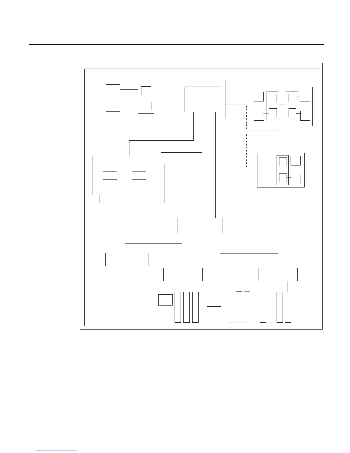
Data Flow with One-Way Processor
System Board
L2
Processor Card (1 way only)Processor Card (1 way only)
6XX
Bus 0
P
Memory Card
(1 only is optional)
Memory Card
(1 only is optional)
SMI BUS 0, 1
SMI
SMI
SMI
SMI
SMI
SMI
SMI BUS 2, 3
64-bit
PCI Bus 2
64-bit
PCI Bus 2
RIO
(2)
PCI Host Bridge
Memory
Controller
Memory
Controller
64-bit
PCI Bus 1
64-bit
PCI Bus 1
PCI to PCI
Bridge 3
PCI to PCI
Bridge 3
5V5V
PCI to PCI
Bridge 2
PCI to PCI
Bridge 2
5V5V
3.3
V
3.3
V
3.3V3.3
V
3.3V3.3
V
3.3V3.3
V
3.3V3.3
V
3.3V3.3
V
PCI to PCI
Bridge 1
PCI to PCI
Bridge 1
Converged Support
Processor
Converged Support
Processor
S
L
O
T
3
S
L
O
T
3
S
L
O
T
6
S
L
O
T
6
S
L
O
T
9
S
L
O
T
9
S
L
O
T
4
S
L
O
T
4
S
L
O
T
7
S
L
O
T
7
S
L
O
T
10
S
L
O
T
10
S
L
O
T
5
S
L
O
T
5
S
L
O
T
8
S
L
O
T
8
S
L
O
T
11
S
L
O
T
11
S
L
O
T
12
S
L
O
T
12
SCSI
10/100
E’net
10/100
E’net
256 MB - 16 GB
6 Service Guide
Page 25
Data Flow with Two- to Six-Way Processor
System Board
L2
2-Way System
6XX
Bus 0
L2
P
P
L2
L2
P
6XX
Bus 1
Memory Cards
(1 or 2)
Memory Cards
(1 or 2)
256 MB - 32 GB
SMI BUS 0, 1
SMI
SMI
SMI
SMI
SMI BUS 2, 3
64-bit
PCI Bus 2
64-bit
PCI Bus 2
RIO
(2)
6-Way System
L2
L2
P
4-Way System
OR
L2
L2
P
P P
P
PCI Host Bridge
Memory
Controller
Memory
Controller
64-bit
PCI Bus 1
64-bit
PCI Bus 1
10/100
E’net
10/100
E’net
PCI to PCI
Bridge 3
PCI to PCI
Bridge 3
5V
5V
PCI to PCI
Bridge 2
PCI to PCI
Bridge 2
3.3V3.3
V
5V
5V
3.3
V
3.3
V
3.3V3.3
V
3.3V3.3
V
3.3V3.3
V
3.3V3.3
V
PCI to PCI
Bridge 1
PCI to PCI
Bridge 1
Converged Support
Processor
Converged Support
Processor
S
L
O
T
3
S
L
O
T
3
S
L
O
T
7
S
L
O
T
7
S
L
O
T
6
S
L
O
T
6
S
L
O
T
4
S
L
O
T
4
S
L
O
T
8
S
L
O
T
8
S
L
O
T
10
S
L
O
T
10
S
L
O
T
9
S
L
O
T
9
S
L
O
T
5
S
L
O
T
5
S
L
O
T
11
S
L
O
T
11
S
L
O
T
12
S
L
O
T
12
SCSI
Chapter 1. Reference Information 7
Page 26

Power Flow
The following diagram shows the right side of the system with the cover removed.
1
2
3
45
6
7
8
9
10
11
12
13
14
15
16
17
18
19
20
1 110 V ac/220 V ac power into system
board assembly
11 Power 1 to DASD bay 1 (DB1)
2 110 V ac/220 V ac power into power
supply V1
12 Power 1 to DASD bay 2 (DB2)
3 2.5 V dc out of power supply V1 into
system board
13 Power to cooling fans
4 2.5/3.3 V dc out of power supply V1 into
system board
14 Power 2 to DASD bay 2 (DB2)
5 3.3 V dc out of power supply V1 into
system board
15 Signal to diskette drive
6 5 V dc out of power supply V1 into
system board
16 I2C to DASD bay 2 (DB2)
7 Ground out of power supply V1 into
system board
17 Power to diskette drive
8 12 V dc out of power supply V1 into
system board
18 Signal to operator panel
9 I2C to DASD bay 1 (DB1) 19 Power to media drive bay
10 Power 2 to DASD bay 1 (DB1) 20 Power 1 to two-position disk drive bay 3
(DB3)
8 Service Guide
Page 27

Powering Off and Powering On the System
This section provides procedures for powering off and powering on the system.
Powering Off the System
If the system is operating under AIX, type the shutdown command to power off the
system.
If you cannot use this method, you can power off the system by using the following
operator-panel power button procedure:
Attention: Using the operator-panel power button to power off the system might
cause unpredictable results in the data files, and the next IPL will take longer to
complete.
1. Open the access door.
2. Press the power button on the operator panel.
B0FF appears in the operator panel display. The operator panel power LED starts
blinking at a fast rate.
When
the power-off sequence is complete, the system goes into standby power mode,
as evidenced by the following:
v OK displays in the operator panel display.
v The operator panel power LED starts blinking at a slow rate.
Powering On the System
Perform the following steps to power on the system:
1. Open the access door. Look for OK on the operator panel display, which indicates
that the system is in standby mode.
2. Press the power button on the operator panel.
The power LED on the operator panel starts blinking at a fast rate. Checkpoint
codes (9xxx) appear in the operator panel display. For details, see “IPL Flow” on
page 83.
When
the power-on sequence is complete, the power LED on the operator panel stops
blinking and stays on.
Powering Off and Powering On the System Using the Service Processor
The system can be powered off and on using the System Power Control menu, which is
a service processor menu that is available to the privileged user. See “System Power
Control Menu” on page 262.
Chapter 1. Reference Information 9
Page 28

Console Strategy
The firmware starts a console-selection sequence at system boot time if any of the
following is true:
v A console has not yet been selected.
v A previous console selection sequence timed out.
v A change in the system configuration affects the console (keyboard
installed/removed, mouse installed/removed, graphics adapter installed/removed or
moved to another PCI slot).
The
console-selection sequence allows you to select (from the appropriate input device)
one of the available console devices. If no console is selected within approximately 60
seconds, serial port 1 (S1) is selected as the console and the selection sequence times
out.
After a console has been selected, the console-selection sequence is only started at
boot time if there is a change in the system configuration (as described above), or the
contents of the system’s nonvolatile memory (NVRAM) are lost.
Note: Moving an ASCII terminal from one serial port to another (from S1 to S2) cannot
be detected by the firmware, so it does not constitute a configuration change.
You can also initiate a firmware console selection sequence from the System
Management Services (SMS) menus.
Power-On Self-Test
After power is turned on and before the operating system is loaded, the system does a
power-on self-test (POST). This test performs checks to ensure that the hardware is
functioning correctly before the operating system is loaded. During the POST, a POST
screen displays and POST indicators appear on the fimware console (if one is
connected). The next section describes the POST indicators and functions that can be
accessed during the POST.
POST Indicators
POST (power-on self-test) indicators indicate tests that are being performed as the
system is preparing to load the operating system. The POST indicators are words that
display on the system console. Each time that the system starts another step in the
POST, a POST indicator word appears on the console. Each word is an indicator of the
tests that are being performed.
10 Service Guide
Page 29

The POST screen displays the following words:
Memory Memory test
Keyboard Initialize the keyboard and mouse. The window for pressing a key to
access the System Management Services, or to initiate a service
mode boot, is now open. See “POST Keys” for more information.
Network Self-test on network adapters
SCSI Adapters are being initialized
Speaker Sounds an audible tone at the end of POST
POST Keys
The POST keys, if pressed after the keyboard POST indicator displays and before the
last POST indicator (speaker) displays, cause the system to start services or to initiate
service mode boots used for configuring the system and diagnosing problems. The keys
are described below:
Note: The program function keys (F1-F12) on a keyboard attached to the system unit
are no longer used and will be ignored during POST. After the keyboard POST
indicator displays, you must use the numeric number keys to enter input.
1 Key
The numeric 1 key, when pressed during POST, starts the System Management
Services (SMS) interface.
5 Key
The numeric 5 key, when pressed during POST, initiates a system boot in service mode
using the default service mode boot list.
This mode attempts to boot from the first device of each type found in the list. It does
not search for other bootable devices of that type if the first device is not bootable.
Instead, it continues to the next device type in the list. The firmware supports up to five
entries in the boot list.
The default boot sequence is:
1. Diskette
2. CD-ROM
3. Hard file
4. Tape drive (if installed)
5. Network
a. Token ring
b. Ethernet
Chapter 1. Reference Information 11
Page 30

6 Key
The numeric 6 key works like the numeric 5 key, except that firmware uses the
customized service mode bootlist that was set up using the AIX service aids.
8 Key
To enter the open firmware command line, press the numeric 8 key after the word
keyboard displays and before the last word (speaker) displays during startup. After you
press the 8 key, the remaining POST indicators display until initialization completes.
When initialization and POST are complete, the open firmware command line (an OK
prompt) displays.
The open firmware command line should only be used by service personnel to obtain
additional debug information.
To exit from the open firmware command prompt, type reset-all or power off the
system and reboot.
12 Service Guide
Page 31

System Unit Locations
Front View
14
5
6
7
8
4
1
3
2
13
12
11
10
9
1 Media Bay (Optional Drive): Bay D17 -
This position is for installing an optional
media device.
5 & 6 Two-Position SCSI Disk Drive Bay: Bay
D14 (top), Bay D13 (bottom). Bays for
the installation of two SCSI disk drives.
2 CD-ROM Drive: Bay D16 7 & 8 Disk Drive Bay: Bank DB2 (top), Bay
DB1 (bottom) (SES or SSA). Bays for the
installation of SCSI or SSA disk drives or
RAID arrays.
3 Diskette Drive: Bay D15 9 &
10
Disk Drive: Bay D07 (top left), Bay D12
(top right). Bay D01 (bottom left), Bay
D06 (bottom right). Disk drives in a SCSI
or SSA disk drive bay.
4 Operator Panel Display 11 -
14
Fan Positions: Fan F01 (bottom), Fan
F04 (top). Fans F01 and F03 are
required. Fans F02 and F04 are required
only for the redundant power option.
Chapter 1. Reference Information 13
Page 32

Rear View
5
6
7
8
4
1
3
2
10 9
11
12
13
14
12
11
10
09
08
07
06
05
04
03
64-bit 5V Slots
at 33MHz
64-bit 5V Slots
at 33MHz
64-bit 3.3V Slots
at 66MHz
64-bit 3.3V Slots
at 66MHz
1 & 2 Expansion Slots: For adding PCI
adapters.
1 Expansion Slot C12
2 Expansion Slot C3
8 Keyboard Port: For keyboard
connection.
3 Test Port: For testing during
manufacturing.
9 Mouse Port: For mouse connection.
4 Parallel Port: For connecting a parallel
printer or other parallel devices.
10 Power Connector: For connecting the
power cable.
5 External SCSI Port: For connecting
external SCSI devices.
11 &
12
Power Supplies: V1 (bottom), V2
(middle) Power supplies are installed
from the side of the system unit.
6 100BaseT Ethernet Port: For attaching
your computer to an Ethernet/Twisted
pair connection through a 100BaseT
connector.
13 Redundant Power Supply V3
(Optional)
7 9-Pin Serial Ports: For a TTY terminal,
modem, or other serial devices.*
14 Disk Drive Bulkhead Connector: For
attaching internal disk drive bays to an
SSA adapter or connecting internal
hardfiles to the external SCSI port (5) or
a SCSI adapter.
*Serial ports 1 and 2 can only be used for service processor menus. No
″heartbeat-type″ devices can be used on these ports. ″Heartbeat-type″ devices or
cables must be installed on serial port 3 or serial port 4.
14 Service Guide
Page 33

System Board
1
.
.
.
2
5b
4
9
17
12
13
7
5a
10
16
13
14
3
8
6
11
12
15
1 & 2 Expansion Slots: For adding PCI
adapters.
1 Expansion Slot C12
2 Expansion Slot C3
8 11
9-Pin Serial Ports: For a TTY terminal,
modem, or other serial devices.
3 Test Port: For manufacturing use only. 12 Mouse Port
4 Parallel Port 13 Keyboard Port
5 SCSI Port
v 5a Internal Port 1 speed must be set
to fast/wide
v 5b External Port 2 Ultra-2
14 &
15
Memory Riser Card Slots
6 Processor Card Connector 16 Battery
7 100BaseT Ethernet Port 17 Fan Cable Connector
Note: For locations of diskette and operator panel connectors, see “Power Flow” on
page 8. For AIX location codes and physical location codes, see “System Board
Locations” on page 22.
Chapter 1. Reference Information 15
Page 34

Operator Panel
The following diagram shows the locations of the operator panel display and the
operator panel pushbuttons.
R
12 345
8910
11
76
1 Power-On Button 7 Speaker
2 Power-On LED (Green) 8 Serial Number Plate
3 System Attention LED (Yellow) 9 Reset Icon
4 SCSI Activity LED (Green) 10 Reset Button
5 LAN Activity LED (Green) 11 Service Processor Reset Button
6 Operator Panel Display
Note: The service processor reset button must be activated very carefully. An insulated
paper clip is recommended. Unbend the clip so that it has a straight section
about two inches long. Insert the clip straight into the hole, keeping the clip
perpendicular to the plastic bezel. When you engage the reset switch, you
should feel the detent of the switch. After you press the switch, the service
processor resets and then shuts down the system.
System Memory
Two slots are available for memory riser cards. Each riser card had 16 sockets. See
“System Board” on page 15, which illustrates the positions of the memory riser cards in
the system.
Four sizes of DIMMs are available: 128 MB, 256 MB, 512 MB, and 1 GB. Certain 32
MB DIMMs from older RS/6000 systems can also be used when upgrading system
memory.
One-Way Processor Memory Placement Rules
The rules for one-way processor memory are as follows:
v Minimum memory is 1 pair of DIMMs in slots 1 and 8 (see “Processor Card Memory
DIMM Locations for Service Processor Menus” on page 271).
v Maximum memory is 4 DIMM pairs in slots 1 through 8 (see “Processor Card
Memory DIMM Locations for Service Processor Menus” on page 271).
v Each memory riser slot must have a memory filler card installed.
16 Service Guide
Page 35

v When you are installing a memory riser card:
– Memory DIMMs must be moved from the one-way processor card to the memory
riser card.
– The memory riser card must then have a minimum of 1 quad (four DIMMs).
Riser Card Memory Placement Rules
The rules for memory riser cards are as follows:
v Memory quads must contain DIMMs of equal memory size.
v Quad memory size may be mixed on a riser card.
v The minimum memory is four DIMMs, which must occupy quad A, slots 1, 2, 15 and
16 (see “Memory Riser Card and Memory DIMM Locations” on page 23).
v Populate the riser card starting with quad A and continuing with quads B, C, and D
(see “Memory Riser Card and Memory DIMM Locations” on page 23).
Logical and Physical Locations
This system uses physical location codes in conjunction with AIX location codes to
provide mapping of the failing field replaceable units (FRUs). The location codes are
produced by the system unit’s firmware and the AIX operating system.
Physical Location Codes
Physical location codes provide a mapping of logical functions in a platform (or
expansion sites for logical functions, such as connectors or ports) to their specific
locations within the physical structure of the platform.
Location Code Format
The format for the location code is a string of alphanumeric characters separated by a
dash (–), slash (/), pound sign (#) or period (.) character. The base location is all of the
information preceding the slash (/) or pound sign (#). The base location identifies a
device that is connected to or plugged into the parent. Extended location information
follows the slash (/). Extended location information identifies a device that is part of the
parent, a connector, or a cable. Cable information follows the pound sign (#). Cable
information identifies a cable that is connector to parent. The following are examples:
v P1-C1 identifies a processor card C1 plugged into planar P1.
v P1-M1 identifies a memory riser card M1 plugged into planar P1.
v P-1-Z1-A3 identifies a SCSI device with SCSI ID 3 attached to SCSI bus 1 on planar
1.
v P1-K1 identifies a keyboard attached to K1 on planar P1.
v P1/S1 identifies serial port 1 controller on planar P1, the connector for serial port 1,
or the cable attached to serial port 1.
v P1-I2/E3 identifies an Ethernet controller 3, on the card in slot 2 (I2) on planar P1,
the connector for Ethernet controller 3, or the cable attached to Ethernet controller 3.
v P1-I2#E3 identifies the cable attached to Ethernet controller 3 on the card in slot 2
(I2) on planar P1.
Chapter 1. Reference Information 17
Page 36

The period (.) identifies sublocations (DIMMs on a memory riser card, SCSI addresses,
cables). The following are examples:
v P1-M1.4 identifies DIMM 4 on memory riser card 1 plugged into planar P1.
v P1-C1.1 identifies processor 1 on processor card 1 plugged into planar P1.
v P2-Z1-A3.1 identifies a SCSI device with SCSI address of LUN 1 at SCSI ID 3
attached to SCSI bus 1 from planar 2.
v P1-I2#E3.2 identifies the second in a series of cables attached to Ethernet controller
3 on the card in slot 2 (I2) on planar P1.
Depending
on the AIX and firmware levels, AIX diagnostics may include the extended
location information when identifying a planar or card. The extended location
information or cable information is always included when identifying a cable or
connector. Location codes with extended location information that are displayed without
a description identifying the devices always identify the cable attached to the port.
Multiple FRU Callout Instructions
If an eight-digit error code appears in the operator panel display or as described in
Chapter 5, “Error Code to FRU Index,” on page 105, a location code for a failing part
may also be specified. If the location code includes a blank space followed by a
lowercase x followed by a number, this is an error code with multiple FRU callouts. This
error can typically happen with memory DIMMs, memory riser cards, or processors and
may involve mixed types of parts. In this case, check the system’s configuration for
FRU part numbers to determine the appropriate set of FRUs.
For example, if the location code P1-M1.1 x2 was displayed, this indicates memory pair
A (two DIMMs) on the first memory riser card was suspected.
You can determine the FRU part numbers of the electronic assemblies in the system in
two ways:
v Using the service processor menus
From the general user menu, select Read VPD Image from Last System Boot,
then enter 90 to display detailed vital product data (VPD).
v Typing the lscfg -vp | pg command on the AIX command line
Type the following command: lscfg -vp | pg to display the detailed VPD of all
assemblies. Notice that the FRU part number information for processors and memory
DIMMs may be at the bottom of the command output.
18 Service Guide
Page 37

AIX Location Codes
The basic formats of the AIX location codes are as follows:
v For non-SCSI devices/drives:
– AB-CD-EF-GH
v
For SCSI devices/drives:
– AB-CD-EF-G,H
For
planars, cards, and non-SCSI devices, the location code is defined as follows:
AB-CD-EF-GH
| | | |
| | | Device/FRU/Port ID
| | Connector ID
| devfunc Number, Adapter Number or Physical Location
Bus Type or PCI Parent Bus
v The AB value identifies a bus type or PCI parent bus as assigned by the firmware.
v The CD value identifies adapter number, adapter’s devfunc number, or physical
location. The devfunc number is defined as the PCI device number times 8, plus the
function number.
v The EF value identifies a connector.
v The GH value identifies a port, address, device, or FRU.
Adapters
and cards are identified only with AB-CD.
The possible values for CD depend on the adapter/card. For pluggable PCI
adapters/cards, CD is the device’s devfunc number (PCI device number times 8, plus
the function number). The C and D are characters in the range of 0-9, and A-F (hex
numbers). The location codes therefore uniquely identify multiple adapters on individual
PCI cards.
EF is the connector ID, used to identify the adapter’s connector to which a resource is
attached.
GH is used to identify a port, device, or FRU. For example:
v For async devices, GH defines the port on the fanout box. The values are 00 to 15.
v For a diskette drive, H identifies either diskette drive 1 or 2. G is always 0.
v For all other devices, GH is equal to 00.
For
integrated adapter, EF-GH is the same as the definition for a pluggable adapter. For
example, the location code for a diskette drive is 01-D1-00-00. A second diskette drive
is 01-D1-00-01.
Chapter 1. Reference Information 19
Page 38

For SCSI devices, the location code is defined as follows:
AB-CD-EF-G,H
| | | | |
| | | | Logical Unit address of the SCSI Device
| | | Control Unit Address of the SCSI Device
| | Connector ID
| devfunc Number, Adapter Number or Physical Location
Bus Type or PCI Parent Bus
AB-CD-EF are the same as non-SCSI devices.
G defines the control unit address of the device. Values of 0 to 15 are valid.
H defines the logical unit address of the device. Values of 0 to 255 are valid.
A bus location code is also generated as 00-XXXXXXXX, where XXXXXXXX is
equivalent to the node’s unit address.
Examples of physical location codes and AIX location codes are:
v PCI adapter in Slot 1
v Location code P1-I1
v AIX location code 20-58
20 Service Guide
Page 39

AIX and Physical Location Code Reference Tables
The following diagrams identify the physical locations in the system. These locations
correspond to the tables on “System Location Codes” on page 25, which contain
location codes that are used to identify functional units in the system.
The following diagram shows the right side of the system with the cover removed.
Power Supply Locations
AIX
Location
Codes
V3
V2
V1
Physical
Location
Codes
Chapter 1. Reference Information 21
Page 40

System Board Locations
AIX
Location
Codes
P1-I 12
31-08
27-08
P1-I 10
37-08
2D-08
17-08
P1-I 11
34-08
2A-08
P1-I 9
3A-08
14-08
1A-08
P1-I 5
P1-I 7
P1-I 3
P1-I 8
P1-I 4
P1-I 6
Debug
01-R1 P1-R1
11-08 P1-Z1
01-S4 P1-S4
01-S3 P1-S3
01-S1 P1-S1
01-S2 P1-S2
00-00 P1-M1
00-00 P1-M2
Battery
Fan Connector
P1-C1
21-08 P1-E1
01-K1 P1-K1
01-O1 P1-O1
Physical
Location
Codes
Slot
Name
C12
C10
C11
C9
C5
C7
C3
C8
C4
C6
11-09 P1-Z2
Note: See “System Board” on page 15 for descriptions of connectors.
22 Service Guide
Page 41

Memory Riser Card and Memory DIMM Locations
(15) A
(16) A
(14) B
(12) C
(10) D
(8) D
(6) C
(4) B
(2) A
(13) B
(11) C
(9) D
(7) D
(5) C
(3) B
(1) A
Location Code Memory DIMMs
P1-M1.n Memory DIMMs on riser card 1 (n denotes DIMM number)
P1-M2.n Memory DIMMs on riser card 2 (n denotes DIMM number)
P1-M1.1 x4 Memory quad A (DIMMs 1, 2, 15, 16)
P1-M1.3 x4 Memory quad B (DIMMs 3, 4, 13, 14)
P1-M1.5 x4 Memory quad C (DIMMs 5, 6, 11, 12)
P1-M1.7 x4 Memory quad D (DIMMs 7, 8, 9, 10)
P1-M2.1 x2 Memory pair A (DIMMs 1 and 15)
P1-M2.1 x4 Memory quad A (DIMMs 1, 2, 15, 16)
P1-M2.3 x4 Memory quad B (DIMMs 3, 4, 13, 14)
P1-M2.5 x4 Memory quad C (DIMMs 5, 6, 11, 12)
P1-M2.7 x4 Memory quad D (DIMMs 7, 8, 9, 10)
P1-M1.1 x16 All memory DIMMs on riser card 1
P1-M2.1 x16 All memory DIMMs on riser card 2
P1-M1 x2 All memory DIMMs on riser cards 1 and 2
Chapter 1. Reference Information 23
Page 42

One-Way Processor Card Memory DIMM Locations
(8) A
(7) B
(6) C
(5) D
(3) C
(4) D
(2) B
(1) A
Location Code Memory DIMMs
P1-C1-Mn Memory DIMMs on processor card (n denotes DIMM number)
P1-C1-M1 x2 Memory pair A (DIMMs 1 and 8)
P1-C1-M2 x2 Memory pair B (DIMMs 2 and 7)
P1-C1-M3 x2 Memory pair C (DIMMs 3 and 6)
P1-C1-M4 x2 Memory pair D (DIMMs 4 and 5)
P1-C1-M1 x8 All memory DIMMs on processor card
24 Service Guide
Page 43

System Location Codes
If a returned value is not listed in this table, see ″Physical Location Code Standard
Prefixes″ under ″Diagnostic Numbers and Codes″ in RS/6000 and Eserver pSeries
Diagnostic Information for Multiple Bus Systems.
FRU Name Slot
Name
Location
Code
AIX
Location
Code
Physical
Connection
Logical
Connection
System board P1
Processor Card C01 P1-C1
Processor 1 P1-C1 00-00
Processor 2 P1-C1 00-02
Processor 3 P1-C1 00-04
Processor 4 P1-C1 00-06
Processor 5 P1-C1 00-08
Processor 6 P1-C1 00-0A
Memory DIMMs (1-way) P1-C1-M1 to
P1-C1-M8
00-00 See
“One-Way
Processor
Card
Memory
DIMM
Locations”
on page 24
Memory riser card 1 M01 P1-M1 00-00
Memory DIMM 1-16 P1-M1.1 to
P1-M1.16
00-00 See
“Memory
Riser Card
and Memory
DIMM
Locations”
on page 23
Memory riser card 2 M02 P1-M2 00-00
Memory DIMM 1-16 P1-M2.1 to
P1-M2.16
00-00 See
“Memory
Riser Card
and Memory
DIMM
Locations”
on page 23
PCI Host Bridge Bus 1 P1 00-fff7f09000
ISA Bus P1 10-80
PCI to PCI Bridge 1 P1 10-58,
10-5A,
10-5C,
10-5E
Chapter 1. Reference Information 25
Page 44

FRU Name Slot
Name
Location
Code
AIX
Location
Code
Physical
Connection
Logical
Connection
PCI Slot 3 C03 P1/I3 10-5A J10, 64 BIT
See Note 1
on page 30.
PCI to PCI
Bridge 1
PCI Slot 3 Device P1-I3 1A-08 to
1A-0F or
1B-xx or
1C-xx
J10, 64 BIT
See Note 1
on page 30.
PCI to PCI
Bridge 1
PCI Slot 4 C04 P1/I4 10-5C J11, 64 BIT
See Note 1
on page 30.
PCI to PCI
Bridge 1
PCI Slot 4 Device P1-I4 17-08 to
17-0F or
18-xx or
19-xx
J11, 64 BIT
See Note 1
on page 30.
PCI to PCI
Bridge 1
PCI Slot 5 C05 P1/I5 10-5E J12, 64 BIT
See Note 1
on page 30.
PCI to PCI
Bridge 1
PCI Slot 5 Device P1-I5 14-08 to
14-0F or
15-xx or
16-xx
J12, 64 BIT
See Note 1
on page 30.
PCI to PCI
Bridge 1
Internal SCSI controller P1/Z1 11-08 PCI to PCI
Bridge 1
External SCSI controller P1/Z2 11-09 PCI to PCI
Bridge 1
PCI Host Bridge Bus 2 P1 00-fff7f0a000
PCI to PCI Bridge 2 P1 20-58,
20-5A,
20-5B
(unused),
20-5C,
20-5E
PCI Slot 6 C06 P1/I6 20-5A J13, 64 BIT
See Note 1
on page 30.
PCI to PCI
Bridge 2
PCI Slot 6 Device P1-I6 2D-08 to
2D-0F or
2E-xx or
2F-xx
J13, 64 BIT
See Note 1
on page 30.
PCI to PCI
Bridge 2
PCI Slot 7 C07 P1/I7 20-5C J14, 64 BIT
See Note 1
on page 30.
PCI to PCI
Bridge 2
26 Service Guide
Page 45

FRU Name Slot
Name
Location
Code
AIX
Location
Code
Physical
Connection
Logical
Connection
PCI Slot 7 Device P1-I7 2A-08 to
2A-0F or
2B-xx or
2C-xx
J14, 64 BIT
See Note 1
on page 30.
PCI to PCI
Bridge 2
PCI Slot 8 C08 P1/I8 20-5E J14, 64 BIT
See Note 1
on page 30.
PCI to PCI
Bridge 2
PCI Slot 8 Device P1-I8 27-08 to
27-0F or
28-xx or
29-xx
J14, 64 BIT
See Note 1
on page 30.
PCI to PCI
Bridge 2
Integrated Ethernet P1/E1 21-08 PCI to PCI
Bridge 2
PCI to PCI Bridge 3 P1 20-60,
20-62,
20-63,
20-64, 20-65
(unused),
20-66,
PCI Slot 9 C09 P1/I9 20-60 J16, 64 BIT
See Note 1
on page 30.
PCI to PCI
Bridge 3
PCI Slot 9 Device P1-I9 3A-08 to
3A-0F or
3B-xx or
3C-xx
J16, 64 BIT
See Note 1
on page 30.
PCI to PCI
Bridge 3
PCI Slot 10 C10 P1/I10 20-62 J17, 64 BIT
See Note 1
on page 30.
PCI to PCI
Bridge 3
PCI Slot 10 Device P1-I10 37-08 to
37-0F or
38-xx or
39-xx
J17, 64 BIT
See Note 1
on page 30.
PCI to PCI
Bridge 3
PCI Slot 11 C11 P1/I11 20-64 J18, 64 BIT
See Note 1
on page 30.
PCI to PCI
Bridge 3
PCI Slot 11 Device P1-I11 34-08 to
34-0F or
35-xx or
36-xx
J18, 64 BIT
See Note 1
on page 30.
PCI to PCI
Bridge 3
PCI Slot 12 C12 P1/I12 20-66 J19, 64 BIT
See Note 1
on page 30.
PCI to PCI
Bridge 3
Chapter 1. Reference Information 27
Page 46

FRU Name Slot
Name
Location
Code
AIX
Location
Code
Physical
Connection
Logical
Connection
PCI Slot 12 Device P1-I12 31-08 to
31-0F or
32-xx or
33-xx
J19, 64 BIT
See Note 1
on page 30.
PCI to PCI
Bridge 3
Diskette Controller P1/D1 01-D1
Diskette Drive D15 P1-D1 01-D1-00-00
Keyboard Controller/Connector P1/K1 01-K1-00
Keyboard P1-K1 01-K1-00-00
Mouse Controller P1/K1 01-K1-01
Mouse Connnector P1/O1 01-K1-01
Mouse P1-O1 01-K1-01-00
Parallel Port Controller P1/R1 01-R1
Serial Port 1 Controller P1/S1 01-S1
Serial Port 2 Controller P1/S2 01-S2
Serial Port 3 Controller P1/S3 01-S3
Serial Port 4 Controller P1/S4 01-S4
TOD Battery P1-V4
System Firmware P1/Y1
Service Processor Firmware P1/Y2
PRD Code P1/Y2
SPCN Firmware P1/Y3
SPCN VPD P1/Y4
Operator Panel NB1 L1
Operator Panel VPD Module L1-N1
Fan 1 F01 F1
Fan 2 F02 F2
Fan 3 F03 F3
Fan 4 F04 F4
Power Supply 1 V1
Power Supply 2 V2
Power Supply 3 V3
DASD 6-Pack 1 backplane
(SES or SSA)
DB1 B1 SCSI:
xx-xx-0015,0
SSA:
See Note 4
on page 30.
See Note 3
on page 30.
28 Service Guide
Page 47

FRU Name Slot
Name
Location
Code
AIX
Location
Code
Physical
Connection
Logical
Connection
DASD 6-Pack 1, Drive 1 D1 B1.1 SCSI:
xx-xx-00-8,0
SSA: See
Note 4 on
page 30.
DASD 6-Pack 1, Drive 2 D2 B1.2 SCSI:
xx-xx-00-9,0
SSA: See
Note 4 on
page 30.
DASD 6-Pack 1, Drive 3 D3 B1.3 SCSI:
xx-xx-0010,0
SSA:
See Note 4
on page 30.
DASD 6-Pack 1, Drive 4 D4 B1.4 SCSI:
xx-xx-0011,0
SSA:
See Note 4
on page 30.
DASD 6-Pack 1, Drive 5 D5 B1.5 SCSI:
xx-xx-0012,0
SSA:
See Note 4
on page 30.
DASD 6-Pack 1, Drive 6 D6 B1.6 SCSI:
xx-xx-0013,0
SSA:
See Note 4
on page 30.
DASD 6-Pack 2 backplane
(SES or SSA)
DB2 B2 SCSI:
xx-xx-0015,0
SSA:
See Note 4
on page 30.
See Note 3
on page 30.
DASD 6-Pack 2, Drive 1 D7 B2.1 SCSI:
xx-xx-00-8,0
SSA: See
Note 4 on
page 30.
DASD 6-Pack 2, Drive 2 D8 B2.2 SCSI:
xx-xx-00-9,0
SSA: See
Note 4 on
page 30.
Chapter 1. Reference Information 29
Page 48

FRU Name Slot
Name
Location
Code
AIX
Location
Code
Physical
Connection
Logical
Connection
DASD 6-Pack 2, Drive 3 D9 B2.3 SCSI:
xx-xx-0010,0 SSA:
See Note 4.
DASD 6-Pack 2, Drive 4 D10 B2.4 SCSI:
xx-xx-0011,0
SSA:
See Note 4.
DASD 6-Pack 2, Drive 5 D11 B2.5 SCSI:
xx-xx-0012,0
SSA:
See Note 4.
DASD 6-Pack 2, Drive 6 D12 B2.6 SCSI:
xx-xx-0013,0 SSA:
See Note 4.
2-Pack DASD Drive 1 D13 P1-Z1-A4 11-08-00-4,0 See Note 2.
2-Pack DASD Drive 2 D14 P1-Z1-A2 11-08-00-2,0 See Note 2.
Tape Drive D17 P1-Z1-A0 11-08-00-0,0 See Note 2.
CD-ROM Drive D16 P1-Z1-A1 11-08-00-1,0 See Note 2.
Notes:
1. The physical location code for the PCI slots, when empty, uses the P1/Ix notation,
where the ’/’ identifies an integrated device (in this case the empty slot). A PCI
device plugged into the slot uses the P1-Ix notation, where the ’–’ identifies a
plugged device.
2. 11 is for the integrated SCSI device. -4,0 and -2,0 are hardcoded on the DASD
2-pack; -0,0 is the tape drive; -1,0 is the CD-ROM.
3. xx-xx is dependent on which SCSI controller is driving the 6-pack.
4. Use the link verification utility in the SSA service aids under AIX diagnostics to
identify individual SSA drives.
Specifications
This section contains specifications for the system.
The mechanical packaging, cooling, power supply, and environmental requirements for
the system are as follows:
Dimensions
In horizontal orientation, the dimensions are:
v Height - 610 mm (24.0 inches)
v Width - 483 mm (19.0 inches)
30 Service Guide
Page 49

v Depth - 728 mm (28.7 inches)
Weight
70 kg (155 lb) Minimum to 95 kg (209 lb) Maximum
Operating Environment
Temperature - 10° to 38°C (50° to 100°F)
Humidity - 8% to 80% noncondensing
Wet Bulb - 23° C (73° F) operating and nonoperating
Maximum Altitude - 2135 m (7000 feet)
Operating Voltage
100 to 125 V ac 50 to 60 Hz:
v Power Source Loading
0.86kVA maximum
v Electrical Output
780 watts
200 to 245 V ac 50 to 60 Hz
v Power Source Loading
1.2kVA maximum
v Electrical Output
1090 watts maximum
Heat Output (Maximum)
Operating 478 BTUs per hour
Chapter 1. Reference Information 31
Page 50

Acoustics
v Non-Redundant:
– 2 Way/4 Way:
Operating 6.1 Bels
Idle 5.9 Bels
v
Redundant:
– 6 Way:
Operating 6.8 Bels
Idle 6.6 Bels
System Service Clearances
Install the system so that it can be moved to an area providing 457 mm (18 in.) on the
front and 457 mm (18 in.) on the left side.
If you are planning to install a Models F80, 6F0, or 6F1 system in an RS/6000 SP
system environment, refer to RS/6000 SP Planning Volume 1, Hardware and Physical
Environment, order number GA22-7280, for server-planning information.
External AC Power Cables
To avoid electrical shock, a power cable with a grounded attachment plug is provided.
Use only properly grounded outlets.
Power cables used in the United States and Canada are listed by Underwriter’s
Laboratories (UL) and certified by the Canadian Standards Association (CSA). These
power cords consist of the following:
v Electrical cables, type ST
v Attachment plugs complying with National Electrical Manufacturers Association
(NEMA) L6-30P
v Appliance couplers complying with International Electrotechnical Commission (IEC)
Standard 320, Sheet C13 and C14
Power
cables used in other countries consist of the following:
v Electrical cables, Type HD21 or HD22
v Attachment plugs approved by the appropriate testing organization for the specific
countries where they are used
v Appliance couplers complying with the International Electrotechnical Commission
(IEC) Standard 320, Sheet C13 and C14
Refer
to “Power Cords” on page 382 for power cable replacement information.
32 Service Guide
Page 51

Service Inspection Guide
Perform a service inspection on the server when:
v The server is inspected for a maintenance agreement.
v Service is requested and service has not recently been performed.
v An alterations and attachments review is performed.
v Changes have been made to the equipment that may affect the safe operation of the
equipment.
v External devices with their own power cables have those cables attached.
If
the inspection indicates an unacceptable safety condition, the condition must be
corrected before anyone can service the machine.
Note: The owner of the server is responsible to correct any unsafe condition.
Perform the following checks:
1. Check the covers for sharp edges and for damage or alterations that expose the
internal parts of the server unit.
2. Check the covers for proper fit to the server unit. They should be in place and
secure.
3. Perform the appropriate power-off procedures.
4. Open the covers.
5. Check for alterations or attachments. If there are any, check for obvious safety
hazards, such as broken wires, sharp edges, or broken insulation.
6. Check the internal cables for damage.
7. Check for dirt, water, and any other contamination within the server unit.
8. Check the voltage label on the back of the server unit to ensure that it matches the
voltage at the outlet.
9. Check the external power cable for damage.
10. With the external power cable connected to the server unit, check for 0.1 ohm or
less resistance between the ground lug on the external power cable plug and the
metal frame.
11. Perform the following checks on each device that has its own power cables:
a. Check for damage to the power cord.
b. Check for the correct grounded power cable.
c. With the external power cable connected to the device, check for 0.1 ohm or
less resistance between the ground lug on the external power cable plug and
the metal frame of the device.
12.
Close the doors.
13. Perform the appropriate power-on procedures.
Chapter 1. Reference Information 33
Page 52

34 Service Guide
Page 53

Chapter 2. Diagnostics Overview
Models F80, 6F0, and 6F1 systems use an integrated set of software diagnostic
procedures to facilitate isolation of failing components and system maintenance. This
book, along with the RS/6000 and Eserver pSeries Diagnostic Information for Multiple
Bus Systems, are the basis of the diagnostic procedures for Models F80, 6F0, and 6F1
systems. In particular, the following sections in this book are important for the trained
service representative to understand and use when isolating a failure on the system:
v Chapter 4, “Checkpoints,” on page 83
v Chapter 5, “Error Code to FRU Index,” on page 105
v Chapter 6, “Loading the System Diagnostics In Service Mode,” on page 251
v Chapter 10, “Parts Information,” on page 375
The
manufacturer recommends that systems configured with 4 GB of memory or
greater have access to a 4 mm or 8 mm tape drive for submission of system dump
information if required. This function can be accomplished through locally attached or
network-attached devices, as appropriate.
Maintenance Analysis Procedures (MAPs)
Maintenance analysis procedures (MAPs) guide the trained service person through the
system. These MAPs are the entry point for all isolation and error-recovery procedures.
The MAPs are consistent with existing procedures and methods. The system uses a set
of integrated procedures, mentioned earlier, to which the MAPS are the primary entry
point.
The MAPS are as follows:
v Entry MAP
v Quick Entry MAP
v Problem Determination MAP
v Power MAP
v Minimum Configuration MAP
The
Entry Map is the starting point for problem determination. The purpose of this MAP
is to quickly point to the appropriate MAP or service reference information either in this
book, or in the common book set, which includes the RS/6000 and Eserver pSeries
Diagnostic Information for Multiple Bus Systems and the PCI Adapter Placement
Reference.
The Quick Entry MAP is a subset of the Entry MAP and helps to save time for some
types of problems.
The Problem Determination MAP provides a structured analysis method to get an error
code if one is not provided by the customer, or if diagnostics cannot be loaded.
35
Page 54

The Power MAP deals with isolation of components to diagnose a power problem. The
nature of power problems can be related to powering on and down the system, or
power failures that can occur after power is turned on.
The Minimum Configuration MAP is used to locate defective components not found by
normal diagnostics or error-isolation methods. This MAP provides a systematic method
of isolation to the failing item or items.
Checkpoints
These servers use various types of checkpoints, error codes, and SRNs, which are
referred to throughout this book (primarily in Chapter 4, “Checkpoints,” on page 83,
Chapter 5, “Error Code to FRU Index,” on page 105, Chapter 6, “Loading the System
Diagnostics In Service Mode,” on page 251, and Chapter 10, “Parts Information,” on
page 375). These codes may appear in the service processor boot progress log, the
AIX error log, and the operator panel display. Understanding the definition and
relationships of these codes is important to the service personnel who are installing or
maintaining these servers.
Codes that can appear on the operator panel or in error logs are as follows:
Checkpoints
Checkpoints display in the operator panel from the time ac power (dc power in
a dc-powered system) is connected to the system until the AIX login prompt is
displayed after a successful operating system boot. These checkpoints have
the following forms:
8xxx 8xxx checkpoints display from the time ac power (dc power in a
dc-powered system) is connected to the system until the OK prompt is
displayed by the service processor on the operator panel display.
(Several 9xxx checkpoints are displayed just before the OK prompt
displays.)
9xxx 9xxx checkpoints are displayed by the service processor after the
power-on sequence is initiated. A system processor takes over control
when 91FF displays on the operator panel.
Exxx Exxx checkpoints indicate that a system processor is in control and is
initializing the system resources. Control is being passed to AIX when
E105 (normal mode boot) or E15B (service mode boot) displays on the
operator panel.
Note: Location code information may also display on the operator
panel during this time.
0xxx
0xxx codes are AIX checkpoints and configuration codes. Location
codes may also be shown on the operator panel display during this
time.
2xxx 2xxx codes are AIX checkpoints and configuration codes. Location
codes may also be shown on the operator panel display during this
time.
36 Service Guide
Page 55

Note: Certain checkpoints may remain in the display for long periods of time.
A spinning cursor is visible in the upper-right corner of the display
during these periods to indicate that system activity is continuing.
Error
Codes
If a fault is detected, an 8-digit error code is displayed in the operator panel
display. A location may be displayed at the same time on the second line of
the display.
Checkpoints can become error codes if the system fails to advance past the
point at which the code was presented.
For a list of checkpoints, see Chapter 4, “Checkpoints,” on page 83. Each
entry provides a description of the event and the recommended action if the
system fails to advance.
SRNs Service request numbers, in the form xxx-xxx or xxx-xxxx, may also be
displayed on the operator panel display and be noted in the AIX error log.
SRNs are listed in the RS/6000 and Eserver pSeries Diagnostic Information
for Multiple Bus Systems, order number SA38-0509.
FRU Isolation
For a list of error codes and recommended actions for each code, see Chapter 5, “Error
Code to FRU Index,” on page 105. These actions can refer to Chapter 10, “Parts
Information,” on page 375, Chapter 3, “Maintenance Analysis Procedures (MAPs),” on
page 41, or provide informational message and directions. If a replacement part is
indicated, direct reference is made to the part name. The respective AIX and physical
location codes are listed for each occurrence as required. For a list of locations codes,
see “AIX and Physical Location Code Reference Tables” on page 21.
To look up part numbers and view component diagrams, see Chapter 10, “Parts
Information,” on page 375. The beginning of the chapter provides a parts index with the
predominant field replaceable units (FRUs) listed by name. The remainder of the
chapter provides illustrations of the various assemblies and components which make up
these servers.
Electronic Service Agent for the Eserver pSeries and RS/6000
Service support for your system can be enhanced through the use of the application
program, Electronic Service Agent. This application provides a number of advantages
for the systems customer, including automatic error reporting and analysis without
customer intervention. The Electronic Service Agent kit includes the Electronic Service
Agent for Eserver pSeries and RS/6000 CD, order number LCD4–1060, which
contains documentation to help you set up and use Electronic Service Agent.
Chapter 2. Diagnostics Overview 37
Page 56

Using the Service Processor and Electronic Service Agent Features
The service processor and Electronic Service Agent features protect users against
unnecessary system downtime by advising support personnel (both internal and
external) of any unexpected changes in the system environment. In combination, the
two features provide a flexible solution to automated system maintenance.
Service Processor
The service processor runs on its own power boundary and continually monitors
hardware attributes, the AIX operating system, and the environmental conditions within
the system. Any system failure which prevents the system from returning to an
operational state (a fully functional AIX operating system) is reported by the service
processor. The service processor is controlled by firmware and does not require the AIX
operating system to be operational to perform its tasks. If any system failures are
detected, the service processor has the ability to take predetermined corrective actions.
The methods of corrective actions are:
v Surveillance
v Call home
v AIX operating system monitoring
Surveillance
is a function in which the service processor monitors the system through
heartbeat communication with the system firmware. The heartbeat is a periodic signal
that the firmware can monitor. During system startup, the firmware surveillance monitor
is automatically enabled to check for heartbeats from the firmware. If a heartbeat is not
detected within a default period, the service processor cycles the system power and
attempts to restart until the system either restarts successfully, or a predetermined retry
threshold is reached. In the event the service processor is unsuccessful in bringing the
system online (or in the event that the user asked to be alerted to any service
processor-assisted restarts), the system can call home to report the error.
The call home function can be initialized to call either a service center telephone
number, a customer administration center, or a digital pager telephone number. The
service processor can be configured to stop at the first successful call to any of the
numbers listed, or can be configured to call every number provided. If connected to the
service center, the service processor transmits the relevant system information (the
system’s serial number and model type) and service request number (SRN). If
connected to a digital pager service, the service processor inputs a customer voice
telephone number defined by the customer. An established sequence of digits or the
telephone number to a phone near the failed system could be used to signal a system
administrator to a potential system failure.
During normal operations, the service processor can also be configured to monitor the
AIX operating system. If AIX does not respond to the service processor heartbeat, the
service processor assumes the operating system is hung. The service processor can
automatically initiate a restart and, if enabled, initiate the call home function to alert the
appropriate people to the system hang. Enabling operating system surveillance also
enables AIX detect any service processor failures and report those failures to the
Electronic Service Agent application.
38 Service Guide
Page 57

Unlike the Electronic Service Agent, the service processor cannot be configured in a
client/server environment where one system can be used to manage all dial-out
functions for a set of systems.
Prior to installing the Electronic Service Agent feature, ensure that you have the latest
level of system firmware. Yo u also need a properly configured modem. For more
information on configuring a modem, see “Modem Configuration Menu” on page 275.
Electronic Service Agent
The Electronic Service Agent is a software extension to the AIX operating system that
monitors the system while the AIX operating system is running. The Electronic Service
Agent monitors and analyzes all recoverable system failures, and, if needed, can
automatically place a service call to a service center (without user intervention).
The service center receives the machine type/serial number, host name, SRN, and a
problem description. The service center analyzes the problem report and, if warranted,
dispatches a service person to the customer site. The service center also determines if
any hardware components need to be ordered prior to the service person’s arrival.
The Electronic Service Agent code also gives the user the option to establish a single
system as the problem reporting server. A single system, accessible over the user
network, can be used as the central server for all the other systems on the local area
network (LAN) that are running the Electronic Service Agent application. If the
Electronic Service Agent application on a remote client decides a service request needs
to be placed, the client forwards the information to the Electronic Service Agent server
that dials the service center telephone number from its locally attached modem. In this
scenario, the user only needs to maintain a single analog line for providing call-out
capabilities for a large set of servers.
When used in a scalable parallel (SP) environment, a client/server type implementation
is configured. The Electronic Service Agent client code runs on each of the SP nodes.
The server component runs on the control workstation. In the event of any system
failures, the relevant information is transmitted to the control workstation through the
integrated Ethernet. After it has been alerted to the system failure, the control
workstation initiates actions to prepare and send the service request.
A modem is required for enabling automated problem reporting to the service center.
Configuration files for several types of modems are included as part of the Electronic
Service Agent package. Refer to “Modem Configuration Menu” on page 275 for more
information on configuring your modem.
Chapter 2. Diagnostics Overview 39
Page 58

40 Service Guide
Page 59

Chapter 3. Maintenance Analysis Procedures (MAPs)
This chapter contains maintenance analysis procedures (MAPs) for the Models F80,
6F0, and 6F1 systems.
Entry MAP
Use the following table to determine your starting point.
When possible, run online diagnostics in service mode. Online diagnostics perform
additional functions, compared to standalone diagnostics. This ensures that the error
state of the system is captured in NVRAM for your use in fixing the problem. The AIX
error log and SMIT are only available when diagnostics are run from the hard drive.
Notes:
1. If more than eight digits are displayed in the top line of the operator panel display,
use only the first eight digits to find the error in the tables. The digits that display
beyond the first eight digits are location codes that can assist you in diagnosing the
problem. See “AIX and Physical Location Code Reference Tables” on page 21.
2. Licensed programs frequently rely on system information stored on the VPD module
on the operator panel assembly. If the MAPs indicate that the operator panel
assembly should be replaced, swap the VPD module from the old operator panel to
the new one. If the old VPD module has to be replaced, call technical support for
recovery instructions. If recovery is not possible, notify the system owner that new
keys for licensed programs may be required.
3. If a network adapter or the system board is replaced, the network administrator
must be notified so that the client IP addresses used by the server can be changed.
In addition, the operating system configuration of the network controller may need to
be changed in order to enable system startup. Also check to ensure that any client
or server that addresses this system is updated.
4. If you are servicing an SP system, go to the start of ″Call MAP 100″ in the RS/6000
SP Systems Service Guide, order number GA22-7442.
5. If you are servicing a clustered Eserver system, go to the start of ″Call MAP 100″
in the Clustered Eserver Installation and Service Guide, order number SA22-7863.
Symptom Starting Point
You have a problem that does not prevent the
system from booting.
Go to the Fast Path MAP in RS/6000 and
Eserver pSeries Diagnostic Information for
Multiple Bus Systems.
You do not have a symptom. Go to MAP 0020: Problem Determination
Procedure in the RS/6000 and Eserver
pSeries Diagnostic Information for Multiple Bus
Systems.
You have an SRN. Go to the Fast Path MAP in the RS/6000 and
Eserver pSeries Diagnostic Information for
Multiple Bus Systems.
41
Page 60

Symptom Starting Point
The system stops and a 3-digit number is
displayed in the operator panel display.
Record SRN 101-xxx, where xxx is the 3-digit
number displayed in the operator panel display,
then go to the Fast Path MAP in the RS/6000
and Eserver pSeries Diagnostic Information
for Multiple Bus Systems.
The system stops and a 4-digit number
beginning with 0 or 2 is displayed in the
operator panel display.
Go to the Fast Path MAP in the RS/6000 and
Eserver pSeries Diagnostic Information for
Multiple Bus Systems.
The system will not boot. Go to “Quick Entry MAP.”
All other symptoms. Go to “Quick Entry MAP.”
Quick Entry MAP
Quick Entry MAP Table of Contents
Problem Description Page No.
Service Actions 43
A Repeating Data Pattern Appears on the Operator Panel Display 43
OK Does Not Appear in the Primary I/O Drawer Operator Panel Display
Before Pressing the Power On Button
43
8-Digit Error Codes 43
System Stops With an 8-Digit Number Displayed 43
System Stops With a 4-Digit Number That Does Not Begin With 0 or 2
Displayed
43
System Stops With a 3-Digit Number Displayed 44
System Stops or Hangs With Alternating Numbers Displayed in the Operator
Display Panel.
44
There Is a Display Problem (Distortion, Blurring, Etc.) 44
Power and Cooling Problems 45
Flashing 888 in Operator Panel Display 45
Other Symptoms or Problems 45
You Cannot Find the Symptom in this Table 48
Attention: If you replace FRUs or perform an action and the problem is still not
corrected, go to “MAP 1540: Minimum Configuration” on page 57 unless otherwise
indicated in the tables.
If you replace FRUs or perform an action and the problem is corrected, go to ″MAP
410: Repair Checkout″ in RS/6000 and Eserver pSeries Diagnostic Information for
Multiple Bus Systems.
42 Service Guide
Page 61

Symptom Action
Service Actions
You have parts to exchange or a corrective
action to perform.
1. Go to Chapter 9, “Removal and
Replacement Procedures,” on page 309.
2. Go to ″MAP 410: Repair Checkout″ in
RS/6000 and Eserver pSeries Diagnostic
Information for Multiple Bus Systems.
You need to verify that a part exchange or
corrective action corrected the problem.
Go to ″MAP 410: Repair Checkout″ in RS/6000
and Eserver pSeries Diagnostic Information
for Multiple Bus Systems.
You need to verify correct system operation. Go to ″MAP 410: Repair Checkout″ in RS/6000
and Eserver pSeries Diagnostic Information
for Multiple Bus Systems.
A Repeating Pattern of Error Code Data Appears on the Operator Panel Display
A sequence of displays, each appearing for 5
seconds, repeats continuously as follows: A
blank display, followed by an 8-digit error code,
followed by up to nine full panels of dump data.
1. Record the 8-digit error code seen after the
five second blank display.
2. Reset the service processor via the pinhole
reset.
3. Go to ″Checkpoints and Error Codes Index″
“Checkpoint and Error Code Index” on page
106 with the error code you have recorded.
OK does not appear in the operator panel display before pressing the power on button
A bouncing or scrolling ball remains on the
operator panel display, or the operator panel
display is filled with dashes.
If an ASCII terminal IS available, connect it to
the system through serial port 1.
1. If the service processor menu is displayed:
a. Replace the operator panel assembly.
Refer to “Operator Panel” on page 351.
b. Replace the system board. Refer to
note 3 on page 41.
2.
If the service processor menu is not
displayed, replace the system board. Refer
to note 3 on page 41.
If
an ASCII terminal is NOT available, replace
the following, one at a time.
1. Operator panel assembly. Refer to
“Operator Panel” on page 351.
2. System board. Refer to note 3 on page 41.
You have a blank display on the operator panel. Go to “MAP 1520: Power” on page 53.
8-Digit Error Codes
You have an 8-digit error code displayed in the
operator panel display or on the console.
Record the error code. Go to Chapter 5, “Error
Code to FRU Index,” on page 105.
System Stops With An 8-Digit Number Displayed
The system stops with an 8-digit error code
displayed in the operator panel display or on
the console.
Record the error code. Go to Chapter 5, “Error
Code to FRU Index,” on page 105.
System Stops With A 4-Digit Number That Does Not Begin With 0 or 2 Displayed
Chapter 3. Maintenance Analysis Procedures 43
Page 62

Symptom Action
The system stops and a 4-digit checkpoint that
does not begin with 0 or 2 displayed in the
operator panel display or on the console.
If the number displayed begins with the
characters ″8″, ″9″, ″A″, or ″B″, then go to
“Service Processor Checkpoints” on page 85.
If the number displayed is in the range
E1xx-EFFF, make note of any location code
that is displayed on the second line of the
operator panel. If the location code indicates a
card slot (for example, P1-I3), replace the card
in the indicated slot. If this does not correct the
problem, then go to “Firmware Checkpoints” on
page 91.
For all other numbers record SRN 101-xxxx,
where xxxx is the four-digit number displayed
in the operator panel, then go to the Fast Path
MAP in RS/6000 and Eserver pSeries
Diagnostic Information for Multiple Bus
Systems.
Note: If the operator panel displays two sets of
numbers, use the bottom set of numbers as the
error code.
System Stops With A 3-Digit Number Displayed
The system stops and a 3-digit number is
displayed in the operator panel display or on
the console.
Record SRN 101-xxx, where xxx is the 3-digit
number displayed in the operator panel display,
then go to the Fast Path MAP in RS/6000 and
Eserver pSeries Diagnostic Information for
Multiple Bus Systems.
System Stops or Hangs With Alternating Numbers Displayed in the Operator Display Panel
The operator panel display alternates between
the code ″E1FD″ and another ″Exxx″ code.
Record both codes. Go to “Firmware
Checkpoints” on page 91.
The operator panel display alternates between
the codes ″E1DE″ and ″E1AD″.
Record both codes. Go to “Firmware
Checkpoints” on page 91.
There Is a Display Problem (Blank, Distortion, Blurring, Etc.).
44 Service Guide
Page 63

Symptom Action
All display problems.
v If using a graphics display:
1. Go to the problem determination
procedures for the display.
2. If you do not find a problem, replace the
display adapter.
3. If you do not find a problem, suspect the
system board. Go to “MAP 1540:
Minimum Configuration” on page 57.
v
If using an ASCII terminal:
1. Make sure that the ASCII terminal is
connected to S1.
2. If problems persist, go to the problem
determination procedures for the
terminal.
3. If you do not find a problem, replace the
service processor card.
4. If you do not find a problem, suspect the
system board. Go to “MAP 1540:
Minimum Configuration” on page 57.
Power and Cooling Problems
The power LEDs on the operator panel and the
power supply do not start flashing within 30
seconds of AC power application.
Go to “MAP 1520: Power” on page 53.
The power LEDs on the operator panel and the
power supply do not come on or stay on.
Go to “MAP 1520: Power” on page 53.
The power LEDs on the operator panel and the
power supply come on and stay on but the
system does not power on.
Go to “MAP 1520: Power” on page 53.
The cooling fan(s) do not come on or come on
but do not stay on.
Go to “MAP 1520: Power” on page 53.
Flashing 888 in Operator Panel Display
888 is displayed in the operator panel. Go to the Fast Path MAP in RS/6000 and
Eserver pSeries Diagnostic Information for
Multiple Bus Systems.
Other Symptoms or Problems
You have OK displayed. The service processor is ready. Go to MAP
0020: Problem Determination Procedure in
RS/6000 and Eserver pSeries Diagnostic
Information for Multiple Bus Systems.
You have STBY displayed. The service processor is ready. The system
was shut down by the operating system and is
still powered on. This condition can be
requested by a privileged system user with no
faults. See the service processor error log for
possible operating system fault indications.
Chapter 3. Maintenance Analysis Procedures 45
Page 64

Symptom Action
All of the system POST indicators are displayed
on the system console, the system pauses and
then restarts. The term POST indicators refers
to the device mnemonics that appear during the
power-on self-test (POST).
Go to “Boot Problems and Concerns” on page
102.
The system stops and all of the POST
indicators are displayed on the system console.
The term POST indicators refers to the device
mnemonics that appear during the power-on
self-test (POST).
Go to “MAP 1540: Minimum Configuration” on
page 57 to isolate the problem.
The system stops and the message
″STARTING SOFTWARE PLEASE WAIT...″ is
displayed on the system console.
Go to “Firmware Checkpoints” on page 91.
The system does not respond to the password
being entered, or the system login prompt is
displayed when booting in service mode.
1. If the password is being entered, or the
service mode boot is being initiated on a
keyboard attached to the system, then the
keyboard or its controller may be faulty. In
this case, replace these parts in the
following order:
a. Keyboard
b. System planar, Location: P1
2.
If the password is being entered, or the
service mode boot is being initiated from an
ASCII terminal, first ensure that the terminal
is connected to S1 or S2, then use the
problem determination procedures for the
ASCII terminal.
3. If the problem persists, replace the system
planar, Location: P1
No codes are displayed on the operator panel
within a few seconds of turning on the system.
The operator panel is blank before the system
is powered on.
Reseat the operator panel cable. If the problem
is not resolved, replace these parts in the
following order:
1. Operator panel assembly. (See VPD note 2
on page 41.)
2. System board (See system board note 3 on
page 41.)
3. If the problem is fixed, go to ″MAP 410:
Repair Checkout″ in RS/6000 and Eserver
pSeries Diagnostic Information for Multiple
Bus Systems. If the problem persists, go to
“MAP 1540: Minimum Configuration” on
page 57 to isolate the problem.
46 Service Guide
Page 65

Symptom Action
The SMS configuration list or boot sequence
selection menu shows more SCSI devices
attached to a controller/adapter than are
actually attached.
A device may be set to use the same SCSI bus
ID as the control adapter. Note the ID being
used by the controller/adapter (this can be
checked or changed through an SMS utility),
and verify that no device attached to the
controller is set to use that ID.
If settings do not appear to be in conflict:
1. Replace the SCSI cable.
2. Replace the device.
3. Replace the SCSI adapter (or system board
if connected to one of the two integrated
SCSI controllers on the system board). (See
system board note 3 on page 41 if the
system board is replaced.)
Note:
In a ″twin-tailed″ configuration where
there is more than one initiator device (normally
another system) attached to the SCSI bus, it
may be necessary to change the ID of the
SCSI controller or adapter with the System
Management Services.
The System Management Services menu is
displayed.
The device or media you are attempting to boot
from may be faulty.
1. Check the SMS error log for any errors. To
check the error log:
a. Choose error log.
b. If an error is logged, check the time
stamp.
c. If the error was logged during the
current boot attempt, record it.
d. Look up the error in “Firmware
Checkpoints” on page 91 and do the
listed action.
e. If no recent error is logged in the error
log, continue to the next step below.
2.
Go to “Boot Problems and Concerns” on
page 102.
You have a problem that does not prevent the
system from booting.
Go to the Fast Path MAP in RS/6000 and
Eserver pSeries Diagnostic Information for
Multiple Bus Systems.
You have an SRN. Go to the Fast Path MAP in RS/6000 and
Eserver pSeries Diagnostic Information for
Multiple Bus Systems.
You suspect a cable problem. See RS/6000 and Eserver pSeries Adapters,
Devices, and Cable Information for Multiple Bus
Systems.
Chapter 3. Maintenance Analysis Procedures 47
Page 66

Symptom Action
You do not have a symptom. Go to MAP 0020: Problem Determination
Procedure in RS/6000 and Eserver pSeries
Diagnostic Information for Multiple Bus
Systems.
You do not have a determined symptom. Go to MAP 0020: Problem Determination
Procedure in RS/6000 and Eserver pSeries
Diagnostic Information for Multiple Bus
Systems.
You Cannot Find the Symptom in this Table
All other problems. Go to MAP 0020: Problem Determination
Procedure in RS/6000 and Eserver pSeries
Diagnostic Information for Multiple Bus
Systems.
MAP 1020: Problem Determination
Purpose of this MAP
Use this MAP to get an error code if you were not provided with one by the customer or
you are unable to load diagnostics. If you are able to load the diagnostics, go to ″MAP
0020″ in RS/6000 and Eserver pSeries Diagnostic Information for Multiple Bus
Systems.
The service processor may have recorded one or more symptoms in its error log. It is a
good idea to examine that error log before proceeding (see “System Information Menu”
on page 266).
Be prepared to record code numbers and use those numbers in the course of analyzing
a problem.
The service processor may have been set by the user to monitor server operations and
to attempt recoveries. You can disable these actions while you diagnose and service
the system. If the system was set up according to the recommendations of the RS/6000
Enterprise Server Model F80, Eserver pSeries 620 Models 6F0 and 6F1 User’s Guide,
all the settings of the service processor (except language) were saved by using the
SAVE/RESTORE HARDWARE MAINTENANCE POLICIES service aid. You can use
that same service aid to restore the settings at the end of your service action.
If the service processor settings were not saved by the user, if you disable them, you
should make notes of their current settings for restoration before you leave.
In addition to the parameters in the table below, you can disconnect the modem to
prevent incoming signals that could cause the Models F80, 6F0, or 6F1 to power on.
Following are the service processor settings. The service processor menus are
described in Chapter 7, “Using the Service Processor,” on page 253.
48 Service Guide
Page 67

Surveillance From the Service Processor Setup Menu, go to the Surveillance Setup Menu
and disable surveillance.
Unattended Start From the Service Processor System Power Control Menu, disable
unattended start mode.
Reboot Policy From the System Power Control Menu, go to the Reboot/Restart Policy
Setup Menu and set:
1. Number of reboot attempts to 0 (zero)
2. Use OS-Defined restart policy to No
3. Enable supplemental restart policy to No.
Call Out From the Call-In/Call-Out Setup Menu, go to the Serial Port Selection Menu
and disable call-out on both serial ports.
Be prepared to record code numbers and use those numbers in the course of analyzing
a problem. Go to “Step 1020-1.”
Step 1020-1
The following steps analyze a failure in loading the diagnostic programs.
Note: Be prepared to answer questions regarding the operator panel display and to
perform certain actions based on displayed POST indicators.
1. Insert the diagnostic CD-ROM disc into the CD-ROM drive.
2. Turn off the power. Refer to “Powering Off the System” on page 9.
3. Turn on the power. Refer to “Powering On the System” on page 9.
4. When the keyboard indicator is displayed (the word keyboard), press the numeric 5
key on the system console.
5. Enter a password if requested.
6. Wait until the diagnostics are loaded or the system appears to stop.
7. Find your symptom in the following table, then follow the instructions given in the
Action column.
Symptom Action
The system stopped and a code is displayed on
the operator panel.
Go to “Entry MAP” on page 41.
The system stops with a prompt to enter a
password.
Enter the password. Yo u are not allowed to
continue until a correct password is entered.
When you have entered a valid password, go to
the beginning of this table and wait for one of
the other conditions to occur.
The diagnostics operating instructions are
displayed.
Go to MAP 0020 in RS/6000 and Eserver
pSeries Diagnostic Information for Multiple Bus
Systems.
Chapter 3. Maintenance Analysis Procedures 49
Page 68

Symptom Action
The system login prompt is displayed. Yo u may not have pressed the correct key, or
you may not have pressed the key soon
enough when you were to indicate a service
mode IPL of the diagnostic programs. If this is
the case, start over at the beginning of this
Step.
Note: Perform the system shutdown procedure
before turning off the system.
If you are sure you pressed the correct key in a
timely manner, go to “Step 1020-2” on page 52.
The system does not respond when the
password is entered.
Go to “Step 1020-2” on page 52.
The system stopped. A POST indicator is
displayed on the system console and an
eight-digit error code is not displayed.
If the POST indicator represents:
v Memory, go to “MAP 1540: Minimum
Configuration” on page 57.
v Keyboard
1. Replace the keyboard cable.
2. Replace the keyboard.
3. Go to “MAP 1540: Minimum
Configuration” on page 57.
v
Network, go to “MAP 1540: Minimum
Configuration” on page 57.
v SCSI, go to “MAP 1540: Minimum
Configuration” on page 57.
v Speaker, go to “MAP 1540: Minimum
Configuration” on page 57.
The system stops with a 4-digit number
displayed in the operator panel display.
If the number displayed begins with the
character ″8″, ″9″, ″A″, or ″B″, go to “Service
Processor Checkpoints” on page 85.
If the number displayed is in the range
E1xx-EFFF, go to “Firmware Checkpoints” on
page 91.
For all other numbers, record SRN 101-xxx,
where xxx are the last three digits of the four
digits of the four-digit number displayed in the
operator panel display. Then go to the ″Fast
Path MAP″ in RS/6000 and Eserver pSeries
Diagnostic Information for Multiple Bus
Systems.
Note: If the operator panel displays two sets of
numbers, use the bottom set of numbers as the
error code.
The System Management Services menu is
displayed.
Go to “Step 1020-4” on page 52.
50 Service Guide
Page 69

Symptom Action
All other symptoms. If you were directed here from the Entry MAP,
go to “MAP 1540: Minimum Configuration” on
page 57. Otherwise, find the symptom in the
“Entry MAP” on page 41.
Chapter 3. Maintenance Analysis Procedures 51
Page 70

Step 1020-2
There is a problem with the keyboard.
Find the type of keyboard you are using in the following table; then follow the
instructions given in the Action column.
Keyboard Type Action
Type 101 keyboard (U.S.). Identified by the size
of the Enter key, which extends into only one
horizontal row.
Record error code M0KBD001; then go to “Step
1020-3.”
Type 102 keyboard (W.T.). Identified by the size
of the Enter key, which extends into two
horizontal rows.
Record error code M0KBD002; then go to “Step
1020-3.”
Type 106 keyboard. Identified by the Japanese
characters.
Record error code M0KBD003; then go to “Step
1020-3.”
ASCII terminal keyboard Go to the documentation provided with the
ASCII terminal and continue problem
determination.
Step 1020-3
Take the following actions:
1. Find the eight-digit error code in Chapter 5, “Error Code to FRU Index,” on page
105.
Note: If the eight-digit error code is not listed in Chapter 5, “Error Code to FRU
Index,” on page 105, look for it in the following:
v Any supplemental service manual for the device
v The diagnostic problem report screen for additional information
v The Service Hints service aid
v The CEREADME file (by using the Service Hints service aid in RS/6000
and Eserver pSeries Diagnostic Information for Multiple Bus Systems).
2.
Perform the action listed.
Step 1020-4
1. Turn off, then turn on the system unit.
2. When the keyboard indicator (the word keyboard) is displayed, press the 1 key on
the system console.
3. When the System Management Services menu appears, check the error log for any
errors.
a. Choose Error Log.
b. If an error is logged, check the time stamp.
c. If the error was logged during the current boot attempt, record it.
d. Look up the error in Chapter 5, “Error Code to FRU Index,” on page 105 and do
the listed action.
e. If no recent error is logged in the error log, go to “MAP 1540: Minimum
Configuration” on page 57.
52 Service Guide
Page 71

MAP 1520: Power
Note: This is not a start-of-call MAP. Use this Power MAP only if you have been
directed here from a MAP step in RS/6000 and Eserver pSeries Diagnostic
Information for Multiple Bus Systems.
This procedure is used to locate power problems in system units. If a problem is
detected, this procedure helps you isolate the problem to a failing FRU.
Observe the following safety notice during service procedures.
DANGER
An
electrical outlet that is not correctly wired could place hazardous voltage
on metal parts of the system or the devices that attach to the system. It is the
responsibility of the customer to ensure that the outlet is correctly wired and
grounded to prevent an electrical shock.
Before installing or removing signal cables, ensure that the power cables for
the system unit and all attached devices are unplugged.
When adding or removing any additional devices to or from the system,
ensure that the power cables for those devices are unplugged before the
signal cables are connected. If possible, disconnect all power cables from the
existing system before you add a device.
Use one hand, when possible, to connect or disconnect signal cables to
prevent a possible shock from touching two surfaces with different electrical
potentials.
During an electrical storm, do not connect cables for display stations, printers,
telephones, or station protectors for communications lines.
D05
CAUTION:
This product is equipped with a three-wire power cable and plug for the user’s
safety. Use this power cable with a properly grounded electrical outlet to avoid
electrical shock.
C01
DANGER
To
prevent electrical shock hazard, disconnect all power cables from the
electrical outlet before relocating the system.
D01
Step 1520-1
You may be directed to this MAP for several reasons:
Chapter 3. Maintenance Analysis Procedures 53
Page 72

1. The power LED on the operator panel is not flashing, the operator panel display is
blank, and the power supply fans are not turning.
Go to “Step 1520-2.”
2. The power LED on the operator panel is flashing, the operator panel display is
blank and the power supply fans are turning.
Go to “Step 1520-3.”
3. OK, STBY or DIAG STBY is displayed on the operator panel display and the power
LED on the operator panel is flashing. There is no indication of activity when the
power button is pressed. The power LED does not come on solid and none of the
fans, including the fans in the power supplies, start to turn.
Go to “Step 1520-3.”
4. OK, STBY or DIAG STBY is displayed on the operator panel display and the power
LED on the operator panel is flashing. When the power button is pressed, the
system begins to power on, but the power LED on the operator panel does not stay
on.
Go to “Step 1520-3.”
Step 1520-2
1. Press the power button to turn off the power.
2. Unplug the system unit power cable from the system unit and the wall outlet.
3. Check that the external power cable to the system unit has continuity.
4. Check that the power outlet has been wired correctly with the correct voltage.
5. Connect the system unit power cable to the system unit and the wall outlet.
Did you find a problem?
NO Go to “Step 1520-3.”
YES Correct the problem. Go to ″MAP 410: Repair Checkout″ in RS/6000 and
Eserver pSeries Diagnostic Information for Multiple Bus Systems.
Step 1520-3
1. Press the power button to turn off the power.
2. Unplug the system unit power cable from the wall outlet.
3. If you have not already done so, remove the right side cover and locate the power
supplies.
4. Grasp the handle of the bottom power supply, pivot it downward and pull the power
supply out of the system unit
5. Connect the system unit power cable to the wall outlet.
6. Press the power button to turn on the power.
Do the fans in the front of the machine come on and the power LED on the
operator panel come on and stay on?
NO Reinstall the power supply that you removed.
Repeat this step for the center and top power supplies if they are installed.
54 Service Guide
Page 73

If the symptom did not change and all the FRUs have been exchanged, go to
“Step 1520-4.”
YES Replace the power supply that you removed.
Go to ″MAP 410: Repair Checkout″ in RS/6000 and Eserver pSeries
Diagnostic Information for Multiple Bus Systems.
Step 1520-4
1. Press the power button to turn off the power.
2. Unplug the system unit power cable from the wall outlet.
3. Exchange the operator panel electronics assembly.
4. Connect the system unit power cable to the wall outlet.
5. Press the power button to turn on the power.
Do the fans in the front of the machine come on and the power LED on the
operator panel come on and stay on?
NO Reinstall the original operator panel electronics assembly. Go to “Step 1520-5.”
YES Go to ″MAP 410: Repair Checkout″ in RS/6000 and Eserver pSeries
Diagnostic Information for Multiple Bus Systems.
Step 1520-5
The cooling fans, memory riser cards, or CPU card may be defective.
Exchange the FRUs that have not already been exchanged in the following order:
1. Front cooling fans (one at a time)
2. Memory riser cards (one at a time)
3. Processor card
To
test each FRU:
1. Press the power button to turn off the power.
2. Unplug the system unit power cable from the wall outlet.
3. Exchange one of the FRUs in the list.
4. Connect the system unit power cable to the wall outlet.
5. Press the power button to turn on the power.
Do
the fans in the front of the machine and the power LED on the operator panel
come on and stay on?
NO Reinstall the original FRU.
v If the one-way processor card was just installed, remove all of the memory
DIMMs from the processor card. If the system does not come up, replace
the processor card.
Chapter 3. Maintenance Analysis Procedures 55
Page 74

Reinstall the memory DIMMs on the processor card, one pair at a time, until
the problem recurs. Replace the memory DIMM pair (one DIMM at a time)
that was just installed.
v If the memory riser card was just installed, remove all of the memory DIMMs
from the memory riser card. If the system does not come up, replace the
memory riser card.
Reinstall the memory DIMMs on the memory riser card, one quad at a time,
until the problem recurs. Replace the memory DIMM quad (one DIMM at a
time) that was just installed.
Repeat
this step until the defective FRU is identified or all the FRUs have been
exchanged.
If the symptom did not change and all FRUs have been exchanged, go to
“Step 1520-6.”
YES Go to ″MAP 410: Repair Checkout″ in RS/6000 and Eserver pSeries
Diagnostic Information for Multiple Bus Systems.
Step 1520-6
1. Press the power button to turn off the power.
2. Unplug the system unit power cable from the wall outlet.
3. Record the slot numbers of all the PCI adapters. Label and record the location of
any cables attached to the adapters. Disconnect any cables attached to the
adapters and remove all the adapters.
4. Unplug the power cable from the diskette drive.
5. Unplug the power cable(s) from the 2-pack and 6-pack assemblies.
6. Unplug the disk drives from the 2-pack and 6-pack assemblies.
7. Unplug the power cables from all the SCSI devices in the media bays.
8. Connect the system unit power cable to the wall outlet.
9. Press the power button to turn on the power.
Do the fans in the front of the machine come on and the power LED on the
operator panel come on and stay on?
NO Replace the system board.
Go to ″MAP 410: Repair Checkout″ in RS/6000 and Eserver pSeries
Diagnostic Information for Multiple Bus Systems.
YES Go to “Step 1520-7.”
Step 1520-7
One of the parts that was removed or unplugged is causing the problem. Install or
connect the parts in the following order:
1. Diskette drive power cable
2. 2-pack and 6-pack assembly power cable(s) (one at a time)
3. Disk drives (one at a time)
4. SCSI device power cable(s), lowest bay to highest bay
56 Service Guide
Page 75

5. PCI adapters, lowest slot to highest slot
Turn
on the power after each part is installed or connected. If the system does not
power on or the power LED on the operator panel does not stay on, the most recently
installed or connected part is causing the failure.
1. Press the power button to turn off the power.
2. Unplug the system unit power cable from the wall outlet.
3. Install or connect one of the parts in the list.
4. Connect the system unit power cable to the wall outlet.
5. Press the power button to turn on the power.
Do
the fans in the front of the machine and the power LED on the operator panel
come on and stay on?
NO Replace the last part installed.
Repeat these steps until all the parts have been installed.
If the symptom did not change and all the FRUs have been exchanged, call
your service support person for assistance.
If the symptom has changed, check for loose cards, cables, and obvious
problems. If you do not find a problem, return to “Step 1520-1” on page 53 in
this MAP and follow the instructions for the new symptom.
YES Go to ″MAP 410: Repair Checkout″ in RS/6000 and Eserver pSeries
Diagnostic Information for Multiple Bus Systems.
MAP 1540: Minimum Configuration
Purpose of this MAP
This MAP is used to locate defective FRUs not found by normal diagnostics. For this
procedure, diagnostics are run on a minimally configured system. If a failure is detected
on the minimally configured system, the remaining FRUs are exchanged one at a time
until the failing FRU is identified. If a failure is not detected, FRUs are added back until
the failure occurs. The failure is then isolated to the failing FRU.
Notes:
1. Be sure to unplug the power cable before removing or installing the processor card,
memory riser card(s), or system board to avoid damage to them.
2. This MAP assumes that a CD-ROM drive is installed and connected to the
integrated SCSI adapter, and a Diagnostics CD-ROM is available.
3. If a power-on password or privileged-access password is installed, you are
prompted to enter the password before the diagnostic CD-ROM can load.
4. The term POST indicators refers to the device mnemonics (words memory,
keyboard, network, scsi, and speaker) that appear during the power-on self-test
(POST).
5. The service processor may have recorded one or more symptoms in its error log. It
is a good idea to examine that error log before proceeding (see Service Processor
System Information Menu).
Chapter 3. Maintenance Analysis Procedures 57
Page 76

6. The service processor may have been set by the user to monitor server operations
and to attempt recoveries. Yo u can disable these actions while you diagnose and
service the system. If you disable them, make notes of their current settings so that
you can restore them easily. The following table lists the settings:
Surveillance From the Service Processor Setup Menu, go to
the Surveillance Setup Menu and disable
surveillance.
Unattended Start From the Service Processor System Power
Control Menu, disable unattended start mode.
Reboot Policy From the System Power Control Menu, go to
the Reboot/Restart Policy Setup Menu and set:
1. Number of reboot attempts to 0 (zero)
2. Use OS-Defined restart policy to No
3. Enable supplemental restart policy to No.
Call Out From the Call-In/Call-Out Setup Menu, go to
the Serial Port Selection Menu and disable
call-out on both serial ports.
Step 1540-1
1. Ensure that the diagnostics and the operating system are shut down.
2. Turn off the power.
3. Select slow boot mode (select Disable Fast System Boot) on the system power
control menu from the service processor main menu.
4. Turn on the power.
5. Insert the diagnostic CD-ROM into the CD-ROM drive.
Note: If you cannot insert the diagnostic CD-ROM, go to “Step 1540-2.”
6. When the word keyboard is displayed (the word keyboard on an ASCII terminal or
the keyboard and hand icon on a graphical display), press the numeric 5 key.
7. Enter the appropriate password when you are prompted to do so.
Is the ″Please define the System Console″ screen displayed?
NO Go to “Step 1540-2.”
YES Go to “Step 1540-19” on page 71.
Step 1540-2
1. Turn off the power.
2. If you have not already done so, configure the service processor with the
instructions in note 6. Then return here and continue.
3. Exit service processor menus and unplug the system unit power cable from the
wall outlet.
4. Disconnect all external cables (such as parallel, serial 1, serial 2, serial 3, serial 4,
keyboard, mouse, 100BaseT Ethernet, SCSI).
5. Remove both side covers, as described in “Removing the Covers” on page 311.
58 Service Guide
Page 77

6. Record the slot numbers of the PCI adapters. Label and record the location of any
cables attached to the adapters. Disconnect any cables attached to the adapters
and remove all the adapters.
7. If the system has a one-way processor card with memory DIMMs installed, record
the DIMM locations and remove all the memory DIMMs except the ones in slots 1
and 8 (pair A). If a memory riser card with memory DIMMs is installed in slot
P1-M1, record the DIMM locations and remove all the memory DIMMs, except the
ones in slots 1, 2, 15, and 16 (quad A). Make sure the minimum memory DIMMs
configuration of 256 MB is installed in the memory riser card in the first slot of the
system, or the one-way processor card if there is no memory riser card. Use either
a pair or a quad, depending on the memory DIMMs/memory riser cards available.
8. Replace the second memory riser card from slot P1-M2 (if present), with a memory
filler card if one is available. Otherwise, record the DIMM locations, remove all the
memory DIMMs from the second memory riser card, and install it back in slot
P1-M2.
9. Disconnect the SCSI cable from the SCSI connector on the system board.
10. Disconnect the diskette drive cable from the diskette drive connector on the
system board. (Removing fan 3 enables better access).
11. Disconnect the internal parallel and debug port cables.
12. Disconnect the signal and power connectors from the 2-pack and 6-pack
assemblies.
13. Remove the hot swap disk drive(s) from the hot swap bays.
14. Disconnect the signal and power connectors from all the SCSI devices except the
CD-ROM drive.
15. Connect the system unit power cable to the wall outlet and wait for OK on the
operator panel display.
16. Turn on the power.
17. Wait for the operator panel to stabilize at a checkpoint.
Note: Checkpoints E1F2 and E1F3 are stable as soon as they appear. Other
checkpoints may take up to 3 minutes to ensure stability, depending on
system configuration.
Does
the operator panel stabilize with code E1F2, E1F3, E1F7 or 20EE000B?
NO Go to “Step 1540-3.”
YES If the system has a one-way processor card with additional memory DIMMs to
be tested, go to “Step 1540-4” on page 60.
If the system has memory riser cards with additional memory DIMMs to be
tested, go to “Step 1540-6” on page 61.
If there are no additional memory DIMMs to be tested, go to “Step 1540-8” on
page 63.
Step 1540-3
One of the FRUs remaining in the system unit is defective.
Chapter 3. Maintenance Analysis Procedures 59
Page 78

Note: If the system stopped with a checkpoint or error code different from the one that
directed you to this MAP, perform the action indicated by the new checkpoint or
error code. If the new checkpoint or error code has no action indicated or the
action does not correct the problem, continue with this step.
1. Turn off the power, remove the power cable, and replace the FRUs, one at a time,
with new or previously removed FRUs in the following order:
a. Memory DIMMs quad A on memory riser card 1, if present, with new or
previously removed DIMMs.
b. Memory riser card (Location: P1-M1), if present, with a new or previously
removed memory riser card.
c. Memory riser card (Location: P1-M2), if present, with a new or previously
removed memory riser card.
d. Memory DIMMs pair A on one-way processor card, if present, with new or
previously removed DIMMs.
e. Processor card (Location: P1-C1)
f. Operator panel (Location: L1)
g. Operator panel cable
h. System board (Location: P1) (see note 3 on page 41)
2.
Plug in the power cable and wait for OK in the operator panel display.
3. Turn on the power.
4. Wait for the operator panel to stabilize at a checkpoint.
Note: Checkpoints E1F2 and E1F3 are stable as soon as they appear. Other
checkpoints may take up to 3 minutes to ensure stability, depending on
system configuration.
Does
the operator panel stabilize with code E1F2, E1F3, E1F7 or 20EE 000B?
NO Reinstall the original FRU.
Repeat the FRU replacement steps until the defective FRU is identified or all
the FRUs have been exchanged.
If the symptom did not change and all the FRUs have been exchanged, call
your service support person for assistance.
If the symptom has changed, check for loose cards, cables, and obvious
problems. If you do not find a problem, return to “Step 1540-1” on page 58 in
this MAP and follow the instructions for the new symptom.
YES Go to ″MAP 410: Repair Checkout″ in RS/6000 and Eserver pSeries
Diagnostic Information for Multiple Bus Systems.
Step 1540-4
No failure was detected with this configuration.
1. Turn off the power and unplug the system unit power cable from the wall outlet.
2. Install a pair of memory DIMMs on the processor card.
3. Connect the system unit power cable to the wall outlet and wait for OK on the
operator panel display.
4. Turn on the power.
60 Service Guide
Page 79

5. Wait for the operator panel to stabilize at a checkpoint.
Note: Checkpoints E1F2 and E1F3 are stable as soon as they appear. Other
checkpoints may take up to 3 minutes to ensure stability, depending on
system configuration.
Does
the operator panel stabilize with code E1F2, E1F3, E1F7 or 20EE000B?
NO Go to “Step 1540-5.”
YES Repeat this step until all the memory DIMMs are installed and tested.
Go to “Step 1540-8” on page 63.
Step 1540-5
One of the FRUs remaining in the system unit is defective.
1. Turn off the power and unplug the system unit power cable from the wall outlet.
2. Exchange the FRUs in the following order:
v Last pair of memory DIMMs installed (one DIMM at a time)
v Processor card
v System board (see note 3 on page 41)
3.
Connect the system unit power cable to the wall outlet and wait for OK on the
operator panel display.
4. Turn on the power.
5. Wait for the operator panel to stabilize at a checkpoint.
Note: Checkpoints E1F2 and E1F3 are stable as soon as they appear. Other
checkpoints may take up to 3 minutes to ensure stability, depending on
system configuration.
Does
the operator panel stabilize with code E1F2, E1F3, E1F7 or 20EE000B?
NO Reinstall the original FRU.
Repeat this step until the defective FRU is identified or all the FRUs have been
exchanged.
If the symptom did not change and all the FRUs have been exchanged, call
your service support person for assistance.
If the symptom has changed, check for loose cards, cables, and obvious
problems. If you do not find a problem, return to “Step 1540-1” on page 58,
and follow the instructions for the new symptom.
YES Go to ″MAP 410: Repair Checkout″ in RS/6000 and Eserver pSeries
Diagnostic Information for Multiple Bus Systems.
Step 1540-6
No failure was detected with this configuration.
1. Turn off the power and unplug the system unit power cable from the wall outlet.
2. Install a quad of memory DIMMs on the memory riser card.
Chapter 3. Maintenance Analysis Procedures 61
Page 80

3. Connect the system unit power cable to the wall outlet and wait for OK on the
operator panel display.
4. Turn on the power.
5. Wait for the operator panel to stabilize at a checkpoint.
Note: Checkpoints E1F2 and E1F3 are stable as soon as they appear. Other
checkpoints may take up to 3 minutes to ensure stability, depending on
system configuration.
Does
the operator panel stabilize with code E1F2, E1F3, E1F7 or 20EE000B?
NO Go to “Step 1540-7.”
YES Repeat this step until all the memory DIMMs are installed and tested on the
first memory riser card.
Record the positions of the memory DIMMs in the second memory riser card
(if previously installed).
Remove all of the memory DIMMs from the second memory riser card except
the first quad.
Repeat this step until all the memory DIMMs are installed and tested on
second memory riser card.
Go to “Step 1540-8” on page 63.
Step 1540-7
One of the FRUs remaining in the system unit is defective.
1. Turn off the power and unplug the system unit power cable from the wall outlet.
2. Exchange the following FRUs in the order listed:
v Last quad of memory DIMMs installed (one DIMM at a time)
v Memory riser card
v System board (see note 3 on page 41).
3.
Connect the system unit power cable to the wall outlet and wait for OK on the
operator panel display.
4. Turn on the power.
5. Wait for the operator panel to stabilize at a checkpoint.
Note: Checkpoints E1F2 and E1F3 are stable as soon as they appear. Other
checkpoints may take up to 3 minutes to ensure stability, depending on
system configuration.
Does
the operator panel stabilize with code E1F2, E1F3, E1F7 or 20EE000B?
NO Reinstall the original FRU.
Repeat this step until the defective FRU is identified or all the FRUs have been
exchanged.
If the symptom did not change and all the FRUs have been exchanged, call
your service support person for assistance.
62 Service Guide
Page 81

If the symptom has changed, check for loose cards, cables, and obvious
problems. If you do not find a problem, return to “Step 1540-1” on page 58,
and follow the instructions for the new symptom.
YES Go to ″MAP 410: Repair Checkout″ in RS/6000 and Eserver pSeries
Diagnostic Information for Multiple Bus Systems.
Step 1540-8
1. Turn off the power.
2. Reconnect the system console.
Notes:
a. If an ASCII terminal has been defined as the system console, attach the ASCII
terminal cable to the S1 connector on the rear of the system unit.
b. If a display attached to a display adapter has been defined as the system
console, install the display adapter and connect the display to it. Plug the
keyboard into the keyboard connector on the rear of the system unit.
3.
Turn on the power.
4. If the ASCII terminal or graphics display (including display adapter) are connected
differently than before, the Console Selection screen appears and requires that a
new console be selected.
5. When the keyboard indicator is displayed, press the number 1 key on the directly
attached keyboard or the number 1 key on an ASCII terminal to start the SMS
menu.
6. Enter the appropriate password when you are prompted to do so.
7. Wait until the SMS screen is displayed or the system appears to stop.
Is the SMS screen displayed?
NO One of the FRUs remaining in the system unit is defective.
In the following order, exchange the FRUs that have not been exchanged:
1. Go to the problem determination procedures (test procedures) for the
device attached to the S1 serial port or the display attached to the graphics
adapter, and test those devices. If a problem is found, follow the
procedures for correcting the problem on that device.
2. Graphics adapter (if installed).
3. Cable (async or graphics, including internal async cable).
4. System board (see note 3 on page 41).
Repeat this step until the defective FRU is identified or all the FRUs have been
exchanged.
If the symptom did not change and all the FRUs have been exchanged, call
your service support person for assistance.
If the symptom changed, check for loose cards and obvious problems. If you
do not find a problem, return to “Step 1540-1” on page 58 and follow the
instructions for the new symptom.
Chapter 3. Maintenance Analysis Procedures 63
Page 82

YES Go to “Step 1540-9.”
Step 1540-9
1. Make sure the diagnostic CD-ROM is inserted into the CD-ROM drive.
2. Turn off the power and unplug the system unit power cable from the wall outlet.
3. Plug the internal SCSI cable into the SCSI connector on the system board.
4. Connect the system unit power cable to the wall outlet and wait for OK on the
operator panel display.
5. Turn on the power.
6. After the keyboard indicator is displayed, press the number 5 key on the directly
attached keyboard or the number 5 key on an ASCII terminal keyboard.
7. Enter the appropriate password when you are prompted to do so.
Is the ″Please define the System Console″ screen displayed?
NO One of the FRUs remaining in the system unit is defective.
In the following order, exchange the FRUs that have not been exchanged:
1. SCSI cable
2. CD-ROM drive
3. System board (see note 3 on page 41)
4. Processor card
Repeat
this step until the defective FRU is identified or all the FRUs have been
exchanged.
If the symptom did not change and all the FRUs have been exchanged, call
your service support person for assistance.
If the symptom changed, check for loose cards and obvious problems. If you
do not find a problem, return to “Step 1540-1” on page 58 and follow the
instructions for the new symptom.
YES Go to “Step 1540-10.”
Step 1540-10
The system is working correctly with this configuration. One of the SCSI devices that
you disconnected may be defective.
1. Make sure the diagnostic CD-ROM is inserted into the CD-ROM drive.
2. Turn off the power and unplug the system unit power cable from the wall outlet.
3. Connect the signal and power connectors to one of the SCSI devices (CD-ROM
drive, tape drive, or disk drive). Do not connect the signal and power connectors to
the 2-pack and 6-pack assemblies at this time.
4. Connect the system unit power cable to the wall outlet and wait for OK on the
operator panel display.
5. Turn on the power.
6. After the keyboard indicator is displayed, press the numeric 5 key on the directly
attached keyboard or the number 5 key on an ASCII terminal keyboard.
64 Service Guide
Page 83

7. Enter the appropriate password when you are prompted to do so.
Is
the ″Please define the System Console″ screen displayed?
NO One of the FRUs remaining in the system unit is defective.
In the following order, exchange the FRUs that have not been exchanged:
1. SCSI cable
2. Last SCSI device connected (for example, CD-ROM drive, tape drive, or
disk drive)
3. System board (see note 3 on page 41)
4. Processor card
Repeat this step until the defective FRU is identified or all the FRUs have been
exchanged.
If the symptom did not change and all the FRUs have been exchanged, call
your service support person for assistance.
If the symptom changed, check for loose cards and obvious problems. If you
do not find a problem, return to “Step 1540-1” on page 58 and follow the
instructions for the new symptom.
YES Repeat this step, adding one SCSI device at a time, until all the SCSI devices
that were attached to integrated SCSI adapter connector, except the 2-pack
and 6-pack assemblies, are connected and tested.
If the system has a 2-pack assembly, go to step “Step 1540-11.”
If the system has only 6-pack assemblies, go to “Step 1540-13” on page 67.
Step 1540-11
The system is working correctly with this configuration. The 2-pack assembly may be
defective.
1. Make sure the diagnostic CD-ROM is inserted into the CD-ROM drive.
2. Turn off the power and unplug the power cable from the wall outlet.
3. Connect the signal and power connectors to the 2-pack assembly.
4. Connect the system unit power cable to the wall outlet and wait for OK on the
operator panel display.
5. Turn on the power.
6. After the keyboard indicator is displayed, press the number 5 key on the directly
attached keyboard or the number 5 key on an ASCII terminal keyboard.
7. Enter the appropriate password when you are prompted to do so.
Is
the ″Please define the System Console″ screen displayed?
NO The last device connected or the SCSI cable or CD-ROM is defective.
One of the FRUs remaining in the system is defective. In the following order,
exchange the FRUs that have not been exchanged:
1. SCSI cable
Chapter 3. Maintenance Analysis Procedures 65
Page 84

2. 2-pack assembly.
Repeat this step until the defective FRU is identified or all the FRUs have been
exchanged.
If the symptom did not change and all the FRUs have been exchanged, call
your service support person for assistance.
If the symptom has changed, check for loose cards, cables, and obvious
problems. If you do not find a problem, return to “Step 1540-1” on page 58 and
follow the instructions for the new symptom.
YES Go to “Step 1540-12.”
Step 1540-12
The system is working correctly with this configuration. One of the disk drives that you
removed from the 2-pack assembly bay may be defective.
1. Make sure the diagnostic CD-ROM is inserted into the CD-ROM drive.
2. Turn off the power and unplug the system unit power cable from the wall outlet.
3. Install a disk drive in the 2-pack assembly bay.
4. Connect the system unit power cable to the wall outlet and wait for OK on the
operator panel display.
5. Turn on the power.
6. After the keyboard indicator is displayed, press the number 5 key on the directly
attached keyboard or the number 5 key on an ASCII terminal keyboard.
7. Enter the appropriate password when you are prompted to do so.
Is
the ″Please define the System Console″ screen displayed?
NO One of the FRUs remaining in the system is defective.
In the following order, exchange the FRUs that have not been exchanged.
1. Last disk drive installed
2. 2-pack assembly
Repeat
this step until the defective FRU is identified or all the FRUs have been
exchanged.
If the symptom did not change and all the FRUs have been exchanged, call
your service support person for assistance.
If the symptom has changed check for loose cards, cables, and obvious
problems. If you do not find a problem, return to “Step 1540-1” on page 58 and
follow the instructions for the new symptom.
YES Repeat this step until all the disk drives are installed.
Go to “Step 1540-13” on page 67.
66 Service Guide
Page 85

Step 1540-13
The system is working correctly with this configuration. A 6-pack assembly may be
defective.
1. Make sure the diagnostic CD-ROM is inserted into the CD-ROM drive.
2. Turn off the power and unplug the power cable from the wall outlet.
3. Connect the signal and power connectors to the 6-pack assembly.
4. Connect the system unit power cable to the wall outlet and wait for OK on the
operator panel display.
5. Turn on the power.
6. After the keyboard indicator is displayed, press the number 5 key on the directly
attached keyboard or the number 5 key on an ASCII terminal keyboard.
7. Enter the appropriate password when you are prompted to do so.
Is
the ″Please define the System Console″ screen displayed?
NO The last device connected or the SCSI cable or CD-ROM is defective.
One of the FRUs remaining in the system is defective. In the following order,
exchange the FRUs that have not been exchanged:
1. SCSI cable
2. 6-pack assembly
Repeat this step until the defective FRU is identified or all the FRUs have been
exchanged.
If the symptom did not change and all the FRUs have been exchanged, call
your service support person for assistance.
If the symptom has changed, check for loose cards, cables, and obvious
problems. If you do not find a problem, return to “Step 1540-1” on page 58 and
follow the instructions for the new symptom.
YES Repeat this step until all the 6-pack assemblies are connected and tested. Go
to “Step 1540-14.”
Step 1540-14
The system is working correctly with this configuration. One of the disk drives that you
removed from the 6-pack assembly bay may be defective.
1. Make sure the diagnostic CD-ROM is inserted into the CD-ROM drive.
2. Turn off the power and unplug the system unit power cable from the wall outlet.
3. Install a disk drive in the 6-pack assembly bay.
4. Connect the system unit power cable to the wall outlet and wait for OK on the
operator panel display.
5. Turn on the power.
6. After the keyboard indicator is displayed, press the number 5 key on the directly
attached keyboard or the number 5 key on an ASCII terminal keyboard.
7. Enter the appropriate password when you are prompted to do so.
Chapter 3. Maintenance Analysis Procedures 67
Page 86

Is the ″Please define the System Console″ screen displayed?
NO In the following order, exchange the FRUs that have not been exchanged.
1. Last disk drive installed
2. 6-pack assembly
Repeat
this step until the defective FRU is identified or all the FRUs have been
exchanged.
If the symptom did not change and all the FRUs have been exchanged, call
your service support person for assistance.
If the symptom has changed check for loose cards, cables, and obvious
problems. If you do not find a problem, return to “Step 1540-1” on page 58 and
follow the instructions for the new symptom.
YES Repeat this step until all the disk drives are installed.
Go to “Step 1540-15.”
Step 1540-15
The system is working correctly with this configuration. The diskette drive may be
defective.
1. Make sure the diagnostic CD-ROM is inserted into the CD-ROM drive.
2. Turn off the power and unplug the power cable from the wall outlet.
3. Connect the diskette drive cable into the diskette drive connector on the system
board.
4. Connect the system unit power cable to the wall outlet and wait for OK on the
operator panel display.
5. Turn on the power.
6. After the keyboard indicator is displayed, press the number 5 key on the directly
attached keyboard or the number 5 key on an ASCII terminal keyboard.
7. Enter the appropriate password when you are prompted to do so.
Is
the ″Please define the System Console″ screen displayed?
NO One of the FRUs remaining in the system is defective.
In the following order, exchange the FRUs that have not been exchanged:
1. Diskette drive
2. Diskette drive cable
3. System board (see note 3 on page 41)
Repeat this step until the defective FRU is identified or all the FRUs have been
exchanged.
If the symptom did not change and all the FRUs have been exchanged, call
your service support person for assistance.
68 Service Guide
Page 87

If the symptom has changed check for loose cards, cables, and obvious
problems. If you do not find a problem, return to “Step 1540-1” on page 58 and
follow the instructions for the new symptom.
YES Go to “Step 1540-16.”
Step 1540-16
The system is working correctly with this configuration. One of the devices that you
disconnected from the system board may be defective.
1. Make sure the diagnostic CD-ROM is inserted into the CD-ROM drive.
2. Turn off the power and unplug the power cable from the wall outlet.
3. Attach a device (parallel, serial1, serial2, serial3, keyboard, mouse, 100BaseT
Ethernet, or SCSI) that had been removed.
Note: If the device you attached requires supplemental media, use the Process
Supplemental Media task to load the supplemental media first.
4. Connect the system unit power cable to the wall outlet and wait for OK on the
operator panel display.
5. Turn on the power.
6. After the keyboard indicator is displayed, press the number 5 key on the directly
attached keyboard or the number 5 key on an ASCII terminal keyboard.
7. Enter the appropriate password when you are prompted to do so.
Is
the ″Please define the System Console″ screen displayed?
NO The last device or cable that you attached is defective.
To test each FRU, exchange the FRUs in the following order:
1. Device and cable (last one attached)
2. System board (see note 3 on page 41)
If the symptom did not change and all the FRUs have been exchanged, call
your service support person for assistance.
If the symptom has changed check for loose cards, cables, and obvious
problems. If you do not find a problem, return to “Step 1540-1” on page 58 and
follow the instructions for the new symptom.
Go to ″MAP 410: Repair Checkout″ in RS/6000 and Eserver pSeries
Diagnostic Information for Multiple Bus Systems.
YES Repeat this step until all of the devices are attached.
Go to “Step 1540-17.”
Step 1540-17
The system is working correctly with this configuration. One of the FRUs (adapters) that
you removed is probably defective.
1. Turn off the power and unplug the system unit power cable from the wall outlet.
Chapter 3. Maintenance Analysis Procedures 69
Page 88

2. Install a FRU (adapter) and connect any cables and devices that were attached to
it.
Note: If the FRU you installed requires supplemental media, use the Process
Supplemental Media task to load the supplemental media first.
3. Connect the system unit power cable to the wall outlet and wait for OK on the
operator panel display
4. Turn on the power.
5. After the keyboard indicator is displayed, press the number 5 key on the directly
attached keyboard or the number 5 key on an ASCII terminal keyboard.
6. Enter the appropriate password when you are prompted to do so.
Is
the ″Please define the System Console″ screen displayed?
NO Go to “Step 1540-18.”
YES Repeat this step until all of the FRUs (adapters) are installed.
Go to ″MAP 410: Repair Checkout″ in RS/6000 and Eserver pSeries
Diagnostic Information for Multiple Bus Systems.
Step 1540-18
The last FRU installed or one of its attached devices is probably defective.
1. Make sure the diagnostic CD-ROM disc is inserted into the CD-ROM drive.
2. Turn off the power and unplug the system unit power cable from the wall outlet.
3. Starting with the last installed adapter, disconnect one attached device and cable.
4. Connect the system unit power cable to the wall outlet and wait for OK on the
operator panel display.
5. Turn on the power.
6. If the Console Selection screen is displayed, choose the system console.
7. After the keyboard indicator is displayed, press the number 5 key on the directly
attached keyboard or the number 5 key on an ASCII terminal keyboard.
8. Enter the appropriate password if prompted to do so.
Is
the ″Please define the System Console″ screen displayed?
NO Repeat this step until the defective device or cable is identified or all the
devices and cables have been disconnected.
If all the devices and cables have been removed, then one of the FRUs
remaining in the system unit is defective.
To test each FRU, exchange the FRUs in the following order:
1. Adapter (last one installed)
2. System board (see note 3 on page 41)
If the symptom did not change and all the FRUs have been exchanged, call
your service support person for assistance.
70 Service Guide
Page 89

If the symptom changed, check for loose cards and obvious problems. If you
do not find a problem, return to “Step 1540-1” on page 58 and follow the
instructions for the new symptom.
YES The last device or cable that you disconnected is defective.
Exchange the defective device or cable.
Go to ″MAP 410: Repair Checkout″ in RS/6000 and Eserver pSeries
Diagnostic Information for Multiple Bus Systems.
Step 1540-19
1. Follow the instructions on the screen to select the system console.
2. When the DIAGNOSTIC OPERATING INSTRUCTIONS screen is displayed, press
Enter.
3. Select Advanced Diagnostics Routines.
4. If the DEFINE TERMINAL screen is displayed, you must define the terminal
following the instructions on the screen before you can continue with the
diagnostics. This is a separate and different operation from selecting the console
display.
5. If the NEW RESOURCE screen displays, select an option from the bottom of the
screen.
Note: Adapters or devices that require supplemental media are not shown in the
new resource list. If the system has adapters or devices that require
supplemental media, select option 1.
6. When the DIAGNOSTIC MODE SELECTION screen is displayed, press Enter.
7. Select All Resources (if you were sent here from “Step 1540-23” on page 72,
select the adapter/device you loaded from the supplemental media).
Did you get an SRN?
NO Go to “Step 1540-21” on page 72.
YES Go to “Step 1540-20.”
Step 1540-20
Look at the FRU part numbers associated with the SRN, or perform the action indicated
by the SRN.
Have you exchanged all the FRUs that correspond to the failing function codes?
NO Exchange the FRU with the highest failure percentage that has not been
changed.
Repeat this step until all the FRUs associated with the SRN have been
exchanged or diagnostics has run with no trouble found. Run diagnostics after
each FRU is exchanged.
If the system board or a network adapter is replaced, see note 3 on page 41.
Chapter 3. Maintenance Analysis Procedures 71
Page 90

Go to ″MAP 410: Repair Checkout″ in RS/6000 and Eserver pSeries
Diagnostic Information for Multiple Bus Systems.
YES If the symptom did not change and all the FRUs have been exchanged, call
your service support person for assistance.
Step 1540-21
Does the system have adapters or devices that require supplemental media?
NO Go to “Step 1540-22.”
YES Press the number 3 key to return to the FUNCTION SELECTION screen.
Go to “Step 1540-23.”
Step 1540-22
Consult the PCI adapter configuration documentation for your operating system to verify
that all installed adapters are configured correctly.
Go to ″MAP 410: Repair Checkout″ in RS/6000 and Eserver pSeries Diagnostic
Information for Multiple Bus Systems.
If the symptom did not change and all the FRUs have been exchanged, call your
service support person for assistance.
Step 1540-23
1. Select Task Selection.
2. Select Process Supplemental Media and follow the on-screen instructions to
process the media.
3. Supplemental media must be loaded and processed one at a time.
Did the system return to the TASKS SELECTION SCREEN after the supplemental
media was processed?
NO Go to “Step 1540-24.”
YES Press ″F3″ to return to the FUNCTION SELECTION screen.
Go to “Step 1540-19” on page 71.
Step 1540-24
The Adapter or device is probably defective.
v If the supplemental media is for an adapter, replace the FRUs in the following order:
1. Adapter
2. System board (see note 3 on page 41)
v
If the supplemental media is for a device, replace the FRUs in the following order:
1. Device and any associated cables
2. Adapter to which the device is attached
Repeat
this step until the defective FRU is identified or all the FRUs have been
exchanged.
72 Service Guide
Page 91

If the symptom did not change and all the FRUs have been exchanged, call your
service support person for assistance.
If the symptom has changed, check for loose cards, cables, and obvious problems. If
you do not find a problem, return to “Step 1540-1” on page 58 and follow the
instructions for the new symptom.
Go to ″MAP 410: Repair Checkout″ in RS/6000 and Eserver pSeries Diagnostic
Information for Multiple Bus Systems.
Step 1540-25
Try taking out the adapters.
1. Ensure that the diagnostics and the operating system are shut down.
2. Turn off the power.
3. If you have not already done so, configure the service processor with the
instructions in note 6 on page 58. Then return here and continue.
4. Exit Service Processor Menus, and unplug the system unit power cable from the
wall outlet.
5. Remove both side covers, as described in “Removing the Covers” on page 311.
6. Record the slot numbers of the PCI adapters. Label and record the location of any
cables attached to the adapters. Disconnect any cables attached to the adapters
and remove all the adapters.
7. Connect the system unit power cable to the wall outlet and wait for OK on the
operator panel display.
8. Turn on the power.
Does the system stop with code 2680 0Dxx, E151, E152, E153, E154, E155, E156,
E15F, E170, or E172 displayed on the operator panel?
NO Go to “Step 1540-27” on page 74.
YES You still have the same problem.
Go to “Step 1540-26.”
Step 1540-26
Try changing the system planar.
1. Turn off the power and unplug the system unit power cable from the wall outlet.
2. Replace the system board (see note 3 on page 41).
3. Connect the system unit power cable to the wall outlet (and wait for OK on the
operator panel display).
4. Turn on the power.
Does the system stop with code 2680 0Dxx, E151, E152, E153, E154, E155, E156,
E15F, E170, or E172 displayed on the operator panel?
NO Go to ″MAP 410: Repair Checkout″ in RS/6000 and Eserver pSeries
Diagnostic Information for Multiple Bus Systems.
Chapter 3. Maintenance Analysis Procedures 73
Page 92

YES Reinstall the original FRU, then go to “Step 1540-2” on page 58.
Step 1540-27
The system is working correctly with this configuration. One of the FRUs (adapters) that
you removed is probably defective,
1. Turn off the power and unplug the system unit power cable from the wall outlet.
2. Install a FRU (adapter) and connect any cables and devices that were attached to
it.
3. Connect the system unit power cable to the wall outlet (and wait for OK on the
operator panel display).
4. Turn on the power.
5. If the Console Selection screen is displayed, choose the system console.
6. Enter the appropriate password if you are prompted to do so.
Does
the system stop with code 2680 0Dxx, E151, E152, E153, E154, E155, E156,
E15F, E170, or E172 displayed on the operator panel?
NO Repeat this step until all of the FRUs (adapters) are installed, then go to ″MAP
410: Repair Checkout″ in RS/6000 and Eserver pSeries Diagnostic
Information for Multiple Bus Systems.
YES Go to “Step 1540-28.”
Step 1540-28
The last FRU installed or one of its attached devices is probably defective.
1. Turn off the power and unplug the system unit power cable from the wall outlet.
2. Starting with the last installed adapter, disconnect one attached device and cable.
3. Connect the system unit power cable to the wall outlet and wait for OK on the
operator panel display.
4. Turn on the power.
5. If the Console Selection screen is displayed, choose the system console.
6. After the keyboard indicator is displayed, press the number 5 key on the directly
attached keyboard or the number 5 key on an ASCII terminal keyboard.
7. Enter the appropriate password if you are prompted to do so.
Does
the system stop with code 2680 0Dxx, E151, E152, E153, E154, E155, E156,
E15F, E170, or E172 displayed on the operator panel?
NO The last device or cable that you disconnected is defective.
Exchange the defective device or cable.
Go to ″MAP 410: Repair Checkout″ in RS/6000 and Eserver pSeries
Diagnostic Information for Multiple Bus Systems.
YES Repeat this step until the defective device or cable is identified or all the
devices and cables have been disconnected.
74 Service Guide
Page 93

If all the devices and cables have been removed, then one of the FRUs
remaining in the system unit is defective.
To test each FRU, exchange the FRUs in the following order:
1. Adapter (last one installed)
2. System board (see note 3 on page 41)
If the symptom did not change and all the FRUs have been exchanged, return
to “Step 1540-2” on page 58.
SSA Maintenance Analysis Procedures (MAPs)
These maintenance analysis procedures (MAPs) describe how to analyze a continuous
failure that has occurred in a system that contains two or more disk drive modules.
Failing field-replaceable units (FRUs) of the system unit can be isolated with these
MAPs.
Using SSA MAPs
Attention: Turning off the power to an SSA hot-swap disk drive can cause a system
fault unless you first make the SSA hot-swap disk drive modules unavailable to the
system unit. To do this:
1. Use the system-management task menus to make the disk drive modules
unavailable.
2. If the system unit has more than one SSA adapter, make the SSA hot-swap disk
drive modules unavailable to the system for each of the paths to the SSA hot-swap
disk drive.
Attention: Unless the system unit must be turned off for some other reason, do not
turn off the power to the system unit when servicing an SSA hot-swap disk drive or the
external SSA cable.
v To isolate the FRUs associated within the failing SSA hot-swap disk drive, perform
the actions and answer the questions given in this MAP.
v When you are instructed to exchange two or more FRUs in sequence, do the
following:
1. Exchange the first FRU in the list for a new one.
2. Verify that the problem is solved. For some problems, verification means running
the diagnostic programs (see the using-system service procedures).
3. If the problem remains:
a. Reinstall the original FRU.
b. Exchange the next FRU in the list for a new one.
4.
Repeat steps 2 and 3 until either the problem is solved, or all the related FRUs
have been exchanged.
5. Perform the next action indicated by the MAP.
SSA disk drives have light emitting diodes (LEDs) to identify the state of the disk
drive (1) shown in the following diagram.
Chapter 3. Maintenance Analysis Procedures 75
Page 94

1
Slot LEDs and drive LEDs are visible when the front cover and the disk drive bay
cover are removed. The following table defines the amber and green status LEDs.
76 Service Guide
Page 95

Status LEDs
LED Status Definition
Green (Top) Flashing Drive activity
Off Drive not spinning and no activity
On Steady Drive spinning and no activity
Slow Blink One link not active
Amber (Bottom) On Steady Service action
Concurrent maintenance
Both links are bad
Slow Blink Identify only
Off Power good
MAP 2010: SSA Hot-Swap Disk Drive–Start
This MAP is the entry point to the MAPs for the SSA hot-swap disk drive. If you are not
familiar with these MAPs, read “Using SSA MAPs” on page 75.
You might have been sent here because:
v The system problem determination procedures sent you here.
v Action from an SRN list sent you here.
v A problem occurred during the installation of an SSA hot-swap disk drive module.
v Another MAP sent you here.
v A customer observed a problem that was not detected by the system
problem-determination procedures.
Step 2010-1
Have you been sent to this MAP from the Configuration Verification service aid?
NO Go to “Step 2010-3” on page 78.
YES Go to “Step 2010-2.”
Step 2010-2
One of the following conditions exists. Take the action described.
1. You have an hdisk that has no associated pdisk.
a. Issue the system cfgmgr command.
b. Retry the Configuration Verification service aid.
c. If the problem remains, a software error has probably occurred. Call your
support center for assistance.
2.
You have a pdisk that has no associated hdisk.
a. Run diagnostics (using system verification mode) on the pdisk.
b. If you get an SRN, go to Table 12 on page 429 and follow the actions described.
Chapter 3. Maintenance Analysis Procedures 77
Page 96

If you do not get an SRN, the disk formatting may be incompatible with the
system (the disk was most likely formatted on a different type of using system).
1) Format the pdisk.
2) Issue the system cfgmgr command.
3) Retry the Configuration Verification service aid.
3.
If the problem remains, a software error has probably occurred. Call your support
center for assistance.
Step 2010-3
Have the system diagnostics or problem determination procedures given you a
5-digit SRN for the SSA hot-swap disk drive?
NO Go to “Step 2010-4.”
YES Go to “Service Request Numbers (SRNs)” on page 427.
Step 2010-4
If the system diagnostics are available, go to “Step 2010-5.”
If the stand-alone diagnostics are available, but the system diagnostics are not
available, run the stand-alone diagnostics, then go to “Step 2010-5.”
If the system diagnostics and stand-alone diagnostics are not available, go to “Step
2010-1” on page 77.
Step 2010-5
Run the diagnostics in the problem determination mode.
Note: Do not run the advanced diagnostics, because errors are logged on other using
systems that share the same loop.
Did the diagnostics give you a 5-digit SRN for the SSA hot-swap disk drive?
NO Go to “Step 2010-6.”
YES Go to “Service Request Numbers (SRNs)” on page 427.
Step 2010-6
Are all LEDs off on the drives in a 6 pack?
NO Go to step “Step 2010-9” on page 79.
YES Go to “Step 2010-7.”
Step 2010-7
Are any power cables loose or in need of replacement?
NO Go to “Step 2010-8” on page 79.
YES Fix or replace the power cables as required. Go to ″MAP 410: Repair
78 Service Guide
Page 97

Checkout″ in RS/6000 and Eserver pSeries Diagnostic Information for
Multiple Bus Systems to verify the repair.
Step 2010-8
Replace the backplane. Go to ″MAP 410: Repair Checkout″ in RS/6000 and Eserver
pSeries Diagnostic Information for Multiple Bus Systems to verify the repair.
Step 2010-9
Is there only one drive with no LEDs on?
NO Go to step “Step 2010-10.”
YES Replace the following FRUs:
1. Backplane
2. Disk drive assembly
Go
to ″MAP 410: Repair Checkout″ in RS/6000 and Eserver pSeries
Diagnostic Information for Multiple Bus Systems to verify the repair.
Step 2010-10
Is the green (top) LED off on one or more disk drives on a backplane?
NO Go to step “Step 2010-11.”
YES Replace the following FRUs:
1. Backplane
2. EPOW cable
Go
to ″MAP 410: Repair Checkout″ in RS/6000 and Eserver pSeries
Diagnostic Information for Multiple Bus Systems to verify the repair.
Step 2010-11
Is green (top) LED in the drive at the end of the backplane flashing?
NO Go to step “Step 2010-8.”
YES Go to step “Step 2010-12.”
Step 2010-12
Replace the SSA link cable closest to the flashing LED.
Did the LED stop flashing?
NO Go to step “Step 2010-13” on page 80.
YES Go to ″MAP 410: Repair Checkout″ in RS/6000 and Eserver pSeries
Diagnostic Information for Multiple Bus Systems to verify the repair.
Chapter 3. Maintenance Analysis Procedures 79
Page 98

Step 2010-13
Replace the following:
1. Backplane
2. Disk drive with the second LED flashing
Go
to ″MAP 410: Repair Checkout″ in RS/6000 and Eserver pSeries Diagnostic
Information for Multiple Bus Systems to verify the repair.
MAP 2323: SSA hot-swap disk drive Intermittent Link Verification
This MAP helps you isolate FRUs that are causing an intermittent SSA link problem.
You are here because you have an SRN from the series 21xxx through 29xxx, or you
have SRN 33xx.
If you are not familiar with the SSA link, go to “SSA Loops and Links” on page 438.
Attention: Unless the system needs to be switched off for some other reason, do not
turn off the system when servicing the SSA loop.
Step 2323-1
1. Run the Link Verification service aid to the SSA adapter for which the error has
been logged. A list of pdisks is displayed.
Note: On the Link Verification screen, each adapter port is identified by the number
of its related connector on the adapter card, as follows:
v Adapter port 0 is identified as A1
v Adapter port 1 is identified as A2
v Adapter port 2 is identified as B1
v Adapter port 3 is identified as B2
SRNs
21xxx through 29xxx and SRN 33xxx include the adapter port number
(0-3).
2. Go to “Step 2323-2.”
Step 2323-2
1. Observe the SRN that sent you to this MAP. The last three characters are in the
format PAA, where P is the number of the SSA adapter port, and AA is the SAA
address of the device.
Note the value of PAA in the SRN. For example:
v If the SRN is 24002, PAA = 002.
v If the SRN is 24104, PAA = 104.
2.
Observe the Link Verification screen, and identify the physical device that is
represented by PAA in the SRN. This device is the first of the two devices that are
connected by the failing link.
If the SRN is in the series 21xxx through 29xxx, the second device of two is located
at PAA-1.
80 Service Guide
Page 99

If the SRN is 33xxx, the second device of the two is located at PAA+1.
Note:
If the SSA address (AA) in the SRN is higher than the highest SSA address
that is displayed for the adapter port (P), that address is the address of the
SSA adapter.
3. Go to “Step 2323-3.”
Step 2323-3
If a pdisk has a status other than good, use the identify function to find the pdisks on
each side of that drive, and replace the defective drive. Then go to ″MAP 410: Repair
Checkout″ in RS/6000 and Eserver pSeries Diagnostic Information for Multiple Bus
Systems to verify the repair.
If not, continue.
The problem is in the SSA link between the two devices identified in “Step 2323-2” on
page 80.
Exchange, in the sequence shown, the following FRUs for new FRUs. Ensure that for
each FRU exchange, you go to ″MAP 410: Repair Checkout″ in RS/6000 and Eserver
pSeries Diagnostic Information for Multiple Bus Systems to verify the repair.
1. One of the two devices that are identified by the SRN (see “Removing Hot-Plug
SSA Disk Drives” on page 324)
2. The other of the two devices
3. The internal SSA connections
4. The external SSA cable
MAP 2324: SSA hot-swap disk drive RAID
This map helps you solve problems that have occurred in SSA RAID arrays.
You have been sent to this MAP because you have one of the following SRNs: 46000,
47000, 47500, 49000, 49100, 49500.
Attention: Unless the using system needs to be switched off for some other reason,
do not turn off the power when servicing an SSA link.
Before starting this MAP, ensure that all the disk drives are working correctly:
1. Run diagnostics in Problem Determination mode to identify any disk drive problems
that have occurred.
2. Run the Link Verification service aid to find all power problems, SSA link problems,
and SSA disk drives that have a Failed status.
3. Correct all those problem before you continue.
If
you still have a problem, go to MAP 2324 in Advanced SerialRAID Adapters User’s
Guide and Maintenance Information, order number SA33-3285.
Chapter 3. Maintenance Analysis Procedures 81
Page 100

SSA documentation is available online. To access the online books, visit the following
Web site:
http://xenon.ssd.hursley.ibm.com/extweb/docs
82 Service Guide
 Loading...