

Page 1

IBM RS/6000 7025 F50 Series IBM
User's Guide
SA38-0540-01
Page 2

Second Edition (February 1998)
The following paragraph does not apply to the United Kingdom or any country where
such provisions are inconsistent with local law: THIS PUBLICATION IS PROVIDED “AS
IS” WITHOUT WARRANTY OF ANY KIND, EITHER EXPRESS OR IMPLIED, INCLUDING,
BUT NOT LIMITED TO, THE IMPLIED WARRANTIES OF MERCHANTABILITY OR FITNESS
FOR A PARTICULAR PURPOSE. Some states do not allow disclaimer of express or implied
warranties in certain transactions, therefore, this statement may not apply to you.
This publication could include technical inaccuracies or typographical errors. Changes are
periodically made to the information herein; these changes will be incorporated in new editions
of the publication. The manufacturer may make improvements and/or changes in the
product(s) and/or the program(s) described in this publication at any time, without notice.
It is possible that this publication may contain reference to, or information about, products
(machines and programs), programming, or services that are not announced in your country.
Such references or information must not be construed to mean that these products,
programming, or services will be announced in your country. Any reference to a specific
licensed program in this publication is not intended to state or imply that you can use only that
licensed program. You can use any functionally equivalent program instead.
Requests for technical information about products should be made to your authorized reseller
or marketing representative.
International Business Machines Corporation 1997, 1998. All rights reserved.
Note to U.S. Government Users -- Documentation related to restricted rights -- Use,
duplication or disclosure is subject to restrictions set forth is GSA ADP Schedule Contract with
IBM Corp.
Page 3

Contents
Communications Statements . . . . . . . . . . . . . . . . . . . . . . . . . . . . . vii
Federal Communications Commission (FCC) Statement .............. vii
International Electrotechnical Commission (IEC) Statement ............ vii
United Kingdom Telecommunications Safety Requirements ............ vii
European Union (EU) Statement ............................ viii
Avis de conformité aux normes du ministère des Communications du Canada . viii
Canadian Department of Communications Compliance Statement ........ viii
VCCI Statement . . . . . . . . . . . . . . . . . . . . . . . . . . . . . . . . . . . . . viii
Radio Protection for Germany ............................. ix
European Union (EU) Statement ............................. x
VCCI Statement . . . . . . . . . . . . . . . . . . . . . . . . . . . . . . . . . . . . . . x
Safety Notices . . . . . . . . . . . . . . . . . . . . . . . . . . . . . . . . . . . . . . xi
Electrical Safety . . . . . . . . . . . . . . . . . . . . . . . . . . . . . . . . . . . . . xi
Laser Safety Information ................................ xiii
Power Cables . . . . . . . . . . . . . . . . . . . . . . . . . . . . . . . . . . . . . . . xiv
About This Book .................................... xvii
ISO 9000 . . . . . . . . . . . . . . . . . . . . . . . . . . . . . . . . . . . . . . . . . xvii
Related Publications . . . . . . . . . . . . . . . . . . . . . . . . . . . . . . . . . . . xvii
Trademarks . . . . . . . . . . . . . . . . . . . . . . . . . . . . . . . . . . . . . . . . xvii
Chapter 1. System Startup . . . . . . . . . . . . . . . . . . . . . . . . . . . . . . 1-1
Before You Begin ..................................... 1-2
Unpacking Your System ................................. 1-3
Connecting the Cables .................................. 1-5
Starting the System ................................... 1-6
Finishing the Installation ................................. 1-8
Chapter 2. Using the System Unit ......................... 2-1
Starting the System Unit ................................. 2-1
Stopping the System Unit ................................ 2-1
Reading the Operator Panel Display .......................... 2-3
Using the Keyboards ................................... 2-4
Using the Three–Button Mouse ............................. 2-6
Using the 3.5–Inch Diskette Drive .......................... 2-10
Using the CD–ROM Drive ............................... 2-12
Using the Hot Swap Disk Drives ........................... 2-15
General Information for 8-mm Tape Drive ..................... 2-20
Using the 5.0GB 8-mm Tape Drive ......................... 2-24
General Information for 4.0GB 4-mm Tape Drive ................. 2-31
Preface iii
Page 4

Using the 4.0GB 4-mm Tape Drive ......................... 2-37
Chapter 3. System Management Services ..................... 3-1
Graphical System Management Services ....................... 3-1
Config . . . . . . . . . . . . . . . . . . . . . . . . . . . . . . . . . . . . . . . . . . . 3-5
MultiBoot: . . . . . . . . . . . . . . . . . . . . . . . . . . . . . . . . . . . . . . . . . 3-7
Utilities . . . . . . . . . . . . . . . . . . . . . . . . . . . . . . . . . . . . . . . . . . 3-10
Password . . . . . . . . . . . . . . . . . . . . . . . . . . . . . . . . . . . . . . . . 3-12
Error Log . . . . . . . . . . . . . . . . . . . . . . . . . . . . . . . . . . . . . . . . 3-16
RIPL . . . . . . . . . . . . . . . . . . . . . . . . . . . . . . . . . . . . . . . . . . . 3-17
SCSI ID . . . . . . . . . . . . . . . . . . . . . . . . . . . . . . . . . . . . . . . . . 3-21
Update . . . . . . . . . . . . . . . . . . . . . . . . . . . . . . . . . . . . . . . . . . 3-22
Text-Based System Management Services ..................... 3-24
Chapter 4. Service Processor Menus ....................... 4-1
Service Processor Menus ................................ 4-3
General User Menus ................................... 4-4
Privileged User Menus .................................. 4-6
Service Processor Functions and Features ..................... 4-24
Chapter 5. Installing Options . . . . . . . . . . . . . . . . . . . . . . . . . . . . 5-1
Safety Considerations . . . . . . . . . . . . . . . . . . . . . . . . . . . . . . . . . . 5-1
Handling Static-Sensitive Devices ........................... 5-3
Expansion Bays . . . . . . . . . . . . . . . . . . . . . . . . . . . . . . . . . . . . . 5-4
Input/Output Connectors . . . . . . . . . . . . . . . . . . . . . . . . . . . . . . . . . 5-5
Removing the Front Covers Only ........................... 5-6
Removing Both the Front and Side Covers ..................... 5-10
Removing the I/O Planar Cover ........................... 5-16
Option List . . . . . . . . . . . . . . . . . . . . . . . . . . . . . . . . . . . . . . . . 5-17
Installing Memory . . . . . . . . . . . . . . . . . . . . . . . . . . . . . . . . . . . . 5-18
Memory-Modules . . . . . . . . . . . . . . . . . . . . . . . . . . . . . . . . . . . . 5-24
Removing Memory . . . . . . . . . . . . . . . . . . . . . . . . . . . . . . . . . . . 5-28
Installing Adapters . . . . . . . . . . . . . . . . . . . . . . . . . . . . . . . . . . . 5-30
Removing Adapters . . . . . . . . . . . . . . . . . . . . . . . . . . . . . . . . . . 5-34
Upgrading or Adding a CPU Card .......................... 5-37
Installing Internal Drives ................................ 5-41
Installing a Disk Drive, Tape Drive, or CD-ROM in Bay A or Bay B ....... 5-44
Installing a SCSI Disk Drive in Bank C, D, or E. .................. 5-51
Installing a SSA Disk Drive in Bank C, D, or E. .................. 5-55
Installing a SCSI Backplane in Bank D or E .................... 5-59
Installing a SSA Backplane in Bank D, or E .................... 5-66
Removing Internal Drives ............................... 5-81
Removing a Disk Drive, Tape Drive, or CD-ROM from Bay A or Bay B .... 5-82
Removing a SCSI Disk Drive from Bank C, D, or E ................ 5-83
iv IBM RS/6000 7025 F50 Series User's Guide
Page 5

Removing a SSA Disk Drive from Bank C, D, or E ................ 5-87
Installing a U-Bolt .................................... 5-91
Replacing the Front Covers .............................. 5-93
Replacing Both the Front and Side Covers ..................... 5-96
Replacing the I/O Planar Cover .......................... 5-101
Chapter 6. Using the Online and Standalone Diagnostics ........... 6-1
Sources for the Diagnostics ............................... 6-1
Standalone and Online Diagnostics Operating Considerations ........... 6-1
Online Diagnostics Modes of Operation ........................ 6-9
Standalone Diagnostic Operation .......................... 6-12
Location Codes . . . . . . . . . . . . . . . . . . . . . . . . . . . . . . . . . . . . . 6-14
Physical Location Codes ............................... 6-14
AIX and Physical Location Code Reference Table ................. 6-15
AIX Location Codes .................................. 6-20
Chapter 7. Using the Service Aids ......................... 7-1
Introduction to Service Aids ............................... 7-3
AIX Shell Prompt Service Aid .............................. 7-4
Backup/Restore Media Service Aid .......................... 7-4
Configure Remote Maintenance Policy Service Aid ................. 7-4
Configure Ring Indicate Power On Policy Service Aid ................ 7-6
Configure Surveillance Policy Service Aid ...................... 7-7
Configure Reboot Policy Service Aid ......................... 7-7
Save or Restore Hardware Management Policies Service Aid ........... 7-9
Diagnostic Package Utility Service Aid ........................ 7-9
Dials and LPFK Configuration Service Aid ..................... 7-10
Disk Based Diagnostic Update Service Aid and Update Disk Based Diagnostic
Task . . . . . . . . . . . . . . . . . . . . . . . . . . . . . . . . . . . . . . . . . . 7-10
Disk Media Service Aids ................................ 7-10
Disk Maintenance Service Aid ............................ 7-12
Diskette Media Service Aid .............................. 7-13
Display or Change Configuration or Vital Product Data (VPD) Service Aid ... 7-13
Display and Change Diagnostic Test List Service Aid ............... 7-15
Display Previous Diagnostic Results Service Aid ................. 7-16
Display Test Patterns Service Aid .......................... 7-16
Enhanced SCSI Display Configuration Service Aid ................ 7-16
Generic Microcode Download Service Aid ..................... 7-17
Hardware Error Report Service Aid and Display Hardware Error Log Task .. 7-17
ISA Adapter Configuration Service Aid ....................... 7-17
Machine Check Error Log Service Aid ........................ 7-18
Microcode Download Service Aid .......................... 7-18
Periodic Diagnostics Service Aid ........................... 7-19
SCSI Bus Analyzer Task ............................... 7-20
Preface v
Page 6

SCSI Tape Utilities Service Aid ............................ 7-22
Service Hints Service Aid ............................... 7-23
Update System or Service Processor Flash Service Aid ............. 7-23
Display Firmware Device Node ............................ 7-24
Display Resource Attributes .............................. 7-24
7135 RAIDant Array Service Aid ........................... 7-25
PCI RAID Physical Disk Identify ........................... 7-25
Chapter 8. Using the System Verification Procedure .............. 8-1
Step 1. Considerations before Running This Procedure .............. 8-1
Step 2. Loading the Diagnostics ............................ 8-2
Step 3. Running System Verification .......................... 8-3
Step 4. Additional System Verification ......................... 8-3
Step 5. Stopping the Diagnostics ............................ 8-4
Chapter 9. Hardware Problem Determination ................... 9-1
Problem Determination Using the Standalone or Online Diagnostics ....... 9-1
Problem Determination When Unable to Load Diagnostics ............ 9-10
Appendix A. System Records . . . . . . . . . . . . . . . . . . . . . . . . . . . A-1
Record the Identification Numbers .......................... A-1
Device Records . . . . . . . . . . . . . . . . . . . . . . . . . . . . . . . . . . . . . A-2
Appendix B. Replacing the Battery ........................ B-1
Appendix C. Service Processor Setup and Test ................ C-1
Testing the Setup .................................... C-2
Appendix D. Modem Configurations . . . . . . . . . . . . . . . . . . . . . . . D-1
Sample Modem Configuration Files ......................... D-1
Configuration File Selection .............................. D-2
Seamless Transfer of a Modem Session ...................... D-6
Modem Configuration Samples ............................ D-9
Appendix E. Service Processor Operational Phases ............. E-1
Index . . . . . . . . . . . . . . . . . . . . . . . . . . . . . . . . . . . . . . . . . . . X-1
Reader's Comments — We'd Like to Hear From You ............. X-3
vi IBM RS/6000 7025 F50 Series User's Guide
Page 7

Communications Statements
Federal Communications Commission (FCC) Statement
Note: This equipment has been tested and found to comply with the limits for a
Class A digital device, pursuant to Part 15 of the FCC Rules. These limits are
designed to provide reasonable protection against harmful interference when the
equipment is operated in a commercial environment. This equipment generates,
uses, and can radiate radio frequency energy and, if not installed and used in
accordance with the instruction manual, may cause harmful interference to radio
communications. Operation of this equipment in a residential area is likely to cause
harmful interference in which case the user will be required to correct the
interference at his own expense.
Properly shielded and grounded cables and connectors must be used in order to
meet FCC emission limits. Neither the provider nor the manufacturer are responsible
for any radio or television interference caused by using other than recommended
cables and connectors or by unauthorized changes or modifications to this
equipment. Unauthorized changes or modifications could void the user's authority to
operate the equipment.
This device complies with Part 15 of the FCC Rules. Operation is subject to the
following two conditions: (1) this device may not cause harmful interference,and (2)
this device must accept any interference received, including interference that may
cause undesired operation.
International Electrotechnical Commission (IEC) Statement
This product has been designed and built to comply with IEC Standard 950.
United Kingdom Telecommunications Safety Requirements
This equipment is manufactured to the International Safety Standard EN60950 and
as such is approved in the UK under the General Approval Number
NS/G/1234/J/100003 for indirect connection to the public telecommunication network.
The network adapter interfaces housed within this equipment are approved
separately, each one having its own independent approval number. These interface
adapters, supplied by the manufacturer, do not use or contain excessive voltages. An
excessive voltage is one which exceeds 70.7 V peak ac or 120 V dc. They interface
with this equipment using Safe Extra Low Voltages only. In order to maintain the
separate (independent) approval of the manufacturer's adapters, it is essential that
Preface vii
Page 8

other optional cards, not supplied by the manufacturer, do not use main voltages or
any other excessive voltages. Seek advice from a competent engineer before
installing other adapters not supplied by the manufacturer.
European Union (EU) Statement
This product is in conformity with the protection requirements of EU Council Directive
89/336/EEC on the approximation of the laws of the Member States relating to
electromagnetic compatibility.
Neither the provider nor the manufacturer can accept responsibility for any failure to
satisfy the protection requirements resulting from a non–recommended modification
of the product, including the fitting of option cards not supplied by the manufacturer.
This product has been tested and found to comply with the limits for Class B
Information Technology Equipment according to CISPR 22 / European Standard EN
55022. The limits for Class B equipment were derived for typical residential
environments to provide reasonable protection against interference with licensed
communication devices.
Avis de conformité aux normes du ministère des Communications du
Canada
Cet appareil numérique de la classe A respecte toutes les exigences du Réglement
sur le matériel brouilleur du Canada.
Canadian Department of Communications Compliance Statement
This Class A digital apparatus meets the requirements of the Canadian
Interference–Causing Equipment Regulations.
VCCI Statement
The following is a summary of the VCCI Japanese statement in the box above.
viii IBM RS/6000 7025 F50 Series User's Guide
Page 9

This is a Class B product based on the standard of the Voluntary Control Council for
Interference from Information Technology Equipment (VCCI). If this is used near a
radio or television receiver in a domestic environment, it may cause radio
interference. Install and use the equipment according to the instruction manual.
When used near a radio or TV receiver, it may become the cause of radio
interference.
Read the instructions for correct handling.
Radio Protection for Germany
Dieses Gerät ist berechtigt in Übereinstimmung mit dem deutschen EMVG vom
9.Nov.92 das EG–Konformitätszeichen zu führen.
Der Aussteller der Konformitätserklärung ist die IBM Germany.
Dieses Gerät erfüllt die Bedingungen der EN 55022 Klasse B.
Preface ix
Page 10
Note: If any of the following Feature Codes are installed:
3615, 4356, 4357, 4358, 4359, 6218, 8130, or 8134,
or if a configuration using more than one SysKonnect FDDI adapter (Feature
Codes 2741, 2742, or 2743) where any one of them is Feature Code 2743
(SysKonnect SK-NET FDDI-UP SAS PCI), the following statement applies:
European Union (EU) Statement
This product is in conformity with the protection requirements of EU Council Directive
89/336/EEC on the approximation of the laws of the Member States relating to
electromagnetic compatibility. The manufacturer cannot accept responsibility for any
failure to satisfy the protection requirements resulting from a non-recommended
modification of the product, including the fitting of option cards supplied by third
parties. Consult with your dealer or sales representative for details on your specific
hardware.
This product has been tested and found to comply with the limits for Class A
Information Technology Equipment according to CISPR 22 / European Standard EN
55022. The limits for Class A equipment were derived for commercial and industrial
environments to provide reasonable protection against interference with licensed
communication equipment.
Attention: This is a Class A product. In a domestic environment this product may
cause radio interference in which case the user may be required to take adequate
measures.
VCCI Statement
The following is a summary of the VCCI Japanese statement in the box above.
This is a Class A product based on the standard of the Voluntary Control Council for
Interference by Information Technology Equipment (VCCI). If this equipment is used
in a domestic environment, radio disturbance may arise. When such trouble occurs,
the user may be required to take corrective actions.
x IBM RS/6000 7025 F50 Series User's Guide
Page 11

Safety Notices
A
danger
death or serious personal injury.
notice indicates the presence of a hazard that has the potential of causing
caution
A
moderate or minor personal injury.
Electrical Safety
Observe the following safety instructions any time you are connecting or
disconnecting devices attached to the workstation.
DANGER
notice indicates the presence of a hazard that has the potential of causing
An electrical outlet that is not correctly wired could place hazardous
voltage on metal parts of the system or the devices that attach to the
system. It is the responsibility of the customer to ensure that the outlet
is correctly wired and grounded to prevent an electrical shock.
Before installing or removing signal cables, ensure that the power
cables for the system unit and all attached devices are unplugged.
When adding or removing any additional devices to or from the system,
ensure that the power cables for those devices are unplugged before
the signal cables are connected. If possible, disconnect all power
cables from the existing system before you add a device.
Use one hand, when possible, to connect or disconnect signal cables
to prevent a possible shock from touching two surfaces with different
electrical potentials.
During an electrical storm, do not connect cables for display stations,
printers, telephones, or station protectors for communication lines.
CAUTION:
This product is equipped with a three–wire power cable and plug for the user's
safety. Use this power cable with a properly grounded electrical outlet to avoid
electrical shock.
Preface xi
Page 12

DANGER
To prevent electrical shock hazard, disconnect the power cable from
the electrical outlet before relocating the system.
xii IBM RS/6000 7025 F50 Series User's Guide
Page 13

Laser Safety Information
The optical drive in this system unit is a laser product. The optical drive has a label
that identifies its classification. The label, located on the drive, is shown below.
CLASS 1 LASER PRODUCT
LASER KLASSE 1
LUOKAN 1 LASERLAITE
APPAREIL A LASERDE CLASSE1
IEC 825:1984 CENELEC EN 60 825:1991
The optical drive in this system unit is certified in the U.S. to conform to the
requirements of the Department of Health and Human Services 21 Code of Federal
Regulations (DHHS 21 CFR) Subchapter J for Class 1 laser products. Elsewhere,
the drive is certified to conform to the requirements of the International
Electrotechnical Commission (IEC) 825 (1st edition 1984) and CENELEC EN 60
825:1991 for Class 1 laser products.
CAUTION:
A class 3 laser is contained in the device. Do not attempt to operate the drive
while it is disassembled. Do not attempt to open the covers of the drive as it
is not serviceable and is to be replaced as a unit.
Class 1 laser products are not considered to be hazardous. The optical drive
contains internally a Class 3B gallium-arsenide laser that is nominally 30 milliwatts at
830 nanometers. The design incorporates a combination of enclosures, electronics,
and redundant interlocks such that there is no exposure to laser radiation above a
Class 1 level during normal operation, user maintenance, or servicing conditions.
Preface xiii
Page 14

Power Cables
1
5
8
Index Part Number Country
1 1838574 Bahamas, Barbados, Bolivia, Brazil, Canada, Costa Rica,
2 6952300 Bahamas, Barbados, Bermuda, Bolivia, Brazil, Canada, Cayman
2 62X1045 Chicago, U.S.A.
3 6952311 Argentina, Australia, New Zealand
4 13F9979 Abu Dhabi, Austria, Belgium, Bulgaria, Botswana, Egypt, Finland,
5 13F9997 Denmark
6 14F0015 Bangladesh, Burma, Pakistan, South Africa, Sri Lanka
7 14F0033 Bahrain, Bermuda, Brunei, Channel Islands, Cyprus, Ghana,
23
6
9
Dominican Republic, El Salvador, Ecuador, Guatemala, Guyana,
Haiti, Honduras, Jamaica, Japan, Netherlands Antilles, Panama,
Peru, Philippines, Taiwan, Thailand, Trinidad, Tobago, U.S.A.
(except Chicago), Venezuela
Islands, Colombia, Costa Rica, Dominican Republic, Ecuador, El
Salvador, Guatemala, Guyana, Haiti, Honduras, Jamaica, Japan,
Korea (South), Mexico, Netherlands Antilles, Nicaragua, Panama,
Peru, Philippines, Puerto Rico, Saudi Arabia, Suriname, Trinidad,
Taiwan, U.S.A. (except Chicago), Venezuela
France, Germany, Greece, Iceland, Indonesia, Korea (South),
Lebanon, Luxembourg, Macau, Netherlands, Norway, Portugal,
Saudi Arabia, Spain, Sudan, Sweden, Turkey, Yugoslavia
Hong Kong, India, Iraq, Ireland, Jordan, Kenya, Kuwait, Malawi,
Malaysia, Nigeria, Oman, People's Republic of China, Qatar,
Sierra Leone, Singapore, Tanzania, Uganda, United Arab
Emirates (Dubai), United Kingdom, Zambia
10
7
4
11
xiv IBM RS/6000 7025 F50 Series User's Guide
Page 15

Index Part Number Country
8 14F0051 Liechtenstein, Switzerland
9 14F0069 Chile, Ethiopia, Italy
10 14F0087 Israel
11 6952291 Paraguay, Colombia, Uruguay
Preface xv
Page 16

xvi IBM RS/6000 7025 F50 Series User's Guide
Page 17

About This Book
This book provides information on how to install and remove options, use the
system, use diagnostics, use service aids, and verify system operation. This book
also provides information to help you solve some of the simpler problems that might
occur.
ISO 9000
ISO 9000 registered quality systems were used in the development and
manufacturing of this product.
Related Publications
The following publications are available:
The
The
The
The
Trademarks
AIX is a registered trademark of the International Business Machines
PowerPC is a trademark of the International Business Machines Corporation.
IBM RS/6000 7025 F50 Series Service Guide
information, maintenance analysis procedures (MAPs), error codes, removal and
replacement procedures, and a parts catalog.
IBM RS/6000 Diagnostic Information for Multiple Bus Systems
diagnostic information, service request numbers (SRNs), and failing function
codes (FFCs).
contains reference
contains
IBM RS/6000 Adapter, Device, and Cable Information for Multiple Bus
Systems
system. This manual is intended to supplement the service information found in
the
plan your installation.
Corporation.
contains information about adapters, devices, and cables for your
IBM RS/6000 Diagnostic Information for Multiple Bus Systems
Site and Hardware Planning Information
contains information to help you
.
Preface xvii
Page 18

xviii IBM RS/6000 7025 F50 Series User's Guide
Page 19

Chapter 1. System Startup
Thank you for selecting an IBM RS/6000 7025 F50 Series system!
The IBM RS/6000 7025 F50 Series system combines PowerPC 604 microprocessor
performance and system expandability, ensuring that your system adapts to handle
ever-changing operating requirements. The system is specifically designed to
support the demands of network environments.
The IBM RS/6000 7025 F50 Series system incorporates the new, advanced
peripheral component interconnect (PCI) bus, which is faster than the industry
standard architecture (ISA) bus. But the system also offers ISA as a additional bus
architecture, to accommodate businesses that already have invested in ISA and
ISA-based devices.
This book helps you set up and use the system, install and remove options,
configure the system, and use the system programs that are provided. This book
also provides information to help you solve some of the simpler problems that might
occur, and how to obtain assistance and service. Appendix A, “System Records” on
page A-1 provides a section for you to record all the important information about
your system.
Chapter 1. System Startup 1-1
Page 20

Before You Begin
Make sure you have an adequate number of properly grounded electrical outlets
for your system, display, and any other options you intend to install.
Place your system in a location that is dry. Rain or spilled liquids might damage
your system.
Always operate your system in the upright position and do not place any heavy
objects on top of your system.
Leave about 51 mm (2 in.) of space on all sides of the system to allow the
system's cooling system to work properly.
Collect the following tools, and keep them handy:
– Small flat-blade screwdriver
– Medium flat-blade screwdriver
– Trays to hold screws
Before continuing, refer to the
System Unit Safety Information
book for Danger
and Caution notices. Do not plug any cables into system unit, adapters, or
electrical outlets until you have reviewed this information.
Make sure none of the power cords are connected before continuing.
1-2 IBM RS/6000 7025 F50 Series User's Guide
Page 21

Unpacking Your System
CAUTION:
To avoid possible injury while moving or lifting the system, ask another person
to help you.
Moving the System
When the system is in the normal upright position, move it by lifting up on the handle
on the front and moving it forward or backward as shown. (There is a roller built into
the rear of the system's base.)
Chapter 1. System Startup 1-3
Page 22

Preinstallation Checklist
After you unpack your system, display or ASCII terminal, and optional devices, make
sure you have the following items:
Ø System and power cord
Ø ASCII terminal (or keyboard, keyboard cable, display, display cable, and
display power cord)
Ø Mouse (if using display and keyboard)
Ø Other publications and media (for example, CD-ROM) that came with the
system
Ø Options you want to install
Contact your authorized reseller or marketing representative if any items are missing
or damaged.
1-4
IBM RS/6000 7025 F50 Series User's Guide
Page 23

Connecting the Cables
1. If you are using a keyboard, attach the keyboard cable to the keyboard
connector ( ).
2. If you are installing a mouse or other pointing device, connect that cable to the
mouse connector (
3. If you are using a display, attach the display to the display connector on the back
of the display adapter in one of the expansion slots. See the
Machine
document for information on preinstalled adapters.
4. If you are using an ASCII terminal, connect the terminal to serial port 1 (
5. Connect the display or ASCII terminal power cord to the display or ASCII
terminal.
6. Attach adapter cables to any adapters installed in the expansion slots. See the
About Your Machine
more instructions on adapter cabling, see the documentation that came with your
adapter, or to the
Multiple Bus Systems
7. Make sure the system's power is turned off.
).
About Your
).
document for information on preinstalled adapters. For
IBM RS/6000 Adapter, Device, and Cable Information for
.
8. Connect the system connector power cord to the power connector.
these connections,
then plug the display power cord and the system power cord
into properly grounded electrical outlets.
Secure all
Chapter 1. System Startup 1-5
Page 24
Starting the System
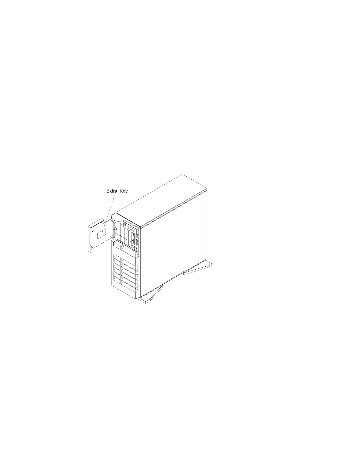
1. Open the door. If the diskette drive contains packing material or a diskette,
remove it from the drive.
2. Remove the extra key and ID tag that is taped inside the door and store them in
a secure place.
3. Turn on all external devices, such as printers, plotters, or modems.
1-6 IBM RS/6000 7025 F50 Series User's Guide
Page 25
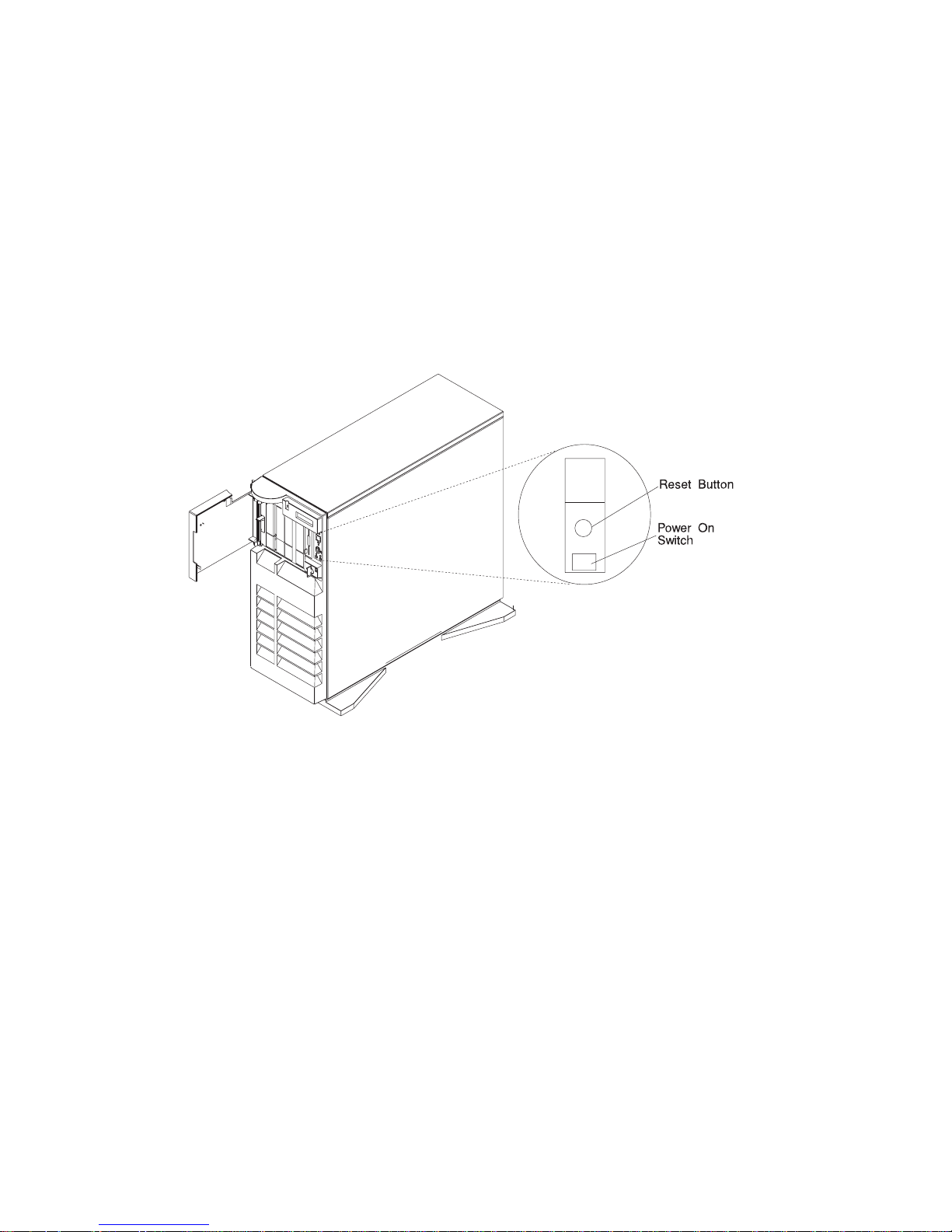
4. Press the Power On switch.
5. Check your display or ASCII terminal for configuration information displayed as
the
power-on self-test (POST)
begins. The system beeps once to indicate it is
working properly.
If no operating system is installed, you are prompted to select the operating
system installation device.
Chapter 1. System Startup 1-7
Page 26

Finishing the Installation
Important
Be sure to maintain at least 51 mm (2 in.) of space on all sides of the system
to allow the system's cooling system to work properly. Blocking the air vents
can cause overheating, which might result in a malfunction or permanent
damage.
Your system hardware is set up, and you are ready to learn about your system and
make backup copies of important software. The order in which you do these tasks is
up to you. Use the following checklist as a guide.
Ø Record your identification numbers
Your system has important identification information that you might need if you
have it serviced. Appendix A, “System Records” on page A-1 shows where to
find these numbers, and provides space to record and retain this information.
Ø Install options
If you decided earlier to delay installing your options, you might want to
complete these installations now. See Chapter 5, “Installing Options” on
page 5-1 for handling and installation instructions.
Ø Install the Operating System
If AIX is preinstalled in your system unit, or if you plan to install AIX yourself,
refer to the Quick Installation and Startup Guide for instructions.
Some options that you might install come with a diskette that contains device
drivers, configuration files, or test programs. To install these files (after your
operating system is installed), follow the instructions that come with the
diskettes.
Ø Install application programs
To install application programs, follow the instructions supplied with each
application program.
1-8
IBM RS/6000 7025 F50 Series User's Guide
Page 27

Chapter 2. Using the System Unit
Starting the System Unit
1. Set the power switches of the attached devices to On.
Note: When the system is plugged in but not powered on, the Power On LED
flashes slowly.
2. Press the Power On switch.
When you press the Power On switch, the Power On LED comes on and the
system starts a POST (power-on self test).
During POST, progress codes display in the operator panel display.
3. If the Power On light does not come on and there is no indication of power when
you press the Power On switch, ensure that the power cord, located at the back
of the system unit, is plugged into a grounded electrical outlet. If this does not
solve the problem, go to Chapter 9, “Hardware Problem Determination” on
page 9-1. If the LED is not flashing and OK is not displayed in the display, go to
the section on running the diagnostics.
Stopping the System Unit
Attention: When using the shutdown procedure for your system, enter the correct
command before you stop the system unit. Failure to do so may result in the loss of
Chapter 2. Using the System Unit 2-1
Page 28

data. If you need information on the shutdown procedure for your operating system,
see your operating system documentation.
1. Before stopping the system unit, you must first perform a shutdown procedure of
the operating system to prevent the loss of data.
2. After you shut down the operating system, set the power switches of the
attached devices to Off.
3. The system unit is powered down by the shut down procedure.
2-2
IBM RS/6000 7025 F50 Series User's Guide
Page 29

Reading the Operator Panel Display
The operator panel display is used to:
Track the progress of the system unit self tests and configuration program.
Display codes when the operating system comes to an abnormal end.
Display system messages.
During power-on self-test (POST), 4 characters display indicating the progress of the
testing. If an error is detected that requires attention, the system unit halts and an 8
digit number displays in the operator panel display to identify the error.
Chapter 2. Using the System Unit 2-3
Page 30

Using the Keyboards
There are several keyboards available for the system unit. The keyboards have
various keys that enter data and control the cursor location. The keyboards can be
engraved for the languages of different countries.
The functions of each keyboard depend on the software used. The character sets for
the keyboards are contained and explained in the information for your operating
system.
The keyboard is divided into four sections:
Function keys are multipurpose keys and their function is controlled by the
operating system.
Typewriter keys are similar to a standard typewriter. Their function is controlled
by the software.
Control keys move the cursor on the screen and do programmed control
functions. The movement and functions depend upon the application used.
Numeric keypad is arranged like a calculator to help when typing numbers.
2-4
IBM RS/6000 7025 F50 Series User's Guide
Page 31

On all of the keyboards, you can adjust the tilt position for typing comfort. To tilt the
keyboard, pull out on the keyboard legs. The legs snap into position. To decrease
the tilt of the keyboard, rotate the keyboard legs until they snap into the bottom of
the keyboard case.
The keyboard cable plugs into the keyboard connector at the rear of the system unit.
Chapter 2. Using the System Unit 2-5
Page 32

Using the Three–Button Mouse
The mouse is a hand–operated locating device. A three–button mouse is available
for use with the system unit.
Consult your application publication for the exact use of the three–button mouse.
You can use the mouse to perform such functions as positioning a cursor, selecting
items from a menu, or moving around in your document much easier and faster than
if you used only the keyboard. The cursor moves exactly as you move the mouse on
a flat surface, such as a desktop.
When you move the mouse around on a flat surface as shown in this illustration, the
cursor moves on the display screen; the movement changes the position of the
cursor.
IBM RS/6000 7025 F50 Series User's Guide
2-6
Page 33

With the mouse buttons, you can perform functions such as selecting and
deselecting options, extending your selection, or choosing a command. The precise
function of your mouse depends on the software you are using.
The mouse has a cable that plugs into the mouse connector at the rear of the
system unit.
Handling the Mouse Correctly
For best operation, handle the mouse with care. Incorrect handling can damage the
mouse.
Do not:
Operate the mouse on cloth, unfinished wood, newspaper, or carpet.
Drop or hit the mouse.
Carry the mouse by holding onto the cable.
Expose the mouse to extreme temperatures or direct sunlight.
Place the mouse in liquid spills.
Chapter 2. Using the System Unit 2-7
Page 34

Care of the Mouse
The operating surface for the mouse should be smooth, clean, and flat. For
example, you can operate the mouse on the following surfaces:
Finished wood
Glass
Enamel
Plastic
Paper (except newspaper)
Metal
Rough surfaces collect contaminants that can be transferred to the interior of the
mouse by the ball. The surface you use should be free from spills, dirt, dust, lint,
wax, eraser dust, and other foreign matter. Rough surfaces can also cause the pads
located on the bottom of the mouse to prematurely wear. A deeply pitted surface
could cause erratic operation of the mouse.
Inspect the work surface for spills or other contaminants.
Dust the work surface.
If you are using a paper pad, inspect it for wear and replace it if necessary.
2-8
IBM RS/6000 7025 F50 Series User's Guide
Page 35

Cleaning the Mouse
1. Remove the retaining ring by turning it counterclockwise, in the direction of the
arrow as shown in the illustration.
2. Remove the ball.
3. Inspect the ball for contaminants. Wipe it clean with a dry, lint–free cloth.
4. If the ball is dirty, wash it in warm, soapy water. Rinse and wipe the ball with a
lint–free cloth until dry.
5. Inspect the ball cavity in the mouse for foreign materials. If there are any foreign
materials, remove them.
6. Replace the ball.
7. Replace the retaining ring on the mouse and align it with the open slots in the
ball cavity.
8. Turn the retaining ring clockwise until the open slots are covered and you hear
the ring snap into place.
Chapter 2. Using the System Unit 2-9
Page 36

Using the 3.5–Inch Diskette Drive
Diskette Compatibility
The system unit has a 1.44MB diskette drive installed vertically in the front.
The 1.44MB diskette drive can format, read, and write diskettes compatible with the
following diskette drives:
1.0MB diskettes with 720KB formatted data capacity.
2.0MB diskettes with 1.44MB formatted data capacity (HD).
Format the diskette according to its specified capacity.
Write–Protecting 3.5–Inch Diskettes
Write–protecting diskettes is necessary so that important information is not
accidentally lost.
When diskettes are write–protected, you can read information from the diskettes, but
you cannot write information on to them.
There is a write–protect tab on the 3.5–inch diskette.
To locate the write–protect tab, turn the diskette over with the label facing down.
To prevent writing onto a diskette, slide the write–protect tab, to open the protect
slot.
2-10 IBM RS/6000 7025 F50 Series User's Guide
Page 37

To allow writing onto a diskette, slide the write–protect tab to cover the protect
slot.
Loading and Unloading the 3.5–Inch Diskette
To load a diskette into the drive, insert the diskette in the diskette drive with the
labeled metal shutter first. Push the diskette into the drive until you hear a click.
The click indicates that the diskette is securely in position in the drive.
To unload the diskette, push the diskette–unload button. The diskette unloads
partially from the drive. Pull the diskette out.
Chapter 2. Using the System Unit 2-11
Page 38

Using the CD–ROM Drive
CAUTION:
A Class 3 laser is contained in the device. Do not attempt to operate the device
while it is disassembled. Do not attempt to open the covers of the device, as it
is not serviceable and is to be replaced as a unit.
The CD–ROM is located in bay A1 of the system unit, see page 2-15. Your
CD–ROM drive looks like the one shown in the illustration, and the controls are
located as indicated.
When the CD–ROM is set to On, the status light indicates one of several conditions.
The following are status light states and the respective conditions of the CD–ROM
drive:
Off during standby with the tray loaded or unloaded.
Blinks from insertion of the tray to completion of initialization.
Blinks slowly when disc is dusty.
Blinks fast when in the audio mode.
Lights during data transfer operations.
Lights steady when:
– No disc is in the tray.
– The disc is in the tray upside down.
– Some condition exists that should be checked. If this occurs, contact your
service representative.
2-12
IBM RS/6000 7025 F50 Series User's Guide
Page 39

Loading the CD–ROM Drive
Press the unload button to open the tray. Place the disc, with the printed side away
from the tray, into the tray. Slip out the bottom tabs to hold the disc in place. Push
gently on the load/unload button. The drive automatically pulls the tray into the drive
and prepares the disc for reading.
Unloading the CD–ROM Drive
Push and hold the unload button until the drawer comes out and then remove the
disc.
Cleaning the CD–ROM Drive
This CD–ROM drive has an internal head–cleaning mechanism, and therefore does
not require an external cleaning device. The internal cleaning mechanism cleans the
head every time the tray is operated.
Always handle discs carefully by the edges to avoid leaving fingerprints or scratching
the disc. (This helps the disc to maintain good readability.) Discs can be wiped with a
soft, lint–free cloth or lens tissue. Always wipe in a straight line from the inner hub to
the outer rim.
Chapter 2. Using the System Unit 2-13
Page 40

Emergency Eject
Note: Execute the following procedure only in an emergency (tray will not eject
although pressing the unload button).
1. Insert a small diameter rod, such as a straightened paper clip, into the
emergency eject hole. (Refer to the illustration below for the location of the
emergency eject hole.)
2. Push the tool in until some resistance is felt.
3. Maintain a small amount of pressure on the rod while pulling on the tray with
your finger nail.
4. Pull the tray open and remove the disc.
Note: Normally the tray makes a ratcheting sound when pulling it open using the
above procedure.
2-14
IBM RS/6000 7025 F50 Series User's Guide
Page 41

Using the Hot Swap Disk Drives
For information on installing hot swap drives refer to “Installing a SCSI Disk Drive in
Bank C, D, or E.” on page 5-51.
For information on removing hot swap drives refer to “Removing a SCSI Disk Drive
from Bank C, D, or E” on page 5-83.
Relationship of AIX Prompts and Physical Drive Location
A SCSI adapter and a SCSI drive address can be displayed on a user display. The
AIX command lscfg list the attached devices on the system display. A SCSI adapter
and drives might be listed as:
Labels on the right side of each bank, identify the PCI Bus indicator and PCI Slot
address for the SCSI adapter attached to each bank.
Physical Slot of SCSI Adapter Bank Label
9I/P 30 - 78
8I/P 30 - 70
7P 30 - 68
6P 30 - 60
5P 10 - 78
4P 10 - 70
3P 10 - 68
2P 20 - 60
1P 20 - 58
Second Integrated SCSI Controller 30 - 58
First Integrated SCSI Controller 10 - 60
Chapter 2. Using the System Unit 2-15
Page 42

2-16 IBM RS/6000 7025 F50 Series User's Guide
Page 43

Handling Guidelines
The hot-swap disk drive is a sensitive device. Handle the hot-swap carrier and disk
drive with care.
Do not drop the disk drive or subject the drive to excessive shock.
Do not expose the disk drive to temperatures lower than -40° F (-40° C) or
higher than 158 ° F (70° C).
If drive temperature changes, allow approximately one hour of temperature
acclimatization for every 18° F (10° C) of temperature change.
Never allow moisture to condense on the drive.
Static electricity can damage your equipment. Take these precautions to avoid
static electricity damage:
– Always handle your disk drive carefully.
– Handle the drive by the edges and never touch any exposed circuitry.
– Prevent others from touching the drive.
Store the hot-swap disk drive in a protective container such as an instrument
case or in a protected area.
Failure to observe these precautions may lead to product failure, damage, and
invalidation of all warranties.
Media can take as link as 30 seconds to spin down. Make sure that there is at
least a 30 second delay before switching off the hot-swap drives for removal.
Labels
Several labels are included in your system ship group which may be attached to the
handle of the hot-swap drive. The labels may be marked in any way that the user
can easily identify the drive for removal or installation.
Chapter 2. Using the System Unit 2-17
Page 44

Disk Drive Status LED States
SCSI Disk Drives:
The following table explains the meaning of the green and
amber status LEDs and spin down button.
Status LEDs
LED or Button Status Definition
Amber On Drive spinning
Off Drive not spinning
Green On Power On
Off Power Off
Blinking Power Off/Drive identify
Spin down Depressed Spin down drive and remove power
2-18 IBM RS/6000 7025 F50 Series User's Guide
Page 45

SSA Disk Drives: The following table explains the meaning of the Power, Ready
and Check status LEDs.
Status LEDs
LED Status Definition
Power On Power On
Off Power Off
Ready On Both SSA connections good and
drive is ready
Blinking Only one SSA connection good
Flickering Drive is executing a command
Check On Disk drive failure
Self-test running
Drive in service mode
Blinking Disk drive selected
Chapter 2. Using the System Unit 2-19
Page 46

General Information for 8-mm Tape Drive
Recommendations
Use only Data Grade 8-mm tape cartridges. These cartridges are identified by
either a Data, D, or D8 marking on the data cartridge. Use of video grade
cartridges can damage the 8-mm tape drive and can void the warranty of your
8-mm tape drive, and data written on these tapes may be lost over a short period
of time.
Remove the tape cartridge from the tape drive when it is not in use, and store
the cartridge in the cartridge case.
Do not open the door on the data tape cartridge. This door covers and protects
the magnetic tape material from dirt, dust, and damage.
Avoid touching the tape since this can cause loss of data.
Keep the tape drive door closed except when loading or unloading a tape
cartridge.
Back up and then discard any tape cartridge that repeatedly produces error
messages. The error information is in the system error log.
Clean the tape path regularly according to the cleaning procedure of the 8-mm
tape drive. Use only recommended cleaning cartridges; other cleaning cartridges
can permanently damage your 8-mm tape drive.
Attention: Do not use video grade cartridges in the 8-mm tape drive. Video grade
tapes may be unreliable and may cause permanent damage to the 8-mm tape drive.
Types of 8-mm Tape Cartridges
Test Tape Cartridge: This is a specially labeled tape cartridge that is in the
media kit with the 8-mm tape drive. Use this cartridge only when checking the
operation of the drive or running diagnostics; do not use it to save programs or
data.
Data Tape Cartridge: This is a non-labeled blank tape cartridge that is in the
media kit. Use this cartridge for saving your programs or data. The same data
tape cartridge can be used in either a 2.3GB 8-mm tape drive or a 5.0GB 8-mm
tape drive.
Cleaning Tape Cartridge: Use this cartridge for cleaning the 8-mm tape path. For
more information, see “Cleaning the Tape Path on the 5.0GB 8-mm Tape Drive”
on page 2-29.
2-20
IBM RS/6000 7025 F50 Series User's Guide
Page 47

Tape Cartridge Compatibility
The 8-mm tape drive is compatible with existing 8-mm tape subsystems that comply
to the American National Standard (ANSI) X3B5/89-136, Helical-scan Digital
Computer Tape Cartridge, 8-mm for Information Exchange. Data compression
effectively increases the cartridge capacity and data transfer rate for the 5.0GB tape
cartridges.
Note: 160 meter cartridges are not processed and are automatically ejected by the
drive.
Format Modes (C=compression mode)
8-mm Tape Drive 2.3GB 2.3GB (C) 5.0GB 5.0GB (C)
2.3GB Read/Write
5.0GB Read/Write Read only Read/Write Read/Write
Setting the Write-Protect Tab on 8-mm Tape Cartridges
Setting the write-protect tab on a tape cartridge is necessary so that information is
not accidentally lost. When the write-protect tab of a tape cartridge is set (window
closed), information can be read from the tape, but cannot be written to it.
The window on the tape cartridge controls write-protection.
Chapter 2. Using the System Unit 2-21
Page 48

Environment Considerations for 8-mm Data Cartridges
Information in this section describes operating and storage conditions including
temperature, relative humidity, and maximum wet bulb data.
Attention: The manufacturer has specified a set of temperature and humidity
ranges in which the 8-mm data cartridge can operate with ease. Only regular
cleaning procedures are required when operating the cartridge within this range. The
risk of possible data loss is increased if 8-mm tape cartridges are operated, stored,
or shipped outside the temperature or humidity ranges shown in the following table.
Before using a cartridge, always let it adjust (acclimate) to the operating
environment. Do this by placing the cartridge with its container in the operating
environment for as long as it has been away from this environment or for 24 hours,
whichever is less.
Acclimation is necessary for any data cartridge that has been exposed to a different
humidity environment or a temperature change of 11°C or 20°F or more.
Operating Ranges Storage Shipping
Temperature 16°C to 32°C
(60°F to 90°F)
Relative Humidity
(non-condensing)
Maximum Wet Bulb 26°C (79°F) 26°C (79°F) 26°C (79°F)
20 to 80% 20 to 80% 5 to 80%
5°C to 32°C
(40°F to 90°F)
-40°C to 52°C
(-40°F to 125°F)
2-22 IBM RS/6000 7025 F50 Series User's Guide
Page 49

Operating in Harsh Environments
The 8-mm tape drive is ideally suited to streaming operations, as opposed to tape
movement operations involving multiple stop/starts and random searches. When the
tape is used for frequent stop and start operations, streaming movement is beneficial
and should be used whenever possible. This can be accomplished by ensuring that
any save or restore operation is the only active operation performed by a device
connected to this SCSI I/O controller.
Any tape that has been used outside the ranges specified in the table on 2-22 for an
extended period of time (50 passes in 40 hours of nonstop operation) should not be
used as an archival tape. Exposure to the environment will deteriorate the magnetic
and physical strength of the tape. Do not store important data on a tape that has
been used outside the specified ranges; transfer the data to a new tape for reliable
archiving.
8-mm Data Cartridge Erasure
Most bulk eraser devices do not have the capability to erase 8-mm data cartridges.
To properly erase an 8-mm data cartridge with a bulk eraser device, the erasure
rating must be at least 1500 oersted.
The 2.3GB and the 5.0GB 8-mm tape drives erase residual data before writing new
data on the data tape.
Tape Cartridge Data Efficiency
The 8-mm tape cartridge efficiency is defined as the amount of data that can be
stored on the cartridge. The following variables affect the amount of data that can be
stored on a tape cartridge:
Size of the data file
Number of file marks per file
File mark size used
Compatibility mode (2.3GB or 5.0GB)
Media rewrites.
Chapter 2. Using the System Unit 2-23
Page 50

Using the 5.0GB 8-mm Tape Drive
The optional 5.0GB 8-mm tape drive is a half-height device.
Status Lights
The 5.0GB 8-mm tape drive has two green status lights and one amber status light.
The on and off combinations of the status lights indicate the conditions of the 8-mm
tape drive.
Each of the International Organization for Standards (ISO) symbols located next to a
status light indicates a specific condition of the tape drive as follows:
2-24 IBM RS/6000 7025 F50 Series User's Guide
Page 51

Status Light States
The following table explains the meaning of the green and amber status lights.
Status Lights on the 5.0GB 8-mm Tape Drive
Status Ready
(green)
The power-on self-test (POST) is running or the
system has issued a Reset to the drive.
One of the following has occurred:
The power is off.
The POST has completed successfully, but
no tape cartridge has been inserted.
A tape cartridge has been inserted and the 8-mm
tape drive is ready to receive commands from the
system.
A tape cartridge has been inserted and the 8-mm
tape drive is performing a tape load or unload
operation.
The tape is in motion and the 8-mm tape drive is
busy running a device operation.
The 8-mm tape drive has detected an internal
fault that requires corrective action. If this occurs,
see the following note.
The tape path requires cleaning. Refer to
“Cleaning the Tape Path on the 5.0GB 8-mm
Tape Drive” on page 2-29.
On On On
Off Off Off or On
On Off Off or On
Off Flashing Off or On
On Flashing Off or On
Off Off Flashing
Off or On Off or
Busy
(green)
Flashing
Disturbance
(amber)
On
Note: If a fault or an error condition occurs, first try to recover by pressing the
unload button. If this does not correct the fault, switch off the power to the 8-mm
tape drive and then switch on the power to the drive. If the condition continues, call
your service representative.
Chapter 2. Using the System Unit 2-25
Page 52

Loading the 8-mm Tape Cartridge
Before loading the tape cartridge, make sure the power is on and the write-protect
tab on the tape cartridge is properly set. Refer to “Setting the Write-Protect Tab on
8-mm Tape Cartridges” on page 2-21. The tape drive loads the tape from the
cartridge and prepares it for reading and writing.
To load the 8-mm tape cartridge, do the following:
1. Grasp the edges of the 8-mm tape cartridge with the write-protect tab toward you
and the window side of the cartridge facing to the right.
2. Slide the tape cartridge into the opening on the front of the 8-mm tape drive until
the loading mechanism pulls the cartridge into the drive and the drive door
closes. The ready status light (green) goes on if the load operation was
successful.
The 8-mm tape drive is ready for data operations when the tape cartridge is inserted.
After the cartridge is inserted into the tape drive, the tape takes about 25 seconds to
load; this does not interfere with beginning the data operations.
2-26
IBM RS/6000 7025 F50 Series User's Guide
Page 53

Commands can be entered while the tape is loading. Any commands to the tape
drive start running once the tape has finished loading. Commands not requiring the
tape cartridge are run immediately.
Chapter 2. Using the System Unit 2-27
Page 54

Unloading the 8-mm Tape Cartridge
Before performing the unload operation, make sure the power to the 8-mm tape drive
is on.
To unload and eject the tape cartridge, press the unload button. The 8-mm tape
drive rewinds the tape and then ejects the tape cartridge from the tape drive.
After pressing the unload button, the following occurs:
1. The ready status light goes off.
2. The busy status light flashes during the unload operation.
3. The busy status light will goes off when the cartridge is ejected from the tape
drive.
2-28 IBM RS/6000 7025 F50 Series User's Guide
Page 55

The time required for a tape to rewind and unload is between 18 seconds and 3
minutes, depending on the position of the tape when the unload button is pushed.
If the tape cartridge cannot unload and has to be removed manually from the drive,
contact your service representative.
Cleaning the Tape Path on the 5.0GB 8-mm Tape Drive
Attention: Do not use video cleaning cartridges in the 8-mm tape drive. Video
cleaning cartridges can damage the 8-mm tape drive.
The 8-mm tape path should be cleaned either approximately every 30 hours of tape
motion or once a month, whichever occurs first. The 5.0GB 8-mm tape drive counts
the number of hours of tape motion and indicates when the tape path requires
cleaning when the lighted disturbance status light (amber) is on.
More frequent cleaning may be required if the drive is operated in a dusty
environment or in humid conditions. If the dust is allowed to accumulate, the drive
has to perform more reads and writes. This can cause data loss, and may be
prevented by regularly scheduled cleaning of the drive.
The cleaning cartridge cleans the 8-mm tape drive. If you attempt to use an 8-mm
cleaning cartridge more times than allowed, the tape drive automatically detects the
error and ejects the cleaning cartridge. The disturbance status light (amber) remains
on if it was on prior to the cleaning operation being attempted.
Some video cleaning cartridges are extremely abrasive. An 8-mm tape drive may be
permanently damaged after only a few cleaning operations using an abrasive-type
cleaning cartridge.
Before loading the cleaning cartridge, make sure the power to the 8-mm tape drive is
on.
To load the 8-mm cleaning cartridge, do the following:
1. Grasp the edges of the 8-mm cleaning cartridge with the window side of the
cartridge facing to the right.
2. Slide the cleaning cartridge into the opening on the front of the 8-mm tape drive
until the loading mechanism pulls the cartridge into the drive.
Chapter 2. Using the System Unit 2-29
Page 56

After the 8-mm cleaning cartridge has been fully inserted into the 8-mm tape drive,
the following cleaning operations are performed automatically:
1. The cleaning tape is loaded into the tape path.
2. The drive is cleaned by moving the cleaning tape forward for approximately two
minutes.
3. The tape is unloaded and the cleaning cartridge is ejected from the tape drive
when the cleaning operation is complete.
4. A successful cleaning operation is indicated when the disturbance status light
(amber) goes off.
2-30
IBM RS/6000 7025 F50 Series User's Guide
Page 57

General Information for 4.0GB 4-mm Tape Drive
The 4.0GB 4-mm tape drive is a streaming tape drive that is used to:
Save and restore system data files.
Archive important records.
Distribute operating system software upgrades.
The 4-mm tape drive can be attached to any system using a single-ended interface
meeting the Small Computer System Interface ll (SCSI-ll) Standard ANSI
X3.131-199X Rev. 10h.
The 4-mm tape drive has the following features:
Capacity of 4.0 GB per cartridge. 8 GB is typical with data compression and with
DDS2 data cartridges.
The actual capacity per cartridge varies depending on the application and the
type of data cartridge being used.
Data transfer rate is 400 KBps. 800 KBps is typical with data compression.
Note: Data compression activated is the default setting from the factory. Data
compression is usually controlled by the application software.
Read and write of DDS|||| tape cartridges in 2.0 GB per cartridge format.
A status light that indicates when it is time to clean the tape path.
Internal diagnostics that are activated when the 4 mm Diagnostic Cartridge is
inserted and loaded into the drive.
Media recognition system: only data grade media can be written with this tape
drive.
The 4-mm tape drive uses a 4-mm data cartridge for saving and restoring your
system data. The 4-mm tape drive writes and reads only 4-mm Digital Data Storage
(DDS|||| or DDS2) cartridges.
Chapter 2. Using the System Unit 2-31
Page 58

Recommendations
Attention: Tape cartridges that do not carry the proper DDS symbol cannot be
written to and their use may cause the 4-mm tape drive to report an error.
Use only 4-mm Digital Data Storage (DDS|||| or DDS2) cartridges.
Attention: Use of other than recommended cleaning cartridges can damage
your tape drive and will void the drive warranty.
Clean the tape path by using the recommended cleaning cartridge. Follow the
instructions on the cartridge.
Back up and then discard any tape cartridge that repeatedly produces error
messages. The error information is in the system error log.
Do not open the door on the data cartridge that covers the tape. This door
protects the magnetic tape material from dirt, dust, and damage.
Do not operate in a dusty environment.
Do not touch the tape material. Any substance transferred to the tape by
touching it could cause loss of data.
Types of 4-mm Tape Cartridges
The 4-mm tape drive is shipped with three 4-mm cartridges to help start your tape
operations immediately.
4-mm Data Cartridge: Use this non-labeled cartridge for saving or
restoring your programs or data. Additional data
cartridges can be ordered.
4-mm Diagnostic Cartridge: Use this specially labeled cartridge to perform
diagnostics on the drive. Do not use it to save or
restore programs or data.
Cleaning Cartridge: Use this cartridge for cleaning the 4-mm tape path.
For more information, see “Cleaning the Tape Path
on the 4.0GB 4-mm Tape Drive” on page 2-41.
2-32
IBM RS/6000 7025 F50 Series User's Guide
Page 59

Tape Cartridge Compatibility
The 4-mm Tape Drive is compatible with existing 4mm tape subsystems that are
designed to operate with Digital Data Storage approved media, which meet the
following standards:
For DDS||||
– American National Standard (ANSI) standard, X3.203-191, Helical-scan
Digital Computer Tape Cartridge, 3.81mm.
– European Computer Manufacturers Association (EMCA) standard,
EMCA-150 , 3.81mm Wide Magnetic Tape Cartridge and DDS|||| format.
For DDS2
– European Computer Manufacturers Association (EMCA) standard,
EMCA/TC17/93/20, 3.81mm Wide Magnetic Tape Cartridge for Information
Interchange Helical Scan Recording, DDS2 format.
You cannot change the density setting of the drive, because the device reconfigures
itself automatically, depending on the media type installed, as follows:
Media Type Device Configuration
Non-DDS Read-only
DDS|||| Read/write in 2.0GB mode only.
DDS2 Read in either density; write in 4.0GB mode only.
Chapter 2. Using the System Unit 2-33
Page 60

Setting the Write-Protect Tab on 4-mm Tape Cartridges
The window on the tape cartridge controls write-protection. When the write-protect
tab of a tape cartridge is set (window open), information can be read from the tape,
but cannot be written to it. When the write-protect tab of a tape cartridge is not set
(window closed), information can be both written to and read from the tape. Trying to
write to a 4-mm data cartridge with the window open causes an error.
2-34 IBM RS/6000 7025 F50 Series User's Guide
Page 61

Environmental Considerations for 4-mm Data Cartridges
Information in this section describes operating and storage conditions including
temperature, relative humidity, and maximum wet bulb data.
Attention: The manufacturer has specified a set of temperature and humidity
ranges in which the 4-mm data cartridge can operate with ease. Only regular
cleaning procedures, as described in “Cleaning the Tape Path on the 4.0GB 4-mm
Tape Drive” on page 2-41 are required when operating the cartridge within this
range. The risk of possible data loss is increased if 4-mm tape cartridges are
operated, stored, or shipped outside the temperature or humidity ranges shown in
the following table.
Before using a cartridge, always let it adjust (acclimate) to the operating
environment. Do this by placing the cartridge with its container in the operating
environment for as long as it has been away from this environment or for 24 hours,
whichever is less.
Acclimation is necessary for any data cartridge that has been exposed to a different
humidity environment or a temperature change of 11°C or 20°F or more.
Operating Ranges Storage Shipping
Temperature 16°C to 32°C
(60°F to 90°F)
Relative Humidity
(non-condensing)
Maximum Wet Bulb 26°C (79°F) 26°C (79°F) 26°C (79°F)
20 to 80% 20 to 80% 5 to 80%
5°C to 32°C
(40°F to 90°F)
-40°C to 52°C
(-40°F to 125°F)
Chapter 2. Using the System Unit 2-35
Page 62

Operating in Harsh Environments
The 4-mm tape drive is ideally suited to streaming operations, as opposed to tape
movement operations involving multiple stop/starts and random searches. When the
tape is used for frequent stop and start operations, streaming movement is beneficial
and should be used whenever possible. This can be accomplished by ensuring that
any save or restore operation is the only active operation performed by a device
connected to this SCSI I/O controller.
Any tape that has been used outside the ranges specified in the previous table for an
extended period of time (50 passes in 40 hours of nonstop operation) should not be
used as an archival tape. Exposure to the environment will deteriorate the magnetic
and physical strength of the tape. Do not store important data on a tape that has
been used outside the specified ranges; transfer the data to a new tape for reliable
archiving.
4-mm Data Cartridge Erasure
Most bulk eraser devices do not have the capability to erase 4-mm data cartridges.
To properly erase an 4-mm data cartridge with a bulk eraser device, the erasure
rating must be at least 2000 oersted.
The 4-mm tape drive erases residual data before writing new data on the data tape.
Tape Cartridge Data Capacity
The 4-mm tape cartridge capacity is defined as the amount of data that can be
stored on the cartridge. The following variables affect the amount of data that can be
stored on a tape cartridge:
Size of the data file
Number of file marks per file
Compatibility mode (2GB or 4GB)
Media rewrites.
2-36
IBM RS/6000 7025 F50 Series User's Guide
Page 63

Using the 4.0GB 4-mm Tape Drive
The optional 4.0GB 4-mm tape drive is a half-high device.
Status Lights
The 4.0GB 4-mm tape drive has two green status lights and one amber status light.
The on and off combinations of the status lights indicate the conditions of the 4-mm
tape drive.
Each of the International Organization for Standards (ISO) symbols located over a
status light indicates a specific condition of the tape drive as follows:
Chapter 2. Using the System Unit 2-37
Page 64

Status Light States
The following tables explain the meaning of the green and amber status lights.
Ready (green) Read-Write (green) Disturbance (amber)
Off No cartridge installed or
error condition
Steady Cartridge installed or
loading/unloading
Flashing Power-on self- test in
progress
Status Lights on the 4.0GB 4-mm Tape Drive
Status Ready
LED test. On 2
The power-on self-test (POST) is running or the
Diagnostic Cartridge is running.
One of the following has occurred:
The power is off.
The POST has completed successfully, but
no tape cartridge has been loaded.
A tape cartridge has been inserted and the 4-mm
Tape Drive is Ready to receive commands from
the system.
The tape is in motion and the 4-mm Tape Drive is
running a device operation or cleaning.
The 4-mm Tape Drive has detected an internal
error that requires corrective action such as tape
cartridge failure, high humidity, or no SCSI
terminator. Refer to the service guide or contact
your service representative. (See note below)
The tape path requires cleaning or a poor quality
tape cartridge is being used. See “Cleaning the
Tape Path on the 4.0GB 4-mm Tape Drive” on
page 2-41.
No cartridge or no activity No error condition
Cleaning required or worn
media
Cartridge activity Error condition
Read-Write
(green)
seconds at
power on
Flashing Off Off
Off Off Off or On
On Off Off or ON
On Flashing Off or On
Off Off Flashing
Off or On Off or
(green)
On 2
seconds at
power on
Flashing
Disturbance
(amber)
On 2
seconds at
power on
On
Note: If an error condition occurs, first try to recover by pressing the unload button.
If this does not correct the error, switch off the power to the 4-mm tape drive and
then switch on the power to the drive. If the condition continues, call your service
representative.
2-38 IBM RS/6000 7025 F50 Series User's Guide
Page 65

Loading the 4-mm Tape Cartridge
Before loading the tape cartridge, make sure the power is on and the write-protect
switch on the tape cartridge is properly set. Refer to “Setting the Write-Protect Tab
on 4-mm Tape Cartridges” on page 2-34. The tape drive loads the tape from the
cartridge and prepares it for reading and writing.
To load the 4-mm tape cartridge, do the following:
1. Grasp the edges of the 4-mm tape cartridge with the write-protect tab towards
you and the window side of the cartridge facing up.
2. Slide the tape cartridge into the opening on the front of the 4-mm tape drive until
the loading mechanism pulls the cartridge into the drive and the drive door
closes. The ready status light (green) goes on if the load operation was
successful.
The 4-mm tape drive is ready for data operations when the tape cartridge is inserted.
After the cartridge is inserted into the tape drive, the tape takes about 15 seconds to
load.
Chapter 2. Using the System Unit 2-39
Page 66

Unloading the 4-mm Tape Cartridge
Before performing the unload operation, make sure the power to the 4-mm tape drive
is on.
To unload and eject the tape cartridge, press the unload button. The 4-mm tape
drive rewinds the tape and then ejects the tape cartridge from the tape drive.
After pressing the unload button, the following occurs:
1. The Read-Write status light flashes during the unload operation.
2. The Ready status light and the Read-Write status light turns off when the
cartridge is ejected from the tape drive.
The time required for a tape to rewind and unload is between 10 seconds and 1.5
minutes, depending on the position of the tape when the unload button is pushed.
If the tape cartridge cannot unload and has to be removed manually from the drive,
contact your service representative.
2-40 IBM RS/6000 7025 F50 Series User's Guide
Page 67

Cleaning the Tape Path on the 4.0GB 4-mm Tape Drive
The 4-mm tape path should be cleaned either approximately every 30 hours of tape
motion or once a month, whichever occurs first. The 4-mm tape drive monitors the
recording quality of the tape cartridge and indicates that the tape path requires
cleaning when the disturbance status light (amber) is on.
More frequent cleaning may be required if the drive is operated in a dusty
environment or in humid conditions. If the dust is allowed to accumulate, the drive
has to perform more reads and writes. This can cause data loss, and may be
prevented by regularly scheduled cleaning of the drive.
The cleaning cartridge cleans the 4-mm tape drive 50 times before it needs to be
discarded. If you attempt to use a 4-mm cleaning cartridge more than 50 times, the
tape drive automatically detects the error and ejects the cleaning cartridge with the
disturbance status light (amber) remaining on.
Before loading the cleaning cartridge, make sure the power to the 4-mm tape drive is
on.
To load the 4-mm cleaning cartridge, do the following:
1. Grasp the edges of the 4-mm cleaning cartridge with the window side of the
cartridge facing up.
2. Slide the cleaning cartridge into the opening on the front of the 4-mm tape drive
until the loading mechanism pulls the cartridge into the drive.
After the 4-mm cleaning cartridge has been fully inserted into the 4-mm tape drive,
the following cleaning operations are performed automatically:
1. The cleaning tape is loaded into the tape path.
Chapter 2. Using the System Unit 2-41
Page 68

2. The drive is cleaned by moving the cleaning tape forward for approximately 30
seconds.
3. The tape is unloaded and the cleaning cartridge is ejected from the tape drive
when the cleaning operation is complete.
4. A successful cleaning operation is indicated when the disturbance status light
(amber) goes off (if it was activated before the cleaning operation).
If the cleaning cartridge has been used more than 50 times the disturbance status
light (Amber) will flash.
2-42 IBM RS/6000 7025 F50 Series User's Guide
Page 69

Chapter 3. System Management Services
The System Management Services make it possible for you to view information
about your computer and to perform such tasks as setting passwords and changing
device configurations.
If you have chosen a graphical display as your system console, you can use the
graphical System Management Services described below. If you are using an ASCII
display as your system console, see “Text-Based System Management Services” on
page 3-24.
Graphical System Management Services
To start the Open Firmware command line or graphical System Management
Services, turn on or restart the computer.
After the logo is displayed, initialization icons appear across the bottom of the
screen.
To enter the Open Firmware command line, you must press the F8 key
keyboard icon appears
If you have pressed the F8 key, the Open Firmware command line (an "OK" prompt)
appears after the initialization and power-on self test (POST) are complete.
The Open Firmware command line is used to set up adapters that are not
configurable with the System Management Services. Your adapter documentation
directs you to use this option if it is needed.
To exit from the Open Firmware command enter reset-all or power the system
down and reboot.
during startup.
after the
Chapter 3. System Management Services 3-1
Page 70

To enter the graphical System Management Services instead of the Open Firmware
command line, you must press the F1 key
after the keyboard icon appears
during
startup.
After the System Management Services starts, the following screen appears.
You may also press F8 here to enter the OK> prompt.
IBM RS/6000 7025 F50 Series User's Guide
3-2
Page 71

The System Management Services screen contains the following choices.
Config: Enables you to view your system configuration.
MultiBoot: Invokes the Mulitboot menu which provides several
functions:
To Select a particular operating system to boot.
In the case of AIX this is a supported option, if you receive
a an informational icon after making this selection this
would mean that information in non-volatile storage could
have been lost, as would happen if the battery had been
removed. In order to recreate this value, issue the bootlist
command under AIX with the appropriate parameters as to
the location of the operating system in a particular hard
disk. Please see the explanation of the bootlist command
in your AIX documentation.
To select a particular operating system as the default
operating system
To install from the list of possible devices
To set the sequence in which devices are searched for
To go to the Open Firmware command prompt
To set the Multiboot menu so that it comes up immediately
Utilities: Enables you to set and remove passwords, enable
the unattended start mode, set and view the addresses of your
system's SCSI controllers, select the active console, view or
clear the error log, and update your system firmware.
Exit: Returns you to the previous screen.
Chapter 3. System Management Services 3-3
operating system startup code
as the system powers up
Page 72

To select an icon, move the cursor with the arrow keys to choose which icon is
highlighted, then press the Enter key. You can also select an icon by clicking on it
with your left mouse button. To leave the current screen, either press the Esc key or
select the Exit icon.
3-4 IBM RS/6000 7025 F50 Series User's Guide
Page 73
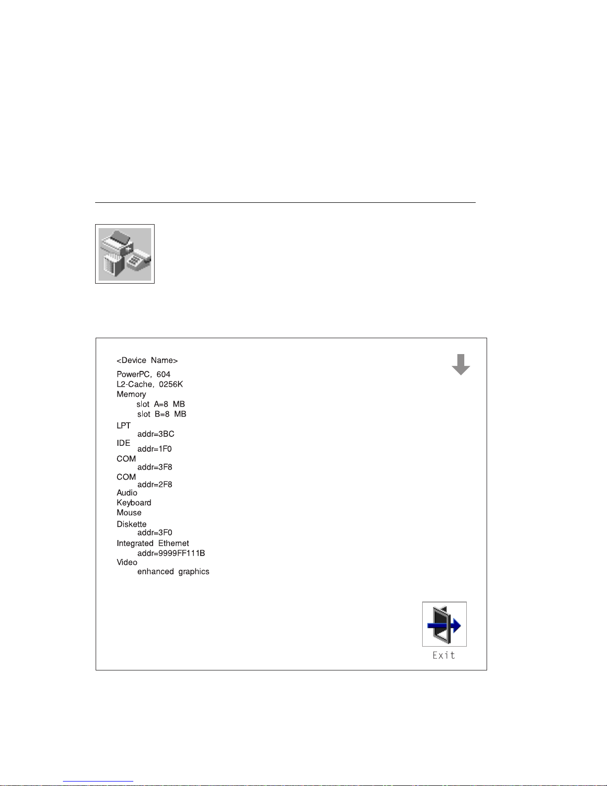
Config
Selecting this icon makes it possible for you to view information about the setup of
your system unit. A list similar to the following appears when you select the Config
icon.
Chapter 3. System Management Services 3-5
Page 74

Selecting the down arrow key or Page Down key displays the next configuration
screen, which lists your computer's firmware version, the date of its development,
and the firmware part number.
The following screen is provided by the service processor.
3-6 IBM RS/6000 7025 F50 Series User's Guide
Page 75

MultiBoot:
This selection invokes the Mulitboot menu which provides several functions:
To Select a particular operating system to boot.
In the case of AIX this is a supported option, if you receive a an informational
icon after making this selection this would mean that information in non-volatile
storage could have been lost, as would happen if the battery had been removed.
In order to recreate this value, issue the bootlist command under AIX with the
appropriate parameters as to the location of the operating system in a particular
hard disk. Please see the explanation of the bootlist command in your AIX
documentation.
To select a particular operating system as the default operating system
To install from the list of possible devices
To set the sequence in which devices are searched for operating system startup
code
To go to the Open Firmware command prompt
To set the Multiboot menu so that it comes up immediately as the system powers
up
The Select Software option, if supported by the operating system, shows the names
of the operating system installed. This option may not be supported by all operating
systems.
In the case of AIX this is a supported option, if you receive a message saying that:
No Operating System Installed
Chapter 3. System Management Services 3-7
Page 76

this would mean that information in non-volatile storage could have been lost, as
would happen if the battery had been removed. In order to recreate this value issue
the bootlist command under AIX with the appropriate parameters as to the location of
the operating system in a particular Hard disk. Please see the explanation of the
bootlist command in your AIX documentation.
The Software Default option, if supported by the operating system, lets you select the
default operating system to start the system. This option may not be supported by
all operating systems.
The Install From option produces a list of devices, for example the CD-ROM, where
the operating system is installed from. You select one of the devices and the system
searches the device for an operating system to install and if supported by the
operating system in that device, the name of the operating system displays.
The Select Boot Device option provides a list of devices that can be selected to be
stored on the boot list. Up to 5 devices are supported.
The OK Prompt procvides access to the Open Firmware command prompt. The
Open Firmware command prompt is used for debug purposes, and device driver
development. Information about the commands that are available in the IEEE
Standard 1275.
The Multiboot Start option toggles between OFF and ON and selects if the Multiboot
menu invokes automatically on startup or not.
Boot
This selection enables you to view and change the custom boot list (the sequence in
which devices are searched for operating system startup code).
3-8
IBM RS/6000 7025 F50 Series User's Guide
Page 77

Attention: If you change your startup sequence, you must be extremely careful
when performing
write
operations (for example, copying, saving, or formatting). You
can accidentally overwrite data or programs if you select the wrong drive.
The default boot sequence is:
The primary diskette drive
CD-ROM drive
Tape id=5 (slot=1)
Hard disk drive id=6 (Slot=1)
Network device.
To change the custom boot list, enter a new order in the New column, then select
Save. The List of Boot Devices is updated to reflect the order you have chosen.
You can choose 1 to 5 devices for the custom boot list. To change the boot
sequence back to the default values, select Default. (The default sequence is
automatically saved.)
Chapter 3. System Management Services 3-9
Page 78

Utilities
Selecting this icon enables you to perform various tasks and view additional
information about your computer.
The following describes the choices available on this screen.
Password: Enables you to set password protection for turning
on the computer and for using system administration tools.
Error Log: Enables you to view and clear error log information
for your computer.
RIPL (Remote Initial Program Load): Allows you to select a
remote system from which to load programs via a network
adapter when your system unit is first turned on. This option
also allows you to configure network adapters which require
setup.
3-10
IBM RS/6000 7025 F50 Series User's Guide
Page 79

Update: Allows you to update the firmware programs on your
computer.
Console: If you have more than one display attached to your
system unit, or if you have an ASCII terminal attached to your
system unit in addition to a keyboard and display, this tool
allows you to define which one is active.
Chapter 3. System Management Services 3-11
Page 80

Password
When you select this icon, the following screen is displayed.
Power-On Password: Setting a power-on password helps protect information stored
in your computer. If a power-on password is set for your computer, the Power On
icon is shown in the locked position; if a power-on password is not set, then the
Power On icon is shown in the unlocked position (as in the screen above).
When you select the Entry icon, a screen with 8 empty boxes appears. Type your
password in these boxes. You can use any combination of up to eight characters
(A–Z, a–z, and 0–9) for your password. As you type a character, a key appears in
the box.
3-12 IBM RS/6000 7025 F50 Series User's Guide
Page 81

Press Enter when you are finished; you are required to type the password again for
verification.
If you make a mistake, press the Esc key and start again.
After you have entered and verified the password, the power-on password icon
flashes and changes to the locked position to indicate that the power-on password is
set.
If you previously had set a power-on password and want to remove it, select the
Remove icon.
Note: If you
forget
the power-on password, you have to remove the battery for at
least 30 seconds to disable this password. See Appendix B, “Replacing the
Battery” on page B-1 for details.
Attention: After you remove the battery, you must reconfigure your system (bootlist,
IP parameters, console information, support processor, etc).
A password can be set only after the system is turned off and on again.
Chapter 3. System Management Services 3-13
Page 82

Remote Mode: The remote mode, when enabled, allows the system to start from
the defined boot device. This mode is ideal for network servers and other computers
that operate unattended. You
must
set a power-on password before you can enable
the remote mode. When the remote mode is set, the icon changes to Remote
<On>.
If you remove the power-on password, the remote mode is automatically reset, and
the icon returns to Remote <Off>.
Privileged-Access Password: The privileged-access password protects against the
unauthorized starting of the system programs.
When you select the Entry icon, a screen with 8 empty boxes appears. Type your
password in these boxes. You can use any combination of up to eight characters
(A–Z, a–z, and 0–9) for your password. As you type a character, a key appears in
the box.
Press Enter when you are finished; you are required to type the password again for
verification.
If you make a mistake, press the Esc key and start again.
3-14
IBM RS/6000 7025 F50 Series User's Guide
Page 83

After you have entered and verified the password, the privileged-access password
icon flashes and changes to the locked position to indicate that your computer now
requires the password you just entered before running system programs.
Note: If you
least 30 seconds to disable this password. See Appendix B, “Replacing the
Battery” on page B-1 for details.
forget
the power-on password, you have to remove the battery for at
Chapter 3. System Management Services 3-15
Page 84

Error Log
Selecting this icon displays the log of errors your computer has encountered during
operations.
Selecting the Clear icon erases the entries in this log.
3-16
IBM RS/6000 7025 F50 Series User's Guide
Page 85

RIPL
Selecting the Remote Initial Program Load (RIPL) icon above gives you access to
the following selections.
Chapter 3. System Management Services 3-17
Page 86

The Set Address icon allows you to define addresses from which your computer can
receive RIPL code.
Notes:
1. Some applications may require that IP addresses contain leading zeroes for
numbers less than 100. For example, 129.132.4.20 may need to be entered as
123.132.004.020.
If any of the addresses is incomplete or contains a number other than 0 to 255, an
error message is displayed when you select the Save icon. To clear this error,
change the improper address and select Save again.
Note: You should save a copy of your changes in case you need to replace your
battery.
3-18
IBM RS/6000 7025 F50 Series User's Guide
Page 87

The Ping icon allows you to confirm that a specified address is valid by sending a
test transmission to that address.
After choosing the Ping option, you may be asked to indicate which communications
adapter (Token Ring or Ethernet) should be used to send the test transmission.
Chapter 3. System Management Services 3-19
Page 88

The Config icon allows you to configure network adapters which require setup.
Selecting the Config icon presents a list of the adapters requiring configuration. Use
the arrow keys to highlight an adapter, press the spacebar to select the adapter, then
highlight the OK icon and press the Enter key.
The next screen allows you to select the configuration of the adapter you have just
chosen (or allow the system to select the configuration automatically). As on the
previous screen, use the arrow keys to highlight, press the space bar to select, then
highlight the OK icon and press enter.
3-20
IBM RS/6000 7025 F50 Series User's Guide
Page 89

SCSI ID
This selection allows you to view and change the addresses (IDs) of the SCSI
controllers attached to your system unit. To change an ID, highlight the entry by
moving the arrow keys, then use the space bar to scroll through the available ID's.
After you have entered the new address, use the arrow keys to highlight the Save
icon and press the Enter key.
At any time in this process, you can select the Default icon to change the SCSI IDs
to the default values.
Chapter 3. System Management Services 3-21
Page 90

Update
This selection allows you to update the service processor and system firmware in
your system unit from an image on a 3.5 inch diskette. After choosing to update the
firmware and confirming this choice, you must insert the diskette containing the
firmware image.
ATTENTION: While the new firmware image is being copied into your system unit,
you must not turn off the system unit. Turning off the system unit during the
update process may render your system unit inoperable.
After the flash update is complete, the system unit restarts.
If the flash update does not complete successfully or the system unit does not restart
after the flash update, contact your authorized reseller or marketing representative.
3-22
IBM RS/6000 7025 F50 Series User's Guide
Page 91

Firmware Recovery
If a troubleshooting procedure has indicated that the firmware information in your
system unit has been corrupted, then you must perform a firmware recovery.
To perform a firmware recovery, do the following:
1. Locate your firmware update diskette.
2. Using another system unit, rename the
*.img ,br file on the firmware update diskette to
precover.img
3. Make sure your system unit is turned off.
4. Insert the firmware recovery diskette into your system unit.
5. Turn on your system unit.
6. When the keyboard indicator appears, press the 1 key if the system console is
an ASCII terminal, or the F1 key if the system console is a directly-attached
keyboard.
7. When the System Management Services appear, choose Utilities and perform a
Firmware Update as described above.
Chapter 3. System Management Services 3-23
Page 92

Text-Based System Management Services
The text-based Open Firmware command line and System Management Services are
available if an ASCII terminal is attached to your system unit. The text-based Open
Firmware command line allows you to configure some adapters, and the System
Management Services makes it possible for you to view information about your
system unit and to perform such tasks as setting passwords and changing device
configurations.
To enter the Open Firmware command line, you must press the 8 key
keyboard text symbol appears
during startup.
after the
If you have pressed the 8 key, the Open Firmware command line (an "OK" prompt)
appears after the initialization and power-on self tests (POST) are complete.
The Open Firmware command line can be used to set up adapters that are not
configurable with the System Management Services. Your adapter documentation
directs you to use this option if it is needed.
To exit from the Open Firmware command enter reset-all or power the system
down and reboot.
To start the text-based System Management Services instead of the Open Firmware
command line, press 1 on the ASCII terminal keyboard when the keyboard text
symbol appears during startup.
3-24
IBM RS/6000 7025 F50 Series User's Guide
Page 93

After the text-based System Management Services starts, the following screen
appears.
à ð
System Management Services
1. Display Configuration
2. Multiboot
3. Utilities
4. Select Language
.------.
|X=Exit|
------'
====>
á
ñ
Selecting the numbered options provide capabilities described on the following
pages.
After you have finished using the text-based System Management Services, entering
x (for exit) boots your computer.
Chapter 3. System Management Services 3-25
Page 94

Display Configuration
This option provides information about the setup of your computer. A screen similar
to the following is displayed.
à ð
Device
PowerPC 64
L2-Cache, 512K
Memory
slotA=8MB
slotB=8MB
LPT
addr=3BC
COM
addr=3F8
COM
addr=2F8
Audio
Keyboard
Mouse
Diskette
addr=3F
Integrated Ethernet
addr=85AF67BD
SCSI cntlr id=7
PCI Adapters
.-----------. .-----------. .------.
|P=prev-page| |N=next-page| |x=Exit|
-----------' -----------' ------'
á
Note that this configuration information does not include ISA adapters installed in the
system unit.
3-26
IBM RS/6000 7025 F50 Series User's Guide
ñ
Page 95

MultiBoot Menu
à ð
Multiboot Menu
1. Select Software
2. Software Default
3. Install From
4. Select Boot Devices
5. OK Prompt
6. Mulitboot Startup <OFF> (or <ON>)
.------.
|X=Exit|
------'
===>
á
ñ
The Select Software option, if supported by the operating system, shows the names
of the operating system installed. This option may not be supported by all operating
systems.
In the case of AIX this is a supported option, if you receive a message saying that:
No Operating System Installed
this would mean that information in non-volatile storage could have been lost, as
would happen if the battery had been removed. In order to recreate this value issue
the bootlist command under AIX with the appropriate parameters as to the location of
the operating system in a particular Hard disk. Please see the explanation of the
bootlist command in your AIX documentation.
The Software Default option, if supported by the operating system, lets you select the
default operating system to start the system. This option may not be supported by
all operating systems.
The Install From option produces a list of devices, for example the CD-ROM, where
the operating system is installed from. You select one of the devices and the system
searches the device for an operating system to install and if supported by the
operating system in that device, the name of the operating system displays.
The Select Boot Device option provides a list of devices that can be selected to be
stored on the boot list. Up to 5 devices are supported.
Chapter 3. System Management Services 3-27
Page 96

The OK Prompt procvides access to the Open Firmware command prompt. The
Open Firmware command prompt is used for debug purposes, and device driver
development. Information about the commands that are available in the IEEE
Standard 1275.
The Multiboot Start option toggles between OFF and ON and selects if the Multiboot
menu invokes automatically on startup or not.
Select Boot Devices
This selection enables you to view and change the custom boot list, which is the
sequence of devices read at startup time.
à ð
Select Boot Devices
1. Display Current Settings
2. Restore Default Settings
3. Configure 1st Boot Device
4. Configure 2nd Boot Device
5. Configure 3rd Boot Device
6. Configure 4th Boot Device
7. Configure 5th Boot Device
.------.
|X=Exit|
------'
====>
á
Selecting the Display Current Settings option lists the current order of devices in the
boot list. The following screen shows an example of this display.
3-28
IBM RS/6000 7025 F50 Series User's Guide
ñ
Page 97

à ð
Current Boot Sequence
1. Diskette
2. Ethernet (Integrated)
3. SCSI CD-ROM id=3 (slot=1)
4. SCSI 5MB Hard Disk id=6 (slot=1)
5. SCSI 5MB Hard Disk id=5 (slot=5)
.------.
|X=Exit|
------'
===>
á
ñ
Chapter 3. System Management Services 3-29
Page 98

Selecting any of the Configure Boot Device options displays the following screen.
à ð
Configure Nth Boot Device
Device Number Current Position Device Name
1 1 Diskette
2 2 Ethernet
3 3 SCSI CD-ROM
5 -
.-----------. .-----------. .------.
|P=prev-page| |N=next-page| |X=Exit|
-----------' -----------' ------'
===>
4 4 SCSI 4.5GB Hard Disk
á
ñ
3-30 IBM RS/6000 7025 F50 Series User's Guide
Page 99

Utilities
The Utilities screen enables you to select from the following system management
tools.
à ð
Utilities
1. Set Password and Unattended Start Mode
2. Audio <ON>
3. Display Error Log
4. Remote Initial Program Load Setup
5. Change SCSI id
6. Update System Firmware
7. Update Service Processor
8. Select Console
.------.
|X=Exit|
------'
===>
á
ñ
Set Password and Unattended Start Mode: Entering this selection permits
access to the following options.
à ð
Password Utilities
1. Set Power On Password
2. Remove Power On Password
3. Unattended Start Mode <OFF>
4. Set Privileged-Access Password
5. Remove Privileged-Access Password
.------.
|X=Exit|
------'
===>
á
ñ
Chapter 3. System Management Services 3-31
Page 100

Set Power On Password: Setting a power-on password helps protect information
stored in your computer. You can use any combination of up to eight characters
(A–Z, a–z, and 0–9) for your password. The password you type is not displayed on
the screen. Press Enter when you are finished; you are required to type the
password again for verification.
If you previously had set a power-on password and wanted to remove it, select
Remove Power-On Password.
forget
Note: If you
your password, you have to shut down the computer and
remove the battery for at least 30 seconds to disable the password. See
Appendix B, “Replacing the Battery” on page B-1 for details.
A password can be set only after the system is turned off and on again.
3-32
IBM RS/6000 7025 F50 Series User's Guide
 Loading...