

Page 1
8271 N
WAYS
E
THERNET
LAN S
WITCH
M
ODELS
F12
AND
F24
Q
UICK
R
EFERENCE
G
UIDE
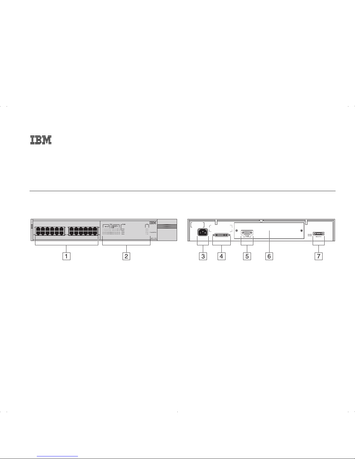
Hardware Features
The Illustration shows a Switch Model F24
(02L0879). The port and LED layout is different for a
Switch Model F12 (02L0878).
1
10BASE-T/100BASE-TX Ports
These auto-negotiating ports can automatically detect the speed of a
link and provide a 10Mbps connection to Ethernet
devices or a 100Mbps connection to Fast Ethernet
devices. The ports are configured as MDIX
(cross-over) and support a maximum segment length
of 100m (328ft) over Category 5 twisted pair cable.
2
Status LEDs
These LEDs provide a quick method of
diagnosing problems. See “LEDs” for more information.
3
Power Socket
Insert the power cord into this
socket to connect the Switch to the main power
supply. Note that there is no On/Off button.
4
Redundant Power System Socket
Use this socket
to connect an Advanced Redundant Power System
(RPS) to the Switch, and therefore protect against
internal power supply failure.
5
Console Port
Use this port to connect a terminal or
terminal emulator to the Switch, and therefore allow
out-of-band management.
The console port uses
standard null modem cable and is set to
auto-baud, 8 data bits, no parity and 1 stop bit.
6
Expansion Module Slot
Remove the blanking plate
to install an optional Expansion Module that provides an additional high-speed link, or a Matrix
Module that provides four matrix ports for stacking
Switch units together.
7
Matrix Port
Use this port to connect a Matrix
Cable, which allows you to stack Switch units
together.
Page 2

LEDs
Default Settings
Default Passwords
LED Color Indicates
Port Status LEDs
Packet
Yellow Packets are being transmitted/received on the
port.
Off No packets are being transmitted/received on
the port.
Status
Green A link is present, and the port is enabled.
Green
flashing
A link is present, but the port is disabled.
Off No link is present.
Expansion Module Port Status LEDs
Packet
Yellow Packets are being transmitted/received on the
Expansion Module port(s).
Off No packets are being transmitted/received on
the Expansion Module port(s).
Status
Yellow A valid Expansion Module is installed in the
Switch.
Yellow
flashing
An unrecognized Expansion Module is installed
in the Switch.
Off No Expansion Module is installed in the Switch.
Unit LEDs
1 – 8
Green
Indicates the position of the Switch in the
stack and that a link is present. Note that
although there are eight LEDs, only four
Switch units can be stacked at present.
1 – 8
Off
The Switch is stand-alone.
LED Color Indicates
Power/Self Test LED
Green The Switch is powered-up.
Green
flashing
The Switch is either downloading software or
is initializing (which includes running a Power
On Self Test).
Yellow The Switch has failed its Power On Self Test.
Off The Switch is not receiving power.
Port Status
Enabled
Port Speed
10BASE-T/100BASE-TX ports are
auto-negotiated
Duplex Mode
All fixed ports are auto-negotiated
Flow Control
Enabled in half duplex,
auto-negotiated in full duplex
Security
Disabled
Broadcast Storm Control
Enabled
Spanning Tree (STP)
Disabled
Monitor access level User Name: monitor
Password: monitor
Manager access level
User Name: manager
Password: manager
Security access level
User Name: admin
Password: (no password)
or
User Name: security
Password: security
Page 3

Web Interface Map
Page 4

Command Line Interface Map
■
To display sub-menus:
At the Select menu option prompt, enter the
name of the menu or menus.
■
To display parent menus:
At the Select menu option prompt, enter q.
■
To display the Top-level menu:
Press the [Esc] key.
■
To obtain help:
At the Select menu option prompt, enter ?.
Part Number: 35L2190
Published: January, 1999
 Loading...