

Page 1

IBM TotalStorage SAN Switch
2109 Model F16 User’ s Guide
Read Before Using
This product contains software that is licensed under written license agreements. Your use of such software is subject to
the license agreements under which they are provided.
GC26-7439-03
Page 2

Page 3

IBM TotalStorage SAN Switch
2109 Model F 16 User’ s Gu ide
GC26-7439-03
Page 4

Note:
Before using this information and the product it supports, read the general information under “Safety and environmental
notices” on page xi and “Notices” on page 79.
Fourth Edition (May 2003)
This edition replaces GC26-7439-02.
© Copyright International Business Machines Corporation 2001, 2003. All rights reserved.
US Government Users Restricted Rights – Use, duplication or disclosure restricted by GSA ADP Schedule Contract
with IBM Corp.
Page 5

Contents
Figures ...........................vii
Tables ............................ix
Safety and environmental notices .................xi
Safety notices .........................xi
Removing ac power .......................xi
External machine checks .....................xii
Safety label checks .......................xii
AC grounding ........................xiii
Environmental notices and statements ................xiii
Laser safety .........................xiii
Fire suppression systems ....................xiii
Product recycling .......................xiv
About this document ......................xv
Who should read this document...................xv
Additional information ......................xv
2109 Model F16 library .....................xv
Related documents ......................xv
Web sites ..........................xvi
Getting help .........................xvi
Getting software updates ....................xvi
How to send your comments ..................xvii
Chapter 1. Introduction ......................1
Product overview ........................1
Hardware components ......................2
CPU subsystem ........................3
Ports ............................7
Enclosure ..........................8
Power supply .........................8
LEDs ............................9
Software components ......................10
Firmware ..........................10
||
||
||
||
||
||
||
||
||
Features and functions .....................10
Optional licensed features ....................11
Managing the 2109 Model F16 ...................12
Diagnostics ..........................12
Diagnostic environment .....................12
Hardware support .......................13
Diagnostic coverage ......................13
Chapter 2. Operating the 2109 Model F16 ..............15
Turning on and off the 2109 Model F16 ................15
Interpreting LED activity .....................15
LEDs on the front panel ....................16
LEDs on the back panel ....................18
Interpreting POST ........................19
Maintaining the switch ......................20
Appendix A. Standards and protocol compliance ...........21
Standards...........................21
© Copyright IBM Corp. 2001, 2003 iii
Page 6

Protocol compliance .......................21
Support for Fibre Channel ports..................21
Fibre Channel class operation ..................21
Auto-configuration .......................21
In-order delivery .......................22
Flexibility of fabric topology and operation ..............22
Appendix B. Interoperability, reliability, serviceability, and specifications 23
Interoperability .........................23
Switch interoperability .....................23
Host bus adapter interoperability .................23
Reliability and serviceability ....................23
Reliability ..........................23
Serviceability ........................24
Specifications .........................24
Appendix C. Safety certifications and regulatory compliance ......27
Safety ............................27
EMI/EMC ...........................27
Immunity ..........................28
Appendix D. Translated safety notices ...............29
Arabic ............................30
Brazilian-Portuguese .......................32
Chinese, simplified .......................34
Chinese, traditional .......................36
Croatian ...........................38
Czech ............................40
Danish ............................42
Dutch ............................44
Finnish ............................46
French ............................48
German ...........................50
Greek ............................52
Hebrew............................54
Hungarian...........................56
Italian ............................58
Japanese ...........................60
Korean ............................62
Macedonian ..........................64
Portuguese ..........................66
Russian ...........................68
Slovak ............................70
Slovenian ...........................72
Spanish ...........................74
Swedish ...........................76
Notices ...........................79
Trademarks ..........................80
Electronic emission statements ...................80
Federal Communications Commission (FCC) statement .........80
Industry Canada compliance statement ...............80
Chinese Class A warning statement ................80
European Community compliance statement .............81
Germany compliance statement..................81
Japanese Voluntary Control Council for Interference (VCCI) class 1 statement 82
iv IBM TotalStorage SAN Switch: 2109 Model F16 User’s Guide
Page 7

Korean Government Ministry of Communication (MOC) statement .....82
Taiwan class A compliance statement ...............82
Glossary ...........................83
Index ............................95
Contents v
Page 8

vi IBM TotalStorage SAN Switch: 2109 Model F16 User’s Guide
Page 9

Figures
1. Safety label on the 2109 Model F16 ........................xii
2. Linecord caution label .............................xiii
3. 2109 Model F16 ...............................1
4. Simplified 2109 Model F16 CPU subsystem block diagram ................4
||
5. Front panel of the 2109 Model F16 ........................9
||
6. Back panel of the 2109 Model F16 ........................10
||
7. Front panel LEDs ..............................16
||
8. Back panel LEDs...............................18
© Copyright IBM Corp. 2001, 2003 vii
Page 10

viii IBM TotalStorage SAN Switch: 2109 Model F16 User’s Guide
Page 11

Tables
1. Brocade and IBM product and model number matrix..................xvi
2. Power supply requirements ...........................9
||
3. Front panel LED patterns during normal (non-POST) operation ..............17
||
4. Back panel LED patterns during normal (non-POST) operation ..............18
5. Performance, physical, environmental, and power specifications for the 2109 Model F16 switch 25
© Copyright IBM Corp. 2001, 2003 ix
Page 12

x IBM TotalStorage SAN Switch: 2109 Model F16 User’s Guide
Page 13
Safety and environmental notices
This section contains information about:
v Safety notices that this document uses
v Safety inspection for this product
v Environmental guidelines for this product
Safety notices
Safety notices are printed throughout this document.
v A Danger notice warns you of conditions or procedures that can result in death or
severe personal injury.
v A Caution notice warns you of conditions or procedures that can cause personal
injury that is neither lethal nor extremely hazardous.
v An Attention notice warns you of conditions or procedures that can cause
damage to machines, equipment, or programs.
See Appendix D, “Translated safety notices”, on page 29 for translations of Danger
notices and Caution notices. The notices are listed in numeric order based on their
IDs, which are displayed in parentheses at the end of each notice. See the
following examples of Danger notices and Caution notices for the location of the ID
numbers.
DANGER
An electrical outlet that is not correctly wired could place a hazardous
voltage on the metal parts of the system or the products that attach to the
system. It is the customer’s responsibility to ensure that the outlet is
correctly wired and grounded to prevent an electrical shock. (1)
CAUTION:
This unit may have two linecords. To remove all power, disconnect both
linecords. (1)
PSU1 PSU2
Removing ac power
Perform the following steps to remove the alternating current (ac) power:
1. Perform a controlled system shutdown.
2. Set the power switch on the 2109 Model F16 to the off position.
3. Disconnect the power cable from the power source.
> 240
PN 18P4036
V~
SJ000325
© Copyright IBM Corp. 2001, 2003 xi
Page 14
External machine checks
Perform the following external machine checks:
1. Verify that all external covers are present and are not damaged.
2. Ensure that all latches and hinges are in correct operating condition.
3. If the 2109 Model F16 is not installed in a rack cabinet, check for loose or
broken feet.
4. Check the power cable for damage.
5. Check the external signal cable for damage.
6. Check the cover for sharp edges, damage, or alterations that expose the
internal parts of the device.
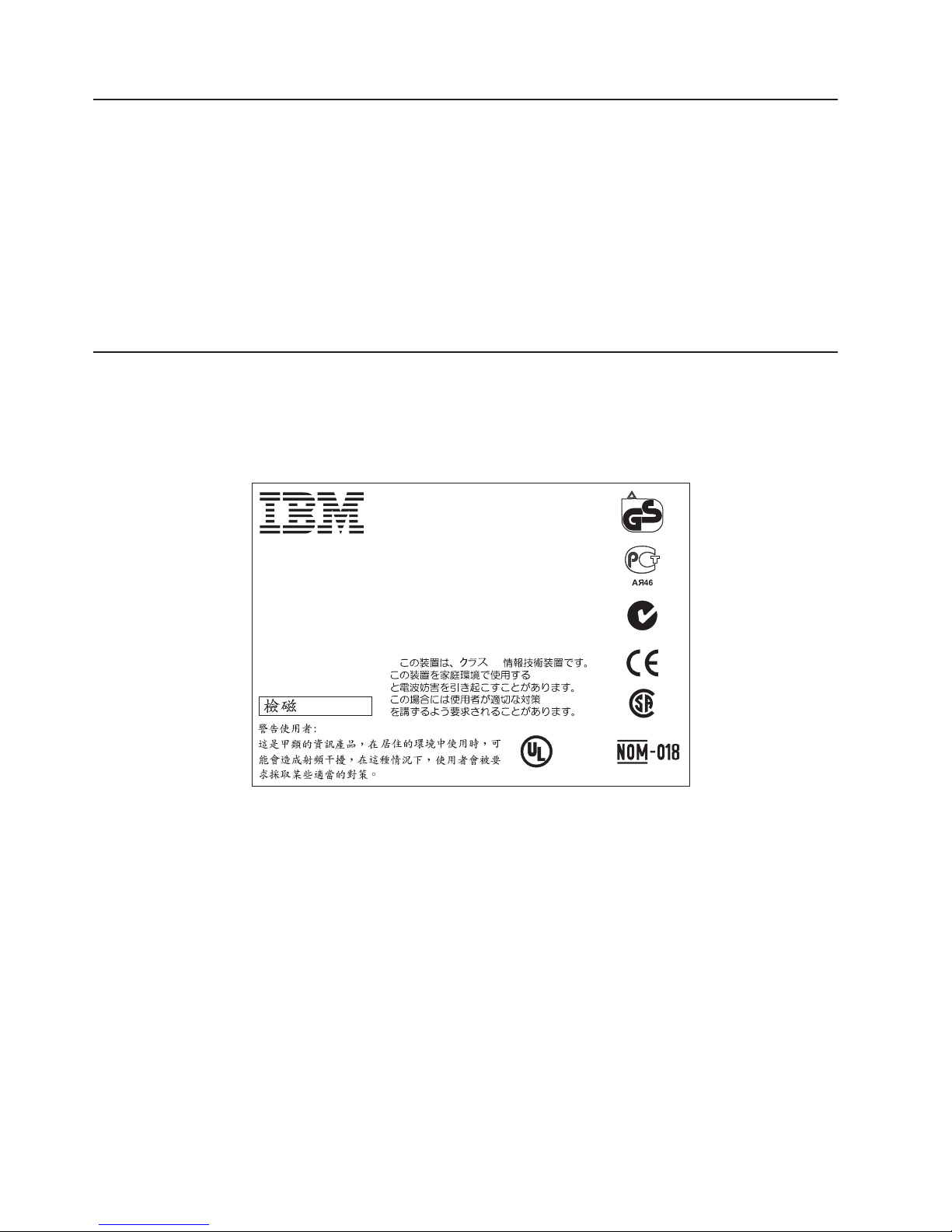
Safety label checks
Perform the following safety label checks:
1. Verify that the safety label that Figure 1 shows is installed on the 2109 Model
F16.
Marca Registrada
Type: 2109
Model: F16
V
100–240
A
2,5
kVA
0,25
Hz
47-63
Ø
1
This machine is manufactured
from new parts, or new and
used parts.
3882I054
Registered Trademark of International
®
Business Machines Corporation
IBM Canada Ltd. Registered User
®
Assembled in the US of US and Non–US Components
for International Business Machines Corporation
Armonk, NY
This device complies with part 15 of FCC rules.
Operation is subject to the following two conditions:
(1) this device may not cause harmful interference,
and (2) this device must accept any interference
received, including interference that may cause
undesired operation.
Canada ICES/NMB-003 Class/Classe A
A
VCCI-A
®
LISTED
I.T.E. 88Y4
E176896
TÜV
Rheinland
ProductSafety
geprüfte
Sicherheit
®
LR110877
P/N 18P3688
SJ000297
Figure 1. Safety label on the 2109 Model F16
2. Verify that the linecord safety label that Figure 2 on page xiii shows is installed
on the power supply of the 2109 Model F16.
CAUTION:
This unit may have two linecords. To remove all power, disconnect both
linecords. (1)
xii IBM TotalStorage SAN Switch: 2109 Model F16 User’s Guide
Page 15
PSU1 PSU2
V~
> 240
Figure 2. Linecord caution label
AC grounding
DANGER
An electrical outlet that is not correctly wired could place a hazardous
voltage on the metal parts of the system or the products that attach to the
system. It is the customer’s responsibility to ensure that the outlet is
correctly wired and grounded to prevent an electrical shock. (1)
Environmental notices and statements
This section describes the environmental notices and statements.
Laser safety
PN 18P4036
SJ000325
CAUTION:
In the United States use only GBIC units or Fibre-Optic products that
comply with FDA radiation performance standards, 21 CFR Subchapter J.
Internationally use only GBIC units or Fibre-Optic products that comply
with IEC standard 825-1. Optical products that do not comply with these
standards may produce light that is hazardous to the eyes.
This unit might contain a single-mode or a multimode transceiver Class 1 laser
product. The transceiver complies with IEC 825-1 and FDA 21 CFR 1040.10 and
1040.11. The transceiver must be operated under the recommended operating
conditions.
This equipment contains Class 1 laser products and complies with FDA radiation
Performance Standards, 21 CFR Subchapter J and the international laser safety
standard IEC 825-2.
Usage restrictions
You must terminate the optical ports of the modules with an optical connector or
with a dust plug.
Fire suppression systems
A fire suppression system is the responsibility of the customer. The customer’s own
insurance underwriter, local fire marshal, or a local building inspector, or both,
SJ000327
Safety and environmental notices xiii
Page 16

should be consulted in selecting a fire suppression system that provides the correct
level of coverage and protection. IBM designs and manufactures equipment to
internal and external standards that require certain environments for reliable
operation. Because IBM does not test any equipment for compatibility with fire
suppression systems, IBM does not make compatibility claims of any kind nor does
IBM provide recommendations on fire suppression systems.
Product recycling
This unit contains recyclable materials. You should recycle these materials where
processing sites are available and according to local regulations. In some areas,
IBM provides a product take-back program that ensures proper handling of the
product. Contact your IBM representative for more information.
xiv IBM TotalStorage SAN Switch: 2109 Model F16 User’s Guide
Page 17

About this document
This document introduces the IBM®TotalStorage™SAN Switch 2109 Model F16
(hereafter referred to as the 2109 Model F16).
Who should read this document
This document is intended for network and system administrators whose
responsibilities include administration and management of a storage area network.
Before you use this document, you should know how to service the switch
hardware, including how to analyze, isolate, report, and resolve problems. You must
also know how to safely work with electrical components. Throughout this
document, the term switch applies to the IBM 2109 Model F16 switch.
Additional information
This section contains the following information:
v A list of the documents in the 2109 Model F16 library
v A list of related documents
v A list of related Web sites
v Instructions on how to get help
v Instructions on how to get software updates
v Information about how to send your comments
2109 Model F16 library
The following documents contain information related to this product:
v IBM TotalStorage SAN Switch 2109 Model F16 Installation and Service Guide,
SY27-7623
v IBM TotalStorage SAN Switch 2109 Model F16 User’s Guide, GC26-7439 (this
document)
Related documents
You can find additional information related to the software for the 2109 Model F16
in the following documents:
v Brocade Advanced Performance Monitoring User’s Guide
v Brocade Advanced Web Tools User’s Guide
v Brocade Advanced Zoning User’s Guide
v Brocade Diagnostic and System Error Message Reference
v Brocade Distributed Fabric User’s Guide
v Brocade Fabric Manager User’s Guide
v Brocade Fabric OS Procedures Guide
v Brocade Fabric OS Reference
v Brocade Fabric Watch User’s Guide
v Brocade ISL Trunking User’s Guide
|
v Brocade Secure Fabric OS Procedures Guide
v Brocade MIB Reference
v Building and Scaling Brocade SAN Fabrics: Design and Best Practices Guide
© Copyright IBM Corp. 2001, 2003 xv
Page 18

Web sites
When you use any of the Brocade documents, you will notice that the model
numbers reflect the original Brocade switches. Table 1 provides a product matrix for
you to use to correlate the Brocade model numbers to the IBM product and model
numbers.
Table 1. Brocade and IBM product and model number matrix
Brocade model number IBM product and model number
2010 3534 Model 1RU
2400 2109 Model S08
2800 2109 Model S16
3200 3534 Model F08
3800 2109 Model F16
3900 2109 Model F32
12000 2109 Model M12
To get specific details about models and firmware that the switch supports, see the
following Web site:
www.ibm.com/storage/fcswitch/
Getting help
|
|
For detailed information about the Fibre Channel standards, see the Fibre Channel
Association Web site at:
www.fibrechannel.com/
For a directory of worldwide contact information, including technical support, see the
following Web site:
www.ibm.com/contact/
Contact your switch supplier for technical support. This includes hardware support,
all product repairs, and ordering of spare components.
Be prepared to provide the following information to the support personnel:
v The switch serial number
v The switch worldwide name
v The topology configuration
v Any output from the supportShow Telnet command
v A detailed description of the problem
v Any troubleshooting steps that have already been performed
Getting software updates
|
xvi IBM TotalStorage SAN Switch: 2109 Model F16 User’s Guide
Contact your system vendor for software updates and maintenance releases.
For utility programs to facilitate loading firmware, sample Fabric Watch
configurations, and management information base (MIB) files for switch
management by Simple Network Management Protocol (SNMP), see the following
Web site:
Page 19

www.storage.ibm.com/ibmsan/products/sanfabric.htm
How to send your comments
Your feedback is important to help us provide the highest quality of information. If
you have any comments about this document, you can submit them in one of the
following ways:
v E-mail
Submit your comments electronically to:
starpubs@us.ibm.com
Be sure to include the name and order number of the document and, if
applicable, the specific location of the text that you are commenting on, such as
a page number or table number.
v Mail or fax
Fill out the Readers’ Comments form (RCF) at the back of this document and
return it by mail or fax (1-800-426-6209) or give it to an IBM representative. If the
RCF has been removed, you can address your comments to:
International Business Machines Corporation
RCF Processing Department
Dept. M86/Bldg. 050-3
5600 Cottle Road
San Jose, CA 95193-0001
U.S.A.
About this document xvii
Page 20

xviii IBM TotalStorage SAN Switch: 2109 Model F16 User’s Guide
Page 21
Chapter 1. Introduction
This chapter describes the TotalStorage SAN Switch 2109 Model F16, hereafter
referred to as the 2109 Model F16. It provides the following information:
v “Product overview”
v “Hardware components” on page 2
v “Software components” on page 10
v “Diagnostics” on page 12
v “Managing the 2109 Model F16” on page 12
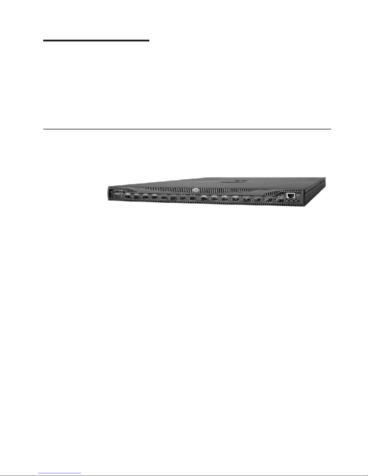
Product overview
Figure 3 shows the 2109 Model F16.
SJ000309
Figure 3. 2109 Model F16
The 2109 Model F16 is a 16-port, dual speed, auto-sensing Fibre Channel switch. It
delivers the next generation of performance and functionality for Storage Area
Networks (SANs). As the first product in the new 2109 Model F16 series, the 2109
Model F16 is functionally compatible and interoperable with the current 2109 series
of switches and the 3534 switch. The 2109 Model F16 is an enterprise class switch
that is designed to handle the large scale SAN requirements of an enterprise. You
can also use it to address the SAN requirements of a small to medium-sized
workgroup. Providing 16 ANSI Fibre Channel compliant ports (E_ports, FL_ports,
and F_ports), the 2109 Model F16 is a flexible switching platform that meets both
low-latency and high-throughput demands. Based on Application Specific Integrated
Circuit (ASIC) technology (called the Bloom), the 2109 Model F16 provides high
levels of reliability, availability, and port density. The 2109 Model F16 provides Fibre
Channel throughput at twice the previous speeds. It also has new features that
enhance the manageability and performance of the switch.
© Copyright IBM Corp. 2001, 2003 1
Page 22

The 2109 Model F16 switch provides the following features:
v 16 nonblocking ports that provide full-duplex, throughput bandwidth at either
1.0625 Gbps or 2.125 Gbps
v Fibre Channel auto-sensing ports that self-negotiate to the highest speed that is
supported by the attached devices
v Universal ports that self-configure as fabric ports (F_ports), fabric loop ports
(FL_ports), or expansion ports (E_ports)
v Trunking, which allows you to group up to four ports to create high-performance
8 Gbps inter-switch link (ISLs) between switches
v Hardware zoning that permits or denies delivery of frames to any particular
destination port address
v Frame filtering, which augments the hardware zoning capabilities of the
second-generation ASIC. The second-generation ASIC implements hardware
zoning at the port level of the switch. The expanded capabilities of the
third-generation ASICs include world wide name (WWN), device-level zoning,
protocol-level zoning, and logical unit number (LUN)-level zoning to provide the
flexibility of second generation software zoning with the enhanced security of
hardware zoning.
Note: You will need Fabric OS version 3.1 for protocol-level and LUN-level
zoning support.
v Phantom loop addressing that allows private 8-bit loop addresses to be treated
as equivalent to public loop addresses
v Support for unicast, multicast (up to 256 groups), and broadcast data traffic types
v Extensive diagnostics, system-monitoring capabilities, and dual redundant,
hot-swappable power supplies and cooling units that provide high reliability,
availability, and serviceability
v A single system board design with a 100 MHz 80960VH reduced instruction-set
computer (RISC) central processing unit (CPU) with integrated peripherals that
provide high performance
v Small form-factor pluggable (SFP) media that supports short wavelength (SWL)
optical, and long wavelength (LWL) optical
v Fabric Operating System (OS) that delivers distributed intelligence throughout the
network and enables a wide range of applications
v A flexible topology that allows the interconnection of up to 239 switches to create
a medium to large Fibre Channel fabric. The topology can change dynamically as
you add new switches or links to the fabric or as your needs change.
v Central memory architecture that maximizes switch throughput, guarantees full
transmit and receive bandwidth to all Fibre Channel ports at all times, and
enables a number of sophisticated queuing, messaging, and buffer pool
management schemes to optimize switch performance characteristics in heavily
loaded systems
v Cut-through frame routing that minimizes port-to-port latency
Hardware components
The 2109 Model F16 system board is a single-board design with a highly integrated
CPU. The Intel®80960VH CPU is a RISC core processor and is the top choice for
this platform. It provides over 70% of the functionality for the digital section of the
system board. The system uses three types of memory devices: DRAM, Flash File,
and Boot Flash. On the Fibre Channel section of the system board, the Bloom
2 IBM TotalStorage SAN Switch: 2109 Model F16 User’s Guide
Page 23

CPU subsystem
ASICs, the Serializer/Deserializer (SERDES), and the SFP media are the key
components that provide high-speed data transfer. SFP media interfaces support
SWL and LWL.
The system chassis is a 1U height enclosure with space for two power supply units
and one system board. The system board is placed in an Electromagnetic
Interference (EMI) enclosure tray as an EMI-proof system unit. Two 126-watt
removable, redundant power supplies provide hot-swappable capability. Cooling
fans are mounted in the rear to provide airflow for system cooling.
An Intel 80960VH CPU is used for switch initialization and management functions.
The CPU runs the Fabric OS and is responsible for switch initialization,
configuration, and management. IBM-designed ASICs provide the switching
functionality.
The following peripherals are also supported:
v An Ethernet port
v A serial port
v Three digital thermometers
v A real-time clock
v Two power supply controls
v General input/output (I/O)
The CPU subsystem is a mixed voltage system using 1.8 V, 2.5 V, 3.3 V, and 5 V,
depending on the device. The maximum board power consumption is 78 W.
Features
The 2109 Model F16 CPU subsystem includes the following features:
v A 80960VH-100 MHz CPU
v An SDRAM controller with parity check at 33 MHz
v A peripheral control interconnect (PCI) bus arbiter
v An on-board SDRAM with data parity to support a 16 MB configuration
v One PLCC32 Boot Flash socket to support up to 512 KB of Flash memory
v 8 MB (2 x 4 MB) Flash memory for software storage
v 10BASE-T or 100BASE-T port for management connection with RJ45 connector
v One RS232 port with DB9 connector
v 16 light emitting diodes (LEDs) to indicate the status for each port
v 16 LEDs to indicate the link speed for each port
v One LED (green) to indicate the system power-on status
v Three digital thermometers for temperature sensing
v Two analog switches to control the power supply inter-integrated circuit (I2C) bus
access
v One 3.3 V to 1.8 V dc/dc converter for Bloom ASIC core supply
v Two Bloom ASICs supporting up to 16 nonblocking ports
v 16 SERDES
v One real-time clock with a battery and 56 bytes of nonvolatile RAM (NVRAM)
Chapter 1. Introduction 3
Page 24
Electronics
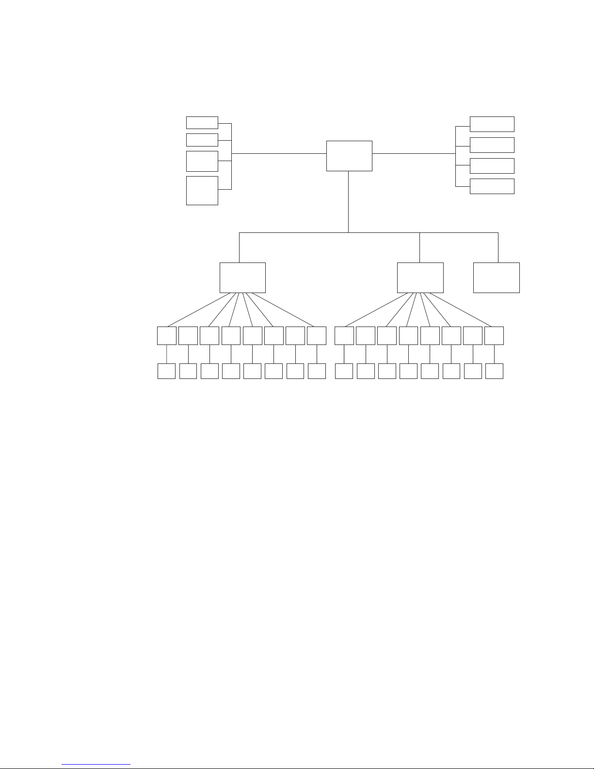
Figure 4 shows a simplified block diagram of the 2109 Model F16 CPU subsystem
electronics.
Ser/
Des
SFF
Ser/
Des
SFF
I/O Port
Clock
Temp
Sensor
Power
Supply
Control
Ser/
Des
SFF
2
I C Bus (100 KHz)
E/F/FL_Port
ASIC 0
(ports 0-7)
Ser/
Ser/
Des
Des
SFF
SFF
PCI Bus (33 MHz)
Ser/
Ser/
Des
Des
SFF
SFF
80960VH
CPU
SSLT2 Bus (106.25 MHz)
Ser/
Ser/
Ser/
Ser/
Des
Des
SFF
SFF
Ser/
Des
Des
SFF
SFF
Des
SFF
Local Bus (33 MHz)
E/F/FL_port
ASIC 1
(ports 8-15)
Ser/
Ser/
Ser/
Des
Des
SFF
SFF
Ser/
Des
Des
SFF
SFF
Ser/
Ser/
Des
Des
SFF
SFF
Ser/
Ser/
Des
Des
SFF
SFF
RS232 Port
User Flash
Boot Flash
SDRAM
Ethernet
MAC/PHY
Ser/
Ser/
Des
Des
SFF
SFF
Ser/
Ser/
Des
Des
SFF
SFF
SJ000310
Figure 4. Simplified 2109 Model F16 CPU subsystem block diagram
Embedded processor
The embedded processor is an Intel 80960VH processor with a clock speed of 100
MHz. It contains the following features:
v A high-performance RISC processor core (compatible with the 2109 series of
switches and the 3534 switch)
v An integrated EDO memory controller (for DRAM, SRAM, ROM, and Flash
memory)
v A PCI bus interface
v A complex programmable logic device (CPLD) for SDRAM control
v Two direct memory access (DMA) channels
v An I2C interface
v General purpose I/O
You access system memory through the local bus. The external CPLD SDRAM
device provides SDRAM controller functionality at 33 MHz. It supports parity
checking to enhance the data integrity of the system. The CPU communicates with
the ASIC and the 10BASE-T or 100BASE-T Ethernet media access controller
(MAC) through the PCI interface. An external PCI bus arbiter enables the Ethernet
device to be a bus master.
You can also access the RS232 Universal Asynchronous Receiver Transmitter
(UART) serial port through the local bus. Other I/O peripherals, such as the
real-time clock, the two power supply controls, the LEDs, the three digital
4 IBM TotalStorage SAN Switch: 2109 Model F16 User’s Guide
Page 25

thermometers, and miscellaneous I/O are handled by the I2C bus of the CPU. The
CPU is the only I2C bus master in the system. The RS232 port and drivers,
Ethernet MAC/PHY, and LEDs are external components to the CPU. An RJ45
connector provides Ethernet connection to external systems. The DB9 RS232 is a
ribbon-cable connection through the on-board 10-pin header.
Bus operations
The interface between the embedded processor, the ASICs, and the 10BASE-T or
100BASE-T Ethernet MAC is implemented by using a PCI bus. All PCI devices on
the bus are PCI Revision 2.2 compliant. The PCI bus interface operates at 32-bit,
up to 33 MHz and has a worldwide even parity bit. A slave-only PCI interface is
provided by each ASIC to allow the processor to program various registers, routing
tables, and so on within the chip. An external PCI bus arbiter enables the Ethernet
device to be a bus master.
The local bus, a 32-bit multiplexed burst bus, provides the interface between the
system memory and the I/O. Because the integrated EDO memory controller on the
CPU allows only direct control for DRAM, SRAM, ROM, and Flash memory, the
external CPLD controller is included to provide SDRAM controller functionality.
The I2C bus provides peripheral I/O control for the LEDs, the thermometers, and
general I/O functions. The 80960VH CPU serves as the master on the I2C bus.
Each Bloom ASIC is an eight-port Fibre Channel switch controller. There are two
Bloom ASICs to support up to 16 ports. The communication between ASICs is over
a proprietary 10-bit wide SSTL2 bus running at 106.25 MHz. An SSTL2 bus is also
used between the Bloom ASICs and the SERDES.
Memory
The system design uses three types of memory devices:
v DRAM
v Flash File
v Boot Flash
Two on-board SDRAM chips provide up to 16 MB for system memory. Two
additional SDRAM chips provide data parity. The printed circuit board (PCB)
SDRAM footprint is designed to be compatible with 64 MB, 128 MB, and 256 MB
devices. An external CPLD device added to the local bus provides control functions
for the 80960VH processor.
The system provides 4 MB of on-board redundant Flash File memory for software
and data storage. The Boot Flash is an 8-bit Flash device socket that is used only
for system start. The Boot Flash device contains a block area for startup code
protection. The PLCC32 socket supports 3.3 V Boot Flash memory up to 512 KB.
Central memory: As with the 2019 series of switches and the 3534 switch, the
2109 Model F16 is based on a central memory architecture. In this architecture, a
set of buffers in the central memory is assigned to each port to be used for receipt
of frames. As an ASIC port receives and validates a frame, it stores the frame in
one of its receive buffers in the central memory and forwards a routing request (a
Put message) to the appropriate destination ports. When a destination port is
capable of transmitting the frame, it reads the frame contents from central memory
and forwards the frame to its transmit interface. It does not wait for the frame to be
written in memory, unless the port is busy. After it removes an entry for a frame
from its internal transmit queue in preparation for transmitting a frame, the
Chapter 1. Introduction 5
Page 26

destination port sends a transmission complete message (a Finish message) to the
port that received the frame. This method allows the receiving port to reuse the
buffer for subsequent frames received.
The central memory is also incorporated into the ASICs. Frames received on the
ports in an ASIC are written into the portion of central memory in the receiving chip.
Received frames cannot be written into the sections of central memory located in
other ASICs. All transmitters in a 2109 Model F16 switch can read from the
memories in any of the ASICs, through inter-chip connections clocked at 106.25
MHz.
Each ASIC contains RAM devices plus data path crossbar logic that is used to
implement the central memory. Memory blocks are accessed in a time-sliced
fashion. The buffer pool can be split into 2112-byte buffers or into 312-byte
mini-buffers. If frames that need to be buffered are smaller than the maximum 2112
bytes, using mini-buffers effectively expands the buffer pool and increases the
efficiency of memory usage by providing more (but smaller) receive buffers.
Additionally, the Bloom ASIC provides a special memory interface (SMI). The SMI
provides the firmware with a mechanism to read and write frame contents to and
from the ASIC. It also supports higher throughput transfers. The SMI includes a set
of two buffers that are large enough for an entire maximum-sized frame to be
transferred in a single operation. Additionally, because two buffers are available, the
firmware can perform a read or write on a frame in one of the buffers while the
ASIC streams another frame into the other buffer.
ASICs
Two ASICs within the system provide the switching functionality. Each ASIC
provides eight Fibre Channel ports that you can use to connect to external node
ports (N_ports) (as an F_port), external loop devices (as an FL_port), or to other
3534 or 2109 series boxes (as an E_port).
Each port can operate at either 1.0625 Gbps or 2.125 Gbps link speeds. The ASIC
contains the Fibre Channel interface logic, message and buffer queuing logic,
receive buffer memory for the eight on-chip ports, and other support logic.
The Bloom ASICs are PCI slaves to the CPU. The two ASICs interface through an
inter-chip 10-bit SSLT2 bus connection clocked at 106.25 MHz. A 16-channel
SERDES is used to support 16 ports. The interface between ASIC and SERDES is
also a 10-bit SSTL2 bus running at 106.25 MHz. The SERDES converts the 10-bit
wide parallel data from the SSTL2 bus into high-speed serial data for the SFP
media and vice versa. The SERDES supports single data rate (SDR) or double data
rate (DDR) transfer between the SERDES and the SFP media. The DDR operation
supports 2.125 Gbps data transfer rate between ASICs. Implementing the SERDES
external to the ASIC reduces the risk of silicon packaging as well as the risk of
running 2.125 Gbps signals on a board with a long trace length.
The SFP media interfaces to external devices and enables support for shortwave
laser and longwave laser. Two LEDs for each port provide port status and link
speed information.
Control Message Interface: The 2109 Model F16 Control Message Interface
(CMI) consists of a set of control signals that are used to pass hardware-level
messages between ports. Recipient ports use these control signals to inform
transmitting ports when a new frame needs to be added to the output queue of the
transmitter. Transmitting ports also use the CMI to inform recipient ports that a
6 IBM TotalStorage SAN Switch: 2109 Model F16 User’s Guide
Page 27

Ports
frame transmission has completed. A recipient port is free to reuse a receive buffer
when it receives notification that the frame was transmitted. In the case of multicast,
multiple notifications are required to determine when a receive buffer is freed.
The CMI interfaces for the ASICs are connected inside each ASIC through a
message crossbar, implementing a barrel shift message scheme. Each chip time
slices its output port to each possible destination chip in the switch. If it has a
message to send to a particular destination during the corresponding time slot, the
chip uses the time slot to send the message. Otherwise, the output port lines are
driven to indicate that no message is present.
The time slicing of the output CMI control signals of the ASICs are arranged out of
phase from each other so that each chip’s output port is time sliced to a different
destination chip in any given clock cycle. Messages that display at the input control
signal interface of a given ASIC are also time sliced through each possible source
chip in the switch.
The 2109 Model F16 supports the following port types:
v Optical ports
v Ethernet port
v Serial port
Each ASIC in the 2109 Model F16 switch connects up to eight SFP media. SFP
devices are encased in metal to ensure low emissions and high thermal
management. They are hot-swappable and use industry-standard local channel
connectors. Each port provides ISL, loop, and fabric (E, F, and FL respectively) type
connectivity that the 2109 Model F16 senses automatically. It requires no
administration to identify the port type.
Optical ports
For optical ports, the 2109 Model F16 uses SFP fiber-optic transceivers that convert
electrical signals to optical signals (and optical signals to electrical signals).
Each SFP fiber-optic transceiver is capable of transmitting at both 1 and 2 Gbps
speeds and supports:
v 850 nm SWL on multimode fiber-optic cable
v 1310 nm LWL on single-mode fiber-optic cable
v 1550 nm ELWL 5 on single-mode fiber-optic cable
These miniature optical transceivers provide high port density and deliver twice the
port density of standard removable GBIC transceivers.
Ethernet port
The 2109 Model F16 provides a fully IEEE-compliant 10BASE-T or 100BASE-T
Ethernet port for switch management console interface. When a device is
connected to the port, both ends negotiate to determine the optimal speed. The
Ethernet port uses an RJ45 connector. Two LEDs are for the port. One LED
indicates transmit and receive activity and the other LED indicates speed (10 Mbps
or 100 Mbps). You can configure the TCP/IP address for the port from the serial
port.
Serial port
The 2109 Model F16 provides an RS232 serial port. The serial port uses a DB9
connector. The connector is a header pin block on the system board. The
Chapter 1. Introduction 7
Page 28

Enclosure
parameters of the serial port are fixed at 9600 baud, 8 data bits, no parity, no
hardware flow control, 1 start and 1 stop bit.
Use this connector to configure the Internet protocol (IP) address and to recover the
factory default settings of the switch should Flash memory contents be lost. You
should not use the serial port connection to perform normal administration or
maintenance functions. Accessible functions are limited to connecting a terminal to
the port to reinitialize the switch defaults, which restores the switch to its factory
configuration. This is required to restore the switch passwords to a known state and
to allow customers to set a specific switch IP address.
The 2109 Model F16 enclosure is designed so that you can mount it in a 19-inch
rack, with a height of 1 RETMA unit (1µ). But you can also use it in a tabletop
configuration. The enclosure houses dual-redundant power supplies, dual-redundant
fan assemblies, and a system board that supports the two ASICs and the CPU.
The 2109 Model F16 enclosure has forced-air cooling. The fans push the air from
the rear chassis intake through the enclosure and exhaust the air through venting
holes in the front panel. The SFP media, the cooling fan, and the power supplies
are hot-swappable so that they can be removed and replaced without interrupting
the system power.
The top panel of the 2109 Model F16 enclosure can be removed without tools,
allowing access to the system board. The enclosure design provides for simple
assembly of the system board into the enclosure, allowing for ease of manufacture
and maintenance. All pieces of the product are modular. You can perform all
maintenance without special tools.
Power supply
On the front of the unit, there are two port connections (an RS232 connection and
an RJ45 connection). The RJ45 connection provides a 10BASE-T or 100BASE-T
Ethernet port for a full system management console interface. The RS232
connection provides a serial port interface for setting the IP address of the switch
and for resetting the switch to factory defaults.
The fibre-optic cables, Ethernet cables, and serial port cables are located on the
front of the switch. AC power input cables, power supplies, and cooling modules are
inserted and removed from the rear of the switch.
The 2109 Model F16 power supply is a hot-swappable switching unit, allowing 1+1
redundant configurations. The unit is a universal power supply capable of
functioning worldwide without voltage jumpers or switches. The fully enclosed,
self-contained unit has its own internal fans to provide cooling. It is auto-ranging in
terms of accommodating input voltages. The power supply has three dc outputs
(3.3 V, 5 V, and 12 V) that provide a total output power of 126 maximum usable
watts. The power supplies plug directly into the enclosure from the rear of the unit,
mating to internal blind connectors that connect both the dc outputs and the
interface signals to the system backplane. The power supply provides an integral
on/off switch, input filter, and power indicator.
8 IBM TotalStorage SAN Switch: 2109 Model F16 User’s Guide
Page 29
LEDs
|
|
Table 2 lists the power supply requirements.
Table 2. Power supply requirements
Specification Value
Total power 126 watts delivered over temperature range
Input voltage 100 - 240 V ac, auto range
Input line frequency 47 - 63 Hz
Inrush current 10 Amps peak > 300 microseconds (hot or
cold start)
Harmonic distortion Active power factor correction per
IEC1000-3-2
Input line protection Fused in both hot and neutral lines
Maximum dimensions 8.255 cm (3.25 in.) wide, 3.81 cm (1.5 in.)
high, and 36.83 cm (14.5 in.) deep
Redundancy Dual supplies 1+1 redundant-hot-pluggable,
active current share
This section describes the LEDs located on front and back panels of the 2109
Model F16.
|
|
|
|
Front panel
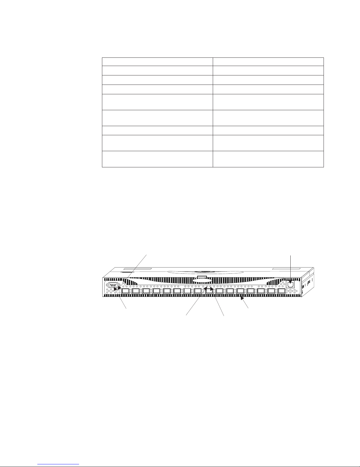
Figure 5 shows the front panel of the 2109 Model F16 switch. The front panel
provides access to the serial port, Ethernet port, and the fiber optic ports, and
shows the corresponding port LED and the power LED.
|
Switch Status LED
Serial Port
Port Status LED (16X)
Figure 5. Front panel of the 2109 Model F16
|
|
|
|
|
|
|
The ports on the front panel are color-coded in groups (four blue ports alternate
with four blue outlined ports) to indicate which ports you can use in the same ISL
Trunking group.
Note: ISL Trunking is a feature that enables traffic to be evenly distributed across
the links between two adjacent switches while preserving in-order delivery. It
is managed through the software. For more information, see the Brocade ISL
Trunking User’s Guide.
Port Speed LED (16X)
Optical Port (16X)
Ethernet Port
SJ000151
|
|
|
Back panel
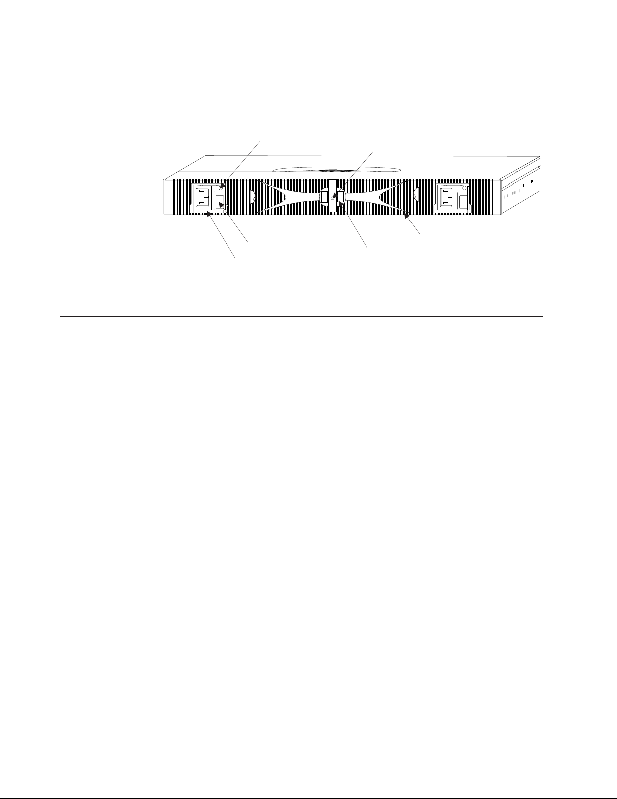
Figure 6 on page 10 shows the back panel of the 2109 Model F16 switch. The back
panel provides access to the fan trays and the power supplies, and shows the
Chapter 1. Introduction 9
Page 30
|
|
|
status LED. Each power supply also has an LED that indicates the status of that
power supply. The power supplies, fan trays, chassis, and system board are all field
replaceable units (FRUs).
|
|
|
|
Figure 6. Back panel of the 2109 Model F16
|
Software components
This section briefly describes the software components of the 2109 Model F16.
Power Supply LED (2X)
A/C Power Switch (2X)
Power Supply (2X)
System Board LED
Fan Tray Assembly (2X)
Spring Latch (2X)
SJ000152
Firmware
|
|
|
|
|
|
|
Features and functions
|
|
|
|
|
|
|
The 2109 Model F16 switch is supported by Fabric OS version 3.0 or later.
The Fabric OS is implemented in firmware and manages the operation of the 2109
Model F16 switch. The firmware is designed to make a switch easy to install, to
use, and to manage. You can view the firmware as a set of applications that run on
top of a proprietary real-time operating system. The Fabric OS is made up of the
following two major software components:
v Firmware that initializes and manages the switch hardware
v Diagnostics that perform component self-testing algorithms for fault isolation
during the manufacturing process and in customer installations
For information about Fabric OS, see Brocade Fabric OS Procedures Guide, and
Brocade Fabric OS Reference.
The software that supports the 2109 F16 includes these features and functions.
Secure Fabric OS
The Fabric OS supports the Secure Fabric OS, which includes security features that
you can use with other security tools (Advanced Security feature) to implement
increased security in your SAN. For more information, see the Brocade Secure
Fabric OS User’s Guide
|
|
|
|
|
Web Tools
Web Tools provides a graphical user interface (GUI) that enables you to monitor
and manage entire fabrics and individual switches and ports from a standard
workstation. For more information, see the Brocade Advanced Web Tools User’s
Guide.
10 IBM TotalStorage SAN Switch: 2109 Model F16 User’s Guide
Page 31

|
|
|
|
|
|
|
|
|
|
|
Full fabric switch upgrade
The full fabric switch upgrade feature provides connectivity of up to 16 other
switches, Advanced Zoning, and Fabric Watch. Activation keys enable all 16 ports
as universal (F_port, FL_port, or E_port) ports, and enable Advanced Zoning and
Fabric Watch.
v Advanced Zoning logically groups a SAN fabric into an unlimited number of
secure, private zones. For more information, see the Brocade Advanced Zoning
User’s Guide.
v Fabric Watch is an intelligent fabric monitor, giving each switch the capability to
identify and isolate potential faults, as well as to optimize fabric-wide
performance. For more information, see the Brocade Fabric Watch User’s Guide.
|
|
|
Optional licensed features
|
|
|
|
|
|
|
|
|
|
|
|
|
|
|
|
|
Auto-sensing speed negotiation
The 21089 F16 ASIC supports link operation at either 2 Gbps or 1 Gbps.
Auto-sensing negotiation allows easy configuration.
For Fabric OS version 3.0.2 or later, there are several optional licensed features to
enhance the Fibre Channel switch.
Performance Bundle
Performance Monitoring
Advanced Performance Monitoring is a comprehensive tool for monitoring
the performance of networked storage resources. This tool helps reduce the
total cost of ownership and over-provisioning while enabling SAN
performance tuning, reporting of service level agreements, and greater
administrator productivity. Advanced Performance Monitoring provides SAN
performance management through an end-to-end monitoring system.
For more information, see the Brocade Advanced Performance Monitoring
User’s Guide.
ISL Trunking
Trunking enables traffic to be distributed across available ISLs while still
preserving in-order delivery.
For more information, see the Brocade ISL Trunking User’s Guide.
|
|
|
|
|
|
|
|
|
|
|
|
|
|
Extended Fabrics
The Extended Fabrics feature extends SAN fabrics beyond the Fibre Channel
standard 10 km. It enables high performance applications over extended distances
for storage consolidation, data protection, disaster tolerance, and data sharing.
Fabric Manager
Fabric Manager provides a GUI that allows you to monitor and manage a fabric
from a standard workstation. Fabric Manager provides high-level information about
all switches in the fabric, launching the Web Tools application when more detailed
information is required. Fabric Manager provides improved performance over Web
Tools alone.
For more information, see the Brocade Fabric Manager User’s Guide.
Remote Switch
The Remote Switch feature extends the distance of SAN fabrics by enabling two
Fibre Channel switches to interconnect over an asynchronous transfer mode (ATM)
Chapter 1. Introduction 11
Page 32

|
|
|
wide area network (WAN). With this feature, you can stage and manage data
transfers across a pair of Fibre Channel switches that are connected to a pair of
CNT open system gateways.
|
|
|
|
|
|
|
|
|
|
|
|
|
|
|
|
QuickLoop (request price quote)
QuickLoop enables servers with Fibre Channel Arbitrated Loop private loop host
bus adapters to communicate with Fibre Channel storage devices through IBM
TotalStorage SAN Switches.
For more information, see the Brocade QuickLoop User’s Guide.
Advanced Security feature
The Advanced Security Feature provides customizable security restrictions through
local and remote management channels on a switch fabric. The feature allows you
to create policies to customize fabric management access and to specify which
switches and devices can join the fabric, view statistics related to attempted policy
violations, manage the fabric-wide Secure Fabric OS parameters through a single
switch, create temporary passwords specific to a login account and switch, and
enable and disable Secure Fabric OS as desired.
Note: To activate these features, go to the following Web site:
www.ibm.com/storage/key/
For more information, see the Brocade Secure Fabric OS User’s Guide.
Managing the 2109 Model F16
The following management interfaces allow you to monitor fabric topology, port
status, physical status, and other information to aid in system debugging and
performance analysis:
v Command-line interface (CLI) through a Telnet connection
v Advanced Web Tools
v SCSI Enclosure Services (SES)
v SNMP applications
You can use all these management methods either in-band (Fibre Channel) or
out-of-band (Ethernet), except for SES, which can be used for in-band only.
For more information about these management interfaces, see the Brocade Fabric
OS Procedures Guide.
Diagnostics
The 2109 Model F16 switch supports a set of power-on self tests (POSTs), as well
as tests that you can invoke by using Telnet commands. These diagnostics are
used during the manufacturing process as well as for fault isolation of the product in
your installation.
Diagnostic environment
Most diagnostics are written to run in the VxWorks environment. However, as
VxWorks does not run without a working SDRAM, a SDRAM/boot EEPROM test is
run as part of the pre-VxWorks startup code to verify that the basic
processor-connected memories are functioning properly.
12 IBM TotalStorage SAN Switch: 2109 Model F16 User’s Guide
Page 33

Hardware support
Loop-back paths for frame traffic are provided in the hardware for diagnostic
purposes. You can use a loop-back path within the ASIC, at the final stages of the
Fibre Channel interface, to verify that the internal Fibre Channel port logic is
functioning properly, as well as paths between the interface and the central memory.
Additionally, the SerialLink macro within the ASIC includes a serial data loop-back
function that can be enabled through a register in the corresponding ASIC.
Diagnostics are provided to allow traffic to be circulated between two switch ports
that are connected with an external cable. This allows the diagnostics to verify the
integrity of the final stage of the SERDES interface, as well as the media interface
module.
Diagnostic coverage
The POST and diagnostic commands concentrate on the Fibre Channel ports and
verify switch functionality of the 2109 Model F16 switch. For more information, see
the Brocade Diagnostic and System Error Message Reference.
Chapter 1. Introduction 13
Page 34

14 IBM TotalStorage SAN Switch: 2109 Model F16 User’s Guide
Page 35

|
Chapter 2. Operating the 2109 Model F16
|
|
|
|
|
|
|
|
Turning on and off the 2109 Model F16
|
|
|
|
|
|
|
|
Interpreting LED activity
|
|
|
|
|
|
This chapter describes how to operate the 2109 Model F16 and includes the
following information:
v “Turning on and off the 2109 Model F16”
v “Interpreting LED activity”
v “Interpreting POST” on page 19
v “Maintaining the switch” on page 20
To turn on the 2109 Model F16, connect one or both of the power supplies to a
power source, then flip the ac power switch to “I”.
To turn off the switch, flip the ac switch for both power supplies to “O”.
Note: When you remove all power from the switch, a system reset is triggered.
When you restore the power, all devices are returned to the initial state, and
the switch runs a POST, a one-minute system check.
You can determine system activity and status by monitoring the activity of the LEDs
on the switch.
Note: The LEDs might flash green, orange, or yellow during a POST. This is
normal and does not indicate a problem unless the LEDs do not return to a
normal pattern after a POST completes.
|
|
|
|
|
|
|
|
|
|
|
|
|
|
|
|
|
|
The 2109 Model F16 has the following LEDs:
Port Status LED
This front panel LED indicates the status of each port. There are 16 port
status LEDs, located above and to the left of each port.
Port Speed LED
This front panel LED indicates the speed of each port. There are 16 port
speed LEDs, located above and to the right of each port.
Switch Status LED
This front panel LED indicates whether the switch is on and has
successfully started. There is one switch status LED, located below the
serial port.
Power Supply LED
This back panel LED indicates the status of each power supply. There are
two power supply LEDs, one on each power supply.
Switch Status LED
This back panel LED indicates whether the switch is on and has
successfully started, or is running diagnostics. There is one switch status
LED, located in the center of the back panel.
© Copyright IBM Corp. 2001, 2003 15
Page 36
|
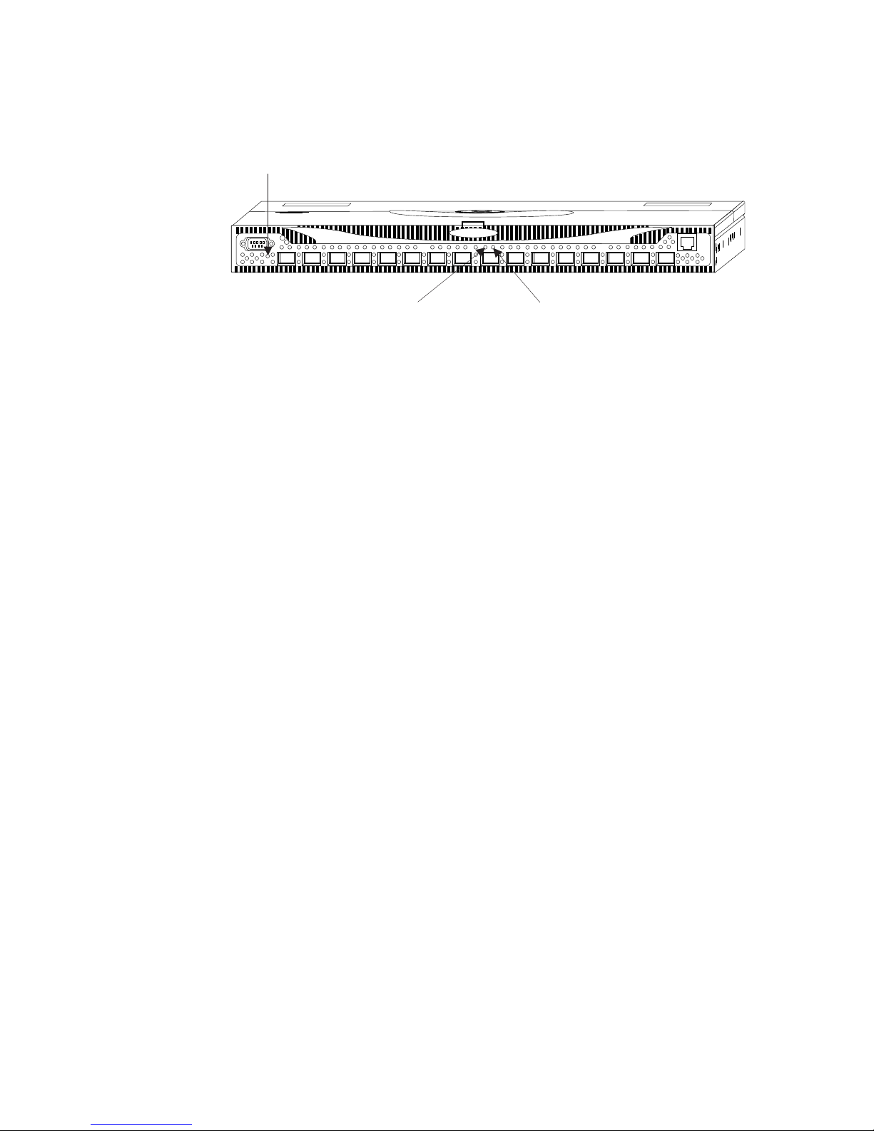
LEDs on the front panel
|
Figure 7 shows the front panel with the different LEDs identified.
|
|
Switch Status LED
Port Status LED (16X)
|
|
Figure 7. Front panel LEDs
Port Speed LED (16X)
SJ000154
|
|
|
|
Table 3 on page 17 describes the front panel LEDs. It shows the LED names,
purposes, locations, colors, and status. It also lists the actions that you should take
while you monitor LED activity.
16 IBM TotalStorage SAN Switch: 2109 Model F16 User’s Guide
Page 37

|
|
Table 3. Front panel LED patterns during normal (non-POST) operation
||||||
LED name and
purpose
||||||
|
Port Status LED;
|
|
indicates port status
LED location LED color Status Recommended action
Above and to the
left of each port
No light No light or signal carrier
|
||
|
Steady green The port is online (that
|
|
|
|
|
|
|
|
|
|
|
|
Slow-flashing green
(on 1 second; off 1
second)
|
|
|||
|
|
||
|
Fast-flashing green
(on 1/4 second; off
1/4 second)
Flickering green The port is online, with
|
|
||||
|
||
Flashing or steady
yellow
Steady orange The port is receiving
|
|
|
|
|
|
|
|
|
|
|
Slow-flashing orange
(on 1 second; off 1
second)
|
|
||
|
|
|
||||
|
||||||||
Port Speed LED;
indicates port speed
||||
Above and to the
right of each port
Fast-flashing orange
(on 1/4 second; off
1/4 second)
Alternating green and
yellow
No light The port is transmitting
Steady green The port is transmitting
Check the media and the
(media or cable) is
detected.
is, connected to an
external device) but has
no traffic.
The port is online but is
segmented, indicating a
loopback cable or
incompatible switch.
The port is internal
loopback (diagnostic).
traffic flowing through
the port.
POST is running. No action is required.
light or a signal carrier
is detected, but is not
yet online.
The port is disabled as
a result of diagnostics
or the portDisable
command.
The port is faulty. Reset the switch from a
The port is bypassed. Reset the port from a
or receiving at 1 Gbps.
or receiving at 2 Gbps.
cable.
No action is required.
Verify that the correct
device is connected to
the port.
No action is required.
No action is required.
No action is required.
Reset the port from a
management station.
management station.
management station.
No action is required.
No action is required.
Chapter 2. Operating the 2109 Model F16 17
Page 38

|
Table 3. Front panel LED patterns during normal (non-POST) operation (continued)
||||||
LED name and
purpose
||||
|
|
Switch Status LED;
|
|
|
indicates whether
|
|
|
the switch is on and
|
|
|
has successfully
|
|
started
LED location LED color Status Recommended action
Below the serial
port
No light Either the switch is off,
the startup process is
not complete, or the
startup has failed.
|
||
|
|
|
||
|
|
|
|
|
Steady green The switch is on and
startup has successfully
completed.
Flashing green A diagnostic failure has
occurred on one or
more ports.
|
|
|
|
|
LEDs on the back panel
|
Figure 8 shows the back panel of the switch with the different LEDs identified.
|
|
Power Supply LED (2X)
Switch Status LED
Verify that the switch is
on and that the startup
process has had time to
complete. If there is still
no light, contact your
switch supplier.
No action is required.
Errors might be listed in
the error log. See the
Brocade Diagnostic and
System Error Message
Reference for more
information.
|
|
Figure 8. Back panel LEDs
|
|
|
|
|
|
Table 4. Back panel LED patterns during normal (non-POST) operation
||||||
LED name and
purpose
|
||||||
Power Supply LED;
|
|
indicates the status
|
|
of the related power
|
|
supply
||||
Table 4 describes the back panel LEDs. It shows the LED names, purposes,
locations, colors, and status. It also lists the actions that you should take while you
monitor LED activity.
LED location LED color Status Recommended Action
On each power
supply
No light The power supply is not
Steady green The power supply is
18 IBM TotalStorage SAN Switch: 2109 Model F16 User’s Guide
providing power.
providing power.
SJ00155
Verify that the power
supply is on and that the
power cable is connected
to a valid power source.
No action is required.
Page 39

Table 4. Back panel LED patterns during normal (non-POST) operation (continued)
|
||||||
LED name and
purpose
||||
|
|
Switch Status LED;
|
|
|
indicates whether
|
|
|
the switch is on and
|
|
|
has successfully
|
|
started
LED location LED color Status Recommended Action
Center of back
panel
No light Either the switch is off,
the startup process is
not complete, or the
startup has failed.
|
||
|
|
|
||||
||
|
|
|
|
|
Steady green The switch is on and
startup has successfully
completed.
Steady yellow A diagnostic command
is in progress.
Slow-flashing yellow A diagnostic failure has
occurred on one or
more ports.
|
|
|
|
|
|
Interpreting POST
Verify that the switch is
on and that the startup
process has had time to
complete. If there is still
no light, contact your
switch supplier.
No action is required.
No action is required.
Errors might be listed in
the error log. See the
Brocade Diagnostic and
System Error Message
Reference for more
information.
|
|
|
|
|
|
|
|
|
|
|
|
|
|
|
|
|
|
|
|
Each time you power on or reset the switch, the switch automatically performs a
POST, a one-minute system check. The LEDs flash during a POST, but all LEDs
should return to a normal state when the POST is complete.
To determine whether a POST completed without errors, verify that all LEDs return
to a normal state after the POST is complete. If one or more LEDs continue to
flash, see “Interpreting LED activity” on page 15. Verify that the flashing is not due
to the switch being configured to beacon.
Note: The switchBeacon command sets the switch beaconing mode on or off if
the operand is 1 or 0 respectively. When you turn on beaconing mode, the
port LEDs flash orange in a running pattern from port 0 - port 15, port 15 port 0, and then back to port 15 again.
For more information about the switchBeacon command, see the Brocade Fabric
OS Reference.
Note: If the switch prompt does not display, or if the Power Supply LED or the
Switch Status LED flashes, the POST did not successfully complete. You
should then return the switch for repairs.
If errors are detected during a POST, error messages are written to the system
error log. You can view this error log by using the errShow command. For
information about error messages, see the Brocade Diagnostic and System Error
Message Reference.
Chapter 2. Operating the 2109 Model F16 19
Page 40

|
Maintaining the switch
|
|
|
|
|
|
|
|
|
|
|
|
|
|
|
|
|
The 2109 Model F16 does not require any physical maintenance and is designed to
minimize the chance of failure. However, if a failure occurs, the you can replace
some of the switch components. For more information, see IBM TotalStorage SAN
Switch 2109 Model F16 Installation and Service Guide. Diagnostic tests are
provided to help troubleshoot the hardware and the firmware.
The diagnostic tests include tests of internal connections and circuitry, fixed media,
and any SFP modules and fiber optic cables that are in use. The tests are
implemented by commands, either through a Telnet session or through a terminal
that is set up for a serial connection to the switch. Some tests require that the ports
be connected by external cables, allowing the diagnostics to verify the serializer or
deserializer interface, as well as the attached SFP and cable.
All diagnostic tests are run at link speeds of 1 Gbps and 2 Gbps. As a result, the
transmit and receive speed of the links can be temporarily locked at one speed or
the other while the diagnostic tests are running. For information about the specific
diagnostic tests and how to run them, see the Brocade Diagnostic and System
Error Message Reference.
20 IBM TotalStorage SAN Switch: 2109 Model F16 User’s Guide
Page 41

Appendix A. Standards and protocol compliance
IBM is committed to providing products that comply with industry standards and
protocols.
Standards
The IBM 2109 Model F16 switch is compliant with the following standards:
v Fibre Channel ANSI Specifications
– FC-PH, version 4.3 (Fibre Channel Physical)
– FC-PH-2, version 7.4 (Fibre Channel Physical, Enhanced) for Multicast and
Broadcast functions
– FC-PH-3, version 9.4
– FC-SW-2, version 4.4 (Fibre Channel Switched Fabric)
– FC-FG Revision 3.5 (Fabric Generic Requirements)
– FC-AL, version 4.5 (Arbitrated Loop)
– FC-AL-2, version 5.7 (Arbitrated Loop Extensions)
– FC-FLA, version 2.7 (Fabric Loop Attach)
– FC-GS-2, version 5.3 (Generic Services)
– FC-GS-3, version 6.42 or later (Generic Services)
– FC-PLDA, version 2.1 (Private Loop Direct Attach)
– FC-Tape Fibre Channel Tape (FC-Tape)
– FCP-2Rev4 (Fibre Channel Protocol)
– FC-FS Revision 0.2 or later
– FC-IP
v SCSI Enclosure Services, Rev 8a
v EA/TIA RS-232 Serial Port specification
v Gigabit Interface Converter Definition Document, Sun, and so on
v IEEE 802.3 for Ethernet
Protocol compliance
The 2109 Model F16 complies with the following standards and protocols.
Support for Fibre Channel ports
All ports on the 2109 Model F16 are universal ports and support F_port
(point-to-point), FL_port (loop), and E_port (switch-to-switch) port connections.
Fibre Channel class operation
The 2109 Model F16 supports Fibre Channel Classes 2, 3, and F operations on all
ports.
Auto-configuration
All ports support E_ports to allow for cascading switches to form larger fabrics.
E_ports are auto-configuring. Linking ports from any two switches automatically
configure an E_port connection to form the fabric. The 2109 Model F16 supports a
trunking option that binds up to four ports together as a high-performance trunk
group. In this trunking configuration, inter-switch data transfers can occur at an
© Copyright IBM Corp. 2001, 2003 21
Page 42

aggregate rate of 800 MBps in both directions. The trunk group is automatically
configured on the ports of the switch as the links between the switches are
connected.
In-order delivery
The 2109 Model F16 guarantees in-order delivery of frames between source F/FL
and destination F/FL ports. In-order delivery is supported across any arbitrary switch
configurations or fabric topologies.
Flexibility of fabric topology and operation
The 2109 Model F16 implements the Fabric Shortest Path First (FSPF) routing
protocol as specified in the T11 FC-SW-2 standard. Fabric topology and operation
are automatically adjusted and dynamically distributed to the fabric as new switches
and links are added to the fabric. This is completed with no operator intervention.
When a link is added or removed, the routes are recalculated. The switch adopts a
minimal disruption algorithm to minimize the impact of the route recalculation. To
minimize disruption, the switch only reroutes traffic due to a new shortest path (if
one has been established) or if new load sharing is required.
22 IBM TotalStorage SAN Switch: 2109 Model F16 User’s Guide
Page 43

Appendix B. Interoperability, reliability, serviceability, and
specifications
This appendix provides the following information:
v “Interoperability”
v “Reliability and serviceability”
v “Specifications” on page 24
Interoperability
This section includes information about interoperability.
Switch interoperability
The 2109 Model F16 switch supports both 1 Gbps and 2 Gbps transmit and receive
rates with auto-negotiation. The actual data signaling rate that is used on a port is
automatically sensed and is set to the rate that is supported by a device or devices
that are attached to the port. The 2109 Model F16 has been tested and is compliant
with the current Fibre Channel standards. The 2109 Model F16 is compatible with
most current-generation switches N_ports, NL_ports, and E_ports, as well as host
adapters, Redundant Array of Independent Disks (RAID) storage devices, hubs, and
Fibre-SCSI bridge devices, including the 3534 and 2109 series of switches.
Implementation in existing environments
Because the 2109 Model F16 switch has a compatible 1 Gbps auto-negotiated
signaling rate on each port, you can use it as a replacement for current 3534 and
2109 series switches. As newer technology is added to existing systems that
support 2 Gbps signaling, the ports can accept these devices and interoperate with
existing 1 Gbps devices. If the 2109 Model F16 is connected to a third-party device
but is unable to negotiate the signaling rate, the 2109 Model F16 allows you to
manually set the speed of each port through the management interfaces.
Host bus adapter interoperability
See the following Web site for the host bus adapter supported fibre matrix:
ssddom02.storage.ibm.com/hba/hba_support.pdf
Reliability and serviceability
This section includes information about reliability and serviceability for the 2109
Model F16.
Reliability
The 2109 Model F16 switch provides the following features to ensure reliability:
v POST
v Error detection and fault isolation (internal and external cyclic redundancy check
(CRC) checking, parity checking, checksum, and illegal address checking)
v Continuous monitoring of environmental components (fan status and
temperature)
v DC power in proper range monitoring
v Low component count
© Copyright IBM Corp. 2001, 2003 23
Page 44

Serviceability
|
Low component count
Because buffering is integrated into the ASICs in the 2109 Model F16, you do not
need external SRAM chips on the system board.
The 2109 Model F16 switch uses a highly integrated 80960VH processor that
incorporates a memory controller, PCI bus arbiter, and I2C controller in the
processor chip, reducing the parts count for the processor functions. Because a
single system board contains all circuitry, the 2109 Model F16 requires no
interboard connections.
The 2109 Model F16 switch has the following features to enhance serviceability:
v Modular design with hot-swappable components
v Few internal cables or harnesses
v Simple enclosure
v Captive hardware
v Loop-back test mode for manufacturing and service
v Extensive and user-friendly diagnostics
v No jumpers or hardware settings
v Modular field-replaceable units (FRUs)
FRUs
FRUs for the 2109 Model F16 series include:
v System board assembly
v Power supplies
v SFP transceivers
v Fan tray assembly
v LED harness
Specifications
The 2109 Model F16 is designed as a piece of network equipment. Its primary
operating environments are server rooms, network equipment closets, and office
environments. Table 5 on page 25 lists the performance, physical, environmental,
and power specifications for the 2109 Model F16 switch.
24 IBM TotalStorage SAN Switch: 2109 Model F16 User’s Guide
Page 45

Table 5. Performance, physical, environmental, and power specifications for the 2109 Model
F16 switch
Performance specifications
Routing capacity A minimum aggregate routing capacity of ten
million frames per second is provided for
Class 2, Class 3 and Class F frames in a
16-port switch.
Latency The maximum latency for Class 2, Class 3
and Class F frames from input F_port to
output F_port within a single switch is less
than two microseconds when the destination
port is free.
Cut-through routing: transmission can begin
as the frame arrives.
Same latency as the 3534 and the 2109
series of switches.
Physical specifications
Enclosure 1U, 48.26 cm (19 in.), EIA compliant
Power from rear
Air flow back to front
Height 4.33 cm (1.72 in.)
Width 42.86 cm (16.87 in.)
Depth 62.23 cm (24.5 in.)
Weight Single power supply: 10.65 kg (23.5 lbs)
Dual power supply: 12.7 kg (28 lbs)
Environmental specifications
Temperature (operating) 10° - 40°C (50° - 104°F)
Temperature (nonoperating) 10° - 52°C (50° - 126°F)
Vibration (operating) 5 G,0-3kHz
Vibration (nonoperating) 10 G,0-5kHz
Humidity (operating) 8% - 85% noncondensing at 40°C (104°F)
Humidity (nonoperating) 8% - 85% noncondensing at 40°C (104°F)
Altitude Up to 3000 m (9800 ft) above sea level
Shock 4 G, 11 ms_sine low impulse
Power specifications
Supported power Nominal: 115 - 230 V ac contiguous
Range Operational: 85 - 264 V ac
Frequency 47 - 63 Hz
Power consumption 90 W maximum
Appendix B. Interoperability, reliability, serviceability, and specifications 25
Page 46

26 IBM TotalStorage SAN Switch: 2109 Model F16 User’s Guide
Page 47

Appendix C. Safety certifications and regulatory compliance
The 2109 Model F16 switch complies with all the safety and regulatory standards
listed in this chapter.
Safety
The 2109 Model F16 switch complies with the following safety certifications:
v UL1950 (Underwriters Laboratory Standard 1950. 3rd Edition, Information
Technology Equipment)
v CSA950 (Canadian Standards Association)
v IEC950/EN 60950, (CF-Europe) Safety Of Information Technology Equipment,
including Electrical Business Equipment
v Nemko EN60950: 1992 A1, A2, A3, A4, A11 certification (an independent test and
certification organization in the European Community)
v TUV EN60950: 1992 A1, A2, A3, A4, A11 (a German test agency that certifies
products to European safety standards)
Additionally, the following Product Safety/Country or Region Testing/Certifications
have been completed:
v Federal Communications Commission (FCC) statement (United States)
v Voluntary Control Council for Interference (VCCI) mark (Japan)
v BSMI (Taiwan)
v C-tick mark (Australia)
v CE Mark (Europe)
v Canada class number
v GOST approval (Russia)
v NOM mark (Mexico)
EMI/EMC
Radiated Electro-Magnetic Interference (EMI) emissions for the 2109 Model F16
power supply operating in a single or redundant power configuration comply with
EMI levels that the following regulations specify:
v FCC Docket No. 20780, Part 15J, Class B level
v CISPR22 Class A
v EN55022 Class B
v VCCI Class A ITE
Additionally, the 2109 Model F16 power supply has received a CE Mark for
susceptibility and complies with the following Electro-Magnetic Compatibility (EMC)
regulations:
v EN 61000-3-2 (Harmonics)
v EN 61000-3-3 (Voltage Fluctuations)
v EN 55024 (Immunity)
© Copyright IBM Corp. 2001, 2003 27
Page 48

Immunity
The 2109 Model F16 switch provides immunity 50% greater than the levels that the
EN 55024 specifies and complies with the following specifications:
v EN 61000-4-2, Severity Level 3 for ESD
v EN 61000-4-3, Severity Level 3 for RF Fields
v EN 61000-4-4, Severity Level 3 for EFT/Burst
v EN 61000-4-5, Severity Level 3 for Surge Voltage
v EN 61000 4-11, Power, Sag, Dip, and Variations
28 IBM TotalStorage SAN Switch: 2109 Model F16 User’s Guide
Page 49

Appendix D. Translated safety notices
This section contains the translated safety notices.
© Copyright IBM Corp. 2001, 2003 29
Page 50

Arabic
30 IBM TotalStorage SAN Switch: 2109 Model F16 User’s Guide
SJARA329
Page 51

SJARA332
Appendix D. Translated safety notices 31
Page 52

Brazilian-Portuguese
Avisos sobre Segurança
Avisos sobre segurança estão impressos em toda esta publicação.
Um aviso de adverte sobre condições ou procedimentos que podem
resultar em morte ou ferimentos graves.
Um aviso de adverte sobre condições ou procedimentos que podem
causar ferimentos não-fatais nem extremamente graves.
Um aviso de adverte sobre condições ou procedimentos que podem
causar danos a máquinas, equipamentos ou programas.
Utilize os números de referência entre parênteses, como por exemplo (1), no final
de cada aviso, para estabelecer uma relação com a tradução desejada.
PERIGO
Uma tomada elétrica instalada de maneira incorreta pode conduzir voltagens
perigosas às peças metálicas do sistema ou aos produtos conectados ao
sistema. O cliente é responsável por assegurar que a tomada esteja ligada e
aterrada corretamente para impedir um choque elétrico. (1)
PERIGO
Para evitar choques elétricos durante uma tempestade com raios, não
conecte nem desconecte cabos ou protetores de estação de linhas de
comunicação, dispositivos de vídeo, impressoras ou telefones. (2)
Perigo
Cuidado
Atenção
PERIGO
Não tente abrir a tampa da fonte de alimentação. As fontes de alimentação
não recebem assistência técnica, são substituídas como uma unidade. (3)
PERIGO
Antes de instalar cabos de sinal, assegure que o cabo de alimentação do
dispositivo esteja desconectado, para evitar choques elétricos durante a
instalação do dispositivo. (4)
CUIDADO:
Esta unidade pode ter dois cabos de alimentação. Para remover toda a energia,
desconecte os dois cabos de alimentação. (1)
PSU1 PSU2
PN 18P4036
V~
> 240
SJBRZ329
32 IBM TotalStorage SAN Switch: 2109 Model F16 User’s Guide
Page 53

CUIDADO:
Nos Estados Unidos, utilize apenas unidades GBIC ou produtos de
Fibra Ótica que estejam em conformidade com os padrões de
desempenho de radiação da FDA, 21 CFR Subcapítulo J. Em outros
países, utilize apenas unidades GBIC ou produtos de Fibra Ótica que
estejam em conformidade com o padrão IEC 825-1. Produtos
óticos que não estejam em conformidade com esses padrões
podem produzir luz perigosa para os olhos. (2)
CUIDADO:
A placa controladora contém uma bateria de lítio. Para evitar uma
possível explosão, não queime, troque ou carregue a bateria. Descarte a
placa controladora de acordo com as regulamentações locais para
baterias de lítio. (4)
SJBRZ332
Appendix D. Translated safety notices 33
Page 54

Chinese, simplified
34 IBM TotalStorage SAN Switch: 2109 Model F16 User’s Guide
Page 55

SJCHS332
Appendix D. Translated safety notices 35
Page 56

Chinese, traditional
36 IBM TotalStorage SAN Switch: 2109 Model F16 User’s Guide
Page 57

SJTAI332
Appendix D. Translated safety notices 37
Page 58

Croatian
38 IBM TotalStorage SAN Switch: 2109 Model F16 User’s Guide
SJCRO329
Page 59

SJCRO332
Appendix D. Translated safety notices 39
Page 60
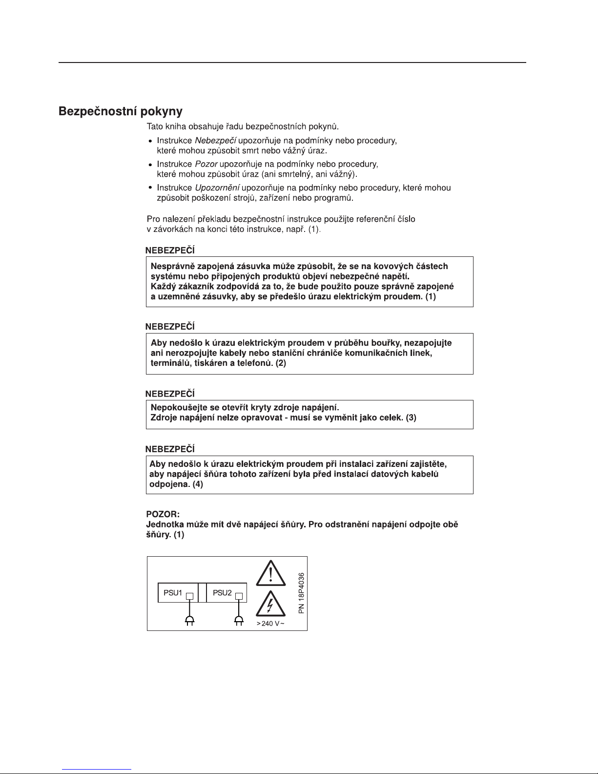
Czech
40 IBM TotalStorage SAN Switch: 2109 Model F16 User’s Guide
SJCZE329
Page 61
SJCZE332
Appendix D. Translated safety notices 41
Page 62

Danish
42 IBM TotalStorage SAN Switch: 2109 Model F16 User’s Guide
SJDAN329
Page 63
SJDAN332
Appendix D. Translated safety notices 43
Page 64

Dutch
44 IBM TotalStorage SAN Switch: 2109 Model F16 User’s Guide
Page 65
SJDUT332
Appendix D. Translated safety notices 45
Page 66

Finnish
46 IBM TotalStorage SAN Switch: 2109 Model F16 User’s Guide
SJFIN329
Page 67

SJFIN332
Appendix D. Translated safety notices 47
Page 68

French
48 IBM TotalStorage SAN Switch: 2109 Model F16 User’s Guide
SJFRE329
Page 69

SJFRE332
Appendix D. Translated safety notices 49
Page 70

German
50 IBM TotalStorage SAN Switch: 2109 Model F16 User’s Guide
SJGER329
Page 71

SJGER332
Appendix D. Translated safety notices 51
Page 72
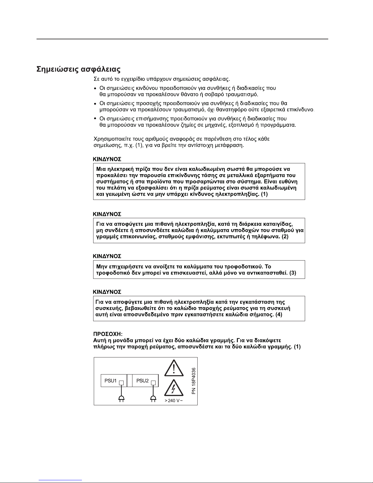
Greek
52 IBM TotalStorage SAN Switch: 2109 Model F16 User’s Guide
SJGRE329
Page 73

SJGRE332
Appendix D. Translated safety notices 53
Page 74

Hebrew
54 IBM TotalStorage SAN Switch: 2109 Model F16 User’s Guide
Page 75

SJHEB332
Appendix D. Translated safety notices 55
Page 76

Hungarian
56 IBM TotalStorage SAN Switch: 2109 Model F16 User’s Guide
Page 77
SJHUN332
Appendix D. Translated safety notices 57
Page 78

Italian
58 IBM TotalStorage SAN Switch: 2109 Model F16 User’s Guide
SJITA329
Page 79

SJITA332
Appendix D. Translated safety notices 59
Page 80

Japanese
60 IBM TotalStorage SAN Switch: 2109 Model F16 User’s Guide
SJJPN329
Page 81

SJJPN332
Appendix D. Translated safety notices 61
Page 82

Korean
62 IBM TotalStorage SAN Switch: 2109 Model F16 User’s Guide
SJKOR329
Page 83

SJKOR332
Appendix D. Translated safety notices 63
Page 84

Macedonian
64 IBM TotalStorage SAN Switch: 2109 Model F16 User’s Guide
SJMAC329
Page 85

ВНИМАНИЕ:
Во САД користете само GBIC единици или Фибер-оптички продукти
кои се во согласност со FDA стандардите за ради¼аци¼а, CFR
подзаглавие £. Интернационално користете само GBIC единици или
Фибер-оптички продукти кои се во согласност со IEC стандард 825-1.
Оптичките продукти кои не се во согласност со овие стандарди може
да предизвикаат светлина штетна за очите. (2)
ВНИМАНИЕ:
Контролерската картица содржи литиумска батери¼а. За да не до¼де
до експлози¼а, не ¼а горете, не ¼а заменува¼те, не ¼а полнете батери¼ата.
При фрлаœе на контролерската картица постапете според локалните
регулативи за литиумски батерии. (4)
SJMAC332
Appendix D. Translated safety notices 65
Page 86

Portuguese
66 IBM TotalStorage SAN Switch: 2109 Model F16 User’s Guide
SJPOR329
Page 87

SJPOR332
Appendix D. Translated safety notices 67
Page 88

Russian
68 IBM TotalStorage SAN Switch: 2109 Model F16 User’s Guide
SJRUS329
Page 89

SJRUS332
Appendix D. Translated safety notices 69
Page 90

Slovak
70 IBM TotalStorage SAN Switch: 2109 Model F16 User’s Guide
SJSLK329
Page 91

SJSLK332
Appendix D. Translated safety notices 71
Page 92

Slovenian
72 IBM TotalStorage SAN Switch: 2109 Model F16 User’s Guide
SJSLV329
Page 93

SJSLV332
Appendix D. Translated safety notices 73
Page 94

Spanish
74 IBM TotalStorage SAN Switch: 2109 Model F16 User’s Guide
SJSPA329
Page 95

SJSPA332
Appendix D. Translated safety notices 75
Page 96

Swedish
76 IBM TotalStorage SAN Switch: 2109 Model F16 User’s Guide
Page 97

SJSWE332
Appendix D. Translated safety notices 77
Page 98

78 IBM TotalStorage SAN Switch: 2109 Model F16 User’s Guide
Page 99

Notices
This information was developed for products and services offered in the U. S. A.
IBM may not offer the products, services, or features discussed in this document in
other countries. Consult your local IBM representative for information on the
products and services currently available in your area. Any reference to an IBM
product, program, or service is not intended to state or imply that only that IBM
product, program, or service may be used. Any functionally equivalent product,
program, or service that does not infringe on any IBM intellectual property right may
be used instead. However, it is the user’s responsibility to evaluate and verify the
operation of any non-IBM product, program, or service.
IBM may have patents or pending patent applications covering subject matter
described in this document. The furnishing of this document does not give you any
license to these patents. You can send license inquiries, in writing to:
IBM Director of Licensing
IBM Corporation
North Castle Drive
Armonk, N.Y. 10504–1785
U.S.A.
The following paragraph does not apply to the United Kingdom or any other
country where such provisions are inconsistent with local law:
INTERNATIONAL BUSINESS MACHINES CORPORATION PROVIDES THIS
PUBLICATION “AS IS” WITHOUT WARRANTY OF ANY KIND, EITHER EXPRESS
OR IMPLIED, INCLUDING, BUT NOT LIMITED TO, THE IMPLIED WARRANTIES
OF NON-INFRINGEMENT, MERCHANTABILITY OR FITNESS FOR A
PARTICULAR PURPOSE. Some states do not allow disclaimer of express or
implied warranties in certain transactions, therefore, this statement may not apply to
you.
This information could include technical inaccuracies or typographical errors.
Changes are periodically made to the information herein; these changes will be
incorporated in new editions of the publication. IBM may make improvements and/or
changes in the product(s) and/or the program(s) described in this publication at any
time without notice.
Any references in this information to non-IBM Web sites are provided for
convenience only and do not in any manner serve as an endorsement of those
Web sites. The materials at those Web sites are not part of the materials for this
IBM product and use of those Web sites is at your own risk.
IBM may use or distribute any of the information you supply in any way it believes
appropriate without incurring any obligation to you.
© Copyright IBM Corp. 2001, 2003 79
Page 100

Trademarks
The following terms are trademarks of the International Business Machines
Corporation in the United States, other countries, or both:
IBM
TotalStorage
Intel is a registered trademark of Intel Corporation in the United States, other
countries, or both.
Other company, product, or service names may be trademarks or service marks of
others.
Electronic emission statements
This section gives the electronic emission notices or statements for the United
States and other countries.
Federal Communications Commission (FCC) statement
This equipment has been tested and found to comply with the limits for a class A
digital device, pursuant to Part 15 of the FCC Rules. These limits are designed to
provide reasonable protection against harmful interference when the equipment is
operated in a commercial environment. This equipment generates, uses, and can
radiate radio frequency energy and, if not installed and used in accordance with the
instruction manual, may cause harmful interference to radio communications.
Operation of this equipment in a residential area is likely to cause harmful
interference, in which case the user will be required to correct the interference at
his own expense.
Properly shielded and grounded cables and connectors must be used in order to
meet FCC emission limits. IBM is not responsible for any radio or television
interference caused by using other than recommended cables and connectors or by
unauthorized changes or modifications to this equipment. Unauthorized changes or
modifications could void the user’s authority to operate the equipment.
This device complies with Part 15 of the FCC Rules. Operation is subject to the
following two conditions: (1) this device may not cause harmful interference, and (2)
this device must accept any interference received, including interference that may
cause undesired operation.
Industry Canada compliance statement
Avis de conformite a la reglementation d’Industrie Canada: Cet appareil
numerique de la classe A est conform a la norme NMB-003 du Canada.
Chinese Class A warning statement
|
|
|
Attention: This is a Class A product. In a domestic environment, this product may
cause radio interference in which case the user may be required to take adequate
measures.
80 IBM TotalStorage SAN Switch: 2109 Model F16 User’s Guide
 Loading...