

Page 1

Fibre Channel RAID Storage Server and
Expandable Storage Unit, IBM 2102
ModelF10andModelD00
Service Guide
IBM
SY27-7604-02
Page 2

Page 3

Fibre Channel RAID Storage Server and
Expandable Storage Unit, IBM 2102
ModelF10andModelD00
Service Guide
IBM
SY27-7604-02
Page 4

Take Note!
Before using this information and the product it supports, be sure to read the general information under “Notices” on page xv.
Second Edition (April 1999)
Publications are not stocked at the address given below. If you want additional IBM publications, ask your IBM
representative or write to the IBM branch office serving your locality.
A form for reader’s comments is provided at the back of this publication. If the form has been removed, address your
comments to:
International Business Machines Corporation
RCF Processing Department
Dept G26/Bldg. 050-3
5600 Cottle Road
SAN JOSE, CA 95193-0001
U.S.A.
You can also send your comments electronically to:
When you send information to IBM, you grant IBM a nonexclusive right to use or distribute the information in any
way it believes appropriate without incurring any obligation to you.
© Copyright International Business Machines Corporation 1999. All rights reserved.
US Government Users Restricted Rights – Use duplication or disclosure restricted by GSA ADP Schedule Contract
with IBM Corp.
Page 5

Contents
Figures ........................... xi
Notices ...........................xv
Safety and Environmental Notices .................xv
Safety Notices........................ xv
Environmental Notices and Statements ..............xvi
Electronic Emission Statements ..................xvi
Federal Communications Commission (FCC) Statement ........xvi
Industry Canada Compliance Statement ..............xvii
European Community Compliance Statement ............xvii
Germany Only........................xvii
Japanese Voluntary Control Council for Interference (VCCI) Class A
Statement ........................xviii
Korean Government Ministry of Communication (MOC) Statement ....xviii
Taiwan Class A Compliance Statement...............xviii
Trademarks..........................xviii
IBM License Agreement for Machine Code .............xxi
Statements of Limited Warranty .................xxiii
Production Status .......................xxiii
The IBM Warranty for Machines ..................xxiii
Warranty Service........................xxiv
Extent of Warranty .......................xxiv
Limitation of Liability ......................xxv
About This Book .......................xxvii
Who Should Use This Book....................xxvii
Related Publications ......................xxvii
Web Site...........................xxvii
Part 1. Maintenance Starting Points...................... 1
Chapter 1. Maintenance Starting Points .............. 3
2102 Fibre Channel RAID Storage Server Start Tables .......... 4
Start Table A ........................ 4
Start Table B ........................ 8
Start Table C ........................11
Start Table D ........................13
AIX Error Codes (SRNs) .....................15
The Error Code Table .....................15
Using the Error Code Table ...................15
Location Codes Displayed By Diagnostics .............31
Part 2. Installation and Removal .......................33
Chapter 2. Installation And Removal Guide .............35
Preparatory Tasks .......................35
Tools and Equipment You May Need ...............35
About the Installation Procedure .................35
Preparing the Site .......................36
Floor Space ........................36
© Copyright IBM Corp. 1999 iii
Page 6

Heating and Air Conditioning ..................38
Electrical..........................39
Interface Connectors and Cables .................41
Preparing the Rackmount Cabinet .................43
Cabinet Preparation Task List ..................43
Installing the Support Rails ....................44
About Support Rails......................44
Instructions .........................44
Installing the Controller Module ..................45
Tools and Equipment .....................45
Instructions .........................45
Installing the Drive Module ....................49
Tools and Equipment .....................49
Instructions .........................49
Configuring the Controller Module .................54
Completing the Installation ....................56
Start-up Notes........................56
Configuration Notes......................56
Starting Up the Subsystem ...................56
Verifying the Installation ....................58
Removal ...........................59
LVD-SCSI Drive Cable Routing Examples ..............59
Drive Cabling Example A....................59
Drive Cabling Example B....................60
Drive Cabling Example C....................61
Drive Cabling Example D....................62
Drive Cabling Example E....................63
Drive Cabling Example F ....................64
Part 3. Controller Module Service Guide ...................67
Chapter 3. Getting Started....................69
Identifying the Parts.......................69
Controller Module Cabinets ...................69
Removable Components ....................69
Internal Components .....................70
Basic Operation ........................72
Gaining Access to the Controls .................72
Turning On the Power .....................72
Turning Off the Power .....................74
Restoring Power .......................74
Using the Status LEDs.....................75
Instructions for Modifying the Controller Module ............78
Preparing to Move the Controller Module ..............79
Removing and Installing FRUs..................79
Removing the Module from the Rackmount Cabinet ..........81
Disassembling and Reassembling the Chassis ............83
Chapter 4. Controllers .....................87
Overview...........................87
General Description......................87
Identifying Interface Problems ...................87
Types of Interface Problems...................87
Hints for Troubleshooting Interface Problems ............88
Controller FRU ........................89
Controller Description .....................89
iv IBM 2102 Model F10 and Model D00 Service Guide
Page 7

Controller Specifications ....................91
Controller Servicing Notes ...................91
Troubleshooting Controller Problems ...............92
Replacing a Failed Controller ..................93
Controller Backpanel ......................96
Controller Backpanel Description .................96
Controller Backpanel Specifications ................97
Controller Backpanel Servicing Notes ...............97
Troubleshooting Controller Backpanel Problems ...........97
Replacing a Failed Controller Backpanel ..............98
Chapter 5. Cooling System ...................101
Overview of Cooling System ...................101
General Description......................101
Servicing the Cooling System ...................101
Preserving Proper Air Flow ...................102
Determining Which Fan Failed ..................102
Controller Fan FRU .......................103
Controller Fan Description ...................103
Controller Fan Specifications ..................104
Controller Fan Servicing Notes..................105
Troubleshooting Controller Fan Problems..............105
Replacing a Failed Controller Fan ................106
Power Supply Fan FRU .....................107
Power Supply Fan Description ..................107
Power Supply Fan ......................108
Power Supply Fan Servicing Notes ................109
Troubleshooting Power Supply Fan Problems ............109
Replacing a Failed Power Supply Fan ...............109
Chapter 6. Power System ....................111
Overview of Power System ....................111
General Description......................111
Servicing the Power System ...................111
Types of Power System Problems ................112
Hardware-Related Problems ..................112
Battery FRU .........................112
Battery Description ......................112
Battery Specifications .....................113
Battery Servicing Notes ....................113
Troubleshooting Battery Problems ................114
Checking the Battery Service Date ................115
Replacing the Battery FRU ...................116
Power Supply FRU .......................118
Power Supply Description ...................118
Power Supply Specifications ..................119
Power Supply Recovery Notes..................119
Troubleshooting Power Supply Problems ..............120
Recovering from a Power Supply Shutdown .............121
Replacing a Failed Power Supply.................122
Battery Harness ........................123
Battery Harness Description...................123
Battery Harness Specifications..................124
Battery Harness Servicing Notes .................124
Troubleshooting Battery Harness Problems .............125
Replacing the Battery Harness..................125
Contents v
Page 8

DC Power Harnesses ......................126
DC Power Harness Description .................126
DC Power Harness Specifications ................127
DC Power Harness Servicing Notes................127
Troubleshooting DC Power Harness Problems ............127
Replacing the DC Power Harnesses................128
Power Interface Board......................130
Power Interface Board Description ................130
Power Interface Specifications ..................130
Power Interface Board Servicing Notes ..............130
Troubleshooting Power Interface Board Problems...........131
Replacing a Controller Module Chassis ..............131
Chapter 7. Reference......................133
Troubleshooting Quick Reference..................133
Controller and Interface Problems ................133
Cooling Problems ......................135
Power Problems .......................136
Part 4. Drive Module Service Guide ......................139
Chapter 8. Getting Started with the Drive Module...........141
What is the Drive Module? ....................141
Basic Components .......................142
Front View .........................142
Back View .........................142
About the Drives ........................143
Front Panel.........................143
Drive FRUs.........................144
Drive Numbering .......................144
Drive Capacities .......................145
About the SCSI Components ...................146
Environmental Services Monitor Board ...............146
Mid-Plane .........................148
Interface Cables .......................149
About the Power System .....................149
Power Supply FRUs .....................149
About the Cooling System ....................151
Fan FRUs .........................151
Moving The Drives .......................151
Chapter 9. Operating the Drive Module...............153
Basic Operation ........................153
Controls on the Front .....................153
Controls on the Back .....................153
Turn On the Power ......................153
Turn Off the Power ......................154
Perform an Emergency Shutdown ................155
Restore Power After an Emergency ................156
Checking the Drive Module ....................156
Status LEDs ........................156
Check the Overall Hardware Status ................156
Chapter 10. Servicing the Drives .................159
Disk Drive Overview ......................159
General Notes........................159
vi IBM 2102 Model F10 and Model D00 Service Guide
Page 9

Drive Failure Notes ......................160
Maintaining the Drives ......................160
Replace a Failed Drive ....................160
Identify Other Drive-Related Problems ...............164
Chapter 11. Servicing the SCSI Components ............167
SCSI Component Overview ....................167
Servicing SCSI Components ..................167
Maintaining the SCSI Components .................168
Types of Interface Problems...................168
Hints for Troubleshooting Interface Problems ............169
Replace a SCSI Interface Cable .................169
Replace a Failed ESM FRU...................170
Replace a Failed MidPlane ...................173
Chapter 12. Servicing the Power System ..............179
Power System Overview .....................179
Power Supply Servicing Notes ..................179
Power Supply Recovery Notes..................179
Maintaining the Power System...................180
Types of Power System Problems ................180
Recover from a Power Supply Shutdown ..............180
Replace a Failed Power Supply .................183
Chapter 13. Servicing the Cooling System .............187
Cooling System Overview ....................187
Fan Servicing Notes .....................187
Maintaining the Cooling Fans ...................187
Replace a Failed Fan .....................188
Chapter 14. Technical Reference .................191
Technical Specifications .....................191
Factory Settings .......................191
Hardware Features ......................192
Software Features ......................192
Interface Connections and Cables .................193
Drive Module Interface Connections................193
Host SCSI Interface Connections.................193
SCSI Cables ........................194
Host SCSI Pin Assignments and Signals ..............194
SCSI Drive Pin Assignments and Signals ..............195
Chapter 15. Quick References ..................197
Drive Module Parts .......................197
Drive Module Troubleshooting Chart.................198
Part 5. Debugging Tools and Procedures ...................203
Chapter 16. RAID Manager for DOS ................205
What is RAID Manager for DOS?..................205
When to Use RAID Manager for DOS ................205
Menu Options Summary .....................206
Task Summary ........................208
PC Requirements and Preparation Tasks ...............208
PC Requirements ......................208
Preparation Tasks ......................209
Contents vii
Page 10

Changing DRM Boot Up Defaults (Floppy Drive and COM Port) ......210
Using DRM with a Monochrome Display ...............210
Connecting to the Controller Locally.................210
Starting DRM .........................211
Verifying the Installation .....................212
Using the Array Configuration Editor (ACE) ..............212
Starting ACE ........................213
The Logical Unit Window ....................214
The Drive Window ......................216
Navigating in ACE ......................221
Identifying Drives and Logical Units ................222
Identify the Controller or Change the Name .............222
Scan the Bus for Array Devices .................222
Using the Array Monitor ....................223
Diagnostics .........................225
Changing the Password ....................226
Display and Set the Battery Age .................226
Checking Array Status.....................226
Chapter 17. Installing the Remote Support Feature ..........229
Remote Support Attachment of the WTI Data Switch and Modem ......229
Remote Support Feature Initial Installation .............229
Chapter 18. Drive Microcode Download ..............239
Downloading Drive Microcode from Windows NT using DriveDload .....239
What is DriveDload? .....................239
When to Use DriveDload ....................239
Installing DriveDload .....................239
Starting DriveDload ......................240
Using DriveDload ......................240
Drive Mode Page Download...................243
Downloading Drive Microcode from HP-UX or SUN Solaris Using drvDLoad . . 244
What is drvDLoad? ......................244
When to Use drvDLoad ....................244
Installing drvDLoad ......................244
Starting drvDLoad ......................245
Using drvDLoad .......................245
Downloading Drive Microcode From An AIX Host ............246
Chapter 19. Controller Debug Shell ................247
Accessing the Controller Debug Shell ................247
Controller Debug Shell Commands .................248
Summary of Common Debug Shell Commands ...........248
Part 6. Appendixes .............................251
Appendix A. AIX Code Information ................253
2102-F10 Error Log Sense Information................253
Field Replaceable Unit (FRU) Codes ................258
Additional FRU Information ....................258
Disk Array Errors........................260
2102 Array Additional Sense Codes And Qualifiers (ASC/ASQ) .......261
Appendix B. Safety Inspection Procedure..............269
Appendix C. Safety Inspection Procedure in German .........273
viii IBM 2102 Model F10 and Model D00 Service Guide
Page 11

Appendix D. Safety Inspection Procedure in Traditional Chinese.....277
Appendix E. Fibre Channel RAID Storage Server and Expandable Storage
Unit Parts Catalog ......................281
2102 Model F10 Controller Module FRUs...............282
2102 Model D00 Drive Module FRUs ................286
Glossary ..........................289
Index ............................291
Readers’ Comments — We’d Like to Hear from You..........309
Contents ix
Page 12

x IBM 2102 Model F10 and Model D00 Service Guide
Page 13

Figures
1. Controller Module Dimensions .................37
2. Dimensions of Drive Module..................38
3. Interface Connections on Controller Module ............41
4. Media Interface Adapter (MIA) .................42
5. Rackmount Cabinet .....................43
6. Removable Covers on the Controller Module............46
7. Removing The FRUs ....................46
8. Removing The FRUs – cont...................47
9. Removing The FRUs – cont...................47
10. Chassis Mounting on Support Rails ...............48
11. Interface Connections on a Rackmount Controller Module .......49
12. Removing the Drive Module FRUs ...............50
13. Removing the Drive Module FRUs – cont..............51
14. Tray ID and Option Switches .................53
15. Connecting Interface Cables and Power Cords ...........54
16. Setting the Fibre Host IDs ..................55
17. Controller Module Power Cords and Power Switches.........57
18. Drive Module Power Switches .................57
19. Rackmount Cabling to One Drive Module .............60
20. Rackmount Cabling to Two Drive Modules ............61
21. Rackmount Cabling to Three Drive Modules ............62
22. Rackmount Cabling to Four Drive Modules ............63
23. Rackmount Cabling to Five Drive Modules ............64
24. Rackmount Cabling to Six Drive Modules .............65
25. Rackmount Cabinet .....................69
26. Front View of Controller Module ................70
27. Back View of Controller Module ................70
28. Internal Components ....................71
29. Internal Components – cont...................71
30. Removable Cover on the Controller Module ............72
31. Controller Module Power Switches ...............73
32. LEDs on the Front .....................76
33. LEDs on the Back .....................78
34. Removing and Installing FRUs .................80
35. Removing and Installing FRUs – cont. ..............80
36. Removing and Installing FRUs – cont. ..............81
37. Disconnecting Interface Cables.................82
38. Removing and Installing the Chassis on Support Rails ........82
39. Removing and Replacing the Cover Plate.............83
40. Removing Screws, Harnesses, and Power Supply Assembly ......84
41. DC Battery and Power Harness Connections ...........85
42. Removing the Controller Card Cage ...............85
43. Controller FRUs in Controller Module ..............87
44. Controller FRU, Slots and LEDs ................89
45. Controller FRU, Slots and LEDs – cont. .............90
46. LEDs on Front Covers ....................93
47. Removing and Installing a Controller FRU.............95
48. Controller Card Cage ....................96
49. Controller Module Cooling System ...............101
50. Air Flow through Chassis ...................102
51. Controller Module Fan Fault LEDs ...............103
52. Controller Fan FRU and Status LEDs ..............104
53. Removing and Installing a Controller Fan .............107
© Copyright IBM Corp. 1999 xi
Page 14

54. Power Supply Fan FRU ...................108
55. Removing and Installing a Power Supply Fan FRU .........110
56. Controller Module Power System FRUs .............111
57. Battery FRU........................113
58. Removing and Replacing a Front Cover .............115
59. Battery FRU Service Label ..................116
60. Removing and Installing the Battery FRU .............117
61. Power Supply FRU .....................119
62. Fault Indicators for a Failed Power Supply ............122
63. Turning Off the Power and Unplugging the Power Cord........123
64. Removing and Installing a Power Supply FRU ...........123
65. Battery Harness ......................124
66. Removing and Installing a Battery Harness ............126
67. DC Power Harnesses ....................127
68. Reconnecting the DC Power Harnesses .............129
69. Power Supply Assembly ...................130
70. Drive Module .......................141
71. Front Views of the Drive Module ................142
72. Back View of the Drive Module.................143
73. Drive LEDs ........................144
74. Drive FRU ........................144
75. Drive Channel and SCSI ID Numbering..............145
76.ESMFRU........................146
77. ESM Board Connectors, Switches, and LEDs ...........147
78. Location of Mid-Plane ....................149
79. Power Supply FRU .....................150
80.FanFRU.........................151
81. Power Cords and Switches ..................154
82. Drive LEDs on the Front Panel.................157
83. LEDs on Drive Module with ESM Board .............158
84. Drive FRU and Front Panel LEDs................162
85. Removing/Installing Drive FRUs ................163
86. Amber Fault LEDs (Rackmount) ................171
87. Power Switches, Power Cords, and SCSI Interface Cables ......172
88. Removing/Installing an ESM FRU................173
89. Power Switches, Power Cords, and SCSI Cables ..........175
90. Removing/Installing Power Supplies and Interface FRUs .......175
91. Removing/Installing Drive and Fan FRUs .............176
92. Rear Mounting Screws ....................177
93. Front Mounting Screws....................177
94. Fault LEDs on the Back of the Drive Module............181
95. Fault LEDs on the Back of the Drive Module............184
96. Power Switches and Power Cords ...............185
97. Removing/Installing a Power Supply FRU .............186
98. Fault LEDs on the Back of the Drive Module............189
99. Removing/Installing a Fan FRU ................190
100. RAID Manager for DOS Main Menu ...............212
101. The Array Configuration Editor (ACE) Display ...........213
102. The Logical Unit window ...................214
103. The Logical Unit Status Display ................215
104. The Drive window .....................217
105. The Drive Matrix ......................218
106. Device Drawer with Single Drive Bus (Bridge Disable OFF) ......218
107. Device Drawer with 2 Drive Buses (Bridge Disable ON)........219
108. Attachment of the Modem and WTI Switch to a IBM 2102 F10 Fibre
Channel Storage Server ...................229
xii IBM 2102 Model F10 and Model D00 Service Guide
Page 15

109. Help Menu. ........................231
110. Port Configuration Menu ...................232
111. Port Configuration Menu ...................233
112. Help Menu. ........................237
113. DriveDload Main Menu....................241
114. 2102 Model F10 Controller Module FRUs .............282
115. 2102 Model F10 Controller Module FRUs – cont. ..........283
116. 2102 Model F10 Controller Module FRUs – cont. ..........284
117. 2102 Model D00 Drive Module FRUs ..............286
Figures xiii
Page 16

xiv IBM 2102 Model F10 and Model D00 Service Guide
Page 17

Notices
References in this publication to IBM products, programs, or services do not imply
that IBM intends to make these available in all countries in which IBM operates. Any
reference to an IBM product, program, or service is not intended to state or imply
that only that IBM product, program, or service may be used. Subject to IBM’s valid
intellectual property or other legally protected rights, any functionally equivalent
product, program, or service, may be used instead of the IBM product, program, or
service. The evaluation and verification of operation in conjunction with other
products, except those expressly designated by IBM, are the responsibility of the
user.
IBM may have patents or pending patent applications covering subject matter in this
document. The furnishing of this document does not give you any license to these
patents. You can send license inquiries, in writing, to:
IBM Director of Licensing
IBM Corporation
North Castle Drive
Armonk, NY 10504-1785
U.S.A.
Read Before Using
IMPORTANT
YOU ACCEPT THE TERMS OF THIS IBM LICENSE AGREEMENT FOR
MACHINE CODE BY YOUR USE OF THE HARDWARE PRODUCT OR
MACHINE CODE. PLEASE READ THE AGREEMENT CONTAINED IN THIS
BOOK BEFORE USING THE HARDWARE PRODUCT. SEE “IBM License
Agreement for Machine Code” on page xxi.
Safety and Environmental Notices
This section contains information about:
v Safety notices used in this guide
v Environmental notices and statements for this product
Safety Notices
Note: For a translation of the danger and caution notices, see
Notices for Open Attachment
Definitions of Safety Notices
DANGER
A danger notice indicates the presence of a hazard that has the potential of
causing death or serious personal injury.
Translated Safety
, GC26-7246.
CAUTION:
A caution notice indicates the presence of a hazard that has the potential of
causing minor or moderate personal injury.
© Copyright IBM Corp. 1999 xv
Page 18

CAUTION:
The drawer weighs approximately 25 kg (55 lb) with no devices installed. Do
not try to lift it by yourself. Ask another service representative for assistance.
CAUTION:
Energy hazard, remove power before servicing.
CAUTION:
This unit weighs between 18 kg (39.7 pounds) and 32 kg (70.5 pounds). Two
persons are required to safely move it. Using less than two persons to move
it can result in injury.
Attention: An attention notice indicates the possibility of damage to a program,
device, system or data.
Translations of the Safety Inspection Procedure
See “Appendix C. Safety Inspection Procedure in German” on page 273 and
“Appendix D. Safety Inspection Procedure in Traditional Chinese” on page 277 for
the German and Chinese translations of “Appendix B. Safety Inspection Procedure”
on page 269.
Environmental Notices and Statements
Product Disposal
This product contains a SEALED LEAD ACID BATTERY. When the battery
assembly is replaced, the used battery assembly must be returned to IBM for
proper disposal.
Product Recycling
This unit contains recyclable materials. These materials should be recycled where
processing sites are available and according to local regulations. In some areas
IBM provides a product take-back program that ensures proper handling of the
product. Contact your IBM representative for more information.
Electronic Emission Statements
This section gives the electronic emission notices or statements for the United
States and other countries.
Federal Communications Commission (FCC) Statement
This equipment has been tested and found to comply with the limits for a Class A
digital device, pursuant to Part 15 of the FCC Rules. These limits are designed to
provide reasonable protection against harmful interference when the equipment is
operated in a commercial environment. This equipment generates, uses, and can
radiate radio frequency energy and, if not installed and used in accordance with the
instruction manual, may cause harmful interference to radio communications.
Operation of this equipment in a residential area is likely to cause harmful
interference, in which case the user will be required to correct the interference at
his own expense.
xvi IBM 2102 Model F10 and Model D00 Service Guide
Page 19

Properly shielded and grounded cables and connectors must be used in order to
meet FCC emission limits. IBM is not responsible for any radio or television
interference caused by using other than recommended cables and connectors or by
unauthorized changes or modifications to this equipment. Unauthorized changes or
modifications could void the user’s authority to operate the equipment.
This device complies with Part 15 of the FCC Rules. Operation is subject to the
following two conditions: (1) this device may not cause harmful interference, and (2)
this device must accept any interference received, including interference that may
cause undesired operation.
Industry Canada Compliance Statement
This Class A digital apparatus complies with Canadian ICES-003.
Avis de conformité à la réglementation d’Industrie Canada: Cet appareil
numérique de la classe A est conform à la norme NMB-003 du Canada.
European Community Compliance Statement
This product is in conformity with the protection requirements of EC Council
Directive 89/336/EEC on the approximation of the laws of the Member States
relating to electromagnetic compatibility. IBM cannot accept responsibility for any
failure to satisfy the protection requirements resulting from a non-recommended
modification of the product, including the fitting of non-IBM option cards.
Germany Only
Zulassungsbescheinigung laut Gesetz ueber die elektromagnetische
Vertraeglichkeit von Geraeten (EMVG) vom 30. August 1995.
Dieses Geraet ist berechtigt, in Uebereinstimmung mit dem deutschen EMVG das
EG-Konformitaetszeichen - CE - zu fuehren.
Der Aussteller der Konformitaetserklaeung ist die IBM Deutschland.
Informationen in Hinsicht EMVG Paragraph 3 Abs. (2) 2:
Das Geraet erfuellt die Schutzanforderungen nach EN 50082-1 und
EN 55022 Klasse A.
EN 55022 Klasse A Geraete beduerfen folgender Hinweise:
Nach dem EMVG:
"Geraete duerfen an Orten, fuer die sie
nicht ausreichend entstoert
sind, nur mit besonderer Genehmigung des Bundesministeriums
fuer Post und Telekommunikation oder des Bundesamtes fuer Post und
Telekommunikation
betrieben werden. Die Genehmigung wird erteilt, wenn keine
elektromagnetischen Stoerungen zu erwarten sind." (Auszug aus dem
EMVG, Paragraph 3, Abs.4)
Dieses Genehmigungsverfahren ist nach Paragraph 9 EMVG in Verbindung
mit der entsprechenden Kostenverordnung (Amtsblatt 14/93)
kostenpflichtig.
Nach der EN 55022:
Notices xvii
Page 20
"Dies ist eine Einrichtung der Klasse A. Diese Einrichtung kann im
Wohnbereich Funkstoerungen verursachen. in diesem Fall kann vom
Betreiber verlangt werden, angemessene Massnahmen durchzufuehren
und dafuer aufzukommen."
Anmerkung:
Um die Einhaltung des EMVG sicherzustellen, sind die Geraete wie in den
Handbuechern angegeben zu installieren und zu betreiben.
Japanese Voluntary Control Council for Interference (VCCI) Class A
Statement
Korean Government Ministry of Communication (MOC) Statement
Please note that this device has been approved for business purposes with regard
to electromagnetic interference. If you find this is not suitable for your use, you may
exchange it for one with a non-business purpose.
Taiwan Class A Compliance Statement
Trademarks
The following terms are trademarks of the International Business Machines
Corporation in the United States or other countries or both:
IBM
Seascape
StorWatch
HP-UX and Hewlett-Packard are trademarks of Hewlett-Packard Company.
Sun, SPARC, SunOS, and Solaris, are trademarks of Sun Microsystems, Inc.
xviii IBM 2102 Model F10 and Model D00 Service Guide
Page 21

Windows NT and Alpha Windows NT are trademarks of Microsoft Corporation.
UNIX is a registered trademark in the United States and other countries licensed
exclusively through X/Open Company Limited.
Other company, product, or service names, may be trademarks or service marks of
others.
Notices xix
Page 22

xx IBM 2102 Model F10 and Model D00 Service Guide
Page 23

IBM License Agreement for Machine Code
Regardless of how you acquire (electronically, preloaded, on media or otherwise)
BIOS, Utilities, Diagnostics, Device Drivers or Microcode (collectively called
“Machine Code”), you accept the terms of this Agreement by your initial use of a
Machine or Machine Code. The term “Machine” means an IBM machine, its
features, conversions, upgrades, elements or accessories, or any combination of
them. Acceptance of these license terms authorizes you to use Machine Code with
the specific product for which it is provided.
International Business Machines Corporation or one of its subsidiaries (“IBM”), or an
IBM supplier, owns copyrights in Machine Code.
IBM grants you a nonexclusive license to use Machine Code only in conjunction
with a Machine. As the rightful possessor of a Machine, you may make a
reasonable number of copies of Machine Code as necessary for backup,
configuration, and restoration of the Machine. You must reproduce the copyright
notice and any other legend of ownership on each copy of Machine Code you
make.
You may transfer possession of Machine Code and its media to another party only
with the transfer of the Machine on which the Machine Code is used. If you do so,
you must give the other party a copy of these terms and provide all user
documentation to that party. When you do so, you must destroy all your copies of
Machine Code.
Your license for Machine Code terminates when you no longer rightfully possess the
Machine.
No other rights under this license are granted.
You may not, for example, do any of the following:
1. otherwise copy, display, transfer, adapt, modify, or distribute in any form,
Machine Code, except as IBM may authorize in a Machine’s user
documentation.
2. reverse assemble, reverse compile, or otherwise translate the Machine Code,
unless expressly permitted by applicable law without the possibility of
contractual waiver;
3. sublicense or assign the license for the Machine Code; or
4. lease the Machine Code or any copy of it.
The terms of IBM’s Machine warranty, which is incorporated into this Agreement by
reference, apply to Machine Code. Please refer to that warranty for any questions
or claims regarding performance or liability for Machine Code.
© Copyright IBM Corp. 1999 xxi
Page 24

xxii IBM 2102 Model F10 and Model D00 Service Guide
Page 25

Statements of Limited Warranty
International Business Machines Corporation
Armonk, New York, 10504
The warranties provided by IBM in this Statement of Limited Warranty1apply only to
Machines you originally purchase for your use, and not for resale, from IBM or your
reseller. The term “Machine” means an IBM machine, its features, conversions,
upgrades, elements, or accessories, or any combination of them.
Unless IBM specifies otherwise, the following warranties apply only in the country
where you acquire the Machine. If you have any questions, contact IBM or your
reseller.
Machine: IBM Fibre Channel RAID Storage Server and
Warranty Period: One Year*
* Contact your place of purchase for warranty service information.
Production Status
Each Machine is manufactured from new parts, or new and used parts. In some
cases, the Machine may not be new and may have been previously installed.
Regardless of the Machine’s production status, IBM’s warranty terms apply.
Expandable Storage Unit
2102 Model F10 and 2102 Model D00
The IBM Warranty for Machines
IBM warrants that each Machine 1) is free from defects in materials and
workmanship and 2) conforms to IBM’s Official Published Specifications. The
warranty period for a Machine is a specified, fixed period commencing on its Date
of Installation. The date on your receipt is the Date of Installation, unless IBM or
your reseller informs you otherwise.
During the warranty period IBM or your reseller, if authorized by IBM, will provide
warranty service under the type of service designated for the Machine and will
manage and install engineering changes that apply to the Machine.
For IBM or your reseller to provide warranty service for a feature, conversion, or
upgrade, IBM or your reseller may require that the Machine on which it is installed
be 1) for certain Machines, the designated, serial-numbered Machine and 2) at an
engineering-change level compatible with the feature, conversion, or upgrade. Many
of these transactions involve the removal of parts and their return to IBM. You
represent that all removed parts are genuine and unaltered. A part that replaces a
removed part will assume the warranty service status of the replaced part.
If a Machine does not function as warranted during the warranty period, IBM or your
reseller will repair it or replace it with one that is at least functionally equivalent,
without charge. The replacement may not be new, but will be in good working order.
1. Form Z125-4753
© Copyright IBM Corp. 1999
xxiii
Page 26

If IBM or your reseller is unable to repair or replace the Machine, you may return it
to your place of purchase and your money will be refunded.
If you transfer a Machine to another user, warranty service is available to that user
for the remainder of the warranty period. You should give your proof of purchase
and this Statement to that user. However, for Machines which have a lifetime
warranty, this warranty is not transferable.
Warranty Service
To obtain warranty service for the Machine, you should contact your reseller or call
IBM. In the United States, call IBM at 1-800-IBM-SERV (426-7378) In Canada, call
IBM at 1-800-465-6666. You may be required to present proof of purchase.
IBM or your reseller will provide certain types of repair and exchange service, either
at your location or at IBM’s or your reseller’s service center, to restore a Machine to
good working order.
When a type of service involves the exchange of a Machine or part, the item IBM or
your reseller replaces becomes its property and the replacement becomes yours.
You represent that all removed items are genuine and unaltered. The replacement
may not be new, but will be in good working order and at least functionally
equivalent to the item replaced. The replacement assumes the warranty service
status of the replaced item. Before IBM or your reseller exchanges a Machine or
part, you agree to remove all features, parts, options, alterations, and attachments
not under warranty service. You also agree to ensure that the Machine is free of
any legal obligations or restrictions that prevent its exchange.
You agree to:
1. obtain authorization from the owner to have IBM or your reseller service a
2. where applicable, before service is provided:
IBM is responsible for loss of, or damage to, your Machine while it is 1) in IBM’s
possession or 2) in transit in those cases where IBM is responsible for the
transportation charges.
Extent of Warranty
IBM does not warrant uninterrupted or error-free operation of a Machine.
The warranties may be voided by misuse, accident, modification, unsuitable
physical or operating environment, improper maintenance by you, removal or
alteration of Machine or parts identification labels, or failure caused by a product for
which IBM is not responsible.
THESE WARRANTIES REPLACE ALL OTHER WARRANTIES OR CONDITIONS,
EXPRESS OR IMPLIED, INCLUDING, BUT NOT LIMITED TO, THE IMPLIED
WARRANTIES OR CONDITIONS OF MERCHANTABILITY AND FITNESS FOR A
Machine that you do not own; and
a. follow the problem determination, problem analysis, and service request
procedures that IBM or your reseller provide,
b. secure all programs, data, and funds contained in a Machine, and
c. inform IBM or your reseller of changes in a Machine’s location.
xxiv IBM 2102 Model F10 and Model D00 Service Guide
Page 27

PARTICULAR PURPOSE. THESE WARRANTIES GIVE YOU SPECIFIC LEGAL
RIGHTS AND YOU MAY ALSO HAVE OTHER RIGHTS WHICH VARY FROM
JURISDICTION TO JURISDICTION. SOME JURISDICTIONS DO NOT ALLOW
THE EXCLUSION OR LIMITATION OF EXPRESS OR IMPLIED WARRANTIES, SO
THE ABOVE EXCLUSION OR LIMITATION MAY NOT APPLY TO YOU. IN THAT
EVENT SUCH WARRANTIES ARE LIMITED IN DURATION TO THE WARRANTY
PERIOD. NO WARRANTIES APPLY AFTER THAT PERIOD.
Limitation of Liability
Circumstances may arise where, because of a default on IBM’s part or other liability
you are entitled to recover damages from IBM. In each such instance, regardless of
the basis on which you are entitled to claim damages from IBM (including
fundamental breach, negligence, misrepresentation, or other contract or tort claim),
IBM is liable only for:
1. damages for bodily injury (including death) and damage to real property and
tangible personal property; and
2. the amount of any other actual direct damages or loss, up to the greater of U.S.
$100,000 or the charges (if recurring, 12 months’ charges apply) for the
Machine that is the subject of the claim.
UNDER NO CIRCUMSTANCES IS IBM LIABLE FOR ANY OF THE FOLLOWING:
1) THIRD-PARTY CLAIMS AGAINST YOU FOR LOSSES OR DAMAGES (OTHER
THAN THOSE UNDER THE FIRST ITEM LISTED ABOVE); 2) LOSS OF, OR
DAMAGE TO, YOUR RECORDS OR DATA; OR 3) SPECIAL, INCIDENTAL, OR
INDIRECT DAMAGES OR FOR ANY ECONOMIC CONSEQUENTIAL DAMAGES
(INCLUDING LOST PROFITS OR SAVINGS), EVEN IF IBM OR YOUR RESELLER
IS INFORMED OF THEIR POSSIBILITY. SOME JURISDICTIONS DO NOT ALLOW
THE EXCLUSION OR LIMITATION OF INCIDENTAL OR CONSEQUENTIAL
DAMAGES, SO THE ABOVE EXCLUSION OR LIMITATION MAY NOT APPLY TO
YOU.
Statements of Limited Warranty xxv
Page 28

xxvi IBM 2102 Model F10 and Model D00 Service Guide
Page 29

About This Book
This book provides the information for servicing the IBM Fibre Channel RAID
Storage Server with the Expandable Storage Unit.
Who Should Use This Book
This publication is for Service Representatives who are installing and maintaining
the 2102 subsystem.
Related Publications
Additional information that is related to the subsystem is available in the following
publications:
Seascape Solution Rack, Installation and Service Guide, IBM 2101 Model 100
v
SY27-7606
v
Fibre Channel RAID Storage Server, Introduction and Planning Guide, IBM 2102
GC26-7281
Fibre Channel Storage Manager, Installation Guide for Microsoft Windows NT
v
SC26-7283
v
StorWatch Fibre Channel RAID Specialist, Installation Guide for Microsoft
Windows NT and Windows 95
v
Fibre Channel Storage Manager and StorWatch Fibre Channel RAID Specialist,
User’s Guide
Fibre Channel Storage Manager, Installation Guide for Sun Solaris Operating
v
System
v
Fibre Channel Storage Manager, Installation Guide for Hewlett Packard HP-UX
Operating System
v
Fibre Channel RAID Storage Server and Expandable Storage Unit, User’s Guide,
IBM 2102 Model F10 and Model D00
v
Fibre Channel Storage Hub, Installation, Service, and User’s Guide, IBM 2103
Model H07
v
Fibre Channel Storage Manager, Installation and User’s Guide for the AIX
Operating System
v
Diagnostic Information for Multiple Bus Systems
, SC26-7285
, SC26-7286
, SC26-7289
,
,
,
, SC26-7284
, SC26-7287
, SC26-7288
, SC26-7290
, SA38-0509
Additional publications are available for purchase from IBM. For a list of publications
available in your country:
v In the U.S. and Puerto Rico, call 1–800–426–7282.
v In the United Kingdom, call 01705–565000 or 0161–9056001.
v In Canada, call 1–800–465–1234.
v In other countries, contact the IBM support organization that services your area,
your IBM marketing representative, or your IBM reseller.
Web Site
For more Fibre Channel Storage information, go to
http://www.ibm.com/storage/fcss on the World Wide Web.
© Copyright IBM Corp. 1999 xxvii
Page 30

xxviii IBM 2102 Model F10 and Model D00 Service Guide
Page 31

Part 1. Maintenance Starting Points
© Copyright IBM Corp. 1999 1
Page 32

2 IBM 2102 Model F10 and Model D00 Service Guide
Page 33

Chapter 1. Maintenance Starting Points
The following four tables contain pointers into the 2102 subsystem maintenance
package. Before using the tables, be sure to consult the Installation and/or User’s
Guide for the storage management software specific to the operating system being
used. In many cases, these Guides contain procedures for analyzing and repairing
problems from the host that provide better isolation and the most up-to-date
recovery steps. Throughout this guide, the term ″storage management software″ is
used generically to refer to the Fibre Channel Storage Manager software and its
related components running on a Windows NT, SUN Solaris, HP-UX or AIX host
platform.
v For subsystems attached to a Windows NT host, refer to
Manager and StorWatch Fibre Channel RAID Specialist, User’s Guide
SC26-7285 and
Windows NT
v For subsystems attached to an HP-UX host, refer to
Manager and StorWatch Fibre Channel RAID Specialist, User’s Guide
SC26-7285 and
Packard HP-UX Operating System
v For subsystems attached to a SUN Solaris host, refer to
Manager and StorWatch Fibre Channel RAID Specialist, User’s Guide
SC26-7285 and
Solaris Operating System
v For subsystems attached to an AIX host, refer to
Manager, Installation and User’s Guide for the AIX Operating System
SC26-7290.
v For subsystems using a networked storage management station running
StorWatch Fibre Channel RAID Specialist, refer to
Manager and StorWatch Fibre Channel RAID Specialist, User’s Guide
SC26-7285 and
Microsoft Windows NT and Windows 95
Fibre Channel Storage Manager, Installation Guide for Microsoft
, SC26-7283.
Fibre Channel Storage Manager, Installation Guide for Hewlett
, SC26-7287.
Fibre Channel Storage Manager, Installation Guide for Sun
, SC26-7286.
StorWatch Fibre Channel RAID Specialist, Installation Guide for
Fibre Channel Storage
,
Fibre Channel Storage
,
Fibre Channel Storage
,
Fibre Channel Storage
,
Fibre Channel Storage
,
, SC26-7284.
If you are unable to resolve the problem using the software guides or you cannot
find the appropriate information, then use these START tables. To use the tables,
find the reason you are here in the left column and then perform the action in the
right column.
After completing a recovery procedure (especially hardware replacement), you
should verify the subsystem status using the host software:
v If the subsystem is attached to a Windows NT, SUN, or HP-UX host system
running the Fibre Channel Storage Manager software or a Windows NT or
Windows 95 system running the StorWatch Fibre Channel RAID Specialist
software, then run the Recovery Guru to verify that the subsystem is operating
properly. Refer to
RAID Specialist, User’s Guide
v If the subsystem is attached to an AIX host, then run the Advanced Diagnostics
in System Verification mode from the diagnostic interface (type ″diag″ from the
command prompt) to verify that the subsystem is operating properly. Refer to
Fibre Channel Storage Manager and StorWatch Fibre Channel
, SC26-7285.
Fibre Channel Storage Manager, Installation and User’s Guide for the AIX
Operating System
Systems
customer to normal operation).
© Copyright IBM Corp. 1999 3
, SA38-0509 for more information (refer to MAP 0410 for returning the
, SC26-7290 and
Diagnostic Information for Multiple Bus
Page 34

2102 Fibre Channel RAID Storage Server Start Tables
Start Table A
Table 1. 2102 Fibre Channel RAID Storage Server Start Table A
If you are here for this
reason...
Running diagnostics from an
AIX host resulted in a six digit
Service Request Number/Error
Code
...Then perform this action
Go to “AIX Error Codes (SRNs)” on page 15.
4 IBM 2102 Model F10 and Model D00 Service Guide
Page 35

Table 1. 2102 Fibre Channel RAID Storage Server Start Table A (continued)
If you are here for this
...Then perform this action
reason...
v A check light is active on a
subsystem component
v A problem occurred during
an installation procedure
v The host software indicated
that a problem occurred
within the RAID array
subsystem
v The customer observed a
problem that was not
detected or reported by the
host system
v You suspect a problem
within the RAID array
subsystem
Controller:
1. If the subsystem is attached to a Windows NT, SUN, or HP-UX host system
running the
Windows 95 system running the
Fibre Channel Storage Manager
StorWatch Fibre Channel RAID Specialist
software, then run the Recovery Guru from the host system and follow the
recovery procedures given. Refer to
Fibre Channel Storage Manager and
StorWatch Fibre Channel RAID Specialist, User’s Guide
2. If the subsystem is attached to an AIX host, then run Advanced Diagnostics in
Problem Determination mode from the diagnostic interface (type ″diag″ from the
command prompt). If the diagnostics return an error code for the 2102
subsystem, then go to “AIX Error Codes (SRNs)” on page 15 and follow the
instructions for the error code generated. Once the problem has been addressed,
rerun the AIX Advanced Diagnostics in System Verification mode to verify the
repair. Refer to
the AIX Operating System
Bus Systems
Fibre Channel Storage Manager, Installation and User’s Guide for
, SC26-7290 and
, SA38-0509 (MAP 0410) for more information.
3. If you don’t have access to the host system or the host system does not provide
a recovery procedure or error code, then follow these steps in order:
a. Go to “Troubleshooting Controller Problems” on page 92 and follow the
procedure for the matching symptoms. If no symptoms match, go to the next
step.
b. Go to “Troubleshooting Controller Fan Problems” on page 105 and follow the
procedure for the matching symptoms. If no symptoms match, go to the next
step.
c. Go to “Identifying Interface Problems” on page 87 and follow the procedure for
debugging interface problems. If this does not fix the problem, go to the next
step.
d. Go to “Troubleshooting Power Supply Problems” on page 120 and follow the
procedure for the matching symptoms. If no symptoms match, go to the next
step.
e. Go to “Troubleshooting Battery Problems” on page 114 and follow the
procedure for the matching symptoms. If no symptoms match, go to the next
step.
f. Go to “Troubleshooting Controller Backpanel Problems” on page 97 and follow
the procedure for the matching symptoms. If no symptoms match, go to the
next step.
g. Go to “Troubleshooting Battery Harness Problems” on page 125 and follow
the procedure for the matching symptoms. If no symptoms match, go to the
next step.
h. Go to “Troubleshooting DC Power Harness Problems” on page 127 and follow
the procedure for the matching symptoms. If no symptoms match, go to the
next step.
i. Go to “Troubleshooting Power Interface Board Problems” on page 131 and
follow the procedure for the matching symptoms. If no symptoms match, go to
the next step.
j. Call your next level of support.
software or a Windows NT or
, SC26-7285.
Diagnostic Information for Multiple
Chapter 1. Maintenance Starting Points 5
Page 36

Table 1. 2102 Fibre Channel RAID Storage Server Start Table A (continued)
If you are here for this
reason...
Continued from page 5.
...Then perform this action
Device Drawer:
1. If the subsystem is attached to a Windows NT, SUN, or HP-UX host system
running the
Windows 95 system running the
software, then run the Recovery Guru from the host system and follow the
recovery procedures given. Refer to
Fibre Channel Storage Manager
StorWatch Fibre Channel RAID Specialist
Fibre Channel Storage Manager and
StorWatch Fibre Channel RAID Specialist, User’s Guide
2. If the subsystem is attached to an AIX host, then run Advanced Diagnostics in
Problem Determination mode from the diagnostic interface (type ″diag″ from the
command prompt). If the diagnostics return an error code for the 2102
subsystem, then go to “AIX Error Codes (SRNs)” on page 15 and follow the
instructions for the error code generated. Once the problem has been addressed,
rerun the AIX Advanced Diagnostics in System Verification mode to verify the
repair. Refer to
the AIX Operating System
Bus Systems
3. If you don’t have access to the host system or the host system does not provide
a recovery procedure or error code, then follow these steps in order:
a. Go to “Maintaining the Drives” on page 160 and follow the problem
identification procedures given. If this does not fix the problem, go to the next
step.
b. Go to “Identify Other Drive-Related Problems” on page 164 and follow the
problem identification procedures given. If this does not fix the problem, go to
the next step.
c. Go to “Maintaining the SCSI Components” on page 168 and follow the
problem identification procedures given. If this does not fix the problem, go to
the next step.
d. Go to “Maintaining the Power System” on page 180 and follow the problem
identification procedures given. If this does not fix the problem, go to the next
step.
e. Go to “Drive Module Troubleshooting Chart” on page 198 and follow the
problem identification procedures given. If this does not fix the problem, go to
the next step.
f. Call your next level of support.
Fibre Channel Storage Manager, Installation and User’s Guide for
, SC26-7290 and
, SA38-0509 (MAP 0410) for more information.
software or a Windows NT or
, SC26-7285.
Diagnostic Information for Multiple
6 IBM 2102 Model F10 and Model D00 Service Guide
Page 37

Table 1. 2102 Fibre Channel RAID Storage Server Start Table A (continued)
If you are here for this
reason...
Continued from page 5
. Hub:
...Then perform this action
1. If the subsystem is attached to a Windows NT, SUN, or HP-UX host system
running the
Windows 95 system running the
software, then run the Recovery Guru from the host system and follow the
recovery procedures given. Refer to the
Fibre Channel Storage Manager
StorWatch Fibre Channel RAID Specialist
StorWatch Fibre Channel RAID Specialist, User’s Guide
2. If the subsystem is attached to an AIX host, then run Advanced Diagnostics in
Problem Determination mode from the diagnostic interface (type ″diag″ from the
command prompt). If the diagnostics return an error code for the 2102
subsystem, then go to “AIX Error Codes (SRNs)” on page 15 and follow the
instructions for the error code generated. Once the problem has been addressed,
rerun the AIX Advanced Diagnostics in System Verification mode to verify the
repair. Refer to
the AIX Operating System
Bus Systems
3. If you don’t have access to the host system or the host system does not provide
a recovery procedure or error code, then follow these steps in order:
a. Go to ″Troubleshooting″ in
Fibre Channel Storage Manager, Installation and User’s Guide for
, SC26-7290 and
, SA38-0509 (MAP 0410) for more information.
Fibre Channel Storage Hub, Installation, Service,
and User’s Guide, IBM 2103 Model H07
identification procedures given. If this does not fix the problem, go to the next
step.
b. Go to ″Connect the Cables″ in
Fibre Channel Storage Hub, Installation,
Service, and User’s Guide, IBM 2103 Model H07
problem identification procedures given. If this does not fix the problem, go to
the next step.
c. Call your next level of support.
software or a Windows NT or
Fibre Channel Storage Manager and
, SC26-7285.
Diagnostic Information for Multiple
, SC26-7289 and follow the problem
, SC26-7289 and follow the
Rack:
Go to
Seascape Solution Rack, Installation and Service Guide, IBM 2101 Model 100
SY27-7606 and follow the appropriate procedure for debugging rack problems. If you
cannot fix the problem following the procedures in
Installation and Service Guide, IBM 2101 Model 100
level of support.
Seascape Solution Rack,
, SY27-7606, then call your next
,
Chapter 1. Maintenance Starting Points 7
Page 38

Start Table B
Table 2. 2102 Fibre Channel RAID Storage Server Start Table B
If you are here for this
reason...
Replace FRUs in the Controller
Module
...Then perform this action
Controller Card Go to “Replacing a Failed Controller” on page 93
Battery Go to “Replacing the Battery FRU” on page 116
Backpanel Go to “Replacing a Failed Controller Backpanel”
Controller Fan Go to “Replacing a Failed Controller Fan” on
Power Supply Go to “Replacing a Failed Power Supply” on
Power Supply Fan Go to “Replacing a Failed Power Supply Fan” on
on page 98
page 106
page 122
page 109
Replace FRUs in the Device
Drawer
Replace FRUs in the Fibre
Channel Hub
Drive Go to “Replace a Failed Drive” on page 160
ESM board Go to “Replace a Failed ESM FRU” on page 170
Fan Go to “Replace a Failed Fan” on page 188
Power Supply Go to “Replace a Failed Power Supply” on
page 183
Refer to
2103 Model H07
Fibre Channel Storage Hub, Installation, Service, and User’s Guide, IBM
, SC26-7289.
8 IBM 2102 Model F10 and Model D00 Service Guide
Page 39

Table 2. 2102 Fibre Channel RAID Storage Server Start Table B (continued)
If you are here for this
...Then perform this action
reason...
Power On/Off Subsystem
Components
Note: Subsystem components must be powered up in the correct sequence to
ensure proper operation.
Power Up Sequence:
1. rack (ensure that power for attached subsystem components is off)
2. hub
3. device drawers
4. controller module
5. host (wait until all drives have spun up to speed)
Power Off Sequence:
1. host (if applicable)
2. controller module
3. device drawers
4. hub
5. rack
Component Power On/Off Procedures:
rack Rack power is active when each Power
Distribution Unit (PDU) power cord is plugged in.
A green light on the PDU indicates that power is
active to that PDU. Each PDU should be
powered on before continuing.
hub Hub power is active when the hub power cord is
plugged in.
Device Drawer Wait at least 30 seconds after powering off a
device drawer before turning power back on. Turn
on both power switches on the back of the
drawer. An LED on the back of the ESM board
indicates that power is active. Refer to “Turn On
the Power” on page 153 and “Turn Off the Power”
on page 154 for details.
Controller Module Turn on/off both power switches on the back of
the module. An LED on the front panel indicates
that power is active. Refer to “Turning On the
Power” on page 72 and “Turning Off the Power”
on page 74.
host See your host system documentation
Chapter 1. Maintenance Starting Points 9
Page 40

Table 2. 2102 Fibre Channel RAID Storage Server Start Table B (continued)
If you are here for this
reason...
The host cannot communicate
with one or both of the
controllers, but there is no LED
indication of any subsystem
faults.
...Then perform this action
1. Go to “Identifying Interface Problems” on page 87 and follow the procedure for
the debugging of interface problems. If this fails to solve the problem, then go to
Step 2.
2. Connect a service terminal to the top serial port on the back of the controller
module and start RAID Manager for DOS (DRM). See “Chapter 16. RAID
Manager for DOS” on page 205 for information on setting up and starting DRM.
3. Using DRM, run the Array Monitor utility to check the current status of array
components and verify the communication paths within the array subsystem.
Follow the procedure in “Verifying the Installation” on page 212.
v If the Array Monitor indicates a component failure within the array, then replace
the failed component.
v If the Array Monitor runs without indicating a failure (that is, it displays the
message ″Waiting for Next Polling Period″), then go to Step 4.
4. Using DRM, run the Array Configuration Editor (ACE) to verify the
communications between the controllers and the devices and check the status of
the devices.
a. If ACE indicates that the controller is not communicating over a specific drive
channel (that is, the Drive Window in ACE shows no devices on channel 6,
but there is a SCSI cable connected to channel 6 on the back of the
controller module), then replace the SCSI cable connected to that channel.
b. If ACE indicates that the controller is not communicating with a specific drive
or indicates a failure on a specific drive, then replace the defective drive.
c. If ACE indicates a problem with LUN 0 or LUN 0 is not optimal, then you must
fix the problem with LUN 0 in order to enable communication with the host. If
the problem cannot be fixed by replacing hardware, you may need to delete
and recreate LUN 0. If you do this, all data on LUN 0 will be lost. Make sure
the customer is aware of your actions and call your next level of support for
assistance.
Note: One possible case of an off-line LUN 0 can occur when a drive drawer
containing LUN 0 configuration information is added to an existing subsystem.
In this case, the subsystem has conflicting information about the LUN 0
configuration and you must remove and rebuild the LUN.
d. If ACE does not indicate any failures or communications problems, then go to
Step 5.
5. Repeat steps 2 through 5 using the bottom serial port on the back of the
controller module.
6. There is a problem with the Fibre Channel host adapter or in the fibre channel
path between the host and the subsystem. Perform the following steps:
a. Recheck the fibre channel cables between the host and the controller and
replace if necessary.
b. If there is a hub in the fibre channel path, verify that there are no failures in
the hub. See
Guide, IBM 2103 Model H07
c. Verify that the host fibre channel adapter is configured properly.
d. Verify that the host fibre channel adapter is at the correct firmware level.
e. Verify that the host fibre channel adapter is working properly and replace if
necessary. If the subsystem is attached to a system running AIX, run
diagnostics from the host on the fibre channel adapter to check for problems.
For information on running diagnostics on the adapter refer to
Fibre Channel Storage Hub, Installation, Service, and User’s
, SC26-7289 for details.
Information for Multiple Bus Systems
Diagnostic
, SA38-0509.
10 IBM 2102 Model F10 and Model D00 Service Guide
Page 41

Start Table C
Table 3. 2102 Fibre Channel RAID Storage Server Start Table C
If you are here for this
reason...
Use Fibre Channel Storage
Manager for AIX
Download Controller Firmware The controller firmware download function is provided by the host storage
Update Controller NVSRAM The update controller NVSRAM function is provided by the host storage management
Download Drive Firmware The drive firmware download function is provided by a software utility that runs on
Configure the Subsystem The subsystem configuration functions are provided by the
...Then perform this action
See
Fibre Channel Storage Manager, Installation and User’s Guide for the AIX
Operating System
management software:
v If the subsystem is attached to a Windows NT, SUN, or HP-UX host system
running the
Windows 95 system running the
software, then upgrade the controller firmware using the Maintenance and Tuning
Application. Refer to
Channel RAID Specialist, User’s Guide
v If the subsystem is attached to an AIX host system, then upgrade the controller
firmware using the AIX Diagnostic Service Aids (″Fibre Channel RAID Tasks″).
Refer to the
AIX Operating System
software:
v If the subsystem is attached to a Windows NT, SUN, or HP-UX host system
running the
Windows 95 system running the
software, then update the controller NVSRAM using the Maintenance and Tuning
application. Refer to
Channel RAID Specialist, User’s Guide
v If the subsystem is attached to an AIX host system, then upgrade the controller
firmware using the AIX Diagnostic Service Aids (″Fibre Channel RAID Tasks″).
Refer to
Operating System
the host system:
v For Windows NT host systems, refer to “Downloading Drive Microcode from
Windows NT using DriveDload” on page 239.
v For SUN Solaris or HP-UX host systems, refer to “Downloading Drive Microcode
from HP-UX or SUN Solaris Using drvDLoad” on page 244.
v For AIX host systems, use the AIX Diagnostic Service Aids (″Fibre Channel RAID
Tasks″). Refer to
for the AIX Operating System
, SC26-7290.
Fibre Channel Storage Manager
software or a Windows NT or
StorWatch Fibre Channel RAID Specialist
Fibre Channel Storage Manager and StorWatch Fibre
, SC26-7285.
Fibre Channel Storage Manager, Installation and User’s Guide for the
, SC26-7290.
Fibre Channel Storage Manager
software or a Windows NT or
StorWatch Fibre Channel RAID Specialist
Fibre Channel Storage Manager and StorWatch Fibre
, SC26-7285.
Fibre Channel Storage Manager, Installation and User’s Guide for the AIX
, SC26-7290.
Fibre Channel Storage Manager, Installation and User’s Guide
, SC26-7290.
Fibre Channel Storage
Manager
system for the appropriate procedure.
software running on the host. Refer to the software documentation for your
Chapter 1. Maintenance Starting Points 11
Page 42

Table 3. 2102 Fibre Channel RAID Storage Server Start Table C (continued)
If you are here for this
reason...
Check the Status of Subsystem
Components
...Then perform this action
Subsystem component status can be checked from the host using the status
functions provided by the host storage management software. Component status
may also be checked using a service tool connected to the controller module via the
RS232 port.
v If the subsystem is attached to a Windows NT, SUN, or HP-UX host system
running the
Windows 95 system running the
software, then run the Status application from the host system. Refer to
Fibre Channel Storage Manager
StorWatch Fibre Channel RAID Specialist
Channel Storage Manager and StorWatch Fibre Channel RAID Specialist, User’s
Guide
, SC26-7285.
v If the subsystem is attached to an AIX host system, then follow the procedures in
the
Fibre Channel Storage Manager, Installation and User’s Guide for the AIX
Install the Subsystem or
Subsystem Components
Operating System
v To check the subsystem component status from the service tool, go to “Using the
Array Monitor” on page 223.
subsystem Go to “Chapter 2. Installation And Removal
hub Go to ″Rack Installation″ in
, SC26-7290 for checking the status of subsystem components.
Guide” on page 35.
Storage Hub, Installation, Service, and User’s
Guide, IBM 2103 Model H07
drive modules Go to “Installing the Drive Module” on page 49.
controller module Go to “Installing the Controller Module” on
page 45.
software or a Windows NT or
Fibre
Fibre Channel
, SC26-7289
Use RAID Manager for DOS
(DRM)
Decipher LEDs
Go to “Chapter 16. RAID Manager for DOS” on page 205
hub Go to ″Port Status LEDs″ in
Fibre Channel
Storage Hub, Installation, Service, and User’s
Guide, IBM 2103 Model H07
device drawer and drives Go to “Check the Overall Hardware Status” on
page 156.
controller module Go to “Using the Status LEDs” on page 75.
, SC26-7289
12 IBM 2102 Model F10 and Model D00 Service Guide
Page 43

Start Table D
Table 4. 2102 Fibre Channel RAID Storage Server Start Table D
If you are here for this
reason...
Check Cables Refer to the following sections for cable locations and debug procedures:
...Then perform this action
hub
v For an example of proper GBIC and fiber optic cable installation, see ″Installing
the GBIC″ in
IBM 2103 Model H07
v For an example of a host bus adapter with a GBIC attached, see ″Attaching a
GBIC to Initiators and Targets″ in
and User’s Guide, IBM 2103 Model H07
v For GBIC and cable debug procedures, see ″Troubleshooting″ in
Fibre Channel Storage Hub, Installation, Service, and User’s Guide,
, SC26-7289.
Fibre Channel Storage Hub, Installation, Service,
, SC26-7289.
Fibre Channel
Storage Hub, Installation, Service, and User’s Guide, IBM 2103 Model H07
SC26-7289.
Device Drawer
v For SCSI connector locations on the ESM board, see “Environmental Services
Monitor Board” on page 146.
v For SCSI cable installation and routing information, see “LVD-SCSI Drive Cable
Routing Examples” on page 59.
v For SCSI cable technical information, see “Interface Connections and Cables” on
page 193.
v For SCSI cable troubleshooting procedures, see “Hints for Troubleshooting
Interface Problems” on page 169.
,
Identify Subsystem
Components
Controller Module
v For controller interface connector locations, see “Interface Connectors and Cables”
on page 41
v For cable troubleshooting hints, see “Controller and Interface Problems” on
page 133.
v If the subsystem is attached to a Windows NT, SUN, or HP-UX host system
running the
Windows 95 system running the
software, then you can identify disk drives, drive groups and logical units using the
Configuration application. Refer to
Fibre Channel RAID Specialist, User’s Guide
v If the subsystem is attached to an AIX host system, then follow the procedures in
the ″Problem Determination and Recovery″ chapter of
Manager, Installation and User’s Guide for the AIX Operating System
for identifying subsystem components.
v The disk drives that comprise a particular Logical Unit (LUN) can also be identified
by using a service tool that is connected to the controller module via the RS232
port. See “Identifying Drives and Logical Units” on page 222 for details.
Fibre Channel Storage Manager
StorWatch Fibre Channel RAID Specialist
Fibre Channel Storage Manager and StorWatch
software or a Windows NT or
, SC26-7285.
Fibre Channel Storage
, SC26-7290
Chapter 1. Maintenance Starting Points 13
Page 44

Table 4. 2102 Fibre Channel RAID Storage Server Start Table D (continued)
If you are here for this
reason...
View Message or Error Logs Message and error logs are maintained on the host system. Refer to the host system
Perform a Health Check
Perform a Parity Check/Repair The Parity Check/Repair function scans a logical unit, checks the array parity for
...Then perform this action
documentation for information on accessing and analyzing the system logs.
v The Fibre Channel Storage Manager software for Windows NT, Sun Solaris and
HP-UX, and the StorWatch Fibre Channel RAID Specialist software for Windows
NT or Windows 95 also maintains a separate message log that can be viewed
from within the status application. Refer to
StorWatch Fibre Channel RAID Specialist, User’s Guide
v On AIX host systems, the error and message logging is integrated with operating
system error log. The AIX operating system contain functions for analyzing the
system log and indicating the appropriate recovery actions. Refer to
Storage Manager, Installation and User’s Guide for the AIX Operating System
SC26-7290 and
more information.
v If the subsystem is attached to a Windows NT, SUN, or HP-UX system running the
Fibre Channel Storage Manager software or a Windows NT or Windows 95 system
running the StorWatch Fibre Channel RAID Specialist software, then you can
perform an immediate health check by using the Recovery application. There is
also a background array monitor that checks the subsystem component status at
intervals defined by the operator. Refer to
Diagnostic Information for Multiple Bus Systems
StorWatch Fibre Channel RAID Specialist, User’s Guide
information.
v On subsystems attached to an AIX host, the passive controller health check
provides monitoring capability for testing components that are not actively in use.
The health check frequency can be set from in the Disk Array Router
configuration. Refer to
Fibre Channel Storage Manager, Installation and User’s
Guide for the AIX Operating System
each block in the LUN and repairs any parity errors found.
Fibre Channel Storage Manager and
, SC26-7285.
Fibre Channel
,
, SA38-0509 for
Fibre Channel Storage Manager and
, SC26-7285 for more
, SC26-7290 for more information.
Note: If array parity errors result from corrupted data, the data is not repaired. Only
the array parity is changed to be consistent with the data.
The parity Check/Repair function can be initiated from the host using the host
storage management software.
v If the subsystem is attached to a Windows NT, SUN, or HP-UX system running the
Fibre Channel Storage Manager
running the
parity check/repair from the Recovery application. Refer to the
StorWatch Fibre Channel RAID Specialist
software or a Windows NT or Windows 95 system
software, then you can run a
Fibre Channel
Storage Manager and StorWatch Fibre Channel RAID Specialist, User’s Guide
SC26-7285.
v If the subsystem is attached to an AIX host system, then you can run the parity
Certify a LUN or a Spare
Physical Disk
check/repair from the Disk Array menu. Refer to
Installation and User’s Guide for the AIX Operating System
information.
The Certify function checks a LUN or disk for defective sectors. This service is only
available from the Diagnostic Service Aids menu on AIX host systems. Refer to
Fibre Channel Storage Manager,
, SC26-7290 for more
Channel Storage Manager, Installation and User’s Guide for the AIX Operating
System
, SC26-7290 for more information.
Format a Failed Physical Disk If the subsystem is attached to a system running AIX, use Format service aid
provided by AIX diagnostics. For details, refer to
Installation and User’s Guide for the AIX Operating System
Fibre Channel Storage Manager,
, SC26-7290.
,
Fibre
14 IBM 2102 Model F10 and Model D00 Service Guide
Page 45

Table 4. 2102 Fibre Channel RAID Storage Server Start Table D (continued)
If you are here for this
reason...
Revive a dead LUN
...Then perform this action
v If the subsystem is attached to a Windows NT, SUN, or HP-UX host system
running the Fibre Channel Storage Manager software or a Windows NT or
Windows 95 system running the StorWatch Fibre Channel RAID Specialist
software, then refer to the
Channel RAID Specialist, User’s Guide
LUNs.
v If the subsystem is attached to an AIX host system, then follow the procedures in
the ″Problem Determination and Recovery″ chapter of
Manager, Installation and User’s Guide for the AIX Operating System
for reviving dead LUNs.
Fibre Channel Storage Manager and StorWatch Fibre
, SC26-7285 for information on reviving
AIX Error Codes (SRNs)
Error Codes are generated for the subsystem by the system error-log analysis and
diagnostics. Error codes help you identify the cause of the problem, the failing field
replaceable units (FRUs), and the service actions that might be needed to solve the
problem.
The Error Code Table
Fibre Channel Storage
, SC26-7290
The table in this section lists the Error Codes and describes the actions you should
take. The table columns are:
EC The Error Code
FRU The FRU or FRUs that might be causing the
Description A description of the problem and the actions to take
Using the Error Code Table
Important: Do not start problem determination from the Error Code table; always
begin with the 2102 Fibre Channel RAID Storage Server Start Tables
that start on page 4.
1. Locate the Error Code in the table. If you cannot find the Error Code, then there
is a problem with the diagnostics, the microcode, or the documentation. Call
your next level of support for assistance.
2. Read carefully the ″Action″ you are instructed to perform.
FRUs until you have read through all procedures referenced in the
field. Then replace FRUs in the order they are listed in the FRU column of the
Error Code table.
Note: If the Error Code has been generated by diagnostics, and you are
instructed to use the disk array manager, you must end the diagnostics.
The disk array manager cannot run while the subsystem is in diagnostic
mode.
3. For information about the disk array manager, see the
Manager, Installation and User’s Guide for the AIX Operating System
SC26-7290.
problem
Do not exchange
″
Action
″
Fibre Channel Storage
,
Chapter 1. Maintenance Starting Points 15
Page 46

4. Normally, you will exchange only one FRU at a time, starting from the top of the
FRU list for that Error Code. Always follow the instructions given in this manual
when exchanging FRUs; a reference is given with each Error Code entry.
The first three digits of the error code indicate the type of failure or the FRU that
most likely failed, as follows:
444 Controller with 256 MB cache
555 Fan
641 DDRS-39130D 9GB Disk Drive
658 Controller with 128 MB cache
666 Power Supply
670 DGHS18D 18 GB Disk Drive
671 DGHS09D 9 GB Disk Drive
677 Fibre Channel Adapter
679 DDRS-34560D 4.5 GB Disk Drive
777 Cache Battery
888 AC Line
999 Over Temperature Indicator
Table 5. AIX Error Codes
EC FRU Description
444101
444102
444103
444104
v SCSI cables
v Controller Card - see “Replacing a
Failed Controller” on page 93.
v ESM board - see “Replace a Failed
ESM FRU” on page 170.
v Controller backpanel - see “Replacing a
Failed Controller Backpanel” on
page 98.
v Controller Card - see “Replacing a
Failed Controller” on page 93.
v Controller backpanel - see “Replacing a
Failed Controller Backpanel” on
page 98.
v Controller Card - see “Replacing a
Failed Controller” on page 93.
v Fibre Channel Adapter
v Controller backpanel - see “Replacing a
Failed Controller Backpanel” on
page 98.
v Controller Card - see “Replacing a
Failed Controller” on page 93.
v Fibre Channel Adapter
v Controller backpanel - see “Replacing a
Failed Controller Backpanel” on
page 98.
A SCSI problem was detected.
Action: Read the procedures in “Hints for Troubleshooting
Interface Problems” on page 169 for debugging SCSI interface
problems. If the problem is not resolved, then replace FRUs in
the order listed here.
One of two array controller cards failed or powered down.
Action: Read the procedure in “Troubleshooting Controller
Problems” on page 92 and, if necessary, replace the FRUs as
indicated.
The device failed to open in Diagnostic mode.
Action: Follow the procedures in “Troubleshooting Controller
Problems” on page 92 and replace FRUs as indicated.
The controller configuration failed.
Action: Follow the procedures in “Troubleshooting Controller
Problems” on page 92 and replace FRUs as indicated.
16 IBM 2102 Model F10 and Model D00 Service Guide
Page 47

Table 5. AIX Error Codes (continued)
EC FRU Description
444105
v SCSI cables
v ESM board - see “Replace a Failed
ESM FRU” on page 170.
v Device Drawer Midplane/Chassis - see
“Replace a Failed MidPlane” on
page 173.
v Controller backpanel - see “Replacing a
Failed Controller Backpanel” on
page 98.
Cannot access physical disks.
Action: Read the procedures in “Hints for Troubleshooting
Interface Problems” on page 169 for debugging SCSI interface
problems. If the problem is not resolved, then replace FRUs in
the order listed here.
Note: This error is typically caused by a SCSI interface
problem, but can also occur if there is no power to a device
drawer. This is why the device drawer power supplies are
listed in the FRUs at left.
v Controller Card - see “Replacing a
Failed Controller” on page 93.
v Device Drawer Power Supplies - see
“Replace a Failed Power Supply” on
page 183.
444106
v SCSI cables
v Disk Drive - see “Replace a Failed
Drive” on page 160.
v Controller Card - see “Replacing a
Failed Controller” on page 93
v ESM board - see “Replace a Failed
ESM FRU” on page 170.
v Controller backpanel - see “Replacing a
Failed Controller Backpanel” on
page 98.
A physical disk failed to respond.
Action: Read the procedure in “Hints for Troubleshooting
Interface Problems” on page 88 and “Hints for Troubleshooting
Interface Problems” on page 169 for debugging interface
problems and exchange SCSI cables if necessary. If the
problem persists, then refer to the procedures in “Maintaining
the Drives” on page 160 and “Identify Other Drive-Related
Problems” on page 164 for debugging drives and drive related
problems, and replace a failed disk drive if instructed. If the
problem persists, then refer to the procedures in
“Troubleshooting Controller Problems” on page 92 for
debugging controller problems and replace FRUs as
instructed.
444107
v SCSI cables
The controller failed to become active due to an inter-controller
communications failure.
v Controller Card - see “Replacing a
Failed Controller” on page 93
v Controller backpanel - see “Replacing a
Failed Controller Backpanel” on
page 98.
Action: Read the procedure in “Hints for Troubleshooting
Interface Problems” on page 88 and “Hints for Troubleshooting
Interface Problems” on page 169 for debugging interface
problems and exchange SCSI cables if necessary. If the
problem persists, then refer to the procedures in
“Troubleshooting Controller Problems” on page 92 for
debugging controller problems and replace FRUs as
instructed.
444108 Disk Drive - see “Replace a Failed Drive”
on page 160.
The controller failed to become active due to a non-supported
drive.
Action: Use the system problem determination procedures
with error log analysis to identify the failing disk drive. Then
exchange the FRU for a new FRU.
Chapter 1. Maintenance Starting Points 17
Page 48

Table 5. AIX Error Codes (continued)
EC FRU Description
444121 Any subsystem component Error Log Analysis indicates a subsystem failure.
Action: If the ELA identifies the source of the problem, then
replace the FRU(s) indicated. If the ELA does not identify the
source of the problem, then check the subsystem LEDs (see
“Using the Status LEDs” on page 75 and “Check the Overall
Hardware Status” on page 156) and go to the START table.
If the LEDs do not indicate a problem, then run Advanced
Diagnostics in System Verification mode on the controller that
reported the failure and use the SRN generated to debug the
failure.
444122
444123
444124
444125
444126
v Controller Card - see “Replacing a
Failed Controller” on page 93
v Controller backpanel - see “Replacing a
Failed Controller Backpanel” on
page 98.
v Controller Card - see “Replacing a
Failed Controller” on page 93
v Controller backpanel - see “Replacing a
Failed Controller Backpanel” on
page 98.
v SCSI cables
v Controller Card - see “Replacing a
Failed Controller” on page 93
v Controller backpanel - see “Replacing a
Failed Controller Backpanel” on
page 98.
v Fibre Channel Adapter
v Controller Card - see “Replacing a
Failed Controller” on page 93
v Controller backpanel - see “Replacing a
Failed Controller Backpanel” on
page 98.
v Fibre Channel Adapter
v Controller Card - see “Replacing a
Failed Controller” on page 93
v Controller backpanel - see “Replacing a
Failed Controller Backpanel” on
page 98.
Error Log Analysis indicates an active controller failure.
Action: Exchange the FRU for a new FRU.
Error Log Analysis indicates a passive controller failure.
Action: Exchange the FRU for a new FRU.
Error Log Analysis indicates an inter-controller communications
failure.
Action: Read the procedure in “Hints for Troubleshooting
Interface Problems” on page 88 and “Hints for Troubleshooting
Interface Problems” on page 169 for debugging interface
problems and exchange SCSI cables if necessary. If the
problem persists, then refer to the procedures in
“Troubleshooting Controller Problems” on page 92 for
debugging controller problems and replace FRUs as
instructed.
Error Log Analysis indicates that the configuration of the
controller has changed.
Action: Run Advanced Diagnostics in System Verification
Mode through the adapter and array controller for which the
problem was reported, to confirm the error. Exchange the
FRUs for new FRUs.
Error Log Analysis indicates a controller switch failure.
Action: Run Advanced Diagnostics in System Verification
Mode through the adapter and array controller for which the
problem was reported, to confirm the error. Exchange the
FRUs for new FRUs.
18 IBM 2102 Model F10 and Model D00 Service Guide
Page 49

Table 5. AIX Error Codes (continued)
EC FRU Description
555202 The list of possible failing FRUs depends
Critical fan fault. Two or more fan assemblies have failed.
on the enclosure identified in the
diagnostic failure information (See
“Location Codes Displayed By
Diagnostics” on page 31):
Controller Module (EID E0):
v Controller Fan - see “Replacing a
Failed Controller Fan” on page 106.
Action:
v For Controller Module fan failures, read the procedure in
“Servicing the Cooling System” on page 101 and replace
FRUs as instructed.
v For Drive Drawer fan failures, read the procedure in
“Maintaining the Cooling Fans” on page 187 and replace
FRUs as instructed.
v Controller Power Supply Fan - see
“Replacing a Failed Power Supply Fan”
on page 109.
v Controller Backpanel - see “Replacing
a Failed Controller Backpanel” on
page 98.
Drive Drawer (EID E2 – E6):
v Device Drawer Fan - see “Replace a
Failed Fan” on page 188.
v Device Drawer Midplane/Chassis - see
“Replace a Failed MidPlane” on
page 173.
555203 The list of possible failing FRUs depends
Enclosure status reports a non-critical fan failure.
on the enclosure identified in the
diagnostic failure information (See
“Location Codes Displayed By
Diagnostics” on page 31):
Controller Module (EID E0):
v Controller Fan - see “Replacing a
Failed Controller Fan” on page 106.
Action:
v For Controller Module fan failures, read the procedure in
“Servicing the Cooling System” on page 101 and replace
FRUs as instructed.
v For Drive Drawer fan failures, read the procedure in
“Maintaining the Cooling Fans” on page 187 and replace
FRUs as instructed.
v Controller Power Supply Fan - see
“Replacing a Failed Power Supply Fan”
on page 109.
v Controller Backpanel - see “Replacing
a Failed Controller Backpanel” on
page 98.
Drive Drawer (EID E2 – E6):
v Device Drawer Fan - see “Replace a
Failed Fan” on page 188.
v Device Drawer Midplane/Chassis - see
“Replace a Failed MidPlane” on
page 173.
641001 Disk Drive - see “Replace a Failed Drive”
on page 160.
641103 Disk Drive - see “Replace a Failed Drive”
on page 160.
A drive failed. Test Unit Ready failure.
Action: Exchange the FRU for a new FRU.
The disk drive failed due to an unknown cause.
Action: Exchange the FRU for a new FRU.
Chapter 1. Maintenance Starting Points 19
Page 50

Table 5. AIX Error Codes (continued)
EC FRU Description
641109 Disk Drive - see “Replace a Failed Drive”
on page 160.
641113 Disk Drive - see “Replace a Failed Drive”
on page 160.
641116 Disk Drive - see “Replace a Failed Drive”
on page 160.
641123 Disk Drive - see “Replace a Failed Drive”
on page 160.
641126 Disk Drive - see “Replace a Failed Drive”
on page 160.
An incorrect disk drive module was removed/replaced.
Action: If you replaced the wrong drive, but the logical unit is
not being written, then replacing the drive you removed
immediately should restore the logical unit and prevent data
loss. In other instances, you
without losing any data by ″reviving″ the drive. Call your next
level of support for direction.
Read failure.
Action: Exchange the FRU for a new FRU.
Incorrect sector size.
Action:Format the drive using the AIX Disk Array Manager. If
this fails to fix the problem, then exchange the FRU for a new
FRU.
The drive does not respond or a defined Global Hot Spare
drive is missing.
Action: Exchange the FRU for a new FRU.
Incorrect Disk capacity. The disk drive might belong to a
different logical unit.
may
be able to restore the array
641133 Disk Drive - see “Replace a Failed Drive”
on page 160.
641143 Disk Drive - see “Replace a Failed Drive”
on page 160.
641153 Disk Drive - see “Replace a Failed Drive”
on page 160.
641173 Disk Drive - see “Replace a Failed Drive”
on page 160.
641202 Disk Drive(s) - see “Replace a Failed
Drive” on page 160.
641203 Disk Drive(s) - see “Replace a Failed
Drive” on page 160.
641330 Disk Drive - see “Replace a Failed Drive”
on page 160.
Action: Format the drive using the Fibre Channel RAID
Manager. If this fails to fix the problem, then exchange the
FRU for a new FRU.
The drive failed to format or reconstruct.
Action: Exchange the FRU for a new FRU.
Write failure.
Action: Exchange the FRU for a new FRU.
The drive was failed by the user via a Mode Select.
Action: If the drive was failed for the purpose of replacing the
drive, then exchange the failed drive for a new FRU. If you
wish to revive the same drive and bring it back into the array,
then use the Fibre Channel RAID Manager to make the drive
operational.
A drive failed. Controller storage failure.
Action: Exchange the FRU for a new FRU.
Enclosure status reports a critical disk failure.
Action: Exchange the FRU for a new FRU.
Enclosure status reports a non-critical disk failure.
Action: Exchange the FRU for a new FRU.
Error Log analysis indicates predictive failure analysis.
Action: Exchange the FRU for a new FRU.
20 IBM 2102 Model F10 and Model D00 Service Guide
Page 51

Table 5. AIX Error Codes (continued)
EC FRU Description
641332 Disk Drive - see “Replace a Failed Drive”
on page 160.
Error Log Analysis indicates that the physical disk does not
support dual-active configuration.
Action: Exchange the FRU for a new FRU.
641333 Disk Drive - see “Replace a Failed Drive”
Error Log Analysis indicates a physical disk failure.
on page 160.
Action: Exchange the FRU for a new FRU.
658101
v SCSI cables
v Controller Card - see “Replacing a
Failed Controller” on page 93.
v ESM board - see “Replace a Failed
ESM FRU” on page 170.
A SCSI problem was detected.
Action: Read the procedures in “Hints for Troubleshooting
Interface Problems” on page 169 for debugging SCSI interface
problems. If the problem is not resolved, then replace FRUs in
the order listed here.
v Controller backpanel - see “Replacing a
Failed Controller Backpanel” on
page 98.
658102
v Controller Card - see “Replacing a
Failed Controller” on page 93.
v Controller backpanel - see “Replacing a
Failed Controller Backpanel” on
One of two array controller cards failed or powered down.
Action: Read the procedure in “Troubleshooting Controller
Problems” on page 92 and, if necessary, replace the FRUs as
indicated.
page 98.
658103
v Controller Card - see “Replacing a
Failed Controller” on page 93.
v Fibre Channel Adapter
The device failed to open in Diagnostic mode.
Action: Follow the procedures in “Troubleshooting Controller
Problems” on page 92 and replace FRUs as indicated.
v Controller backpanel - see “Replacing a
Failed Controller Backpanel” on
page 98.
658104
v Controller Card - see “Replacing a
Failed Controller” on page 93.
v Fibre Channel Adapter
The controller configuration failed.
Action: Follow the procedures in “Troubleshooting Controller
Problems” on page 92 and replace FRUs as indicated.
v Controller backpanel - see “Replacing a
Failed Controller Backpanel” on
page 98.
658105
v SCSI cables
v ESM board - see “Replace a Failed
ESM FRU” on page 170.
v Device Drawer Midplane/Chassis - see
“Replace a Failed MidPlane” on
page 173.
v Controller backpanel - see “Replacing a
Failed Controller Backpanel” on
page 98.
Cannot access physical disks.
Action: Read the procedures in “Hints for Troubleshooting
Interface Problems” on page 169 for debugging SCSI interface
problems. If the problem is not resolved, then replace FRUs in
the order listed here.
Note: This error is typically caused by a SCSI interface
problem, but can also occur if there is no power to a device
drawer. This is why the device drawer power supplies are
listed in the FRUs at left.
v Controller Card - see “Replacing a
Failed Controller” on page 93.
v Device Drawer Power Supplies - see
“Replace a Failed Power Supply” on
page 183.
Chapter 1. Maintenance Starting Points 21
Page 52

Table 5. AIX Error Codes (continued)
EC FRU Description
658106
658107
658108 Disk Drive - see “Replace a Failed Drive”
v Disk Drive - see “Replace a Failed
Drive” on page 160.
v SCSI cables
v Controller Card - see “Replacing a
Failed Controller” on page 93
v ESM board - see “Replace a Failed
ESM FRU” on page 170.
v Controller backpanel - see “Replacing a
Failed Controller Backpanel” on
page 98.
v SCSI cables
v Controller Card - see “Replacing a
Failed Controller” on page 93
v Controller backpanel - see “Replacing a
Failed Controller Backpanel” on
page 98.
on page 160.
A physical disk failed to respond.
Action: Read the procedure in “Hints for Troubleshooting
Interface Problems” on page 88 and “Hints for Troubleshooting
Interface Problems” on page 169 for debugging interface
problems and exchange SCSI cables if necessary. If the
problem persists, then refer to the procedures in “Maintaining
the Drives” on page 160 and “Identify Other Drive-Related
Problems” on page 164 for debugging drives and drive related
problems, and replace a failed disk drive if instructed. If the
problem persists, then refer to the procedures in
“Troubleshooting Controller Problems” on page 92 for
debugging controller problems and replace FRUs as
instructed.
The controller failed to become active due to an inter-controller
communications failure.
Action: Read the procedure in “Hints for Troubleshooting
Interface Problems” on page 88 and “Hints for Troubleshooting
Interface Problems” on page 169 for debugging interface
problems and exchange SCSI cables if necessary. If the
problem persists, then refer to the procedures in
“Troubleshooting Controller Problems” on page 92 for
debugging controller problems and replace FRUs as
instructed.
The controller failed to become active due to a non-supported
drive.
Action: Use the system problem determination procedures
with error log analysis to identify the failing disk drive. Then
exchange the FRU for a new FRU.
658121 Any subsystem component Error Log Analysis indicates a subsystem failure.
Action: If the ELA identifies the source of the problem, then
replace the FRU(s) indicated. If the ELA does not identify the
source of the problem, then check the subsystem LEDs (see
“Using the Status LEDs” on page 75 and “Check the Overall
Hardware Status” on page 156) and go to the START table.
If the LEDs do not indicate a problem, then run Advanced
Diagnostics in System Verification mode on the controller that
reported the failure and use the SRN generated to debug the
failure.
658122
v Controller Card - see “Replacing a
Failed Controller” on page 93
v Controller backpanel - see “Replacing a
Failed Controller Backpanel” on
page 98.
Error Log Analysis indicates an active controller failure.
Action: Exchange the FRU for a new FRU.
22 IBM 2102 Model F10 and Model D00 Service Guide
Page 53

Table 5. AIX Error Codes (continued)
EC FRU Description
658123
v Controller Card - see “Replacing a
Failed Controller” on page 93
v Controller backpanel - see “Replacing a
Failed Controller Backpanel” on
page 98.
Error Log Analysis indicates a passive controller failure.
Important: Diagnostics may take a long time (up to 40
minutes) if interface problems exist.
Action:
1. If you have not already done so, run the Advanced
Diagnostics in System Verification mode from the
diagnostics interface (type diag from the command
prompt).
If the controller does not return to the On-line status, then
the problem is at the connection or RAID controller. Go to
Step 2 to check the connection. If the controller returns to
the On-line status, then return to normal operation (see
MAP 0410 in
Systems
2. Check both ends of the connections of external cables and
hubs for bent pins, loose connections, or visible damage. If
there is a problem with the connection, go to Step 3. If
these components are OK, you probably have a defective
RAID Controller. Go to Step 4.
3. Fix the connection problem (for example, reconnect or
replace cable), then rerun the Advanced Diagnostics in
System Verification mode.
If the controller does not return to the On-line status, then
you probably have a defective RAID controller. Go to step
4 to replace the RAID controller. If the controller returns to
the On-line status, then return to normal operation (see
MAP 0410 in
Systems
4. Replace the controller using the procedure in “Replacing a
Failed Controller” on page 93.
5. Run the Advanced Diagnostics in System Verification mode
from the diagnostics interface.
If the controller does not return to the On-line status, then
you may have a defective controller backpanel. Go to Step
6 to replace the backpanel. If the controller returns to the
On-line status, then return to normal operation (see MAP
0410 in
SA38-0509).
6. Replace the controller backpanel using the procedure in
“Replacing a Failed Controller Backpanel” on page 98.
7. Run the Advanced Diagnostics in System Verification mode
from the diagnostics interface.
If the controller does not return to the On-line status, then
you may have a defective adapter. If the controller returns
to the On-line status, then return to normal operation (see
MAP 0410 in
Systems
Note: If you replaced the controller and the file systems or
logical units or both do not respond, you may need to reboot
your system.
Diagnostic Information for Multiple Bus
, SA38-0509).
Diagnostic Information for Multiple Bus
, SA38-0509).
Diagnostic Information for Multiple Bus Systems
Diagnostic Information for Multiple Bus
, SA38-0509).
,
Chapter 1. Maintenance Starting Points 23
Page 54

Table 5. AIX Error Codes (continued)
EC FRU Description
658124
658125
658126
666202 The list of possible failing FRUs depends
v SCSI cables
v Controller Card - see “Replacing a
Failed Controller” on page 93
v Controller backpanel - see “Replacing a
Failed Controller Backpanel” on
page 98.
v Fibre Channel Adapter
v Controller Card - see “Replacing a
Failed Controller” on page 93
v Controller backpanel - see “Replacing a
Failed Controller Backpanel” on
page 98.
v Fibre Channel Adapter
v Controller Card - see “Replacing a
Failed Controller” on page 93
v Controller backpanel - see “Replacing a
Failed Controller Backpanel” on
page 98.
on the enclosure identified in the
diagnostic failure information (See
“Location Codes Displayed By
Diagnostics” on page 31):
Controller Module (EID E0):
v Controller Power Supply - see “Replace
a Failed Power Supply” on page 183.
Drive Drawer (EID E2 - E6):
v Device Drawer Power Supply - see
“Replace a Failed Power Supply” on
page 183.
Error Log Analysis indicates an inter-controller communications
failure.
Action: Read the procedure in “Hints for Troubleshooting
Interface Problems” on page 88 and “Hints for Troubleshooting
Interface Problems” on page 169 for debugging interface
problems and exchange SCSI cables if necessary. If the
problem persists, then refer to the procedures in
“Troubleshooting Controller Problems” on page 92 for
debugging controller problems and replace FRUs as
instructed.
Error Log Analysis indicates that the configuration of the
controller has changed.
Action: Run the Advanced Diagnostics in System Verification
mode through the adapter and array controller for which the
problem was reported, to confirm the error. Exchange the
FRUs for new FRUs.
Error Log Analysis indicates a controller switch failure.
Action: Run the Advanced Diagnostics in System Verification
Mode through the adapter and array controller for which the
problem was reported, to confirm the error. Exchange the
FRUs for new FRUs.
Enclosure status reports a critical power supply failure.
Action:
v For Controller Module power system failures, read the
procedure “Servicing the Power System” on page 111 and
replace FRUs as instructed.
v For Drive Drawer power system failures, read the procedure
in “Maintaining the Power System” on page 180 and replace
FRUs as instructed.
24 IBM 2102 Model F10 and Model D00 Service Guide
Page 55

Table 5. AIX Error Codes (continued)
EC FRU Description
666203 The list of possible failing FRUs depends
Enclosure status reports a non-critical power supply failure.
on the enclosure identified in the
diagnostic failure information (See
“Location Codes Displayed By
Diagnostics” on page 31):
Controller Module (EID E0):
v Controller Power Supply - see “Replace
a Failed Power Supply” on page 183.
Action:
v For Controller Module power system failures, read the
procedure “Servicing the Power System” on page 111 and
replace FRUs as instructed.
v For Drive Drawer power system failures, read the procedure
in “Maintaining the Power System” on page 180 and replace
FRUs as instructed.
v Controller Backpanel - see “Replacing
a Failed Controller Backpanel” on
page 98.
Drive Drawer (EID E2 - E6):
v Device Drawer Power Supply - see
“Replace a Failed Power Supply” on
page 183.
v Device Drawer Midplane/Chassis - see
“Replace a Failed MidPlane” on
page 173.
670001 Disk Drive - see “Replace a Failed Drive”
A drive failed. Test Unit Ready failure.
on page 160.
Action: Exchange the FRU for a new FRU.
670103 Disk Drive - see “Replace a Failed Drive”
The disk drive failed due to an unknown cause.
on page 160.
Action: Exchange the FRU for a new FRU.
670109 Disk Drive - see “Replace a Failed Drive”
An incorrect disk drive module was removed/replaced.
on page 160.
Action: If you replaced the wrong drive, but the logical unit is
not being written, then replacing the drive you removed
immediately should restore the logical unit and prevent data
loss. In other instances, you
without losing any data by ″reviving″ the drive. Call your next
level of support for direction.
670113 Disk Drive - see “Replace a Failed Drive”
Read failure.
on page 160.
Action: Exchange the FRU for a new FRU.
670116 Disk Drive - see “Replace a Failed Drive”
Incorrect sector size.
on page 160.
Action:Format the drive using the Fibre Channel RAID
Manager. If this fails to fix the problem, then exchange the
FRU for a new FRU.
670123 Disk Drive - see “Replace a Failed Drive”
on page 160.
The drive does not respond or a defined Global Hot Spare
drive is missing.
may
be able to restore the array
670126 Disk Drive - see “Replace a Failed Drive”
on page 160.
Action: Exchange the FRU for a new FRU.
Incorrect Disk capacity. The disk drive might belong to a
different logical unit.
Action: Format the drive using the Fibre Channel RAID
Manager. If this fails to fix the problem, then exchange the
FRU for a new FRU.
Chapter 1. Maintenance Starting Points 25
Page 56

Table 5. AIX Error Codes (continued)
EC FRU Description
670133 Disk Drive - see “Replace a Failed Drive”
on page 160.
670143 Disk Drive - see “Replace a Failed Drive”
on page 160.
670153 Disk Drive - see “Replace a Failed Drive”
on page 160.
670173 Disk Drive - see “Replace a Failed Drive”
on page 160.
670202 Disk Drive(s) - see “Replace a Failed
Drive” on page 160.
670203 Disk Drive(s) - see “Replace a Failed
Drive” on page 160.
670330 Disk Drive - see “Replace a Failed Drive”
on page 160.
670332 Disk Drive - see “Replace a Failed Drive”
on page 160.
The drive failed to format or reconstruct.
Action: Exchange the FRU for a new FRU.
Write failure.
Action: Exchange the FRU for a new FRU.
The drive was failed by the user via a Mode Select.
Action: If the drive was failed for the purpose of replacing the
drive, then exchange the failed drive for a new FRU. If you
wish to revive the same drive and bring it back into the array,
then use the Fibre Channel RAID Manager to make the drive
operational.
A drive failed. Controller storage failure.
Action: Exchange the FRU for a new FRU.
Enclosure status reports a critical disk failure.
Action: Exchange the FRU for a new FRU.
Enclosure status reports a non-critical disk failure.
Action: Exchange the FRU for a new FRU.
Error Log analysis indicates predictive failure analysis.
Action: Exchange the FRU for a new FRU.
Error Log Analysis indicates that the physical disk does not
support dual-active configuration.
670333 Disk Drive - see “Replace a Failed Drive”
on page 160.
671001 Disk Drive - see “Replace a Failed Drive”
on page 160.
671103 Disk Drive - see “Replace a Failed Drive”
on page 160.
671109 Disk Drive - see “Replace a Failed Drive”
on page 160.
671113 Disk Drive - see “Replace a Failed Drive”
on page 160.
671116 Disk Drive - see “Replace a Failed Drive”
on page 160.
Action: Exchange the FRU for a new FRU.
Error Log Analysis indicates a physical disk failure.
Action: Exchange the FRU for a new FRU.
A drive failed. Test Unit Ready failure.
Action: Exchange the FRU for a new FRU.
The disk drive failed due to an unknown cause.
Action: Exchange the FRU for a new FRU.
An incorrect disk drive module was removed or replaced.
Action: If you replaced the wrong drive, but the logical unit is
not being written, then replacing the drive you removed
immediately should restore the logical unit and prevent data
loss. In other instances, you maybe able to restore the array
without losing any data by ″reviving″ the drive. Call your next
level of support for direction.
Read failure.
Action: Exchange the FRU for a new FRU.
Incorrect sector size.
Action: Format the drive using the Fibre Channel RAID
Manager. If this fails to fix the problem, then exchange the
FRU for a new FRU.
26 IBM 2102 Model F10 and Model D00 Service Guide
Page 57

Table 5. AIX Error Codes (continued)
EC FRU Description
671123 Disk Drive - see “Replace a Failed Drive”
on page 160.
The drive does not respond or a defined Global Hot Spare
drive is missing.
Action: Exchange the FRU for a new FRU.
671126 Disk Drive - see “Replace a Failed Drive”
on page 160.
Incorrect Disk capacity. The disk drive might belong to a
different logical unit.
Action: Format the drive using the Fibre Channel RAID
Manager. If this fails to fix the problem, then exchange the
FRU for a new FRU.
671133 Disk Drive - see “Replace a Failed Drive”
The drive failed to format or reconstruct.
on page 160.
Action: Exchange the FRU for a new FRU.
671143 Disk Drive - see “Replace a Failed Drive”
Write failure.
on page 160.
Action: Exchange the FRU for a new FRU.
671153 Disk Drive - see “Replace a Failed Drive”
The drive was failed by the user via a Mode Select.
on page 160.
Action: If the drive was failed for the purpose of replacing the
drive, then exchange the failed drive for a new FRU. If you
wish to revive the same drive and bring it back into the array,
then use the Fibre Channel RAID Manager to make the drive
operational.
671173 Disk Drive - see “Replace a Failed Drive”
A drive failed. Controller storage failure.
on page 160.
Action: Exchange the FRU for a new FRU.
671202 Disk Drive - see “Replace a Failed Drive”
Enclosure status reports a critical disk failure.
on page 160.
Action: Exchange the FRU for a new FRU.
671203 Disk Drive - see “Replace a Failed Drive”
Enclosure status reports a non-critical disk failure.
on page 160.
Action: Exchange the FRU for a new FRU.
671330 Disk Drive - see “Replace a Failed Drive”
Error Log analysis indicates predictive failure analysis.
on page 160.
Action: Exchange the FRU for a new FRU.
671332 Disk Drive - see “Replace a Failed Drive”
on page 160.
Error Log Analysis indicates that the physical disk does not
support dual-active configuration.
671333 Disk Drive - see “Replace a Failed Drive”
on page 160.
677101
v Fibre Channel Adapter
v Controller Card - see “Replacing a
Failed Controller” on page 93.
v Controller backpanel - see “Replacing a
Failed Controller Backpanel” on
page 98.
679001 Disk Drive - see “Replace a Failed Drive”
on page 160.
Action: Exchange the FRU for a new FRU.
Error Log Analysis indicates a physical disk failure.
Action: Exchange the FRU for a new FRU.
The Fibre Channel adapter configuration failed.
Action: Replace the Fibre Channel Adapter card indicated. If
the problem persists, follow the procedures in “Troubleshooting
Controller Problems” on page 92 and replace FRUs as
indicated.
A drive failed. Test Unit Ready failure.
Action: Exchange the FRU for a new FRU.
Chapter 1. Maintenance Starting Points 27
Page 58

Table 5. AIX Error Codes (continued)
EC FRU Description
679103 Disk Drive - see “Replace a Failed Drive”
on page 160.
679109 Disk Drive - see “Replace a Failed Drive”
on page 160.
679113 Disk Drive - see “Replace a Failed Drive”
on page 160.
679116 Disk Drive - see “Replace a Failed Drive”
on page 160.
679123 Disk Drive - see “Replace a Failed Drive”
on page 160.
679126 Disk Drive - see “Replace a Failed Drive”
on page 160.
The disk drive failed due to an unknown cause.
Action: Exchange the FRU for a new FRU.
An incorrect disk drive module was removed/replaced.
Action: If you replaced the wrong drive, but the logical unit is
not being written, then replacing the drive you removed
immediately should restore the logical unit and prevent data
loss. In other instances, you
without losing any data by ″reviving″ the drive. Call your next
level of support for direction.
Read failure.
Action: Exchange the FRU for a new FRU.
Incorrect sector size.
Action: Format the drive using the Diagnostic Format Service
Aid. If this fails to fix the problem, then exchange the FRU for
a new FRU.
The drive does not respond or a defined Global Hot Spare
drive is missing.
Action: Exchange the FRU for a new FRU.
Incorrect Disk capacity. The disk drive might belong to a
different logical unit.
may
be able to restore the array
679133 Disk Drive - see “Replace a Failed Drive”
on page 160.
679143 Disk Drive - see “Replace a Failed Drive”
on page 160.
679153 Disk Drive - see “Replace a Failed Drive”
on page 160.
679173 Disk Drive - see “Replace a Failed Drive”
on page 160.
679202 Disk Drive(s) - see “Replace a Failed
Drive” on page 160.
679203 Disk Drive(s) - see “Replace a Failed
Drive” on page 160.
679330 Disk Drive - see “Replace a Failed Drive”
on page 160.
Action: Format the drive using the Diagnostic Format Service
Aid. If this fails to fix the problem, then exchange the FRU for
a new FRU.
The drive failed to format or reconstruct.
Action: Exchange the FRU for a new FRU.
Write failure.
Action: Exchange the FRU for a new FRU.
The drive was failed by the user via a Mode Select.
Action: If the drive was failed for the purpose of replacing the
drive, then exchange the failed drive for a new FRU. If you
wish to revive the same drive and bring it back into the array,
then use the Fibre Channel RAID Manager to make the drive
operational.
A drive failed. Controller storage failure.
Action: Exchange the FRU for a new FRU.
Enclosure status reports a critical disk failure.
Action: Exchange the FRU for a new FRU.
Enclosure status reports a non-critical disk failure.
Action: Exchange the FRU for a new FRU.
Error Log analysis indicates predictive failure analysis.
Action: Exchange the FRU for a new FRU.
28 IBM 2102 Model F10 and Model D00 Service Guide
Page 59

Table 5. AIX Error Codes (continued)
EC FRU Description
679332 Disk Drive - see “Replace a Failed Drive”
on page 160.
Error Log Analysis indicates that the physical disk does not
support dual-active configuration.
Action: Exchange the FRU for a new FRU.
679333 Disk Drive - see “Replace a Failed Drive”
Error Log Analysis indicates a physical disk failure.
on page 160.
Action: Exchange the FRU for a new FRU.
777110
v Cache Battery - see “Replacing the
Battery FRU” on page 116
v Controller Power Supply - see
“Replacing a Failed Power Supply” on
The array controller indicates a cache battery failure.
Action: Refer to the procedures in “Troubleshooting Battery
Problems” on page 114 for debugging battery problems and
replace FRUs as instructed.
page 122
v Cache Battery Harness - see
“Replacing the Battery Harness” on
page 125
777111
v Cache Battery - see “Replacing the
Battery FRU” on page 116
v Controller Power Supply - see
“Replacing a Failed Power Supply” on
The alternate array controller indicates a cache battery failure.
Action: Refer to the procedures in “Troubleshooting Battery
Problems” on page 114 for debugging battery problems and
replace FRUs as instructed.
page 122
v Cache Battery Harness - see
“Replacing the Battery Harness” on
page 125
777127
v Cache Battery - see “Replacing the
Battery FRU” on page 116
v Controller Power Supply - see
“Replacing a Failed Power Supply” on
Error Log Analysis indicates an array controller cache battery
Action: Refer to the procedures in “Troubleshooting Battery
Problems” on page 114 for debugging battery problems and
replace FRUs as instructed.
page 122
v Cache Battery Harness - see
“Replacing the Battery Harness” on
page 125
777202
v Cache Battery - see “Replacing the
Battery FRU” on page 116
v Controller Power Supply - see
“Replacing a Failed Power Supply” on
The array controller indicates a cache battery failure.
Action: Refer to the procedures in “Troubleshooting Battery
Problems” on page 114 for debugging battery problems and
replace FRUs as instructed.
page 122
v Cache Battery Harness - see
“Replacing the Battery Harness” on
page 125
777203
v Cache Battery - see “Replacing the
Battery FRU” on page 116
v Controller Power Supply - see
“Replacing a Failed Power Supply” on
The array controller indicates a cache battery failure.
Action: Refer to the procedures in “Troubleshooting Battery
Problems” on page 114 for debugging battery problems and
replace FRUs as instructed.
page 122
v Cache Battery Harness - see
“Replacing the Battery Harness” on
page 125
Chapter 1. Maintenance Starting Points 29
Page 60

Table 5. AIX Error Codes (continued)
EC FRU Description
888202 The list of possible failing FRUs depends
on the enclosure identified in the
diagnostic failure information (See
“Location Codes Displayed By
Diagnostics” on page 31):
Controller Module (EID E0):
v Controller Power Supply - see “Replace
a Failed Power Supply” on page 183.
v Controller Backpanel - see “Replacing
a Failed Controller Backpanel” on
page 98.
Drive Drawer (EID E2 - E6):
v Device Drawer Power Supply - see
“Replace a Failed Power Supply” on
page 183.
v Device Drawer Midplane/Chassis - see
“Replace a Failed MidPlane” on
page 173.
999202 The list of possible failing FRUs depends
on the enclosure identified in the
diagnostic failure information (See
“Location Codes Displayed By
Diagnostics” on page 31):
Controller Module (EID E0):
v Controller Fan - see “Replacing a
Failed Controller Fan” on page 106.
v Controller Power Supply Fan - see
“Replacing a Failed Power Supply Fan”
on page 109.
v Controller Backpanel - see “Replacing
a Failed Controller Backpanel” on
page 98.
Enclosure status reports that the AC line voltage has failed
and the subsystem is operating on UPS.
Action:
v For Controller Module power system failures, read the
procedure “Servicing the Power System” on page 111 and
replace FRUs as instructed.
v For Drive Drawer power system failures, read the procedure
in “Maintaining the Power System” on page 180 and replace
FRUs as instructed.
Enclosure status reports the subsystem is operating at a
temperature above the safe operating temperature.
Action:
v For Controller Module fan failures, read the procedure
“Determining Which Fan Failed” on page 102 and replace
FRUs as instructed. If the problem persists, replace the
controller backpanel.
v For Drive Drawer fan failures, replace the Device Drawer
Fan. If the problem persists, replace the ESM. If the
problem still persists, replace the device drawer
midplane/chassis.
Drive Drawer (EID E2 - E6):
v Device Drawer Fan - see “Replace a
Failed Fan” on page 188.
v Device Drawer ESM module - see
“Replace a Failed ESM FRU” on
page 170.
v Device Drawer Midplane/Chassis - see
“Replace a Failed MidPlane” on
page 173.
30 IBM 2102 Model F10 and Model D00 Service Guide
Page 61

Table 5. AIX Error Codes (continued)
EC FRU Description
999203 The list of possible failing FRUs depends
on the enclosure identified in the
diagnostic failure information (See
“Location Codes Displayed By
Diagnostics”):
Controller Module (EID E0):
v Controller Fan - see “Replacing a
Failed Controller Fan” on page 106.
v Controller Power Supply Fan - see
“Replacing a Failed Power Supply Fan”
on page 109.
v Controller Backpanel - see “Replacing
a Failed Controller Backpanel” on
page 98.
Drive Drawer (EID E2 - E6):
v Device Drawer Fan - see “Replace a
Failed Fan” on page 188.
v Device Drawer ESM module - see
“Replace a Failed ESM FRU” on
page 170.
v Device Drawer Midplane/Chassis - see
“Replace a Failed MidPlane” on
page 173.
Enclosure status reports that the subsystem is operating at
higher than normal temperature.
Action:
v For Controller Module fan failures, read the procedure
“Determining Which Fan Failed” on page 102 and replace
FRUs as instructed. If the problem persists, replace the
controller backpanel.
v For Drive Drawer fan failures, replace the Device Drawer
Fan. If the problem persists, replace the ESM. If the
problem still persists, replace the device drawer
midplane/chassis.
Location Codes Displayed By Diagnostics
When the AIX diagnostics detect a failure in the 2102 Fibre Channel RAID
subsystem, the failure information includes a location code used to physically
identify the failing component within the subsystem. The following describes how to
interpret the reported location codes:
v Translating location codes for a disk drive failure:
Disk drive failures will be reported in the following format:
653153: Drive failed by user via Mode Select.
Refer to the 2102 Model F10 Service Guide for more information.
100% 17.357GB CH5 ID8 D0 Disk module
Location code CH5 ID8 D0 indicates that the failing disk drive is on channel 5,
SCSI ID 8 and is assigned to dac0.
v Translating location codes for other subsystem component failures (other
than disk drives):
Subsystem component failures, other than disk drives, will be reported in the
following format:
555203: Enclosure status reports a non-critical fan failure.
Refer to the 2102 Model F10 Service Guide for more information.
100% E6 D0 Fan module
Location code E6 D0 means the fan is in the enclosure with EID=6 and assigned
to dac0.
Chapter 1. Maintenance Starting Points 31
Page 62

EID Enclosure
E0 Controller
E2 Enclosure attached to SCSI channel 1
E3 Enclosure attached to SCSI channel 2
E4 Enclosure attached to SCSI channel 3
E5 Enclosure attached to SCSI channel 4
E6 Enclosure attached to SCSI channel 5
E7 Enclosure attached to SCSI channel 6
32 IBM 2102 Model F10 and Model D00 Service Guide
Page 63

Part 2. Installation and Removal
© Copyright IBM Corp. 1999 33
Page 64

34 IBM 2102 Model F10 and Model D00 Service Guide
Page 65

Chapter 2. Installation And Removal Guide
Preparatory Tasks
This section specifies the preparations you should have completed before beginning
the installation and explains the overall installation process. Read everything in
this section before starting the installation procedure. The instructions in this
book are based on the following assumptions:
v The applicable host adapter has been installed and configured in the host
machine.
v The applicable RAID storage management software has been installed on the
host machine, aided by the following publications:
Fibre Channel Storage Manager, Installation Guide for Microsoft Windows NT
–
SC26-7283
–
Fibre Channel Storage Manager, Installation Guide for Hewlett Packard
HP-UX Operating System
–
Fibre Channel Storage Manager, Installation Guide for Sun Solaris Operating
System
–
Fibre Channel Storage Manager, Installation and User’s Guide for the AIX
Operating System
–
StorWatch Fibre Channel RAID Specialist, Installation Guide for Microsoft
Windows NT and Windows 95
v You have read all the readme files on the software installation, CDs, and any
errata sheets shipped with the subsystem for updated information.
v Fibre Channel interface cables are attached to the appropriate hosts and are
ready for final connection to the controller module (See “Fibre Channel Host
Cable Requirements” on page 42).
, SC26-7286
, SC26-7290
, SC26-7287
, SC26-7284
,
v The installation site meets all area, environmental, power, and site requirements
(Refer to “Preparing the Site” on page 36).
v You have moved the cabinet to its permanent operation location and prepared it
for final installation (See “Preparing the Rackmount Cabinet” on page 43).
v A power outlet is available near the final installation site to power a service
terminal.
Tools and Equipment You May Need
To complete the installation procedure, you will need some or all of the following:
v The appropriate power cords
v Screwdrivers and wrenches (various sizes)
v Antistatic protection (such as a grounding wrist strap)
v Interface cables and tie wraps
v Mounting hardware for any rack components that are not yet installed in the rack
v Table or cart (optional)
About the Installation Procedure
The step-by-step procedures in this chapter will guide you through the entire
installation process. These procedures include:
© Copyright IBM Corp. 1999 35
Page 66

v Preparing the site
v Preparing the cabinet
v Preparing the drive modules
v Preparing the controller module
v Completing the installation
You should perform these tasks in the order given, beginning with “Preparing the
Site”.
Preparing the Site
This section lists the space, environmental, and power requirements for the 2102
subsystem. For information on interface cables and connections, refer to “Fibre
Channel Host Cable Requirements” on page 42 and “LVD-SCSI Drive Cable
Requirements” on page 42.
Floor Space
The floor area at the installation site must provide:
v Enough stability to support the weight of the controller module, drive modules
and associated equipment. (Table 6 and Table 7 on page 37).
v Sufficient space to install and service the controller module, drive modules and
associated equipment. Allow a 36 inch wide service area in front and back of the
subsystem components (see Table 8 on page 37 and Figure 1 on page 37 for
controller module dimensions; Table 9 on page 37 and Figure 2 on page 38 for
drive module dimensions).
Weight
The rack’s total weight depends on the number of components installed in the rack.
Table 6 and Table 7 on page 37 respectively list the overall weight of the controller
module and the drive module (unit and shipping), plus the weight for individual
components. The maximum weight equals a controller module or a drive module
fully populated with the heaviest FRUs. Empty weight equals a controller module or
drive module with all FRUs removed.
Table 6. Controller Module Weight
Weight
Criteria
Unit 34.5 kg (76.0
Shipping 48.5 kg
Controller Module Weight Individual Component Weight
Maximum Empty Controller Battery Controller
14.3 kg
lb)
(107.0 lb)
(31.6 lb)
28.4 kg
(62.6 lb)
3.0 kg (6.6 lb) 9.7 kg
(21.4 lb)
Power Supply
Fan
0.9 kg (1.9 lb) 0.7 kg (1.5 lb) 1.5 kg (3.3
Fan
Power
Supply
lb)
36 IBM 2102 Model F10 and Model D00 Service Guide
Page 67

Table 7. Drive Module Weight
Drive Module Weight Individual Component Weight
Weight
Criteria
Unit 40.13 kg
Shipping 58.53 kg
Maximum Empty 18 GB
Drive FRU
(88.3 lb)
(128.8 lb)
10.3 kg
(22.6 lb)
28.7 kg
(63.1 lb)
1.93 kg
(4.23 lb)
9 GB Drive
FRU
1.63 kg
(3.57 lb)
4.5 GB
Drive FRU
1.63 kg
(3.57 lb)
ESM FRU Power
Supply
FRU
2.77 kg
(6.1 lb)
2.9 kg (6.4
lb)
Dimensions
Table 8 and Table 9 lists the controller module and drive module dimensions, with
and without the front cover, in and out of a shipping carton. Figure 1 and Figure 2
on page 38 show dimensions for the controller and drive modules, respectively.
Table 8. Controller Module Dimensions Table
Criteria Height Width Depth
With Front Panel 17.4 cm (6.8 in.) 48.2 cm (19 in.) 63.5 cm (25 in.)
No Front Panel 17.4 cm (6.8 in.) 44.5 cm (17.5 in.) 60.6 cm (23.8 in.)
Packaged for Shipping 44.5 cm (17.5 in.) 62.2 cm (24.5 in.) 78.7 cm (31 in.)
Fan FRU
.98 kg
(2.16 lb)
Figure 1. Controller Module Dimensions
Table 9. Drive Module Dimensions Table
Criteria Height Width Depth
With Front Panel 13.3 cm (5.2 in.) 48.2 cm (19.0 in.) 57.2 cm (22.5 in.)
Chapter 2. Installation And Removal Guide 37
Page 68
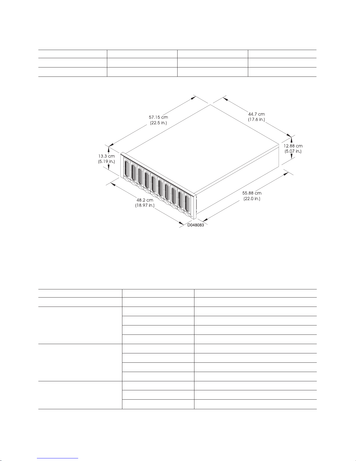
Table 9. Drive Module Dimensions Table (continued)
Criteria Height Width Depth
No Front Panel 12.9 cm (5.1 in.) 44.7 cm (17.6 in.) 55.9 cm (22.0 in.)
Packaged for Shipping 38.1 cm (15.0 in.) 61.4 cm (24.0 in.) 83.2 cm (32.7 in.)
Figure 2. Dimensions of Drive Module
Heating and Air Conditioning
Table 10 lists the temperature, humidity, and air flow requirements for the controller
and drive modules.
Table 10. Environmental Requirements
Element Unit of Measure Requirement
Air Flow Air flows from front to back
Altitude Below Sea LevelAbove Sea Level
Operating Range 30.5 m (100 ft.)3,000 m (9,840 ft.)
Storage Range 30.5 m (100 ft.)3,000 m (9,840 ft.)
Transit Range 30.5 m (100 ft.)12,000 m (40,000 ft.)
Temperature Optimum¹ 22° C (72° F)
Operating Range¹ 10° C to 40° C (50° F to 104° F)
Storage Range -10° C to 50° C (14° F to 122° F)
Transit Range -40° C to 60° C (-40° F to 140° F)
Temperature Change (maximum
allowed)
Operating Range 10° C (18° F) per hour
Storage Range 15° C (27° F) per hour
Transit Range 20° C (36° F) per hour
38 IBM 2102 Model F10 and Model D00 Service Guide
Page 69

Table 10. Environmental Requirements (continued)
Element Unit of Measure Requirement
Relative Humidity (no
condensation)
¹ If you plan to operate the controller module at altitudes between 1000 m and 3000 m (3280 ft. and 9850 ft.), you
must lower the environmental temperature 1.7° C (3.3° F) for every 1000 m (3280 ft.) above sea level.
Operating Range 20% to 80%
Storage Range 10% to 90%
Transit Range 5% to 95%
Maximum Dew Point 26° C (79° F)
Maximum Humidity Gradient 10% per hour
Electrical
Table 11 and Table 12 list the electrical power requirements for the controller and
drive modules.
Table 11. Controller Module Power Requirements
Item Unit of Measure Requirement
Circuit Breaker 3.0 A (slow-blow fuse per power supply)
Controller Module AC
Power
¹ Typical current at 240 v AC, 60 Hz (assumes 0.70 power efficiency, 0.99 power factor).
Nominal Voltage 90 to 264 v AC
Frequency 50/60 Hz
Idle Current 1.0¹
Maximum Operating Current 1.0¹
Maximum Surge Current 2.0¹
Table 12. Drive Module Power Requirements
Item Unit of Measure Requirements
USA and Canada International
AC Power Nominal Voltage 100 v AC 240 v AC
Frequency 50/60 Hz 50/60 Hz
Idle Current 3.5 A¹ 1.75 A²
Max. Operating Current 4.5 A¹ 2.25 A²
Max Surge Current 5.0 A¹ 2.52 A²
Circuit Breaker 3.0 A per unit³
¹ Typical current at 120 v AC, 60 Hz (assumes 0.72 power efficiency, 0.99 power factor).
² Typical current at 240 v AC, 60 Hz (assumes 0.72 power efficiency, 0.99 power factor).
³ Recommend a dedicated line with no more than four 120 v AC units per 20 amp circuit.
Site Wiring and Power Considerations
The controller module is a nominal 90 v AC to 264 v AC, 50/60 Hz unit that meets
standard voltage requirements for both domestic (USA) and international (outside
USA) operation. It uses standard industrial wiring with a line-to-neutral or line-to-line
power connection (Table 13 on page 40).
Consider the following when preparing the site and cabinet for installation:
Chapter 2. Installation And Removal Guide 39
Page 70

v AC power source. The AC power source must provide the correct voltage,
current, and frequency specified on the manufacturer’s nameplate. Internal AC
distribution boxes (such as the cabinet’s power units) must be able to handle the
power requirements for this unit (Table 11 on page 39). You must have an
independent AC power source for each power supply in the controller module in
order to maintain redundancy.
v Earth ground. There must be an earth ground conductor on the AC power
source.
v Circuit overloading. Make sure the power circuits and associated circuit
breakers in both the cabinet and building provide sufficient power and overload
protection. To prevent possible damage to the unit, isolate its power source from
large switching loads (such as air conditioning motors).
v Power interruptions. The controller module will withstand the following applied
voltage interruptions:
– Input transient: 50% of nominal voltage
– Duration: one half cycle for the controller module; one full cycle for the drive
module
– Minimum frequency: once every 10 seconds
v Power failures — Once power is restored after a complete power failure, the
unit will automatically perform a power-up recovery sequence without operator
intervention.
Table 13. Site Wiring Voltages
Input Power Connection 50 Hz 60 HZ
Nominal Minimum Maximum Nominal Minimum Maximum
Single-Phase Line to
Neutral
Single-Phase Line to
Line
100 90 107 100 90 107
127 114 136 120 104 127
220 198 235
230 207 246
240 216 264
200 180 214 200 180 214
208 180 220
240 208 264
Power Cord Routing Notes
The controller and drive module each use two AC power cords (one for each power
supply).
The rackmount cabinet may have one or two AC Power Distribution Units (PDUs).
Each PDU has its own power cord. Ideally, the redundant power supplies on the
controller and device modules will each be connected to a separate PDU to provide
AC power source redundancy. However, if the rack contains only a single PDU,
then all power supplies will have to be connected to a single AC power source.
Additionally, if there are not enough PDU outlets for every power supply of all rack
components, then it will be necessary to use a Y power cable to connect two power
supplies to the same PDU outlet.
The power cabling priority should be:
40 IBM 2102 Model F10 and Model D00 Service Guide
Page 71
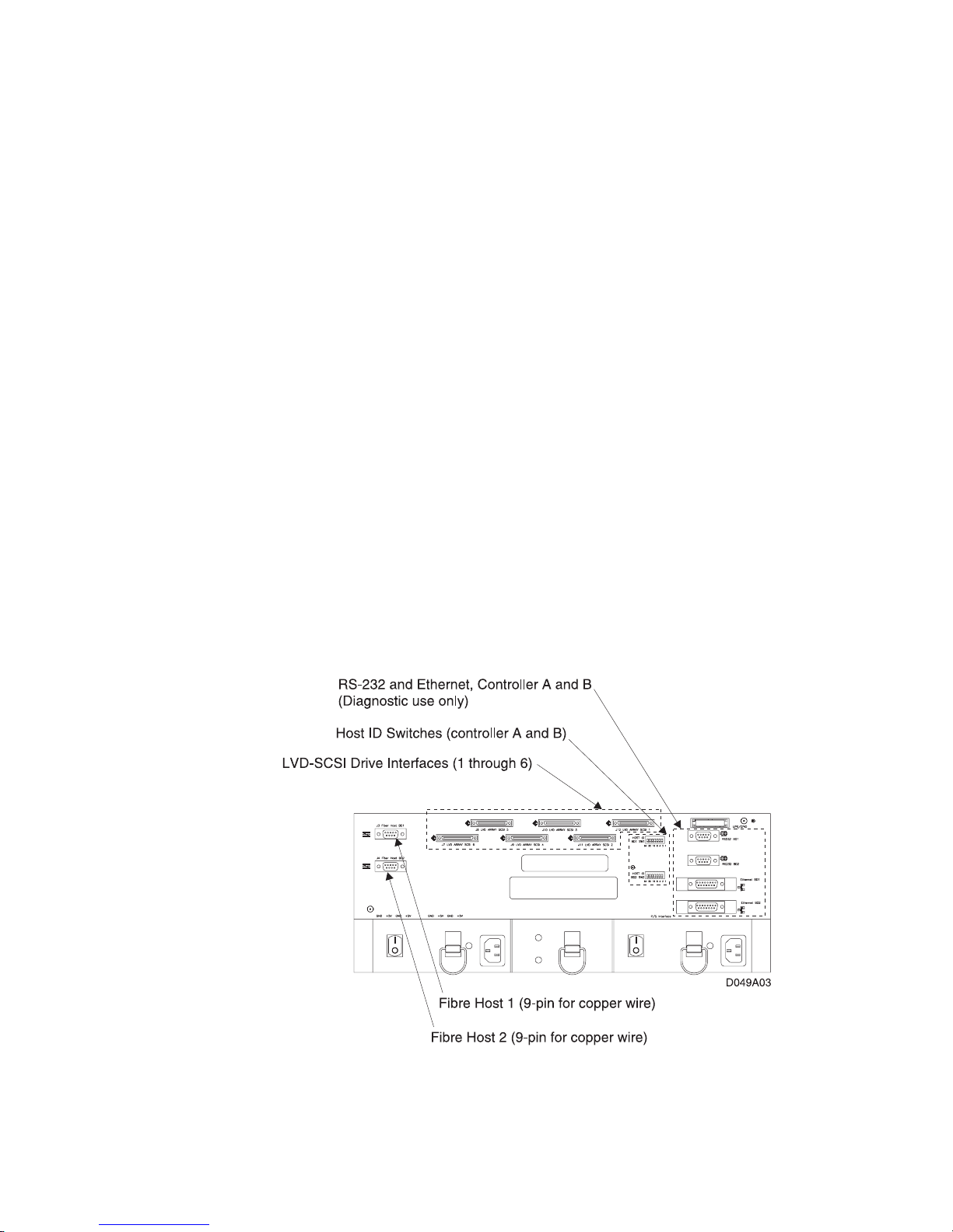
1. There is at least 1 PDU outlet available for each module (controller, drive or
hub) in the rack. This is the minimum requirement.
2. If there is only a single PDU in the rack, but an outlet is available, then each
controller module power supply should be connected to a different PDU outlet.
3. If there is only a single PDU in the rack and each controller module power
supply is connected to a separate PDU outlet and there are still outlets
available, then each device module power supply should be connected to a
separate PDU outlet until no more outlets are available.
4. If there are 2 PDUs in the rack, then each controller module power supply
should be connected to a different PDU.
5. If there are 2 PDUs in the rack and each controller module power supply is
connected to a different PDU and there are still outlets available, then each
device module power supply should be connected to a different PDU until there
are no more outlets available.
Interface Connectors and Cables
The controller module supports the following interface protocols:
v Host interface – Fibre Channel (copper wire or fiber optic), one per controller
v Drive interface – LVD-SCSI (low-voltage differential, small computer system
interface), six drive channels
v Diagnostic interface – Ethernet or RS-232 (serial), one each per controller
Connectors and Host IDs
The host ID switches and connectors for interface cables are on the
(Figure 3), located on the back of the controller module.
connector plate
Figure 3. Interface Connections on Controller Module
Chapter 2. Installation And Removal Guide 41
Page 72

Host and Drive ID Numbers
Each controller on a Fibre Channel loop must have a unique
Fibre Host ID number
The host ID numbers assigned to each controller are based on two elements:
v Host ID numbers set through hardware switches on the controller module (see
Figure 3 on page 41). There are seven Host ID switches that allow you to set ID
numbers 0 through 127 for each controller. The factory default settings are ID #5
for Controller A and ID #4 for controller B (see “Configuring the Controller
Module” on page 54).
v Software algorithms that calculate the actual Fibre Channel address, based on
the controller module’s hardware settings and position on the loop or hub.
There are also
drive SCSI ID numbers
that identify each controller to the LVD-SCSI
drives. Drive ID numbers are assigned to each controller at the factory and cannot
be changed. However, SCSI drive IDs on drive modules can be changed manually.
Refer to Step 5 on page 51 under ″Installing the Drive Module″ for details on setting
the drive SCSI IDs.
Fibre Channel Host Cable Requirements
Table 14 lists the cable requirements for all Fibre Channel connections. For fiber
optic connections, you must use multi-mode, 50 micrometer fiber optic cable and a
Media Interface Adapter (MIA) shown in Figure 4.
Table 14. Fibre Channel Interface Cable Requirements
Cable Descriptions Order Information
Item Media Type Data Size Transfer Speed Range FRU Part No. Length
Fiber optic
(multi-mode, 50
micrometer)
Shortwave
laser
100 MB/sec 1062.5 Mbaud Up to 0.5
kilometer
03K9202 5 meter
03K9204 25 meter
.
Figure 4. Media Interface Adapter (MIA)
LVD-SCSI Drive Cable Requirements
To connect the controller module to a drive module, you must use 68-pin, VHDCI
(very high density cable interface) LVD, Ultra SCSI-2 cables. The maximum length
for any SCSI cable is 25 m (82 ft.). Refer to “SCSI Cables” on page 194 for SCSI
cable information. The controller module has six drive SCSI connectors that support
both 8-bit and16-bit interface protocol. Each connector represents a single drive
channel that supports up to 10 drives per channel for a total of 60 drives. Refer to
“LVD-SCSI Drive Cable Routing Examples” on page 59 for examples of connecting
the controller module to one or more LVD-SCSI drive modules. Table 15 on page 43
lists the SCSI cable that you can use on this drive module.
42 IBM 2102 Model F10 and Model D00 Service Guide
Page 73
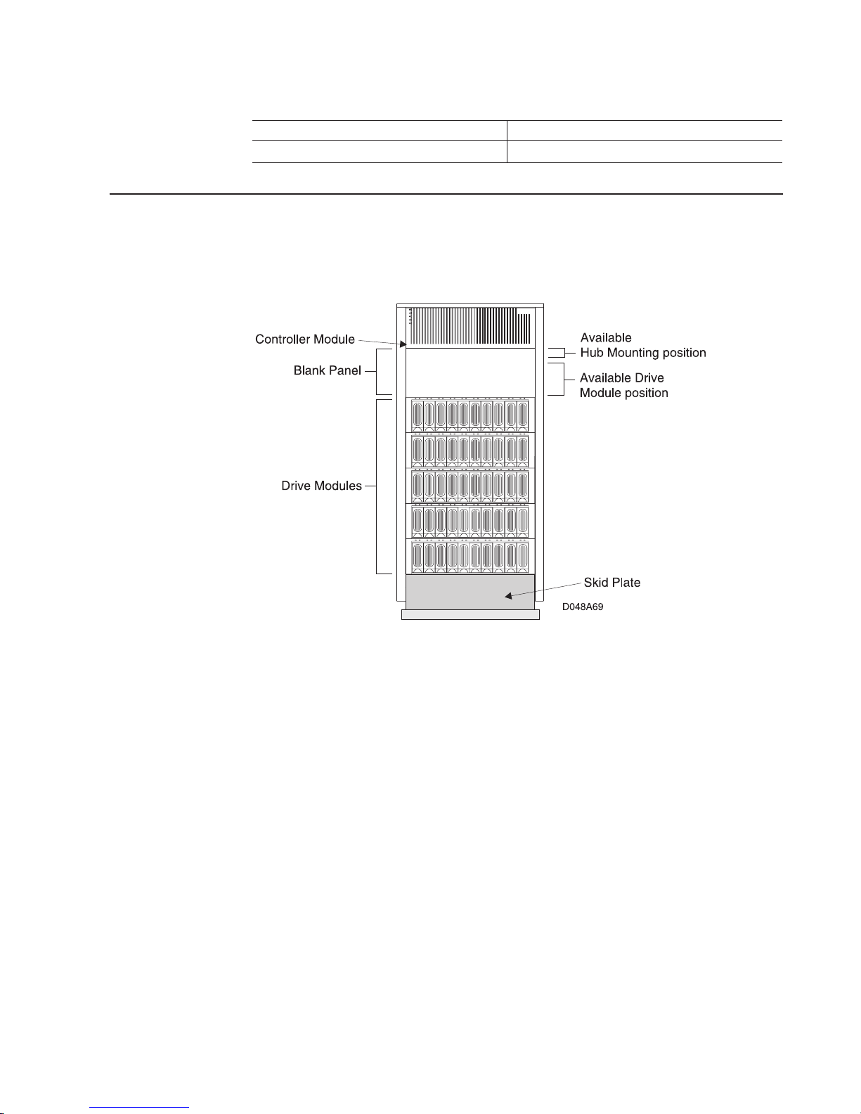
Table 15. Drive Module SCSI Interface Cable
Cable Part Number Length
O3K9195 2.0 meter
Preparing the Rackmount Cabinet
To prepare the rackmount cabinet for installation (Figure 5), review the appropriate
checklist and complete all applicable preparatory procedures.
Figure 5. Rackmount Cabinet
Cabinet Preparation Task List
If you are installing a new IBM 2101-100 Seascape Solutions rack with the rack
components (controller module, drive modules and optional hubs) already installed,
then use the following preparation checklist:
1. Move the rack to its final destination.
2. Unpack and set up the rack using the installation procedures in the
Solution Rack, Installation and Service Guide, IBM 2101 Model 100
SY27-7606.
Important: The rack must be able to support the weight of all devices that will
be installed, without tipping over. The rack may need to be secured
using a stabilizer plate, by being bolted to the floor, or by some
other method specific to the rack being used and the installation
site. Refer to the rack documentation for more information.
3. If applicable, install the optional remote support switch and modem using the
procedures in “Remote Support Attachment of the WTI Data Switch and
Modem” on page 229.
4. Go to “Configuring the Controller Module” on page 54.
Seascape
,
Chapter 2. Installation And Removal Guide 43
Page 74

If you are installing a new controller module and any other rack components into an
existing 19 inch compatible rack, then use the following preparation checklist:
1. Move the rack to its final destination.
2. Unpack and set up the rack using the installation procedures from the
appropriate rack document.
3. Remove external rack panels, if applicable.
4. Stop all I/O activity to the existing devices in the rack, if applicable.
5. Turn off power to all devices in the rack and turn off the rack power.
6. Install the support rails for mounting the controller module and any drive
modules in the rack if they are not already installed. See “Installing the Support
Rails”.
7. Install the controller module in the rack. See “Installing the Controller Module”
on page 45.
8. Install the drive modules in the rack. See “Installing the Drive Module” on
page 49.
9. If applicable, install any rackmount hubs in the rack using the installation
procedures in
Guide, IBM 2103 Model H07
10. If applicable, install the optional remote support switch and modem using the
procedures in “Remote Support Attachment of the WTI Data Switch and
Modem” on page 229.
Fibre Channel Storage Hub, Installation, Service, and User’s
, SC26-7289.
11. Go to “Configuring the Controller Module” on page 54.
Installing the Support Rails
About Support Rails
To install the controller module or drive modules in a rackmount cabinet, you need
the appropriate rackmount support rail kit.
Where you place the support rails in the cabinet depends on where you intend to
position the controller or device modules in the cabinet. In a standard configuration,
the controller module is installed at the top of the rack and device modules are
installed beginning at the bottom of the rack and moving upwards. If you are using
a different type of mounting system, refer to the documentation shipped with your
cabinet hardware.
Note: If your cabinet already has a set of support rails installed at the position
where you are installing the controller or drive modules, you may skip to the
next task.
Instructions
Use this procedure only if you need to install mounting hardware in a cabinet before
installing a controller or drive module. These instructions assume that you are
following the cabinet preparations task list in “Cabinet Preparation Task List” on
page 43. Make sure that you have a minimum of two feet around the outside of the
cabinet in order to install the support rails and complete the remaining installation
procedures.
44 IBM 2102 Model F10 and Model D00 Service Guide
Page 75

1. Turn off the power, if applicable.
Stop all I/O activity to the devices in the cabinet in which you are installing the
controller module. Turn off the power switches on both AC distribution boxes in
the cabinet.
2. Install the support rails.
If instructions were shipped with the support rail kit, then follow those
instructions for installing the support rails. If you are installing more than one
rack module, you must install support rails for each unit.
a. Loosen the adjustment screws on both side rails and adjust them to fit the
rack.
b. Use the front alignment pins to line up the front of the rails with the rack
mounting holes. The alignment pins are designed to allow installation into a
variety of racks, so you may have to remove the alignment pins that do not
align correctly with the holes in the rack you are using.
c. Secure the side rails to the rack cabinet with the mounting hardware.
v Use eight screws with nuts for the controller rails (two in the front and two
in the back of each rail).
v Use six screws with nuts for the drive drawer rails. Use only one screw in
the front lower mounting hole for now – the second screw will be used
when the drive drawer is installed.
Make sure that both side rails are parallel and level with one another in
the rack cabinet.
v Tighten the rail adjustment screws.
3. Go to the next task.
End of Procedure
Installing the Controller Module
Tools and Equipment
Antistatic wrist strap, screwdrivers, Host Fibre interface cables and MIA, Drive
LVD-SCSI cables, optional Secondary interface cables (RS-232 or Ethernet), tie
wraps and a cart or level surface (to hold the FRUs).
Instructions
Use this procedure to install a controller module on the support rails in a rackmount
cabinet. These instructions assume that you are following the cabinet preparations
task list in “Cabinet Preparation Task List” on page 43.
1. Check the contents of the shipping container.
The controller module shipment should include:
v Power cords. These attach the controller module to the AC power sources
inside the cabinet.
v Other items. Depending on how you ordered the controller module, other
items may be included, such as storage management software (CD or
diskettes), interface cables, 16-bit terminators, mounting hardware, or
additional documentation. Refer to the shipping list or invoice included with
the controller module for a complete list of items.
Chapter 2. Installation And Removal Guide 45
Page 76

2. Remove the front cover from the controller module (Figure 6).
Attention: Electrostatic discharge can damage sensitive components. Use a
grounding wrist strap or other antistatic precautions before removing or
handling any components in the cabinet.
Figure 6. Removable Covers on the Controller Module
3. Remove all the FRUs, using Figure 7, Figure 8 on page 47 and Figure 9 on
page 47 as a guide.
Figure 7. Removing The FRUs
46 IBM 2102 Model F10 and Model D00 Service Guide
Page 77
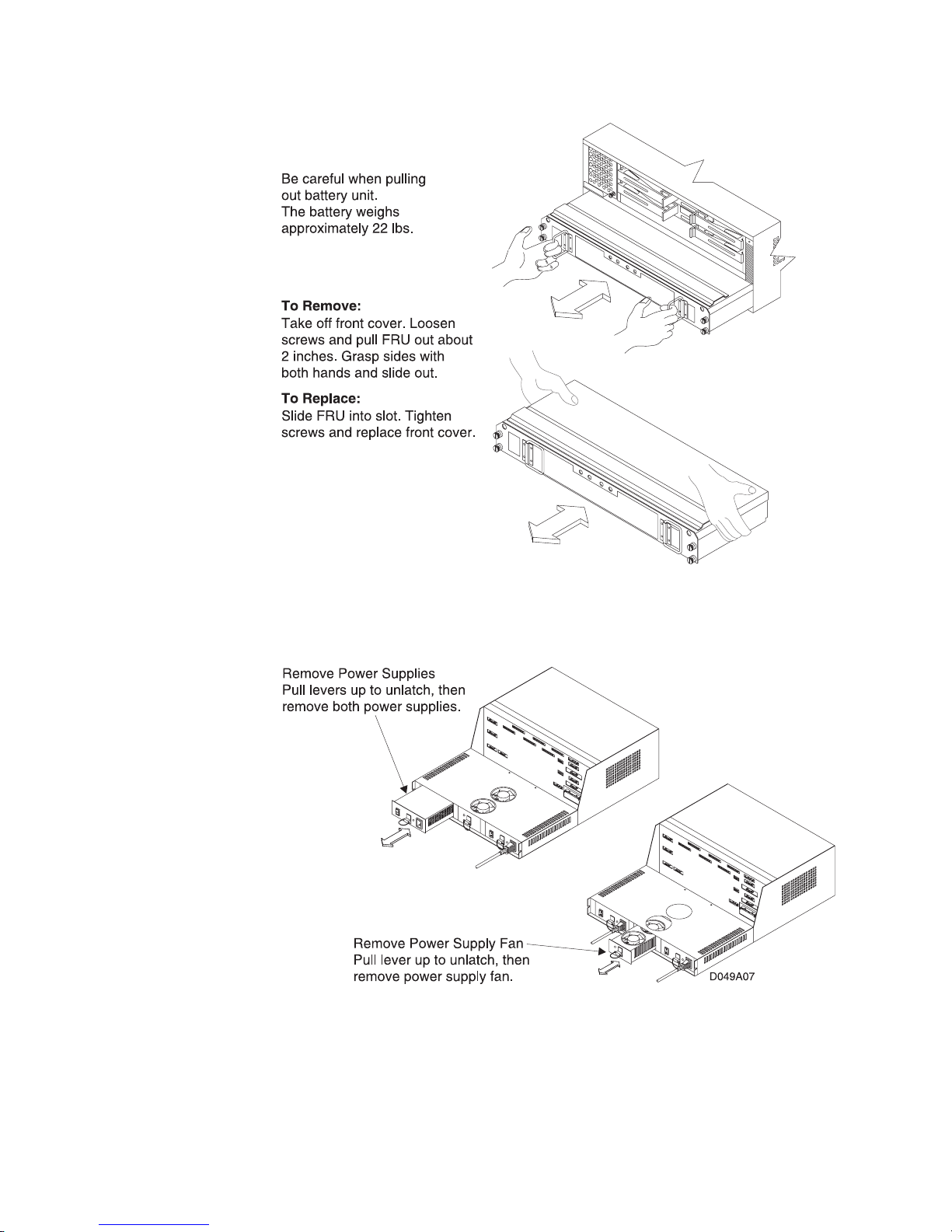
Figure 8. Removing The FRUs – cont.
Figure 9. Removing The FRUs – cont.
4. Put the controller module in the cabinet (Figure 10 on page 48).
At front of the cabinet, set the controller module on the support rails and slide
it to the back of the cabinet.
5. Secure the controller module (Figure 10 on page 48).
Chapter 2. Installation And Removal Guide 47
Page 78
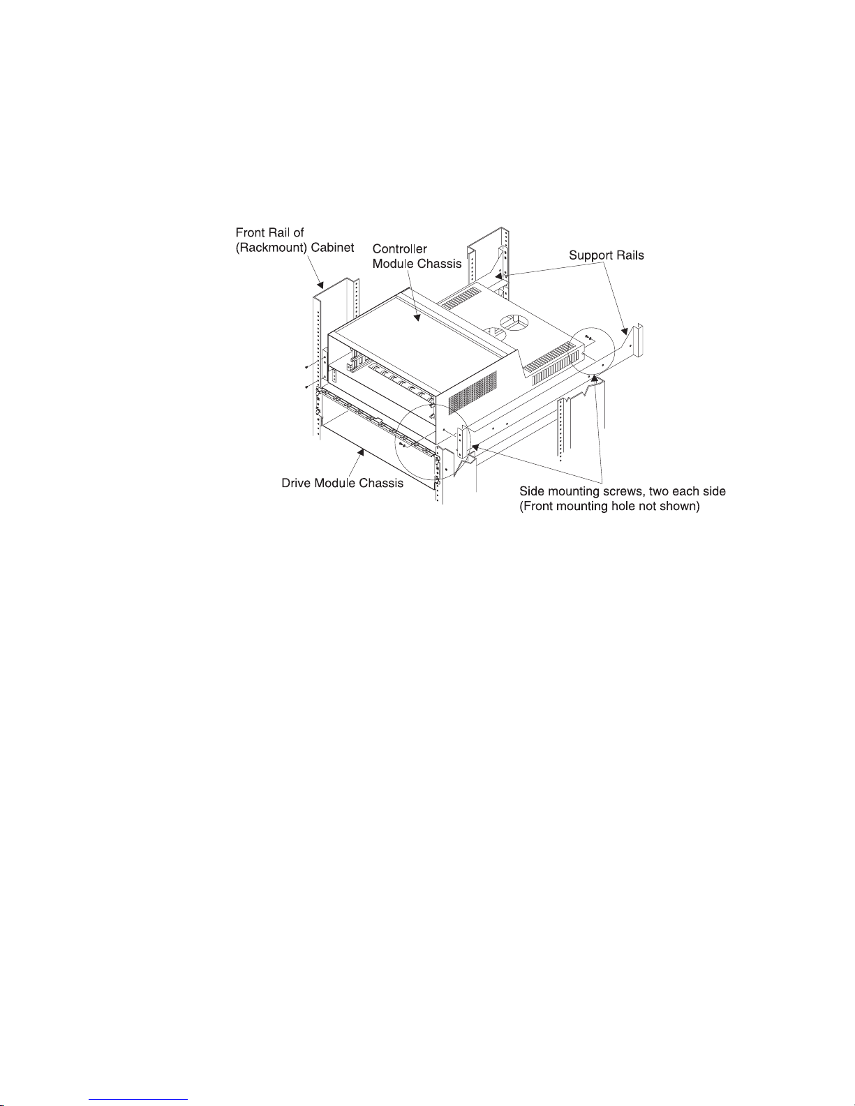
Align the controller module chassis holes with the mounting holes on the side
of each rail. Insert a self-tapping screw into the mounting holes on the side of
each rail and tighten. Use only the holes designated in Figure 10 to mount the
controller module. Attention:
components.
Use a grounding wrist strap or other antistatic precautions
Electrostatic charge can damage sensitive
before handling any components in the cabinet.
Figure 10. Chassis Mounting on Support Rails
6. Replace all FRUs that you removed in Step 3 on page 46.
Reverse the instructions shown in Figure 7 on page 46, Figure 8 on page 47
and Figure 9 on page 47 to install the controllers, controller fan, battery, power
supplies, and power supply fan into the chassis. As you install the FRUs, make
sure that you lock all FRUs securely in place.
Note: The power supplies are interchangeable, so you can insert them in
either slot.
7. Connect the LVD- SCSI drive cables (Figure 11 on page 49).
Attach LVD-SCSI drive cables to the drive LVD connectors on the controller
module.
48 IBM 2102 Model F10 and Model D00 Service Guide
Page 79
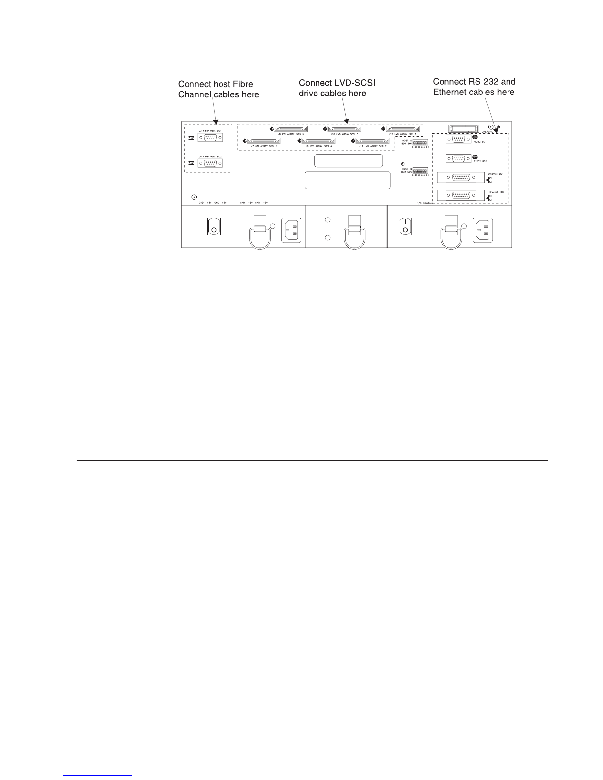
Figure 11. Interface Connections on a Rackmount Controller Module
8. If applicable, attach secondary interface cables (Figure 11).
There is one RS-232 and one Ethernet connector for each controller. Attach
cables to these connections if you need to perform troubleshooting, special
configuration tasks or you are connecting the controller to a network RAID
storage Management PC.
9. Route and secure the Fibre Channel interface cables. If all the drive modules
are already installed and connected, then also route and secure the SCSI
interface cables.
Arrange the interface cables so they clear the vents on the back of the
controller module. Secure the cables with tie-wraps.
10. Go to the next task.
End of Procedure
Installing the Drive Module
Tools and Equipment
v Antistatic wrist strap or other antistatic protection device
v screwdrivers
v all drive module FRUs
v Table or counter-top to hold FRUs
Instructions
Use this procedure to install a drive module on the support rails in a rackmount
cabinet. These instructions assume that you are following the “Cabinet Preparation
Task List” on page 43.
Attention: Electrostatic discharge can damage sensitive components. Use a
grounding wrist strap or other antistatic precautions before removing or handling
any components in the cabinet.
1. To reduce weight, remove the drive FRUs from the drive module, using
Figure 12 on page 50 and Figure 13 on page 51 as a guide.
Chapter 2. Installation And Removal Guide 49
Page 80

Be sure to keep track of which drive you remove from which location. You must
replace the drives in the exact slots from which you removed them.
Figure 12. Removing the Drive Module FRUs
50 IBM 2102 Model F10 and Model D00 Service Guide
Page 81

Figure 13. Removing the Drive Module FRUs – cont.
2. Put the Drive Module in the cabinet.
At the front of the cabinet, set the Drive Module on the support rails and slide it
to the back of the cabinet.
3. Secure the Drive Module.
Align the front holes on each side of the chassis with the holes on the front of
the support rails. Secure the front of the chassis to the cabinet rails by inserting
screws through the bezel and into the holes on each side. Secure the back of
the Drive Module to the support rails with two screws, one on each side (See
Figure 92 and Figure 93 on page 177). Attention: Electrostatic discharge can
damage sensitive components. Use a grounding wrist strap or other antistatic
precautions before handling the FRUs.
4. Replace all of the FRUs that you removed in Step 1 on page 49.
Reinstall the drives, fans, power supplies, and ESM board FRU into the chassis
in reverse order that you removed them in Step 1 on page 49. Make sure that
you install the drives in their correct slots, and lock all FRUs securely into place.
Note: The power supplies and fans are interchangeable, so you can insert
them in either slot as long as you:
v Make sure that the lever opens in the correct direction. The power
supplies have reversible left and right levers. The lever on the left
power supply opens to the right; the lever on the right power supply
opens to the left.
v Make sure that the fans are in the correct orientation before you
attempt to install them (see Figure 12 on page 50).
5. Set the Drive Module Interface Options.
Chapter 2. Installation And Removal Guide 51
Page 82

There is a Tray ID switch and a set of Option switches on the back of the
Drive Module that are used to select interface options, and to determine
whether these drives are configured as two 5-drive buses or one 10-drive bus
(see Figure 14 on page 53). These switches should be set as follows:
v Tray ID:
This switch is used to identify the drive module based on its location in the
rack. The rack will support up to six drive modules and the tray ID must be
unique for each. Drive Modules should be installed beginning at the bottom of
the rack, moving upward with each succeeding Drive Module installation.
Set the Tray ID of the first (bottom most) Drive Module to ″1″, set the second
Drive Module Tray ID to ″2″, and so on, proceeding to the sixth Drive Module
(Tray ID=″6″), installed immediately below the Controller Module. This is a
fully populated rack.
v Option Switches:
These switches are used to set the interface options and set the SCSI IDs of
the drives in the Drive Module. Unless instructed otherwise, you should only
have to change Switch 1, the Bridge Disable bit. All other option switches
should be in the ″OFF″ position (see “Factory Settings” on page 191 for more
detail about Option Switches).
When the Bridge Disable switch (Switch 1) is in the ″ON″ position, the Drive
Module acts as two independent 5–drive buses with one SCSI connection to
each bus. When this switch is ″OFF″, the Drive Module acts as one 10–drive
bus with two SCSI connections (see “Drive Numbering” on page 144).
The setting of this switch is determined by the number of drive modules
installed in the rack:
a. 1, 2 or 3 drive modules installed: The Bridge Disable bit (switch 1)
should be in the ″ON″ position for all drive module and each module
should have two SCSI connections to the controller module.
b. 4 drive modules installed: The Bridge Disable bit (switch 1) should be in
the ″ON″ position for drive modules 2 and 3 (the second and third drive
modules from the bottom of the rack), and ″OFF″ for drive modules 1 and
4. Drive modules 2 and 3 will each have two SCSI connections to the
controller module, and drive modules 1 and 4 will each have a single
SCSI connection to the controller module.
c. 5 drive modules installed: The Bridge Disable bit (switch 1) should be in
the ″ON″ position for drive module 3 (the third drive modules from the
bottom of the rack), and ″OFF″ for drive modules 1, 2, 4 and 5. Drive
module 3 will have two SCSI connections to the controller module, and all
the rest will have a single SCSI connection to the controller module.
d. 6 drive modules installed: The Bridge Disable bit (switch 1) should be in
the ″OFF″ position for all drive module and each module will have single
SCSI connections to the controller module.
See “LVD-SCSI Drive Cable Routing Examples” on page 59 for examples.
52 IBM 2102 Model F10 and Model D00 Service Guide
Page 83

Figure 14. Tray ID and Option Switches
6. Connect the Cables
There are two SCSI interface connectors on the ESM board (Figure 15 on
page 54) for attaching the SCSI cables from the controllers to the Drive Module
SCSI buses. Depending on the setting of the Bridge Disable switch (Option
Switch 1), you will have to connect either one or two SCSI cables between the
controller and drive modules:
v If the Bridge Disable switch is in ″ON″ position: Connect two cables, one
to each connector on the ESM board.
v If the Bridge Disable switch is in ″OFF″ position: Connect one SCSI cable
to the Bus 1 one connector (left connector when viewed from the back) on
the ESM board.
Attach the SCSI interface cables from the controller module to the SCSI
connectors on the ESM board.
7. Route and secure the SCSI interface cables.
Arrange the interface cables so that they clear the vents on the back of the
module. Secure the cables with tie-wraps.
8. Connect the power cords (Figure 15 on page 54).
Read “Power Cord Routing Notes” on page 40. Make sure both power switches
are turned off and connect both power cords to the drive module.
Chapter 2. Installation And Removal Guide 53
Page 84
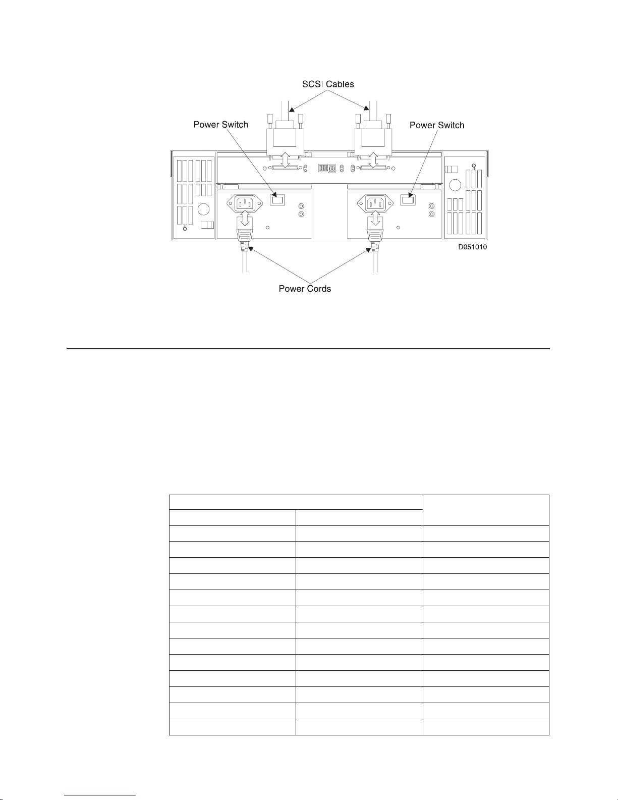
Figure 15. Connecting Interface Cables and Power Cords
9. Go to the next task.
Configuring the Controller Module
1. Set the Fibre Host IDs (Figure 16 on page 55).
Each controller on a Fibre Channel loop must have a unique
number
switches are located on the back of the controller module (upper right corner).
The Host ID settings determine the SCSI ID of the individual controllers on the
Fibre channel loop as described in the table below. If you need to change the
controller’s host ID setting, move the switches up or down.
As there are 127 valid switch settings, it is recommended that each controller
have a unique address selected from the following table:
(refer to “Host and Drive ID Numbers” on page 42). The Fibre Host ID
Fibre Host ID
54 IBM 2102 Model F10 and Model D00 Service Guide
Host ID Setting
Hex Binary (switch setting)
04 0000100 E1
05 0000101 E0
06 0000110 DC
07 0000111 DA
08 0001000 D9
09 0001001 D6
0A 0001010 D5
0B 0001011 D4
0C 0001100 D3
0D 0001101 D2
0E 0001110 D1
0F 0001111 CE
10 0010000 CD
Controller SCSI ID
Page 85
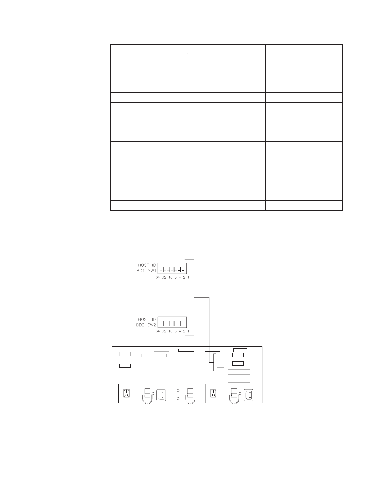
Host ID Setting
Hex Binary (switch setting)
11 0010001 CC
12 0010010 CB
13 0010011 CA
14 0010100 C9
15 0010101 C7
16 0010110 C6
17 0010111 C5
18 0011000 C3
19 0011001 BC
1A 0011010 BA
1B 0011011 B9
1C 0011100 B6
1D 0011101 B5
1E 0011110 B4
1F 0011111 B3
Controller SCSI ID
On subsystems connected to AIX hosts, the controller SCSI ID is used to
identify the controllers (DACs) in the subsystem when configuring the
subsystem or reporting errors. You can use this table to map the reported SCSI
ID to an individual controller based on its Host ID setting.
Figure 16. Setting the Fibre Host IDs
2.
Verify that the Media Interface adapters are securely attached to the fibre
channel connectors (J3 and J4) on the back of the controller module (Figure 11
on page 49
Chapter 2. Installation And Removal Guide 55
Page 86

on page 49). Attention: Bending or damaging Fibre Channel cables could
result in degraded performance or data loss. Do not pinch the cables with tie
wraps. Do not make sharp bends when routing the cables. Do not step on the
cables or locate them in aisles or walkways.
3. Attach the host Fibre Channel cables (Figure 11 on page 49).
Attach the Fibre Channel cable from host adapter 1 to connector J3 (Fiber Host
BD 1) on the back of the controller module. Attach the FC cable from host
adapter 2 to connector J4 (Fiber Host BD 2).
Completing the Installation
Start-up Notes
v Adding a new 2102 RAID subsystem to an existing storage environment is
non concurrent. If you are adding this 2102 RAID storage subsystem to an
existing installation (for example, you are connecting a second 2102 subsystem
to an existing host), you must stop all activity from the existing host(s) and reboot
them in order to add the new subsystem.
v You must power up the drive modules before powering up the controller
module. Controller modules will not acknowledge any attached drives that are
initially powered up after the controller module.
v The controller and drive modules have
the status of both the overall modules and the individual components within the
unit. Check all LEDs on the controller and drive modules (front and back) when
you power up the unit to make sure there are no problems.
light emitting diodes
(LEDs) that indicate
Configuration Notes
Once the controller module hardware is installed and turned on, you may need to
perform certain tasks to complete the installation. These tasks may include:
v Verifying the installation
v Updating controller firmware
v Updating drive firmware
Starting Up the Subsystem
Tools and Equipment
Power cords (2) shipped with controller module
Instructions
Use these instructions to connect the controller module power cords, turn on the
power, and check the subsystem status.
1. Read “Power Cord Routing Notes” on page 40. Go to Step 2.
2. Make sure that both power switches on the controller module are turned off
(Figure 17 on page 57).
3. Plug both power cords into the controller module (Figure 17 on page 57).
4. Plug power cords into the AC outlets.
56 IBM 2102 Model F10 and Model D00 Service Guide
Page 87

If possible, plug each controller power cord into an independent power source to
maintain power redundancy (see “Power Cord Routing Notes” on page 40).
Figure 17. Controller Module Power Cords and Power Switches
Figure 18. Drive Module Power Switches
5. Turn on the power as follows:
a. Rack: The rack power is active when each Power Distribution Unit (PDU)
b. Hub (if applicable): Hub power is active when the hub power cord is
c. Drive Modules: Turn on both power switches on the back of each drive
d. Controller Module: Turn on both power switches on the back of the
power cord is plugged into the external power source. A green light on the
PDU indicates that power is active to that PDU.
plugged into the rack or external power source.
module (see Figure 18). During the power-up process, the Drive Module
LEDs may turn on and off intermittently. When power-up is complete, the
green power LEDs will be on and all amber LEDs should be off.
Controller Module (see Figure 17). The controller module may take from
three to ten seconds to power-up. During this time, the Controller Module
LEDs may turn on and off intermittently.
Chapter 2. Installation And Removal Guide 57
Page 88

Once the Controller Module has powered up, the controllers will spin up the
drives in the drive modules. Depending on the number of drives in the
subsystem, this process could take several minutes to complete.
e. Host: Have the customer power up or reboot the host system, to allow
recognition of the array.
6. Check the controller and drive modules for faults.
Go to “Using the Status LEDs” on page 75 and follow the instructions for check
the controller module’s status. If any Fault LEDs turn on and remain on, refer to
the appropriate page listed in Table 16 on page 76 and Table 17 on page 78.
Go to “Check the Overall Hardware Status” on page 156 and follow the
instructions for checking the drive modules’ status. If any fault LEDs come on
and remain on, refer to the appropriate Service Page listed in Table 33 on
page 157 and Table 34 on page 158.
7. Replace the controller module front cover (Figure 6 on page 46).
8. Go to “Verifying the Installation”.
End of Procedure
Verifying the Installation
Tools and Equipment
You will need access to the Fibre Channel Storage Manager host software.
Instructions
Use this procedure as a guideline for verifying the subsystem configuration.
1. Read “Configuration Notes” on page 56.
2. Verify the installation using the Fibre Channel Storage Manager host software.
Some default software parameters (such as RAID level, drive groups, and
caching) are set at the factory before shipment. If Fibre Channel Storage
Manager software is already installed on the host, use it to check the current
software configuration for both the controllers and drives and to verify that both
controller boards and all drives can be seen by the host. You may also need to
change the mode of the controllers from active/passive to active/active.
Refer to the appropriate software documentation for instructions on using the
software.
v If the subsystem is attached to a Windows NT, SUN, or HP-UX host, then
use the Configuration application to verify that both controller boards and all
drives can be seen by the host. Refer to
StorWatch Fibre Channel RAID Specialist, User’s Guide
using the software.
v If the subsystem is attached to an AIX host system, use the Disk Array
Manager to verify that both controller boards and all drives can be seen by
the host. Refer to
Fibre Channel Storage Manager, Installation and User’s
Guide for the AIX Operating System
Fibre Channel Storage Manager and
for instructions on
for instructions on using the software.
Note: The controller module, drive units, or other components in your system
3. Begin normal system operation.
58 IBM 2102 Model F10 and Model D00 Service Guide
may be identified by names that differ from those used in this book. Keep
this in mind when using the software.
Page 89

End of Procedure
Removal
If you are removing the subsystem from service, you must be sure to erase any
user data on the array. Have the customer use the Storage management software
to format all existing LUNs and then delete the configuration. If the host connection
is not available or already disconnected, you can use DOS RAID Manager (DRM)
to perform these operations. Make sure the customer understands that all data will
be lost and unrecoverable. If drive drawers are being moved to another subsystem,
you must remove the configuration information written on the drives to avoid
problems. Make sure that all the drives in the drawer being used are ″unassigned″
(not part of any drive groups or LUNs) before moving.
Important: If the ″Reset Configuration″ option is used to delete the configuration
information on the drives, be aware that this function results in the
creation of a default LUN 0. You must delete this LUN after the reset
configuration function completes.
LVD-SCSI Drive Cable Routing Examples
Use the following examples for connecting a controller module to one or more
LVD-SCSI drive modules. Rackmount cabling examples begin on “Drive Cabling
Example A”.
Note: Drive numbers are shown in decimal in the following examples. Some host
or service utilities may display these values in hexadecimal format.
Drive Cabling Example A
Drive Cabling Example A shows the cabling configuration for one drive module:
Chapter 2. Installation And Removal Guide 59
Page 90
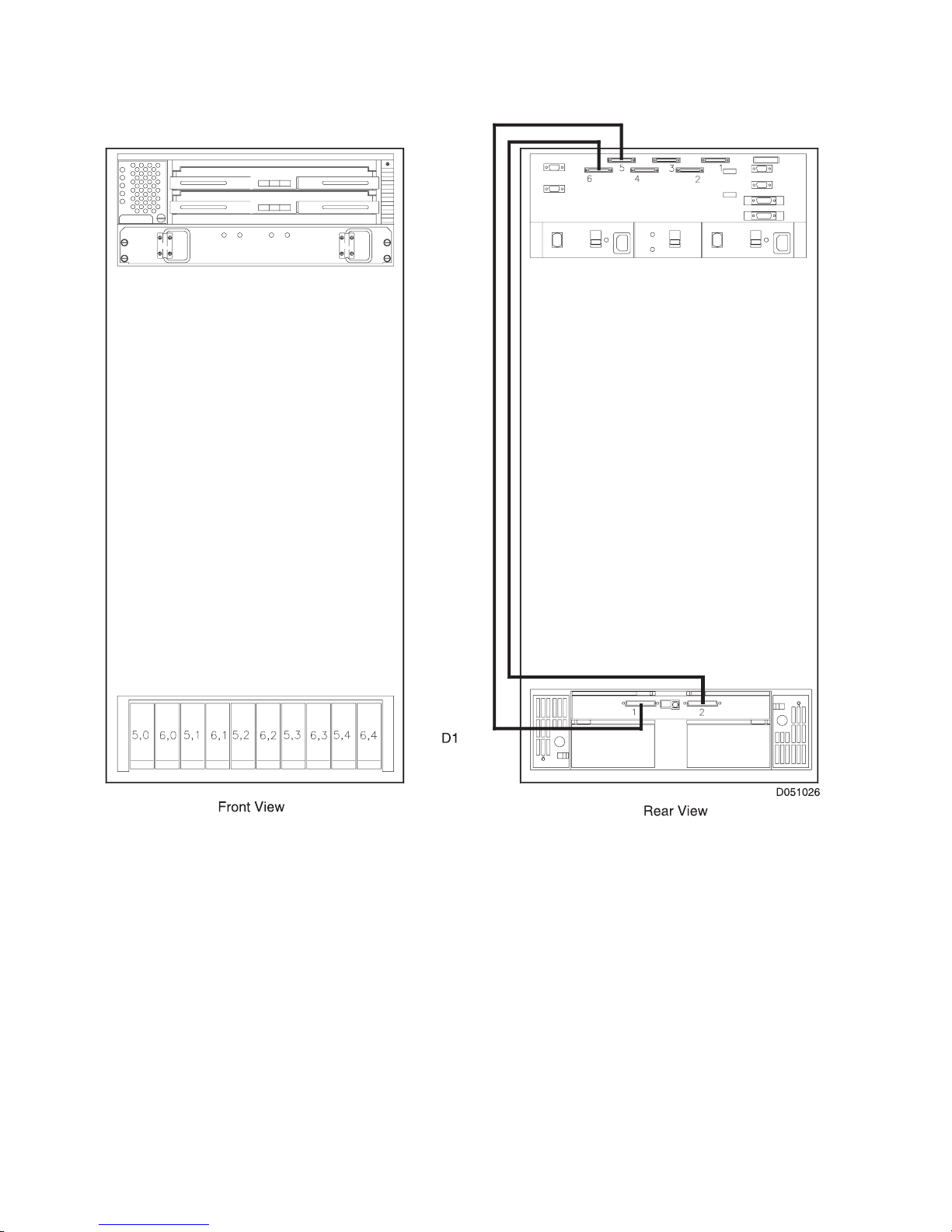
Configuration:
v One (1) Controller Module
v One (1) Drive Module
v Bridge Disable = ON
Figure 19. Rackmount Cabling to One Drive Module
Drive Cabling Example B
Drive Cabling Example B shows the cabling configuration for two drive modules:
60 IBM 2102 Model F10 and Model D00 Service Guide
Page 91

Configuration:
v One (1) Controller Module
v Two (2) Drive Modules
v All Bridge Disables = ON
Figure 20. Rackmount Cabling to Two Drive Modules
Drive Cabling Example C
Drive Cabling Example C shows the cabling configuration for three drive modules:
Chapter 2. Installation And Removal Guide 61
Page 92

Configuration:
v One (1) Controller Module
v Three (3) Drive Modules
v All Bridge Disables = ON
Figure 21. Rackmount Cabling to Three Drive Modules
Drive Cabling Example D
Drive Cabling Example D shows the cabling configuration for four drive modules:
62 IBM 2102 Model F10 and Model D00 Service Guide
Page 93
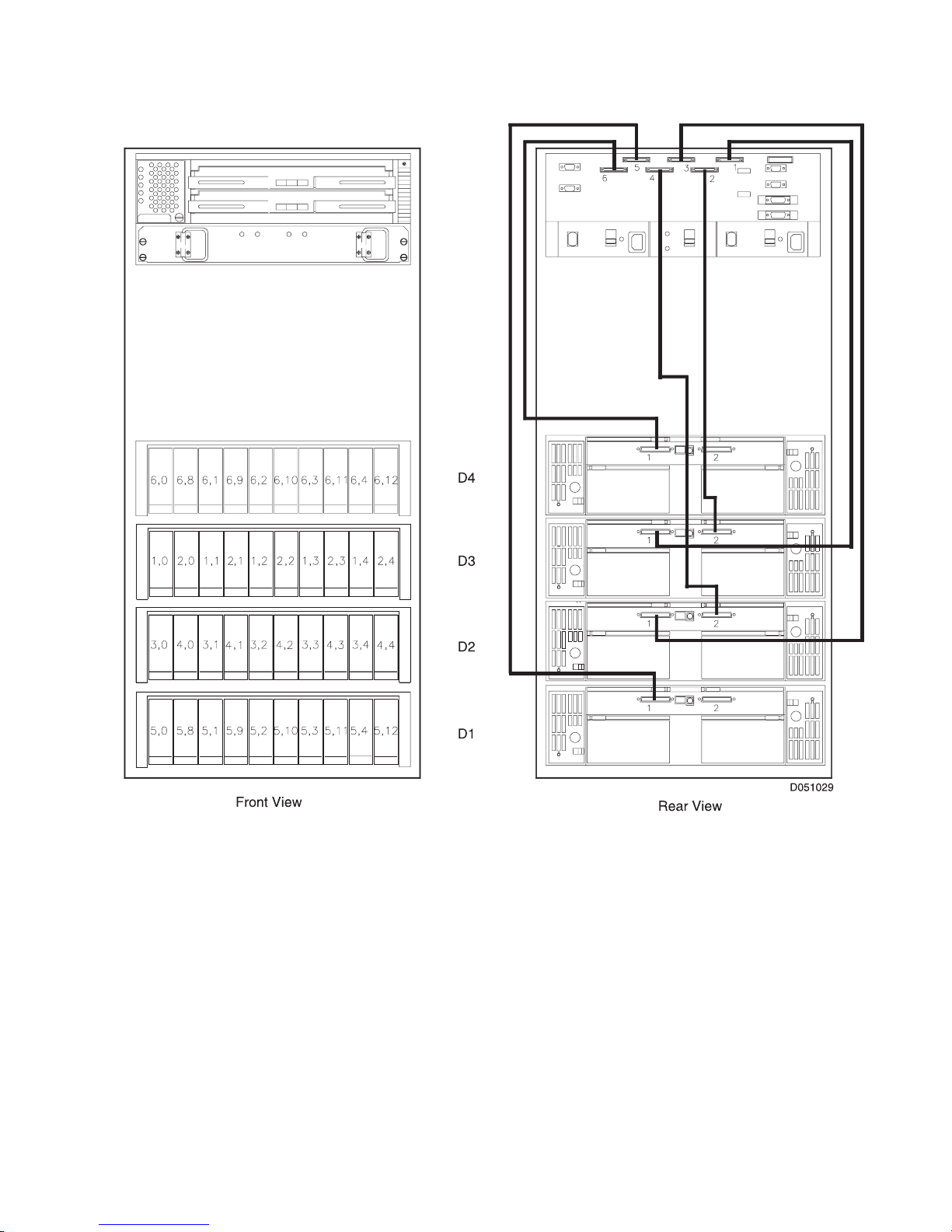
Configuration:
v One (1) Controller Module
v Four (4) Drive Modules
v Bridge Disable = OFF on Drive Modules D1 and D4
v Bridge Disable = ON on Drive Modules D2 and D3
Figure 22. Rackmount Cabling to Four Drive Modules
Drive Cabling Example E
Drive Cabling Example E shows the cabling configuration for five drive modules:
Chapter 2. Installation And Removal Guide 63
Page 94

Configuration:
v One (1) Controller Module
v Five (5) Drive Modules
v Bridge Disable = OFF on Drive Modules D1, D2, D4 and D5
v Bridge Disable = ON on Drive Module D3
Figure 23. Rackmount Cabling to Five Drive Modules
Drive Cabling Example F
Drive Cabling Example F shows the cabling configuration for six drive modules:
64 IBM 2102 Model F10 and Model D00 Service Guide
Page 95

Configuration:
v One (1) Controller Module
v Six (6) Drive Modules
v All 6 Bridge Disables = OFF
Figure 24. Rackmount Cabling to Six Drive Modules
Chapter 2. Installation And Removal Guide 65
Page 96

66 IBM 2102 Model F10 and Model D00 Service Guide
Page 97

Part 3. Controller Module Service Guide
© Copyright IBM Corp. 1999 67
Page 98

68 IBM 2102 Model F10 and Model D00 Service Guide
Page 99
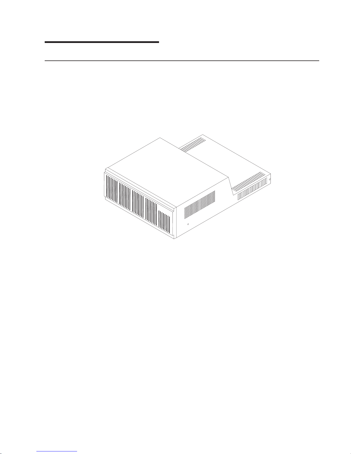
Chapter 3. Getting Started
Identifying the Parts
This section provides brief descriptions and reference pages for the controller
module’s primary components.
Controller Module Cabinets
The Controller Module is a rackmount unit (Figure 25):
Figure 25. Rackmount Cabinet
Removable Components
The controller module contains several removable, portable canisters, called
replaceable units
front or back of the unit. These FRUs include: a battery, controllers, power supplies,
and cooling fans. The controller module has a removable front cover.
Front View
The front of the controller module has the following primary components (Figure 26
on page 70):
v Front cover – a removable panel with holes for viewing the status lights and for
boosting air circulation. See “Gaining Access to the Controls” on page 72.
v Controller FRUs – two removable units that contain array controllers. See
“Controller Description” on page 89.
v Battery FRU – one removable unit that contains batteries and battery charger
circuitry. See “Battery Description” on page 112.
v Controller fan FRU – one removable unit that contains two cooling fans. See
“Controller Fan Description” on page 103.
(
FRUs
, pronounced “frews”), that you can access from either the
field
© Copyright IBM Corp. 1999 69
Page 100

Figure 26. Front View of Controller Module
Back View
The back of the controller module has the following primary components
(Figure 27):
v Connector plate – a protective panel that contains access holes for interface
connectors and jumpers. See Figure 27.
v Power supply FRUs – two removable units for the power supplies. See “Power
Supply Description” on page 118.
v Power supply fan FRU – one removable unit for the cooling fans. See “Power
Supply Fan Description” on page 107.
Figure 27. Back View of Controller Module
Internal Components
Inside the chassis, the controller module has the following primary components
(Figure 28 on page 71 and Figure 29 on page 71):
70 IBM 2102 Model F10 and Model D00 Service Guide
 Loading...