

Page 1

System Storage EXP5060 Quick Start Guide
This Quick Start Guide describes the basic procedure for installing, cabling, and configuring the IBM
System Storage™EXP5060 storage expansion enclosure.
Related documentation
For detailed information about the storage expansion enclosure, see the IBM System Storage EXP5060
Storage Expansion Enclosure Installation, User’s, and Maintenance Guide. For safety information, see the
multilingual IBM Safety Information document on the Documentation CD.
For more information about how to use a lift tool to install the storage expansion enclosure, see the
documentation that came with your lift tool.
For educational information about the EXP5060 and other IBM System Storage products, go to
http://ibmdsseriestraining.com/. For the latest information about IBM System Storage disk storage
systems, go to http://www.ibm.com/systems/support/storage/disk.
Installation overview
The installation of the storage expansion enclosure involves the following procedures:
1. “Installation guidelines”
2. “Ordering the lift tool” on page 3
3. “Unpacking the shipping box” on page 4
4. “Installing the support rails and rear brackets” on page 7
5. “Installing and removing the handles” on page 9
6. “Installing the storage expansion enclosure in the rack cabinet” on page 10
7. “Installing the DDMs” on page 12
8. “Installing the cables” on page 14
9. “Turning on the power” on page 19
10. “Installing the software” on page 20
11. “Obtaining information from the IBM Support Web site” on page 20
12. “Updating the storage subsystem controller firmware” on page 20
13. “Updating the storage expansion enclosure firmware” on page 20
®
Installation guidelines
Before you install the storage expansion enclosure in a rack cabinet, review the following guidelines:
v This product is to be installed and serviced only by qualified IBM service representatives.
v Because of the size and weight of the storage enclosure as shipped, a lift tool and a minimum of two
trained service technicians are required to push the enclosure out of its custom-designed package and
onto the lift tool.
v The storage expansion enclosure must not be installed in a rack position where the top of the unit is
above 32U or the bottom of the unit is above the 29U mark on the rack cabinet.
v Make sure that the room air temperature is below 25°C (77°F). The operating temperature for optimal
performance is 22°C (72°F) or lower.
v Do not block any air vents; usually 15 cm (6 in.) of space provides proper airflow.
Page 2

v Do not leave open spaces above or below an installed storage expansion enclosure in your rack cabinet.
To help prevent damage to storage expansion enclosure components, always install a blank filler panel
to cover the open space and to help ensure proper air circulation.
v Install the storage expansion enclosure only in a rack cabinet with perforated doors.
v Plan the device installation starting from the bottom of the rack cabinet.
v Install the heaviest device in the bottom of the rack cabinet.
v Do not extend more than one device out of the rack cabinet at the same time.
v Remove the rack doors and side panels to provide easier access during installation. Depending on the
rack location where the storage expansion enclosure will be installed, you might need to remove the
bracket that holds the door to the rack because the bracket might obstruct the storage expansion
enclosure handles.
v Connect the storage expansion enclosure to a properly grounded outlet. The storage expansion
enclosure accepts only 200 V - 240 V input sources. In addition, you might need to purchase a special
cable for the rack PDUs for the voltage and currents that the EXP5060 requires. If you do not have an
IBM System Storage 2101-200 rack with the supported PDUs and 60 A power cords, check your PDUs
or input sources to make sure that they can handle the EXP5060 voltage and currents.
v Do not overload the power outlet when you install multiple devices in the rack cabinet.
v Install the storage expansion enclosure in a rack cabinet that meets the following requirements:
– Minimum depth of 70 mm (2.76 in.) between the front support flange and the inside of the front
door.
– Minimum depth of 157 mm (6.18 in.) between the rear support flange and the inside of the rear
door.
– Minimum depth of 762 mm (30 in.) between the front and rear support flanges to support the use of
the cable-management arm.
v For more information about installing the storage expansion enclosure in a non-IBM rack, see the
“Specifications for non-IBM rack installation” section in the IBM System Storage EXP5060 Storage
Subsystem Installation, User’s, and Maintenance Guide.
102 kg (225 lbs)
56.7 kg (125 lbs)
(12 x 5)
(60X)
Attention:
1. Because of the size and weight of the storage expansion enclosure as shipped, a lift tool and a
minimum of two trained service technicians are required to push the enclosure out of its
custom-designed package and onto the lift tool. If a lift tool is not available, see Appendix G,
“Component weights”, in the IBM System Storage EXP5060 Storage Subsystem Installation, User’s, and
Maintenance Guide for additional information.
2. Before you move or relocate a rack that contains EXP5060 storage expansion enclosures, see
“Relocating a populated rack” in the IBM System Storage EXP5060 Storage Subsystem Installation, User’s,
and Maintenance Guide for additional information.
2
Page 3

Ordering the lift tool
The use of a lift tool is required when you install an EXP5060 in a rack cabinet and when you remove the
EXP5060 from a rack cabinet. Make sure that the lift tool is available on location at the time of the
installation. The ordering procedure for the lift tool varies depending on your location. Direct your
questions about these procedures to your regional representative.
World trade locations
The following ordering procedures are for world trade locations:
v Order the lift tool by using the parts ordering system, as you would with any other part.
v Use the part number 09P2481 when you order.
v Do not record parts usage.
v Return the lift tool to the parts center after you complete the installation or removal of the EXP5060.
United States locations
In the United States, call UPS Logistics at 800-528-6070 to order the lift tool or visit the MTS/Test
Equipment Service Center Web site on the IBM intranet at http://pokgsa.ibm.com/~tstesc/public/ for
additional information.
Note: The MTS/Test Equipment Service Center Web site can be accessed only by IBM employees with
access to the IBM intranet.
For the SSR branch and territory, the United States cannot order the lift tool through the parts ordering
system. UPS Logistics is used to ship and return the lift tool. Use the part number 09P2481 when you
order the lift tool.
You must provide the following information when you order the lift tool. This information is necessary to
ensure that the lift tool is delivered when you need it. Failure to provide this information might delay the
completion of the order request and the shipping request. It might also result in a time and date to return
the tool that is different from what you need.
v Phone number and customer contact
v Account code: 98577
v Time and date of delivery
v Accurate destination address with zip code
v Time and date of return pickup
Note: When you order the lift tool, you will receive an 18-inch load plate.
You must return the lift tool at the time that you schedule with UPS Logistics. If you need to change the
scheduled return time or date, contact UPS Logistics. You are responsible for ensuring that all of the
paperwork and components are packed and restored in the lift tool shipping container. Make sure that
the lift tool is functioning properly before you release the tool to UPS Logistics for return. You are
accountable for the lift tool until UPS Logistics picks up the lift tool for return delivery to their parts
storage facility. Contact your branch office tools coordinator or your region specialist if you have any
questions or concerns.
3
Page 4

Unpacking the shipping box
Important: Do not remove the storage expansion enclosure from the shipping box until the support rails
are installed in the rack cabinet. You must install the support rails in the rack cabinet before
you install the storage expansion enclosure.
The disk drive modules (DDMs) that come with the storage expansion enclosure are packaged in a
smaller box inside the shipping box. To unpack the shipping box, complete the following steps:
1. Remove the following items from the shipping box. Do not remove the EXP5060 from the shipping
box at this time.
v Box containing the mounting hardware kit
v Six full or empty boxes of DDMs
Note: The DDMs are packaged ten per box. The minimum order is 20 DDMs, so at least two of the
boxes are full. If you ordered less than the maximum number of 60 DDMs, one or more of
the boxes are empty.
v Box containing storage expansion enclosure handles
v Box containing the power cords, Fibre Channel signal cables, and documentation
2. Check the items in the preceding list to make sure that you received all the necessary parts. See the
“Inventory list” on page 5 for the parts that are included with the storage expansion enclosure.
4
Page 5

Inventory list
The following illustration and inventory list show the items that you need to install the storage expansion
enclosure in the rack cabinet. If any items are missing or damaged, contact your place of purchase.
Notes:
1. The illustration might differ slightly from your hardware.
2. Depending on your EXP5060 order, your shipping box might contain additional materials that are not
shown in the following illustration.
Fan
assembly (2)
Powe r
supply (2)
ESM (2)
Clip nuts (4)
M5 x 8 mm
screws (16)
Handles (4)
Rear brackets
Support rails
Bezel
Disk drive module
(20 or more)
Fibre Channel
cable
Drive drawer
assembly (5)
After you unpack the EXP5060, verify that you have the following items:
v 4U-high storage expansion enclosure (1)
– Drive drawer assemblies (5)
– Fan assemblies (2)
– Power supplies (2)
Storage
expansion
enclosure
Small Form-factor
Pluggable transceivers (pre-installed)
AC power cord (2)
5
Page 6

– ESMs (2)
v Handles (4), packaged in a smaller box inside the shipping box
v DDMs (20 or more, depending on your EXP5060 order), packaged in a smaller box inside the shipping
box
v Bezel (1)
v Fibre Channel signal cables (2 or more, depending on your EXP5060 order)
v SFP transceivers (2)
v Rack-mounting hardware kit (1), packaged in a smaller box inside the shipping box, including:
– Rails (2), right and left assembly
– Rear brackets (2)
– M5 black hex-head slotted screws (16)
Note: The screws are either preinstalled in the support rails or packaged in a plastic bag.
– Washers (8)
– Clip nuts (4)
Important: The EXP5060 does not ship with region-specific ac power cords. You must obtain the
IBM-approved power cords for your region. See the IBM System Storage EXP5060 Storage
Subsystem Installation, User’s, and Maintenance Guide for more information.
Tools
Before you install the storage expansion enclosure, the installation area must have an Internet connection,
and you must have the following tools:
v A cart to hold the storage expansion enclosure and its components
v Labels for the cable connectors
v A medium flat-blade screwdriver
v A No. 2 Phillips screwdriver or an M5 hex driver
v Anti-static protection
6
Page 7

Installing the support rails and rear brackets
Notes:
1. For proper weight distribution, install the support rails as low in the rack cabinet as possible.
2. The rack cabinet must have a minimum depth of 100 cm (40 in.).
To install the left and right support rails in the rack cabinet, complete the following steps. Use the front
and rear rack-mounting templates on pages 21 and 23 to align the support rails and rear brackets with
the correct rack holes. If the support rails will be installed above an existing storage subsystem or storage
expansion enclosure, position the EXP5060 support rails directly above it. If the support rails will be
installed below an existing storage subsystem or storage expansion enclosure, allow 178 mm (7 in.) of
vertical clearance for the EXP5060.
1. Make sure that the rack has already been installed.
2. Make sure that a stabilizer has been attached correctly to the bottom front of the rack to prevent the
rack from tipping forward while the storage expansion enclosure is being installed.
Refer to the installation and service guide, or equivalent, for the rack as required.
3. Locate the two support rails, eight M5 screws, and eight washers that are supplied with the storage
expansion enclosure.
Note: The screws and washers might already be attached to the support rails. If so, remove them
from the support rails.
4. Starting with the left support rail, loosen the two rail adjustment screws with a medium flat-blade
screwdriver. The adjustment screws are used to lock the support rails at a certain length.
Note: The support rails are not marked as left or right. However, each rail can be mounted correctly
on only one side of the rack cabinet. The rails should be mounted with the alignment pin at
the rear of the rack.
Rear
Screws
Front
Rear rack
cabinet rail
Front rack
cabinet rail
Screws
Support
rail lip
Rail adjustment
screws
5. Hold the front of the left support rail against the inside of the front rack cabinet support flange, and
extend the rear of the support rail until it makes contact with the rear rack cabinet support flange.
The alignment pins at the rear of the support rail slide into the mounting holes at the rear of the
rack cabinet. The wider end of the support rail must be positioned at the front of the rack cabinet.
6. From the front of the rack cabinet, with the support-rail flanges positioned inside the rack cabinet
support rail assemblies, insert two M5 screws with washers through the front of the cabinet and
screw them into the support rail front flange. Make sure that you use a washer when you install an
M5 screw through a square hole on a rack-mounting flange.
7
Page 8

Attention: Make sure that the screws are tight enough to support the weight of the storage
expansion enclosure, but do not completely tighten the screws yet.
7. Make sure that the holes in the rail above and below the top mounting screw are visible through the
holes of the rack flange and tighten the two M5 screws to secure the front of the rail to the rack
flange.
8. From the rear of the rack cabinet, insert two M5 screws with washers through the rear of the cabinet
and screw them into the support rail rear flange.
9. Tighten the two rail adjustment screws with a medium flat-blade screwdriver.
10. Repeat steps 4 on page 7 through 9 for the right support rail.
Note: Because the mounting holes on the rack are not always the same size as the mounting screws,
the lip of each of the support rails might not line up evenly. Make minor adjustments as
needed to make sure that the lip of the left and right support rails are lined up evenly on the
racks. Failure to do so will cause the storage expansion enclosure to fit unevenly in the rack.
11. Locate the two rear brackets, four M5 screws, four washers, and four clip nuts that are supplied with
the storage expansion enclosure.
12. Install the rear brackets at the rear of the rack as shown in the following illustration, using the M5
screws, washers, and clip nuts to secure the brackets to the rack mounting holes.
8
Page 9

Installing and removing the handles
Install the handles on the storage expansion enclosure before you move the unit onto the lift tool. After
you install the storage expansion enclosure in the rack cabinet and remove the handles, store the handles
for future use.
Installing the handles
Complete the following steps to install the handles on the storage expansion enclosure:
1. Locate the box of handles.
2. To install a handle on the storage expansion enclosure, place notch at the bottom of the handle in the
opening in the storage expansion enclosure chassis, and push the handle in and up until the latch at
the top of the handle secures the handle to the chassis.
3. Repeat step 2 for the three remaining handles.
Removing the handles
Before you install the storage expansion enclosure completely into a rack cabinet, you must remove the
handles. Complete the following steps to remove the handles from the storage expansion enclosure:
1. To remove a handle to the storage expansion enclosure, release the latch with your thumb and pull
down and away from the unit.
2. Repeat step 1 for the three remaining handles.
3. Store the handles for future use.
Thumb
latch
Handle
9
Page 10

Installing the storage expansion enclosure in the rack cabinet
To install the storage expansion enclosure, complete the following steps.
Note: For more information about how to use a lift tool, see the documentation that came with the lift
tool.
1. Prepare the storage expansion enclosure for installation:
a. Position the lift tool so that it is facing one side of the shipping box.
b. Remove the foam shipping material from the sides and ends of the storage expansion enclosure.
c. If necessary, cut away sides of the shipping box so that the lift tool has access to the storage
expansion enclosure.
d. Open the plastic bag and tuck it under the storage expansion enclosure. The plastic bag reduces
friction and makes it easier to slide the unit off of the shipping box onto the lift tool, and off of the
lift tool and into the rack cabinet.
e. Install the four handles on the sides of the storage expansion enclosure. See “Installing and
removing the handles” on page 9 for detailed instructions.
102 kg (225 lbs)
56.7 kg (125 lbs)
(12 x 5)
(60X)
Attention:
a. Because of the size and weight of the storage expansion enclosure as shipped, a lift tool and a
minimum of two trained service technicians are required to push the enclosure out of its
custom-designed package and onto the lift tool. If a lift tool is not available, see Appendix G,
“Component weights”, in the IBM System Storage EXP5060 Storage Subsystem Installation, User’s, and
Maintenance Guide for additional information.
b. Before you move or relocate a rack that contains EXP5060 storage expansion enclosures, see
“Relocating a populated rack” in the IBM System Storage EXP5060 Storage Subsystem Installation,
User’s, and Maintenance Guide for additional information.
2. With the help of a lift tool and a minimum of two trained service technicians, or a lift tool and
professional movers, slide the storage expansion enclosure off of the side of the shipping box and
onto the lift tool. Align it in front of the rack.
3. Put the rear edge of the storage expansion enclosure on the support rails.
4. Remove the two handles (one on each side) at the rear of the storage expansion enclosure. Do not
remove the front handles on the sides of the unit.
5. Slide the storage expansion enclosure halfway into the rack. Remove the remaining two handles at the
front of the unit.
10
Page 11

Rear
Front
6. Install and tighten two M5 screws on each side of the rack, above and below the top M5 screws, in
the front of the storage expansion enclosure to secure the storage expansion enclosure chassis to the
rack flanges.
7. Tighten all of the M5 screws to secure the rear of the storage expansion enclosure to the rack cabinet.
8. Turn the rear-bracket thumbscrews to attach the rear brackets to the sides of the storage expansion
enclosure. The screw holes are located about 51 mm (2 in.) from the rack flange.
Note: To align the thumbscrews with the holes in the unit, you might need to loosen the screws that
attach the rear brackets to the rack cabinet.
11
Page 12

Installing the DDMs
Important: The installation order within each drawer is from left to right in each row if you are facing
the front of the EXP5060. You must install DDMs in slots 1, 4, 7, and 10. Make sure that the
four DDMs in each row are adjacent to each other. The long edge of each DDM should touch
the DDM next to it. To maintain a uniform airflow across all drawers, the storage expansion
enclosure must be configured with a minimum of four DDMs in the front row of each drive
drawer.
Drive
drawer
Drives
Notes:
1. The drive drawers are preinstalled in the EXP5060, but the DDMs are shipped separately from the
drive drawers.
2. Make sure that you install the storage expansion enclosure in the rack cabinet before you install
DDMs in the storage expansion enclosure.
1
Drive
drawers
2
3
4
5
To install the DDMs in the drive drawers, complete the following steps:
1. Starting with the top drive drawer in the storage expansion enclosure, pull the levers on each side of
the drive drawer towards the center to release the drawer.
2. Pull the levers out from the storage expansion enclosure until the drawer is fully extended, but do not
remove it from the enclosure
3. Starting with the first DDM, raise the DDM handle to the vertical position.
12
Page 13

Latch
Slots
Raised
buttons
4. Align the raised buttons on the sides with the matching slots in the DDM channel on the drawer.
Lower the DDM down onto the drawer, and rotate the DDM handle until the DDM snaps into place
under the DDM release lever.
Notes:
a. If the DDM does not seem not fully seated into the drive connector on the disk drawer, apply
downward pressure to the rear of the drive as you install it.
b. If the storage expansion enclosure is turned on, you must wait at least 90 seconds after you install
each DDM in the drive drawer. Otherwise, the storage expansion enclosure might not recognize
the new DDM, recognize the DDM as failed, or recognize the drive as incompatible. If this
happens, unlatch the DDM, wait 90 seconds, and latch the DDM again.
5. Install the other DDMs in rows from left to right until the drive drawer has a minimum of four
DDMs in the front row of the drive drawer.
6. Push the drive drawer into the storage expansion enclosure until it clicks and close the levers on each
side of the drawer.
Attention: Make sure you push both levers back against the drive drawer completely so that the
drive drawer is closed. If the drive drawer is not completely closed, excess airflow through the unit
might cause damage to the DDMs. If the drive drawer is not completely closed, you will not be able
to open another drawer. If you try to force open another drawer, both drawers might be damaged.
7. Repeat steps 1 on page 12 through 6 for each drive drawer in the configuration.
8. Position the bezel in front of the storage expansion enclosure as shown in the following illustration.
9. Align the tabs on the top and bottom of the bezel with the slots on the front of the storage expansion
enclosure, and align the pins on the side of the bezel with the holes in the storage expansion
enclosure. Push the bezel into the front of the unit until the latches on the sides of the bezel lock it in
place.
Front bezel Latches
13
Page 14

Installing the cables
Use the information in this section to cable one or two storage expansion enclosures and a storage
subsystem, with or without drive-side trunking.
For more information about cabling configurations, see either the IBM System Storage EXP5060 Installation,
User’s, and Maintenance Guide that came with the storage expansion enclosure or the IBM System Storage
DS5100 and DS5300 Installation, User’s, and Maintenance Guide.
The EXP5060 is compatible with DS5100 and DS5300 storage subsystems. The following cabling
instructions are shown with the assumption that the EXP5060 will be connected to a DS5100 or DS5300
storage subsystem.
The following illustration shows the drive ports on each controller in the DS5100 and DS5300 storage
subsystems. If you have not already installed the DS5100 or DS5300 storage subsystem, you must do so
now. For more information about installing these storage subsystems, see the IBM System Storage DS5100
and DS5300 Installation, User’s, and Maintenance Guide.
Controller A drive ports
Controller B drive ports
14
Page 15
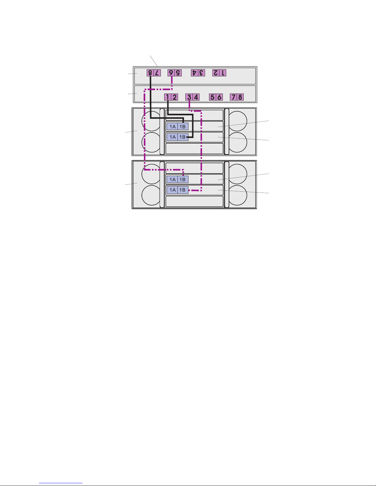
Cabling two storage expansion enclosures and a storage subsystem
Statement 3:
CAUTION:
When laser products (such as CD-ROMs, DVD drives, fiber optic devices, or transmitters) are
installed, note the following:
v Do not remove the covers. Removing the covers of the laser product could result in exposure to
hazardous laser radiation. There are no serviceable parts inside the device.
v Use of controls or adjustments or performance of procedures other than those specified herein
might result in hazardous radiation exposure.
DANGER
Some laser products contain an embedded Class 3A or Class 3B laser diode. Note the following.
Laser radiation when open. Do not stare into the beam, do not view directly with optical
instruments, and avoid direct exposure to the beam.
To cable two storage expansion enclosures to a storage subsystem, complete the following steps:
1. The Small Form-factor Pluggable transceivers (SFPs) are preinstalled in the Fibre Channel host ports
in the storage subsystem and the EXP5060. Make sure the SFPs are seated completely in the host
ports.
15
Page 16
Storage
subsystem
Controller A
Controller B
ESM A
EXP5060 No. 1
ESM B
ESM A
EXP5060 No. 2
ESM B
2. Connect a fiber-optic cable from drive port 8 on controller A in the storage subsystem to port 1B on
ESM A in EXP5060 one.
3. Connect a fiber-optic cable from drive port 1 of controller B in the storage subsystem to port 1B on
ESM B in EXP5060 one.
4. Connect a fiber-optic cable from drive port 6 on controller A in the storage subsystem to port 1B on
ESM A in EXP5060 two.
5. Connect a fiber-optic cable from drive port 3 on controller B in the storage subsystem to port 1B on
ESM B in EXP5060 two.
Note: For more information about cabling configurations, see the IBM System Storage EXP5060
Installation, User’s, and Maintenance Guide that came with the storage expansion enclosure.
16
Page 17

Cabling two storage expansion enclosures and a storage subsystem
with drive-side trunking
Statement 3:
CAUTION:
When laser products (such as CD-ROMs, DVD drives, fiber optic devices, or transmitters) are
installed, note the following:
v Do not remove the covers. Removing the covers of the laser product could result in exposure to
hazardous laser radiation. There are no serviceable parts inside the device.
v Use of controls or adjustments or performance of procedures other than those specified herein
might result in hazardous radiation exposure.
DANGER
Some laser products contain an embedded Class 3A or Class 3B laser diode. Note the following.
Laser radiation when open. Do not stare into the beam, do not view directly with optical
instruments, and avoid direct exposure to the beam.
Drive-side trunking uses the right side of the expansion ports on the rear of the storage expansion
enclosure to allow the full bandwidth potential of the EXP5060 storage expansion enclosure.
To cable two storage expansion enclosures to a storage subsystem with drive-side trunking, complete the
following steps:
1. The Small Form-factor Pluggable transceivers (SFPs) are preinstalled in the Fibre Channel host ports
in the storage subsystem and the EXP5060. Make sure the SFPs are seated completely in the host
ports.
17
Page 18

Storage
subsystem
Controller A
Controller B
EXP5060 No. 1
EXP5060 No. 2
6
1
1A
1A
1A 1B
1A
5
4
4
3
2
2A 2B
1B
1B
2A
2A
1B
2A
7
8
2
2B
2B
2B
1
8
5
7
6
ESM A
ESM B
ESM A
ESM B
3
2. Connect a fiber-optic cable from drive port 8 on controller A in the storage subsystem to port 1B on
ESM A in EXP5060 one.
3. Connect a fiber-optic cable from drive port 7 on controller A in the storage subsystem to port 2B on
ESM A in EXP5060 one.
4. Connect a fiber-optic cable from drive port 1 of controller B in the storage subsystem to port 1B on
ESM B in EXP5060 one.
5. Connect a fiber-optic cable from drive port 2 of controller B in the storage subsystem to port 2B on
ESM B in EXP5060 one.
6. Connect a fiber-optic cable from drive port 6 on controller A in the storage subsystem to port 1B on
ESM A in EXP5060 two.
7. Connect a fiber-optic cable from drive port 5 on controller A in the storage subsystem to port 2B on
ESM A in EXP5060 two.
8. Connect a fiber-optic cable from drive port 3 on controller B in the storage subsystem to port 1B on
ESM B in EXP5060 two.
9. Connect a fiber-optic cable from drive port 4 on controller B in the storage subsystem to port 2B on
ESM B in EXP5060 two.
Note: For more information about cabling configurations, see the IBM System Storage EXP5060
Installation, User’s, and Maintenance Guide that came with the storage expansion enclosure.
18
Page 19

Turning on the power
Statement 5:
CAUTION:
The power control button on the device and the power switch on the power supply do not turn off the
electrical current supplied to the device. The device also might have more than one power cord. To
remove all electrical current from the device, ensure that all power cords are disconnected from the
power source.
2
1
Important: You must follow the power sequence in the order shown in the following procedure. To
establish power redundancy for enclosures with two power supplies, use at least two power
distribution units (PDUs) in the rack cabinet. Split the power connections from each enclosure
into the separate PDUs. Then, connect the PDUs to external power receptacles that are on
different circuits.
The storage expansion enclosure accepts only 200 V - 240 V input sources. In addition, you
might need to purchase a special cable for the rack PDUs for the voltage and currents that the
EXP5060 requires. If you do not have an IBM System Storage 2101-200 rack with the
supported PDUs and 60 A power cords, check your PDUs or input sources to make sure that
they can handle the EXP5060 voltage and currents.
To turn on the storage expansion enclosure power, complete the following steps:
1. Turn off all the power switches on the rear of the storage expansion enclosure. Make sure all of the
power cords are connected.
2. If the main circuit breaker switches in the rack cabinet are turned off, turn them on.
3. Turn on the power switch on each storage expansion enclosure.
4. Turn on both power switches on the storage subsystem.
Note: When you turn off the power to the storage subsystem and storage expansion enclosure,
complete the preceding steps in reverse order. Turn off the power to the storage subsystem
first; then, turn off the power to the storage expansion enclosures.
The following illustration shows the power supplies and the rear view of the EXP5060.
ESM A
ESM B
Powe r
supplies
19
Page 20

Installing the software
For information about installing the DS Storage Manager software, see the IBM System Storage DS5100 and
DS5300 Installation, User’s, and Maintenance Guide.
Note: The DS Storage Manager version must be 10.60.x5.11 or higher.
Obtaining information from the IBM Support Web site
The IBM System Storage documentation that is described in this Quick Start Guide and other IBM System
Storage information is on the IBM support Web site. To access the latest documentation, downloads, and
other technical updates on the IBM support Web site, complete the following steps.
Note: Changes are made periodically to the IBM Web site. Procedures for locating firmware and
documentation might vary slightly from what is described in this document.
1. Go to http://www.ibm.com/systems/storage/support/.
2. Under Select your product,intheProduct Family field, click Disk systems.
3. In the Product field, click EXP5060, and then click Go.
4. Under Support & downloads, click the applicable support category.
Note: For detailed information about device-driver and firmware versions, make sure that you read the
readme files that are posted with each package.
Updating the storage subsystem controller firmware
The storage controller firmware must be version 7.60.13.05 or later. For the latest firmware version, go to
the IBM Systems Storage support Web site at http://www.ibm.com/systems/support/storage/disk/.
In the DS Storage Manager Subsystem Management Window, in the Physical tab, click Advanced >
Maintenance > Download > Controller Firmware.
Updating the storage expansion enclosure firmware
For the latest firmware version, go to the IBM Systems Storage support Web site at http://
www.ibm.com/systems/support/storage/disk/.
In the DS Storage Manager Subsystem Management Window, in the Physical tab, click Advanced >
Maintenance > Download.FromtheDownload menu, update the firmware in the following order:
1. To update the ESM firmware, select ESM Firmware.
2. To update the ATA translator firmware, select Download Drive Firmware.
3. To update the drive firmware, select Download Drive Firmware.
20
Page 21

4U
4U
3U
2U
1U
Install second
Install first
Install second Install second
Install second
Install first
FRONT
Rack Mounting
Template
Rail assembly
(front left)
Rail assembly
(front right)
3U
2U
1U
Install first Install first
0U
0U
21
Page 22

22
Page 23

4U
4U
Rear bracket Rear bracket
3U
2U
1U
Rack Mounting
Rail assembly
(rear left)
3U
REAR
Template
2U
Rail assembly
(rear right)
1U
Rail mounting guide
0U
®
Printed in the U.S.A
0U
23
Page 24

First Edition (October 2009)
Printed in the U.S.A.
IBM and System Storage are trademarks of the IBM Corporation in the United States, other countries, or both.
®
Microsoft
and Windows®are trademarks of Microsoft Corporation in the United States, other countries, or both.
© Copyright International Business Machines Corporation 2009.
US Government Users Restricted Rights – Use, duplication or disclosure restricted by GSA ADP Schedule Contract
with IBM Corp.
(1P) P/N: 59Y7018
 Loading...