

Page 1

IBM System Storage EXN1000 Storage Expansion Unit
Hardw are an d Service Guide
GC26-7802-02
Page 2

Page 3

IBM System Storage EXN1000 Storage Expansion Unit
Hardw are an d Service Guide
GC26-7802-02
Page 4

Note:
Before using this information and the product it supports, be sure to read the general information in “Notices”
on page 51.
The following paragraph does not apply to any country (or region) where such provisions are inconsistent with local
law.
INTERNATIONAL BUSINESS MACHINES CORPORATION PROVIDES THIS PUBLICATION “AS IS” WITHOUT
WARRANTY OF ANY KIND, EITHER EXPRESS OR IMPLIED, INCLUDING, BUT NOT LIMITED TO, THE IMPLIED
WARRANTIES OF MERCHANTABILITY OR FITNESS FOR A PARTICULAR PURPOSE. Some states (or regions) do
not allow disclaimer of express or implied warranties in certain transactions; therefore, this statement may not apply
to you.
Order publications through your IBM representative or the IBM branch office serving your locality.
© Copyright International Business Machines Corporation 2005, 2007. All rights reserved.
US Government Users Restricted Rights – Use, duplication or disclosure restricted by GSA ADP Schedule Contract
with IBM Corp.
Page 5

Safety and environmental notices
This section contains information about:
v “Safety notices and labels”
v “Laser safety” on page vii
v “Rack safety” on page viii
v “Product recycling and disposal” on page xi
v “Battery return program” on page xii
v “Fire suppression systems” on page xiii
Safety notices and labels
When using this product, observe the danger, caution, and attention notices
contained in this guide. The notices are accompanied by symbols that
represent the severity of the safety condition.
The following sections define each type of safety notice and provide
examples.
The following notices and statements are used in IBM® documents. They are
listed below in order of increasing severity of potential hazards. Follow the
links for more detailed descriptions and examples of the danger, caution, and
attention notices in the sections that follow.
v Note: These notices provide important tips, guidance, or advice.
v “Attention notices” on page vii: These notices indicate potential damage to
programs, devices, or data.
v “Caution notices” on page vi: These statements indicate situations that can
be potentially hazardous to you.
v “Danger notices”: These statements indicate situations that can be
potentially lethal or extremely hazardous to you. Safety labels are also
attached directly to products to warn of these situations.
v In addition to these notices, “Labels” on page vi may be attached to the
product to warn of potential hazards.
Danger notices
A danger notice calls attention to a situation that is potentially lethal or
extremely hazardous to people. A lightning bolt symbol accompanies a danger
notice to represent a dangerous electrical condition. A sample danger notice
follows.
© Copyright IBM Corp. 2005, 2007 iii
Page 6

DANGER
An
electrical outlet that is not correctly wired could place
hazardous voltage on metal parts of the system or the devices
that attach to the system. It is the responsibility of the
customer to ensure that the outlet is correctly wired and
grounded to prevent an electrical shock. (D004)
A comprehensive danger notice provides instructions on how to avoid shock
hazards when servicing equipment. Unless instructed otherwise, follow the
procedures in the following danger notice.
iv
Page 7

DANGER
When
working on or around the system, observe the following
precautions:
Electrical voltage and current from power, telephone, and
communication cables are hazardous. To avoid a shock hazard:
v Connect power to this unit only with the IBM provided
power cord. Do not use the IBM provided power cord for
any other product.
v Do not open or service any power supply assembly.
v Do not connect or disconnect any cables or perform
installation, maintenance, or reconfiguration of this product
during an electrical storm.
v The product might be equipped with multiple power cords.
To remove all hazardous voltages, disconnect all power
cords.
v Connect all power cords to a properly wired and grounded
electrical outlet. Ensure outlet supplies proper voltage and
phase rotation according to the system rating plate.
v Connect any equipment that will be attached to this product
to properly wired outlets.
v When possible, use one hand only to connect or disconnect
signal cables.
v Never turn on any equipment when there is evidence of fire,
water, or structural damage.
v Disconnect the attached power cords, telecommunications
systems, networks, and modems before you open the device
covers, unless instructed otherwise in the installation and
configuration procedures.
v Connect and disconnect cables as described below when
installing, moving, or opening covers on this product or
attached devices.
Disconnect:
To
1. Turn off everything (unless instructed otherwise).
2. Remove power cords from the outlet.
3. Remove signal cables from connectors.
4. Remove all cables from devices.
Connect:
To
1. Turn off everything (unless instructed otherwise).
2. Attach all cables to devices.
3. Attach signal cables to the connectors.
4. Attach power cords to the outlets.
5. Turn on the devices.
(D005)
Safety and environmental notices v
Page 8

Labels
As an added precaution, safety labels are often installed directly on products
or product components to warn of potential hazards.
The actual product safety labels may differ from these sample safety labels:
(L001)
(L003)
DANGER
Hazardous
voltage, current, or energy levels are
present inside any component that has this label
attached. Do not open any cover or barrier that
contains this label.
DANGER
Multiple
power cords. The product might be equipped
with multiple power cords. To remove all hazardous
voltages, disconnect all power cords.
Caution notices
A caution notice calls attention to a situation that is potentially hazardous to
people because of some existing condition. A caution notice can be
accompanied by different symbols, as in the examples below:
If the symbol is... It means...
A hazardous electrical condition with less severity than
electrical danger.
A generally hazardous condition not represented by
other safety symbols.
A hazardous condition due to the use of a laser in the
product. Laser symbols are always accompanied by the
classification of the laser as defined by the U. S.
Department of Health and Human Services (for
example, Class I, Class II, and so forth).
vi
Page 9

Attention notices
Laser safety
An attention notice indicates the possibility of damage to a program, device,
or system, or to data. An exclamation point symbol may accompany an
attention notice, but is not required. A sample attention notice follows:
Attention: Do not bend a fibre cable to a radius less than 5 cm (2
in.); you can damage the cable. Tie wraps are not recommended for
optical cables because they can be easily overtightened, causing
damage to the cable.
When using an NVRAM5 or NVRAM6 cluster media converter, the storage
system must be installed in a restricted access location.
CAUTION:
This product contains a Class 1M laser. Do not view directly with
optical instruments. (C028)
This equipment contains Class 1 laser products, and complies with FDA
radiation Performance Standards, 21 CFR Subchapter J and the international
laser safety standard IEC 825-2.
CAUTION:
Data processing environments can contain equipment transmitting on
system links with laser modules that operate at greater than Class 1
power levels. For this reason, never look into the end of an optical
fiber cable or open receptacle. (C027)
Attention: In the United States, use only SFP or GBIC optical transceivers
that comply with the FDA radiation performance standards, 21 CFR
Subchapter J. Internationally, use only SFP or GBIC optical transceivers that
comply with IEC standard 825–1. Optical products that do not comply with
these standards may produce light that is hazardous to the eyes.
Usage restrictions
The optical ports of the modules must be terminated with an optical
connector or with a dust plug.
Safety and environmental notices vii
Page 10

Rack safety
Rack installation
DANGER
Observe
the following precautions when working on or
around your IT rack system:
v Heavy equipment - personal injury or equipment damage
might result if mishandled.
v Always lower the leveling pads on the rack cabinet.
v Always install stabilizer brackets on the rack cabinet.
v To avoid hazardous conditions due to uneven mechanical
loading, always install the heaviest devices in the bottom of
the rack cabinet. Always install servers and optional devices
starting from the bottom of the rack cabinet.
v Rack-mounted devices are not to be used as shelves or work
spaces. Do not place objects on top of rack-mounted
devices.
viii
v Each rack cabinet might have more than one power cord. Be
sure to disconnect all power cords in the rack cabinet when
directed to disconnect power during servicing.
v Connect all devices installed in a rack cabinet to power
devices installed in the same rack cabinet. Do not plug a
power cord from a device installed in one rack cabinet into
a power device installed in a different rack cabinet.
v An electrical outlet that is not correctly wired could place
hazardous voltage on the metal parts of the system or the
devices that attach to the system. It is the responsibility of
the customer to ensure that the outlet is correctly wired and
grounded to prevent an electrical shock.
(R001 part 1 of 2
Page 11

CAUTION:
v Do not install a unit in a rack where the internal rack ambient
temperatures will exceed the manufacturer’s recommended ambient
temperature for all your rack-mounted devices.
v Do not install a unit in a rack where the air flow is compromised. Ensure
that air flow is not blocked or reduced on any side, front, or back of a
unit used for air flow through the unit.
v Consideration should be given to the connection of the equipment to the
supply circuit so that overloading of the circuits does not compromise the
supply wiring or overcurrent protection. To provide the correct power
connection to a rack, refer to the rating labels located on the equipment
in the rack to determine the total power requirement of the supply
circuit.
v (For sliding drawers.) Do not pull out or install any drawer or feature if the
rack stabilizer brackets are not attached to the rack. Do not pull out more
than one drawer at a time. The rack might become unstable if you pull
out more than one drawer at a time.
v (For fixed drawers) This drawer is a fixed drawer and should not be moved
for servicing unless specified by manufacturer. Attempting to move the
drawer partially or completely out of the rack may cause the rack to
become unstable or cause the drawer to fall out of the rack.
(R001
part 2 of 2)
Safety and environmental notices ix
Page 12

Rack relocation (19″ rack)
CAUTION:
Removing components from the upper positions in the rack cabinet
improves rack stability during relocation. Follow these general guidelines
whenever you relocate a populated rack cabinet within a room or building:
v Reduce the weight of the rack cabinet by removing equipment starting at
the top of the rack cabinet. When possible, restore the rack cabinet to the
configuration of the rack cabinet as you received it. If this configuration
is not known, you must do the following:
– Remove all devices in the 32U position and above.
– Ensure that the heaviest devices are installed in the bottom of the rack
cabinet.
– Ensure that there are no empty U-levels between devices installed in
the rack cabinet below the 32U level.
– If the rack cabinet you are relocating is part of a suite of rack cabinets,
detach the rack cabinet from the suite.
– Inspect the route that you plan to take when moving the rack to
eliminate potential hazards.
– Verify that the route that you choose can support the weight of the
loaded rack cabinet. Refer to the documentation that came with your
rack cabinet for the weight of a loaded rack cabinet.
– Verify that all door openings are at least 760 x 2030 mm (30 x 80 in.).
– Ensure that all devices, shelves, drawers, doors, and cables are secure.
– Ensure that the four leveling pads are raised to their highest position.
– Ensure that there is no stabilizer bracket installed on the rack cabinet
during movement.
– Do not use a ramp inclined at more than ten degrees.
– Once the rack cabinet is in the new location, do the following:
- Lower the four leveling pads.
- Install stabilizer brackets on the rack cabinet.
- If you removed any devices from the rack cabinet, repopulate the
rack cabinet from the lowest position to the highest position.
If a long distance relocation is required, restore the rack cabinet to the
–
configuration of the rack cabinet as you received it. Pack the rack
cabinet in the original packaging material, or equivalent. Also, lower
the leveling pads to raise the casters off of the pallet and bolt the rack
cabinet to the pallet.
(R002)
x
Page 13

Product recycling and disposal
This unit must be recycled or discarded according to applicable local and
national regulations. IBM encourages owners of information technology (IT)
equipment to responsibly recycle their equipment when it is no longer
needed. IBM offers a variety of product return programs and services in
several countries to assist equipment owners in recycling their IT products.
Information on IBM product recycling offerings can be found on IBM’s
Internet site at:
www.ibm.com/ibm/environment/products/prp.shtml
Esta unidad debe reciclarse o desecharse de acuerdo con lo establecido en la
normativa nacional o local aplicable. IBM recomienda a los propietarios de
equipos de tecnología de la informacion (TI) que reciclen responsablemente
sus equipos cuando éstos ya no les sean utiles. IBM dispone de una serie de
programas y servicios de devolucion de productos en varios países, a fin de
ayudar a los propietarios de equipos a reciclar sus productos de TI. Se puede
encontrar informacion sobre las ofertas de reciclado de productos de IBM en
el sitio web de IBM www.ibm.com/ibm/environment/products/prp.shtml.
Notice: This mark applies only to countries within the European Union (EU)
and Norway.
This appliance is labelled in accordance with European Directive 2002/96/EC
concerning waste electrical and electronic equipment (WEEE). The Directive
determines the framework for the return and recycling of used appliances as
applicable throughout the European Union. This label is applied to various
products to indicate that the product is not to be thrown away, but rather
reclaimed upon end of life per this Directive.
Safety and environmental notices xi
Page 14
In accordance with the European WEEE Directive, electrical and electronic
equipment (EEE) is to be collected separately and to be reused, recycled, or
recovered at end of life. Users of EEE with the WEEE marking per Annex IV
of the WEEE Directive, as shown above, must not dispose of end of life EEE
as unsorted municipal waste, but use the collection framework available to
customers for the return, recycling and recovery of WEEE. Customer
participation is important to minimize any potential effects of EEE on the
environment and human health due to the potential presence of hazardous
substances in EEE. For proper collection and treatment, contact your local IBM
representative.
Battery return program
This product may contain sealed lead acid, nickel cadmium, nickel metal
hydride, lithium, or lithium ion battery. Consult your user manual or service
manual for specific battery information. The battery must be recycled or
disposed of properly. Recycling facilities may not be available in your area.
For information on disposal of batteries outside the United States, contact
your local waste disposal facility or go to the following Web site:
xii
www.ibm.com/ibm/environment/products/batteryrecycle.shtml
In the United States, IBM has established a return process for reuse, recycling,
or proper disposal of used IBM sealed lead acid, nickel cadmium, nickel metal
hydride, and other battery packs from IBM Equipment. For information on
proper disposal of these batteries, contact IBM at 1-800-426-4333. Please have
the IBM part number listed on the battery available prior to your call.
For Taiwan:
Page 15

For the European Union:
Note: This mark applies only to countries within the European Union (EU).
Batteries or packaging for batteries are labeled in accordance with European
Directive 2006/66/EC concerning batteries and accumulators and waste
batteries and accumulators. The Directive determines the framework for the
return and recycling of used batteries and accumulators as applicable
throughout the European Union. This label is applied to various batteries to
indicate that the battery is not to be thrown away, but rather reclaimed upon
end of life per this Directive.
In accordance with the European Directive 2006/66/EC, batteries and
accumulators are labeled to indicate that they are to be collected separately
and recycled at end of life. The label on the battery may also include a
chemical symbol for the metal concerned in the battery (Pb for lead, Hg for
mercury and Cd for cadmium). Users of batteries and accumulators must not
dispose of batteries and accumulators as unsorted municipal waste, but use
the collection framework available to customers for the return, recycling and
treatment of batteries and accumulators. Customer participation is important
to minimize any potential effects of batteries and accumulators on the
environment and human health due to the potential presence of hazardous
substances. For proper collection and treatment, contact your local IBM
representative.
Fire suppression systems
A fire suppression system is the responsibility of the customer. The customer’s
own insurance underwriter, local fire marshal, or a local building inspector, or
both, should be consulted in selecting a fire suppression system that provides
the correct level of coverage and protection. IBM designs and manufactures
equipment to internal and external standards that require certain
environments for reliable operation. Because IBM does not test any equipment
Safety and environmental notices xiii
Page 16

for compatibility with fire suppression systems, IBM does not make
compatibility claims of any kind nor does IBM provide recommendations on
fire suppression systems.
xiv
Page 17

Contents
Safety and environmental notices . . . . . . . . . . . . . . . . . . . . . . . iii
Safety notices and labels . . . . . . . . . . . . . . . . . . . . . . . . . . . iii
Danger notices . . . . . . . . . . . . . . . . . . . . . . . . . . . . . iii
Labels . . . . . . . . . . . . . . . . . . . . . . . . . . . . . . . .vi
Caution notices . . . . . . . . . . . . . . . . . . . . . . . . . . . . .vi
Attention notices . . . . . . . . . . . . . . . . . . . . . . . . . . . . vii
Laser safety . . . . . . . . . . . . . . . . . . . . . . . . . . . . . . . vii
Usage restrictions . . . . . . . . . . . . . . . . . . . . . . . . . . . . vii
Rack safety . . . . . . . . . . . . . . . . . . . . . . . . . . . . . . . viii
Rack installation . . . . . . . . . . . . . . . . . . . . . . . . . . . . viii
Rack relocation (19″ rack) . . . . . . . . . . . . . . . . . . . . . . . . . .x
Product recycling and disposal . . . . . . . . . . . . . . . . . . . . . . . . .xi
Battery return program . . . . . . . . . . . . . . . . . . . . . . . . . . . xii
For the European Union: . . . . . . . . . . . . . . . . . . . . . . . . . xiii
Fire suppression systems . . . . . . . . . . . . . . . . . . . . . . . . . xiii
Figures . . . . . . . . . . . . . . . . . . . . . . . . . . . . . . . . xix
Tables . . . . . . . . . . . . . . . . . . . . . . . . . . . . . . . . xxi
About this document . . . . . . . . . . . . . . . . . . . . . . . . . . . xxiii
Who should read this document . . . . . . . . . . . . . . . . . . . . . . . xxiii
Supported features . . . . . . . . . . . . . . . . . . . . . . . . . . . . xxiii
How this document is organized . . . . . . . . . . . . . . . . . . . . . . . xxiii
Getting information, help, and service . . . . . . . . . . . . . . . . . . . . . xxiv
Before you call . . . . . . . . . . . . . . . . . . . . . . . . . . . . xxiv
Using the documentation . . . . . . . . . . . . . . . . . . . . . . . . . xxiv
Web sites . . . . . . . . . . . . . . . . . . . . . . . . . . . . . . xxv
Hardware service and support . . . . . . . . . . . . . . . . . . . . . . . xxv
Supported servers and operating systems . . . . . . . . . . . . . . . . . . . xxv
Firmware updates . . . . . . . . . . . . . . . . . . . . . . . . . . . xxv
Conventions and terminology used in this document . . . . . . . . . . . . . . . . . xxv
Terminology . . . . . . . . . . . . . . . . . . . . . . . . . . . . . xxvi
Command conventions . . . . . . . . . . . . . . . . . . . . . . . . . xxvi
Formatting conventions . . . . . . . . . . . . . . . . . . . . . . . . . xxvi
Keyboard conventions . . . . . . . . . . . . . . . . . . . . . . . . . xxvii
How to send your comments . . . . . . . . . . . . . . . . . . . . . . . . xxviii
Chapter 1. Preparing for the installation . . . . . . . . . . . . . . . . . . . . .1
Required manuals, tools and equipment . . . . . . . . . . . . . . . . . . . . . .1
Required tools and equipment for installation . . . . . . . . . . . . . . . . . . .1
Handling static-sensitive devices . . . . . . . . . . . . . . . . . . . . . . . .1
Planning and organizing the installation . . . . . . . . . . . . . . . . . . . . . .2
Hardware specifications . . . . . . . . . . . . . . . . . . . . . . . . . .3
Checking shipment package contents . . . . . . . . . . . . . . . . . . . . . .4
© Copyright IBM Corp. 2005, 2007 xv
Page 18

Rules for installing EXN1000 expansion units in a rack . . . . . . . . . . . . . . . .4
Guide to the installation process . . . . . . . . . . . . . . . . . . . . . . .5
Before you begin your installation . . . . . . . . . . . . . . . . . . . . . . . .7
EXN1000 expansion unit numbering . . . . . . . . . . . . . . . . . . . . . .8
Drive addressing . . . . . . . . . . . . . . . . . . . . . . . . . . . .9
Speed setting . . . . . . . . . . . . . . . . . . . . . . . . . . . . .10
Supported disk drives . . . . . . . . . . . . . . . . . . . . . . . . . .11
Drive bay requirements . . . . . . . . . . . . . . . . . . . . . . . . . .11
Chapter 2. Connecting an EXN1000 expansion unit . . . . . . . . . . . . . . . . .13
Handling fiber-optic cables . . . . . . . . . . . . . . . . . . . . . . . . . .13
Connecting EXN1000 expansion units . . . . . . . . . . . . . . . . . . . . . .14
EXN1000 expansion unit cabling requirements . . . . . . . . . . . . . . . . . .14
Connecting the expansion unit directly to the N series storage system . . . . . . . . .14
Connecting the expansion unit to other expansion units . . . . . . . . . . . . . .15
Grounding EXN1000 expansion units . . . . . . . . . . . . . . . . . . . . . .15
Connecting the EXN1000 expansion unit to a power source . . . . . . . . . . . . . . .15
Hot-adding an EXN1000 expansion unit to an existing loop . . . . . . . . . . . . . . .15
Error messages . . . . . . . . . . . . . . . . . . . . . . . . . . . . .17
Chapter 3. Monitoring the EXN1000 expansion unit . . . . . . . . . . . . . . . . .19
Monitoring the front operation panel . . . . . . . . . . . . . . . . . . . . . .19
Location of LEDs . . . . . . . . . . . . . . . . . . . . . . . . . . . .20
Monitoring the disk shelf ID . . . . . . . . . . . . . . . . . . . . . . . .20
LED status on the front operation panel . . . . . . . . . . . . . . . . . . . .20
Front operation panel console error messages . . . . . . . . . . . . . . . . . . .21
Monitoring the AT-FCX modules . . . . . . . . . . . . . . . . . . . . . . . .22
Location of the module LEDs . . . . . . . . . . . . . . . . . . . . . . . .22
LED status on the AT-FCX . . . . . . . . . . . . . . . . . . . . . . . . .23
AT-FCX console error messages . . . . . . . . . . . . . . . . . . . . . . .23
Monitoring the power supply . . . . . . . . . . . . . . . . . . . . . . . . .24
Location of LEDs . . . . . . . . . . . . . . . . . . . . . . . . . . . .25
Power supply console error messages . . . . . . . . . . . . . . . . . . . . .26
Monitoring the ATA disk . . . . . . . . . . . . . . . . . . . . . . . . . .27
Location of LEDs . . . . . . . . . . . . . . . . . . . . . . . . . . . .27
Chapter 4. Replacing EXN1000 expansion unit devices . . . . . . . . . . . . . . .29
Removing an EXN1000 expansion unit . . . . . . . . . . . . . . . . . . . . . .29
Removing an EXN1000 expansion unit from a single EXN1000 expansion unit configuration . . .30
Removing an EXN1000 expansion unit from a loop . . . . . . . . . . . . . . . . .31
Replacing a disk in an EXN1000 expansion unit . . . . . . . . . . . . . . . . . . .32
Preparing to replace a disk . . . . . . . . . . . . . . . . . . . . . . . . .32
Removing a disk . . . . . . . . . . . . . . . . . . . . . . . . . . . .32
Installing a disk . . . . . . . . . . . . . . . . . . . . . . . . . . . .33
Replacing a power supply in an EXN1000 expansion unit . . . . . . . . . . . . . . .33
Rules for replacing power supplies . . . . . . . . . . . . . . . . . . . . . .34
Removing a power supply . . . . . . . . . . . . . . . . . . . . . . . . .34
Installing a power supply . . . . . . . . . . . . . . . . . . . . . . . . .35
Replacing an AT-FCX module . . . . . . . . . . . . . . . . . . . . . . . . .35
Connectors in an AT-FCX . . . . . . . . . . . . . . . . . . . . . . . . .36
xvi
Page 19

For detailed information . . . . . . . . . . . . . . . . . . . . . . . . . .36
Removing a module . . . . . . . . . . . . . . . . . . . . . . . . . . .36
Installing a module . . . . . . . . . . . . . . . . . . . . . . . . . . .36
Hot-swapping a module . . . . . . . . . . . . . . . . . . . . . . . . . .37
Appendix A. Recommended power line sizes . . . . . . . . . . . . . . . . . . .39
Recommended AC power line sizes . . . . . . . . . . . . . . . . . . . . . . .39
Appendix B. FRU/CRU and power cord list for N series products . . . . . . . . . . . .41
FRU/CRU list for N series products . . . . . . . . . . . . . . . . . . . . . . .41
Power cord list for N series products . . . . . . . . . . . . . . . . . . . . . .41
Appendix C. IBM System Storage N series documentation . . . . . . . . . . . . . .45
N7000 series systems library . . . . . . . . . . . . . . . . . . . . . . . . .45
N5000 series systems library . . . . . . . . . . . . . . . . . . . . . . . . .45
N3300 and N3600 storage systems library . . . . . . . . . . . . . . . . . . . . .45
N3700 storage system library . . . . . . . . . . . . . . . . . . . . . . . . .45
EXN1000, EXN2000 and EXN4000 expansion units library . . . . . . . . . . . . . . .46
Data ONTAP 7.2 filer library . . . . . . . . . . . . . . . . . . . . . . . . .46
Data ONTAP 7.1 filer library . . . . . . . . . . . . . . . . . . . . . . . . .47
Data ONTAP 7.2 gateway systems library . . . . . . . . . . . . . . . . . . . . .47
Data ONTAP 7.1 gateway systems library . . . . . . . . . . . . . . . . . . . . .48
Other N series and N series-related documents . . . . . . . . . . . . . . . . . . .48
Notices . . . . . . . . . . . . . . . . . . . . . . . . . . . . . . . .51
Trademarks . . . . . . . . . . . . . . . . . . . . . . . . . . . . . . .52
Important notes . . . . . . . . . . . . . . . . . . . . . . . . . . . . .53
Electronic emission notices . . . . . . . . . . . . . . . . . . . . . . . . . .54
Federal Communications Commission (FCC) Class A Statement . . . . . . . . . . . .54
Industry Canada Class A Emission Compliance Statement . . . . . . . . . . . . . .55
Avis de conformité à la réglementation d’Industrie Canada . . . . . . . . . . . . . .55
European Union (EU) Electromagnetic Compatibility Directive . . . . . . . . . . . . .55
Australia and New Zealand Class A statement . . . . . . . . . . . . . . . . . .55
Germany Electromagnetic Compatibility Directive . . . . . . . . . . . . . . . . .56
People’s Republic of China Class A Electronic Emission Statement . . . . . . . . . . . .56
Taiwan Class A warning statement . . . . . . . . . . . . . . . . . . . . . .57
Japan VCCI Class A ITE Electronic Emission Statement . . . . . . . . . . . . . . .57
Korean Class A Electronic Emission Statement . . . . . . . . . . . . . . . . . .57
Power cords . . . . . . . . . . . . . . . . . . . . . . . . . . . . . . .57
Index . . . . . . . . . . . . . . . . . . . . . . . . . . . . . . . . .59
Contents xvii
Page 20

xviii
Page 21

Figures
1. Shelf ID label . . . . . . . . . . . . . . . . . . . . . . . . . . . . .8
2. EXN1000 shelf ID . . . . . . . . . . . . . . . . . . . . . . . . . . .9
3. EXN1000 disk shelf IDs and drive addressing . . . . . . . . . . . . . . . . . .10
4. EXN1000 speed setting switch . . . . . . . . . . . . . . . . . . . . . . .11
5. Front panel LEDs . . . . . . . . . . . . . . . . . . . . . . . . . . .20
6. LED indications of normal and fault conditions . . . . . . . . . . . . . . . . .21
7. Location of the LEDs for an AT-FCX . . . . . . . . . . . . . . . . . . . . .22
8. EXN1000 rear panel quick reference card . . . . . . . . . . . . . . . . . . .23
9. Third sheet of the quick reference cards . . . . . . . . . . . . . . . . . . . .25
10. Location of power supply LEDs . . . . . . . . . . . . . . . . . . . . . .26
11. ATA disk . . . . . . . . . . . . . . . . . . . . . . . . . . . . . .27
12. Cam mechanism . . . . . . . . . . . . . . . . . . . . . . . . . . .35
© Copyright IBM Corp. 2005, 2007 xix
Page 22

xx
Page 23

Tables
1. EXN1000 physical characteristics and environmental requirements . . . . . . . . . . .3
2. EXN1000 electrical requirements . . . . . . . . . . . . . . . . . . . . . .4
3. EXN1000 expansion unit installation process . . . . . . . . . . . . . . . . . .6
4. Stages of enclosure services monitoring . . . . . . . . . . . . . . . . . . . .12
5. N series storage system console error messages . . . . . . . . . . . . . . . . .17
6. N series storage system error messages . . . . . . . . . . . . . . . . . . . .21
7. AT-FCX console error messages . . . . . . . . . . . . . . . . . . . . . .24
8. Power supply console error messages . . . . . . . . . . . . . . . . . . . .26
9. Recommended conductor size for 2% voltage drop . . . . . . . . . . . . . . . .39
10. American Wire Gauge (AWG) to Harmonized Cordage . . . . . . . . . . . . . .39
© Copyright IBM Corp. 2005, 2007 xxi
Page 24

xxii
Page 25

About this document
This guide provides general information about the IBM System Storage
EXN1000 Storage Expansion Unit (model number 2861-001), a roadmap on the
installation, and information on managing the expansion unit, which connects
to N series storage systems.
Compliance ID 2861–NAS covers the model 2861–001.
Who should read this document
This document is for customer use. It addresses setup, operation, and
servicing of the 2861–001. This document is intended to provide information
to customers, operators, administrators, installers, and service personnel.
Supported features
IBM N series products are driven by NetApp® Data ONTAP® software. Some
features described in the product software documentation are neither offered
nor supported by IBM. Please contact your local IBM representative or reseller
for further details.
Information about supported features can also be found at the following Web
site:
www.ibm.com/storage/support/nas/
™
A listing of currently available N series products and features can be found at
the following Web site:
www.ibm.com/storage/nas/
How this document is organized
This document contains the following chapters:
v Chapter 1, “Preparing for the installation,” on page 1 describes the
preparation requirements for first-time installation of the IBM EXN1000
Storage Expansion Unit (model number 2861-001).
v Chapter 2, “Connecting an EXN1000 expansion unit,” on page 13 describes
how to connect a single EXN1000 expansion unit or a loop of EXN1000
expansion units to a supported N series storage system, how to ground
your system, and how to connect your system to power.
© Copyright IBM Corp. 2005, 2007 xxiii
Page 26

v Chapter 3, “Monitoring the EXN1000 expansion unit,” on page 19 describes
how to monitor the EXN1000 expansion unit from the error messages
displayed on the console that is connected to the N series storage system
and identifies the location of the various LEDs on the EXN1000 expansion
unit.
v Chapter 4, “Replacing EXN1000 expansion unit devices,” on page 29
describes how to replace EXN1000 expansion units in a rack, disks in an
EXN1000 expansion unit, and other devices.
v Appendix A, “Recommended power line sizes,” on page 39 describes the
recommended AC power line lengths.
v Appendix B, “FRU/CRU and power cord list for N series products,” on
page 41 lists the feature codes for the power cords and FRU/CRUs for the
EXN1000 expansion unit.
v Appendix C, “IBM System Storage N series documentation,” on page 45
lists the documents in the IBM System Storage N series hardware and Data
ONTAP product libraries, as well as other related documents.
Getting information, help, and service
If you need help, service, or technical assistance or just want more
information about IBM products, you will find a wide variety of sources
available from IBM to assist you. This section contains information about
where to go for additional information about IBM and IBM products, what to
do if you experience a problem with your IBM N series product, and whom
to call for service, if it is necessary.
xxiv
Before you call
Before you call, make sure that you have taken these steps to try to solve the
problem yourself:
v Check all cables to make sure that they are connected.
v Check the power switches to make sure that the system is turned on.
v Use the troubleshooting information in your system documentation and use
the diagnostic tools that come with your system.
v Refer to the IBM Support Web site for information on known problems and
limitations.
Using the documentation
Information about the N series product and Data ONTAP software is available
in printed documents and a documentation CD that comes with your system.
The same documentation is available as PDF files on the IBM NAS support
Web site:
www.ibm.com/storage/support/nas/
Page 27

Web sites
IBM maintains pages on the World Wide We b where you can get the latest
technical information as well as download device drivers and updates.
v For N series product information, go to the following We b site:
www.ibm.com/storage/nas/
v For N series support information, go to the following Web site:
www.ibm.com/storage/support/nas/
v For AutoSupport information, go to the following We b site:
www.ibm.com/storage/support/nas/
v Yo u can order publications through the IBM Publications Ordering System
at the following We b site:
www.elink.ibmlink.ibm.com/public/applications/publications/
cgibin/pbi.cgi/
Hardware service and support
You can receive hardware service through IBM Integrated Technology
Services. Visit the following Web site for support telephone numbers:
www.ibm.com/planetwide/
Supported servers and operating systems
IBM N series products attach to many servers and many operating systems.
To determine the latest supported attachments, visit the following Web site
and access the IBM System Storage N series interoperability matrix:
www.ibm.com/storage/support/nas/
Firmware updates
As with all devices, it is recommended that you run the latest level of
firmware, which is embedded in DataONTAP. If there are changes, they will
be posted to the following Web site:
www.ibm.com/storage/support/nas/
Note: If you do not see new changes on the Web site, you are running the
latest level of firmware.
Verify that the latest level of firmware is installed on your machine before
contacting IBM for technical support.
Conventions and terminology used in this document
This guide uses the following terminology, command conventions, format
conventions and keyboard conventions:
About this document xxv
Page 28

Terminology
In this and other IBM N series documents, the term filer or storage system
describes IBM N series models that either contain internal disk storage or
attach to the disk storage expansion units specifically designed for the IBM N
series storage systems. There are three disk storage expansion units
specifically designed for the IBM N series:
v IBM EXN4000 fibre-channel disk storage expansion unit
v IBM EXN2000 fibre-channel disk storage expansion unit
v IBM EXN1000 serial advanced technology attachment (SATA) storage
expansion unit
Note:
This guide uses the following terms:
v Active-Active configuration (sometimes referred to as clustered configuration)
refers to a High Availability system with at least two nodes that share
resources to provide redundancy.
v AT-FCX refers to the EXN1000 module.
v Device carrier refers to the container that encases a fan/power supply unit
or a disk.
v Disk applies to any SATA disk encased in its device carrier.
v Disk shelf or expansion unit refers to any shelf or expansion unit containing
hard disk drives.
v Loop refers to one or more daisy-chained EXN1000 expansion units
connected to an N series storage system.
v Module refers to the AT-FCX module.
v System and N series storage system refer to the filer, either by itself or with
additional expansion units.
v SES refers to SCSI Enclosure Services.
None of these expansion units are intended to attach to a gateway
system.
xxvi
Command conventions
You can enter filer commands on the system console or from any client that
can obtain access to a filer using a Telnet session. In examples that illustrate
commands executed on a UNIX® workstation, the command syntax and
output might differ, depending on your version of UNIX.
Formatting conventions
The following table lists different character formats used in this guide to set
off special information.
Page 29

Formatting convention Type of information
Italic type
v Word s or characters that require special
attention.
v Placeholders for information you must
supply. For example, if the guide
requires you to enter the fctest
adaptername command, you enter the
characters “fctest” followed by the
actual name of the adapter.
v Book titles in cross-references.
Monospaced font
v Command and daemon names.
v Information displayed on the system
console or other computer monitors.
v The contents of files.
Bold monospaced font Word s or characters you type. What you
type is always shown in lowercase letters,
unless your program is case-sensitive and
uppercase letters are necessary for it to
work properly.
Keyboard conventions
This guide uses capitalization and some abbreviations to refer to the keys on
the keyboard. The keys on your keyboard might not be labeled exactly as they
are in this guide.
What is in this guide... What it means...
hyphen (-) Used to separate individual keys. For
example, Ctrl-D means holding down the
Ctrl key while pressing the D key.
Enter Used to refer to the key that generates a
carriage return, although the key is
named Return on some keyboards.
type Used to mean pressing one or more keys
on the keyboard.
enter Used to mean pressing one or more keys
and then pressing the Enter key.
About this document xxvii
Page 30

How to send your comments
Your feedback is important in helping us provide the most accurate and
high-quality information. If you have comments or suggestions for improving
this document, send us your comments by e-mail to starpubs@us.ibm.com or
use the Readers’ Comments form at the back of this publication. Be sure to
include the following:
v Exact publication title
v Form number (for example, GC26-1234-02)
v Page numbers to which you are referring
the Reader Comment Form in the back of this manual is missing, you can
If
direct your mail to:
International Business Machines Corporation
Information Development
Department GZW
9000 South Rita Road
Tucson, Arizona 85744-0001 U.S.A.
When you send information to IBM, you grant IBM a nonexclusive right to
use or distribute the information in any way it believes appropriate without
incurring any obligation to you.
xxviii
Page 31

Chapter 1. Preparing for the installation
This chapter describes the preparation requirements for first-time installation
of the IBM EXN1000 Storage Expansion Unit (model number 2861-001).
This chapter discusses the following topics:
v “Required manuals, tools and equipment”
v “Handling static-sensitive devices”
v “Planning and organizing the installation” on page 2
v “Before you begin your installation” on page 7
Required manuals, tools and equipment
In addition to this document, you need the following manuals:
v Installation and Setup Instructions for your storage system
v EXN1000 Installation and Setup Instructions
v Hardware and Service Guide for your storage system
Required tools and equipment for installation
You must supply the following tools and equipment:
v Ethernet LAN cables
v Fibre Channel cables
v Console (for example, a PC or laptop)
v #2 Phillips screwdriver and slotted screwdriver
v Pointed tool for setting switches
v 7-mm nut driver
v Antistatic ESD strap and grounding leash
Handling static-sensitive devices
Attention: The EXN1000 expansion unit uses electronic components that are
sensitive to static electricity. Static discharge from your clothing or other
fixtures around you can damage these components. Put on an antistatic ESD
strap and grounding leash to free yourself of static electricity before touching
any electronic components.
Attention: Static electricity can damage electronic devices and your system.
To avoid damage, keep static-sensitive devices in their static-protective
packages until you are ready to install them.
© Copyright IBM Corp. 2005, 2007 1
Page 32

To reduce the possibility of electrostatic discharge (ESD), observe the
following precautions:
v Limit your movement. Movement can cause static electricity to build up
around you.
v Handle the device carefully, holding it by its edges or its frame.
v Do not touch solder joints, pins, or exposed printed circuitry.
v Do not leave the device where others can handle and possibly damage the
device.
v While the device is still in its static-protective package, touch it to an
unpainted metal part of the system unit for at least two seconds. This
drains static electricity from the package and from your body.
v Remove the device from its package and install it directly into your system
unit without setting it down. If it is necessary to set the device down, place
it in its static-protective package. Do not place the device on your system
unit cover or on a metal table. Take additional care when handling devices
during cold weather because heating reduces indoor humidity and
increases static electricity.
Planning and organizing the installation
This section identifies the shipment contents and the rules and regulations
you need to observe for the proper installation of your EXN1000 expansion
unit. It also provides an overview of the entire system installation process and
the appropriate documentation references for the procedures.
For detailed information, see the following topics:
v “Hardware specifications” on page 3
v “Checking shipment package contents” on page 4
v “Rules for installing EXN1000 expansion units in a rack” on page 4
v “Guide to the installation process” on page 5
2
Page 33
Hardware specifications
The following table lists the characteristics and requirements for your
hardware.
Table 1. EXN1000 physical characteristics and environmental requirements
Physical characteristics
Weight With maximum
77 lbs (35 kg)
number of disk
drives
Empty 50.6 lbs (23 kg)
Rack units 3U
Height 5.25 in. (13.3 cm)
Width 17.6 in. (44.8 cm)
Depth 20 in. (50.9 cm)
Clearance dimensions
Front-cooling All versions 6 in. (15.3 cm)
Front-maintenance All versions 25 in. (63.5)
Rear-cooling All versions 12 in. (30.5 cm)
Rear-maintenance All versions 12 in. (30.5 cm)
Environmental requirements
Note: Operating at the extremes of the following environmental requirements might
increase the risk of device failure.
Operating temperature maximum range 50° F to 104° F
(10° C to 40° C)
Operating temperature recommended
68° F to 77° F
range
(20° C to 25° C)
Nonoperating temperature range -40° F to 149° F
(-40° C to 65° C)
Relative humidity 10 to 90%
noncondensing
Recommended operating temperature
40 to 55%
relative humidity range
Maximum wet bulb temperature 28° C (82° F)
Maximum altitude 3050 m (10,000 ft.)
Acoustic level 56.4 dBA @ 23° C
5.64 bels @ 23° C
Chapter 1. Preparing for the installation 3
Page 34
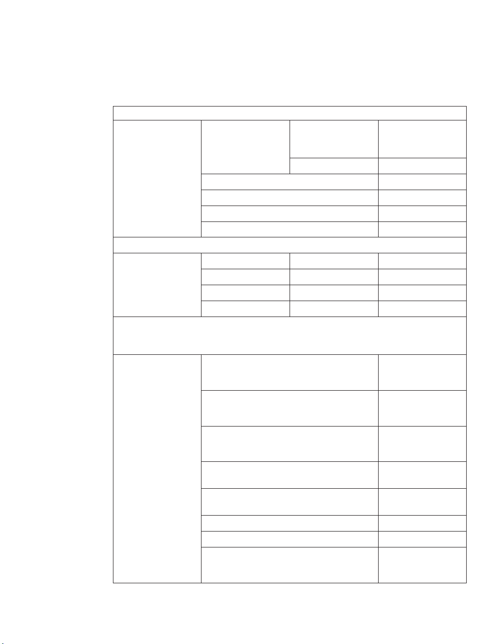
Table 2. EXN1000 electrical requirements
Input voltage 100 to 120V 200 to 240V
Input current
Worst-case Typical
single
PSU/
system
7.2K drives 2.85 1.56/3.12 1.43 0.78/1.56
Worst-case Typical
single
PSU/
system
measured, A
Input power
7.2K drives 284 155/310 283 152/304
measured, W
Thermal
7.2K drives 968 529/1058 964 517.5/1035
dissipation,
BTU/hr
Inrush peak, A 7.2K drives 21 20 12.5 12.0
Input power frequency, Hz 50 to 60
Maximum electrical power 7 A 3.5 A
Note: Worst-case indicates a system running with one PSU and high fan
speed. Typical indicates a system running two PSUs on two circuits.
Checking shipment package contents
Make sure that your shipment package includes the following items, in
addition to the IBM System Storage EXN1000 Storage Expansion Unit Hardware
and Service Guide:
v EXN1000 Installation and Setup Instructions.
v An EXN1000 expansion unit containing the power supplies and SATA disks
you ordered.
v FC-AL cables and power cords, as ordered.
v A rail kit for mounting the EXN1000 in a standard 19–inch rack may also be
included.
Rules for installing EXN1000 expansion units in a rack
You need to observe the following rules and restrictions when installing an
EXN1000 expansion unit in a standard 19-inch (48.26 cm) equipment rack
with mounting rails:
4
Page 35
32-55 kg (70.5-121.2 lbs)
svc00168
DANGER
DANGER
The weight of this part or unit is between 32 and 55 kg (70.5
and 121.2 lb). It takes three persons to safely lift this part or unit. (C010)
Attention: Remove the power supplies and fan units from the chassis before
attempting to lift the system.
v Yo u must work with two other people.
DANGER
EXN1000 expansion unit is extremely heavy. To avoid injuring
The
yourself or damaging the EXN1000 expansion unit, you must work
with at least two other people when you install the EXN1000
expansion unit in the rack.
v Install the expansion unit at the bottom of the rack first.
DANGER
avoid hazardous conditions due to uneven mechanical loading,
To
always install the heaviest devices in the bottom of the rack cabinet.
Always install servers and optional devices starting from the bottom of
the rack cabinet. (R001 part 1 of 2)
For additional rack safety notices, refer to “Rack safety” on page viii.
v When installing EXN1000 expansion units in a rack, do not exceed the
maximum storage limit for your N series storage system.
v Always install the EXN1000 expansion units fully loaded. Do not remove
the disk drives or drive blank covers to reduce the weight.
Guide to the installation process
The following table provides a guide to the EXN1000 expansion unit
installation process.
Refer to the Installation and Setup Instructions for your storage system for
complete installation details.
Chapter 1. Preparing for the installation 5
Page 36

DANGER
people are required to lift the EXN1000 during installation. Do not
Three
remove the disk drives or drive blank covers to reduce the weight.
Table 3. EXN1000 expansion unit installation process
Is the procedure
Stage Procedure
1 Install the N series
storage system in a
freestanding rack.
required?
Only if the EXN1000
expansion unit
installation is part of a
new system
installation.
For instructions, go
to...
Hardware guide for
your N series storage
system, or the
Installation and Setup
Instructions that came
with your N series
storage system.
2 Install the EXN1000
expansion units in the
rack.
Yes, if the EXN1000
expansion unit is an
addition to your
See the EXN1000
Installation and Setup
Instructions.
existing system or if
Attention:
When
installing multiple
your new system was
not shipped in a rack.
storage expansion units
that share a drive loop,
always install them
sequentially as they
will appear in the loop.
3 Connect the EXN1000
expansion unit to the N
series storage system.
Only in the following
scenarios:
v If the EXN1000
expansion unit
installation is part of
a new system
Chapter 2, “Connecting
an EXN1000 expansion
unit,” on page 13, or
the EXN1000
Installation and Setup
Instructions.
installation.
v If the EXN1000
expansion unit is the
first in an additional
loop to your existing
system.
6
Page 37

Table 3. EXN1000 expansion unit installation process (continued)
Stage Procedure
4 Connect the EXN1000
expansion units.
Is the procedure
required?
Only in the following
scenarios:
v If the new system
For instructions, go
to...
See the EXN1000
Installation and Setup
Instructions.
installation has
multiple EXN1000
expansion units.
v If the EXN1000
expansion unit is an
addition to your
existing system.
5 Ground the EXN1000
expansion units and N
series storage system.
Yes. “Grounding EXN1000
expansion units” on
page 15, or the
EXN1000 Installation
and Setup Instructions.
6 Connect the EXN1000
expansion units to a
power source.
Yes. “Connecting the
EXN1000 expansion
unit to a power source”
on page 15
If the system was
shipped in a rack, you
must connect the rack
See the documentation
that shipped with your
cabinet.
to a power source.
7 Configure the system. Yes, if the EXN1000
expansion unit
installation is part of a
new system
See the Data ONTAP
Software Setup Guide for
your version of Data
ONTAP.
installation.
Before you begin your installation
Before you install one or more EXN1000 expansion units in a rack, you need
to understand the following information:
v EXN1000 expansion unit numbering
v Drive addressing
v Speed setting
v Supported disk drives
v Drive bay requirements
Chapter 1. Preparing for the installation 7
Page 38
Attention: Verify that all shelf IDs are correct and sequential in the
individual loop(s). If this system was configured by manufacturing, there are
labels on the outside of the packaging carton and on the side of the expansion
unit chassis to indicate which loop on which node (Filer 1 or 2) that shelf
should be located. Make certain the expansion units are placed and cabled
according to these labels. The filer nodes may also have a label on the
packaging carton and chassis side to clearly distinguish the nodes (Filer 1 and
Filer 2).
EXN1000 expansion unit numbering
Each EXN1000 expansion unit in a loop must have a unique ID. A valid shelf
ID is from 1 through 7. ID 1 is used for the first EXN1000 in a new loop, or if
the filer also contains disks, then ID 2 is used for the EXN1000 closest to the
N series storage system controller (which uses ID 1). Shelf IDs for additional
expansion units are incremented sequentially from the number of the first
expansion unit (either 1 or 2).
Each EXN1000 expansion unit shipped with an N series storage system has its
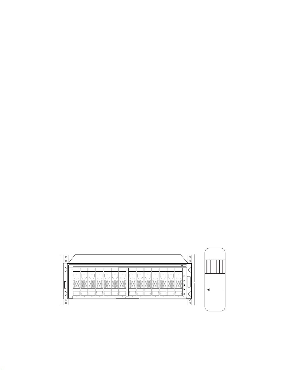
assigned ID already set on its back panel and has a shelf ID label already
placed on its front bezel.
You must ensure that the EXN1000 expansion unit has the correct shelf ID
number on the label. If you change the shelf ID of the expansion unit by
changing the ID switch at the rear of the unit, replace the shelf ID label to
match the new shelf ID for the unit.
Note: Additional shelf ID labels are supplied with your unit.
The shelf ID label is on the right side of the unit, as shown in the following
illustration.
Shelf 1
Drive Bays
013
Loop ID
29 - 16
Figure 1. Shelf ID label
7
8910111213 3 2 1 0
5
4
6
8
Page 39

IBM sets the disk shelf IDs at the factory on configured systems, using an ID
switch on the back panel. If you order additional EXN1000 expansion units,
you must set the disk shelf ID and apply the correct labels provided with the
EXN1000.
Note: If you enter a shelf ID that is not from 1 through 7, the drive addresses
default to those of a shelf with the ID switch set to 7 even though the
Shelf ID indicator in the front operation panel displays a dash (-).
The example in the following illustration shows an EXN1000 expansion unit
with the disk shelf ID set to 2.
Shelf ID - close-up view
Mute button
2
Out port activity LED
Figure 2. EXN1000 shelf ID
Drive addressing
In addition to identifying the disk shelf ID and the direction of the drive bays,
the ID label on the right side of the EXN1000 expansion unit includes the
drive address. The drive address identifies the disks in the EXN1000
expansion unit. The last sheet of the quick reference cards that come with
your EXN1000 expansion unit shows the seven disk shelf IDs and their
corresponding drive addresses.
Shelf ID
Out port
In port activity LED
2
In port
Ready LED
Fault LED
Chapter 1. Preparing for the installation 9
Page 40
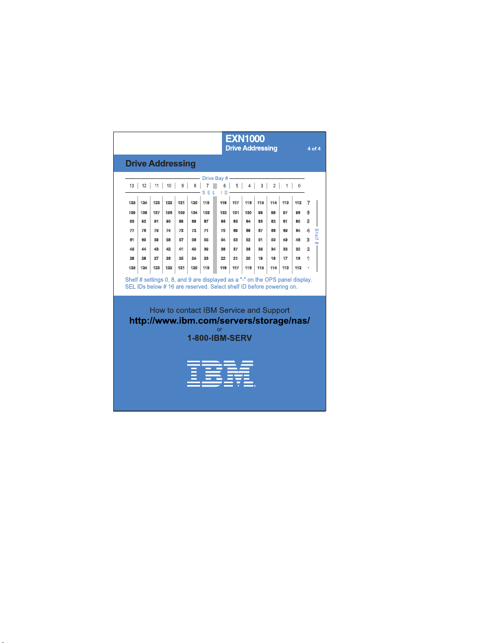
Note: For AT-FCX module A, drive addressing is in descending order, and for
AT-FCX module B, drive addressing is ascending order. AT-FCX A is
the top controller module in the EXN1000. AT-FCX B is the bottom
controller module.
10
Figure 3. EXN1000 disk shelf IDs and drive addressing
Speed setting
Make sure that all expansion unit speed switches are set to the correct
position for your application.
v If connecting to an N3700 storage system, the speed switch must be set to
the 1Gb position.
v If connecting to any other N series storage system, the speed switch must
be set to the 2Gb position.
The speed setting switch is located on the circuit board inside the
Note:
AT-FCX module. In order to set or adjust the speed setting, you must
remove the AT-FCX module. See “Replacing an AT-FCX module” on
page 35.
Page 41

The speed setting must be set before you power on the expansion unit.
Figure 4. EXN1000 speed setting switch
Supported disk drives
For the types of disks the EXN1000 expansion unit supports, visit the
following Web site:
www.ibm.com/storage/nas/
Note: You should not mix different drive types in the same expansion unit.
Drive bay requirements
For enclosure services monitoring to work, drive bays 0 and 1 must contain a
disk. In addition, the EXN1000 expansion unit must be populated with at least
5 hard disk drives to ensure proper operation.
Attention: All drive bays in the expansion must contain either a hard disk
drive or a drive blank cover to maintain proper air flow and cooling.
The 14 drive bays in the EXN1000 expansion unit are numbered 0 through 13
from right to left, as shown in Figure 1 on page 8. Hard disk drives should be
populated in adjacent drive bays in the expansion unit in this sequence,
beginning with drive bay 0.
The N series storage system uses the enclosure services monitoring method to
monitor environmental conditions of the EXN1000 expansion unit. Enclosure
services conditions are communicated to the N series storage system through
the AT-FCX module.
The following table describes the three stages of enclosure services
monitoring.
Chapter 1. Preparing for the installation 11
Page 42

Table 4. Stages of enclosure services monitoring
Stage Device What it does...
1 N series storage system Uses a subset of SCSI-3
commands to monitor the
EXN1000 expansion unit
for data related to disk
presence, temperature,
power supply units, and
fan status.
2 N series storage system Sends the commands
through its Fibre Channel
interface to the AT-FCX
I/O module on the
EXN1000 expansion unit.
3 AT-FCX module Collects the requested data
and sends it to the storage
appliance.
12
Page 43

Chapter 2. Connecting an EXN1000 expansion unit
This chapter describes how to connect a single EXN1000 expansion unit or a
loop of EXN1000 expansion units to a supported N series storage system or to
other expansion units. This chapter also describes how to ground your system
and how to connect your system to power.
This chapter discusses the following topics:
v “Handling fiber-optic cables”
v “Connecting EXN1000 expansion units” on page 14
v “Grounding EXN1000 expansion units” on page 15
v “Connecting the EXN1000 expansion unit to a power source” on page 15
v “Hot-adding an EXN1000 expansion unit to an existing loop” on page 15
Handling fiber-optic cables
Before you use fiber-optic cables, read the following precautions.
Attention: To avoid damage to the fiber-optic cables, follow these guidelines:
v Do not route the cable along a folding cable-management arm.
v When attaching to a device on slide rails, leave enough slack in the cable so
that it does not bend to a radius of less than 38 mm (1.5 in.) when extended
or become pinched when retracted.
v Route the cable away from places where it can be snagged by other devices
in the rack cabinet.
v Do not overtighten the cable straps or bend the cables to a radius of less
than 38 mm (1.5 in.).
v Do not put excess weight on the cable at the connection point. Be sure that
the cable is well supported.
CAUTION:
Data processing environments can contain equipment transmitting on
system links with laser modules that operate at greater than Class 1
power levels. For this reason, never look into the end of an optical
fiber cable or open receptacle. (C027)
© Copyright IBM Corp. 2005, 2007 13
Page 44

Connecting EXN1000 expansion units
This section describes the requirements for connecting the EXN1000 expansion
unit to N series storage systems and other expansion units. For detailed
instructions about how to install and connect one or more EXN1000 expansion
units in a rack, refer to the Installation and Setup Instructions.
v IBM strongly recommends using optical (fibre channel) cabling whenever
possible.
v Refer to the IBM System Storage N series Introduction and Planning Guide for
details about the maximum number of drive loops, maximum number of
expansion units or hard disk drives per loop, maximum total storage
capacity, and maximum total number of hard disk drives for configurations
using your N series storage system. (For example, you can connect a
maximum of one loop of three fully populated expansion units to an
N3700.)
v Multipath looping is recommended for all configurations to provide
additional redundancy. This includes single or dual controller and single or
multiple EXN1000 expansion units.
v Do not mix Fibre Channel EXN2000 or EXN4000 and SATA EXN1000
expansion units in the same loop.
EXN1000 expansion unit cabling requirements
You must meet the cabling requirements discussed in the following sections
when connecting the EXN1000 AT-FCX module to an N series storage system
or to other expansion units.
14
For the latest information on cabling requirements, see the Installation and
Setup Instructions and the Hardware and Service Guide for your storage system.
Connecting the expansion unit directly to the N series storage system
When connecting the EXN1000 to an N series storage system, you must use
appropriate cables and connectors according to the following guidelines:
v For direct connections to N3700 storage systems with system serial
numbers between 13-00032 and 13-01000 (in general, these are N3700
systems shipped prior to January 31, 2006): Use a NAS-to-EXP fibre
channel copper cable (#2020 or 2022). For attachment to an N3700 Model
A10, one NAS-to-EXP fibre channel copper cable is required. For attachment
to an N3700 Model A20, two NAS-to-EXP fibre channel copper cables are
required.
v For direct connections to N3700 storage systems with system serial
numbers 13-01001 or higher (in general, these are N3700 systems shipped
after January 31, 2006): Use an LC-to-LC fibre channel optical cable and 2
SFPs for attachment to an N3700 Model A10. Use 2 LC-to-LC fibre channel
optical cables and 4 SFPs for attachment to an N3700 Model A20.
Page 45

v For direct connections to all other N series storage systems: Use an
LC-to-LC fibre channel optical cable and one SFP.
Connecting
the expansion unit to other expansion units
When connecting the EXN1000 to other expansion units, IBM strongly
recommends using LC-to-LC fibre channel optical cables. You must use 2 SFPs
per LC-to-LC fibre channel optical cable.
Note: SFP-to-SFP fibre channel copper cables may also be used for
connections (to a maximum of three meters) between expansion units.
Grounding EXN1000 expansion units
For proper grounding, you must daisy-chain the EXN1000 expansion units
together with the provided braided copper cables and screws. If possible, you
should ground the N series storage system to the EXN1000.
Each EXN1000 expansion unit is shipped with a 0.25m (~6 inch) braided
copper cable and an M5 x 0.5 inch Phillips head screw. The copper cable has a
hole on each end for grounding shelf-to-shelf.
For detailed instructions about how to ground connected EXN1000 expansion
units in a rack, refer to the Installation and Setup Instructions for your storage
system.
Connecting the EXN1000 expansion unit to a power source
The EXN1000 expansion unit is shipped with two power supplies, installed in
bay PSU1 and bay PSU2, respectively, and an AC power cord for each power
supply. You must have separate circuit breakers for each power supply.
For detailed instructions about how to connect EXN1000 expansion units to a
power source, refer to the EXN1000 Installation and Setup Instructions.
Hot-adding an EXN1000 expansion unit to an existing loop
This section provides information about how to hot-add an EXN1000
expansion unit to an existing loop. It also tabulates the error messages that
appear on your N series storage system console if the attempt at hot-adding
was unsuccessful.
Note: The hot-added EXN1000 expansion unit must have new drives that will
be used as spares only.
Chapter 2. Connecting an EXN1000 expansion unit 15
Page 46

Attention: It is recommended that you stop all I/O processes before
hot-adding an EXN1000 to an existing loop. Perform a hot-add only during
off-peak times.
To hot-add an EXN1000 expansion unit to an existing loop, complete the
following steps:
1. Put on the antistatic ESD strap and grounding leash.
2. Verify that you received the disk shelf ID labels.
3. Install the new EXN1000 expansion unit in the rack, cable and ground the
EXN1000, and connect the power cables to the EXN1000, as described in
the Installation and Setup Instructions you received with your N series
product.
CAUTION:
Do not turn on the power to the EXN1000 expansion unit yet.
After you have completed the installation steps described in the Installation
and Setup Instructions, continue with Step 4.
4. Verify that all the cables are securely fastened.
CAUTION:
Poorly secured cables cause the N series storage system to panic over an
open loop.
5. If you have not done so, give the EXN1000 expansion unit a unique disk
shelf ID. It is recommended that you choose a number which is one higher
than the previous shelf (or ID 1 if this is the first EXN1000 in the loop).
a. Press the small buttons on the switch on the rear of the EXN1000
expansion unit, using the + button to raise the number and the button to lower the number to a valid ID from 1 through 7. Refer to
Figure 2 on page 9 for an illustration.
16
Only use disk shelf ID 7 if it is the last ID available. If you
Note:
change a disk shelf ID, you must power-cycle the EXN1000
expansion unit for the new ID to take effect. The disk shelf ID
display on the front of the EXN1000 expansion unit blinks until
you power-cycle the EXN1000 expansion unit.
b. Verify that the disk shelf ID is not being used in the loop by entering
the following command at the console:
fcstat device_map adaptername
c. Select the correct matching shelf ID label, reference Figure 1 on page 8,
and attach it to the right flange of the new EXN1000 expansion unit.
CAUTION:
An invalid disk shelf ID causes the N series storage system to panic.
6. Turn on the power to the EXN1000 expansion unit. Yo u must wait 30
seconds for the shelf electronics to finish initializing.
Page 47

7. In 60 seconds, the N series storage system recognizes the hot-added
EXN1000 expansion unit.
Error messages
The following error messages appear on your N series storage system console
if your attempt at hot-adding the EXN1000 expansion unit is unsuccessful.
Table 5. N series storage system console error messages
Error message Explanation
Open loop panic One of two reasons cause this error message to appear:
v The shelf-to-shelf cable between the now second-to-last unit
and the newly added EXN1000 expansion unit is defective or
is not securely fastened.
v The speed of the newly added EXN1000 expansion unit is
incorrectly set.
Soft address
panic
One of two reasons cause this error message to appear:
v There is an invalid disk shelf ID.
v The power was turned on before the disk shelf ID was
changed and the EXN1000 expansion unit was not
power-cycled after the disk shelf ID was changed.
Chapter 2. Connecting an EXN1000 expansion unit 17
Page 48

18
Page 49

Chapter 3. Monitoring the EXN1000 expansion unit
This chapter describes how to monitor the EXN1000 expansion unit from the
error messages displayed on the console that is connected to the N series
storage system and identifies the location of the various LEDs on the
EXN1000 expansion unit.
Note: The quick reference cards in the slide-out tray at the base of the
EXN1000 expansion unit describe the functions of each LED on the
EXN1000 expansion unit and the suggested course of action.
This chapter discusses the following topics:
v “Monitoring the front operation panel”
v “Monitoring the AT-FCX modules” on page 22
v “Monitoring the power supply” on page 24
v “Monitoring the ATA disk” on page 27
Monitoring the front operation panel
The front operation panel has five LEDs and a disk shelf ID display. The
LEDs indicate whether your EXN1000 expansion unit is functioning normally
or there are problems with the hardware. Hardware failure associated with
the front operation panel of the EXN1000 expansion unit can be identified
from the error messages displayed on your N series storage system console.
© Copyright IBM Corp. 2005, 2007 19
Page 50
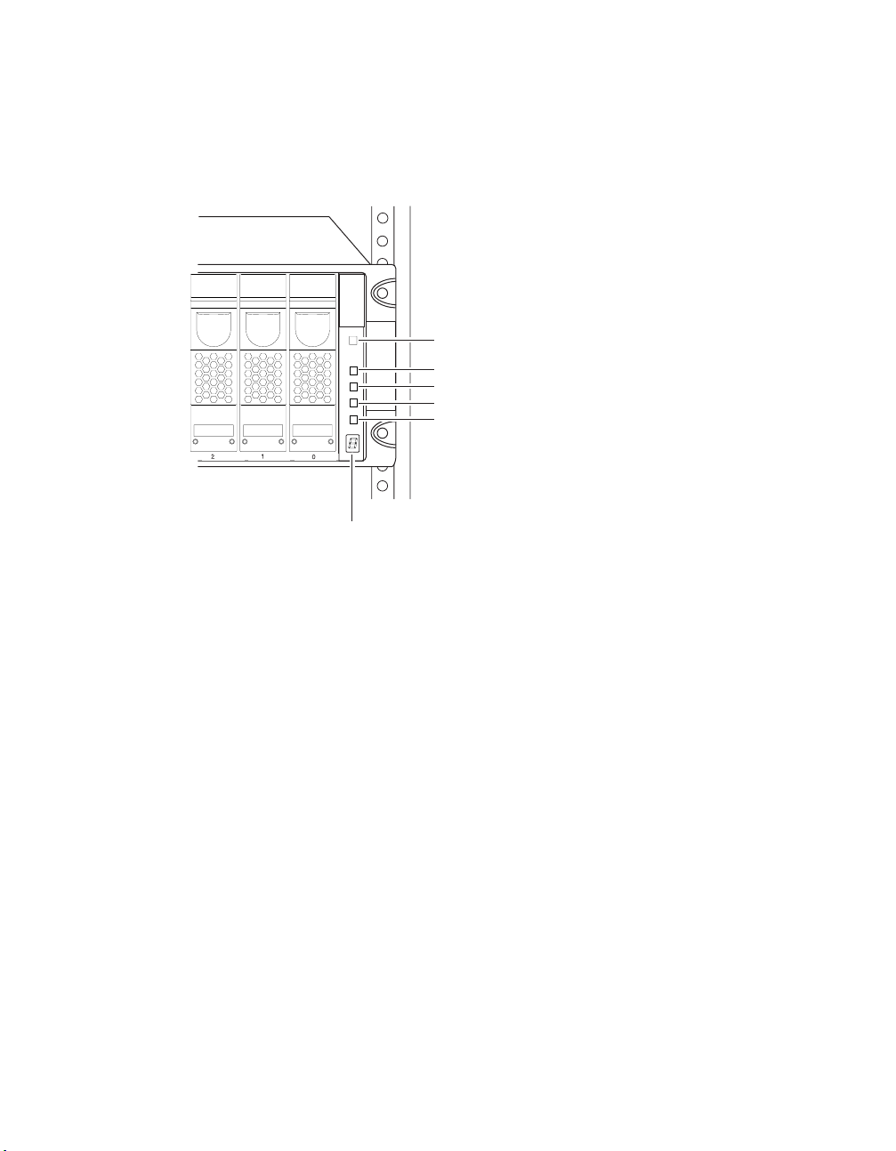
Location of LEDs
The following illustration shows the location of the disk shelf ID display and
the front panel LEDs.
Power
Fault
Loop A
Loop B
System
Disk shelf ID display
Figure 5. Front panel LEDs
Note: The Fault and System LEDs are amber. The other three LEDs are green.
See Figure 6 on page 21 for an illustrated explanation of how the LEDs
function.
Monitoring the disk shelf ID
When you use the switch on the back of the EXN1000 expansion unit to
change the disk shelf ID, the disk shelf ID display on the front panel blinks
until you power-cycle the EXN1000 expansion unit to make the change take
effect.
LED status on the front operation panel
The following illustration is of the first sheet of the quick reference cards that
come with your EXN1000 expansion unit. It shows the normal and fault
conditions that the LEDs indicate and recommends a corrective action.
20
Page 51
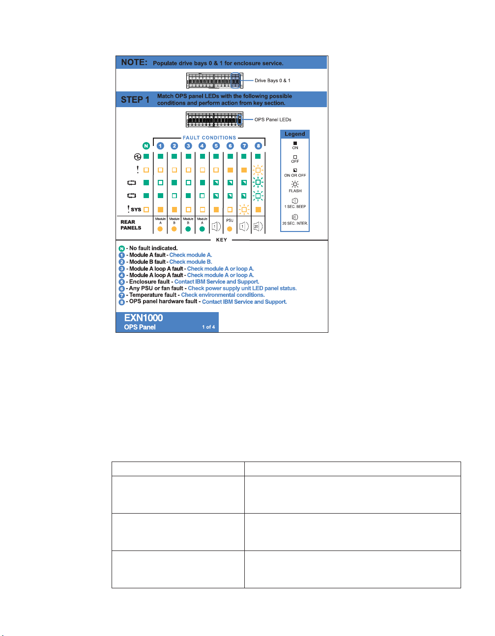
A
B
Figure 6. LED indications of normal and fault conditions
Front operation panel console error messages
The following error messages appear on your N series storage system console
if an SES element on the front operation panel fails. For information about
replacing an EXN1000 expansion unit, see “Removing an EXN1000 expansion
unit” on page 29.
Table 6. N series storage system error messages
Error message Action required
Temperature sensor
Element 1: failed
The temperature sensor on the front operation panel
failed. Contact IBM customer service to replace the
EXN1000 expansion unit.
Alarm
Element 1: failed
The alarm on the front operation panel failed.
Contact IBM customer service to replace the
EXN1000 expansion unit.
Display
Element 1: failed
The display on the front operation panel failed.
Contact IBM customer service to replace the
EXN1000 expansion unit.
Chapter 3. Monitoring the EXN1000 expansion unit 21
Page 52
Monitoring the AT-FCX modules
The AT-FCX module has four LEDs. The LEDs indicate whether the module is
functioning normally, or whether there are any problems with the hardware.
You can also identify any hardware failure associated with the module from
the error messages displayed on your N series storage system console.
This section also describes the different types of messages that appear on the
N series storage system console in response to a command monitoring the
AT-FCX.
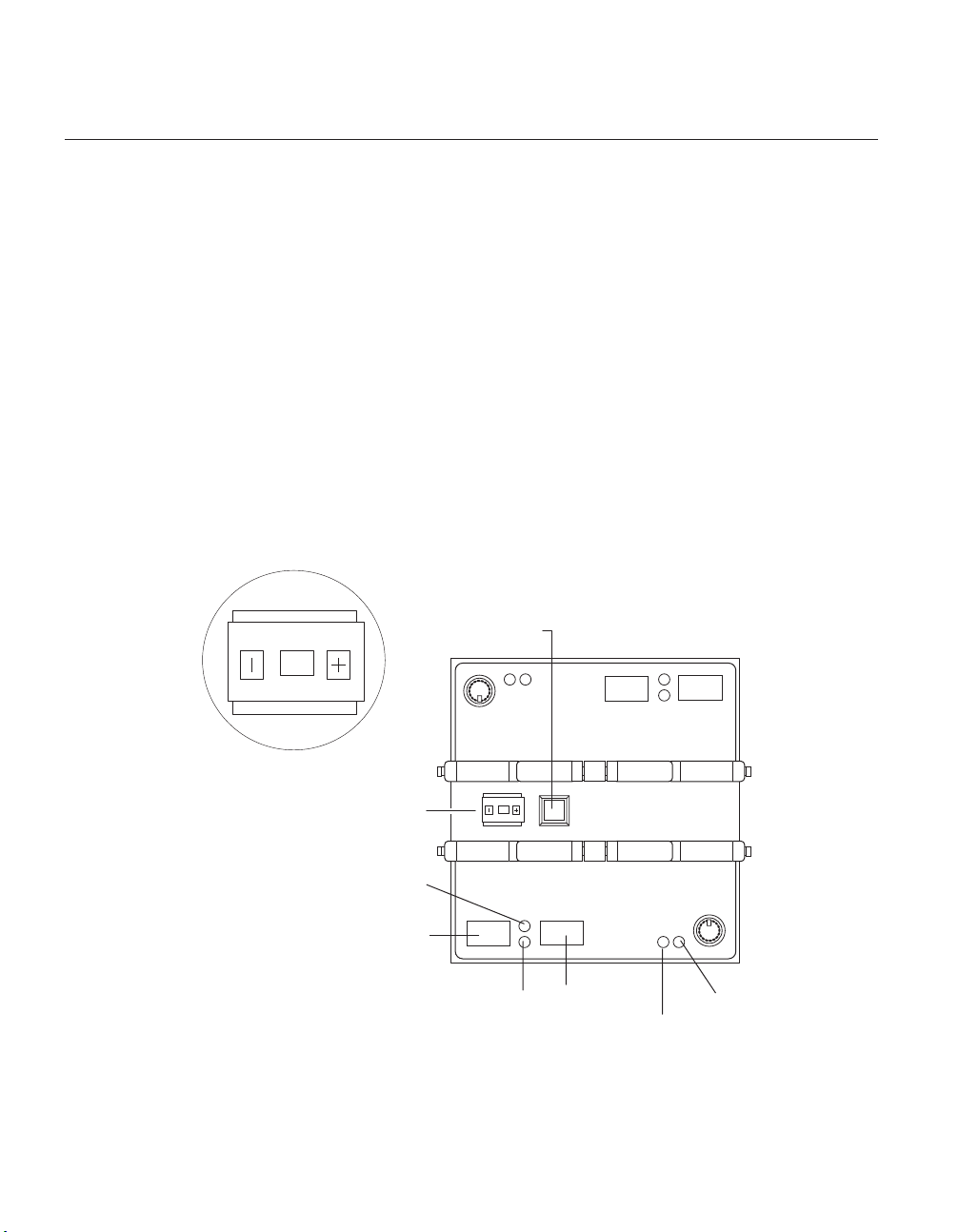
Location of the module LEDs
The modules are in the middle of the back of the EXN1000 expansion unit.
The following illustration shows the location of the LEDs for an AT-FCX. See
“LED status on the AT-FCX” on page 23 for an illustrated explanation of the
LED functions.
Shelf ID - close-up view
22
Mute button
2
Shelf ID
Out port activity LED
Out port
In port activity LED
Figure 7. Location of the LEDs for an AT-FCX
2
In port
Ready LED
Fault LED
Page 53
Note: Because module A on the EXN1000 expansion unit is inverted, the
location of the module A LEDs is the inverse of what is shown in the
preceding illustrations.
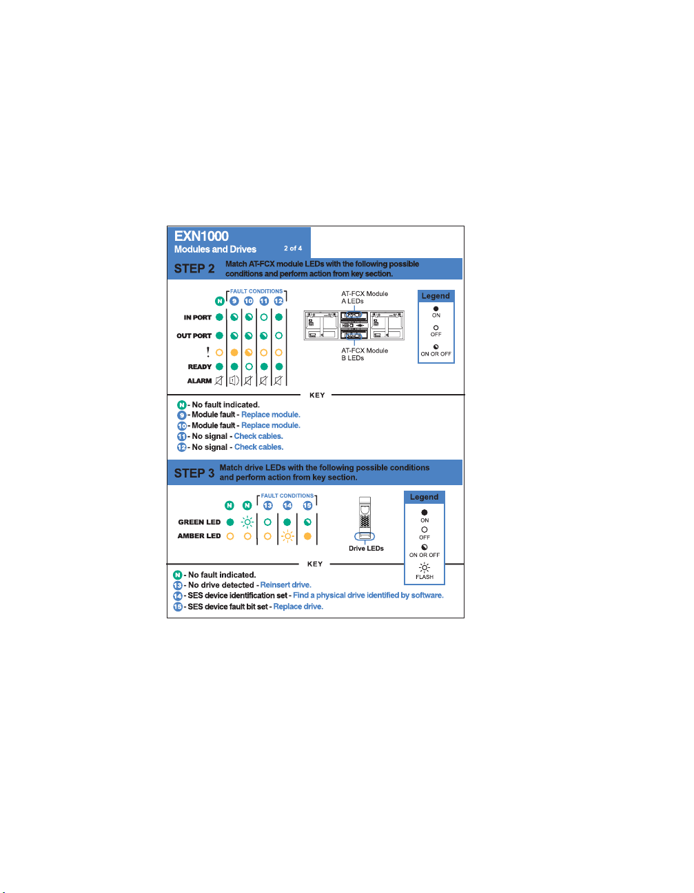
LED status on the AT-FCX
The following illustration is of the second sheet of the quick reference cards
that come with your EXN1000 expansion unit.
Figure 8. EXN1000 rear panel quick reference card
Note: The rest of the second sheet of the quick reference card identifies the
LED status conditions for the ATA disks.
AT-FCX console error messages
The following error messages appear on your N series storage system console
if an SES element on the AT-FCX fails. For information about replacing the
AT-FCX, see “Replacing an AT-FCX module” on page 35.
Chapter 3. Monitoring the EXN1000 expansion unit 23
Page 54

Table 7. AT-FCX console error messages
Error message Action required
Temperature sensor 2:
Contact IBM customer service to replace the module.
failed
Temperature sensor 3:
failed
SES electronics Element 1:
component is from a
This configuration is unsupported. Contact IBM
customer service to replace the module.
different product family
SES electronics
Contact IBM customer service.
Element 1: failed
SES electronics
Element 2: failed
Temperature sensor 2: not
The AT-FCX module on the expansion unit failed.
Contact IBM customer service to replace the module.
Contact IBM customer service.
installed or failed
Environmental sensor 3: not
installed or failed
SES electronics Element 1:
not installed or failed
Vendor-specific Element 1:
not installed or failed
SES electronics
Element 2: not
installed or failed
Communication with the temperature sensor on the
AT-FCX module failed. Replace the AT-FCX module as
described in “Hot-swapping a module” on page 37.
Vendor-specific
Element 2: not
installed or failed
Monitoring the power supply
The power supply has four LEDs. The LEDs indicate whether the power
supply or the integrated fan module is functioning normally or there are
problems with the hardware. You can also identify any hardware failure
associated with the power supplies from the error messages displayed on
your N series storage system console.
The following illustration is of the third sheet of the quick reference cards that
comes with your EXN1000 expansion unit.
24
Page 55

ON
OFF
Figure 9. Third sheet of the quick reference cards
Location of LEDs
Each power supply, which contains four LEDs, is encased in a device carrier
and housed at the rear of the EXN1000 expansion unit. The following
illustration shows the location of the power supply LEDs.
Chapter 3. Monitoring the EXN1000 expansion unit 25
Page 56
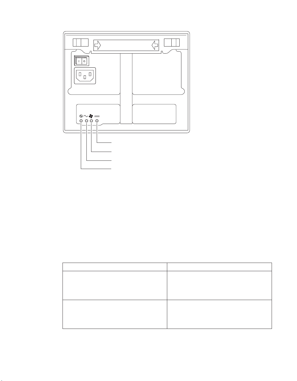
Power
Fan LED
AC LED
PSU status normal
Figure 10. Location of power supply LEDs
Note: The PSU status LED is green. The other three LEDs are amber. See
Figure 9 on page 25 for an illustrated explanation of how the LEDs
function.
Power supply console error messages
The following error messages appear on your N series storage system console
if an SES element on the power supply fails. For information about replacing
the power supply, see “Replacing a power supply in an EXN1000 expansion
unit” on page 33.
Table 8. Power supply console error messages
Error message Action required
Power supply
Element 1: failed
The power supply unit on the left at the
back of the EXN1000 expansion unit
failed. Contact IBM customer service to
replace the power supply.
Power supply
Element 2: failed
The power supply unit on the right at the
back of the EXN1000 expansion unit
failed. Contact IBM customer service to
replace the power supply.
26
Page 57
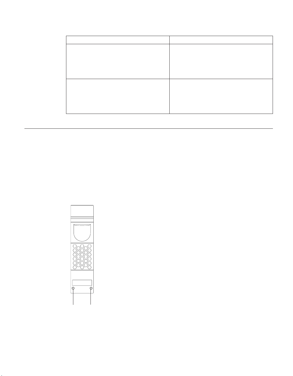
Table 8. Power supply console error messages (continued)
Error message Action required
Cooling element
Element 1: failed
Cooling element
Element 2: failed
Monitoring the ATA disk
The ATA disk has two LEDs. The LEDs indicate whether the disk is
functioning normally or there are problems with the hardware. See Figure 8
on page 23 for an illustrated explanation of how the LEDs function.
Location of LEDs
The following illustration shows the ATA disk, which has two LED indicators
on the front.
The integrated fan module in the power
supply unit on the left at the back of the
EXN1000 expansion unit failed. Contact
IBM customer service to replace the
power supply.
The integrated fan module in the power
supply unit on the right at the back of the
EXN1000 expansion unit failed. Contact
IBM customer service to replace the
power supply.
Amber
Figure 11 . ATA disk
Green
Note: Drives that are idle perform a media scan in the background resulting
in the LEDs pulsing every half-second.
Chapter 3. Monitoring the EXN1000 expansion unit 27
Page 58

28
Page 59

Chapter 4. Replacing EXN1000 expansion unit devices
This chapter describes how to replace EXN1000 expansion units in a rack,
disks in an EXN1000 expansion unit, and other devices, in the following
sections:
v “Removing an EXN1000 expansion unit”
v “Replacing a disk in an EXN1000 expansion unit” on page 32
v “Replacing a power supply in an EXN1000 expansion unit” on page 33
v “Replacing an AT-FCX module” on page 35
Attention: Return failed parts to IBM. Contact IBM Service and Support at
1-800-IBM-SERV (1-800-426-7378) for more information on the return
procedure.
Removing an EXN1000 expansion unit
This section discusses how to disconnect an EXN1000 expansion unit from an
N series storage system and how to remove an EXN1000 expansion unit from
a daisy-chain configuration. It does not discuss how to install an EXN1000
expansion unit or how to hot-add an EXN1000 expansion unit. For
information about installing an EXN1000 expansion unit in a rack, see “Guide
to the installation process” on page 5. For information about hot-adding a
disk-shelf, see “Hot-adding an EXN1000 expansion unit to an existing loop”
on page 15.
CAUTION:
Hot removal or hot-swapping of an EXN1000 expansion unit is not
supported.
For detailed information about removing an EXN1000 expansion unit from a
rack, see the following topics:
v “Removing an EXN1000 expansion unit from a single EXN1000 expansion
unit configuration” on page 30
v “Removing an EXN1000 expansion unit from a loop” on page 31
© Copyright IBM Corp. 2005, 2007 29
Page 60

Removing an EXN1000 expansion unit from a single EXN1000 expansion unit configuration
To remove an EXN1000 expansion unit from a single EXN1000 expansion unit
configuration, complete the following steps:
1. Shut down the N series storage system by entering the following
command at the console:
halt
CAUTION:
Disable the cluster first and then use the halt command to shut down
all controllers to which the loop is connected.
2. Turn off the power switches on the EXN1000 expansion unit.
3. Put on the antistatic ESD strap and grounding leash.
4. Disconnect the two EXN1000 expansion unit power cords from the
EXN1000 expansion unit.
5. Disconnect the Fibre Channel cable connecting the EXN1000 expansion
unit and N series storage system.
6. Use a flat-blade screwdriver to remove the tie-down screws securing the
rear of the EXN1000 to the rack. Use a 7mm nut driver to remove the
screws securing the front of the EXN1000 to the rack.
30
32-55 kg (70.5-121.2 lbs)
svc00168
DANGER
DANGER
The weight of this part or unit is between 32 and 55 kg (70.5
and 121.2 lb). It takes three persons to safely lift this part or unit. (C010)
Attention: Remove the power supplies and fan units from the chassis before
attempting to lift the system.
With the help of at least two people, remove the EXN1000 expansion unit
7.
from the rack.
Page 61

DANGER
EXN1000 expansion unit is extremely heavy. To avoid injuring
The
yourself or damaging the EXN1000 expansion unit, you must work
with at least two other people when you install the EXN1000
expansion unit in the rack.
Removing an EXN1000 expansion unit from a loop
To remove an EXN1000 expansion unit from a loop of EXN1000 expansion
units, complete the following steps:
1. Shut down the N series storage system by entering the following
command at the console:
halt
CAUTION:
Disable the cluster first and then use the halt command to shut down
all controllers to which the loop is connected.
2. Turn off the power switches on the EXN1000 expansion unit.
3. Put on the antistatic ESD strap and grounding leash.
4. Disconnect the two EXN1000 expansion unit power cords from the
EXN1000 expansion unit that you are going to remove.
5. Disconnect the Fibre Channel cables connecting the EXN1000 expansion
unit to the other EXN1000 expansion units or the N series storage system.
6. Use a flat-blade screwdriver to remove the tie-down screws securing the
rear of the EXN1000 to the rack. Use a 7mm nut driver to remove the
screws securing the front of the EXN1000 to the rack.
32-55 kg (70.5-121.2 lbs)
svc00168
CAUTION:
Use safe practices when lifting.
With the help of at least two people, remove the EXN1000 expansion unit
7.
from the rack.
Chapter 4. Replacing EXN1000 expansion unit devices 31
Page 62

DANGER
EXN1000 expansion unit is very heavy when fully loaded and
The
requires at least three people to remove it.
8. Do one of the following:
v If you are not installing a replacement EXN1000 expansion unit, then
reestablish the loop by connecting the disconnected EXN1000 expansion
units or by connecting the unconnected EXN1000 expansion unit to the
N series storage system.
v If you are installing a replacement EXN1000 expansion unit, then see
“Guide to the installation process” on page 5.
Replacing a disk in an EXN1000 expansion unit
You can replace a disk in an EXN1000 expansion unit for any reason.
However, the most common reason is disk failure. If a disk fails, the N series
storage system logs a warning message to the system console indicating
which disk on which loop failed.
In addition, an EXN1000 expansion unit with an AT-FCX module identifies
any one of the following situations as disk failure:
v A disk is bypassed.
v The filer system boots with the presence of bypassed disks.
v The filer system detects an eminent threshold bypass.
32
Preparing to replace a disk
Before you replace a disk in an EXN1000 expansion unit, you must first check
the EXN1000 expansion unit to ensure that after you remove the disk you still
have enough disks installed to meet the enclosure services requirements. For
information about these requirements, see “Drive bay requirements” on page
11.
Replacing a disk in an EXN1000 expansion unit consists of the following
procedures:
v “Removing a disk”
v “Installing a disk” on page 33
Removing a disk
To remove a disk, complete the following steps:
1. Do one of the following:
v If you are removing a disk that is a member of a volume, then enter:
disk fail disk_name
v If you are removing a disk that is a spare disk, then enter:
Page 63

disk remove disk_name
Note: To display the status of the disk, enter the following command:
disk show -b
Note: Either command causes the amber fault LED on the disk to
illuminate. For more information about LEDs, see “Monitoring
the ATA disk” on page 27.
For more information about disk commands, see the System
Administrator’s Guide.
2. Put on the antistatic ESD strap and grounding leash.
3. To remove the disk, press down on its release mechanism with one hand
while grasping the top flange of the EXN1000 expansion unit with the
other hand.
4. Gently slide the disk until it disengages. Wait 30 seconds for the disk to
stop spinning; then continue removing the disk from the chassis.
CAUTION:
When removing a disk, always use two hands to support its weight.
Installing a disk
To install a disk in an EXN1000 expansion unit, complete the following steps:
1. Put on the antistatic ESD strap and grounding leash.
2. Orient the device carrier so that the release mechanism is at the top.
3. Insert the device carrier into the guide slot in the EXN1000 expansion unit
and firmly push it in until it engages the backplane and you see the
release mechanism click into place.
If the device carrier does not fully seat in the drive bay, you may be
Note:
trying to install an unsupported disk drive in the EXN1000
expansion unit.
CAUTION:
Do not slam the device carrier into place.
4. Make sure that disks are installed in drive bays 0 and 1 for Enclosure
Services to work.
Replacing a power supply in an EXN1000 expansion unit
Replacing a power supply in an EXN1000 expansion unit consists of the
following procedures:
v “Removing a power supply” on page 34
v “Installing a power supply” on page 35
Chapter 4. Replacing EXN1000 expansion unit devices 33
Page 64

Rules for replacing power supplies
When replacing a power supply on your EXN1000 expansion unit, observe the
following rules:
v Yo u do not need to turn off the power to the expansion unit when you
replace one power supply, only the power supply that is being replaced.
v If you are replacing both power supplies in the same EXN1000 expansion
unit, replace them one at a time to avoid powering down the EXN1000
expansion unit.
v Although a single fan failure in one of the power supplies is not a critical
event, it is recommended that you install a new power supply when one of
the two fans in either power supply stops working.
v When hot-swapping power supplies, remove and install the power supplies
within two minutes.
Attention: Your EXN1000 can run with one power supply removed for a
maximum of two minutes. The airflow through your EXN1000 is degraded
when only one power supply is present and operating. Therefore, if the power
supplies are not replaced within two minutes, the system halts and no data is
accessible.
v Have the replacement power supply close by and ready to install before
removing the old one.
34
CAUTION:
Never remove the cover on a power supply fan unit. There are no
serviceable parts inside these components. If you suspect a problem with
one of these parts, contact a service technician.
Removing a power supply
To remove a power supply, complete the following steps:
1. Put on the antistatic ESD strap and grounding leash.
2. Turn off the switch on the power supply that you are replacing.
3. Lift up the clip lock and unplug the power cord from the N series storage
system power supply.
4. Using your thumb and index finger, press the cam mechanism levers
toward each other to release the power supply handle. The following
figure shows how to press the levers on the cam mechanism and release
the power supply handle.
Page 65
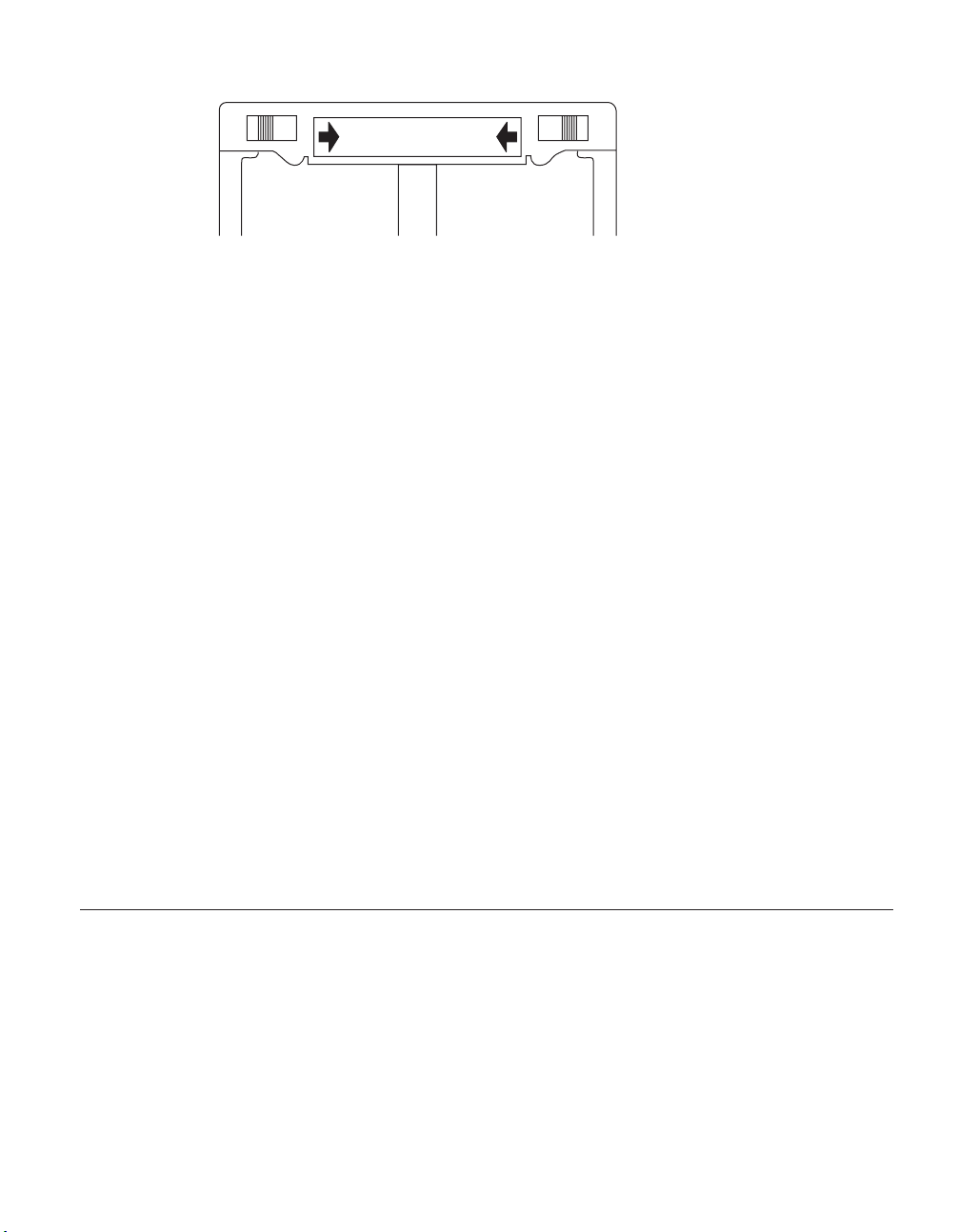
OPEN OPEN
Figure 12. Cam mechanism
5. Use the handle to pull the power supply out of the EXN1000 expansion
unit.
CAUTION:
When removing a power supply, always use two hands to support its
weight.
Installing a power supply
To install a power supply in an EXN1000 expansion unit, complete the
following steps:
CAUTION:
Do not use excessive force when sliding the power supply into the EXN1000
expansion unit. You can damage the connector.
1. Put on the antistatic ESD strap and grounding leash.
2. Slide the power supply in the power supply bay until you hear the power
supply connect with the connector inside the EXN1000 expansion unit
chassis.
3. Raise the handle and push it into place.
4. Using your thumb and index finger, press the cam mechanism levers
toward each other to engage the power supply into place.
5. Plug the power cord into the power receptacle and fasten it with the
clamp.
6. Plug the other end of the power cord into a grounded AC power source.
7. Turn on the power switch.
Replacing an AT-FCX module
The AT-FCX module in an EXN1000 expansion unit includes a SCSI-3
Enclosure Services Processor. It maintains the integrity of the loop when disks
are swapped and provides signal retiming for enhanced loop stability. There
are two AT-FCX modules in the middle of the rear of the EXN1000 expansion
unit, one for Channel A and one for Channel B.
Note: The Input and Output ports on module A on the EXN1000 expansion
unit are inverted from module B.
Chapter 4. Replacing EXN1000 expansion unit devices 35
Page 66

Connectors in an AT-FCX
The AT-FCX module has the following connectors:
Input Provides the interface between the EXN1000 expansion unit and the N
series storage system.
Output
Provides the interface between two EXN1000 expansion units to create
a loop of daisy-chained EXN1000 expansion units.
For detailed information
This section provides information about the following topics:
v “Removing a module”
v “Installing a module”
v “Hot-swapping a module” on page 37
Removing a module
To remove a module that is connected to the Fibre Channel loop, complete the
following steps:
1. Put on the antistatic ESD strap and grounding leash.
2. Shut down the N series storage system by entering the following
command at the console:
halt
36
CAUTION:
Disable the cluster first and then use the halt command to shut down
all controllers to which the loop is connected.
3. Disconnect the AT-FCX module from the Fibre Channel cabling. If you are
using optical cables, remove the associated SFPs from the input and
output ports of the AT-FCX module.
4. Using the thumb and index finger of both hands, press the levers on the
cam mechanism on the module to release it.
5. Pull the module out of the EXN1000 expansion unit.
6. Go to “Installing a module.”
Installing a module
To install a module into the EXN1000 expansion unit, complete the following
steps:
CAUTION:
Observe the “EXN1000 expansion unit cabling requirements” on page 14.
1. Put on the antistatic ESD strap and grounding leash.
2. Verify that the speed setting for the AT-FCX module meets the
requirements for your N series storage system. See “Speed setting” on
page 10.
Page 67

3. Push apart the levers on the cam mechanism and slide the module into the
slot at the rear of the EXN1000 expansion unit, then push the levers of the
cam mechanism into place.
CAUTION:
Do not use excessive force when sliding the module into the EXN1000
unit; you might damage the connector.
4. If you are using optical cables, insert SFPs into the input and output ports
of the AT-FCX module.
5. Reconnect the Fibre Channel cabling.
6. Turn on the power to the EXN1000 expansion units.
7. Reboot the N series storage system.
Hot-swapping a module
The assumptions about this procedure are that AT-FCX modules on the
EXN1000 expansion unit have multipath connections to an N series storage
system.
CAUTION:
If you attempt to hot-swap the AT-FCX on an EXN1000 expansion unit that
does not have multipath connections, you lose all access to the drives on
this EXN1000 expansion unit as well as those below it.
To hot-swap a module, complete the following steps:
Note: To hot-swap a module on an EXN1000 expansion unit in a cluster, see
the cluster guide for your filer.
1. Put on the antistatic ESD strap and grounding leash.
2. From the console of the N series storage system, enter the following
command to disable the loop in which the failed module is a connection:
storage disable adapter adaptername
3. Disconnect the module that you are removing from the Fibre Channel
cabling.
4. Using the thumb and index finger of both hands, press the levers on the
cam mechanism on the module to release it and pull it out of the EXN1000
expansion unit.
5. If you are using optical cables, remove the SFPs from the input and output
ports of the AT-FCX module you have removed. Plug the SFPs into the
input and output ports of the replacement AT-FCX.
6. Verify that the speed setting for the replacement AT-FCX module meets the
requirements for your N series storage system. See “Speed setting” on
page 10.
7. Slide the replacement module into the slot at the rear of the EXN1000
expansion unit and push the levers of the cam into place.
Chapter 4. Replacing EXN1000 expansion unit devices 37
Page 68

CAUTION:
Do not use excessive force when sliding the AT-FCX into the EXN1000
unit; you might damage the connector.
8. Reconnect the Fibre Channel cabling.
9. From the console of the filer, enter the following command to enable the
loop in which the replacement AT-FCX is a connection:
storage enable adapter adaptername
38
Page 69
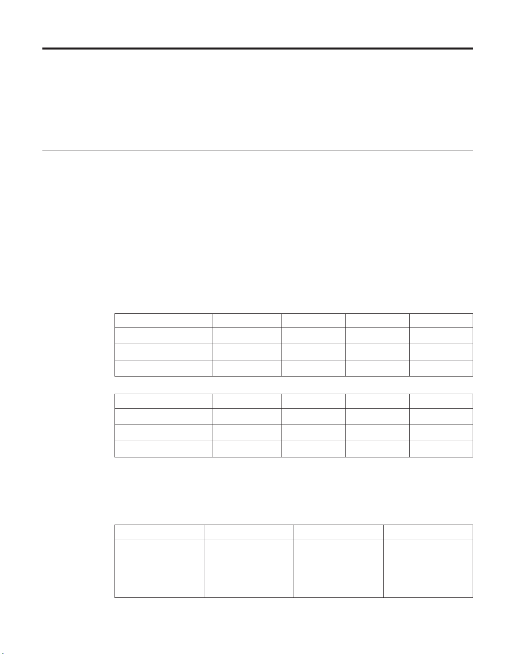
Appendix A. Recommended power line sizes
This appendix describes the recommended AC power line lengths running
from the N series storage system to the power source.
Recommended AC power line sizes
Longer AC power feeds need to be properly designed to preserve voltage
levels to the equipment. The wiring from the breaker panel to the power strip,
which supplies power to the N series storage system and EXP600 expansion
units, can often exceed 50 feet.
Note: Total AC wire length = breaker to wall or ceiling outlet + extension
cable or ceiling drop.
The following table lists the recommended conductor size for 2% voltage drop
for a particular distance in feet (taken from the Radio Engineer’s Handbook).
Table 9. Recommended conductor size for 2% voltage drop
110V, single-phase 20A circuit 30A circuit 40A circuit 50A circuit
25 feet 12 AWG 10 AWG 8 AWG 8 AWG
50 feet 8 AWG 6 AWG 6 AWG 4 AWG
75 feet 6 AWG 4 AWG 4 AWG 2 AWG
220V, single-phase 20A circuit 30A circuit 40A circuit 50A circuit
25 feet 14 AWG 12 AWG 12 AWG 10 AWG
50 feet 12 AWG 10 AWG 8 AWG 8 AWG
75 feet 10 AWG 8 AWG 6 AW G 6 AWG
The following table lists the approximate equivalent wire gauge (American
Wire Gauge (AWG) to Harmonized Cordage).
Table 10. American Wire Gauge (AWG) to Harmonized Cordage
AWG 8 10 12
Harmonized,
4.0 2.5 1.5
mm-mm
mm-mm =
millimeter squared
© Copyright IBM Corp. 2005, 2007 39
Page 70

40
Page 71

Appendix B. FRU/CRU and power cord list for N series products
This appendix contains information about FRU/CRUs and power cords for N
series products.
FRU/CRU list for N series products
For the most current FRU/CRU list for your N series product, see the
following Web site:
www.ibm.com/storage/support/nas/
Power cord list for N series products
The following list details the power cord feature codes (FCs) for N series
products.
FC 9000 (All countries)
Power cord, Rack PDU
v 27 inches
v Rated 250 V/15 A
v Product end uses C14; PDU end uses C13.
FC 9001 Europe and others
Provides power cords for Austria, Belgium, Bolivia, Bulgaria, Chile,
Croatia, Czech Republic, Egypt, Estonia, European Union, Finland,
France, Germany, Greece, Hungary, Iceland, Indonesia, Latvia,
Lebanon, Lithuania, Luxemburg, Morocco, Netherlands, Norway,
Peru, Poland, Portugal, Romania, Russia, Slovakia, Slovenia, Spain,
Suriname, Sweden, Turkey
v 2.5 m (9 feet), unshielded, rated 250 V/10 A.
v Attached plug EL 211 (CEE 7-VII) designed for 200-240 V ac input.
9002 United Kingdom and others
FC
Provides power cords for United Kingdom, Costa Rica, Cyprus,
Guyana, Hong Kong, Ireland, Kuwait, Malta, Oman, Singapore, Sri
Lanka
v 2.5 m (9 feet), unshielded, rated 250 V/10 A.
v Attached plug EL 210 (13A fuse) designed for 200-240 V ac input.
9003 Japan
FC
Provides power cords for Japan
© Copyright IBM Corp. 2005, 2007 41
Page 72

v 1.83 m (6 feet), unshielded, rated 125 V/15 A.
v Attached plug EL 302 (JIS C3306) designed for 100-110 V ac input.
9004 U.S., Six Feet (2 m)
FC
Provides power cords for U.S., Canada, Mexico, Belize, Columbia,
Ecuador, El Salvador, Guatemala, Honduras, Korea, Nicaragua,
Panama, Philippines, Puerto Rico, Saudi Arabia, Thailand, Venezuela
v 1.83 m (6 feet), unshielded, rated 125 V/15 A.
v Attached plug EL 302 (Nema 5-15P) designed for 100-120 V ac
input.
9005 Australia, New Zealand
FC
Provides power cords for Australia, New Zealand, Uruguay
v 2.5 m (9 feet), unshielded, rated 250 V/10 A.
v Attached plug EL 206 (AS 3112) designed for 200-240 V ac input.
9006 Switzerland, Liechtenstein
FC
Provides power cords for Switzerland, Liechtenstein
v 2.5 m (9 feet), unshielded, rated 250 V/10 A.
v Attached plug EL 203 (SEV 1011) designed for 200-240 V ac input.
FC 9007 Argentina
Provides power cords for Argentina
v 2.5 m (9 feet), unshielded, rated 250 V/10 A.
v Attached plug EL 219 (IRAM 2073) designed for 200-240 V ac input.
42
9008 China
FC
Provides power cords for China
v 2.5 m (9 feet), unshielded, rated 250 V/10 A.
v Attached plug EL 602 (GB 2099/GB 1002) designed for 200-240 V ac
input.
9009 Denmark
FC
Provides power cords for Denmark
v 2.5 m (9 feet), unshielded, rated 250 V/10 A.
v Attached plug EL 213 (DHCR 107-2-D1) designed for 200-240 V ac
input.
9010 India, Pakistan, South Africa
FC
Provides power cords for India, Macau, Pakistan, South Africa
v 2.5 m (9 feet), unshielded, rated 250 V/10 A.
v Attached plug EL 208 (BS 164-1, BS 546) designed for 200-240 V ac
input.
FC 9011 Israel
Provides power cords for Israel
Page 73

v 2.5 m (9 feet), unshielded, rated 250 V/10 A.
v Attached plug EL 212 (SI 32) designed for 200-240 V ac input.
9012 Italy
FC
Provides power cords for Italy
v 2.5 m (9 feet), unshielded, rated 250 V/10 A.
v Attached plug EL 502 (CEI 23-16) designed for 200-240 V ac input.
9013 North America (250 V)
FC
Provides power cords for U.S.
v 1.83 m (6 feet), unshielded, rated 250 V/15 A.
v Attached plug EL 309 (NEMA 6-15P) designed for 200-240 V ac
input.
9014 Brazil
FC
Provides power cords for Brazil
v 2.5 m (9 feet), unshielded, rated 250 V/10 A.
v Attached plug EL 211 (NBR 6147/2000) designed for 200-240 V ac
input
9015 Taiwan
FC
Provides 125 V power cords for Taiwan
v 2.5 m (9 feet), unshielded, rated 125 V/15 A.
v Attached plug EL 302 (CNS 10917-3) designed for 100-120 V ac
input.
9016 Taiwan (250 V)
FC
Provides 250 V power cords for Taiwan
v 1.83 m (6 feet), unshielded, rated 250 V/10 A.
v Attached plug EL 610 (CNS 10917, CNS 690) designed for 250 V ac
input.
Appendix B. FRU/CRU and power cord list for N series products 43
Page 74

44
Page 75

Appendix C. IBM System Storage N series documentation
The following lists present an overview of the IBM System Storage N series
hardware and Data ONTAP product libraries, as well as other related
documents.
You can access the documents listed in these tables at the following Web site:
www.ibm.com/storage/support/nas/
N7000 series systems library
v IBM System Storage N7000 Series Hardware and Service Guide, GC26-7953
v IBM System Storage N7000 Series Filer Installation and Setup Instructions,
GC26-7954
v IBM System Storage N7000 Series Gateway Installation and Setup Instructions,
GC26-7956
N5000 series systems library
v IBM System Storage N5000 Series Hardware and Service Guide, GC26-7785
v IBM System Storage N5000 Series Filer Installation and Setup Instructions,
GC26-7784
v IBM System Storage N5000 Series Gateway Installation and Setup Instructions,
GC26-7838
N3300 and N3600 storage systems library
v IBM System Storage N3300 and N3600 Hardware and Service Guide, GC27-2087
v IBM System Storage N3300 Installation and Setup Instructions, GC27-2086
v IBM System Storage N3600 Installation and Setup Instructions, GC27-2089
N3700 storage system library
v IBM System Storage N3700 Hardware and Service Guide, GA32-0515
v IBM System Storage N3700 Installation and Setup Instructions, GA32-0517
© Copyright IBM Corp. 2005, 2007 45
Page 76

EXN1000, EXN2000 and EXN4000 expansion units library
v IBM System Storage EXN1000 Storage Expansion Unit Hardware and Service
Guide, GC26-7802
v IBM System Storage EXN1000 Installation and Setup Instructions, GC26-7786
v IBM System Storage EXN2000 Storage Expansion Unit Hardware and Service
Guide, GA32-0516
v IBM System Storage EXN2000 Installation and Setup Instructions, GC27-2064
v IBM System Storage EXN4000 Storage Expansion Unit Hardware and Service
Guide, GC27-2080
v IBM System Storage EXN4000 Installation and Setup Instructions, GC27-2079
Data ONTAP 7.2 filer library
v IBM System Storage N series Data ONTAP 7.2 Release Notes, GC26-7963
v IBM System Storage N series Data ONTAP 7.2 Active-Active Configuration
Guide, GC26-7964
v IBM System Storage N series Data ONTAP 7.2 File Access and Protocols
Management Guide, GC26-7965
v IBM System Storage N series Data ONTAP 7.2 Storage Management Guide,
GC26-7966
v IBM System Storage N series Data ONTAP 7.2 Data Protection Online Backup
and Recovery Guide, GC26-7967
v IBM System Storage N series Data ONTAP 7.2 Data Protection Tape Backup and
Recovery Guide, GC26-7968
v IBM System Storage N series Data ONTAP 7.2 MultiStore Management Guide,
GC26-7969
v IBM System Storage N series Data ONTAP 7.2 Network Management Guide,
GC26-7970
v IBM System Storage N series Data ONTAP 7.2 Commands: Manual Page
Reference, Volume 1, GC26-7971
v IBM System Storage N series Data ONTAP 7.2 Commands: Manual Page
Reference, Volume 2, GC26-7972
v IBM System Storage N series Data ONTAP 7.2 Upgrade Guide, GC26-7976
v IBM System Storage N series Data ONTAP 7.2 Block Access Management Guide
for iSCSI & FCP, GC26-7973
v IBM System Storage N series Data ONTAP 7.2 System Administration Guide,
GC26-7974
v IBM System Storage N series Data ONTAP 7.2 Software Setup Guide,
GC26-7975
v IBM System Storage N series Data ONTAP 7.2 Core Commands Quick Reference,
GC26-7977
46
Page 77

Data ONTAP 7.1 filer library
v IBM System Storage N series Data ONTAP Release Notes, GC26-7862
v IBM System Storage N series Data ONTAP 7.1 Cluster Installation and
Management Guide, GC26-7790
v IBM System Storage N series Data ONTAP 7.1 File Access and Protocols
Management Guide, GA32-0520
v IBM System Storage N series Data ONTAP 7.1 Storage Management Guide,
GA32-0521
v IBM System Storage N series Data ONTAP 7.1 Data Protection Online Backup
and Recovery Guide, GA32-0522
v IBM System Storage N series Data ONTAP 7.1 Data Protection Tape Backup and
Recovery Guide, GA32-0523
v IBM System Storage N series Data ONTAP 7.1 MultiStore Management Guide,
GA32-0524
v IBM System Storage N series Data ONTAP 7.1 Network Management Guide,
GA32-0525
v IBM System Storage N series Data ONTAP 7.1 Commands: Manual Page
Reference, Volume 1, GA32-0526
v IBM System Storage N series Data ONTAP 7.1 Commands: Manual Page
Reference, Volume 2, GA32-0527
v IBM System Storage N series Data ONTAP 7.1 Upgrade Guide, GC26-7791
v IBM System Storage N series Data ONTAP 7.1 Block Access Management Guide
for iSCSI & FCP, GA32-0528
v IBM System Storage N series Data ONTAP 7.1 System Administration Guide,
GA32-0529
v IBM System Storage N series Data ONTAP 7.1 Software Setup Guide,
GA32-0530
v IBM System Storage N series Data ONTAP 7.1 Core Commands Quick Reference,
GA32-0531
Data ONTAP 7.2 gateway systems library
v IBM System Storage N series Data ONTAP 7.2 Gateway Release Notes,
GC26-7955
v IBM System Storage N series Data ONTAP 7.2 Gateway Software Setup,
Installation, and Management Guide, GC26-7962
v IBM System Storage N series Data ONTAP 7.2 Gateway Connecting Your
System, GC26-7990
v IBM System Storage N series Data ONTAP 7.2 Gateway Planning Guide,
GC26-7957
Appendix C. IBM System Storage N series documentation 47
Page 78

v IBM System Storage N series Data ONTAP 7.2 Gateway Software Upgrade Guide,
GC26-7958
v IBM System Storage N series Data ONTAP 7.2 Gateway Integration Guide for
IBM Storage, GC26-7959
v IBM System Storage N series Data ONTAP 7.2 Gateway Integration Guide for
Hitachi Storage, GC26-7960
v IBM System Storage N series Data ONTAP 7.2 Gateway Integration Guide for
HP XP Storage, GC26-7961
v IBM System Storage N series Data ONTAP 7.2 Gateway Integration Guide for
EMC CLARiiON Storage, GC27-2081
v IBM System Storage N series Data ONTAP 7.2 Gateway Integration Guide for
Fujitsu ETERNUS Storage, GC27-2082
v IBM N series Gateway Data ONTAP 7.2 Integration Guide for IBM SAN Volume
Controller Storage, GC27-2061
v IBM Gateway Data ONTAP 7.2 3PAR Implementation Guide, GC27-2090
v IBM Gateway Data ONTAP 7.2 MetroCluster Guide, GC27-2091
v IBM Gateway Data ONTAP 7.2 Installation Requirements, Quick Start, &
Reference Guide, GC27-2092
Data ONTAP 7.1 gateway systems library
v IBM System Storage N series Gateway Planning Guide, GC26-7839
v IBM System Storage N series Gateway Integration Guide for IBM Storage,
GC26-7840
v IBM System Storage N series Gateway Integration Guide for Hitachi Storage,
GC26-7841
v IBM System Storage N series Gateway Integration Guide for HP Storage,
GC26-7858
v IBM System Storage N series Gateway Software Upgrade Guide, GC26-7859
v IBM System Storage N series Gateway Software Setup, Installation, and
Management Guide, GC26-7886
v IBM System Storage N series Gateway Release Notes, GC26-7837
Other N series and N series-related documents
v IBM System Storage N series Platform Monitoring Guide, GC27-2088
v IBM System Storage N series Diagnostics Guide, GC26-7789
v IBM System Storage N series Introduction and Planning Guide, GA32-0543
v IBM System Storage N series Autosupport Overview, GC26-7854
v IBM System Storage N series: Changing the cluster cfmode Setting in Fibre
Channel SAN Configurations, GC26-7876
48
Page 79

v IBM System Storage N series Fibre Channel Configuration Guide, GC26-7835
v IBM System Storage N series Metrocluster Redbook, REDP-4243-00
v IBM System Storage Systems Safety Notices, G229-9054
v IBM Storage Solution Rack 2101 Rack Installation and Service Guide: Models 200
and N00, GC26-7993
Appendix C. IBM System Storage N series documentation 49
Page 80

50
Page 81

Notices
This information was developed for products and services offered in the
U.S.A.
IBM may not offer the products, services, or features discussed in this
document in other countries. Consult your local IBM representative for
information on the products and services currently available in your area. Any
reference to an IBM product, program, or service is not intended to state or
imply that only that IBM product, program, or service may be used. Any
functionally equivalent product, program, or service that does not infringe on
any IBM intellectual property right may be used instead. However, it is the
user’s responsibility to evaluate and verify the operation of any non-IBM
product, program, or service.
IBM may have patents or pending patent applications covering subject matter
described in this document. The furnishing of this document does not give
you any license to these patents. You can send license inquiries, in writing to:
IBM Director of Licensing
IBM Corporation
North Castle Drive
Armonk, N.Y. 10504-1785
U.S.A.
For additional information, visit the web at:
http://www.ibm.com/ibm/licensing/contact/
The following paragraph does not apply to the United Kingdom or any
other country where such provisions are inconsistent with local law:
INTERNATIONAL BUSINESS MACHINES CORPORATION PROVIDES THIS
PUBLICATION “AS IS” WITHOUT WARRANTY OF ANY KIND, EITHER
EXPRESS OR IMPLIED, INCLUDING, BUT NOT LIMITED TO, THE
IMPLIED WARRANTIES OF NON-INFRINGEMENT, MERCHANTABILITY
OR FITNESS FOR A PARTICULAR PURPOSE. Some states do not allow
disclaimer of express or implied warranties in certain transactions, therefore,
this statement may not apply to you.
This information could include technical inaccuracies or typographical errors.
Changes are periodically made to the information herein; these changes will
be incorporated in new editions of the publication. IBM may make
improvements and/or changes in the product(s) and/or the program(s)
described in this publication at any time without notice.
© Copyright IBM Corp. 2005, 2007 51
Page 82

Any references in this information to non-IBM web sites are provided for
convenience only and do not in any manner serve as an endorsement of those
web sites. The materials at those web sites are not part of the materials for
this IBM product and use of those web sites is at your own risk.
IBM may use or distribute any of the information you supply in any way it
believes appropriate without incurring any obligation to you.
Any performance data contained herein was determined in a controlled
environment. Therefore, the results obtained in other operating environments
may vary significantly. Some measurements may have been made on
development-level systems and there is no guarantee that these measurements
will be the same on generally available systems. Furthermore, some
measurement may have been estimated through extrapolation. Actual results
may vary. Users of this document should verify the applicable data for their
specific environment.
Information concerning non-IBM products was obtained from the suppliers of
those products, their published announcements or other publicly available
sources. IBM has not tested those products and cannot confirm the accuracy
of performance, compatibility or any other claims related to non-IBM
products. Questions on the capabilities of non-IBM products should be
addressed to the suppliers of those products.
Trademarks
52
If you are viewing this information in softcopy, the photographs and color
illustrations may not appear.
The following terms are trademarks of International Business Machines
Corporation in the United States, other countries, or both:
IBM ServerProven
IBM logo System Storage
NetApp, the Network Appliance logo, the bolt design, NetApp–the Network
Appliance Company, Data ONTAP, DataFabric, FAServer, FilerView,
MultiStore, NearStore, NetCache, SecureShare, SnapManager, SnapMirror,
SnapMover, SnapRestore, SnapVault, SyncMirror, and WAFL are registered
trademarks of Network Appliance, Inc. in the United States, and/or other
countries. gFiler, Network Appliance, SnapCopy, Snapshot, and The Evolution
of Storage are trademarks of Network Appliance, Inc. in the United States
and/or other countries and registered trademarks in some other countries.
ApplianceWatch, BareMetal, Camera-to-Viewer, ComplianceClock,
ComplianceJournal, ContentDirector, ContentFabric, EdgeFiler, FlexClone,
Page 83

FlexVol, FPolicy, HyperSAN, InfoFabric, LockVault, Manage ONTAP, NOW,
NetApp on the Web, ONTAPI, RAID-DP, RoboCache, RoboFiler, SecureAdmin,
Serving Data by Design, SharedStorage, Simulate ONTAP, Smart SAN,
SnapCache, SnapDirector, SnapDrive, SnapFilter, SnapLock, SnapMigrator,
SnapSuite, SnapValidator, SohoFiler, vFiler, VFM, Virtual File Manager,
VPolicy, and Web Filer are trademarks of Network Appliance, Inc. in the
United States and other countries. NetApp Availability Assurance and
NetApp ProTech Expert are service marks of Network Appliance, Inc. in the
United States. Spinnaker Networks, the Spinnaker Networks logo, SpinAccess,
SpinCluster, SpinFS, SpinHA, SpinMove, and SpinServer are registered
trademarks of Spinnaker Networks, LLC in the United States and/or other
countries. SpinAV, SpinManager, SpinMirror, SpinRestore, SpinShot, and
SpinStor are trademarks of Spinnaker Networks, LLC in the United States
and/or other countries.
Network Appliance is a licensee of the CompactFlash and CF Logo
trademarks.
Network Appliance NetCache is certified RealSystem compatible.
Microsoft®, Windows®, and Windows NT® are trademarks of Microsoft
Corporation in the United States, other countries, or both.
UNIX is a registered trademark of The Open Group in the United States and
other countries.
Other company, product, or service names may be trademarks or service
marks of others.
Important notes
Processor speeds indicate the internal clock speed of the microprocessor; other
factors also affect application performance.
CD-ROM drive speeds list the variable read rate. Actual speeds vary and are
often less than the maximum possible.
When referring to processor storage, real and virtual storage, or channel
volume, KB stands for approximately 1000 bytes, MB stands for
approximately 1 000 000 bytes, and GB stands for approximately 1 000 000 000
bytes.
When referring to hard disk drive capacity or communications volume, MB
stands for 1 000 000 bytes, and GB stands for 1 000 000 000 bytes. Total
user-accessible capacity may vary depending on operating environments.
Notices 53
Page 84

Maximum internal hard disk drive capacities assume the replacement of any
standard hard disk drives and population of all hard disk drive bays with the
largest currently supported drives available from IBM.
Maximum memory may require replacement of the standard memory with an
optional memory module.
IBM makes no representation or warranties regarding non-IBM products and
services that are ServerProven®, including but not limited to the implied
warranties of merchantability and fitness for a particular purpose. These
products are offered and warranted solely by third parties.
IBM makes no representations or warranties with respect to non-IBM
products. Support (if any) for the non-IBM products is provided by the third
party, not IBM.
Some software may differ from its retail version (if available), and may not
include user manuals or all program functionality.
Electronic emission notices
The following statements apply to this product. The statements for other
products intended for use with this product will appear in their
accompanying manuals.
54
Federal Communications Commission (FCC) Class A Statement
Note: This equipment has been tested and found to comply with the limits for
a Class A digital device, pursuant to Part 15 of the FCC Rules. These limits
are designed to provide reasonable protection against harmful interference
when the equipment is operated in a commercial environment. This
equipment generates, uses, and can radiate radio frequency energy and, if not
installed and used in accordance with the instruction manual, may cause
harmful interference to radio communications. Operation of this equipment in
a residential area is likely to cause harmful interference, in which case the
user will be required to correct the interference at his own expense.
Properly shielded and grounded cables and connectors must be used in order
to meet FCC emission limits. IBM is not responsible for any radio or television
interference caused by using other than recommended cables and connectors
or by unauthorized changes or modifications to this equipment. Unauthorized
changes or modifications could void the user’s authority to operate the
equipment.
This device complies with Part 15 of the FCC Rules. Operation is subject to
the following two conditions: (1) this device may not cause harmful
Page 85

interference, and (2) this device must accept any interference received,
including interference that may cause undesired operation.
Industry Canada Class A Emission Compliance Statement
This Class A digital apparatus complies with Canadian ICES-003.
Avis de conformité à la réglementation d’Industrie Canada
Cet appareil numérique de la classe A est conform à la norme NMB-003 du
Canada.
European Union (EU) Electromagnetic Compatibility Directive
This product is in conformity with the protection requirements of EU Council
Directive 2004/108/EC on the approximation of the laws of the Member
States relating to electromagnetic compatibility. IBM cannot accept
responsibility for any failure to satisfy the protection requirements resulting
from a non-recommended modification of the product, including the fitting of
non-IBM option cards.
This product has been tested and found to comply with the limits for Class A
Information Technology Equipment according to European Standard EN
55022. The limits for Class A equipment were derived for commercial and
industrial environments to provide reasonable protection against interference
with licensed communication equipment.
Attention: This is a Class A product. In a domestic environment this product
may cause radio interference in which case the user may be required to take
adequate measures.
Properly shielded and grounded cables and connectors must be used in order
to reduce the potential for causing interference to radio and TV
communications and to other electrical or electronic equipment. Such cables
and connectors are available from IBM authorized dealers. IBM cannot accept
responsibility for any interference caused by using other than recommended
cables and connectors.
European Community contact:
IBM Technical Regulations
Pascalstr. 100, Stuttgart, Germany 70569
Tele: 0049 (0)711 7851176
Fax: 0049 (0)711 785 1283
e-mail: tjahn@de.ibm.com
Australia and New Zealand Class A statement
Attention: This is a Class A product. In a domestic environment this product
may cause radio interference in which case the user may be required to take
adequate measures.
Notices 55
Page 86
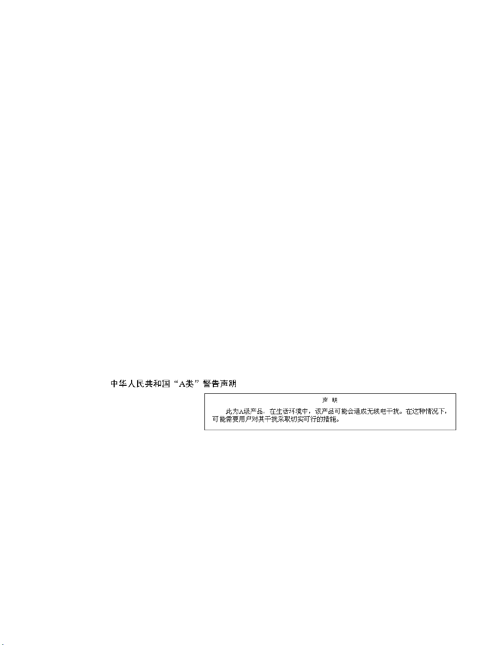
Germany Electromagnetic Compatibility Directive
Zulassungsbescheinigung laut dem Deutschen Gesetz über die
elektromagnetische Verträglichkeit von Geräten (EMVG) vom 18. September
1998 (bzw. der EMC EG Richtlinie 89/336)
Dieses Gerät ist berechtigt, in Übereinstimmung mit dem Deutschen EMVG
das EG-Konformitätszeichen - CE - zu führen.
Verantwortlich für die Konformitätserklärung nach Paragraph 5 des EMVG ist
die: IBM Deutschland Informationssysteme GmbH 70548 Stuttgart.
Informationen in Hinsicht EMVG Paragraph 4 Abs. (1) 4:
Das Gerät erfüllt die Schutzanforderungen nach EN 55024 und
EN 55022 Klasse A.
EN 55022 Klasse A Geräte müssen mit folgendem Warnhinweis versehen
werden: ″Warnung: dies ist eine Einrichtung der Klasse A. Diese Einrichtung
kann im Wohnbereich Funkstörungen verursachen; in diesem Fall kann vom
Betreiber verlangt werden, angemessene Maßnahmen durchzuführen und
dafür aufzukommen.″
Anmerkung: Um die Einhaltung des EMVG sicherzustellen, sind die Geräte
wie in den IBM Handbüchern angegeben zu installieren und zu betreiben.
People’s Republic of China Class A Electronic Emission Statement
56
Page 87
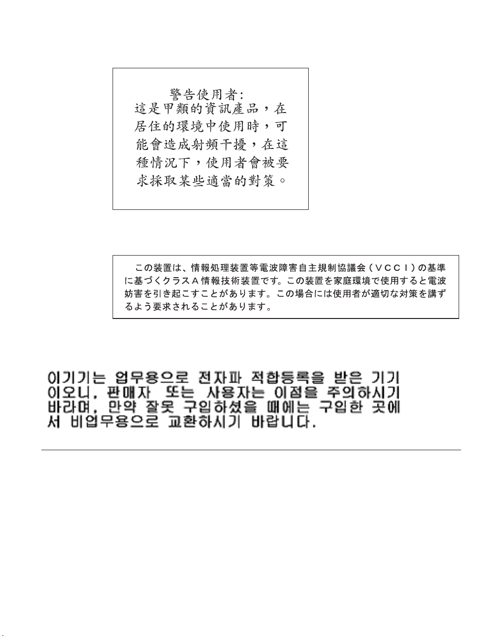
Taiwan Class A warning statement
Japan VCCI Class A ITE Electronic Emission Statement
Korean Class A Electronic Emission Statement
Power cords
For your safety, IBM provides a power cord with a grounded attachment plug
to use with this IBM product. To avoid electrical shock, always use the power
cord and plug with a properly grounded outlet.
IBM power cords used in the United States and Canada are listed by
Underwriter’s Laboratories (UL) and certified by the Canadian Standards
Association (CSA).
For units intended to be operated at 115 volts: Use a UL-listed and
CSA-certified cord set consisting of a minimum 18 AWG, Type SVT or SJT,
Notices 57
Page 88

three-conductor cord, a maximum of 15 feet in length and a parallel blade,
grounding-type attachment plug rated 15 amperes, 125 volts.
For units intended to be operated at 230 volts (U.S. use): Use a UL-listed and
CSA-certified cord set consisting of a minimum 18 AWG, Type SVT or SJT,
three-conductor cord, a maximum of 15 feet in length and a tandem blade,
grounding-type attachment plug rated 15 amperes, 250 volts.
For units intended to be operated at 230 volts (outside the U.S.): Use a cord
set with a grounding-type attachment plug. The cord set should have the
appropriate safety approvals for the country in which the equipment will be
installed.
IBM power cords for a specific country or region are usually available only in
that country or region.
58
Page 89

Index
A
about this document xxiii
how to send your
comments xxviii
AC power line sizes 39
address, IBM xxviii
antistatic ESD strap 1
AT-FCX module
console error messages 23
installing 36
interpreting LEDs 23
removing 36
replacing 35
attention notice vii
C
caution notices vi
Class A electronic emission
notice 54
clearance dimensions 3
command
comments, how to send xxviii
connecting to a power source 15
connections of
console error messages
conventions
device_map 16
fcstat
halt 30, 31, 36
storage disable 37
storage enable 38
expansion
unit to power
source 15
expansion units to an N series
storage system 14
grounded expansion units to an
N series storage system 15
AT-FCX module 23
cooling element, element 1 and
2 27
front operation panel 21
Open loop panic 17
power supply 26
power supply element 1 and
2 26
Soft address panic 17
command xxvi
formatting xxvi
keyboard xxvii
D
danger notices iii
Data ONTAP 7.1 filer
documentation
47
Data ONTAP 7.1 gateway systems
library 48
Data ONTAP 7.2 filer
documentation
46
Data ONTAP 7.2 gateway systems
library 47
disk shelf ID 8
disks
location of LEDs 27
replacing 32
documentation
ONTAP 7.1 filer 47
Data
Data ONTAP 7.1 gateway 48
Data ONTAP 7.2 filer 46
Data ONTAP 7.2 gateway 47
EXN1000, EXN2000 and EXN4000
expansion units 46
IBM System Storage N series 45
N series-related documents 48
N3300 and N3600 storage
system 45
N3700 storage system 45
N5000 series systems 45
N7000 series systems 45
drive addressing 9
drive bay requirements 11
E
edition notice ii
electrical requirements 4
electronic emission Class A
notice 54
electronic emission notices 54
Electronic emission notices
Australia
European Union EMC Directive
Federal Communications
Industry Canada Class A
and New Zealand Class
A statement 55
conformance statement 55
Commission (FCC)
statement 54
emission compliance
statement 55
Electronic emission notices
(continued)
Japanese Voluntary Control
Council for Interference (VCCI)
statement 57
Korean Class A warning
statement 57
Taiwanese Class A warning
statement 57
enclosure services, drive bays
required for 11
environmental
iii
notices
environmental requirements 3
EXN1000, EXN2000 and EXN4000
expansion units library 46
expansion units
connecting to an N series storage
system 14
removing from a single
configuration 30
replacing 29
F
FCC Class A notice 54
fiber-optic cable
handling 13
fire suppression xiii
form, reader comment xxviii
front operation panel
console error messages 21
location of LEDs 20
monitoring the disk shelf ID 20
FRU/CRU list
feature codes 41
G
grounding, expansion units to an N
series storage system 15
H
handling static-sensitive devices 1
hardware service and support xxv
hot-adding error message
Open loop panic 17
Soft address panic 17
hot-adding to an existing loop 15
how to send your comments xxviii
© Copyright IBM Corp. 2005, 2007 59
Page 90

I
IBM
IBM safety information 48
IDs, disk shelf 8
installation
intellectual property 51
xxviii
address
AT-FCX modules 36
before you begin 7
power supply 35
rack viii
site requirements for 1
tools 1
L
labels
drive bay population 8
on the expansion unit 11
safety vi
labels on the expansion unit 16
laser safety vii
LED interpretation
AT-FCX module 23
power supplies 23
LED locations
disks 27
front operation panel 20
power supply 25
license, patents 51
licensing
51
address
Web address 51
N
N series
related documents 48
N series documentation 45
N3300 and N3600 storage system
library 45
N3700 storage system library 45
N5000 series systems library 45
N7000 series systems library 45
notes, important 53
notice, edition ii
notices
attention vii
caution vi
danger iii
electronic emission 54
FCC, Class A 54
safety and environmental iii
types iii
O
optical port terminators vii
P
patents 51
physical characteristics 3
power
grounded
electrical outlet 35
receptacles 35
power cords 57
feature codes 41
power supplies
installing in a expansion unit 35
interpreting LEDs power
supply 23
location of LEDs 25
power switch for 35
removing from an expansion
unit 34
replacing 33
power supply error messages
cooling element, element 1 and
2 27
power supply element 1 and
2 26
R
rack installation
safety viii
rack relocation x
safety x
rack safety viii
reader comment form
processing xxviii
removal of
modules 36
AT-FCX
expansion unit from
daisy-chain 31
expansion units 30
power supplies 34
replacement of
modules 35
AT-FCX
disks 32
expansion unites 29
power supplies 33
requirements
drive bay 11
restrictions, usage vii
rules
drive bays 11
for
S
safety
environmental
labels iii
laser vii
notices iii
rack viii
notices iii
safety (continued)
installation viii
rack
rack relocation x
safety labels vi
speed setting 10
static-sensitive devices, handling 1
T
tasks by document title 45
terminators
optical ports vii
terminology xxvi
trademarks 52
U
United States electronic emission
Class A notice 54
United States FCC Class A
notice 54
usage restrictions vii
W
web sites, related xxv
60
Page 91

Readers’ Comments — We’d Like to Hear from You
IBM System Storage EXN1000 Storage Expansion Unit
Hardware and Service Guide
Publication No. GC26-7802-02
We appreciate your comments about this publication. Please comment on specific errors or omissions, accuracy,
organization, subject matter, or completeness of this book. The comments you send should pertain to only the
information in this manual or product and the way in which the information is presented.
For technical questions and information about products and prices, please contact your IBM branch office, your
IBM business partner, or your authorized remarketer.
When you send comments to IBM, you grant IBM a nonexclusive right to use or distribute your comments in any
way it believes appropriate without incurring any obligation to you. IBM or any other organizations will only use
the personal information that you supply to contact you about the issues that you state on this form.
Comments:
Thank you for your support.
Submit your comments using one of these channels:
v Send your comments to the address on the reverse side of this form.
If you would like a response from IBM, please fill in the following information:
Name
Address
Company or Organization
Phone No. E-mail address
Page 92

_________________________________________________________________________________
Readers’ Comments — We’d Like to Hear from You
GC26-7802-02
Fold
__________________________________________________________________________
and Tape Please do not staple Fold and Tape
NO
POSTAGE
NECESSARY
MAILED IN THE
IF
STATES
UNITED
BUSINESS REPLY MAIL
FIRST-CLASS MAIL PERMIT NO. 40 ARMONK, NEW YORK
Cut or Fold
Line
Along
POSTAGE WILL BE PAID BY ADDRESSEE
International Business Machines Corporation
Information Development
Dept. GZW
9000 South Rita Road
Tuscon, AZ
U.S.A. 85744-0001
__________________________________________________________________________
and Tape Please do not staple Fold and Tape
Fold
GC26-7802-02
Cut
Along
or Fold
Line
Page 93

Page 94

Printed in USA
GC26-7802-02
 Loading...