

Page 1

ETX-DB-ATX
ETX MODULE BASEBOARD
PCB V1.2
Manual Revision 1.0
April 11, 2002
Copyright 2003 by ICP Electronics Inc. All Rights Reserved.
The information in this document is subject to change without prior notice in order to
improve reliability, design and function and does not represent a commitment on the part
of the manufacturer.
In no event will the manufacturer be liable for direct, indirect, special, incidental, or
consequential damages arising out of the use or inability to use the product or
documentation, even if advised of the possibility of such damages.
This document contains proprietary information protected by copyright. All rights are
reserved. No part of this manual may be reproduced by any mechanical, electronic, or
other means in any form without prior written permission of the manufacturer.
Trademarks
ETX-DB-ATX is a registered trademark of ICP Electronics Inc. IBM PC is a registered
trademark of International Business Machines Corporation. Intel is a registered
trademark of Intel Corporation. Other product names mentioned herein are used for
identification purposes only and may be trademarks and/or registered trademarks of their
respective companies
Contents
1. Introduction.........................................................................4
1.1 Specifications.............................................................................4
1.2 What You Have .......................................................................... 5
2. Installation...........................................................................6
2.1 ETX-DB-ATX Board Layout....................................................... 6
2.2 Unpacking Precautions .............................................................8
2.3 LCD Vcc Voltage Selector .........................................................8
2.4 Clear CMOS Setup....................................................................8
2.5 WatchDog Timeout Active Selector........................................... 9
2.6 Internal Buzzer Enable/Disable................................................. 9
2.7 Ethernet Controller Setting........................................................ 9
3. Connection ........................................................................ 10
3.1 ETX Connector X1................................................................... 10
3.2 ETX Connector X2................................................................... 11
3.3 ETX Connector X3................................................................... 12
3.4 ETX Connector X4................................................................... 13
3.5 Floppy Disk Drive Connector ..................................................14
3.6 PCI E-IDE Disk Drive Connector............................................. 15
3.7 Parallel Port ............................................................................. 16
3.8 Serial Ports .............................................................................. 16
3.9 USB Port Connector ................................................................17
3.10 IrDA Infrared Interface Port ...................................................18
3.11 TV-OUT Interface Port ...........................................................18
3.12 VGA Connector...................................................................... 18
3.13 LCD/LVDS Interface Connector ............................................ 19
3.14 LAN RJ45 Connector ............................................................19
3.15 AUDIO JACK .........................................................................20
ETX-DB-ATX
2
Page 2

3.16 PCI BUS Interface ................................................................. 20
3.17 ISA BUS Interface ................................................................. 22
3.18 ATX power connector ............................................................ 23
3.19 Front Panel Pin Header......................................................... 23
3.20 Digital IO connector............................................................... 23
3.21 Keyboard & PS/2 Mouse Connector ..................................... 24
1
Introduction
ETX-DB-ATX is designed for ETX module computer board
applications
The ETX-DB-ATX provides four 100 pins FX8 series connector
to connect ETX module computer board. It also provides all kind of
input/output port, included two parallel ports, two serial ports
RS-232, four USB ports, three audio phone jacks, one VGA CRT
connector, one 48 bits two channels LVDS connector, two PCI
interface slots, one ISA interface slots, two channel IED interface
connectors, one floppy interface connector, one TV-out port, one
IR port, and a PS/2 keyboard/mouse interface.
1.1 Specifications
*Display interface:
Support CRT and LVDS LCD displays simultaneously
*Audio interface:
Connector: Speaker, Mic-in, Line-in.
*IDE interface: supports two PCI Enhanced IDE hard drives
*FDD interface: support up to two floppy disk drives, 5.25”
(360KB and 1.2MB)and/or 3.5”( 720KB, 1.44MB, and
2.88MB)(Multi function with Parallel port)
*Serial ports: Two RS232 ports
*Parallel port: One Parallel port can supports SPP/EPP/ECP
mode (Multi function with Floppy interface)
*PS/2 Mouse/Keyboard interface: easy connection to a
keyboard or PS/2 mouse
*USB interface: four USB ports.
*PCI interface: Two PCI slots.
3
ETX-DB-ATX
ETX-DB-ATX
4
Page 3
*ISA interface: One ISA slots.
*10/100Mbps Ethernet Controller: Intel 82551QM or Realtek
RTL8100 IEEE802.u 100 BASE-TX standard Dual
Auto-sensing interface to 10MBps or 100MBps networks. On
board RJ45 connectors provide for easy connection.
*Power connector: standard ATX power connector
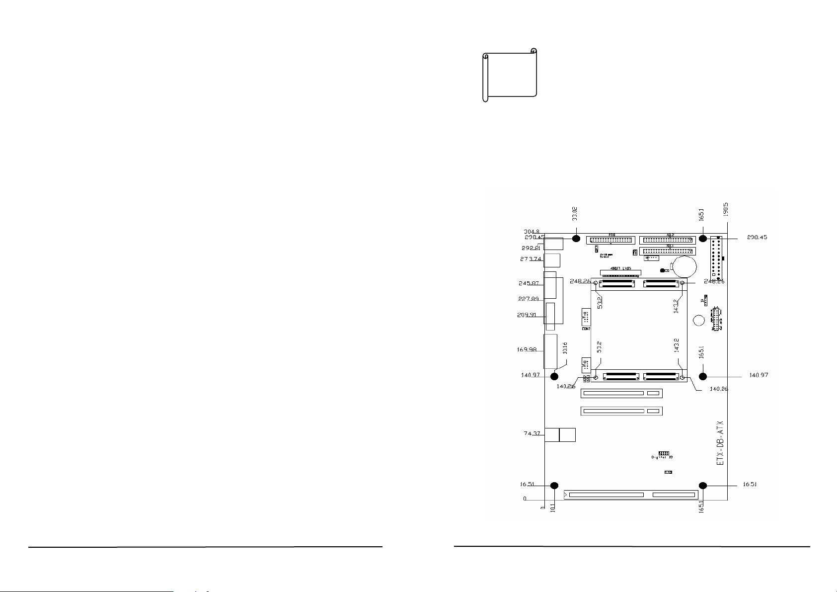
*Dimension: 304mm x 190mm
1.2 What You Have
Before you begin installing the product, please check the
following materials are included in the package:
• 1 ETX-DB-ATX ETX module baseboard
• 1 3.5” IDE flat cable (ATA-66, 44 pin 2.54mm pitch,
457mm)(32200-000052)
• 1 floppy cable (for 3.5” FDD only) (32200-000017)
• 1 serial port cable (for RS232) (32200-0000??)
If any of these items are missing or damaged, contact your
distributor or sales representative immediately.
2
This chapter gives instructions about how to set up the
ETX-DB-ATX hardware, including directions of connecting
peripherals. Before installation, please pay attention to the
unpacking precautions on the following page for safety.
2.1 ETX-DB-ATX Board Layout
Installation
5
ETX-DB-ATX
ETX-DB-ATX
6
Page 4
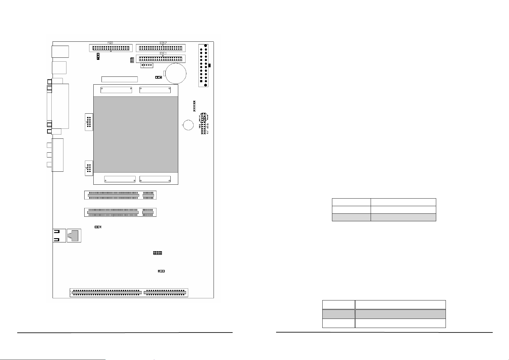
KB/MS
COM1
LPT1
VGA
AUDIO
USB
CN4
CN5 CN6
CN9
CN11
CN10
CN7
USB2
CN21
CN20
ISA1
JP4
CN12
CN2
COM2
CN3
USB3
PSLOT1
PSLOT2
ETX-DB-ATX Layout
CN8
48 BIT LVDS
X3 X4
X1 X2
JP10
CN15
Digital IO
JP6
JP7
CN1
Battery
CN14
CN13
IR
ATX PWER
CN16
CN17
ETX-DB-ATX V1.2
2.2 Unpacking Precautions
Some components of ETX-DB-ATX are very sensitive to static
electric charges and can be damaged by a sudden rush of
power. To protect it from unintended damage, be sure to note
these precautions:
Ground yourself to remove any static charge before touching
the ETX-DB-ATX. You can do it by using a grounded wrist
strap at all times or by frequently touching any conducting
materials that is connected to the ground.
Handle your ETX-DB-ATX by its edges. Don’t touch IC chips,
leads or circuitry if not necessary.
Do not plug any connector or jumper while the power is on.
2.3 LCD Vcc Voltage Selector
The LCD interface connector CN1, CN2, CN6 can provide 5V
or 3.3V power supply by selecting the JP4 to meet the different
LCD requirement.
JP4 DESCRIPTION
1-2 5V
2-3 3.3V
2.4 Clear CMOS Setup
If you need to clear the CMOS Setup (for example, forgot the
password, you should clear the setup and then set the
password again.), you should close the JP6 about 3 seconds,
then open it again. Set back to normal operation mode by open
JP6.
JP6: Clear CMOS Setup (Reserve Function)
•
JP6 DESCRIPTION
1-2 Normal Operation
2-3 Clear CMOS Setup
7
ETX-DB-ATX
ETX-DB-ATX
8
Page 5

2.5 WatchDog Timeout Active Selector
Reading I/O port 443H enables the WatchDog Timer. It should
be triggered before the time-out period ends, otherwise it will
assume the program operation is abnormal and will issue a
reset signal or an interrupt signal. The Watch-Dog Timer is
disabled by reading port 043/843H.detail information on
WatchDog Timer Refer to Appendix A
• JP7: WatchDog Active Select
JP7 DESCRIPTION
1-2 RESET
2-3 IRQ11
2.6 Internal Buzzer Enable/Disable
• CN17 Pin 6 & Pin 8: Internal Buzzer Enable/Disable
CN17 Pin 6 & Pin 8 DESCRIPTION
On(short) Enable
Off(open) Disable
2.7 Ethernet Controller Setting
The On Board Ethernet Controller can be enable or disable by
selecting the JP10.
JP10 DESCRIPTION
1-2 Enable
2-3 Disable
3
Connection
This chapter describes how to connect peripherals, switches
and indicators to the ETX-DB-ATX board.
3.1 ETX Connector X1
X1: PCI-Bus, USB, and Audio
PIN SIGNAL PIN SIGNAL PIN SIGNAL PIN SIGNAL
1 GND 2 GND 51 5V 52 5V
3 PCICLK3 4 PCICLK4 53 PAR 54 SERR#
5 GND 6 GND 55 PERR# 56 RESERVED
7 PCICLK1 8 PCICLK2 57 PME# 58 USB2#
9 REQ3# 10 GNT3# 59 LOCK# 60 DEVSEL#
11 GNT2# 12 3.3V 61 TRDY# 62 USB3#
13 REQ2# 14 GNT1# 63 IRDY# 64 STOP#
15 REQ1# 16 3.3V 65 FRAME# 66 USB2
17 GNT0# 18 RESERVED 67 GND 68 GND
19 5V 20 5V 69 AD16 70 CBE2#
21 SERIRQ 22 REQ0# 71 AD17 72 USB3
23 AD0 24 3.3V 73 AD19 74 AD18
25 AD1 26 AD2 75 AD20 76 USB0#
27 AD4 28 AD3 77 AD22 78 AD21
29 AD6 30 AD5 79 AD23 80 USB1#
31 CBE0# 32 AD7 81 AD24 82 CBE3#
33 AD8 34 AD9 83 5V 84 5V
35 GND 36 GND 85 AD25 86 AD26
37 AD10 38 LINE-IN-L 87 AD28 88 USB0
39 AD11 40 MIC 89 AD27 90 AD29
41 AD12 42 LINE-IN-R 91 AD30 92 USB1
43 AD13 44 ASVCC 93 PCIRST# 94 AD31
45 AD14 46 LINE-OUT-L 95 INTC# 96 INTD#
47 AD15 48 ASGND 97 INTA# 98 INTB#
49 CBE1# 50 LINE-OUT-R 99 GND 100 GND
9
ETX-DB-ATX
ETX-DB-ATX
10
Page 6

3.2 ETX Connector X2
X2: IS A Bu s
PIN SIGNAL PIN SIGNAL PIN SIGNAL PIN SIGNAL
1 GND 2 GND 51 5V 52 5V
3 SD!4 4 SD15 53 SA6 54 IRQ5
5 SD13 6 MASTER# 55 SA7 56 IRQ6
7 SD12 8 DRQ7 57 SA8 58 IRQ7
9 SD11 10 DACK7# 59 SA9 60 SYSCLK
11 SD10 12 DRQ6 61 SA10 62 REFSH#
13 SD9 14 DACK6# 63 SA11 64 REQ1
15 SD8 16 DRQ5 65 SA12 66 DACK1#
17 MEMW# 18 DACK5# 67 GND 68 GND
19 MEMR# 20 DRQ0 69 SA13 70 DRQ3
21 LA17 22 DACK0# 71 SA14 72 DACK3#
23 LA18 24 IRQ14 73 SA15 74 IOR#
25 LA19 26 IIQR15 75 SA16 76 IOW#
27 LA20 28 IRQ12 77 SA18 78 SA17
29 LA21 30 IRQ11 79 SA19 80 SMEMR#
31 LA22 32 IRQ10 81 IOCHRDY 82 AEN
33 LA23 34 IOCS16# 83 5V 84 5V
35 GND 36 GND 85 SD0 86 SMEMW#
37 SBHE# 38 MEMCS16# 87 SD2 88 SD1
39 SA0 40 OSC 89 SD3 90 ZOWS#
41 SA1 42 BALE 91 DRQ2 92 SD4
43 SA1 44 TC 93 SD5 94 IRQ9
45 SA3 46 DACK2# 95 SD6 96 SD7
47 SA4 48 IRQ3 97 IOC HK#. 98 RSTDRV
49 SA5 50 IRQ4 99 GND 100 GND
11
ETX-DB-ATX
3.3 ETX Connector X3
X3: VGA, LCD, Video, COM1, COM2, LPT/Floppy, Irda, Mouse,
and Keyboard
PIN SIGNAL PIN SIGNAL PIN SIGNAL PIN SIGNAL
1 GND 2 GND 51 LPT/FLPY# 52 RESERVED
3 R 4 B 53 5V 54 GND
5 CRTHSYNC 6 G 55 STB# 56 AFD#
7 CRTVSYNC 8 DDCSCL 57 RESERVED 58 PD7
9 N.C. 10 DDCSDA 59 IRRX 60 ERR#
11 TXCLK1- 12 TXOUT13- 61 IRTX 62 PD6
13 TXCLK1+ 14 TXOUT13+ 63 RXD2 64 INIT#
15 GND 16 GND 65 GND 66 GND
17 TXOUT11+ 18 TXOUT12+ 67 RTS2# 68 PD5
19 TXOUT11- 20 TXOUT12- 69 DTR2# 70 SLIN#
21 GND 22 GND 71 DCD2# 72 PD4
23 TXOUT03- 24 TXOUT10+ 73 DSR2# 74 PD3
25 TXOUT03+ 26 TXOUT10- 75 CTS2# 76 PD2
27 GND 28 GND 77 TXD2 78 PD1
29 TXOUT02- 30 TXCLK0+ 79 RI2# 80 PD0
31 TXOUT02+ 32 TXCLK0- 81 5V 82 5V
33 GND 34 GND 83 RXD1 84 ACK#
35 TXOUT00+ 36 TXOUT01+ 85 RTS1# 86 BUSY#
37 TXOUT00- 38 TXOUT01- 87 DTR1# 88 PE
39 5V 40 5V 89 DCD1# 90 SLCT
41 N.C. 42 N.C. 91 DSR1# 92 MSCLK
43 N.C. 44 FPENABKL 93 CTS1# 94 MSDATA
45 N.C. 46 FPENAVDD 95 TXD1 96 KBCLK
47 TV-CVBS 48 TV-Y 97 RI1# 98 KBDATA
49 TV-SYNC 50 TV-C 99 GND 100 GND
ETX-DB-ATX
12
Page 7

3.4 ETX Connector X4
X4: IDE1, IDE2, and Miscellaneous
PIN SIGNAL PIN SIGNAL PIN SIGNAL PIN SIGNAL
1 GND 2 GND 51 SIED_IOW# 52 PIDE_IOR#
3 5VSB 4 PWGIN 53 SIDE_DRQ 54 PIDE_IOW#
5 PS_ON 6 SPEAKER 55 SIDE_D15 56 PIDE_DRQ
7 PWRBTN# 8 VBAT 57 SIDE_D0 58 PIDE_D15
9 KBINH 10 N.C. 59 SIDE_D14 60 PIDE_D0
11 WDTACT# 12 N.C. 61 SIDE_D1 62 PIDE_D14
13 ROMKBCS# 14 N.C. 63 SIDE_D13 64 PIDE_D1
15 ROMCS# 16 I2CCLK 65 GND 66 GND
17 5V 18 5V 67 SIDE_D2 68 PIDE_D13
19 OVRCUR 20 DIOCS# 69 SIDE_D12 70 PIDE_D2
21 EXTSMI# 22 I2CDATA 71 SIDE_D3 72 PIDE_D12
23 SMBCLK 24 SMBDATA 73 SIDE_D11 74 PIDE_D3
25 SIDE_CS3# 26 N.C. 75 SIDE_D4 76 PIDE_D11
27 SIDE_CS1# 28 DASP_S 77 SIDE_D10 78 PIDE_D4
29 SIDE_A2 30 PIDE_CS3# 79 SIDE_D5 80 PIDE_D10
31 SIDE_A0 32 PIDE_CS1# 81 5V 82 5V
33 GND 34 GND 83 SIDE_D9 84 PIDE_D5
35 PDIAG_S 36 PIDE_A2 85 SIDE_D6 86 PIDE_D9
37 SIDE_A1 38 PIDE_A0 87 SIDE_D8 88 PIDE_D6
39 SIDE_IRQ# 40 PIDE_A1 89 RING# 90 N.C.
41 N.C. 42 N.C. 91 N.C. 92 PIDE_D8
43 SIDE_DACK# 44 PIDE_IRQ# 93 N.C. 94 SIDE_D7
45 SIDE_IORDY 46 PIDE_DACK# 95 N.C. 96 PIDE_D7
47 SIDE_IOR# 48 PIDE_IORDY 97 N.C. 98 IDERST#
49 5V 50 5V 99 GND 100 GND
3.5 Floppy Disk Drive Connector
ETX-DB-ATX board is equipped with a 34-pin daisy-chain
driver connector cable.
CN4: FDC CONNECTOR
PIN NO. DESCRIPTION PIN NO. DESCRIPTION
1 GROUND 2 REDUCE WRITE
3 GROUND 4 N/C
5 GROUND 6 N/C
7 GROUND 8 INDEX#
9 GROUND 10 MOTOR ENABLE A#
11 GROUND 12 DRIVE SELECT B#
13 GROUND 14 DRIVE SELECT A#
15 GROUND 16 MOTOR ENABLE B#
17 GROUND 18 DIRECTION#
19 GROUND 20 STEP#
21 GROUND 22 WRITE DATA#
23 GROUND 24 WRITE GATE#
25 GROUND 26 TRACK 0#
27 GROUND 28 WRITE PROTECT#
29 GROUND 30 READ DATA#
31 GROUND 32 SIDE 1 SELECT#
33 GROUND 34 DISK CHANGE#
13
ETX-DB-ATX
ETX-DB-ATX
14
Page 8

3.6 PCI E-IDE Disk Drive Connector
For IDE HDD connection, The ETX-DB-ATX was designed
with two 2.54mm standard IDE connector (CN13, CN14)
CN13: 40-pin Primary IDE Interface Connector
CN14: 40-pin Secondly IDE Interface Connector
3.7 Parallel Port
This port is usually connected to a printer, The ETX-DB-ATX
includes an on-board parallel port (CN11), accessed through a
25 pin D-sub connector.
PIN
NO.
1 RESET# 2 GROUND
3 DATA 7 4 DATA 8
5 DATA 6 6 DATA 9
7 DATA 5 8 DATA 10
9 DATA 4 10 DATA 11
11 DATA 3 12 DATA 12
13 DATA 2 14 DATA 13
15 DATA 1 16 DATA 14
17 DATA 0 18 DATA 15
19 GROUND 20 N/C
21 IDE DRQ 22 GROUND
23 IOW# 24 GROUND
25 IOR# 26 GROUND
27 IDE CHRDY 28 GROUND
29 IDE DACK 30 GROUND–DEFAULT
31 INTERRUPT 32 N/C
33 SA1 34 N/C
35 SA0 36 SA2
37 HDC CS0# 38 HDC CS1#
39 HDD ACTIVE# 40 GROUND
DESCRIPTION
PIN
NO.
DESCRIPTION
• CN11: Parallel Port1 D-sub Connector
PIN
NO.
1 STROBE# 14 AUTO FORM FEED #
2 DATA 0 15 ERROR#
3 DATA 1 16 INITIALIZE
4 DATA 2 17 PRI NTER SELECT LN#
5 DATA 3 18 GROUND
6 DATA 4 19 GROUND
7 DATA 5 20 GROUND
8 DATA 6 21 GROUND
9 DATA 7 22 GROUND
10 ACKNOWLEDGE 23 GROUND
11 BUSY 24 GROUND
12 PAPER EMPTY 25 GROUND
13 PRINTER SELECT
DESCRIPTION
PIN
NO.
DESCRIPTION
3.8 Serial Ports
The ETX-DB-ATX offers two serial ports. These ports let you
connect to serial devices or a communication network. One
9-pin D-SUB connector, one 10-pin header, The detailed pin
15
ETX-DB-ATX
ETX-DB-ATX
16
Page 9

assignment of the connectors are specified as following
tables:
• CN9: Serial Port1 Connector (9-pin D-sub)
3 USBD1+ 3 USBD0+
4 GND 4 GND
•CN3: Internal USB Connector
PIN NO. DESCRIPTION
1 DATA CARRIER DETECT (DCD)
2 RECEIVE DATA (RXD)
3 TRANSMIT DATA (TXD)
4 DATA TERMINAL READY (DTR)
5 GROUND (GND)
6 DATA SET READY (DSR)
7 REQUEST TO SEND (RTS)
8 CLEAR TO SEND (CTS)
9 RING INDICATOR (RI)
• CN2: Serial Port2 Connector (10-pin Header/W Housing)
PIN NO. DESCRIPTIO N PIN NO. DESCRIPTIO N
1 DCD 2 DSR
3 RX 4 RTS
5 TX 6 CTS
7 DTR 8 RI
9 GND 10 N/C
PIN NO. DESCRIPTION PIN NO. DESCRIPTIO N
1 VCC 5 GND
2 USBD2- 6 USBD3+
3 USBD2+ 7 USBD34 GND 8 VCC
3.10 IrDA Infrared Interface Port
• CN16: IrDA connector
PIN NO. DESCRIPTION
1 VCC
2 N.C.
3 IRRX
4 Ground
5 IRTX
3.11 TV-OUT Interface Port
• CN8: TV-out connector
PIN
NO.
1 TV-SYNC 2 TV-Y
3 GND 4 TV-C
5 GND 6 TV-CVBS
DESCRIPTION PIN NO.
DESCRIPTION
3.9 USB Port Connector
The ETX-DB-ATX provides four USB interfaces, which gives
the completed plug and play, for up to 127 external devices.
• CN5: External USB Connector
UP PORT DOWN PORT
PIN NO. DESCRIPTION PIN NO. DESCRIPTIO N
1 VCC 1 VCC
2 USBD1- 2 USBD0-
17
ETX-DB-ATX
3.12 VGA Connector
The ETX-DB-ATX built-in 15-pin VGA connector accepts the
CRT monitor.
• CN10: 15-pin Female Connector
1 RED 2 GREEN
3 BLUE 4 NC
5 GROUND 6 GROUND
7 GROUND 8 GROUND
ETX-DB-ATX
18
Page 10

9 NC 10 GROUND
11 NC 12 DDC DAT
13 HSY NC 14 VSYNC
15 DDCCLK
3.13 LCD/LVDS Interface Connector
The ETX-DB-ATX provides one 30-pin connector for the
LVDS flat panel interface.
• CN12: Two channel 48 bits LVDS Interface Connector
PIN NO. Description
1 GND 2 GND
3 TxOUT03+ 4 TxOUT035 TxCLKOUT0+ 6 TxCLKOUT07 TxOUT02+ 8 TxOUT02-
9 TxOUT01+ 10 TxOUT0111 TxOUT00+ 12 TxOUT0013 GND 14 GND
15 TxOUT13+ 16 TxOUT1317 TxCLKOUT1+ 18 TxCLKOUT119 TxOUT12+ 20 TxOUT1221 TxOUT11+ 22 TxOUT1123 TxOUT10+ 24 TxOUT1025 GND 26 GND
27 PLCD(5V/3.3V) 28 PLCD(5V/3.3V)
29 PLCD(5V/3.3V) 30 PLCD(5V/3.3V)
PIN
NO.
Description
3.14 LAN RJ45 Connector
The ETX-DB-ATX built-in RJ45 LAN connector is for
10/100Mbps Ethernet. The onboard LAN Chip is Intel
82551QM or RealTek RTL8100BL.(IDSEL# = AD26, INTx# =
INTA#, REQx# = REQ1#, GNTx# = GNT1#)
2 TX- 6 RX3 RX+ 7 GND
4 GND 8 GND
3.15 AUDIO JACK
• CN7: Audio Jack
3.16 PCI BUS Interface
• PSLOT1: PCI Slot 1
• PSLOT2: PCI Slot 2
PCI Routing List
SIGNAL PIN No. PSLOT 1 PSLOT 2
REQ# B18
GNT# A17
CLOCK B16
IDSEL A26
INTA# A6
INTB# B7
INTC# A7
INTD# B8
color Signal
Lime Li ne-o ut
Bl ue Line- i n
Pink MIC
REQ0# REQ1#
GNT0# GNT1#
PCICLK1 PCICLK2
AD19 AD20
A B
B C
C D
D A
• CN20, CN21: LAN RJ45 Connector
1 TX+ 5 GND
19
ETX-DB-ATX
ETX-DB-ATX
20
Page 11

A
A
PSLOT1~PSLOT2: PCI Bus pin assignment
•
A B
NO. Signal NO. Sig nal N O. Signal NO. Single
1
3
5
7
9
11
13
15
17
19
21
23
25
27
29
31
33
35
37
39
41
43
45
47
49
51 KEY 52 CBE0# 51 KEY 52 AD8
53
55 AD4 56
57 AD2 58 AD0 57
59
61
N.C.
N.C.
+5V
INTC#
N.C.
N.C.
GND
PCIRST#
GNT#
PME#
3.3V
AD26
AD24
3.3V
AD20
AD18
3.3V
GND
GND
3.3V
N.C.
PAR
3.3V
AD11
AD9
3.3V
+5V
+5V
2 +12V 1 -12V 2
4
6 INTA# 5
8
10
12
14
16
18
20 AD30 19
22 AD28 21 AD29 22
24
26 IDSEL 25
28 AD22 27 AD23 28
30
32 AD16 31
34 FRAME# 33 CBE2# 34
36 TRDY# 35 IRDY# 36
38 STOP# 37 DEVSEL# 38
40
42
44 AD15 43
46 AD13 45 AD14 46
48 GND 47 AD12 48 AD10
50 KEY 49
54 AD6 53 AD7 54
60
62
N.C.
+5V
+5V
GND
N.C.
+5V
GND
GND
GND
N.C.
GND
GND
N.C.
+5V
3
GND
+5V
7 INTB# 8 INTD#
9
N.C.
11
13
15
17
23 AD27 24 AD25
29 AD21 30 AD19
39 LOCK# 40 PERR#
41
55 AD5 56 AD3
59
61 +5V 62 +5V
N.C.
GND
GND
GND
+5V
3.3V
3.3V
3.3V
3.3V
GND
GND
+5V
N.C.
4
6
10
12
14
16 PCICLK
18 REQ#
20 AD31
26 CBE3#
32 AD17
42 SERR#
44 CBE1#
50 KEY
58 AD1
60
N.C.
+5V
N.C.
GND
N.C.
GND
GND
GND
3.3V
GND
GND
3.3V
N.C.
3.17 ISA BUS Interface
• ISA1: ISA Slot 1
ISA1: ISA Bus pin assignment
•
B C D
NO. Signal NO. Signal NO Signal NO Signal
1 IOCHCK# 33 GND 1 SBHE# 1 MEMCS16#
2 SD7 34 IRSTDRV 2 LA23 2 IOCS16#
3 SD6 35 VCC 3 LA22 3 IRQ10
4 SD5 36 IRQ9 4 LA21 4 IRQ11
5 SD4 37 -5V 5 LA20 5 IRQ12
6 SD3 38 DRQ2 6 LA19 6 IRQ15
7 SD2 39 -12V 7 LA18 7 IRQ14
8 SD1 40 ZWS 8 LA17 8 DACK0#
9 SD0 41 +12V 9 MEMR# 9 DREQ0
10 IOCHRDY 42 GND 10 MEMW# 10 DACK5#
11
12 LA19 44 SMEMR# 12 SD9 12 DACK6#
13 LA18 45 IOW# 13 SD10 13 DREQ6
14 LA17 46 IOR# 14 SD11 14 DACK7#
15 SA16 47 DACK3# 15 SD12 15 DREQ7
16 SA15 48 DRQ3 16 SD13 16 VCC
17 SA14 49 DACK1# 17 SD14 17 MASTER#
18 SA13 50 DRQ1 18 SD15 18 GND
19 SA12 51 REFRESH#
20 SA11 52 SYSCLK
21 SA10 53 IRQ7
22 SA9 54 IRQ6
23 SA8 55 IRQ5
24 SA7 56 IRQ4
25 SA6 57 IRQ3
26 SA5 58 DACK2
27 SA4 59 TC
28 SA3 60 BALE
29 SA2 61 VCC
30 SA1 62 OSC
31 SA0 63 GND
32 GND 64 GND
EN 43 SMEMW# 11 SD8 11 DREQ5
21
ETX-DB-ATX
ETX-DB-ATX
22
Page 12

3.18 ATX power connector
PW1: ATX power connector pin assignment
•
PIN NAME PIN NAME
1 +3.3V 11 +3.3V
2 +3.3V 12 -12V
3 GND 13 GND
4 +5V 14 PS_ON
5 GND 15 GND
6 +5V 16 GND
7 GND 17 GND
8 PWR OK 18 -5V
9 STB5V 19 +5V
10 +12V 20 +5V
ATX(PW1)
3.19 Front Panel Pin Header
CN17: Front Panel Pin Header pin assignment
•
Font Panel Pin Header (CN17)
PIN NAME PIN NAME
1 Power LED+ 2 External Buzzer+
3 Power LED+ 4 GND
5 GND 6 Inter nal Buzze r7 K/B Lock 8 External Buzzer-
9 Power LED- 10 N.C.
11 Power Button1 12 HDD LED13 Power Button2 14 HDD LED+
15 N.C. 16 N.C.
17 N.C. 18 Reset button1
19 GND 20 Reset button2
3.20 Digital IO connector
CN1: Digital IO connector pin assignment
•
PIN NAME PIN NAME
1 GND 2 +5V
3 OUT3 4 OUT2
5 OUT1 6 OUT0
7 IN3 8 IN2
9 IN1 10 IN0
Digital IO(CN1)
3.21 Keyboard & PS/2 Mouse Connector
A 6-pin mini DIN connector (CN6) is located on the mounting
bracket for easy connection to a keyboard or PS/2 mouse. The
card comes with a cable to convert from the 6-pin mini-DIN
connector to two 6-pin mini-DIN connector for keyboard and
mouse connection
• CN6: Top 6-pin Mini-DIN Mouse Connector
PIN NO. DESCRIPTIO N
1 MOUSE DATA
2 N.C.
3 GROUND
4 +5V
5 MOUSE CLOCK
6 N.C.
• CN6: Bottom 6-pin Mini-DIN Keyboard Connector
PIN NO. DESCRIPTIO N
1 KEYBOARD DATA
2 N.C.
3 GROUND
4 +5V
5 KEYBOARD CLOCK
6 N.C.
23
ETX-DB-ATX
ETX-DB-ATX
24
 Loading...