

Page 1

ERserver
IBM eServer xSeries x382
Type 8834
Hardware Maintenance Manual and Troubleshooting
Guide
Page 2

Page 3

ER s e r v e r
IBM eServer xSeries x382
Type 8834
Hardware Maintenance Manual and Troubleshooting
Guide
Page 4

Note
Before using this information and the product it supports, read Appendix C, “Notices”, on page 135.
The most recent version of this document is available at http://www.ibm.com/pc/support.
First Edition (August 2003)
© Copyright International Business Machines Corporation 2002. All rights reserved.
US Government Users Restricted Rights – Use, duplication or disclosure restricted by GSA ADP Schedule Contract
with IBM Corp.
Page 5

About this manual
This manual contains diagnostic information, a Symptom-to-FRU index, service
information, error codes, error messages, and configuration information for the IBM
Eserver xSeries x382 Type 8834 server.
To diagnose server problems, always start with “General checkout” on page 21.
Important: The field replaceable unit (FRU) procedures are intended for trained
servicers who are familiar with IBM xSeries products. See the parts
listing in “System” on page 92 to determine if the component being
replaced is a customer replaceable unit (CRU) or a field replaceable
unit (FRU).
Important safety information
Be sure to read all caution and danger statements in this book before performing
any of the instructions. See “Safety information” on page 95.
Leia todas as instruções de cuidado e perigo antes de executar qualquer operação.
Prenez connaissance de toutes les consignes de type Attention et Danger avant de
procéder aux opérations décrites par les instructions.
®
Online support
Lesen Sie alle Sicherheitshinweise, bevor Sie eine Anweisung ausführen.
Accertarsi di leggere tutti gli avvisi di attenzione e di pericolo prima di effettuare
qualsiasi operazione.
Lea atentamente todas las declaraciones de precaución y peligro ante de llevar a
cabo cualquier operación.
WARNING: Handling the cord on this product or cords associated with accessories
sold with this product, will expose you to lead, a chemical known to the State of
California to cause cancer, and birth defects or other reproductive harm. Wash
hands after handling.
ADVERTENCIA: El contacto con el cable de este producto o con cables de
accesorios que se venden junto con este producto, pueden exponerle al plomo, un
elemento químico que en el estado de California de los Estados Unidos está
considerado como un causante de cancer y de defectos congénitos, además de
otros riesgos reproductivos. Lávese las manos después de usar el producto.
You can download the most current diagnostic, BIOS flash, and device driver files
from http://www.ibm.com/pc/support on the World Wide Web.
© Copyright IBM Corp. 2002 iii
Page 6

iv IBM eServer xSeries x382 Type 8834: Hardware Maintenance Manual and Troubleshooting Guide
Page 7

Contents
About this manual .......................iii
Important safety information ....................iii
Online support .........................iii
Chapter 1. General information...................1
Notices and statements used in this book ...............1
Related publications .......................2
Features and specifications.....................3
What your server offers ......................4
Updating device drivers ......................5
Controls and LEDs ........................6
Server power features.......................8
Turning on the server ......................8
Turning off the server ......................9
Major components of your server ..................10
Option connectors........................12
Internal connectors .......................13
External connectors .......................15
Chapter 2. Configuring your server ................17
Using the Configuration/Setup Utility program .............17
Starting the Configuration/Setup Utility program ............17
Password ..........................18
Using the LSI Logic Configuration Utility program ............18
Starting the LSI Logic Configuration Utility program ..........18
Formatting a SCSI hard disk drive .................19
Using ServeRAID Manager ....................19
Configuring the Gigabit Ethernet controller...............20
Updating BIOS .........................20
Chapter 3. Diagnostics .....................21
General checkout ........................21
SEL overview .........................22
EFI-based SELViewer task ....................23
xSeries 382 SEL data tables ....................23
xSeries 382 machine check error handling...............25
Classification of errors .....................25
Error types .........................26
Error signaling ........................26
Error reporting ........................27
Thresholding.........................28
SEL event log format for machine check errors ............29
xSeries 382 PCI device IDs ...................31
POST error codes and messages ..................32
Debug methodology and FRU isolation ................32
Memory ..........................32
Microprocessor debug methodology: ................33
Microprocessor FRU isolation ..................34
Microprocessor - Late Self-test ...................34
Late self-test display ......................34
Late self-test usage notes ....................34
Watch dog timer .......................35
Fault resilient boot (FRB) ....................35
© Copyright IBM Corp. 2002 v
Page 8

FRB3 - BSP reset failures ....................35
FRB2 - BSP POST failures. ...................35
FRB1 - BSP self-test failures. ..................36
FRB debug methodology: ....................36
FRB FRU isolation ......................37
POST codes ..........................37
Beep Codes ..........................37
Running system diagnostics ....................37
Setting test options .......................38
Interpreting test results ......................38
Getting help on individual tests ...................38
Viewing system information ....................38
Viewing the test log .......................38
EFI service partition .......................39
Service partition requirements ...................39
Installing service partition files ...................39
Installation requirements .....................39
Installing the files ........................40
Booting the server from the service partition ..............40
Memory errors .........................40
Error symptom charts ......................41
Small computer system interface messages ..............41
Clearing CMOS.........................41
BIOS recovery mode.......................42
Support telephone numbers ....................42
Chapter 4. Customer replaceable units ...............43
Installation guidelines ......................43
System reliability guidelines ...................43
Handling static-sensitive devices .................44
Removing the bezel .......................45
Installing internal drives......................45
Installing a hot-swap drive....................46
Completing the installation.....................47
Replacing the bezel ......................47
Cabling the server.......................48
Updating your server configuration.................48
Chapter 5. Service replaceable units ................49
Cover removal and replacement ..................49
Working with adapters ......................50
Adapter considerations .....................50
CD-ROM drive removal and replacement ...............51
Hot-swap fan removal and replacement ................52
Hot-swap power supply removal and replacement ............54
Fan assembly and air baffle removal and replacement ..........56
PCI riser assembly removal and replacement..............57
Adapter removal and replacement ..................60
Memory DIMMs removal and replacement ...............63
Front panel board removal and replacement ..............65
SCSI backplane removal and replacement...............66
Peripheral bay removal and replacement ...............67
Power supply bay removal and replacement ..............68
System board removal and replacement ...............70
System board componets .....................72
System board jumpers ......................73
vi IBM eServer xSeries x382 Type 8834: Hardware Maintenance Manual and Troubleshooting Guide
Page 9

Microprocessor removal and replacement ...............74
Power pod removal and replacement.................75
System battery .........................76
Battery removal and replacement .................76
Chapter 6. Symptom-to-FRU index .................79
Beep codes ..........................79
Recovery beep codes ......................80
BMC generated beep codes ....................80
Error codes - video display ....................81
Error symptoms ........................86
Power supply LED errors .....................87
SCSI error codes ........................87
Undetermined problems .....................88
Problem determination tips ....................89
Chapter 7. Parts listing, x382 Type 8834 (models 11X and 32X)......91
System............................92
Appendix A. Getting help and technical assistance ..........93
Before you call .........................93
Using the documentation .....................93
Getting help and information from the World Wide Web ..........93
Software service and support ...................94
Hardware service and support ...................94
Appendix B. Related service information ..............95
Safety information........................95
General safety ........................95
Electrical safety........................96
Safety inspection guide .....................97
Handling static-sensitive devices .................98
Grounding requirements ....................98
Safety notices (multilingual translations)...............99
Appendix C. Notices ......................135
Edition notice .........................135
Trademarks..........................136
Important notes ........................136
Product recycling and disposal ..................137
Electronic emission notices ....................137
Federal Communications Commission (FCC) statement ........137
Industry Canada Class A emission compliance statement ........138
Australia and New Zealand Class A statement ............138
United Kingdom telecommunications safety requirement ........138
European Union EMC Directive conformance statement ........138
Taiwanese Class A warning statement ...............139
Chinese Class A warning statement................139
Japanese Voluntary Control Council for Interference (VCCI) statement 139
Power cords .........................139
Index ............................143
Contents vii
Page 10

viii IBM eServer xSeries x382 Type 8834: Hardware Maintenance Manual and Troubleshooting Guide
Page 11

Chapter 1. General information
The IBM Eserver xSeries x382 Type 8834 server is a high-performance server
based on IBM X-Architecture
capable, if this feature is supported by your operating system. It is ideally suited for
networking environments that require superior microprocessor performance, efficient
memory management, flexibility, and large amounts of reliable data storage.
Your server contains several IBM X-Architecture technologies, which provide
increased performance, reliability, and availability. The X-Architecture technologies
provided in your server include the recent advancements in X-Architecture features.
For more information about the X-Architecture features, see “What your server
offers” on page 4. You can obtain more information about the IBM X-Architecture
technologies and features at
http://www.ibm.com/pc/us/eserver/xseries/xarchitecture/.
Performance, ease of use, reliability, and expansion capabilities were key
considerations in the design of your server. These design features make it possible
for you to customize the system hardware to meet your needs today, while
providing flexible expansion capabilities for the future.
You can obtain up-to-date information about your server model and other IBM
server products at http://www.ibm.com/pc/us/eserver/xseries/.
Note: The illustrations in this document might differ slightly from your hardware.
™
technologies. It is symmetric multiprocessing (SMP)
Notices and statements used in this book
The caution and danger statements that appear in this book are also in the
multilingual Safety Information book, which is on the IBM xSeries Documentation
CD. Each statement is numbered for reference to the corresponding statement in
the Safety Information book.
The following notices and statements are used in the documentation:
v Notes: These notices provide important tips, guidance, or advice.
v Important: These notices provide information or advice that might help you avoid
inconvenient or problem situations.
v Attention: These notices indicate potential damage to programs, devices, or
data. An attention notice is placed just before the instruction or situation in which
damage could occur.
v Caution: These statements indicate situations that can be potentially hazardous
to you. A caution statement is placed just before the description of a potentially
hazardous procedure step or situation.
v Danger: These statements indicate situations that can be potentially lethal or
extremely hazardous to you. A danger statement is placed just before the
description of a potentially lethal or extremely hazardous procedure step or
situation.
© Copyright IBM Corp. 2002 1
Page 12

Related publications
This Hardware Maintenance Manual and Troubleshooting Guide provide information
to help you solve the problem yourself or to provide helpful information to a service
technician. In addition to this Hardware Maintenance Manual and Troubleshooting
Guide, the following documentation comes with your server:
v Installation Guide
This printed publication contains setup and installation instructions.
v User’s Guide
This publication is provides general information about your server, including
information about features, how to configure the server, how to use the Resource
CD, and how to get help.
v Safety Information book
This multilingual publication is provided in PDF on the IBM xSeries
Documentation CD. It contains translated versions of the caution and danger
statements that appear in the documentation for your server. Each caution and
danger statement has an assigned number, which you can use to locate the
corresponding statement in your native language.
Depending on your server model, additional publications might be included on the
IBM xSeries Documentation CD and the Resource CD.
Your server might have features that are not described in the documentation that
you received with the server. The documentation might be updated occasionally to
include information about those features, or technical updates might be available to
provide additional information that is not included in your server documentation.
These updates are available from the IBM Web site. Complete the following steps
to check for updated documentation and technical updates:
1. Go to http://www.ibm.com/pc/support/.
2. In the Learn section, click Online publications.
3. On the “Online publications” page, in the Brand field, select Servers.
4. In the Family field, select xSeries 382.
5. Click Display documents.
2 IBM eServer xSeries x382 Type 8834: Hardware Maintenance Manual and Troubleshooting Guide
Page 13

Features and specifications
The following information is a summary of the features and specifications of your
server. Depending on your server model, some features might not be available, or
some specifications might not apply.
Use the Configuration/Setup Utility program to determine the type and speed of the
microprocessor that is in your server.
Table 1. Features and specifications
Microprocessor:
v Intel Itanium 2 processor
v Level-3 cache
v 400 MHz front-side bus (FSB)
v Support for two microprocessors
Memory:
v Minimum: 1 GB
v Maximum: 16 GB
v Type: PC2100, double-data-rate
(DDR)
v Connectors: eight dual inline memory
module (DIMM) connectors, four-way
interleaved
Drives standard:
v DVD/CD-RW combo: EIDE
v One or two hot-swap SCSI hard disk
drives, depending on server model
Expansion bays:
v Two open hot-swap, slim-high,
3.5-inch drive bays (one or two SCSI
drives installed, depending on server
model)
PCI expansion slots:
v Two PCI-X 100 MHz/64-bit, full-length
v One PCI-X 133 MHz/64-bit,
full-length
Cooling:
Six speed-controlled fans
Upgradeable microcode:
BIOS upgrades (when available) can
update EEPROMs on the system board
Integrated functions:
v Dual Gigabit Ethernet controller on the
system board with two RJ-45 Ethernet
ports
v One serial port (RJ-45)
v Integrated SCSI controller with one
external Ultra320 SCSI port
v Four Universal Serial Bus (USB) v1.1
ports (two on front and two on rear of
enclosure)
v ATA-100 single-channel IDE controller
v Two VGA video connectors (one on
front and one on rear of enclosure)
v USB keyboard and mouse support
Failure LEDs:
v System status/fault
v Power
v Disk drive
v Fans
Power supplies:
v Two non-redundant hot-swap 350-watt
output (115-230 V ac) for 700-watt total
output
v Some server models come with a third
350-watt hot-swap power supply that
provides 2+1 redundancy
Electrical input:
v Sine-wave input (50 or 60 Hz) required
v Input voltage and frequency ranges
automatically selected
v Input voltage low range:
– Minimum: 100 V ac
– Maximum: 127 V ac
v Input voltage high range:
– Minimum: 200 V ac
– Maximum: 240 V ac
v Input kilovolt-amperes (kVA) approximately:
– Minimum: 0.15 kVA (all models)
– Maximum: 0.80 kVA with two power
supplies, 0.62 kVA with three redundant
power supplies
Heat output:
Approximate heat output is 2259 British
thermal units (Btu) per hour (662 watts) for the
maximum server configuration.
Environment:
v Air temperature (operating): 10° to 35°C
(50° to 95°F)
v Humidity (storage): 50% to 90%
non-condensing
Acoustical noise emissions:
v Sound power, idle: 7.0 bel maximum
v Sound power, operating: 7.0 bel maximum
Size:
v Height: 87 mm (3.4 in.)
v Depth: 747 mm (29.4 in.)
v Width: 449 mm (17.7 in.)
v Weight: 30 kg (65 lb) when fully configured
Chapter 1. General information
3
Page 14

What your server offers
Your server takes advantage of advancements in symmetric multiprocessing (SMP),
data storage, disk-array technologies, and memory management. Your server
includes:
v IBM Enterprise X-Architecture technology
IBM X-Architecture technology combines proven, innovative IBM designs to make
your Intel-processor-based server powerful, scalable, and reliable. X-Architecture
design includes Chipkill
hot-swappable power supplies if your server comes with three power supplies
installed, and Predictive Failure Analysis
v Impressive performance using SMP
Your server supports two Intel Itanium 2 microprocessors installed for enhanced
performance and SMP capability.
v Large data-storage and hot-swap capabilities
Your server supports up to two 25.4-mm (1-inch) slim-high, 3.5-inch hot-swap
hard disk drives in the hot-swap bays. With the hot-swap feature, you can add,
remove, or replace hard disk drives without turning off the server.
v Redundant power capabilities
Some server models provide redundant power capability. Your server comes with
two or three 350-watt hot-swap power supplies. Three power supplies provide
redundant power: if the average load on your server is less than 700 watts and a
problem occurs with one of the power supplies, the remaining two power supplies
can handle the load.
v Large system-memory capacity
Your server supports up to 16 GB of system memory. The memory controller
provides error correcting code (ECC) support for up to eight industry-standard,
133 MHz, 2.5 V, 184-pin, double-data-rate (DDR), PC2100 registered,
synchronous dynamic random access memory (SDRAM) dual inline memory
modules (DIMMs). The memory controller provides Chipkill memory protection if
all DIMMs are type x4. Chipkill memory protection is a technology that protects
the server from a single chip failure on a DIMM.
v Alert on LAN
Your server supports Alert on LAN technology, which provides notification of
changes in the server system even when the computer is turned off. Working
with desktop management interface (DMI) technology, Alert on LAN helps
manage and monitor the hardware and software features of your server.
Alert on LAN generates notifications when an error is detected during POST or
the server is disconnected from the network or disconnected from the electrical
outlet.
v Serial over LAN
Your server supports Serial over LAN technology, which provides advanced
remote management capability. It provides the ability to redirect server serial data
over a LAN without the use of serial concentrators. It also eliminates the need for
serial cabling by internally rerouting serial packets over the LAN. The Serial over
LAN feature enables redirection of both the BIOS and operating system consoles
to a remote client console to provide remote administration and eliminate the
need for a dedicated monitor and keyboard. The Serial over LAN feature does
not require any special client software because it is designed to work with
existing standard Telnet consoles.
™
memory, hot-swappable hard disk drives,
®
capability.
4 IBM eServer xSeries x382 Type 8834: Hardware Maintenance Manual and Troubleshooting Guide
Page 15

v Integrated network support
Your server comes with an integrated dual-channel Gigabit Ethernet controller on
the system board. This Ethernet controller has an interface for connecting to a
10-Mbps, 100-Mbps, or 1-Gbps network. The server automatically selects
between 10BASE-T and 100/1000BASE-TX environments. The controller
provides full-duplex (FDX) capability, which enables simultaneous transmission
and reception of data on an Ethernet local area network (LAN).
v Redundant connection
The dual-channel Ethernet controller on the system board provides a failover
capability to a redundant Ethernet connection. If a problem occurs with the
primary Ethernet connection, all Ethernet traffic associated with the primary
connection is automatically switched to the redundant Ethernet connection. If the
appropriate device drivers are installed, this switching occurs without data loss
and without user intervention.
v Resource CD
The Resource CD that comes with your server provides programs to help you set
up and maintain your server.
v ServeRAID support
Your server supports IBM ServeRAID adapters to create an external redundant
array of independent disks (RAID) configuration.
Updating device drivers
Device drivers for IBM devices and the instructions to install them are on the
Resource CD.
Before you can recover or install device drivers, your operating system must be
installed on your computer. Make sure that you have the documentation and
software media for the device. The latest device drivers are also available at
http://www.ibm.com/pc/support.
Chapter 1. General information 5
Page 16

Controls and LEDs
The following illustrations show the controls and LEDs on the front of the server.
AC-R LED
AC2 LED
Hot-swap hard disk drive activity LED
Hot-swap hard disk drive status LED
DVD/CD-RW drive activity LED
CD-eject button
Operator information panel
CD-ROM drive
activity LED
CD-eject button
PS2 LED
PS-share LED
(some models)
USB 3 connector
USB 4 connector
Front panel
video connector
PS1 LED
AC1 LED
Hard disk drive
activity LEDs
Hard disk drive
status LEDs
On some server models, each hot-swap drive has a hard disk drive activity
LED. When this green LED is flashing, it indicates that the drive is in use.
On some server models, each hot-swap drive has a hard disk drive status
LED. When this amber LED is lit, it indicates that the drive has failed.
When this LED is lit, it indicates that the DVD/CD-RW drive is in use.
Press this button to release a CD or DVD from the DVD/CD-RW drive.
Hard disk drive activity/failure LED
When this amber LED is lit continuously (not flashing), it indicates a hard
disk drive failure.
Ethernet1/Ethernet2 activity LEDs
There are two Ethernet activity LEDs, one for each Ethernet controller in
your server. When each LED is lit, it indicates that there is activity between
one of the Ethernet controllers and the network.
AC1 power LED
When this LED is lit, it indicates that the AC1 power cord is connected to an
ac power source.
AC2 power LED
When this LED is lit, it indicates that the AC2 power cord is connected to an
ac power source.
AC-R power LED
When this LED is lit, it indicates that both the AC1 and AC2 power cords
are connected to an ac power source and three power supplies are
installed in the server. It indicates that the server is operating with
redundant power.
PS1/PS2/PS-share power LEDs
This LED is on each hot-swap power supply. When this LED is lit, it
indicates that the power supply is installed and providing dc power to the
server. During typical operation for a server with two power supplies, both
the AC1 and AC2 power LEDs and both the PS1 and PS2 power LEDs are
lit. During typical operation for a server with three redundant power
supplies, both the AC1 and AC2 power LEDs and the PS1, PS2, and
PS-share power LEDs are lit. For any other combination of LEDs, see
“Power supply LED errors” on page 87.
6 IBM eServer xSeries x382 Type 8834: Hardware Maintenance Manual and Troubleshooting Guide
Page 17

The following illustration shows the controls and LEDs on the operator information
panel.
SDINT
Power
control
button
and LED
(System Diagnostic
Interrupt) button
System status/
fault LED
Ethernet 1
activity LED
Ethernet 2
activity LED
2
Reset
button
SD/INT
System ID
button
and LED
112
Hard disk drive
activity/failure LED
Power-control button/power-on LED
Press this button to turn the server on and off manually. The power-on LED
is in the center of the power-control button. When this LED is lit, it indicates
that the server is turned on. When this LED is off, it indicates that the
server is off or that the server is disconnected from its power source.
Reset button
Press this button to perform a hardware reset of the server and run the
power-on self-test (POST).
SD/INT button
Press this button to initiate a system diagnostic interrupt. See “Running
system diagnostics” on page 37.
System ID button and LED
Press this button to turn the system ID LEDs on and off, as an aid in
visually locating the server. This LED can also be turned on remotely by the
system administrator. There are system ID buttons and LEDs on the front
and rear of the server.
System status/fault LED
When this green LED is lit continuously (not flashing), it indicates normal
operation and that no system errors have occurred.
Hard disk drive activity/failure LED
When this amber LED is flashing, it indicates that a hard disk drive is in
use. When this LED is lit continuously (not flashing), it indicates a hard disk
drive failure.
Ethernet1/Ethernet2 activity LEDs
There are two Ethernet activity LEDs, one for each Ethernet controller in
your server. When each LED is flashing, it indicates that there is activity
between one of the Ethernet controllers and the network. The LEDs are off
if there is no Ethernet connection and are lit continuously if there is a
connection with no activity. Ethernet link status and speed LEDs are also on
each Ethernet connector on the rear of the server.
Chapter 1. General information 7
Page 18

Server power features
When the server is connected to an ac power source but is not turned on, the
operating system does not run, and all core logic is shut down; however, the server
can respond to remote requests to turn on the server. The power supply LEDs flash
to indicate that the server is connected to an ac power source but is not turned on
(standby mode).
Turning on the server
Notes:
1. Turn on all external devices, such as the monitor, before turning on the server.
2. The power-on LED on the front of the server is lit when the server is on and
while it is powering up.
Approximately 10 seconds after the server is connected to ac power, the
power-control button becomes active, and you can turn on the server and start the
operating system by pressing the power-control button. If a power failure occurs
while the server is turned on the server maybe configured to restart automatically
when power is restored. See System Maintenance Utility on your Resource CD for
configuring power options.
Note: When 4 GB or more of memory (physical or logical) is installed, some
memory is reserved for various system resources and is unavailable to the
operating system. The amount of memory that is reserved for system
resources depends on the operating system, the configuration of the server,
and the configured PCI options.
8 IBM eServer xSeries x382 Type 8834: Hardware Maintenance Manual and Troubleshooting Guide
Page 19

Turning off the server
When you turn off the server and leave it connected to ac power, the server can
respond to remote requests to turn on the server. To remove all power from the
server, you must disconnect it from the power source.
Operating systems require an orderly shutdown before you turn off the server. See
your operating-system documentation for information about shutting down the
operating system.
Statement 5
CAUTION:
The power control button on the device and the power switch on the power supply do
not turn off the electrical current supplied to the device. The device also might have
more than one power cord. To remove all electrical current from the device, ensure
that all power cords are disconnected from the power source.
2
1
Note: After turning off the server, wait at least 5 seconds before you press the
power-control button to turn on the server again.
The server can be turned off in any of the following ways:
v After the operating system is shut down, or if the operating system stops
functioning, you can press and hold the power-control button for more than 4
seconds to turn off the server.
v The server can be configured to turn itself off as an automatic response to a
critical system failure.
Chapter 1. General information 9
Page 20

Major components of your server
The orange color on components and labels in your server identifies hot-swap or
hot-plug components. You can install or remove these components while the server
is running, provided that the server is configured to support hot-swap and hot-plug
features. For complete details about installing or removing a hot-swap or hot-plug
component, see the information in Chapter 4, “Customer replaceable units”, on
page 43.
The blue color on components and labels indicates touch points where a
component can be gripped, a latch moved, and so on.
The following illustration shows the major components in the server.
10 IBM eServer xSeries x382 Type 8834: Hardware Maintenance Manual and Troubleshooting Guide
Page 21

Note: The illustrations in this publication might differ slightly from your hardware.
Cover
Air baffle
PCI riser card
assembly
Fans
Hard disk
drive
Power supply
blank cover
Bezel
DIMM
Hot-swap
power supply
Chapter 1. General information 11
Page 22

Option connectors
The following illustrations show the connectors for user-installable options.
System-board connectors:
PCI riser connector
(VHDM1)
DIMM connector 8
DIMM connector 4
DIMM connector 7
DIMM connector 3
Battery (BH6H1)
PCI-riser connectors:
PCI slot 2
PCI slot 1 (secondary side)
PCI slot 3
DIMM connector 1
DIMM connector 5
DIMM connector 2
DIMM connector 6
PCI riser connector
(VHDM0)
12 IBM eServer xSeries x382 Type 8834: Hardware Maintenance Manual and Troubleshooting Guide
Page 23

Internal connectors
The following illustration shows the internal connectors of your server.
System-board connectors:
PCI riser card
connector (VHDM 1)
SCSI
backplane
connector
Peripheral
board
connector
Peripheral-board connectors:
System board
cable connector
(J1A1)
Power connector
(J2B1) to SCSI
backplane
SCSI connector
(J1D1) to SCSI
backplane
PCI riser card
connector
(VHDM 0)
IDE connector
(J4D1)
Chapter 1. General information 13
Page 24

SCSI-backplane connectors:
Peripheral board
connector (J1C1)
SCSI connector
(J4B1) to
system board
Power connector
(J9B1)
Hot-swap SCSI
hard disk drive
connector 2
Power connector
(J5B1) to peripheral
board
Hot-swap SCSI
hard disk drive
connector 1
14 IBM eServer xSeries x382 Type 8834: Hardware Maintenance Manual and Troubleshooting Guide
Page 25

External connectors
The following illustration shows the external input/output port connectors of the
server.
System-board connectors:
USB connectors
0 and 1
Video connector
RJ45 Serial
connector
RJ45 LAN 1 and 2
connectors
System ID LED
System ID button
External SCSI
connector
Chapter 1. General information 15
Page 26

Peripheral-board connectors:
USB connector 2
USB connector 3
Video connector
16 IBM eServer xSeries x382 Type 8834: Hardware Maintenance Manual and Troubleshooting Guide
Page 27

Chapter 2. Configuring your server
The following configuration programs come with your server:
v Configuration/Setup Utility
This is part of the basic input/output system (BIOS) code in your server. Use it to
configure serial port assignments, view system information, change startup
options, set the date and time, and set the password. For information about using
this utility program, see “Using the Configuration/Setup Utility program”.
v LSI Logic Configuration Utility
Use this to configure the integrated SCSI controller with RAID capabilities and
the devices that are attached to it. For information about using this utility
program, see “Using the LSI Logic Configuration Utility program” on page 18.
v ServeRAID Manager
ServeRAID Manager is available as a stand-alone program. If a ServeRAID
adapter is installed in your server or if you are using the RAID capabilities of the
SCSI controller, use ServeRAID Manager to define and configure your disk-array
subsystem before you install the operating system. For information about using
this program, see “Using ServeRAID Manager” on page 19.
v Ethernet controller configuration
For information about configuring the Ethernet controller, see “Configuring the
Gigabit Ethernet controller” on page 20.
v Updating BIOS
For information about updating the BIOS for your server, see “Updating BIOS” on
page 20.
Using the Configuration/Setup Utility program
The Configuration/Setup Utility program is part of the BIOS code. You can use it to:
v Change the startup options
v Configure serial port assignments
v Set the date and time
v Set the password
Starting the Configuration/Setup Utility program
If your server is already on, shut down the operating system, turn off the server,
and wait a few seconds until all in-use lights turn off. Then, restart the server.
The prompt Hit <F1> if you want to run SETUP might not be displayed when you
start your computer. To start the Configuration/Setup Utility program, turn on the
power and immediately press and hold down the F1 key until you see either the
Configuration/Setup Utility menu or a password prompt.
If you have not set an administrator password, the Configuration/Setup Utility menu
opens on the screen. If you have set a password, the Configuration/Setup Utility
menu will not open until you type your password.
After the Configuration/Setup Utility program is started, help information and
instructions for using the keyboard are displayed on the right side of the screen.
© Copyright IBM Corp. 2002 17
Page 28

Password
From the System Security choice, you can set, change, and delete an
administrator password. The choice is on the full Configuration/Setup Utility menu
only.
An administrator password is intended to be used by a system administrator; it
limits access to the full Configuration/Setup Utility menu. If you set an administrator
password, you do not have to type a password to complete the system startup, but
you must type the administrator password to access the full Configuration/Setup
Utility menu. The administrator password can use any combination of up to seven
characters (A–Z, a–z, and 0–9) for the password.
If you set an administrative password and then forget it, do the following:
1. Turn off the server, disconnect the power cord; then, remove the cover. See
“Cover removal and replacement” on page 49.
2. Move the password jumper to the alternate position. To locate the password
jumper on the system board, see “System board jumpers” on page 73.
3. Replace the cover, see “Cover removal and replacement” on page 49; then,
connect the power cord and turn on the server.
Using the LSI Logic Configuration Utility program
LSI Logic Configuration is a built-in, menu-driven configuration utility program that
you can use to:
v Perform a low-level format of a SCSI hard disk drive
v Set a SCSI device scan order
v View or change SCSI IDs for attached devices
v Set SCSI protocol parameters on SCSI hard disk drives
The integrated SCSI controller with RAID capabilities supports redundant array of
independent disks (RAID). You can use the LSI Logic Configuration Utility program
to configure RAID level 1 for a single pair of attached devices. If you install a
different type of RAID adapter, follow the configuration instructions in the
documentation that comes with the adapter to view or change SCSI settings for
attached devices.
The following sections provide instructions for starting the LSI Logic Configuration
Utility program and performing selected functions.
Starting the LSI Logic Configuration Utility program
Complete the following steps to start the LSI Logic Configuration Utility program:
1. Turn on the server.
2. When a list of boot options appears, use the arrow keys to select the EFI shell;
then, press Enter.
3. From the Shell prompt, type devices -b; then, press Enter.
A list of devices is displayed, as in the following example:
CT D
T YCI
R PFA
L EGG#P#D#CDevice Name
========================================================================
3EDX-11-LSILogic Ultra320 SCSI Controller
3FDX-11-LSILogic Ultra320 SCSI Controller
18 IBM eServer xSeries x382 Type 8834: Hardware Maintenance Manual and Troubleshooting Guide
Page 29

4. Note the CTRL number given for the integrated LSI Logic Ultra320 SCSI
Controller in the displayed list. From the example, the CTRL numbers are 3E
and 3F.
5. From the Shell prompt, type drvcfg; then, press Enter.
A list of configurable components is displayed, as in the following example:
Configurable Components
Drv[67] Ctrl[3E] Lang[eng]
Drv[67] Ctrl[3F] Lang[eng]
6. Note the DRV number associated with the CTRL numbers that were noted in
step 4. From the example, the DRV number is 67.
7. To start the LSI Configuration Utility At the Shell Prompt type:
drvcfgxy-s
Where x is the DRV number from step 6 and y is the CTRL number from step 4.
From the example, drvcfg 67 3F -s.
8. Use the arrow keys to select a controller (channel) from the list of adapters;
then, press Enter.
9. Follow the instructions on the screen to change the settings of the selected
items; then, press Enter. The Device Properties and Mirroring Properties,
additional screens are displayed.
When you have finished changing settings, press Esc to exit from the program;
select Save to save the settings that you have changed.
Formatting a SCSI hard disk drive
Low-level formatting removes all data from the hard disk. If there is data you want
to save, back up the hard disk before performing this procedure.
Note: Before you format a SCSI hard disk, make sure that it is not part of a
mirrored pair. From the list of adapters, select the controller (channel) for the
drive to format. Select Mirroring Properties and make sure the mirroring
value for the drive is set to None.
Complete the following steps to format a drive:
1. From the list of adapters, select the controller (channel) for the drive to format.
2. Select Device Properties.
3. Use the arrow keys (↑ or ↓) to highlight the drive to format.
4. Use the arrow keys (← or →) or the End key to scroll to the right.
5. Select Format; then, press Enter to begin the low-level formatting operation.
Using ServeRAID Manager
You can use the ServeRAID™Manager program, which are on the IBM ServeRAID
Support CD and available for download from http://www.ibm.com/pc/support/, to:
v Configure a redundant array of independent disks (RAID)
v Restore a SCSI hard disk drive to factory-default settings, erasing all data from
the disk
v View your RAID configuration and associated devices
v Monitor operation of your RAID controllers
Chapter 2. Configuring your server 19
Page 30

You can run ServeRAID Manager in startable-CD mode from the IBM ServeRAID
Support CD or as an installed program. For information about installing ServeRAID
Manager, see the documentation on the CD.
See the ServeRAID documentation on the IBM ServeRAID Support CD for
additional information about RAID technology and instructions for using ServeRAID
Manager. The Installation Guide also contains instructions for using ServeRAID
Manager to configure your integrated SCSI controller with RAID capabilities.
Notes:
1. The integrated SCSI controller with RAID capabilities in your server supports
only RAID level 1.
2. If you install a different type of RAID adapter in your server, use the
configuration method described in the instructions that come with that adapter to
view or change SCSI settings for attached devices.
3. To update the firmware and BIOS code for an optional ServeRAID controller,
you must use the IBM ServeRAID Support CD that comes with the ServeRAID
option.
Before you install your operating system, you must configure the controller that is
attached to the hard disk drives. Use the configuration program on the IBM
ServeRAID Support CD to configure the integrated SCSI controller with RAID
capabilities or to configure an optional IBM ServeRAID controller.
Configuring the Gigabit Ethernet controller
The Ethernet controller is integrated on the system board. It provides an interface
for connecting to a 10-Mbps, 100-Mbps, or 1000-Mbps network and provides full
duplex (FDX) capability, which enables simultaneous transmission and reception of
data on the network. If the Ethernet port in the server supports auto-negotiation, the
controller detects the data-transfer rate of the network (10BASE-T, 100BASE-TX, or
1000BASE-T) and automatically operates at that rate, in full-duplex or half-duplex
mode, as appropriate.
You do not need to set any jumpers or configure the controller. However, you must
install a device driver to enable the operating system to address the controller. The
device drivers are available on the Resource CD. For the latest device drivers and
information about configuring your Ethernet controller, go to the IBM Support Web
site at http://www.ibm.com/pc/support.
Updating BIOS
Go to the IBM Support Web site, http://www.ibm.com/pc/support for the latest
information about upgrading the BIOS for your server. The latest instructions are in
the documentation that comes with the update.
Note: After you complete the BIOS update, the old CMOS settings must be cleared
by a qualified service technician.
20 IBM eServer xSeries x382 Type 8834: Hardware Maintenance Manual and Troubleshooting Guide
Page 31

Chapter 3. Diagnostics
This section provides basic troubleshooting information to help you resolve some
common problems that might occur with your server.
If you cannot locate and correct the problem using the information in this section,
see Appendix A, “Getting help and technical assistance”, on page 93 for more
information.
General checkout
The EFI platform diagnostic tests allow you to quickly assess the server’s hardware
status, view test logs, and determine the server’s current configuration. You can run
the diagnostic tests from within the EFI environment.
If you cannot determine whether a problem is caused by the hardware or by the
software, you can run the diagnostic tests to confirm that the hardware is working
properly.
When you run the diagnostic tests, a single problem might cause several error
messages. When this occurs, work to correct the cause of the first error message.
After the cause of the first error message is corrected, the other error messages
might not occur the next time you run the test.
Notes:
1. If multiple error codes are displayed, diagnose the first error code that is
displayed.
2. If the server stops with a POST error, go to “Error codes - video display” on
page 81.
3. If the server stops and no error is displayed, go to “Undetermined problems” on
page 88.
4. For safety information, see “Safety information” on page 95.
5. For intermittent problems, check the test log. See “Viewing the test log” on
page 38
6. If device errors occur, see “Error symptoms” on page 86.
7. For power supply LED errors, see “Power supply LED errors” on page 87.
8. If the BIOS is corrupted, go to “BIOS recovery mode” on page 42
9. If you cannot find the problem in the error symptom charts, go to “EFI-based
SELViewer task” on page 23 to test the server.
001 USE THE FOLLOWING PROCEDURE TO CHECKOUT THE SERVER.
© Copyright IBM Corp. 2002 21
1. Turn off the server and all external devices, if attached.
2. Check all cables and power cords.
3. Set all display controls to the middle position.
4. Turn on all external devices.
5. Turn on the server.
6. Record any beep codes that you hear prior to video initialization, see
“Beep codes” on page 79.
7. Record any POST error messages that are displayed on the screen. If
an error is displayed, look up the first error, see “Error codes - video
display” on page 81
Page 32

SEL overview
8. Check the test log, see “Viewing the test log” on page 38. If an error
was recorded in the test log, go to Chapter 6, “Symptom-to-FRU index”,
on page 79.
9. Check for the following responses:
v One beep.
v Readable instructions or the main menu.
002 DID YOU RECEIVE BOTH OF THE CORRECT RESPONSES?
NO. Find the failure symptom in Chapter 6, “Symptom-to-FRU index”, on
page 79.
YES. Run the diagnostic tests. If necessary, see
v “Running system diagnostics” on page 37.
v “Setting test options” on page 38.
v “Interpreting test results” on page 38.
v “Getting help on individual tests” on page 38.
If you receive an error, see Chapter 6, “Symptom-to-FRU index”, on
page 79.
If the diagnostic tests were completed successfully and you still suspect a
problem, see “Undetermined problems” on page 88.
The System Event Log (SEL) is a non-volatile repository for event messages. Event
messages contain information about system events and anomalies that occur on
the server, BIOS, and event generators. System sensors can also trigger events
that are logged in the SEL.
Some event messages are the result of normal events, such as a normal server
boot, or possible minor problems such as a disconnected keyboard. Other events
may indicate internal failures such as a component over-temp condition where
thresholds, or ranges of acceptable values have been exceeded. As with other
system events, if at any time a component crosses one of these defined thresholds,
an event message will be generated.
Regardless of the event, the appropriate management controller generates an event
message. Event messages are passed to the Baseboard Management Controller
(BMC). The BMC passes the event message to the SEL where it becomes available
for querying by the SEL Viewer utility.
The SEL Viewer provides an interface for the server administrator to view
information in the SEL. The SEL Viewer is available through the EFI based SEL
Viewer utility which is available in the System Management Utility (SMU) that ships
on the standard platform resource CD. The system administrator can use this
information to monitor the server for warnings and potential critical problems.
22 IBM eServer xSeries x382 Type 8834: Hardware Maintenance Manual and Troubleshooting Guide
Page 33

EFI-based SELViewer task
The EFI based SEL Viewer task is available on the System Maintenance Utility
(SMU). This task will not be available when running the Remote version. The EFI
SEL Viewer provides support for the user to perform the following:
v Examine all SEL entries stored in the non-volatile storage area of the server in
text form or in hexadecimal.
v Examine previously stored SEL entries from a file in text form or in hexadecimal.
v Save the SEL entries to a file.
v Clear the SEL entries from the non-volatile storage area.
v Sort the SEL records by various fields such as timestamp, sensor type number,
event description, and generator ID.
v Five columns of SEL data can be viewed from the EFI SEL Viewer Utility:
– Number of Event
– Time Stamp
– Sensor Type and Number
– Event Description
– Generator ID
xSeries 382 SEL data tables
The following tables contain information on the data provided by the SEL Viewer
utility.
Table 2. xSeries 382 generator ID codes
Generator ID Generator
20 00 BMC
C0 00 HSC
0x31 00 -0x3F 00 System BIOS or System SW
Table 3. Sensor types, numbers and names
Sensor Type Sensor Number Sensor Name
01 (temperature) 20h Memory board temperature
01 (temperature) 21H Memory board SNC temperature
01 (temperature) 22h PCI riser SIOH temperature
01 (temperature) 23h Peripheral board AMB temperature
01 (temperature) 24h PCI riser board temperature
01 (temperature) 25h CPU area temperature
01 (temperature) 26h Memory area temperature
01 (temperature) 81hp Microprocessor 1temperature
01 (temperature) 82hp Microprocessor 2 temperature
02 (voltage) 10h System board +1.25V
02 (voltage) 11h System board +1.5V
02 (voltage) 12h System board +1.8V
02 (voltage) 13h System board +3.3V
Chapter 3. Diagnostics 23
Page 34

Table 3. Sensor types, numbers and names (continued)
Sensor Type Sensor Number Sensor Name
02 (voltage) 14h System board +3.3V SB
02 (voltage) 15h System board +5V
02 (voltage) 16h System board +12V
02 (voltage) 17h System board -12V
02 (voltage) 18h System board +1.2V
02 (voltage) 19h System board +1.3V
02 (voltage) 1Ah System board -1.5V SB
02 (voltage) 1Bh System board +2.5V
02 (voltage) 1Ch System board +2.5V SB
02 (voltage) 1Dh System board 2 +5V SB
02 (voltage) 50h LVDS SCSI channel 1 terminator 1
02 (voltage) 51h LVDS SCSI channel 1 terminator 2
02 (voltage) 52h LVDS SCSI channel 1 terminator 3
02 (voltage) 53h LVDS SCSI channel 2 terminator 1
02 (voltage) 54h LVDS SCSI channel 2 terminator 2
02 (voltage) 55h LVDS SCSI channel 2 terminator 3
02 (voltage) 86h Microprocessor 1 Power Pod Good
02 (voltage) 87h Microprocessor 2 Power Pod Good
04 (fan) 30h Tach fan 1
04 (fan) 31h Tach fan 2
04 (fan) 32h Tach fan 3
04 (fan) 33h Tach fan 4
04 (fan) 34h Tach fan 5
04 (fan) 35h Tach fan 6
04 (fan) 70h Fan 1 present
04 (fan) 71h Fan 1 present
04 (fan) 72h Fan 1 present
04 (fan) 73h Fan 1 present
04 (fan) 74h Fan 1 present
04 (fan) 75h Fan 1 present
05 (Physical security 05h LAN leash lost
06 (Security violation
attempt)
07 (microprocessor) 80h Microprocessor 1 status
07 (microprocessor) 81h Microprocessor 2 status
08 (power supply) 60h Power supply 1
08 (power supply) 61h Power supply 2
08 (power supply) 62h Power supply 3
09 (power unit) 01h Power unit status
09 (power unit) 02h Power unit redundancy
04h Platform security violation
24 IBM eServer xSeries x382 Type 8834: Hardware Maintenance Manual and Troubleshooting Guide
Page 35

Table 3. Sensor types, numbers and names (continued)
Sensor Type Sensor Number Sensor Name
0D (Hot-swap drive sensors) 01h SCSI backplane temperature
0D (Hot-swap drive sensors) 02h Hot-swap drive 1 status
0D (Hot-swap drive sensors) 03h Hot-swap drive 2 status
0D (Hot-swap drive sensors) 05h Hot-swap drive 1 present
0D (Hot-swap drive sensors) 06h Hot-swap drive 2 present
0F (POST error) 06h POST error
10 (event logging) 09h Event logging disabled
12 (system event) 12h OEM system boot event PEF action
13 (critical interrupt) 07h FP Diag Interrupt (Front Panel SD Init)
15 (module / board) 77h System board interlock
23 (watchdog) 03h BMC watchdog 2
C7(OEM) 40h Fan Boost Mem Board Temp
C (OEM) 41h Fan Boost Mem Board SNC Temp
C7 (OEM) 42h Fan Boost PCI Riser SIOH Temp
C7 (OEM) 43h Fan Boost Peripheral Board AMB Temp
C7 (OEM) 44h Fan Boost PCI Riser Board Temp
C7 (OEM) 45h Fan Boost CPU Area Temp
C7 (OEM) 46h Fan Boost Mem Area Temp
C7 (OEM) 84h Fan Boost microprocessor 1 Temp
C7 (OEM) 85h Fan Boost microprocessor 2 Temp
xSeries 382 machine check error handling
This section gives an overview of the implementation of machine check error
handling on the xSeries 382 server system. For additional details about
Itanium-based system error generation and error handling, refer to the Itanium
Processor Family Error Handling Guide (document number: 249278-002) and the
Itanium System Abstraction Layer Specification (document number: 245359-005).
Both documents can be downloaded from the web at http://developer.intel.com.
The goal of MCA is to contain errors and correct as many as possible before they
propagate to network or permanent storage. If an error cannot be fixed by the
hardware or firmware, and the OS cannot handle it, the machine shall be reset.
MCA errors include ECC, BINIT, BERR, SERR, and PERR. These conditions are
handled by the BIOS through SAL 3.0-compatible services.
Classification of errors
Error events are classified by the processor and platform into three basic groups.
This section provides a summary of the different error types and signaling methods
defined by the Itanium Machine Check Architecture (MCA) and implemented in the
xSeries 382 platform.
Chapter 3. Diagnostics 25
Page 36

Error types
Error signaling
There are three types of errors:
Fatal error
A fatal error is an error where the state has been corrupted and the error
may, or may not, be contained. The platform will signal a fatal error when
the integrity of the platform or subsystem cannot be determined. These
errors cannot be corrected by hardware, firmware, or system software. A
reset of the system or subsystem is required.
Recoverable/uncorrectable error
An error has been detected that cannot be corrected by hardware or
firmware. However, the operating integrity of platform hardware and system
state has been maintained. These errors may or may not be recoverable
(determined by system software capabilities).
Correctable error
An error has been detected and corrected by the hardware, or by
processor/platform firmware.
There are two classes of error events:
Machine check error events
A processor machine check occurs when the processor detects a fatal or
recoverable error during execution of instructions or when the processor is
signaled by the platform to enter machine check.
Machine Check Architecture (MCA)
The MCA can be either local or global. In the event of an MCA, the
processor will take the exception at instruction boundary with highest
priority. In the event of a local abort, the affected processor will enter MCA
handling mode. If the event is global, all processors will enter MCA handling
mode.
v Uncorrectable Error Events:
Local MCIA
A local MCA is taken by the processor when it reads data with
uncorrectable errors, or receives a hard fail response to a transaction.
There are two types of machine check events: local and global. A local
MCA is when an individual processor enters machine check. Some
examples of local machine checks include a Distributed Translation
Lookaside Buffer (DTLB) data parity error, or when the processor
consumes data with an uncorrectable error.
Global MCA
A machine check is global when all processors enter machine check. On
the xSeries 382 platform, the method used to get all processors into
machine check are the BINIT# and BERR# signals. The processor
asserts BINIT#, or there is an assertion of BERR# by the processor or
platform. The processor can assert BINIT# on a transaction time-out
event. BERR# is asserted by the platform on platform-fatal errors, and
can be programmed to assert BERR# when an uncorrectable error is
detected on I/O read data.
v Correctable Error Events
Corrected Machine Check (CMC)
26 IBM eServer xSeries x382 Type 8834: Hardware Maintenance Manual and Troubleshooting Guide
Corrected processor errors are signaled as a CMCI to system software.
Page 37

Error reporting
For example, L1 tag parity errors, on shared lines or thermal events, are
corrected by the processor (logic or the PAL). System software must
insure that the interrupt handler for CMCI executes on the same
processor that signaled the corrected error event.
Corrected Platform Errors (CPE)
These interrupts are signaled by the platform or the SAL. These include
errors that are corrected by the platform (such as single-bit ECC error in
memory) and errors that are not correctable by the platform. In either
case, the error is contained (i.e., data poisoning), and the platform can
still function reliably. One example of an uncorrected error is a 2XECC
error detected on a write to memory.
xSeries 382 machine check error handling allows enhanced error reporting of
processor and platform errors. These errors are prioritized and signaled to system
hardware and software. System software (PAL/SAL) provides well-defined APIs for
application software to acquire information about system errors in the form of
standard data structures. These errors are logged to non-volatile storage and/or
made available for consumption by application software during runtime. These
errors are in the MCA records and they are based on the Itanium System
Abstraction Layer Specification Rev 3.0.
On the xSeries 382, based on the MCA records, system events related to Field
Replaceable Units (FRUs) are logged in the BMC SEL. Each MCA record results in
the generation of one or more corresponding BMC SEL event(s). In addition, an
auxiliary log entry event will be logged corresponding to each MCA record. The SEL
messages are IPMI 1.5-compliant platform event messages. All MCAs are logged
into NVRAM and the SEL.
The format of the SEL entries is compliant with the IPMI 1.5 specification. The BIOS
will log system events and POST error codes. The BIOS will log a boot event to
BMC at the end of the POST just before loading EFI. The events logged by the
BIOS will follow the IPMI specification.
The following rules are applied to the translation of SAL 3.0 MCA records to IPMI
1.5-compliant platform event messages.
Table 4. SAL 3.0 MCA record event messages
MCA SAL record section
type.
Microprocessor. Microprocessor IERR. SMBIOS type 4 0-based
PCI bus PERR/SERR. Critical interrupt.
PCI bus other. Critical interrupt.
SEL event: Sensor type. SEL event: Event data
bytes.
index.
Error severity.
PCI bus number.
PERR.
SERR.
None .
Bus correctable. error.
Bus uncorrectable. error.
Chapter 3. Diagnostics 27
Page 38

Thresholding
Table 4. SAL 3.0 MCA record event messages (continued)
MCA SAL record section
type.
PCI components. Critical interrupt.
Memory device. Memory error.
Other. Critical interrupt.
SEL event: Sensor type. SEL event: Event data
bytes.
PCI, bus, device, function
information.
PERR.
SERR.
SMBIOS type 16 0-based
index.
Correctable.
Uncorrectable.
None
Bus correctable error.
Bus uncorrectable error.
MCA errors are classified into one of three categories: corrected, recoverable, and
fatal. In general, corrected errors will not affect the operation of the system and
therefore may occur repeatedly (fatal and most recoverable errors result in a
system reset.) In some cases, such as a stuck bit in a memory DIMM, a corrected
error may occur with a very high frequency. In this scenario, the system may
experience performance degradation due to excessive amounts of time spent in the
error logging routines. In addition, the BMC SEL has a finite size and may be
quickly filled with duplicate errors. To help alleviate these problems, a thresholding
algorithm has been applied to the BMC SEL logging routines. If the threshold is
crossed, a special ″event disabled″ SEL entry will be created and the BMC SEL
logging code will not attempt to send future platform event message commands for
that error type to the BMC.
This greatly reduces the amount of time spent in the SEL logging routines and
avoids overrunning the BMC SEL log storage. This thresholding in no way affects
the ability of the OS to receive notification and service CPEIs or CMCIs, nor does it
disable any error correction logic in the chipset. Any disabled event reporting will be
re-enabled on the next reboot.
Corrected errors are grouped into four categories: Microprocessor, Memory, PCI
PERR, and Generic Bus. History for each category is maintained separately.
Thresholding does not apply to Recoverable or Fatal errors, only corrected errors.
On the xSeries 382, the maximum number of errors that can occur for each
category is “10”, within one hour. If this threshold is crossed, a special ’Event
Logging Disabled’ SEL entry will be logged.
28 IBM eServer xSeries x382 Type 8834: Hardware Maintenance Manual and Troubleshooting Guide
Page 39

SEL event log format for machine check errors
The following tables shows the machine check errors that will be logged for the
xSeries 382, and the corresponding SEL Event Log format. For details on System
Management BIOS (SMBIOS) Type 4, Type 16 and 17, refer to the System
Management BIOS Reference Specification available on http://www.dmtf.org.
Table 5. Microprocessor errors
Processor
error type
Fatal 0x31 0x4 0x7 N/A 0x6F 0xA0 Index to
Un-correctable0x31 0x4 0x7 N/A 0x6F 0xA0 Index to
Correctable 0x31 0x4 0x7 N/A 0x6F 0xA0 Index to
Table 6. Memory DIMM errors
Processor
error type
Un-correctable0x33 0x4 0xC N/A 0x6F 0x81 0xFF Bit 7:6
GenIDEvMRev Sensor
type
GenIDEvMRev Sensor
type
Sensor
numberEvdirectory
Sensor
numberEvdirectory
/ type
/ type
Data1Data 2 Data 3
Severity
SMBIOS
type 4
record
SMBIOS
type 4
record
SMBIOS
type 4
record
Data1Data 2 Data 3
0x01
Severity
0x00
Severity
0x02
Index to
SMBIOS
type 16
record.
Bit 5:0
Index to
SMBIOS
type 17
record.
Correctable 0x33 0x4 0xC N/A 0x6F 0x81 0xFF Bit 7:6
Index to
SMBIOS
type 16
record.
Bit 5:0
Index to
SMBIOS
type 17
record.
Chapter 3. Diagnostics 29
Page 40

Table 7. PCI device errors
PCI device
error type
PERR 0x31 0x4 0x13 N/A 0x6F 0xA4 PCI bus
SERR 0x31 0x4 0x13 N/A 0x6F 0xA5 PCI bus
Table 8. PCI bus errors
PCI bus
error type
PERR 0x31 0x4 0x13 N/A 0x6F 0x84 PCI bus
SERR 0x31 0x4 0x13 N/A 0x6F 0x85 PCI bus
GenIDEvMRev Sensor
type
GenIDEvMRev Sensor
type
Sensor
numberEvdirectory
/ type
Sensor
numberEvdirectory
/ type
Data1Data 2 Data 3
number
number
Data1Data 2 Data 3
number
number
Bit 7:3
DEV
number
Bit 2:0
Func
number
Bit 7:3
DEV
number
Bit 2:0
Func
number
0xFF
0xFF
Table 9. Microprocessor bus, LPC bus, SP prot, HL bus, non-specific bus errors
Processor
bus, LPC
bus, SP
port, HL
bus,
nonspecific
bus errors
Un-correctable0x31 0x4 0x13 N/A 0x6F 0x08 0xFF 0xFF
Correctable 0x31 0x4 0x13 N/A 0x6F 0x07 0xFF 0xFF
Event
logging
disabled
(Thresholding)
SEB
memory
logging
disabled
Bus
correctable
logging
disabled
GenIDEvMRev Sensor
type
N/A N/A N/A N/A N/A N/A N/A N/A
0x31 0x4 0x10 N/A 6x6F 0x00 0xFF 0xFF
0x31 0x4 0x10 N/A 0x6F 0xF1 0x13 0x27
Sensor
numberEvdirectory
/ type
Data1Data 2 Data 3
30 IBM eServer xSeries x382 Type 8834: Hardware Maintenance Manual and Troubleshooting Guide
Page 41

Table 9. Microprocessor bus, LPC bus, SP prot, HL bus, non-specific bus errors (continued)
Processor
bus, LPC
bus, SP
port, HL
bus,
nonspecific
bus errors
Processor
correctable
logging
disabled
PCI PERR
logging
Disabled N/A N/A N/A N/A N/A N/A N/A N/A
Table 10. System event (MCA event indicator)
System
event
(MCA
indicator)
Aux log
entry
Aux log
entry
GenIDEvMRev Sensor
type
0x31 0x4 0x10 N/A 06xF 0xF1 0x07 0x20
0x31 0x4 0x10 N/A 0x6F 0xF1 0x13 0x24
GenIDEvMRev Sensor
type
0x31 0x4 0x12 N/A 0x6F 0xC3 0x20 0xFF
0x31 0x4 0x12 N/A 0x6F 0xC3 0x00 0xFF
Sensor
numberEvdirectory
/ type
Sensor
numberEvdirectory
/ type
Data1Data 2 Data 3
Data1Data 2 Data 3
xSeries 382 PCI device IDs
The xSeries 382 server has the following PCI devices and slots on the I/O board:
Table 11. Onboard PCI devices and slots
Device
Description
SNC FSB 0xFF 0x18 0,1,2
SIOH SNC 0xFF 0x1C N/A
DH SNC 0xFF 0x018 1
ICH4 Internal 0 30 0
LPC N/A 0 31 0
IDE controller N/A 0 31 1
USB controller 1
(1.1)
USB controller 2
(1.1)
Video Internal 0 N/A N/A
Dual GB NIC A (embedded) Dynamic 1 0,1
SCSI controller B (embedded) Dynamic 1 0,1
PCI slot 1 A (133MHz
PCI bus Bus number Device ID Function
number
N/A 0 29 0
N/A 0 29 1
Dynamic 1 N/A
full-size)
Chapter 3. Diagnostics 31
Page 42

Table 11. Onboard PCI devices and slots (continued)
Device
Description
PCI slot 2 A (100MHz
PCI slot 2 A (100MHz
PCI bus Bus number Device ID Function
full-size)
full-size)
POST error codes and messages
The POST error codes messages are displayed on the video screen and logged in
the SEL.
There are two error code classifications:
Red Critical events that require user interaction. BIOS POST will pause with a
message requesting to Press F1, F2, or ESC. The server will pause on
boot.
Yellow
Non-critical events. BIOS POST will continue after a brief pause and does
not require user interaction. The server will not pause on boot.
For a detailed list of POST codes and messages, see “Beep codes” on page 79 and
“Error codes - video display” on page 81.
number
Dynamic 1 N/A
Dynamic 2 N/A
Debug methodology and FRU isolation
Memory
If the memory test finds any bad DIMM(s) (defined as mismatched DIMMs within a
row, multi-bit errors [MBE] detected within a DIMM, single-bit [SBE] non-transient
errors within a DIMM), the entire associated row will be mapped out and autoscan
will not include any memory that is mapped out. The memory test can isolate
persistent or non-transient single-bit and multi-bit errors to the defective DIMM and
will make that information available.
Note: This server uses 4-way interleaved memory. A row is defined as a set of four
identical type and size DIMMs.
If mismatched or bad DIMMs are found during the initial geometry check, the bad
row will be logged to the System Event Log (SEL). If both rows are determined to
be bad, the system will not boot, and the bad row(s) will be logged to SEL.
Additionally, the system will emit beep codes as documented in the post and error
codes section.
Assuming that there is at least one good row, the bad row will be reported as an
error when video is available will be logged to the SEL, and the system will
continue to boot.
Memory Debug Methodology
Remove memory DIMM, look for bent pins or obvious sign of contamination on
DIMM or inside DIMM site - Reseat the memory; swap ROW one with ROW two
(2nd set of 4 DIMMS) reconfigure to minimum memory configuration (4 DIMMs in
one ROW, DIMM sites 1,2,3,4 must be populated at a minimum).
32 IBM eServer xSeries x382 Type 8834: Hardware Maintenance Manual and Troubleshooting Guide
Page 43

Note: Even though DIMMs are numbered and populated consecutively, DIMM Sites
are not physically consecutive. Refer to the silk-screen on the system board
near each DIMM site - first 4 DIMMS in order below.
DIMM Sites 1=J9J3, 2=J9J1, 3=J9D3, 4=J9D1 FIRST. Sites 5=J9J2, 6=J8J1,
7=J9J2, 8=J8D1 are optional.
Exchange the memory, one ROW at a time, with a complete set of known good
memory. If failure symptoms persist, suspect the motherboard. If it passes, replace
the suspect memory, one at a time, into their original sockets, until the Failure
recurs. If replaced one by one, FRU P/Ns must be the same.
Memory FRU isolation
DDR 266 Memory can be replaced, one by one, with same mfg. P/N (same size,
die, and vendor) A complete row must be replaced in sets of 4 (minimum config is 4
x 256= 1GB). Populate DIMM Sites 1=J9J3, 2=J9J1, 3=J9D3, 4=J9D1 FIRST. Sites
5=J9J2, 6=J8J1, 7=J9J2, 8=J8D1 are optional. If failure persists replace system
board.
Microprocessor debug methodology:
1. Enter Setup and select startup options: then, select processor retest. Save
Setup: then, press F10 to exit setup.
2. Run Platform Diagnostic test (located on Resource CD); if error persists perform
the following checks and steps:
a. Turn off the server and disconnect the ac power cord. Remove the top cover
and microprocessor air duct.
b. Reseat DC harness to power pod. Check to see that processor is locked
(locking flag or tab on the side of processor socket is visible).
c. Check to see that the processor screws (4) are tightened to 6-inch pounds
(Use T-15 Torx - do not over tighten). If tab is not visible, loosen the (4)
captive mounting screws and lock the processor (if tab is visible = locked,
use 2.5mm Allen clockwise 1/4 turn to lock) tighten the (4) mounting screws
replace covers, reconnect AC source, re-boot / re- run test.
If failure symptom persists:
1. Turn off the server and disconnect the power cord; Then, remove the top cover
and processor air duct.
2. If the server video display remains blank listen for error beep codes. If you
hear a beep code, go to “Beep codes” on page 79.
3. Remove DC power harness from power pod, remove power pod (loosen 4
captive screws / slide pod away from processor to disengage).
4. Remove DC power harness from power pod, remove power pod (loosen 4
captive screws / slide pod away from processor to disengage).
5. Remove DC power harness from power pod, remove power pod (loosen 4
captive screws / slide pod away from processor to disengage).
6. Remove and inspect pins on processor (loosen 4 captive screws on processor,
turn lock tab counterclockwise 1/4 turn, “tab not visible”, lift processor to
disengage).
7. Reseat processor & power pod (repeat above steps in reverse order) and
re-run tests.
8. Replace / swap power pods or BSP (1st) with APP (2nd) processor.
9. Replace covers, reconnect AC source, restart system.
Chapter 3. Diagnostics 33
Page 44

10. Run the test in single processor mode (socket 1 must be populated to boot,
socket 2 will auto terminate).
Microprocessor FRU isolation
If after reseating or swapping component positions, the suspect component cannot
be located (i.e. DC harness, power pod or processor) and the failure persists,
replace the system board.
Microprocessor - Late Self-test
The processor late self-test helps BIOS to determine whether the processors
present in the system are healthy enough to boot and run the OS. Once the system
memory is initialized, BIOS SAL calls PAL to perform “late self test” on the
processor(s) present in the system. The possible late self-test results for each
processor are:
v Performance restricted - machine will continue through POST until the sign-on
banner and memory test results are displayed. At this time the late self-test will
display a message as documented in the next section.
v Functionally restricted - machine will continue through POST until the sign-on
banner and memory test results are displayed. At this time the late self-test will
display a message as documented in the next section.
v Catastrophic failure - Itanium 2 processor does not return from PAL in this failure
case. The BIOS assumes this as the last condition after eliminating other
possibilities (in the order Healthy, Functionally, Performance Restricted). Refer to
“Debug methodology and FRU isolation” on page 32.
v Healthy - If the late self test result is healthy, the system continues the boot as
expected and no messages are displayed.
It is at the point of displaying the late self-test errors that any errors encountered
are logged to SEL. This is done because the BIOS will have to reset the system
early in POST, well before the POST error manager is called, in order to selectively
take a failed processor off-line.
Late self-test display
Immediately after the BIOS sign-on banner information is displayed, if any
processor late self- test error is encountered, the BIOS displays the following
message:
Errors found in the processor late self-test. Please wait while the failed processor is
disabled for the next boot. System will reset automatically. After this message is
displayed, the system will be reset.
Late self-test usage notes
Because the late self-test relies on encapsulated PAL code, there are certain
conditions under which the test will operate. These are listed below.
v Only one processor will be disabled per boot cycle.
v On the next boot, the unhealthy processor is not included in the system boot.
v If errors occur during any processor late self-test, the POST error manager will
not be displayed on the boot cycle in which the error is detected.
34 IBM eServer xSeries x382 Type 8834: Hardware Maintenance Manual and Troubleshooting Guide
Page 45

v The POST error manager will only display the fact that a processor is disabled
Watch dog timer
The BIOS Setup offers a control item that allows the OS load watchdog timer to be
enabled or disabled. The default for the OS load watchdog timer function is
disabled. The server BIOS will support the OS load watchdog timer. This may also
be referred to as FRB-4, although the term “OS load watchdog timer” is more
accurate, as this timer has no FRB-related connection to disabling processors.
Watch dog timer debug methodology:
The Watchdog Timer can be enabled / modified in system setup (Enter Setup /
startup options) this menu item is also located under the System Management
Submenu - Platform Event Filters (PEF). The watchdog timer provides a ’timer use’
field that indicates the current use assigned to the watchdog timer. If enabled and
depending on selections configured the timer allows the user to:
v Log an event to SEL upon expiration of the OS load watchdog timer.
v Select the timeout action to be hard reset, and pre-timeout interrupt type to none.
v Set the pre-timeout interval to zero; the pre-timeout action occurs concurrently
v Program the countdown value to selectable seconds.
and this will occur on the boot cycle after the processor is disabled. In order to
determine if the processor is disabled because of late self-test errors, the SEL
will have to be referenced.
with the timeout action.
Fault resilient boot (FRB)
The BIOS and BMC firmware provide a feature to guarantee that the system boots,
even if one or more processors fails during POST. The BMC contains two FRB
timers that can be configured to reset the system upon time out.
FRB3 - BSP reset failures
The first timer (FRB-3) starts counting down when the system comes out of hard
reset. If the bootstrap microprocessor (BSP) successfully resets and begins
executing, the BIOS disables the FRB-3 timer in the BMC and the system continues
executing POST. If the timer expires because of the BSP failure to fetch or execute
BIOS code, the BMC resets the system and disables the failed processor. In this
failing scenario, the BMC continues to change the BSP until the BIOS successfully
disables the FRB-3 timer. The BMC sounds beep codes on the system speaker if it
fails to find a good processor. It will continue to cycle until it finds a good processor.
The process of cycling through all the processors is repeated upon system reset or
power cycle. The duration of the FRB-3 timer is 6 minutes.
FRB2 - BSP POST failures.
The second timer (FRB-2) is set for approximately 6 minutes (pending tuning) by
BIOS and is designed to guarantee that the system completes POST. The FRB-2
timer is enabled just before the FRB-3 timer is disabled to prevent any
“unprotected” window of time. Before the option ROMs are initialized, or if the
password prompt is displayed, the BIOS disables the FRB-2 timer. Finally, if the
system is set to perform a processor late self-test, the FRB-2 timer will be
suspended.
If the system hangs during POST, before the BIOS disables the FRB-2 timer, the
BMC generates an asynchronous system reset (ASR). The BMC retains status bits
that can be read by BIOS later in the POST for the purpose of disabling the
Chapter 3. Diagnostics 35
Page 46

previously failing processor, logging the appropriate event into the SEL, and
displaying an appropriate error message to the user.
FRB1 - BSP self-test failures.
In addition to FRB-3 and FRB-2 timers, the BIOS provides FRB-1. Early in POST,
the BIOS checks the Built-in Self Test (BIST) results of the BSP. If the BSP fails
BIST, the BIOS requests the BMC to disable the BSP. The BMC disables the BSP,
selects a new BSP and generates a system reset. If there is no alternate processor
available, the BMC beeps the system speaker and enters into “final desperation
mode”, a scheme whereby the system will attempt to boot in spite of failed
processors.
The BIOS and BMC implement additional safeguards to detect and disable the
application processors (AP) in a multiprocessor system. If an AP fails to complete
initialization within a certain time, it is assumed to be nonfunctional. If the BIOS
detects that an AP has failed BIST or is nonfunctional, it requests the BMC to
disable that processor. When the BMC disables the processor and generates a
system reset, the BIOS will not see the bad processor in the next boot cycle. The
failing AP is not listed in ACPI APIC tables, and is invisible to the OS.
FRB debug methodology:
All the failures (FRB-3, FRB-2, FRB-1, and AP failures) including the failing
processor are recorded into the SEL. The FRB-3 failure is recorded automatically
by the BMC, while the FRB-2, FRB-1, and AP failures are logged to the SEL by the
BIOS. In the case of an FRB-2 failure, some systems will log additional information
into the OEM data byte fields of the SEL entry. This additional data indicates the
last POST task that was executed before the FRB-2 timer expired. This information
may be useful for failure analysis.
The BIOS and BMC maintain failure history for each processor in nonvolatile
storage. This history is used to store a processor’s track record. Once a processor
is marked “failed,” it remains “failed” until the user forces the system to retest the
processor by entering BIOS Setup and selecting the “Retest processors” option.
The BIOS reminds the user about a previous processor failure during each boot
cycle until all processors have been retested and successfully passed the FRB tests
or AP initialization.
It is possible for all the processors in the system to be marked bad. If all the
processors are bad, the system, in final desperation mode, does not alter the BSP
and attempts to boot from the original BSP. Again, error messages are displayed on
the console and errors are logged in the SEL against a failing or non-healthy
processor, with the exception of the single processor case, where the error will be
logged, but failing desperation mode, there will be no video display.
If the user replaces a processor that has been marked bad by the system, the
system must be informed about this change by running BIOS Setup and selecting
the processor retest option.
User selection of the retest microprocessor option, in BIOS Setup, results in the
BIOS and BMC clearing the microprocessor failure history from their respective
non-volatile storage.
There are three possible states for each processor slot:
v Microprocessor installed (status only; indicates processor has passed BIOS
POST).
36 IBM eServer xSeries x382 Type 8834: Hardware Maintenance Manual and Troubleshooting Guide
Page 47

v Microprocessor failed. The processor may have failed FRB-2, FRB-3, or BIST,
and it has been disabled.
v Microprocessor not installed (status only, indicates the processor slot has no
processor in it).
FRB FRU isolation
The issue may be caused by add-in adapter resource contention causing the timer
to expire and trigger an FRB, the system should be brought to a minimum config to
eliminate variables and restarted w/processor re-test (Enter BIOS / startup options).
If the failure persists Refer to “Processor” in Debug Methodology and FRU Isolation
section.
POST codes
In order to indicate progress through BIOS POST, and in special cases where
errors are encountered during BIOS POST, there are two common mechanisms
which are employed by the xSeries 382 BIOS.
v The first and most common method is Audible, encoded beep sequences emitted
by the PC speaker when an error is encountered. Beep codes are employed
before the display screen is enabled, and generally indicate fatal errors. Beep
codes are coupled with special port 80 error codes.
v The second method is to display an error message to the display screen after the
Video has been initialized.
Beep Codes
During the course of executing POST, there are occasions where fatal problems
may occur before video is enabled. These fatal errors are conveyed with the use of
the speaker via Encoded beeps, coupled with post debug codes.
Since the duration of the display-less POST execution is relatively short, there are
fewer beep codes than displayed error codes.
Running system diagnostics
Follow these steps to run your system diagnostics from the XSeries 382 Resource
CD:
Note: The system diagnostics may also be run from an installed service partition.
See Installing service partition files on page 43.
1. Insert the xSeries 382 Resource CD into the server’s CD-ROM drive before
booting to the EFI Shell. Boot the system into the EFI Shell, the EFI CD Menu
program launches automatically. If the EFI CD Menu program does not launch
in the EFI Shell, mount and map to the CD drive and type startup; then, press
Enter to launch the EFI CD Menu.
2. From the menu tab, use the arrow keys to navigate over to the Utility menu and
press Enter or the down arrow to expand the menu.
3. From the Utility menu, arrow down to Platform Diagnostics and press Enter to
launch the Diagnostic Menu.
To run one or more of the diagnostic tests, select Test setup from the Platform test
menu. Use the up and down arrows to first select a test, and then press Q for a
quick test, C for a complete test, or D to disable the test. When a test is enabled,
the word “Quick” or “Complete” appears next to the test under the “Coverage”
Chapter 3. Diagnostics 37
Page 48

column. If a test is disabled, the word “Disabled” appears under that column. An
individual test may be executed up to nine times for each run of the test suite. With
the test highlighted, pressing a single digit1-9onthekeyboard sets the number of
iterations for an individual test.
Note: The diagnostic tests can be found on the xSeries 382 Resource CD or on
Because of space limitations, the test area of the screen displays only six tests at a
time. Using the arrow keys causes the test display to scroll completely through the
list.
Note: By default on startup all tests are set to “Quick” test and single iteration. You
Setting test options
The Test options pull down opens the Test Options window. In the Test Options
window you may determine if the test stops on one of two parameters; time or
iterations. By navigating to the “Stop On” item in the window and hitting the Enter
key you are given the options of “Iterations” or “Minutes”. If Iterations is set, the
testing stops after executing the full test suite, however many times is indicated by
the number in the “Iterations” edit box. If minutes is selected, the test suite repeats
until the number of minutes in the Minutes edit box have passed, and then stop
after executing the final test of that suite.
the EFI service partition, see “EFI service partition” on page 39.
may go directly to “Run Test” if no changes are required.
Interpreting test results
Test results appear next to the enabled tests in the test area of the screen. Each
time a test passes or fails during a loop, the appropriate pass or fail count
increments. For failed tests, Field Replaceable Unit (FRU) information also appears
under the “Details” column.
If you want greater detail for the test run, view the test log file. For information on
how to view the test log file, refer to Section “Viewing the Test Log” below.
Getting help on individual tests
To display on-line help text files for a particular test, use the arrow keys to highlight
the desired test and then press the F1 key. The application presents a text file that
describes the sub tests for the highlighted test.
Viewing system information
To view system information, use the arrow keys to highlight the appropriate menu
item, and press the Enter key. From the menu select the system information to be
viewed.
After pressing the Enter key, the application displays a scrollable information box
that contains system information.
Viewing the test log
By default, the diagnostic software keeps the log file in “efi\service\diagnostics” in a
file named “fielddiags.log.”
38 IBM eServer xSeries x382 Type 8834: Hardware Maintenance Manual and Troubleshooting Guide
Page 49

To view this file, use the arrow keys to highlight the Platform Test menu and select
View Results from that menu, by pressing the Enter key. After pressing the Enter
key, the application displays a scrollable information box that contains the sessions
test log. Because the log file is a Unicode file, you can also view it in the EFI shell
by using the “type -u” command, and in the Windows operating system using the
Notepad application.
All test results are appended to the previous log file. To clear the log file select the
Clear log button on the View Results window. Note: because the log file is now
always appended, it is recommended that the file be cleared a regular basis to keep
the file size from getting too large.
EFI service partition
The EFI Service Partition provides the ability to remotely access an xSeries 382
server running EFI, via modem or LAN, for the purpose of executing
configuration/setup utilities, remote diagnostics, and any other software designed to
be compatible with this environment.
Service partition requirements
The SP may reside on any of the EFI-recognized physical drives. Drives not
supported by EFI cannot be used for a service partition or EFI System Partition. An
EFI System Partition cannot be installed on legacy MBR disks. The disk must be
formatted as a GPT disk. (GUID Partition Table). This utility will not reinitialize a
legacy MBR disk. The SP requires at least 65 MB free on the chosen EFI System
Partition. For proper operation, there must be only one set of service partition files
present.
Installing service partition files
The service partition on an Intel Itanium 2-based platform is part of the Extensible
Firmware Interface (EFI) System Partition. This partition is not a separate,
dedicated partition as is its functional counterpart on an IA-32 platform. The
presence of “service partition” files within the existing system partition defines the
EFI Service Partition.
The service partition is established when the installation program copies service
partition files into the existing system partition. These files comprise utilities,
diagnostics, and other software required for remote management. You can run the
utilities and diagnostics located on the service partition either locally or remotely. In
order to run the utilities and diagnostics you must boot the server from the partition.
Applications that execute in the service partition run only on the managed server.
Installation requirements
Be sure you ad here to the following requirements when installing the service
partition files:
v The current BIOS and firmware are installed.
v You must use the installation software on the xSeries 382 Resource CD.
v At least 125 MB or one percent of the selected drive must be available (as
un-partitioned space).
Chapter 3. Diagnostics 39
Page 50

Installing the files
Follow these steps to install the service partition files onto a managed server whose
operating system is already installed:
v Insert the System Resource CD into the managed server’s CD-ROM drive before
v From the menu tab, use the arrow keys to navigate over to the Utility menu and
v From the Utility menu, arrow down to “Install Service Partition” and hit Enter to
v Choose 3 and press Enter to install the service partition files.
v The installation software reports whether a system partition has been found. If
v Choose the number for the system partition on which to install the partition files
v After receiving the message indicating that all files were installed successfully,
v Press ESC to exit the Service Partition Administration menu and return to the EFI
booting to EFI Shell. Boot the system into EFI Shell, the EFI CD Menu program
launches automatically. If the EFI CD Menu program does not launch in the EFI
Shell, mount and map to the CD drive and type ’startup’ and press Enter to
launch the EFI CD Menu.
hit Enter or the down arrow to expand the menu.
launch the Service Partition Administration menu.
so, it is recommended that you choose to install the service partition files onto
the existing system partition. Do so by choosing 1 and pressing Enter.
and press Enter.
press any key.
CD menu.
Booting the server from the service partition
The service partition contains utilities and diagnostics. To run these utilities or
diagnostics, you need to boot the server from the service partition. You can reboot a
managed server from the service partition one of two ways: locally, or remotely.
When you reboot the server to the service partition remotely, you can do the
following:
v Run EFI shell commands on the server.
v Run a program from the service partition.
v Run diagnostics specific to the server.
v Run the SMU to configure the server for Server Management.
Follow these steps to locally boot the server to the service partition:
1. Restart the managed server.
2. Monitor the boot process and press F1 to enter BIOS setup. Arrow over to the
“System Management” menu, and select “Enabled” for the “Service Boot”
option. Hit the F10 to save the setting and exit out of the BIOS setup and the
system automatically reboots to the Service Partition.
Memory errors
If a memory problem occurs, take the following actions before replacing a DIMM:
1. Reseat both DIMMs in the bank.
2. Check for a memory type mismatch in the bank.
3. Run the diagnostic tests.
40 IBM eServer xSeries x382 Type 8834: Hardware Maintenance Manual and Troubleshooting Guide
Page 51

Error symptom charts
You can use the error symptom charts to find solutions to problems that have
definite symptoms (see “Error symptoms” on page 86).
If you cannot find the problem in the error symptom charts, go to “General
checkout” on page 21 to test the server.
Small computer system interface messages
This information only applies if a storage expansion unit is available. If your receive
a SCSI error message when running the SCSI Select Utility program, see “SCSI
error codes” on page 87.
Note: If your server does not have a hard disk drive, ignore any message that
indicates that the BIOS is not installed.
Clearing CMOS
The CMOS must be cleared after the BIOS is updated. If using the xSeries 382
BIOS Update CD, the script will automatically clear the CMOS after the BIOS is
updated. However if the xSeries 382 BIOS Update CD is not used, CMOS must be
cleared manually. Clearing CMOS involves the following.
v Restarting the server with the new jumper setting.
v Restoring the jumper setting to its original position.
v Restarting the server a final time.
As an alternative, the CMOS clear button sequence can be used from the front
panel. Use the following procedure to clear CMOS using the front panel button.
1. Power down the server by pressing and holding down the power button on the
front control panel.
2. Hold down the power button down for several seconds.
3. Assure that the system is off and AC power is connected (5 V standby
available).
4. Assure that the CMOS clear jumper is in the ’not clear’ position.
5. Hold down the Reset button for at least 4 seconds. Without letting up on the
Reset button, press the On/Off button.
6. Release both the On/Off button and Reset button simultaneously. The system
will emit one beep.
To clear the CMOS using the jumper on the main board follow these steps.
1. Turn off the server by pressing and holding down the power button on the front
control panel. Hold down the power button for several seconds.
2. Unplug both power cords from the server.
3. Remove the top cover from the chassis.
4. Move the jumper at J5H3 from pins 1-2 to pins 2-3
5. Plug in the power cords.
6. Turn on the server by pressing the power button on the front control panel.
7. Wait the message NVRAM cleared is displayed on the screen, press F1to load
the default settings, F2 to run Setup, or ESC to continue.
Chapter 3. Diagnostics 41
Page 52

8. Power down the server by pressing and holding the power button on the front
control panel. To do so, hold down the power button for several seconds.
9. Unplug both power cords from the server.
10. Move the jumper at J5H3 from pins 2-3 to pins 1-2.
11. Install the chassis cover.
12. Plug in the power cords.
13. Power on the server by pressing and holding the power button on the front
control panel.
BIOS recovery mode
The BIOS Recovery Mode permits re-flashing the BIOS when the flash ROM has
been corrupted. The sequence of events for automatic recovery is:
1. Insert the xSeries 382 BIOS Firmware Update CD and reset the system.
2. One beep indicates recovery media is valid, and the flash update has started.
3. Approximately two minutes later, two beeps indicate the flash update is
complete.
System automatically resets and starts the new BIOS.
Note: BIOS recovery requires an “El Torito” formatted CD; alternate forms of
removable media including USB devices are not supported and will result in
a continuous beep code (approximately 1 beep every 2 seconds until the
system is powered down).
Use the following procedure to initiate the BIOS recovery mode:
1. Turn off the server.
2. Unplug both power cords from the server.
3. Move the jumper at J5H1 Labeled ’RCV BOOT’ from pins 1-2 to pins 2-3.
4. Reconnect the AC power and switch server power on. CD Recovery activity
will begin. One full beep is emitted as the server begins to load the image
(.REC file type) from disk to memory.
5. Wait two minutes. Two beeps indicate the BIOS recovery has completed
successfully.
6. Remove the CD and power down the server.
7. Unplug both power cords from the server.
8. Move the jumper at J5H1 from pins 2-3 to pins 1-2.
9. Reconnect AC power and power on the server.
10. Follow any other instructions in the BIOS release notes.
Support telephone numbers
View support telephone numbers at http://www.ibm.com/planetwide/ on the World
Wide Web.
42 IBM eServer xSeries x382 Type 8834: Hardware Maintenance Manual and Troubleshooting Guide
Page 53

Chapter 4. Customer replaceable units
This chapter provides basic instructions for installing a limited number of hardware
options in your server. These instructions are intended for users who are
experienced with setting up IBM server hardware. If you need more detailed
instructions, see the Option Installation Guide on the IBM xSeries Documentation
CD.
Attention: All components inside the server must be removed or replaced by a
service technician.
Installation guidelines
Before you begin installing options in your server, read the following information:
v Review the Appendix B, “Related service information”, on page 95 and “Handling
static-sensitive devices” on page 98. This information will help you work safely
with your server and options.
v Make sure that you have an adequate number of properly grounded electrical
outlets for your server, monitor, and other devices that you will connect to the
server.
v Back up all important data before you make changes to disk drives.
v You do not need to turn off the server to install or replace hot-swap drives or
hot-plug Universal Serial Bus (USB) devices. For servers with redundant power
(three power supplies), you do not need to turn off the server to install or replace
a hot-swap power supply.
v The blue color on components and labels identifies touch points, where you can
grip a component, move a latch, and so on.
v For a list of supported options for your server, go to
http://www.ibm.com/pc/compat/.
System reliability guidelines
To help ensure proper cooling and system reliability, make sure that:
v Each of the hot-swap drive bays has a drive or a filler panel and electromagnetic
compatibility (EMC) shield installed in it.
v Each of the two hot-swap power supply bays on the right has a power supply
installed in it. The third (left) power supply bay must have a power supply or filler
panel installed in it.
v For proper cooling and airflow, replace the server cover before turning on the
server. Operating the server for extended periods of time (over 30 minutes) with
the server cover removed might damage server components.
v After installing the server in a rack, make sure that space is available around the
server to enable the server cooling system to work properly. See the
documentation that comes with the rack for additional information.
v You have followed the cabling instructions that come with optional adapters.
v You have replaced a failed fan as soon as possible.
v For servers with redundant power (three power supplies), you have replaced a
hot-swap power supply as soon as possible. For servers with non-redundant
power (two power supplies), a power supply should not be removed while the
server is turned on.
v You replace a hot-swap drive within 2 minutes of its removal.
© Copyright IBM Corp. 2002 43
Page 54

Handling static-sensitive devices
Attention: Static electricity can damage electronic devices, including your server.
To avoid damage, keep static-sensitive devices in their static-protective packages
until you are ready to install them.
To reduce the possibility of electrostatic discharge, observe the following
precautions:
v Limit your movement. Movement can cause static electricity to build up around
you. Wearing an anti-static wrist strap attached to an unpainted metal part of the
server can provide some electrostatic discharge protection when handling server
components.
v Handle the device carefully, holding it by its edges or its frame.
v Do not touch solder joints, pins, or exposed circuitry.
v Do not leave the device where others can handle and damage it.
v While the device is still in its static-protective package, touch it to an unpainted
metal part of the server for at least 2 seconds. This drains static electricity from
the package and from your body.
v Remove the device from its package and install it directly into the server without
setting down the device. If it is necessary to set down the device, put it back into
its static-protective package. Do not place the device on your server cover or on
a metal surface.
v Take additional care when handling devices during cold weather. Heating reduces
indoor humidity and increases static electricity.
44 IBM eServer xSeries x382 Type 8834: Hardware Maintenance Manual and Troubleshooting Guide
Page 55

Removing the bezel
You must remove the bezel to access the hot-swap power supplies and view the
power status LEDs.
Note: The bezel does not come pre-installed on your server. See “Replacing the
Complete the following steps to remove the bezel:
1. Pull the bezel away from the front of the server to remove it.
2. Store the bezel in a safe place.
bezel” on page 47 for bezel installation instructions.
T
op
C
overRemoval I
nstructions
Lock
Unlock
Unlocked
Locked
Fan
Removal
Hot
Swap
DIMMReplacement
Power
Supplies
Installing internal drives
Your server comes with an EIDE DVD/CD-RW combo drive and one or two
hot-swap SCSI hard disk drives.
Drive bay 1
Drive bay 2
DVD/CDR/W drive
Notes:
1. The electromagnetic interference (EMI) integrity and cooling of the server are
protected by having all bays and PCI slots covered or occupied. When you
install a drive or PCI adapter, save the EMC shield and filler panel from the bay
or the PCI adapter slot cover in the event you later remove the option.
2. For a complete list of supported options for your server, go to
http://www.ibm.com/pc/support.
Chapter 4. Customer replaceable units 45
Page 56

Installing a hot-swap drive
Your server supports a maximum of two 1-inch (26 mm) slim-high, 3.5-inch,
hot-swap hard disk drives in the standard hot-swap bays. The hot-swap bays are
next to each other on the front of the server, and can be accessed without removing
the bezel.
Notes:
1. All hot-swap drives being used in the server should have the same speed
rating; mixing speed ratings will cause all drives to operate at the lower speed.
2. You do not have to turn off the server to install hot-swap drives in the hot-swap
drive bays. However, you must turn off the server when performing any steps
that involve installing or removing cables.
The following illustration shows how to install a hot-swap hard disk drive.
Drive bay 1
Drive bay 2
Hard disk drive
Drive tray
Drive tray handle
(in open position)
Filler panel
Complete the following steps to install a drive in a hot-swap bay.
Attention: To maintain proper system cooling, do not operate the server for more
than 10 minutes without either a drive or a filler panel installed in each hot-swap
drive bay.
1. Review the “Installation guidelines” on page 43, and “Handling static-sensitive
devices” on page 44.
2. Remove the filler panel from the empty hot-swap bay by inserting your finger
into the depression at the left side of the filler panel and pulling it away from the
server.
3. Install the hard disk drive in the hot-swap bay:
a. Ensure that the tray handle is open (that is, perpendicular to the drive).
b. Align the drive assembly with the guide rails in the bay.
c. Gently push the drive assembly into the bay until the drive stops.
d. Push the tray handle to the closed (locked) position.
e. Check the hard disk drive status indicator to verify that the hard disk drive is
operating properly.
When the amber hard disk drive status LED is lit continuously, this indicates
that the drive is faulty and needs to be replaced. When the green hard disk
drive activity LED is flashing, this indicates that the drive is being accessed.
4. If you are installing additional hot-swap hard disk drives, do so now.
46 IBM eServer xSeries x382 Type 8834: Hardware Maintenance Manual and Troubleshooting Guide
Page 57

5. If you have a power supply to install or remove, do so now; otherwise go to
“Completing the installation”.
SCSI IDs for hot-swap hard disk drives
The hot-swap-drive backplane controls the SCSI IDs for the internal hot-swap drive
bays. Table 12 lists the SCSI IDs for the hard disk drives that are connected to the
primary SCSI channel.
Table 12. SCSI IDs for hot-swap hard disk drives
Device SCSI ID
Drive bay 1 0
Drive bay 2 1
Completing the installation
To complete your installation, you must install the bezel; then, connect all the cables
and, for certain options, run the Configuration/Setup Utility program. Follow the
instructions in this section.
Replacing the bezel
The following illustration shows how to install the bezel on the server.
T
op
C
overRemoval Instructions
Lock
Unlock
Unlocked
Locked
Fan
Removal
Hot
Swap
DIMMReplacement
Power
Supplies
Complete the following steps to replace the bezel:
1. Insert the two tabs on the ends of the bezel into the matching holes on the
server chassis.
2. Push the bezel toward the server until the two tabs snap into place.
Chapter 4. Customer replaceable units 47
Page 58

Cabling the server
If your server cables and connector panel have color-coded connections, match the
color of the cable end with the color of the connector. For example, match a blue
cable end with a blue panel connector, a red cable end with a red connector, and
so on.
Attention: To prevent damage to equipment, connect the power cords last.
The following illustration shows the input/output (I/O) connectors on the rear of the
server.
Power connectors
External SCSI connector
System ID switch
System ID LED
RJ45 LAN 1 and 2
connectors
Serial connector
USB connector
0 and 1
Video connector
Updating your server configuration
When you start your server for the first time you need to set the system date and
time using the Configuration/Setup Utility program. When you start your server for
the first time after you add or remove an internal option or an external SCSI device,
you might see a message telling you that the configuration has changed. The
Configuration/Setup Utility program automatically starts so that you can save the
new configuration information. See Chapter 2, “Configuring your server”, on page 17
for additional information.
Some options have device drivers that you need to install. See the documentation
that comes with your option for information about installing any required device
drivers.
Your server comes with two microprocessors installed on the system board and can
operate as a symmetric multiprocessing (SMP) server. However, you might need to
upgrade your operating system to support SMP. See your operating-system
documentation for additional information.
If any of the optional external hard disk drives connected to your server have a
RAID configuration using a ServeRAID controller and you have installed or removed
a hard disk drive, see the ServeRAID documentation for information about
reconfiguring your disk arrays. ServeRAID documentation is available for download
from the IBM Web site at http://www.ibm.com/pc/support.
48 IBM eServer xSeries x382 Type 8834: Hardware Maintenance Manual and Troubleshooting Guide
Page 59

Chapter 5. Service replaceable units
This chapter describes the removal of server components.
Important: The field replaceable unit (FRU) procedures are intended for trained
servicers who are familiar with IBM products. See the parts listing in
“System” on page 92 to determine if the component being replaced is a
customer replaceable unit (CRU) or a FRU.
Cover removal and replacement
Complete the following steps to remove the cover:
1. Review the “Safety information” on page 95 and “Installation guidelines” on
page 43.
2. Turn off the server; then, disconnect the power cord.
3. Rotate the cover latch as shown (using a screwdriver or a coin) on the service
label to release it; then, push the cover toward the rear of the server. Lift the
cover off the server and set it aside.
T
Lock
Unlock
Unlocked
Locked
Cover latch
Complete the following steps to replace the cover:
1. Before installing the cover, check that all cables, adapters, and other
components are installed and seated correctly and that you have not left loose
tools or parts inside the server.
2. Make sure the cover latch is in the unlocked position, as shown on the system
service label.
3. Place the cover on the server chassis slightly back from its closed position.
© Copyright IBM Corp. 2002 49
Page 60

4. Slide the cover forward until it locks in place and rotate the cover latch as
shown on the system service label to secure the cover.
Working with adapters
Your server comes with adapter connectors or slots on a PCI riser that is connected
to the system board. You can install up to three additional optional adapters in
PCI-X slots 1 through 3 (PCI 1 through PCI 3). See “Option connectors” on page 12
for the locations of expansion slots on the PCI riser.
T
Lock
Unlock
Unlocked
Locked
Cover latch
Attention: All components inside the server must be removed or replaced by a
service technician.
Adapter considerations
Before you install an adapter, review the following information:
v Read the documentation that comes with your operating system.
v Locate the documentation that comes with the adapter and follow those
instructions in addition to the instructions for the server. If you need to change
the switch or jumper settings on your adapter, follow the instructions that come
with the adapter.
v The total power consumption of all adapters installed in the server must not
exceed 45 watts.
v You can install full-length adapters in expansion slots PCI 1, PCI 2, and PCI 3.
None of the expansion slots are hot-plug.
v The 64-bit PCI-X slots support 3.3 V signaling PCI or PCI-X adapters; they do
not support 5.0 V signaling adapters.
v The PCI bus configuration is as follows:
– The dual-channel integrated Ethernet controller is on PCI-X bus 2, channel A.
– The dual-channel integrated SCSI controller is on PCI-X bus 2, channel B.
– The 64-bit, 133 MHz PCI-X slot 3 is on PCI-X bus 1, channel A.
– The 64-bit, 100 MHz PCI-X slots 1 and 2 are on PCI-X bus 1, channel B.
v The server scans the PCI devices in the following order: PCI-X slot 3, PCI-X
slots 1 and 2; then, the dual-channel integrated Ethernet controller and the
dual-channel integrated SCSI controller.
v For a list of supported options for your server, go to
http://www.ibm.com/pc/compat/.
50 IBM eServer xSeries x382 Type 8834: Hardware Maintenance Manual and Troubleshooting Guide
Page 61

CD-ROM drive removal and replacement
Complete the following steps to remove the CD-ROM drive.
1. Review the “Safety information” on page 95 and “Installation guidelines” on
page 43.
2. Turn off the server and all attached devices see “Turning off the server” on
page 9.
3. Disconnect all external cables and power cords.
4. Remove the cover (see “Cover removal and replacement” on page 49).
5. Remove the PCI riser assembly (see “PCI riser assembly removal and
replacement” on page 57).
6. Remove the fan assembly and air baffle (see “Fan assembly and air baffle
removal and replacement” on page 56).
7. Remove the front panel board (see “Front panel board removal and
replacement” on page 65).
8. Disconnect the cables from the rear of the CD-ROM drive and move them
aside.
9. Loosen the thumb screw holding the CD-ROM tray in place; then, slide the
CD-ROM assembly toward the rear of the server and lift the assembly out of
the server.
CD-ROM drive
CD-ROM tray
Thumb screw
10. Lift the CD-ROM drive out of the tray by lifting up on the angled side of the
drive.
To replace the CD-ROM drive, reverse the previous steps.
Chapter 5. Service replaceable units 51
Page 62

Hot-swap fan removal and replacement
Complete the following steps to remove a hot-swap fan:
1. Review the “Safety information” on page 95 and “Installation guidelines” on
page 43.
2. Turn off the server and all attached devices (see “Turning off the server” on
page 9.
3. Disconnect all external cables and power cords.
4. If the server is rack-mounted, slide the server out far enough to remove the top
cover.
CAUTION:
Ensure that the rack is anchored securely to keep it from tilting forward
when you extend the server out of the rack.
5. Remove the cover (see “Cover removal and replacement” on page 49).
Attention: To maintain proper cooling, replace the cover within 30 minutes.
6. Determine the fan you want to replace.
Attention: To ensure optimal airflow and cooling, replace the fan within two
minutes.
Fan LED
Fan 1
Fan 2
Fan 3
Fan 4
Fan 5
Fan 6
52 IBM eServer xSeries x382 Type 8834: Hardware Maintenance Manual and Troubleshooting Guide
Page 63
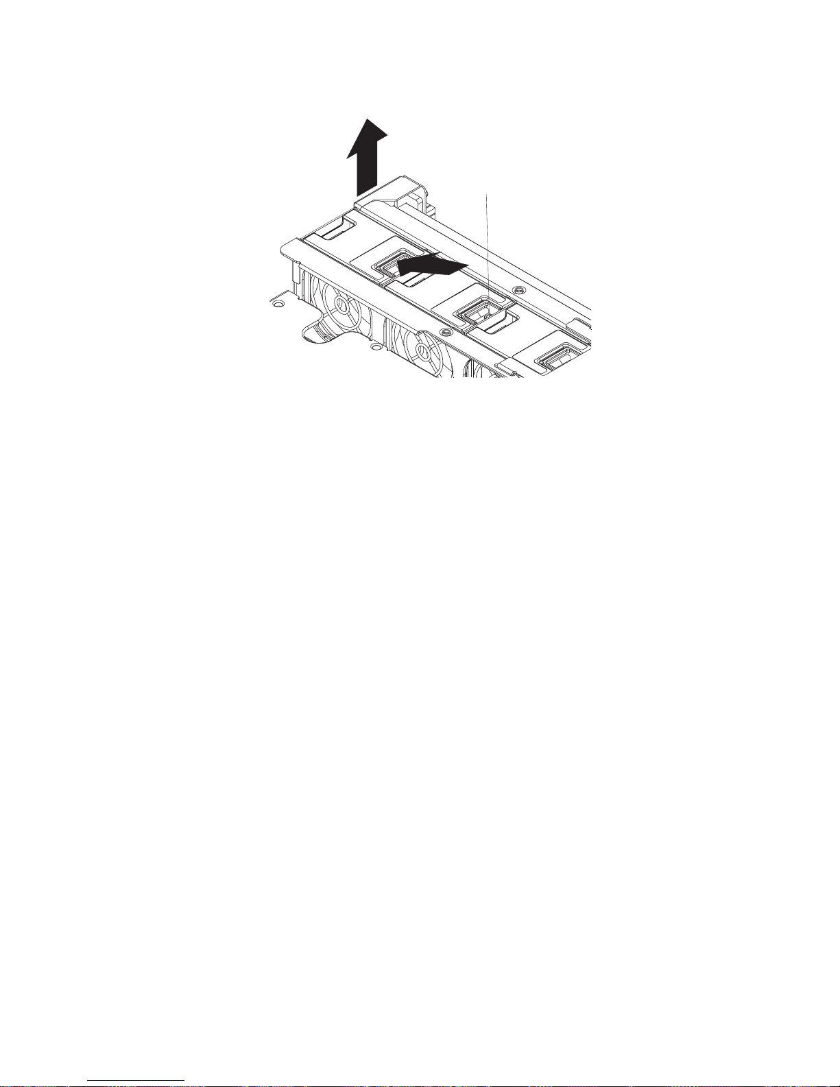
7. Press the fan-release latch in the direction indicated by the arrow.
Fan status LED
8. Pull the fan out of the server.
9. Align the two tabs on the replacement fan with the notches in the server and
press the fan into the corresponding connector. Press the fan firmly to engage
the latch fully and secure the fan in the server.
10. If the server is turned on, verify that the new fan is running and that its failure
LED is not lit. If the fan is not running or if its failure LED is lit, reseat the fan.
11. Replace the cover (see “Cover removal and replacement” on page 49).
Chapter 5. Service replaceable units 53
Page 64

Hot-swap power supply removal and replacement
Your server comes with two or three hot-swap power supplies. For servers with two
power supplies, you must turn off the server before replacing a power supply. For
servers with three power supplies, you do not need to turn off the server to replace
a hot-swap power supply, but you must replace only one power supply at a time.
Attention: Your server has hot-swap power supply capability only when three
power supplies are installed. In addition, your server has redundant power capability
only when three power supplies are installed.
If you install or remove a power supply, observe the following precautions.
Statement 8
CAUTION:
Never remove the cover on a power supply or any part that has the following label
attached.
Hazardous voltage, current, and energy levels are present inside any component that
has this label attached. There are no serviceable parts inside these components. If you
suspect a problem with one of these parts, contact a service technician.
Statement 12
CAUTION:
The following label indicates a hot surface nearby.
54 IBM eServer xSeries x382 Type 8834: Hardware Maintenance Manual and Troubleshooting Guide
Page 65

Complete the following steps to replace a hot-swap power supply:
1. Review the safety information beginning on page 95 and “Installation guidelines”
on page 43.
2. Remove the server bezel (see “Removing the bezel” on page 45).
3. If your server has only two power supplies installed, turn off the server (see
“Turning off the server” on page 9).
4. Press the orange release lever on the selected power supply; then, pull the
power supply out of the bay and set it aside.
Handle (open
position)
LED
Power supply
5. Make sure the power-supply handle is in the open position; then, slide the
power supply all the way into the chassis before placing the power-supply
handle into the locked position.
Power supply
blank cover
Handle (open
position)
LED
Power supply
6. If the server is not turned on, turn on the server (see “Turning on the server” on
page 8).
7. Verify that the ac power LEDs on the server and the PS dc power LEDs on
each power supply are lit, indicating that power supplies are installed and
operating properly.
8. Replace the server bezel (see “Replacing the bezel” on page 47).
Chapter 5. Service replaceable units 55
Page 66

Fan assembly and air baffle removal and replacement
Complete the following steps to remove the fan assembly and air baffle.
1. Review the “Safety information” on page 95 and “Installation guidelines” on
page 43.
2. Turn off the server and all attached devices, see “Turning off the server” on
page 9.
3. Disconnect all external cables and power cords.
4. Remove the cover (see “Cover removal and replacement” on page 49).
5. Remove the PCI riser assembly (see “PCI riser assembly removal and
replacement” on page 57).
6. Remove the four screws securing the air baffle.
7. Remove the screw securing the cable management plate on the fan bracket;
then, remove the cable management plate.
8. Disconnect the P1 cable from the front panel board, and the SCSI backplane
F2 cable from the SCSI backplane board. Lift the cables out of the cable
channel in the fan bracket and move them out of the way.
9. Remove the two screws from the cable channel.
10. Remove the fan at each end of the fan bracket (fans 1 and 6). See “Hot-swap
fan removal and replacement” on page 52.
11. Remove or loosen the screws (depending on the type of screw) holding the fan
bracket in place located:
v Beneath fans 1 and 6
v In the cable channel
v On the outside of the chassis, at each end of the fan bracket
Fan 1
Internal
captive
screws
Fan / peripheral
bay captive screw
External
captive screw
Cable
management
bracket
Fan 6
Cable
management
bracket screw
External
captive screw
12. Lift the fan bracket and air baffle together from the server and set them aside.
56 IBM eServer xSeries x382 Type 8834: Hardware Maintenance Manual and Troubleshooting Guide
Page 67

To replace the fan bracket and air baffle, reverse the previous steps.
PCI riser assembly removal and replacement
Complete the following steps to remove the PCI riser assembly:
1. Review the “Safety information” on page 95 and “Installation guidelines” on
page 43.
2. Turn off the server and all attached devices, see“Turning off the server” on
page 9.
3. Disconnect all external cables and power cords.
4. Remove the cover (see “Cover removal and replacement” on page 49).
5. Disconnect any internal cables that are attached to optional adapters.
6. Attention: To prevent damage to the PCI riser assembly connector and
system board connector, ensure that the four corners of the PCI riser assembly
are parallel to the system board and the connector on the PCI riser assembly
and system board are aligned before and while rotating the release lever.
Rotate the PCI riser assembly release lever in small 30 degree increments
stopping periodically to adjust the corners of the assembly to ensure that the
assembly is parallel to the system board. A full 90 degree rotation of the release
lever is required.
Rotate the PCI riser assembly release lever toward the rear of the server until it
stops.
Chapter 5. Service replaceable units 57
Page 68

7. Lift the PCI riser assembly straight up and away from the system board and
remove it from the server. Store the PCI riser in a safe place.
PCI riser assembly
PCI riser release
lever
58 IBM eServer xSeries x382 Type 8834: Hardware Maintenance Manual and Troubleshooting Guide
Page 69

The following illustration shows how to install the PCI riser in the server.
PCI riser assembly
PCI riser release
lever
Complete the following steps to replace the PCI riser assembly:
1. Place the PCI riser assembly release lever is in the extended position.
2. Insert the PCI riser assembly into the guides and press it down toward the
system board until it stops.
3. Attention: To prevent damage to the PCI riser assembly connector and
system board connector, ensure that the four corners of the PCI riser assembly
are parallel to the system board and the connector on the PCI riser assembly
and system board are aligned before and while rotating the release lever.
Rotate the PCI riser assembly release lever in small 30 degree increments
stopping periodically to adjust the corners of the assembly to ensure that the
assembly is parallel to the system board. A full 90 degree rotation of the release
lever is required.
Rotate the PCI riser assembly release lever toward the front of the server until it
stops.
4. Connect any internal cables that are required for optional adapters. Route
cables so that they do not block the flow of air from the fans.
5. Replace the cover (see “Cover removal and replacement” on page 49.
Chapter 5. Service replaceable units 59
Page 70

Adapter removal and replacement
Complete the following steps to remove an adapter from your server:
1. Review the “Safety information” on page 95 and “Installation guidelines” on
page 43.
2. Turn off the server and all attached devices (see “Turning off the server” on
page 9).
3. Disconnect all external cables and power cords.
4. Remove the cover (see “Cover removal and replacement” on page 49).
5. Remove the PCI riser assembly (see “PCI riser assembly removal and
replacement” on page 57).
Note: You might find it easier to remove the adapter if the PCI riser assembly is
on its side with the expansion slot facing up.
6. Release the adapter retention clip latch; then, open the adapter retention clip.
7. Grasp the adapter by the top edge or upper corners and slide it out of the slot.
Rear adapter
retainer
PCI Board 2
PCI Board 1
PCI Board 3
Front adapter
retainer
PCI Riser
Complete the following steps to replace an adapter in your server:
1. Review the “Safety information” on page 95 and “Installation guidelines” on
page 43.
2. Turn off the server and all attached devices.
3. Disconnect all power cords; then, disconnect all external cables.
4. Remove the cover (see “Cover removal and replacement” on page 49).
60 IBM eServer xSeries x382 Type 8834: Hardware Maintenance Manual and Troubleshooting Guide
Page 71

5. Remove the PCI riser assembly (see “PCI riser assembly removal and
replacement” on page 57).
Note: You might find it easier to install the adapter if the PCI riser assembly is
on its side with the expansion slot facing up.
6. Determine which slot you will use for the adapter. Check the instructions that
come with the adapter for any requirements, restrictions, or cabling
instructions.
7. Release the adapter retention clip latch; then, open the adapter retention clip.
Note: If you are installing a full-length adapter, there are adapter retention
clips at both ends of the adapter slot.
8. Grasp the expansion-slot cover and pull it out of the expansion slot. Store it in
a safe place for future use.
Note: Expansion-slot covers must be installed on all vacant slots. This
maintains the electronic emissions standards of the server and ensures
proper ventilation of server components.
9. Set any jumpers or switches on the adapter or system board according to the
documentation that comes with the adapter.
Attention: Avoid touching the components and gold-edge connectors on the
adapter.
10. If you are installing a full-length adapter, remove the blue adapter guide (if any)
from the end of the adapter.
Attention: Be certain that the adapter is correctly seated in the expansion
slot. Incomplete installation of an adapter might damage the system board or
the adapter.
11. Carefully grasp the adapter by the top edge or upper corners, and align it with
the expansion slot guides; then, press the adapter firmly into the expansion
slot. Move the adapter directly from the static-protective package to the
adapter slot.
Adapter guide
Chapter 5. Service replaceable units 61
Page 72

Rear adapter
retainer
PCI Board 2
PCI Board 1
PCI Board 3
Front adapter
retainer
PCI Riser
12. If you have another adapter to install, repeat steps 6 through 11 on page 61.
Otherwise, close the adapter-retention clip over the top corner of the adapter.
Make sure the adapter-retention clip latch is in the locked (closed) position.
Note: If you are installing a full-length adapter, there are adapter retention
clips at both ends of the adapter slot.
13. If you have other options to install, do so now; otherwise, continue with step
14.
14. Replace the PCI riser assembly (see “PCI riser assembly removal and
replacement” on page 57).
15. Replace the cover (see “Cover removal and replacement” on page 49).
16. Reconnect the external cables and power cords; then, turn on the attached
devices and the server.
62 IBM eServer xSeries x382 Type 8834: Hardware Maintenance Manual and Troubleshooting Guide
Page 73

Memory DIMMs removal and replacement
Complete the following steps to remove and replace memory DIMMs.
Important: Memory is 4-way interleaved and must be populated in sets consisting
of identical type/size DIMMs.
Complete the following steps to remove a DIMM:
1. Review the “Safety information” on page 95 and “Installation guidelines” on
page 43.
2. Turn off the server and disconnect all power cords and external cables; then,
remove the cover (see “Cover removal and replacement” on page 49).
3. Remove the PCI riser assembly (see “PCI riser assembly removal and
replacement” on page 57).
4. Locate the DIMM connectors on the system board. Determine the DIMM that
you want to replace.
5. Open the retaining clips and remove the existing DIMM.
Complete the following steps to replace a DIMM:
1. Review the “Safety information” on page 95 and “Installation guidelines” on
page 43.
2. Turn off the server and disconnect all power cords and external cables; then,
remove the cover (see “Cover removal and replacement” on page 49).
3. Remove the PCI riser assembly (see “PCI riser assembly removal and
replacement” on page 57).
4. Locate the DIMM connectors on the system board. Determine the connectors
into which you will install the DIMMs.
5. Open the retaining clips, if necessary, remove any existing DIMMs.
Chapter 5. Service replaceable units 63
Page 74

6. Touch the static-protective package containing the DIMM to any unpainted
metal surface on the server; then, remove the new DIMM from the package.
7. Gently open the retaining clip on each end of the DIMM slot. Turn the DIMM
so that the pins align correctly with the connector.
8. Insert the DIMM into the connector. Firmly press the DIMM straight down into
the connector by applying pressure on both ends of the DIMM simultaneously.
The retaining clips snap into the locked position when the DIMM is firmly
seated in the connector. If there is a gap between the DIMM and the retaining
clips, the DIMM has not been correctly installed. Open the retaining clips,
remove the DIMM, and then reinsert it.
DIMM 4
DIMM 3
DIMM 2
DIMM 1
9. If you have other options to install or remove, do so now.
10. Replace the PCI riser assembly (see “PCI riser assembly removal and
replacement” on page 57).
11. Replace the cover (see “Cover removal and replacement” on page 49).
12. Reconnect the external cables and power cords. Turn on the attached devices,
and turn on the server.
64 IBM eServer xSeries x382 Type 8834: Hardware Maintenance Manual and Troubleshooting Guide
Page 75
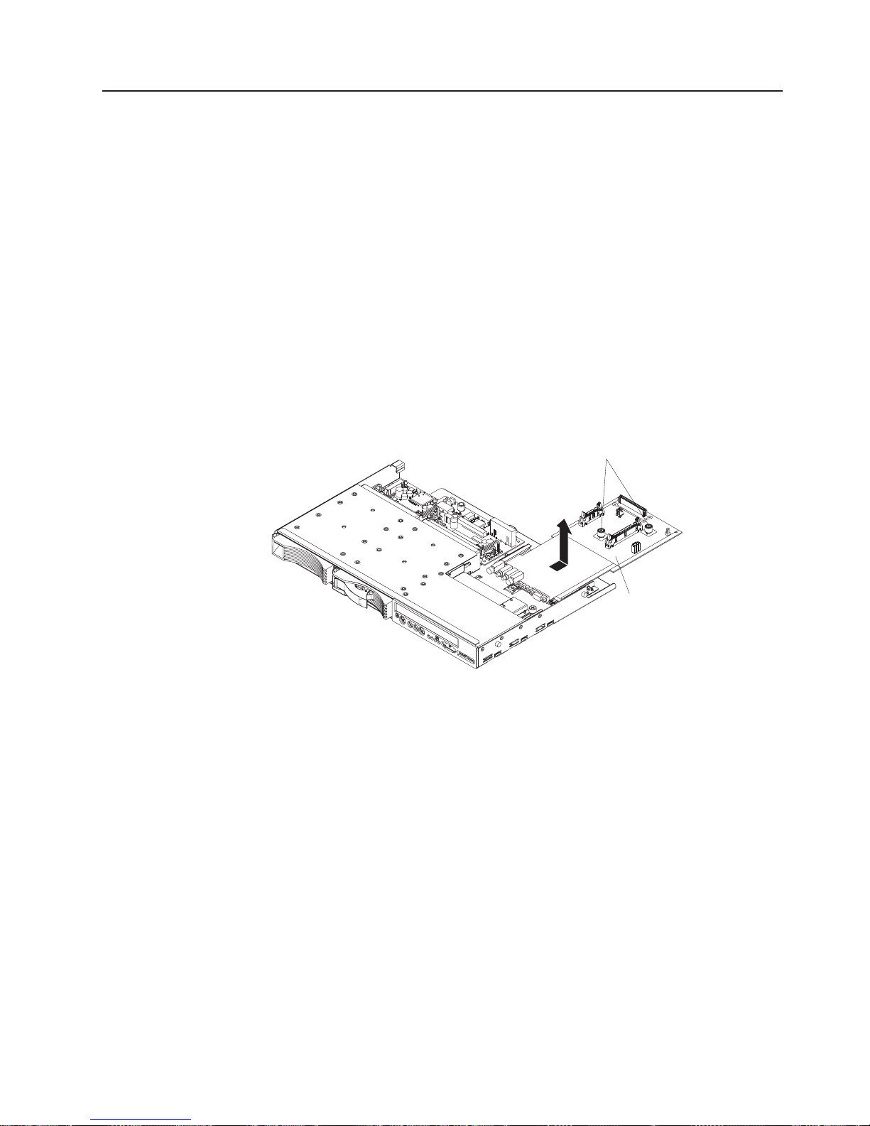
Front panel board removal and replacement
Complete the following steps to remove the front panel board.
1. Review the “Safety information” on page 95 and “Installation guidelines” on
page 43.
2. Turn off the server and all attached devices (see “Turning off the server” on
page 9).
3. Remove the cover (see “Cover removal and replacement” on page 49).
4. Disconnect all external cables and power cords.
5. Disconnect the cables from the rear of the CD-ROM drive and move them
aside.
6. Disconnect the cables from connectors J2B1 and J1D1 on the front panel board
and move them out of the way.
7. Loosen the two thumb screws holding the front panel board in place.
8. Slide the front panel board toward the rear of the server as far as it will go.
9. Loosen the thumb screw holding the CD-ROM tray in place; then, slide the
CD-ROM assembly toward the rear of the server and lift the assembly out of the
server.
Thubm screws
Front panel
board
To install the replacement front panel board, reverse the previous steps.
Chapter 5. Service replaceable units 65
Page 76

SCSI backplane removal and replacement
Complete the following steps to remove the front panel board.
1. “Safety information” on page 95 and “Installation guidelines” on page 43.
2. Turn off the server and all attached devices, see“Turning off the server” on
page 9.
3. Disconnect all external cables and power cords.
4. Remove the cover (see “Cover removal and replacement” on page 49).
5. Remove all hard disk drives from the drive bays.
6. Remove the screw securing the cable retainer on the fan bracket; then,
remove the cable retainer.
7. Disconnect all cables from the SCSI backplane.
8. Remove the three screws holding the SCSI backplane in place.
SCSI backplane Thumb screws
Guide pins (4)
9. Slide the SCSI backplane toward the front panel board about 0.6 cm (0.2 in.)
until it stops.
10. Lift the SCSI backplane out of the server.
To replace the SCSI backplane, align the three keyhole-shaped slots with the three
cylindrical pins on the peripheral module; then, reverse the steps for removing the
SCSI backplane.
66 IBM eServer xSeries x382 Type 8834: Hardware Maintenance Manual and Troubleshooting Guide
Page 77

Peripheral bay removal and replacement
Complete the following steps to remove the peripheral bay:
1. “Safety information” on page 95 and “Installation guidelines” on page 43.
2. Turn off the server and all attached devices (see “Turning off the server” on
page 9).
3. Disconnect all external cables and power cords.
4. Remove the cover (see “Cover removal and replacement” on page 49).
5. Disconnect the P1 cable from the front panel board, the SCSI backplane F2
cable and power cables from the SCSI backplane board
6. Loosen the single screw on the rear of the peripheral bay (near the center of
the fan assembly).
7. Slide the peripheral bay toward the front of the server as far as it will go
(approximately 1-inch), lift it straight up and remove it from the server.
Peripheral bay
8. Place the peripheral bay on a clean, static-free work space.
To replace the peripheral bay, reverse the previous steps.
Chapter 5. Service replaceable units 67
Page 78

Power supply bay removal and replacement
Complete the following steps to remove the power supply bay:
1. “Safety information” on page 95 and “Installation guidelines” on page 43.
2. Turn off the server and all attached devices (see “Turning off the server” on
page 9).
3. Disconnect all external cables and power cords.
4. Remove the cover (see “Cover removal and replacement” on page 49).
5. Remove the hot-swap power supplies (see “Power pod removal and
replacement” on page 75).
6. Remove the screw securing the cable management plate from the center of
the fan assembly.
7. Disconnect the P1 cable from the front panel board, the SCSI backplane F2
cable and power cable from the SCSI backplane board and move them out of
the way.
8. Loosen the retaining screw on the peripheral bay.
9. Slide the peripheral bay toward the front of the server, lift up and remove it
from the server.
10. Remove the fan assembly and air baffle (see “Fan assembly and air baffle
removal and replacement” on page 56).
11. Loosen the two screws (located near memory slot 1 and the ac power
connector) at the back of the chassis that secures the Electronics bay. Slide
the Electronics bay toward the rear of the server (approximately 1-inch) to
access and loosen the three retention screws at the rear of the power supply
bay.
12. Loosen the two screws on top of the power supply bay.
13. Lift up the power supply bay and remove it from the server.
Screws
Power supply bay
68 IBM eServer xSeries x382 Type 8834: Hardware Maintenance Manual and Troubleshooting Guide
Page 79

Complete the following steps to replace the power supply bay:
1. Remove the hot-swap power supplies from the power supply bay.
2. Slide the power supply bay in from the front of the server.
3. Align and tighten the three retention screws at the rear of the power supply
bay.
4. Replace the two screws on top of the power supply bay.
5. Slide the Electronics bay toward the rear of the chassis as far as it will go;
then, tighten the two screws at the rear of the chassis to secure the
Electronics bay.
6. Place the peripheral bay assembly on top of the power supply bay and slide
the peripheral bay toward the rear of the server as far as it will go; then,
tighten the retaining screw at the rear of the peripheral bay to secure it.
7. Reconnect all cables that were disconnected.
8. Reinstall the fan assembly.
9. Reattach the cable management plate to the fan assembly.
10. Install the fans in the fan bay. Align the two tabs on the replacement fan with
the notches in the server and press the fan into the corresponding connector.
Press the fan firmly to engage the latch fully and secure the fan in the server.
11. Reinstall the power supplies.
12. Replace the cover (see “Cover removal and replacement” on page 49).
Chapter 5. Service replaceable units 69
Page 80

System board removal and replacement
Complete the following steps to remove the system board:
1. Review the “Safety information” on page 95 and “Installation guidelines” on
page 43.
2. Turn off the server and all attached devices, see“Turning off the server” on
page 9.
3. Disconnect all external cables and power cords.
4. Remove the cover (see “Cover removal and replacement” on page 49.
5. Remove the PCI riser assembly, see “PCI riser assembly removal and
replacement” on page 57.
6. Remove the fan assembly and air baffle, see “Fan assembly and air baffle
removal and replacement” on page 56.
7. Remove the power pods, see “Power pod removal and replacement” on
page 75.
8. Remove a microprocessor, see “Microprocessor removal and replacement” on
page 74.
9. Remove the memory DIMMs, see “Memory DIMMs removal and replacement”
on page 63.
10. Loosen the screw at the rear of the chassis, which secures the retention lever
assembly.
Interlock tabs
Captive screw
70 IBM eServer xSeries x382 Type 8834: Hardware Maintenance Manual and Troubleshooting Guide
Page 81
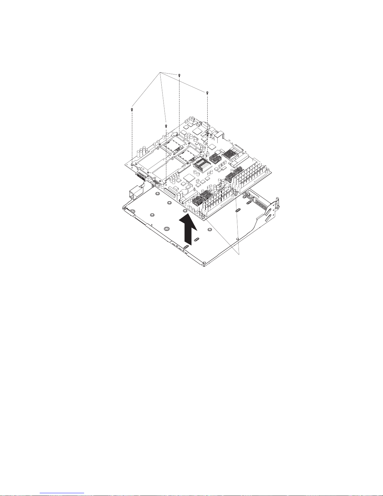
11. Lift the system board from the rear and disengage the interlock tabs at the
front; then, remove the system board.
Hex screws (4)
Captive screws
(2)
To replace the system board, reverse the previous steps.
Note: To update the programmed system serial number run the BIOS/Firmware
update utility. For latest BIOS/Firmware go to
http://www.ibm.com/pc/support/.
Chapter 5. Service replaceable units 71
Page 82

System board componets
12 3 456
7
8 9 10 11 12 13 14
1. Microprocessor 1 (required)
2. Microprocessor 2 (optional)
3. Video connector
4. USB 0 (bottom) and USB 1 (top) connectors
5. Serial connector
6. LAN 1 (bottom) and LAN 2 (top) connector
7. System ID LED
8. System ID button
9. External SCSI connector
10. VHDM connectors (for PCI riser)
11. DIMM connector 8
12. DIMM connector 4
13. DIMM connector 7
14. DIMM connector 3
15. DIMM connector 1
16. DIMM connector 5
17. DIMM connector 2
18. DIMM connector 6
19. Battery
20. Internal SCSI connector
21. IDE/USB/FP connector
22. Power pod power connector
23. Power module 2
24. DC docking connector
25. Power module 1
1516171819202122232425
72 IBM eServer xSeries x382 Type 8834: Hardware Maintenance Manual and Troubleshooting Guide
Page 83

System board jumpers
There are nine jumper blocks called out on the main board.
12 34
Table 13.
Index Jumper Signal / Description
1 J1A1 (RSRL_MODE0) Used to set Serial Port mode. Default is 1-2 on both.
2 J1A2 (RSRL_MODE1) Used to set Serial Port mode. Default is 1-2 on both.
3 J3A3 (SMM_BB_UNPROT_L) Jumper 2-3 to enable programming of the
4 J3B1 (JTAG chain TDI/TDO) JTAG signal routing. Default is 3-4, 5-6, and
5 J5H4 BMC Force Update Pin 1-2 default.
6 J5H3 Clear CMOS Pin 1-2 default. Move to 2-3 position to clear.
7 J5H2 Clear password. Move to 2-3 position to clear.
8 J5H1 RCV Boot (Recovery) Pin 1-2 default. Move to 2-3 position for
9 J6G2 (FWH20_ID1_SWAP_L) Swaps North Bridge FWH ID0 and ID2.
5
7
6
89
BMC boot block. Default is 1-2.
7-8 to include SNC-M, SIOH (on the PCI riser board), microprocessor
2, then microprocessor 1.
recovery mode.
Chapter 5. Service replaceable units 73
Page 84

Microprocessor removal and replacement
Complete the following steps to remove a microprocessor:
1. Review the “Safety information” on page 95 and “Installation guidelines” on
page 43.
2. Turn off the server and all attached devices, see“Turning off the server” on
page 9.
3. Disconnect all external cables and power cords.
4. Remove the cover (see “Cover removal and replacement” on page 49).
5. Determine the microprocessor you want to replace.
6. Remove the power pod that is associated with the microprocessor you want to
replace (see “Power pod removal and replacement” on page 75).
7. Loosen the four captive screws on the microprocessor.
8. Use a 2.5 mm hex driver to rotate the microprocessor release mechanism 90
degrees counter-clockwise to release the microprocessor’s pins; then, lift the
microprocessor out of its socket.
Note: After the microprocessor is removed and if you are not installing another
microprocessor, use a 2.5 mm hex driver to rotate the release
mechanism clockwise to the closed position.
Air baffle
180°
9. To replace a microprocessor, reverse the previous steps.
74 IBM eServer xSeries x382 Type 8834: Hardware Maintenance Manual and Troubleshooting Guide
Page 85

Power pod removal and replacement
Complete the following steps to remove a power pod:
1. Review the “Safety information” on page 95 and “Installation guidelines” on
page 43.
2. Turn off the server and all attached devices (see, “Turning off the server” on
page 9).
3. Disconnect all external cables and power cords.
4. Remove the cover (see “Cover removal and replacement” on page 49).
5. Remove the fan assembly and air baffle (see “Fan assembly and air baffle
removal and replacement” on page 56).
6. Disconnect the Y-cable from the power pod that you want to remove by
releasing the connector.
7. Loosen the four captive screws on the power pod; then, slide the power pod
away from the microprocessor to disengage the power pod from its connector.
Air baffle
180°
8. Lift the power pod out of the server.
To replace a power pod, reverse the previous steps.
Chapter 5. Service replaceable units 75
Page 86

System battery
This section describes how to remove and replace the system battery.
Battery removal and replacement
IBM has designed this product with your safety in mind. The lithium battery must be
handled correctly to avoid possible danger. If you replace the battery, you must
adhere to the following instructions.
Note: In the U. S., call 1-800-IBM-4333 for information about battery disposal.
If you replace the original lithium battery with a heavy-metal battery or a battery with
heavy-metal components, be aware of the following environmental consideration.
Batteries and accumulators that contain heavy metals must not be disposed of with
normal domestic waste. They will be taken back free of charge by the manufacturer,
distributor, or representative, to be recycled or disposed of in a proper manner.
To order replacement batteries, call 1-800-772-2227 within the United States, and
1-800-465-7999 or 1-800-465-6666 within Canada. Outside the U.S. and Canada,
call your IBM reseller or IBM marketing representative.
Note: After you replace the battery, you must reconfigure your server and reset the
system date and time.
Statement 2
CAUTION:
When replacing the lithium battery, use only IBM Part Number 33F8354 or an
equivalent type battery recommended by the manufacturer. If your system has a
module containing a lithium battery, replace it only with the same module type made
by the same manufacturer. The battery contains lithium and can explode if not
properly used, handled, or disposed of.
Do not:
v Throw or immerse into water
v Heat to more than 100°C (212°F)
v Repair or disassemble
Dispose of the battery as required by local ordinances or regulations.
Complete the following steps to remove the battery:
1. Review the “Safety information” on page 95 and “Installation guidelines” on
page 43.
2. Follow any special handling and installation instructions supplied with the
replacement battery.
3. Turn off the server and all attached devices.
4. Disconnect all power cords; then, disconnect all external cables.
5. Remove the cover (see “Cover removal and replacement” on page 49 and “PCI
riser assembly removal and replacement” on page 57).
6. Remove the battery:
a. Use a fingernail to pop the battery up.
76 IBM eServer xSeries x382 Type 8834: Hardware Maintenance Manual and Troubleshooting Guide
Page 87

b. Use your thumb and index finger to lift the battery from the socket.
7. Insert the new battery:
a. Tilt the battery so that you can insert it into the socket.
b. Press the battery down into the socket until it clicks into place.
8. Replace the PCI riser assembly and replace the cover. (See “Cover removal
and replacement” on page 49 and “Cover removal and replacement” on
page 49.)
9. Connect all external cables; then, connect the power cords.
10. Turn on the server.
11. Start the Configuration/Setup Utility program and set configuration parameters
as needed. See the User’s Guide on the IBM xSeries Documentation CD.
Chapter 5. Service replaceable units 77
Page 88

78 IBM eServer xSeries x382 Type 8834: Hardware Maintenance Manual and Troubleshooting Guide
Page 89

Chapter 6. Symptom-to-FRU index
This index supports the eServer xSeries x382 Type 8834.
Notes:
1. Check the configuration before you replace a FRU. Configuration problems can
cause false errors and symptoms.
2. For IBM devices not supported by this index, refer to the manual for that device.
3. Always start with “General checkout” on page 21.
The symptom-to-FRU index lists symptoms, errors, and the possible causes. The
most likely cause is listed first. Use this symptom-to-FRU index to help you decide
which FRUs to have available when servicing the server.
The left-hand column of the tables in this index lists error codes or messages, and
the right-hand column lists one or more suggested actions or FRUs to replace.
Note: In tables with more than two columns, multiple columns are required to
describe the error symptoms.
Take the action (or replace the FRU) suggested first in the list of the right-hand
column, then try the server again to see if the problem has been corrected before
taking further action.
Note: Try reseating a suspected component or reconnecting a cable before
replacing the component.
The POST BIOS code displays POST error codes and messages on the screen.
Beep codes
During POST, problems can occur before video is enabled. These errors are
conveyed by encoded beeps, coupled with POST debug codes.
Table 14. Beep codes
Note: See “System” on page 92 to determine which components should be replaced by a field service technician.
Beeps Description
3 (Memory failure) See “Memory” on page 32.
4 (System Timer) See “Microprocessor debug methodology:” on page 33 If symptom
persists replace system board.
5 (Microprocessor Failure) See “Microprocessor debug methodology:” on page 33.
7 (Microprocessor exception interrupt
error)
8 (Display memory read/write error) Check Add-in video adapter if used, if onboard is used video DRAM
9 (ROM Checksum error) Corrupted BIOS, Clear CMOS or perform BIOS recovery see, “Clearing
11 (Invalid BIOS) Corrupted BIOS, Clear CMOS or perform BIOS recovery see, “Clearing
See “Microprocessor debug methodology:” on page 33.
may be failing, replace system board.
CMOS” on page 41and “BIOS recovery mode” on page 42.
CMOS” on page 41and “BIOS recovery mode” on page 42.
© Copyright IBM Corp. 2002 79
Page 90

Recovery beep codes
Table 15. Recovery beep codes
Note: See “System” on page 92 to determine which components should be replaced by a field service technician.
Beeps Description
1 short - medium tone Medium tone BIOS flash update started.
2 short - medium tone Medium tone BIOS flash update complete.
Repeating - low tone Low tone BIOS recovery error occurred, or no
recovery media found.
BMC generated beep codes
Note: See “System” on page 92 to determine which components should be replaced by a field service technician.
Beep code Description
1-5-1-1 See “Microprocessor debug methodology:” on page 33 and “FRB FRU isolation” on
page 37.
1-5-2-1 No processor found in socket 1, See “Microprocessor debug methodology:” on page 33 and
“FRB FRU isolation” on page 37.
1-5-2-2 No processor found in socket 1, See “Microprocessor debug methodology:” on page 33 and
“FRB FRU isolation” on page 37.
1-5-2-3 General Microprocessor Issue, See “Microprocessor debug methodology:” on page 33 and
“FRB FRU isolation” on page 37.
1-5-4-2 (DC
voltage error)
1-5-4-3 (Chipset
control failure)
1-5-4-4 (Voltage
error, or dead short
(MOST Common
cause) i.e. DC to
GND)
1. Check TPS power supplies for amber lights - replace if found.
2. Check / replace the power cage.
Chipset control failure.
1. Check the TPS power supplies for amber lights, replace if found.
2. Check Flex Cable for damage (nick in housing) or poor connection. Reseat tor replace the
cable. Check all board to board connections i.e. VHDM connectors (riser to system board)
carefully look for bent or flattened pins at end of connector near fans.
3. Check / replace power cage.
80 IBM eServer xSeries x382 Type 8834: Hardware Maintenance Manual and Troubleshooting Guide
Page 91

Error codes - video display
The system BIOS displays POST error messages on the video screen. POST error
codes are logged in the SEL. The following table defines POST error codes and
their associated messages. The xSeries 382 BIOS prompt you to press a key in
case of serious errors.
Some errors are displayed on the screen in red text. These are critical events that
require user interaction and the BIOS POST pauses awaiting user input, prompting
with a message requesting Press F1, F2, or ESC. This error code type is indicated
in the table below as a Yes in the column heading Pause On Boot. This type of
error causes the system to pause during system boot. Pausing for user interaction
can be overridden in BIOS Setup.
Other error codes are displayed on the screen in yellow. These errors are
non-critical and are displayed briefly during POST. These errors are also logged to
the SEL. This error code type is indicated in the table below as a No in the column
heading Pause On Boot.
Table 16. Error codes/messages
Error code FRU/action
103 (CMOS Battery Failure) Yes
104 (CMOS Options not Set) Yes
105 (CMOS Checksum Failure) Yes
109 (Keyboard Stuck Key) Yes
11B (Date/Time Not Set) Yes
120 (CMOS clear) Yes
121 (Password clear) Yes
122 (NVRAM cleared by front
panel)
Yes
1. Check the battery.
2. Run Setup.
3. Replace the system board.
1. Check the battery.
2. Run Setup.
3. Replace the system board.
1. Check the battery.
2. Run Setup.
3. Replace the system board.
1. Check for stuck key.
2. Replace the keyboard.
3. Replace the system board.
1. Check the battery.
2. Set the date and time.
3. Replace the system board.
1. Check the clear CMOS jumper J5H3: Normal 1-2,
Clear 2-3.
2. Replace the system board.
1. Check the clear password jumper J5H2: Normal 1-2,
Clear 2-3.
2. Replace the system board.
1. CMOS has been cleared by front panel control
sequence. See, “Clearing CMOS” on page 41and “BIOS
recovery mode” on page 42.
2. Replace the front panel.
3. Replace the system board.
Chapter 6. Symptom-to-FRU index 81
Page 92

Table 16. Error codes/messages (continued)
Error code FRU/action
140 (PCI error) Yes
141 (PCI memory allocation error) Yes.
142 (PCI IO allocation error) Yes
143 (PCI IRQ allocation error) Yes
0144 (Shadow of PCI ROM failed) Yes
145 (PCI ROM not found) Yes
146 (Insufficient memory to shadow
PCI ROM)
8100 (Microprocessor 01 failed
BIST)
Yes
Yes Microprocessor failed to initialize in time, Refer to ″Fault
1. Check the PCI riser card connectors for pin damage.
2. Reseat the PCI adapters and retest the server.
Note: The PCI riser card contains core logic and must
be installed to boot the server.
3. Replace the riser card.
4. Replace the system board.
1. Memory allocation area for PCI device exceeded.
Remove any add-in PCI adapters and retest the
server.
2. Replace any PCI add-in adapters
3. Replace the PCI riser card.
4. Replace the system board.
1. PCI IO resource allocation for PCI device has been
exceeded. Remove any add-in PCI adapters and
retest the server.
2. Replace any PCI add-in adapters
3. Replace the PCI riser card.
4. Replace the system board.
1. PCI IRQ allocation for PCI devices has been
exceeded. Remove any add-in PCI adapters and
retest the server.
2. Replace any PCI add-in adapters
3. Replace the PCI riser card.
4. Replace the system board.
1. PCI ROM memory allocation area for PCI devices has
been exceeded. Remove any add-in PCI adapters and
retest the server.
2. Replace any PCI add-in adapters
3. Replace the PCI riser card.
4. Replace the system board.
1. PCI ROM memory allocation area for PCI devices has
been exceeded or PCI ROM did not have space to
load. Remove any add-in PCI adapters and retest the
server.
2. Replace any PCI add-in adapters
3. Replace the PCI riser card.
4. Replace the system board.
1. PCI ROM area exceeded. Remove any add-in PCI
adapters and retest the server.
2. Replace any PCI add-in adapters
3. Replace the PCI riser card.
4. Replace the system board.
Resilient Boot″ in Debug Methodology and FRU Isolation
section.
82 IBM eServer xSeries x382 Type 8834: Hardware Maintenance Manual and Troubleshooting Guide
Page 93

Table 16. Error codes/messages (continued)
Error code FRU/action
8101 (Microprocessor 02 failed
BIST)
Yes Microprocessor failed to initialize in time, Refer to ″Fault
Resilient Boot″ in Debug Methodology and FRU Isolation
section.
8110 (Microprocessor 01 internal
error (IERR)
8111 (Microprocessor 02 internal
error (IERR)
8120 (Microprocessor 01: Thermal
trip failure)
Yes Refer to ″Microprocessor″ in Debug Methodology and
FRU Isolation section. .
Yes Refer to ″Microprocessor″ in Debug Methodology and
FRU Isolation section.
Yes Microprocessor 01 has exceeded the thermal diode
temperature limit resulting in a thermal trip event, check
for airflow obstructions to fans & heat sinks. Ensure
processor air duct is present and secured. The system
is designed to run heavy loads up to 35C or 96F
ambient. However, Under normal (i.e. no fan failure)
conditions, the CPU should not throttle until 42C/ 107F.
(With a fan failure, throttling could possibly occur at
about 27C) Thermal trip should occur at 50C /120F,
thermal trip will shut down the processor or system. If
this occurs and the ambient temp is far cooler - Refer to
″Microprocessor″ in Debug Methodology and FRU
Isolation section .
8121 (Microprocessor 02: Thermal
trip failure)
Yes Microprocessor 02 has exceeded the thermal diode
temperature limit resulting in a thermal trip event, check
for airflow obstructions to fans & heat sinks. Ensure
processor air duct is present and secured. The system
is designed to run heavy loads up to 35C or 96F
ambient. However, Under normal (i.e. no fan failure)
conditions, the CPU should not throttle until 42C/ 107F.
(With a fan failure, throttling could possibly occur at
about 27C) Thermal trip should occur at 50C /120F,
thermal trip will shut down the processor or system. If
this occurs and the ambient temp is far cooler - Refer to
″Microprocessor″ in Debug Methodology and FRU
Isolation section.
8130 (Microprocessor 01 disabled) Yes Microprocessor failed to initialize in time, Refer to Refer
to ″Fault Resilient Boot″ in Debug Methodology and FRU
Isolation section.
8131 (Microprocessor 02 disabled) Yes Microprocessor failed to initialize in time, Refer to Refer
to ″Fault Resilient Boot″ in Debug Methodology and FRU
Isolation section.
8140 (Microprocessor 01 failed FRB
level 3 timer)
Yes Microprocessor failed: Fault Resilient Boot Timer (FRB)
expired. Refer to Refer to ″Fault Resilient Boot″ in Debug
Methodology and FRU Isolation section.
8141 (Microprocessor 02 failed FRB
level 3 timer)
Yes Microprocessor failed: Fault Resilient Boot Timer (FRB)
expired. Refer to Refer to ″Fault Resilient Boot″ in Debug
Methodology and FRU Isolation section.
8150 (Microprocessor 01 failed
initialization on last boot)
Yes Microprocessor failed to initialize in time, Refer to Refer
to ″Fault Resilient Boot″ in Debug Methodology and FRU
Isolation section.
8151 (Microprocessor 02 Failed
initialization on last boot)
Yes Microprocessor failed to initialize in time, Refer to Refer
to ″Fault Resilient Boot″ in Debug Methodology and FRU
Isolation section.
Chapter 6. Symptom-to-FRU index 83
Page 94

Table 16. Error codes/messages (continued)
Error code FRU/action
8192 (L3 cache size mismatch) Yes BIOS compared Microprocessors & determined an L3
cache mismatch; both processors should run with
different cache sizes. If both processors are identical Refer to ″Microprocessor″ in Debug Methodology and
FRU Isolation section.
8193 (CPUID, Microprocessor
Stepping levels are different)
8196 (Microprocessor models are
different)
8197 (Microprocessor speed
mismatched
8210 (Microprocessor 01 late self
test failed: Performance restricted)
8211 (Microprocessor 02 late self
test failed: Performance restricted)
8220 (Microprocessor 01 late self
test failed: Functionally restricted)
8221 (Microprocessor 02 late self
test failed: Functionally restricted)
8230 (Microprocessor 1 late self
test failed: Catastrophic failure)
8231 (Microprocessor 2 late self
test failed: Catastrophic failure)
8300 (Baseboard management
controller (BMC) failed to function)
Yes BIOS compared Microprocessors & determined a
mismatch, both processors may run - If different speeds
they will be Performance restricted, both will run at
lower of the two speeds, If incompatible - one processor
may be disabled. Check stepping & P/N information Dissimilar stepping processors are not supported. Refer
to ″Microprocessor″ in Debug Methodology and FRU
Isolation section.
Yes BIOS compared Microprocessors & determined a
mismatch, both processors may run - If different speeds
they will be Performance restricted, both will run at
lower of the two speeds, If incompatible - one processor
may be disabled. Check stepping & P/N information Dissimilar stepping & mixed family processors are not
supported. Refer to “Microprocessor” in Debug
Methodology and FRU Isolation section.
Yes BIOS compared Microprocessors & determined
mismatched speeds, both processors will be
Performance restricted, both will default to run at lower
of the two speeds. If both processors are identical Refer to “Microprocessor” in Debug Methodology and
FRU Isolation section.
Yes Failure identified in late self-test, Microprocessor 1 will
be Performance restricted. Refer to “Microprocessor
Late Self test” in Debug Methodology and FRU Isolation
section.
Yes Failure identified in late self-test, Microprocessor 2 will
be Performance restricted. Refer to “Microprocessor
Late Self test” in Debug Methodology and FRU Isolation
section.
Yes Failure identified in late self-test, Microprocessor 1 will
be Functionally restricted. Refer to “Microprocessor Late
Self test” in Debug Methodology and FRU Isolation
section.
Yes Failure identified in late self-test, Microprocessor 2 will
be Functionally restricted. Refer to “Microprocessor Late
Self test” in Debug Methodology and FRU Isolation
section.
Yes Failure identified in late self-test, Microprocessor 1 will
be disabled. Refer to “Microprocessor Late Self test” in
Debug Methodology and FRU Isolation section.
Yes Failure identified in late self-test, Microprocessor 1 will
be disabled. Refer to “Microprocessor Late Self test” in
Debug Methodology and FRU Isolation section.
Yes
1. Check to see that the jumper at J5H4 is in position
1-2 =normal, (position 2-3 is update mode).
2. Replace the system board
84 IBM eServer xSeries x382 Type 8834: Hardware Maintenance Manual and Troubleshooting Guide
Page 95

Table 16. Error codes/messages (continued)
Error code FRU/action
8306 (OS boot watchdog timer
failure)
Yes System exceeded 6-minute watchdog timer on boot
cycle. Refer to “Watch dog timer” for details.
84F3 (BMC in Update Mode) Yes Check to see that the jumper at J5H4 is in position 1-2
=normal, (position 2-3 is update mode).If Issue persists
replace Minipark.
84FF (System event log full) Yes The System Event Log is Full, Save or Clear SEL, See
section on “Thresholding”
8500 (Multi-bit error detected in row
1. Row 1 mapped out)
Yes The multi-bit error is detected on a DIMM(s) in Row 1;
Row disabled, Refer to “Memory” in Debug Methodology
and FRU Isolation section.
8501 (Multi-bit error detected in row
2. Row 2 mapped out)
Yes The multi-bit error is detected on a DIMM(s) in Row 2;
Row disabled, Refer to “Memory” in Debug Methodology
and FRU Isolation section.
8504 (Persistent single-bit error
detected Row 1. Row 1 mapped
out)
Yes Issue with DIMM address or data line likely affecting
multiple DIMMs (otherwise ECC should recover) in Row
1; Row disabled, Refer to “Memory” in Debug
Methodology and FRU Isolation section.
8505 (Persistent single-bit error
detected in row 2. Row 2 mapped
out)
Yes Issue with DIMM address or data line likely affecting
multiple DIMMs (otherwise ECC should recover) in Row
2; Row disabled, Refer to “Memory” in Debug
Methodology and FRU Isolation section.
8508 (Memory mismatch detected
in row 1. Row 1 mapped out
Yes Issue with DIMM SPD value in Row 1; Row disabled,
Refer to “Memory” in Debug Methodology and FRU
Isolation section.
8509 (Memory mismatch detected
in row 2. Row 2 mapped out)
Yes Issue with DIMM SPD value in Row 2; Row disabled,
Refer to “Memory” in Debug Methodology and FRU
Isolation section.
850C (DIMM 1 defective) Yes Issue with DIMM 1=J9J3, Refer to “Memory” in Debug
Methodology and FRU Isolation section.
850D (DIMM 2 defective) Yes Issue with DIMM 2=J9J1, Refer to “Memory” in Debug
Methodology and FRU Isolation section.
850E (DIMM 3 defective) Yes Issue with DIMM 3=J9D3, See memory in Debug
Methodology and FRU Isolation section.
850F (DIMM 4 defective) Yes Issue with DIMM 4=J9D1, See memory in Debug
Methodology and FRU Isolation section.
8510 (DIMM 5 defective) Yes Issue with DIMM 5=J9J2, See memory in Debug
Methodology and FRU Isolation section.
8511 (DIMM 6 defective) Yes Issue with DIMM 6=J8J1, See memory in Debug
Methodology and FRU Isolation section.
8512 (DIMM 7 defective) Yes Issue with DIMM 7=J9J2, See memory in Debug
Methodology and FRU Isolation section.
8513 (DIMM 8 defective) Yes Issue with DIMM 8=J8D1, See memory in Debug
Methodology and FRU Isolation section.
Chapter 6. Symptom-to-FRU index 85
Page 96

Error symptoms
You can use the error symptom table to find solutions to problems that have definite
symptoms.
If you cannot find the problem in the error symptom charts, go to “EFI-based
SELViewer task” on page 23 to test the server.
If you have just added new software or a new option and your server is not
working, do the following before using the error symptom charts:
v Remove the software or device that you just added.
v Run the diagnostic tests to determine if your server is running correctly.
v Reinstall the new software or new device.
In the following table, if the entry in the FRU/action column is a suggested action,
perform that action; if it is the name of a component, reseat the component and
replace it if necessary. The most likely cause of the symptom is listed first.
Table 17. Error symptoms
Note: See “System” on page 92 to determine which components should be replaced by a field service technician.
Symptom Cause FRU/action
System does not
power up.
System powers on,
but then turns off,
often with fault light.
System powers up but
does not complete
POST.
v Power cords not plugged in or faulty.
v Boards not fully seated.
v Power supplies not installed correctly.
v Short on one of the boards due to
conductive item touching it.
v Bent pins on connectors.
v Boards, power pods, or processors not
fully seated. Wrong stepping of
microprocessor in system for the BIOS.
v System speed set higher than processors
installed support.
v Memory not stuffed in documented order
or unsupported/validated DIMMS used.
1. Check power cords to ensure that they
are not damaged and are installed
correctly
2. Verify that modules are seated properly.
3. Verify that power supplies are installed
correctly
1. Check to make sure that you haven’t
dropped a screw or other conductive item
into the system during the upgrade.
2. Check the connections on all boards.
Begin with those connections that gave
you the most trouble during installation.
That is typically where a pin may have
gotten bent.
3. Check for bent pins on VHDM
connectors. Check for bent pins on
processors.
1. Check seating on all boards, power pods
and processors. Make sure you have the
FSB to CPU core ratio set appropriately
for the processors you’re using.
2. Check the BIOS release notes to ensure
the BIOS installed on the platform
supports the stepping and family of the
processors currently installed.
3. Check that you have stuffed the memory
banks in the proper order. See system
documentation for proper stuffing options.
4. Use only validated DIMMS at least until
you’ve made sure your upgrade has gone
successfully prior to testing an unknown.
86 IBM eServer xSeries x382 Type 8834: Hardware Maintenance Manual and Troubleshooting Guide
Page 97

Table 17. Error symptoms (continued)
Note: See “System” on page 92 to determine which components should be replaced by a field service technician.
Symptom Cause FRU/action
System does not
recognize all the
processors you
installed.
No video, but the
system is not stuck in
reset
SCSI drives are not
recognized during
POST.
CD ROM not
recognized by
BIOS/EFI.
v Microprocessors or power pods not fully
seated.
v Power cable from microprocessor board to
power pod not fully seated.
v Power pod not fully engaged into
microprocessor.
v Bent pins on microprocessor.
DIMM not functional.
Drive not fully seated. Check the hard disk drive connections.
IDE cable or power cable not connected to
drives.
1. Check seating on processors and power
pods.
2. Verify that you don’t have any bent
microprocessor pins.
3. Check the power cable from
microprocessor board to power pod
connections.
1. Check seating of DIMMs. Replace
DIMMs.
2. Ensure proper population of DIMM banks.
1. Ensure the drive is properly connected to
the adapter.
2. Check that BIOS setup has the device set
to enable.
Power supply LED errors
Each power supply module has a bi-color LED that indicates the status of the
module.
Table 18. Power supply LEDs
PWR(Power)
Green LED
Off Off Off No AC power to any power supplies.
Off Off On No AC power to a specific power supply or
Blinking Off Off AC present / standby output on.
On Off Off DC outputs on and okay.
On Off Blinking Current limit.
On Blinking Off Predictive failure.
PFAIL(Predictive
Failure)Amber LED
FAIL(Power Supply
Failure)Amber LED
Description
power supply failure.
SCSI error codes
Error code FRU/action
All SCSI Errors One or more of the
following might be causing the problem:
v A failing SCSI device
(adapter, drive)
v An improper SCSI configuration
v Duplicate SCSI IDs in the same SCSI
chain
v Verify that the SCSI devices are configured correctly.
Chapter 6. Symptom-to-FRU index 87
Page 98

Undetermined problems
Use the information in this section if the diagnostic tests did not identify the failure,
the devices list is incorrect, or the system is inoperative.
Notes:
1. Damaged data in CMOS can cause undetermined problems. To reset the
CMOS, remove the battery for 15 minutes, and then reinstall the battery.
2. Damaged data in BIOS code can cause undetermined problems.
v Flash the system with the latest BIOS code.
v If the system appears inoperative, recover the BIOS (see “BIOS recovery
mode” on page 42).
Check the LEDs on all the power supplies of server. If the LEDs indicate the power
supplies are working correctly, complete the following steps:
1. Check that the front panel is connected to the system board.
2. If no LEDs on the front panel are working, replace the front panel; then, try to
power up the server.
3. Turn off the server.
4. Remove the server cover.
5. Remove or disconnect the following devices (one at a time) until you find the
failure (reinstall, turn on and reconfigure the server each time):
v I/O adapter
v Drives
v Memory modules (minimum requirement = four 256 MB DIMMs)
Note: Minimum operating requirements are:
a. System board
b. One microprocessor
c. Memory (with a minimum of four 256 MB DIMMs)
d. Two power supplies
e. PCI riser assembly
f. Front panel board
g. SCSI backplane
h. Power pod
6. Turn on the server. If the problem remains, suspect the following FRUs in the
order listed:
v DIMM
v System board
v Riser board
v SCSI backplane
v Front panel board
v Microprocessor
Notes:
1. If the problem goes away when you remove an I/O adapter from the system and
replacing that I/O adapter does not correct the problem, suspect the system
board.
2. If you suspect a networking problem and all the system tests pass, suspect a
network cabling problem external to the system.
88 IBM eServer xSeries x382 Type 8834: Hardware Maintenance Manual and Troubleshooting Guide
Page 99

Problem determination tips
Due to the variety of hardware and software combinations that can be encountered,
use the following information to assist you in problem determination. If possible,
have this information available when requesting assistance from Service Support
and Engineering functions.
v Machine type and model
v Microprocessor or hard disk upgrades
v Failure symptom
– Do diagnostics fail?
– What, when, where, single, or multiple systems?
– Is the failure repeatable?
– Has this configuration ever worked?
– If it has been working, what changes were made prior to it failing?
– Is this the original reported failure?
v Diagnostics version
– Type and version level
v Hardware configuration
– Print (print screen) configuration currently in use
– BIOS level
v Operating system software
– Type and version level
Note: To eliminate confusion, identical systems are considered identical only if
they:
1. Are the exact machine type and models
2. Have the same BIOS and firmware levels
3. Have the same adapters/attachments in the same locations
4. Have the same address jumpers/terminators/cabling
5. Have the same software versions and levels
6. Have the same diagnostics code (version)
7. Have the same configuration options set in the system
8. Have the same setup for the operation system control files
Comparing the configuration and software set-up between “working” and
“non-working” systems will often lead to problem resolution.
Chapter 6. Symptom-to-FRU index 89
Page 100

90 IBM eServer xSeries x382 Type 8834: Hardware Maintenance Manual and Troubleshooting Guide
 Loading...