

Page 1

®
xSeries 350
User’s Reference
Page 2

Page 3

IBM
IBM® xSeries 350
User’s Reference
SC21-P902-60
Page 4

Note
Before using this information and the product it supports, read the general information in “Append ix A.
Warranties and notices,” on page 143.
First Edition (March 2001)
© Copyright International Business Machines Corporation 2001. All rights reserved.
US Government Users Restricted Rights – Use, duplication or disclosure restricted by GSA ADP Sch edu le Cont ra ct wit h
IBM Corp.
Page 5

© Copyright IBM Corp. 2001 iii
Contents
Safety . . . . . . . . . . . . . . . . . . . . . . . . . . . . . v
Chapter 1.Introducing the xSeries 350
server . . . . . . . . . . . . . . . . . . . . . . . . . . . . . 1
Features and specifications . . . . . . . . . . . . . . . . . . . . . . . . 2
Notices used in this book. . . . . . . . . . . . . . . . . . . . . . . . . . 3
What your xSeries 350 offers. . . . . . . . . . . . . . . . . . . . . . . 3
Reliability, availability, and serviceability . . . . . . . . . . . . 5
Controls and Indicators . . . . . . . . . . . . . . . . . . . . . . . . . . . 6
Turning on the server . . . . . . . . . . . . . . . . . . . . . . . . . . 7
Turning off the server . . . . . . . . . . . . . . . . . . . . . . . . . . 7
Information panel . . . . . . . . . . . . . . . . . . . . . . . . . . . . . . . . 8
Chapter 2.Arranging your workspace . . . 11
Comfort. . . . . . . . . . . . . . . . . . . . . . . . . . . . . . . . . . . . . . . . 11
Glare and lighting . . . . . . . . . . . . . . . . . . . . . . . . . . . . . . . 11
Air circulation . . . . . . . . . . . . . . . . . . . . . . . . . . . . . . . . . . 11
Electrical outlets and cable lengths . . . . . . . . . . . . . . . . . 12
Chapter 3. Configuring your server . . . . . 13
Using the Configuration/S etup Utility program . . . . . 13
Starting the Configuration/Setup Utility program 13
Choices available from the Configuration/Setup
Utility main menu. . . . . . . . . . . . . . . . . . . . . . . . . . . . . . . 14
Using passwords . . . . . . . . . . . . . . . . . . . . . . . . . . . . . 18
Power-on password . . . . . . . . . . . . . . . . . . . . . . . . 18
Administrator password . . . . . . . . . . . . . . . . . . . . 19
Using the SCSISelect utility program. . . . . . . . . . . . . . . 20
Starting the SCSISelect utility program . . . . . . . . . . 20
Choices available from the SCSISelect menu . . . . . 21
Chapter 4.Using the ServerGuide CDs . . 23
Features at a glance . . . . . . . . . . . . . . . . . . . . . . . . . . . . . . 24
Setup and configuration overview . . . . . . . . . . . . . . . . . 25
System Partition. . . . . . . . . . . . . . . . . . . . . . . . . . . . . . . . . 26
Installing a NOS . . . . . . . . . . . . . . . . . . . . . . . . . . . . . . . . 26
Setting up or updating multiple servers . . . . . . . . . . . . 26
Installing your NOS without ServerGuide . . . . . . . . . . 27
Additional programs included with ServerGuide. . . . 27
Error symptom s. . . . . . . . . . . . . . . . . . . . . . . . . . . . . . . . . 27
Chapter 5.Installing options . . . . . . . . . . . 29
Major components view of the xSeries 350 server . . . . 29
Component locations . . . . . . . . . . . . . . . . . . . . . . . . . . . . 31
System board component locations. . . . . . . . . . . . . . 31
System board LED loca tions and diagnostic LED panel
36
Memory board component locations . . . . . . . . . . . . . . . 38
Advanced System Management processor component
locations . . . . . . . . . . . . . . . . . . . . . . . . . . . . . . . . . . . . . . . 39
Before you begin . . . . . . . . . . . . . . . . . . . . . . . . . . . . . . . . 39
System reliability considerations. . . . . . . . . . . . . . . . 40
Working inside the server with the power on . . . . . 40
Handling static sensitive devices. . . . . . . . . . . . . . . . 40
Removing the server top cover and bezel . . . . . . . . . . . 41
Working with adapters. . . . . . . . . . . . . . . . . . . . . . . . . . . 42
Installing a hot-plug adapter . . . . . . . . . . . . . . . . . . . 43
Cabling the ServeRAID adapter . . . . . . . . . . . . . . . . 44
Installing internal drives . . . . . . . . . . . . . . . . . . . . . . . . . 46
Internal drive bays . . . . . . . . . . . . . . . . . . . . . . . . . . . . 47
Installing a hot-swap hard disk drive . . . . . . . . . . . . 48
Installing a 3-Pack Ultra160 Hot-Swap Expansion Kit.
49
Installing memory-modules. . . . . . . . . . . . . . . . . . . . . . . 51
Installing a microprocessor . . . . . . . . . . . . . . . . . . . . . . 55
Changing jumper positions . . . . . . . . . . . . . . . . . . . . . . . 58
Installing a hot-swap power supply. . . . . . . . . . . . . . . . 59
Replacing a hot-swap fan . . . . . . . . . . . . . . . . . . . . . . . . . 61
Completing the installation . . . . . . . . . . . . . . . . . . . . . . . 61
Installing the server top cover and bezel . . . . . . . . . 62
Updating your server configuration . . . . . . . . . . . . . 62
Connecting external options . . . . . . . . . . . . . . . . . . . . . . 63
Input/output ports . . . . . . . . . . . . . . . . . . . . . . . . . . . . . . 63
Parallel port. . . . . . . . . . . . . . . . . . . . . . . . . . . . . . . . . . 64
Viewing or changing the parallel-port assignments
64
Video port . . . . . . . . . . . . . . . . . . . . . . . . . . . . . . . . . . . 65
Keyboard port. . . . . . . . . . . . . . . . . . . . . . . . . . . . . . . . 66
Auxiliary-device (pointing device) port . . . . . . . . . . 67
Ultra160 SCSI ports . . . . . . . . . . . . . . . . . . . . . . . . . . . 67
SCSI cabling requirements . . . . . . . . . . . . . . . . . . . 68
Setting SCSI IDs . . . . . . . . . . . . . . . . . . . . . . . . . . . 68
SCSI connector pin-number assignments . . . . . . 68
Serial ports. . . . . . . . . . . . . . . . . . . . . . . . . . . . . . . . . . . 69
Vi ewi ng o r changing the serial-port assignments 69
Serial-port pin assignments. . . . . . . . . . . . . . . . . . 70
Universal Serial Bus ports. . . . . . . . . . . . . . . . . . . . . . 70
USB cables and hubs. . . . . . . . . . . . . . . . . . . . . . . . 70
USB-port pin assignments . . . . . . . . . . . . . . . . . . . 71
Ethernet port . . . . . . . . . . . . . . . . . . . . . . . . . . . . . . . . 71
Configuring the Ethernet controller. . . . . . . . . . . 71
Failover for redundant Ethernet . . . . . . . . . . . . . . 71
Ethernet port . . . . . . . . . . . . . . . . . . . . . . . . . . . . . . 75
Advanced System Management ports . . . . . . . . . . . 75
Cabling the server . . . . . . . . . . . . . . . . . . . . . . . . . . . . . . . 76
Chapter 6.Solving problems. . . . . . . . . . . 79
Diagnostic tools overview . . . . . . . . . . . . . . . . . . . . . . . . 79
POST . . . . . . . . . . . . . . . . . . . . . . . . . . . . . . . . . . . . . . . . . . 81
POST beep code descriptions . . . . . . . . . . . . . . . . . . . 81
POST beep codes . . . . . . . . . . . . . . . . . . . . . . . . . . . . . 83
POST error messages . . . . . . . . . . . . . . . . . . . . . . . . . . 84
ServerGuide error symptoms. . . . . . . . . . . . . . . . . . . 94
Event/error logs . . . . . . . . . . . . . . . . . . . . . . . . . . . . . . 94
Small computer system interface messages. . . . . . . . . . 95
Diagnostic programs and error messages . . . . . . . . . . . 95
Text messages . . . . . . . . . . . . . . . . . . . . . . . . . . . . . . . . 96
Starting the diagnostic programs. . . . . . . . . . . . . . . . 96
Viewing the test log . . . . . . . . . . . . . . . . . . . . . . . . . . . 97
Diagnostic error message tables. . . . . . . . . . . . . . . . . 98
Recovering BIOS . . . . . . . . . . . . . . . . . . . . . . . . . . . . . . . 104
Identifying problems using status LEDs . . . . . . . . . . . 106
Power supply LEDs. . . . . . . . . . . . . . . . . . . . . . . . . . 106
Diagnostic panel LEDs . . . . . . . . . . . . . . . . . . . . . . . 108
Light Path Diagnostics . . . . . . . . . . . . . . . . . . . . . . . . 109
Troubleshooting charts . . . . . . . . . . . . . . . . . . . . . . . . . . 112
Troubleshooting the Ethernet controller. . . . . . . . . 117
Network connection problems . . . . . . . . . . . . . . 117
Ethernet controller troubleshooting chart . . . . . 118
Ethernet controller messages . . . . . . . . . . . . . . . . . . 119
Novell NetWare or IntraNetWare server ODI de vice
Page 6

iv IBM® xSeries 350: User’s Ref er enc e
driver messages . . . . . . . . . . . . . . . . . . . . . . . . . . 119
Network driver interface specification 2.01 (OS/2)
device driver messages . . . . . . . . . . . . . . . . . . . . 122
NDIS 4.0 (Windows NT) device driver messages . .
123
UNIX messages. . . . . . . . . . . . . . . . . . . . . . . . . . . 124
Replacing the battery . . . . . . . . . . . . . . . . . . . . . . . . . . . 126
Getting help, service, and information. . . . . . . . . . . . . 128
Service support. . . . . . . . . . . . . . . . . . . . . . . . . . . . . . 129
Before you call for service. . . . . . . . . . . . . . . . . . . . . 130
Getting customer support and service . . . . . . . . . . 130
Using the World Wide Web . . . . . . . . . . . . . . . . . 130
Using electronic support services. . . . . . . . . . . . 131
Getting information by fax . . . . . . . . . . . . . . . . . 131
Getting help online. . . . . . . . . . . . . . . . . . . . . . . . 131
Getting help by telephone . . . . . . . . . . . . . . . . . . 132
Getting help around the world. . . . . . . . . . . . . . 133
Purchasing additional services . . . . . . . . . . . . . . . . 133
Enhanced PC support line. . . . . . . . . . . . . . . . . . 133
900-number oper ating system and hardware
support line . . . . . . . . . . . . . . . . . . . . . . . . . . . . . . 134
Network and server support line. . . . . . . . . . . . 134
Ordering support line services . . . . . . . . . . . . . . 134
Warranty and repair services . . . . . . . . . . . . . . . 134
Ordering publications . . . . . . . . . . . . . . . . . . . . . . . . 135
Chapter 7.Rack installation instructions137
Appendix A. Warranties and notices . . 143
Warranty Statements. . . . . . . . . . . . . . . . . . . . . . . . . . . . 143
IBM Statement of Limited Warranty for United States,
Puerto Rico, and Canada (Part 1 - General Terms) 143
IBM Statement of Warranty Worldwide except
Canada, Puerto Rico, Turkey, United States (Part 1 –
General Terms) . . . . . . . . . . . . . . . . . . . . . . . . . . . . . . 146
Part 2 - Worldwide Country-Unique Terms. . . . . . 148
Notices. . . . . . . . . . . . . . . . . . . . . . . . . . . . . . . . . . . . . . . . 152
Edition Notice . . . . . . . . . . . . . . . . . . . . . . . . . . . . . . . 152
Processing date data . . . . . . . . . . . . . . . . . . . . . . . . . 153
Trademarks . . . . . . . . . . . . . . . . . . . . . . . . . . . . . . . . . 153
Important notes . . . . . . . . . . . . . . . . . . . . . . . . . . . . . 154
Electronic emission notices . . . . . . . . . . . . . . . . . . . . . . 154
Federal Communications Commission (FCC)
Statement. . . . . . . . . . . . . . . . . . . . . . . . . . . . . . . . . . . 154
Industry Canada Class A emission compliance
statement . . . . . . . . . . . . . . . . . . . . . . . . . . . . . . . . . . . 155
Australia and New Zealand Class A statement. . . 155
United Kingdom telecommunications safety
requirement. . . . . . . . . . . . . . . . . . . . . . . . . . . . . . . . . 155
European Union EMC Directive conformance
statement . . . . . . . . . . . . . . . . . . . . . . . . . . . . . . . . . . . 155
Taiwan electrical emission statement . . . . . . . . . . . 156
Japanese Voluntary Control Council for Interference
(VCCI) statement . . . . . . . . . . . . . . . . . . . . . . . . . . . . 156
Power cords . . . . . . . . . . . . . . . . . . . . . . . . . . . . . . . . . . . 156
Index . . . . . . . . . . . . . . . . . . . . . . . . . . . . . 159
Page 7

© Copyright IBM Corp. 2001 v
Safety
Before installing this product, read the Safety Information book .
Antes de instalar este produto, leia o Manual de Informações sobre Segurança.
Læs hæftet med sikkerhedsforskrifter, før du installerer dette produkt.
Lue Safety Information -kirjanen, ennen kuin asennat tämän tuotteen.
Avant de procéder à l'installation de ce produit, lisez le manuel Safe ty Information.
Vor Beginn der Installation die Broschüre mit Sicherheitshinweisen lesen.
Prima di installare questo prodotto, leggere l'opuscolo contenente le informazioni
sulla sicurezza.
Pred instalací tohoto produktu si prectete prírucku bezpecnostních instrukcí.
Przed zainstalowaniem tego produktu należy przeczytać broszurę Informacje Dotyczące
Bezpieczeństwa.
Page 8

vi IBM® xSeries 350: User’s Reference
Lees voordat u dit product installeert eerst het boekje met veiligheidsvoorschriften.
Les heftet om sikkerhetsinformasjon (Safety Information) før du installerer dette
produktet.
Antes de instalar este produto, leia o folheto Informações sobr e Segurança.
Antes de instalar este producto, lea la Información de Segu ridad.
Läs säkerhetsinformationen innan du installerar den här produkten.
Перед установкой продукта прочтите брошюру по технике безопасности
(Safety Information).
Pred inštaláciou tohto produktu si pre ítajte Informa nú brožúrku o bezpe nosti.
Preden namestite ta izdelek, preberite knjižico Varnostne informacije.
Installálás el tt olvassa el a Biztonsági el írások kézikönyvét !
Page 9

Safety vii
Statement 1
Danger
Electrical current from power, telephone, and communication cables is hazardous.
To avoid a shock hazard:
• Do not connect or disco nnect any cables or perform installation, maintenance, or
reconfiguration of this product during an electrical storm.
• Connect all power cords to a properly wired and grounded electrical outlet.
• Connect to properly wired outlets any equipme nt that will be atta ched to this product.
• When possible, use one hand only to connect or disconnect signal ca bles.
• Never turn on any equipment when there is evidence of fire, water, or structural
damage.
• Disconnect the attached power cords, telecommunications systems, networks, and
modems before you open the device covers, unless ins tructed otherwise in the
installation and configuration procedures.
• Connect and disconnect cables as described in the following table when installing,
moving, or opening covers on this product or attached devices.
To connect:
1. Turn everything OFF.
2. First, attach all cables to devices.
3. Attach signal cables to connectors.
4. Attach power cords to outlet.
5. Turn device ON.
To disconnect:
1. Turn everything OFF.
2. First, remove power cords from outlet.
3. Remove signal cables from connectors.
4. Remove all cables from devices.
Page 10

viii IBM® xSeries 350: User’s Reference
Statement 2
CAUTION:
When replacing the lithium battery, use only IBM Part Number 33F8354 or an equivalent
type battery recommended by the ma nufa cturer. If your system has a module con taining
a lithium battery, replace it only with the same module type ma de by the same
manufacturer. The battery contains lithium and can explode if not properly used,
handled, or disposed of.
Do not:
• Throw or immerse into water.
• Heat to more than 100 C (212 F)
• Repair or disassemble
Dispose of the battery as required by local ordinances or regulations.
Statement 3
CAUTION:
When laser products (such as CD-ROMs, DVD drives, fiber optic devices, or transmitters)
are installed, note the following:
• Do not remove the covers. Removing the covers of the laser product could result in
exposure to hazard ous laser radiation. There are no serviceable parts inside the
device.
• Use of controls or adjustments or performance of procedures other than those
specified herein might result in hazardous radiation exposure.
Danger
Some laser products contain an embedded Class 3A or Class 3B laser diode. Note the
following. Laser radia tion when open. Do not sta re into the b eam, do not view dir ectly wit h
optical instruments, and avoid direct exposure to the beam.
Page 11

Safety ix
Statement 4
≥18 kg (39.7 lbs) ≥32 kg (70.5 lbs) ≥55 kg (121.2 lbs)
CAUTION:
Use safe practices when lifting.
Statement 5
CAUTION:
The power control button on the device and the power supply do not turn off the
electrical current supplied to the device. The device also might have more than one
power cord. To remove all electrical current from the device, ensure that all power cords
are disconnected from the power source.
1
2
3
Page 12

x IBM® xSeries 350: User’s Refere n ce
Page 13

© Copyright IBM Corp. 2001 1
Chapter 1. Introducing the xSeries 350 server
Your IBM
®
xSeries 350 server is a high-performance server with the capability
of a microprocessor upgrade to a symmetric multiprocessing (SMP) server. It is
ideally suited for networking environments that require superior microprocessor
performance, efficient memory management, flexibility , and lar ge amounts of reliable
data storage.
Performance, ease of use, reliability, and expansio n ca pabilities were key
considerations in the design of your server. These design features make it possible for
you to customize the system hardware to meet your needs today, while providing
flexible expansion capabilities for the future.
If you have access to the World Wide Web, you can obtain up-to-date information
about your server model and other IBM server products at
http://www.ibm.com/eserver/xseries on the World Wide Web.
Note: The illustrations in this document might differ slightly from your hardware.
Page 14

2 IBM® xSeries 350: User’s Refere n ce
Features and specifications
The following table provides a summary of the fea tures and specifications for your
xSeries 350 server.
Table 1. Features and Specifications.
Microprocessor:
• Intel® Pentium® III Xeon™
• 32 KB lev e l- 1 cache
• 1 MB or 2 MB Level-2 cache
depending upon model
• 100 MHz f ront-side bus ( FSB)
• Support for up to four
microprocessors
Memory:
• Maximu m: 16 GB
• Type: ECC, SDRAM,
registered DIMMs
• Slots: 4-way interleaved, 16
slots
Drives standard:
• Diskette: 1.44 MB
• CD-ROM: 40X IDE
Expansion bays:
Hot-swap drives: Three standard
slim-high, three optional slim-high
Active PCI expansion slots:
• One 33 MHz/32-bit
• Three 66 MHz/64-bit
• Two 33 MHz/64-bit
Hot-swap power supplies:
270 W (115-230 V ac)
• Minimum: On e
• Maximu m: Three
Redundant cooling:
Six hot-swap fans
Video:
• S3 video controller
• Compatible with SVGA and
VGA
• 8 MB video memory
Size (4 U)
• Height: 178 mm (7 in.)
• Depth: 711.2 mm (28 in.)
• Width: 482.6 mm (19 in.)
• Weight: 34.9 kg (77 lb) to 50.4 kg
(111 lb) depending upon
configuration
Integrated functions:
• Advanced System Ma nag ement
Processor with Light Path
Diagnostics™
• Dual-c hannel Ultra160 SCSI
controller non-RAID (one
internal and one external
channel)
• One 10BASE- T/ 100BASE-TX
AMD Ethernet controller
• Two serial ports
• One parallel port
• Two Universal Serial Bus ports
• Keyboard port
• Mouse port
• Video port
Acoustical no ise emissions:
• Sound power, idling: 6.3 bel
maximum
• Sound pow e r, operating: 6.3 bel
maximum
• Sound pressure, operating: 47
dBa maximum
Environment:
• Air temperature:
— Server on: 10° to 35° C (50º to
95º F). Altitude: 0 to 914 m
(3000 ft)
— Server on: 10° to 32° C (50° to
89.6° F). Altitude: 914 m (3000
ft.) to 2133 m (7000 ft)
— Ser v er off: 10° to 43° C (50° to
110° F). Maximum altitude:
2133 m (7000 ft)
• Humidity:
— Server on: 8% to 80%
— Server off: 8% to 80%
Heat output:
Approximate heat output in British
thermal units (Btu) per hour
• Minimum co nfiguration: 461 Btu
(0.14 kilowatts)
• Maximu m configuration: 1796 Btu
(0.53 kilowatts)
Electrical input:
• Sine-wav e input (50-60 Hz)
required
• Input voltage low range:
— Minimu m: 90 V ac
— Ma xi mum: 137 V ac
• Input voltage high range:
— Mini mum: 180 V ac
— Ma xi mum: 265 V ac
• Input kilovolt-amperes (kVA)
approximately:
— Mini mu m: 0.08 kVA
— Ma xi mum: 0.52 kVA
Page 15

Chapter 1. Introducing the xSeries 350 server 3
Notices used in this book
This book contains information notices that relate to a specific topic. The Caution and
Danger notices also appear in a multilingual safety booklet. Each notice is numbered
for easy reference to the corresponding notices in the safety book on the xSeries 350
Documentation CD. The notice definitions are as follows:
• Notes
These notices provide important tips, guidance, or advice.
• Attention
These notices indicate possible damage to programs, devices, or data. An
attention notice is p laced just before the instruction or situation in which damage
could occur.
• Caution
These notices indicate situations that can be potentially hazardous to you. A
caution notice is placed just before the description of a potentially hazardous
procedure step or situation.
• Danger
These notices indicate situations that can be potentially lethal or extremely
hazardous to you. A danger notice is placed just before the description of a
potentially lethal or extremely hazardous procedure step or situation.
What your xSeries 350 offers
The design of your server takes advantage of advancements in symmetric
multiprocessing (SMP), data storage, disk-array techn ologies, and memory
management. Your server combines:
• Impressive performance using an innovative approach to SMP
Your server supports up to four Pentium III Xeon microproces sors. Your server
comes with at least one microprocessor installed ; you ca n install additional
processors to enhance performance and provide SMP capability.
• Large data-storage and hot-swap capabilities
The xSeries 350 server supports up to three standar d and three optional 26 mm (1-
inch) slim-high 3.5-inch hot-swap hard disk drives in the hot-swap bays. This hot-
swap feature enables you to remove and replace hard disk drives without turning
off the server.
• Active PCI
™
(hot-plug) adapter capabilities
Your server has six hot-plug slots for PCI adapters. With operating system
support, you can replace failing hot-plug PCI adapters without turning off the
server. If the hot-add feature is supported by your operating system and the PCI
adapter, you can also add PCI adapters in these slots without turning off the
server.
• Redundant cooling and power capabilities
The redundant cooling and hot-swap capabilities of the fans in your server enable
continued operation if one of the fans fails. You can also replace a failing fan
without turning off the server.
The server comes with one 270-watt power supply. Install additional 270-watt
power supplies to ensure redundancy and hot-swap capability for a typical
configuration. (See “Chapter 5. Installing options,” on page 29 for instructions.)
Page 16

4 IBM® xSeries 350: User’s Refere n ce
• Large system memory
The memory bus in your server supports up to 16 GB of system memory. The
memory controller provides error correcting code (ECC) support for up to 16
industry-standard, 3.3 V, 168-pin, 8-byte, PCI, PC100-322-622R registered dual inline memory modules (DIMMs). The memory controller also provides Chipkill
Memory
™
protection. Chipkill Memory protection is a technology that protects
the system from a single chip failure on a D IMM.
• Systems-management capabilities
Your server comes with an Advanced System Management processor on the
system board. This processor, in conjunction with the systems-management
software provided with your server, enables you to manage the functions of the
server locally and remotely. The Advanced System Management processor also
provides system monitoring, event recording, and dial-out alert capability.
Note: The Advanced System Management processor is sometimes referred to as
the service processor.
• Integrated network environment support
Y our server comes with an Ethernet controller on the system board. This Ethernet
controll e r has an interface for connec t i ng t o 10-Mbps or 100-Mbps networks. Th e
server automatically selects between 10BASE-T and 100BASE-TX. Th e controller
provides full-duplex (FDX) capability, which enables simultaneous trans mission
and reception of data on the Ethernet local area netw ork (LAN).
• Redundant network adapter
The addition of an optional, redundant network adapter provides a failover
capability to a redundant Ethernet connection. If a problem occurs with the
primary Ethernet connection, all Ethernet traffic associated with this primary
connection is automatically switched to the redundant network ada pter. If the
appropriate device drivers are installed, this switching occurs without data loss
and without user intervention.
• IBM ServerGuide™ CDs
The ServerGuide CDs that are included with your server provides programs to
help you set up your server and install the network operating system (NOS). The
ServerGuide program detects the installed hardware options and provides the
correct configuration programs and device drivers. In addition, the ServerGuide
CDs include a variety of application programs for your server.
Note: The latest level of basic input/output system (BIOS) for your server is also
available through the World Wide Web. See “Chapter 6. Solving
problems,” on page 79 for the appropriate World Wide Web addresses.
For more information about the ServerGuide CDs, see “Chapter 4. Using the
ServerGuide CDs,” on page 23.
Your server is designed to be cost-effective, powerful, and flexible. It uses peripheral
component interconnect (PCI) bus architecture to provide compatibility with a wide
range of existing hardware devices and software ap plications.
Your IBM server meets stringent worldwide certifications for power, electro magn etic
compatibility (EMC), and safety. See the Safety Information booklet for additional
information.
Page 17

Chapter 1. Introducing the xSeries 350 server 5
Reliability, availability, and serviceability
Three of the most important features in server design are reliability, availability, and
serviceability (RAS). These factors help to ensure the integrity of the data stored on
your server, that your server is available when you want to use it, and that should a
failure occur, yo u can easily diagnose and repair the failure with minimal
inconvenience.
The following is an abbreviated list of the RAS features that yo ur server supports.
• Cooling fans with speed-sensing capability (hot-swap)
• Error correcting code (ECC) front side buses (FSBs)
• ECC L2 cache
• ECC memory
• Fast power-on self-test (POST)
• 45°C (113°F) normal operating temperature for hard disk drives
• Parity checking on the small computer system interface (SCSI) bus and PCI buses
• Power Managed - Advanced Configu ration and Power Interface (ACPI) level
• Power-on self-test (POST)
• Systems-management monitoring through Intra-Integrated Circuit (I
2
C) bus
• Ambient temperature monitoring
• Automatic error retry and recovery
• Automatic restart after a power failure
• Built-in temperature, fan, and voltages monitoring
• Chipkill Memory protection
• Fault-resistant startup
• Hot-swap drive bays
• Hot-swap hard disk drives
• Active PCI (hot-plug) adapter slots
• Hot-plug USB keyboard and mouse
• Information and diagnostic LED panels
• Menu-driven setup, system configuration, SCSISelect configuration, and
diagnostic programs
• Memory scrubbing and Predictive Failure Analysis (PFA) (ba ckground and real
time)
• Microcode and diagnostic levels available
• System-management software and LANDesk
®
enabled
• Server Management
• Network adapter failover support
• Power and temperature monitoring
• Power-supply redundancy monitoring
• Predictive Failure Analysis (PFA) alerts
• Redundant Ethernet capabilities (with optional adapter)
• Redundant hot-swap cooling
• Redundant and hot-swap power supplies
• Remote Connect
• Remote system problem-determination support
• System auto-configuring from a configuration menu
• System error logging
• Upgradable flash read-only memory (ROM) resident code
• Upgradable POST, BIOS, diagnostics, and Advanced System Management
process or microcode
• Wake on LAN™ capability
• Microsoft
®
Windows NT® failover support
• Alert on LAN™ capability
• Backup BIOS switching under the control of the service processor
• Built-in, menu-driven EEPROM-based diagnostics
• Error codes and messages
Page 18

6 IBM® xSeries 350: User’s Refere n ce
• Integrated se rvice processor subsystem to provide control for remote system
management
• Light Path Diagnostics (LED panel)
• Processor serial number access
• Standa r d cables pres ent detection
• Standby voltage for systems-management features and monitoring
• System error logging (POST and Advanced System Management processor)
• Vital product data (VPD) on microprocessors, system board, power supplies, hot-
swap-drive backplane, and power backplane
• Customer support center 24 hours a day, 7 days a week
1
Controls and Indicators
The following illustration shows the controls and indicators on the server.
Hard-disk drive activity light: Each hot-swap drive has a hard-disk drive activity
light. When this green light is flashing, the drive is being accessed.
Hard-disk drive status light: Each hot-swap drive has a hard-disk drive status light.
When this amber light is on continuously, the drive has failed. If an optional IBM
ServeRAID
®
adapter is installed in the server, when the light flashes slowly (one flash
per second), the drive is being rebuilt. When the light flashes rapidly (three flashes
per second), the controller is identifying the drive.
Reset button: Press this button to reset the server and run the power-on self-test
(POST).
Power-control button: Press this button to manually turn the server on or off.
Information panel: The lights on this panel give status information for your server.
See “Information panel” on page 8 for more information.
1.Service availability will vary by country. Response time will vary depending on the number and nature of incoming calls.
Power-control button
Reset button
Hard disk drive
activity light (green)
Hard disk drive
status light (amber)
Page 19

Chapter 1. Introducing the xSeries 350 server 7
Turning on the server
Use the following procedure to start your server:
1. Turn on all extern al devices, such as the monitor.
Note: After you plug the power cords into outlets, wait 20 seconds before
pressing the power-control button. During this time, the systemmanagement processor is initializing, and the power-control button does
not respond.
2. Press the power-control button on the front of the server. The power-on light
comes on and the power-on self-test (POST) begins.
The server can be turned on in any of the following ways:
• You can press the power-control button on the front of the server to turn on the
server.
Note: If you have just plugged the power cords of your server into an electrical
outlet, you will have to wait approximately 20 seconds before pressing the
power-control button.
• If the server is turned on and a power failure occurs, the server will start
automatically when power is restored.
• The Advan ced System Management processor also can turn on the server.
Turning off the server
When you turn off the server, observe the following precaution:
Statement 5
CAUTION:
The power control button on the device and the power supply do not turn off the
electrical current supplied to the device. The device also might have more than one
power cord. To remove all electrical current from the device, ensure that all power cords
are disconnected from the power source.
1
2
3
Page 20

8 IBM® xSeries 350: User’s Refere n ce
The server can be turned off in any of the following ways:
• You can press the power-control button on the front of the server to turn off the
server.
Note: After turning off the server, wait at least five seconds before pressing the
power-control button to turn on the server again.
• You can disconnect the server power cords from the electrical outlets to shut off
power to the server.
Note: Wait about 15 seconds after disconnecting the power cords for your
system to stop running. Watch for the system-power light on the
information panel to stop blinking.
Information panel
The information panel on the front of the server contains status lights.
The following illustration shows the server information panel.
System power: When this green light is on, system power is present in the server.
When this light flashes, the server is in standby mode (the system power supply is
turned off and ac current is pres ent). When this light is off, either a power supply, ac
power, or a light has failed.
Notes:
1. If this light is off, it does not mean that there is no electrical current present in the
server. The light might be burned out. To remove all electrical current from the
server, you must unplug the server power cords from the electrical outlets.
2. The power light is l oca ted above and between the power-control button and the
reset button.
Hard disk drive activity: This green light is on when there is activity on a hard disk
drive.
Ethernet-link status: When this green light is on, there is an active connection on the
Ethernet port. The Ethernet-link status light is also located on the Ethernet (RJ-45)
connector on the rear of the server.
Ethernet speed: When this green light is on, the Ethernet speed is 100 Mbps. When
the light is off, the Ethernet speed is 10 Mbps.
Ethernet transmit/receive activ it y: When this green light is on, there is activity
between the server and the network. The Ethernet transmit/receive activity light is
also located on the Ethernet (RJ-45) connector on the rear of the server.
Information: When this amber light is on, the server power supplies are
nonredundant, or some other noncritical event has occur red. Ch eck the diagnostic
SCSI ACT LINK OK
100 MB TX/RX INFO SYS ERROR
100
MB
LINK
OK
TX
RX
System power
Hard disk
drive activity
Ethernet-link status
Information
System error
Ethernet
transmit/receive
activity
Ethernet
speed
Page 21

Chapter 1. Introducing the xSeries 350 server 9
LED panel for more detailed information (see “System board LED locations and
diagnostic LED panel” on page 36).
System error: This amber light is on when a system error occurs. A light on the
diagnostic LED panel will also be on to further isolate the error. (For more
information, see “Chapter 6. Solving problems,” on page 79.)
Page 22

10 IBM® xSeries 350: Use r’s Reference
Page 23

© Copyright IBM Corp. 2001 11
Chapter 2. Arranging your workspace
To get the most from your server, arrange both the equipment you use and your work
area to suit your needs and the kind of work you do. Your comfort is of foremost
importance, but light sources, air circulation, and the location of electrical outlets also
can affect the way you arrange your workspace.
Comfort
Although no single working position is ideal for everyone, here are a few guidelines
to help you find a position tha t suits you best.
Sitting in the same position for a long time can cause fatigue. A good chair can make a
big difference. The backrest and seat should adjust independently and provide good
support. The seat should have a curved front to relieve pressure on the thighs. Adjust
the seat so that your thighs are parallel to the floor and your feet are either flat on the
floor or on a footrest.
When using the keyboard, keep your for earms parallel to the floor and your wrists in
a neutral, comfortable position. Try to keep a light touch on the keyboard and your
hands and fingers relaxed. You can change the angle of the keyboard for maximum
comfort by adjusting the position of the keyboard f e et.
Adjust the monitor so the top of the screen is at, or slightly below, eye level. Place the
monitor at a comfortable viewing distance, usually 51 to 61 cm (20 to 24 in.), and
position it so you can view it without having to twist your body. Also p osition oth e r
equipment you use regularly, such as the telephone or a mouse, within easy reach.
Glare and lighting
Position the monitor to minimize glare and reflections from overhe ad li ght s,
windows, and other light sources. E v en reflected lig ht f rom shin y surfaces can cause
annoying reflections on your monitor screen. Place the monitor at right angles to
windows and other light sources, when possi ble. Red uce overhead lighting, if
necessary, by turning off lights or using lower wattage bulbs. If you install the
monitor near a window, use curtains or blinds to block the sunlight. You might have
to adjust the Brightness and Contrast controls on the mon itor as the room lighting
changes throughout the day.
Where it is impossible to avoid reflections or to adjust the lighting, an antiglare filter
placed over the screen might be helpful. However, these filters might affect the clarity
of the image on the screen; try them only after you have tried all other methods of
reducing glare.
Dust buildup compounds problems that are associated with glare. Remember to clean
your monitor screen periodically using a soft cloth that is moistened with a
nonabrasive liquid glass cleaner.
Air circulation
Your server and monitor produce heat. Your server has one or more fans that pull in
fresh air and force out hot air . The monitor lets hot air escape through vents. Blocking
the air vents can cause overheating, which might result in a malfunction or dama ge.
Place the server and monitor so that nothing blocks the air vents; usually, 15 cm (6
Page 24

12 IBM® xSeries 350: Use r’s Reference
inches) of air space is sufficient. Also, make sure that the vented air is not blowing on
someone else.
Electrical outlets and cable lengths
The location of electrical outlets and the length of power cords and cables that connect
to the monitor, printer, and other devices might determine the final placement of your
server.
When arranging your workspace:
• Avoid the use of extension cords. When possible, plug the server power cords
directly into electrical outlets.
• Keep power cords and cables neatly routed away from walkways and other areas
where they might get kicked accidentally.
For more information about power cords, refer to the power cord information in this
on-line publication.
Page 25

© Copyright IBM Corp. 2001 13
Chapter 3. Configuring your server
The following configuration programs are provided with your server:
• Configuration/Setup Utility
This program is part of the basic input/output system (BIOS) that comes with your
server . You can use this program to configure serial and parallel port assignments,
change interrupt request (IRQ) settings, change the drive startup sequence, set the
date and time, and set passwords. See “Using the Configuration/Setup Utility
program” for more information.
• SCSISelect Utility
With the built-in SCSISelect Utility program, you can configure the devices that
are attached to the integrated SCSI controller. See “Using the SCSISelect utility
program” on page 20 for more information.
• Se rv er Gu ide CDs
The ServerGuide CDs include software setup and installation tools that are
specifically designed for your IBM server. You can use these CDs during the
initial installation of your server to conf igure the server hardware and simplify
your network operating system installation. The ServerGuide CDs also contain a
collection of application programs, which you can install after your server is up
and running. See “Chapter 4. ServerGuide,” on page 23 for more detailed
information.
• ServeRAID programs
The ServeRAID programs come with the optional ServeRAID adapters and with
server models that have a ServeRAID adapter prein stalled. If your server has a
ServeRAID adapter installed, you must use the ServeRA ID Configuration
program to define and configure your disk-array subsystem before you install
your operating system.
Using the Configuration/Setup Utility program
This section provides the instructions to start the Configuration/Setup Utility
program and descriptions of the available menu choices.
Starting the Configuration/Setup Utility program
To start the Conf iguration/Setup Utility program:
1. Turn on the se rver and watch the monitor screen.
2. When the message Press F1 for Configuration/Setup appears, press F1.
Note: If you have set both levels of passwords (user and administrator), you
must type the administrator password to access the full
Configuration/Setup me nu.
3. Follow the in structions that appear on the screen.
Page 26

14 IBM® xSeries 350: Use r’s Reference
Choices available from the Configuration/Setup Utility
main menu
From the Configuration/Setup Utility main menu, you can select settings that you
want to change. The Configuration/Setup Utility main menu is similar to the
following:
Notes:
1. You can press F1 to display Help information for a selected menu item.
2. The choices on some menus might differ slightly, depending on the BIOS version
in your server.
The following choices are available from the main menu:
• System Summary
Select this choice to display configuration information. This includes the type and
speed of the microprocessors and the amount of memory that is installed.
Changes that you make to configuration settings appear on this summary screen.
You cannot edit the fields.
This choice appears on both the full and limited Configuration/Setup Utility
menus.
• System Information
Select this choice to display information about your server. Changes that you
make on other menus might appear on this summary screen. You cannot edit any
fields. The System Informat io n choice appear s o nly on the full
Configuration/Setup Utility ma in menu.
— Product Data
Select this choice to view system information, such as the machine type and
model, the server serial number, and the revision level or issue date of the
BIOS that is stored in the flash electrically erasabl e p rogramma b le ROM
(EEPROM).
<F1> Help < > < > Move
<Esc> Exit <Enter> Select
↑↓
•
•
•
•
•
•
•
•
System Summary
System Information
Devices and I/O Ports
Date and Time
System Security
Start Options
Advanced Setup
Error Logs
Save Settings
Restore Settings
Load Default Settings
Exit Setup
Configuration/Setup Utility
Page 27

Chapter 3. Configuring your serv er 15
— System Card Data
Select this choice to view vital product data (VPD) for some server
components.
• Devices and I/O Ports
Select this choice to view or change the assignments for devices and input/output
ports. This choice appears only on the full Configuration/Setup Utility main
menu.
You can use this choice to enable or disable the integrated SCSI, video, and
Ethernet controllers.
— The default setting is Enable for all the controllers. If you select Disable, the
system will not configure the disabled device, and the operating system will
not detect the device. (This is equivalent to unplugging the device.)
— If the on-board SCSI controller is disabled and no other controller and mass
storage device are installed, operating system startup cannot occur.
— If the video controller is disabl ed a nd no vi deo adapter is installed, the server
will have no video capability.
Select System Service Processor Settings to view the interrupt-request setting
(IRQ) that is used by the Advanced System Management processor (service
processor). You can then use the arrow keys to select a new IRQ setting for the
Advanced System Management Processor from the list of available choices.
• Date and Time
Select this choice to set the system date and time and to change the system time
that is sent to the Advanced System Management processor (service processor)
when the server is started. This choice appears only on the full
Configuration/Setup Utility main menu.
The system time is in a 24-hour format: hour:minute:second.
You can set a time delta to be added or subtracted from the system time that is
sent to the Advanced System Management processor each time the server is
started. Use the number keys to type the hours and minutes and + or − to add or
subtract from the system time. If you want the system clock time to be the same as
the Advanced System Management processor clock time, leave the va lue set at its
default of 0.
• System Security
Select this choice to set passwords or a system owner’s name. This choice appears
only on the full Configuration/Setup Utility main menu.
You can implem ent two levels of password protection:
— Power-on Password
Select this choice to set or change a power-on password. See “Using
passwords” on page 18 for more information.
— Administrator Password
Select this choice to set or change an administrator password.
Attention: If an administrator password is set and then forgotten, it cannot be
overridden or removed. You must replace the system board.
The administrator password provides access to all choices on the
Configuration/Setup Utility main m e nu. You can set, change, or delete both
the administrator and power-on passwords, and allow a power-on password
to be changed by the user.
See“Using passwords” on page 18 for more information.
Page 28

16 IBM® xSeries 350: Use r’s Reference
• Start Options
Select this choice to view or change the start options. This choice appears only on
the full Configuration/Setup Util ity main menu. Start options take effect when
you start your server.
You can select keybo ard operating characteristics, such as the keyboard speed.
You also can specify whether the keyboard number lock starts on or off. You also
can enable the server to run without a diskette drive, monitor, or keyboard.
The server uses a startup sequence to determine the device from which the
operating system loads. For example, you can define a startup sequence that
checks for a startable diskette in the diskette drive, then checks the hard disk
drive in bay 1, and then checks a network adapter.
If the Boot Fail Count choice is enabled, you can restore the BIOS system defaults
after three consecutive boot failures. If this choice is disabled, the BIOS system
defaults can be loaded only from the Configuration/Setup Utility main menu.
You can enable a virus-detection test that checks for changes in the master boot
record at startup .
• Advanced Setup
Select this choice to change values for advanced hardware features, such as cache
control, and PCI configuration. This choice appears only on the full
Configuration/Setup Utility main menu.
A warning message appears above the choices on this menu to alert you that the
system might malfunction if these options are configured incorrectly. Follow the
instructions on the screen carefully.
— Processor Serial Number Access
Select this choice to identify if the microprocessor serial number in the
microprocessor is readable.
— System Partition Visibility
Select this choice to identify if the System Partition is visible. To make the
System Partition visible, set this value to Visible. To make the System
Partition invisible, set this value to Hidden. See “Chapter 4. Using the
ServerGuide CDs,” on page 23 for additional information on the System
Partition.
— Core Chipset Control
Select this choice to modify settings that control features of the core chip set
on the system board.
Attention: Do not make changes here unless directed to do so by an IBM
authorized service representative.
— PCI Slot/Device Information
Select this choice to view and identify system resources that are used by PCI
devices. PCI devices automatically communicate with the server
configuration information. This usually results in automatic configuration of
a PCI device.
Attention: You must use the menu selections to save custom settings for the
PCI Slot/Device Information choice. The Save Settings, Restore Settings,
and Load Default Settings choices on the main menu of the
Configuration/Setup Utility do not save the PCI Slot/Device Information
settings.
Page 29

Chapter 3. Configuring your serv er 17
After making changes, select:
– Save and exit the PCI Utility to save the changes and return to the
Advanced Setup choice.
– Exi t the PCI Utility without saving changes to ignore the changes,
restore the previous settings, and return to the Advanced Setup choice.
You can use PCI Device Control to enable or disable the PCI slots from this
menu.
– The default setting is Enable f or all the PCI slots. If you select Disable,
the system will not configure the disabled device and the operating
system will not detect the device. (This is equivalent to unplugging the
device.)
— Cache Control
Select this choice to enable or disable the microprocessor cache. In addition,
you can set the microprocessor cache mode as write-back (WB) or writethrough (WT). Selecting write-back mode will provide the maximum system
performance.
— Memory Settings
Select this choice to manually disable or enable a bank of memory.
If a memory error is detected during POST or memory configuration, the
server can automatically disable the fa iling memory bank and continue
operating with reduced memory capacity. If this occurs, you must manually
enable the memory bank after the problem is corrected. Select Memory
Settings from the Advanced Setup menu, and use the arrow keys to highlight
the bank that you want to enable; then, use the arrow keys to select Enable.
— Hot Swap PCI Slot Power Control
Select this choice to manually force power on to any of the six Active PCI
(hot-plug) slots. This is used for PCI adapters that do not have the presence
detect pins that the system hot-plug controller uses to turn power on to a slot.
• Event Logs
Select this choice to view or clear error logs.
— Select POST Error Log to view the three most recent error codes and
messages that the system generated during POST.
Select Clear Error Logs from the POST Error Log me nu to clear the error log.
— Select System Event/Error Log to view the system event/error log. The
system event/error log contains all the system error and warning messages
that the system has generated. You can use the arrow keys to move between
pages in the system event/error log.
Select Clear Error Logs from the System Event/Error Log menu to clear the
error or event log.
• Save Settings
Select this choice to save your customized settings.
• Rest ore Sett ing s
Select this choice to delete your changes and restore the previous settings.
• Load De fault Setti ngs
Select this choice to cancel your changes and restore the factory settings.
• Exit Setup
If you have made any changes, the program will prompt you to save the chan ges
or exit without saving the changes.
Page 30

18 IBM® xSeries 350: Use r’s Reference
Using passwords
The System Security choice appears only on the full Configuration/Setup Utility
menu. After you select this choice, you can implement two levels of password
protection: power-on password and administrator password.
Power-on password
After you set a power-on password, you can enable the unattended-start mode. This
locks the keyboard and mouse, but allows the sys tem to start the operating system.
The keyboard and mouse remain locked until you type the correct password.
You can use any combination of up to seven characters (A–Z, a–z, and 0–9) for your
power-on password. Keep a record of your password in a secure place. If you forget
the power-on password, you can regain access to the server through one of the
following methods:
• If an administrator password is set, type the administrator password at the
power-on prompt. Start the Configuration/Setup Utility program and change the
power-on password.
• Chan ge the position of the password override jumper as described in “Setting the
password override jumper”.
• Remove the battery and then install the battery.
Setting the password override jumper: When a power-on password is set, POST
does not complete until you type the password. If you forget the power-on password,
you can regain access to the server through either of the following methods:
• Type the administrator password at the power-on prom pt, if an administrator
password has been set. (If necessary, see “Administrator password” on page 19
for details.) Start the Configuration/Setup Utility program, and change the
power-on password.
• Change the position of the jumper on J15 to bypass the power-on password check.
You can then star t the Configuration/Setup Utility program and change the
power-on password.
Changing the position of the power-on password override jumper on J15
bypasses the power-on password check if the jumper has been moved since the
server was last powered on. You do not need to move the jumper back to the
default position after the password is overridden. The default position is a
jumper on pins 1 and 2.
Changing the position of this jumper does not affect the administrator password
check if an administrator password is set.
Note: Turn off the server, and disconnect all power cords before moving any
jumpers.
Attention: Jumpers J17 and J3 are located on the same jumper block as jumper
J15 on the system board. These jumpers are set to Disabled. Do not change the
settings on these jumpers. If you change the settings on these jumpers, the server
will fail.
Page 31
Chapter 3. Configuring your serv er 19
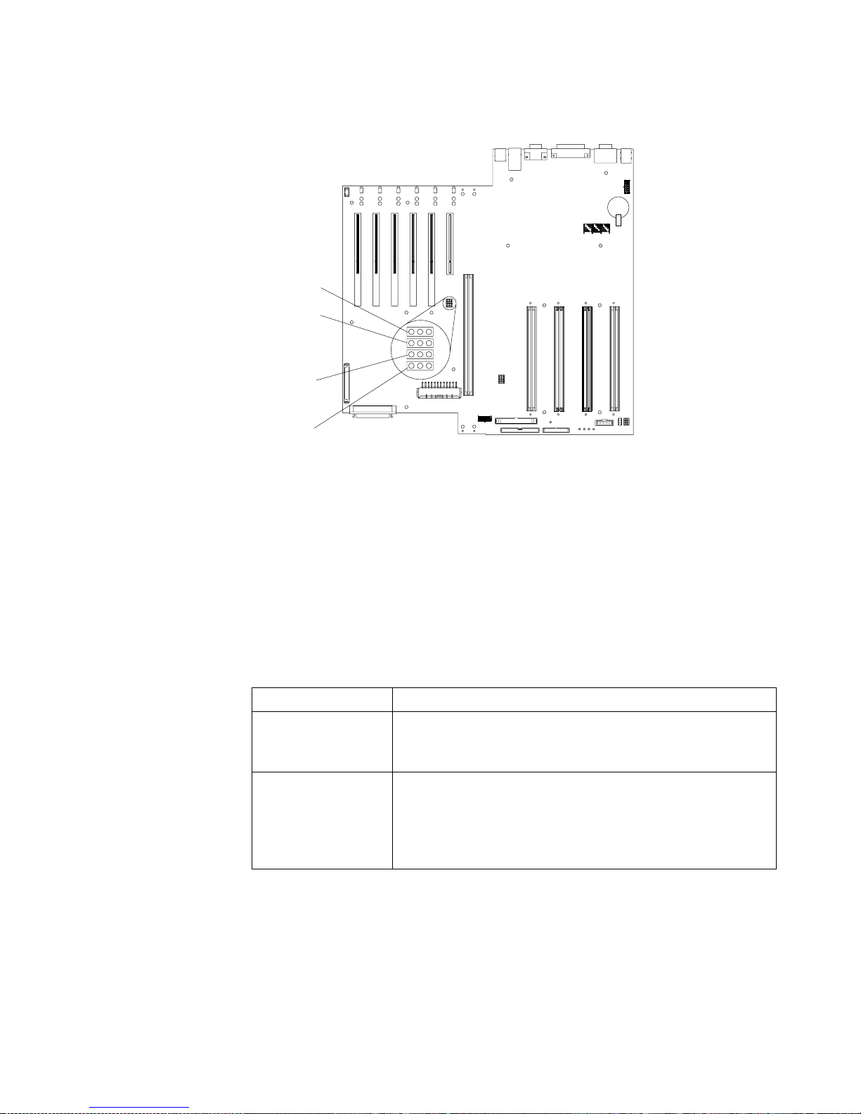
The following illustration shows the power-on password override jumper (J15) on
the system board.
Administrator password
Select this choice to set an administrator password. The administrator password
provides access to all choices on the Configuration/Setup Utility main menu. You can
set, change, or delete both the administrator and power-on passwords, and allow a
power-on password to be changed by the user.
Attention: If an administrator password is set and then forgotten, it cannot be
overridden or removed. You must replace the system board.
The following table provides a summary of the password features.
Table 2. Power-on and administrator password features.
Type of password Results
Power-on password • Type the password to complete the system startup.
• All choices are available on the Configuration/Setup Utility
main menu.
Administrator
password
• No password is required to start the system.
• Type the password to access the Configuration/Setup Utility
program.
• All choices are available on the Configuration/Setup Utility
main menu.
Flash ROM
page swap
jumper (J14)
Power-on
password
override
jumper (J15)
Reserved (J3)
Reserved (J17)
Page 32

20 IBM® xSeries 350: Use r’s Reference
Using the SCSISelect utility program
SCSISelect is a built-in, menu-driven configuration utility program that you can use
to:
• View the default SCSI IDs
• Locate and correct co nfiguration conflicts
• Perform a low-level format on a SCSI hard disk
The following sections provide the instructions needed to star t the SCSISelect Utility
and descriptions of the available menu choices.
Note: If your server has a RAID adapter installed, use the configuration method
supplied with the RAID adapter to view or change SCSI settings for attached
devices.
Starting the SCSISelect utility program
To start the SCSISelect utility program:
1. Turn on the se rver.
2. When the <<< Press <CTRL><A> for SCSISelect™ Utility! >>> prompt appears,
press Ctrl+A.
Note: If an administrator password has been set, a prompt appears asking you to
type the password to start the SCSISelect Utility program.
3. When prompted, select either channel A (internal) or channel B (external).
4. Use the arrow keys to select a choice from the menu.
• Press Esc to return to the previous menu.
• Press F5 to switch between color and monochrome modes (if your monitor
permits).
5. Follow the instructio ns on the screen to change the settings of the selected items;
then, press Enter.
Administrator and
power-on password
• You can type either password to complete the system startup.
• The administrator password provides access to all choices on
the Configuration/Setup Utility main menu. You can set,
change, or delete both the administrator and power-on
passwords, and allo w a power-on password to be changed by
the user.
• The power-on password provides access to a limited set of
choices on the Configuration/Setup Utility main menu. This
limited access might include changing or deleting the poweron password.
Table 2. Power-on and administrator password features.
Type of password Results
Page 33

Chapter 3. Configuring your serv er 21
Choices available from the SCSISelect menu
The following choices appear on the SC SISe lect Utility menu:
• Configure/View Host Adapter Settings
Select this choice to view or change the SCSI controller settings. To reset the SCSI
controller to its default values, press F6; then, follow the instructions that appear
on the screen.
You can view or change the following controller settings:
— Host Adapter SCSI ID
Select this choice to view the SCSI controller ID, normally 7.
— SCSI Parity Checking
Select this choice to view the assigned value of Enabled.
— Host Adapter SCSI Termination
Select this choice to view the assigned value of Enabled.
— Boot Device Option s
Select this choice to configure startable device parameters. Before you can
make updates, you must know the ID of the device whose parameters you
want to configure.
— SCSI Device Configuration
Select this choice to configure SCSI device parameters. Before you can make
updates, you must know the ID of the device whose parameters you want to
configure.
Note: The Maximum Sync T ransfer Rate repr esents the transfer rate for Ultra
SCSI devices.
– The transfer rate for Ultra160 SCSI LVD devices is 160.0
– The transfer rate for Ultra2 SCSI LVD devices is 80.0
– The transfer rate for Fast SCSI devices is 20.0
— Advanced Configuration Options
Select this choice to view or change the settings for advanced configuration
options.
• SCSI Disk Utilities
Select this choice to view the SCSI IDs that are assigned to each device or to
format a SCSI device.
To use the utility program, select a drive from the list. Read the screens carefully
before making a selection.
Note: If you press Ctrl+A before the selected drives are ready, an Unexpected
SCSI Command Failure screen might appear. Restart the server and watch
the SCSISelect messages as each drive spins up. After the drive that you
want to view or format spins up, press Ctrl+A.
Page 34

22 IBM® xSeries 350: Use r’s Reference
Page 35

© Copyright IBM Corp. 2001 23
Chapter 4. Using the ServerGuide CDs
The ServerGuide CDs include easy-to-use software setup and installation tools that
are specifically designed for your IBM server. The ServerGuide Setup and Installation
program detects the server model and hardware options that are installed and uses
that information during setup to configure the hardware. The ServerGuide tools
simplify NOS installations by providing updated device drivers, and in some cases,
installing them automatically.
If a newer version of the ServerGuide software is available, you can purchase an
update package. For details, see the ServerGuide Updates form that comes with your
server library, or go to the ServerGuide fulfillment Web site at
http://www.ibm.com/pc/coupon
The ServerGuide software has these features to make setup easier:
• An easy-to-use interface with online help
• Diskette-free setup and configuration programs that are based on detected
hardware
• Performance Optimizer program, which easily tunes your server for your
environment
• A system BIOS update prog ram, which updates the BIOS directly from the CD
• Device drivers that are provided for your server model and detected hardware
• NOS partition size and file-system type that are selectable during setup
• Powerful application programs and administration tools
Page 36

24 IBM® xSeries 350: Use r’s Reference
Features at a glance
The following is a summary of ServerGuid e fea tures.
Note: Exact features and functions can vary with different versions of the
ServerGuide software. To learn more about the version that you have, start the
Setup and Installation CD and view the online Overview.
Setup and Installation CD
Note: The ServerGuide progra m
requires a supported IBM
server with an enabled
startable (bootable) CD-ROM
drive. Not all features are
supported on all models.
• Sets system date and time.
• Detects the ServeRAID adapter or
controller and runs the
ServeRAID configuration
program.
• Updates the licensed internal
code (firmware) level without
creating diskettes.
• Checks the system BIOS level to
determine whether a later level is
available from the CD. You can
update BIOS witho u t creating
diskettes.
• Updates firmware for Advanced
System Management adapters
and controllers.
• Provides the Performance
Optimizer program to e asily tune
your server for your
environment.
• Creates a System Partition on the
default drive. You can run serverspecific utility programs after
setup.
• Detects installed hardwa r e
options and provides updated
device drivers for most adapters
and devices.
Setup and Installation CD
(continued)
• Creates a Setup Replication
Diskette for replicating setup
selections for other servers of the
same model.
• Provides diske tte-free ins tallation
for Windows 2000, Windows NT,
and NetWare operating systems.
• Provides a replicat ed inst a llat ion
path for multiple Windows 2000,
Windows NT Server 4.0, and
Wind ows Enterprise Edit ion, and
Red Hat Linux.
• Includes an online README file
with links to tips for your hardware and NOS installation.
Note: Installation requires your
NOS CD.
System Updates and Applicatio ns CD
• Creates diagnostic, RAID, device
driver, and other support
diskettes from th e CD; or wit h an
Internet connection, you can
check for an update fr om a
dedicated IBM file transfer
protocol (FTP) server.
• Installs some updates without
requiring diskettes. Where
applicable, you can run
executable files directly fr om the
CD or unzip files to any drive on
your server or another server on
your network.
• Includes a large library of fully
tested dev ice drivers for your
server.
• Includes a search function to help
you locate updates by title or
keywords.
• Installs powerful applications
directly from the CD. See the CD
label for a current list of
applications.
Page 37

Chapter 4. Using the ServerGuide CDs 25
Setup and configuration overview
When you use the Setup and Installation CD, you do not need setup diskettes. You can
use the CD to configure any supported IBM server model. The setup program checks
your system BIOS, service processors, and other system hardware to determine if
system updates are available. The setup program provides a list of tasks that are
required to set up your server model. On RAID servers, you can run the ServeRAID
Manager program to create logical drives.
Note: Exact features and functions can vary with different versions of the
ServerGuide software.
When you start the Setup and Installation CD, the following happens:
• You are prompted for your language, country, and keyboard layout. (This
information is stored and later passed on to the N OS installation program.)
• ServerGuide displays choices for running the configuration programs. For
example:
— The Express Configuration method runs the required programs for your
server, based on the hardware that is detected.
— The Custom Configuration method displays all programs that are available
for your server, and yo u deci de which programs to run.
— The Replicated Configuration method provides the option of duplicating
your setup selections to other servers that are the same model.
• If you select the Custom Configuration method, the following programs are
optional. If you select the Express Configuration method, some or all of these
programs are run, depending on the hardware that is detected.
— The Set Date and Time feature is provided so that you do not have to use the
Configuration/Setup Utility program to access th ese settings.
— ServerGuide checks the server BIOS and microcode (firmware) levels for
supported options and then checks the CD for a newer level. CD content can
be newer than the hardware. ServerGuide can perform a flash update of the
BIOS.
— The ServeRAID configuration program starts, leading you through the entire
configuration process.
— The Performance Optimizer program easily tunes your server for your
environment.
— ServerGuide creates a System Partition on the default drive.
• ServerGuide displays a confirmation summary, so tha t you will know when you
have completed all the required tasks. Then, you are ready to install your NOS.
Notes:
1. Plug and Play adapters are configur ed automati cally. Non-Plug and Play ada pters
or non-IBM adapters might r equir e sw itch settings, additiona l device drivers, and
installation after the NOS is installed. See the documentation that comes with the
adapter.
2. Diagnostics for your server come in your system BIOS or on a separate
diagnostics CD.
Page 38

26 IBM® xSeries 350: Use r’s Reference
System Partition
ServerGuide creates a 50 MB System Partition on the default drive. The System
Partition contains server-specific utility programs such as service processor disk
operating system (DOS ) utilities, system diagnostics, flash BIOS updates, and other
programs.
Note: Programs in the System Partition vary by server model, and not all server
models run utility programs from the System Partition. To determine which
ones do, start the Setup and Installation CD and view the online Overview.
After setup is complete, you can access programs in the System Partition by restarting
the server and pressing Alt+F1 when the prompt is displayed. The System Partition
menu displays the programs that are available on your server model.
Installing a NOS
You can use ServerGuide to shorten your installation time. ServerGuide provides the
necessary device drivers, based on the hardware that you have and the NOS that you
are installing. The following is a brief explana tion of a typical ServerGuide NOS
installation.
Note: Exact features and functions can vary with different versions of the
ServerGuide software
• After you have completed the setup process, the operating system installation
program starts. (You will need your copy of the NOS CD to complete the
installation.)
• ServerGuide stores information about the server model, service processor, hard
disk controllers, and network adapters. It then checks the CD for newer device
drivers. This information is stored and then passed to th e N OS installation
program.
• With some NOS installations, you can create a NOS Replication Diskette for setting
up additional servers. The diskette will contain the Internet protocol (IP) address,
server name, and other selections.
• ServerGuide pr esents NOS partition options that are based on your NOS selection
and the installed hard disk drives.
• If you are installing the NOS from diskette, ServerGuide displays the required
diskettes that you must create, and the optional diskettes that you might want to
create. The diskettes that you can create are the device-driver diskettes for the
installed adapters or controllers.
ServerGuide prompts you to insert your NOS CD and restart the server . At this point,
the installation program for the NOS (for example, Microsoft Windows 2000) takes
control to complete the installation.
Setting up or updating multiple servers
You can use ServerGuide to create diskettes that help you set up or update multiple
servers. You can modify information on the diskettes as you use them to set up or
update other servers.
Note: Availability and function can vary by server model and by the hardware that is
installed.
You can create a Setup Replication Diskette, which contains your hardware
configuration selections. Use this diskette to replicate selections to other servers that
are of the same model.
Page 39

Chapter 4. Using the ServerGuide CDs 27
You can create a NOS Replication Diskette, which contains your server name, domain
name, and other information that yo u need to complete multiple installations. This
feature supports systems running Windows 2000, Windows NT Server 4.0, and Re d
Hat Linux.
Installing your NOS without ServerGuide
If you have already configured the server hardware and you decide not to use
ServerGuide to install your NOS, download the latest NOS installation instructions:
1. Go to http://www.ibm.com/pc/support
2. Click Servers.
3. From the Family field, select your server model.
4. Click OS Installation. The available installation instructions are listed.
Additional programs included with ServerGuide
As a convenience, ServerGuide comes with additional software to assist you with the
server installation.
A variety of powerful applications are included with ServerGuide. Offerings can vary
with the different versions of the ServerGuide software. Check the appl ication CD
labels for a list of applications, or start the Setup and Installation CD and view the
online Overview .
Error symptoms
This section provides ServerGuide error symptoms and probable solutions.
Symptom Action
Setup and Installation CD will not
start.
• Ensure that the system is a supported server model with a startable (bootable)
CD-ROM drive.
• If the startup (boot) sequence settings have been altered, be sure that the CDROM drive is first in the startup sequence.
• If more than one CD-ROM drive is installed, be sure that only one drive is set
as the primary drive. Start the CD from the primary drive.
ServeRAID program cannot
view all installed drives or
cannot install the NOS.
• Ensure that there a re no duplicate SCSI IDs or IRQ assignments.
• Ensure that the hard disk drive is connected properly.
The operating system
installation program
continuously loops.
Free up more space on the hard disk.
ServerGuide will not start your
NOS CD.
Ensure that the NOS CD is supported by ServerGuide. See the Setup and Installation
CD label for a list of support ed NOS versions.
Cannot install the NOS. Ensure that the NOS is supported on your server. If the NOS is supported, either
there is no logical drive defined (ServeRAID systems) or the ServerGuide System
Partition is not present. Run the ServerGuide setup and config urat ion program and
ensure that the setup is comple te.
Get "time out" or "Unknown
host" errors on the System
Updates and Appl ica tio ns CD .
Ensure that you have access to the Internet through FTP directly.
Page 40

28 IBM® xSeries 350: Use r’s Reference
Page 41

© Copyright IBM Corp. 2001 29
Chapter 5. Installing options
This chapter provides instructions to help you add options to your server.
Major components view of the xSeries 350 server
The orange color on components and labels in your server identifies hot-swap or hotplug components. You can install or remove these components while the system is
running, provided that your system is configured to support this function. For
complete information about installing or removing a hot-swap or hot-plug
component, see the detailed information in this chapter.
The blue color on components and labels indicates touch points where a component
can be gripped, a latch moved, and so on.
The following illustration shows the major components of the xSeries 350 server.
Page 42

30 IBM® xSeries 350: Use r’s Reference
Terminator card
Microprocessor
Hot-swap drive
tray assembly
Filler panel
for hot-swap
drive tray
Filler panel
for power
supply bay
Power supply
Hot-swap fans
Hot-swap fans
Memory board
Dual in-line
memory module
(DIMM)
Advanced System
Management
Interconnect board
System board
Diagnostics panel
C
P
U
M
e
m
o
r
y
Fa
n
A
B
C
1
2
3
DA
S
D
N
M
I
S
P
B
u
s
E
v
e
n
t
L
o
g
N
o
n
R
e
d
O
v
e
r
S
p
e
c
Te
m
p
P
C
I
B
u
s
Powe
r
S
u
p
p
l
y
Page 43
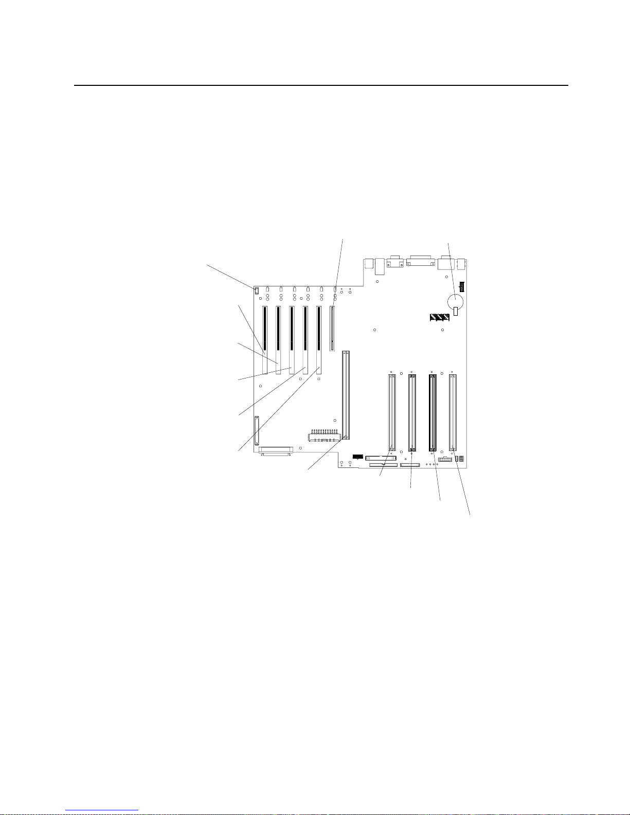
Chapter 5. Installing options 31
Component locations
This section provides illustrations of the system board, diagnostic LED panel,
memory board, and Advanced System Management processor c omponent locations.
System board component locations
The following illustration shows the location of the system-board connectors for userinstallable options.
PCI slot 1
32-bit
33 MHz (J50)
PCI slot 2
64-bit
66 MHz (J51)
PCI slot 3
64-bit
66 MHz (J52)
PCI slot 4
64-bit
66 MHz (J53)
PCI slot 5
64-bit
33 MHz (J54)
PCI slot 6
64-bit
33 MHz (J55)
Microprocessor slot 1 (J34)
Microprocessor slot 2 (J35)
Microprocessor slot 3 (J36)
Microprocessor slot 4 (J37)
Memory board (J40)
Battery
PCI hot-plug
switch card
(J1)
Page 44

32 IBM® xSeries 350: Use r’s Reference
The following illustration shows the location of the cable connectors on the system
board.
Power signal
(J16)
Diagnostic panel
(J18)
IDE (J21)
120 MM fan
(J30)
120 MM fan
(J49)
Main power
(J71)
Internal SCSI
(J38)
External SCSI
(J39)
Advanced System
Management
(J69, J68, J67)
processor
Page 45

Chapter 5. Installing options 33
The following illustration shows the location of the input/output external port
connectors on the system board.
The following illustration shows the location of the flash ROM page swap jum p er
(J14) and power-on password override jumper (J15) on the system board. Jumper J14
is located at the top of the jumper block, and jumper J15 is located immediately below
jumper J14.
Keyboard (bottom)
Mouse (top)
(J64)
Serial A
(bottom)
Serial B
(top)
(J60)
Parallel (J63)
Video (J62)
Ethernet (J79)
USB 1
USB 2
(J61)
Flash ROM
page swap
jumper (J14)
Power-on
password
override
jumper (J15)
Reserved (J3)
Reserved (J17)
Page 46

34 IBM® xSeries 350: Use r’s Reference
Notes:
1. Turn off the server; then, disconnect all power cords and external cables before
moving any jumpers.
Attention: Jumpers J17 and J3 are located on the same jumper block as jumpers
J14 and J15. These jumpers are set to Disabled. Do not change the settings on
these jumpers. If you change the settings on these jumpers, the server will fail.
2. See “Changing jumper positions” on page 58 for addi tional in formatio n on setti ng
jumpers.
Table 3. Jumpers J14 and J15 on the system board.
Jumper name Description
Flash ROM page swap (J14) The default position is a jump er installed on pins 2 and 3.
See “Recovering BIOS” on page 104 for additional information.
Power-on password override
(J15)
Changing the position of this jumper bypasses the power-on
password check if the jumper has been moved since the server was
last powered on. You do not need to move the jumper back to the
default position after the password is overridd en. The default is a
jumper on pins 1 and 2.
Changing the position of this jumper does not affect the
administrator password check if an administrator password is set.
See “Power-on password” on page 18 for ad ditional information on
the power-on password.
Page 47

Chapter 5. Installing options 35
The following illustration shows the location of the microprocessor speed (corefrequency selection) jumper block on the system board. The jumpers on this block are
in the following order, from top to bottom: J13, J27, J28, and J29. See “Installing a
microprocessor” on page 55 for th e jumper speed settings.
Note: Any system-board jumper blocks that are not shown in the illustrations in this
book are reserved.
Microprocessor
speed jumpers
J13
J27
J28
J29
123
Page 48
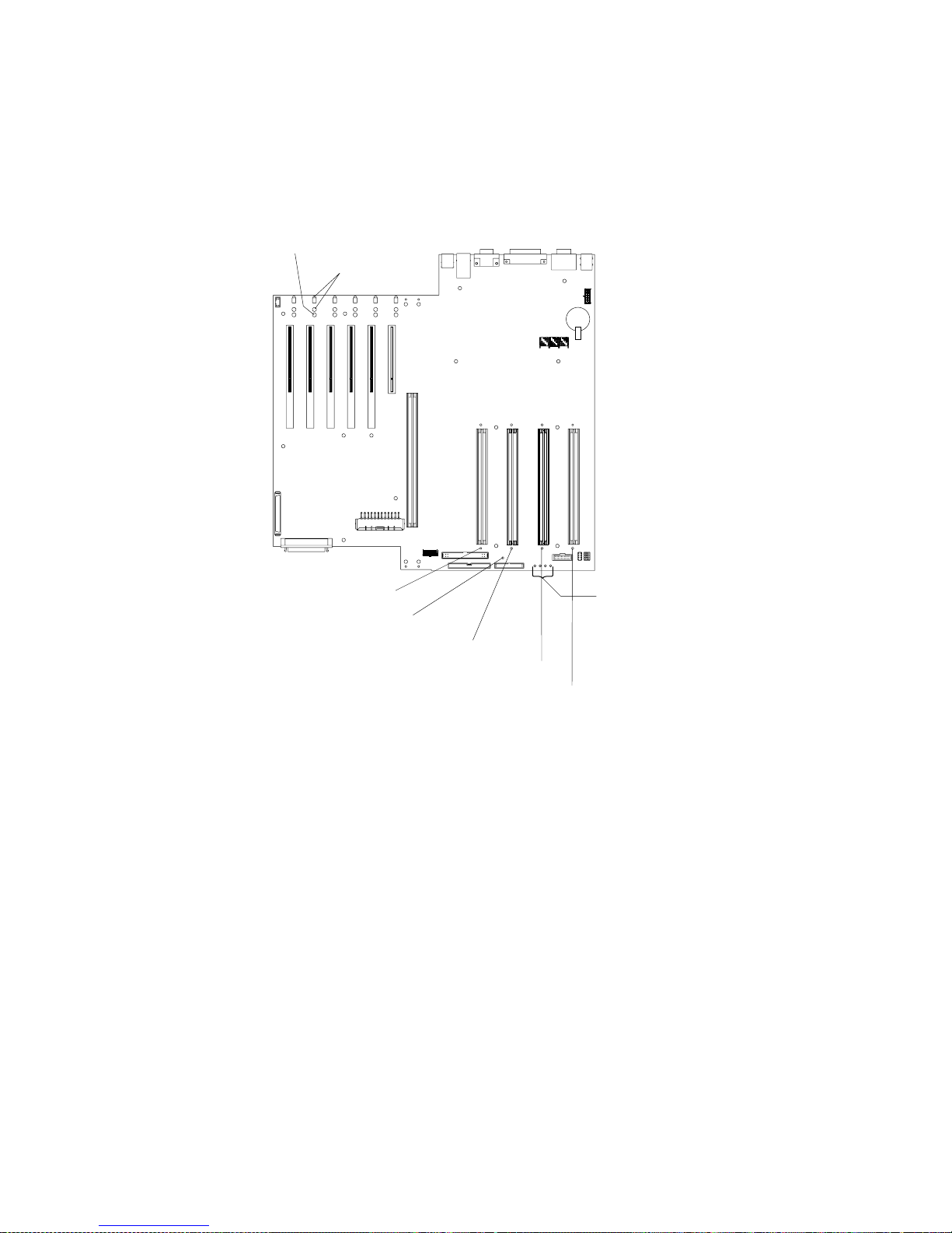
36 IBM® xSeries 350: Use r’s Reference
System board LED locations and diagnostic LED panel
The following illustration shows the location of the lights on the system board. You
might need to refer to this illustration when solving problems with the server.
Microprocessor 1 error
light
Microprocessor 2 error
light
Microprocessor 3 error
light
Microprocessor 4 error
light
PCI slot
attention lights
PCI slot
power-on light
Microprocessor or
terminator card
present lights
Post OK light
Page 49

Chapter 5. Installing options 37
The following illustration shows the location of the LEDs on the diagnostic panel.
The diagnostic panel LEDs are visible through a special cutout area located to the left
of the cover-release latch on the top cover. However, to determine the exact location
of the error condition in your server, you might need to remove the top cover to view
the location of the error LED on the diagnostic panel.
Note: The diagnostic panel is also called the LED card.
The meanings of these LEDs are as follows:
NMI Nonmaskable interrupt
SP Bus Service processor failure
PCI Bus A (PCIA) PCI bus A fault
PCI Bus B (PCIB) PCI bus B fault
PCI Bus C (PCIC) PCI bus C fault
DASD Hard disk drive fault
Memory Memory fault
CPU Microprocessor fault
FAN Fan failure
TEMP System temperature failure
NON RED Nonredundant power mode
OVER SPEC Over specification
Power supply 1 Power supply number 1 failure
Power supply 2 Power supply number 2 failure
Power supply 3 Power supply number 3 failure
System board connector
Diskette drive connector
CPU
Memory
Fan
A B C
1 2 3
DASD
NMI
SP Bus
Event Log
Non Red
Over Spec
Temp
PCI
Bus
Power
Supply
Page 50
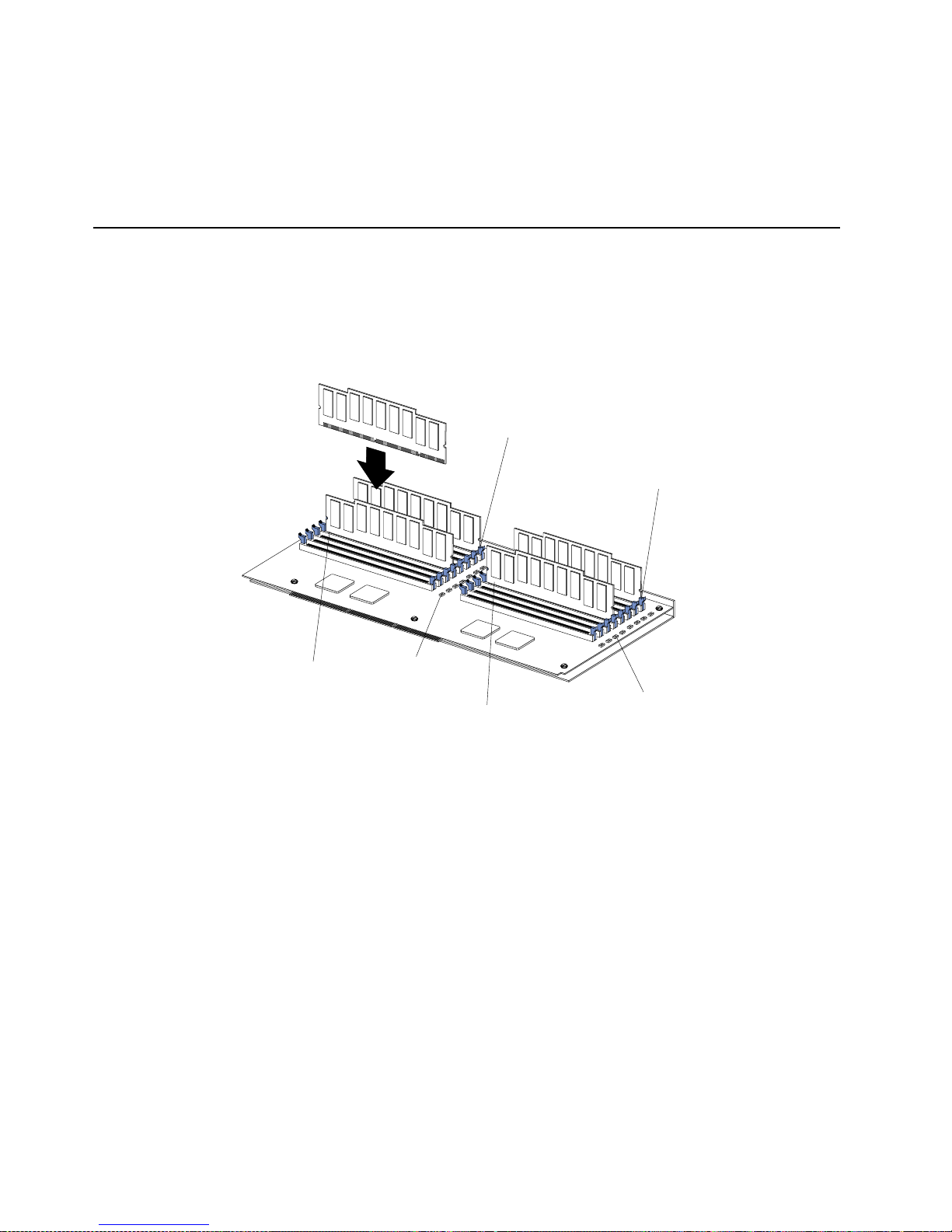
38 IBM® xSeries 350: Use r’s Reference
Notes:
1. The server does not support replaceable voltage regulator modules (VRMs).
2. The server supports a maximum of three PCI buses.
3. The server supports a maximum of three power supplies.
4. See “Light Path Diagnostics” on page 109 for a detailed description of these LEDs.
Memory board component locations
The following illustration shows the location of the dual in-line memory module
(DIMM) connectors and error LEDs on the memory board.
Note: Some of the DIMM error LEDs are not visible in this illustration. The memory
board contains 16 error LEDs, one error LED for each DIMM connector.
Memory slot 1
Memory slot 5
Memory slot 9
Memory slot 13
Error LEDs
Error LEDs
Page 51

Chapter 5. Installing options 39
Advanced System Management processor component locations
The following illustration sho ws the connectors and lights for the Advanced System
Management pr o cess o r.
Note: The Advanced System Management processor is also called the service
processor card.
Before you begin
Before you begin to install options in your se rver, read the following information:
• Become familiar with the safety and handling guidelines specified under
“Handling static sensitive devices” on page 40, and read the safety statements in
“Safety” on page v. These guidelines will help you work safely with your server
or options.
• You do not need to turn off the server to install or replace hot-swap power
supplies, hot-swap drives, hot-swap fans, Active PCI (hot- plug) adapters, or hotplug USB devices.
• The orange color on components and labels in your server identifies hot-swap or
hot-plug components. You can install or remove these components while the
system is running, provided that your system is configured to support this
function.
• The blue color on components and labels identifies touch points where you can
grip a component, move a latch, and so on .
• Make sure th at you have an adequate number of properly grounded electrical
outlets for your server, monitor, and any other options that yo u intend to install.
• Back up all important data before you make changes to disk drives.
• For a list of supported options for the xSeries 350 server, refer to
http://www.ibm.com/pc/us/compat on the World Wide Web.
Serial port Advanced System Management
processor connectors
System board connectorService processor
error
Power LED
Page 52

40 IBM® xSeries 350: Use r’s Reference
System reliability considerations
To help ensure proper cooling and system reliability, make sure that:
• Each of the drive bays has either a drive or a filler panel installed.
• Each of the power-supply bays has either a power supply or a filler panel
installed.
• Th er e is at least 50 mm (2 inches) of ventila ted s p ace a t the s ides o f t he server an d
100 mm (4 inches) at the rear of the server.
• The top cover is in place during normal operation.
• The top cover is removed for no longer than 30 minutes while the server is
operating.
• A r emoved hot-swap drive is replaced within two minutes of removal.
• Cables for optional adapters are routed according to the instructions that are
provided with the adapters.
• A failed fan is replaced within 48 hours.
Working inside the server with the power on
Your server supports hot-plug, hot-add, and hot-swap devices and is designed to
operate safely while turned on with the cover removed. Follow these guidelines when
you work inside a server that is turned on:
• Avoid loose-fitting clothing on your forearms. Button long-sleeved shirts before
working inside the server; do not wear cuff links while you are working inside the
server.
• Do not allow your necktie or scarf to hang inside the server.
• Remove jewelry, such as bracelets, necklaces, rings, and loose-fitting wrist
watches.
• Remove items from your shirt pocket (such as pens or pencils) that could fall into
the server as you lean over it.
• Take care to avoid dropping any metallic objects, such as paper clips, hair pins, or
screws, into the server.
Handling static sensitive devices
Attention: Static electricity can damage electronic devices and your system. To
avoid damage, keep static-sensitive devices in their static-protective bags until you
are ready to install them.
To reduce the possibility of electrostatic discharge, observe the following precautions:
• Limit your movement. Movement can cause static electricity to build up around
you.
• Handle the device carefully, holding it by its edges or its frame.
• Do not touch solder joints, pins, or exposed printed circuitry.
• Do not leave the device where others can handle and possibly damage the device.
• While the device is still in its anti-static bag, touch it to an unpainted metal part of
the system unit for at least two seconds. (This drains static electricity from the
package and from your body.)
• Remove the device from its package and install it directly into your system unit
without setting it down. If it is necessary to set the device down, place it on its
Page 53

Chapter 5. Installing options 41
static-protective bag. (If your device is an adapter, place it component side up.)
Do not place the device on your system unit cover or on a metal table.
• Take additional care when handling devices during cold weather because heating
reduces indoor humidity and increases static electricity.
Removing the server top cover and bezel
Review the information in “Before you begin” on page 39.
To remove the server top cover and bezel:
1. Lift the plastic cover-release latch near the edge of the top cover.
2. Slide the top cover slightly toward the rear of the server; the cover will stop after
moving approximately 25 mm (1 inch). Lift the cover off the server, and set the
cover aside.
Attention: For proper cooling and airflow, replace the top cover before turning
on the server . Operating the server for extended periods of time (over 30 minutes)
with the top cover removed might damage server components.
3. Release the two tabs at the top edge of the bezel, and pu ll the top of the bezel
slightly away from the server.
4. Pull the bezel up to release the two tabs at the bottom edge of the bezel. Store the
bezel in a safe plac e.
Top cover
Release latch
Release latch
Cover release latch
Bezel
Page 54

42 IBM® xSeries 350: Use r’s Reference
Working with adapters
The following illustration shows the location of the Active™ PCI adapter expansion
slots on the system board.
Note: Active PCI slots are also called hot-plug PCI slots.
The PCI bus configuration follows:
• Hot-plug, 32-bit PCI slot 1 (on PCI bus A, 33 MHz)
• Hot-plug, 64-bit PCI slots 2 through 4 (on PCI bus B, 66 MHz)
• Hot-plug, 64-bit PCI slots 5 through 6 (on PCI bus C, 33 MHz)
• Power-on lights for Active PCI slots
• Internal attention lights for Active PCI slots
• External attention lights for Active PCI slots
This section gives the procedure for installing a hot-plug PCI adapter. If your
operating system supports hot-plug PCI adapters, you can replace a failing hot-plug
PCI adapter with a new adapter of the same type without turning off power to the
server. If your operating system and adapter also support the hot-add feature, you
can install a new adapter without turning off the power to the server.
Before you begin:
• Review the information in “Before you begin” on page 39 and “Working inside
the server with the power on” on page 40.
• Read the documentation that comes with your adapter for any special
requirements or restrictions.
• Read the documentation that comes with your operating system.
Attention: Do not remove a hot-plug PCI adapter before performing the operatingsystem-defined procedure for disabling the Active PCI (hot-plug) slot that contains
the adapter. Doing so migh t caus e your system to lo ck up. Refer to your operatingsystem documentation.
PCI slot 1
32-bit
33 MHz (J50)
PCI slot 2
64-bit
66 MHz (J51)
PCI slot 3
64-bit
66 MHz (J52)
PCI slot 4
64-bit
66 MHz (J53)
PCI slot 5
64-bit
33 MHz (J54)
PCI slot 6
64-bit
33 MHz (J55)
PCI hot-plug
switch card
(J1)
PCI slot
attention lights
PCI slot
power-on light
Page 55

Chapter 5. Installing options 43
Installing a hot-plug adapter
To install a hot-plug PCI adapter :
Attention: When you handle static-sensitive devices, take precautions to avoid
damage from static electricity. For details on handling these devices, see “Handling
static sensitive devices” on page 40.
1. Remove the top cover (see “Removing the server top cover and bezel” on page
41).
2. Determine which expansion slot you will use for the adapter.
Note: All six PCI slots support hot-plug PCI adapters.
3. Disable the selected PCI slot from your operating system. (See the documentation
that comes with your operating system for information about disabling a hot-plug
PCI slot.) Disabling the PCI slot turns off the power-on light for that PCI slot.
Attention: Make sure that the power-on light for the hot-plug PCI slot is off
before you continue with the next step.
4. Remove the expansion-slot cover:
a. Rotate the adapter-retention latch counterclockwise.
b. Lift the tab on the top of the expansion-slot cover; then, remove the
expansion-slot cover from the server. Store it in a safe place for future use.
c. Press on the rear of the adapter-retention assembly, and lift the adapter-
rete ntion cover.
Attention: Expansion-slot covers must be installed on all empty slots. This
maintains the electronic emissions characteristics of the system and ensures
proper coo li ng of system components.
5. See the documentation that comes with your adapter for any cabling instructions.
It might be easier for you to route any cables before you install the adapter.
6. Remove the adapter from the static-protective bag.
Attention: Avoid touching the components and gold-edge connectors on the
adapter.
7. Place the adapter, component-side up, on a flat, static-protective surface.
Page 56

44 IBM® xSeries 350: Use r’s Reference
8. Ins tall the adapter:
a. Carefully grasp the adapter by its top edge or upper corners, and align it with
the expansion slot on the system board.
b. Press the a dapter firmly into the expansion slot.
Attention: When you install an adapter in the server, be sure that it is
completely and correctly seated in the system-board connector. Incomplete
insertion might cause damage to the system board or the adapter.
c. Lower the tab over the top corner of the adapter. Rotate the adapter-retention
latch clockwise until it snaps into pla c e.
9. Connect any needed cables to the adapter.
10. Enable the PCI slot from your operating system. (Refer to the documentation that
comes with your operating system for information about enabling a hot-plug PCI
slot.) Make sure that the power-on light for the hot-plug PCI slot comes on.
11. If you have other options to install or remove, do so now; otherwise, go to
“Installing the server top cover and bezel” on page 62.
Cabling the ServeRAID adapter
You can install a n optional IBM ServeRAID adapter in your server to control the
internal hot-swap hard disk drives (that is, so that yo u can conf igure the internal hotswap hard disk drives into disk arrays). To do this, you must turn off the server,
disconnect the internal SCSI cable from the integrated SCSI controller on the system
board, and connect the cable to a ServeRAID adapter. Refer to your ServeRAID
adapter option documentation for complete instructions on installing a ServeRAID
adapter in your server. Refer to the Using IBM ServeRAID book on the Documentation
CD for information on ServeRAID adapters and controllers.
Expansion-slot cover
Pow er-on light
Adapter
Adapter
retention
cover
Adapter
retention
latch
Tab
Plastic
dividers
Page 57

Chapter 5. Installing options 45
The following procedure describes the cable routing that is necessary when you install
a ServeRAID adapter. You can also cable a ServeRAID adapter to external hard disk
drives.
Notes:
1. See the documentation that comes with your adapter for any cabling instructions.
2. Cable identifiers are printed on the cables that come with your server and
options. Use these identifiers to connect the cables to the correct connectors. For
example, the hard disk drive cables are labeled HDD.
To cable the ServeRAID adapter:
1. Turn off the server.
2. Remove all adapters from the Active PCI adapter slots.
3. Remove the plastic dividers between the PCI adapter slots.
4. Slide the fan assembly toward the front of the server and lift to remove it.
5. Disconnect the internal SCSI cable from the SCSI connector (J38) on the system
board. See page 32 for the location of the SCSI connector on the system board.
6. Carefully thread the disconnected end of the internal SCSI cable out of the chassis,
pulling the cable out of the opening in the chassis.
7. Rei nstall the fan assembly in the server.
8. Replace the plastic dividers between the PCI adapter slots.
9. Rei n stall the adapters in the PCI adapter slots.
10. Install the ServeRAID adapter in the selected PCI slot. See “Installing a hot-plug
adapter” on page 43 for adapter installation instructions. See your ServeRAID
adapter option documenta tion for additional information on installing a
ServeRAID adapter in your server and connecting the SCSI cable to a ServeRAID
adapter.
ServeRAID adapter
Plastic
dividers
Fan assembly
release latch
SCSI connector
(J38)
Page 58
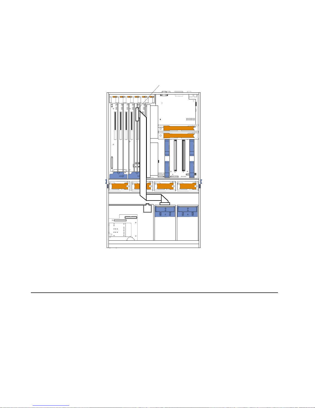
46 IBM® xSeries 350: Use r’s Reference
11. Route the SCSI cable to the ServeRAID adapter using the following illustration as
a guide.
Attention: When you route the SCSI cable, observe the following:
• Do not block the ventilated space in front of the fan assembly.
• Do not place the SCSI cable fold on top of the fan assembly.
• Do not route the SCSI cable over the memory board assembly.
12. Connect the SCSI cable to an internal channel connector on the ServeRAID
adapter.
Note: See to the Using IBM ServeRAID book on the Documentation CD for
information on ServeRAID adapters and controllers.
Installing internal drives
If you add different types of drives, your system can read multiple types of media and
store more data. Several types of drives are available, such as:
• Diskette
• Hard disk
• CD-ROM
• DVD-ROM
• Tape
Note: The server supports external tape drives; however, the server does not support
internal tape drives.
ServeRAID adapter
CPU
Memory
Fan
A B C
1 2 3
DASD
NMI
SP Bus
Event Log
Non Red
Over Spec
Temp
PCI
Bus
Power
Supply
Page 59

Chapter 5. Installing options 47
Your server contains hardware that enables you to replace a failed hard disk drive
without turning off the server. Therefore, you have the advantage of continuing to
operate your system while a hard disk drive is removed or installed. These drives are
known as hot-swap drives.
Each hot-swap drive has two indicato r lights (see “Controls and Indicators” on page
6). If the amber hard disk drive status light for a drive is lit con tinuously, that
individual drive is faulty and requires replacement. When the hard disk drive status
light indicates a drive fault, you can replace a hot-swap drive without turning off the
server.
Each hot-swap drive that you plan to install must be mounted in a hot-swa p - d rive
tray. The drive must have a single connector attachment (SCA) connector. Hot-swapdrive trays come with hot-swap drives.
Internal drive bays
Interna l d riv es are installed in bays.
• Your server comes with one integrated drive electronics (IDE) CD-ROM drive and
one 3.5-inch, 1.44 MB diskette drive.
• The CD-ROM drive bay (bottom left front) supports 5.25-inch, half-high,
removable-media drives. A CD-ROM drive comes preinstalled in the server.
• You cannot install hot-swap drives in the left-front bays. You can install hotswap hard disk drives only in the hot-swap har d disk drive bays on the right front
side of the server.
• Your server supports a maximum of three stan dard and three optional 26 mm (1inch) slim-high, 3.5-inch, hot-swap hard disk drives in the hot-swap bays. The
standard hot-swap bays are bays 1 through 3 (from bottom to top). The optional
hot-swap bays are bays 4 through 6 (from bottom to top). Bays 1 through 3 are
located in the standard hard disk drive cage, to the left of bays 4 through 6 in the
optional hard disk driv e cage.
Note: The server does not support half-high hot-swap drives or internal tape
drives.
• The hot-swap bays are connected to a hot-swap drive backplane. The backplane is
a printed circuit board behind the bays.
CD-ROM drive
Diskette drive
Standard hard
disk d
riv
es
Optional hard
disk d
riv
es
Hot-swap bays (up to six)
Page 60

48 IBM® xSeries 350: Use r’s Reference
Installing a hot-swap hard disk drive
Note: You do not have to turn off the server to install hot-swap hard disk drives in
these bays.
To install a drive in a hot-swap bay:
Attention: When you handle static-sensitive device s, take precautions to avoid
damage from static electricity. For details on ha nd ling these devices, see “Handling
static sensitive devices” on page 40.
1. Review “Before you begin” on page 39.
2. Remove the filler panel from one of the empty hot-swap bays by inserting your
finger into the depression at the left side of the filler panel and pulling the pa nel
away from the server.
Attention: To maintain proper system cooling, do not operate the server fo r mor e
than 10 minutes without either a drive or a filler pane l installed in each bay.
3. Install the hard disk drive in the hot-swap bay:
a. Ensure that the tray handle is open (that is, perpendicular to the drive).
b. Align the drive assembly with the guide rails in the bay.
c. Gently push the drive assembly into the bay until th e drive stops.
d. Push the tray handle to the closed (locked) position.
e. Check the hard disk drive status indicator to verify that the hard disk drive is
operating properly.
Note: The hard disk drive activity light and hard dis k drive status ligh t on
the backplane match the hard-disk drive activity light a nd hard-disk
drive status light on the front of the server (see “Turning on the
server” on page 7).
If the amber hard disk status light for a drive is lit continuously, that
individual drive is faulty and needs to be replaced. If the green hard disk
activity light is flashing, the drive is being accessed.
Note: If your server has a ServeRAID controller or adapter installed, you might
need to reconfigure your disk arrays after installing hard disk drives. See
the Using IBM ServeRAID book on the xSeries Documentation CD for
information.
Filler panel
Drive tray
assembly
Drive tray handle
(in open position)
Page 61

Chapter 5. Installing options 49
Installing a 3-Pack Ultra160 Hot-Swap Expansion Kit
You can install an optional 3-Pack Ultra160 Hot-Swap Expansion Kit in your server to
connect three additional hot-swap hard disk drives in your server. This kit contains a
hot-swap hard disk drive backplane that you install adjacent to the standard hot-swap
hard disk drive backplane. Your server supports a maximum of two hot-swap drive
backplanes.
Notes:
1. In addition to the optional hot-swap drive backplane, the 3-Pack Ultra160 HotSwap Expansion Kit comes with a hard d isk drive cage. Do not install the hard
disk drive cage in your server. The hard disk drive cage is not compatible with
the xSeries 350 server.
2. Cable identifiers are printed on the cables that come with your server and
options. Use these identifiers to connect the cables to the correct connectors. For
example, the hard disk drive cables are labeled HDD.
3. For information on cabling options and using the 3-Pack Ultra160 Hot-Swap
Expansion option, see the documentation that com e s with the option kit.
4. For additional information on cabling, see “Cabling the ServeRAID adapter” on
page 44 and “Cabling the server” on page 76.
The following illustration shows the hot-swap-drive backplane component locations,
as viewed from the front of the server.
Note: The hard disk drive activity light and hard dis k drive status ligh t on the
backplane match the hard-disk drive activity light and hard disk drive status
light on the front of the server (see “Turning on the server” on page 7).
The following illustration shows the rear connectors on the hot-swap-drive
backplane, as viewed from the rear of the server.
Hard disk
drive activity
light (green)
Hard disk
drive status
light (amber)
SCSI hot-swap
hard disk drive
connector
Page 62
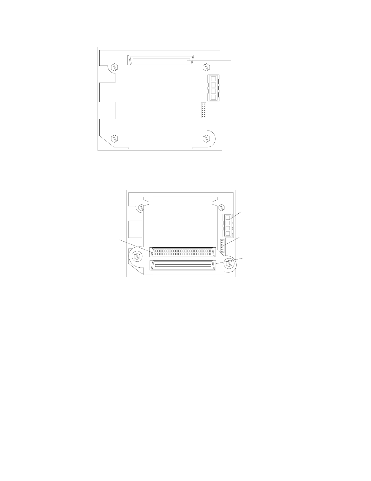
50 IBM® xSeries 350: Use r’s Reference
The following illustration shows the rear connectors on the SCSI repeater card, as
viewed from the rear of the server.
To install a 3-Pack Ultra160 Hot-Swap Expansion Kit:
Attention: When you handle static-sensitive device s, take precautions to avoid
damage from static electricity. For details on ha nd ling these devices, see “Handling
static sensitive devices” on page 40.
1. Review the information in “Before you begin” on page 39 and in “Safety ” on page
v.
2. Turn off the server and peripheral devices and disconnect all power cords and
external cables; then, remove the top cover (see “Removing the server top cover
and bezel” on page 41).
3. See the documentatio n that comes with the option to assemble the hot-swap
expansion option.
4. Align the hot- swap expansion option with the empty slot at the rear of the
optional hard disk drive cage, adjacent to the standard hot-swap hard disk drive
backplane.
SCSI cable
connector
SCSI power
cable connector
I C cable
connector
2
SCSI power
cable
connector
SCSI cable
connector
SCSI repeater
card cable
connector
IC cable
connector
2
Page 63
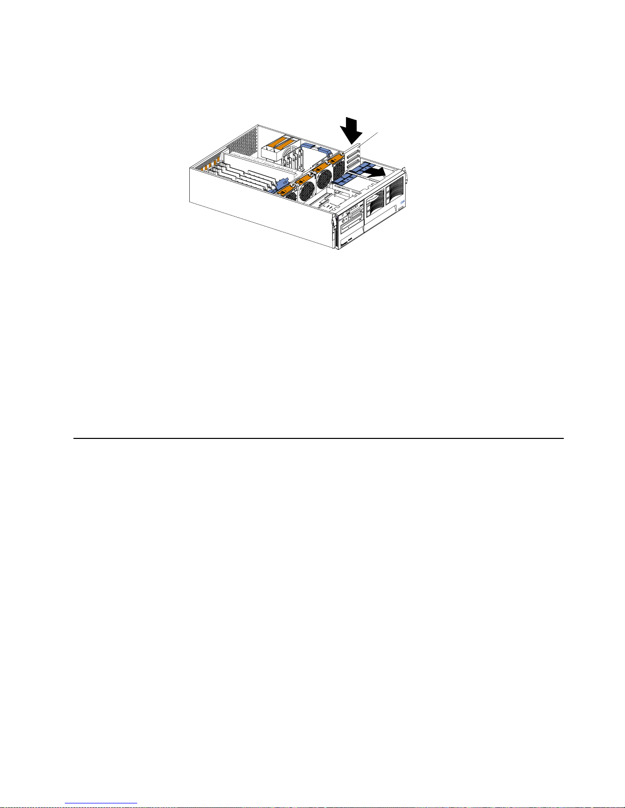
Chapter 5. Installing options 51
5. Slide the hot-swap expansion option down into the guides on the slot at the rear
of the optional hard disk drive cage, and secure it to the server with the blue slide
latch located on top of the optional hard disk drive cage.
6. See the documentatio n that comes with the option to complete the installation of
the option.
7. Install additional internal hot-swap hard disk drives in the optional hard disk
drive cage (see “Installing a hot-swap hard disk drive” on page 48), and connect
the drives to the optional hot-swap backplane. You can connect a maximum of
three hot-swap hard disk drives to the optional hot-swap backplane.
Note: If you connected these optional hot-swap hard disk drives to the optional
hot-swap backplane, then the optional hot-swap backplane sets the SCSI
IDs for the optional hot-swap backplane and the hot-swap ha rd disk
drives. See “Setting SCSI IDs” on page 68 for additional information.
8. If you have other options to install or remove, do so now; otherwise, go to
“Installing the server top cover and beze l” on page 62.
Installing memory-modules
Adding memory to your server is an easy way to make programs run faster. You can
increa se the amoun t of mem ory i n your serve r by insta llin g memo ry-mod ule op tions .
You must install a bank of four matched dual in-line memory modules (DIMMs).
Notes:
1. The DIMM options available for your server are 128 MB, 256 MB, 512 MB, and
1GB. Your server s upports a minimum of 512MB and a maximum of 16GB of
system memory.
2. When 4 GB of memory is installed in the server, the amount of usable memory
will be reduced depending on the system configuration. A certain amount of
memory must be reserved below 4 GB for system resou rces. The usable memory
is reduced again when 16 GB of memory is installed. The BIOS will di splay only
the amount of memory that is available to the network operating system.
3. Your se rver comes with a minimum of 512 MB of memory installed in bank 1.
When you install addit ional DIMMs, be sure to follow the DIMM installation
order in Table 4 on page 52.
4. All the DIMMs installed in a bank must be the same size, speed, type, and
technology. You can m ix compat ible DIMMs from various manufacturers.
5. All the banks do not have to contain DIMMs of the same size, speed, type, and
technology. You can m ix compat ible DIMMs from various manufacturers.
6. The memory board contains 16 DIMM connectors and supports 4-way memory
interleaving.
Expansion backplane
Page 64

52 IBM® xSeries 350: Use r’s Reference
T o use the 4-way memory interleaving technology in your server, you must install
DIMMs in all four connectors in each populated bank.
7. Inst all only 3.3 V, 168-pin, 8-byte, 100 MHz, PCI, PC100-32 2-622R, registered
synchronous dynamic random-access memory (SDRAM) with error correcting
code (ECC). Only 100MHz, 72-bit, registered, synchronous, x4 SDRAM
configuration DIMM memory is supported for the 128 MB, 256 MB, 512 MB, and
1GB DIMMs.
8. Installing or removing DIMMs changes the configuration information in the
server. Therefore, after installing or removing a DIMM, you must save the new
configuration information using the Configuration/Setup Utility program. When
you restart the server, the system displays a message indicating that the memory
configuration has changed. Star t the Configuration/Setup Utility program and
select Save Settings. See “Chapter 3. Configuring your server,” o n page 13 for
more information.
Install the DIMMs in the order shown in Table 4.
Before you begin:
• Review “Before you begin” on page 39.
• Read the documentation that comes with your option.
To install a DIMM:
Attention: When you handle static-sensitive device s, take precautions to avoid
damage from static electricity. For details on ha nd ling these devices, see “Handling
static sensitive devices” on page 40.
1. Turn off the server and disconnect all power cords and external cables; then,
remove the top cover (see “Removing the server top cover and bezel” on page 41).
Table 4. DIMM installation order.
Bank of 4 DIMMs Install DIMMs in these connectors:
Bank 1 (shipped as standard) J1, J5, J9, J13
Bank 2 J2, J6, J10, J14
Bank 3 J3, J7, J11, J15
Bank 4 J4, J8, J12, J16
Page 65

Chapter 5. Installing options 53
2. Remove the memory-board assembly:
a. Lift up on the memory board assembly and remove it from the server.
b. Place the memory-board assembly on a static-protective surface, such as the
static-protective package in which an option comes.
3. Locate the DIMM connectors on the memory board. Determine the DIMM
connectors into which you will install the DIMMs. (See the notes at the beginning
of this procedure.)
4. Touch the static-protective bag that contains the DIMM option to any unpainted
metal surface on the server. Then, remove the DIMM from the package.
Attention: To avoid breaking the retaining clips or damaging the DIMM
connectors, handle the clips gently
5. Turn the DIMM so that the DIMM keys align correctly with the connector.
6. Insert the DIMM by pressing the DIMM straight into the connector. Be sure that
the retaining clips snap into the closed positions.
Memory board
Page 66
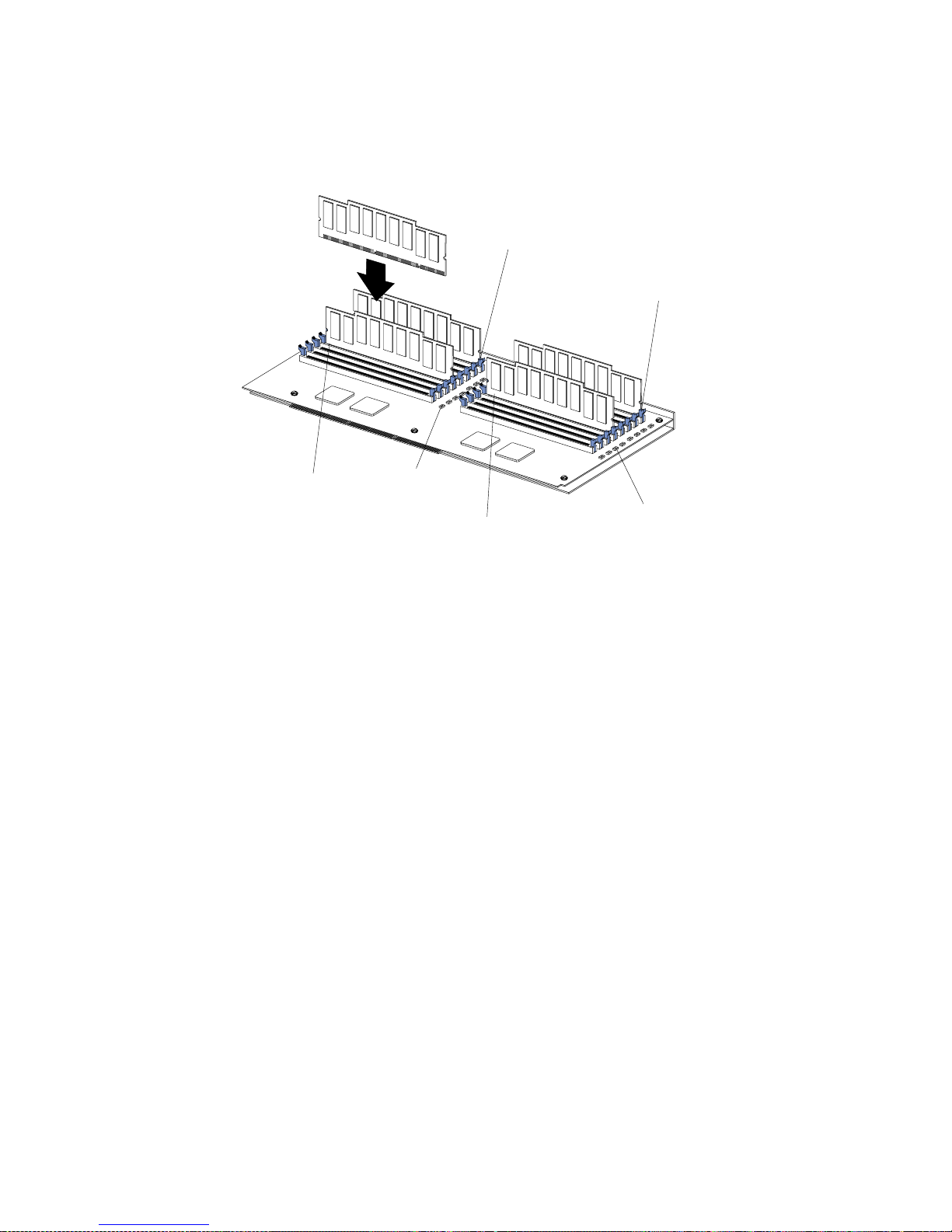
54 IBM® xSeries 350: Use r’s Reference
7. Make sure that the retaining clips are in the closed position. If a gap exists
between the DIMM and the retaining clips, the DIMM has not been properly
installed. In this case, open the retaining clips and remove the DIMM; then,
reinsert the DIM M.
8. Repe at steps 3 through 7 for each additional DIMM that y ou install.
9. Install the memory-board assembly:
a. Hold the memory board assembly, and align it into the card guides and over
the memory-board connector.
Note: When you insert the memory board assembly into the connector, press
on the flat metal projection on the board.
b. Insert the memory board assembly into the connector.
10. If you have other options to install or remove, do so now; otherwise, go to
“Installing the server top cover and bezel” on page 62.
Attention: When you restart the server, the system displays a message indicating that
the memory configur ation has changed.
• If you installed additional memory, start the Configuration/Setup Utility
program and select Save Settings.
• If you just replaced a failed DIMM, you must start the Configuration/Setup
Utility program, select Advanced Setup, select Memory Settings, highlight the
connector or bank of connections that you want to enable, and then select Enable.
• In some memory configurations, the 3-3-3 beep code might sound during POST
followed by a blank display screen. If this occurs and the Boot Fail Count feature
in the Start Options of the Configura tion/Setup Utility is set to Enabled (its
default setting), you must restart the server three times to force the system BIOS
to reset the memory connector or bank of connectors from Disabled to Enabled.
Memory slot 1
Memory slot 5
Memory slot 9
Memory slot 13
Error LEDs
Error LEDs
Page 67

Chapter 5. Installing options 55
Installing a microprocessor
Your server comes with one microprocessor installed on the system board. Your
server supports up to four microprocessors. If you install at least one additional
microprocessor , your server can operate as a symmetric multiprocessing (SMP) server.
With SMP, certain operating systems and application programs can distribute the
processing load among the microprocessors.
Before you begin:
• Review the information in “Before you begin” on page 39.
• Thorough ly review the documentation that comes with the microprocessor, so
that you can determine whether you need to update the server basic
input/output system (BIOS). The latest level of B IOS for your server is available
through the World Wide W eb. See “Chapter 6. Solving problems,” on page 79 for
the World Wide Web addresses.
• Obtain an SMP-capable operating system (optional). For a list of supported
operating systems, see http://www.ibm.com/pc/us/compat/ on the World
Wide Web.
Attention: To avoid damage and ensure proper server operation when you install a
new or an additional microprocessor, use microprocessors that have the same cache
size and type, and the same clock speed. Microprocess or in ternal and external clock
frequencies must be identical.
Notes:
1. To order additional microprocessor options, contact your IBM reseller or IBM
marketing representative.
2. Your server comes with one microprocessor installed in micropr ocessor connector
J34 (slot 1) on the system board an d a terminator card in microprocessor slot 4.
The microprocessor in slot 1 is the startup (boot) microprocessor. The
microprocessor in microprocessor connector J35 is microprocessor 2 (slot 2); the
microprocessor in microprocessor connector J36 is microprocessor 3 (slot 3); and
the microprocessor in micr opro cessor connector J37 is micr opr ocessor 4 ( slot 4). If
more than one microprocessor is installed, the highest-numbered microprocessor
is the microprocessor from which the server will start. The lower-numbered
microprocessors are used as application microprocessors.
3. If you replace the microprocessors in your server with microprocessors of a
different speed, be sure to set the microprocessor -core-frequ ency-selection jumper
block correctly, as described in this section. For a list of supported microprocessor
speeds, see http://www.ibm.com/eserver on the World Wide Web.
4. The server does not support replaceable voltage regulator modules (VRMs).
If you need to install additional microprocessors, install them in the following order:
• Slot 1 (first slot, connector J34)
• Slot 2 (second slot, conn ec tor J35)
• Slot 3 (third slot, connector J36)
• Slot 4 (fourth slot, connecto r J37)
Attention: Your server comes with a terminator car d installed in microprocessor
slot 4. To ensure proper server operation, the terminator card must remain
installed in microprocessor slot 4 until you have installed microprocessors in slots
1 through 3.
Page 68

56 IBM® xSeries 350: Use r’s Reference
The following illustration is a simplified layout of the microprocessor connector
locations and other microprocessor-related components on the system board.
Note: For additional illustrations of the system-board components, see “System
board component locations” on page 31.
To install an additional microprocessor:
Attention: When you handle static-sensitive device s, take precautions to avoid
damage from static electricity. For details on ha nd ling these devices, see “Handling
static sensitive devices” on page 40.
1. Turn off the server and disconnect all power cords and external cables; then,
remove the top cover (see “Removing the server top cover and bezel” on page 41).
2. Determine the slot where the microprocessor is to be installed.
Note: If you are replacing a failed microprocessor, verify that you have selected
the correct microprocessor for replacement. To do this, check the
diagnostic panel that is located under the top cover to see which LED is
on.
3. If you have insta lled microprocessors in slots 1 through 3 and you are now
installing a microprocessor in slot 4, remove the terminator card from the
microprocessor connector. Store the terminator card in a safe place in the staticprotective bag that your new microprocessor comes in; you will need to install it
again if you ever remove the microprocessor.
PCI slot 1
32-bit
33 MHz (J50)
PCI slot 2
64-bit
66 MHz (J51)
PCI slot 3
64-bit
66 MHz (J52)
PCI slot 4
64-bit
66 MHz (J53)
PCI slot 5
64-bit
33 MHz (J54)
PCI slot 6
64-bit
33 MHz (J55)
Microprocessor slot 1 (J34)
Microprocessor slot 2 (J35)
Microprocessor slot 3 (J36)
Microprocessor slot 4 (J37)
Memory board (J40)
Battery
PCI hot-plug
switch card
(J1)
Page 69

Chapter 5. Installing options 57
4. Inst all the microprocessor:
a. Touch the static-pro tective bag con tai ning th e new microprocessor to any
unpainted metal surface on the server; then, remove the microprocessor from
the package.
b. Hold the microprocessor by the open latches, and center the microprocessor
over the microprocessor connector.
Attention: Make sure that the microprocessor is oriented and aligned
correctly before you try to close the latches.
c. Carefully close the latches to seat the microprocessor in the connector.
Terminator card
Latch
Microprocessor
Latch
Page 70
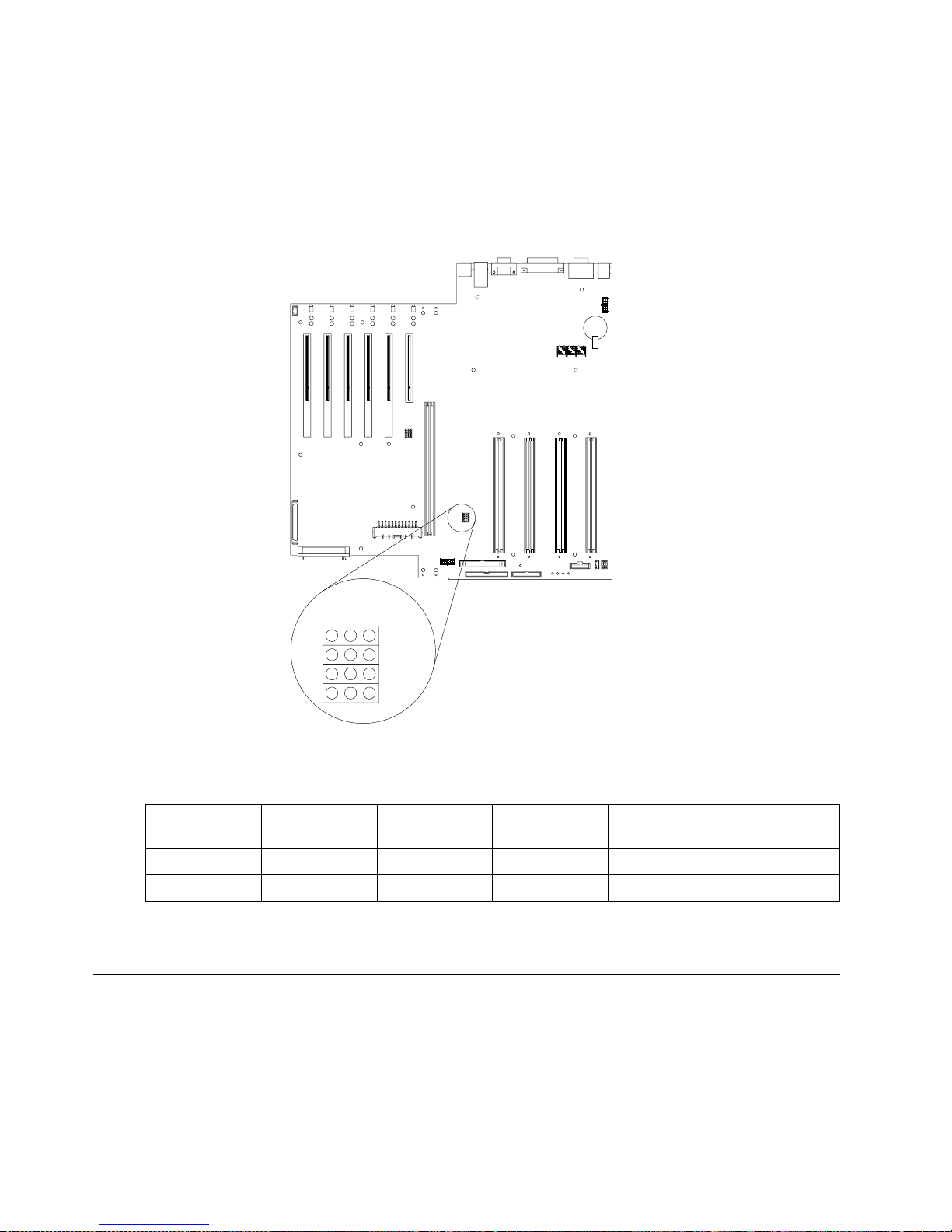
58 IBM® xSeries 350: Use r’s Reference
5. If you replace the microprocessors in your server with microprocessors of a
different speed, set the microprocessor-core-frequency-selection jumper block as
described in Table 5. To ens ure that your server maintains the correct
microprocessor bus-to-core ratio, you must set the microprocessor speed (corefrequency-selection) in the following order, from front to back: J13, J27, J28, and
J29.
Note: See “Changing jumper positions” for additional information on setting
jumpers.
6. If you have other options to install or remove, do so now; otherwise, go to
“Installing the server top cover and bezel” on page 62.
Changing jumper positions
Jumpers on the system board help you to customize the way your server operates.
Your server system board contains three-pin jumper blocks. In some cases, jumper
settings might be combined to define a function.
On a three-pin jumper block, each jumper covers two of the three pins. You can
position the jumper to fit over the center pin and either of the other two pins. To
Table 5. Microprocessor-core-frequency-selection jumper block settings.
Bus Ratio
Core Frequency
(MHz)
J13 J27 J28 J29
Pins 2 and 3 Pins 1 and 2 Pins 2 and 3 Pins 1 and 2 7:1 700/100
Pins 1 and 2 Pins 2 and 3 Pins 2 and 3 Pins 1 and 2 8:1 800/100
Microprocessor
speed jumpers
J13
J27
J28
J29
123
Page 71

Chapter 5. Installing options 59
identify pins 1, 2, and 3 on the system board, see the illustration of the jumper blocks
on the system board on page 58.
To change a jumper position for a three-pin jumper block:
1. Turn off the server; then, disconnect all power cords and external cables.
2. Remove the server cover (see “Removing the server top cover and bezel” on pa ge
41).
3. Lift the jumper straight off the pin block.
4. Align the holes in the bottom of the jumper with the center pin and the pin that
was not covered previously.
5. Slide the jumper fully onto these pins.
6. Reinstall the server cover, and connect the cables (see “Installing the server top
cover and bezel” on page 62).
Installing a hot-swap power supply
Statement 8
CAUTION:
Never remove the cover on a power supply or any part that has the following label
attached.
Page 72

60 IBM® xSeries 350: Use r’s Reference
Hazardous voltage, current, and energy levels are present inside any component
that has this label atta ched. There ar e no service able parts inside these co mponents.
If you suspect a problem with one of these parts, contact a service technician.
Statement 6
CAUTION:
If you install a strain-relief bracket option over the end of the power cord that is
connected to the device, you must connect the other end of the power cord to an
easily accessible power source.
To install an additional hot-swap power supply:
1. Remove the front bezel. See “Removing the server top cover and bezel” on page
41.
2. Remove the filler panel.
3. Move the handle on the power supply to the open position.
4. Slide the power supply into the chassis, and close the handle.
5. Plug one end of each power cord into the corresponding connector on the back of
the server (connectors are number ed 1 thro ugh 3); then, plug the other e nd of each
power cord into a properly grounded electrical outlet.
6. Verify that the dc power light and the ac power light on the power supply are lit,
indicating that the power supply is operatin g properly.
Filler panel
Power supply handlePower supply
DC power light
AC power light
Page 73

Chapter 5. Installing options 61
Replacing a hot-swap fan
Your server comes with six hot-swap fans. You do not need to turn off the power to
the server to replace a hot-swap fan.
Attention: To help ensure proper cooling, replace a fan that has failed within 48
hours.
To replace a hot-swap fan:
1. Remove the top cover (see “Removing the server top cover and bezel” on page
41).
Attention: To ensure proper system cooling, do not leave the top cover off the
server for more than 30 minutes.
2. Grasp the fan handle, and lift the fan out of the server.
3. Slide the replacement fan into the server.
4. Replace the top cover (see “Installing the server top cover a nd be ze l” on page 62).
Completing the installation
To complete you r insta llation, you must reinstall the top cover, reinstall the bezel,
reconnect all the cables that you disconnected earlier and, for certain options, run the
Configuration/Setup Utility program. Follow the instructions in this section.
Attention: To maintain proper cooling and airflow, install the top cover before
turning on the server. Operating the server for extended periods of time (over 30
minutes) with the top cover removed might damage server components.
Hot-swap fans
Page 74
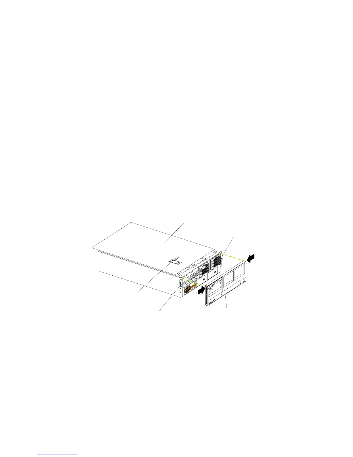
62 IBM® xSeries 350: Use r’s Reference
Note: If you have just plugged the power cords of your server into an electrical
outlet, you will have to wait approximately 20 seconds befo re pressing the
power-control button.
Installing the server top cover and bezel
To install the server top cover and the bezel:
1. Before installing the cover, check that all cables, adapters, and other components
are installed and seated correctly and that you have not lef t loose tools or parts
inside the server.
2. Move the cover-release latch to the open (up) position.
3. Insert the bottom tabs of the top cover into the matching slots in the server
chassis.
4. Close the cover-release latch to pull the top cover forward and lock the top cover
in place.
5. If you disconnected any cables from the back of the server, reconnect the cables;
then, plug the power cords into properly grounded electrical outlets.
Note: If necessary, see“Input/output ports” on page 63 for connector locations.
6. Insert the two tabs on the bottom of the bezel into the matching holes on the
server chassis.
7. Push the top of the bezel toward the server until the two tabs at the top of the
bezel snap into place.
Updating your server configuration
When you start your server for the first time after you add or remove an internal
option or an external SCSI device, you might see a message telling you that the
configuration has changed. The Configuration/Setup Utility program automatically
starts so that you can save the new configuration information. See “Chapter 3.
Configuring your server,” on page 13.
Some options have device drivers that you need to install. See the documentation that
comes with your option for information about installing any required device drivers.
Your server comes with at least one microprocessor installed on the system board. If
you have installed one or more additional microprocessors, your server ca n now
operate as an SMP server. Therefore, you might need to upgrade your operating
Top cover
Release latch
Release latch
Cover release latch
Bezel
Page 75

Chapter 5. Installing options 63
system to support SMP. See “Chapter 4. ServerGuide,” on page 23 and your
operating-system documentation for add itional information.
If your server ha s a Serve RAID adapt er in sta lled and yo u have i nstal led or r emoved a
hard disk drive, see the documentation that comes with your ServeRAID adapter for
information about reconfiguring your disk a rrays.
Connecting external options
Before you begin:
• Review “Before you begin” on page 39.
• Read the documentation that comes with your options.
You can attach externa l options to the input/output (I/O) connectors on the rear of
your server. (See “Input/output ports” for more information.)
To attach an external device:
1. Turn off the server and all attached devices.
2. Follow the instructions that come with the option to prepare it for installation and
to connect it to the server.
Note: If you are attaching an external SCSI device, see “Ult ra160 SCSI ports” on pa ge
67 for information about SCSI cabling and SCSI IDs.
Input/output ports
This section provides information about the input/output (I/O) connectors on the
rear of your server. These connectors include the following:
• One parallel port
• One video port
• One keyboard port
• One auxiliary-de v ice (pointin g device) port
• Two Ultra160 SCSI ports
• Two serial ports
• Tw o Universal Serial Bus (USB) ports
• One Ethernet port
• Three communication ports dedicated to the Advanced System Management
processor
Page 76

64 IBM® xSeries 350: Use r’s Reference
The following illustration shows the I/O ports on the rear of your server.
Parallel port
Your server has one parallel port. This port supports three standard Institute of
Electrical and Electronics Engin eers (IEEE) 1284 modes of operati on: Standard Paral lel
Port (SPP), Enhanced Parallel Port (EPP), and Extended Capability Port (ECP).
Viewing or changing the parallel-port
assignments
You can use the built-i n Configuration/Setup Utility program to configure the
parallel port as bidirectional, that is, so that data can be both read from and written to
a device. In bidirectional mode, the server supports the ECP and EPP modes.
To view or change the parallel-port assignment:
1. Restart the server and watch the monitor screen.
2. When the message Press F1 for Configuration/Setup appears, press F1.
Note: The Devices and I/O Ports choice appears only on the full con fi guration
menu. If you set two levels of passwords, you must type the administrator
password to access the full configuration menu.
3. From the main menu, select Devices and I/O Ports; then, press Enter.
4. Select the parallel port; then, use the arrow keys to advance through the available
settings.
Note: When you configure the parallel port as bidirectional, use an IEEE 1284-
compliant cable. The maximum length of the cable must not exceed 3
meters (9.8 feet).
5. Select Save Settings; then, sele ct Exi t Se tup to exit from the Configuration/Setup
Utility main menu.
Advanced System Management
Interconnect port A
Advanced System Management
Interconnect port B
Video
Management port C
Mouse
Keyboard
Serial B
Serial A
Parallel
Ethernet
USB 1
USB 2
Page 77

Chapter 5. Installing options 65
The following table shows the pin-number assignments for the 25-pin, female D-shell
parallel port on the rear of your server.
Video port
Your server comes with an integrated super video graphics array (SVGA) video
controller. This controller is not removable, but you can disable it by installing a PCI
video adapter.
Note: If you install a PCI video adapter, the server BIOS will automatically disable
the integrated video controller.
Table 6. Parallel-port connector pin-number assignments.
Pin I/O SPP/ECP Signal EPP Signal
1 O -STROBE -WRITE
2 I/O Data 0 Data 0
3 I/O Data 1 Data 1
4 I/O Data 2 Data 2
5 I/O Data 3 Data 3
6 I/O Data 4 Data 4
7 I/O Data 5 Data 5
8 I/O Data 6 Data 6
9 I/O Data 7 Data 7
10 I -ACK -ACK
11 I BUSY -WAIT
12 I PE (paper end) PE (paper end)
13 I SLCT (select) SLCT (select)
14 O -AUTO FD (feed) -AUTO FD
15 I -ERROR -ERROR
16 O -INIT -INIT
17 O -SLCT IN -SLCT IN
18 - Ground Ground
19 - Ground Ground
20 - Ground Ground
21 - Ground Ground
22 - Ground Ground
23 - Ground Ground
24 - Ground Ground
25 - Ground Ground
13
1
25
14
Page 78
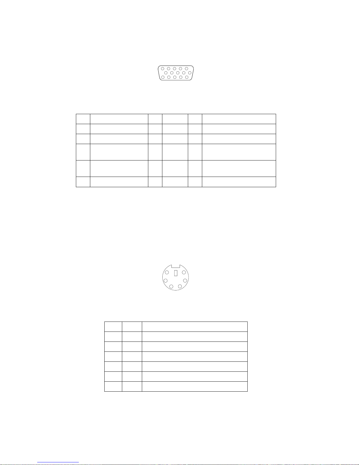
66 IBM® xSeries 350: Use r’s Reference
The following table shows the pin-number assignments for the 15-pin analog video
connector on the rear of your server.
Keyboard port
There is one keyboard port on the rear of your server.
Note: If you attach a standard (non-U SB) keyboard to the keyboard port, the USB
ports and devices will be disabled during the power-on self-test (POST).
The following table shows the pin-number a ssignments for the keyboard port on the
rear of your server.
Table 7. Video-port connector pin-number assignments.
Pin Signal Pin Signal Pin Signal
1Red 6Ground11Not connected
2 Green or monochrome 7 Ground 12 DDC SDA
3 Blue 8 Ground 13 Horizontal s ynchronization
(Hsync)
4 Not connected 9 +5 V dc 14 Vertical synchronization
(Vsync)
5 Ground 10 Ground 15 DDC SDL
Table 8. Keyboard connector pin-number assignments .
Pin I/O Signal
1I/OData
2N/AReserved
3N/AGround
4 N/A +5 V dc
5 I/O Keyboard clock
6N/AReserved
1
5
1115
6
4
2
1
3
5
Page 79

Chapter 5. Installing options 67
Auxiliary-device (pointing device) port
The system board has one auxiliary-device port that supports a mouse or other
pointing device.
The following table shows the pin-number assignments for the auxiliary-device port
on the rear of your server.
Ultra160 SCSI ports
Your server has an integrated dual-channel Ultra160 small computer system interface
(SCSI) controller. Th is controller supports two independent Ultra 160/m SCSI
channels: one internal and one external. Each of these channels supports up to 15
SCSI devices. In addition, this controller uses:
• Double-transition clocking to achieve high transfer rates
• Domain-name validation to negotiate compatible data-transfer speeds with each
device
• Cyclic redundancy checking (CRC), instead of parity checking, to significantly
improve data reliability
• An active terminator on the system board for SCSI bus termination
The server comes with two SCSI cables; each cable is connected to one of the SCSI
channels. One SCSI cable connects the internal SCSI channel connector to the
standard hot-swap-drive backplane. The other SCSI cable is connected to the external
SCSI channel connector; however, this connector is cabled for internal use. If you
want to use the external L VD S CSI channel connector to connect external SCSI devices
to the server, remove the knockout on the rear of the server and install the LVD SCSI
cable that comes with the server.
Note: If you install a PCI RAID adapter to configure and manage the internal hot-
swap drives, you must move the SCSI cable from the system-board SC SI
connector to an internal channel connector on the RAID adapter. See “Cabling
the ServeRAID adapter” on page 44 for additional information.
Table 9. Auxiliary-device connector pin-number
assignments.
Pin Signal
1Data
2Not connected
3Ground
4+5 V dc
5Clock
6Not connected
6
4
2
1
3
5
Page 80

68 IBM® xSeries 350: Use r’s Reference
SCSI cabling requirements
If you plan to attach external SCSI devices, you must order additional SCSI cables. To
select and order the correct cables for use with external devices, contact your IBM
reseller or IBM marketing representative.
For information about the maximum length of SCSI cable between th e terminated
ends of the cable, refer to the ANSI SCSI standards. Adhering to these standards will
help ensure that your server operates properly.
Setting SCSI IDs
Each SCSI device that is connected to a SCSI controller must have a unique SCSI ID.
This ID enables the SCSI controller to identify the device and ensure that different
devices on the same SCSI channel do not attempt to transfer data simultaneously.
SCSI devices that are connected to different SCSI channels can have duplicate SCSI
IDs. The following table lists the SCSI IDs for devices that are connected to one
channel. Note that the hot-swap hard disk drive bay numbers are from bottom to top.
The hot-swap-drive backplane controls the SCSI IDs for the internal hot-swap drive
bays. However, when you attach a SCSI device to the external SCSI connector, you
must set a unique ID for the device. Refer to the information that is provided with the
device for instructions to set its SCSI ID.
SCSI connector pin-number assignments
The following table shows the pin-number assignments for the 68-pin SCSI
connectors.
Table 10. SCSI IDs for hot-swap hard disk
drives and backplanes.
Standard Optional
Drive bay 1:
SCSI ID 0
Drive bay 4:
SCSI ID 12
Drive bay 2:
SCSI ID 1
Drive bay 5:
SCSI ID 13
Drive bay 3:
SCSI ID 2
Drive bay 6:
SCSI ID 14
Backplane: SCSI
ID 8
Backplane: SCSI
ID 9
Table 11. 68-pin SCSI connector pin-number assignments.
Pin Signal Pin Signal
1 +Data 12 35 -Data 12
2 +Data 13 36 -Data 13
3 +Data 14 37 -Data 14
4 +Data 15 38 -Data 15
34
1
68
35
Page 81

Chapter 5. Installing options 69
Serial ports
Your server has two standard serial ports: serial port A and serial port B. The
operating system can use and share both serial ports; however, the integrated
Advanced System Management processor can use and share only serial port A.
Some application programs require specific ports, and some modems function
properly only at certain communication port addresses. You might need to use the
Configuration/Setup Utility program to ch ange communication port address
assignments to prevent or resolve address conf licts.
Viewing or changing the serial-port assignments
To view or change the serial-port assignments:
1. Restart the server and watch the monitor screen.
2. When the message Press F1 for Configuration/Setup appears, press F1.
3. From the main menu, select Devices and I/O Ports; then, press Enter.
5 +Data P1 39 -Data P1
6 +Data 0 40 -Data 0
7 +Data1 41 -Data 1
8 +Data 2 42 -Data 2
9 +Data 3 43 -Data 3
10 +Data 4 44 -Data 4
11 +Data 5 45 -Data 5
12 +Data 6 46 -Data 6
13 +Data 7 47 -Data 7
14 +Data P 48 -Data P
15 Ground 49 Ground
16 DIFFSENS 50 Ground
17 Term power 51 Term power
18 Term power 52 Term power
19 Reserved 53 Reserved
20 Ground 54 Ground
21 +Attention 55 -Attention
22 Ground 56 Ground
23 +Busy 57 -Busy
24 +Acknowledge 58 -Acknowledge
25 +Reset 59 -Reset
26 +Message 60 -Message
27 +Select 61 -Select
28 +Control/Data 62 -Control/Data
29 +Request 63 -Request
30 +Input/Output 64 -Input/Output
31 +Data 8 65 -Data 8
32 +Data 9 66 -Data9
33 +Data 10 67 -Data 10
34 +Data 11 68 -Data 11
Table 11. 68-pin SCSI connector pin-number assignments.
Pin Signal Pin Signal
Page 82

70 IBM® xSeries 350: Use r’s Reference
Note: The Devices and I/O Ports choice appears only on the full con fi guration
menu. If you set two levels of passwords, you must type the administrator
password to access the full configuration menu.
4. Select the serial port; then, use the arrow keys to advance through the available
settings.
5. Select Save Settings; th en, select Exi t Setup to exit from the Configuration/Setup
Utility main menu.
Serial-port pin assignments
The following table shows the pin-n umber assignments for the 9-pin, male D-shell
serial-port connectors on the rear of your server. These pin-number assignments
conform to the industry standard.
Universal Serial Bus ports
Your server has two Universal Serial Bus (USB) ports, which are configured
automatically. USB is a serial interface standard for telephony and multimedia
devices. It uses Plug and Play technology to determine the type of device that is
attached to the connector.
Notes:
1. If you attach a standard (non-USB) keyboard to the keyboard connector, the USB
ports and devices will be disabled during the power-on self-test (POST).
2. If you install a USB keyboard that has a mouse port, the USB keyboard emulates a
mouse and you will not be able to disable the mouse settings in the
Configuration/Setup Utility program.
USB cables and hubs
You need a 4-pin cable to connect devices to USB 1 or USB 2. If you plan to attach
more than two USB devices, you must use a hub to connect the devices. The hub
provides multiple connectors for attaching additional external USB devices.
USB technology provides up to 12 megabits-per-second (Mbps) speed with a
maximum of 127 external devices and a maximum signal distance of five meters (16
ft) per segment.
Table 12. Serial-port connectors pin-number assignments.
Pin Signal Pin Signal
1 Data carrier detect 6 Data set ready
2Receive data 7Request to send
3Transmit data 8Clear to send
4 Data terminal ready 9 Ring indicator
5 Signal ground
1
5
69
Page 83

Chapter 5. Installing options 71
USB-port pin assignments
Each USB port has an external connector on the rear of the server for attaching USB
compatible devices.
The following table shows the pin-number assignments for the USB ports on the rear
of your server.
Ethernet port
Your server comes with an integrated Ethernet controller. This controller provides an
interface for connecting to 10-Mbps or 100-Mbps networks and provides full-duplex
(FDX) capability, whic h enables simultaneous transmission and reception of data on
the Ethernet local area network (LAN).
To access the Ethernet port, connect a Category 3, 4, or 5 unshielded twisted-pair
(UTP) cable to the RJ-45 connector on the rear of your server.
Note: The 100BASE-TX Fast Ethernet standard requires that the cabling in the
network be Category 5 or higher.
The Ethernet (RJ-45) connector has two lights. The Ethernet-link sta tus light is on the
left. When this green light is on, there is an active connection on the Ethernet port.
The Ethernet transmit/receive activity light is on the right. When this amber light is
on, there is activity between the server and the network. These lights have the same
functions as the Ethernet-link status light and the Ethernet transmit/receive activity
light on the information panel (see “Inform ation panel” on page 8).
Configuring the Ethernet controller
When you connect your server to the network, the Ethernet controller automatically
detects the data-transfer rate (10Mbps or 100Mbp s) on the network and then sets the
controller to operate at the appropriate rate. That is, the Ethernet controller wi ll
adjust to the network data rate, whether the data rate is standard Ethernet (10BASET), Fast Ethernet (100BASE-TX), half duplex (HDX), or full duplex (FDX). Th e
controller supports half-duplex (HDX) and full-duplex (FDX) modes at both speeds.
The Ethernet controller is a PCI Plug and Play device. You do not need to set any
jumpers or configure the controller for your operating system before you use the
Ethernet controller. However, you must install a device driver to enable your
operating system to address the Ethernet controller. The device drivers are provided
on the ServerGuide CDs.
Failover for redundant Ethernet
The IBM Netfinity 10/100 Fault Tolerant Adapter is an optional redundant network
adapter that you can install in your server. If you install this adapter and connect it to
the same logical LAN segment as the primary Ethernet controller, you can configure
Table 13. USB-port connector pin-number
assignments.
Pin Signal
1VCC
2-Data
3+Data
4Ground
Page 84

72 IBM® xSeries 350: Use r’s Reference
the server to support a failover function. You can configure either the integrated
Ethernet controller or the network adapter as the primary Ethernet controller. In
failover mode, if the primary Ethernet controller detects a link failure, all Ethe rnet
traffic associated with it is switched to the redundant (secondary) controller. If the
appropriate device drivers are installed, this switching occurs without any user
intervention. When the primary link is restored to an operational state, the Ethernet
traffic switches back to the primary Ethernet controller. The switch back to the
primary Ethernet controller can be automatic or ma nually controlled, depending on
the setup and operating system.
Note that only one controller in the redundant pair is active at any given time. For
example, if the primary Ethernet controller is active, the secondary Ethernet controller
cannot be used for any other network operation.
Note: Your operating system determines the maximum number of IBM 10/100 Fault
Tolerant Ada pters that you can install in your server. See the documentation
that comes with the adapter for more information.
Considerations when combining failover and hot-plug
functions: If your operating system supports hot-plug PCI adapters and the optional
redundant network adapter is installed in a hot-plug PCI slot, you can replace the
network adapter without powering off the server — even if it is the primary Ethernet
controller. Disconnecting the Ethernet cable from the primary Ethernet controller will
cause the Ethernet traffic to switch automatically to the secondary Ethernet contr oller .
This can be very useful if a faulty adapter causes a network problem, or if you want to
upgrade the primary adapter hardware.
Note: If you replace the primary adapter while the Ethernet traffic is being handled
by the secondary Ethernet controller, the traffic does not automatically switch
back to the primary adapter when the primary adapter comes back online. See
“Configuring for failover”.
Configuring for failover: The failover feature is supported by Microsoft Windows
NT Server and Novell IntraNetWare. The setup required for each operating system
follows.
Windows NT Server:
IBM offers hot-plug support for Windows NT Server Version 4.0. Failover can work
in conjunction with hot-plug support or independently. If you are not using hot-plug
support, go to “Windows NT Server failover setup” on page 73.
Windows NT Server hot-plug setup:
IBM Hot Plug PCI for Windows NT Server 4.0 package is available for download at
http://www.pc.ibm.com/support on the World Wide Web.
Type the brand type of server in the Server field, click Downloadable files, and look
for Hot Plug. The IBM Hot Plug PCI for Windows NT Server 4.0 package uses the
Intel Desktop Management Interface (DMI) to control hot-plug support f or the
Ethernet controllers. The Ethernet controller in your computer is DMI compliant.
Download and install the following software in the order listed:
1. IBM Netfinity PCI Hotplug for Windows NT 4.0 Failover DMI Agent
2. IBM Netfinity PCI Hotplug for Windows NT 4.0 Solution
3. IBM Netfinity 10/100 Fault Tolerant Adapter device drivers
Note: The order of installation is important. You must install the IBM Netfinity Hot
Plug for Windows NT Server 4.0 package before you install the IBM 10/100
Fault T olerant Adapter device drivers. If you install the adapter device drivers
before the PCI Hot Plug Solution package, the adapter device drivers will not
recognize the hot-plug code. This happens because the adapter device drivers
Page 85

Chapter 5. Installing options 73
check the NT registry for the Hot Plug package only during installation. If the
PCI Hot Plug Solution package is added after the adapter device drivers are
installed, the adapter must be r emoved and a dded again for it to detect the PCI
Hot-Plug Solution code.
To install the IBM PCI Hotplug for Win dows NT 4.0 Failover DMI Agent:
1. Downloa d the IBM PCI Hotplug for Windows NT 4.0 Failover DMI Agent file
from the xSeries Support Web page, and extract the files onto a dis kette.
2. Insert the diskette into the diskette drive.
3. From the Start menu, click Run.
4. Type A:\SETUP.EXE in the Open field.
5. Click OK. The Setup wizard opens.
6. Follow the instructions in the Setup wizard until the program is installed.
7. Restart the server.
To install the IBM PCI Hotplug for Windows NT 4.0 Solution package:
1. Downloa d the IBM PCI Hotplug for Wind ows NT 4.0 Solution file from the
xSeries Support web page and extract the files onto a diskette.
2. Log on to Windows NT Server as a user in the Administrator group.
3. Insert the diskette into the diskette drive.
4. From the Start menu, select the Run option.
5. Type A:\SETUP.EXE in the Open field.
6. Click OK. The Setup wizard opens.
7. Follow the instructions in the Setup wizard until the program is installed.
Windows NT Server failover setup:
To install the IBM 10/100 Fault Tolerant Adapter device drivers:
1. Add the redundant network adapter accor ding to the instructions that come with
the adapter.
2. Use the ServerGuide CDs to install the AMD PCNet Ethernet Family adapter
device driver.
3. Do not select the Grouping check box at this point; you must first restart the
server.
4. From the Windows NT Server desktop, double-click Control Panel, then doubleclick the Network icon, and then click the Adapters tab.
5. Select one of the ad apters that will be in the redundant pair, and then click the
Properties... button.
6. Select the Grouping check box. This will show the possibl e combinations for
redundant pairs.
7. Select the adapter pair you want, and then click OK. Note that the integrated
Ethernet controller is located at PCI C.
Two options are available for recovering from a failover condition. The options
are determined by the Enable for DMI / Hot Swap Support checkbox. If the IBM
Hot Plug PCI for Windows NT Server 4.0 package is installed, this check box will
appear at the bottom of the Adapter Properties panel. If you do not have the IBM
Hot Plug PCI for Windows NT Server 4.0 package installed on your server, you
will not see the Enable for DMI / Hot Swap Support checkbox.
If the Enable for DMI / Hot Swap Support check box is not checked or is not
present, traffic will automatically switch back to the primary adapter when the
Page 86

74 IBM® xSeries 350: Use r’s Reference
primary link status is re stored. In this mode, the adapter cannot be hot-swapped.
If the IBM Netfinity Hot Plug PCI for Windows NT Server 4.0 package is installed,
select the Enable for DMI / Hot Swap Support check box.
If the Enable for DMI / Hot Swap Support check box is selected, traffic will
remain on the secondary adapter until you direct it to return to the primary
adapter. You can do this after the hot-swap replacement of the primary adapter or
by using the DMI interface.
8. Click Close to exit from the network setup.
When you restart the server, the failover function will be in effect.
If a failover occurs, a message is written to the W indows NT Event Log. In addition, if
the Enable for DMI / Hot Swap Support check box is selected, a DMI alert will also
be generated.
IntraNetWare:
The IBM PCI Hot Plug System Bus Driver Diskette for Novell Netware V4.41, V4.42,
and V5.0 is available for download from the IBM Web site at
http://www.pc.ibm.com/support.
The failover function is now enabled. If a failover occurs:
• The operating system console generates a message.
• The custom counters fo r the device driver contain variables that define the state of
the failover function and the location of the redundant pair. You can use the
NetWare Monitor to view the custom counters.
Note: If the primary adapter was replaced while the Ethernet traffic was being
handled by the secondary Ethernet controller, the traffic does not
automatically switch back to the primary adapter when the primary adapter
comes back online. In this case, issue the command:
LOAD d:\path\PCNTNW SCAN
where d and path are the drive and path where the device driver is located.
This command causes the device driver to locate the primary adapter and
switch the Ethernet traffic to it.
Page 87

Chapter 5. Installing options 75
Ethernet port
The following table shows the pin-number assignments for the RJ-45 port. These
assignments apply to both 10BASE-T and 100BASE-TX devices.
Advanced System Management ports
Your server has three communication ports that are dedicated to the Advanced
System Management processor. One port uses a standard D-shell serial-port
connector, connector C. The other two ports, which are used for the ASM
Interconnect function, use a dual RJ-45 connector.
You can attach a dedicated modem to the D-shell system-management connector on
the rear of your server to communicate with the integrated Advanced System
Management pr o cess o r.
The ASM interconnect function uses the RJ-45 system-management connectors. This
function enables you to connect the Advanced System Management processors of
several rack-mounted servers so that they can communicate with each other in halfduplex mode.
Table 14. Ethernet RJ-45 connector pin-number
assignments.
Pin Signal Pin Signal
1 +Transmit data+ 5 Not connected
2 –Transmit data 6 –Receive data3 +Receive data+ 7 Not connected
4 Not con n ec ted 8 Not co nne c t e d
Page 88

76 IBM® xSeries 350: Use r’s Reference
The following illustration sho ws the connectors and lights for the Advanced System
Management In t erconnect board.
Cabling the server
The following illustration shows the cabling for a typical server configuration.
Detailed cabling instructions are given in “Appendix 7. Rack installation
instructions,” on page 137.
Notes:
1. The illustrations in this document might differ slightly from your hardware.
2. Refer to the documenta tion that comes with your options for additional cabling
instructions. It might be easier for you to route any cables before you install
certain options.
Serial port Advanced System Management
Interconnect connectors
System board connectorService processor
error
Power LED
Page 89
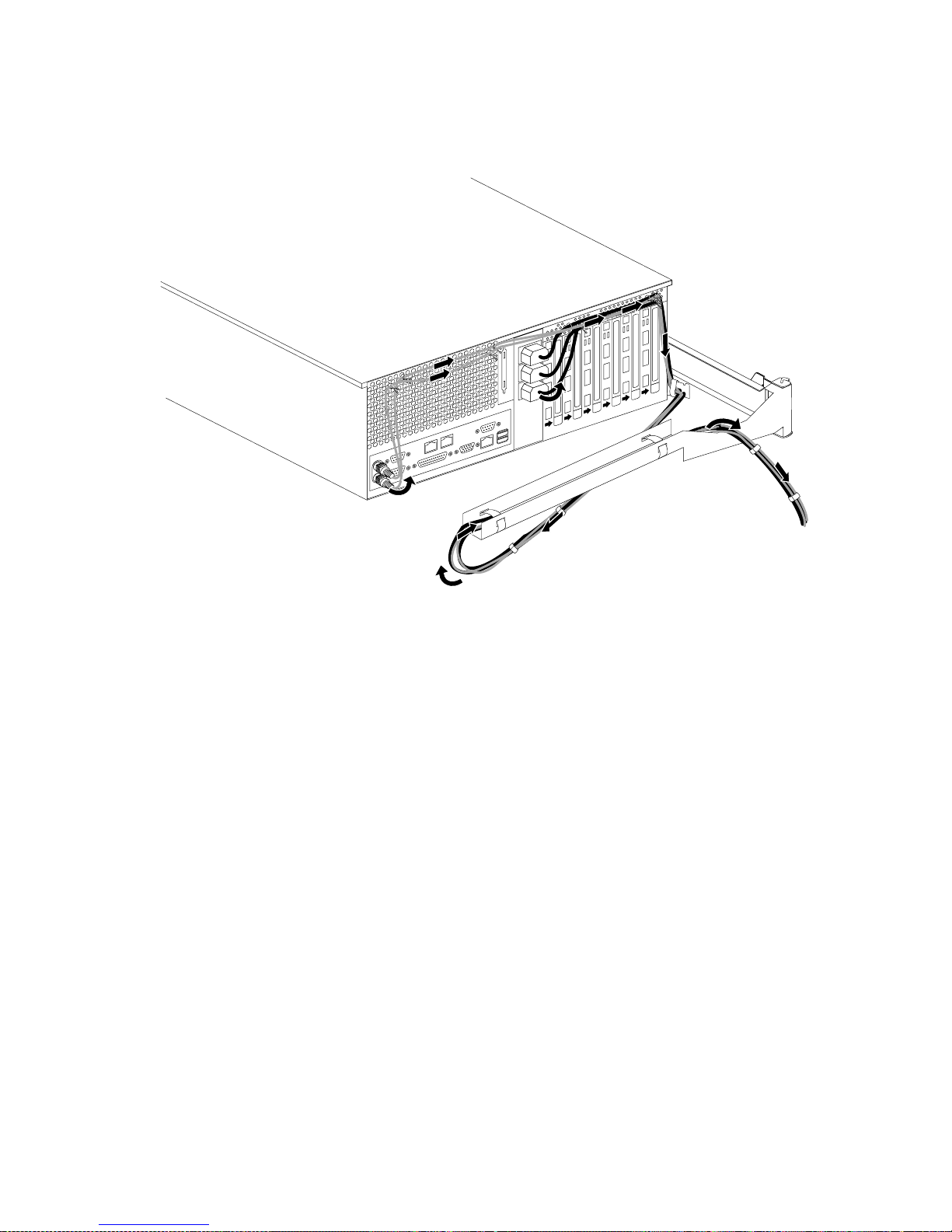
Chapter 5. Installing options 77
3. Cable identifiers are printed on the cables that come with your server and
options. Use these identifiers to connect the cables to the correct connectors. For
example, the hard disk drive cables are labeled HDD.
Page 90

78 IBM® xSeries 350: Use r’s Reference
Page 91

© Copyright IBM Corp. 2001 79
Chapter 6. Solving problems
This section provides basic troubleshooting information to help you resolve some
common problems that might occur with your server.
If you cannot locate and correct the problem using the information in this section, see
“Getting help, service, and information” on page 128 for more information.
Diagnostic tools overview
The following tools are available to help you identify and resolve hard ware-related
problems:
• POST beep codes, error messages, and error logs
The power-on self-test (POST) generates be ep codes and messages to indicate
successful test completion or the detection of a problem. See “POST” on page 81
for more information.
• Diag nostic prog ra ms and error messages
The server diagnostic programs are stored in upgradable read-only memory
(ROM) on the processor board. These program s are the primary method of testing
the major components of your server. See “Diagnostic programs and error
messages” on page 95 for more information.
• Light Path Diagnostics
Your server has light-emitting diodes (LEDs) to help you identify problems with
server components. These LEDs are part of the Light Path Diagnostics that are
built into your server. By following the path of lights, you can quickly identify the
type of system error that occurred. See “Light Path Diagnostics” on page 109 for
more information.
• Troubleshooting charts
These charts list problem symptoms, along with sugges ted steps to correct the
problems. See the “Troubleshooting charts” on page 112 for more information.
• Customized support page
You can create a customized support page that is specific to your hardware,
complete with frequently asked questions, parts information, technical hints and
tips, and downloadable files. In addition, you can choose to receive electronic
mail (e-mail) notifications w henever new information becomes available about
your registered products.
After you register and create a profile for your IBM products, you can diagnose
problems using the IBM Online Assistant an d you can participate in the IBM
discussion forum. For more detailed information about registering and creating a
customized profile for your IBM products, visit the following addresses on the
Web:
— http://www.ibm.com/pc/register
— http://www.ibm .com /pc/ support
Page 92

80 IBM® xSeries 350: Use r’s Reference
S
erver Support
After you register and profile, you will be able to:
• Diagnose problems using the IBM Online Assistant
• Participate in the IBM discussion forum
• Receive e-mail notifications of technical updates
related to your profiled products
Register at:
Profile at:
http://www.ibm.com/pc/register
http://www.ibm.com/pc/support
Register and profile your server
Yes
No
No
Phone an
IBM HelpCenter
Use the troubleshooting
information provided with
your server to determine
the cause of the problem
and the action to take.
Flash the latest levels of BIOS,
service processor, diagnostics,
and RAID code.
You can download this code at:
http://www.ibm.com/pc/support
No
No
Yes
Yes
Yes
Check all cables for loose connections
and verify that all optional devices you
installed are on the ServerProven list.
You can view the ServerProven list at:
®
http://www.ibm.com/pc/compat
Server working
properly?
Problem
solved?
Problem
solved?
Problem
solved?
You can view a list of
IBM HelpCenter phone numbers at:
®
http://www.ibm.com/pc/support
Page 93

Chapter 6. Solving problems 81
POST
When you turn on the server, it perfor ms a series of tests to check the operation of
server components and some of the options that are installed in the server. This series
of tests is called the power-on self-test or POST.
If POST finishes without detecting any problems, a single beep sounds, and the first
screen of your operating system or application program appears.
If POST detects a problem, more than one beep sounds, and an error message appears
on your screen. See “POST beep code descriptions” and “POST error messages” on
page 84 for more information.
Notes:
1. If you have a power-on password or administrator password set, you must type
the password and press Enter, when prompted, before POST will continue.
2. A single problem might cause several error messages. When this occurs, work to
correct the cause of the first error message. After you correct the cause of the first
error message, the other error messages usually will not occur the next time you
run the test.
POST beep code descriptions
Beep codes are sounded in a series of long and short beeps.
The possible types of beep codes that your server might emit include the following:
No beeps
If no beep occurs after your server completes POST (that is, after the System
POST Complete (OK) light on the operator information panel is illuminated),
call for service.
Continuous beep
Your startup (boot) microprocessor has failed, the system board, or speaker
subsystem might contain a failing component. If the system continues
through POST with no errors, call for service. If no video appears, the startup
processor has failed; replace the startup processor.
One short beep
One beep indicates that your server successfully completed POST. POST
detected no configuration or functional errors. One beep also occurs after
your server completes POST if you type an incorrect power-on password.
Two short beeps
POST encountered an error. The Co nfiguration/Setup Utility program will
display additional information; follow the instructions that appear on the
screen. See “POST error messages” on page 84 for descriptions of the text
messages that might appear.
Three short beep s
A system memory error has occurred. This combination occurs only if the
video basic input/output system (BIOS) cannot display the error message.
Replace the failing memory module.
Page 94

82 IBM® xSeries 350: Use r’s Reference
Repeating short beeps
The system board might contain a failing component, your keyboard might
be defective, or a key on the keyboard might be stuck. Ensure that:
• Nothing is resting on the keyboard and pressing a key.
• No key is stuck.
• The keyboard cable is connected correctly to the keyboard and to the
correct connector on the server.
Running the diagnostic tests can isolate the server component that failed, but
you must have your system serviced. If the error message remains, call for
service.
Note: If you just connected a new mouse or other pointing device, turn off
the server and disconnect that device. Wait at least 5 seconds; then,
turn on the server. If the error message goes away, replace the device.
One long and one short beep
POST encountered an error on a video adapter. If you are using the
integrated video controller, call for service. If you are using an optional video
adapter, replace the failing video adapter.
One long and two short beeps
A video I/O adapter ROM is not readable, or the video subsystem is
defective. If you hear this beep combination twice, both the system board and
an optional video adapter have failed the test. This beep combination might
also indicate that the system board contains a failing component.
One long and three short beeps
The system-board video subsystem has not detected a monitor conn ection to
the server. Ensure that the monitor is connected to the server. If t he problem
persists, replace the monitor.
Two long and two short beeps
POST does not support the optional video adapter. This beep combination
occurs when you install a video adapter that is incompatible with your server.
Replace the optional video adapter with one that the server supports, or use
the integrated video controller.
Page 95

Chapter 6. Solving problems 83
POST beep codes
In addition to the beep codes that are described in “POST beep code descriptions” on
page 81, your computer might emit beep codes that are described in the following
table. The numbers and hyphens describe the sequence of beeps and pauses. For
example, a 1-2-3 beep code is one beep, a pause, two consecutive beeps, another
pause, and three more consecutive beeps.
Table 15. POST beep codes.
Beep code Description Action
1-1-2 Microprocessor register test has failed. Call for service.
1-1-3 CMOS write/read test has failed.
1-1-4 BIOS ROM checksum has failed.
1-2-1 Programmable Interval Timer test has failed.
1-2-2 DMA initialization has failed.
1-2-3 DMA page register write/read test has failed.
1-4-3 Interrupt vector loading test has failed.
2-1-1 Secondary DMA register test has failed.
2-1-2 Primary DMA register test has failed.
2-1-3 Primary interrupt mask register test has failed.
2-1-4 Secondary interrupt mask register test has failed.
2-2-1 Interrupt vector loading has failed.
2-2-2 Keyboard controller test has failed.
2-2-3 CMOS power failure and checksum checks have failed.
2-2-4 CMOS configuration information validation has failed.
2-3-2 Screen memory test has failed.
2-3-3 Screen retrace tests have failed.
2-3-4 Search for video ROM has failed.
2-4-1 Screen test indicates the screen is operable.
3-1-1 Timer tick interrupt test has failed.
3-1-2 Interval timer channel 2 test has failed.
3-1-3 RAM test has failed above address hex 0FFFF.
3-1-4 Time-of-Day clock test has failed.
3-2-1 Serial port test has failed.
3-2-2 Parallel port test has failed.
3-2-3 Math Coprocessor test has failed.
3-2-4 Comparison of CMOS memory size against actual has
failed.
2-3-1
3-3-2
Screen initialization has failed.
I2C bus has failed.
T u rn of f th e server, unplug all power cord s,
and reconnect all power cords; then, restart
the server. If the problem persists, call for
service.
Page 96

84 IBM® xSeries 350: Use r’s Reference
POST error messages
The following tables provide information about the POST error messages that can
appear during startup.
1-2-4 RAM refresh verification has failed. Reseat the memory modules or install a
memory module. If the problem persists,
call for service.
Attention: In some memory
configurations, the 3-3-3 beep code might
sound during POST followed by a blank
display screen. If this occurs and the Boot
Fail Count feature in the Start Options of
the Configuration/Setup Utility is set to
Enabled (its default setting), you must
restart the server three times to force the
system BIOS to reset t he memory conn ector
or bank of connectors from Disabled to
Enabled.
1-3-1 First 64 Kb RAM test has failed.
1-3-2 First 64 Kb RAM parity test has failed.
3-3-1 A memory size mismatch has occurred.
3-3-3 No memory has been detected in the system.
Table 16. POST erro r messa ges .
POST message Description
062 The server failed to start on three consecutive attempts.
All caches are disabled. Repeatedly turning the server on and then off or resetting the server
might cause this problem.
Action: Start the Configuration/Setup Utility program and verify that all settings are correct.
Use the Cache Control selectio n in the Advanced Setup menu of th e
Configuration/Setup Utility program to enable the caches.
If the problem persists, call for service. When the problem is corrected, be sure to enable the
caches.
101
102
106
An error occurred duri ng th e syste m boa rd and microprocessor test.
Action: Call for service.
114 An adapt er read-only memory (ROM) error occurred.
Action: Remove the options. If you can start the server without the options installed, reinstall
each option one at a time and retest after each is reinstalled. When an option fails,
replace it.
If you cannot isolate and correct the problem, call for service.
Table 15. POST beep codes.
Page 97

Chapter 6. Solving problems 85
129 An error was detected in the L1 cache of one of th e microprocessors.
Action: 1. If you just installed a micropr ocessor, verify that the micropr ocessor is ins talled and
seated correctly.
2. If the problem persists, check to see if the system has isolated the problem to a
microprocessor:
• If the system error light on the operator information panel is on, check the
diagnostic panel to see if the CPU LED is on. S ee “System b oard LE D location s
and diagnostic LED panel” on page 36 to identify the diagnostic panel and the
LED. If it is on, check the microprocessor-error lights next to the
microprocessor sock ets.
— If a microprocessor-error light is on, run the diagnostic program for the
microprocessor that is indicated by the LED. If the tests fail, replace the
indicated microproc ess or.
— If the microprocessor tests do not fail, call for service.
• If no error LED is on, the error logs in the Configuration/Setup Utility
program might provide additional informat ion about the micropro cessor err or.
If the problem persists, call for service.
151 A real-time clock (RTC) error occurred.
Action: Call for service.
161 The real-time clock battery has failed.
Action: Replace the battery yourself or call for service.
You can use the server unt il you replace the battery. However, y o u mus t run the
Configuration/Setup Utility program and set the time and date and other custom settings each
time you turn on the server.
162 A change in device configuration occurred. This err o r occu rs und er one or m ore of the following
conditions:
• A new device has been installed.
• A device has been moved to a different location or cable connection.
• A device has been removed or disconnected from a cable.
• A device is failing and is no longer recognized by the serv er as being installed.
• An external device is not turned on.
• An invalid checksum is detected in the battery-b acked memory.
Action: Verify that all external devices are turned on. You must turn on external devices before
turning on the server.
If you did not add, remove, or change the location of a device, a device is probably failing.
Running the diagnostic test might isolate th e failing device.
If you cannot isolate and correct the problem, call for service.
163 The time of day has not been set.
Action: Set the correct date and time. If the date and time are set correctly a nd saved, but the
163 error message reappears, call for service.
You can use the server until the system is serviced, but any application programs that use the
date and time will be affected.
Table 16. POST erro r messa ges .
POST message Description
Page 98

86 IBM® xSeries 350: Use r’s Reference
164 A change in the memory configuration occurred. This message might appear after you add or
remove memory.
Note: The server can be used with decreased memory capacity.
Action: 1. If POST error message 28 9 also occurred, follow the instructions for that error
message first.
2. If you just installed or removed memory, run the Configuration/Setup Utility
program; then exit, saving the new configuration settings.
If the message appears again, shut down the server, reseat the memory modules,
and restart the server .
3. If the problem persists, check to see if the system has isolated the problem to a
memory module:
• If the System Error light on the operator i nformation pa nel is on , check to see if
the MEM LED on the diagnostic LED panel is on. (See “System board LED
locations and diagnostic LED panel” on page 36.) If it is on, check the DIMM
Error LEDs next to the memory sockets. If a DIMM error LED is on, run the
diagnostic progra m for the memory.
— If the tests fail, repla ce the DIMM. If the pr oblem persists a fter you re place
the DIMM, call for service.
— If the memory tests do not fail, call for service.
• If no error LED is on, the error logs in the Configuration/Setup Utility
program might provide additional information on the memory error.
If the problem persists, call for service.
175 A vital product data (VPD) error occurred.
Action: Call for service.
176
177
178
A security hardware error occurred.
Action: Check for indications that someone has tampered with the server. If no one has
tampered with the server, call for service.
184 The power-on password information stored in your server has been removed.
Action: From the Configuration/Setup Utility program main menu, select System Security.
Then, follow the instructions on the screen.
If this information cannot be restored, call for service.
185 A power failure damaged the stored information about th e driv e-startup sequence.
Action: From the Configuration/Setup Utility program main menu, select Start Options; then,
follow the instructions on t he screen.
If this information cannot be restored, call for service.
186 A system board or hardware e rror occurred.
Action: Call for service.
187 The VPD serial number is not set.
Action: The system serial number is set in the VPD EEPROM at the time of m anufacturing. If
the system board has been replaced, the system serial number will be invalid and
should be set. From the main menu of the Configuration/Setup Utility program, select
System Information, and then select Product Data. If the problem persists, call for
service.
Table 16. POST erro r messa ges .
POST message Description
Page 99

Chapter 6. Solving problems 87
188 A vital product data (VPD) error occurred.
Action: Call for service.
189 An attempt has been made to access the server with invalid passwords. After three incorrect
attempts, the server locks up; that is, the logon data fields are no longer ava ilable to the user.
201 An error occurred during the memory controller test. This error can be caused by:
• Incorrectly installed m em ory
• A failing memory module
• A processor-board problem
• A memory-board problem
Action: 1. If you just installed memory, verify that the new memory is correct for your server.
Also verify that th e memory is installed and seated correctly.
2. If the problem persists, check to see if the system has isolated the problem to a
memory module:
• If the system-error light on the operator information panel is on, check the
diagnostic panel to see if the MEM LED on the di agnost ic LED pane l is o n. See
“System board LED locations and diagnostic LED panel” on page 36 to
identify the diagnostic panel and locate the LED. If it is on, check the DIMM
error lights next to the memory sockets. If a DIMM error LED is on, run the
diagnostic progra m for the memory.
• If the tests fail, replace t he DIMM. If the problem persists after you replace the
DIMM, call for service.
• If the memory tests do not fail, call for service.
3. If no error LED is on, the error logs in the Configuration/Setup Utility program
might provide additional information on the memory error.
If the problem persists, call for service.
229 An error was detected in the L2 cache of one of th e microprocessors.
Action: 1. If you just installed a micropr ocessor, verify that the micropr ocessor is ins talled and
seated correctly.
2. If the problem persists, check to see if the system has isolated the problem to a
microprocessor:
• If the system error light on the operator information panel is on, check the
diagnostic panel to see if the CPU LED on the diagnostic LED panel is on. See
“System board LED locations and diagnostic LED panel” on page 36 to
identify the diagnostic pan el and locat e the system err or light. If it is on, ch eck
the microprocessor-error lights next to the microprocessor sockets.
— If a microprocessor-error light is on, run the diagnostic program for the
microprocessor that is indicated by the LED. (If the secondary
microprocessor-error light is on, run the Alt CPU diagnostic program.) If
the tests fail, replace the microprocessor.
— If the microprocessor tests do not fail, call for service.
• If no error LED is on, the error logs in the Configuration/Setup Utility
program might provide additional information on the microprocessor error.
If the problem persists, call for service.
Table 16. POST erro r messa ges .
POST message Description
Page 100

88 IBM® xSeries 350: Use r’s Reference
289 An error occurred during POST memory tests and a failin g DIMM was disab led .
Note: You can use the server with decreased memory.
Action: 1. If you just installed memory , verify that the new memory is correct for your server.
Also verify that the memory is installed and seated correctly. Start the
Configuration/Setup Utility program and select Memory Settings from the
Advanced Setup menu to enable the DIMM.
2. If the problem remains, replace the failing DIMM.
If the problem persists, call for service.
301
303
An error occurred during the keyboard and keyboard controller test. These error messages also
might be accompanied by continuous beeping.
Action: Ensure that:
• Nothing is resting on the keyboard and pressing a key.
• No key is stuck.
• The keyboard cable is connected correctly to the keyboard and to the correct
connector on the server.
Running the diagnostic tests can isolate the server component that failed, but you must have
your system serviced. If the error message remains, c all for service.
Note: If you just conne c ted a new mouse or other pointing device, turn off the ser v er and
disconnect that device. Wait at least 5 seconds; then, turn on the server. If the error
message goes away, replace the device.
602 Invalid diskette boot record
Action: 1. Replace the diskette.
2. If the problem persists, make sure that the diskette drive cables are correctly and
securely connected.
3. If the problem remains, replace the diskette drive.
If the problem persists, call for service.
604 An error occurred during a diskette drive test.
Action: 1. Verify that the Configuration/Setup Utility program correctly reflects the type of
diskette drive that you have installed.
2. Run the diagnostic tests. If the diagnostic tests fail, call for service.
662 A diskette drive configuration error occurred.
Action: If you remov ed a disket te drive, make s ure tha t the disket te drive setting is corr ect in the
Configuration/Setup Utility program. If the setting is not correct, change it.
If the problem persists, call for service.
962 A parallel port configuration error occurred.
Action: If you changed a hardware option, make sure that the parallel port se tting is correct in
the Configuration/Setup Utility program. If the setting is not correct, change it.
If the problem persists, call for service.
Table 16. POST erro r messa ges .
POST message Description
 Loading...