

Page 1

User’s Reference
xSeries 300
®
Page 2

Page 3

IBM
xSeries 300
User’s Reference
SC32-P030-00
Page 4

Note: Before using this information and the product it supports, be sure to read the general information in Appendix A,
“Product warranties and notices,” on page 103.
Second Edition (July 2001)
© Copyright International Business Machines Corporation 2001. All rights reserved.
US Government Users Restricted Rights – Use, duplication or disclosure restricted by GSA ADP Schedule Contract with
IBM Corp.
Page 5

© Copyright IBM Corp. 2001 iii
Contents
Safety . . . . . . . . . . . . . . . . . . . . . . . . . . . . . . . . . . . . . . . . . . . . . . . . . . . . . . . . . . . . vii
Chapter 1. Introducing the IBM xSeries 300. . . . . . . . . . . . . . . . . . . . . . . . . . . . . . 1
Features and specifications . . . . . . . . . . . . . . . . . . . . . . . . . . . . . . . . . . . . . . . . . . . . 2
Notices and statements used in this book . . . . . . . . . . . . . . . . . . . . . . . . . . . . . . . . . 3
What your IBM xSeries 300 offers . . . . . . . . . . . . . . . . . . . . . . . . . . . . . . . . . . . . . . . 4
Reliability, availability, and serviceability features . . . . . . . . . . . . . . . . . . . . . . . . . . . . 5
Server controls and indicators . . . . . . . . . . . . . . . . . . . . . . . . . . . . . . . . . . . . . . . . . . 6
Front view . . . . . . . . . . . . . . . . . . . . . . . . . . . . . . . . . . . . . . . . . . . . . . . . . . . . . . . . 6
Rear view . . . . . . . . . . . . . . . . . . . . . . . . . . . . . . . . . . . . . . . . . . . . . . . . . . . . . . . . 7
Turning on the server . . . . . . . . . . . . . . . . . . . . . . . . . . . . . . . . . . . . . . . . . . . . . . . 8
Turning off the server . . . . . . . . . . . . . . . . . . . . . . . . . . . . . . . . . . . . . . . . . . . . . . . 8
Standby mode . . . . . . . . . . . . . . . . . . . . . . . . . . . . . . . . . . . . . . . . . . . . . . . . . . . . 9
Chapter 2. Arranging your workspace . . . . . . . . . . . . . . . . . . . . . . . . . . . . . . . . . 11
Comfort . . . . . . . . . . . . . . . . . . . . . . . . . . . . . . . . . . . . . . . . . . . . . . . . . . . . . . . . . . . 11
Glare and lighting . . . . . . . . . . . . . . . . . . . . . . . . . . . . . . . . . . . . . . . . . . . . . . . . . . . 11
Air circulation . . . . . . . . . . . . . . . . . . . . . . . . . . . . . . . . . . . . . . . . . . . . . . . . . . . . . . 12
Electrical outlets and cable lengths . . . . . . . . . . . . . . . . . . . . . . . . . . . . . . . . . . . . . 12
Chapter 3. Configuring your server . . . . . . . . . . . . . . . . . . . . . . . . . . . . . . . . . . . 13
Using the Configuration/Setup Utility program . . . . . . . . . . . . . . . . . . . . . . . . . . . . . 13
Starting the Configuration/Setup Utility program . . . . . . . . . . . . . . . . . . . . . . . . . 13
Choices available from the Configuration/Setup main menu . . . . . . . . . . . . . . . . 14
Using passwords . . . . . . . . . . . . . . . . . . . . . . . . . . . . . . . . . . . . . . . . . . . . . . . . . 16
Using the SCSISelect utility program (some models) . . . . . . . . . . . . . . . . . . . . . . . . 16
Starting the SCSISelect utility program . . . . . . . . . . . . . . . . . . . . . . . . . . . . . . . . 16
Choices available from the SCSISelect menu . . . . . . . . . . . . . . . . . . . . . . . . . . . 17
Using the PXE boot agent utility program. . . . . . . . . . . . . . . . . . . . . . . . . . . . . . . . . 18
Starting the PXE boot agent utility program . . . . . . . . . . . . . . . . . . . . . . . . . . . . . 18
Choices available from the PXE boot agent utility . . . . . . . . . . . . . . . . . . . . . . . . 18
Chapter 4. Using the ServerGuide CDs . . . . . . . . . . . . . . . . . . . . . . . . . . . . . . . . 21
Features at a glance . . . . . . . . . . . . . . . . . . . . . . . . . . . . . . . . . . . . . . . . . . . . . . . . . 22
Setup and configuration overview. . . . . . . . . . . . . . . . . . . . . . . . . . . . . . . . . . . . . . . 23
System Partition . . . . . . . . . . . . . . . . . . . . . . . . . . . . . . . . . . . . . . . . . . . . . . . . . . . . 24
Typical NOS installation . . . . . . . . . . . . . . . . . . . . . . . . . . . . . . . . . . . . . . . . . . . . . . 24
Setting up or updating multiple servers . . . . . . . . . . . . . . . . . . . . . . . . . . . . . . . . . . 24
Installing your NOS without ServerGuide . . . . . . . . . . . . . . . . . . . . . . . . . . . . . . . . . 25
Additional programs included with ServerGuide. . . . . . . . . . . . . . . . . . . . . . . . . . . . 25
Error symptoms . . . . . . . . . . . . . . . . . . . . . . . . . . . . . . . . . . . . . . . . . . . . . . . . . . . . 25
Chapter 5. Installing options . . . . . . . . . . . . . . . . . . . . . . . . . . . . . . . . . . . . . . . . . 27
Major components of the xSeries 300 . . . . . . . . . . . . . . . . . . . . . . . . . . . . . . . . . . . 27
System board internal cable connectors . . . . . . . . . . . . . . . . . . . . . . . . . . . . . . . 28
System board jumpers . . . . . . . . . . . . . . . . . . . . . . . . . . . . . . . . . . . . . . . . . . . . . 29
Before you begin. . . . . . . . . . . . . . . . . . . . . . . . . . . . . . . . . . . . . . . . . . . . . . . . . . 29
System reliability considerations . . . . . . . . . . . . . . . . . . . . . . . . . . . . . . . . . . . . . 30
Handling static-sensitive devices . . . . . . . . . . . . . . . . . . . . . . . . . . . . . . . . . . . . . 30
Safety Information . . . . . . . . . . . . . . . . . . . . . . . . . . . . . . . . . . . . . . . . . . . . . . . . 31
Removing the cover . . . . . . . . . . . . . . . . . . . . . . . . . . . . . . . . . . . . . . . . . . . . . . . . . 37
Working with adapters . . . . . . . . . . . . . . . . . . . . . . . . . . . . . . . . . . . . . . . . . . . . . . . 38
Adapter considerations. . . . . . . . . . . . . . . . . . . . . . . . . . . . . . . . . . . . . . . . . . . . . 39
Installing an adapter . . . . . . . . . . . . . . . . . . . . . . . . . . . . . . . . . . . . . . . . . . . . . . . 39
Page 6

iv xSeries 300: User’s Reference
Hard disk drives . . . . . . . . . . . . . . . . . . . . . . . . . . . . . . . . . . . . . . . . . . . . . . . . . . . . 42
Installing or replacing a hard disk drive . . . . . . . . . . . . . . . . . . . . . . . . . . . . . . . . 42
Installing DIMMs . . . . . . . . . . . . . . . . . . . . . . . . . . . . . . . . . . . . . . . . . . . . . . . . . . . . 43
Replacing the fan assembly . . . . . . . . . . . . . . . . . . . . . . . . . . . . . . . . . . . . . . . . . . . 45
Installing the cover . . . . . . . . . . . . . . . . . . . . . . . . . . . . . . . . . . . . . . . . . . . . . . . . . . 46
I/O connectors . . . . . . . . . . . . . . . . . . . . . . . . . . . . . . . . . . . . . . . . . . . . . . . . . . . . . 47
Serial port. . . . . . . . . . . . . . . . . . . . . . . . . . . . . . . . . . . . . . . . . . . . . . . . . . . . . . . 47
Viewing or changing the serial-port assignments . . . . . . . . . . . . . . . . . . . . . . 47
Serial-port connector . . . . . . . . . . . . . . . . . . . . . . . . . . . . . . . . . . . . . . . . . . . . 48
Universal Serial Bus ports . . . . . . . . . . . . . . . . . . . . . . . . . . . . . . . . . . . . . . . . . . 48
USB cables and hubs . . . . . . . . . . . . . . . . . . . . . . . . . . . . . . . . . . . . . . . . . . . 48
USB-port connectors . . . . . . . . . . . . . . . . . . . . . . . . . . . . . . . . . . . . . . . . . . . . 49
Keyboard connector . . . . . . . . . . . . . . . . . . . . . . . . . . . . . . . . . . . . . . . . . . . . . . . 49
Video connector . . . . . . . . . . . . . . . . . . . . . . . . . . . . . . . . . . . . . . . . . . . . . . . . . . 50
Auxiliary-device (pointing device) connector . . . . . . . . . . . . . . . . . . . . . . . . . . . . 50
Ethernet ports . . . . . . . . . . . . . . . . . . . . . . . . . . . . . . . . . . . . . . . . . . . . . . . . . . . 51
Configuring the Ethernet controllers . . . . . . . . . . . . . . . . . . . . . . . . . . . . . . . . 51
Failover for redundant Ethernet . . . . . . . . . . . . . . . . . . . . . . . . . . . . . . . . . . . . 51
High Performance Ethernet Modes . . . . . . . . . . . . . . . . . . . . . . . . . . . . . . . . . 52
Ethernet port connector . . . . . . . . . . . . . . . . . . . . . . . . . . . . . . . . . . . . . . . . . . 55
Chapter 6. Solving problems. . . . . . . . . . . . . . . . . . . . . . . . . . . . . . . . . . . . . . . . . 57
Diagnostic tools overview . . . . . . . . . . . . . . . . . . . . . . . . . . . . . . . . . . . . . . . . . . . . . 57
POST . . . . . . . . . . . . . . . . . . . . . . . . . . . . . . . . . . . . . . . . . . . . . . . . . . . . . . . . . . . . 59
POST beep code descriptions . . . . . . . . . . . . . . . . . . . . . . . . . . . . . . . . . . . . . . . 59
POST error messages . . . . . . . . . . . . . . . . . . . . . . . . . . . . . . . . . . . . . . . . . . . 62
Small computer system interface messages (some models) . . . . . . . . . . . . . . . . . . 70
Diagnostic programs and error messages . . . . . . . . . . . . . . . . . . . . . . . . . . . . . . . . 70
Text messages . . . . . . . . . . . . . . . . . . . . . . . . . . . . . . . . . . . . . . . . . . . . . . . . . . . 71
Starting the diagnostic programs . . . . . . . . . . . . . . . . . . . . . . . . . . . . . . . . . . . . . 71
Using the diagnostics CD . . . . . . . . . . . . . . . . . . . . . . . . . . . . . . . . . . . . . . . . 72
Downloading the diagnostics program. . . . . . . . . . . . . . . . . . . . . . . . . . . . . . . 72
Using the diagnostic diskette. . . . . . . . . . . . . . . . . . . . . . . . . . . . . . . . . . . . . . 73
Viewing the test log . . . . . . . . . . . . . . . . . . . . . . . . . . . . . . . . . . . . . . . . . . . . . . . 73
Diagnostic error message tables . . . . . . . . . . . . . . . . . . . . . . . . . . . . . . . . . . . . . 74
Recovering BIOS code . . . . . . . . . . . . . . . . . . . . . . . . . . . . . . . . . . . . . . . . . . . . . . . 79
Clearing CMOS . . . . . . . . . . . . . . . . . . . . . . . . . . . . . . . . . . . . . . . . . . . . . . . . . . . . 81
Troubleshooting charts . . . . . . . . . . . . . . . . . . . . . . . . . . . . . . . . . . . . . . . . . . . . . . . 81
Troubleshooting the Ethernet controller . . . . . . . . . . . . . . . . . . . . . . . . . . . . . . . . 85
Network connection problems . . . . . . . . . . . . . . . . . . . . . . . . . . . . . . . . . . . . . 85
Ethernet controller troubleshooting chart. . . . . . . . . . . . . . . . . . . . . . . . . . . . . 87
Ethernet controller messages . . . . . . . . . . . . . . . . . . . . . . . . . . . . . . . . . . . . . . . 88
Novel NetWare or IntraNetWare system ODI driver teaming messages . . . . . 88
NDIS 4.0 (Windows NT) driver messages . . . . . . . . . . . . . . . . . . . . . . . . . . . . 89
Ethernet teaming messages . . . . . . . . . . . . . . . . . . . . . . . . . . . . . . . . . . . . . . 92
Replacing the battery . . . . . . . . . . . . . . . . . . . . . . . . . . . . . . . . . . . . . . . . . . . . . . . . 94
Getting help, service, and information . . . . . . . . . . . . . . . . . . . . . . . . . . . . . . . . . . . 95
Service support . . . . . . . . . . . . . . . . . . . . . . . . . . . . . . . . . . . . . . . . . . . . . . . . . . 96
Before you call for service . . . . . . . . . . . . . . . . . . . . . . . . . . . . . . . . . . . . . . . . . . 96
Getting customer support and service . . . . . . . . . . . . . . . . . . . . . . . . . . . . . . . . . 97
Using the World Wide Web . . . . . . . . . . . . . . . . . . . . . . . . . . . . . . . . . . . . . . . 97
Using electronic support services . . . . . . . . . . . . . . . . . . . . . . . . . . . . . . . . . . 97
Getting information by fax . . . . . . . . . . . . . . . . . . . . . . . . . . . . . . . . . . . . . . . . 98
Getting help online . . . . . . . . . . . . . . . . . . . . . . . . . . . . . . . . . . . . . . . . . . . . . . 98
Getting help by telephone . . . . . . . . . . . . . . . . . . . . . . . . . . . . . . . . . . . . . . . . 98
Getting help around the world . . . . . . . . . . . . . . . . . . . . . . . . . . . . . . . . . . . . . 99
Page 7

Contents v
Purchasing additional services. . . . . . . . . . . . . . . . . . . . . . . . . . . . . . . . . . . . . . . 99
Enhanced PC support line . . . . . . . . . . . . . . . . . . . . . . . . . . . . . . . . . . . . . . . 100
900-number operating system and hardware support line . . . . . . . . . . . . . . . 100
Network and system support line. . . . . . . . . . . . . . . . . . . . . . . . . . . . . . . . . . 100
Ordering support line services. . . . . . . . . . . . . . . . . . . . . . . . . . . . . . . . . . . . 100
Warranty and repair services . . . . . . . . . . . . . . . . . . . . . . . . . . . . . . . . . . . . . 101
Ordering publications . . . . . . . . . . . . . . . . . . . . . . . . . . . . . . . . . . . . . . . . . . . . . 101
Appendix A. Product warranties and notices . . . . . . . . . . . . . . . . . . . . . . . . . . 103
Warranty Information . . . . . . . . . . . . . . . . . . . . . . . . . . . . . . . . . . . . . . . . . . . . . . . 103
Warranty Period . . . . . . . . . . . . . . . . . . . . . . . . . . . . . . . . . . . . . . . . . . . . . . . . . 103
IBM Statement of Limited Warranty . . . . . . . . . . . . . . . . . . . . . . . . . . . . . . . . . . 103
Part 1 - General Terms. . . . . . . . . . . . . . . . . . . . . . . . . . . . . . . . . . . . . . . . . . 103
Part 2 - Country-unique Terms . . . . . . . . . . . . . . . . . . . . . . . . . . . . . . . . . . . . 106
Notices . . . . . . . . . . . . . . . . . . . . . . . . . . . . . . . . . . . . . . . . . . . . . . . . . . . . . . . . . . 111
Edition notice . . . . . . . . . . . . . . . . . . . . . . . . . . . . . . . . . . . . . . . . . . . . . . . . . . . 112
Processing date data . . . . . . . . . . . . . . . . . . . . . . . . . . . . . . . . . . . . . . . . . . . . . 112
Trademarks. . . . . . . . . . . . . . . . . . . . . . . . . . . . . . . . . . . . . . . . . . . . . . . . . . . . . 112
Important notes . . . . . . . . . . . . . . . . . . . . . . . . . . . . . . . . . . . . . . . . . . . . . . . . . 113
Electronic emission notices . . . . . . . . . . . . . . . . . . . . . . . . . . . . . . . . . . . . . . . . . . 113
Federal Communications Commission (FCC) Statement. . . . . . . . . . . . . . . . . . 113
Industry Canada Class A emission compliance statement . . . . . . . . . . . . . . . . 114
Australia and New Zealand Class A statement . . . . . . . . . . . . . . . . . . . . . . . . . 114
United Kingdom telecommunications safety requirement . . . . . . . . . . . . . . . . . 114
European Union EMC Directive conformance statement . . . . . . . . . . . . . . . . . . 114
Taiwan electrical emission statement . . . . . . . . . . . . . . . . . . . . . . . . . . . . . . . . . 115
Japanese Voluntary Control Council for Interference (VCCI) statement . . . . . . 115
Power cords . . . . . . . . . . . . . . . . . . . . . . . . . . . . . . . . . . . . . . . . . . . . . . . . . . . . . . 115
Page 8

vi xSeries 300: User’s Reference
Page 9

© Copyright IBM Corp. 2001 vii
Safety
Before installing this product, read the Safety Information.
Antes de instalar este produto, leia as Informações de Segurança.
Læs sikkerhedsforskrifterne, før du installerer dette produkt.
Lees voordat u dit product installeert eerst de veiligheidsvoorschriften.
Ennen kuin asennat tämän tuotteen, lue turvaohjeet kohdasta Safety Information.
Avant d'installer ce produit, lisez les consignes de sécurité.
Vor der Installation dieses Produkts die Sicherheitshinweise lesen.
Prima di installare questo prodotto, leggere le Informazioni sulla Sicurezza
Les sikkerhetsinformasjonen (Safety Information) før du installerer dette produktet.
Antes de instalar este produto, leia as Informações sobre Segurança.
Pred instalací tohoto produktu si prectete prírucku bezpecnostních instrukcí.
Page 10

viii xSeries 300: User’s Reference
Antes de instalar este producto lea la información de seguridad.
Läs säkerhetsinformationen innan du installerar den här produkten.
Page 11

Safety ix
Statement 1
DANGER
To Connect: To Disconnect:
1. Turn everything OFF.
2. First, attach all cables to devices.
3. Attach signal cables to connectors.
4. Attach power cords to outlet.
5. Turn device ON.
1. Turn everything OFF.
2. First, remove power cords from outlet.
3. Remove signal cables from connectors.
4. Remove all cables from devices.
Electrical current from power, telephone, and communication cables is
hazardous.
To avoid a shock hazard:
• Do not connect or disconnect any cables or perform installation,
maintenance, or reconfiguration of this product during an electrical
storm.
• Connect all power cords to a properly wired and grounded electrical
outlet.
• Connect to properly wired outlets any equipment that will be attached
to this product.
• When possible, use one hand only to connect or disconnect signal
cables.
• Never turn on any equipment when there is evidence of fire, water, or
structural damage.
• Disconnect the attached power cords, telecommunications systems,
networks, and modems before you open the device covers, unless
instructed otherwise in the installation and configuration procedures.
• Connect and disconnect cables as described in the following table
Page 12
x xSeries 300: User’s Reference
Statement 2
CAUTION:
When replacing the lithium battery, use only IBM Part Number 33F8354 or an
equivalent type battery recommended by the manufacturer. If your system has
a module containing a lithium battery, replace it only with the same module type
made by the same manufacturer. The battery contains lithium and can explode
if not properly used, handled, or disposed of.
Do not:
• Throw or immerse into water.
• Heat to more than 100 C (212 F)
• Repair or disassemble
Dispose of the battery as required by local ordinances or regulations.
Statement 3
CAUTION:
When laser products (such as CD-ROMs, DVD drives, fiber optic devices, or
transmitters) are installed, note the following:
• Do not remove the covers. Removing the covers of the laser product could
result in exposure to hazardous laser radiation. There are no serviceable
parts inside the device.
• Use of controls or adjustments or performance of procedures other than
those specified herein might result in hazardous radiation exposure.
DANGER
Some laser products contain an embedded Class 3A or Class 3B laser
diode. Note the following. Laser radiation when open. Do not stare into
the beam, do not view directly with optical instruments, and avoid direct
Page 13

Safety xi
Statement 4
CAUTION:
Use safe practices when lifting.
Statement 5
CAUTION:
The power control button on the device and the power switch on the power
supply do not turn off the electrical current supplied to the device. The device
also might have more than one power cord. To remove all electrical current
from the device, ensure that all power cords are disconnected from the power
source.
≥18 kg (39.7 lbs) ≥32 kg (70.5 lbs) ≥55 kg (121.2 lbs)
1
2
Page 14
xii xSeries 300: User’s Reference
Statement 8
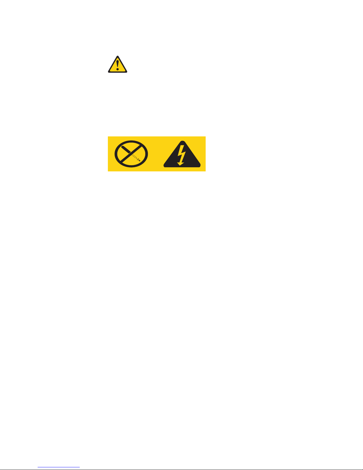
CAUTION:
Never remove the cover on a power supply or any part that has the following
label attached.
Hazardous voltage, current, and energy levels are present inside any
component that has this label attached. There are no serviceable parts inside
these components. If you suspect a problem with one of these parts, contact a
service technician.
Page 15

© Copyright IBM Corp. 2001 1
Chapter 1. Introducing the IBM xSeries 300
You r I BM xSeries 300 is a one U-high1 rack model server for high-volume
network transaction processing. This high-performance server is ideally suited for
networking environments that require superior microprocessor performance, efficient
memory management, flexibility, and reliable data storage.
Your xSeries 300 server comes with a limited warranty and IBM Start Up Support. If
you have access to the World Wide Web, you can obtain up-to-date information about
your xSeries 300 model and other IBM server products at the following World Wide
Web address: http://www.ibm.com/eserver/xseries.
For service, assistance, or additional information on IBM Server Start Up Support and
the World Wide Web, see “Getting help, service, and information” on page 95.
The machine type and serial number are located on the ID label located just behind
the bezel on the right of the server. You will need these numbers when you register
your server with IBM.
1. Racks are marked in vertical increments of 1.75 inches each. Each increment is referred to as a unit, or "U." A one-U-high device is
1.75 inches-tall.
ID label
Page 16

2 xSeries 300: User’s Reference
Features and specifications
The following table provides a summary of the features and specifications for your
xSeries 300.
*KB equals approximately 1000 bytes. MB equals approximately 1000000 bytes. GB
equals approximately 1000000000 bytes.
Microprocessor:
Supports either of the two listed
microprocessors (depending on your
model)
• One Intel Pentium III with 256 KB*
Level-2 cache and MMX (MMX2)
technology
or
• One Intel Celeron with 128 KB
Level-2 cache and MMX (MMX2)
technology
Memory:
• Minimum: 128 MB*
• Maximum: 1.5 GB*
• Type: PC133 MHz, ECC SDRAM,
unregistered DIMMs only
• Slots: Three dual inline
• Supports 128, 256, and 512 MB
DIMMs
Drives:
• Diskette: 1.44 MB
• CD-ROM: 24X IDE
• Supports up to two hard disk
drives
Expansion bays:
Two 3.5-in. slim-high bays for hard
disk drives
PCI expansion slots:
Two 33 MHz/32-bit on the system
board
Power supply:
200 watt (110 or 220 V ac
auto-sensing) with Wake on LAN
support
Video:
• S3 Savage 4 Pro video on
system board
• Compatible with SVGA and VGA
• 8 MB SDRAM video memory
Size:
• Height: 4.37 cm (1.75 inches,
1U)
• Depth: 63.5 cm (25 inches)
• Width: 44 cm (17.32 inches)
• Maximum weight: 12.7 kg (28 lb)
depending on your configuration
Integrated functions:
• Dual 10BASE-T/100BASE-TX
Ethernet controllers on the
system board with Alert on LAN
2 support
• Serial port
• Two USB ports
• Keyboard port
• Mouse port
• Dual-channel bus mastering IDE
controller
Hard disk controller:
• All models-Dual-channel bus
mastering IDE controller
• Some models-SCSI adapter
(Adaptec Ultra160) is installed in
one of the expansion-slots
Acoustical noise emissions:
• Sound power, idling: 6.6 bel
maximum
• Sound power, operating: 6.8 bel
maximum
Environment:
• Air temperature:
— Server on: 10° to 35° C (50.0°
to 95.0° F). Altitude: 0 to 914
m (2998.7 ft)
— Server on: 10° to 32° C (50.0°
to 89.6° F). Altitude: 914 m
(2998.7 ft) to 2133 m (6998.0
ft.)
— Server off: -40° to 60° C
(-104° to 140° F). Maximum
altitude: 2133 m (6998.0 ft)
• Humidity:
— Server on: 8% to 80%
— Server off: 5% to 100%
Heat output:
Approximate heat output in British
thermal unit (Btu) per hour
• Minimum configuration: 171 Btu
(50 watts)
• Maximum configuration: 410 Btu
(120 watts)
Electrical input:
• Sine-wave input (47-63 Hz)
required
• Input voltage low range:
— Minimum: 90 V ac
— Maximum: 137 V ac
• Input voltage high range:
— Minimum: 180 V ac
— Maximum: 265 V ac
• Input kilovolt-amperes (kVA)
approximately:
— Minimum: 0.095 kVA
— Maximum: 0.213 kVA
Page 17

Chapter 1. Introducing the IBM xSeries 300 3
Notices and statements used in this book
The Caution statements and the Danger statements also appear in the multilingual
safety information book provided on the IBM xSeries Documentation CD. Each
statement is numbered for easy reference to the corresponding statement in the
safety book.
The notice and statement definitions are as follows:
• Notes: These notices provide important tips, guidance, or advice.
• Important: These notices provide information or advice that might help you avoid
inconvenient or problem situations.
• Attention: These notices indicate possible damage to programs, devices, or
data. An attention notice is placed just before the instruction or situation in which
damage could occur.
• Caution: These statements indicate situations that can be potentially hazardous
to you. A caution statement is placed just before the description of a potentially
hazardous procedure step or situation.
• Danger: These statements indicate situations that can be potentially lethal or
extremely hazardous to you. A danger statement is placed just before the
description of a potentially lethal or extremely hazardous procedure step or
situation.
Page 18

4 xSeries 300: User’s Reference
What your IBM xSeries 300 offers
The design of your server takes advantage of advancements in memory management
and data storage. Your server includes:
• Impressive performance using the latest microprocessor technology.
Your server comes with one Intel Celeron or one Pentium III microprocessor
installed.
• Large system memory
The memory bus in your server supports up to 1.5 GB of system memory. The
memory controller provides error code correction (ECC) support for up to three
industry-standard PC133, 3.3 V, 168-pin, 133 megahertz (MHz), unregistered,
synchronous dynamic random access memory (SDRAM) dual inline memory
modules (DIMMs).
• Systems-management capabilities
See the documentation provided with your systems-management software for
more information.
• Integrated network environment support
Your server comes with two Intel Ethernet controllers on the system board. These
Ethernet controllers have an interface for connecting to 10-Mbps or 100-Mbps
networks. The server automatically selects between 10BASE-T and 100BASE-TX
environments. The controller provides full-duplex (FDX) capability, which enables
simultaneous transmission and reception of data on the Ethernet local area
network (LAN). These controllers support Alert on LAN 2 technology.
• IBM ServerGuide CDs
The ServerGuide CDs that are included with your server provide programs to help
you set up your server and install the network operating system (NOS). The
ServerGuide program detects the hardware options that are installed and
provides the correct configuration programs and device drivers. In addition, the
ServerGuide CDs include a variety of application programs for your server.
For more information about the ServerGuide CDs, see Chapter 4, “Using the
ServerGuide CDs,” on page 21.
Page 19

Chapter 1. Introducing the IBM xSeries 300 5
Reliability, availability, and serviceability features
Three of the most important features in server design are reliability, availability, and
serviceability (RAS). These RAS features help to ensure the integrity of the data
stored on your server; that your server is available when you want to use it; and that
should a failure occur, you can easily diagnose and repair the failure with minimal
inconvenience.
The following is an abbreviated list of the RAS features that your server supports.
• Reliability features
— Boot block recovery
— Cooling fans with speed-sensing capability
— Customer-upgradable basic input and output system (BIOS) code
— ECC front-side buses (FSBs) and L2 cache
— Advanced configuration and power interface (ACPI)
— Power-on self-test (POST)
— SDRAM with serial presence detect (SPD)
— Parity checking on the SCSI bus
• Availability features
— Advanced desktop management interface (DMI) features
— Auto-restart initial program load (IPL) power supply
— Automatic error retry or recovery
— Automatic server restart
— Automatic restart after power failure
— Built-in, menu-driven configuration programs
— Built-in, menu-driven setup programs
— Failover Ethernet support
— Menu-driven diagnostic programs on CD-ROM
— Microsoft Windows NT failover support
— Monitoring support for temperature, voltage, and fan speed
— Server management
— Wake on LAN capability
• Serviceability features
— 24 hours per day, seven days a week customer support
2
— Adaptec 29160LP built-in self-test (BIST)
— Alert on LAN 2
— CD-ROM-based diagnostics
— Diagnostic support of Ethernet controllers
— Error codes and messages
— Processor serial number access
— Read-only memory (ROM) checksums
— Standard cables present detection
— Standby voltage for system management features and monitoring
— System error logging
— Vital product data (VPD) (includes information stored in nonvolatile memory
for easier remote viewing)
2. Service availability will vary by country. Response time will vary depending on the number and nature of incoming calls.
Page 20

6 xSeries 300: User’s Reference
Server controls and indicators
The following section identifies the controls and indicators on the front and rear of
your server.
Front view
Power-control button: Press this button to manually turn the server on or off.
Power-on light: This green LED lights and stays on when you turn on your server,
and it blinks when the server is in standby mode.
Reset button: Press this button to reset the server and run the power-on self-test
(POST). You might need to use a pen or the end of a straightened paper clip to press
the button.
System-error light: This amber LED lights when a system error occurs.
Diskette drive activity light: When this LED is on, it indicates that the diskette drive
is in use.
Diskette-eject button: Push this button to release a diskette from the drive.
CD eject button: Push this button to release a CD from the drive.
CD drive activity light: When this light is on, it indicates that the CD-ROM drive is in
use.
Power control
button
Power-on
light (green)
Reset
button
System error
light (amber)
Diskette drive
activity light
(green)
Diskette eject
button
CD eject buttonCD activity
light (green)
Page 21

Chapter 1. Introducing the IBM xSeries 300 7
Rear view
System power connector: The system power cord connects here to provide power
to the system.
Ethernet 1 link indicator: This amber LED lights when there is an active link
connection on the 10BASE-T or 100BASE-TX interface for Ethernet port 1.
Ethernet 1 speed indicator: This green LED lights when the speed of the Ethernet
LAN that is connected to Ethernet port 1 is 100 Mbps.
Auxiliary pointing device: Signal cables for a mouse, trackball, or other pointing
device connect to the Auxiliary pointing device connector.
Keyboard port: Signal cables for a keyboard connect to the keyboard port.
Power-on light: This green LED lights and stays on when you turn on your server
and will blink when the server is in standby mode. This light duplicates the power on
light on the front of the server.
Video port: The signal cable for a monitor connects to the video port.
Serial port: Signal cables for modems or other serial devices connect to the serial
port.
USB 2: This is an automatically configured port that you can use to connect one or
more USB devices to the server, using Plug and Play technology.
USB 1: This is an automatically configured port that you can use to connect one or
more USB devices to the server, using Plug and Play technology.
System-error light: This amber LED lights when a system error occurs. This light
duplicates the system error light on the front of the server.
Ethernet 2 speed indicator: This green LED lights when the speed of the Ethernet
LAN connected to Ethernet port 2 is 100 Mbps.
Ethernet 2 link indicator: This amber LED lights when there is an active link
connection on the 10BASE-T or 100BASE-TX interface for Ethernet port 2.
Ethernet 1 speed
indicator (green)
Ethernet 2 speed
indicator (green)
Ethernet 1 link
indicator (amber)
Ethernet 2 link
indicator (amber)
Power-on light (green)
System error
light (amber)
Serial port
USB 1
USB 2
Video port
Mouse or auxilary
pointing device connector
Keyboard port
System power
connector
Page 22

8 xSeries 300: User’s Reference
Turning on the server
Turning on the server refers to the act of plugging the power cord of your server into
the power source and starting the operating system.
Complete the following steps to turn on the server:
1. Plug the power cord of your server into the power source.
Note: Plugging the power cord into a power source may cause the server to start
automatically. This is an acceptable action.
2. Wait 30 seconds, and then press the power control button on the front of the
server.
Turning off the server
Turning off the server refers to the act of disconnecting the server from the power
source.
Complete the following steps to turn off the server:
1. Refer to your operating system documentation for the proper procedure to shut
down the operating system.
Statement 5
CAUTION:
The power control button on the device and the power switch on the power
supply do not turn off the electrical current supplied to the device. The
device also might have more than one power cord. To remove all electrical
current from the device, ensure that all power cords are disconnected from
the power source.
2. Press the power control button on the front of the server. This will put the server
in standby mode.
3. Disconnect the server from the power source.
Note: After you turn off the server, wait at least 5 seconds before you turn on the
server again.
1
2
Page 23

Chapter 1. Introducing the IBM xSeries 300 9
Standby mode
Standby mode puts the server into a wait state. When in a wait state, the server is not
running the operating system, and all core logic is shut down.
Complete the following steps to put the server into the standby mode:
1. Refer to your operating system documentation for the proper procedure to
shutdown the operating system.
2. Press the power control button on the front of the server.
Page 24

10 xSeries 300: User’s Reference
Page 25

© Copyright IBM Corp. 2001 11
Chapter 2. Arranging your workspace
To get the most from your server, arrange both the equipment you use and your work
area to suit your needs and the kind of work you do. Your comfort is of foremost
importance, but light sources, air circulation, and the location of electrical outlets also
can affect the way you arrange your workspace.
Comfort
Although no single working position is ideal for everyone, here are a few guidelines to
help you find a position that suits you best.
Sitting in the same position for a long time can cause fatigue. A good chair can make
a big difference. The backrest and seat should adjust independently and provide good
support. The seat should have a curved front to relieve pressure on the thighs. Adjust
the seat so that your thighs are parallel to the floor and your feet are either flat on the
floor or on a footrest.
When using the keyboard, keep your forearms parallel to the floor and your wrists in a
neutral, comfortable position. Try to keep a light touch on the keyboard and your
hands and fingers relaxed. You can change the angle of the keyboard for maximum
comfort by adjusting the position of the keyboard feet.
Adjust the monitor so the top of the screen is at, or slightly below, eye level. Place the
monitor at a comfortable viewing distance, usually 51 to 61 cm (20 to 24 in.), and
position it so you can view it without having to twist your body. Also position other
equipment you use regularly, such as the telephone or a mouse, within easy reach.
Glare and lighting
Position the monitor to minimize glare and reflections from overhead lights, windows,
and other light sources. Even reflected light from shiny surfaces can cause annoying
reflections on your monitor screen. Place the monitor at right angles to windows and
other light sources, when possible. Reduce overhead lighting, if necessary, by turning
off lights or using lower wattage bulbs. If you install the monitor near a window, use
curtains or blinds to block the sunlight. You might have to adjust the Brightness and
Contrast controls on the monitor as the room lighting changes throughout the day.
Where it is impossible to avoid reflections or to adjust the lighting, an antiglare filter
placed over the screen might be helpful. However, these filters might affect the clarity
of the image on the screen; try them only after you have tried all other methods of
reducing glare.
Dust buildup compounds problems that are associated with glare. Remember to clean
your monitor screen periodically using a soft cloth that is moistened with a
nonabrasive liquid glass cleaner.
Page 26

12 xSeries 300: User’s Reference
Air circulation
Your server and monitor produce heat. Your server has one or more fans that pull in
fresh air and force out hot air. The monitor lets hot air escape through vents. Blocking
the air vents can cause overheating, which might result in a malfunction or damage.
Place the server and monitor so that nothing blocks the air vents; usually, 15 cm (6
inches) of air space is sufficient. Also, make sure that the vented air is not blowing on
someone else.
Electrical outlets and cable lengths
The location of electrical outlets and the length of power cords and cables that
connect to the monitor, printer, and other devices might determine the final placement
of your server.
When arranging your workspace:
• Avoid the use of extension cords. When possible, plug the server power cords
directly into electrical outlets.
• Keep power cords and cables neatly routed away from walkways and other areas
where they might get kicked accidentally.
For more information about power cords, refer to the power cord information in this online publication.
Page 27

© Copyright IBM Corp. 2001 13
Chapter 3. Configuring your server
The following configuration programs are provided with your server:
• Configuration/Setup Utility
This program is part of the basic input/output system (BIOS) code that comes with
your server. You can use this program to configure the serial connector
assignment, change the drive startup sequence, set the date and time, and set
passwords. See “Using the Configuration/Setup Utility program” for more
information.
• SCSISelect Utility
With the SCSISelect Utility program, you can configure the devices that are
attached to the SCSI adapter (provided in some models). Use this program to
change default values, resolve configuration conflicts, and perform a low-level
format on a SCSI hard disk drive. See “Using the SCSISelect utility program
(some models)” on page 16 for more information.
• PXE Boot Agent Utility
The Preboot eXecution Environment (PXE) Boot Agent Utility program is part of
the BIOS code that comes with your server. You can use this program to change
network startup (boot) protocols and startup order, to select operating-system
wake-up support, and to set menu wait times.
• ServerGuide CDs
The ServerGuide CDs include software setup and installation tools that are
specifically designed for IBM xSeries 300 servers. You can use these CDs during
the initial installation of your server to configure the server hardware and to
simplify your NOS installation. The ServerGuide CDs also contain a collection of
application programs, which you can install after your server is up and running.
See Chapter 4, “Using the ServerGuide CDs,” on page 21 for more detailed
information.
Using the Configuration/Setup Utility program
Configuration/Setup is a menu-driven utility that is part of the BIOS code that comes
with your server. You can use it to:
• Configure serial connector assignments
• Change the drive startup sequence
• Enable USB keyboard and mouse support
• Resolve configuration conflicts
• Set the date and time
• Set passwords
The following sections provide instructions for starting the Configuration/Setup Utility
program and descriptions of the menu choices that are available.
Starting the Configuration/Setup Utility program
Complete the following steps to start the Configuration/Setup Utility program:
1. Turn on the server and watch the monitor screen.
2. When the message Press F1 for Configuration/Setup appears, press F1.
3. Follow the instructions that appear on the screen.
Page 28

14 xSeries 300: User’s Reference
Choices available from the Configuration/Setup main menu
From the Configuration/Setup Utility main menu, you can select settings that you want
to change. The Configuration/Setup Utility main menu is similar to the following
illustration:
Notes:
1. You can press F1 to display help information for a selected menu item.
2. The choices on some menus might differ slightly from the ones that are described
in this book, depending on the version of BIOS code in your server.
Descriptions of the choices that are available from the main menu are as follows:
• System Summary
Select this choice to display configuration information. This includes the type and
speed of the microprocessor and the amount of memory that is installed.
Changes that you make to configuration settings appear on this summary screen.
You cannot edit the fields.
This choice appears on both the full and limited Configuration/Setup Utility
menus.
• Product Data
Select this choice to view system information, such as the machine type and
model, the server serial number, and the revision level or issue date of the BIOS
code that is stored in the flash electrically erasable programmable read-only
memory (EEPROM).
• Devices and I/O Ports
Select this choice to view or change the assignments for devices and input/output
ports. This choice appears only on the full Configuration/Setup Utility main menu.
• Start Options
Select this choice to view or change the start options. Start options take effect
when you start your server.
You can select keyboard operating characteristics, such as the keyboard speed.
You also can specify whether the server starts with the keyboard number lock on
or off.
CMOS Setup Utility - Copyright (c) 1984 - 2000 Award Software
Move Enter: Select F1: General Help
F10: Save ESC: Exit
System Summary
Product Data
Devices and I/O Ports
Date and Time
System Security
Advanced Setup
Power Management Setup
Start Options
Frequency Control
Save & Exit Setup
Load Optimized Defaults
Exit Without Saving
Configuration/Setup Utility
Select Option:
Page 29

Chapter 3. Configuring your server 15
The server uses a startup sequence to determine the device from which the
operating system starts. For example, you can define a startup sequence that
checks for a startable diskette in the diskette drive, then checks the hard disk
drive in bay 5, and then checks a network adapter.
You can enable a virus-warning test that checks for changes in the master boot
record at startup. You also can choose to run POST in the quick mode, and read
the microprocessor serial number.
• Frequency Control
Select this choice to enable or disable the auto-detect DIMM/PCI clock.
• Date and Time
Select this choice to set the system date and time.
The system time is in a 24-hour format: hour:minute:second.
Note: You may also set the date and time using the procedures provided on the
ServerGuide CDs.
• System Security
Select this choice to set a power-on or an administrator password. See “Using
passwords” on page 16 for more information.
• Advanced Setup
Select this choice to change values for advanced hardware features, such as
Cache Control and PCI configuration.
A message appears above the choices on this menu to alert you that the system
might malfunction if these options are configured incorrectly. Follow the
instructions on the screen carefully.
— Cache Control
Select this choice to enable or disable the microprocessor cache.
Attention: Do not make changes to the Cache Control unless directed to do
so by an IBM authorized service representative.
— ROM Shadowing
Select this choice to enable or disable the state of ROM shadowing.
— Chipset Feature
Select this choice to modify settings that control features of the core chip set
on the system board.
Attention: Do not make changes to the Chipset Feature unless directed to
do so by IBM.
— Memory Settings
Select this choice to manually enable or disable a bank of memory.
If a memory error is detected during POST or memory configuration, the
server can automatically disable the failing memory bank and continue
operating with reduced memory capacity. If this occurs, you must manually
enable the memory bank after the problem is corrected. Select Memory
Settings from the Advanced Setup menu, use the arrow keys to highlight the
bank that you want to enable; then, use the arrow keys to select Enable.
• Power Management Setup
Select this choice to enable or disable system power savings.
• Save & Exit Setup
Select this choice to save your customized settings.
• Load Optimized Defaults
Page 30

16 xSeries 300: User’s Reference
Select this choice to discard your changes and restore the factory settings.
• Exit Without Saving
Select this choice if you want to exit without saving changes, or if no changes
have been made.
Using passwords
The System Security choice appears only on the full Configuration/Setup Utility
menu. After you select this choice, you can set a power-on password or an
administrator password.
You can use any combination of up to seven characters (A–Z, a–z, and 0–9) for the
power-on password or the administrator password. When you have set one or both of
the passwords, record them and keep them in a secure place.
If both a power-on and administrator password are set, you can type either password
at the password prompt that appears as you start your server. However, if you want to
change the settings in the Configuration/Setup Utility program, you must type the
administrator password to access the full configuration menus. If you type the poweron password, you can only view limited information in the Configuration/Setup Utility
program.
If you forget the power-on password, you can regain access to the server through
either of the following methods:
• Start the Configuration/Setup Utility program and change the power-on password.
• Change the jumper position on the CMOS jumper as described in “Clearing
CMOS” on page 81.
Using the SCSISelect utility program (some models)
SCSISelect is a built-in, menu-driven configuration utility program that you can use to:
• View the default SCSI IDs
• Locate and correct configuration conflicts
The following sections provide instructions for starting the SCSISelect Utility program
and descriptions of the menu choices that are available.
Note: If your server has a redundant arrays of independent disks (RAID) adapter
installed, use the configuration method that is supplied with the RAID adapter
to view or change SCSI settings for devices attached to the adapter.
Starting the SCSISelect utility program
Complete the following steps to start the SCSISelect Utility program:
1. Turn on the server.
2. When the <<< Press <CTRL><A> for SCSISelect
TM
Utility! >>> prompt
appears, press Ctrl+A.
3. When the Would you like to configure the host adapter or run the SCSI
disk utility? question appears, make your selection and press Enter.
4. Use the arrow keys to select a choice from the menu.
• Press Esc to exit the SCSISelect Utility program.
• Press the F5 key to switch between color and monochrome modes (if your
monitor permits).
Page 31

Chapter 3. Configuring your server 17
5. Follow the instructions on the screen to change the settings of the selected items;
then, press Enter.
Choices available from the SCSISelect menu
The following choices appear on the SCSISelect Utility menu:
• Configure/View Host Adapter Settings
Select this choice to view or change the SCSI controller settings. To reset the
SCSI controller to its default values, press F6; then, follow the on-screen
instructions.
You can view or change the following controller settings:
— Host Adapter SCSI ID
Select this choice to view the SCSI controller identification (ID), which is
usually 7.
— SCSI Parity Checking
Select this choice to view the assigned value of Enabled.
— Host Adapter SCSI Termination
Select this choice to view the assigned value of Automatic.
— Boot Device Options
Select this choice to configure startable-device parameters. Before you can
make updates, you must know the ID of the device whose parameters you
want to configure.
— SCSI Device Configuration
Select this choice to configure SCSI-device parameters. Before you can make
updates, you must know the ID of the device whose parameters you want to
configure.
Note: The Maximum Sync Transfer Rate is the transfer rate for Ultra SCSI
devices.
– The transfer rate for Ultra160 low voltage differential (LVD) devices
is 160.0 MBps.
– The transfer rate for Ultra2 SCSI LVD devices is 80.0 MBps.
– The transfer rate for Fast SCSI devices is 20.0 MBps.
— Advanced Configuration Options
Select this choice to view or change the settings for advanced configuration
options. These options include support for large hard disk drives and support
for drives with Ultra SCSI speeds.
• SCSI Disk Utilities
Select this choice to view the SCSI IDs that are assigned to each device or to
format a SCSI device.
To use the utility program, select a drive from the list. Read the on-screen
instructions carefully before making a selection.
Note: If you press Ctrl+A before the selected drives are ready, an Unexpected
SCSI Command Failure screen might appear. Restart the server and
watch the SCSISelect messages as each drive starts. After the drive that
you want to view or format starts, press Ctrl+A.
Page 32

18 xSeries 300: User’s Reference
Using the PXE boot agent utility program
The PXE boot agent is a built-in, menu-driven configuration utility program that you
can use to:
• Change network startup (boot) protocols
• Change startup (boot) order
• Select whether or not to display setup prompt
• Set menu wait time
• Select OS wake up support
The following sections provide instructions for starting the PXE Boot Agent Utility
program and descriptions of the menu choices that are available.
Starting the PXE boot agent utility program
To start the PXE Boot Agent Utility program:
1. Turn on the server.
2. When the Initializing Intel (R) Boot Agent Version X.X.XX
PXE 2.0 Build XXX (WfM 2.0) prompt appears, press Ctrl+S.
Note: By default you will have two seconds after the prompt appears on the
screen to press Ctrl+S.
3. Use the arrow keys or press Enter to select a choice from the menu.
• Press Esc to return to the previous menu.
• Press the F4 key to exit.
4. Follow the instructions on the screen to change the settings of the selected items;
then, press Enter.
Choices available from the PXE boot agent utility
The following choices appear on the PXE boot agent utility menu:
• Network Boot Protocol
PXE is the default value for this menu item.
Note: Do not change this value. There are no other network boot protocols
supported.
• Boot Order
Select this choice to change the order in which boot devices are queried.
— Try local drives first, then network (Default)
— Try network only
— Try local drives only
— Try network first, then local drives
Note: This option is not supported on this product. To change the boot order use
the Configuration/Setup utility. See “Using the Configuration/Setup Utility
program” on page 13 for more information.
• Show setup prompt
Select this choice to either display the PXE setup prompt or disable it. Disable is
the default setting.
When this choice is enabled, Press Ctrl+S to enter the setup menu will appear
on the screen under the initializing prompt.
Page 33

Chapter 3. Configuring your server 19
• Setup time wait menu
Select this choice to set the amount of time (in seconds) that the system will
pause during initialization for a Ctrl+S input.
— 2 seconds (Default)
— 3 seconds
— 5 seconds
— 8 seconds
• Legacy OS wake up support
Select this choice to enable or disable the operating system wake up support.
— Disabled (Default)
— Enabled
Notes:
1. Use the default setting for Advanced Configuration and Power Interface (ACPI)
aware operating systems, such as Windows 2000 and Windows NT.
2. If your server is running a non-ACPI operating system, you must set this selection
to enable to use the Wake-on-LAN support.
3. When using a non-ACPI operating system, do not send a wake up packet to the
server while it is turned on. If a wake up packet has been sent while the server is
on, and you are unable to turn the server off, see the "Power" section in the
Troubleshooting charts, on page 84 for more information.
Page 34

20 xSeries 300: User’s Reference
Page 35

© Copyright IBM Corp. 2001 21
Chapter 4. Using the ServerGuide CDs
The ServerGuide CDs include easy-to-use software setup and installation tools that
are specifically designed for your IBM server. The ServerGuide Setup and Installation
program detects the server model and hardware options that are installed and uses
that information during setup to configure the hardware. The ServerGuide tools
simplify NOS installations by providing updated device drivers, and in some cases,
installing them automatically.
If a newer version of the ServerGuide software is available, you can purchase an
update package. For details, see the ServerGuide Updates form that comes with your
server library, or go to the ServerGuide fulfillment Web site at
http://www.ibm.com/pc/coupon
The ServerGuide software has these features to make setup easier:
• An easy-to-use interface with online help
• Diskette-free setup and configuration programs that are based on detected
hardware
• Performance Optimizer program, which easily tunes your server for your
environment
• A system BIOS update program, which updates the BIOS directly from the CD
• Device drivers that are provided for your server model and detected hardware
• NOS partition size and file-system type that are selectable during setup
• Powerful application programs and administration tools
Page 36

22 xSeries 300: User’s Reference
Features at a glance
The following is a summary of ServerGuide features.
Note: Exact features and functions can vary with different versions of the
ServerGuide software. To learn more about the version that you have, start the
Setup and Installation CD and view the Online Overview.
Setup and Installation CD
Note: The ServerGuide program
requires a supported IBM
server with an enabled
startable (bootable) CD-ROM
drive. Not all features are
supported on all models.
• Sets system date and time.
• Detects the ServeRAID adapter
or controller and runs the
ServeRAID configuration
program.
• Updates the licensed internal
code (firmware) level without
creating diskettes.
• Checks the system BIOS and
microcode (firmware) levels of
supported options to determine
whether a later level is available
from the CD. You can perform
updates without the use of
diskettes.
• Provides the Performance
Optimizer program to easily tune
your server for your environment.
• Creates a System Partition on the
default drive. You can run serverspecific utility programs after
setup.
• Detects installed hardware
options and provides updated
device drivers for most adapters
and devices.
Setup and Installation CD
(continued)
• Creates a Setup Replication
Diskette for replicating setup
selections for other servers of the
same model.
• Provides diskette-free installation
for Microsoft Windows 2000,
Windows NT, and NetWare
operating systems.
• Provides a replicated installation
path for multiple Windows 2000,
Windows NT Server 4.0, and
Windows Enterprise Edition, and
Red Hat Linux.
• Includes an online README file
with links to tips for your hardware and NOS installation.
Note: Installation requires your NOS
CD.
System Updates and Applications
CD
• Creates diagnostic, RAID, device
driver, and other support
diskettes from the CD; or with an
Internet connection, you can
check for an update from a
dedicated IBM file transfer
protocol (FTP) server.
• Installs some updates without
requiring diskettes. Where
applicable, you can run
executable files directly from the
CD or unzip files to any drive on
your server or another server on
your network.
System Updates and Applications
CD (continued)
• Includes a vast library of fully
tested device drivers for your
server.
• Includes a search function to help
you locate updates by title or
keywords.
• Installs powerful applications
directly from the CD. See the CD
label for a current list of
applications.
Page 37

Chapter 4. Using the ServerGuide CDs 23
Setup and configuration overview
When you use the Setup and Installation CD, you do not need setup diskettes. You
can use the CD to configure any supported IBM server model. The setup program
checks your system BIOS, service processors, and other system hardware to
determine if system updates are available. The setup program provides a list of tasks
that are required to set up your server model. On RAID servers, you can run the
ServeRAID Manager program to create logical drives.
Note: Exact features and functions can vary with different versions of the
ServerGuide software.
When you start the Setup and Installation CD, the following happens:
• You are prompted for your language, country, and keyboard layout. (This
information is stored and later passed on to the NOS installation program.)
• ServerGuide displays choices for running the configuration programs. For
example:
— The Express Configuration method runs the required programs for your
server, based on the hardware that is detected.
— The Custom Configuration method displays all programs that are available for
your server, and you decide which programs to run.
— The Replicated Configuration method provides the option of duplicating your
setup selections to other servers that are the same model.
• If you select the Custom Configuration method, the following programs are
optional. If you select the Express Configuration method, some or all of these
programs are run, depending on the hardware that is detected.
— The Set Date and Time feature is provided so that you do not have to use the
Configuration/Setup Utility program to access these settings.
— The Clear Hard Disks program is provided so you can delete all partitions on
all hard disk drives. If the server has a ServeRAID adapter installed, you can
select to restore the configuration on the ServeRAID adapter to the factory
default settings.
— ServerGuide checks the server BIOS and microcode (firmware) levels for
supported options and then checks the CD for a newer level. CD content can
be newer than the hardware. ServerGuide can perform a flash update of the
BIOS and supported microcode (firmware) options without the use of
diskettes.
— The ServeRAID configuration program starts, leading you through the entire
configuration process.
— The Performance Optimizer program easily tunes your server for your
environment.
— ServerGuide creates a System Partition on the default drive.
• ServerGuide displays a confirmation summary, so that you will know when you
have completed all the required tasks. Then, you are ready to install your NOS.
Notes:
1. Plug and Play adapters are configured automatically. Non-Plug and Play adapters
or non-IBM adapters might require switch settings, additional device drivers, and
installation after the NOS is installed. See the documentation that comes with the
adapter.
2. Diagnostics for your server come in BIOS or on a separate diagnostics CD.
Page 38

24 xSeries 300: User’s Reference
System Partition
ServerGuide creates a 50 MB System Partition on the default drive. The System
Partition contains server-specific utility programs such as service processor disk
operating system (DOS) utilities, system diagnostics, flash BIOS updates, and other
programs.
Note: Programs in the System Partition vary by server model, and not all server
models run utility programs from the System Partition. To determine which
ones do, start the Setup and Installation CD and view the online Overview.
After setup is complete, you can access programs in the System Partition by
restarting the server and pressing Alt+F1 when the prompt is displayed. The System
Partition menu displays the programs that are available on your server model.
Typical NOS installation
You can use ServerGuide to shorten your installation time. ServerGuide provides the
necessary device drivers, based on the hardware that you have and the NOS that you
are installing. The following is a brief explanation of a typical ServerGuide NOS
installation.
Note: Exact features and functions can vary with different versions of the
ServerGuide software
• After you have completed the setup process, the operating system installation
program starts. (You will need your copy of the NOS CD to complete the
installation.)
• ServerGuide stores information about the server model, service processor, hard
disk controllers, and network adapters. It then checks the CD for newer device
drivers. This information is stored and then passed to the NOS installation
program.
• With some NOS installations, you can create a NOS Replication Diskette for
setting up additional servers. The diskette will contain the Internet protocol (IP)
address, server name, and other selections.
• ServerGuide presents NOS partition options that are based on your NOS
selection and the installed hard disk drives.
• If you are installing the NOS from diskette, ServerGuide displays the required
diskettes that you must create, and the optional diskettes that you might want to
create. The diskettes that you can create are the device driver diskettes for the
installed adapters or controllers.
ServerGuide prompts you to insert your NOS CD and restart the server. At this point,
the installation program for the NOS (for example, Microsoft Windows 2000) takes
control to complete the installation.
Setting up or updating multiple servers
You can use ServerGuide to create diskettes that help you set up or update multiple
servers. You can modify information on the diskettes as you use them to set up or
update other servers.
Note: Availability and function can vary by server model and by the hardware that is
installed.
Page 39

Chapter 4. Using the ServerGuide CDs 25
You can create a Setup Replication Diskette, which contains your hardware
configuration selections. Use this diskette to replicate selections to other servers that
are of the same model.
You can create a NOS Replication Diskette, which contains your server name, domain
name, and other information that you need to complete multiple installations. This
feature supports systems running Windows 2000, Windows NT Server 4.0, and Red
Hat Linux.
Installing your NOS without ServerGuide
If you have already configured the server hardware and you decide not to use
ServerGuide to install your NOS, download the latest NOS installation instructions:
1. Go to http://www.ibm.com/pc/support
2. Click Servers.
3. From the Family field, select your server model.
4. Click OS installation. The available installation instructions are listed.
Additional programs included with ServerGuide
As a convenience, ServerGuide comes with additional software to assist you with the
server installation.
A variety of powerful applications are included with ServerGuide. Offerings can vary
with the different versions of the ServerGuide software. Check the application CD
labels for a list of applications, or start the Setup and Installation CD and view the
online Overview.
Error symptoms
This section provides ServerGuide error symptoms and probable solutions.
Setup and
Installation CD
Action
Setup and
Installation CD will
not start.
• Ensure that the system is a supported server model with a startable
(bootable) CD-ROM drive.
• If the startup (boot) sequence settings have been altered, be sure
that the CD-ROM is first in the startup sequence.
• If more than one CD-ROM drive is installed, be sure that only one
drive is set as the primary drive. Start the CD from the primary
drive.
ServeRAID
program cannot
view all installed
drives or cannot
install NOS.
• Ensure that there are no duplicate SCSI IDs or IRQ assignments.
• Ensure that the hard disk drive is connected properly.
The operating
system installation
program
continuously loops.
Free up more space on the hard disk.
Page 40

26 xSeries 300: User’s Reference
ServerGuide will
not start your NOS
CD.
Ensure that the NOS CD is supported by ServerGuide. See the Setup
and Installation CD label for a list of supported NOS versions.
Cannot install
NOS.
Ensure that the NOS is supported on your server. If the NOS is
supported, either there is no logical drive defined (ServeRAID systems)
or the ServerGuide System Partition is not present. Run the
ServerGuide setup and configuration program and ensure that the setup
is complete.
System Updates
and Applications
CD
Action
Get "time out" or
"Unknown host"
errors.
Ensure that you have access to the Internet through FTP directly.
Setup and
Installation CD
Action
Page 41
© Copyright IBM Corp. 2001 27
Chapter 5. Installing options
This chapter provides instructions to help you install options in your server. Some
option-removal instructions are provided, in case you need to remove one option to
install another. For a list of supported options for your server, see the ServerProven
list at http://www.ibm.com/pc/compat.
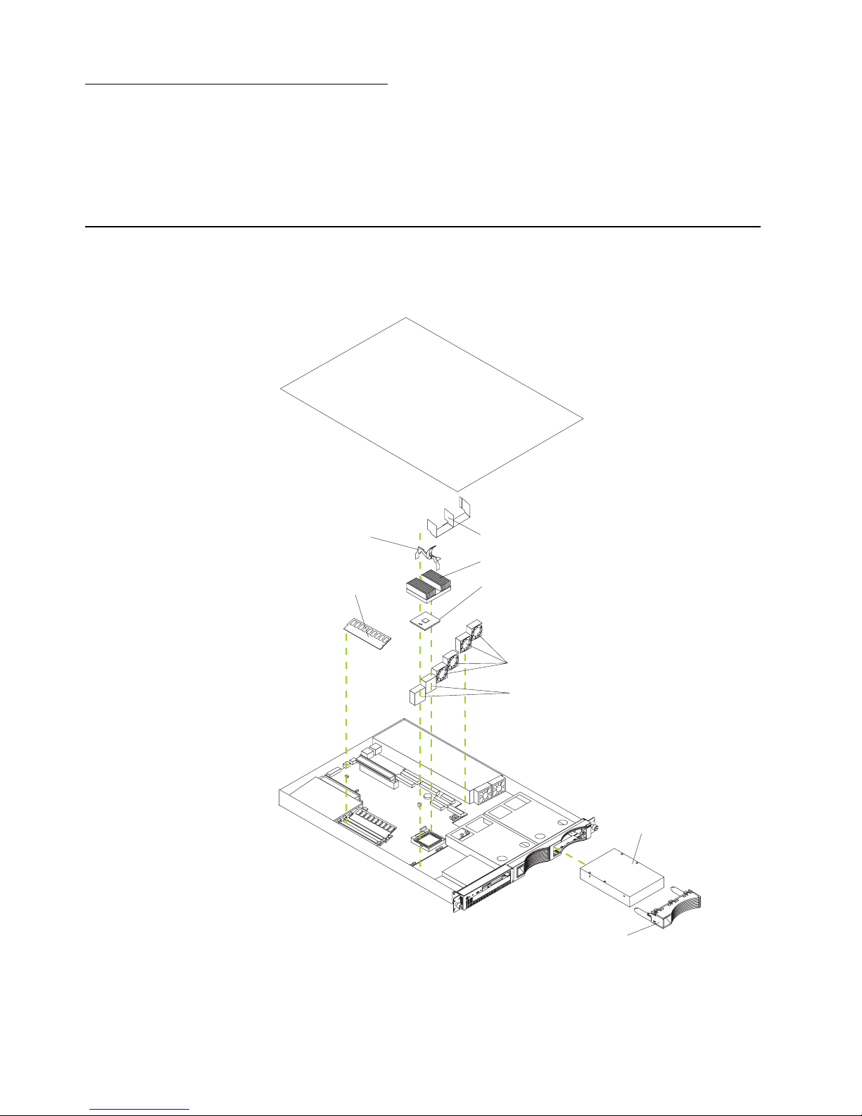
Major components of the xSeries 300
The following illustration shows the locations of major components in your server.
Note: The illustrations in this document might differ slightly from your hardware.
Microprocessor
Fans
Hard disk drive
filler panel
Hard disk drive
Memory module
Air baffle
Heat sink
Clip
Blanks
Page 42

28 xSeries 300: User’s Reference
System board internal cable connectors
The following illustration identifies the internal connectors on the system board.
Microprocessor
(U21)
DIMM 1
DIMM 2
DIMM 3
Battery
PCI slot 1
(PCI 1)
PCI slot 2
(PCI 2)
CPU fan A
(CPUFAA)
CPU fan B
(CPUFAB)
Front panel
(FPI)
System fan 2
(SYSFAN2)
System fan 1
(SYSFAN1)
Secondary IDE
(IDE2)
Primary IDE
(IDE1)
Page 43

Chapter 5. Installing options 29
System board jumpers
The following illustration identifies the jumpers on the system board.
Before you begin
Before you begin to install options in your server, read the following information:
• Become familiar with the information in “Handling static-sensitive devices” on
page 30 and the safety guidelines provided in the “Safety Information” on page
31. These guidelines will help you work safely while working with your server or
options.
• Make sure that you have an adequate number of properly grounded electrical
outlets for your server, monitor, and any other options that you intend to install.
• Back up all-important data before you make changes to disk drives.
• For a list of supported options for the xSeries 300, refer to
http://www.ibm.com/pc/us/compat on the World Wide Web.
Page 44

30 xSeries 300: User’s Reference
System reliability considerations
To help ensure proper cooling and system reliability, make sure that:
• Each of the drive bays has an electromagnetic compatibility (EMC) shield and
either a drive or a filler panel installed.
• There is space around the server to allow the cooling system to work properly.
• Cables for optional adapters are routed according to the instructions that are
provided with the adapters.
• A failed fan is replaced within 48 hour.
Handling static-sensitive devices
Attention: Static electricity can damage electronic devices and your system. To avoid
damage, keep static-sensitive devices in their static-protective package until you are
ready to install them.
To reduce the possibility of electrostatic discharge, observe the following precautions:
• Limit your movement. Movement can cause static electricity to build up around
you.
• Handle the device carefully, holding it by its edges or its frame.
• Do not touch solder joints, pins, or exposed printed circuitry.
• Do not leave the device where others can handle and possibly damage the
device.
• While the device is still in its anti-static package, touch it to an unpainted metal
part of the system unit for at least two seconds. (This drains static electricity from
the package and from your body.)
• Remove the device from its package and install it directly into your system unit
without setting it down. If it is necessary to set the device down, place it in its
static-protective package. Do not place the device on your system unit cover or on
a metal table.
• Take additional care when handling devices during cold weather because heating
reduces indoor humidity and increases static electricity.
Page 45

Chapter 5. Installing options 31
Safety Information
Before installing this product, read the Safety Information.
Antes de instalar este produto, leia as Informações de Segurança.
Læs sikkerhedsforskrifterne, før du installerer dette produkt.
Lees voordat u dit product installeert eerst de veiligheidsvoorschriften.
Ennen kuin asennat tämän tuotteen, lue turvaohjeet kohdasta Safety Information.
Avant d'installer ce produit, lisez les consignes de sécurité.
Vor der Installation dieses Produkts die Sicherheitshinweise lesen.
Prima di installare questo prodotto, leggere le Informazioni sulla Sicurezza
Les sikkerhetsinformasjonen (Safety Information) før du installerer dette produktet.
Pred instalací tohoto produktu si prectete prírucku bezpecnostních instrukcí.
Page 46

32 xSeries 300: User’s Reference
Antes de instalar este produto, leia as Informações sobre Segurança.
Antes de instalar este producto lea la información de seguridad.
Läs säkerhetsinformationen innan du installerar den här produkten.
Page 47

Chapter 5. Installing options 33
Statement 1
DANGER
To Connect: To Disconnect:
1. Turn everything OFF.
2. First, attach all cables to devices.
3. Attach signal cables to connectors.
4. Attach power cords to outlet.
5. Turn device ON.
1. Turn everything OFF.
2. First, remove power cords from outlet.
3. Remove signal cables from connectors.
4. Remove all cables from devices.
Electrical current from power, telephone, and communication cables is
hazardous.
To avoid a shock hazard:
• Do not connect or disconnect any cables or perform installation,
maintenance, or reconfiguration of this product during an electrical
storm.
• Connect all power cords to a properly wired and grounded electrical
outlet.
• Connect to properly wired outlets any equipment that will be attached
to this product.
• When possible, use one hand only to connect or disconnect signal
cables.
• Never turn on any equipment when there is evidence of fire, water, or
structural damage.
• Disconnect the attached power cords, telecommunications systems,
networks, and modems before you open the device covers, unless
instructed otherwise in the installation and configuration procedures.
• Connect and disconnect cables as described in the following table
Page 48

34 xSeries 300: User’s Reference
Statement 2
CAUTION:
When replacing the lithium battery, use only IBM Part Number 33F8354 or an
equivalent type battery recommended by the manufacturer. If your system has
a module containing a lithium battery, replace it only with the same module
type made by the same manufacturer. The battery contains lithium and can
explode if not properly used, handled, or disposed of.
Do not:
• Throw or immerse into water.
• Heat to more than 100 C (212 F)
• Repair or disassemble
Dispose of the battery as required by local ordinances or regulations.
Statement 3
CAUTION:
When laser products (such as CD-ROMs, DVD drives, fiber optic devices, or
transmitters) are installed, note the following:
• Do not remove the covers. Removing the covers of the laser product could
result in exposure to hazardous laser radiation. There are no serviceable
parts inside the device.
• Use of controls or adjustments or performance of procedures other than
those specified herein might result in hazardous radiation exposure.
Danger
Some laser products contain an embedded Class 3A or Class 3B laser diode. Note
the following. Laser radiation when open. Do not stare into the beam, do not view
directly with optical instruments, and avoid direct exposure to the beam.
Page 49

Chapter 5. Installing options 35
Statement 4
≥18 kg (39.7 lbs) ≥32 kg (70.5 lbs) ≥55 kg (121.2 lbs)
CAUTION:
Use safe practices when lifting.
Statement 5
CAUTION:
The power control button on the device and the power switch on the power
supply do not turn off the electrical current supplied to the device. The device
also might have more than one power cord. To remove all electrical current
from the device, ensure that all power cords are disconnected from the power
source.
1
2
Page 50

36 xSeries 300: User’s Reference
Statement 8
CAUTION:
Never remove the cover on a power supply or any part that has the following
label attached.
Hazardous voltage, current, and energy levels are present inside any
component that has this label attached. There are no serviceable parts inside
these components. If you suspect a problem with one of these parts, contact a
service technician.
Page 51

Chapter 5. Installing options 37
Removing the cover
Complete the following steps to remove the server cover:
1. Review the information in “Before you begin” on page 29.
2. Turn off the server and all attached devices and disconnect all external cables and
power cords.
3. Remove the server from the rack.
4. Remove the two screws from the rear of the server.
5. Pull out the cover-release lever at the back of the server to release the cover.
6. Slide the cover back, then up and off the server.
Attention: For proper cooling and airflow, replace the cover before turning on the
server. Operating the server for extended periods of time (over 30 minutes) with
the cover removed might damage server components.
Cover release
lever
Screws
Page 52

38 xSeries 300: User’s Reference
Working with adapters
This section provides information about the expansion slots on the system board, and
peripheral component interconnect (PCI) adapters. Some models come with an
Adaptec SCSI adapter installed in one of the PCI slots.
Attention: Your server comes with an integrated video controller on the system
board. When you install a video adapter in a PCI slot, the server BIOS automatically
disables the integrated video controller. This enables the video adapter in the PCI slot
to control the video functions for your monitor.
The following illustration shows the location of the 33 MHz PCI expansion slots on the
system board.
Note: The illustrations in this document might differ slightly from your hardware.
PCI slot 1
(PCI 1)
PCI slot 2
(PCI 2)
Page 53
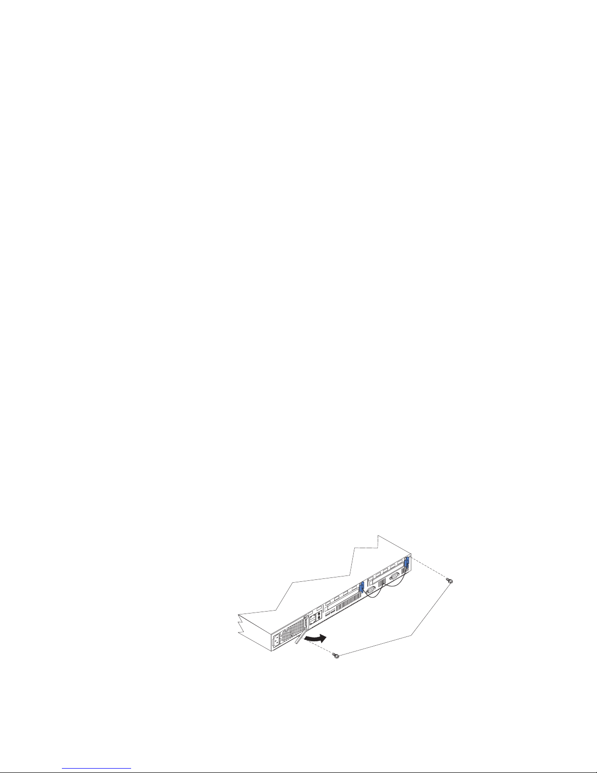
Chapter 5. Installing options 39
Adapter considerations
Before you install adapters, review the following:
• Locate the documentation that comes with the adapter and follow those
instructions in addition to the instructions in this chapter.
• If you need to change the switch settings or jumper settings on your adapter,
follow the instructions that come with the adapter.
• You can install 32-bit full-length or half-length adapters in the expansion slots.
Full-length adapters are installed in slot 1 only; half-length adapters are installed
in either slot 1 or 2.
• Your server supports 5.0 V and universal PCI adapters; it does not support 3.3 V
only adapters.
• Your server uses a rotational interrupt technique to configure PCI adapters. You
can use this technique to install PCI adapters that currently do not support
sharing of PCI interrupts.
• The system scans PCI slots to assign system resources. By default the system
starts (boots) the CD-ROM and diskette drives first. Then it starts PCI slot 2, PCI
slot 1, and the integrated Ethernet.
Note: You can use the Configuration/Setup Utility program to change the boot
precedence for your server. Select Start Options from the
Configuration/Setup Utility program main menu.
Installing an adapter
Complete the following steps to install an adapter:
Attention: When you handle static-sensitive devices, take precautions to avoid
damage from static electricity. For details on handling these devices, see “Handling
static-sensitive devices” on page 30.
1. Review the information in “Before you begin” on page 29.
2. Turn off the server and peripheral devices.
3. Remove all external cables from the server; then, remove the server from the
rack, and remove the cover.
Cover release
lever
Screws
Page 54

40 xSeries 300: User’s Reference
4. Remove the expansion-slot clip that holds the expansion-slot cover in place by
sliding it upward and off the frame of the server.
Note: The illustrations in this document might differ slightly from your hardware.
5. Remove the expansion-slot cover.
6. Refer to the documentation that comes with your adapter for any cabling
instructions.
Attention: You should route adapter cables before you install the adapter.
7. Set any jumpers or switches as described by the adapter manufacturer.
8. Install the adapter:
Note: When installing an adapter into slot 2, skip steps a and d.
a. Open the adapter-retention latch by pushing the blue tab to release it. Then,
push the latch up to the full open position.
b. Carefully grasp the adapter by its top edge or upper corners, and align it with
the connector on the PCI riser card.
c. Press the adapter firmly into the riser card connector.
Attention: When you install an adapter, be sure the adapter is correctly
seated in the riser-card connector before you turn on the server. Improperly
seated adapters might cause damage to the system board, the riser card, or
the adapter.
d. Push down on the blue adapter retention latch until it clicks into place,
securing the adapter.
e. Replace the expansion-slot clip by sliding it down until it latches into place
and holds the adapter securely.
Retention
latch
Ta b
Adapter
Expansion-slot
clip
Expansionslot cover
Expansion
slot
Page 55

Chapter 5. Installing options 41
9. Connect the internal cables to the adapter.
Attention: Route cables so that they do not block the flow of air from the fans.
10. If you have other options to install or remove, do so now.
11. Replace the cover on the server; then, reinstall the server in the rack and connect
all external cables. For more information, see “Installing the cover” on page 46 for
instructions.
12. Turn on the server.
Page 56

42 xSeries 300: User’s Reference
Hard disk drives
Your server supports two, 1-inch (26 mm) slim 3.5-inch hard disk drives.
Depending on the model, your server supports two SCSI or two IDE hard disk drives.
Installing or replacing a hard disk drive
Complete the following steps to install or replace a hard disk drive:
Attention: When you handle static-sensitive devices, take precautions to avoid
damage from static electricity. For details on handling these devices, see “Handling
static-sensitive devices” on page 30.
1. Inspect the drive for any signs of damage.
2. Review the information in “Before you begin” on page 29, and “Safety Information”
on page 31.
3. Check the instructions that come with the drive for more information about
installing your drive.
Notes:
a. If you are installing an IDE hard disk drive, you must set the drive to primary
(master) or secondary (subordinate), depending on the configuration of your
server. See the documentation that comes with the drive for instructions.
b. If you are installing a SCSI hard disk drive, refer to the documentation that
comes with your drive before installing it.
4. Turn off the server and peripheral devices and disconnect all external cables and
power cords.
5. Remove the server from the rack and remove the cover.
Note: If you are replacing a failing hard disk drive, remove the fans behind the
drive bay in which you are working; then, disconnect the power and signal
cables from the hard disk drive.
6. Remove the filler panel or defective hard disk drive from one of the hard disk drive
bays.
7. Install the new hard disk drive in the drive bay:
a. Slide the drive into the bay and align the screw holes in the drive with the
screw holes in the server chassis.
b. Use a screwdriver to secure the hard disk drive to the server chassis.
Filler panel
Hard disk drive
Page 57

Chapter 5. Installing options 43
c. Connect the signal cable and power cable to the rear of the drive. Ensure that
the cables do not obstruct the fan behind the drive bay.
8. If you have other options to install or remove, do so now.
9. Replace the server cover. See “Installing the cover” on page 46.
10. Reconnect the external cables and power cords; then, turn on the server.
Installing DIMMs
Adding memory to your server is an easy way to make programs run faster. You can
increase the amount of memory in your server by installing options that are called
DIMMs. Your server uses a noninterleaved memory configuration.
Memory considerations:
• Your server comes with a DIMM installed on the system board in DIMM connector
1. When installing additional memory modules, install the second memory module
in DIMM connector 2 and the third in DIMM connector 3. (See the figure on page
42 for memory connector locations.)
• Your xSeries 300 server supports 128 MB, 256 MB, and 512 MB DIMMs. Your
server supports a maximum of 1.5 GB of system memory. See the ServerProven
®
list at http://www.ibm.com/pc/compat for a list of memory modules for use with
your server.
• The installing or removing of DIMMs changes the configuration information in the
server. Therefore, you must change and save the new configuration information
by using the Configuration/Setup Utility program. When you restart the server, the
system displays a message indicating that the memory configuration has
changed. Start the Configuration/Setup Utility program and select Save Settings.
See Chapter 3, “Configuring your server,” on page 13 for more information.
• The illustrations in this document might differ slightly from your hardware.
Complete the following steps to install a DIMM:
Attention: When you handle static-sensitive devices, take precautions to avoid
damage from static electricity. For details on handling these devices, see “Handling
static-sensitive devices” on page 30.
1. Review the safety precautions in “Safety Information” on page 31.
2. Turn off the server and peripheral devices, and disconnect all external cables and
power cords. Then, remove the cover (see “Removing the cover” on page 37 for
details).
3. If necessary, remove the adapter in PCI slot 2 for easier access to the memory
connectors.
4. Touch the static-protective package containing the DIMM to any unpainted metal
surface on the server. Then, remove the DIMM from the package.
Page 58

44 xSeries 300: User’s Reference
5. Install the DIMM:
a. Open the retaining clip on each end of the DIMM connector. Turn the DIMM
so that the pins align correctly with the connector.
Attention: To avoid breaking the retaining clips or damaging the DIMM
connectors, open, and close the clips gently.
b. Insert the DIMM into the connector by aligning the DIMM edges with the slots
at each end of the DIMM connector. Firmly press the DIMM straight down into
the connector by applying pressure on both ends of the DIMM simultaneously.
Be sure that the retaining clips snap into the locked position when the DIMM
is firmly seated in the connector.
c. If a gap exists between the DIMM and the retaining clips, the DIMM has not
been properly installed. In this case, open the retaining clips and remove the
DIMM; then, reinsert the DIMM.
6. If you removed the PCI adapter as described in step 3, install it now.
7. If you have other options to install or remove, do so now.
8. Replace the cover. See “Installing the cover” on page 46.
9. Reconnect the external cables and power cords; then, turn on the peripheral
devices and the server.
Note: If you want to remove a DIMM, reverse the previous steps.
Connector 1
Connector 2
Connector 3
Page 59
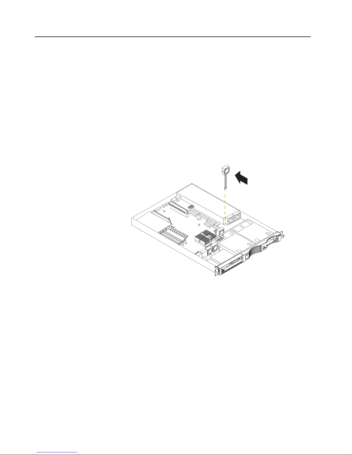
Chapter 5. Installing options 45
Replacing the fan assembly
Complete the following steps to replace the fan assembly:
1. Review the information in “Before you begin” on page 29.
2. Turn off the server and peripheral devices.
3. Remove all external cables from the server; then, remove the server from the rack
and remove the cover. For more information, see “Removing the cover” on page
37 for instructions.
4. Remove the fan from the server:
a. Disconnect the fan cable from the system board.
b. Lift the fan away from the server.
5. Orientate the fan so that the air flow arrow on the side of the fan is facing or
pointing toward the rear of the server.
Note: Proper air flow is from the front to the rear of the server.
6. Push the replacement fan assembly into the server until it clicks into place.
7. Connect the fan cable to the system board.
8. If you have other options to install or remove, do so now.
9. Replace the cover. See “Installing the cover” on page 46.
10. Reconnect the external cables and power cords; then, turn on the peripheral
devices and the server.
Air flow
Page 60

46 xSeries 300: User’s Reference
Installing the cover
Complete the following steps to install the server cover:
1. Install the cover by placing it into position and sliding it forward. Make sure that
the cover engages the tabs at the front and rear of the server.
Attention: Before sliding the cover forward, place it over 80% of the server, to
ensure that the cables are covered and all of the tabs will engage the front edge of
the server properly.
2. Install the screws to secure the cover as shown.
3. Reinstall the server in the rack. See the "Rack installation instuctions" included
with your server documentation for instructions.
4. Reconnect the power cord and all external cables to the server, and then plug the
power cords into properly grounded electrical outlets. See “Rear view” on page 7
for connector locations.
Screws
Page 61

Chapter 5. Installing options 47
I/O connectors
Your server has the following I/O connectors:
• Serial connector
• Universal Serial Bus (USB) connectors
• Keyboard connector
• Video connector
• Auxiliary-device (pointing device) connector
• Ethernet connectors
Serial port
Your server has one standard serial port. Some application programs require specific
ports, and some modems function properly only at certain serial port addresses. Use
the Configuration/Setup Utility program to change the port address assignments and
prevent conflicts.
Viewing or changing the serial-port assignments
To view or change the serial-port assignments:
1. Restart the server and watch the monitor screen.
2. When the message Press F1 for Configuration/Setup appears, press F1.
3. From the main menu, select Devices and I/O Ports; then, press Enter.
Note: The Devices and I/O Ports choice appears only on the full configuration
menu. If you set two levels of passwords, you must enter the administrator
password to access the full configuration menu.
Ethernet 1 connector
Ethernet 2 connector
Serial
connector
USB 1
USB 2
Video
connector
Mouse or auxiliary
pointing device connector
Keyboard connector
Table 1. Serial port connector on the system board.
Connector Port Description
COM1 Serial port connector (external) Default connection. Used by the
operating system. The modem
can be connected so that the
system can dial out during
problems.
Page 62

48 xSeries 300: User’s Reference
4. Select the serial port; then, use the arrow keys to advance through the settings
available.
5. Select Save Settings; then, select Exit Setup to exit from the
Configuration/Setup Utility main menu.
Serial-port connector
Your server has one serial-port connector located on the rear of the server.
The following table and illustration shows the pin-number assignments for the 9-pin,
male D-shell serial-port connector on the rear of your server. These pin-number
assignments conform to the industry standard.
Universal Serial Bus ports
Your server has two Universal Serial Bus (USB) ports, which configure automatically.
USB is an emerging serial interface standard for telephony and multimedia devices. It
uses Plug and Play technology to determine the type of device attached to the
connector.
USB cables and hubs
You need a 4-pin cable to connect devices to USB 1 or USB 2. If you plan to attach
more than two USB devices, you must use a hub to connect the devices. The hub
provides multiple connectors for attaching additional external USB devices.
USB technology provides up to 12 megabits-per-second (Mbps) speed with a
maximum of 127 external devices and a maximum signal distance of five meters (16
ft). per segment.
Table 2. Serial-port connector pin-number assignments.
Pin Signal Pin Signal
1 Data carrier detect 6 Data set ready
2 Receive data 7 Request to send
3 Transmit data 8 Clear to send
4 Data terminal ready 9 Ring indicator
5 Signal ground
1
5
69
Page 63
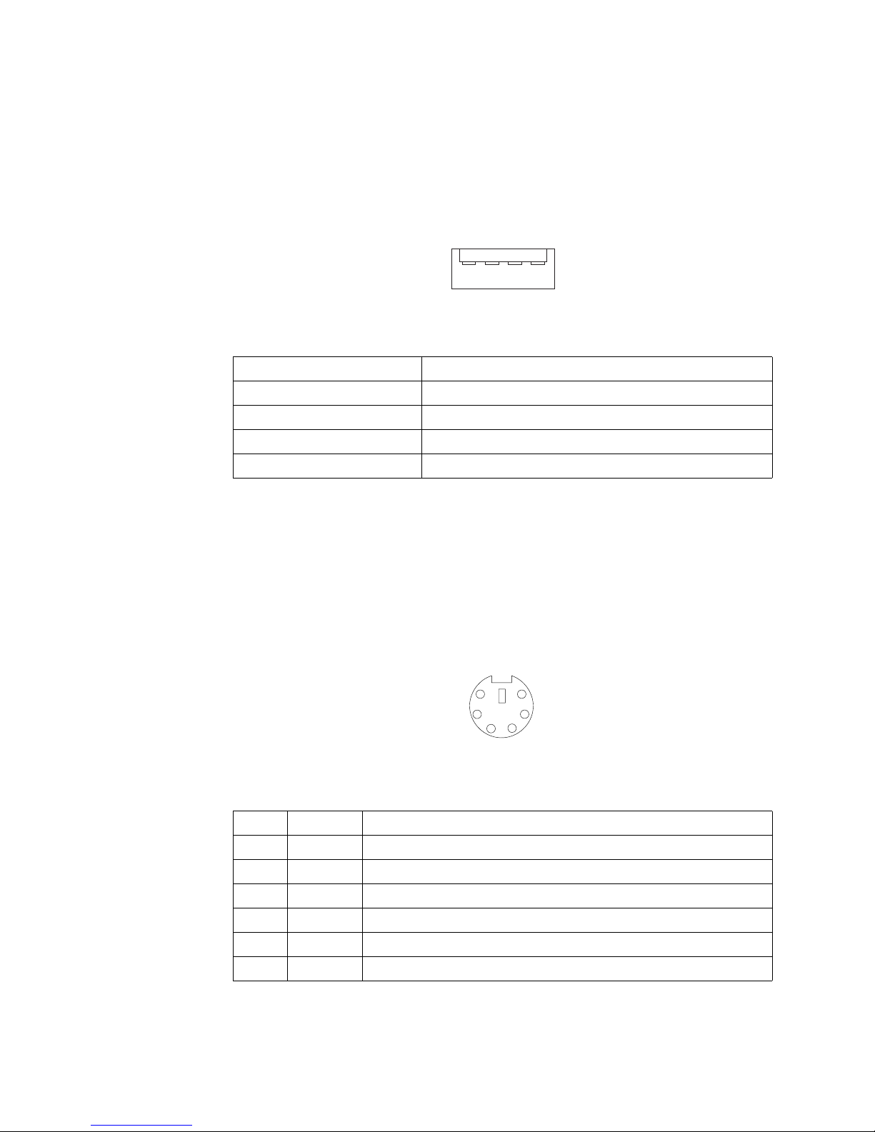
Chapter 5. Installing options 49
USB-port connectors
Each USB port has an external connector on the rear of the server for attaching USBcompatible devices.
The following table and illustration show the pin-number assignments for the USB-port
connectors on the rear of your server.
Keyboard connector
There is one keyboard connector on the rear of the server.
Note: If you attach a standard keyboard to the keyboard connector, the USB ports,
and devices will be disabled during the power-on self-test (POST).
The following table and illustration shows the pin-number assignments for the
keyboard connector on the end of the cable.
Table 3. USB-port connector pin-number assignments.
Pin Signal
1VCC
2-Data
3+Data
4 Ground
14
Table 4. Keyboard-connector (6-pin female) number assignments .
Pin I/O Signal
1I/O Data
2N/A Reserved
3 N/A Ground
4 N/A +5 V dc
5 I/O Keyboard clock
6N/A Reserved
6
4
2
1
3
5
Page 64
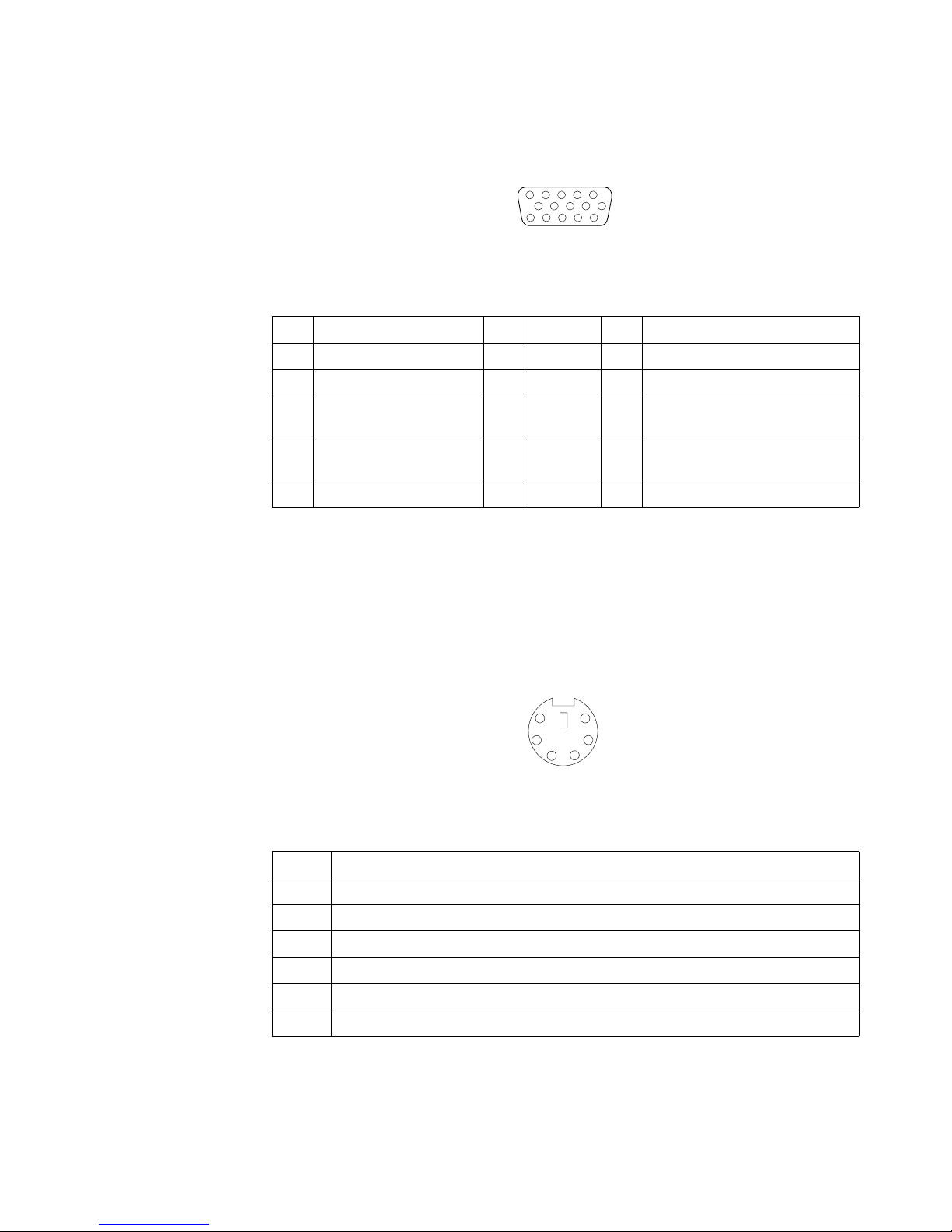
50 xSeries 300: User’s Reference
Video connector
The following table shows the pin-number assignments for the 15-pin analog video
connector on the rear of the server.
Auxiliary-device (pointing device) connector
There is one auxiliary-device connector that supports a mouse or other pointing
device located on the rear of the server just under the keyboard connector.
The following table shows the pin-number assignments for the auxiliary-device
connector on the end of the cable.
Table 5. Video-connector (15-pin female) number assignments.
Pin Signal Pin Signal Pin Signal
1 Red 6 Ground 11 Not connected
2 Green or monochrome 7 Ground 12 DDC SDA
3 Blue 8 Ground 13 Horizontal synchronization
(Hsync)
4 Not connected 9 +5 V dc
DDC
14 Vertical synchronization (Vsync)
5 Ground 10 Ground 15 DDC SCL
1
5
1115
Table 6. Auxiliary or pointing-device-connector (6 pin female) number assignments .
Pin Signal
1Data
2 Not connected
3Ground
4+5 V dc
5Clock
6 Not connected
6
4
2
1
3
5
Page 65

Chapter 5. Installing options 51
Ethernet ports
Your server comes with two integrated Ethernet controllers. These controllers provide
an interface for connecting to 10-Mbps or 100-Mbps networks and provide full-duplex
(FDX) capability, which enables simultaneous transmission and reception of data on
the Ethernet local area network (LAN).
To access the Ethernet ports, connect a Category 3, 4 or 5 unshielded twisted-pair
(UTP) cable to the RJ-45 connector on the rear of your server.
Note: The 100BASE-TX Fast Ethernet standard requires that the cabling in the
network be Category 5 or higher.
Configuring the Ethernet controllers
When you connect your server to the network, the Ethernet controllers automatically
detect the data-transfer rate (10Mbps or 100Mbps) on the network and then set the
controllers to operate at the appropriate rate. In addition, if the Ethernet ports that
your server is connected to support auto-negotiation, the Ethernet controllers will set
the appropriate duplex state. That is, the Ethernet controllers will adjust to the network
data rate, whether the data rate is standard Ethernet (10BASE-T), Fast Ethernet
(100BASE-TX), half duplex (HDX), or full duplex (FDX). The controllers support halfduplex (HDX) and full-duplex (FDX) modes at both speeds.
The Ethernet controllers are PCI Plug and Play devices. You do not need to set any
jumpers or configure the controllers for your operating system before you use the
Ethernet controllers. However, you must install a device driver to enable your
operating system to address the Ethernet controllers. The device drivers are provided
on the ServerGuide CDs.
Failover for redundant Ethernet
The IBM 10/100 Ethernet Adapter or the IBM 10/100 EtherJet PCI family of adapters
are optional redundant network interface cards (NICs) that you can install in your
server. If you install this NIC and connect it to the same logical segment as the
primary Ethernet controller, you can configure the server to support a failover function.
You can configure either one of the integrated Ethernet controllers or the NIC as the
primary Ethernet controller. In failover mode, if the primary Ethernet controller detects
a link failure, all Ethernet traffic associated with it is switched to the redundant
(secondary) controller. This switching occurs without any user intervention. When the
primary link is restored to an operational state, the Ethernet traffic switches back to
the primary Ethernet controller.
Page 66

52 xSeries 300: User’s Reference
High Performance Ethernet Modes
Your Ethernet controllers support optional modes, such as teaming, priority packets,
and virtual LANs, which provide higher performance and throughput for your server.
Teaming Mode: Your Ethernet controllers provide options, called teaming options.
These options increase throughput and fault tolerance when running with Windows
NT 4.0 or NetWare 4.1x or later.
• Adapter fault tolerance (AFT) provides automatic redundancy for your adapter.
If the primary adapter fails, the secondary adapter takes over. Adapter fault
tolerance supports from 2 to 4 adapters per team.
• Adaptive load balancing (ALB) enables you to balance the transmission data
flow among 2 to 4 adapters. ALB also includes the AFT option. You can use ALB
with any 100BASE-TX switch.
• Cisco Fast EtherChannel (FEC) creates a team of 2 to 4 adapters to increase
transmission and reception thoughput. FEC also includes the AFT option. You can
only use FEC with a switch that has FEC capability.
Teaming requires you to install both integrated Ethernet controllers. For additional
information about the teaming modes, refer to the documentation that comes with
these additional adapters.
Priority Packet Mode: Priority Packet is a traffic-prioritization utility that enables you
to set up filters to process high-priority traffic before normal traffic. You can send
information from critical nodes or applications with an indicated priority. Because you
set this priority at the host or entry point of the network, the network devices can base
forwarding decisions on priority information defined in the packet.
Priority Packet information is available on the IBM Networking Web site at:
http://www.ibm.com/networking/support.
Priority Packet prioritizes traffic based on priority filters. These are parameters you
assign to outgoing (transmit) packets. Using the Priority Filter Wizard, you can set up
predefined or custom priority filters based on a node (MAC) address, Ethernet type, or
by various properties of the protocol and port. Priority Packet provides two different
methods for prioritizing traffic: IEEE 802.1p tagging and High Priority Queue.
IEEE 802.1p is a new IEEE standard for tagging, or adding additional bytes of
information to packets with different priority levels. Packets are tagged with 4
additional bytes, which increase the packet size and indicate a priority level. When
you send these packets out on the network, the higher priority packets are transferred
first. Priority packet tagging (also known as Traffic Class Expediting) enables the
adapter to work with other elements of the network (such as switches and routers) to
deliver priority packets first. You can assign specific priority levels from 0 (low) to 7
(high).
You can assign values to packets based on their priority when you use the IEEE
802.1p standard for packet tagging. This method requires a network infrastructure that
supports packet tagging. The routing devices receiving and transferring these packets
on your network must support 802.1p for tagging to be effective.
Page 67

Chapter 5. Installing options 53
After you set up the priority filter in Priority Packet, you must launch IBMSet and select
802.1p/802.1Q Tagging on the Advanced tab.
Note: IEEE 802.1p tagging increases the size of the packets it tags. Some hubs and
switches will not recognize the larger packets and will drop them. Check your
hub or switch documentation to see if they support 802.1p. (You can configure
the switch to strip the tags from the packets and send it on to the next
destination as normal traffic). If these devices do not support 802.1p or if you
are not sure, use High Priority Queue (HPQ) to prioritize network traffic.
The requirements for effectively using IEEE 802.1p tagging are:
• The other devices receiving and routing 802.1p tagged packets must support
802.1p.
• The adapters on these devices must support 802.1p. The Ethernet controller in
your server, all IBM Netfinity 10/100 Ethernet Security Adapters, and IBM 10/100
Ethernet Server Adapters support 802.1p.
• The adapter cannot be assigned to an adapter team.
• If you are setting up Plans and packet tagging on the same adapter,
802.1p/802.1Q Tagging must be enabled on the IBMSet Advanced tab.
If your network infrastructure devices do not support IEEE 802.1p or you are not sure,
you can still define filters and send packets as high priority. While High Priority Queue
(HPQ) does not provide the precise priority levels of 802.1p tagging, it does assign
traffic as either high or low priority and sends high priority packets first. Therefore, if
there are multiple applications on a system sending packets, the packets from the
application with a filter are sent out first. HPQ does not change network routing, nor
does it add any information to the packets.
To assign HPQ, you can specify it using Priority Packet when you create or assign a
filter.
To effectively use HPQ, the adapter cannot be assigned to an adapter team.
Virtual LAN Mode: A virtual LAN (VLAN) is a logical grouping of network devices put
together as a LAN, regardless of their physical grouping or collision domains. Using
Plans increases network performance and improves network security.
Vlans offer you the ability to group users and devices together into logical workgroups.
This can simplify network administration when connecting clients to servers that are
geographically dispersed across the building, campus, or enterprise network.
Page 68

54 xSeries 300: User’s Reference
Normally, Vlans are configured at the switch and any computer can be a member of
one VLAN per installed network adapter. Your Ethernet controller supersedes this by
communicating directly with the switch, allowing multiple VLANs on a single network
adapter (up to 64 VLANs).
To set up VLAN membership, your Ethernet controller must be attached to a switch
that has VLAN capability. You also need to use Windows NT 4.0 or later, or Novell
NetWare 4.1x or later.
Page 69

Chapter 5. Installing options 55
Notes:
1. Windows NT versions prior to 4.0 do not support VLANs.
2. VLANs require NT 4.0 with Service Pack 3.0 and the NDIS driver from Microsoft.
3. In Windows NT, VLANs cannot be implemented on controllers that have been
configured for teaming options. NetWare can support teaming options and VLANs
on the same adapters.
To join a VLAN from Windows NT 4.0:
1. Create a VLAN on the switch. Use the parameters you assign there to join the
VLAN from the server. Refer to your switch documentation for more information.
2. Double-click the Network icon in the Control Panel window.
3. On the Adapters tab, select the adapter you want to be on the VLAN and select
Properties.
4. In IBMSet, select Join VLAN. Note that VLANs cannot be assigned to adapters
that are already defined to have an adapter teaming option.
5. Enter the VLAN ID and VLAN name. The VLAN ID must match the VLAN ID of the
switch. The ID range is from 1 to 1000. The VLAN name is for information only
and does not need to match the name on the switch.
6. Select Join VLAN. Repeat steps 3 through 5 for each VLAN you want the server
to join. The VLANs you add are listed on the Adapters tab.
7. Select Close and restart the computer.
Ethernet port connector
The following table and illustration show the pin-number assignments for the RJ-45
connector. These assignments apply to both 10BASE-T and 100BASE-TX devices.
Table 7. Ethernet RJ-45 connector pin-number assignments..
Pin Signal Pin Signal
1 Transmit data+ 5 Not connected
2 Transmit data- 6 Receive data -
3 Receive data+ 7 Not connected
4 Not connected 8 Not connected
Page 70

56 xSeries 300: User’s Reference
Page 71

© Copyright IBM Corp. 2001 57
Chapter 6. Solving problems
This section provides basic troubleshooting information to help you resolve some
common problems that might occur with your system.
If you cannot locate and correct the problem using the information in this section, refer
to “Getting help, service, and information” on page 95 for more information.
Diagnostic tools overview
The following tools are available to help you identify and resolve hardware-related
problems:
• POST beep codes
The power-on self-test beep codes indicate the detection of a problem. See
“POST beep code descriptions” on page 59 for more information.
• Diagnostic programs and error messages
The system diagnostic programs are provided on the IBM Enhanced Diagnostics
CD. These programs test the major components of your server. See “Diagnostic
programs and error messages” on page 70 for more information.
• Troubleshooting charts
These charts list problem symptoms and steps to correct the problems. See the
“Troubleshooting charts” on page 81 for more information.
• Customized support page
You can create a customized support page on the World Wide Web that is specific
to your hardware, including frequently asked questions, parts information,
technical hints and tips, and downloadable files. In addition, you can choose to
receive electronic mail (e-mail) notifications whenever new information becomes
available about your registered products.
After you register and profile your xSeries 300, you can diagnose problems using
the IBM Online Assistant, and you can participate in the IBM discussion forum.
For more detailed information about registration and creating a customized profile
for your IBM products, visit the following addresses on the Web:
— http://www.ibm.com/pc/register
— http://www.ibm.com/pc/support
Page 72

58 xSeries 300: User’s Reference
Server Support
After you register and profile, you will be able to:
• Diagnose problems using the IBM Online Assistant
• Participate in the IBM discussion forum
• Receive e-mail notifications of technical updates
related to your profiled products
Register at:
Profile at:
http://www.ibm.com/pc/register
http://www.ibm.com/pc/support
Register and profile your server
Ye s
No
No
Phone an
IBM HelpCenter
Use the troubleshooting
information provided with
your server to determine
the cause of the problem
and the action to take.
Flash the latest levels of BIOS.
You can download this code at:
http://www.ibm.com/pc/support
No
No
Ye s
Ye s
Ye s
Check all cables for loose connections
and verify that all optional devices you
installed are on the ServerProven list.
You can view the ServerProven list at:
®
http://www.ibm.com/pc/compat
Server working
properly?
Problem
solved?
Problem
solved?
Problem
solved?
You can view a list of
IBM HelpCenter phone numbers at:
®
http://www.ibm.com/pc/support
Page 73

Chapter 6. Solving problems 59
POST
When you turn on the server, it performs a series of tests to check the operation of
system components and some of the options that are installed in the server. This
series of tests is called the power-on self-test, or POST.
If POST finishes without detecting any problems, the first window of your operating
system or application program appears.
Notes:
1. If you have a power-on password set, you must type the password and press
Enter, when prompted, before POST will continue.
2. A single problem might cause several error messages. When this occurs, work to
correct the cause of the first error message. After you correct the cause of the first
error message, the other error messages usually will not occur the next time you
run the test.
POST beep code descriptions
Beep codes are sounded in a series of beeps. For example, a 1-2-4 beep code
sounds like one beep, a pause, two consecutive beeps, another pause, and four more
consecutive beeps.
The possible types of beep codes that your server might emit include the following:
No beeps
If no beep occurs after your server completes POST, call for service.
Continuous beep
Your startup (boot) microprocessor has failed, or your system board or
speaker subsystem might contain a failing component. If the system
continues through POST with no errors, call for service. If no video appears,
the startup processor has failed; replace the startup processor.
One short beep
One beep indicates that your server successfully completed POST. POST
detected no configuration or functional errors. One beep also occurs after
your server completes POST if you enter an incorrect power-on password.
Two short beeps
POST encountered an error. The Configuration/Setup Utility program will
display additional information; follow the instructions that appear on the
screen. See “POST error messages” on page 62 for descriptions of the text
messages that might appear.
Three short beeps
A system memory error has occurred. This combination occurs only if the
video Basic Input/Output System (BIOS) cannot display the error message.
Replace the failing memory module.
Repeating short beeps
The system board might contain a failing component, your keyboard might be
defective, or a key on the keyboard might be stuck. Ensure that:
1. Nothing is resting on the keyboard and pressing a key.
2. No key is stuck.
3. The keyboard cable is connected correctly to the keyboard and to the
correct connector on the server.
Running the diagnostic tests can isolate the server component that failed, but
you must have your system serviced. If the error message remains, call for
service.
Page 74

60 xSeries 300: User’s Reference
Note: If you just connected a new mouse or other pointing device, turn off
the server and disconnect that device. Wait at least 5 seconds; then,
turn on the server. If the error message goes away, replace the device.
One long and one short beep
POST encountered an error on a video adapter. If you are using the
integrated video controller, call for service. If you are using an optional video
adapter, replace the failing video adapter.
One long and two short beeps
A video I/O adapter ROM is not readable, or the video subsystem is defective.
If you hear this beep combination twice, both the system board and an
optional video adapter have failed the test. This beep combination might also
indicate that the system board contains a failing component.
One long and three short beeps
The system-board video subsystem has not detected a monitor connection to
the server. Ensure that the monitor is connected to the server. If the problem
persists, replace the monitor.
Two long and two short beeps
POST does not support the optional video adapter. This beep combination
occurs when you install a video adapter that is incompatible with your server.
Replace the optional video adapter with one that the server supports or use
the integrated video controller.
Page 75

Chapter 6. Solving problems 61
Table 8. POST beep codes.
Beep Code Description Action
1-1-2 Microprocessor register test has failed. Call for service
1-1-3 CMOS write/read test has failed.
1-1-4 BIOS ROM checksum has failed.
1-2-1 Programmable Interval Timer test has failed.
1-2 -2 DMA in it ia li za ti on ha s fail ed .
1-2-3 DMA page register write/read test has failed.
1-4-3 Interrupt vector loading test has failed.
2-1-1 Secondary DMA register test has failed.
2-1-2 Primary DMA register test has failed.
2-1-3 Primary interrupt mask register test has
failed.
2-1-4 Secondary interrupt mask register test has
failed.
2-2-1 Interrupt vector loading has failed.
2-2-2 Keyboard controller test has failed.
2-2-3 CMOS power failure and checksum checks
have failed.
2-2-4 CMOS configuration information validation
has failed.
2-3-2 Screen memory test has failed.
2-3-3 Screen retrace tests have failed.
2-3-4 Search for video ROM has failed.
2-4-1 Screen test indicates the screen is operable.
3-1-1 Timer tick interrupt test has failed.
3-1-2 Interval timer channel 2 test has failed.
3-1-3 RAM test has failed above address hex
0FFFF.
3-1-4 Time-of-Day clock test has failed.
3-2-1 Serial port test has failed.
3-2-2 Parallel port test has failed.
3-2-4 Comparison of CMOS memory size against
actual has failed.
3-3-2 I2C bus has failed.
2-3-1 Screen initialization has failed. Turn off the server and then
restart the server. If the
problem remains, call for
service.
Page 76

62 xSeries 300: User’s Reference
POST error messages
The following tables provide information about the POST error messages that can
appear during startup.
POST message Description
062 The server failed to boot on three consecutive attempts.
All caches are disabled. Repeatedly turning the server on and then off or resetting the server
might cause this problem.
Action: Start the Configuration/Setup Utility program and verify that all settings are correct.
Use the Cache Control selection in the Advanced Setup menu of the
Configuration/Setup Utility program to enable the caches.
If the problem remains, call for service. When the problem is corrected, be sure to enable the
caches.
101 102 106 An error occurred during the system board and microprocessor test.
Action: Call for service.
114 An adapter read-only memory (ROM) error occurred.
Action: Remove the options. If you can start the server without the options installed, reinstall
each option one at a time and retest after each is reinstalled. When an option fails,
replace it.
If you cannot isolate and correct the problem, call for service.
129 An error was detected in the L1 cache of one of the microprocessors.
Action: 1. If you just installed a microprocessor, verify that the microprocessor is installed
and seated correctly.
2. If the problem remains, call for service.
151 A real-time clock (RTC) error occurred.
Action: Call for service.
161 The real-time clock battery has failed.
Action: Replace the battery yourself or call for service.
You can use the server until you replace the battery. However, you must run the
Configuration/Setup Utility program and set the time and date and other custom settings each
time you turn on the server.
162 A change in device configuration occurred. This error occurs under one or more of the following
conditions:
• A new device has been installed.
• A device has been moved to a different location or cable connection.
• A device has been removed or disconnected from a cable.
• A device is failing and is no longer recognized by the server as being installed.
• An external device is not turned on.
• An invalid checksum is detected in the battery-backed memory.
Action: Verify that all external devices are turned on. You must turn on external devices before
turning on the server.
If you did not add, remove, or change the location of a device, a device is probably failing.
Running the Diagnostic program might isolate the failing device.
If you cannot isolate and correct the problem, call for service.
Table 9. POST error messages.
Page 77

Chapter 6. Solving problems 63
163 The time of day has not been set.
Action: Set the correct date and time. If the date and time are set correctly and saved, but the
163 error message reappears, call for service.
You can use the server until the system is serviced, but any application programs that use the
date and time will be affected.
164 A change in the memory configuration occurred. This message might appear after you add or
remove memory.
Note: The server can be used with decreased memory capacity.
Action: 1. If POST error message 289 also occurred, follow the instructions for that error
message first.
2. If you just installed or removed memory, run the Configuration/Setup Utility
program; then, exit, saving the new configuration settings.
If the message appears again, shut down the server, reset the memory modules,
and restart the server.
If the problem remains, call for service.
175 A vital product data (VPD) error occurred.
Action: Call for service.
176 177 178 A security hardware error occurred.
Action: Check for indications that someone has tampered with the server. If no one has
tampered with the server, call for service.
184 The power-on password information stored in your server has been removed.
Action: From the Configuration/Setup Utility program main menu, select System Security.
Then, follow the instructions on the screen.
If this information cannot be restored, call for service.
185 A power failure damaged the stored information about the drive-startup sequence.
Action: From the Configuration/Setup Utility program main menu, select Start Options; then,
follow the instructions on the screen.
If this information cannot be restored, call for service.
186 A system board or hardware error occurred.
Action: Call for service.
187 The VPD serial number is not set.
Action: The system serial number is set in the VPD EEPROM at the time of manufacturing. If
the system board has been replaced, the system serial number will be invalid and
should be set. From the main menu of the Configuration/Setup Utility program, select
System Information, then select Product Data.If the problem remains, call for
service.
188 A vital product data (VPD) error occurred.
Action: Call for service.
189 An attempt has been made to access the server with invalid passwords. After three incorrect
attempts, the server locks up; that is, the logon data fields are no longer available to the user.
POST message Description
Table 9. POST error messages.
Page 78

64 xSeries 300: User’s Reference
201 An error occurred during the memory controller test. This error can be caused by:
• Incorrectly installed memory
• A failing memory module
• A system board problem
Action: 1. If you just installed memory, verify that the new memory is correct for your server.
Also verify that the memory is installed and seated correctly.
2. If the problem remains, call for service.
229 An error was detected in the L2 cache of one of the microprocessors.
Action: 1. If you just installed a microprocessor, verify that the microprocessor is installed
and seated correctly.
2. If the problem remains, call for service.
289 An error occurred during POST memory tests and a failing DIMM was disabled.
Note: You can use the server with decreased memory.
Action: 1. If you just installed memory, verify that the new memory is correct for your server.
Also verify that the memory is installed and seated correctly. Start the
Configuration/Setup Utility program and select Memory Settings from the
Advanced Setup menu to enable the DIMM.
2. If the problem remains, replace the failing DIMM.
If the problem remains, call for service.
301 303 An error occurred during the keyboard and keyboard controller test. These error messages also
might be accompanied by continuous beeping.
Action: Ensure that:
1. Nothing is resting on the keyboard and pressing a key.
2. No key is stuck.
3. The keyboard cable is connected correctly to the keyboard and to the correct
connector on the server.
Running the diagnostic tests can isolate the server component that failed, but you must have
your system serviced. If the error message remains, call for service.
Note: If you just connected a new mouse or other pointing device, turn off the server and
disconnect that device. Wait at least 5 seconds; then, turn on the server. If the error
message goes away, replace the device.
602 Invalid diskette boot record
Action: 1. Replace the diskette.
2. If the problem persists, make sure that the diskette drive cables are correctly and
securely connected.
3. If the problem remains, replace the diskette drive.
If the problem remains, call for service.
604 An error occurred during a diskette drive test.
Action: 1. Verify that the Configuration/Setup Utility program correctly reflects the type of
diskette drive that you have installed.
2. Run the diagnostic tests. If the diagnostic tests fail, call for service.
662 A diskette drive configuration error occurred.
Action: If you removed a diskette drive, make sure that the diskette drive setting is correct in
the Configuration/Setup Utility program. If the setting is not correct, change it.
If the problem remains, call for service.
POST message Description
Table 9. POST error messages.
Page 79

Chapter 6. Solving problems 65
962 A parallel port configuration error occurred.
Action: If you changed a hardware option, make sure that the parallel port setting is correct in
the Configuration/Setup Utility program. If the setting is not correct, change it.
If the problem remains, call for service.
11xx An error occurred during the system-board serial port test.
Action: If you have a modem, serial printer, or other serial device attached to your server,
verify that the serial cable is connected correctly. If it is, use the following procedure:
1. Turn off the server.
2. Disconnect the serial cable from the serial port.
3. Wait five seconds; then, turn on the server.
If the POST error message does not reappear, either the serial cable or the device is probably
failing. See the documentation that comes with the serial device for additional testing
information.
If the POST error message reappears, call for service.
1162 The serial port configuration conflicts with another device in the system.
Action: 1. Make sure the IRQ and I/O port assignments needed by the serial port are
available.
2. If all interrupts are being used by adapters, you might need to remove an adapter
to make an interrupt available to the serial port, or force other adapters to share
an interrupt.
1600 The Advanced System Management processor is not functioning.
Action: 1. Verify that the jumpers for the system-management processor are set correctly.
2. Disconnect the server from all electrical sources, wait for 30 seconds, reconnect
the server to the electrical sources, and restart the server.
If the problem remains, call for service.
1601 An Advanced System Management Flash update is needed.
Action: Download and install the latest Advanced System Management flash update.
1800 A PCI adapter has requested a hardware interrupt that is not available.
Action: 1. Make sure that the PCI adapter and all other adapters are set correctly in the
Configuration/Setup Utility program. If the interrupt resource settings are not
correct, change the settings.
2. If all interrupts are being used by other adapters, you might need to remove an
adapter to make an interrupt available to the PCI adapter, or force other adapters
to share an interrupt.
POST message Description
Table 9. POST error messages.
Page 80

66 xSeries 300: User’s Reference
1962 No valid startup devices were found. The system cannot find the startup drive or operating
system.
Action: Be sure that the drive you want to start from is in the startup sequence.
1. Select Start Options from the Configuration/Setup Utility program main menu. If
you are unable to set the startup sequence, call for service.
2. Check the list of startup devices in the Startup device data fields. Is the drive you
want to start from in the startup sequence?
Yes Exit from this screen; then, select Exit Setup to exit the
Configuration/Setup menu. Go to step 3..
No Follow the instructions on the screen to add the drive; then, save the
changes and exit the Configuration/Setup menu. Restart the server.
3. Is an operating system installed?
Yes Turn off the server. Go to step 4..
No Install the operating system in your server; then, follow your operating
system instructions to shut down and restart the server.
4. During server startup, watch for messages indicating a hardware problem.
If the same error message appears, call for service.
2400 An error occurred during the testing of the video controller on the system board. This error can
be caused by a failing monitor, a failing system board, or a failing video adapter (if one is
installed).
Action: Verify that the monitor is connected correctly to the video connector. If the monitor is
connected correctly, call for service.
2462 A video memory configuration error occurred.
Action: Make sure that the monitor cables are correctly and securely connected to the server.
If the problem remains, call for service.
5962 An IDE CD-ROM configuration error occurred.
Action: Check the signal and power cable connections to the CD-ROM drive.
If the problem remains, call for service.
8603 An error occurred during the mouse (pointing device) controller test. The addition or removal of
a mouse, or a failing system board can cause this error.
Note: This error also can occur if electrical power was lost for a very brief period and then
restored. In this case, turn off the server for at least 5 seconds; then, turn it back on.
Action: Ensure that the keyboard and mouse (pointing device) are attached to the correct
connectors. If they are connected correctly, use the following procedure:
1. Turn off the server.
2. Disconnect the mouse from the server.
3. Turn on the server.
If the POST error message does not reappear, the mouse is probably failing. See the
documentation that comes with the mouse for additional testing information. If the problem
remains, replace the mouse or pointing device.
If the POST error message reappears, run the diagnostic tests to isolate the problem. If the
diagnostic tests do not find a problem and the POST error message remains, call for service.
00012000 Processor machine check.
Action: 1. Update the system BIOS.
2. If the problem persists, replace the microprocessor.
POST message Description
Table 9. POST error messages.
Page 81

Chapter 6. Solving problems 67
00019501 Processor 1 is not functioning.
Action: Replace microprocessor 1.
If the problem remains, call for service.
00019502 Processor 2 is not functioning.
Action: Replace microprocessor 2.
If the problem remains, call for service.
00019701 Processor 1 failed the built-in self test.
Action: Replace microprocessor 1.
If the problem remains, call for service.
00019702 Processor 2 failed the built-in self-test.
Action: Replace microprocessor 2.
If the problem remains, call for service.
00180100 A PCI adapter has requested memory resources that are not available
Action: 1. Make sure that the PCI adapter and all other adapters are set correctly in the
Configuration/Setup Utility program. If the memory resource settings are not
correct, change the settings.
2. If all memory resources are being used, you might need to remove an adapter to
make memory available to the PCI adapter. Disabling the adapter BIOS on the
adapter might correct the error. Refer to the documentation provided with the
adapter.
00180200 A PCI adapter has requested an I/O address that is not available, or the PCI adapter might be
defective.
Action: 1. Make sure that the I/O address for the PCI adapter and all other adapters are set
correctly in the Configuration/Setup Utility program.
2. If the I/O port resource settings are correct, the PCI adapter might be defective.
Call for service.
00180300 A PCI adapter has requested a memory address that is not available, or the PCI adapter might
be defective.
Action: 1. Make sure that the memory address for all other adapters are set correctly in the
Configuration/Setup Utility program. If the memory resource settings are not
correct, change the settings.
2. If the memory resource settings are correct, the PCI adapter might be defective.
Call for service.
00180400 A PCI adapter has requested a memory address that is not available.
Action: If all memory addresses are being used, you might need to remove an adapter to
make memory address space available to the PCI adapter. Disabling the adapter
BIOS on the adapter might correct the error. Refer to the documentation provided with
the adapter.
00180500 A PCI adapter ROM error occurred.
Action: Remove the PCI adapters. If you can start the server without the adapters, reinstall
each adapter one at a time and retest after each is reinstalled. When an adapter fails,
replace it.
If you cannot isolate and correct the problem, call for service.
POST message Description
Table 9. POST error messages.
Page 82

68 xSeries 300: User’s Reference
00180600 A PCI-to-PCI bridge error occurred. More than one PCI bus tried to access memory below
1MB.
Action: Remove the PCI adapter that has the PCI bridge. If you can start the server without
the adapter, reinstall and retest the adapter. If the adapter fails, replace it.
If you cannot isolate and correct the problem, call for service.
00180700 xxxxyyyy Planar PCI device does not respond or disabled by user. (Where xxxx is the PCI
vendor ID and yyyy is the PCI device ID.)
Action: Start the Configuration/Setup Utility program, select Devices and I/O Ports, and make
sure that the device is enabled. If the problem remains, call for service.
00180800 An unsupported PCI device is installed.
Action: Remove the PCI adapters. If you can start the server without the adapters, reinstall
each adapter one at a time and retest after each is reinstalled. When an adapter fails,
replace it.
If the problem remains, call for service.
00181000 PCI error.
Action: Remove the PCI adapters. If you can start the server without the adapters, reinstall
each adapter one at a time and retest after each is reinstalled. When an adapter fails,
replace it.
If the problem remains, call for service.
01295085 The ECC checking hardware test failed.
Action: Call for service.
01298001 No update data is available for processor 1.
Action: Update the system BIOS to a level that supports the microprocessors installed in the
server.
01298002 No update data is available for processor 2.
Action: Update the system BIOS to a level that supports the microprocessors installed in the
server.
01298101 The update data for processor 1 is incorrect.
Action: Update the system BIOS to a level that supports the microprocessors installed in the
server.
01298102 The update data for processor 2 is incorrect.
Action: Update the system BIOS to a level that supports the microprocessors installed in the
server.
01298200 Microprocessor speed mismatch
Action: The microprocessors installed do not run at the same speed; install microprocessors
with identical speeds.
I9990301 A hard disk drive error occurred.
Action: Call for service.
I9990305 POST could not find an operating system.
Action: Install an operating system. If you have already installed the operating system, check
the drive startup sequence. If the drive sequence is correct, run the diagnostic tests to
verify that the hard disk drive is functioning correctly. If there is a problem with the hard
disk drive (such as a bad sector), you might need to reinstall the operating system.
If you cannot reinstall the operating system, call for service.
POST message Description
Table 9. POST error messages.
Page 83

Chapter 6. Solving problems 69
I9990650 AC power has been restored.
Action: No action is required. This message appears each time AC power is restored to the
server after an AC power loss.
Other Numbers POST found an error.
Action: Follow the instructions on the screen.
POST message Description
Table 9. POST error messages.
Page 84

70 xSeries 300: User’s Reference
Small computer system interface messages (some models)
If you receive a SCSI error message while using the SCSISelect Utility, use the
following list to determine the possible cause of the error and what action to take.
Note: If your system does not have a hard disk drive, ignore any message that
indicates that the BIOS code is not installed.
One or more of the following might be causing the problem.
• A failing SCSI device (adapter or drive)
• An improper SCSI configuration
• Duplicate SCSI IDs in the same SCSI chain
• An improperly installed SCSI terminator
• A defective SCSI terminator
• An improperly installed cable
• A defective cable
Action:
Verify that:
• The external SCSI devices are turned on. External SCSI devices must be turned
on before the server.
• The cables for all external SCSI devices are connected correctly.
• The last device in each SCSI chain is terminated properly.
• The SCSI devices are configured correctly.
If the above items are correct, run the diagnostic programs to obtain additional
information about the failing device. If the error remains or recurs, call for service.
Diagnostic programs and error messages
The system diagnostic programs are stored on the IBM Enhanced Diagnostics CD.
These programs provide the primary methods of testing the major components of
your server.
Diagnostic error messages indicate that a problem exists; they are not intended to be
used to identify a failing part. Troubleshooting and servicing of complex problems that
are indicated by error messages should be performed by trained service personnel.
Sometimes the first error to occur causes additional errors. In this case, the server
displays more than one error message. Always follow the suggested action
instructions for the first error message that appears.
The following sections contain the error codes that might appear in the detailed test
log and summary log, when running the diagnostic programs.
The error code format is as follows:
fff-ttt-iii-date-cc-text message
where:
Page 85

Chapter 6. Solving problems 71
fff is the three-digit function code that indicates the function being
tested when the error occurred. For example, function code 089
is for the microprocessor.
ttt is the three-digit failure code that indicates the exact test failure
that was encountered. (These codes are for trained service
personnel and are described in the Hardware Maintenance
Manual.)
iii is the three-digit device ID. (These codes are for trained service
personnel and are described in the Hardware Maintenance
Manual.)
date is the date that the diagnostic test was run and the error
recorded.
cc is the check value that is used to verify the validity of the
information.
text message is the diagnostic message that indicates the reason for the
problem.
Text messages
The diagnostic text message format is as follows:
Function Name: Result (test specific string)
where:
Function Name is the name of the function being tested when the error occurred.
This corresponds to the function code given in the “Diagnostic
error message tables” on page 74.
Result can be one of the following:
Passed This result occurs when the diagnostic test
completes without any errors.
Failed This result occurs when the diagnostic test
discovers an error.
User Aborted This result occurs when you stop the
diagnostic test before it is complete.
Not Applicable This result occurs when you specify a
diagnostic test for a device that is not
present.
Aborted This result occurs when the test could not
proceed because of the system
configuration.
Warning This result occurs when a possible problem
is reported during the diagnostic test, such
as when a device that is to be tested is not
installed.
Test Specific String This is additional information that is used
to analyze the problem.
Starting the diagnostic programs
The IBM Enhanced Diagnostics programs will isolate your server hardware from
software that you have installed on your hard disk drive. The programs run
independently of the operating system, and must be run either from the CD or
diskette. This method of testing is generally used when other methods are not
Page 86

72 xSeries 300: User’s Reference
accessible or have not been successful in isolating a problem suspected to be
hardware related.
An IBM Enhanced Diagnostics CD comes with your server. You can also download
the latest image of the diagnostics from http://www.ibm.com/pc/support on the World
Wide Web.
Note: When using diagnostics with a USB keyboard and mouse attached, go into
Setup and enable USB emulation.
1. Press F1 Configuration/Setup
2. Select Devices and I/O Ports
3. Select USB Setup
4. Make sure USB Keyboard and Mouse are enabled.
Using the diagnostics CD
To start the IBM Enhanced Diagnostics using the CD, do the following:
1. Turn off your server and any peripheral devices.
2. Turn on all attached devices; then, turn on your server.
3. When Press F1 For Configuration/Setup appears, press the F1 key.
4. When the Configuration/Setup Utility menu appears, select Start Options.
5. From the Start Options menu, select Startup Sequence.
6. Note the device selected as the First Startup Device. Later, you must restore this
setting.
7. Select CD-ROM as the First Startup Device.
8. Press Esc two times to return to the Configuration/Setup Utility menu.
9. Place the IBM Enhanced Diagnostics CD in the CD-ROM drive.
10. Select Save & Exit Setup and follow the prompts. The diagnostics will load.
Follow the instructions on the screen to run the diagnostics.
Important:
When you finish running the diagnostics, remove the CD from the CD-ROM drive and
turn off the server. You must restore the First Startup Device to the original setting.
Use steps 2 through 8 of this procedure to do this.
Downloading the diagnostics program
Complete the following steps to download the latest image of the IBM Enhanced
Diagnostics from the World Wide Web and create a stretchable Enhanced
Diagnostics diskette:
1. Go to the following World Wide Web site: http://www.ibm.com/pc/support/
2. Download the diagnostics file for your server to a hard disk drive directory (not to
a diskette).
3. Go to a DOS prompt and change to the directory where the file was downloaded.
4. Insert a blank high-density diskette in diskette drive A.
5. Type filename a: where filename is the name of the file you downloaded from the
Web, and press Enter.
The downloaded file is self-extracting and will be copied to the diskette. When the
copy completes, you have a startable IBM Enhanced Diagnostics diskette.
Page 87

Chapter 6. Solving problems 73
Using the diagnostic diskette
Complete the following steps to start the IBM Enhanced Diagnostics using the
diagnostics diskette:
1. Turn off your server and any peripheral devices.
2. Insert the IBM Enhanced Diagnostics diskette into the diskette drive.
3. Turn on the peripheral devices; then, turn on your server.
4. Follow the instructions on the screen.
When the tests have completed, you can view the test log by selecting Utility from the
top of the screen.
If the test indicate that the hardware is working properly but the problem persists
during normal server operations, a software error might be the cause. If you suspect a
software problem, refer to the information that comes with the software package.
Viewing the test log
The test log records data about system failures and other pertinent information. The
test log will not contain any information until after the diagnostic program has run.
Note: If you already are running the diagnostic programs, begin with step 4.
Do the following to view the test log:
1. Insert the IBM Enhanced Diagnostics CD or diskette.
2. Turn on the system and watch the screen.
If the system is on, shut down your operating system and restart the system.
3. If a power-on password is set, the system prompts you for it. Type the appropriate
password; then, press Enter.
4. Run the diagnostic programs, and when the Diagnostic Programs screen
appears, select Utility.
5. Select View Test Log from the list that appears; then, follow the instructions on
the screen. You can save the test log to a file on a diskette or to your hard disk
drive.
Note: The system maintains the test-log data while the system is powered on.
When you turn off the power to the server, the test log is cleared.
Page 88

74 xSeries 300: User’s Reference
Diagnostic error message tables
The following tables provide descriptions of the error messages that might be listed in
the test log after you run the diagnostic programs.
Code Function Result Text message Action
001 Core system Failed Processor board, ECC Test Call for service.
System board
005 Video port Processor and system boards
011 Serial port Integrated serial port
015 USB interface Aborted Cannot test USB interface while it is in use.
Note: If you have a USB keyboard or mouse
attached, you cannot run the diagnostic
program for the USB interface.
N/A
Failed System board 1. Turn off the system.
2. Replace the USB
keyboard and mouse
with a standard
keyboard and mouse.
3. Turn on the system.
4. Run the diagnostic
test again.
020 PCI interface Failed System board Call for service.
030 SCSI interface Failed SCSI adapter in slot n failed register/counter/
power test
(where n is the slot number of the failing adapter)
Refer to the information
provided with the adapter
for instructions.
If the problem remains, call
for service.
SCSI controller on system board failed
register/counter/power test
Call for service.
075 Power supply Failed Voltage sensed by the system is out of range Call for service.
Page 89

Chapter 6. Solving problems 75
089 Microprocessor Failed Invalid microprocessor in slot xyz or BIOS setup
problem
(where xyz identifies the microprocessor that is
causing the error message)
1. Check the system
error log for the
related error
messages.
2. If your system does
not have the latest
level BIOS installed,
update the BIOS.
3. If the problem
remains, replace the
xyz microprocessor
and run the test again.
If the problem remains, call
for service.
Processor in socket id xyz is installed but not
functioning
(where xyz identifies the microprocessor that is
causing the error message)
Microprocessor in socket id xyz
(where xyz identifies the microprocessor that is
causing the error message)
1. Reseat the
microprocessor.
2. If the problem
remains, replace the
microprocessor.
If the problem remains, call
for service.
Processor in socket id xyz is defective
(where xyz identifies the microprocessor that is
causing the error message)
Replace the
microprocessor.
If the problem remains, call
for service.
Test setup error: Application microprocessor not
installed or BIOS setup problem
1. Verify that the
Application
microprocessor is
installed and seated
correctly.
2. If your system does
not have the latest
level BIOS installed,
update the BIOS.
3. If the problem
remains, replace the
Application
microprocessor and
run the test again.
If the problem remains, call
for service.
089 Microprocessor Failed VRM corresponding to microprocessor in socket
xyz is defective
(where xyz identifies the microprocessor whose
VRM is causing the error message)
Replace the VRM.
If the problem remains, call
for service.
VRM corresponding to microprocessor in socket
id xyz is not installed
(where xyz identifies the microprocessor whose
VRM is causing the error message)
Install a VRM.
If the problem remains, call
for service.
Code Function Result Text message Action
Page 90

76 xSeries 300: User’s Reference
175 System thermal Failed Fan # n
(where n is the number of the failing fan)
Replace the indicated fan.
Temperature sensed on processor board is out of
range
Call for service.
180 Status display Failed Any failure message Call for service.
201 System memory Failed DIMMs in location DIMM n
(where n is the number of the socket that
contains the failing DIMM)
1. Reseat the failing
DIMM.
2. If the problem
remains, replace the
DIMM.
If the problem
remains, call for
service.
Test setup error: Corrupt BIOS in ROM If your system does not
have the latest level BIOS
installed, update the BIOS
to the latest level.
If the problem remains, call
for service.
Test setup error: Corrupt DMI BIOS, information
in BIOS is not as expected
Code Function Result Text message Action
Page 91

Chapter 6. Solving problems 77
202 System cache Aborted Test setup error: BIOS cannot access VPD
information
If your system does not
have the latest level BIOS
installed, update the BIOS
to the latest level and run
the diagnostic program
again.
If the problem remains, call
for service.
Test setup error: Corrupt DMI BIOS, information
in BIOS is not as expected
Test setup error: No L2 cache detected on
microprocessor socket id xyz or BIOS setup
problem
(where xyz identifies the microprocessor that is
causing the error message)
1. If your system does
not have the latest
level BIOS installed,
update the BIOS to
the latest level
2. Run the diagnostic
program again.
3. If the problem
remains, replace the
failing processor.
If the problem remains, call
for service.
Test setup error: Unknown hardware problem
associated with microprocessor in socket id xyz.
(where xyz identifies the microprocessor that is
causing the error message)
Failed Microprocessor in socket ID xyz
(where xyz identifies the microprocessor that is
causing the error message)
1. Reseat the identified
microprocessor.
2. If the problem
remains, replace the
microprocessor.
If the problem remains, call
for service.
Warning Test setup error: Cache is disabled. Use system
setup to enable before retrying the test
Use the Cache Control
choice under the
Advanced Setup menu,
under the
Configuration/Setup Utility
program main menu, to
enable the cache.
If the problem remains, call
for service.
206 Diskette drive Failed Internal diskette drive bay Call for service.
215 CD-ROM Failed On system board. Call for service.
Aborted The CD-ROM drive is not present. Verify that the cables are
properly connected to the
CD-ROM drive. If the
problem remains, call for
service.
217 Hard disk drive Failed BIOS drive # n (where n is the drive bay number) Call for service.
301 Keyboard Failed On system-board keyboard test failed 1. Verify that the
keyboard cable is
connected.
2. If the problem
remains, replace the
keyboard cable.
If the problem remains, call
for service.
Code Function Result Text message Action
Page 92

78 xSeries 300: User’s Reference
302 Mouse Failed On system-board pointing device test failed. Replace the pointing
device. If the problem
remains, call for service.
305 Video monitor Any message Refer to the information
that came with the monitor.
405 Ethernet Failed In PCI slot n
(where n is the PCI slot number in which the
failing Ethernet adapter is installed)
Replace the Ethernet
adapter in slot n. If the
problem remains, call for
service.
On system board Call for service.
415 Analog/digital
modem
Not
applicable
No modem was detected 1. Verify that the modem
is properly attached to
the system.
2. If the problem
remains, replace the
modem.
If the problem remains, call
for service.
PCI modem detected, but not enabled 1. Change the
configuration to
enable the modem.
2. If the problem
remains, replace the
modem.
If the problem remains, call
for service.
Failed Modem reset failed Replace the modem.
If the problem remains, call
for service.
No dial tone detected 1. Make sure that the
phone line attached to
the modem has a dial
tone. (Connect a
phone to the line and
listen, if necessary.) If
there is no tone, have
the phone line
serviced.
2. If the problem
remains, replace the
modem.
If the problem remains, call
for service.
Code Function Result Text message Action
Page 93

Chapter 6. Solving problems 79
Recovering BIOS code
If the BIOS code has become damaged, such as from a power failure during a flash
update, you can recover the BIOS using the boot block jumper and a BIOS flash
diskette. The boot block jumper selects between normal BIOS mode and flash
recovery mode. In the normal position, the jumper will be installed on pins 2 and 3. In
the recovery position, the jumper will be installed on pins 1 and 2.
BIOS flash notes:
1. There are two BIOS flash modes, Server and Appliance. When in either of the two
BIOS flash modes, USB devices can be turned on or off again by doing the
following:
a. Press F1 Configuration/Setup
b. Select Devices and I/O Ports
c. Select USB Setup
d. Make sure USB Keyboard and Mouse are enabled.
2. If the only USB devices attached to the server are a keyboard and or mouse, and
they are not working; then, press F1 to run the Configuration/Setup utility. If the
problem persists then refer to
“A USB device does not work”, 85.
3. You can obtain a BIOS flash diskette from one of the following sources:
• Use the ServerGuide program to make a BIOS flash diskette.
• Download files to make a BIOS flash diskette from the World Wide Web. Go
to http://www.ibm.com/pc/support/, select IBM System Support, and then
make the selections for your system.
• Contact your IBM service representative.
Complete the following steps to recover the BIOS code:
1. Turn off the server and peripheral devices and disconnect all external cables and
power cords; then, remove the cover, see “Removing the cover” on page 37.
2. Locate jumper JROM1 on the system board.
Page 94
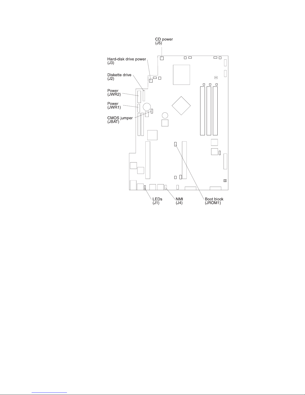
80 xSeries 300: User’s Reference
3. Move the JROM1 jumper to the alternate position (pins 1 and 2) to enable the
BIOS recovery mode.
4. Reinstall the cover, see “Installing the cover” on page 46.
5. Reconnect all external cables and power cords and turn on the peripheral
devices.
6. Insert the BIOS flash diskette in the diskette drive.
7. Restart the server. The BIOS begins the power-on self-test.
8. The BIOS flash utility automatically starts.
9. When prompted as to whether you want to save the current code to a diskette,
type N.
10. When prompted, type Y to continue the flash process.
11. The system automatically starts the flash utility a second time.
12. When prompted as to whether you want to save the current BIOS code, stop the
process by removing the BIOS flash diskette from the diskette drive.
13. Turn off the server and peripheral devices and disconnect all external cables and
power cords; then, remove the cover, see “Removing the cover” on page 37.
14. Move the JROM1 jumper to the normal position (pins 2 and 3) to return to normal
startup mode.
15. Reinstall the cover, see “Installing the cover” on page 46.
16. Reconnect all external cables and power cords and turn on the peripheral
devices.
Page 95

Chapter 6. Solving problems 81
17. Restart the server, which should start up normally.
Clearing CMOS
If you need to erase configuration information, you must move the CMOS jumper. See
the illustration in “Recovering BIOS code” on page 79 for the location of the CMOS
jumper.
The default position is a jumper installed on pins 1 and 2. Before you change the
position of this jumper, you must turn off the server and peripheral devices, and
disconnect all external cables and power cords. Remove the cover and then move the
jumper to pins 2 and 3.
After moving the jumper, wait at least 5 minutes for the CMOS information to clear.
Changing the position of this jumper erases all configuration and setup information,
including the power-on and administrator passwords. Therefore, you must reconfigure
the server after clearing CMOS memory (see Chapter 3, “Configuring your server,” on
page 13). If possible, record your server configuration information before moving the
CMOS jumper.
After you clear the CMOS information, move the jumper back to its normal position
(pins 1 and 2). Reconnect the external cables and power cords; then, turn on the
peripheral devices and the server.
Troubleshooting charts
You can use the troubleshooting charts in this section to find solutions to problems
that have definite symptoms.
Important: If diagnostic error messages appear that are not listed in the following
tables, make sure that your system has the latest levels of BIOS code installed.
See “Starting the diagnostic programs” on page 71 to test the system. If you have run
the diagnostic test programs or if running the tests does not reveal the problem, call
for service.
Look for the symptom in the left column of the chart. Instructions and probable
solutions to the problem are in the right column. If you have just added new software
or a new option and your system is not working, do the following before using the
troubleshooting charts:
• Remove the software or device that you just added.
• Run the diagnostic tests to determine if your system is running correctly.
• Reinstall the new software or new device.
Table 10. Troubleshooting charts.
Device Suggested action
CD-ROM drive Verify that:
1. The primary IDE channel is enabled in the Configuration/Setup Utility program.
2. All cables and jumpers are installed correctly.
3. The correct device driver is installed for the CD-ROM drive.
CD-ROM drive is not
recognized.
Page 96

82 xSeries 300: User’s Reference
Diskette drive If there is a diskette in the drive, verify that:
1. The diskette drive is enabled in the Configuration/Setup Utility program.
2. The diskette is good and not damaged. (Try another diskette if you have one.)
3. The diskette contains the necessary files to start the system.
4. Your software program is working properly.
If the diskette drive in-use light stays on, or the system continues to bypass the
diskette drive, call for service.
Diskette drive in-use light stays
on, or the system bypasses the
diskette drive.
Expansion enclosure Verify that:
1. The cables for all external SCSI options are connected correctly.
2. The last option in each SCSI chain, or the end of the SCSI cable, is terminated
correctly.
3. External SCSI options are turned on. You must turn on external SCSI options
before turning on the system.
For more information, see your SCSI and expansion enclosure documentation.
The SCSI expansion enclosure
used to work, but does not work
now.
Other devices Call for service.
Problems such as broken cover
locks or indicator lights not
working.
Intermittent problems Verify that:
1. All cables and cords are connected securely to the rear of the system and
attached options.
2. When the system is turned on, air is flowing from the rear of the system at the fan
grille. If there is no air flow, the fan is not working. This causes the system to
overheat and shut down.
3. Ensure that the SCSI bus and devices are configured correctly and that the last
external device in each SCSI chain is terminated correctly.
If the problem remains, call for service.
A problem occurs only
occasionally and is difficult to
detect.
Keyboard, mouse, or
pointing-device
1. Make sure that the keyboard cable is properly connected to the system.
2. Make sure that the system and the monitor are turned on.
3. Try using another keyboard.
If the problem remains, call for service.
All or some keys on the
keyboard do not work.
The mouse or pointing device
does not work.
1. Verify that the mouse or pointing-device cable is securely connected and the
device drivers are installed correctly.
2. Try using another mouse or pointing device.
If the problem remains, call for service.
Memory Verify that:
1. The memory modules are seated properly.
2. You have installed the correct type of memory.
3. If you changed the memory, you must update the memory configuration with the
Configuration/Setup Utility program.
4. All banks of memory on the DIMMs are enabled. The system might have
automatically disabled a DIMM bank if it detected a problem, or a DIMM bank
could have been manually disabled.
If the items above are correct and the screen remains blank, call for service.
The amount of memory
displayed is less than the
amount of memory installed.
Table 10. Troubleshooting charts.
Device Suggested action
Page 97

Chapter 6. Solving problems 83
Monitor Verify that:
1. The primary monitor cable is connected to the video port.
2. You installed the necessary device drivers for the applications.
Some IBM monitors have their own self-tests. If you suspect a problem with your
monitor, refer to the information that comes with the monitor for adjusting and testing
instructions.
If you still cannot find the problem, call for service.
The monitor works when you
turn on the system, but goes
blank when you start some
application programs.
The screen is blank. Verify that:
1. The system power cord is plugged into the server and a working electrical outlet.
2. The monitor cables are connected properly.
3. The monitor is turned on and the brightness and contrast controls are adjusted
correctly.
If the items above are correct and the screen remains blank, call for service.
Only the cursor appears. Call for service.
Wavy, unreadable, rolling,
distorted screen, or screen
jitter.
If the monitor self-tests show the monitor is working properly, consider the location of
the monitor. Magnetic fields around other devices (such as transformers, appliances,
fluorescent lights, and other monitors) can cause screen jitter or wavy, unreadable,
rolling, or distorted screen images. If this happens, turn off the monitor. (Moving a
color monitor while it is turned on might cause screen discoloration.) Then move the
device and the monitor at least 305 mm (12 in.) apart. Turn on the monitor.
Notes:
1. To prevent diskette drive read/write errors, be sure the distance between
monitors and diskette drives is at least 76 mm (3 in.).
2. Non-IBM monitor cables might cause unpredictable problems.
3. An enhanced monitor cable with additional shielding is available for the 9521 and
9527 monitors. For information about the enhanced monitor cable, see your IBM
reseller or IBM marketing representative.
If the problem remains, call for service.
Wrong characters appear on
the screen.
If the wrong language is displayed, update the BIOS code with the correct language.
If the problem remains, call for service.
Option Verify that:
1. The option is designed for the server. Refer to the "Server Support" flowchart for
information about obtaining ServerProven compatibility information from the
World Wide Web.
2. You followed the installation instructions that came with the option.
3. The option is installed correctly.
4. You have not loosened any other installed options or cables.
5. You updated the configuration information in the Configuration/Setup Utility
program. Whenever memory or an option is changed, you must update the
configuration.
If the problem remains, call for service.
An IBM option that was just
installed does not work.
Table 10. Troubleshooting charts.
Device Suggested action
Page 98

84 xSeries 300: User’s Reference
An IBM option that used to work
does not work now.
Verify that all of the option hardware and cable connections are secure.
If the option comes with its own test instructions, use those instructions to test the
option.
If the failing option is a SCSI option, verify that:
1. The cables for all external SCSI options are connected correctly.
2. The last option in each SCSI chain, or the end of the SCSI cable, is terminated
correctly.
3. All external SCSI options are turned on. You must turn on external SCSI options
before turning on the server.
If the problem remains, call for service.
Power Verify that:
1. The power cables are properly connected to the server.
2. The electrical outlet functions properly.
3. The type of memory installed is correct.
4. If you just installed an option, remove it, and restart the server. If the server now
turns on, you might have installed more options than the power supply supports.
5. The LEDs on the power supply are on.
If the problem remains, call for service.
The system does not power on.
The system does not power off. Verify if you are using an ACPI or non-ACPI operating system.:
If you are using a non-ACPI operating system:
1. Press Ctrl+Alt+Delete.
2. Turn off the system by using the power control button.
If the problem remains or if you are using an ACPI aware operating system, call for
service.
Serial port Verify that:
1. Each port is assigned a unique address by the Configuration/Setup Utility
program and none of the serial ports are disabled.
2. The serial-port adapter, if you installed one, is seated properly.
If the problem still exists, call for service.
The number of serial ports
identified by the operating
system is less than the number
of serial ports installed.
A serial device does not work. Verify that:
1. The device is compatible with the server.
2. The serial port is enabled and is assigned a unique address.
If the problem still exists, call for service.
Table 10. Troubleshooting charts.
Device Suggested action
Page 99

Chapter 6. Solving problems 85
Troubleshooting the Ethernet controller
This section provides troubleshooting information for problems that might occur with
the 10/100 Mbps Ethernet controller.
Network connection problems
If the Ethernet controller cannot connect to the network, check the following:
• Make sure that the cable is installed correctly.
The network cable must be securely attached at all connections. If the cable is
attached but the problem persists, try a different cable.
If you set the Ethernet controller to operate at 100 Mbps, you must use Category
5 cabling.
If you directly connect two workstations (without a hub), or if you are not using a
hub with X ports, use a crossover cable.
Note: To determine whether a hub has an X port, check the port label. If the label
contains an X, the hub has an X port.
• Determine if the hub supports auto-negotiation. If not, try configuring the
integrated Ethernet controller manually to match the speed and duplex mode of
the hub.
• Check the LAN activity light (if available) on the rear of the server. The LAN
activity light illuminates when the Ethernet controller sends or receives data over
the Ethernet network. If the LAN activity light is off, make sure that the hub and
network are operating and that the correct device drivers are loaded.
Software To determine if problems are caused by the software, verify that:
1. Your system has the minimum memory requirements needed to use the
software. For memory requirements, refer to the information that comes with the
software.
Note: If you have just installed an adapter or memory, you might have a
memory address conflict.
2. The software is designed to operate on your system.
3. Other software works on your system.
4. The software that you are trying to use works on another system.
If you received any error messages when using the software program, refer to the
information that comes with the software for a description of the messages and
solutions to the problem.
If the items above are correct and the problem remains, contact your place of
purchase.
Suspected software problem.
Universal Serial Bus (USB)
ports
Verify that:
1. You are not trying to use a USB device during POST, if you have a standard (nonUSB) keyboard attached to the keyboard port.
Note: If a standard (non-USB) keyboard is attached to the keyboard port, then
the USB is disabled and the USB device might not work during POST.
2. The correct USB device driver is installed.
3. Your operating system supports USB devices.
If the problem still exists, call for service.
A USB device does not work.
Table 10. Troubleshooting charts.
Device Suggested action
Page 100

86 xSeries 300: User’s Reference
• Make sure that you are using the correct device drivers, supplied with your
system.
• Check for operating system-specific causes for the problem.
• Make sure that the device drivers on the client and system are using the same
protocol.
• Test the Ethernet controller.
The way you test the Ethernet controller depends on which operating system you
are using (see the Ethernet controller device driver README file).
 Loading...