

Page 1

Overview of IBM Networking
The IBM networking technologies described in this publication can be categorized as network-related
or host-related technologies. The IBM Networking section of the Cisco IOS Bridging and IBM
Networking Configuration Guide discusses the following network-related software components:
• RSRB, page 202
• DLSw+, page 204
• STUN and BSTUN, page 211
• LLC2 and SDLC Parameters, page 215
• IBM Network Media Translation, page 217
• SNA FRAS, page 223
• NCIA, page 226
• ALPS, page 229
The IBM Networking section of the Cisco IOS Bridging and IBM Networking Configuration Guide
discusses the following host-related software and hardware components:
• DSPU and SNA Service Point, page 230
• SNA Switching Services, page 232
• Cisco Transaction Connection, page 239
• CMCC Adapter Hardware, page 242
The following Cisco IOS software features are supported on the CMCC adapters:
–
Common Link Access to Workstation, page 245
–
TCP/IP Offload, page 245
–
IP Host Backup, page 246
–
Cisco Multipath Channel+, page 246
–
Cisco SNA, page 247
–
Cisco Multipath Channel, page 248
–
TN3270 Server, page 248
This overview chapter gi v es a high-level description of each technology. For configuration information,
refer to the corresponding chapters in this publication.
78-11737-02
Cisco IOS Bridging and IBM Networking Configuration Guide
BC-201
Page 2
RSRB
S2327
RSRB
Overview of IBM Networking
Note All commands supported on the Cisco 7500 series routers are also supported on the Cisco 7000 series
routers.
In contrast to Source-Route Bridging (SRB), which involves bridging between Token Ring media only,
RSRB is a Cisco technique for connecting T ok en Ring networks o ver non-Token Ring network segments.
(DLSw+ is the Cisco strategic method for providing this function.)
The Cisco RSRB software implementation includes the following features:
• Provides for multiple routers separated by non-Token Ring segments. Three options are available:
–
Encapsulate the Token Ring traffic inside IP datagrams passed over a Transmission Control
Protocol (TCP) connection between two routers.
–
Use Fast-Sequenced Transport (FST) to transport RSRB packets to their peers without TCP or
User Datagram Protocol (UDP) header or processor overhead.
–
Use data link layer encapsulations over a single serial line, Ethernet, Token Ring, or Fiber
Distributed Data Interface (FDDI) ring connected between two routers attached to Token Ring
networks.
• Provides for configurable limits to the size of the TCP backup queue.
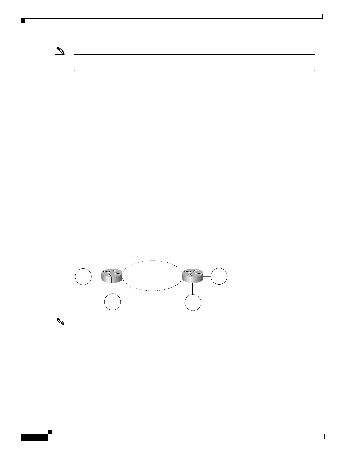
Figure 85 shows an RSRB topology. The virtual ring can extend across any non-Token Ring media
supported by RSRB, such as serial, Ethernet, FDDI, and WANs. The type of media you select determines
the way you set up RSRB.
Figure 85 RSRB Topology
Virtual ring
Token
Ring
Token
Ring
Note If you bridge across Token Ring media, it is recommended that you do not use RSRB. Use SRB
Non-Token Ring
Media
Token
Ring
Token
Ring
instead. Refer to the chapter “Configuring Source-Route Bridging” for more information.
BC-202
Cisco IOS Bridging and IBM Networking Configuration Guide
78-11737-02
Page 3

Overview of IBM Networking
Configuration Considerations
Use IP encapsulation only over a TCP connection within complex meshed networks to support
connections between peers that are separated by multiple hops and can potentially use multiple paths,
and where performance is not an issue. Use direct encapsulation in point-to-point connections. In a
point-to-point configuration, using TCP adds unnecessary processing overhead. Multiple peer types,
however, can be combined to in a single router by following the directions for each peer type. For
example, for a peer to support both TCP and FST remote-peers, you would need to define both a
source-bridge fst peername and a source-bridge remote-peer command for the local router, using the
same local IP address.
FST is fast-switched when it receives or sends frame s from Ethernet, Token Ring, or FDDI interfaces. It
is also fast-switched when it sends and receives from serial interfaces configured with the High-Level
Data Link Control (HDLC) encapsulat ion. In all other cases, FST is s low-switched.
In cases where FST is fast-switched, in either the Cisco routers configured for FST or in the routers
contained within the IP “cloud” between a pair of FST peers, only one path is used at a given time
between the two FST peers. A single path greatl y decrease s the likelihood that frames arrive out of
sequence. In the rare cases where frames do arrive out of sequence, the FST code on the receiving peer
discards the out-of-order frame. Thus the Token Ring end hosts rarely lose a frame over the FST router
cloud, and performance levels remain adequate.
The same conditions are true for any slow-switched topology that provides only a single path (for
example, a single X.25 network cloud) between the peers. Similarly, if two slow-switched paths are of
very different costs such that one always will be chosen over the other, the chances of having frames
received out of sequence are also rare.
RSRB
However, if two or more slow-switche d paths of eq ual cost exist be tween the two routers (such a s two
parallel X.25 networks), the routers alternate in s ending packets between the two or more equal-cost
paths. This results in a high probability of frames arri ving out of sequence at the recei v er. In such cases,
the FST code disposes of every out-of-sequence packet, leadi ng to a large number of drops. This requires
that the end hosts resend frames, greatly reducing overall throughput.
When parallel paths exist, we strongly recommend choosing one as the preferred path. Choose a
preferred path by specifying a higher bandw idth for th e path t hat con tains t he direct co nnec tions to the
two or more parallel paths on the router.
Do not use FST when the probability exists for frames to lose their order in your network. If you have a
network where frames are routinely reordered, it is better to use the TCP protocol for RSRB. TCP
provides the overhead necessary to bring frames back in order on the receiving router. FST, to remain
fast, does not provide for such a mechanism, and will discard out-of-order frames.
Logical Link Control, type 2 (LLC2) local acknowle dgment can be enabled only with TCP remote peers
(as opposed to LAN or direct serial interface remote peers) because the Cisco IOS software needs the
reliability of TCP to provide the same reliability that an LLC2 LAN end-to-end connection provides.
Therefore, the direct media encapsulation options for the source-bridge re mote-peer command cannot
be used.
If the LLC2 session between the local host and the router terminat es on either side of the co nnection, the
other device will be informed to terminate its connection to its local host.
If the TCP queue length of the connection between the two routers reaches 90 percent of its limit, they
send Receiver-not-Ready (RNR) messages to the local hosts until the queue limit is reduced to below
this limit.
The configuration of the LLC2 parameters for the local Token Ring interfaces can affect overall
performance. Refer to the “Configuring LLC2 and SDLC Parameters” chapter for more details about
fine-tuning your network through the LLC2 parameters.
78-11737-02
Cisco IOS Bridging and IBM Networking Configuration Guide
BC-203
Page 4

DLSw+
Overview of IBM Networking
Note As previously stated, local acknowledgment for LLC2 is meant only for extreme cases in which
communication is not possible otherwise. Because the router must maintain a full LLC2 session, the
number of simultaneous sessions it can support before performance degrades depends on the mix of
other protocols and their loads.
The routers at each end of the LLC2 session execute the full LLC2 protocol, which can result in some
overhead. The decision to turn on local acknowledgment for LLC2 should be based on the speed of the
backbone network in relation to the T ok en Ring speed. For LAN segments separated b y slow-speed serial
links (for example, 56 kbps), the T1 timer problem could occur more frequently. In such cases, it might
be wise to turn on local acknowledgment for LLC2. For LAN segments separated by a FDDI backbone,
backbone delays will be minimal; in such cases, local acknowledgment for LLC2 should not be turned
on. Speed mismatch between the LAN segments an d the backbone netw ork is on e criterio n to be used in
the decision to use local acknowledgment for LLC2.
There are some situations (such as host B failing between the time host A sends data and the time host
B receives it) in which host A would behave as if, at the LLC2 layer, data was received when it actually
was not, because the device acknowledges that it received data from host A before it confirms that host
B can actually receive the data. But because both NetBIOS and SNA have error recovery in situations
where an end device goes down, these higher-level protocols will resend any missing or lost data. These
transaction request/confirmation pr otocols e xist abo ve LLC2 , so the y are not af fected by ti ght timers, as
is LLC2. They also are transparent to local acknowledgment.
If you are using NetBIOS applications, note that there are two NetBIOS timers—one at the link level
and one at the next higher level. Local acknowledgment for LLC2 is designed to solv e session timeouts
at the link level only. If you are experiencing NetBIOS session timeouts, you have two options:
• Experiment with increasing your NetBIOS timers.
DLSw+
• Avoid using NetBIOS applications on slow serial lines.
In a configuration scenario where RSRB is configured between Router A and Router B and both routers
are not routing IP, a Host connected to router A through Token Ring (or other LAN media) has no IP
connectivity to router B. This restriction exists because IP datagrams received from the Host by Router
A are encapsulated and sent to router B where they can only be de-encapsulat ed and sourc e-bridged to
a Token Ring. In this scenario, IP routing is recommended. To enable the Host to reach Router B in this
scenario, IP routing should be enabled on Router A’s Token Ring interface to which the Host is attached.
Data-Link Switching Plus (DLSw+) is a method of transpo rting SN A and NetBIOS. It complies wi th the
DLSw standard documented in RFC 1795 and the DLSw Version 2 standard. DLSw+ is an alternative to
RSRB that addresses several inherent problems that exist in RSRB, such as:
• SRB hop-count limits (SRB’s limit is seven)
• Broadcast traffic (including SRB explorer frames or NetBIOS name queries)
• Unnecessary traffic (acknowledgments and keepalives)
• Data-link control timeouts
BC-204
Cisco IOS Bridging and IBM Networking Configuration Guide
78-11737-02
Page 5

Overview of IBM Networking
This section contains a brief overview of DLSw+:
DLSw Standard
The DLSw standard, documented in RFC 1795, defines the switch-to-switch protocol between DLSw
routers. The standard also defines a mechanism to terminate data-link control connections locally and
multiplex the traffic from the data-link control connections to a TCP connection. The standard always
calls for the transport protocol to be TCP and always requires that data-link control connections be
locally terminated (the equiv alent of the Cisco l ocal acknowled gment option). The standard also requi res
that the SRB RIF be terminated at the DLSw router. The standard describes a means for prioritization
and flow control and defines error recovery procedures that ensure data-link control connections are
appropriately disabled if any part of their associated circuits breaks.
The DLSw standard does not specify when to establish TCP connections. The capabilities exchange
allows compliance to the standard, bu t at different levels of support. The standard does not specify how
to cache learned information about MAC addresses, RIFs, or NetBIOS names. It also does not describe
how to track either capable or preferred DLSw partners for either backup or load-balancing purposes.The
standard does not provide the specifics of media conversion, but leaves the details up to the
implementation. It does not define how to map switch congestion to the flow control for data-link
control. Finally, the MIB is documented under a separate RFC.
DLSw+
• DLSw Standard, page 205
• DLSw Versio n 2 Standard, pa ge 205
• DLSw+ Features, page 206
DLSw Version 2 Standard
In the Version 1 standard, a network design requires fully meshed connectivity so that all peers were
connect to every other peer. This design creates unnecessary broadcast traffic because an explorer
propagates to every peer for every broadcast.
The Version 2 standard is documented in RFC 2166. It includes RFC 1795 and adds the following
enhancements:
• IP Multicast, page 206
• UDP Unicast, page 206
• Enhanced Peer-on-Demand Routing Feature, page 206
• Expedited TCP Connection, page 2 06
Users implement DLSw+ Version 2 for scalability if they are using multivendor DLSw devices with an
IP multicast network. DLSw Version 2 requires complex planning because it involves configuration
changes across an IP network.
78-11737-02
Cisco IOS Bridging and IBM Networking Configuration Guide
BC-205
Page 6

DLSw+
IP Multicast
UDP Unicast
Overview of IBM Networking
Multicast service avoids duplication and excessive bandwidth of broadcast traffic because it replicates
and propagates messages to its multicast members only as necessary. It re duces the amount of network
overhead in the following ways:
• A v oids the need to maintain TCP Switch-to-Switch Protocol (SSP) connections between two DLSw
peers when no circuits are available
• Ensures that each broadcast results in only a single explorer over every link
DLSw Version 2 is for customers who run a multicast IP network and do not need the advantages of
border peering.
DLSw Version 2 uses UDP unicast in response to a IP multicast. When address resolution packets
(CANUREACH_EX, NETBIOS_NQ_ex, NETBIOS_ANQ, and DATAFRAME) are sent to multiple
destinations (IP multicast service) DLSw Version 2 sends the response frames (ICANREACH_ex and
NAME_RECOGNIZED_ex) via UDP unicast.
Enhanced Peer-on-Demand Routing Feature
DLSw V ersion 2 establishes TCP connections only when necessary and the TCP connections are brought
down when there are no circuits to a DLSw peer for a specified amount of time. This method, known as
peer-on-demand routing, was recently introduced in DLSw Version 2, but has been implemented in Cisco
DLSw+ border peer technology since Cisco IOS Release 10.3.
Expedited TCP Connection
DLSw Version 2 efficiently establishes TCP connections. Previously, DLSw created two unidirectional
TCP connections and then disconnected one after the capabilities exchange took place. With DLSw
Version 2, a single bidirectional TCP connection establishes if the peer is brought up as a result of an IP
multicast/UDP unicast information exchange.
DLSw+ Features
DLSw+ is the Cisco version of DLSw and it supports several additional features and enhancements.
DLSw+ is a means of transporting SNA and NetBIOS traffic over a campus or WAN. The end systems
can attach to the network over T ok en Ring, Ethernet, Synchronous Data Link Control (SDLC) Protocol,
Qualified Logical Link Control (QLLC), or FDDI. See the DLSw+ Design and Implementation Guide
Appendix B, “DLSw+ Support Matrix, ” fo r details. DLSw+ switches between div erse media and locally
terminates the data links, keeping acknowledgments, keepalives, and polling off the WAN. Local
termination of data links also eliminates data-link control timeouts that can occur during transient
network congestion or when rerouting around failed links. Finally, DLSw+ provides a mechanism for
dynamically searching a network for SNA or NetBIOS resources and includes caching algorithms that
minimize broadcast traffic.
BC-206
Cisco IOS Bridging and IBM Networking Configuration Guide
78-11737-02
Page 7

Overview of IBM Networking
This section contains information on the following topics related to DLSw+ features:
DLSw+ is fully compatible with any vendor’s RFC 1795 implementation and the following features are
available when both peers are using DLSw+:
DLSw+
• Local Acknowledgment, page 207
• Notes on Using LLC2 Local Acknowledgment, page 209
• DLSw+ Support for Other SNA Features, page 210
• Peer groups and border peers
• Backup peers
• Promiscuous and on-demand peers
• Explorer firewalls and location learning
• NetBIOS dial-on-demand routing feature support
• UDP unicast support
• Load balancing
• Support for LLC1 circuits
• Support for multiple bridge groups
• Support for RIF Passthru
• SNA type of service feature support
• Local acknowledgment for Ethernet-attached devices and media conversion for SNA PU 2.1 and
PU 2.0 devices
• Conversion between LLC2 to SDLC between PU 4 devices
• Local or remote media conversion between LANs and either the SDLC Protocol or QLLC
• SNA View, Blue Maps, and Internetwork Status Monitor (ISM) support
MIB enhancements that allow DLSw+ features to be managed by the CiscoWorks Blue products, SNA
Maps, and SNA V ie w. Also, new traps alert network management stations of peer or circuit failures. For
more information, refer to the current Cisco IOS release note for the location of the Cisco MIB website.
Local Acknowledgment
When you have LANs separated b y wide geographic distances, an d you want to a void multiple resending
or loss of user sessions that can occur with time delays, encapsulate the source-route bridged traffic
inside IP datagrams passed over a TCP connection between two routers with local acknowledgment
enabled.
LLC2 is an ISO standard data-link level protocol used in Token Ring networks. LLC2 was designed to
provide reliable sending of data across LAN media and to cause minimal or at least predictable time
delays. However, RSRB and WAN backbones created LANs that are separated by wide, geographic
distances-spanning countries and continents. As a result, LANs have time delays that are longer than
LLC2 allows for bidirectional communication between hosts. Local acknowledgment addresses the
problem of unpredictable time delays, multiple resending, and loss of user sessions.
In a typical LLC2 session, when one host sends a frame to another host, the sending host expects the
receiving host to respon d positi ve ly or ne gati v ely in a pred ef ined period of time commonly called th e T1
time. If the sending host does not receive an acknowledgment of the frame it sent within the T1 time, it
retries a few times (normally 8 to 10). If there is still no response, the sending host drops the session.
78-11737-02
Cisco IOS Bridging and IBM Networking Configuration Guide
BC-207
Page 8
DLSw+
SNA session
3
Overview of IBM Networking
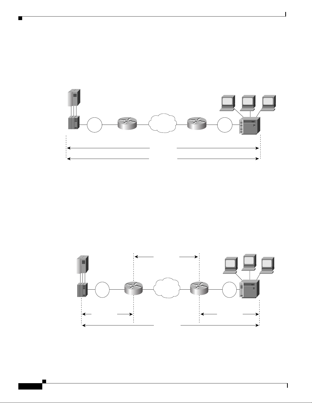
Figure 86 illustrates an LLC2 session in which a 37x5 on a LAN segment communicates with a 3x74 on
a different LAN segment separated via a wide-area backbone network. Frames are transported between
Router A and Router B by means of DLSw+. Howe v er , the LLC2 session b etween the 37x5 and the 3x74
is still end-to-end; that is, every frame generated by the 37x5 traverses the backbone network to the 3x74,
and the 3x74, on receipt of the frame, acknowledges it.
Figure 86 LLC2 Session Without Local Acknowledgment
Router B
Token
Ring
3x74
S1106a
37x5
Token
Ring
Router A
WAN
LLC2 session
On backbone networks consisting of slow serial lin ks, the T1 timer on end hosts could e xpire before th e
frames reach the remote hosts, causing the end host to resend . Resending results in duplicate frames
reaching the remote host at the same time as the first frame reaches the remote host. Such frame
duplication breaks the LLC2 protocol, resulting in the loss of sessions between the two IBM machines.
One way to solve this time delay is to increase the timeout value on the end nodes to account for the
maximum transit time between the two end machines. However, in networks consisting of hundreds or
even thousands of nodes, every machine would need to be reconfigured with new values. With local
acknowledgment for LLC2 enabled, the LLC2 session between the two end nodes would not be not
end-to-end, but instead, would terminate at two local routers. Figure 87 shows the LLC2 session with
the 37x5 ending at Router A and the LLC2 session with the 3x74 end ing at Router B. Both Rou ter A and
Router B execute the full LLC2 protocol as part of local acknowledgment for LLC2.
Figure 87 LLC2 Session with Local Acknowledgment
TCP session
7x5
Token
Ring
Router A
LLC2 session LLC2 session
WAN
Router B
SNA session
Token
Ring
3x74
S1107a
With local ackno wledgment for LLC2 enabled in both routers, Router A ackno wledges frames received
from the 37x5. The 37x5 still operates as if the acknowledgments it receives are from the 3x74. Router
A looks like the 3x74 to the 37x5. Similarly, Router B acknowledges frames received from the 3x74. The
Cisco IOS Bridging and IBM Networking Configuration Guide
BC-208
78-11737-02
Page 9

Overview of IBM Networking
3x74 operates as if the acknowledgments it receives are from the 37x5. Router B looks like the 3x74 to
37x5. Because the frames do not have to travel the WAN backbone networks to be acknowledged, but
are locally acknowledged by routers, the end machines do not time out, resulting in no loss of sessions.
Enabling local acknowledgment for LLC2 has the following advantages:
DLSw+
• Local acknowledgment for LLC2 solves the T1 timer problem without having to change any
configuration on the end nodes. The end nodes are unaware that the sessions are locally
acknowledged. In networks consisting of hun dreds or even thousands of machines, this is a definite
advantage. All the frames acknowledged by the Cisco IOS software appear to the end hosts to be
coming from the remote IBM machine. In fact, by looking at a trace from a protocol analyzer, one
cannot say whether a frame was acknowl edged by the local router or b y a remote IBM machine. The
MAC addresses and the RIFs generated by the Cisco IOS software are identical to those generated
by the remote IBM machine. The only way to f ind out whether a session is locall y acknowledged is
to use either a show local-ack command or a show source-bridge command on the router.
• All the supervisory (RR, RNR, REJ) frames that are locally acknowledged go no farther than the
router. Without local acknowledgment for LLC2, every frame traverses the backbone. With local
acknowledgment, only data (I-frames) traverse the backbone, resulting in less traffic on the
backbone network. For installations in which customers pay for the amount of traffic passing
through the backbone, this could be a de finite cost-saving measure. A simple protocol exists
between the two peers to bring up or down a TCP session.
Notes on Using LLC2 Local Acknowledgment
LLC2 local acknowledgment is enabled with TCP and DLSw+ Lite remote peers.
If the LLC2 session between the loca l host and the router terminates in either router, the other will be
informed to terminate its connection to its local host.
If the TCP queue length of the connection between the two routers reaches the high-water mark, the
routers sends Receiver -Not- Ready (RNR) messages to the local hosts un til the queue limit is r educed to
below this limit. It is possible, ho we ver, to prevent the RNR messages from being sent by using the dlsw
llc2 nornr command.
The configuration of the LLC2 parameters for the local Token Ring interfaces can affect overall
performance. Refer to the chapter “Configuring LLC2 and SDLC Parameters” in this manual for more
details about fine-tuning your network through the LLC2 parameters.
The routers at each end of the LLC2 session execute the full LLC2 protocol, which could result in some
overhead. The decision to use local acknowledgment for LLC2 should be based on the speed of the
backbone network in relation to the Token Ring speed. For LAN segments separated by slo w-speed serial
links (for example, 56 kbps), the T1 timer probl em could occur more frequently. In such cases, it might
be wise to turn on local acknowledgment for LLC2. For LAN segments separated by a T1, backbone
delays will be minimal; in such cases, FST or direct should be considered. Speed mismatch between t he
LAN segments and the backbone network is one criterion to help you decide to use local
acknowledgment for LLC2.
There are some situations (such as the receiving host failing between the time the sending host sends
data and the time the receiving host receives it), in which the sending host would determine, at the LLC2
layer, that data was recei ved when it actually was not. This error occurs because the router ackno wledges
that it received data from the sending host before it determines that the receiving host can actually
receive the data. But because both NetBIOS and SNA have error recovery in situations where an end
device goes down, these higher-level protocols will resend any missing or lost data. Because these
transaction request/confirmation prot ocols exist above LLC2, they are not affected by tight timers, as is
LLC2. They also are transparent to local acknowledgment.
78-11737-02
Cisco IOS Bridging and IBM Networking Configuration Guide
BC-209
Page 10

DLSw+
If you are using NetBIOS applications, note that there are two NetBIOS timers—one at the link level
and one at the next high er lev el. Local acknow ledgment for LLC2 is designed to solv e link timeouts only .
If you are experiencing NetBIOS session timeouts, you have two options:
• Experiment with increasing your NetBIOS timers and decreasing your maximum NetBIOS frame
size.
• Avoid using NetBIOS applications on slow serial lines.
Note By default, the Cisco IOS software translates Token Ring LLC2 to Ethernet 802.3 LLC2. To
configure the router to translat e Token Ring LLC2 frames into Ethernet 0x80d5 format frames, refer
to the section “Enable T ok en Ring LLC2-to-Ethernet Con v ersion” in the “Conf iguring Source-Ro ute
Bridging” chapter of the Cisco IOS Bridging and IBM Networking Command Reference (Volume 1
of 2).
DLSw+ Support for Other SNA Features
DLSw+ can be used as a transport for SNA features such as LAN Network Manager (LNM), DSPU, SNA
service point, and SNA Switching Services (SNASw) through a Cisco IOS feature called virtual
data-link control (VDLC).
LNM over DLSw+ allows DLSw+ to be used i n Token Ring networks that are managed by IBM’s LNM
software. Using this feature, LNM can be used to manage Token Ring LANs, control access units, and
Token Ring attached devices over a DLSw+ network. All management functions continue to operate as
they would in a source-route bridged network or an RSRB network.
Overview of IBM Networking
DSPU over DLSw+ allows the Cisco DSPU feature to operate in conjunction with DLSw+ in the same
router. DLSw+ can be used either upstream (toward the mainframe) or downstream (away from the
mainframe) of DSPU. DSPU concentration consolidates the appearance of multiple physical units (PUs)
into a single PU appearance to VTAM, minimizing memory and cycles in central site resources (VTAM,
NCP, and routers) and speeding network startup.
SNA service point over DLSw+ allows the Cisco SNA service point feature to be used in conjunction
with DLSw+ in the same router. Using this feature, SNA service point can be configured in remote
routers, and DLSw+ can provide the path for the remote service point PU to communicate with NetView.
This allows full management visibility of resources from a NetView 390 console, while concurrently
offering the value-added features of DLSw+ in an SNA network.
SNASw over DLSw+ allows the Cisco APPN Branch Extender functionality to be used in conjunction
with DLSw+ in the same router. With this feature, DLSw+ can be used to access SNASw in the data
center. DLSw+ can also be used as a transport SNASw upstream connectivity, providing nondisruptive
recovery from failures. The DLSw+ network can appear as a connection network to the SNASw nodes.
Using DLSw+ as a transport for other Cisco IOS SNA features requires a feature called VDLC. Cisco
IOS data-link users (such as LNM, DSPU, SNA service point, and SNASw) write to a virtual data-link
control interface. DLSw+ then reads from this interface an d sends out the traffic. Similarly, DLSw+ can
receive traffic destined for one of these Data Link Users and write it to the virtual data-link control
interface, from which the appropriate Data Link User will read it.
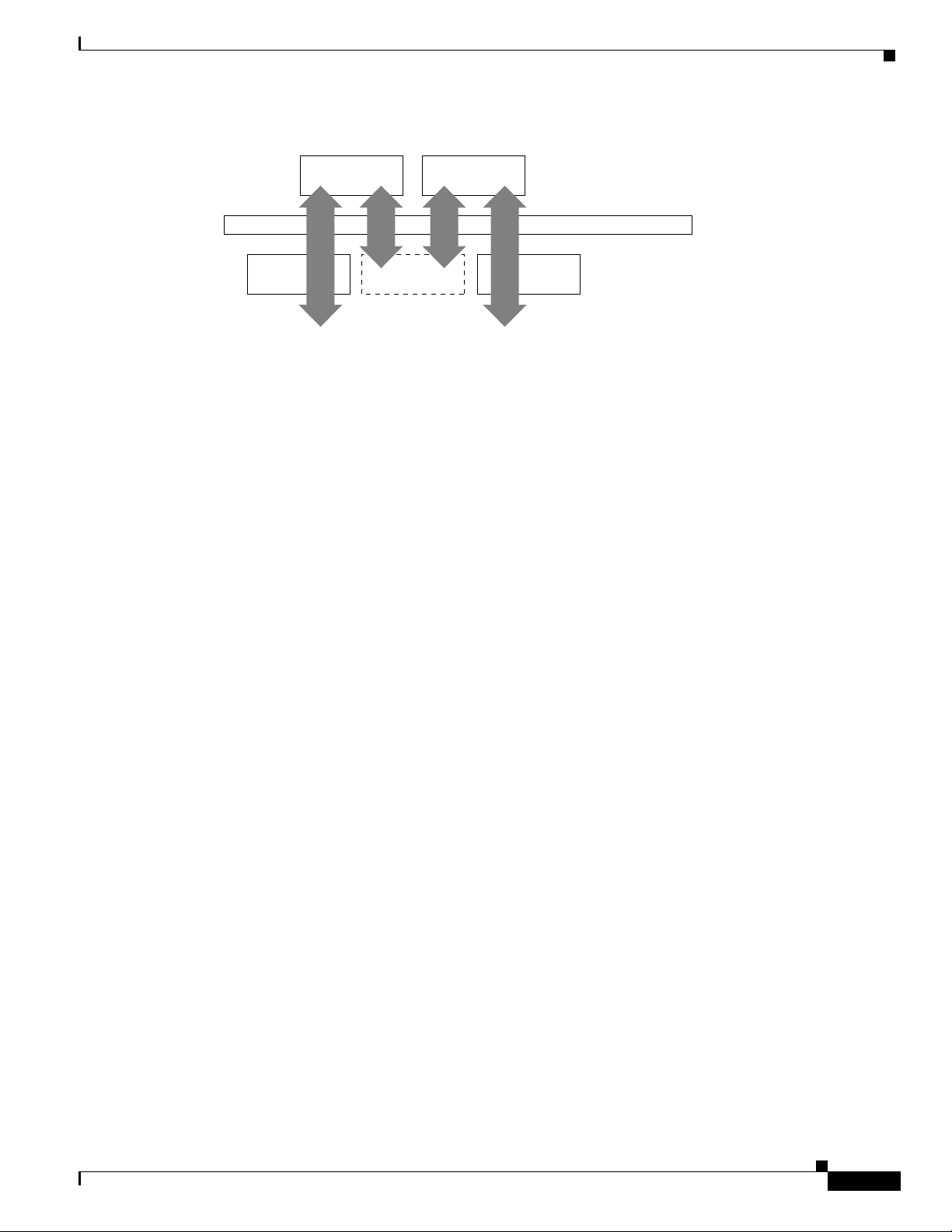
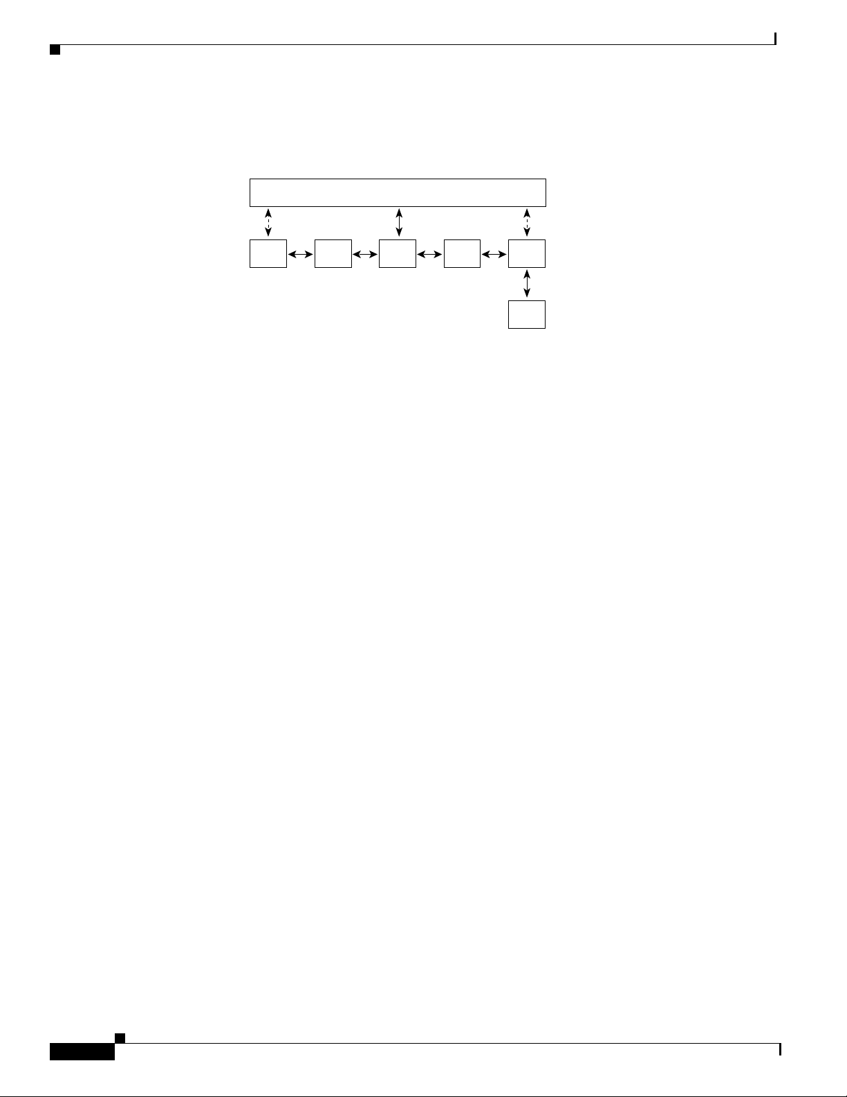
In Figure 88, SNASw and DLSw+ use Token Ring and Ethernet, respectively, as “real” data-link
controls, and use virtual data-link control to communicate between themselves. When one of the
high-layer protocols passes data to the virtual data-link control, the virtual data-link control must pass
it to a higher-layer protocol; nothing leaves the virtual data-link control without going through a
data-link user.
BC-210
Cisco IOS Bridging and IBM Networking Configuration Guide
78-11737-02
Page 11
Overview of IBM Networking
5
ls
Figure 88 VDLC Interaction with Higher-Layer Protocols
STUN and BSTUN
Token
Ring
The higher-layer protocols make no distinction between the VDLC and any other data-link control, but
they do identify the VDLC as a destin ation . In the e xample sho wn in , SNASw has two ports: a physical
port for Token Ring and a logical (virtual) port for the VDLC. In the case of the SNASw VDLC port,
when you define the SNASw VDLC port, you can also specify the MAC address assigned to it. That
means data going from DLSw+ to SNASw b y way of the VDLC is di rected to th e VDLC MAC address.
The type of higher-layer protocol you use determines how the VDLC MAC address is assigned.
STUN and BSTUN
The Cisco IOS software supports serial tunnel (STUN) and block serial tunnel (BSTUN). Our BSTUN
implementation enhances Cisco 2500, 4000, 4500, 4700, 7200 series routers to support devices that use
the Binary Synchronous Communication (Bisync) data-link protocol and asynchronous security
protocols that include Adplex, ADT Security Systems, Inc., Diebold, and asynchronous generic traffic.
BSTUN implementation is also supported on the 4T network interf ace module (NIM) on the Cisco 4000
and 4500 series routers. Our support of the bisync protocol enables enterprises to transport Bisync traffic
and SNA multiprotocol traffic over the same network.
This section contains the following topics:
• STUN Networks, page 211
SNASw
VDLC
DLSw+ Data-link users
CLSI
Ethernet
Data-link contro
1909
• STUN Features, page 212
• BSTUN Networks, page 215
• BSTUN Features, page 215
STUN Networks
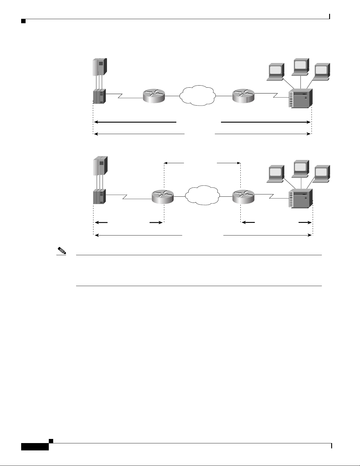
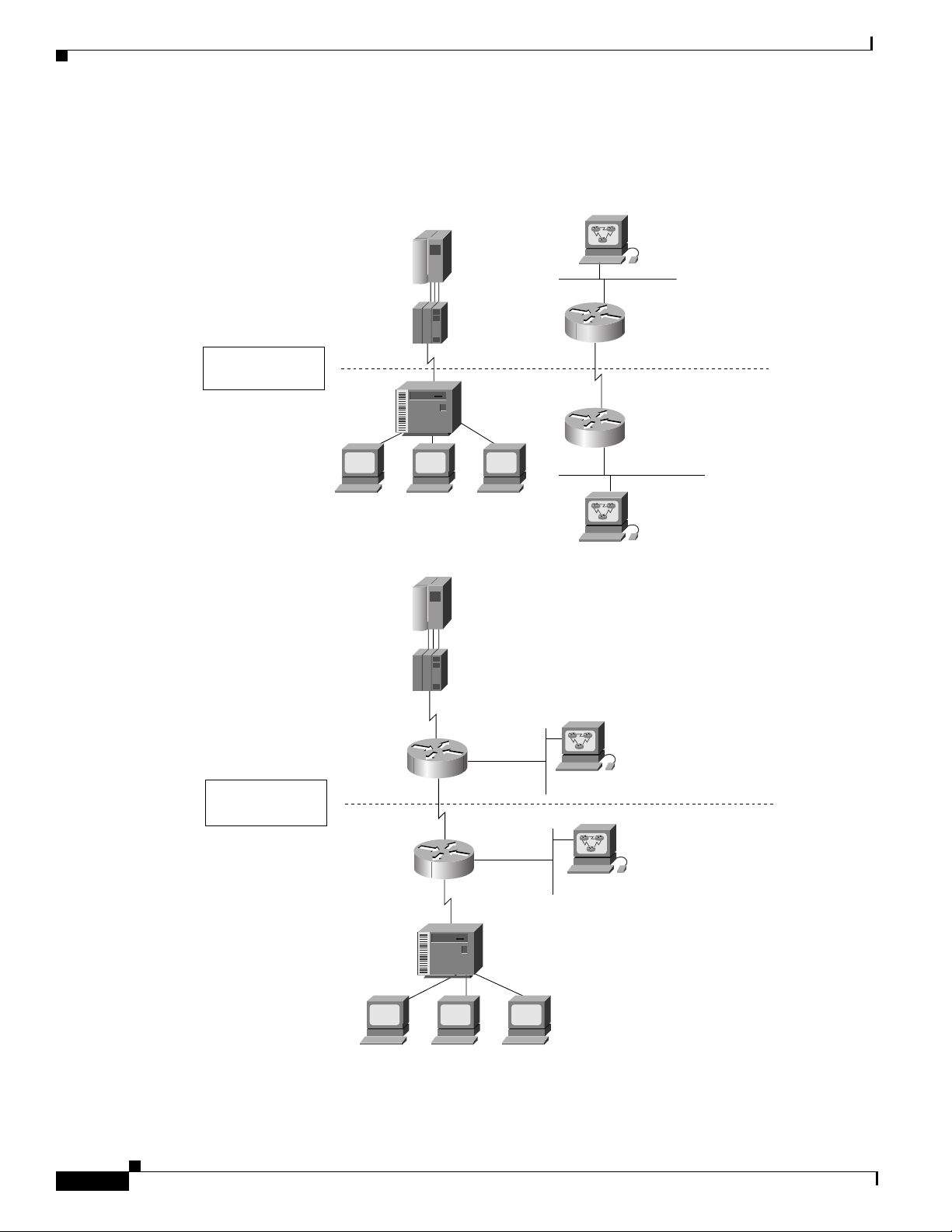
STUN operates in two modes: passthrough and local acknowledgment. Figure 89 shows the difference
between passthrough mode and local acknowledgment mode.
The upper half of Figure 89 shows STUN configured in passthrough mode. In passthrough mode, the
routers act as a wire and the SDLC session remains between the end stations. In this mode, STUN
provides a straight passthrough of all SDLC traffic, including control frames.
The lower half of Figure 89 shows STUN configured in local acknowledgment mode. In local
acknowledgment mode, the routers terminate the SDLC sessions and send only data across the WAN.
Control frames no longer travel the WAN backbone networks.
78-11737-02
Cisco IOS Bridging and IBM Networking Configuration Guide
BC-211
Page 12
STUN and BSTUN
I
SNA session
Overview of IBM Networking
Figure 89 Comparison of STUN in Passthrough Mode and Local Acknowledgment Mode
37x5
BM 1
WAN
3x74
IBM1
SDLC session
SNA session
TCP session
37x5
IBM 1
SDLC session
Note To enable STUN local acknowledgment, you first enable the routers for STUN and configure them
WAN
IBM 2
SDLC session
to appear on the network as primary or secondary SDLC nodes. TCP/IP encapsulation must be
enabled. The Cisco STUN local acknowledgment feature also provides priority queueing for
TCP-encapsulated frames.
3x74
S2839
STUN Features
The Cisco STUN implementation provides the following features:
Cisco IOS Bridging and IBM Networking Configuration Guide
BC-212
• Encapsulates SDLC frames in either the Transmission Control Protocol/Internet Protocol (TCP/IP)
or the HDLC protocol.
• Allows two devices using SDLC- or HDLC-compliant protocols that are normally connected by a
direct serial link to be connected through one or more Cisco routers, reducing leased-line costs.
When you replace direct serial links with routers, serial frames can be propagated over arbitrary
media and topologies to another router with a STUN link to an appropriate endpoint. The
intervening network is not restricted to STUN traffic, but rather, is multiprotocol. For example,
instead of running parallel backbones for DECnet and SNA/SDLC traffic, this traffic now can be
integrated into an enterprise backbone network.
• Supports local acknowledgment for direct Frame Relay connectivity between routers, without
requiring TCP/IP.
78-11737-02
Page 13

Overview of IBM Networking
STUN and BSTUN
• Allows networks with IBM mainframes and communications controllers to share data using Cisco
routers and existing network links. As an SDLC function, STUN fully supports the IBM SNA and
allows IBM SDLC frames to be sent across the network media and shared serial links. illustrates a
typical network configuration without STUN and the same network configured with STUN.
• Encapsulates SDLC frame traffic packets and routes them ov er an y of the support ed netw ork media
(serial, FDDI, Ethernet, and Token Ring, X.25, SMDS, and T1/T3) using TCP/IP encapsulation.
Because TCP/IP encapsulation is used, you can use any of the Cisco routing protocols to route the
packets.
• Copies frames to destinations based on address. STUN in passthrough mode does not modify the
frames in any way or participate in SDLC windowing or resending; these functions are left to the
communicating hosts. However, STUN in local acknowledgment mode does participate in SDLC
windowing and resending through local termination of the SDLC session.
• Ensures reliable sending of data across serial media ha ving minimal or predictable time del ays. With
the advent of STUN and WAN backbones, serial links now can be separated by wide geographic
distances spanning countries and continents. As a result, these serial links have time delays that are
longer than SDLC allows for bidirectional communication between hosts. The STUN local
acknowledgment feature addresses the problems of unpredictable time delays, multiple resending,
or loss of sessions.
• Allows for configuration of redundant links to provide transport paths if part of the network goes
down.
78-11737-02
Cisco IOS Bridging and IBM Networking Configuration Guide
BC-213
Page 14
STUN and BSTUN
Overview of IBM Networking
Figure 90 shows the difference between an IBM network with STUN and one without STUN.
Figure 90 IBM Network Configuration without STUN and with STUN
Without
STUN
IBM mainframe
37x5
3x74
IBM 3x78 terminals
IBM mainframe
Workstation
Ethernet
Local
site
T1 serial link
Remote
site
Ethernet
Workstation
With
STUN
37x5
Ethernet
T1 serial link
Ethernet
3x74
IBM 3x78 terminals
Workstation
Local
site
Remote
site
Workstation
S2075
BC-214
Cisco IOS Bridging and IBM Networking Configuration Guide
78-11737-02
Page 15

Overview of IBM Networking
BSTUN Networks
The Bisync feature enables your Cisco 2500, 3600, 4000, 45 00, 4700, and 7200 series router to support
devices that use the Bisync data-link protocol. Th is protoco l enables ente rprises to tran sport Bisync
traffic over the same network that supports their SNA and multiprotocol traffic, eliminating the need for
separate Bisync facilities.
At the access router, traff ic from the attached Bisync device is encapsulated in IP. The Bisync traffic can
then be routed across arbitrary media to the host site where another router supporting Bisync will remov e
the IP encapsulation headers and present the Bisync traffic to the Bisync host or controller over a serial
connection. HDLC can be used as an alternative encapsulation method for point-to-point links.
BSTUN Features
The Cisco implementation of BSTUN provides the following features:
• Encapsulates Bisync, Adplex, ADT Security Systems, Inc., Diebold, asynchronous generic, and
LLC2 and SDLC Parameters
Monitor Dynamics Inc., traffic for tran sfer over router l inks. The tunneling of asynchronous security
protocols (ASP) feature enables your Cisco 2500, 3600, 4000, 4 500, or 7200 series router to support
devices that use the following asynchronous security protocols:
–
adplex
–
adt-poll-select
–
adt-vari-poll
–
diebold
–
async-generic
–
mdi
• Provides a tunnel mechanism for BSTUN over Frame Relay, without using TCP/IP encapsul ation.
• Supports Bisync devices and host applications without modification.
• Uses standard synchronous serial interfaces on Cisco 2500 series and the 4T network interface
module (NIM) on the Cisco 4000 series and Cisco 4500 series.
• Supports point-to-point, multidrop, and virtual multidrop configurations.
Note The async-generic item is not a protocol name. It is a command keyword used to indicate generic
support of other asynchronous security protocols that are not explicitly supported.
LLC2 and SDLC Parameters
The LLC2 and SDLC protocols provide data link layer support for higher-layer network protocols and
features such as SDLC Logical Link Control (SDLLC) and RSRB with local acknowledgment. The
features that are affected by LLC2 parameter settings are listed in the “The Cisco Implementation of
LLC2” section on page 216. The features that require SDLC configuration and use SDLC parameters are
listed in the “The Cisco Implementation of SD LC” section on page 21 7.
LLC2 and SDLC package data in frames. LLC2 and SDLC stations require acknowledgments from
receiving stations after a set amount of frames have been sent before sending further data. The tasks
described in this chapter modify default settings regarding the control field of the data frames. By
78-11737-02
Cisco IOS Bridging and IBM Networking Configuration Guide
BC-215
Page 16

LLC2 and SDLC Parameters
modifying the control field parameters, you can determine the number of acknowledgments sent for
frames received and the leve l of polli ng used to determine av ailable stations. In this manner, you can set
the amount of resources used for frame checking and optimize the network load.
SDLC is used as the primary SNA link-layer protocol for WAN links. SDLC defines two types of
network nodes: primary and secondary. Primary nodes poll secondary nodes in a predetermined order.
Secondary nodes then send any outgoing data. When configured as primary and secondary nodes, our
routers are established as SDLC stations.
The Cisco Implementation of LLC2
The Cisco LLC2 implementation supports the following features:
• Local acknowledgment for RSRB
This feature is used in our implementation of RSRB as described in the chapter “Configuring
Source-Route Bridging.”
Because LANs are now connected through RSRB and WAN backbones, the delays that occur are
longer than LLC2 allows for bidirectional communication between hosts. Our local
acknowledgment feature addresses the problem of delays, resending, and loss of user sessions.
Overview of IBM Networking
• IBM LNM support
Routers using 4- or 16-Mbps Token Ring interfaces configured for SRB support Lan Network
Manager (LNM) and provide all IBM bridge program functions. With LNM, a router appears as an
IBM source-route bridge, and can manage or monitor any connected Token Ring interface.
LNM support is described in the chapter “Configuring Source-Route Bridging.”
• SDLLC media translation
The SDLLC feature provides media translation between the serial lines running SDLC and Token
Rings running LLC2. SDLLC consolidates the IBM SNA networks running SDLC into a
LAN-based, multiprotocol, multimedia backbone network.
SDLLC is described in the chapter “Co nfiguring IBM Network Media Translation.”
• ISO Connection-Mode Network Service (CMNS)
The Cisco CMNS implementation runs X.25 packets over LLC2 so that X.25 can be extended to
Ethernet, FDDI, and Token Ring media.
BC-216
Cisco IOS Bridging and IBM Networking Configuration Guide
78-11737-02
Page 17

Overview of IBM Networking
The Cisco Implementation of SDLC
The Cisco SDLC implementation supports the following features:
• Frame Relay Access Support (FRAS)
With FRAS, a router functions as a Frame Relay Access Device (FRAD) for SDLC, Token Ring,
and Ethernet-attached devices over a Frame Relay Boundary Network Node (BNN) link.
Frame Relay access support is described i n the chapter “Configuring SNA Frame Relay Access
Support.”
• SDLLC media translation
The SDLLC feature provides media translation between the serial lines running SDLC and Token
Rings running LLC2. SDLLC consolidates the IBM SNA networks running SDLC into a
LAN-based, multiprotocol, multimedia backbone network.
SDLLC is described in the chapter “Co nfiguring IBM Network Media Translation.”
• SDLC local acknowledgment
SDLC local acknowledgment is used with SDLC STUN. TCP/IP must be enabled. With local
acknowledgment, STUN SDLC connection s can be te rminated locally at the rout er, eliminating the
need for acknowledgments to be sent across a WAN.
SDLC local acknowledgment is described in the section “Establish the Frame Encapsulation
Method” in the chapter “Configuring STUN and BSTUN.”
IBM Network Media Translation
IBM Network Media Translation
The Cisco IOS software includes the following media translation features that enable network
communications across heterogeneous media:
• SDLLC media translation enables a device on a T oken Ring to communicate with a de vice on a serial
link.
• QLLC conversion enables an IBM device to communicate with an X.25 network without having to
install the X.25 software on local IBM equipment.
SDLLC is a Cisco Systems proprietary software feature that enables a device on a Token Ring to
communicate with a device on a serial link by translating between LLC2 and SDLC at the link layer.
SNA uses SDLC and LLC2 as link layer protocols to provide a reliable connection. The translation
function between these industry-standard protocols takes place in the proprietary Cisco software.
This section contains a brief overview of IBM Network Media Translation:
• SDLLC Media Translation Features, page 218
• QLLC Conversion, page 220
• The Cisco Implementation of QLLC Conversion, page 221
• Comparing QLLC Conversion to SDLLC, page 222
• Other Implementation Considerations, page 223
78-11737-02
Cisco IOS Bridging and IBM Networking Configuration Guide
BC-217
Page 18
IBM Network Media Translation
Figure 91 illustrates how SDLLC provides data link layer support for SNA communication.
Figure 91 SNA Data Link Layer Support
Overview of IBM Networking
Upper layers
Data link layer
SDLC SDLLC LLC LNX QLLC
SDLLC Media Translation Features
The SDLLC feature allows a PU 4, PU 2.1, or PU 2 to communicate with a PU 2 SDLC device as follows:
• SDLLC with direct connection—A 37x5 front-end pro cessor (FEP) on a Token Ring and the 3x74
cluster controller connected to a serial line are each connected to an interface on the same router
configured with SDLLC.
• SDLLC with RSRB—A 37x5 FEP on a Token Ring and a 3x74 cluster controller connected to a
serial line are connected to different routers. Only the device to which the 3x74 is connected is
configured with SDLLC. The routers communicate via RSRB using direct encapsulation, RSRB
over an FST connection, or RSRB over a TCP connection.
• SDLLC with RSRB and local acknowledgment—A 37x5 FEP on a Token Ring and a 3x74 cluster
controller connected to a serial line are connected to different routers. Only the devi ce to wh ich the
3x74 is connected is configured with SDLLC. The routers communicate via RSRB over a TCP
connection that has local acknowledgment enabled.
SNA
X.25
S3028
In all these topologies, each IBM end node (the FEP and cluster controller) has no indication that its
counterpart is connected to a different medium running a different protocol. The 37x5 FEP responds as
if the 3x74 cluster controller were communicating over a Token Ring, whereas the 3x74 responds as
though the 37x5 FEP were communicating over a serial line. That is, the SDLLC software makes
translation between the two m edia tran sparent to the end no des.
Virtual Token Ring Concept
Central to the Cisco SDLLC feature is the concept of a virtual Token Ring device residing on a virtual
T o ke n Ring. Because t he Token Ring device expect s the node with which it is commu nicating al so to be
on a Token Ring, each SDLLC device on a serial line must be assigned an SDLLC virtual Token Ring
address (SDLLC VTRA). Like real Token Ring addresses, SDLLC VTRAs must be unique across the
network.
In addition to the SDLLC VTRA, an SDLLC virtual ring number must be assigned to each SDLLC
device on a serial line. (The SDLLC virtual rin g number dif fers from the virtual ring grou p numbers that
are used to configure RSRB and multiport bridging.)
Cisco IOS Bridging and IBM Networking Configuration Guide
BC-218
78-11737-02
Page 19

Overview of IBM Networking
As part of its virtual telecommunications access method (VTAM) configuration, the IBM node on the
Token Ring has knowledge of the SDLLC VTRA of the serial device with which it communicates. The
SDLC VTRA and the SDLLC virtual ring number are a part of the SDLLC co nfigu ration for the ro uter’s
serial interface. When the Token Ring host sends out explorer packets with the SDLLC VTRA as the
destination address in the MAC headers, the router configured with that SDLLC VTRA intercepts the
frame, fills in the SDLLC virtual ring number address and the bridge number in the RIF, then sends the
response back to the Token Ring host. A route is then established between the Token Ring host and the
router. After the Cisco IOS software performs the appropriate frame conversion, the system uses this
route to forward frames to the serial device.
Resolving Differences in LLC2 and SDLC Frame Size
IBM nodes on Token Ring media normally use frame sizes greater than 1 KB, whereas the IBM nodes
on serial lines normally limit frame sizes to 265 or 521 bytes. To reduce traffic on backbone networks
and provide better performance, Token Ring nodes should send frames that are as large as possible. As
part of the SDLLC configuration on the serial interf ace, the largest frame size the two media can support
should be selected. The Cisco IOS software can fragment the frames it receives from the Token Ring
device before forwarding them to the SDLC device, but it does not assemble the frames it receives from
the serial device before forwarding them to the Token Ring device.
IBM Network Media Translation
Maintaining a Dynamic RIF Cache
SDLLC maintains a dynamic RIF cache and caches the entire RIF; that is, the RIF from the source station
to destination station. The cached entry is based on the best path at the time the session begins. SDLLC
uses the RIF cache to maintain the LLC2 session between the router and the host FEP. SDLLC does not
age these RIF entries. Instead, SDLLC places an entry in the RIF cache for a session when the session
begins and flushes the cache when the session terminates. You cannot flush the se RIFs because if you
flush the RIF entries randomly, the Cisco IOS software cannot maintain the LLC2 session to the host
FEP.
Other Considerations
The following are additional facts regarding SDLC and SDLLC:
• As part of the Cisco SDLC implementation, only modulus 8 Normal Response Mode (NRM)
sessions are maintained for the SDLC session.
• SDLC sessions are always locally acknowledged. LLC2 sessions can be optionally configured for
local acknowledgment.
• SDLLC does not apply to SNA subarea networks, such as 37x5 FEP-to-37x5 FEP communication.
• Parameters such as the maximum number of information frames (I-frames) outstanding before
acknowledgment, frequency of polls, and response time to poll frames can be modified per interface.
If local acknowledgment is not enabled, these parameters are modified on the SDLC interface. If
local acknowledgment is enabled, these parameters are modified on the Token Ring interface.
• Local acknowledgment only applies when the remote peer is defined for RSRB using IP
encapsulation over a TCP connection. If no local acknowledgment is used, the remote peer can be
defined for RSRB using direct encapsulation, RSRB using IP encapsulation over an FST connection,
or RSRB using IP encapsulation over a TCP connection.
78-11737-02
Cisco IOS Bridging and IBM Networking Configuration Guide
BC-219
Page 20

IBM Network Media Translation
S3029
QLLC Conversion
Qualified Logical Link Control (QLLC) is a data link protocol defined by IBM that allows SNA data to
be transported across X.25 networks. (Although IBM has defined other protocols for transporting SNA
traffic over an X.25 network, QLLC is the most widely used.) Figure 92 illustrates how QLLC
conversion provides data link layer support for SNA communication.
Figure 92 SNA Data Link Layer Support
Overview of IBM Networking
Upper layers
Data link layer
SDLC SDLLC LLC LNX QLLC
SNA
X.25
S3028
As shown in Figure 93, any devices in the SNA communi cation path that use X.25, whether end systems
or intermediate systems, require a QLLC implementation.
Figure 93 SNA Devices Running QLLC
Running QLLC Running QLLC
X.25 network
As shown in Figure 94, the QLLC conversion feature elimi nates the need to install the X.25 software on
local IBM equipment. A device attached locally to a Token Ring network can communicate through a
router running the QLLC Conversion feature with a remote device attached to an X.25 network using
QLLC. Typically, the locally attached device is an FEP, an AS 400, or a PS/2, and the remote device is
a terminal controller or a PS/2. In this case, only the remote device needs an X.25 interface and the FEP
can communicate with the terminal controller as if it were directly attached via a Token Ring network.
BC-220
Figure 94 Router Running QLLC Conversion Feature
X.25 network
More elaborate configurations are possible. The router that implements QLLC conversion need not be
on the same Token Ring network as the FEP. As shown in Figure 95, QLLC/LLC2 conversion is possible
even when an intermediate IP WAN exists between the router connected to the X.25 network and the
router connected to the Token Ring.
Cisco IOS Bridging and IBM Networking Configuration Guide
Running QLLC
Token
Ring
S3030
78-11737-02
Page 21

Overview of IBM Networking
S3031
3
Figure 95 QLLC Conversion Running on a Rout er wi th an Intermediate IP Network
X.25/QLLC session TCP session LLC2 session
IBM Network Media Translation
Running QLLC
X.25 network
Router A Router B
IP network
The Cisco Implementation of QLLC Conversion
SNA uses QLLC and X.25 as link layer protocols to provide a reliable connection. QLLC itself processes
QLLC control packets. In a Token Ring environment, SNA uses LLC to provide a reliable connection.
The LAN-to-X.25 (LNX) software provides a QLLC conversion function to translate between LLC and
QLLC.
Figure 96 shows the simplest QLLC conversion topology: a single Token Ring device (for example, a
37x5 FEP) communicates with a single remote X.25 device (in this case a 3x74 cluster controller). In
this example, a router connects the Token Ring network to the X.25 network.
Figure 96 QLLC Conversion Between a Single 37x5 and a Single 3x74
LLC2 session QLLC/X.25 session
T0
Router
S0
Virtual
ring
7x5
Token
Ring
Running RSRB
Token
Ring
X.25
32703x74
SNA session
1910
In Figure 96, each IBM end node has no indication that its counterpart is connected to a different
medium running a different protocol. The 37x5 FEP responds as if the 3x74 cluster controller were
communicating over a Token Ring, whereas the 3x74 responds as though the 37x5 FEP were
communicating over an X.25 network. This is accomplished by configuring the router’s X.25 interface
as a virtual Token Ring, so that the X.25 virtual circuit appears to the Token Ring device (and to the
router itself) as if it were a Token Ring to which the remote X.25 device is attached.
Also in this figure, the LLC2 connection extends from the 37x5 FEP across the Token Ring network to
the router. The QLLC/ X.2 5 session extends from the router across the X.25 network to the 3x74 cluster
controller. Only the SNA session extends across the Token Ring and X.25 networks to provide an
end-to-end connection from the 37x5 FEP to the 3x74 cluster controller.
As Figure 97 shows, a router need not directly connect the two IBM end nodes; instead, some type of
backbone WAN can connect them. Here, RSRB transports packets between Router A and Router B,
while Router B performs all conversion between the LLC2 and X.25 protocols. Only the router attached
to the serial line (Router B) needs to be configured for QLLC conversion. Both Router A and Router B
78-11737-02
are configured for normal RSRB.
Cisco IOS Bridging and IBM Networking Configuration Guide
BC-221
Page 22

IBM Network Media Translation
a
a
4
4
Figure 97 QLLC Conversion Between a Single 37x5 and Multiple 3x74s across an Arbitrary WAN
Overview of IBM Networking
Without local
cknowledgment
With local
cknowledgment
37x5
LLC2 session
Token
T0
Ring
LLC2 session
TCP session
VR1
Arbitrary
WAN
Router A Router B
QLLC/X.25 session
QLLC/X.25 session
S0
VR2
Virtual
ring
X.25
3270
3x7
3x7
51924
3270
How communication sessions are established over the communication link varies depending on whether
or not LLC2 local acknowledgment has been configured on Router A’s Token Ring interface. In both
cases, the SNA session extends end-to-end and the QLLC/X.25 session extends from Router B to the
3x74 cluster controller. If LLC2 local acknowledgment has not been configured, the LLC2 session
extends from the 37x5 FEP across the Token Ring network and the arbitrary WAN to Router B. In
contrast, when LLC2 local acknowledgment has been configured, the LLC2 session extends from the
37x5 FEP Router A, where it is locally terminated. A TCP session is then used across the arbitrary WAN
to Router B.
Comparing QLLC Conversion to SDLLC
Although the procedures you use to config ure QLLC are similar to those used to configure SDLLC, there
are structural and philosophical differences between the point-to-point links that SDLC uses and the
multiplexed virtual circuits that X.25 uses.
The most significant structural difference between QLLC conversion and SDLLC is the addressing. To
allow a device to use LLC2 to transfer data, both SDLLC and QLLC provide virtual MAC addresses. In
SDLLC, the actual MAC address is buil t by combining the defined virtual MA C (whose last byte is 0x00)
with the secondary address used on the SDLC link; in this way, SDLLC supports multidrop. In QLLC
conversion, multidrop is meaningless, so the virtual MAC address represents just one session and is
defined as part of the X.25 configuration. Because on e physical X .25 interface ca n support m any
simultaneous connections for many dif ferent remote de vices, you only need one physical link to th e X.25
network. The different connections on different virtual circuits all use the same physical link.
The most significant difference between QLLC conversion and SDLLC is the fact that a typical
SDLC/SDLLC operation uses a leased line. In SDLC, dial-up connections are possible, but the
maximum data rate is limited. In QLLC, both switched virtual circuits (SVCs) and permanent virtual
circuits (PVCs) are available, but the favored use is SVC. While the router maintains a permanent
connection to the X.25 network, a remote device can use each SVC for some bounded period of time and
then relinquish it for use by another device. Using a PVC is very much like using a leased line.
BC-222
Cisco IOS Bridging and IBM Networking Configuration Guide
78-11737-02
Page 23

Overview of IBM Networking
Table 3 shows how the QLLC commands correspond to the SDLLC commands.
Table 3 QLLC and SDLLC Command Comparison
QLLC Command Analogous SDLLC Command
qllc largest-packet sdllc ring-largest-frame, sdllc
qllc partner sdllc partner
qllc sap sdllc sap
qllc srb, x25 map qllc, x25 pvc qllc sdllc traddr
qllc xid sdllc xid
source-bridge qllc-local-ack source-bridge sdllc-local-ack
Other Implementation Considerations
Consider the following when implementing QLLC conversion:
• To use the QLLC conversion feature, a router must have a physical link to an X.25 public data
network (PDN). It must also have an SRB/RSRB path to an IBM FEP. This link could be a Token
Ring or Ethernet interface, or even FDDI, if RSRB is being used.
• QLLC conversion can run on any router with at least one serial interface configured for X.25
communication and at least one other interface configured for SRB or RSRB.
• QLLC conversion security depends upon access control in SRB/RSRB and X.25 and upon XID
validation.
SNA FRAS
sdlc-largest-frame
SNA FRAS
You can configure DLSw+ for QLLC connectivity, which enables the following scenarios:
• Remote LAN-attached devices (physical units) or SDLC-attached devices can access an FEP or an
AS/400 over an X.25 network.
• Remote X.25-attached SNA devices can access an FEP or an AS/400 over a Token Ring or over
SDLC.
For information on configuring DLSw+ for QLLC conversion, refer to the “Configuring DLSw+”
chapter.
You can configure DSPUs for QLLC. For more information on this configuration, refer to the
“Configuring DSPU and SNA Service Point” chapter.
Using Frame Relay Access Support (FRAS), the Cisco IOS software allows branch SNA devices to
connect directly to a central site front-end processor over a Frame Relay network. FRAS converts LAN
or Synchronous Data-Link Control (SDLC ) protocols to a Frame Relay form at understoo d by the
Network Control Program (NCP) that runs in an FEP. The Cisco IOS software and the NCP support two
frame formats:
• RFC 1490 routed format for LLC2, specified in the FRF.3 Agreement from the Frame Relay Forum
and known in NCP literature as Frame Relay Boundary Network Node (BNN) support. Support for
this feature requires NCP 7.1 or higher.
• RFC 1490 802.5 source-route bridged format, known in NCP literature as Frame Relay Boundary
Access Node (BAN) support. Support for this feature requires NCP 7.3 or higher.
78-11737-02
Cisco IOS Bridging and IBM Networking Configuration Guide
BC-223
Page 24

SNA FRAS
5
Management service point support in FRAS allows t he SNA network management app lication, NetV iew,
to manage Cisco routers over the Frame Relay network as if it were an SNA downstream PU.
FRAS provides dial backup over RSRB in case the Frame Relay network is down. While the backup
Public Switched Telephone Network (PSTN) is being used, the Frame Relay connection is tried
periodically. As soon as the Frame Relay network is up, it will be used.
This section contains a brief overview of SNA FRAS which is described in the following topics:
• RFC 1490 Routed Format for LLC2 (BNN), page 224
• RFC 1490 Bridged Format for LLC2 (BAN), page 225
RFC 1490 Routed Format for LLC2 (BNN)
RFC 1490 specifies a standard method of encapsulating multiprotocol traffic with data link (Level 2 of
the OSI model) framing. The encapsulation for SNA data is specified in the FRF.3 Agreement.
The Frame Relay encapsulation method is based on the RFC 1490 frame format for “user-defined”
protocols using Q.933 NLPID, as illustrated in Figure 98.
Overview of IBM Networking
Figure 98 Frame Relay Encapsulation Based on RFC 1490
DLCI
Q.922
address
Control
0x30
NLPID
Q.933
0x08
L2
Protocol ID
0x4c (802.2) 0x08
L3
Protocol ID
DSAP
SSAP
Control F
C
S
1911
Note The protocol ID for SNA subarea FID4 is 0x81. The protocol ID for SNA subarea FID2 is 0x82. The
protocol ID for APPN FID2 is 0x83.
FRAS allows the router acting as a FRAD to take advantage of the SNA BNN support for Frame Relay
provided by ACF/NCP 7.1 and OS/400 V2R3. Downstream PU 2.0 and PU 2.1 devices can be attached
to the router through SDLC, Token Ring, or Ethernet links. The router acting as a FRAD is connected to
the Network Control Program (NCP) or AS/400 through a public or private Frame Relay network, as
illustrated in Figure 99.
Figure 99 SNA BNN Support for Frame Relay
SDLC
Frame Relay
NCP
Token
Ring
S3218
BC-224
The frame format that communicates across the Frame Relay BNN link is defined in RFC 1490 for
routed SNA traffic. From the perspective of the SNA host (for example an NCP or AS/400), the Frame
Relay connection is defined as a switched resource similar to a T oken Ring BNN link. Because the frame
format does not include link addresses to allo w the NCP t o distingui sh among SNA devices on the same
Cisco IOS Bridging and IBM Networking Configuration Guide
78-11737-02
Page 25

Overview of IBM Networking
5
permanent virtual circuit, Cisco suppor ts SAP multiplexing, which allows you to configure unique LLC2
SAPs for each downstream SNA device so that they can share a single permanent virtual circuit to an
FEP.
The Cisco IOS software is responsible for terminating the local data-link control frames (such as SDLC
and T ok en Ring frames) and for modifying the data-link control frames to 8 02.2 compliant LLC frames.
The LLC provides a reliable connection-oriented link layer transp ort required by SNA. (For example,
802.2 LLC is used to provide link layer acknowledgment, sequencing, and flow control.)
The Cisco IOS software encapsulates these 802.2 LLC frames according to the RFC 1490 format for
SNA traffic. The frames are then forwarded to the SNA host on a Frame Relay PVC. In the reverse
direction, the software is responsible for de-encapsulating the data from the Frame Relay PVC, and for
generating and sending the appropriate local data-link control frames to the downstream devices.
RFC 1490 Bridged Format for LLC2 (BAN)
BAN provides functionality similar to BNN except that it uses a bridged frame format, as illustrated in
Figure 100.
SNA FRAS
Figure 100 RFC 149 0 Bridged Frame Format
Q.922 address
Control 0x03 pad 0x00
NLPID SNAP 0x80 OUI 00x0
OUI 0x80-C2 (bridged)
PID 0x00-09
pad 0x00 Frame control
Destination/source MAC (12 bytes)
DSAP SSAP
Control
SNA data
PCS
1912
Because it includes the MAC header information in every frame, BAN supports multiple SNA devices
sharing a single permanent virtual circuit without requiring SAP multiplexing. BAN also supports load
balancing across duplicate data-link connection ident ifiers to the same or different front -end pro cessor s
at the data center to enhance overall availability. BAN works for devices attached by either Token Ring
or Ethernet.
78-11737-02
Cisco IOS Bridging and IBM Networking Configuration Guide
BC-225
Page 26

NCIA
NCIA
Overview of IBM Networking
Native Client Interface Architecture (NCIA) is a new software architecture introduced by Cisco to make
accessing IBM SNA applications over routed internetworks more scalable and flexible. NCIA is a
component of the Cisco IOS software. The architecture is intended to combine the benefits of the nati v e
SNA interface at end stations and mainframes with those of TCP/IP across the network backbone.
NCIA extends the use of the TCP/IP protocol all the way t o the SNA end station. Because of the wide
range of media supported by TCP/IP, including dialup telephone lines f or remotely located users, NCIA
makes multiprotocol access to corporate backbone networks much more flexible for SNA users.
NCIA allows SNA end stations such as PCs or workstations to encapsulat e SN A traf f ic in TCP/IP, rather
than requiring the traff ic to tra v el thr ough rou ters. The f irst phase of NCIA (NCIA I), used Cisco RSRB
encapsulation. The current phase (NCIA Server) uses a new client/server model. NCIA Server is not
backward compatible to NCIA I.
This section contains a brief overview of NCIA:
• NCIA I, page 226
• NCIA Server, page 226
• Advantages of the Client/Server Model, page 228
NCIA I
NCIA Server
The Cisco NCIA server feature implements RFC 2114, Data Link Swit c h Cli ent Access Protocol. Using
the Cisco RSRB technolog y , NCIA I encaps ulates the Token Ring traffic inside IP datagrams passed ov er
a TCP connection between a router and a client. A virtual ring is created to allow the router to
interconnect any client. The virtual ring acts as a logical Token Ring in the router, so that all the Token
Rings connected to the router are treated as if they are all on the same Token Ring. The virtual ring is
called a ring group. The ring group number is used just like a physical ring number and shows up in any
route descriptors contained in packets being bridged. A ring group must be assigned a ring number that
is unique throughout the network.
An NCIA I client acts as both an RSRB router and an end station. It must have a “fake” ring number and
a “fake” bridge number so that it looks lik e an end station sitting on a real T oken Ring. The fake ring and
bridge numbers are visible to both the RSRB router and the NCIA client. The client must also have an
LLC2 so that it can handle the LLC2 sessions.
The NCIA Server feature extends the scalability of NCIA I, enhances its functionality, and provides
support for both the installed base of RSRB routers and the growing number of DLSw+ routers. The
NCIA Server feature includes the following enhancements:
• You do not need to configure a ring number on the client.
• You do not need to configure each client on the router.
• The MAC address can be dynamically assigned by the NCIA server running on the router.
BC-226
• SNA is directly on top of TCP/IP; LLC2 is no longer required at end station.
• A client is a true end station, not a router peer.
Cisco IOS Bridging and IBM Networking Configuration Guide
78-11737-02
Page 27

Overview of IBM Networking
51913
• The NCIA Server communicates with other components in router, such as RSRB, SNASw, DLSw+,
and DSPU.
• Supports both connect-in and connect-out.
• The NCIA client/server model is independent of the upstream implementation.
• It is an efficient protocol between client and server.
NCIA Client/Server Model
The NCIA Server feature uses a client/server model (see Figure 101), where the NCIA server is a
software module on a Cisco router and the NCIA client is a PC or workstation. The NCIA server
performs two major functions:
• Establishes TCP to NCIA Data Link Control (NDLC) sessions with clients for the purpose of
sending and receiving data.
• Uses the Cisco link services interface (CLSI) to communicate with other software modules in the
router, such as SNASw, DLSw+, and DSPU, and acts as the data intermediary between them and
NCIA clients. The NCIA server’s role as an intermediary is tran sparent t o the clien t.
NCIA
Figure 101 NCIA Server Client/Server Model
SNASw
LLC2
Ethernet Token Ring
DLSw+ DLSw local switch DSPU
NCIA server RSRB
TCP/IP TCP/IP
NDLC
SNA
NCIA client
NCIA Data Link Control (NDLC) is the protocol used between clients and servers. NDLC serves two
purposes:
• Establishes the peer connection
• Establishes the circuit between the client and the server
The peer session must be established before an end-to-end circuit can be set up. During the set up period
for the peer session, the MAC address representing a client is defined. The MAC address can be defined
by the client or by the server when the client does not have a MAC address.
The NCIA Server feature supports connect-in and connect-out (from the server’s perspective), but
connect-out is not supported if the client statio n does not listen for the inco ming connection. For a serv er
to connect-out, clients must connect to the server first. After registering itself by providing its own MAC
address, the client can then optionally disconnect from the server. When a server receives an explorer,
and its destination MAC address is registered, an NCIA server will connect to that client if it is not
connected. For NetBIOS explorers (addressed to functional address 0xC00000000080), the TCP session
must remain up so that the server can broadcast the explorers to the client. If the TCP session is down,
the server will not send the NetBIOS explorers to a client, even when the client is registered.
78-11737-02
Cisco IOS Bridging and IBM Networking Configuration Guide
BC-227
Page 28

NCIA
M
51914
After the peer session has been established, the NDLC protocol establishes the circuit between the client
and server. This circuit is used to transfer end-user data between the client and the server. Because the
client and its target station are not on the same transport, they cannot form a direct, end-to-end circuit.
Each client must form a circuit between the client and server, and the server must form another circuit
between the server and the target station. The server links those two circuits to form an end-to-end
circuit. The server acts as a mediator between the client and the target station so that packets can be
transferred between them.
In the NCIA server only peer keepalive is maintained. There is no keepalive at circuit level.
The NCIA server acts as a data-link provider, like Token Ring or Ethernet, in the router. It uses CLSI to
communicate with other software modules, just as other data-link providers do. The network
administrator configures the router to communicate with specific modules. For data-link users, such as
SNASw, DLSw+, and DSPU, the NCIA server can inte rface to them d irectly. For other data-link
providers, the NCIA server must go through a DLSw+ local peer to communicate with them. The
DLSw+ local peer passes packets back and forth among different data-link providers.
Advantages of the Client/Server Model
The client/server model used in the NCIA Server feature extends the scalabi lity of NCIA. In addit ion, it
provides support for both the install ed base of RSRB routers and the gro wing numb er of DLSw+ routers.
Overview of IBM Networking
Extended Scalability
The client/server model minimizes the number of central site RSRB or DLSw+ peer connections
required to support a large network of NCIA clients (see Figure 102). Rather than each client having a
peer connection to a central site router, the clients attach to an IP backbone through an NCIA server that,
in turn, has a single peer connection to a central site router. This scheme can greatly reduce the number
of central site peer connections required. For example, in a network with 1000 clients and 10 NCIA
servers, there would be only 10 central site peer connections. Note that there would still be 1000 LLC2
connections that must be locally acknowledged at the central site router, but this can easily be handled
in a single central site router. When the number of LLC2 connections (or the number of clients) is in the
tens of thousands, NCIA servers can take advantage of downstream PU concentration to minimize the
number of LLC2 connections that must be supported by the central site routers.
Figure 102 NCIA Server Provides Extended Scalability to Support Large Networks
ainframe
with FEP
RSRB
IP
backbone
RSRB
NCIA
server
Token
Ring
NCIA
client
Cisco IOS Bridging and IBM Networking Configuration Guide
BC-228
78-11737-02
Page 29

Overview of IBM Networking
M
Migration Support
ALPS
Using a client/server model allows the NCIA Server feature to be independent of the upstream
implementation, allowing it to be implemented in a network that is still using RSRB and in a DLSw+
network. It also greatly simplifies migration from RSRB to DLSw+, because it requires no changes at
the client. A single NCIA server can support either approach (but not both). As Figure 103 illustrates, a
central site router can support RSRB and DLSw+ concurrently, allowing a portion of the NCIA servers
to communicate using RSRB and another portion to communicate using DLSw+.
Figure 103 NCI A Server Provides Independence from the Upstream Network Implementation
Client
workstation
Token
Ring
DLSw+
NCIA server
ALPS
RSRB/DLSw+
IP
backbone
RSRB
NCIA server
51915
Router peers
ainframe
with FEP
Computing center
Token
Ring
Cisco
The Airline Product Set (ALPS) is a tunneling mechanism that transports airline protocol data across a
TCP/IP network to a mainframe. ALPS provides connectivity between agent set control units (ASCUs)
and a mainframe host that runs the airline reservation system.
Figure 104 shows the basic ALPS topology and the protocols implemente d in the feature. Three major
components provide the end-to-end transportation of airline protocol traffic across the network: the
P1024B Airline Control (ALC) or P1024C (UTS) protocol, the TCP/IP-based MATIP protocol
conversion, and the TCP/IP access to the mainframe.
Cisco IOS Bridging and IBM Networking Configuration Guide
78-11737-02
BC-229
Page 30

DSPU and SNA Service Point
S
S
a
Figure 104 ALPS Architecture
Mainframe with
irline reservation
system
Overview of IBM Networking
Remote
router
ASCUs running ALC or UT
25065
Network
management system
The Cisco ALPS feature provides an end-to-end solution for airlines and central reservation systems.The
ALPS feature is integrated in the Cisco IOS software and allows airlines to replace their existing
hardware and software with Cisco routers. For customers who already use Cisco routers, this feature
allows them to consolidate networking overhead and functionality.
DSPU and SNA Service Point
Downstream physical unit (DSPU) is a software feature that enables the router to function as a PU
concentrator for SNA PU type 2 nodes. PU concentration at the device simplifies the task of PU
definition at the upstream host while providing additional flexibility and mobility for downstream PU
devices.
The DSPU feature allows you to def ine do wnstream PU type 2 de vices in the Cisco IOS softw are. DSPU
reduces the complexity of host configuration by letting you replace multiple PU definitions that
represent each downstream device with one PU definition that represents the router.
Because you define the downstream PUs at the router rather than the host, you isolate the host from
changes in the downstream network topology. Therefore you can insert and remove downstream PUs
from the network without making any changes on the host.
The concentration of downstream PUs at the router also reduces network t raf f i c on the WAN by limiting
the number of sessions that must be established and maintained with the host. The termination of
downstream sessions at the router ensures that idle session traffic does not appear on the WAN.
Remote
router
ASCUs running ALC or UT
SNA service point support in the Cisco IOS software assumes that NetView or an equivalent product is
available at the SNA host. The user interacts with the network management feature in the router and at
the SNA host. In the Cisco IOS software, you can configure the host connection and show the status of
this connection. At the SNA host, you can use the NetView operator’s console to view alerts and to send
and receive Cisco syntax commands to the Cisco device.
BC-230
Cisco IOS Bridging and IBM Networking Configuration Guide
78-11737-02
Page 31

Overview of IBM Networking
w
U
Us
Figure 105 shows a router functioning as a DSPU concentrator.
Figure 105 Router Acting as a DSPU Concentrator
DSPU and SNA Service Point
LU
LU
PU 2 + 3 L
Token
Ring
PU 2 + 1 L
PU 2 + 2 LUs
S3223
Mainframe
ith 1 PU and
8 LUs defined
Token
Ring
RSRB
PU 2 PU 5
DSPU concentrator
supporting 4 PUs
and 8 LUs
Typically, a router establishes one or more upstream connections with one or more hosts and many
downstream connections with PU type 2 devices. From an SNA perspective, the router appears as a PU
type 2 device to the upstream host and assumes the role of a system services control point (SSCP)
appearing as a PU type 5 device to its downstream PUs.
The SSCP sessions established between the router and its upstream host are com pletely independen t of
the SSCP sessions established between the ro uter and its downstream PUs. SNA traffic is routed at a
logical unit (LU) level using a routing algorithm that maps downstream LUs onto upstream LUs.
Figure 106 illustrates the SNA perspective of DSPU.
Figure 106 SNA Perspective of DSPU
Upstream PU
(PU type 2)
LU routing algorithm
Downstream PU A
(PU type 5)
78-11737-02
Downstream PU B
(PU type 5)
Cisco IOS Bridging and IBM Networking Configuration Guide
S3224
BC-231
Page 32

SNA Switching Services
SNA Switching Services
Note SNA Switching Services functionality sup ersedes all functionalit y pre viously a vailable in the APPN
feature in the Cisco IOS software. SNASw configuration will not accept the previous APPN
configuration commands. Previous APPN users should use this chapter to configure APPN
functionality using the new SNASw commands.
SNASw provides an easier way to design and implement networks with SNA routing requirements.
Previously, this network design was accomplished using APPN with full network node (NN) support in
the Cisco router. This type of support provided the SNA routing functionality needed, but was
inconsistent with the trends in Enterpr ise networks today. The corporate intranet is replacing the SNA
WAN. Enterprises are replacing their traditional SNA network with an IP infrastructure that supports
traffic from a v ariety of clients, usi ng a variety of proto cols, requiring access to applications on a v ariety
of platforms, including SNA applications on Enterprise servers.
While SNA routing is still required when multiple servers must be accessed, the number of nodes
required to perform this function is decreasing as the IP infrastructure grows and as the amount of native
SNA traffic in the network decreases.
Overview of IBM Networking
SNASw enables an enterprise to develop their IP infrastructure, while meeting SNA routing
requirements.
The number of NNs in the network and the amount of broadcast traffic are reduced. Configuration is
simplified, and SNA data traffic can be transported within the IP infrastructure. The following features
provide this functionality:
• HPR Capable SNA Routing Services, page 234
• Branch Extender, page 234
• Enterprise Extender (HPR/IP), page 235
• Usability Features, page 236
• Management Enhancements, page 237
• LAN and IP-Focused Connection Types, page 238
Benefits of SNASw
SNASw provides the following benefits:
• Scalable APPN Networks, page 233
• IP Infrastructure Support, page 233
• Reduced Configuration Requirements, page 233
• Network Design Simplicity, page 233
• Improved Availabilit y, page 233
BC-232
• Increased Management Capabi lities, page 233
• Architectural Compliance, page 233
Cisco IOS Bridging and IBM Networking Configuration Guide
78-11737-02
Page 33

Overview of IBM Networking
Scalable APPN Networks
With the Branch Extender (BEX) function, the number of network nodes and the amount of broadcast
traffic are reduced.
IP Infrastructure Support
Limiting SNASw r outers to t he data center and u sing the BEX functi on eliminates SNA broadcasts from
the IP network. Wit h Enterprise Extender (EE) , SNA traffic is routed using the IP routing infrastructure
while maintaining end-to-end SNA services.
Reduced Configuration Requirements
By eliminating NNs and using the BEX function, conf iguration tasks are minimized. Additionally, Cisco
has enhanced its auto-configuration capability to eliminate previously required commands.
Benefits of SNASw
Network Design Simplicity
By placing all SNA routers in the data center, few SNA routers are required, and they can be easily
configured using virtually identical configurations.
Improved Availability
By adding Cisco-unique capabilities to connect-out and distribute traff ic across multiple ports, access to
resources is improved and traffic can be distributed across multiple ports. Additionally, by supporting
the newest HPR Adaptive Rate-Based (ARB) flow control algorithm, bandwidth management for SNA
traffic is improved.
Increased Management Capabilities
Two new traces, interprocess and data-link, provide an easier way to view SNASw activity. The APPN
Trap MIB allows the user to notify the operator in event of a debilitating problem. Console message
archiving provides better tracking of network activity. The ability to format traces in a format so that
they are readable by oth er management products simplify network management because results are more
readily available.
Architectural Compliance
78-11737-02
Even though SNASw is easier t o use and SNASw networks are easier to design, SN ASw in terfaces wit h
SNA implementations on the market: upstream NNs, end nodes (ENs), low-entry networking (LEN)
nodes and PU 2.0. It also provides full D LUR support to allo w dependent PU an d LU traff ic to flo w ov er
the APPN network to SNA data hosts.
Cisco IOS Bridging and IBM Networking Configuration Guide
BC-233
Page 34

HPR Capable SNA Routing Services
HPR Capable SNA Routing Services
SNASw provides the following SNA routing functions:
• Routes SNA sessions between clients and target SNA data hosts.
• Controls SNA traf f ic in a multi protocol environment in conjunction with other Cisco IOS quality of
service (QoS) features.
• Supports networks with a high proportion of SNA traffic and multiple enterprise servers, especially
those that continue to support the traditional SNA endstation platform and new client types.
• Supports all types of SNA application traffic including traditional 3270 and peer LU 6.2.
• Supports an OS/390 Parallel Sysplex configuration, working in conjunction with the IBM
Communications Server for S/390 (formerly VTAM) and the MVS Workload Manager, to provide
higher availability in the data center using the High Performance Routing (HPR) feature.
• Supports System Services Control Point (SSCP) services to downstream SNA devices using the
Dependent LU Requester (DLUR) fe ature.
• Provides dynamic link connectivit y using connection netw orks (CNs), which eliminates much of the
configuration required in networks with numerous data hosts.
Overview of IBM Networking
Branch Extender
The BEX function enhances scalability and reliability of SNA routing nodes by eliminating topology
updates and broadcast directory storms that can cause network instability. BEX appears as an NN to
downstream EN, LEN node, and PU devices, while also appearing as an EN to upstream devices. The
BEX function eliminates APPN topology and APPN broadcast search flo ws between SN ASw nodes and
the SNA data hosts in the network. This feature is key to providing a reliable turn-key installation
because the network administrator no longer needs to develop in-depth knowledge of the level and
characteristics of broadcast directory search and topology update traffic in the netw ork. Such kno wledge
and analysis was commonly required to build successful networks utilizing NN technology without
BEX.
SNA Switching Services enables BEX functionality by default. SNASw treats all defined links as BEX
“uplinks” and all dynamic links created by stations connecting into SNASw as BEX “downlinks.” No
specific configuration is necessary to enable BEX functionality.
BC-234
Cisco IOS Bridging and IBM Networking Configuration Guide
78-11737-02
Page 35

Overview of IBM Networking
C
C
.0
H
Downstream
.0
Figure 107 illustrates the BEX functionality.
Figure 107 B EX Functionality
S/390
EN
Emulated
EN
Enterprise Extender (HPR/IP)
Downstream
devices
Emulated
NN
PU 2
Cisco CIP
S/390
NN
Enterprise Extender (HPR/IP)
SNASw also supports the EE function. EE offers SNA HPR support directly over IP networks. EE also
uses connectionless User Datagram Protocol (UDP) transport. SNA COS and transmission priority are
maintained by mapping the transmission priority to the IP precedence and by mapping transmission
priority to separate UDP port numbers, allowing the IP network to be configured based on these
elements. The Cisco IP prioritization technologies, such as weighted f air queueing ( WFQ), prioritize the
traffic through the IP network. EE support on the IBM Communications Server for S/390 allows users
to build highly reliable SNA routed networks that run natively over an IP infrastructure directly to the
Enterprise servers. These network designs reduce points of failure in the network and provide reliable
SNA networks.
Figure 108 illustrates the EE functionality.
SNASw
EN
LEN
26186
Figure 108 EE Functionality
devices
CS/390
PR EN
HPR SNA
IP over channel
CS/390
HPR
78-11737-02
switch
IP
SNA/HPR
directly over
IP/UDP
Cisco IOS Bridging and IBM Networking Configuration Guide
PU 2
EN
LEN
26187
BC-235
Page 36

Usability Features
Usability Features
SNASw contains the following usability features designed to make SNA networks easier to design and
maintain:
• Dynamic CP Name Generation Support, page 236
• Dynamic SNA BTU Size, page 236
• DLUR Connect-Out, page 236
• Responsive Mode Adaptive Rate-Based Flow Control, page 236
• User-Settable Port Limits, page 237
Dynamic CP Name Generation Support
When scaling the SNASw function to hundreds or thousands of no des, many network admi nistrators find
that defining a unique control point (CP) name on each node provides unnecessary configuration
overhead. Dynamic CP name generation of fers the abili ty to use the Cisco IOS hostname as the SN A CP
name or to generate a CP name from an IP address. These facilities reuse one SNASw configuration
across many routers and eliminate the specific configuration coordination previously required to
configure a unique CP name for each SNA node in the network. Administrators can still explicitly
configure the CP name within the SNASw configuration.
Overview of IBM Networking
Dynamic SNA BTU Size
Most SNA node implementations require specific tuning of the SNA basic transmit unit (BTU) in the
configuration. SNASw analyzes the interface maximum transfer units (MTUs) of the interfaces it uses
and dynamically assigns the best MTU values for that specific port. For served dependent PU 2.0
devices, SNASw uses the downstream MAXDATA value from the host and dynamically sets the SNA
BTU for that device to the MAXDATA value.
DLUR Connect-Out
SNASw can receive connect-out instructions from the IBM Communications Server for S/390. This
function allows the system to dynamically connect-out to devices that are configured on the host with
the appropriate connect-out definitions. This feature allows connectivity to SNA devices in the network
that were traditionally configured for connect-out from the host.
Note DLUR connect-out can be performed over any supported data-link type.
Responsive Mode Adaptive Rate-Based Flow Control
Early HPR implementations failed to perform well in environments subject to packet loss (for example,
Frame Relay, IP transport) and performed poorly when combined with other protocols in multiprotocol
networks. SNASw implements the second-generatio n HPR flo w control ar chitecture, called Responsive
BC-236
Cisco IOS Bridging and IBM Networking Configuration Guide
78-11737-02
Page 37

Overview of IBM Networking
Mode ARB architecture. Responsive Mode ARB addresses all the drawbacks of the earlier ARB
implementation, providing faster ramp-up, better tolerance of lost frames, and better tolerance of
multiprotocol traffic.
User-Settable Port Limits
SNASw offers full control over the number of devices supported by a specific port. The max-links
configuration on the SNASw port controls the number of devices that are served by this port. When the
max-links limit is reached, SNASw no longer responds to test frames attempting to establish new
connections. SNASw allows load sharing among different SNASw nodes that offer service to the same
SNA MAC addresses.
Management Enhancements
SNASw contains the following enhanced tools for managing SNA networks:
• Console Message Archiving, page 237
• Data-Link Tracing, page 237
• Interprocess Signal Tracing, page 237
Management Enhancements
• MIB Support for Advanced Network Management Awareness, page 238
Console Message Archiving
Messages issued by SNASw are archived in a buffer log that is queried and searched on the console or
transferred to a file server for analysis. Each message has a single line that identifies the nature of the
event that occurred. The buffer log also maintains more detailed information about the message issued.
Data-Link Tracing
SNA frames entering or leaving SN ASw are traced to the console or to a cyclic bu f fer. These frames are
analyzed at the router or transferred to a file server for analysis. The trace is sent to a file server in a
SNA-formatted text file or in binary format readable by existing traffic analysis applications.
Interprocess Signal Tracing
The SNASw internal information is traced in binary form, offer ing valuable detailed int ernal information
to Cisco support personnel. This information helps diagnose suspected defects in SNASw.
78-11737-02
Cisco IOS Bridging and IBM Networking Configuration Guide
BC-237
Page 38

LAN and IP-Focused Connection Types
MIB Support for Advanced Network Management Awareness
SNASw supports the following Management Information Bases (MIBs):
• IETF draft standard DLUR MIB (RFC 2232), which defin es o bj ects f or mo nitoring and controlling
network devices with DLUR (Dependent LU Requester) capabilities.
• IETF draft standard APPN MIB (RFC 2455), which defines objects for monitoring and controlling
network devices with Advanced Peer-to-Peer Networking (APPN) capabilities.
• APPN Traps MIB (RFC 2456), which defines objects for receiving notifications from network
devices with APPN and DLUR capabilities. This MIB proacti vely send traps with informatio n about
changes in SNA resource status. This implementation reduces the frequency of SNMP polling
necessary to manage SNA devices in the network.
The CiscoWorks Blue Maps application retrieves relev ant SNASw data from these MIBs and displays it
in a manner that simplifies and speeds up problem isolation and resolution.
LAN and IP-Focused Connection Types
Overview of IBM Networking
SNASw supports sev eral connection types to serve all SN A connecti vity options, including the follo wing
types:
• Token Ring, Ethernet, and FDDI, page 238
• Virtual Token Ring, page 238
• Virtual Data-Link Control, page 239
• Native IP Data-Link Control (HPR/IP), page 239
Token Ring, Ethernet, and FDDI
SNASw natively supports connectivity to Token Ring, Ethernet, and FDDI networks. In this
configuration mode, the MAC address used by SNASw is the local configured or default MAC address
of the interface.
Virtual Token Ring
Using virtual Token Ring allows SNASw access to SRB, which allows the following configuration:
• Attachment to Local LANs, page 238
• Connection to Frame Relay Transport Technologies, page 239
• Connection to Channel Interface Processor and Channel Port Adapter, page 239
Attachment to Local LANs
Virtual Token Ring allows you to connect to local LAN media through SRB technology. Because there
is no limit to the number of virtual Token Ring interfaces that can connect to a specific LAN, this
technology allows configuration of multiple MAC addresses, which respond to SNA requests over the
Cisco IOS Bridging and IBM Networking Configuration Guide
BC-238
78-11737-02
Page 39

Overview of IBM Networking
same LAN. When using native LAN support, SNASw responds only to requests that target the MAC
address configured on the local interface. Virtual Token Ring and SRB allow SNASw to respond to
multiple MAC addresses over the same physical interface.
Connection to Frame Relay Transport Technologies
Virtu al Token Ring and SRB connect SNASw to a SN A Frame Relay infrastructure. FRAS host and SRB
Frame Relay are configured to connect virtual Token Ring interfaces that offer SNASw support for
Frame Relay boundary access node (BAN) or boundary network node (BNN) technology.
Connection to Channel Interface Processor and Channel Port Adapter
Virtual Token Ring and SRB can be used to connect SNASw to the Channel Interface Processor (CIP)
or Channel Port Adapter (CPA) in routers that support those interfaces.
Virtual Data-Link Control
Cisco Transaction Connection
SNASw uses Virtual Data-Link Control (VDLC) to connect to DLSw+ transport and local switching
technologies. VDLC is used for a number of connectivity options, including the following two:
• Transport over DLSw+ Supported Media, page 239
• DLC Switching Support for Access to SDLC and QLLC, page 239
Transport over DLSw+ Supported Media
Using VDLC, SNASw gains full access to the DLSw+ transport facilities, including DLSw+ transport
over IP networks, DLSw+ transport over direct interfaces, and DLSw+ support of direct Frame Relay
encapsulation (without using IP).
DLC Switching Support for Access to SDLC and QLLC
Through VDLC, SNASw gains access to devices connecting through SDLC and QLLC. This access
allows devices connecting through SDLC and QLLC access to SNASw.
Native IP Data-Link Control (HPR/IP)
SNASw support for the EE function provides direct HPR over UDP connectivity. This support is
configured for any interface that has a conf igured IP address. HPR/IP uses the interface IP address as the
source address for IP traffic originating from this node.
Cisco Transaction Connection
This section contains the following topics:
• CTRC and CICS, page 240
• CTRC and DB2, page 241
• Benefits of CTRC, page 242
78-11737-02
Cisco IOS Bridging and IBM Networking Configuration Guide
BC-239
Page 40

Cisco Transaction Connection
The CTRC software feature provides the following functionality:
• CTRC allows Cisco routers to use the intersystem communication (ISC) protocol to provide a
• CTRC supports two interfaces to common clients: the Extended Call Interface (ECI), which lets
• CTRC supports the ability to configure routes for CICS transaction. Each transaction can be routed
• In addition to its CICS-related functionality, CTRC includes the feature previously known as Cisco
Overview of IBM Networking
gateway between Customer Information Control System (CICS) clients (also known as common
clients) running under Windows or UNIX on TCP/IP networks and CICS online transaction
monitoring systems on IBM hosts.
non-CICS client programs call CICS transactions, and the Extended Presentation Interface (EPI),
which lets distributed applications call CICS transactions that were originally accessed via 3270
terminals.
to a specific CICS region.
Database Connection (CDBC), which allows Cisco routers to use IBM's distributed relational
database architecture (DRDA) protocol to provide a gateway between client workstations running
Open DataBase Connectivity (ODBC) compliant applications on TCP/IP networks and IBM DB2
databases on SNA networks. ODBC is a call-level interface developed by Microsoft Corporation that
allows a single application to access database management systems from different vendors using a
single interface. SNA is a large, complex, feature-rich network architecture developed by IBM.
CTRC and CICS
• CTRC adds support for TCP/IP passthrough, allowing the use of a TCP/IP network, rather than a
SNA network, between a Cisco router and a DB2 database if the database version supports direct
TCP/IP access.
• To match functionality provided in DRDA over TCP/IP, CTRC adds support for Password
Expiration Management (PEM) in SNA networks where PEM is supported.
• CTRC supports the following MIBs:
–
CISCO-DATABASE-CONNECTION-MIB.my - 93
–
CISCO-TRANSACTION-CONNECTION-MIB.my - 144
For descriptions of supported MIBs an d ho w to use MIBs, see the Cisco MIB website on Cisco.com.
CTRC is a Cisco IOS software feature that is available in two environments:
• CICS
• DB2
When a router is configured to use CTRC for communications with CICS systems, the router converts
ISC packets over TCP/IP to ISC packet s over Advanced Program- to- Program Commun icat ions (A PPC)
LU 6.2 and then routes them to the appropriate CICS region. CTRC converts CICS client messages
received via TCP/IP to SNA messages and uses Cisco SNA Switching Servic es to sen d them t o th e host.
CTRC runs as a TCP/IP daemon on the router, accepting ISC client connections over TCP/IP. When a
client connects to a CICS region on an IBM mainframe host, CTRC allocates an APPC conversation over
SNA to an IBM server and acts as a gateway between ISC over TCP/IP and ISC over APPC.
Figure 109 illustrates how CTRC lets CICS client applications on TCP/IP networks interact with CICS
transaction monitoring systems on IBM hosts.
BC-240
Cisco IOS Bridging and IBM Networking Configuration Guide
78-11737-02
Page 41

Overview of IBM Networking
CICS transaction
C
e
ODBC client
Figure 109 C isco Router Configured with the CTRC Feature for CICS Communications
Cisco Transaction Connection
CTRC and DB2
ICS client
TCP/IP
CTRC
TCP/IP SNA
TCP/IP
SNA
SNA
APPC
(LU 6.2)
monitor
26062
CTRC enables Cisco routers to implement IBM’s DRDA over TCP/IP. The Cisco router with CT RC
exists in the TCP/IP network, and clients use a CTRC I P address and port on the router to connect to the
IBM host system that exists in either an SNA network or a TCP/IP network.
When CTRC is appropriately configur ed on a router , client-based ODBC applications can connect to the
following IBM D2 relational databases:
• DB2 for OS/390 (MVS)
• DB2 for Virtual Machine (VM) (SQL/DS)
• DB2 for Virtual Storage Extended (VSE) (SQL/DS)
• DB2 for OS/400
• DB2 Universal Database (UNIX, Windows, OS/2)
For an SNA host connection, the router with CTRC converts DRDA packets over TCP/IP to DRDA
packets over (APPC LU 6.2) and then routes them to DB2 databases. CTRC runs as a TCP/IP daemon
on the router, accepting DRDA client connections over TCP/IP. When a client connects to the database
on an IBM mainframe host, CTRC allocates an APPC con versation o ver SN A to an IBM server, and acts
as a gateway between DRDA over TCP/IP and DRDA over APPC.
Figure 110 illustrates how the Cisco router configured with the CTRC feature enables the exchange of
database information between ODBC client ap plications running DRDA in a TCP/IP network and a
DRDA-based IBM system that accesses DB2 relational data.
Figure 110 Cisco Router Configured with the CTRC Feature for DB2 Communications (SNA Host
Network)
TCP/IP
CTRC
TCP/IP SNA
TCP/IP
SNA
DRDA server
SNA
APPC
(LU 6.2)
RDBMS
DB2 databas
26076
78-11737-02
Cisco IOS Bridging and IBM Networking Configuration Guide
BC-241
Page 42

CMCC Adapter Hardware
e
ODBC client
Overview of IBM Networking
For a TCP/IP host connection, the router with CTRC routes the DRDA packets over TCP/IP without
protocol changes. To use this TCP/IP passthrough feature of CTRC, the host database version must
support direct TCP/IP access. Figure 111 illustrates such a configuration.
Figure 111 Cisco Router Configured with the CTRC Feature for DB2 Communications (TCP/IP Host
Network)
RDBMS
CTRCTCP/IP TCP/IP
When configured for DB2 communications on a router, the CTRC feature enables desktop applications
to access data in remote databases located on IBM hosts. CTRC receives database access messages from
the client over a TCP/IP link. CTRC either converts the messages to SNA and sends them to the host
using APPC services provided by the Cisco SNA Switching Services, or routes the client messages to
the TCP/IP-enabled host without protocol changes.
Benefits of CTRC
CTRC provides TCP/IP end-users and servers with fast, reliable, and secure access to IBM DB2
databases using the SNA protocol. CTRC replaces expensive and hard to manage UNIX and NT
gateways for database access.
CTRC lets Windows or UNIX client applications call CICS transactions without requiring changes to
the client or host software.
In addition, CTRC provides Cisco 7200 and 7500 series routers with the functionality previously
available in CDBC, which gives ODBC client applications access to data in DB2 databases.
CMCC Adapter Hardware
DRDA server
27133
DB2 databas
BC-242
A CMCC adapter is installed in a Cisco router to provide IBM channel attachment from the router to a
mainframe host. The Cisco family of CMCC adapters consists of two basic types of adapters:
• Channel Interface Processor (CIP)—Installed on Cisco 7000 with RSP7000 and Cisco 7500 series
routers
• Channel Port Adapter (CPA)—Installed on Cisco 7200 series routers
Each type of adapter (CIP or CPA) supports both ESCON and parallel channel attachment to the host
and can eliminate the need for a separate FEP.
All CMCC adapters support the full range of channel software applications available in the Cisco IOS
software including support for the Common Link Access to Workstation (CLAW) protocol, TCP/IP
offload, IP host backup, Cisco SNA (CSNA), Cisco Multipath Channel (CMPC), Cisco Multipath
Channel+ (CMPC+), and the TN3270 server.
Figure 112 shows the type of channel connections and environments supported by the CMCC adapters.
Cisco IOS Bridging and IBM Networking Configuration Guide
78-11737-02
Page 43

Overview of IBM Networking
T
Cisco 7500
Channel 1/0
IP
51916
1
2
CMCC Adapter Hardware
Figure 112 Cisco Mainframe Channel Connection Adapters
series
with CIP
IP
SNA
APPN
HPR
N3270
Channel 1/1
Cisco 7200
series
with CPA
Channel Interface Processor
The CIP for the Cisco 7000 with RSP7000 and Cisco 7500 series routers is designed for high-end
network environments that demand high-performance, high-port density, and high-capacity solutions.
The CIP provides support for IBM ESCON and bus-and-tag parallel channe l attachment using the
following types of interfaces:
• ESCON Channel Adapter (ECA)
• Parallel Channel Adapter (PCA)
Channel 1/0
ESCON or parallel
ESCON
Parallel channel
(Bus-and-Tag)
LPAR
LPAR
APPN
HPR
TCP/
SNA
A single CIP can support up to two physical channel interfaces in any combination of either PCA or
ECA. Each CIP is pre-configured with the appropriate channel adapters at manufacturing time.
The Cisco 7000 with RSP7000 and Cisco 7500 series routers support online insertion and removal
(OIR), which allows you to install or remove CIPs while the system is operating.
Channel Port Adapter
The CPA is available for the Cisco 7200 series routers. The CPA expands the value of the Cisco IBM
channel solution by providing channel connectivity to mid-range mainframe configurations.
The CP A is a standard , single-width port adapter that pro vides support for IBM ESCON and bus-and-tag
parallel channel attachment using the following types of interfaces:
• ESCON Channel Port Adapter (ECPA)
• Parallel Channel Port Adapter (PCPA)
Each CP A pro vides a single channel interfa ce (with a single I/O connector) for Cisco 7200 series routers.
In some situations, this eliminates the need for a separate front-end processor (FEP).
The only differences between CMCC software applications running on the CIP and a CPA are
performance and capacity. The performance difference is based upon differences in the internal bus
architecture of a CIP and a CPA, and the capacity difference is based on the difference in maximum
memory configurations (128 MB for CIP and 32 MB for CPA). For more information about differences
between the CIP and CPA, see the “Differences Between the CIP and CPA” section on page 244.
Cisco IOS Bridging and IBM Networking Configuration Guide
78-11737-02
BC-243
Page 44

CMCC Adapter Hardware
The Cisco 7200 series router supports online insertion and removal (OIR), which allows you to install
or remove port adapters while the system is operating.
Note In this chapter, references to Channel Port Adapter (CPA) correspond to both the ECPA and the
PCPA. Refer to the Cisco 7200 Series Port Adapter Hardware Configuration Guidelines publication
for more details.
ESCON Channel Port Adapter
An ECPA is classified as a high-speed port ada pter providing a single ESCON physical chann el
interface. Current Cisco 7200 configuratio n guidelines recommend usin g no more th an three hi gh-speed
port adapters in a single Cisco 7200 router.
Parallel Channel Port Adapter
A PCPA provides a single parallel channel physical interface supporting 3.0 or 4.5 Mbps data transfer
rates.
Overview of IBM Networking
Differences Between the CIP and CPA
Table 4 illustrates the differences between the CMCC adapters.
Table 4 Differences Between the CIP and the CPA
Product Differences CIP ECPA PCPA
Router platform Cisco 7500
Cisco 7000 with
RSP7000
Channel interfaces ESCON Parallel ESCON Parallel
Maximum number of interfaces 2 1 1
Maximum memory 128 MB 32 MB 32 MB
Cisco IOS release support Cisco IOS Release 10.2
and later
Virtual port number 2 0 0
Channel interface stat e tracking
(HSRP, SNMP alerts)
Yes Disabled—Use the
Cisco 7200 Cisco 7200
Cisco IOS
Release 11.3(3)T
and later
state-tracks-signal
command to enable
Cisco IOS
Release 11.3(3)T
and later
Disabled—Use the
state-tracks-signal
command to enable
BC-244
Cisco IOS Bridging and IBM Networking Configuration Guide
78-11737-02
Page 45

Overview of IBM Networking
CMCC Adapter Features for TCP/IP Environments
Supported Environments
The Cisco IOS software supports the following environments and features on the CMC C adapters:
• TCP/IP Environments—CLAW, TCP/IP offload, IP host backup, CMPC+, and TN3270 server
features
• SNA and APPN Environments—CSNA, CMPC, and TN3270 server features
CMCC Adapter Features for TCP/IP Environments
The Cisco IOS software supports the following features for CMCC adapters in TCP/IP environments:
• Common Link Access to Workstation, page 245
• TCP/IP Offload, page 245
• IP Host Backup, page 246
• Cisco Multipath Channel+, page 246
• TN3270 Server, page 248
Common Link Access to Workstation
To transport data between the mainframe and a CMCC adapter in TCP/IP environments, Cisco IOS
software implements the CLAW channel protocol. Each CLAW connection requires two devices out of
a maximum of 256. Although this allows for a maximum of 128 CLAW connections per interface, a
maximum of 32 CLAW connections per interface is recommended.
The CLAW packing feature enables the transport of multiple IP packets in a single channel operation
and significantly increases throughput performance between a mainframe and a CMCC adapter.
Currently, IBM’s TCP/IP stack does not support the CLAW packing feature.
The CLA W packing feature requires changes to the mainframe CLA W dri ver support. In partnership wi th
Cisco, Interlink Computer Science (now Sterling Software) has made the corresponding CLAW driver
change to Cisco IOS for S/390 Release 2 and Interlink TCPaccess 5.2. Customers must make the
necessary changes to their host configurations to enable the CLAW packing feature.
For details about configuring a CMCC adapter for CLAW, see the “Configuring CLAW and TCP/IP
Offload Support” chapter in this publication.
TCP/IP Offload
The Cisco TCP/IP offload feature supports IBM’s MVS, VM, and T ransaction Processing Facility (TPF)
operating systems. The TCP/IP offload feature for CMCC adapters delivers the same function as the
TCP/IP offload function on the 3172 Interconnect Controller (Model 3 ), but with increased perfor mance.
For details about configuring a CMCC adapter for TCP/IP offload, see the “Configuring CLAW and
TCP/IP Offload Support” chapter in this publication.
78-11737-02
Cisco IOS Bridging and IBM Networking Configuration Guide
BC-245
Page 46

CMCC Adapter Features for TCP/IP Environments
IP Host Backup
You can connect multiple mainframes to a single CMCC adapter using an ESCON director. Often, these
mainframes run using the ESCON Multiple Image Facility (EMIF), which permits the physical machine
to be divided into multiple logical partitions (LPA Rs). By defining an unused partition on another
mainframe, a user can move the op erating system fro m a f ailed mainframe or main frame part ition to the
unused partition. By having multiple paths to each device, the move is accomplished without changing
the mainframe software. This function also permits moving an IP stack between multiple operating
system images.
On the CMCC adapter, each IP connection is treated as a physical device. The CMCC adapter does not
support multiple active paths to a single IP connection (or device). Prior to IP Host Backup, the router
configuration had to be changed whenever the mainframe operating system was moved from one
mainframe or LPAR to another. The IP Host Backup feature permits the mainframe operatin g sy stem to
be moved from one mainframe to another without requiring a change to the router configuration at the
time of the move.
Note IP Host Backup does not provide single system image or automatic failover to a waiting backup
application. Host operator action on the mainframe is required in these instances.
Overview of IBM Networking
For more information about configuring a CMCC adapter for IP host backup, see the “Configuring
CLAW and TCP/IP Offload Support” chapter in this publication.
Cisco Multipath Channel+
CMPC+ is the Cisco impl em entation of IBM’s MPC+ feature. The CMPC+ feature supports the MPC+
features and protocols necessary to support IP. CMPC+ enables High Performance Data Transfer
(HPDT). It allows TCP/IP connections to the host through CMCC adapters, using either the TCP/IP
stack or the High Speed Access Services (HSAS) IP stack.
CMPC+ offers the following support:
• Support for TCP/IP and HSAS Transmission Group (TG)
• Support for one IP stack per MPC+ group
• Support for one read subchannel and one write subchannel per CMPC+ group . The read subchannel
and write subchannel in an MPC+ group can be on different physical channels.
• Support for up to 64 KB per I/O block
• Runs on the CIP and the CPA
Up to 64 MPC+ groups can be configured on a CMCC, depending on memory configuration.
The CMPC+ feature can coexist with the CLAW, TC P/IP Offload, CSNA, CMPC, and TN3270 server
features on the same CMCC adapter.
For details about configuring a CMCC adapter for CMPC+, see the “Configuring CMPC+” chapter in
this publication.
BC-246
Cisco IOS Bridging and IBM Networking Configuration Guide
78-11737-02
Page 47

Overview of IBM Networking
CMCC Adapter Features for SNA Environments
CMCC Adapter Features for SNA Environments
The Cisco IOS software supports the following features for CMCC adapters in SNA environments:
• Cisco SNA, page 247
• Cisco Multipath Channel, page 248
• TN3270 Server, page 248
Cisco SNA
The CSNA feature provides support for SNA protocols to the IBM mainframe from Cisco 7500,
Cisco 7200, and Cisco 7000 with RSP7000 series routers, using CMCC adapters (o ver both ESCON and
parallel interfaces). As an IBM 3172 replacement, a CMCC adapter in a Cisco router supports the
External Communications Adapter (XCA) feature of the Virtual Telecommunications Access Method
(VTAM).
Support for the XCA feature allows VTAM to define the CMCC’s Token Ring devices as switched
devices. XCA support also allo ws the CMCC adapter to provide an al ternati ve to FEPs at sites wher e the
NCP is not required for SNA routing functions.
The CSNA feature supports communication between a channel-attached mainframe and the following
types of devices attached to a LAN or WAN:
• PU 2.0 SNA node
• PU 2.1 SNA node
• PU 5/4 SNA node
CSNA also supports communication between two mainframes running VTAM that are either
channel-attached to the same CMCC adapter card, or channel-attached to different CMCC adapter cards.
The CSNA feature provides SNA connectivity through a MAC address that is defined on an internal
adapter in a CMCC. The internal adapter is a virtual adapter that emulates the LAN adapter in an
IBM 3172 Interconnect Controller . Each internal adapter is defi ned in a correspond ing XCA major nod e
in VTAM, which provides an access point (LAN gateway) to VTAM for SNA network nodes.
The internal adapter is configured on an internal (virtual) Token Ring LAN located in the CMCC. Each
CMCC can be configured with multiple internal Token Ring LANs and internal adapters. Each internal
Token Ring LAN must be configured to participate in source-route bridging to communicate with the
LAN devices attached to the router.
By providing Cisco Link Services (CLS) and the LLC2 protocol stack on the CMCC adapter card, all
frames destined to or from the CMCC adapter card are swit ched b y th e router. The presentation of LAN
media types allows the CSNA feature to take advantage of current SRB, RSRB, DLSw+, SR/TLB,
internal SDLLC, QLLC services, and APPN functionality through SNASw.
The CSNA feature can coexist with the CLAW, TCP/IP Offload, CMPC, CMPC+, and TN3270 server
features on the same CMCC adapter.
For details about configuring a CMCC adapter for CSNA, see the “Configuring CSNA and CMPC”
chapter in this publication.
78-11737-02
Cisco IOS Bridging and IBM Networking Configuration Guide
BC-247
Page 48

CMCC Adapter Features for SNA Environments
Cisco Multipath Channel
CMPC is Cisco System’s implementation of IBM’s MultiPath Channel (MPC) feature on Cisco 7500,
Cisco 7200, and Cisco 7000 with RSP7000 series routers. CMPC allows VTAM to establish
Advanced-Peer-to-Peer Networking (APPN) connections using both High Performance Routing (HPR)
and Intermediate Session Routing (ISR) through channel-attached router platforms.
Routers configured for CMPC can be deployed in Parallel MVS Systems Complex (sysplex)
configurations.
CMPC can be used to establish an APPN connection between VTAM and the following types of APPN
nodes:
• VTAM on another host that is channel-attached to the same CMCC adapter
• VTAM on another host that is channel-attached to a different CMCC adapter in the same router
• TN3270 server using Dependent LU Requester (DLUR) in the same CMCC adapter
• SNASw in the router with the CMCC adapter
• Other APPN nodes external to the CMCC adapter and router such as Communications Server/2,
AS/400, other LAN- or WAN-attached VTAM hosts, or remote routers
One read subchannel and one write subchannel are supported for each MPC TG. The read subchannel
and write subchannel may be split over two physical channel connections on the same CMCC adapter.
CMPC insulates VTAM from the actual network topology. The MPC protocols are terminated on the
CMCC adapter and converted to LLC protocols. After they are converted to LLC protocols, other Cisco
features can be used to connect VTAM to other APPN nodes in the network. CMPC can be used in
conjunction with DLSw+, RSRB, SR/TLB, SRB, SDLLC, QLLC, ATM LAN emulation, and FRAS host
to provide connectivity to VTAM.
Overview of IBM Networking
TN3270 Server
CMPC supports connections to PU 2.1 nodes: APPN NN, APPN EN, and LEN . Subarea connections are
not supported.
The CMPC feature can coexist with the CLAW, TCP/IP Offload, CSNA, CMPC+, and TN3270 server
features on the same CMCC adapter.
For details about configuring a CMCC adapter for CMPC, see the “Co nfiguring CSNA and CMPC”
chapter of this guide.
TN3270 communications in a TCP/IP network consist of the following basic elements:
• TN3270 client—Emulates a 3270 display device for communication with a mainframe application
through a TN3270 server ov er an IP netw ork. The client can support the standard TN3270 function s
(as defined by RFC 1576) or the enhanced functionality provided by TN3270E (defined in RFC
2355). TN3270 clients are available on a variety of operating system platforms.
• TN3270 server—Converts the client TN3270 data stream to SNA 3270 and transfers the data to and
from the mainframe.
• Mainframe—Provides the application for the TN3270 client and communicates with the
TN3270 server using VTAM.
BC-248
Cisco IOS Bridging and IBM Networking Configuration Guide
78-11737-02
Page 49

Overview of IBM Networking
27990
The TN3270 server feature offers an attractive solution when the following conditions need to be
supported in an SNA environment:
The TN3270 server feature on a CMCC adapter card provides mapping between an SNA 3270 host and
a TN3270 client connected to a TCP/IP network as shown in Figure 113. Functionally, it is useful to view
the TN3270 server from two different perspectives:
Figure 113 TN3270 Implementation
CMCC Adapter Features for SNA Environments
• Maintaining an IP backbone while providing support for SNA 3270-type clients.
• Offloading mainframe CPU cycles when using a TN3270 host TCP/IP stack with a TN3270 server.
• Providing support for high session density or high transactions per second.
• SNA Functions, page 249
• Telnet Server Functions, page 249
TN3270
server
SNA Functions
From the perspective of an SNA 3270 host connected to the CMCC adapter, the TN3270 server is an
SNA device that supports multiple PUs, with each PU supporting up to 255 LUs. The LU can be
T ype 1, 2, or 3. The SN A host is unaware of the e xistence of the TCP/IP extension on the implementation
of these LUs.
The LUs implemented by the TN3270 server are dependent LUs. To route these dependent LU sessions
to multiple VTAM hosts connected to the TN3270 server in the CMCC adapter card, rather than routing
in the VT AM host s, the TN3270 server implements a SN A session switch with EN DLUR functi on. SNA
session switching allows you to eliminate SNA subarea routing between hosts of TN3270 traffic by
establishing APPN links with the primary LU hosts directly.
Using the DLUR function is optional so that the TN3270 server can be used with VTAM versions prior
to version 4.2, which provide no APPN support. In these non-APPN environments, access to multiple
hosts is accomplished using direct PU configuration in the TN3270 server.
Telnet Server Functions
TN3270
client
SNA TCP/IP
78-11737-02
From the perspective of a TN3270 client, the TN3270 server is a high-performance Telnet server that
supports T elnet connections, negot iation and data format. The server on the CMCC adapter card supports
Telnet connection negotiation and data format as specified in RFC 1576 (referred to as Traditional
TN3270) and RFC 2355 (referred to as TN3270 Enhancements).
Unless the TN3270 server uses a Token Ring connection to a FEP, or other LLC connectivity to the
mainframe host, it requires CSNA or CMP C support . F or mor e informatio n about configuring CSNA or
CMPC support, see the “Configuring CSNA and CMPC” chapter in this publication.
Cisco IOS Bridging and IBM Networking Configuration Guide
BC-249
Page 50

CMCC Adapter Features for SNA Environments
To enable the TN3270 server feature, you must have a CMCC adapter installed in a Cisco 7000 with
RSP7000, Cisco 7500 series router, or a Cisco 7200 router.
For details about configuring the TN3270 server on a CMCC adapter, see the “Configuring the TN3270
Server” chapter in this publication.
Overview of IBM Networking
BC-250
Cisco IOS Bridging and IBM Networking Configuration Guide
78-11737-02
 Loading...