

Page 1
RS/6000 7046 Model B50 IBM
User's Guide
SA38-0563-00
Page 2

Page 3

RS/6000 7046 Model B50 IBM
User's Guide
SA38-0563-00
Page 4

First Edition (September 1999)
The following paragraph does not apply to the United Kingdom or any country where
such provisions are inconsistent with local law: THIS PUBLICATION IS PROVIDED “AS
IS” WITHOUT WARRANTY OF ANY KIND, EITHER EXPRESS OR IMPLIED, INCLUDING,
BUT NOT LIMITED TO, THE IMPLIED WARRANTIES OF MERCHANTABILITY OR FITNESS
FOR A PARTICULAR PURPOSE. Some states do not allow disclaimer of express or implied
warranties in certain transactions, therefore, this statement may not apply to you.
This publication could include technical inaccuracies or typographical errors. Changes are
periodically made to the information herein; these changes will be incorporated in new editions
of the publication. The manufacturer may make improvements and/or changes in the
product(s) and/or the program(s) described in this publication at any time, without notice.
It is possible that this publication may contain reference to, or information about, products
(machines and programs), programming, or services that are not announced in your country.
Such references or information must not be construed to mean that these products,
programming, or services will be announced in your country. Any reference to a specific
licensed program in this publication is not intended to state or imply that you can use only that
licensed program. You can use any functionally equivalent program instead.
Requests for technical information about products should be made to your authorized reseller
or marketing representative.
International Business Machines Corporation 1999. All rights reserved.
Note to U.S. Government Users -- Documentation related to restricted rights -- Use,
duplication or disclosure is subject to restrictions set forth is GSA ADP Schedule Contract with
IBM Corp.
Page 5

Thank You!
Dear RS/6000 Customer:
Thank you for selecting a member of the IBM RS/6000 product family. In the
selection of computing solutions, we know you have many choices. We are
delighted you decided to join the RS/6000 team.
We worked with professionals like you from the beginning of the development of this
product to understand your computing needs today and in the future. Many of our
design decisions, from packaging containers to subtle features of the architecture,
were based on these personal conversations and feedback sessions. Our goal is to
deliver high performance, flexible solutions with superior reliability. We hope this
system delivers on all of these objectives and exceeds your personal expectations.
We value your suggestions and comments as we work to continually improve the
IBM product family. Please feel free to contact your IBM representative or IBM
Business Partner or to send an e-mail message to askibm@info.ibm.com.
Sincerely,
RS/6000 Team
The RS/6000 Development Team
iii
Page 6

iv 7046 Model B50 User's Guide
Page 7

Contents
Communications Statements . . . . . . . . . . . . . . . . . . . . . . . . . . . . . ix
Federal Communications Commission (FCC) Statement .............. ix
European Union (EU) Statement ............................ ix
International Electrotechnical Commission (IEC) Statement ............. x
United Kingdom Telecommunications Safety Requirements ............. x
Avis de conformité aux normes du ministère des Communications du Canada .. x
Canadian Department of Communications Compliance Statement ......... x
VCCI Statement . . . . . . . . . . . . . . . . . . . . . . . . . . . . . . . . . . . . . xi
Electromagnetic Interference (EMI) Statement - Taiwan .............. xi
Radio Protection for Germany ............................. xii
Safety Notices . . . . . . . . . . . . . . . . . . . . . . . . . . . . . . . . . . . . . . xiii
Laser Safety Information ................................ xiv
Power Cables . . . . . . . . . . . . . . . . . . . . . . . . . . . . . . . . . . . . . . . xv
Environmental Notices . . . . . . . . . . . . . . . . . . . . . . . . . . . . . . . . . xvii
Product Recycling and Disposal ............................ xvii
Battery Return Program ................................. xvii
Environmental Design . . . . . . . . . . . . . . . . . . . . . . . . . . . . . . . . . . xvii
About This Book .................................... xix
ISO 9000 . . . . . . . . . . . . . . . . . . . . . . . . . . . . . . . . . . . . . . . . . xix
Online Publications . . . . . . . . . . . . . . . . . . . . . . . . . . . . . . . . . . . . xix
Related Publications . . . . . . . . . . . . . . . . . . . . . . . . . . . . . . . . . . . xix
Trademarks . . . . . . . . . . . . . . . . . . . . . . . . . . . . . . . . . . . . . . . . xx
Chapter 1. Starting the System ........................... 1-1
Before You Begin ..................................... 1-2
Unpacking Your Server ................................. 1-3
System Features . . . . . . . . . . . . . . . . . . . . . . . . . . . . . . . . . . . . . 1-4
Installing Options . . . . . . . . . . . . . . . . . . . . . . . . . . . . . . . . . . . . . 1-8
Connecting the Cables .................................. 1-8
Finishing the Installation ................................. 1-9
Chapter 2. Using the Server ............................. 2-1
Starting the Server .................................... 2-1
Stopping the Server ................................... 2-5
Using the Power Switch and Indicator ......................... 2-5
Using the Operator Panel and Reset Switch ..................... 2-6
Working with System Startup Options ......................... 2-6
Loading Diagnostics in Service Mode Boot ...................... 2-7
Copyright IBM Corp. 1999 v
Page 8

Working with Standalone versus Online Diagnostics ................ 2-9
Using the Keyboards .................................. 2-11
Using the Mouse .................................... 2-12
Using the 3.5-Inch Diskette Drive .......................... 2-15
Using the CD-ROM Drive ............................... 2-17
Chapter 3. Using System Management Services ................ 3-1
Graphical System Management Services ....................... 3-1
Config . . . . . . . . . . . . . . . . . . . . . . . . . . . . . . . . . . . . . . . . . . . 3-4
MultiBoot . . . . . . . . . . . . . . . . . . . . . . . . . . . . . . . . . . . . . . . . . . 3-6
Utilities . . . . . . . . . . . . . . . . . . . . . . . . . . . . . . . . . . . . . . . . . . . 3-9
Password . . . . . . . . . . . . . . . . . . . . . . . . . . . . . . . . . . . . . . . . 3-11
Hard Disk Spin Up Delay ............................... 3-15
Error Log . . . . . . . . . . . . . . . . . . . . . . . . . . . . . . . . . . . . . . . . 3-16
RIPL . . . . . . . . . . . . . . . . . . . . . . . . . . . . . . . . . . . . . . . . . . . 3-17
SCSI ID . . . . . . . . . . . . . . . . . . . . . . . . . . . . . . . . . . . . . . . . . 3-20
Firmware Update . . . . . . . . . . . . . . . . . . . . . . . . . . . . . . . . . . . . 3-21
Text-Based System Management Services ..................... 3-23
Display Configuration . . . . . . . . . . . . . . . . . . . . . . . . . . . . . . . . . 3-24
MultiBoot Menu . . . . . . . . . . . . . . . . . . . . . . . . . . . . . . . . . . . . . 3-25
Utilities . . . . . . . . . . . . . . . . . . . . . . . . . . . . . . . . . . . . . . . . . . 3-29
Select Language . . . . . . . . . . . . . . . . . . . . . . . . . . . . . . . . . . . . 3-39
Open Firmware Command Line ........................... 3-40
Chapter 4. Installing and Removing Options ................... 4-1
Available Options . . . . . . . . . . . . . . . . . . . . . . . . . . . . . . . . . . . . . 4-1
Safety Considerations . . . . . . . . . . . . . . . . . . . . . . . . . . . . . . . . . . 4-2
Handling Static Sensitive Devices ........................... 4-3
Tools Required . . . . . . . . . . . . . . . . . . . . . . . . . . . . . . . . . . . . . . 4-3
Removing the Cover ................................... 4-4
Locating Options . . . . . . . . . . . . . . . . . . . . . . . . . . . . . . . . . . . . . 4-6
Enabling and Disabling the Power-On Password .................. 4-8
Enabling the Privileged-Access Password ..................... 4-11
Enabling Automatic Power-Up ............................ 4-13
Installing Memory Modules .............................. 4-16
Installing Adapters . . . . . . . . . . . . . . . . . . . . . . . . . . . . . . . . . . . 4-23
Internal Drives . . . . . . . . . . . . . . . . . . . . . . . . . . . . . . . . . . . . . 4-28
Setting the SCSI Security Jumpers ......................... 4-33
Removing the Riser Card Support Bracket ..................... 4-34
Changing the Battery ................................. 4-36
Completing the Installation .............................. 4-39
Connecting External Options ............................. 4-40
Chapter 5. Using the Online and Standalone Diagnostics ........... 5-1
vi 7046 Model B50 User's Guide
Page 9

Standalone and Online Diagnostics Operating Considerations ........... 5-1
Online Diagnostics Modes of Operation ....................... 5-10
Standalone Diagnostic Operation .......................... 5-13
Chapter 6. Location Codes . . . . . . . . . . . . . . . . . . . . . . . . . . . . . . 6-1
Physical Location Codes ................................ 6-1
AIX Location Codes ................................... 6-3
Chapter 7. Using the System Verification Procedure .............. 7-1
Chapter 8. Determining Hardware Problems ................... 8-1
Problem Determination Using the Standalone or Online Diagnostics ....... 8-1
Problem Determination When Unable to Load Diagnostics ............ 8-11
Chapter 9. Introducing Tasks and Service Aids ................. 9-1
Add Resource to Resource List ............................ 9-4
AIX Shell Prompt ..................................... 9-4
Analyze Adapter Internal Log .............................. 9-4
Backup and Restore Media ............................... 9-4
Certify Media . . . . . . . . . . . . . . . . . . . . . . . . . . . . . . . . . . . . . . . 9-5
Change Hardware Vital Product Data ......................... 9-6
Configure Dials and LPFKeys ............................. 9-6
Configure Reboot Policy ................................. 9-6
Configure Remote Maintenance Policy ........................ 9-8
Configure Ring Indicate Power-On Policy ...................... 9-10
Configure Surveillance Policy ............................. 9-11
Create Customized Configuration Diskette ..................... 9-11
Delete Resource from Resource List ........................ 9-12
Disk Maintenance . . . . . . . . . . . . . . . . . . . . . . . . . . . . . . . . . . . 9-12
Display Configuration and Resource List ...................... 9-13
Display Firmware Device Node Information ..................... 9-13
Display Hardware Error Report ............................ 9-14
Display Hardware Vital Product Data ........................ 9-14
Display Machine Check Error Log .......................... 9-14
Display Microcode Level ................................ 9-14
Display or Change Bootlist .............................. 9-15
Display or Change Diagnostic Run Time Options ................. 9-15
Display Previous Diagnostic Results ......................... 9-16
Display Resource Attributes .............................. 9-16
Display Service Hints ................................. 9-16
Display Software Product Data ............................ 9-17
Display System Environmental Sensors ....................... 9-17
Display Test Patterns ................................. 9-19
Download Microcode . . . . . . . . . . . . . . . . . . . . . . . . . . . . . . . . . . 9-19
Preface vii
Page 10

Fibre Channel RAID Service Aids .......................... 9-21
Flash SK-NET FDDI Firmware ............................ 9-22
Format Media . . . . . . . . . . . . . . . . . . . . . . . . . . . . . . . . . . . . . . 9-22
Generic Microcode Download ............................. 9-25
Local Area Network Analyzer ............................. 9-25
Periodic Diagnostics . . . . . . . . . . . . . . . . . . . . . . . . . . . . . . . . . . 9-25
PCI RAID Physical Disk Identify ........................... 9-26
Process Supplemental Media ............................. 9-26
Run Diagnostics . . . . . . . . . . . . . . . . . . . . . . . . . . . . . . . . . . . . 9-26
Run Error Log Analysis ................................ 9-27
Run Exercisers . . . . . . . . . . . . . . . . . . . . . . . . . . . . . . . . . . . . . 9-27
Save or Restore Hardware Management Policies ................. 9-28
SCSI Bus Analyzer ................................... 9-29
SCSI Device Identification and Removal ...................... 9-30
SCSD Tape Drive Service Aid ............................ 9-30
Spare Sector Availability ................................ 9-32
SSA Service Aids .................................... 9-32
Update Disk Based Diagnostics ........................... 9-32
Update System or Service Processor Flash .................... 9-33
7135 RAIDiant Array Service Aid ........................... 9-33
7318 Serial Communications Network Server Service Aid ............ 9-35
Appendix A. System Records . . . . . . . . . . . . . . . . . . . . . . . . . . . A-1
Record the Identification Numbers .......................... A-1
Device Records . . . . . . . . . . . . . . . . . . . . . . . . . . . . . . . . . . . . . A-2
Index . . . . . . . . . . . . . . . . . . . . . . . . . . . . . . . . . . . . . . . . . . . X-1
Reader's Comments — We'd Like to Hear From You ............. X-3
viii 7046 Model B50 User's Guide
Page 11

Communications Statements
The following statement applies to this product. The statement for other products
intended for use with this product appears in their accompanying documentation.
Federal Communications Commission (FCC) Statement
Note: This equipment has been tested and found to comply with the limits for a
Class A digital device, pursuant to Part 15 of the FCC Rules. These limits are
designed to provide reasonable protection against harmful interference when the
equipment is operated in a commercial environment. This equipment generates,
uses, and can radiate radio frequency energy and, if not installed and used in
accordance with the instruction manual, may cause harmful interference to radio
communications. Operation of this equipment in a residential area is likely to cause
harmful interference in which case the user will be required to correct the
interference at his own expense.
Properly shielded and grounded cables and connectors must be used in order to
meet FCC emission limits. Neither the provider nor the manufacturer are responsible
for any radio or television interference caused by using other than recommended
cables and connectors or by unauthorized changes or modifications to this
equipment. Unauthorized changes or modifications could void the user's authority to
operate the equipment.
This device complies with Part 15 of the FCC Rules. Operation is subject to the
following two conditions: (1) this device may not cause harmful interference, and (2)
this device must accept any interference received, including interference that may
cause undesired operation.
European Union (EU) Statement
This product is in conformity with the protection requirements of EU Council Directive
89/336/EEC on the approximation of the laws of the Member States relating to
electromagnetic compatibility. The manufacturer cannot accept responsibility for any
failure to satisfy the protection requirements resulting from a non-recommended
modification of the product, including the fitting of option cards supplied by third
parties. Consult with your dealer or sales representative for details on your specific
hardware.
This product has been tested and found to comply with the limits for Class A
Information Technology Equipment according to CISPR 22 / European Standard EN
55022. The limits for Class A equipment were derived for commercial and industrial
Copyright IBM Corp. 1999 ix
Page 12

environments to provide reasonable protection against interference with licensed
communication equipment.
Attention: This is a Class A product. In a domestic environment this product may
cause radio interference in which case the user may be required to take adequate
measures.
International Electrotechnical Commission (IEC) Statement
This product has been designed and built to comply with IEC Standard 950.
United Kingdom Telecommunications Safety Requirements
This equipment is manufactured to the International Safety Standard EN60950 and
as such is approved in the UK under the General Approval Number
NS/G/1234/J/100003 for indirect connection to the public telecommunication network.
The network adapter interfaces housed within this equipment are approved
separately, each one having its own independent approval number. These interface
adapters, supplied by the manufacturer, do not use or contain excessive voltages.
An excessive voltage is one which exceeds 70.7 V peak ac or 120 V dc. They
interface with this equipment using Safe Extra Low Voltages only. In order to
maintain the separate (independent) approval of the manufacturer's adapters, it is
essential that other optional cards, not supplied by the manufacturer, do not use
main voltages or any other excessive voltages. Seek advice from a competent
engineer before installing other adapters not supplied by the manufacturer.
Avis de conformité aux normes du ministère des Communications du
Canada
Cet appareil numérique de la classe A respecte toutes les exigences du Réglement
sur le matériel brouilleur du Canada.
Canadian Department of Communications Compliance Statement
This Class A digital apparatus meets the requirements of the Canadian
Interference–Causing Equipment Regulations.
x 7046 Model B50 User's Guide
Page 13
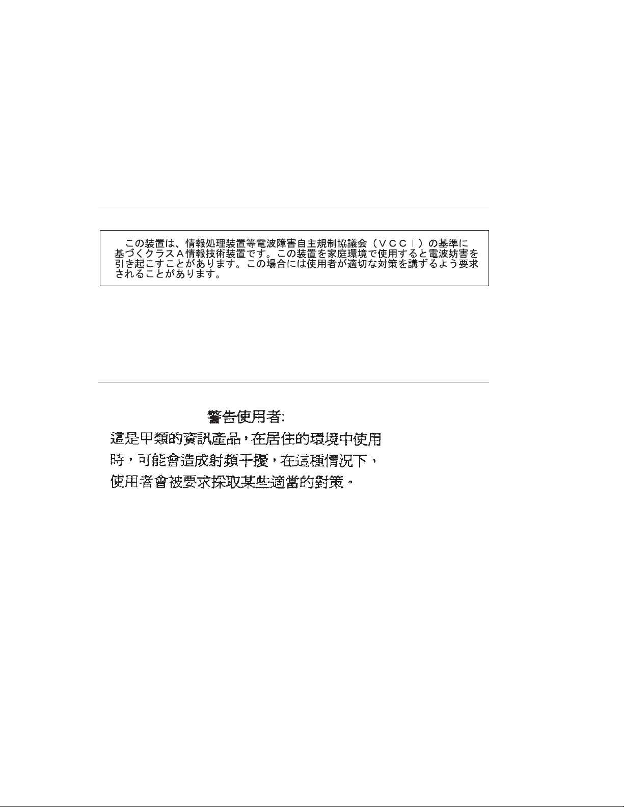
VCCI Statement
The following is a summary of the VCCI Japanese statement in the box above.
This is a Class A product based on the standard of the Voluntary Control Council for
Interference by Information Technology Equipment (VCCI). If this equipment is used
in a domestic environment, radio disturbance may arise. When such trouble occurs,
the user may be required to take corrective actions.
Electromagnetic Interference (EMI) Statement - Taiwan
The following is a summary of the EMI Taiwan statement above.
Warning: This is a Class A product. In a domestic environment this product may
cause radio interference in which case the user will be required to take adequate
measures.
Communications Statements xi
Page 14

Radio Protection for Germany
Dieses Gerät ist berechtigt in Übereinstimmung mit Dem deutschen EMVG vom
9.Nov.92 das EG–Konformitätszeichen zu führen.
Der Aussteller der Konformitätserklärung ist die IBM Germany.
Dieses Gerät erfüllt die Bedingungen der EN 55022 Klasse A. Für diese von
Geräten gilt folgende Bestimmung nach dem EMVG:
Geräte dürfen an Orten, für die sie nicht ausreichend entstört sind, nur mit
besonderer Genehmigung des Bundesministers für Post und Telekommunikation
oder des Bundesamtes für Post und Telekommunikation betrieben werden. Die
Genehmigung wird erteilt, wenn keine elektromagnetischen Störungen zu erwarten
sind.
(Auszug aus dem EMVG vom 9.Nov.92, Para.3, Abs.4)
Hinweis
Dieses Genehmigungsverfahren ist von der Deutschen Bundespost noch nicht
veröffentlicht worden.
xii 7046 Model B50 User's Guide
Page 15

Safety Notices
A
danger
death or serious personal injury.
4-2
A
caution
moderate or minor personal injury.
xiv
1-3
2-17
4-2
4-36
notice indicates the presence of a hazard that has the potential of causing
notice indicates the presence of a hazard that has the potential of causing
Danger
Caution
notices appear on the following pages:
notices appear on the following pages:
Copyright IBM Corp. 1999 xiii
Page 16
Laser Safety Information
The optical drive in the RS/6000 is a laser product. The optical drive has a label that
identifies its classification. The label, located on the drive, is shown below.
CLASS 1 LASER PRODUCT
LASER KLASSE 1
LUOKAN 1 LASERLAITE
APPAREIL A LASERDE CLASSE1
IEC 825:1984 CENELEC EN 60 825:1991
The optical drive in the RS/6000 is certified in the U.S. to conform to the
requirements of the Department of Health and Human Services 21 Code of Federal
Regulations (DHHS 21 CFR) Subchapter J for Class 1 laser products. Elsewhere,
the drive is certified to conform to the requirements of the International
Electrotechnical Commission (IEC) 825 (1st edition 1984) and CENELEC EN 60
825:1991 for Class 1 laser products.
CAUTION:
A class 3 laser is contained in the device. Do not attempt to operate the drive
while it is disassembled. Do not attempt to open the covers of the drive as it
is not serviceable and is to be replaced as a unit.
Class 1 laser products are not considered to be hazardous. The optical drive
contains internally a Class 3B gallium-arsenide laser that is nominally 30 milliwatts at
830 nanometers. The design incorporates a combination of enclosures, electronics,
and redundant interlocks such that there is no exposure to laser radiation above a
Class 1 level during normal operation, user maintenance, or servicing conditions.
xiv 7046 Model B50 User's Guide
Page 17
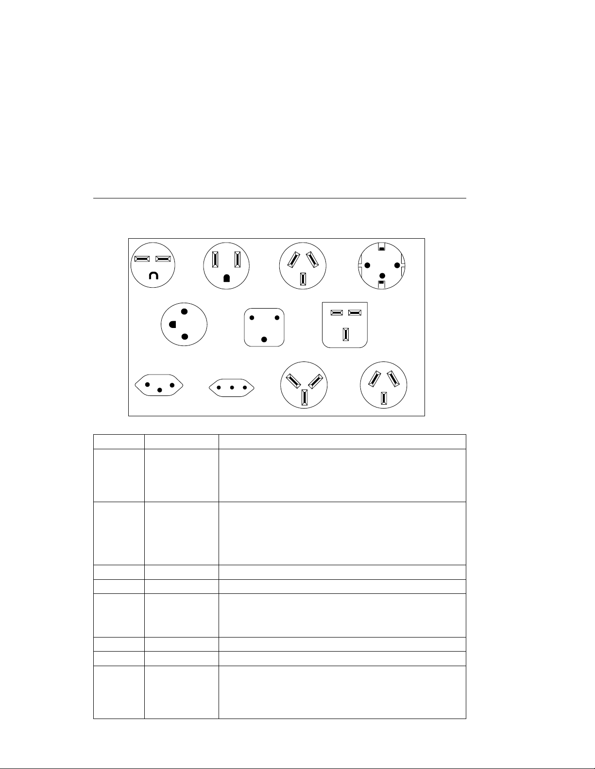
Power Cables
1
5
8
Index Part Number Country
1 1838574 Bahamas, Barbados, Bolivia, Brazil, Canada, Costa Rica,
2 6952300 Bahamas, Barbados, Bermuda, Bolivia, Brazil, Canada, Cayman
2 62X0663 Chicago, U.S.A. (Stackable)
3 6952311 Argentina, Australia, New Zealand
4 13F9979 Abu Dhabi, Austria, Belgium, Bulgaria, Botswana, Egypt, Finland,
5 13F9997 Denmark
6 14F0015 Bangladesh, Burma, Pakistan, South Africa, Sri Lanka
7 14F0033 Bahrain, Bermuda, Brunei, Channel Islands, Cyprus, Ghana,
23
6
9
Dominican Republic, El Salvador, Ecuador, Guatemala, Guyana,
Haiti, Honduras, Jamaica, Japan, Netherlands Antilles, Panama,
Peru, Philippines, Taiwan, Thailand, Trinidad, Tobago, U.S.A.
(except Chicago), Venezuela
Islands, Colombia, Costa Rica, Dominican Republic, Ecuador, El
Salvador, Guatemala, Guyana, Haiti, Honduras, Jamaica, Japan,
Korea (South), Mexico, Netherlands Antilles, Nicaragua, Panama,
Peru, Philippines, Puerto Rico, Saudi Arabia, Suriname, Trinidad,
Taiwan, U.S.A. (except Chicago), Venezuela
France, Germany, Greece, Iceland, Indonesia, Korea (South),
Lebanon, Luxembourg, Macau, Netherlands, Norway, Portugal,
Saudi Arabia, Spain, Sudan, Sweden, Turkey, Yugoslavia
Hong Kong, India, Iraq, Ireland, Jordan, Kenya, Kuwait, Malawi,
Malaysia, Nigeria, Oman, People's Republic of China, Qatar,
Sierra Leone, Singapore, Tanzania, Uganda, United Arab
Emirates (Dubai), United Kingdom, Zambia
10
7
4
11
Safety Notices xv
Page 18

Index Part Number Country
8 14F0051 Liechtenstein, Switzerland
9 14F0069 Chile, Ethiopia, Italy
10 14F0087 Israel
11 6952291 Paraguay, Colombia, Uruguay
xvi 7046 Model B50 User's Guide
Page 19

Environmental Notices
Product Recycling and Disposal
Components of the system unit, such as structural parts and circuit cards, can be
recycled where recycling facilities exist. Companies are available to disassemble,
reutilize, recycle, or dispose of electronic products. Contact your account
representative for more information. This system unit contains batteries and circuit
boards with lead solder. Before you dispose of this unit, these batteries and circuit
boards must be removed and discarded according to local regulations or recycled
where facilities exist. This book contains specific information on each battery type
where applicable.
Battery Return Program
In the United States, IBM has established a collection process for reuse, recycling, or
proper disposal of used IBM batteries and battery packs. For information on proper
disposal of the batteries in this unit, please contact IBM at 1-800-426-4333. Please
have the IBM part number that is listed on the battery available when you make your
call. For information on battery disposal outside the United States, contact your local
waste disposal facility.
Environmental Design
The environmental efforts that have gone into the design of this system signifies
IBM's commitment to improve the quality of its products and processes. Some of
these accomplishments include the elimination of the use of Class I ozone-depleting
chemicals in the manufacturing process and reductions in manufacturing wastes.
For more information, contact an IBM account representative.
Copyright IBM Corp. 1999 xvii
Page 20

xviii 7046 Model B50 User's Guide
Page 21

About This Book
This book provides information on how to install and remove options, use the
system, diagnostics, and service aids, and verify system operation. This book also
provides information to help you solve problems that might occur. Refer to
Chapter 8, “Determining Hardware Problems” if you have a problem with the server.
It contains procedures for determining if a problem is hardware or software related.
If a problem is software related, consult your operating system documentation.
ISO 9000
ISO 9000 registered quality systems were used in the development and
manufacturing of this product.
Online Publications
RS/6000 publications are available online. To access the online books, visit our Web
site at: http://www.rs6000.ibm.com/resource/hardware_docs/
Related Publications
The following publications are available:
The
The
The
The
The
Copyright IBM Corp. 1999 xix
RS/6000 7046 Model B50 Setup Instructions
pictorial guide designed to help you quickly set up your server if no internal
modifications are needed.
RS/6000 7046 Model B50 Service Guide
contains error codes, maintenance analysis procedures (MAPs), removal and
replacement procedures, and a parts catalog.
PCI Adapter Placement Reference
information regarding PCI adapter placement in your server.
, order number SA38-0538, contains
Diagnostics Information for Multiple Bus Systems
contains information and procedures that are common to all systems.
Adapter, Device, and Cable Information for Multiple Bus Systems
number SA38-0516, contains cabling and technical information about some of
the adapters and devices available for your server.
, order number SA38-0562, is a
, order number SA38-0564,
, order number SA38-0509,
, order
Page 22

Trademarks
The following trademarks apply to this information:
AIX is a registered trademark of International Business Machines Corporation.
PowerPC is a trademark of International Business Machines Corporation.
xx 7046 Model B50 User's Guide
Page 23

Chapter 1. Starting the System
Thank you for selecting the RS/6000 7046 Model B50!
The RS/6000 7046 Model B50 servers combine PowerPC 604e microprocessor
performance and system expandability, ensuring that your server adapts to handle
ever-changing operating requirements. The RS/6000 7046 Model B50 servers are
specifically designed to support the demands of network environments.
The RS/6000 7046 Model B50 servers incorporate the new, advanced peripheral
component interconnect (PCI) bus, which is faster than the industry standard
architecture (ISA) bus.
This book helps you set up and use your server, install and remove options,
configure your system, and use the system programs that are provided. This book
also provides information to help you solve some of the simpler problems that might
occur, and how to obtain assistance and service. Appendix A, “System Records”
provides a section for you to record all the important information about your server.
Copyright IBM Corp. 1999 1-1
Page 24
Before You Begin
Review the following list to ensure you are ready to begin:
Make sure you have the proper type and level of operating system supported for
your server. The Model B50 supports AIX Version 4.3.2 and later. If you are
unsure about whether an operating system is supported on your server, please
call your marketing representative.
Make sure you have an adequate number of properly grounded electrical outlets
for your server, display, and any other options you intend to install.
Place your server in a location that is dry. Rain or spilled liquids might damage
your server.
Collect the following tools and keep them handy:
– Small flat-blade screwdriver
– Medium flat-blade screwdriver
– Trays to hold screws.
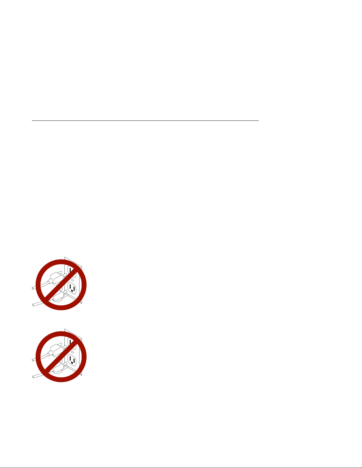
Safety Note: Before continuing, refer to the
Safety Information
Do
not
plug any cables into the system unit, adapters, or
electrical outlets until you have reviewed this information.
Make sure none of the power cords are connected
before continuing.
Safety Note: Before continuing, refer to the
Safety Information
Do
not
plug any cables into the server, adapters, or
electrical outlets until you have reviewed this information.
Make sure none of the power cords are connected
before continuing.
book for Danger and Caution notices.
book for Danger and Caution notices.
System Unit
System Unit
1-2 7046 Model B50 User's Guide
Page 25

Unpacking Your Server
CAUTION:
To avoid possible injury while moving or lifting your system unit, ask another
person to help you.
Preinstallation Checklist: After you unpack your server and optional devices,
make sure you have the following items:
Ø Server and power cord
Ø ASCII terminal, mouse, display, and keyboard (if ordered)
Ø Your operating system and documentation
Ø Options you want to install, such as adapters, media drives, or external
devices.
Contact your authorized reseller or marketing representative if any items are missing
or damaged.
Chapter 1. System Startup 1-3
Page 26

System Features
Bus Architecture
Two 32-bit PCI adapter slots are available:
Slot 2, primary (full size)
Slot 1, secondary (half size)
Microprocessor
PowerPC 604e 375 MHz with 1MB parity synchronous L2 cache
Memory
128MB-1GB SDRAM
4 memory module sockets for 128MB or 256MB dual inline memory modules
with ECC SDRAM EDO (extended data out)
Diskette Drive
Standard: 3.5-inch, 1.44MB
Drives
Hard Disk Drives
9.1GB and 18GB Ultra SCSI drives
Maximum supported: 2 internal
CD-ROM drive
32x speed 5.25-inch, with sliding tray (no caddy required)
Other Drives
Drive bays can accommodate 3.5-inch disk drives or CD-ROM drives.
1-4 7046 Model B50 User's Guide
Page 27

Power Supply
Autoranging 250 watt, usable with 115 Vac or 230 Vac (Supports
Wakeup-on-LAN)
Keyboard and Mouse (Optional)
Standard: 101 key Enhanced keyboard
Optional: 101/102 or 106 Enhanced Keyboard
Standard: 3-button mouse
Front-Panel Display
4-digit LED diagnostics display
Input/Output Ports
25-pin Parallel
9-pin Serial (2)
8-pin Tablet
Keyboard
Mouse
Ultra SCSI (16-bit)
100/10 Base 5 Ethernet
100/10 Base T Ethernet
Audio Line-in and Audio Line-out
Microphone
Headphone
Security Features
Power-on password
Privileged-access password
SCSI security jumpers on system board
Chapter 1. System Startup 1-5
Page 28
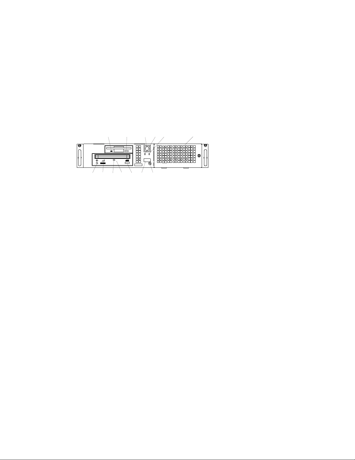
Front View
12
10 9 8 611
13
1 Power Switch: Turns server power
on and off.
2 Hard Disk Drive Status Light:
Glows when the server is reading from
or writing to the hard disk.
3 Power-On Light: Glows when the
server is on.
4 Disk Drive Bay Cover: Media bay
for diskette drive.
5 Reset Button: Function depends
upon the operating system installed.
6 Operator Panel Display: Function
depends upon the operating system
installed; may display current status of
server startup, or diagnostic information
in the event of a hardware problem.
1
2
3
75
7 CD-ROM Eject Button: Releases
the CD-ROM from the CD-ROM drive.
8 CD-ROM Emergency Eject: Ejects
CD-ROM from the CD-ROM drive if
power is not available.
9 CD-ROM Status Light: Indicates
when the CD-ROM drive is active.
10 CD-ROM Volume Control:
Controls the volume for the CD-ROM
headphone jack.
11 CD-ROM Headphone Jack:
CD-ROM headphone connector.
12 Diskette-Drive Status Light:
Glows when the server is reading from
or writing to a diskette.
13 Diskette Eject Button: Releases
diskette from 3.5-inch diskette drive.
4
1-6 7046 Model B50 User's Guide
Page 29

Rear View
789
1 2
6
1 Keyboard Port: ( ): For
keyboard connection.
2 Mouse Port ( ): For mouse
connection.
3 Parallel Port ( ): For connecting
a parallel printer or other parallel
devices.
4 Ethernet Port ( ): For
attaching your server to an
Ethernet/Twisted pair connection
through a 10 Base T or 100/10 Base T
connector.
5 External SCSI Port ( ):
For connecting external SCSI devices.
1 2
2
1
5
3
4
10
1
2
6 Audio Ports:
Headphone
Microphone
Audio line-out
Audio line-in
7 9-Pin Serial Ports
( 1 and
): For a TTY terminal,
2
Modem, or other serial devices.
8 Tablet Port ( ): For attaching a
digitizing tablet to your server.
9 Ethernet Port ( ): For attaching
your server to an Ethernet thick
connection (or Ethernet thin connection,
using an optional transceiver) through a
100/10 Base 5 connector.
10 Expansion Slots: For adding PCI
adapters.
Chapter 1. System Startup 1-7
Page 30

Installing Options
If you have options (such as adapters, diskette drives, hard-disk drives, or
memory-module kits) to install, go to Chapter 4, “Installing and Removing Options” to
install them. After you complete option installation and have updated your
configuration, return to this chapter to connect the cables and complete the server
installation.
Connecting the Cables
This section provides information on how to connect the various cables your server
may require, depending on your options.
1. If you are using a keyboard and display:
Attach the keyboard cable to the keyboard connector and the display to the
display connector on the back of the display adapter in one of the expansion
slots.
If you are installing a mouse or other pointing device, connect that cable.
Connect the display power cord to the display.
If you are using an ASCII terminal:
Connect the ASCII terminal cable to the S1 port on the server.
Connect the ASCII terminal power cord to the ASCII terminal.
2. Attach adapter cables to any adapters installed in the expansion slots. For more
instructions on adapter cabling, please refer to the documentation that came with
your adapter, or to the
Systems
3. Make sure all externally attached devices are turned off.
4. Connect the server power cord to the power connector on the server. Secure
the connection; then plug the display power cord and the server power cord into
properly grounded electrical outlets.
Attention: As soon as the server power cord is plugged into the server and power
outlet, the power is on within the server
not plug in the server power cord if the cover of the server is removed.
1-8 7046 Model B50 User's Guide
.
Adapter, Device, and Cable Information for Multiple Bus
whether or not the server is turned on.
Do
Page 31

Finishing the Installation
Your server hardware is set up, and you are ready to learn about your system and
make backup copies of important software. The order in which you do these tasks is
up to you. Use the following checklist as a guide:
Ø Record your identification numbers
Your server has important identification information that you might need if you
have it serviced.
Appendix A, “System Records” shows where to find these numbers, and
provides space to record and retain this information.
Ø Install the operating system
If AIX is preinstalled in your server, or if you plan to install AIX yourself, refer to
the AIX documentation for instructions.
Ø Install application programs
To install application programs, follow the instructions supplied with each
application program.
Chapter 1. System Startup 1-9
Page 32

1-10 7046 Model B50 User's Guide
Page 33

Chapter 2. Using the Server
This section provides information on how to start and use the server.
Starting the Server
Perform the following steps to start the server.
1. Turn on all attached devices.
2. Turn on the server.
3. If power does not come on when you turn on the server, ensure that the power
cord, located at the back of the server, is plugged in. If this does not solve the
problem, go to Chapter 8, “Determining Hardware Problems.”
When you turn on the server, the Power LED comes on and the server starts a
POST (power-on self test). During this test, the disk status LED flashes intermittently.
The server beeps a short beep, and progress indicators appear on the operator
panel display (if a display is attached).
Copyright IBM Corp. 1999 2-1
Page 34

Console Selection
After the server starts up, you can select the system console for your server if one
has not been chosen before (or if your display adapter configuration has changed).
The system console functions as the primary display and keyboard for your server.
On a graphical display, the console selection screen looks like the following
illustration:
If the console selection screen appears, each display and ASCII terminal attached to
your server appears with a number. To define a display or ASCII terminal as your
system console, press the number on the keyboard that corresponds to the system
console you choose.
If a console is not chosen after a certain amount of time, the server automatically
chooses an ASCII terminal as the system console (whether or not one is installed).
To choose another system console, you must shut down and restart the server.
2-2 7046 Model B50 User's Guide
Page 35

POST Indicators
If you are using an ASCII terminal (attached to serial port 1), a series of POST
indicators appear on the screen as each subsystem is initialized.
If you are using a directly attached keyboard and a graphical display attached to
a display adapter, then the POST progress indicators appear as icons across the
bottom of the display as follows:
Memory Modules: Tests system memory.
Keyboard: Initializes the keyboard and mouse. When this
icon appears, you can choose one of several different startup
options.
Pressing the F1 key or the numerical 1 key activates the
System Management Services.
Pressing the F5 key or the numerical 5 key invokes the
default boot list mode, located in firmware.
Pressing the F6 key or the numerical 6 key works like the
F5 key or numerical 5 key except firmware looks for a boot
record according to the custom bootlist that was setup by
System Management Services.
Pressing the F8 key or the numerical 8 key selects the
Open Firmware Command line.
If any of these keys are pressed, the chosen option occurs
after all of the POST icons appear. If no keys are pressed, the
server boots from the default boot list and starts the operating
system after all POST icons appear.
Network: Initializes network adapters.
SCSI: Initializes SCSI Adapters.
Chapter 2. Using the Server 2-3
Page 36

Audio: Initializes the audio system. For the audio system to
take effect, any startup option key must be pressed before the
end of audio initialization.
If the POST process stops and indicates an error on the LED or console in any one
of these subsystems, record the error number and refer to Chapter 8, “Determining
Hardware Problems.”
For more information on:
The System Management Services (started by pressing F1 or the numerical 1
key), see Chapter 3, “Using System Management Services.”
The Open Firmware command line (started by pressing F8 or the numerical 8
key), see Chapter 3, “Using System Management Services.”
Alternate boot modes (started by pressing F5 or the numerical 5 key, or F6 the
numerical 6 key), see “Working with System Startup Options.”
The last indicator to appear is the boot indicator. This indicator shows that the
server hardware is preparing to load and start the operating system.
At this point, the server prompts you for the power-on password if it has been set.
(See Chapter 3, “Using System Management Services,” for instructions on setting
passwords.)
If three incorrect responses are given to the password prompt, the server locks up
and must be turned off and turned on again to be reset. If the power-on password
has been lost, then the power-on password jumper must be reset or disabled:
To reset the power-on password, remove the server power cable; then remove
the server battery for 30 seconds. See “Changing the Battery” on page 4-36 for
the location of the battery.
To disable the power-on password, see “Enabling and Disabling the Power-On
Password” on page 4-8.
Attention: Removing the battery may also erase system configuration information
stored in the nonvolatile random access memory (NVRAM), such as the custom boot
list.
Note: If the privileged-access password has been lost, contact your authorized
reseller or marketing representative.
2-4 7046 Model B50 User's Guide
Page 37

If no bootable operating system image is found on any of the storage devices listed
in the system firmware boot list, then the server attempts to boot again. With each
attempt, you have the opportunity to start the System Management Services (SMS)
as described in Chapter 3, “Using System Management Services.”
Stopping the Server
Attention: When you use the shutdown procedure for your server, enter the correct
shutdown command for your operating system before you stop the server. Failure to
do so may result in the loss of data. If you need information on the shutdown
procedure for your operating system, see the operating system documentation.
1. Before stopping the programs and operating system, notify your system
administrator and users that the server is going to be shut down.
2. After you shut down the operating system, turn off the server.
3. Set the power switches of the attached devices to Off.
Using the Power Switch and Indicator
The power switch and indicators on the front of your server allow you to control
power to the server, observe server power status, and observe disk activity.
These features also have other built-in capabilities to assist you in diagnosing system
problems and observing server status:
When the server is turned on by pressing the power switch, the power LED lights
steadily.
The disk drive LED lights whenever the hard disk drives within the server are
being used.
If AIX is installed and running, a memory dump of system information can be
requested.
– To enable this function, the sysdumpdev -K command must be executed
before an error condition exists.
– To request the memory dump, press the reset button on the operator panel.
Requesting a memory dump directs AIX to save system information to a
predefined file before turning off the system. This feature can be used to
assist in recovery from system problems.
– When a memory dump has been requested, the power LED blinks quickly
(about 10 flashes per second) to indicate that the dump has been started.
This blinking ceases after about a minute whether or not the dump is
Chapter 2. Using the Server 2-5
Page 38

complete, and the LED returns to its steady, lit state until the system turns off
or reboots when the dump is complete.
– The memory dump file can be viewed by entering the AIX command
sysdumpdev -L
Using the Operator Panel and Reset Switch
The operator panel on the front of the server contains a four-digit display and reset
button. The four-digit display is used by your server to display progress indicators
during system startup, and can also display error messages.
The function of the reset button depends on the operating system installed in the
server. Consult your operating system documentation for a description of its
function.
Working with System Startup Options
If no keys are pressed after the server power is turned on, the server searches a list
of devices (the
then the server loads and starts the operating system. This is called a
default boot list
) for a bootable image. If a bootable image is found,
normal boot
.
The server can also be booted from a
through the System Management Services.
If certain keys are pressed during system startup, the server searches the default or
custom boot list for a bootable image to start in
mode. After a successful service mode boot, the diagnostic programs are started
automatically.
The following pages describe the default and custom boot lists, and how to boot from
these in either normal or service mode.
custom boot list
service mode
, which can be changed
instead of normal
Default Boot List
The
default boot list
types:
1. Diskette drive
2. CD-ROM drive
3. Disk drive
4. Network device
2-6 7046 Model B50 User's Guide
is composed of the first device found of each of the following
Page 39

If this default boot list is used during system startup, the server attempts to boot from
the diskette drive, then from the CD-ROM drive, then from the first disk drive
encountered, and finally the first network connection encountered.
Custom Boot List
The contents of the
Management Services or the text-based System Management Services. When the
custom boot list is used during system startup, the server attempts to boot in turn
from each specific device in the custom boot list.
Note: Only the specific devices contained in the custom boot list are checked for a
bootable image. Other devices of the same type are
bootable image unless they are also specified in the custom boot list. Refer
to Chapter 3, “Using System Management Services” for more information on
custom boot lists.
If no bootable image is found in the custom boot list, then the server restarts and
attempts to boot again.
If the custom boot list is discovered to be corrupted, the server rebuilds the custom
boot list according to the default boot list.
custom boot list
can be defined by using the graphical System
not
searched for a
Loading Diagnostics in Service Mode Boot
The server can be booted in service mode (instead of normal mode) from either the
default boot list or custom boot list. After a successful service mode boot, the
diagnostic programs are started automatically.
Booting in Service Mode from the Default Boot List
To boot in service mode from the default boot list, do the following:
1. Before stopping the programs and operating system, notify your system
administrator and users that the server is going to be shut down.
2. Insert the diagnostics CD-ROM into the CD-ROM drive, if you intend to run
standalone diagnostics.
3. Turn off the server.
4. Wait 30 seconds, then turn on the server.
5. When the keyboard indicator appears during startup, press the F5 key if the
system console is a directly attached keyboard, or the 5 key if the system
console is an ASCII terminal.
Chapter 2. Using the Server 2-7
Page 40

6. Enter any passwords.
Diagnostics loaded from CD-ROM are called
default boot list checks the CD-ROM drive before the disk drive, this procedure is
used to start standalone diagnostics.
standalone
diagnostics. Because the
Booting in Service Mode from the Custom Boot List
To boot in service mode from the custom boot list, do the following:
1. Before stopping the programs and operating system, notify your system
administrator and users that the server is going to be shut down.
2. Turn off the server.
3. Wait 30 seconds, then turn on the server.
4. When the keyboard indicator appears during startup, press the F6 key if the
system console is a directly attached keyboard, or the 6 key if the system
console is an ASCII terminal.
5. Enter any passwords.
Diagnostics loaded from a disk drive or network are called
diagnostics can be used only if AIX is installed.) Because the custom boot list lists
the disk drive or network device before the CD-ROM drive, this procedure is used to
start online diagnostics. To ensure that using the custom boot list starts online
diagnostics, do not insert the diagnostics CD-ROM.
online
diagnostics. (Online
2-8 7046 Model B50 User's Guide
Page 41

Working with Standalone versus Online Diagnostics
When the server attempts to boot in service mode (from either the default or custom
boot list) and locates a diagnostics CD-ROM before any other bootable image, then
the server starts standalone diagnostics.
Standalone diagnostics can be used on servers installed with any supported
operating system.
When the server attempts to boot in service mode (from either the default or custom
boot list) and first locates a bootable image on disk drive or network connection, then
the server starts online diagnostics.
Online diagnostics can be used only on servers installed with the AIX operating
system.
Because the type of diagnostics started (standalone or online) depends on the
source from which they are loaded, changing the boot list used during system startup
can affect which diagnostics are run.
Recommended Boot Options
The procedures under “Loading Diagnostics in Service Mode Boot” on page 2-7
produce the following recommended results:
Default boot list (F5 or 5 key) with diagnostics CD-ROM inserted loads
Standalone Diagnostics.
Custom boot list (F6 or 6 key) without diagnostics CD-ROM inserted loads Online
Diagnostics, if AIX is installed on a device in the custom boot list.
Chapter 2. Using the Server 2-9
Page 42

Summary of Boot Options and Control Keys
You can press the following keys when the keyboard POST indicator appears.
Key Result
F1 (display keyboard) Normal mode boot, graphical System Management Services
starts.
1 (ASCII keyboard) Normal mode boot, text-based System Management Services
starts.
F5 (display keyboard) Service mode boot, default boot list.
5 (ASCII keyboard) Service mode boot, default boot list.
F6 (display keyboard) Service mode boot, custom boot list.
6 (ASCII keyboard) Service mode boot, custom boot list.
F8 (display keyboard) Normal mode boot, Open Firmware command line.
8 (ASCII keyboard) Normal mode boot, Open Firmware command line.
2-10 7046 Model B50 User's Guide
Page 43

Using the Keyboards
There are several keyboards available with the server. The keyboards have various
keys that enter data and control the cursor location.
The functions of each keyboard depend on the software used. The character sets for
the keyboards are contained and explained in the documentation for your operating
system.
1
Num
Caps
Print
Esc F1 F2 F3 F4 F6 F7 F8F5 F9 F10 F11 F12 Pause
@
#
!
123
QWER YUIT OP
Tab
ASDFGHJKL :
Caps
Lock
Shift
Ctrl Alt
$% &
4567
ZXCVBNM
*
8
()
90
<
>
,
_
+
-
=
"
,
;
?
Shift
/.
Alt Ctrl
Backspace
Enter
Scroll
Screen
Lock
SysRq
Insert
Home
Delete
End
Break
Page
Up
Page
Down
Lock
Num
Lock
789
Home PgUp
End
0
Ins Del
Scroll
Lock
Lock
/*-
+
654
321
PgDn
Enter
.
2
3
4
The keyboard is divided into four sections:
1 - Function keys are multipurpose keys and their function is controlled by the
operating system.
2 - Typewriter keys are similar to a standard typewriter. Their function is controlled by
the software.
3 - Control keys move the cursor on the screen and do programmed control
functions. The movement and functions depend upon the application used.
4 - The Numeric keypad is arranged like a calculator to help when typing numbers.
Chapter 2. Using the Server 2-11
Page 44

On all of the keyboards, you can adjust the tilt position for typing comfort. To tilt the
keyboard, pull out on the keyboard legs. The legs snap into position. To decrease
the tilt of the keyboard, rotate the keyboard legs until they snap into the bottom of
the keyboard case.
The keyboard cable plugs into the connector at the rear of the server.
Using the Mouse
The mouse is a hand-operated locating device. Consult your application
documentation for the exact use of the three-button mouse.
You can use the mouse to perform functions such as positioning a cursor, selecting
items from a menu, or moving around in your document much easier and faster than
if you used only the keyboard. The cursor moves exactly as you move the mouse on
a flat surface, such as a desktop.
When you move the mouse around on a flat surface, the cursor moves on the
display screen; the movement changes the position of the cursor.
2-12 7046 Model B50 User's Guide
Page 45

With the mouse buttons, you can perform functions such as selecting and
deselecting options, extending your selection, or choosing a command. The precise
function of your mouse depends on the software you are using.
The mouse has a cable that plugs into a connector at the rear of the server.
Handling the Mouse Correctly
For best operation, handle the mouse with care. Incorrect handling can damage the
mouse.
Do not:
Operate the mouse on cloth, unfinished wood, newspaper, or carpet.
Drop or hit the mouse.
Carry the mouse by holding onto the cable.
Expose the mouse to extreme temperatures or direct sunlight.
Place the mouse in liquid spills.
Caring for the Mouse
The operating surface for the mouse should be smooth, clean, and flat. For
example, you can operate the mouse on the following surfaces:
Finished wood
Glass
Enamel
Plastic
Paper (except newspaper)
Metal
Rough surfaces collect contaminants that can be transferred to the interior of the
mouse by the ball. Rough surfaces can also cause the pads located on the bottom
of the mouse to prematurely wear. A deeply pitted surface could cause erratic
operation of the mouse. The surface you use should be free from spills, dirt, dust,
lint, wax, eraser dust, and other foreign matter.
To care for the mouse:
Inspect the work surface for spills or other contaminants.
Dust the work surface.
If you are using a paper pad, inspect it for wear and replace it if necessary.
Chapter 2. Using the Server 2-13
Page 46

Cleaning the Mouse
Use the following information to clean the mouse:
1. Remove the retaining ring by turning it counterclockwise, in the direction of the
arrow as shown in the illustration.
1
2
3
1 Retaining ring
2 Ball
3 Cavity
2. Remove the ball.
3. Inspect the ball for contaminants. Wipe it clean with a dry, lint-free cloth.
4. If the ball is dirty, wash it in warm, soapy water. Rinse and wipe the ball with a
lint-free cloth until dry.
5. Inspect the ball cavity in the mouse for foreign materials. If there are any foreign
materials, remove them.
6. Replace the ball.
7. Replace the retaining ring on the mouse and align it with the open slots in the
ball cavity.
8. Turn the retaining ring clockwise until the open slots are covered and you hear
the ring snap into place.
2-14 7046 Model B50 User's Guide
Page 47

Using the 3.5-Inch Diskette Drive
The following section provides information on 3.5-inch diskette drive.
Diskette Compatibility
The server has a 1.44MB diskette drive installed.
The 1.44MB diskette drive can format, read, and write diskettes compatible with the
following diskette drives:
1.0MB diskettes with 720KB formatted data capacity
2.0MB diskettes with 1.44MB formatted data capacity (HD).
Format the diskette according to its specified capacity.
Write-Protecting 3.5-Inch Diskettes
Write-protecting diskettes is necessary so that important information is not
accidentally lost. When diskettes are write-protected, you can read information from
the diskettes, but you cannot write information on them.
There is a write-protect tab on the 3.5-inch diskette.
To locate the write-protect tab, turn the diskette over with the label facing down.
To prevent writing onto a diskette, slide the write-protect tab to open the protect
slot.
Chapter 2. Using the Server 2-15
Page 48

To allow writing onto a diskette, slide the write-protect tab to cover the protect
slot.
Loading and Unloading the 3.5-Inch Diskette
To load a diskette into the drive, insert the diskette in the diskette drive with the
labeled metal shutter first. Push the diskette into the drive until you hear a click.
The click indicates that the diskette is securely in position in the drive.
To unload the diskette, push the diskette-unload button. The diskette unloads
partially from the drive. Remove the diskette.
2-16 7046 Model B50 User's Guide
Page 49

Using the CD-ROM Drive
CAUTION:
A Class 3 laser is contained in the device. Do not attempt to operate the device
while it is disassembled. Do not attempt to open the covers of the device, as it
is not serviceable and is to be replaced as a unit.
The CD-ROM is located in bay 2 of the server. Your CD-ROM drive looks like the
one shown in the illustration, and the controls are located as indicated.
1 Headphone jack
2 Volume control
3 Status Light
4 Tray opening
5 Emergency eject access
6 Load/unload button
When the CD-ROM is set to On, the status light indicates one of several conditions.
The following are status light states and the respective conditions of the CD-ROM
drive:
Off during standby with the CD-ROM loaded or unloaded
Blinks from the closing of the tray to completion of initialization
Blinks slowly when either the lens or disc is dusty
Blinks quickly when in the audio mode
Lights during data transfer operations
Lights steadily when some condition exists that should be checked.
Chapter 2. Using the Server 2-17
Page 50

Loading the CD-ROM Drive
Press the unload button to open the tray. Place the disc in the tray with the printed
side up. Push gently on the load/unload button. The drive automatically pulls the
tray into the drive and prepares the disc for reading.
Unloading the CD-ROM Drive
Push and hold the unload button until the drawer comes out and then remove the
disc.
Cleaning the CD-ROM Drive
This CD-ROM drive has an internal head-cleaning mechanism, and therefore does
not require an external cleaning device. The internal cleaning mechanism cleans the
head every time the tray is closed with a disc in the tray.
Always handle discs carefully by the edges to avoid leaving fingerprints or scratching
them (this helps the disc to maintain good readability). Wipe discs with a soft,
lint-free cloth or lens tissue. Always wipe in a straight line from the inner hub to the
outer rim.
2-18 7046 Model B50 User's Guide
Page 51

Performing an Emergency Eject
Note: Execute the following procedure only in an emergency, such as when the tray
does not open if the unload button has been pressed.
1. Insert a small diameter rod, such as a straightened paper clip, into the
emergency eject hole. (Refer to the illustration on page 2-17 for the location of
the emergency eject access.)
2. Push in the tool until you feel some resistance.
3. Maintain a small amount of pressure on the rod while pulling on the tray with
your fingernail.
4. Pull the tray open and remove the disc.
Note: Normally the tray makes a ratcheting sound when you pull it open using
the above procedure.
Chapter 2. Using the Server 2-19
Page 52

2-20 7046 Model B50 User's Guide
Page 53

Chapter 3. Using System Management Services
Use the System Management Services to view information about your server and to
perform such tasks as setting passwords and changing device configurations.
If you have chosen a graphical display as your system console, you can use the
graphical System Management Services described below. If you are using an ASCII
display as your system console, see “Text-Based System Management Services” on
page 3-23.
Graphical System Management Services
To start the Open Firmware command line or graphical System Management
Services, turn on or restart the server.
The firmware version installed in your server is displayed at the bottom right corner
of the initial logo screen. Please note the version number; processor upgrades may
require a specified version of firmware to be installed in your server. (Update
System Firmware is an option under the Utilities menu in the System Management
Services.)
After the logo is displayed, initialization icons appear across the bottom of the
screen.
To enter the graphical System Management Services, you must press the F1 key
after
the keyboard icon appears during startup.
If you have pressed the F1 key, the System Management Services screen appears
after the initialization and power-on self-test (POST) are complete.
Note: If you have installed a privileged-access password, you are prompted for this
password before you gain access to the System Management Services
menu.
Copyright IBM Corp. 1999 3-1
Page 54

After the System Management Services starts, the following screen displays:
3-2 7046 Model B50 User's Guide
Page 55

The System Management Services screen contains the following options:
Config: Enables you to view your system setup.
Multi-Boot: Enables you to set and view the default operating
system, modify the boot sequence, access the Open Firmware
command prompt, and work with other options.
Utilities: Enables you to set and remove passwords, control
the playing of system tones, enable the unattended start mode,
set and view the addresses of your system's SCSI controllers,
select the active console, view or clear the firmware error log,
and update your server's firmware program.
Exit: Returns you to the previous screen.
To select an icon, move the cursor with the arrow keys to choose which icon is
highlighted, then press the Enter key. You can also select an icon by clicking on it
with your left mouse button. To leave the current screen, either press the Esc key or
select the Exit icon.
Chapter 3. Using System Management Services 3-3
Page 56

Config
By selecting this icon, you can view information about the setup of your server. A list
similar to the following appears when you select the Config icon.
3-4 7046 Model B50 User's Guide
Page 57

If more than one screen of information is available, a blue arrow appears in the top
right corner of the screen. Use the Page Up and Page Down keys to scroll through
the pages.
Chapter 3. Using System Management Services 3-5
Page 58

MultiBoot
The options available from this screen allow you to view and set various options
regarding the operating system and boot sequence.
3-6 7046 Model B50 User's Guide
Page 59

The following describes the choices available on this screen.
Select Software: This option, if supported by the operating
system, allows you to choose which operating system to use.
This option is supported by AIX. However, not all operating
systems support this option.
If you receive an informational message saying that no
operating system is installed, then the system information in
nonvolatile storage may have been lost. This can happen if the
battery has been removed. To correct this situation, refer to
the bootlist reference in your AIX operating system
documentation.
Software Default: This option, if supported by the operating
system, enables you to select a default operating system for
your server.
Install From: Enables you to select a media drive from which
to install an operating system.
Chapter 3. Using System Management Services 3-7
Page 60

Boot Sequence: Enables you to view and change the custom
boot list (the sequence in which devices are searched for
operating system code). You may choose from 1 to 5 devices
for the custom boot list.
The default boot sequence is:
1. The primary diskette drive
2. The CD-ROM drive
3. Tape drive
4. Hard disk drive
5. Network device
To change the custom boot list, enter a new order in the New
column, then click on the Save icon. The list of boot devices is
updated to reflect the new order.
Attention To change the custom boot list back to the default
values, click on Default. If you change your startup sequence,
you must be extremely careful when performing
operations (for example, copying, saving, or formatting). You
can accidentally overwrite data or programs if you select the
wrong drive.
OK Prompt: Enables you to go directly to the Open Firmware
command prompt. The Open Firmware command prompt is
used for debugging and device driver development. For more
information about the operation of the Open Firmware
command prompt, refer to IEEE Standard 1275.
write
MultiBoot Startup: Clicking on this button toggles whether the
Multiboot menu appears automatically at startup.
3-8 7046 Model B50 User's Guide
Page 61

Utilities
Selecting this icon enables you to perform various tasks and view additional
information about your server.
The following describes the options available on this screen.
Password: Enables you to set password protection for turning
on the server and for using system administration tools.
Hard Disk Spin Up Delay: Enables you to change the spin up
delay for SCSI hard disk drives attached to your server.
Error Log: Enables you to view and clear the firmware error
log information for your server.
Chapter 3. Using System Management Services 3-9
Page 62

RIPL (Remote Initial Program Load): Allows you to select a
remote system from which to load programs through a network
adapter when your server is first turned on. This option also
allows you to configure network adapters which require setup.
SCSI ID: Allows you to view and change the addresses (IDs) of
the SCSI controllers attached to your server.
Update: Allows you to update the system firmware program.
Console: If you have more than one keyboard and display
attached to your server, or if you have an ASCII terminal
attached to your server in addition to a keyboard and display,
this tool allows you to define which one is active.
3-10 7046 Model B50 User's Guide
Page 63

Password
When you select this icon, the following screen is displayed.
Power-On Password
Setting a power-on password helps protect information stored in your server. If a
power-on password is set for your server, the Power-On status icon is shown in the
locked position. If a power-on password is not set, then the Power-On status icon is
shown in the unlocked position (as shown in the screen above).
When you select the Entry icon, a screen with eight empty boxes displays. Type
your password in these boxes. You can use any combination of up to eight
characters (A–Z, a–z, and 0–9) for your password. As you type a character, a key
appears in the box.
Chapter 3. Using System Management Services 3-11
Page 64

Press Enter when you are finished; you must type the password again for
verification.
If you type the password incorrectly, press Esc and start again.
After you have entered and verified the password, the power-on password status
icon flashes and changes to the locked position to indicate that the power-on
password is installed.
If you previously had set a power-on password and want to remove it, select the
Remove icon.
Notes:
1. If you want to disable an installed power-on password (but not erase it), move
the power-on password jumper as described in the section beginning on page
4-8. Moving the jumper back to the default position re-enables the power-on
password, unless it has been removed in the System Management Services
Utilities or by removing the battery.
2. If you
3. The server power cable
A password becomes effective only after the server is turned off and back on again.
3-12 7046 Model B50 User's Guide
forget
the power-on password, you can erase the password by shutting
down the server and removing the battery for at least 30 seconds. See
“Changing the Battery” on page 4-36 for details.
must
be disconnected before removing the battery.
Page 65

Remote Mode: The remote mode, when enabled, allows the system to start from
the defined boot device. This mode is ideal for network servers and other servers
that operate unattended. You
must
set a power-on password before you can enable
the remote mode. When the remote mode is set, the icon label changes to Remote
<On>.
If you remove the power-on password, the remote mode is automatically reset, and
the icon label returns to Remote <Off>.
Note: To use the remote mode feature for booting unattended devices, you must
enable the automatic power-up feature. See “Enabling Automatic Power-Up”
on page 4-13 for instructions on enabling the automatic power-up feature,
which allows the server to turn on whenever AC power is applied to the
server (instead of having the server wait for the power button to be pushed).
Privileged-Access Password
The privileged-access password protects against the unauthorized starting of the
system programs. To set the privileged-access password, you must first change a
jumper on the system board. See Chapter 4, “Installing and Removing Options” on
page 4-1 to locate and change the password-enabling jumper, then return here.
If the password-enabling jumper has been changed, select the Entry icon to set and
verify the privileged-access password.
When you select the Entry icon, a screen with eight empty boxes displays. Type
your password in these boxes. You can use any combination of up to eight
characters (A–Z, a–z, and 0–9) for your password. As you type a character, a key
appears in the box.
Chapter 3. Using System Management Services 3-13
Page 66

Press Enter when you are finished; you must type the password again for
verification.
If you type the password incorrectly, press the Esc key and start again.
Note: If an error occurs when you attempt to set the privileged-access password,
then make sure the password-enabling jumper has been changed. (See
Chapter 4, “Installing and Removing Options” on page 4-1 for instructions on
changing the password-enabling jumper.)
After you have entered and verified the password, the privileged-access password
icon flashes and changes to the locked position to indicate that your server now
requires the password you just entered before running system programs.
Attention:
1. Once the password-enabling jumper has been changed and the
privileged-access password has been set, great care must be taken to preserve
the privileged-access password.
If you set the privileged-access password and
later misplace it, your server must be returned for service.
To prevent loss of system use, record the privileged-access password
immediately whenever it is changed.
2. If no user-defined boot-list exists, and the privileged-access password has been
enabled, you are asked for the privileged-access password at startup every time
you boot your server.
Moving the password-enabling jumper back to the default position does
or erase the privileged-access password. Removing the jumper or moving the
jumper back to the default position only prohibits changing or disabling this password
with the System Management Services.
3-14 7046 Model B50 User's Guide
not
disable
Page 67

Hard Disk Spin Up Delay
This selection allows you to change the spin up delay for SCSI hard disk drives
attached to your server. Spin up delay values can be entered manually or you can
use a default setting. All values are measured in seconds. The default is two
seconds. After you have entered the new Spin up delay values, use the arrow keys
to highlight the Save icon and press Enter.
Chapter 3. Using System Management Services 3-15
Page 68

Error Log
Selecting this icon displays the log of errors that your server has encountered during
operations.
Selecting the Clear icon erases the entries in this log.
3-16 7046 Model B50 User's Guide
Page 69

RIPL
Selecting the Remote Initial Program Load (RIPL) icon gives you access to the
following selections.
The Set Address icon allows you to define addresses from which your server can
receive RIPL code.
Chapter 3. Using System Management Services 3-17
Page 70

If any of the addresses is incomplete or contains a number other than 0 to 255, an
error message displays when you select the Save icon. To clear this error, change
the incorrect address and select Save again.
The Ping icon allows you to confirm that a specified address is valid by sending a
test transmission to that address.
After choosing the Ping option, you are asked to indicate which communications
adapter (Token Ring or Ethernet) should be used to send the test transmission.
3-18 7046 Model B50 User's Guide
Page 71

The Config icon allows you to configure network adapters which require setup.
The next screen allows you to select the type of adapter you have just chosen (or
allow the system to select the type automatically). Use the arrow keys or mouse to
highlight a selection. To choose the highlighted selection, press the spacebar, then
highlight the OK icon and press Enter.
After choosing the adapter to configure, you can select the communications mode of
the chosen adapter (or allow the system to select the communications mode
automatically). As on the previous screen, use the arrow keys or mouse to highlight,
then press the spacebar to select. When you have selected the communications
mode, highlight the OK icon and press Enter.
Chapter 3. Using System Management Services 3-19
Page 72

SCSI ID
This selection allows you to view and change the addresses (IDs) of the SCSI
controllers attached to your server. To change an ID, highlight the entry by moving
the arrow keys, then enter another number. After you have entered the new address,
use the arrow keys or mouse to highlight the Save icon and press Enter.
At any time in this process, you can select the Default icon to change the SCSI IDs
to the default values.
3-20 7046 Model B50 User's Guide
Page 73

Firmware Update
This selection allows you to update the firmware in your server from an image on a
3.5 inch diskette.
To create a firmware diskette with the latest level of firmware available, see the
following Web site:
http://www.rs6ððð.ibm.com/support/micro
When you are prompted, insert the firmware update diskette containing the new
firmware image.
Attention: While the new firmware image is being copied into your server, you must
not
turn off the server. Turning off the server during the update process may render
your server inoperable.
After the firmware update is complete, shut down and restart the server.
If the firmware update does not complete successfully or the server does not restart
after the firmware update, contact your authorized reseller or marketing
representative.
Chapter 3. Using System Management Services 3-21
Page 74

Firmware Recovery
If a troubleshooting procedure has indicated that the firmware information in your
server has been damaged, perform a firmware recovery.
To perform a firmware recovery, do the following:
1. Locate your firmware update diskette.
2. Using another server, rename the *.img file on the firmware update diskette to
precover.img
3. Make sure your server is turned off.
4. Insert the firmware recovery diskette into your server.
5. Turn on your server.
6. When the keyboard indicator appears, press the 1 key if the system console is
an ASCII terminal, or the F1 key if the system console is a directly attached
keyboard.
7. When the System Management Services appear, choose Utilities and perform a
Firmware Update.
3-22 7046 Model B50 User's Guide
Page 75

Text-Based System Management Services
The text-based Open Firmware command line and System Management Services are
available if an ASCII terminal is attached to your server.
To start the text-based System Management Services instead of the Open Firmware
command line, press 1 on the ASCII terminal keyboard when the keyboard text
symbol appears during startup.
After the text-based System Management Services starts, the following screen
appears.
Note: The version of firmware currently installed in your server is displayed at the
top of each screen in the text-based System Management Services. Please
note the version number; processor upgrades may require a specified version
of firmware to be installed in your server. Update System Firmware is an
option under the Utilities menu.
à ð
System Management Services
1 Display Configuration
2 Multiboot
3 Utilities
4 Select Language
.------.
|X=Exit|
------'
====>
á
ñ
Selecting the numbered options provide capabilities described in this section.
After you have finished using the text-based System Management Services, type x
(for exit) to start your server.
Chapter 3. Using System Management Services 3-23
Page 76

Display Configuration
This option provides information about the setup of your server. A screen similar to
the following is displayed.
à ð
<Device Name>
PowerPC 6ð4
L2-Cache, ð512K
Memory
slotA=8MB
slotB=8MB
LPT
addr=3BC
COM
addr=3F8
COM
addr=2F8
Audio
Keyboard
Mouse
Diskette
addr=3Fð
Integrated Ethernet
addr=8ððð5AF67BD
SCSI cntlr id=7
.-----------. .-----------. .------.
|P=prev-page| |N=next-page| |x=Exit|
-----------' -----------' ------'
á
ñ
3-24 7046 Model B50 User's Guide
Page 77

MultiBoot Menu
The options available from this screen allow you to view and set various options
regarding the operating system and boot sequence.
à ð
Multiboot Menu
1. Select Software
2. Software Default
3. Select Install Device
4. Select Boot Devices
5. OK Prompt
6. Multiboot Startup
.------.
|X=Exit|
------'
===>
á
ñ
Select Software: If this option is supported by the operating system, this option
shows the names of the operating system installed. This option may not be
supported by all operating systems.
If you are running on AIX and you receive the following:
No Operating System Installed
This would mean that information in nonvolatile storage could have been lost, as
would happen if the battery had been removed. To re-create this value, run the
bootlist command under AIX with the appropriate parameter. See the bootlist
command in your AIX documentation.
Software Default: If this option is supported by the operating system, you can
select the default operating system to start the system. This option may not be
supported by all operating systems.
Select Install Device: Produces a list of devices, for example the CD-ROM, from
which the operating system is installed. Select a device, and the system searches
the device for an operating system to install and if supported by the operating system
in that device, the name of the operating system displays.
Chapter 3. Using System Management Services 3-25
Page 78

Select Boot Device: Provides a list of devices that can be selected to be stored on
the boot list. Up to five devices are supported.
OK Prompt: Provides access to the Open Firmware command prompt.
Multiboot Startup: Indicates whether between OFF and ON and selects if the
Multiboot menu invokes automatically on startup or not.
Select Boot Devices
Select this option to view and change the custom boot list, which is the sequence of
devices read at startup time.
à ð
Select Boot Devices
1. Display Current Settings
2. Restore Default Settings
3. Configure 1st Boot Device
4. Configure 2nd Boot Device
5. Configure 3rd Boot Device
6. Configure 4th Boot Device
7. Configure 5th Boot Device
.------.
|X=Exit|
------'
====>
á
ñ
Display Current Settings: Lists the current order of devices in the boot list. The
following screen shows an example of this display.
3-26 7046 Model B50 User's Guide
Page 79

à ð
Current Boot Sequence
1. Diskette
2. Ethernet (Integrated)
3. SCSI CD-ROM id=3 (slot=1)
4. SCSI 5ððMB Hard Disk id=6 (slot=1)
5. SCSI 5ððMB Hard Disk id=5 (slot=5)
.------.
|X=Exit|
------'
===>
á
ñ
Restore Default Settings: Restores the boot list to the default sequence of:
Primary diskette drive
CD-ROM drive
Tape id=5
Hard disk drive id=6
Network device.
Selecting any of the Configure Boot Device options displays a screen similar to the
following:
Chapter 3. Using System Management Services 3-27
Page 80

à ð
Configure Nth Boot Device
Device Number Current Position Device Name
1 1 Diskette
2 2 Ethernet
3 3 SCSI CD-ROM
5 -
.-----------. .-----------. .------.
|P=prev-page| |N=next-page| |X=Exit|
-----------' -----------' ------'
===>
4 4 SCSI 4.5GB Hard Disk
á
ñ
Attention: If no user-defined boot list exists, and the privileged-access password
has been enabled, you are asked for the privileged-access password at
startup every time you boot up your server. See “Set Privileged-Access
Password” on page 3-31 for more information on the privileged-access
password.
3-28 7046 Model B50 User's Guide
Page 81

Utilities
The Utilities screen enables you to select from the following system management
tools.
à ð
Utilities
1. Set Passwords and Unattended Start Mode
2. SCSI Spin-Up
3. Display Error Log
4. Remote Initial Program Load Setup
5. Change SCSI id
6. Update System Firmware
7. Select Console
.------.
|X=Exit|
------'
===>
á
ñ
Chapter 3. Using System Management Services 3-29
Page 82

Set Password and Unattended Start Mode
Entering this selection permits access to the following options.
à ð
Password Utilities
1. Set Power On Password
2. Remove Power On Password
3. Unattended Start Mode <OFF>
4. Set Privileged-Access Password
5. Remove Privileged-Access Password
.------.
|X=Exit|
------'
===>
á
ñ
Set Power On Password: Setting a power-on password helps protect
information stored in your server. You can use any combination of up to eight
characters (A–Z, a–z, and 0–9) for your password. The password you type is not
displayed on the screen. Press Enter when you are finished; you must type the
password again for verification.
If you previously had set a power-on password and wanted to remove it, select
Remove Power-On Password.
Notes:
1. If you want to disable an installed power-on password (but not erase it) move the
power-on password jumper as described in “Enabling and Disabling the
Power-On Password” on page 4-8. Moving the jumper back to the default
position re-enables the power-on password, unless it has been removed in the
System Management Services Utilities or by removing the battery.
2. If you
3. The server power cable
forget
your password, you can erase the password by shutting down the
server and removing the battery for at least 30 seconds. See “Changing the
Battery” on page 4-36 for details.
must
be disconnected before removing the battery.
A password becomes effective only after the server is turned off and back on.
3-30 7046 Model B50 User's Guide
Page 83

Set Privileged-Access Password: The privileged-access password protects
against the unauthorized starting of the system programs.
To set the privileged-access password, you must first change a jumper on your
server's system board. See Chapter 4, “Installing and Removing Options” on
page 4-1 to locate and change the password-enabling jumper.
If the password-enabling jumper has been changed, select Set privileged-access
password to set and verify the privileged-access password.
Attention:
1. Once the password-enabling jumper has been changed and the
privileged-access password has been set, great care must be taken to preserve
the privileged-access password.
later misplace it, your server must be returned for service.
To prevent loss of system use, record the privileged-access password
immediately whenever it is changed.
2. If no user-defined boot-list exists, and the privileged-access password has been
enabled, you are asked for the privileged-access password at startup every time
you boot your server.
Moving the password-enabling jumper back to the default position does not disable
or erase the privileged-access password. Removing the jumper or moving the
jumper back to the default position only prohibits changing or disabling this password
with the System Management Services. Removing the battery does not affect the
state of the privileged-access password.
If you set the privileged-access password and
If you previously had set a privileged-access password and want to remove it, select
Remove Privileged-Access Password.
Hard Disk Spin Up Delay
Selecting this utility allows you to adjust the hard disk spin up delay in your server.
Chapter 3. Using System Management Services 3-31
Page 84

Display Error Log
A screen similar to the following displays when you select this option. You can view
or clear your server's error log.
à ð
.----------------------------------------------------------.
| Error Log |
| |
| Date Time ErrorCode Location |
| Entry 1. ð1/ð4/96 12:13:22 25A8ðð11 ðð-ðð |
| Entry 2. no error logged |
----------------------------------------------------------'
.-----------------. .------.
|C=Clear Error Log| |X=Exit|
-----------------' ------'
á
ñ
Note: The time stamp in this error log is Coordinated Universal Time (CUT), which
is also referred to as Greenwich Mean Time (GMT). AIX error logs have
more information available and can time stamp with your local time.
3-32 7046 Model B50 User's Guide
Page 85

Remote Initial Program Load Setup
This option allows you to enable and set up the remote startup capability of your
server. You must first specify the network parameters as shown in the following
screen:
à ð
Network Parameters
1. IP Parameters
2. Adapter Parameters
3. Ping
.------.
|X=Exit|
------'
===>
á
Selecting the IP Parameters option displays the following screen:
à ð
IP Parameters
1. Client IP Address [ððð.ððð.ððð.ððð]
2. Server IP Address [ððð.ððð.ððð.ððð]
3. Gateway IP Address [ððð.ððð.ððð.ððð]
4. Subnet Mask [ððð.ððð.ððð.ððð]
.------.
|X=Exit|
------'
===>
á
ñ
ñ
Chapter 3. Using System Management Services 3-33
Page 86

Select the Adapter Parameters option to view an adapter's hardware address, as well
as configure network adapters that require setup. A screen similar to the following
displays:
à ð
Adapter Parameters
Device HW Address
1. 3Com,3C9ð5 8ððð5AFC67BD
2. token-ring 8ððð32E54A12
.------.
|X=Exit|
------'
á
ñ
3-34 7046 Model B50 User's Guide
Page 87

Selecting option 1 (3Com,3C905) displays the following 100Mb Ethernet
configuration menu:
à ð
3Com Etherlink Fast XL
1. Media Type [Auto]
2. Full Duplex [Auto]
.------.
|X=Exit|
------'
á
ñ
Selecting the Media Type option allows you the change the media employed by the
Ethernet adapter:
à ð
.----------------.
----------------'
á
| MEDIA TYPE |
| 1. 1ð BaseT |
| 2. 1ðð Base TX |
| 3. Auto |
ñ
Chapter 3. Using System Management Services 3-35
Page 88

Selecting the Full Duplex option allows you to change how the Ethernet adapter
communicates with the network:
à ð
.----------------.
----------------'
á
Select Ping from the Network Parameters menu to test a connection to a remote
server. After selecting the Ping option, you must choose an adapter to communicate
with the remote system.
| Full Duplex |
| 1. Yes |
| 2. No |
| 3. Auto |
ñ
à ð
Interface
1. Ethernet
2. Token Ring
===>
á
3-36 7046 Model B50 User's Guide
ñ
Page 89

After determining which adapter to use to ping the remote system, you must provide
the addresses needed to communicate with the remote system. Select the
appropriate device from the Ping menu to display a screen similar to the following:
à ð
Ping
1. Client IP Address [129.132.4.2ð]
2. Server IP Address [129.132.4.1ð]
3. Gateway IP Address [129.132.4.3ð]
4. Subnet Mask [255.255.255.ð]
.---------. .------.
|E=Execute| |X=Exit|
---------' ------'
===>
á
ñ
Change SCSI ID
This option allows you to view and change the addresses of the SCSI controllers
attached to you server.
Update System Firmware
This option allows you to update your system firmware. Note that you must insert a
diskette containing the firmware update image after you see a confirmation screen.
To create a firmware diskette with the latest level of firmware available, see the
following Web site:
http://www.rs6ððð.ibm.com/support/micro
When you are prompted, insert the firmware update diskette containing the new
firmware image.
Chapter 3. Using System Management Services 3-37
Page 90

à ð
.--------------------------------------------------------------.
| This selection will update your System Firmware. Do you want |
| to continue? Press Y(Yes) N(No). |
--------------------------------------------------------------'
á
ñ
Firmware Recovery: If a troubleshooting procedure has indicated that the
firmware information in your server has been damaged, perform a firmware recovery.
To perform a firmware recovery, do the following:
1. Locate your firmware update diskette.
2. Using another server, rename the *.img file on the firmware update diskette to
precover.img
3. Make sure your server is turned off.
4. Insert the firmware recovery diskette into your server.
5. Turn on your server.
6. When the keyboard indicator appears, press the 1 key on the system console
ASCII terminal.
7. When the System Management Services appear, choose Utilities and perform a
System Firmware Update as previously described.
3-38 7046 Model B50 User's Guide
Page 91

Select Console: Select this option to define which display is used by the system
for system management.
Select Language
Select this option to change the language used by the text-based System
Management Services screens.
à ð
SELECT LANGUAGE
1. English
2. Francais
3. Deutsch
4. Italiano
5. Espanol
6. Svenska
====> .------.
|x=Exit|
------'
á
Note: Your ASCII terminal must support the ISO-8859 character set to properly
display languages other than English.
ñ
Chapter 3. Using System Management Services 3-39
Page 92

Open Firmware Command Line
The text-based Open Firmware command line allows you to configure some
adapters, and the System Management Services makes it possible for you to view
information about your server and to perform such tasks as setting passwords and
changing device configurations.
To enter the Open Firmware command line, press the 8 key
symbol appears
If you have pressed the 8 key, the Open Firmware command line (an OK prompt)
appears after the initialization and power-on self tests (POST) are complete.
The Open Firmware command line can be used to set up adapters that are not
configurable with the System Management Services. Your adapter documentation
directs you to use this option if it is needed.
during startup.
after the keyboard text
3-40 7046 Model B50 User's Guide
Page 93

Chapter 4. Installing and Removing Options
Adding hardware options to your server increases its capabilities. Many options are
available (see “Available Options” below). This chapter can help you decide which
options to add to your server, and shows you how to install them. When adding an
option, use these instructions along with those that came with the option.
If you have installed (or removed) options previously, you might be able to perform
some activities without detailed instructions. These activities are listed in the “Before
you begin” boxes of the procedures.
Before you install or remove an option, be sure you are familiar with the safety
procedures and component-handling guidelines described in “Safety Considerations”
on page 4-2. These precautions and guidelines help you work safely with your
server or options.
Available Options
The following are some of the options available for your server. Check with your
authorized reseller or marketing representative for the latest information.
Peripheral Component Interconnection (PCI) adapters
Additional system memory in the form of memory modules
Cabling an Ultra SCSI adapter
Internal drives
Microprocessor upgrades
Enable or disable the power-on password
Enable or disable the privileged-access password
Enable or disable automatic power-up
Enable or disable the external SCSI connector
Copyright IBM Corp. 1999 4-1
Page 94

Safety Considerations
Observe the following safety precautions anytime you work with the server.
DANGER
An electrical outlet that is not correctly wired could place hazardous
voltage on metal parts of the system or the devices that attach to the
system. It is the responsibility of the customer to ensure that the outlet
is correctly wired and grounded to prevent an electrical shock.
Before installing or removing signal cables, ensure that the power
cables for the system unit and all attached devices are unplugged.
When adding or removing any additional devices to or from the system,
ensure that the power cables for those devices are unplugged before
the signal cables are connected. If possible, disconnect all power
cables from the existing system before you add a device.
Use one hand, when possible, to connect or disconnect signal cables
to prevent a possible shock from touching two surfaces with different
electrical potentials.
During an electrical storm, do not connect cables for display stations,
printers, telephones, or station protectors for communication lines.
CAUTION:
This product is equipped with a three–wire power cable and plug for the user's
safety. Use this power cable with a properly grounded electrical outlet to avoid
electrical shock.
DANGER
To prevent electrical shock hazard, disconnect the power cable from
the electrical outlet before relocating the server.
4-2 7046 Model B50 User's Guide
Page 95

Handling Static Sensitive Devices
Attention: Static electricity can damage this device and your system unit. To avoid
damage, keep this device in its static protective bag until you are ready to install it.
To reduce the possibility of electrostatic discharge, follow the precautions listed
below.
Electrostatic Discharge Protection
To prevent electrostatic discharge:
Limit your movement. Movement can cause static electricity to build up around
you.
Handle the device carefully, holding it by its edges or its frame.
Do not touch solder joints, pins, or exposed printed circuitry.
Do not leave the device where others can handle and possibly damage the
device.
While the device is still in its anti-static package, touch it to an unpainted metal
part of the system unit for at least two seconds. (This drains static electricity
from the package and from your body.)
Remove the device from its package and install it directly into your system unit
without setting it down. If it is necessary to set the device down, place it on its
static-protective package. (If your device is an adapter, place it component side
up.) Do not place the device on your system unit cover or on a metal table.
Take additional care when handling devices during cold weather as heating
reduces indoor humidity and increases static electricity.
Tools Required
To install or remove options from your server, you need a flat-blade screwdriver.
Any additional tools needed depend upon the specific option and are noted in the
instructions that come with the option.
Chapter 4. Installing and Removing Options 4-3
Page 96

Removing the Cover
Before you begin:
Read “Safety Considerations” on page 4-2 and “Handling Static Sensitive
Devices” on page 4-3.
1. Remove any media (diskette or CD) from the drives.
2. Shut down programs as described in your operating system documentation.
3. Turn off all attached devices and the server.
4. If you have a modem or fax machine attached to the server, disconnect the
telephone line from the server.
5. Unplug all power cords (cables) from electrical outlets.
Attention: As soon as the server power cord is plugged in to the server and
power outlet, the power is on within the server
turned on.
removed.
4-4 7046 Model B50 User's Guide
Do not plug in the server power cord if the cover of the server is
whether or not the server is
Page 97

6. Make a note of where the other cables and cords are connected to the back of
the server, then disconnect them.
7. Unscrew the two front thumbscrews that secure the server to the rack.
8. Gently slide the server out of the rack until you encounter the spring detents.
9. Release the spring detents by pressing in on each spring detent on both sides of
the server at the same time. While pressing in, continue to slowly slide the
server out of the rack until the spring detents are completely out of the rack.
10. Place the server on a flat surface.
11. Unscrew the three thumbscrews located at the rear of the server.
2
1 2
Chapter 4. Installing and Removing Options 4-5
1
Page 98

12. Slide the cover to the rear approximately 1 inch.
13. Grasp the cover on both sides and lift it away from the server.
Locating Options
To locate various options in the server, use the following figure:
1
2
3
4
1 Adapter slots
2 Memory module connectors
3 Battery
4 Drive bays
4-6 7046 Model B50 User's Guide
Page 99

What to do next?
To enable or disable:
The privileged-access password, go to page 4-11.
The automatic power-up feature, go to page 4-13.
The power-on password, go to page 4-8.
The external SCSI connector, go to page 4-33.
To install:
A memory module, go to page 4-16.
An adapter, go to page 4-23.
An internal drive, go to page 4-29.
A new battery, go to page 4-36.
To remove:
An adapter, go to page 4-26.
A memory module, go to page 4-20.
An internal drive, go to page 4-29.
To complete the installation, go to page 4-39.
Chapter 4. Installing and Removing Options 4-7
Page 100

Enabling and Disabling the Power-On Password
Before you begin:
Read “Safety Considerations” on page 4-2 and “Handling Static Sensitive
Devices” on page 4-3.
Remove the server cover (see “Removing the Cover” on page 4-4).
Your server arrives from the factory with the power-on password enabled (but unset).
You can disable the power-on password by changing the position of a jumper on the
system board.
Notes:
1. Moving the jumper to the default position re-enables the power-on password,
unless it has been removed in the System Management Services Utilities or by
removing the battery.
2. If you
3. The server power cable
To disable the power-on password, complete the following steps:
1. Locate jumper J20 using the following illustration.
2. Remove any adapters that are blocking the jumper.
forget
the power-on password, you can erase the password by shutting
down the server and removing the battery for at least 30 seconds. See
“Changing the Battery” on page 4-36 for details on removing the battery.
must
be disconnected before removing the battery.
4-8 7046 Model B50 User's Guide
 Loading...