

Page 1

I
E T
CUSTOMER
ENGINEERING
B-1
ADJUSTMENT
MANUAL
Page 2
®
ETD
CUSTOMER
ENGINEERING
8-1
ADJUSTMENT
MANUAL
all nOgk
ts
to
reproduce t
Ms
matenOal are reserved
by
IBM
Page 3
TABLE
OF
CONTENTS
BACKSPACE
CARRIAGE.
CARRIAGE RETURN
ESCAPEMENT
KEYLEVERS
AND
CAMS 7
MARGIN RELEASE
MARGIN SET
MOTOR
AND
DRIVE
OPERATIONAL CAMS
PAPER
FEED.
RAILS
· 19
9
•
32
4
•
13
•
12
1
•
1'8
·
14
· 11
RIBBON
•
40
RIBBON LIFT o 43
SHIFT
SPACEBAR.
TABULATION.
• 23
• 39
.26
Page 4
MOTOR AND
DRIVE
MODEL
B1
ADJUSTMENTS
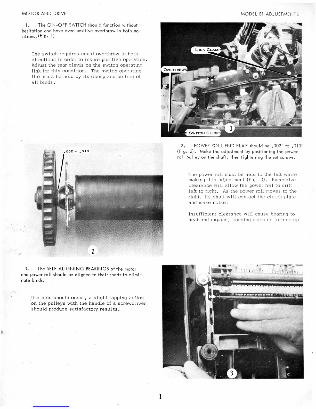
1. The
ON-OFF
hesitation and have
sitions.
(Fig.
The
switch
directions
Adjust
link
link
all
the rear
for
must be
binds.
1)
requires
in
this
SWITCH
even
positive overthrow
equal
order
to
clevis
condition.
held
by
its
should function without
in
both
overthrow
insure
on
the
The switch
clamp
positive
switch opera
and
in
both
operation.
operating
be
free
po-
ting
of
2.
(Fig.
roll
POWER
2).
Make
pulley
on the
The power
making
clearance
left
to
right,
and
its
make
ROLL
the
adjustment by positioning the power
shaft,
roll
this
adjustment (Fi
will
right.
shaft
noise"
END
then
must be
allow
As
the
will
PLAY
should be
tightening
held
to
g"
the
pow
power roll
contact the
.002"
the set screws.
the
left while
3)"
Excessiv
e r
roll
to
moves
clutch
to
drift
to the
plate
.010"
e
" 0
3. The
SELF
ALIGNING
and power roll should
nate
binds.
If
a
bind
should
on
the
pulleys
should
produce
BEARINGS
be
aligned
occur
I a
with
the
satisfactory
to
their
slight
handle
of
the
motor
shafts to
tapping
of a screwdriver
resul
ts.
elimi-
action
Insufficient
heat
and
expa
clearanc
nd I ca
e w
us
ill
ing
cause
machine
bearing
to lock
to
up"
1
Page 5

MODEL
B1
ADJUSTMENTS
5.
POWER
ROLL
SPEED
is
adjusted
by a two-step
motor
pu
Iley o The motor
pulley
shou
Id
be positioned on
the motor shaft to
align
the belts
~nd
the
pulleys (Fig.
5).
A
14-tooth
pulley
is
generally
used
for
the
Elite
or
12
pitch
type
styles, while
the
15-
tooth
pulley is
us
ed
for
the
larg
er
Pica
type
styles
or
bold
face type sty
les.
'
2
MOTOR AND
DRIVE
40
Adjust the
DRIVEN
BELT
by positioning the
inter
-
mediate
pulley
shaft.
The shaft incorporates a
left-hand
thread
so
that
pulley
rotation tends
to
ti ghten the
shaft.
The
deflection
of
the belt should
be
approximately 3/
8"
(Fig.
4).
60 Adjust
the
DRIVE
BELT
for approximately 3/ 16"
deflection
by positioning the motor adiusting screw for-
ward or back
in
its
elongated
mounting hole
(Fig.
4).
To
adjust
the
drive
belt
tension
on
ring
mount-
ed
motors,
loosen
the
motor
adjusting
screw
and
the
ring
mount
bracket
screw
(Fig
~
6).
The
motor
may
then
be
moved
front
to
rear
for
pro-
per
belt
tension.
After
tightening
these
screws,
check
the
motor
housing
to
be
sure
it
is
paral-
lel
to
the
frame
and
that
the
ring
mount
screws
are
tight.
To
adjust
the
drive
belt
tension
on
the
shaft
mounted
motor I it
is
necessary
only
to
loosen
the
motor
adjusting
screws.
Page 6

MOTOR
AND
DRIVE
The
following
are
the
effects
of
loose
or
tight
belts:
LOOSE BELTS
1.
Belt
noise
2.
Belt
climbing
on
pulley
3.
Uneven
impression
(due
to
momentary
slowing
of
the
power
roll
after
shift
or
backspace
operation).
4.
Be
lt
falling
off
when
machine
is
moved
TIGHT BELTS
1.
Belt
noise
2.
Motor
vibration
transmitted
to
machine
3.
Failure
of
motor
to
start
(extremely
tight
belts)
.
Properly
adjusted
belts
should
run
quietly,
bounce
only
slightly
during a shift
operation,
and
allow
the
drive-mechanism
to
coast
to a smooth
stop
as
the
switch
is
turned
off.
MODEL
Bl
ADJUSTMENTS
3
Page 7

MODEL
B1
ADJUSTMENTS
ESCAPEMENT
1.
. The MAIN SPRING tension
the
loop
of
the-
carriage
the
spring drum
(Fig.
7).
tension
is
tape
adjusted by
on
various lugs
placing
of
k
Carr.
CAUTION:
tens
injury
ning s pring
Length
12"
16"
20'
24"
20"
ion
can
.'
.
tape
Use
loop
result
drum.
Extreme
extreme
from
Left
2
1/2
2
1/2
2
3/4
2
3/4
3 4
care
from s pring
fingers
Extreme
3
3
3
3
when
drum.
caught
Right
3/8
Ib
1/2
Ib
5/8
Ib
7/8
Ib
1/8
Ib
removing
Serious
by
spin-
Carriage
full
left
riage
(excluding
is
measured
should
tension
to
the
with
measure
full
air
as
should
right
cylinder
the
push
follows
be
checked
position
range).
pull
(Fig.
of
scale
8).
from
the
Tension
and
the
car-
4
2.
Adjust UNIVERSAL
the escapement pawl
g.
9)
(Fi
~
at
the same
BAR
so
that
di
stElnce
all
from
typebars
the
trip
PLATE
N
Page 8
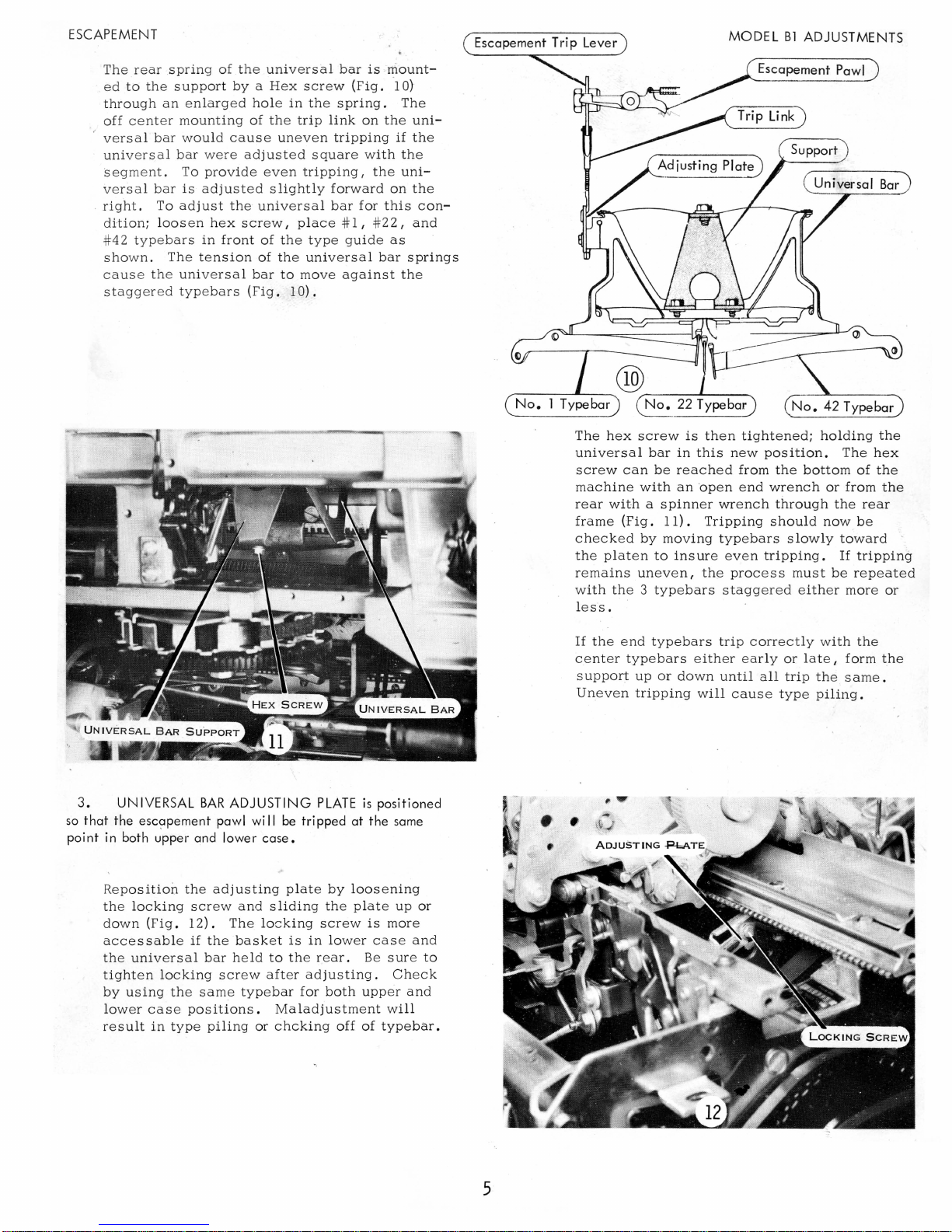
ESCAPEMENT
The
rear ,spring
ed
to
the
through
off
center
versal
universal
segment.
versal
,
right.
dition;
#42
typ
shown.
cause the
staggered
of
the
support by a Hex
an
enlarged
mounting
bar
would
bar
To
bar
is
To
adj
loosen
eba
rs
The
universal
typebars
cause uneven
were
provide
adjusted s lightly
ust
the
hex
scr
in
front
tension
universal
screw
hole
in
the
of
the
trip
adjusted
even
universal
ew I place # I,
of the
of
bar
(Fig.
square
tripping I the
type
the
universal
to
move
10).
bar
is ,mount-
(Fig.
spring.
link
on
tripping
with
forward
bar
for
guide
against
the
on
this
#22,
as
bar
'10)
The
uni-
if
the
the
uni-
the
and
springs
the
con-
Escapement Trip Lever
No.1
Typebar
The
hex
universal
screw
machine
rear
frame
checked
the
platen
remains
with the 3
l
ess
No.
22 Typebar
screw
can
with a spinner
(Fig.
uneven,
.
bar
be
with
11).
by
moving
to
typebars
is
in
reached
an 'open
insure
MODEL
then
tightened;
this
new
from
end
wrench
Tripping
typebars
even
the
proces s must
staggered
Bl
ADJUSTMENTS
, Escapement Pawl
holding
position.
the
wrench
through
should
slowly
tripping.
bottom
now
either
The
or
from
the
toward
If
be
more
repeated
Bar
the
hex
of
the
the
rear
be
tripping
or
3.
so
that
point
UNIVERSAL
BAR
the escapement pawl
in
both u'pper and lower
Reposition
the
locking
down
accessable
the
universal
tighten
by
using
lower
result
(Fig.
locking
case
in
the
screw
12).
if
bar
the
same
positions.
type
the
piling
ADJUSTING
wi
II
case.
adjusting
and
sliding
The
locking
basket
held
to
screw
after
type
or
PLATE
is
positioned
be
tripped at the same
plate
by
loosening
the
plate
up
screw
is
more
is
in
low
er
case
the
rear.
adjusting.
bar
for
Maladjustment will
chcking
both
off
Be
upp
of
typebar.
sure
Check
er
or
and
and
to
If
the
center
support
Uneven
end
typebars
typebars eith
up
or
down
tripping
trip
will
correctly
er early
until
all
cause
or
late I form
trip
type
with
the
same.
piling.
the
the
5
Page 9
MODEL
Bl
ADJUSTMENTS
ESCAPEMENT
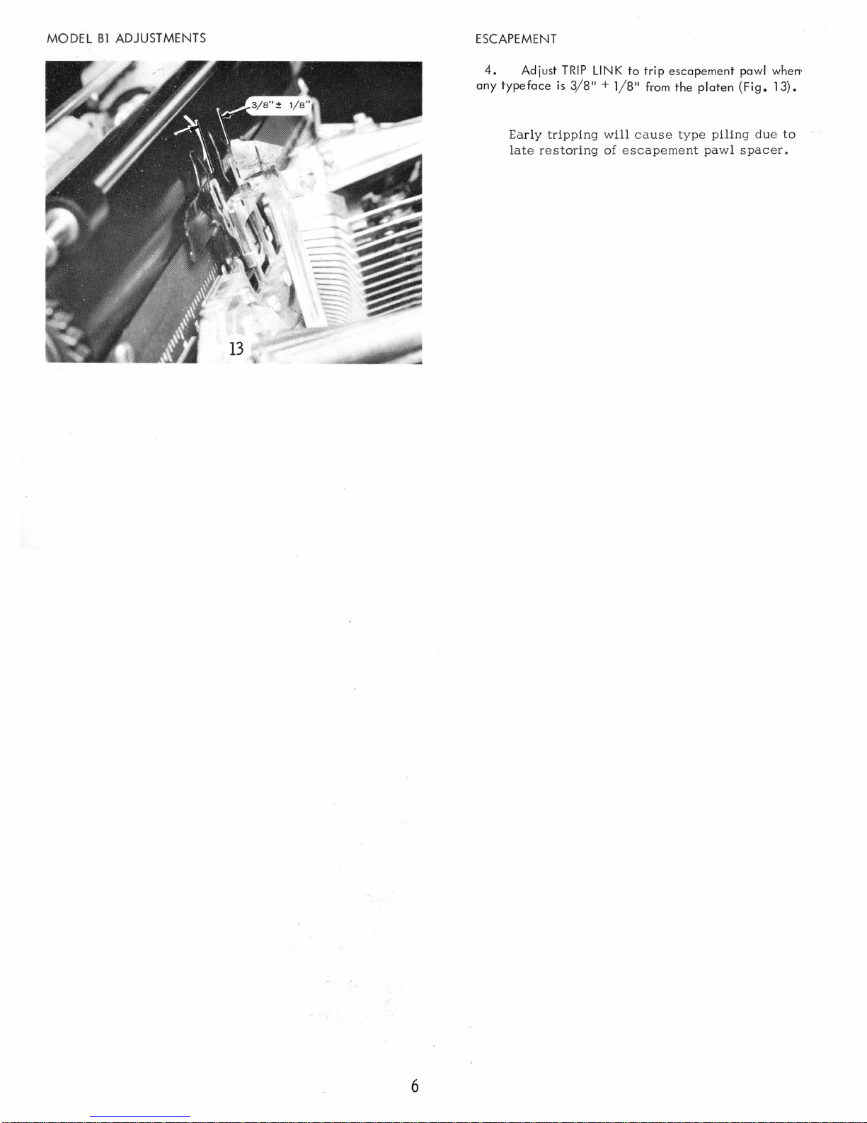
4.
Adjust
any
typeface
Early
tripping will
late
restoring
TRIP
is 3/8"
LINK
+ 1/
of
to
trip
escapement
8"
from
the
cause type
escapement
platen
piling
pawl
pawl wherl'
(Fig.
13).
due
to
spacer.
6
Page 10
KEYLEVERS
AND
CAMS
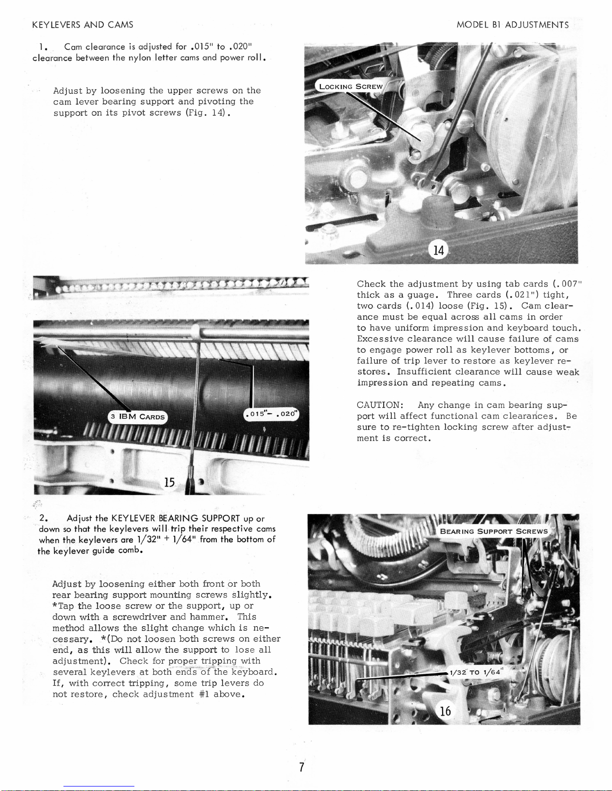
1.
Cam
clearance
is
adjusted
for
.015"
to
.020"
clearance
between
the
nylon
letter
cams
and
power
roll.
Adjust
by
loosening
the
upper
screws
on
the
cam
lever
bearing
support
and
pivoting
the
support
on
its
pivot
screws
(Fig.
14).
2.
Adjust
the
KEYLEVE,R BE-
ARINGSUPPORT
up
or
.
down
so
that
the
keylevers
will, trip
their
respective
cams
when
the
keylevers
are
1/32
11
+
1/64"
from
the
bottom
of
the
keylever
guide
comb.
Adjust
by
loosening
either
both
front
or
both
rear
bearing
support
mounting
screws
slightly.
*Tap
the
loose
screw
or
the
support,
up
or
down
with a screwdriver
and
hammer.
This
method
allows
the
slight
change
which
is
ne-
ces
sary.
* (Do
not
loosen
both
screws
on
either
end,
as
this
will
allow
the
support
to
lose
all
adjustment).
Check
for
proper
tripping
with
several
keylevers
at
both
end s
""-of;"";
the keyboard.
If,
with
correct
tripping,
some
trip
levers
do
not
restore,
check
adjustment
#1
above.
7
MODEL
B1
ADJUSTMENTS
Check
the
adjustment
by
using
tab
cards
(.007"
thick
as a guage.
Three
cards
(.
021")
tight,
two
cards
(.014)
loose
(Fig.
IS).
Cam
clear-
ance
must
be
equal
across
all
cams
in
order
to
have
uniform
impression
and
keyboard
touch.
Excessive
clearance
will
cause
failure
of
cams
to
engage
power
roll
as
keylever
bottoms,
or
failure
of
trip
lever
to
restore
as
key
lever
re-
stores.
Insufficient
clearance
will
cause
weak
impression
and
repeating
cams.
CAUTION: Any
change
in
cam
bearing
sup-
port
will
affect
functional
cam c leara11ces.
Be
sure
to
re-tighten
locking
screw
after
adjust-:-
ment
is
correct.
Page 11
MODE L
Bl
ADJUSTMENTS
KEYLEVERS
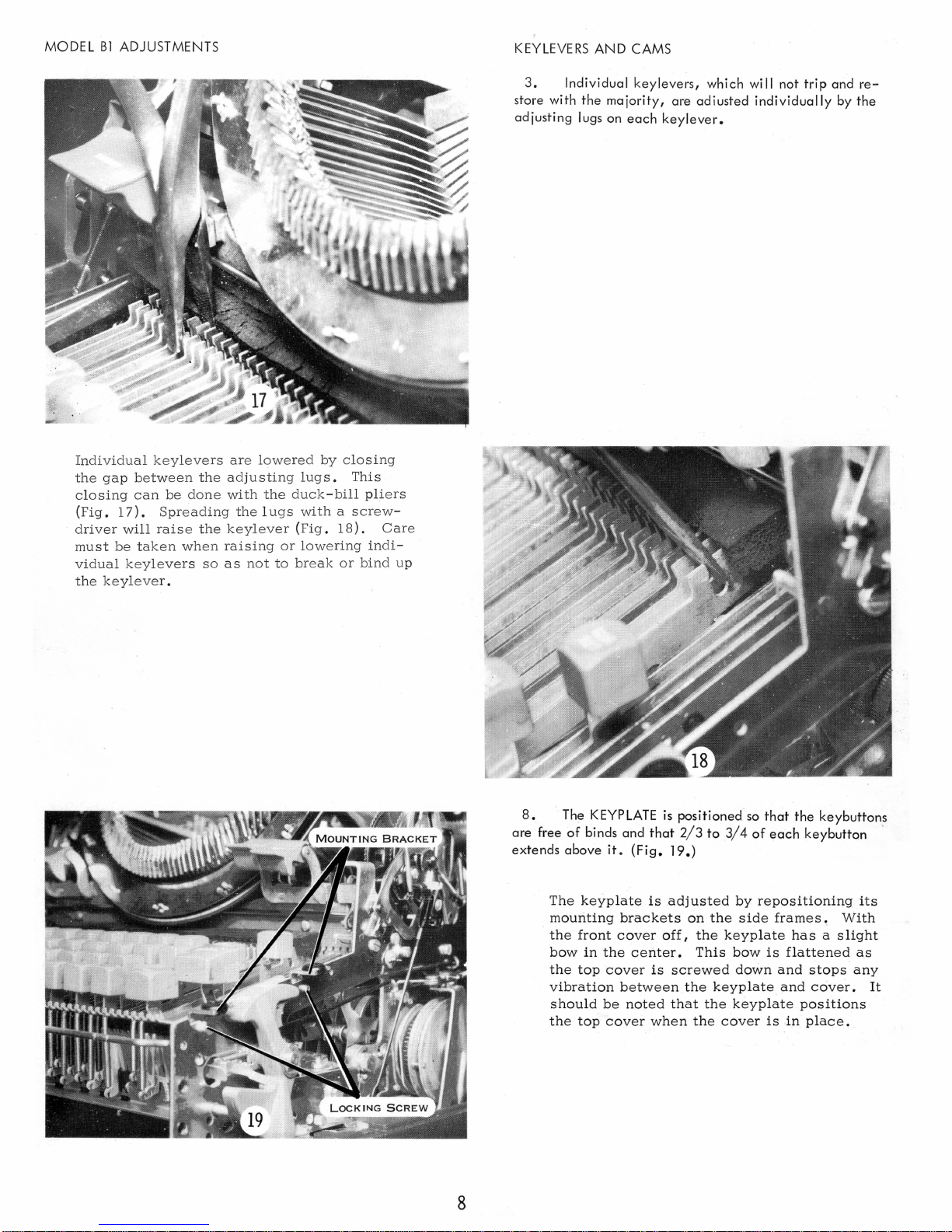
3.
AND CAMS
Ind
ividual
keylevers,
which will not
store with the majority, are adiusted
adjusting lugs on
each
keylever.
trip
individually
and re-
by the
Individual keylevers
t
he gap
closing
(Fi
driver will
mu
vidual
the
g.
17).
st
be taken
keylevers
keyleve
between
can
be
Spreading
raise the
r .
the adjustin
done
when rai
so
are
lowered
with
the
the 1 ugs with a screw
keylever
sing
as
not
by
closing
g l
ugs. This
duck-bill pliers
(Fig . 18) .
or
lowering indi-
to
break
or bin
-
Care
d up
8.
The
KEYPLATE
of
are free
binds and
extends above it .
The
keyplate
mounting
the
front
bow
in
the
the
top
cover
vibration
should
the
top
be
cover
that
(Fig.
is
brackets
cover
center.
is
between
noted
when
is
positioned
2/ 3
to
19.)
adjusted
on
off I the
This
screwed
the
that
the
the
so
3/4
of
by
the
side
keyplate
bow
down
keyplate
keyplate
cover
that
the
keybuttons
each
keybutton .
repositioning
frames ~ With
has a slight
is
flattened
and
stops
and
cover.
positions
is
in
place.
its
as
any
It
8
Page 12

CARRIAGE
1.
Adjust the
eliminate
verticle
PLATEN
movement
lATCH ECCENTRICS to just
of
the
platen.
(Fig.
20.)
MODEL
B1
ADJUSTMENTS
Loosen
attempting
w
writing
too
locking
ill
allow the platen
line.
tight.
nut
to
adjust· it.
Latches
on the
ecce
ntric before
Excessive clearance
to
mov e I
will
giving
work
hard
unev
if
adjusted
en
2.
Adjust
PLATEN
front to back movement
Some
machines will have locking scr
and
eccentrics;
With
both
types I lo
and
snug
adjust.
but eas
Correct
ily
CONTROL YOKES to remove
of
Platen.
others
osen the locking scr
re mov
(Fig.
21.)
only loc
adjustment ins
able platen.
kin
g s
ures
ews
crews.
ews
a
3.
Position
the
platen
adjusting
The
ward.
the
guide shaft
plates.
multiple
(Fig.
PLATEN
eccentrics
22.)
copy
control
RETAINING
tightly
lever
PLATES
to hold
against the platen
must
be
for-
9
Page 13

MODEL
Bl
ADJUSTMENTS
CARRIAGE
4.
Adjust RING AND
carriage
ing
and
eccentrics
CYLINDER
by
moving inner
platen front to rear with the ,platen adiu!;t-
(Fig. 23).
There
paper
the
proper
Check
plat
en
change
Be
fore
loosen
(Fig.
25)
screws.
should
as
be a slight
it
is
removed
position
this
adjustment
to
insure
across
the
adjusting
the
feed roll center
and
both
ring
the
rear
when
(Fig.
at
and
platen.
platen
platen
drag
on
the
24).
both
cylinder
adjusting
support
retaining
the
platen
ends
strip
of
will
eccentrics
screws
is
the
not
plate
of
in
I
Check
sheet
ribbon
in
a
the
I
RING AND CYLINDER
of
bond
paper
in
operating
lower
case
position
strip
of
bond
paper
ribbon
and
the
in
the
position.
against
used
sheet
with a single
machine I and
Hold a typebar
the
as a guage
of
bond
paper.
ring
the
with
between
10
5.
the
Adjust
eccentric
The
center
any
change
justment.
be
necessary
support
support.
Correct
relation
multiple
FEED
ROLL
CENTER
collar
on the platen guide shaft. (Fig.
supports
in
carriage
On
long
carriage
to
loosen
before
support
between
copy
adjusting
adjustment
platen
control
must
ring
is
SUPPORT
be
and
machines I it
the
margin
the
insures
and
feed
adjusted.
to just touch
readjusted
cylinder
rack
feed
roll
the
rolls
25.)
after
ad-
will
center
center
proper
as
the
Page 14
RAILS
10
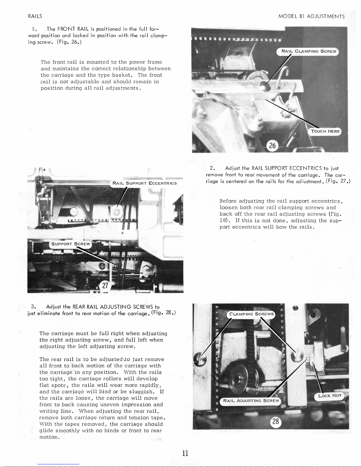
The FRONT
RAI L is
ward position and locked
ing
screw.
The
front
and
maintains
the
carriage
rail
is
position
(Fig.
not
during
26.)
rail
is
the
and
adjustable
all
positioned
in
position with
mounted
correct
the
type
and
rail
in
the
the
to
the
power
relationship
basket.
should
adjustments.
full
rai I
The
remain
for-
clamp-
frame
between
front
in
2.
Adjust the
remove front to
riage
is
centered
RAI L SUPPORT
rear
movement
on
the
rails for the
MODEL
Bl
ADJUSTMENTS
ECCENTRICS to just
of
the
carriage.
adjustment.
The
(Fig.
car-
27.)
3.
just
Adjust
eliminate
The
carriage
the
right
adjusting
The
rear
all
front
the
carriage
too
tight,
flat
spots,
and
the
the
rails
front
to
writing
remove
With
the
glide
smoothly
motion.
the
REAR
RAIL
ADJUSTING
front to rear motion
must
be
full
adjusting
the
rail
to
back
in
the
the
carriage
are
back
line.
both
carriage
tapes
left
adjusting
is
to
motion
any
carriage
rails
will
loose,
causing
When
removed,
with
screw I and
be
adjusted·.to
position.
will
bind
the
uneven
adjusting
return
no
of
right
of
the
rollers
wear
or
carriage
the
binds
SCREWS
the
carriage.
when
full
screw.
just
carriage
With
will
more
be
sluggish.
will
impression
the
rear
and
tension
carriage
or
front
(Fig.
adjusting
left
when
remove
with
the
rails
develop
rapidly,
move
rail,
tape.
should
to
rear
to
and
If
28.)
Before
loosen
back
28).
port
adjusting
both
off
the
If
this
eccentrics
rear
rear
is
the
rail
rail
not
will
rail
clamping
adjusting
done,
bow
support
screws
adjusting
the
rails.
eccentrics,
and
screws
the
(Fig.
sup-
11
Page 15

MODEL
The
by
necessary
contact
erated.
compensates
and
form
adjustment.
the
set
adjusted
set
hairpin
lever
Bl
ADJUSTMENTS
margin
the
stop
margin
to
the
right
This s light
the
margin
the
margin
mounting
lever
mounting s'crew
to
remove
lever
without
spring
(Fig.
29).
is
control
adjust
side
for
the
will
set
Move
screws
binding
must
spring
lever.
the
of
off
center
tension
set
accurately.
lever
the
bracket
(Ficj.
all
side
reliably
loaded
margin
the
notch
of
when
30).
and
movement
the
restore
to
the
Therefore,
set
lever
as
adjustment
the
margin
Do
making
after
loosening
The
margin
lock
nut
set
lever.
the
left
it
this
must
of
set
it
to
is
not
the
The
is
op-
stop
be
MARGIN
1.
lever
enters
resting
at
SET
Adjust
the
the
the
MARGIN
notch
in
left margin
SET
BRACKET
so
the margin stop with
(Fig.
29).
that
the
the
set
carriage
12
2.
Adjust
the
MARGIN
set lever just
clears
the
margin rack with
keybutton fully depressed •
.
If
the
margin
not
reliably
m~rgin
too
low,
as
the
set
tween
the
rack.
it
set
release
If
the
will
not
lever
margins.
SET
lever
the
margin
cam
is
incorrectly
LINK
is
set
margin
set
over'the
so
thatthe
the
too
high
stop
lever
margin
operated
margin
margin set
I
it
will
from
the
is
set
stop
be-
Page 16

MARGIN
1.
the margin control lever will
.010"
RELEASE
Adjust MARGIN
to 0015".
(Fig.
RELEASE
32.)
ECCENTRIC
clear
the margin rack
so
that
by
LINE
1.
crank
the arm
(Fi
g.
LOCK
The
is
adjusted
of
33.)
VERTICAL
so
that
the
lower bellcrank
LINK
the
MODEL
from
angle
81
the upper line lock
between
is
approximately
ADJUSTME.NTS
bell-
the
link and
90°.
2.
Adjust the
. ing manner:
a.
b.
c.
do
e.
f.
LINE
LOCK
PUSH
ROD
in the follow-
Unhook
Position
Push
rear
lock
Push
Push
Match
the hole in the lower line lock
the
push
rod.
the
carriage
the switch lever far enough to the
to
allow
the
the
key
lever.
down and hold a
forward on the push rod until it stops.
the
pin in the push rod clevis with
at
the right margin.
linelock
bracket
letter
keylever.
to
un-
bellcrank.
This
adjustment
transmitted
to
insures
line
lock
maximum
push
rod.
motion
This
adjustment
action
without
insures
choking
maximum
off.
locking
13
Page 17

MODEL
Bl
ADJUSTMENTS
PAPER
FEED
Too
much
decrease
to
the
Check
flector
clearance
their
rear
feed
adjusting
out.
tension
rolls.
plate
at
the
and
adjustment
front
add
feed
greater
with
rolls
tension
the
will
de-
1. Position the ADJUSTING
pressu
re
leve
are
inserted
the front feed rolls have a
platen.
rolls should be free to turn
rs (F ig. 35)
between
If
five
IBM
the r
cards
so
ear
are
PLATES
that
when two I
feed rolls and the
sl
ight
amount
inserted,
(Fig.
34).
on
the
rear
BM
cards
of
the front feed
platen,
drag on the
14
2.
Support LUGS.
levels
(Fig.
35)
so
• 030" (one to four I
and
the
platen.
Card
strips
deflector
check
flector
must
the
and
not
and
clearance
bind
Form
that
there
BM
cards) between
can
be
between
platen
the
(Fig. 3 6).
platen
the lugs on
is a clearance
inserted
feed
rolls
between
or
feed
at
the
the
the
The
the
rear
of
paper
ends
to
paper
deflector
rolls.
pressure
.oor to .
deflector
of
the
accurately
de-
Page 18
PAPER
FEED
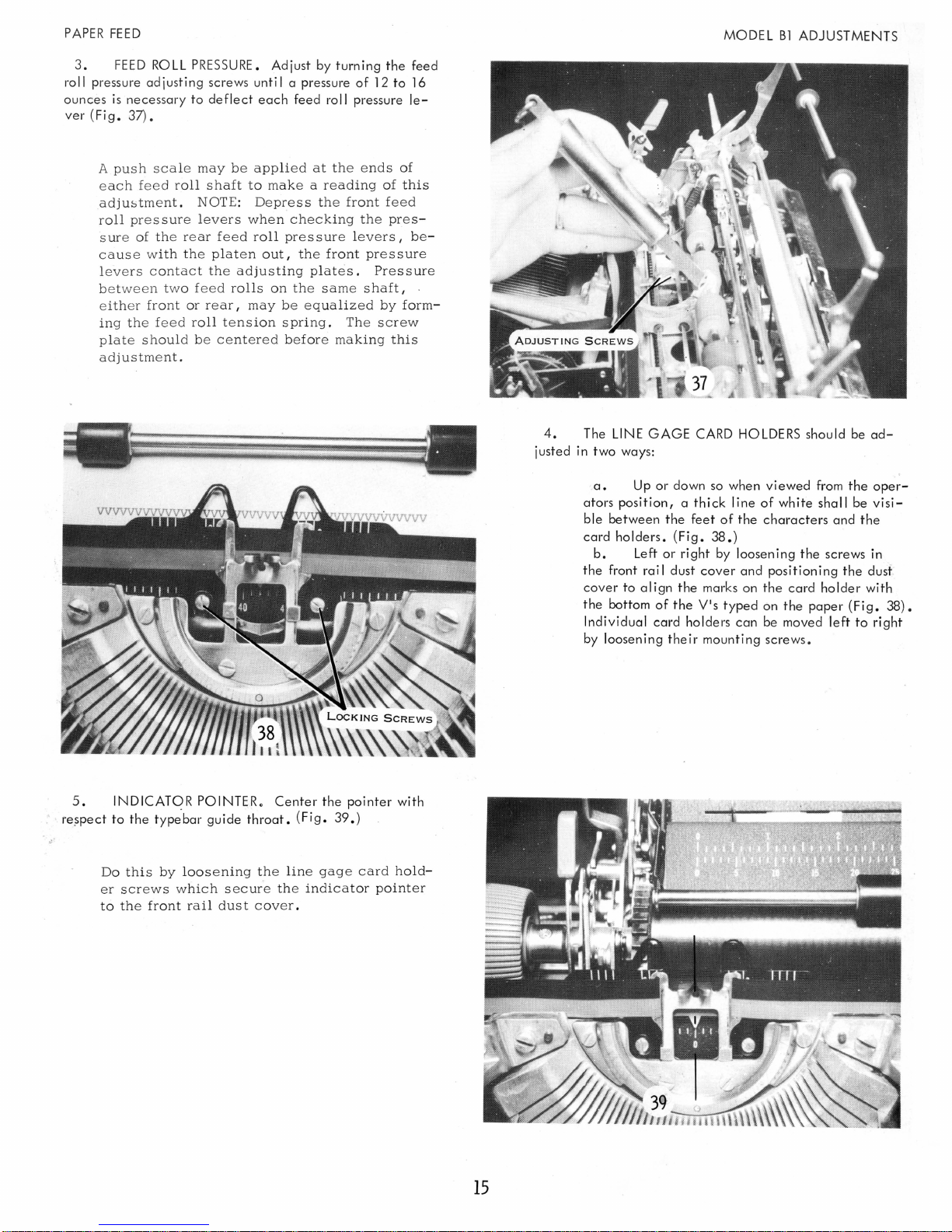
3.
FEED
r
oll
pressure
ounces
ver(Fig.37).
A
is
push
necessary
each
adjustmen
roll
s u
re
cause with
levers
bet
ween tw
e
ith
er fr
ing the f
pl
ate
adjustme
ROLL PRESSURE.
adjusting
to
sca
le
may
feed roll
pres
of the
shaft
t.
NO
sure levers
re
ar
the
c o
ntact
o f
eed rolls
ont
or rear I
eed
roll
should
be cent
nt.
Adjust
screws
until a pressure
deflect
plat
each
feed
be
applied
to
make
TE:
Depress the
whe n
checking
feed
roll
pre s sure lever
e n
out I the front pressure
the adjusting
on
the same
may
be equaliz
tension spring.
ered before making
by
turning
roll
at the
a r
eadi
front
plates.
The screw
the
of
12
pressure
ends
ng
of
feed
the
press I b
Pre
shaft
ed
by
thi
to
of
this
ssur
I
form-
feed
16
le-
e-
s
MODEL
B1
ADJUSTMENTS
e
4.
The
LINE
justed
in
two
GAGE
ways:
CARD HOLDERS
should
be
ad-
re?pect
~.
5.
INDICATOR
to
the
type'bar
Do
this by
er
screws which
to the
front
POINTER.
guide
throat.
loosening the
s e
cure the indicator
rail
dust
cover.
Center
(Fig.
line gage
the
pointer
39.)
card
pointer
with
hold-
a.
Up
ators
position, a thick
ble
between
card
holders.
b.
Left
the
front
cover
to
align
the
bottom
Individual
by
loosening
rail
card
or
of
down
the
(Fig.
or
dust
the
their
feet
right
cover
the
marks
ViS
holders
mounting
so
of
38.)
by
typed
when
line
viewed
of
white
the
characters
loosening
and
positioning
on
the
on
can
be
screws.
the
card
the
paper
moved
from
shall
and
screws
holder
left
the
be
the
(Fig.
the
to
oper-
visi-
in
dust
with
38).
right
15
Page 19

MODEL
7.
lationship
allow
the
catching
Bl
ADJUSTMENTS
REAR
PAPER TABLE.
between
paper
to
(Fig.
41).
the
pass
Adjust
deflector
freely
in
this
and
either
so
the
paper
direction
that
the
table
without
re-
wi
PAPER
FEED
6.
FRONT
manner:
Front
platen.
rear
II
a.
b.
c.
d.
as
shaft
(Fig. 40) .
zero
en
scal
paper
PAPER SCALE.
Loosen
the
collar
which
positions
Position
left
Move
Position
It
position.
the
with
the
e s
must rest
must
is
the
left
carriage
the
front
the
collar
also
inserted.
Adjust
in
the
on
the
platen
the
front
margin
indicator
screw (Fig. 39) .
evenly
be
to
the
paper
free to
stop
left
scale
pointer
across the
move
following
guide
paper
to
its
margin.
to
align
and
front
scale
extreme
the
tight-
to
This
clamp
bracket
Check
not
touching
is
adjusted
the
(Fig.
to
adjusting
42).
be
sure
the
by
the
locking
plates
that
the
deflector.
to
rear
screws
the
paper
paper
table
that
table
is
16
Page 20

PAPER
FEED
8.
FRONT
graduations
on
the
front
on
the
paper
PAPER
front
scale.
TABLE.
paper table
(Fig.
Adjust
43.)
are
this
in
so
that
line with
the
those
MODEL
Bl
ADJUSTMENTS
Adjust
on the
paper
table
its
by
carriage
table
to rest even
entire length.
forming the
riage
tie rod.
loosening
tie
(Fig.
44). Also adjust the
ly
stop
lugs which
the
rod
on
This
positioning
and
moving
the
platen
is
acc
omplish
contact
collars
the
rear
paper
throughout
ed
by
the
car-
17
Page 21

MODEL
Bl
ADJUSTMENTS
OPERATIONAL
CAMS
Operational
l
easing the
ing
the
position
respect
correct
rear h
th
lug
cams
e re l
by the
to
when
alf
ease lever
must
cam
cam with
the
the
of the
thickness
be
checked
®
clearance
of
the
cam
lug.
release
cam ,lug.
should. fall
is
checked
the
power
cam
release lever with
The adjustment
lever
On
the
behind
of the
on
lug.
both
ADJUSTABLE
off I and
rests
shift
~he
Double
lobes.
on
STOP
by
the
cam
SCRE
re-
not-
is
cam
lob
1. Adiust OPERATIONAL CAM
.010" to 0015"
Adjustable
operational
lock
45 I 46, and
The
of a stop
NOTE: All
a
W
I
ed
similar
ance.
will
CAM
from
stop
nut
before
ribbon
be
RELEASE
cam
screw.
operational
manner
Therefore I the
given
LEVER
the power roll 0
screws
cam
clearanc
adjusting
47) .
has
an
for
only
in
are
eccen
cams
the.
theory
this
CLEARANCE
used
e .
Be
sure
stop
screws.
tric
stop
are
adj
010"
to
of
adjustment
section.
to
change
usted
.015"
for
to
loo
(Fig.
instead
clear-
sen
in
\
~
CAM
LATCHED
~
CAM
~
®
Insufficient
cam
to
buzzing
duces
ride
sound.
the
cam
on
effective
RELEASE
clearance
the
power
Excessive
rise
SINGLE
LOBE
will
roll
clearance
of
the
CAM
and
ASSEMBLY
cause
make
cam.
the
re-
a
-'.
18
Page 22

BACKSPACE
1.
Adjust CAM
CLEARANCE
for 0010" to
.015"
0
(Fig.
48.)
Adjust CAM
RE
LEASE
LINK
so
the cam repeats when the
plugger
is
depressed
1/16".
(Repeat cam). (Fig.
50.)
19
MODEL
B1
ADJUSTMENTS
2.
Adjust the CAM
RELEASE
LINK
so
that
the cam
is
released when the
keylever
is
depressed 1/ 2 to
~/3
of
its
travel.
(Non-~epeat
cam). (Fig.
49.)
Page 23

MODEL
B1
ADJUSTMENTS
BACKSPACE
3.
Adjust the
the
interlock mounting bracket left to
BACKSPACE
INTERLOCK
right.
by forming
(Fig.
51.)
4.
Form
the
PAWL
the
interlock
at
rest, the backspace pawl will just
the interlock as the pawl
This
adjustment
RE
LEASE
is
operated.
insures
LEVE R LUG
(Fig.
positive
so
that
with
clear
52.)
interlocking.
Adjust
clears
clearance.
so
the
that
as
backspace
the
interlock
pawl
by a minimum
is
rotated
I
it
20
5.
Form
the
BACKSPACE
right
so
that
it
wi
II
guide the backspace pawl into the
rack with
the
1/64"
clearance
between the right surface of
pawl tooth and an escapement rack
Place
the
blade
of a screwdriver
forward
dri
ver
portion
with the
of
the
hammer.
PAWL
lug
GUIDE
and
tooth.
against
tap the
LUG
(Fig.
left or
53~)
the
screw-
Page 24

BACKSPACE
6.
Adjust
stop
the
pawl
for
the
escapement
the
escapement
the
BACKSPACE PAWL STOP so
just as
the
rack.
pawl
carriage
to
(Fig.
drop
54.)
has
into
moved
the
next
far
tooth
that
enough
it
on
will
The
the
stop.
pawl
stop
backspace
(F i
g.
is
pawl
55.)
also
adjusted
is
interlocked
MODEL
front
it
B1
ADJUSTMENTS
to
back
so
will
pass
that
behind
when
the
7.
be 1/4
is
stopped
Adjust
11
of
by
This
the
escapement
With
riage
an
extra
the
OPERATING
trave I left
its
stop.
1/4
travel
the
pawl
will
be
space.
on
the
(Fig.
holds
rack
so
locked
stopped
cam
56.)
the
and
and
LINK so
when
backspace
against
in
position,
will
that
the
not
there
backspace
pawl
its
stop.
the
coast
will
in
car-
back
pawl
Observe
of
the
power
be
stopped
into
the
this
machine.
roll
by
just
next
adjustme
Release
hand.
as
rack
tooth.
nt
The
the
escapement
through
the
cam
backspace
the
and
bottom
turn
pawl
pawl
the
must
clicks
21
Page 25

MODEL
Bl
ADJUSTMEN
TS
22
BACKSPACE
8.
Form
the
CARRIAGE
RETURN
TAB
INTERLOCK
EXTENSION
toward
the
front
of
the
machine
iust far
enough to
prevent
the
clutch
from
latching
during a
simul-
taneous backspace and
carriage
return
operation.
The clutch will
not
latch because the back-
sp
ac e
interlock will preve
nt the ca
rri
age
re-
turn
tab
interlock
from
rotating
as
sho
wn
(Fig.
57)
.
Page 26

SHIFT
Before
adjusting
the
shift
mechanism,
ring
and
cylinder
adjustments
must be
correct.
(See
Carriage
Adj.
#4)0
1.
Adjust
EVEN
TOP
AND
BOTTOM
of
the
lower
case
letters
by
screwing
the
shift
stop
screws
up
and
down.
(Fig.
58.)
Loosen
lock
nuts
and
adjust
both
stop
screws.
The
heads
of
the
stop
screws
must
rest
with
equal
pressure
against
the
stop
washers.
Equal
pres
sure
is
checked
by
placing a nar-
row
strip
of
paper
between
the
stop
washer
and
the
stop
bracket.
Slowly
pull
the
paper
out
and
note
the
amount
of
drag.
Check
both
sides
for
equal
drag.
Unequal
pres
sure
will
bend
or
break
the
stop
bracket
that
is
being
used.
Be
sure
to
retighten
the
lock
nuts.
3.
Adjust
CAM
CLEARANCE
FOR.
010"
to
.015"
(Fig.
60).
4.
Adjust
CAM
RELEASE
LINK so
that
cam
will
be
released
when
keylever
is
depressed
1/2
to
3/4
of
its
total
travel.
23
MOD
EL
Bl
ADJUSTMENTS
2.
Adjust
SHIFT
MOTION
by
moving
the
lock
nuts
on
each
stop
screw
so
that
the
upper
case
characters
print
on
the
same
line
as
the
lower
case
characters.
(Fig.
59.)
The
lock
nuts
must
also
rest
with
equal
pres-
sure
on
the
stop
bracket.
Be
careful
not·to
turn
the
stop
screws
when
adjusting
the
stop
nuts.
Page 27

MODEL
Equal
ing
B1
ADJUSTMENTS
pin
clearance
manner:
is
checked
in
the
follow-
SHIFT
5.
Adiust
toggle brackets
(Fig. 61).
EQUAL
PIN
CLEARANCE
up
or down with the toggle bracket screws
by
moving the
a.
b.
c.
d.
With
lower
Depress
the
pusher
62) .
Place
Release
to
lower
power
case.
shift
basket
key
pin
OFF I
keylever
to
upper
down
lever
clearance
place
pin
in
and
basket
and
clearance
upper
observe
(Fig.
up
observe
case.
pusher
63) .
in
(Fig.
The
for
both
ance
it
is
To
adjust
upper
lower
Use
ance.
to
vary
lo
wer
pusher
positions.
at
this
equal
toggle
screws
the
converse
Unequal
in
case
to
point
(Fig.
equal
bracket
speed
(Fig.
pin
clearance
The
is
not
62 &
63).
pin
clearance I loosen
screws
to
reduce
to
reduce
pin
clearance
and
action
61).
must
amount
important
and
lower
upper
between
be
of
tighten
pin
clearance.
will
the
pin
as
pin
cause
upper
clear-
long
both
c l
ear-
same
as
both
shift
and
24
Page 28

SHIFT
6.
Adjust
pusher wil l be
upper pin when
This
adj
Slowly
s
erv
ing
as
the
cam
the pusher
the
PUSHER
even
the
ustment
depress
the
rising
operates
as
cam
LINK
with or slightly above the
is
released
is
checked
the
shift
pusher.
and
it contacts
so
that
the
top
of
the
top
of
(Fig.
64A.)
with
the
power
keybutton while ob-
Continue
note
the
with the
to
position
pin.
observe
the
ON.
of
7.
Adjust the OPERATING
clears
the pin by 1/ 32" to 1/ 16" ,
MODEL
LINK
(Fig.
B1
ADJUSTMENTS
so
that
the pusher
64B.)
8
Adjust
0
is
released just as
Check
buttons.
when
the
SHIFT
the
lock
for
easy
unlocking
Loos
en
adjusting the
LOCK
engages.
locking
bracket.
BRACKET
(Fig.
with
stud
only
so
65.)
both
that
the
shift
slightly
cam
key-
The
shift
as
the
shift
operating
e
r.
Insuffici
the
pusher
on
shift
due
to
too
Excessive
due
to
too
due
to
pusher
e
nough.
buffer
ent
keybutton
is
mounted
pusher
link
pusher
to
much
c l
earance
little buffer action
and
will effect
to
bind
on
or
buffer
can
not
rot
ating
pin
pin, giving
hesitating
to
the
same
a ny adju
both
clearance
action.
cause a noisy shift
or
toggle
stment
buffer
heavy
shift
shift
plate
and
can
action
failur
stud
of
cause
touch
far
the
push
e
-
25
Page 29

MODEL
Bl
ADJUSTMENTS
TABULATION
3.
;0
.
01
40
0002
tab
TAB
that
011
LEVER
the margin control
to .
01
511• ( Fig.
Adjust the
11
stop
to
.015
and
~
11
HEIGHT. Adjust the margin
TAB
clearance
engaging
lever
67.)
RACK
between
face
will
clearthe
left or right
the
left face
of
the
tab
release
margin rack by
so
that
there
of
lever
(Fig.
any
68).
eccentric
is
set
-
1.
Adjust CAM CLEARANCE for
(Fig.
66.)
2.
released
trave
I.
Adjust CAM
when
the
RELEASE
keylever
11
.010
to
.01511•
LINK <so
is
depr~ssed
that
2/3
the
cam
of
is
its
8
____
_
26
Check
tab
lever
held
of
the
lever
(Fig.
This
be
in
by
the
every
can
cause
tab
stop.
Be
sure
same
and
this
adjustment
to
as
the
escapement
just
past
68)
observe
adjustment
the
proper
check
other
carriage
to
adjust
amount
plates.
the
rear.
escapement
rack.
the
front
t1:1e
insures
position
lever.
tab
stop.
to
both
to
prevent
by
slowly
The
pawl
With
edge
.002"
that
when
It
also
Excessive
stop
ends
bowing
carriage
will
the
of
the
to ~ 01
the
it
allows
one
space
of
the
the
moving
must
be
held
tab
check
tab
S" .
ca-rriage
is
stopped
tabbing
clearance
past
tab
rack
carriage
the
be
out
stop
will
to
the
the
Page 30

o TABULATION
5.
Ad
just the
TAB
RACK
PARALLE
L to
the
rear rai I
and the front
of
a set
tab
stop
parallel
with
the
tip
of
the
check
lever.
(Fig.
69.)
Adjust
by
moving
the
right
-
end
of
the
tab
rack
front
to
rear
in
its
elongated
mounting
hole.
Check
this
adjustment
by
noting
the
tab
check
lever
bite
on
extreme
left
and
right
tab
stops.
Maintain
the
set
tab
stops
parallel
with
the
check
lever
when
tightening
the
lock
nuts.
/
Insufficient
latch
overthrow
on
the
keeper
can
cause
the
carriage
to
stop
one
space
too
soon
or
be
stopped
by
the
escapement
pawl
due
to
early
tab
unlatching.
o
Excessive
overthrow
of
the
latch
CAN
cause
failure
of
tab
to
unlatch
or a bouncing
sound
as
the
check
lever
stops
the
carriage
.
...fA.
correctly
adjusted
and
operating
tab
will
have
a
single
solid
sound
as
the
carriage
comes
to
rest
at
the
tab
stop.
27
MODEL
B1
ADJUSTMENTS
6.
Adjust
the
TAB
LATCH
KEEPER
front to back
so
that
when lat,
ched,
the
check
lever overlaps 1/ 2
to
2/ 3
of
a set
tab
stop
(Fi
g.
71).
Ad
iust
the
keeper
left
to
ri
ght
so
that
there
is
.030"
to
.050"
overlap
of
the
tab
latch
on
the
keeper
(Fig.
70).
This
adjustment
is
checked
by
latching
the
tab
lever
by
hand
and
hoiding
the
carriage
so
that a set
tab
stop
just
contacts
the
check
lever.
In
this
position,
both
adjustments
can
be
checked.
Page 31

MODEL
Bl
ADJUSTMENTS
8.
Adjust
PAWL CLEARANCE
by
forming
the
rear
upri
ght
I ug
of
the
pawl re
lease
lever
unti I
the
escapement
pawl
clears
the
esc.apement
rack
by
1/64"
with
the
tab
lever
latched.
(Fig.
73)
CAUTION:
Do
not
form
the
hook
on
the
tab
lever.
Form
only
the
pawl
release
lever
lug.
Check
the
1/64
clearance
by
latching
out
the
tab
h~ver
and
while
holding
the
carriage I sight
down
the
escapement
rack.
Excessive
clearance
can
cause
late
restoring
of
the
escapement
pawl
and
incorrect
tabulation.
28
TABULATION
7.
Adjust
the
TAB
OPERATING
LINK so
that with
the
cam
on
its
high
point,
there
is
.010"
to
.015"
clear
-
ance
between
the
tab
latch
and
the
keeper.
(Fig.
72.)
Check
this
adjustment
with
the
power
OFF.
Release
the
tab
cam
and
turn
power
roll
by
hand
until
cam
reaches
its
high
point.
Ob-
serve • 010"
to . 015"
overthro
w . The
ope
r-
ating
link
must
not
prevent
tab
lever
from re-
storing
against
the
rear
rail.
Be
sure
the
over-
throw
stop
does
not
limit
the
travel
of
the t
ab
lever
under
hand
operation.
Excessi
ve over
-
throw
can
cause
the
tab
check lever
to
strike
the
tab
rack.
Insufficient
overthrow can
cause
failure
of
the
tab
lever
to
latch.
9.
The REBOUND CHECK
BRACKET
is
adiusted
two
ways:
Position
the
bracket
left
or
ri
ght
so
that
the
ri
ght
edge
of
the
V-slot
of
the
rebound
check
lever
clears
the
right
hand
of
any
set
tab
stop
by
.010"
to
.018"
when
the
left
hand
face
of
the
stop
has pushed
the
tab
check
lever
to
the
extreme
left.
At
the
same
time,
the
bracket
should
be
positioned
front
or
rear
so
that,
when
the
rebound
check
lever
in its
operated
position
against
the
pin in its
bracket,
the
leading
edge
of
the
rebound
check
lever
is
even
with
the
tip
of
the
tab
check
lever
or
is
.005"
farther
to
the
rear.
The .
bracket
;an
be
conven i ent
I y
ad
i usted
for both
conditio~s
simultaneouslyo
Page 32

TABULATION
MODEL
Bl
ADJUSTMENTS
This adjust
l
easi
until
the
carriage
the check leve
c a n now be
ad
just
Excessive clearance will
to rebound and
th
e t
ab
ve
nt
ca
rriage lock-
ment
is most
ng the
the
tab lever from res
tab
cam I rotating
cam
is
on
its
to res
t w
r.
The rebound
loosened
ment (Fig. 74).
c o
me
stop.
Insufficient
up.
ith a tab
and
to
toring
rapidly
high
point
position
all
ow the
rest one
clearanc
made
the
power
I a
llowing
stop
agai
check
ed
carriage
space before
e c a n pre-
and res
ulting
by
re-
roll
nst
bracket
in correct
in
10.
Adjust the
is.OO5"
clearance
lug on the rebound
point. (Fig.
75.
)
TAB
LEVER
EXTENSION
so
that
there
between the extension and the upri ght
check
bracket
with
the
cam
on
its high
11.
Form
the
TAB
LEVER
LEAF
SPRING
tacts
the upri
at
rest.
(Fig.
ghtstud
76.)
on
the
rebound
check
so
that
with a
it
II
con-
parts
29
Page 33

MODEL
B1
ADJUSTMENTS
130 Position
the
TAB
SET
AND
CLEAR BRACKET r
ight
or
left
unti I the
tab
set
lever
strikes
the
center
of
the
back
of
the
tab
stop
which
is
second
to
the
left
of
the
tip
of
the
tab
check
lever.
(Fig.
78.)
Form
the
TAB
SET
AND
CLEAR
STOPS
so
that
the
levers
wi
II
clear
set
and
cleared
stops
by 1/32" with
the
levers
at
rest.
Loos
en
thr
ee
mounting scre
ws before position-
ing.
TABULATION
12.
CENTRIFUGAL
TAB
GOVERNOR
a.
Position
the
governor
by
means
of
its
mounting
screws
for a
maximum
of
.005"
backlash
between
the
pinion
gear
and
the
main
spring
drum
gea
ro
Check
full
length
of
the
carriage
-.
(Fig.
77.)
b.
Adjust
the
collar
on
the
governor
shaft
for
.003"
to
.005"
end
play
in
the
shaft.
c.
Speed
of
the
carriage
on
tabulation
is
adjusted
by
moving
the
governor
arm
spring.
Move
the
spring
closer
to
the
governor
arm
pivots
for
more
governor
action.
Move
the
spring away
from
the
pivots
for
less
governor
action.
(This
spring
must
be
in a correspond-
ing
hole
in
each
governor
arm) .
14.
Adjust
the
TAB
SET
AND
CLEAR LINKS so
that
-\,
when
the
set
and c lear
buttons
are
at
rest,
the
slope
of
the
i r
surfaces
wi
II
be
para
lie I to
the s lope
of
the
keyboard.
(Fig.
79.)
Page 34

TABULATION
150
Adjust the FRICTION GOVERNOR
PRESSURE
by
means
of
the two lock nuts on the hub
of
the main spring
drum until the speed
of
tabulation
approximates
the
speed
of
carriage
return.
(Fig.
80.)
Check
the
speed
by
clearing
all
tab
stops
ex-
cept
the
last
one
on
the
right.
Operate
the
car-
riage
return
and
tab . several
times
to
determine
this
speed.
16.
Adjust the
TAB
GOVERNOR
PAWL
LINK
so
that
when the
tab
lever
is
latched,
the governor pawl
wi
II
en-
gage the
fri
ction
plate
by
the thi ckness
of
the
pawl.
(Fig.
80.)
MODEL
B1
ADJUSTMENTS
31
Page 35

MODEL
B1
ADJUSTMENTS
CARRIAGE
RETURN
3. Adjust
the cam
on
clutch latch
FRONT
its high point, the clutch lever will
by
.020
CLUTCH
11
to
.025
LEVER
11
• (Fig.
LINK
82.)
so
that
clear
with
the
1.
2.
Ad
just CAM
(Fig.
81.)
Adjust CAM
peat
when the plunger
Fig.
50).
The
release
the
keylever
lever.
CLEARANCE
RELEASE
link
and
LINK
should
lower
for
so
is
depressed
be
hole
.010"
to
the cam will
1/16
in
the
rear
in
the
release
.015
11
hole
11
re-
(See
•
in
This
latched
overthrow
position.
allows
the
latch
to
rotate
to
its
4.
Adjust the
slot
in
the clutch lever bellcrank
rail,
with all parts at
in
outer hole
the
5. Adjust the
in
the clutch latch
The
link should
crank.
(Fig.
be
83.)
REAR
CLUTCH
rest.
bellcrank.
CLUTCH
be
I !crank
placed
in
.,
LEVER
LINK
is
parallel to the rear
The link should
(Fig.
83.)
LATCH
LINK
is
para lie I to the rear rai I.
the
center
be
so
that the slot
hole
of
so
that the,
in
the
the
bell-
32
All
parts
against
must
the
be
clutch
at
rest with
lever.
the
latch
resting
Page 36

CARRIAGE
RETURN
6.
OVERBANK
is
the amount
of
play
between
the
margin control lever and its final stop when
the
carriage
is
resting
at
the left
margin.
Place
the
carriage
one
space
from
the
left
margin.
Slowly
move
the
carriage
to
the
right
and
listen
that
the
escapement
pawl
drops
into
an
escapement
rack tooth
just
as
the
margin
control lever
strik
es
its
final
stop
(Fig.
84).
Excessive
overbank
can
cause
carriage
to
re-
turn
one
space
to
far.
Insufficient
overbank
may
prevent
carriage
from
returning
to
margin.
Adjust
both
ends
of
margin
rack.
Do
not
bow
the
carriage end
plates.
8.
Adjust
the
PAWL
RELEASE
LEVER
ECCENTRIC
so
that
the right side
of
the
ear
on
the
pawl release
lever
lust
clears
the
intermediate
pawl release lever when
all
parts
are
at
rest.
(Fig.
86.)
Keep
the
high
point
of
the
eccentric
toward
the
front
of
the
machine.
33
MODEL
Bl
ADJUSTMENTS
7.
Form
the
INTERMEDIATE
PAWL
RELEASE
LEVER
IPRIGHT
LUG
to
allow
the
intermediate
pawl release
;ver
to touch both
the
margin control
be
Ilcrank and pawl
; lease be Ilcrank when
the
carriage
is
one
space
from
the
~ft
rna
rgin 0
(Fig.
85.)
This
adjustment
insures
the
escapement
pawl
will
not
be released
from the
rack
when the
carriage
is
within
one
space
of
the
margin
and
"lill
remain
in
the
rack
during
repeat
line space.
Page 37
MODEL Bl ADJUSTMENTS
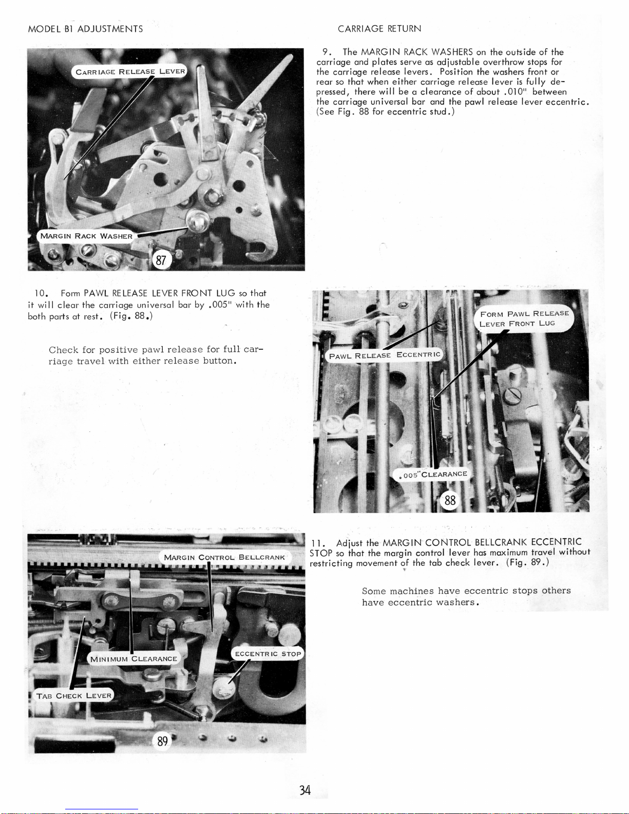
10.
Form
PAWL
RELEASE
it
wi
II
clear
the
carriage
both parts
at
rest.
(Fig.
88.)
LEVER
universal
FRONT
bar
by
LUG
.005"
so
'with
that
the
CARRIAGE
9.
The MARGIN
carriage
the
carriage
rear
so
pressed,
the
carriage
(
See
Fig.
and
that
there
plates
release
when
universal
88 for
RETURN
RACK
serve
levers.
either
will
be a clearance
bar
eccentric
WASHERS
as
adjustable
Position
carriage
and
stud.)
release
the
on
the
overthrow
the
washers front or
lever
of
about
pawl
release
outside
is
fully
.010"
lever
of
the
stops for
de-
between
eccentric.
Check
ri
age trave
for
positi
ve pawl re leas e
l w
ith eith
er release
for
full
car-
button.
--~
11. Ad-just the MARGIN '
so
that
STOP
restricting
the
movement
..
Some
have eccentric
of
the
CONTROL
tab
have
washers.
margin control
machines
BELlCRANK ECCENTRIC
lever
has maximum
check
lever.
eccentric
(Fig.
stops
travel
89.)
others
without
34
Page 38

CARRIAGE
12.
Adjust the CARRIAGE "
as follows:
RETURN
(Fig.
90.)
RETURN
TAB
INTERLOCK
MODEL
B1
ADJUSTMENTS
a.
b.
c.
This
be
unlatched
Unhook -the
clutch
Turn the high point
centri c stop to the rear
a pre
I iminary ad justment.
With the
carriage
the interlock
stud by about
lug on the
interlock
the margin control
adjustment
insures
when
the tab
so
1/16
un
latching
of
at
the
that
it clears the
11
when the
is
be
Ilcrank.
carriage
is
link.
the interlock
of
the
mach i ne as
left margin,
tab
left-hand
in
contact
with
return
operated.
ec-
will
form
latch
13.
Adjust the
the
clutch
unlatches when
margin control lever
(Fig.
91.)
Check
this
while depressing the
with
the
power
to
approach
gin
control lever
The
clutch
to
pull
until
1/
32"
to 1/64"
CLUTCH
-UNLATCHING
the
11
1/64
adjustment
ON.
the
left
as
should
the
r~main
margin
of
the
carriage
to
1/32
by
carriage
Slowly
margin.
it
nears
stop.
11
from
holding
allow
latched
control
LINK
has pushed the
its final
the
carriage
return
Observe
its
the
final
and
lever
button
carriage
the
stop.
continue
comes
so
that
stop.
mar-
to
'
14.
Adjust the
ECCENTRIC STOP
gates the
surface.
clutch
(See adjustment #12 for
stop.
15.
Adjust the
clutch
latched,
ment rack
the escapement pawl
by
1/64
lease link).
CARRI,AGE
(Fig. 90)
lever
by
PAWL
11
• (See Fig.
RETURN
so
that
1/3
to 1/ 2
RELEASE
83
TAB
the
clutch
of
the
pidure
LINK
so
wi
II
for picture
INTERLOCK
latch
clutch
of
eccentric
that
with the
clear
the
of
pawl
en-
latch
escape-
re-
Excessive
to
stop
clearance
one
space
can
.fro-m
cause
margin.
the
carriage
35
Page 39

MODEL
B1
ADJUSTMENTS
CARRIAGE
RETURN
With
the
clutch
lever
by
hand
erate
the
carriage
serve
that
the
not
strike the re
Form
the
top
of
to
provide a clearance
unlatched I operate
to
observe
return
rebound
bound
the
this
cam
check
check
interlo::::k
of
about.
the tab
adjustment.
by
hand
interlock
lever
at
lever
front
010"
and
does
rest.
to
: .
(Fig.
Op'-
ob-
rear
94.)
160 The REBOUND CHECK INTERLOCK LINK
justed
so
that
the
check
is
in its
lever by
operated
interlock
about.
position.
01
a"
lever
when
(Fig.
clears
the
93.)
the
tab
rebound
is
rebound
check
ad-
lever
This
the
riage
adj
us
rebound
return
tment
check
is
prevents
remains
operated.
carriage
to
the
!ock-
rear
up
and
if
car-
17.
Adjust the CLUTCH
the
clutch
earance
clutch
disc.
lever
plate
a
cI
the
friction
bracket
of . 01
with the
(Fig.
a"
95.)
to
PLATE
on
the
.015"
clutch
CLEARANCE by positioning
side
frame
(Fig.
97).
between
plate
the
operating
held tight
Obtain
arm and
against
the
Page 40

CARRIAGE
RETURN
18.
Position
AIR
CYLINDER front to rear on
the
side
frame to permit
the
plunger to move freely
(Fig.
96)0
190 AIR
CYLINDER
PARTS
AND
CLUTCH
COMPRES-
SION
ADJUSTMENTS should be considered
together.
The
air
cylinder
must reduce
the
impact
of
the
carriage
re-
turn as much as necessary without
noticeably
reducing
speed.
The intake port
on the
air
cylinder
shell
(Fig.
98) should
be
adjusted
approximately
half-
way ope
n.
Adjust
the
exhaust
port
so
that
the
shock
of
carriage
return
is
reduced
without
noticeably
slowing
the
carriage
during
the
last
half-inch
of
travel.
Test
this
action
on
short,
medium
and
full-length
returns
for
positive
and
quiet
operation.
If
an
operator
finds
excessive
resistance
in
pushing
the
carriage
back
to
the
margin,
re-
check
the
air
cylinder
ports.
It
may
be
ad-
vantageous
to
open
the
exhaust
port
slightly.
37
MODEL
Bl
ADJUSTMENTS
Open
the
exhaust
port
on
the
air
cylinder
cover
(Fig.
96).
With
the
line space
lever
set
for
triple
spacing
and
the
left
margin
stop
moved
to
the extr
eme left,
adjust
the
clutch
com-
pression
spring
to
insur
e a
positive
return
on
short
returns
of
one
to
two
inches
as
well
as
on
medium
and
long
returns.
Lack
of
sufficient
tension
can
contribute
to a slow
carriage
re-
turn.
(Fig.
97.)
The
compression
spring
must
be
adjusted
so
that
if
the
carriage
is
stopped
and held
during
a
return,
it
will
give a positive
return
when
the
carriage
is
released.
The
clutch
must
slip
and
not
stall
the
motor
if
the
carriage
is
held
during
carriage
return.
Page 41

MODEL
Bl
ADJUSTMENTS
CARRIAGE
RETURN
2Gl. The
LOWER
INDEX PAWL STOP
stop the downward movement
the
detent
roller
is
when
the
platen
Check
tape until the
st
sh
e
ith
ratchet. (Fig.
this
op. The n slowly re l
ould be
no
er fo:-ward
positioned
by pulli
ind
furthe
or
99.)
ex
backward
of
ng
on
paw
ax the t e
r rota
the
line
between
the carri
l s
tri
tion
.
is
adiusted
space
mechanism
two
teeth
age return
kes the lowe
nsion. There
of the
platen
to
on
r
I
38
Page 42
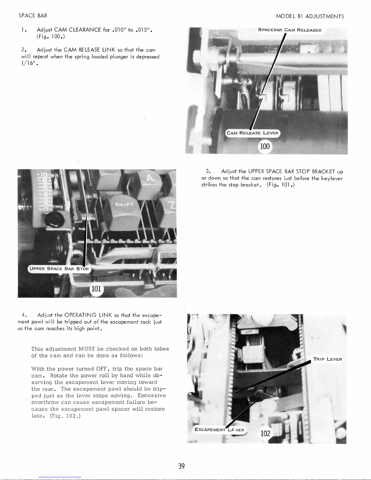
SPACE
BAR
MODEL
Bl
ADJUSTMENTS
1.
Adjust CAM CLEARANCE for
(Fi
g.
100.)
2.
Adjust the CAM
wi
II
repeat
when the spri ng loaded p I unger
1/16" •
RELEASE
LINK
.010
so
11
to
that
is
11
.015
•
the cam
depressed
3.
Adjust the
or
down
so
that
strikes the stop
UPPER
SPACE
the
cam restores just before the
bracket.
(Fig.
BAR
101.)
STOP
BRACKET
keylever
up
4.
Adjust
the
OPERATING
ment pawl
wi
II
be
tripped out
as the cam reaches its high
This
adjustment
of
the
cam
Wi
th
the
power
cam.
serving
Rotate
the
the rear.
ped
just
as
. over
throw can
cause
lat
e .
the
(Fig.
MUST
and
can
turned
the
power
escapement
The
escapement
the
lever
cause
escapement pawl
102.)
LINK
so
that
of
the escapement rack just
point.
be
checked
be
done
as
follows:
OFF I
trip
the s pace
roll
by
hand
lever
moving
pawl
should
stops
moving.
escapement
spacer
the
on
while
toward
Excessive
failure
will
escape-
both
be
be-
restore
lobes
bar
ob-
trip-
39
TRIP
LEVER
Page 43

MODEL
B1
ADJUSTMENTS
RIBBON
2.
bon
from
Adjust the CAM
cam
is
released when any typeface
the
platen.
The cam
the
ribbon
A
variation
bars
bon
able.
(Fig. 104.)
release link
lift
bail
in
the
may
be
caused
lift
bail. A variation
RELEASE
is
is
rotated
tripping
by a bent
LINK
so
is
more
accessible if
down
point
or
of
1/4"
that the
3/ 4" ±
(Fig.
between
curved
is
accept-
rib-
1/8"
105).
type
rib-
1. Adjust CAM
CLEARANCE
for .010" to
.015".
(Fig. 103.)
This
adjustment
centric
The
power
-
stud
roll
stop
and
after
nut
pulley.
is
made
loosening
can
be
by
rotating
the
reached
the
lock
through
ec-
nut.
the
40
Page 44
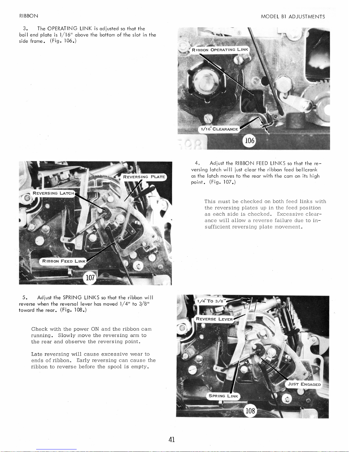
RIBBON
3.
The OPERATING
LINK
is
adjusted
so
that
the
bai I end
plate
is
1/16
11
above the bottom
of
the
slot
in
the
side frame.
(F i g.
1
06.
)
5.
Adjust the SPRING LINKS
so
that
the
ribbon will
reverse when the reversal
lever
has moved 1/ 4
11
to
3/8
11
toward the
rear.
(Fig.
108.)
Check
with
the
power
ON
and
the
ribbon
cam
running.
Slowly
move
the
reversing
arm
to
the
rear
and
observe
the
reversing
point.
Late
reversing
will
cause
excessive
we
ar
to
ends
of
ribbon.
Early
reversing
can
cause
the
ribbon
to
reverse
before
the
spool
is
empty.
41
MODEL
B1
ADJUSTMENTS
40
Adjust the
RIBBON
FEED
LINKS
so
that
the
re-
versing latch will just
clear
the ribbon feed bellcrank
as the latch moves to
the
rear with
the
cam
on
its high
point.
(Fig.
107.)
Thi
s m
ust
be checked
on
both feed lin
ks with
the revers
ing
plates
up
in the
feed
position
as each
side
is checked . Exc essive c lear-
a
nc
e w
ill
allo
w a reve
rse
failure
due
to
in-
s
uffi
c i e
nt
revers
ing
plate
mov
eme
nt.
Page 45

MODEL
B1
ADJUSTMENTS
RIBBON
6.
rests
half-way
Adjust
the
CHECK
between two
PAWLS
teeth.
so
that
(Fig.
the
feed pawl
109.)
7.
Adjust
so
that
the
the feed and
so
that
they
The
ribbon
the retaining
the
teeth
check
RIBBON
on
the
pawls.
SPOOL RETAINING SPRINGS
ribbon spool rides in
Form
cause a slight drag to
spool
plate
spring
screws.
the springs left
the
spools.
must
be
removed
the
center
to
(Fig.
right
110.)
to
of
loosen
Retighten the lock
adj
ust
when
feed
Two
a
spool
ment.
properly
at
tooth feed
each
stroke.
empties.
The
adjusted I provide
insur
ing
screw
ribbon
es
feed
rapid
after
making
mechanism
a tw
reversing
the
shall,
o-tooth
whe
n
42
Page 46

RIBBON
LIFT
10
Adjust the
RIBBON
LIFT
BAIL
ASSEMBLY
by
the
support screws
so
that there
is
0005" to 0015" end play o
(Fig. 111.)
3.
Adjust the
RIBBON
CENTER
GUIDE
CLEVIS
so
that
the top of the ta lIest characters strike 1/ 32"
be
low
the upper edge of the ribbon (Fig. 115).
Check
this
adjustment
by
typing
several
tall
characters
and
noting
on
the
ribbon where
the
.
type
face
struck.
The
lift
mechanism
should
be
set
in
the
first
lift
or
back
position.
Check
at
"0"
through" 1 A"
impres
sion
setting'.
43
MODEL
B1
ADJUSTMENTS
2.
Adjust the
RIBBON
LIFT
OPERATING
LINK
so
that,
with the bai I at rest and the
actuating
lever
he
Id
toward the front
of
the machine, the clevis pin matches
the hole
in
the
actuating
lever. (Fig. 112.)
The
purpose of
this
link
is
just
to
connect
the bail
to the actuating
lev
er.
This
link
s
hould
not
be adjust
ed
to
correct
ribbon
lift
failures.
Page 47

MODEL
B1
ADJUSTMENTS
RIBBON
4.
so
of
LIFT
Form
the
UPPER
that
the underscore prints 1/ 32" above the bottom edge
the ribbon (Fig . 115) .
Type
several
anism
Use the
not
#2
clevis will
attem
is
s e t
at
TKO
pt
correct
LUG
underscores
the
highest
tip
bender
to
adjust the
as
any
affec
t A
on
the lift positioning plate
with
the
lift
lift
or
red
to
form
the
lug.
lug
until
adjustment
change
LL ribbon
in
center
positions.
mech-
position.
Do
guide
NOTE: Any
ism
will
cause
bon
spools
to
feed
with
lift
failure
will
binds
in
erratic
and
guides
just a slight
result.
the
ribbon
ribbon
must
drag
lift
lift.
allow
the
or a ribbon
mechan-
The
ribbon
rib-
5.
Adjust the COLOR CONTROL
slope of the color control button
board with
(Fig.
116.)
the
button
in
the black ribbon position.
LINK
is
parallel to the
so
that
the
key-
 Loading...