

Page 1

Hard ware Mainte n ance Man u al
IBMPCServer/EnterpriseRacks
Types 9306, 9308
Page 2

Page 3

Hard ware Mainte n ance Man u al
IBMPCServer/EnterpriseRacks
Types 9306, 9308
Page 4

Note:
Before using this information and the product it supports, be sure to read the general
information under “Safety information” on page 191.
Seventh Edition February 2003
The following paragraph does not apply to the United Kingdom or any country where such provisions are
inconsistent with local law:
INTERNATIONAL BUSINESS MACHINES CORPORATION PROVIDES THIS PUBLICATION ″AS IS″ WITHOUT
WARRANTY OF ANY KIND, EITHER EXPRESS OR IMPLIED, INCLUDING, BUT NOT LIMITED TO, THE IMPLIED
WARRANTIES OF MERCHANTABILITY OR FITNESS FOR A PARTICULAR PURPOSE. Some states do not allow
disclaimer of express or implied warranties in certain transactions, therefore, this statement may not apply to you.
This publication could include technical inaccuracies or typographical errors. Changes are periodically made to the
information herein; these changes will be incorporated in new editions of the publication. IBM may make
improvements and/or changes in the product(s) and/or the program(s) described in this publication at any time.
This publication was developed for products and services offered in the United States of America. IBM may not offer
the products, services, or features discussed in this document in other countries, and the information is subject to
change without notice. Consult your local IBM representative for information on the products, services, and features
available in your area.
Requests for technical information about IBM products should be made to your IBM reseller or IBM marketing
representative.
© Copyright International Business Machines Corporation 2001. All rights reserved.
US Government Users Restricted Rights – Use, duplication or disclosure restricted by GSA ADP Schedule Contract
with IBM Corp.
Page 5

Contents
About this manual .......................vii
Important safety information ....................vii
Online support .........................vii
General Checkout ........................1
Power checkout .........................2
Powering off the rack .......................3
Type 9306 Model 250/420/421 ...................5
Features............................5
NetBAY 42 and NetBAY 25 Cabinets .................5
Installing a rack cabinet .....................6
Part Listing (Type 9306) .....................28
Type 9306 Models 200/900/910 ..................31
Type 9306 Models 900/910 ....................31
Features ...........................31
Locations ...........................31
Side panel .........................31
Parts Listing (Type 9306 Model 200) .................32
Type 9306 Model 900/910 .....................34
Features ...........................34
Locations ..........................34
Parts listing (Type 9306 Model 900/910) ...............38
Type 9306 Models 4QS, 4QX, 9QS, 9QX, 9TS, 9TX ...........41
Features ...........................41
IBM PC Server expansion rack models ...............41
Locations ...........................41
Server selector console .....................41
Server selector unit ......................42
Connections .........................43
Power distribution unit .....................43
Cooling fan .........................44
Sliding trays .........................45
Sliding rails .........................46
Keyboard tray ........................47
Parts listing (Type 9306 – 19-inch) Models 9QS, 9TS and 9QX, 9TX .....48
Parts listing (Type 9306 – 24-inch) Models 4QS, 4QX ..........51
NetBAY 42 Enterprise Rack (Type 9308 Models 42P, 42X, 4SA, 4SB, 42S,
42E) ............................55
Features ...........................55
Locations ...........................59
Removing and installing panels ..................59
Doors ...........................61
Removing and installing the top 6U portion of the rack .........65
Installing the stabilizer bracket ..................66
Attaching rack cabinets in a suite .................66
Installing L-channel support rails to rack mounting brackets .......68
Parts listing (Type 9308 Model 42P, 42X) ...............71
NetBAY3 enclosure .......................73
© Copyright IBM Corp. 2001 iii
Page 6

Features ...........................73
Locations ...........................73
Casters...........................73
Foot pads ..........................74
Front cover .........................74
Rear panel .........................75
Device side rails .......................76
Stacking NetBAY3 enclosures ..................76
Parts Listing (NetBAY3)......................78
NetBAY3E enclosure ......................79
Features ...........................79
Locations ...........................79
Casters...........................79
Front cover .........................80
Rear panel .........................81
Device side rails .......................81
Stacking NetBAY3E enclosures ..................81
Parts listing (NetBAY3E) .....................83
1U Flat Panel Monitor Console Kit .................85
Installing the Flat Panel Monitor Console Kit ..............87
Installing the flat panel monitor and keyboard tray ...........87
Installing an optional console switch ................95
Installing Optional Devices ...................101
Installing devices on the rack cabinet mounting flanges .........102
Installing threaded rails or bars .................104
Installing cage nuts ......................104
Using the cage-nut-insertion tool .................104
Using a flat-blade screwdriver ..................105
Clip Nuts .........................105
Installing an uninterruptible power supply ..............106
Installing a power distribution unit .................108
Power Distribution Unit ....................109
Installing a PDU vertically ...................110
Installing a PDU horizontally ..................111
Installing a server .......................111
Installing a large server ....................112
Installing a small server ....................112
Installing a storage expansion unit .................114
Installing a Fibre Channel RAID controller unit .............115
Installing a Fibre Channel hub ...................115
Installing an SP switch......................116
Installing a fixed shelf ......................117
Installing a keyboard tray .....................119
Installing a flat panel monitor rack mount kit ..............119
Installing a monitor shelf .....................120
IBM NetBAY Console Switch ...................121
Features ...........................123
Tool requirements .......................124
Specifications .........................124
Installation overview ......................125
Installing a console switch vertically in a rack ............125
Installing a console switch horizontally in a rack ...........128
Parts listing (NetBAY Console Switch) ................130
iv Hardware Maintenance Manual: IBM PC Server/Enterprise Racks Types 9306, 9308
Page 7

NetBAY Power Distribution Units ..................130
NetBAY rack Power Distribution Unit introduction ............130
Tool requirements ......................131
Installation overview .....................131
Installing devices vertically ...................132
Installing a single device horizontally ...............133
Installing two devices horizontally ................135
Cabling your PDUs ......................137
NetBAY front-end Power Distribution Unit introduction ..........145
Tool requirements ......................146
Installation overview .....................146
Installing a single device vertically ................146
Installing two devices vertically .................149
Rack PDU specifications ....................154
Line cords .........................155
Power cables ........................155
NetBAY server dual-cord Power Distribution Unit introduction .......155
Tool requirements ......................156
Installation overview .....................156
Installing devices vertically ...................156
Installing a single device horizontally ...............158
Installing two devices horizontally ................160
Cabling your PDUs ......................162
Power cables ........................169
Line cords .........................170
Parts listing (Power Distribution Units) ................170
Selector switch locations .....................170
Selector switch cable connections ................172
Tiered switch configuration ...................172
Selector switch environment ..................173
Resetting the selector switch ...................173
Blank bezel..........................174
Fixed shelf ..........................174
Keyboard tray .........................175
Removing the existing flat panel monitor stand.............175
Installing the new monitor stand ..................176
Starting the system .......................181
Configuring the selector switch ..................182
Switching among servers.....................182
Advanced selector switch functions .................183
Scanning the servers .....................183
Displaying version information and device settings ..........183
Saving Hardware Configuration .................184
Resetting the mouse and keyboard ................184
Setting a scan pattern .....................184
Assigning Unique Names to Servers ...............185
Changing menu attributes ...................186
Changing the status flag attributes ................187
Assigning specific device types .................188
Making connections under power..................189
Related service information ...................191
Safety information .......................191
Safety notices (multilingual translations) ..............198
Safety inspection guide ....................229
Handling electrostatic discharge-sensitive devices ..........230
Contents v
Page 8

Grounding requirements ....................231
Problem determination tips ....................231
vi Hardware Maintenance Manual: IBM PC Server/Enterprise Racks Types 9306, 9308
Page 9

About this manual
This manual contains diagnostic information, a Symptom-to-FRU index, service
information, error codes, error messages, and configuration information.
Important: This manual is intended for trained servicers who are familiar with IBM
PC Server products.
Important safety information
Be sure to read all caution and danger statements in this book before performing
any of the instructions. See “Safety information” on page 191
Leia todas as instruções de cuidado e perigo antes de executar qualquer operação.
Prenez connaissance de toutes les consignes de type Attention et Danger avant de
procéder aux opérations décrites par les instructions.
Lesen Sie alle Sicherheitshinweise, bevor Sie eine Anweisung ausführen.
Accertarsi di leggere tutti gli avvisi di attenzione e di pericolo prima di effettuare
qualsiasi operazione.
Online support
Lea atentamente todas las declaraciones de precaución y peligro ante de llevar a
cabo cualquier operación.
WARNING: Handling the cord on this product or cords associated with accessories
sold with this product, will expose you to lead, a chemical known to the State of
California to cause cancer, and birth defects or other reproductive harm. Wash
hands after handling.
ADVERTENCIA: El contacto con el cable de este producto o con cables de
accesorios que se venden junto con este producto, pueden exponerle al plomo, un
elemento químico que en el estado de California de los Estados Unidos está
considerado como un causante de cancer y de defectos congénitos, además de
otros riesgos reproductivos. Lávese las manos después de usar el producto.
You can download the most current diagnostic, BIOS flash, and device driver files
from http://www.ibm.com/pc/support on the World Wide Web.
© Copyright IBM Corp. 2001 vii
Page 10

viii Hardware Maintenance Manual: IBM PC Server/Enterprise Racks Types 9306, 9308
Page 11

General Checkout
Use the following procedure for diagnosing keyboard, mouse, and video problems
for the IBM PC Server Rack Enclosure and the IBM Rack enclosures (Type 9306
and Type 9308).
For power problems, see “Power checkout” on page 2.
Attention:
v For Models 4QS, 4QX, 9QS, 9QX, 9TS, 9TX only:
Ensure that the voltage selector switch on each server installed in the server rack
is set to 230 V ac.
v For Models 200, 900 only:
Ensure that the voltage selector switch on each server installed in the server rack
is set to the proper voltage as supplied by the Power Distribution Unit, PDU.
1. Check the following:
v Ensure the external power cord is in good condition and properly connected
v Ensure the internal power cables are in good condition and properly
v Ensure the following devices are powered on.
2. If the items/conditions specified in step 1 are not okay, correct the problem and
verify that the server rack is operating correctly.
3. If the items/conditions specified in step 1 are okay, then, using the server
selector keypad buttons, check the operation of the failing device for all of the
servers that are installed in the rack.
4. Did the failure occur on more than one server?
v NO: Go to the Hardware Maintenance manual for the server that was
v YES: Power-off the server rack and replace the server rack components in
to a known-good power source.
connected. (The internal power cables connect between the power
distribution unit and the servers installed in the server rack.)
a. Power distribution unit
b. Server selector unit
c. All system units
d. Display
selected when the failure occurred. Disconnect the keyboard and mouse from
the server selector unit and connect them directly to the failing server. Then,
run the server diagnostic programs on the failing server.
If the problem still remains, disconnect the keyboard and mouse from the
failing server and reconnect them to the server selector unit. Then, replace
the server rack components in the following order until the problem goes
away.
a. Device cable (connects between the server selector unit and the server
that was selected when the failure occurred).
b. Server selector cable (connects between the server selector keypad and
the server selector unit).
c. Server selector keypad.
d. Server selector unit.
the following order until the problem goes away. See “Powering off the rack”
on page 3.
© Copyright IBM Corp. 2001 1
Page 12

Power checkout
a. Device extender cable (connects between the device and the server
selector unit)
b. Failing device
c. Server selector cable (connects between the server selector keypad and
the server selector unit)
d. Server selector keypad
e. Server selector unit
Use the following procedure for diagnosing power problems for the IBM PC Server
Rack Enclosure and IBM Rack enclosure (Type 9306).
Attention:
v For Models 4QS, 4QX, 9QS, 9QX, 9TS, 9TX only:
Ensure that the voltage selector switch on each server installed in the server rack
is set to 230 V ac.
v For Models 200, 900 only:
Ensure that the voltage selector switch on each server installed in the server rack
is set to the proper voltage as supplied by the Power Distribution Unit, PDU.
1. Check the following:
v Ensure the external power cord is in good condition and properly connected
to a known-good power source.
v Ensure the internal power cables are in good condition and properly
connected. (The internal power cables connect between the power
distribution unit and the servers installed in the server rack.)
v Ensure the following devices are powered on.
a. Power distribution unit
b. Server selector unit
c. All system units
d. Display
2. If the items/conditions in step 1 are not okay, correct the problem and verify
correct operation of the server rack.
3. If the items/conditions specified in step 1 are okay, then, using the server
selector keypad buttons, check for correct operation of all the servers installed
in the rack.
4. Did the failure occur on more than one server?
v No: Go to the Hardware Maintenance manual for the server that was selected
when the failure occurred and run the server diagnostic programs. If the
problem still remains, replace the power distribution unit.
v Yes: Power-off the server rack and replace the server rack components in the
following order until the problem goes away. See “Powering off the rack” on
page 3.
a. Power distribution unit fuse.
b. Power distribution unit.
2 Hardware Maintenance Manual: IBM PC Server/Enterprise Racks Types 9306, 9308
Page 13

Powering off the rack
Before performing service on the rack, follow this procedure to prevent personal
injury and to avoid damaging the rack and the installed servers.
To power-off the IBM PC Server Rack:
1. Shut down and power-off all installed servers.
2. Power-off the server selector unit.
3. If a UPS system is installed in the rack, power-off the UPS system.
4. Disconnect power from the IBM PC Server Rack.
v If the rack is plugged into a wall-mounted power supply, disconnect the power
cord plug from the wall socket.
v If the power cord is wired directly into the installed location’s power supply,
open the rear door of the rack cabinet and disconnect the power plug from
the base of the power distribution unit.
General Checkout 3
Page 14

4 Hardware Maintenance Manual: IBM PC Server/Enterprise Racks Types 9306, 9308
Page 15

Type 9306 Model 250/420/421
Features
The IBM NetBAY 42, Type 9306, Model 420 with side panels, Model 421 without
side panels and the IBM NetBAY 25, Type 9306, Model 250.
NetBAY 42 and NetBAY 25 Cabinets
This documentation contains general installation instructions for the IBM
NetBAY25 and NetBAY42 Rack cabinets, and many of the common optional
devices that you can install in a rack cabinet. Always read the documentation that
comes with your server or optional device for detailed installation instructions.
®
®
© Copyright IBM Corp. 2001 5
Page 16
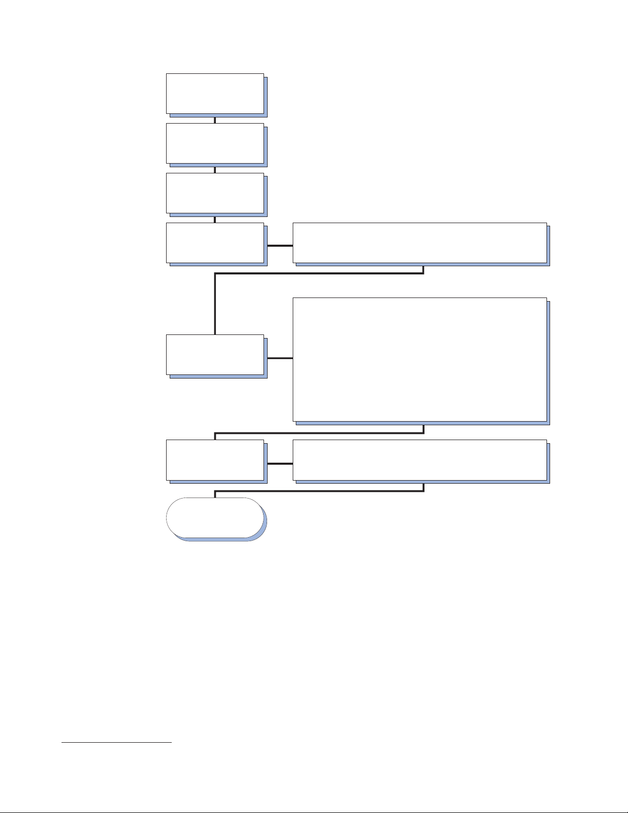
Unpack racks according to
the unpacking instructions
Locate racks according to
IBM NetBAY Rack
the
Planning Guide
Install rack stabilizer
brackets on all racks
Prepare racks for
optional devices
Install one or more
optional devices,
such as:
Complete rack
installation
Rack is setup and
ready for use
• Remove side panels, if applicable
• Remove front and rear doors from all racks, if necessary
• Attach expansion racks to each other or a primary rack to form suites
Note: Install heaviest devices in the bottom of the rack
• Install an uninterruptable power supply (UPS)
• Install a power distribution unit (PDU)
• Install a server
Install a storage expansion unit
•
Install a Fibre Channel RAID controller module
•
Install a Fibre Channel hub
•
Install an SP switch
•
Install a fixed shelf
•
Install a keyboard tray
•
Install a flat panel monitor rack mount kit and flat panel monitor
•
Install a console server selector switch
•
Install a blank filler panel
•
Install a monitor shelf
•
• Reinstall side panels on all racks or outermost racks in a suite
• Reinstall front and rear doors on all racks
Figure 1. Installing the rack cabinet and devices overview
Note: The illustrations in this documentation might be slightly different from your
hardware.
Installing a rack cabinet
The NetBAY25 Rack cabinet is a 25U-high rack cabinet1, while the NetBAY42 Rack
cabinet is a 42U-high rack cabinet. NetBAY25 and primary NetBAY42 Rack cabinets
come with side panels installed.
Note: New rack cabinets come with side and filler panels that are slightly thicker
and heavier than other rack cabinets. You can install the new side or filler
panel FRUs on either type of rack cabinet.
1. One U is equal to 4.45 cm (1.75 in.)
6 Hardware Maintenance Manual: IBM PC Server/Enterprise Racks Types 9306, 9308
Page 17
Expansion NetBAY42 Rack cabinets do not come with side panels, but do include
the required hardware for building a suite of rack cabinets. The rack cabinets
conform to the Electronic Industries Association (EIA) standard EIA-310-D Cabinets,
Racks, Panels, and Associated Equipment (1992).
Note: You need only one primary rack cabinet per suite.
Statement 1:
CAUTION:
To ensure safety, all configurations of the rack cabinet must be certified by a
nationally recognized testing laboratory in order to verify compliance with
country-specific safety regulations. This process ensures that the end
product remains safe for the operator and service personnel under normal
and forseeable misuse conditions.
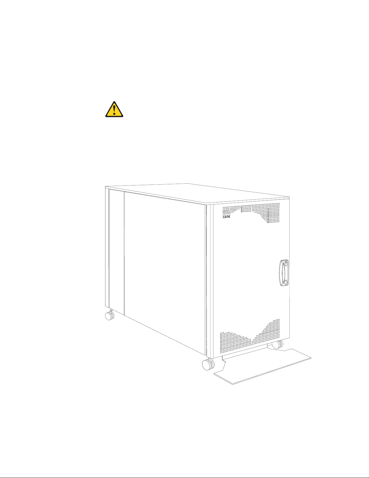
Figure 2. NetBAY25 Rack cabinet
Type 9306 Model 250/420/421 7
Page 18
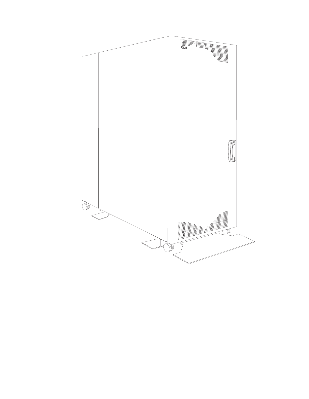
Figure 3. Primary NetBAY42 Rack cabinet with side panels
8 Hardware Maintenance Manual: IBM PC Server/Enterprise Racks Types 9306, 9308
Page 19
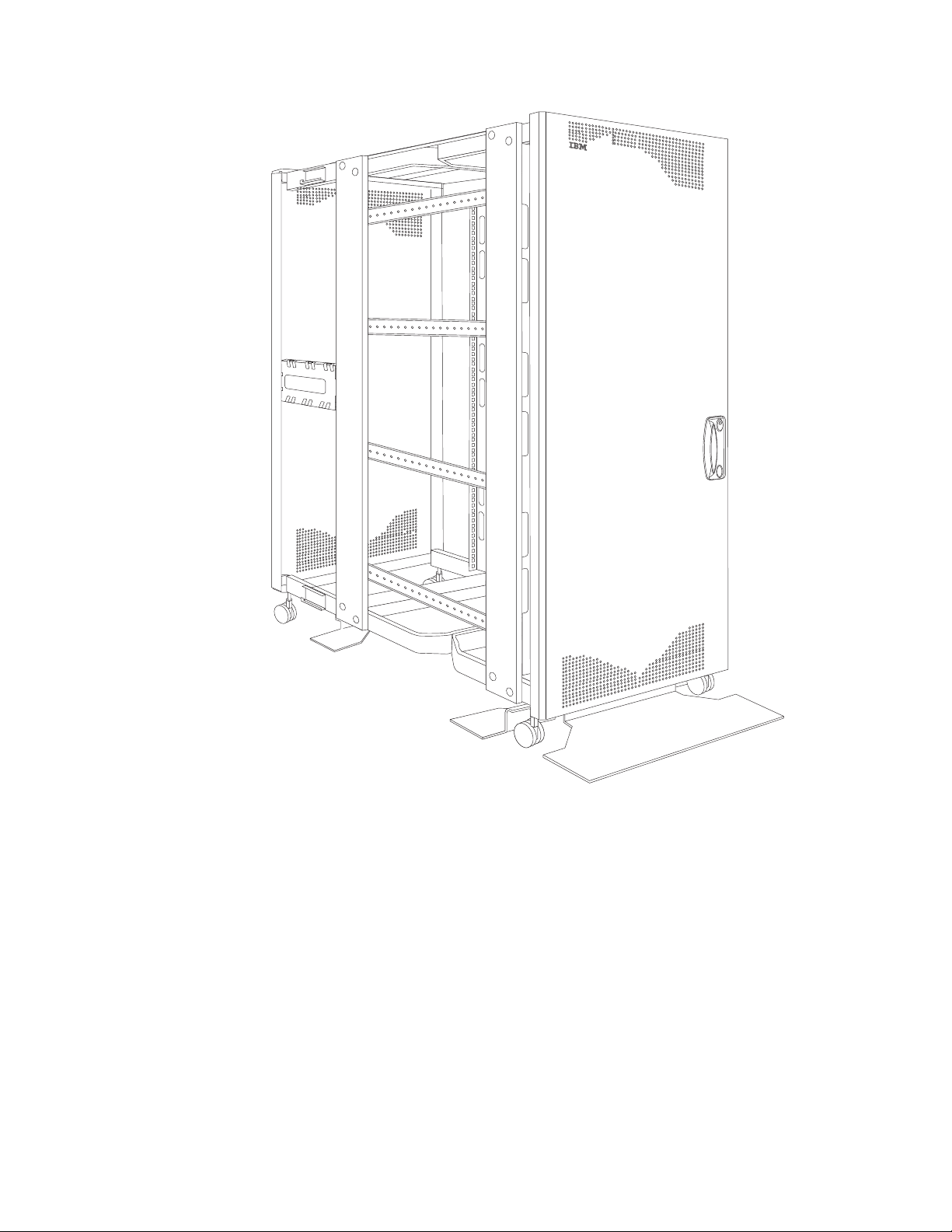
Figure 4. Expansion NetBAY42 Rack cabinet without side panels
Type 9306 Model 250/420/421 9
Page 20
Installing stabilizer brackets
See the unpacking instructions that come with the rack cabinet for information on
how to unpack and locate the rack cabinet; then, lower the rack leveling pads and
install the stabilizer brackets for added stability.
Note: NetBAY25 Rack cabinets have only a front stabilizer bracket. NetBAY42
Rack cabinets have one front and four side stabilizer brackets.
Statement 2:
DANGER
v Always lower the leveling pads on the rack cabinet.
v Always install stabilizer brackets on the rack cabinet.
v Always install servers and optional devices starting from the bottom of
the rack cabinet.
v Always install the heaviest devices in the bottom of the rack cabinet.
Installing the NetBAY25 stabilizer bracket:
Figure 5. Lowering the NetBAY25 leveling pads and installing the stabilizer bracket
1. Use a 12 mm open-end wrench to lower each of the four leveling pads just
enough so that they touch the floor. The rack casters support the weight of the
rack cabinet. The pads prevent the rack from rolling.
2. Attach the stabilizer bracket to the front of the rack cabinet with the screws that
come with the bracket.
3. If necessary, bolt the rack cabinet to the floor through the provided holes in the
stabilizer bracket.
10 Hardware Maintenance Manual: IBM PC Server/Enterprise Racks Types 9306, 9308
Page 21
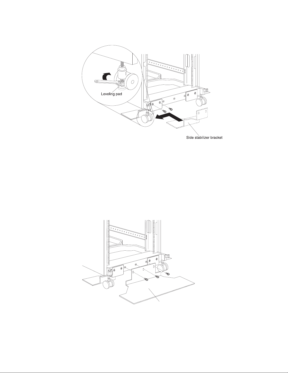
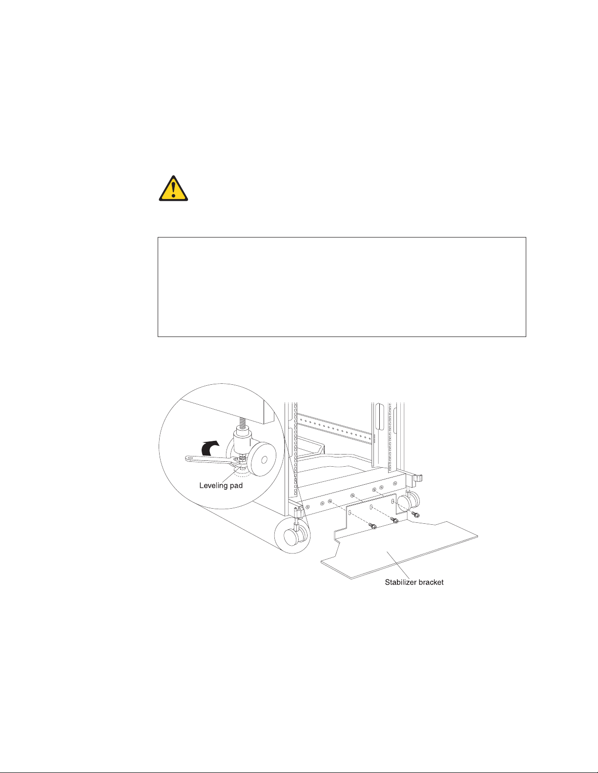
Installing the NetBAY42 stabilizer brackets:
Figure 6. Lowering the NetBAY42 leveling pads and installing the side stabilizer brackets
1. Use a 12 mm open-end wrench to lower each of the four leveling pads just
enough so that they touch the floor. The rack casters support the weight of the
rack cabinet. The pads prevent the rack from rolling.
2. Attach a side stabilizer bracket to the front of the rack cabinet with the screws
that come with the bracket; then, attach the other three side stabilizer brackets.
Note: You must install the side stabilizer brackets so that they extend outward
from the rack cabinet, just behind the casters, as shown in Figure 6.
Front stabilizer bracket
Figure 7. Installing the NetBAY42 front stabilizer bracket
3. Attach the front stabilizer bracket to the front of the rack cabinet with the screws
that come with the bracket.
Type 9306 Model 250/420/421 11
Page 22
4. If necessary, bolt the rack cabinet to the floor through the provided holes in the
stabilizer brackets.
Removing and installing NetBAY25 panels
The NetBAY25 Rack cabinet comes with side panels installed. Remove the side
panels from a rack cabinet before you install or remove optional devices.
Removing and installing side panels: Use the following procedure to remove
the NetBAY25 side panels:
Side panel
Rear
locking bar
Front
locking
bar
Figure 8. Removing the NetBAY25 side panels
1. From the inside rear of the rack cabinet, slide the side panel locking bar into the
unlocked position; then, slide the front side panel locking bar into the unlocked
position.
2. Tilt the bottom of the side panel slightly toward you; then, lift the side panel
away from the tabs on the top of the rack cabinet.
3. Repeat this procedure to remove both side panels.
Reverse this procedure to install the side panels. Slide both locking bars into the
locked position to secure the side panel to the rack cabinet.
12 Hardware Maintenance Manual: IBM PC Server/Enterprise Racks Types 9306, 9308
Page 23
Removing rear filler panels: Use the following procedure to remove the rear filler
panels from the rack cabinet:
Rear filler panel
Figure 9. Removing the NetBAY25 rear filler panels
1. Grasp the rear filler panel firmly and slide it slowly toward the front of the rack
cabinet.
2. Lift the filler panel and remove it from the rack cabinet.
3. Repeat this procedure to remove both filler panels.
Installing rear filler panels: Use the following procedure to install the rear filler
panels on the rack cabinet:
1. Align the bottom of the rear filler panel with the tab on the bottom rear of the
rack cabinet.
2. Hold the filler panel fully against the side of the rack cabinet; then, slide the filler
panel toward the rear of the rack cabinet. Ensure that both the top and bottom
tabs are engaged by the filler panel.
3. Repeat this procedure to install both filler panels.
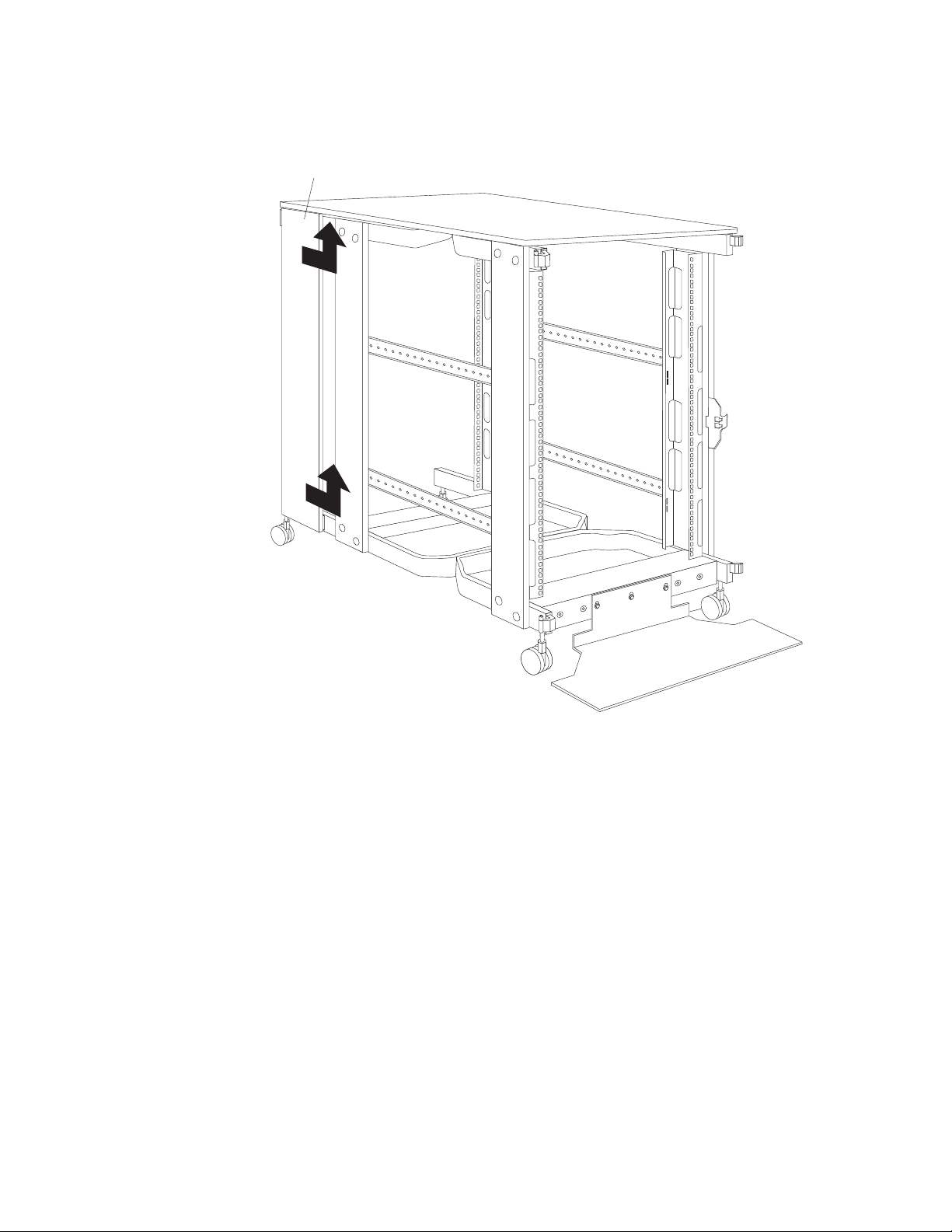
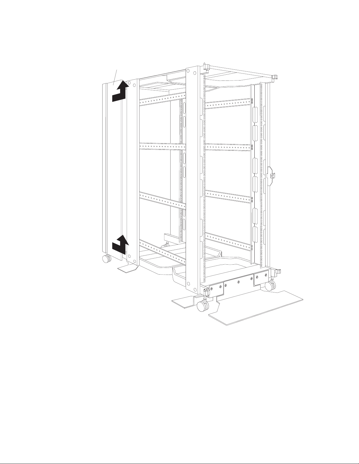
Removing and installing NetBAY42 panels
The primary NetBAY42 Rack cabinet comes with side panels installed. Remove the
side panels from a primary rack cabinet, or the outermost rack cabinets in a suite,
before you install or remove optional devices.
Type 9306 Model 250/420/421 13
Page 24
Note: You do not need to remove the rear filler panels unless you are attaching the
rack cabinets to form a suite of rack cabinets.
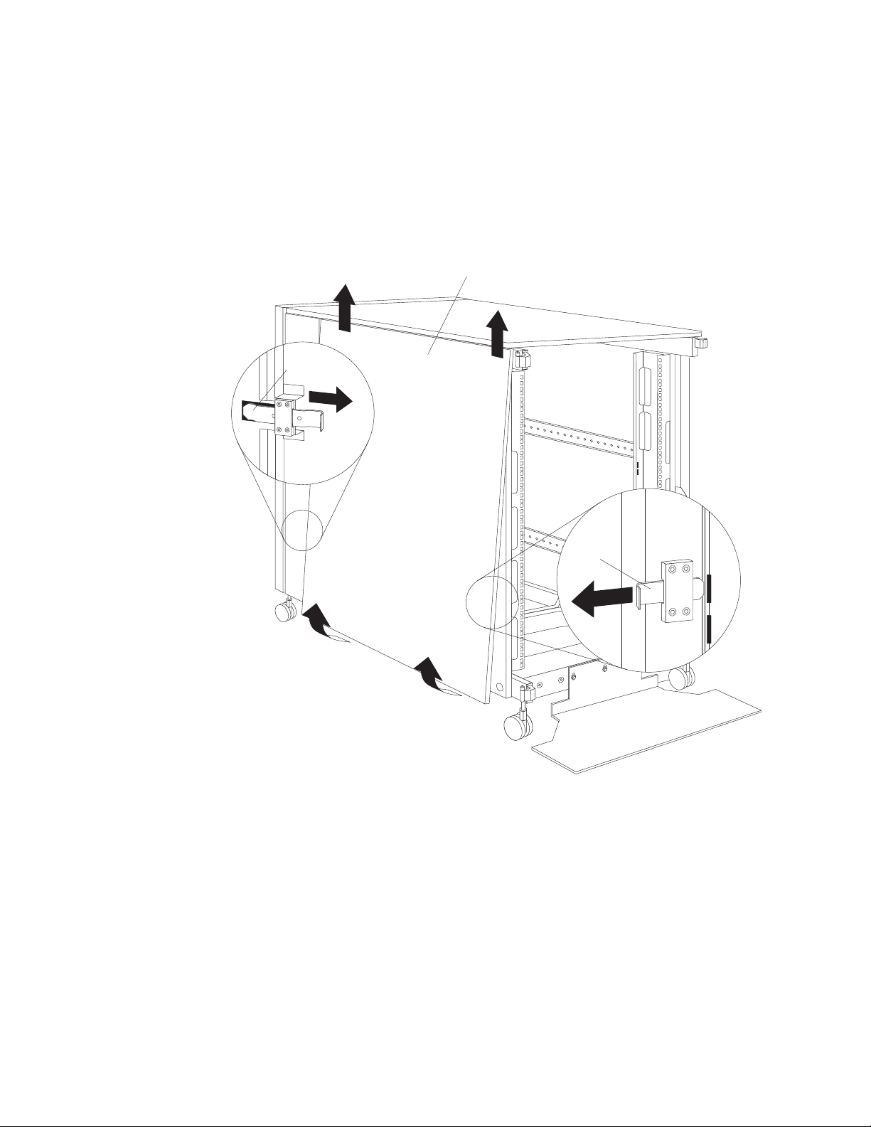
Removing and installing side panels: Use the following procedure to remove
the NetBAY42 side panels:
Side panel
Rear locking bar
Front
locking
bar
Figure 10. Removing the NetBAY42 side panels
1. From the inside rear of the rack cabinet, slide the side panel locking bar into the
unlocked position; then, slide the front side panel locking bar into the unlocked
position.
2. Tilt the bottom of the side panel slightly toward you; then, lift the side panel
away from the tabs on the top of the rack cabinet.
3. Repeat this procedure to remove both side panels.
Reverse this procedure to install the side panels. Slide both locking bars into the
locked position to secure the side panel to the rack cabinet.
14 Hardware Maintenance Manual: IBM PC Server/Enterprise Racks Types 9306, 9308
Page 25
Removing rear filler panels: Use the following procedure to remove the rear filler
panels from the rack cabinet:
Rear filler panel
Figure 11. Removing the NetBAY42 rear filler panels
1. Grasp the rear filler panel firmly and slide it slowly toward the front of the rack
cabinet.
2. Lift the filler panel and remove it from the rack cabinet.
3. Repeat this procedure to remove both filler panels.
Reverse this procedure to install the rear side panels on the rack cabinet.
Installing rear filler panels: Use the following procedure to install the rear filler
panels on the rack cabinet:
1. Align the bottom of the rear filler panel with the tab on the bottom rear of the
rack cabinet.
Type 9306 Model 250/420/421 15
Page 26
2. Hold the filler panel fully against the side of the rack cabinet; then, slide the filler
panel toward the rear of the rack cabinet. Ensure that both the top and bottom
tabs are engaged by the filler panel.
3. Repeat this procedure to install both filler panels.
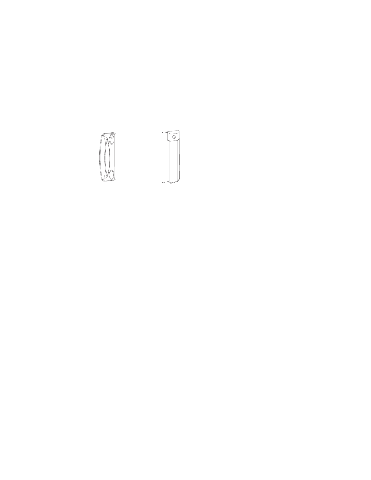
Door latches
Rack cabinets come with doors that have either round or square latches. You can
install either latch FRU on NetBAY25 and NetBAY42 rack cabinets. See the
following illustrations of the two styles of latches.
Note: Doors that come with square latches are slightly thicker and heavier than
doors that come with round latches.
16 Hardware Maintenance Manual: IBM PC Server/Enterprise Racks Types 9306, 9308
Page 27
Removing and installing rack doors
Remove the rack doors when installing and removing options in the rack cabinet. All
rack cabinets come with front and rear doors installed.
Note: You only need to remove a door if part of the rack cabinet is obstructed by
the door as you install the optional device.
Removing and installing a NetBAY25 door: Use the following procedure to
remove a front or rear door from the rack cabinet:
Figure 12. Removing a front door from the NetBAY25 rack cabinet
1. Unlock and open the door.
2. Grasp the door firmly with both hands and lift it upward and away from the
hinges; then, set the door aside.
Reverse this procedure to install the door on the rack cabinet.
Type 9306 Model 250/420/421 17
Page 28
Removing and installing a NetBAY42 door: Use the following procedure to
remove a front or rear door from the rack cabinet:
Figure 13. Removing a front door from the NetBAY42 rack cabinet
1. Unlock and open the door.
2. Grasp the door firmly with both hands and lift it upward and away from the
hinges; then, set the door aside.
Reverse this procedure to install the door on the rack cabinet.
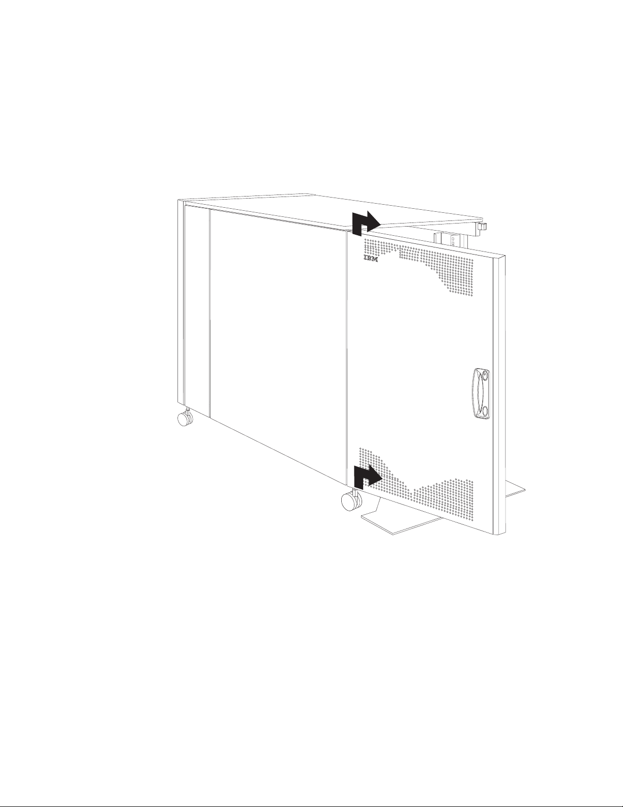
Reversing a front or rear door: Use the following procedure to reverse a front or
rear door on the rack cabinet so that it opens in the opposite direction:
18 Hardware Maintenance Manual: IBM PC Server/Enterprise Racks Types 9306, 9308
Page 29
Note: The illustrations in this procedure are of a NetBAY42 rack cabinet. The same
procedure applies to the NetBAY25 rack cabinet.
1. Remove the door according to “Removing and installing a NetBAY42 door” on
page 18 or “Removing and installing a NetBAY25 door” on page 17.
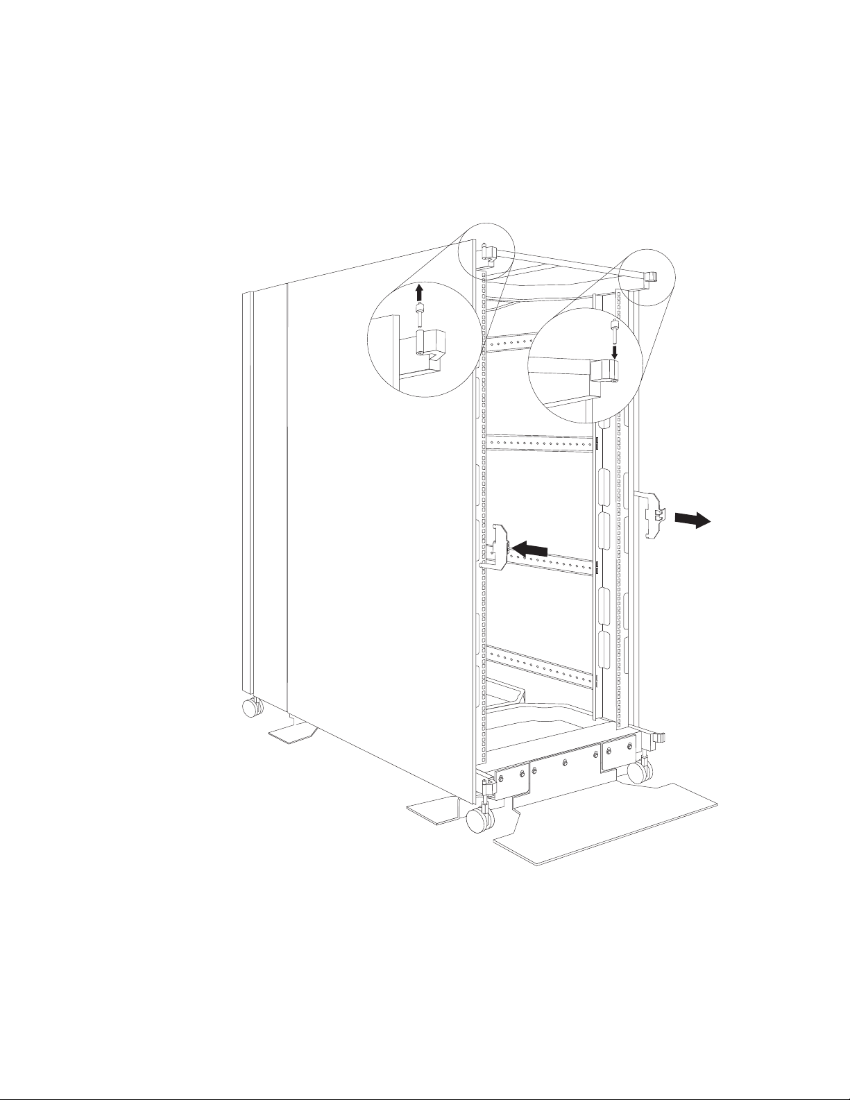
2. Remove the top and bottom hinge pins from the rack cabinet; then, install the
hinge pins on the other side of the rack cabinet.
Figure 14. Moving the hinge pins and front door latch
3. Remove the front door latch and attach it to the other side of the rack cabinet.
Note: The rear door latch is built-in to both rear filler panels, so there is nothing
to move when reversing the rear door on the rack cabinet.
Type 9306 Model 250/420/421 19
Page 30
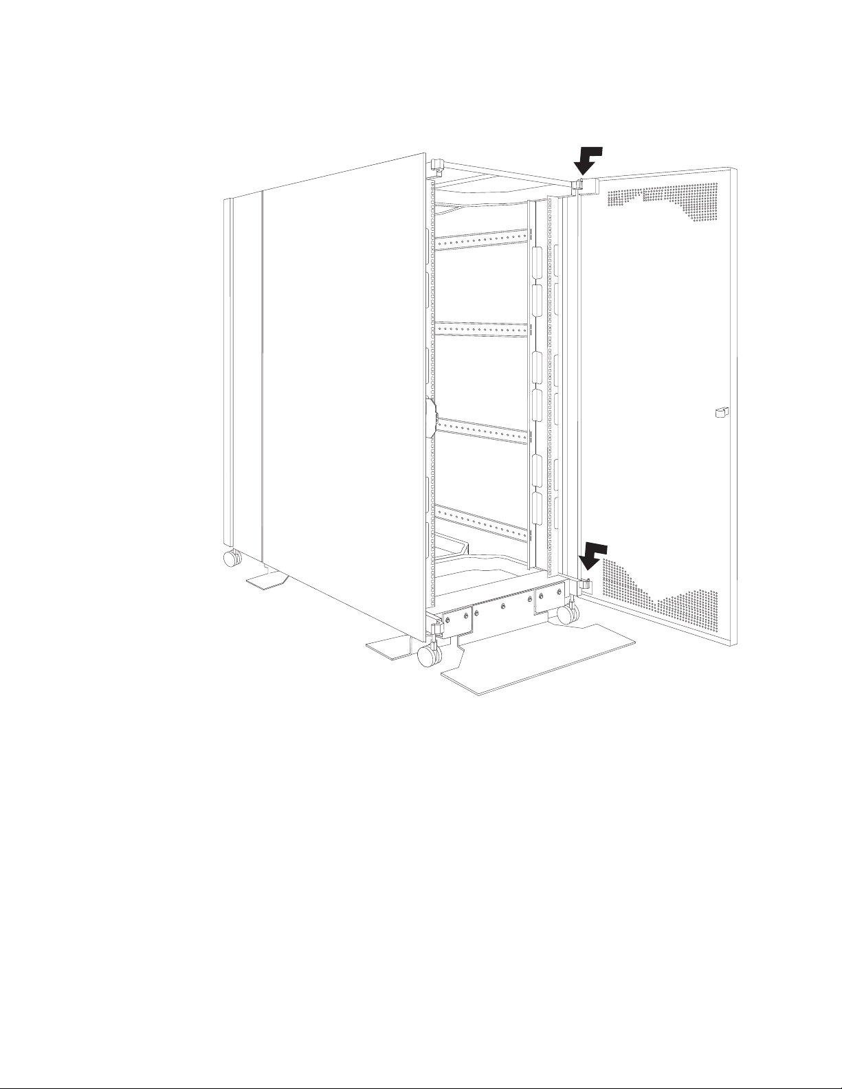
4. Carefully rotate the door 180°; then, install the door on the other side of the rack
cabinet.
Figure 15. Rotating and installing the door
20 Hardware Maintenance Manual: IBM PC Server/Enterprise Racks Types 9306, 9308
Page 31

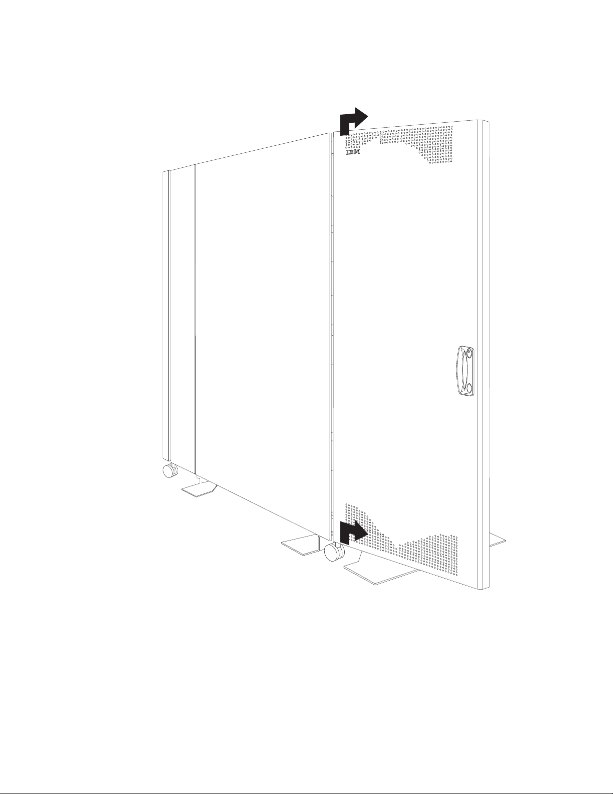
5. Remove the IBM logo from the bottom of the door; then, snap it into place near
the top of the perforated section of the door.
Figure 16. Moving the IBM logo
Type 9306 Model 250/420/421 21
Page 32

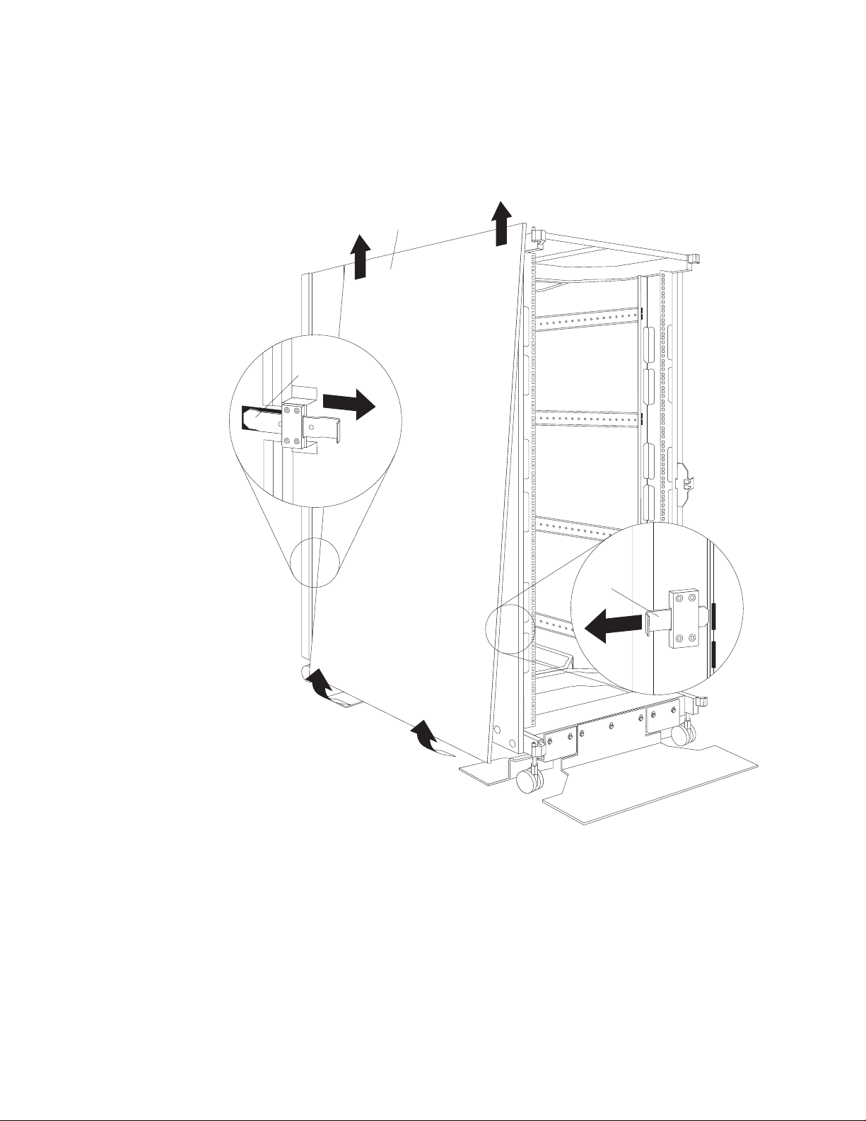
Attaching NetBAY42 Rack cabinets in a suite
Expansion rack cabinets come with all the hardware required for you to attach rack
cabinets together and form a suite. Use the following procedure to attach rack
cabinets together in a suite:
Attachment
bracket
Bolt and nut
Figure 17. Attaching two adjacent NetBAY42 Rack cabinets to each other to form a suite
1. Remove the side panel and rear filler panel (see “Removing and installing
NetBAY42 panels” on page 13) from the side of a primary rack cabinet that is
adjacent to an expansion rack in a suite.
2. Remove the front and rear doors (see “Removing and installing a NetBAY42
door” on page 18) from both rack cabinets.
3. Install the attachment brackets that come with the expansion rack cabinet on
the front and rear of the two adjacent rack cabinets:
a. Insert an attachment bracket into the slots on the front of one of the rack
cabinets as shown in Figure 17; then, insert an attachment bracket into the
slots on the front of the other rack cabinet so that the holes in each bracket
are aligned.
b. Repeat step 3a to install four sets of attachment brackets on the front and
rear of both rack cabinets. Install attachment bracket pairs near the top and
bottom of the rack cabinets.
c. Use the bolts and nuts that come with the expansion rack cabinet to attach
the rack cabinets to each other.
4. Install the panels that you removed in step 1 on the expansion rack cabinet.
22 Hardware Maintenance Manual: IBM PC Server/Enterprise Racks Types 9306, 9308
Page 33

5. If required, move the rear-door-latch-bracket from the expansion rack cabinet to
the right side of a rack cabinet that does not have a rear filler panel installed.
Figure 18. Installing the rear-door-latch-bracket on a rack cabinet
6. Install the front and rear doors on both rack cabinets.
Repeat this procedure if you have other rack cabinets to attach together in a suite.
Managing cables
Always read the instructions that come with your server or optional device for
detailed cable-management information. Use the following general guidelines when
cabling servers or optional devices that you install in a rack cabinet:
Statement 8:
Type 9306 Model 250/420/421 23
Page 34

DANGER
v Plug power cords from devices in the rack cabinet into electrical outlets
that are located near the rack cabinet and are easily accessible.
v Each rack cabinet might have more than one power cord. Be sure to
disconnect all power cords in the rack cabinet before servicing any
device in the rack cabinet.
v Install an emergency-power-off switch if more than one power device
(power distribution unit or uninterruptible power supply) is installed in
the same rack cabinet.
v Connect all devices installed in a rack cabinet to power devices installed
in the same rack cabinet. Do not plug a power cord from a device
installed in one rack cabinet into a power device installed in a different
rack cabinet.
v Do not run cables in front of or behind other devices that will prevent service
access to those devices.
v Do not bend fiber-optic cable beyond its limited specifications.
v Label all cables so that they are clearly distinguishable from each other.
v When installing devices mounted on slide rails, such as servers:
– Run the cables neatly along equipment cable-management arms and secure
the cables to the arms using provided cable straps.
– Leave enough extra cable so that the device can fully extend without straining
the cables.
– Secure the cables so that the device can retract without pinching or cutting
the cables.
v When installing devices mounted on fixed rails:
– Run the cables neatly along the posts or side rails in the rack cabinet out of
the way of other installed devices.
– Secure the cables with the provided cable straps.
v Ensure that the cables cannot be pinched or cut by the rack cabinet rear door or
other devices.
v Run internal cables that connect devices in adjoining rack cabinets through the
large openings provided in the rear of the rack cabinet.
v Run external cables through the bottom of the rack cabinet or through the
removable section in the top of the rack cabinet.
Cable-management brackets
If your rack cabinet comes with cable-management brackets, you must remove the
indicated screw before you can remove a filler panel from the rack cabinet. You can
install the bracket FRU on either type of rack cabinet. If you install these brackets
on a rack cabinet that did not originally come with them, you cannot use a screw to
secure the filler panels unless you also install the new filler panels.
24 Hardware Maintenance Manual: IBM PC Server/Enterprise Racks Types 9306, 9308
Page 35

Note: Make sure that the notch in the cable-management bracket points toward the
front of the rack cabinet when you install the bracket on the rack cabinet.
Cable-management bracket
Notch
Moving a rack cabinet
Fully populated NetBAY25 and NetBAY42 Rack cabinets have been evaluated and
found to meet UL-1950, CSA-950, and IEC-950 stability test standards. Because
these standards apply only to a rack cabinet in an installed location, IBM enforces
additional standards to ensure stability when rolling the rack cabinet on its casters.
See Table 1 for empty and fully populated rack cabinet weights.
Table 1. NetBAY25 and NetBAY42 Rack cabinet weights
NetBAY25 Primary NetBAY42 Expansion NetBAY42
Empty 81 kg (177 lb) 117 kg (258 lb) 92 kg (202 lb)
Populated 466 kg (1027 lb) 763 kg (1678 lb) 737 kg (1622 lb)
When you move a rack cabinet, adhere to the following standards:
Statement 8:
Type 9306 Model 250/420/421 25
Page 36

DANGER
v Plug power cords from devices in the rack cabinet into electrical outlets
that are located near the rack cabinet and are easily accessible.
v Each rack cabinet might have more than one power cord. Be sure to
disconnect all power cords in the rack cabinet before servicing any
device in the rack cabinet.
v Install an emergency-power-off switch if more than one power device
(power distribution unit or uninterruptible power supply) is installed in
the same rack cabinet.
v Connect all devices installed in a rack cabinet to power devices installed
in the same rack cabinet. Do not plug a power cord from a device
installed in one rack cabinet into a power device installed in a different
rack cabinet.
26 Hardware Maintenance Manual: IBM PC Server/Enterprise Racks Types 9306, 9308
Page 37

Statement 11:
CAUTION:
Removing components from the upper positions in the rack cabinet improves
rack stability during relocation. Follow these general guidelines whenever you
relocate a populated rack cabinet within a room or building:
v Reduce the weight of the rack cabinet by removing equipment starting at
the top of the rack cabinet. When possible, restore the rack cabinet to the
configuration of the rack cabinet as you received it. If this configuration is
not known, you must do the following:
– Remove all devices in the 22U position and above.
– Ensure that the heaviest devices are installed in the bottom of the rack
cabinet.
– Ensure that there are no empty U-levels between devices installed in the
rack cabinet below the 22U level.
v If the rack cabinet you are relocating is part of a suite of rack cabinets,
detach the rack cabinet from the suite.
v Inspect the route that you plan to take to eliminate potential hazards.
v Verify that the route that you choose can support the weight of the loaded
rack cabinet. Refer to the documentation that comes with your rack cabinet
for the weight of a loaded rack cabinet.
v Verify that all door openings are at least 760 x 2083 mm (30 x 82 in.)
v Ensure that all devices, shelves, drawers, doors, and cables are secure.
v Ensure that the four leveling pads are raised to their highest position.
v Ensure that there is no stabilizer bracket installed on the rack cabinet.
v Do not use a ramp inclined at more than ten degrees.
v Once the rack cabinet is in the new location, do the following:
– Lower the four leveling pads.
– Install stabilizer brackets on the rack cabinet.
– If you removed any devices from the rack cabinet, repopulate the rack
cabinet from the lowest position to the highest position.
If a long distance relocation is required, restore the rack cabinet to the
configuration of the rack cabinet as you received it. Pack the rack cabinet in
the original packaging material, or equivalent. Also, lower the leveling pads to
raise the casters off of the pallet and strap the rack cabinet to the pallet.
Type 9306 Model 250/420/421 27
Page 38

Part Listing (Type 9306)
14
4
4
12
16
16
7
8
10
9
11
15
5
6
13
3
1
2
Index Rack Enclosure (Type 9306) FRU
1 42U Door (Models 420, 421) 06P6074
1 25U Door (Model 250) 32P1008
2 Left Hand and Right Hand Side Stabilizer (Models 420, 421) 06P6077
3 Front Stabilizer (Models 250, 420, 421) 06P6076
4 Braces (Models 250, 420, 421) 06P6063
5 42U - 900 Front Top Cover (Models 420, 421) 06P6064
5 42U -100 Rear Top Cover (Models 420, 421) 06P6065
5 42U - Top Side Gland Plate (Models 420, 421) 06P6066
5 25U - Top Cover (Model 250) 32P1003
6 Front Door Striker Plate (Models 250, 420, 421) 06P6067
7 Left Hand 25U x 200 Single Side Panel (Model 250) 32P1006
7 Right Hand 42U x 200 Single Side Panel (Models 420, 421) 32P1016
8 Left Hand 42U x 200 Single Side Panel (Models 420, 421) 06P6072
8 Right Hand 25U x 200 Single Side Panel (Model 250) 32P1007
9 Left Hand 42U x 800 Single Side Panel (Models 420, 421) 06P6070
9 Left Hand 25U x 800 Single Side Panel (Model 250) 32P1004
10 Right Hand 42U x 800 Single Side Panel (Model 420, 421) 32P1000
10 Right Hand 25U x 800 Single Side Panel (Model 250) 32P1005
11 42U Symm Front Panel MTG. MBR (Models 420, 421) 06P6059
11 25U Symm Front Panel MTG. MBR (Model 250) 32P1009
12 42U Rear Symm Front Panel MTG. MBR (Models 420, 421) 06P6061
12 25U Rear Symm Front Panel MTG. MBR (Model 250) 32P1011
13 42U Base Cross Box (Models 420, 421) 32P1015
13 25U Base Cross Box (Model 250) 32P1013
14 42U x 600 x 1000 Rack Framework Only (Models 420, 421) 06P6054
28 Hardware Maintenance Manual: IBM PC Server/Enterprise Racks Types 9306, 9308
Page 39

Index Rack Enclosure (Type 9306) FRU
14 25U x 600 x 1000 Rack Framework Only (Model 250) 32P1010
15 Swivel Caster (Models 250, 420, 421) 06P6055
16 Swivel Caster (Models 250, 420, 421) 06P6055
Cable management bracket( Model 250) 32P1784
Cable management bracket( Models 420, 421) 32P1785
Caster set (Models 250, 420, 421) 32P1696
Door with round latch (Model 250) 32P1008
Door with round latch (Models 420, 421) 06P6074
Door with square latch (Model 250) 32P1783
Door with square latch (Models 420, 421) 32P1782
Filler panel, left (Model 250) 32P1778
Filler panel, left (Models 420, 421) 32P1774
Filler panel, right (Model 250) 32P1779
Filler panel, right (Models 420, 421) 32P1781
Latch, round (Models 250, 420, 421) 06P6075
Latch, square (Models 250, 420, 421) 32P1017
Rear Door Striker (Models 250, 420, 421) 06P6068
Side panel, left (Model 250) 32P1776
Side panel, left (Models 420, 421) 32P1780
Side panel, right (Model 250) 32P1777
Side panel, right (Models 420, 421) 32P1775
42U Two Color Unit Identification Strip (Models 420, 421) 06P6069
25U Two Color Unit Identification Strip (Model 250) 32P1012
Side Panel Sliding Latch (Models 250, 420, 421) 06P6071
Hinge Pin (Models 250, 420, 421) 06P6073
Door Lock Assembly (Models 250, 420, 421) 06P6075
Fixings and Tools (Models 250, 420, 421) 06P6079
42U Baying Bracket (Models 420, 421) 06P6080
25U Top Cover Cable Access Hole Cover (Model 250) 28L0553
25U Top Cover MTG. Bracket Kit (Model 250) 32P1014
Door Keys (Models 250, 420, 421) 32P1002
25U Single Color Unit Identification Strip (Model 250) 32P1034
42U Single Color Unit Identification Strip (Models 420, 421) 32P1035
Type 9306 Model 250/420/421 29
Page 40

30 Hardware Maintenance Manual: IBM PC Server/Enterprise Racks Types 9306, 9308
Page 41

Type 9306 Models 200/900/910
Type 9306 Models 900/910
Features
The IBM NetBAY22, Type 9306, Model 200 Rack enclosure is a 22-U (1-U = 1.75
inch) industry-standard, 19-inch rack that houses and controls multiple IBM PC
Servers/IBM Servers and related equipment.
Locations
The following sections contain information on specific equipment locations.
Note: For instructions on how to power-off the rack, see “Powering off the rack” on
page 3.
Side panel
Locked Unlocked
© Copyright IBM Corp. 2001 31
Page 42

Parts Listing (Type 9306 Model 200)
10
9
8
7
1
2
3
4
5
6
32 Hardware Maintenance Manual: IBM PC Server/Enterprise Racks Types 9306, 9308
Page 43

Index Rack Enclosure (Type 9306 Model 200) FRU
1 Top Cover including cover standoffs and screws 28L0548
2 Rear EIA Rail (1) includes mounting hardware 28L0547
3 Rack Frame 28L0550
Caster (1) 12J4466
Leveler (1) 76H4960
4 Rear Door Assembly including latch and lock 28L0545
5 Side Panel Assembly with Latches and Lock 28L0549
Side Panel Latches 12J4468
Side Panel Lock with Keys 76H4965
6 Caster Extension Plinth (1) 12J4482
7 Stabilizer 12J4485
8 Front Door Assembly including latch and lock 28L0544
9 Front EIA Rail (1) includes mounting hardware 28L0546
10 Side Brace (1) 12J4477
Front/Rear Door Hinge with Pin (1) 76H4966
Front/Rear Door Latch with Lock and Keys (1) 76H4967
Front/Rear Door Striker Plate (1) includes mounting hardware 12J4465
Front/Rear Door Hinge Pin (1) 12J4469
Grommet, Cable Exit 28L0553
Label, EIA Unit Numbers 28L0551
Miscellaneous Parts Kit - Includes: M6X25 Pan Head Screw (1), M6 Caged Nut (6), M6X16
76H4950
Combination Head Screw (6), 10-32 Flat Washer (6), M6X12 Button Socket Head Cap
Screw (5), 12mm Open End Wrench (1), M6 Tinnerman Clip (2), M6 Threaded Hex Spacer
(1), M6 Dome Nut (2), M6 Flange Nut (5), Soft Tie Wraps (10)
Rack Enclosure (Type 9306 Model 200) Options FRU
Monitor Housing 76H4947
Filler Panels: 1U, 3U, and 5U - with hardware 12J4473
Keyboard Tray 76H4958
Keyboard Tray II 28L0562
Keyboard Tray II filler block 28L0567
Keyboard Slides (set) with Hardware 76H4961
Fixed Shelf with Hardware 76H4963
C13 - C14 Power Cable 07H0075
C19 - C14 Power Cable 76H4964
C13 - NEMA 5-15P Power Cable 76H4962
C19 - NEMA 5-15P Power Cable 12J4479
Video, Mouse, Keyboard Cable (7 feet) 06P6006
Video, Mouse, Keyboard Cable (12 feet) 06P6007
Video, Mouse, Keyboard Power Cable (25 feet) 12J4484
Mouse Extension Cable 07H0069
Keyboard Extension Cable 07H0067
Concentrator (4 port) with Hardware 28L0543
Concentrator (8 port) with Hardware 76H4948
1x4 switch 06P6003
2x8 switch 06P6004
NetBAY Rack Power Distribution Unit 09N9668
NetBAY Front-end Power Distribution Unit 09N9670
3-phase NEMA L21-30P line cord (200-250 Vac) for NetBAY Front-end PDU 24P6844
3-phase IEC 309-3P+N+Gnd line cord (380-415 Vac) for NetBAY Front-end PDU 24P6845
1-phase NEMA L5-30P line cord (100-127 Vac) for NetBAY Front-end PDU 24P6846
1-phase NEMA L6-30P line cord (200-240 Vac) for NetBAY Front-end PDU 24P6847
1-phase IEC 309-2P+Gnd line cord (200-240 Vac) for NetBAY Front-end PDU 24P6848
NetBAY Server Dual-cord Power Distribution Unit 09N9669
Type 9306 Models 200/900/910 33
Page 44

Rack Enclosure (Type 9306 Model 200) Options FRU
Hardware Kit for NetBAY Power Distribution Units 09N9671
Flat Panel Monitor Rack Mount Kit (T54A, models AG1, AW1; T55) 37L6888
Flat Panel Adapter Hinge - R.H. & L.H. (T54A, T55) 09N9678
Flat Panel Adapter Misc. Hardware Kit – Includes: Hinge Cover (1), Power Supply Cover
(1), Mounting Stud (1), Bumper (2), Cable Access Cover (1), M4 X 12 Screw (4), M4 X 8
Screw (2), 14 inch Soft Tie Wrap (1), T54A power supply spacer (1)
Flat Panel Adapter Display Housing – Includes: Power Supply Cover (1), Base Housing (1),
Cable Access Cover (1), Bottom Stand
Type 9306 Model 900/910
Features
The IBM Server 9306-900/910 Rack enclosure is an industry-standard, 19-inch rack
that houses and controls multiple IBM PC Servers/IBM Servers and related
equipment.
v Model 900 has optional side panels, solid front door, and perforated rear door.
v Model 910 has side panels and perforated front and rear doors.
Locations
The following sections contain information on specific equipment locations.
00N8693
00N8694
Note: For instructions on how to power-off the rack, see “Powering off the rack” on
page 3.
Side Panel
Locked Unlocked
34 Hardware Maintenance Manual: IBM PC Server/Enterprise Racks Types 9306, 9308
Page 45

Perforated Doors (model 910)
The Type 9306 Model 910 Rack comes with front and rear perforated doors that
provide enhanced cooling and airflow for components you install in your rack
cabinet. The 9306 Model 910 Rack also comes with side panels already installed.
®
Refer to installation instructions in this document if you have a 9306 Model 900
Rack and are installing a new perforated front door.
Note: The illustrations in this documentation might be slightly different from your
hardware.
Installing the new door on a model 900 rack cabinet
Use the following steps to remove your existing front door and install the new
perforated door:
1. Refer to the rack documentation for information on removing side panels; then,
remove the left side panel on the rack and set it aside.
Type 9306 Models 200/900/910 35
Page 46

2. If the front door is locked, unlock it; then, open the front door.
Locked Unlocked
3. While supporting the door, remove all four hinge pins that hold the front door in
place; then, store the door in a safe place for possible future use.
Note: Save three of the hinge pins for later installation.
4. Remove the screw and nut that holds the hinge bracket 1 in place; then,
move the hinge bracket 2 three mounting spaces downward and reinstall it at
the new center location.
36 Hardware Maintenance Manual: IBM PC Server/Enterprise Racks Types 9306, 9308
Page 47

®
Note: Insert the screw through the bracket and into the lower of the two holes
in the new center location.
5. Remove the other hinge bracket 3 and store it with the old door that you
removed earlier.
6. While supporting the new door, use three of the hinge pins that you removed
from the old door to attach the new door to your rack cabinet. Store the fourth
hinge pin with the old door and hinge bracket.
7. Reinstall the left side panel that you removed earlier.
Type 9306 Models 200/900/910 37
Page 48

Parts listing (Type 9306 Model 900/910)
9
8
11 2
10
7
1
3
4
5
6
38 Hardware Maintenance Manual: IBM PC Server/Enterprise Racks Types 9306, 9308
Page 49

Index Rack Enclosure (Type 9306 Model 900/910) FRU
1 Top Cover including cover standoffs and screws 12J4481
2 Rear EIA Rail (1) includes mounting hardware 76H4956
3 Rack Frame 76H4959
Caster (1) 12J4466
Leveler (1) 76H4960
4 Rear Door Assembly including latch and lock 12J4478
5 Side Panel Assembly (option for model 900, standard for model 910) including latches
76H4949
and lock
6 Stabilizer Bar (1) 12J4467
7 Caster Extension Plinth (1) 12J4482
8 Front Stabilizer (1) 12J4485
9 Front Door Assembly (model 900 only) including latch and lock 76H4942
9 Front Door Assembly (model 910 only) including latch and lock 12J4478
10 Front EIA Rail (1) includes mounting hardware 76H4951
11 Side Brace (1) 12J4477
Front/Rear Door Hinge with Pin (1) 76H4966
Front/Rear Door Latch with Lock and Keys 76H4967
Front/Rear Door Striker Plate (1) includes mounting hardware 12J4465
Front/Rear Door Hinge Pin (1) 12J4469
Label, EIA Unit Numbers 12J4471
Miscellaneous Parts Kit - Includes: 76H4950
M6X25 Pan Head Screw (1)
M6 Caged Nut (6)
M6X16 Combination Head Screw (6)
10-32 Flat Washer (6)
M6X12 Button Socket Head Cap Screw (5)
12mm Open End Wrench (1)
M6 Tinnerman Clip (2)
M6 Threaded Hex Spacer (1)
M6 Dome Nut (2)
M6 Flange Nut (5)
Soft Tie Wraps (10)
Rack Enclosure (Type 9306 Model 900/910) Options FRU
Monitor Housing 76H4947
Side Panel Lock with Keys 76H4965
Side Panel Latch 12J4468
Filler Panels: 1U, 3U, and 5U - with Hardware 12J4473
Keyboard Tray 76H4958
Keyboard Tray II 28L0562
Keyboard Tray II filler block 28L0567
Keyboard Slides (set) with Hardware 76H4961
Fixed Shelf with Hardware 76H4963
Rack to Rack Mounting Kit - Includes: Horizontal Trim (1); Vertical Trim (2); M6x16
12J4476
Screws (12); M6 Cage Nuts (4); M6 Whiz nuts (10); Brackets, Rack Mounting (4)
C13 - C14 Power Cable 07H0075
C19 - C14 Power Cable 76H4964
C13 - NEMA 5-15P Power Cable 76H4962
C19 - NEMA 5-15P Power CablE 12J4479
Video, Mouse, Keyboard Cable (7 feet) 06P6006
Video, Mouse, Keyboard Cable (12 feet) 06P6007
Video, Mouse, Keyboard Power Cable (25 feet) 12J4484
Mouse Extension Cable 07H0069
Keyboard Extension Cable 07H0067
Type 9306 Models 200/900/910 39
Page 50

Rack Enclosure (Type 9306 Model 900/910) Options FRU
Concentrator with Hardware (8 port) 76H4948
Concentrator with Hardware (4 port) 28L0543
1x4 switch 06P6003
2x8 switch 06P6004
NetBAY Rack Power Distribution Unit 09N9668
NetBAY Front-end Power Distribution Unit 09N9670
3-phase NEMA L21-30P line cord (200-250 Vac) for NetBAY Front-end PDU 24P6844
3-phase IEC 309-3P+N+Gnd line cord (380-415 Vac) for NetBAY Front-end PDU 24P6845
1-phase NEMA L5-30P line cord (100-127 Vac) for NetBAY Front-end PDU 24P6846
1-phase NEMA L6-30P line cord (200-240 Vac) for NetBAY Front-end PDU 24P6847
1-phase IEC 309-2P+Gnd line cord (200-240 Vac) for NetBAY Front-end PDU 24P6848
NetBAY Server Dual-cord Power Distribution Unit 09N9669
Hardware Kit for NetBAY Power Distribution Units 09N9671
Flat Panel Monitor Rack Mount Kit (T54A, models AG1, AW1; T55) 37L6888
Flat Panel Adapter Hinge - R.H. & L.H. (T54A, T55) 09N9678
Flat Panel Adapter Misc. Hardware Kit – Includes: Hinge Cover (1); Power Supply
Cover (1); Mounting Stud (1); Bumper (2); Cable Access Cover (1); M4 X 12 Screw
(4); M4 X 8 Screw (2); 14 inch Soft Tie Wrap (1); T54A power supply spacer (1)
Flat Panel Adapter Display Housing – Includes: Power Supply Cover (1); Base
Housing (1); Cable Access Cover (1); Bottom Stand
00N8693
00N8694
40 Hardware Maintenance Manual: IBM PC Server/Enterprise Racks Types 9306, 9308
Page 51

Type 9306 Models 4QS, 4QX, 9QS, 9QX, 9TS, 9TX
Features
The 9306 IBM PC Server Rack Enclosure, models 4QS, 9QS, 9TS come in three
primary models.
v 19-inch Quad Primary Server Rack, Model 9QS
v 19-inch Tri Primary Server Rack, Model 9TS
v 24-inch Quad Primary Server Rack, Model 4QS
A Quad Primary Server Rack can house up to four IBM PC Servers. The Tri
Primary Server Rack can house up to three IBM PC Servers.
Both Quad and Tri Primary Server Racks provide a built in server selector which
connects to one set of console devices (monitor, keyboard, and mouse.) The server
selector works independently from the server’s operating systems, enabling the
connected servers to run different operating systems.
These IBM 9306 PC Server Rack Enclosure models are shipped preassembled and
pre-cabled.
IBM PC Server expansion rack models
Three optional IBM PC Server Rack Expansion models are available to expand the
capacity of the IBM PC Server Rack Primary Enclosure. The optional IBM PC
Server Rack Expansion models are:
v 19-inch Quad Expansion Rack, Model 9QX
v 19-inch Tri Expansion Rack, Model 9TX
v 24-inch Quad Expansion Rack, Model 4QX
The IBM PC Server Rack Expansion models allow the installation of up to four
more servers using the Primary IBM PC Server Rack monitor, keyboard, and
mouse.
Locations
The following sections contain information on specific equipment locations.
Note: For instructions on how to power-off the rack, see “Powering off the rack” on
page 3.
Server selector console
To remove the Server Selector Console:
1. Power-off the rack.
2. Use an 1/8-inch allen wrench to remove screws.
3. Disconnect the server selector cable from the back of the server selector
console.
4. Remove the server selector console from the cabinet.
© Copyright IBM Corp. 2001 41
Page 52

Monitor
Bezel
Server
Selector
Console
Server selector unit
The server selector unit is located in the upper rear of the rack cabinet. The server
selector unit can only be accessed or removed from the rear of the IBM Rack
cabinet.
CAUTION:
The server selector unit is heavy. You will need two people to safely remove
the server selector unit. See “Safety notices (multilingual translations)” on
page 198.
To remove the server selector unit:
1. Power-off the rack.
2. Unplug the keyboard, mouse, video cables, and the power cord.
3. Remove the server selector console.
4. With one person bracing the server selector unit from below, have the second
person use a 5/16-inch wrench to remove the four nuts that secure the server
selector unit to the rack cabinet.
5. Remove the server selector unit from the cabinet.
Server
Selector
Keypad
Server
Selector
Electronics
Server
Selector
Cable
Note: When replacing the server selector unit, be sure that the Server Selector
cable is fed through the indentation along the left side of the server selector
unit.
Server
Selector
Cable
Server
Selector
Unit
42 Hardware Maintenance Manual: IBM PC Server/Enterprise Racks Types 9306, 9308
Page 53

Connections
Server Rack
Monitor
Connection
AC Power
Input
Server
Monitor
Connections
Server Selector
Unit On-Off
Switch
V
M
G
O
A
N
1
O
M
K
K1M1K2M2K3M3K4M4K5M5K6M6K7M7K8M
O
B
U
O
Server Rack
Mouse
Connection
Server Rack
Keyboard
Connection
Power distribution unit
Note: For information and installation instructions for the IBM NetBAY Rack Power
Distribution Units, see “Installing Optional Devices” on page 101″.
Note: To remove the power distribution unit, you might need to remove the right
side cabinet panel, the server installed in sliding tray 2 (in the primary IBM
PC Server Rack), or sliding tray 5 (in the IBM PC Server Expansion Rack).
To remove the power distribution unit:
1. Power-off the rack.
2. Disconnect all power plugs from the power distribution unit.
3. Using a Phillips screwdriver, remove the four screws from the front of the power
distribution unit.
V
G
A
2
G
G
A
A
4
3
G
G
A
A
6
5
Server Keyboard
and Mouse
Connections
V
V
V
V
V
V
G
G
A
A
8
7
8
Note: These screws are held in place by nuts and washers. Hold the nut while
you are unscrewing the screw to prevent the nut and washer from falling
into the bottom of the cabinet.
4. Remove the power distribution unit from the cabinet.
Type 9306 Models 4QS, 4QX, 9QS, 9QX, 9TS, 9TX 43
Page 54

Cooling fan
AC Power
Input
AC Fuse
Circuit
Breaker
115V AC
Power-On
Indicator
Voltage
Selection
Switch
230V AC
Power-On
Indicator
AC Power
Output
To remove the cooling fan:
1. Power-off the rack.
2. Open the rear door of the rack cabinet.
3. Disconnect the power plug from the rear of the cooling fan.
4. Use a 5/16-inch wrench to remove the eight nuts that secure the cooling fan to
the top of the rack cabinet.
5. Remove the cooling fan from the cabinet.
Note: When installing the fan, make sure that the green and yellow ground wire is
attached to one of the top fan mounting screws and that the strain-relieving
clamp is attached to another. The power cable should be secured by the
44 Hardware Maintenance Manual: IBM PC Server/Enterprise Racks Types 9306, 9308
Page 55

Sliding trays
strain-relieving clamp.
Ground
Wire
Power
Plug
Models 4QS and 4QX come with either single latch slide rails or dual latch slide
rails. Single latch slide rails have a front latch release on the right rail only. Dual
latch slide rails have a front latch release on both rails. The slide rail FRU number
for the 24-inch rack replaces the single latch slide rail with the dual latch slide rail.
Note: If a server is installed on a tray being removed, first remove the server.
Single latch rail tray
To remove a sliding tray with single latch rails:
1. Power-off the rack.
2. Open the rear door of the rack cabinet and remove the pin 1 that secures the
sliding tray to the cable management arm
3. Loosen the thumbscrews 2 on the sliding tray and fully extend the sliding tray.
4. Use a 3/32-inch allen wrench to remove the five screws 3 from the left side of
the sliding tray.
5. Lift the rear locking tab 4 and push the sliding tray approximately two inches
into the cabinet.
6. Release the forward locking tab 5. Then, while holding the sliding tray in
place, use your other hand to grasp the outside sliding rail 6 and push it into
the rack cabinet until it disconnects from the sliding tray.
Type 9306 Models 4QS, 4QX, 9QS, 9QX, 9TS, 9TX 45
Page 56

Dual latch rail tray
To remove a sliding tray with dual latch rails:
1. Power-off the rack.
2. Open the rear door of the rack cabinet and remove the pin 1 that secures the
sliding tray to the cable management arm.
3. Loosen the thumbscrews 2 on the sliding tray and fully extend the sliding tray.
4. Push in on the spring of the right rear locking tab 3 and push the sliding tray
approximately two inches into the cabinet.
5. Release both left and right forward locking tabs 4. Then, while holding the
sliding tray in place, push both left and right outside sliding rails 5 into the
rack cabinet until it disconnects from the sliding tray.
Note: Left side view for 4 and5 are not shown.
Sliding rails
This procedure is for single latch sliding rails and dual latch sliding rails.
For single latch sliding rails, the right rail is the one that has the front latch. The left
rail does not have a front latch.
For dual latch sliding rails, the right rail is the one that has the rear latch. The left
rail does not have a rear latch.
To remove the sliding rails:
1. Power-off the rack.
2. Remove the sliding tray that is attached to the sliding rails that you want to
remove. See “Sliding trays” on page 45.
3. Use a 3/32-inch allen wrench to remove the four screws that secure each of the
sliding rails to the rack cabinet.
46 Hardware Maintenance Manual: IBM PC Server/Enterprise Racks Types 9306, 9308
Page 57

Keyboard tray
Note: You will need to adjust the position of the sliding rail in order to line up the
access holes over the locations of the screws.
To remove the keyboard tray:
1. Power-off the rack.
2. Disconnect the keyboard and mouse cables from the keyboard and mouse
extension cables.
3. Remove the keyboard and mouse from the keyboard tray.
4. Pull the keyboard tray straight out of the rack cabinet.
Type 9306 Models 4QS, 4QX, 9QS, 9QX, 9TS, 9TX 47
Page 58

Parts listing (Type 9306 – 19-inch) Models 9QS, 9TS and 9QX, 9TX
This parts listing is for Models 9QS, 9TS and 9QX, 9TX
4
8
6
5
3
7
9
10
11
27
1
28
26
2
30
29
24
23
19
20
22
25
21
18
17
13
12
14
15
16
48 Hardware Maintenance Manual: IBM PC Server/Enterprise Racks Types 9306, 9308
Page 59

Index 19-Inch Rack Enclosure (Type 9306) FRU
1 Adapter Plate Options:
PS/2 Server 85/95 76H3733
Model 300 76H3734
Model 500, 700 76H3734
2 Monitor Stand 07H0061
3 Server Selector Cable 07H0036
4 Blank Bezel (9QX, 9TX Expansion units only) 76H0379
5 Monitor Bezel with button label 76H0378
6 Server Selector Keypad 07H0097
7 Monitor Housing (19-inch) 76H0377
8 Server Selector Unit Electronics
07H0034
See “Safety inspection guide” on page 229.
9 Internal Cables
06P6007
See Cable Kit Shelf Server
10 Cable Management Arm 76H0386
11 Cable Management Arm Single Server Tray 76H0387
12 Pin, Cable Management Arm 07H0089
13 Fan 220 V ac with Power Cord 07H0063
14 Latch, Rear Door 76H0376
15 Rear Door (19-Inch) 76H0373
15 Hinge Set for Rear Door 76H0389
16 External Power Cord:
Australia 14F1559
Europe 14F1554
Israel 14F1561
Italy 14F1560
New Zealand 14F1558
South America, India 14F1557
U.K./Denmark 14F1555
USA 14F1553
External Power Cord Option - 6 Ft. 07H0094
17 Left/Right Side Panel 76H0374
18 Caster 76H3626
19 NetBAY Rack Power Distribution Unit 09N9668
19 NetBAY Front-end Power Distribution Unit 09N9670
3-phase NEMA L21-30P line cord (200-250 Vac) for NetBAY Front-end PDU 00N7720
3-phase IEC 309-3P+N+Gnd line cord (380-415 Vac) for NetBAY Front-end PDU 00N7721
1-phase NEMA L5-30P line cord (100-127 Vac) for NetBAY Front-end PDU 00N7722
1-phase NEMA L6-30P line cord (200-240 Vac) for NetBAY Front-end PDU 00N7723
1-phase IEC 309-2P+Gnd line cord (200-240 Vac) for NetBAY Front-end PDU 00N7724
19 NetBAY Server Dual-cord Power Distribution Unit 09N9669
Hardware Kit for NetBAY Power Distribution Units 09N9671
Power Distribution Unit 07H0424
19 250 V Slow Blow Fuse 0303549
20 Keyboard Slides, (one pair) 07H0038
21 Leveling Foot (Qty. 1) 76H0390
22 Stabilizing Bar 76H0375
23 Keyboard Tray, 19-Inch 76H0381
24 Slide Rails, Server Tray (one pair) 07H0083
24 Slide Rails, Dual Tray (one pair) 76H0383
25 19-inch Front Compartment Door (19-Inch by 26-Inch) Includes Hinge Set and Screws 76H0371
26 Door Hinge Set 76H0372
27 Door Valance (9QX, 9TX, Expansion units only) 76H0380
28 Mouse Table 07H0079
Type 9306 Models 4QS, 4QX, 9QS, 9QX, 9TS, 9TX 49
Page 60

Index 19-Inch Rack Enclosure (Type 9306) FRU
29 Dual Server Tray 76H0382
29 Dual Server Shelf 76H0385
30 Single Server Tray 76H0384
19-Inch Single Slide Shelf for an Industry Standard 19-Inch Rack. 76H3628
Cable, SVGA-Video (15 Feet) Option 76H3736
Monitor Power Cable (connects from monitor to Power Distribution Unit) 07H0075
Rack Keyboard Cable (connects from Keyboard Drawer to Server Selector Unit) 07H0067
Rack Mouse Cable (connects from Keyboard Drawer to Server Selector Unit) 07H0069
Rack Enclosure Kits (Type 9306) FRU
Bolt-Together Kit (19-Inch to 24-Inch, 24-Inch to 19-Inch)
v 19-Inch Attachment Bracket (2 each)
v Screw 1/4-20 x 1/2 Button Head Socket Cap Allen (8 each)
v Screw 1/4-20 x 1-1/4 Socket Cap (4 each)
v Flanged Nut 1/4-20 (12 each)
v 24-Inch Attachment Bracket (4 each)
Cable Kit Shelf Server (12- foot cables)
v Monitor Cable
v Keyboard Cable
v Mouse Cable
v Internal Power Cable
Cable Kit Top Shelf Server (7-foot cables)
v Monitor Cable
v Keyboard Cable
v Mouse Cable
v Internal Power Cable
Miscellaneous Parts Kit
v Rack Nut/Holder 10-32 (8 each)
v Keeper Nut 8-32 Zinc (8 each)
v Keeper Nut 10-32 (6 each)
v Screw 6-32 x 5/16 (2 each)
v Screw 6-32 x 1/4 Button Head Socket Cap Allen (8 each)
v Screw 10-32 x 3/8 Button Head Socket Cap (8 each)
v Screw 6-32 x 3/8 Button Head Socket Cap (2 each)
v Screw 1/4-20 x 1/2 Button Head Socket Cap (2 each)
v Screw 8-32 x 1/4 Button Head Socket Cap Allen (4 each)
v Screw 10-32 x 1/4 Button Head Socket Cap (2 each)
v Screw 8-32 x 1/4 Button Head Socket Cap (8 each)
v Pull-ring, 3-Inch (2 each)
v Shoulder Screw 8-32 x 3/8 (2 each)
v Standoff,.25 Hex, 6-32 FF,.5-Inch (2 each)
v Screw 8-32 x 3/8 Button Head Socket cap (2 each)
v Screw 10-24 x 1/4 Button Head Socket Allen (2 each)
v Screw 10-24 x 5/16 Button head Socket Allen (2 each)
v Keeper Nut 8-32 (2 each)
v Nut 8-32 (2 each)
v Captive Weld Nut (2 each)
v Whiz-Lock Flange Nut 1/4-20 (2 each)
v Keeper Nut 10-32 (2 each)
v Bumpers (2 each)
v Cable Ties (8 each)
Server Tray Interlock Kit
v Cam (1 each)
v Spring (1 each)
76G3627
06P6007
06P6006
07H0057
07H0091
50 Hardware Maintenance Manual: IBM PC Server/Enterprise Racks Types 9306, 9308
Page 61

Parts listing (Type 9306 – 24-inch) Models 4QS, 4QX
This parts listing is for Models 4QS and 4QX.
4
29
27
26
19
10
8
18
11
9
17
12
13
14
15
16
22
7
21
20
6
5
1
25
28
2
3
30
23
24
Type 9306 Models 4QS, 4QX, 9QS, 9QX, 9TS, 9TX 51
Page 62

Index 24-Inch Rack Enclosure (Type 9306) FRU
1 Adapter Plate Options:
PS/2 Server 85/95 76H3733
Model 300 76H3734
Model 500, 700 76H3735
2 Monitor Stand 07H0061
3 Server Selector Cable 07H0036
4 Blank Bezel (4QX Only) 07H0066
5 Monitor Housing (24-Inch) 07H0065
6 Server Selector Keypad 07H0097
7 Rack Frame N/A
8 Spacer (see Spacer Kit, right side at end of this FRU list) 07H0059
9 Server Selector Unit Electronics See ″Safety Notice (Multi-lingual Translations) See
“Safety notices (multilingual translations)” on page 198.
10 Internal Cables (see Cable Kit Top Shelf Server and Cable Kit Bottom Shelf Server)
11 Cable Management Arm 07H0087
12 Pin, Cable Management Arm 07H0089
13 Fan 220 V ac with Power Cord 07H0063
14 Rear Door Latch/Lock with Key and Bracket 07H0055
15 Rear Door (24-Inch) 07H0047
16 External Power Cord:
Australia 14F1559
Europe 14F1554
Israel 14F1561
Italy 14F1560
New Zealand 14F1558
South America, India 14F1557
U.K./Denmark 14F1555
USA 14F1553
External Power Cord Option - 6 Ft. 07H0094
17 Left/Right Side Panel 07H0049
18 NetBAY Rack Power Distribution Unit 09N9668
18 NetBAY Front-end Power Distribution Unit 09N9670
18 NetBAY Server Dual-cord Power Distribution Unit 09N9669
Hardware Kit for NetBAY Power Distribution Units 09N9671
18 Power Distribution Unit 07H0424
250 V Slow Blow Fuse 0303549
19 Keyboard Slides, 24-Inch (one pair) 07H0038
20 Leveling Feet (Qty. 4) 07H0053
21 Stabilizing Leg 07H0051
22 Keyboard Drawer, 24-Inch (with Slides and Brackets) 07H0077
23 Slide Rails, Server Tray (one pair) 07H0083
24 24-Inch Front Compartment Door (24-Inch by 26-Inch) 07H0058
25 Door Hinge Set 07H0045
26 Door Valance (4QX Only) 07H0068
27 Handle, Server/Keyboard Tray 07H0085
28 Server Tray 07H0081
29 Mouse Table 07H0079
30 Shelf, Server Tray, 24-Inch 07H0093
Cable, SVGA-Video (15 Feet) 76H3736
Monitor Power Cable (connects from monitor to Power Distribution Unit) 07H0075
Rack Keyboard Cable (connects from Keyboard Drawer to Server Selector Unit) 07H0067
Rack Mouse Cable (connects from Keyboard Drawer to Server Selector Unit) 07H0069
07H0034
52 Hardware Maintenance Manual: IBM PC Server/Enterprise Racks Types 9306, 9308
Page 63

Rack Enclosure Kits 24-inch (Type 9306) FRU
Bolt-Together Kit (19-Inch to 24-Inch, 24-Inch to 19-Inch) – includes: 19-Inch
76G3627
Attachment Bracket (2 each); Screw 1/4-20 x 1/2 Button Head Socket Cap; Allen (8
each); Screw 1/4-20 x 1-1/4 Socket Cap (4 each); Flanged Nut 1/4-20 (12 each);
24-Inch Attachment Bracket (4 each)
Cable Kit Shelf Server (12 foot cables) – includes: Monitor Cable; Keyboard Cable;
07H0073
Mouse Cable; Internal Power Cable
Cable Kit Top Shelf Server (7 foot cables) – includes: Monitor Cable; Keyboard Cable;
07H0071
Mouse Cable; Internal Power Cable
Miscellaneous Parts Kit – includes: Rack Nut/Holder 10-32 (8 each); Keeper Nut 8-32
07H0057
Zinc (8 each); Keeper Nut 10-32 (6 each); Screw 6-32 x 5/16 (2 each); Screw 6-32 x
1/4 Button Head Socket Cap; Allen (8 each); Screw 10-32 x 3/8 Button Head Socket
Cap; (8 each); Screw 6-32 x 3/8 Button Head Socket Cap; (2 each); Screw 1/4-20 x 1/2
Button Head Socket Cap; (2 each); Screw 8-32 x 1/4 Button Head Socket Cap; Allen (4
each); Screw 10-32 x 1/4 Button Head Socket Cap; (2 each); Screw 8-32 x 1/4 Button
Head Socket Cap; (8 each); Pull-ring, 3-Inch (2 each); Shoulder Screw 8-32 x 3/8 (2
each); Standoff, .25 Hex, 6-32 FF, .5-Inch (2 each); Screw 8-32 x 3/8 Button Head
Socket cap; (2 each); Screw 10-24 x 1/4 Button Head Socket Allen; (2 each); Screw
10-24 x 5/16 Button head Socket Allen; (2 each); Keeper Nut 8-32 (2 each); Nut 8-32 (2
each); Captive Weld Nut (2 each); Whiz-Lock Flange Nut 1/4-20 (2 each); Keeper Nut
10-32 (2 each); Bumpers (2 each); Cable Ties (8 each)
Server Tray Interlock Kit – includes: Cam (1 each); Spring (1 each) 07H0091
Spacer Kit, Right Side – includes: Rack Joiner (8 each); Spacer, Top and Bottom,
07H0059
34-Inch (1 each); Spacer, Body 70-Inch (2 each); Screw 10-32 x 3/8 Button Head
Socket cap; (8 each); Screw 1/4-20 x 1/2 Button Head Socket cap; (8 each); Whiz-Lock
Flange Nut 1/4-20 (8 each); Screw 6-32 x 3/8 Button Head Socket Cap; (6 each)
Type 9306 Models 4QS, 4QX, 9QS, 9QX, 9TS, 9TX 53
Page 64

54 Hardware Maintenance Manual: IBM PC Server/Enterprise Racks Types 9306, 9308
Page 65

NetBAY 42 Enterprise Rack (Type 9308 Models 42P, 42X, 4SA, 4SB, 42S, 42E)
Features
The IBM NetBAY 42 Enterprise Rack (Type 9308 – Models 42P, 42X, 4SA, 4SB,
42S, 42E) enclosure is an industry-standard, 19-inch rack cabinet that houses
multiple IBM servers and related equipment.
© Copyright IBM Corp. 2001 55
Page 66

Primary Rack (Model 42P)
56 Hardware Maintenance Manual: IBM PC Server/Enterprise Racks Types 9306, 9308
Page 67

Extension Rack (Model 42X)
NetBAY 42 Enterprise Rack (Type 9308 Models 42P, 42X, 4SA, 4SB, 42S, 42E) 57
Page 68

Primary Rack (42S)
58 Hardware Maintenance Manual: IBM PC Server/Enterprise Racks Types 9306, 9308
Page 69

Expansion Rack (42E)
Locations
The following sections contain information on specific equipment locations.
The primary rack cabinet comes with side panels installed. Remove the side panels
from a primary rack cabinet, or the outermost rack cabinets in a suite, before you
install or remove optional devices.
Note: You do not need to remove the top 6U side panels unless you are removing
the top 6U portion of the rack cabinet.
Removing and installing panels
Removing and installing the side panels
Use the following procedure to remove the rack side panels:
NetBAY 42 Enterprise Rack (Type 9308 Models 42P, 42X, 4SA, 4SB, 42S, 42E) 59
Page 70

Release latches
Side panel locking bar
Figure 19. Removing the rack side panels
1. From the inside of the rear of the rack cabinet, slide the side panel locking bar
toward the unlocked position.
2. Push down the release latches and tilt the side panel slightly toward you; then,
lift the side panel away from the tabs on the bottom of the rack cabinet.
3. Repeat this procedure to remove both side panels.
Reverse this procedure to install the rack side panels. Slide the locking bar to the
locked position to secure the side panel to the rack cabinet.
Removing and installing the top 6U side panels
Use the following procedure to remove the top 6U side panels from the rack
cabinet:
60 Hardware Maintenance Manual: IBM PC Server/Enterprise Racks Types 9306, 9308
Tabs
Page 71

Doors
Figure 20. Removing the top 6U side panels from the rack cabinet
1. On the top of the rack cabinet, loosen the four screws that hold each side panel
in place.
2. Tilt the side panel slightly toward you; then, remove it from the rack cabinet.
3. Repeat this procedure to remove both side panels.
Reverse this procedure to install the top 6U side panels on the rack cabinet.
The following instructions describe how to remove and install front and rear doors
on the NetBAY42 Enterprise Rack (Type 9308 Models 42P, 42X, 4SA, 4SB, 42S,
42E):
NetBAY 42 Enterprise Rack (Type 9308 Models 42P, 42X, 4SA, 4SB, 42S, 42E) 61
Page 72

Front and rear doors – Models 42P, 42X, 4SA, 4SB
To remove a door:
1. Unlock the door and open it fully.
2. Grasp the door 1 firmly with both hands and lift it upwards until it is fully off of
the hinges 2.
Notes:
1. Reverse this procedure to reinstall front and rear doors.
2. The top hinge pin is longer than the bottom; engage it first when you reinstall
doors.
62 Hardware Maintenance Manual: IBM PC Server/Enterprise Racks Types 9306, 9308
Page 73

Rear door – Models 42S, 42E
Use the following procedure to remove a rear door from the rack cabinet:
Rear door
Bottom
hinge pin
Figure 21. Removing a rear door from the rack cabinet
1. Unlock and open the rear door.
2. Grasp the door firmly with both hands and lift it upward and away from the
hinges; then, set the door aside.
Reverse this procedure to install the rear door on the rack cabinet.
Attention: The bottom hinge pin on the rear door is longer than the top hinge
pin. Ensure that you engage the bottom hinge pin first when you install a rear door
on your rack cabinet.
Front door – Models 42S, 42E
Use the following procedure to remove a front door from the rack cabinet:
NetBAY 42 Enterprise Rack (Type 9308 Models 42P, 42X, 4SA, 4SB, 42S, 42E) 63
Page 74

Hinge pin
Hinge pin
Front door
latch
Figure 22. Removing a front door from the rack cabinet
64 Hardware Maintenance Manual: IBM PC Server/Enterprise Racks Types 9306, 9308
Page 75

1. Unlock and open the front door.
2. While supporting the door, lift the bottom hinge-pin latch and move it clockwise
to unlock the bottom hinge pin; then, unlock the top hinge pin.
3. Pull the door away from the rack cabinet; then, set the door aside.
Reverse this procedure to install the front door on the rack cabinet.
Attention: When you install the front door, ensure that you align the hinge pins
with the hinges on the rack cabinet before you lock the hinge pins into place.
Removing and installing the top 6U portion of the rack
You can temporarily remove the top 6U portion (including the top cover) of the rack
cabinet while you move the rack cabinet through some nonstandard doorways. You
must first remove both doors according to “Doors” on page 61.
You will need two people to remove and install the top 6U portion of the rack
cabinet according to the following procedure:
Rear support bar
Top 6U
> 18 kg ( 39.7 lb)
Front support bar
Figure 23. Removing the top 6U portion of the rack cabinet
1. Install support bars on the front and rear of the rack cabinet, using two screws
per support bar.
2. Remove the 16 screws (eight per side) that hold the top 6U portion of the rack
cabinet in place.
NetBAY 42 Enterprise Rack (Type 9308 Models 42P, 42X, 4SA, 4SB, 42S, 42E) 65
Page 76

3. Relocate your rack cabinet; then, install the top 6U portion of the rack cabinet
using all 16 of the screws that you removed.
4. Remove both support bars from the rack cabinet.
Installing the stabilizer bracket
To lower the leveling feet and install the stabilizer bracket:
1. Lower each of the four feet 1 just enough so that they touch the floor.
Note: The rack casters will support the weight of the 9308 rack. The feet
prevent the rack from rolling.
2. Secure the stabilizer bracket 2 to the front of the rack with the screws that
come with the rack.
Attaching rack cabinets in a suite
Expansion rack cabinets come with all the hardware required for you to attach rack
cabinets together and form a suite. Use the following procedure to attach rack
cabinets together in a suite:
66 Hardware Maintenance Manual: IBM PC Server/Enterprise Racks Types 9306, 9308
Page 77

Trim piece
Threaded standoff
Bolt and washer
Figure 24. Attaching two adjacent rack cabinets to each other to form a suite
1. Remove both side panels (see “Removing and installing the side panels” on
page 59) from the side of a primary rack cabinet that is adjacent to an
expansion rack in a suite.
2. Remove the front and rear doors (see “Doors” on page 61) from all rack
cabinets.
3. On the outside of two adjacent rack cabinets, install the four threaded standoffs
that come with the expansion rack cabinet:
a. Install two threaded standoffs on the rack cabinet to the left, one on the
top-front and one on the bottom-rear.
b. Install the other two threaded standoffs on the rack cabinet to the right, one
on the bottom-front and one on the top-rear.
4. Attach the rack cabinets together, using four bolts and washers that come with
the expansion rack cabinet.
Note: You must install the top-front and bottom-rear bolts from right-to-left;
then, install the bottom-front and top-rear bolts from left-to-right.
NetBAY 42 Enterprise Rack (Type 9308 Models 42P, 42X, 4SA, 4SB, 42S, 42E) 67
Page 78

5. Snap the trim pieces into place between the adjacent rack cabinets. Install one
trim piece in the front and one in the rear.
6. Repeat step 3 through step 5 for all other adjacent rack cabinets in the suite.
7. On the outside of the outermost expansion rack cabinets in the suite, install the
side panels that you removed in step 1.
8. Install the front and rear doors on all rack cabinets.
Installing L-channel support rails to rack mounting brackets
1. Use the following illustration of the front and rear rack mounting flanges to
determine the appropriate rack-mounting holes for installing cage nuts or clip
nuts to secure the rails. From left to right, the illustration shows the front and
rear flanges respectively.
Front Rear
68 Hardware Maintenance Manual: IBM PC Server/Enterprise Racks Types 9306, 9308
Page 79

Note: Use clip nuts if your rack has circular holes. If your rack has square
holes, you can use the rack-insertion tool or a flat-blade screwdriver to
install cage nuts.
2. On the rail marked R, loosen the four screws 2.
3. Hold the rail against the outside of the right rack-mounting flange, and loosely
insert the two front M6 screws 1.
4. Extend the rail outside of the rear rack-mounting flange; then, install and tighten
two rear M6 screws 3.
5. Tighten the two front screws 1; then, tighten the four screws 2.
Repeat step 2 through step 5 to install the rail marked L on the left side of the
rack.
NetBAY 42 Enterprise Rack (Type 9308 Models 42P, 42X, 4SA, 4SB, 42S, 42E) 69
Page 80

6. Loosely insert one M5 screw 1 into each rail.
Statement 5
≥18 kg (37 lbs) ≥32 kg (70.5 lbs) ≥55 kg (121.2 lbs)
CAUTION:
Use safe practices when lifting.
7. Slide the expansion unit into the rack, and insert the M6 screws 1.Donot
overtighten the M6 1 screws.
8. Tighten the rear screws 2.
70 Hardware Maintenance Manual: IBM PC Server/Enterprise Racks Types 9306, 9308
Page 81

Parts listing (Type 9308 Model 42P, 42X)
4
12
3
7
6
5
Index Rack Enclosure (Type 9308 Model 42P, 42X, 4SA, 4SB, 42S, 42E) FRU
1 Top Cover Assembly including cover standoffs and screws (All models) 05N4896
2 Cabinet Frame (All models) 05N4895
3 Front Door w/Lock (Models 42P, 42X) 05N4897
Rear Door w/Lock (Models 42P, 42X) 05N4899
Front Door w/Lock (Models 42S, 42E) 09N9694
Rear Door w/Lock (Models 42S, 42E) 06P6047
Front Door (Models 4SA, 4SB) 05N4899
Rear Door (Models 4SA, 4SB) 05N4899
4 Stabilizer Foot, Black (All models) 05N4920
5 Door Hinges (50mm) (Models 42P, 42X) 05N4901
Front Door Hinge (Models 42S, 42E) 09N9695
Rear Door Hinges (20mm) (All models) 05N4902
Door Hinge (Models 4SA, 4SB) 05N4902
6 Lower Side Cover (Models 42P, 4SA, 42S) 05N4905
7 Upper Side Cover (Models 42P, 4SA, 42S) 05N4906
Caster, Fixed (1) w/mounting hardware (All models) 05N4915
Caster, Swivel (1) w/mounting hardware (All models) 05N4916
Door Latch w/Lock (All models) 05N4903
Front Door Striker (2) w/mounting screws (Models 42P, 42X, 42S, 42E) 05N4904
EIA Mounting Flange Label,1-42U, Decorative (All models) 05N4917
EIA Mounting Flange Label, 1-36U, Plain (All models) 05N4918
EIA Mounting Flange Label, 37-42U, Plain (All models) 05N4919
Leveler Foot (4) w/jam nut (All models) 05N4914
Miscellaneous Hardware Kit - Includes: clip nut (25); screw, M6 Hex Head (25); tie - soft
05N4922
(15) (All models)
Rack to Rack Mounting Kit, Black (Models 42X, 4SB, 42E) 05N4908
Leveling foot wrench (All models) 05N4927
Rack Enclosure (Type 9308 Model 42P, 42X, 4SA, 4SB, 42S, 42E) Options FRU
Monitor Housing 76H4947
Side Panel Latch 12J4468
Filler Panels: 1U, 3U, and 5U - with Hardware 12J4473
Keyboard Tray 76H4958
Keyboard Tray II 28L0562
Keyboard Tray II filler block 28L0567
Keyboard Slides (set) with Hardware 76H4961
Fixed Shelf with Hardware 76H4963
C13 - C14 Power Cable 07H0075
C19 - C14 Power Cable 76H4964
NetBAY 42 Enterprise Rack (Type 9308 Models 42P, 42X, 4SA, 4SB, 42S, 42E) 71
Page 82

Rack Enclosure (Type 9308 Model 42P, 42X, 4SA, 4SB, 42S, 42E) Options FRU
C13 - NEMA 5-15P Power Cable 76H4962
C19 - NEMA 5-15P Power Cable 12J4479
Video, Mouse, Keyboard Cable (7 feet) 06P6006
Video, Mouse, Keyboard Cable (12 feet) 06P6007
Video, Mouse, Keyboard Power Cable (25 feet, non-locking) 12J4484
Mouse Extension Cable 07H0069
Keyboard Extension Cable 07H0067
Concentrator with Hardware (8 port) 76H4948
Concentrator with Hardware (4 port) 28L0543
1x4 switch 06P6003
2x8 switch 06P6004
NetBAY Rack Power Distribution Unit 09N9668
NetBAY Front-end Power Distribution Unit 09N9670
3-phase NEMA L21-30P line cord (200-250 Vac) for NetBAY Front-end PDU 24P6844
3-phase IEC 309-3P+N+Gnd line cord (380-415 Vac) for NetBAY Front-end PDU 24P6845
1-phase NEMA L5-30P line cord (100-127 Vac) for NetBAY Front-end PDU 24P6846
1-phase NEMA L6-30P line cord (200-240 Vac) for NetBAY Front-end PDU 24P6847
1-phase IEC 309-2P+Gnd line cord (200-240 Vac) for NetBAY Front-end PDU 24P6848
NetBAY Server Dual-cord Power Distribution Unit 09N9669
Hardware Kit for NetBAY Power Distribution Units 09N9671
Flat Panel Monitor Rack Mount Kit II (Option) T540 - 9511 - AG4(15″ Analog Monitor,
Stealth Black), 9511 - AW4 (15″ Analog Monitor, White) T54A- 9511 - AG1(15″ Analog
Monitor, Stealth Black), 9511 - AW1 (15″ Analog Monitor, White) T55A-9513 -AG1(15″
Analog Monitor, Stealth Black), 9513 - AW1 (15″ Analog Monitor, White)
37L6888
Flat Panel Adapter Hinge - R.H. & L.H., (T54A, T55) 09N9678
Flat Panel Adapter Misc. Hardware Kit – Includes: Hinge Cover (1); Power Supply Cover
(1); Mounting Stud (1); Bumper (2); Cable Access Cover (1); M4 X 12 Screw (4); M4 X 8
Screw (2); 14 inch Soft Tie Wrap (1); T54A power supply spacer (1)
Flat Panel Adapter Display Housing – Includes: Power Supply Cover (1); Base Housing (1);
Cable Access Cover (1); Bottom Stand
00N8693
00N8694
72 Hardware Maintenance Manual: IBM PC Server/Enterprise Racks Types 9306, 9308
Page 83

NetBAY3 enclosure
Features
The IBM NetBAY3 enclosure provides a convenient 3-U high by 24-inch deep
storage cabinet for the installation of computer devices.
Note: Vertical measurements are given in rack units (U). One U is equal to 4.45
cm (1.75-inches).
Up to three NetBAY3 enclosures can be stacked under certain IBM servers.
Devices such as the IBM EXP10, an uninterruptable power supply (UPS), or various
telecommunications equipment can also be installed in a NetBAY3 enclosure.
Locations
The following sections contain information on specific equipment locations.
Important:
v The maximum server weight is 77 kg (170 lb.).
v Refer to the latest IBM Server Hardware Maintenance Manual when
servicing the server.
v Assure all power and signal cables are routed properly and are not
pinched.
v Make sure NetBAY3 enclosures in a stack are securely fastened
together.
v Servers are lifted onto and off of the NetBAY3 enclosure. Make sure
you have help when lifting.
v Servers are lifted onto and off of the NetBAY3 enclosure. Make sure
you have help when lifting.
Casters
v Two fixed casters 1 at the front of the NetBAY3 enclosure.
v Two swivel casters 2 at the rear of the NetBAY3 enclosure.
© Copyright IBM Corp. 2001 73
Page 84

Foot pads
Front cover
74 Hardware Maintenance Manual: IBM PC Server/Enterprise Racks Types 9306, 9308
Page 85

Rear panel
Note: Make sure empty NetBAY3 enclosures (no devices installed) have the rear
cover securely attached.
NetBAY3 enclosure 75
Page 86

Device side rails
Stacking NetBAY3 enclosures
Note: Make sure NetBAY3 enclosures in a stack are securely fastened together.
76 Hardware Maintenance Manual: IBM PC Server/Enterprise Racks Types 9306, 9308
Page 87

Note: The maximum server weight is 77 kg (170 lb.).
NetBAY3 enclosure 77
Page 88

Parts Listing (NetBAY3)
4
3
2
Index NetBAY3 Enclosure (NetBAY3) FRU
1 3-U Enclosure Frame 03K8797
2 Front Bezel Assembly with Lock and Keys 03K8798
3 Foot Pads Qty. 4 03K8800
4 Casters Fixed, Front, Qty. 2 12J3279
4 Casters Swivel, Rear, Qty. 2 12J3283
5 3-U Blank Panel 03K8799
Miscellaneous Parts Kit - Includes:
v M6 Caged Nuts (2)
v M6X16 Combination Head Screw (2)
v M6X14 Flanged Hex Head Screw (2)
v M5 Flange Nut (2)
1
03K9056
78 Hardware Maintenance Manual: IBM PC Server/Enterprise Racks Types 9306, 9308
Page 89

NetBAY3E enclosure
Features
The IBM NetBAY3E enclosure provides a convenient 3-U high by 28-inch deep
storage cabinet for the installation of computer devices.
Note: Vertical measurements are given in rack units (U). One U is equal to 4.45
cm (1.75-inches).
Up to three NetBAY3E enclosures can be stacked under certain IBM servers.
Devices such as the IBM EXP10, an uninterruptable power supply (UPS), or various
telecommunications equipment can also be installed in a NetBAY3E enclosure.
Important:
v The maximum server weight is 77 kg (170 lb.).
v Refer to the latest IBM Server Hardware Maintenance Manual when
servicing the server.
v Assure all power and signal cables are routed properly and are not
pinched.
v Make sure NetBAY3E enclosures in a stack are securely fastened
together.
v Make sure empty NetBAY3E enclosures (no devices installed) have
the rear cover securely attached.
v Servers are lifted onto and off of the NetBAY3E enclosure. Make
sure you have help when lifting.
Locations
Casters
The following sections contain information on specific equipment locations.
v Two fixed casters 1at the front of the NetBAY3E enclosure.
v Two swivel casters2 at the rear of the NetBAY3E enclosure.
© Copyright IBM Corp. 2001 79
Page 90

Front cover
80 Hardware Maintenance Manual: IBM PC Server/Enterprise Racks Types 9306, 9308
Page 91

Rear panel
Note: Make sure empty NetBAY3E enclosures (no devices installed) have the rear
cover securely attached.
Device side rails
Stacking NetBAY3E enclosures
Notes:
1. Make sure NetBAY3E enclosures in a stack are securely fastened together.
2. When stacking an enclosure on top of another, you must attach them together
before you install any device in the upper enclosure.
NetBAY3E enclosure 81
Page 92

Important:
v Always lock the casters with the caster stabilizer bar before removing
or installing any devices in or on the enclosure.
v Always use the caster stabilizer when multiple NetBAY3E enclosures
are stacked under a server.
Notes:
1. The maximum server weight is 77 kg (170 lb.).
2. Always install a server on the top enclosure in a stack.
Carefully lift the server by its handles and align its mounting holes 1 with the
NetBAY3E enclosure mounting studs 2.
82 Hardware Maintenance Manual: IBM PC Server/Enterprise Racks Types 9306, 9308
Page 93

Parts listing (NetBAY3E)
4
3
2
1
Index NetBAY3E Enclosure (NetBAY3E) FRU
1 3-U Enclosure Frame 28L0571
2 Front Bezel Assembly with Lock and Keys 03K8798
3 Casters Fixed, Front, Qty. 2 12J3279
3 Casters Swivel, Rear, Qty. 2 12J3283
4 3-U Blank Panel 03K8799
Caster Stabilizer 09N7417
Miscellaneous Parts Kit - Includes:
28L0574
v Hotswap Planar Clamp (1)
v M6 Caged Nut (2)
v M6X16 Combination Head Screw (2)
v M4X6 Slotted Pan Head Screw (2)
v M6X10 Flanged Hex Head Screw (2)
v Cage Nut Insertion Tool (1)
v M5 Flange Nut (1)
v M3.5X7 Flanged Hex Head Screw (1)
NetBAY3E enclosure 83
Page 94

84 Hardware Maintenance Manual: IBM PC Server/Enterprise Racks Types 9306, 9308
Page 95

1U Flat Panel Monitor Console Kit
The IBM NetBAY Flat Panel Monitor Console Kit is a flat panel monitor and
keyboard tray in one solution. An optional space-saver keyboard fits inside the front
of the keyboard tray. The monitor and keyboard tray occupy only 1U of rack
mounting space inside of a rack cabinet. You can also install a console switch
behind the tray to attach more than one server to the flat panel monitor and
keyboard.
Note: There is no room to store a mouse in the keyboard tray. A mouse is not
required, because the space-saver keyboard has a built-in pointing device.
The Flat Panel Monitor Console Kit comes with the following items:
v One keyboard tray with built-in flat panel monitor
v One left-side console switch mounting bracket
v One right-side console switch mounting bracket
v Two keyboard or mouse extension cable
v One 2.8 m (9 ft.) power cord
v One 2.4 m (8 ft.) IEC connector power cable
© Copyright IBM Corp. 2001 85
Page 96

v Miscellaneous hardware kit (for attaching console switch brackets and installing
the keyboard tray in a rack cabinet)
v Two self-adhesive hook-and-loop fastener strips
v Cable straps
v One CD containing monitor drivers
v Monitor documentation
v IBM NetBAY Rack Safety Information book
v This documentation
Note: Some kits come with an optional space-saver keyboard, keyboard
documentation and CD containing keyboard and mouse drivers.
You will need the following tools to install the Flat Panel Monitor Console Kit:
v One utility knife or scissors
v One number 2 Phillips screwdriver
Refer to the documentation that comes with your rack cabinet or console switch for
further information about those products.
Note: The illustration in this documentation might be slightly different from your
hardware.
86 Hardware Maintenance Manual: IBM PC Server/Enterprise Racks Types 9306, 9308
Page 97

Installing the Flat Panel Monitor Console Kit
The Flat Panel Monitor Console Kit occupies 1U of rack mounting space in a rack
cabinet. You can install an optional console switch, using the brackets that come
with this kit, in the same 1U of rack mounting space.
Attention: The Flat Panel Monitor Console Kit comes already assembled. You
must have at least 3U of rack mounting space available in your rack cabinet to
install the kit. After you install the Flat Panel Monitor Console kit, you can install
other devices in your rack cabinet above or below the kit.
Installing the flat panel monitor and keyboard tray
Two people are required to install the flat panel monitor and keyboard tray. Use the
following procedure to install the kit in a rack cabinet:
Statement 4:
DANGER
Electrical current from power, telephone, and communication cables is
hazardous.
To avoid a shock hazard:
v Do not connect or disconnect any cables or perform installation,
maintenance, or reconfiguration of this product during an electrical
storm.
v Connect all power cords to a properly wired and grounded electrical
outlet.
v Connect to properly wired outlets any equipment that will be attached to
this product.
v When possible, use one hand only to connect or disconnect signal
cables.
v Never turn on any equipment when there is evidence of fire, water, or
structural damage.
v Disconnect the attached power cords, telecommunications systems,
networks, and modems before you open the device covers, unless
instructed otherwise in the installation and configuration procedures.
v Connect and disconnect cables as described in the following table when
installing, moving, or opening covers on this product or attached
devices.
To Connect: To Disconnect:
1. Turn everything OFF.
2. First, attach all cables to devices.
3. Attach signal cables to connectors.
4. Attach power cords to outlet.
5. Turn device ON.
1. Turn everything OFF.
2. First, remove power cords from outlet.
3. Remove signal cables from connectors.
4. Remove all cables from devices.
1U Flat Panel Monitor Console Kit 87
Page 98

1. Refer to the documentation that comes with your rack cabinet for additional
information.
Notes:
a. Removing rack doors and side panels might make installation easier.
b. Use cage nuts for rack cabinets with square holes, or clip nuts for rack
cabinets with round holes.
Cage
nuts
Cage
nuts
Clip
nuts
88 Hardware Maintenance Manual: IBM PC Server/Enterprise Racks Types 9306, 9308
Page 99

2. Place the tray on a stable flat surface; then, carefully cut the cable straps on
the cable-management arm and slide rail to release the bundled cables. Move
the power cords out of the way, but keep them nearby for later in the
installation procedure.
Attention: The video cable is already connected to the flat panel monitor. Be
careful as you install the tray in the rack cabinet that you do not pinch or cut
the video cable.
Cables
Cable tie
3. Fully extend the tray; then, carefully lift the rear of the flat panel monitor and
raise the monitor to the full upright position.
4. To remove the cable cover from the tray, remove the cable-cover screw; then,
slide the cover toward the front of the tray until the tab on the tray can fit
through the slot on the cover. Lift the cable cover from the tray and set it aside
1U Flat Panel Monitor Console Kit 89
Page 100

to install later in this procedure.
Screw
Cable cover
Slot
Ta b
5. Ensure that the keyboard and mouse cable is routed through the slots on the
bottom of the keyboard.
6. Peel the protective strip from the hook-and-loop fastener strip inside the
keyboard storage area; then, route the keyboard and mouse connectors
through the small round opening on the right side of the tray.
Note: Pull the full length of the cable through the opening.
7. To install the keyboard in the tray, align the top slot on the rear of the keyboard
with the back edge of the large rectangular opening in the front of the tray;
then, carefully rotate the front of the keyboard down and into the tray.
90 Hardware Maintenance Manual: IBM PC Server/Enterprise Racks Types 9306, 9308
 Loading...