

Page 1

Power Systems
Power supplies for the 9117-MMB,
9117-MMC, 9179-MHB, or 9179-MHC
Page 2

Page 3

Power Systems
Power supplies for the 9117-MMB,
9117-MMC, 9179-MHB, or 9179-MHC
Page 4

Note
Before using this information and the product it supports, read the information in “Safety notices” on page v, “Notices” on
page 91, the IBM Systems Safety Notices manual, G229-9054, and the IBM Environmental Notices and User Guide, Z125–5823.
This edition applies to IBM Power Systems servers that contain the POWER7 processor and to all associated
models.
© Copyright IBM Corporation 2010, 2011.
US Government Users Restricted Rights – Use, duplication or disclosure restricted by GSA ADP Schedule Contract
with IBM Corp.
Page 5

Contents
Safety notices .................................v
Power supplies for the 9117-MMB, 9117-MMC, 9179-MHB, or 9179-MHC ........1
Removing the 9117-MMB, 9117-MMC, 9179-MHB, or 9179-MHC power supply with the power turned off ....1
Removing the 9117-MMB, 9117-MMC, 9179-MHB, or 9179-MHC power supply with the power turned on ....3
Replacing the 9117-MMB, 9117-MMC, 9179-MHB, or 9179-MHC power supply with the power turned off ....4
Replacing the 9117-MMB, 9117-MMC, 9179-MHB, or 9179-MHC power supply with the power turned on ....6
Power supply LEDs .................................8
Power supplies, fans, and input power distribution assemblies in a 5802 or 5877 expansion unit .......9
Removing a power supply or fan from a 5802 or 5877 expansion unit with the power turned on ......9
Removing a power supply or fan from a 5802 or 5877 expansion unit with the power turned off ......13
Replacing a power supply or fan in a 5802 or 5877 expansion unit with the power turned on .......16
Replacing a power supply or fan in a 5802 or 5877 expansion unit with the power turned off .......21
Removing an input power distribution assembly from a 5802 or 5877 expansion unit with the power turned off 25
Replacing an input power distribution assembly in a 5802 or 5877 expansion unit with the power turned off. . 28
Replacing an input power distribution assembly in a 5802 or 5877 expansion unit with the power turned off. . 30
Common procedures for installable features ........................33
Before you begin ................................33
Identifying a part ................................35
Control panel LEDs...............................35
Identifying a failing part in an AIX system or logical partition ................37
Locating a failing part in an AIX system or logical partition ................37
Activating the indicator light for the failing part ....................37
Deactivating the failing-part indicator light ......................37
Identifying a failing part in an IBM i system or logical partition ................38
Identifying a failing part in a Linux system or logical partition ................38
Locating a failing part in a Linux system or logical partition ................38
Finding the location code of a failing part in a Linux system or logical partition .........38
Activating the indicator light for the failing part ....................38
Deactivating the failing-part indicator light ......................38
Locating a failing part in a Virtual I/O Server system or logical partition.............39
Identifying a part by using the Virtual I/O Server ...................39
Starting the system or logical partition .........................39
Starting a system that is not managed by an HMC or an SDMC................39
Starting a system or logical partition by using the Hardware Management Console .........41
Starting a system or virtual server with the Systems Director Management Console .........41
Stopping a system or logical partition .........................41
Stopping a system that is not managed by an HMC or an SDMC ...............42
Stopping a system by using the Hardware Management Console ...............43
Stopping a system with the Systems Director Management Console ..............43
Placing the 8202-E4B, 8202-E4C, 8205-E6B, or 8205-E6C system into the service or operating position ....44
Placing a rack-mounted 8202-E4B, 8202-E4C, 8205-E6B, or 8205-E6C system into the service position . . . 44
Placing the rack-mounted 8202-E4B, 8202-E4C, 8205-E6B, or 8205-E6C system into the operating position . . 45
Removing and replacing covers for the 8202-E4B, 8202-E4C, 8205-E6B, or 8205-E6C ..........47
Removing the front cover on a rack-mounted 8202-E4B, 8202-E4C, 8205-E6B, or 8205-E6C system ....47
Removing the front cover on a stand-alone 8202-E4B, 8202-E4C, 8205-E6B, or 8205-E6C system .....48
Installing the front cover on a rack-mounted 8202-E4B, 8202-E4C, 8205-E6B, or 8205-E6C system .....49
Installing the front cover and front door on a stand-alone 8202-E4B, 8202-E4C, 8205-E6B, or 8205-E6C system 50
Removing the service access cover on a rack-mounted 8202-E4B, 8202-E4C, 8205-E6B, or 8205-E6C system. . 51
Removing the service access cover on a stand-alone 8202-E4B, 8202-E4C, 8205-E6B, or 8205-E6C system . . 52
Installing the service access cover on a rack-mounted 8202-E4B, 8202-E4C, 8205-E6B, or 8205-E6C system . . 54
Installing the service access cover on a stand-alone 8202-E4B, 8202-E4C, 8205-E6B, or 8205-E6C system . . . 54
Disconnecting the power cords from the 8202-E4B, 8202-E4C, 8205-E6B, or 8205-E6C system .......56
Connecting the power cords to the 8202-E4B, 8202-E4C, 8205-E6B, or 8205-E6C system .........58
Installing a feature by using the Hardware Management Console ................58
© Copyright IBM Corp. 2010, 2011 iii
Page 6

Installing a part by using the Systems Director Management Console ...............59
Verifying the installed part .............................59
Verifying an installed part by using stand-alone diagnostics .................59
Verifying the installed part by using Hardware Management Console ..............60
Activating and deactivating LEDs by using the HMC ..................61
Viewing serviceable events by using the HMC.....................62
Verifying the installed part by using Systems Director Management Console ...........63
Activating and deactivating LEDs by using the SDMC ..................63
Viewing serviceable events by using the IBM Systems Director Management Console .......64
Verifying an installed feature or replaced part on a system or logical partition by using Virtual I/O Server
tools....................................65
Verifying a repair ................................67
Verifying the repair in AIX ............................68
Verifying a repair using an IBM i system or logical partition .................71
Verifying the repair in Linux ...........................73
Verifying the repair from the management console ....................73
Closing a service call ...............................75
Closing a service call using AIX or Linux .......................79
Closing a service call using Integrated Virtualization Manager ................83
Activating and deactivating LEDs ...........................87
Deactivating a system attention LED or partition LED using the management console ........88
Activating or deactivating an identify LED using the management console ............88
Deactivating a system attention LED or logical partition LED using the Advanced System Management
Interface ..................................89
Activating or deactivating an identify LED using the Advanced System Management Interface .....90
Notices ...................................91
Trademarks ...................................92
Electronic emission notices ..............................92
Class A Notices .................................92
Class B Notices .................................96
Terms and conditions ................................99
iv Power Systems: Power supplies for the 9117-MMB, 9117-MMC, 9179-MHB, or 9179-MHC
Page 7

Safety notices
Safety notices may be printed throughout this guide:
v DANGER notices call attention to a situation that is potentially lethal or extremely hazardous to
people.
v CAUTION notices call attention to a situation that is potentially hazardous to people because of some
existing condition.
v Attention notices call attention to the possibility of damage to a program, device, system, or data.
World Trade safety information
Several countries require the safety information contained in product publications to be presented in their
national languages. If this requirement applies to your country, a safety information booklet is included
in the publications package shipped with the product. The booklet contains the safety information in
your national language with references to the U.S. English source. Before using a U.S. English publication
to install, operate, or service this product, you must first become familiar with the related safety
information in the booklet. You should also refer to the booklet any time you do not clearly understand
any safety information in the U.S. English publications.
German safety information
Das Produkt ist nicht für den Einsatz an Bildschirmarbeitsplätzen im Sinne§2der
Bildschirmarbeitsverordnung geeignet.
Laser safety information
IBM®servers can use I/O cards or features that are fiber-optic based and that utilize lasers or LEDs.
Laser compliance
IBM servers may be installed inside or outside of an IT equipment rack.
© Copyright IBM Corp. 2010, 2011 v
Page 8

DANGER
When working on or around the system, observe the following precautions:
Electrical voltage and current from power, telephone, and communication cables are hazardous. To
avoid a shock hazard:
v Connect power to this unit only with the IBM provided power cord. Do not use the IBM
provided power cord for any other product.
v Do not open or service any power supply assembly.
v Do not connect or disconnect any cables or perform installation, maintenance, or reconfiguration
of this product during an electrical storm.
v The product might be equipped with multiple power cords. To remove all hazardous voltages,
disconnect all power cords.
v Connect all power cords to a properly wired and grounded electrical outlet. Ensure that the outlet
supplies proper voltage and phase rotation according to the system rating plate.
v Connect any equipment that will be attached to this product to properly wired outlets.
v When possible, use one hand only to connect or disconnect signal cables.
v Never turn on any equipment when there is evidence of fire, water, or structural damage.
v Disconnect the attached power cords, telecommunications systems, networks, and modems before
you open the device covers, unless instructed otherwise in the installation and configuration
procedures.
v Connect and disconnect cables as described in the following procedures when installing, moving,
or opening covers on this product or attached devices.
To Disconnect:
1. Turn off everything (unless instructed otherwise).
2. Remove the power cords from the outlets.
3. Remove the signal cables from the connectors.
4. Remove all cables from the devices
To Connect:
1. Turn off everything (unless instructed otherwise).
2. Attach all cables to the devices.
3. Attach the signal cables to the connectors.
4. Attach the power cords to the outlets.
5. Turn on the devices.
(D005)
DANGER
vi Power Systems: Power supplies for the 9117-MMB, 9117-MMC, 9179-MHB, or 9179-MHC
Page 9
Observe the following precautions when working on or around your IT rack system:
v Heavy equipment–personal injury or equipment damage might result if mishandled.
v Always lower the leveling pads on the rack cabinet.
v Always install stabilizer brackets on the rack cabinet.
v To avoid hazardous conditions due to uneven mechanical loading, always install the heaviest
devices in the bottom of the rack cabinet. Always install servers and optional devices starting
from the bottom of the rack cabinet.
v Rack-mounted devices are not to be used as shelves or work spaces. Do not place objects on top
of rack-mounted devices.
v Each rack cabinet might have more than one power cord. Be sure to disconnect all power cords in
the rack cabinet when directed to disconnect power during servicing.
v Connect all devices installed in a rack cabinet to power devices installed in the same rack
cabinet. Do not plug a power cord from a device installed in one rack cabinet into a power
device installed in a different rack cabinet.
v An electrical outlet that is not correctly wired could place hazardous voltage on the metal parts of
the system or the devices that attach to the system. It is the responsibility of the customer to
ensure that the outlet is correctly wired and grounded to prevent an electrical shock.
CAUTION
v Do not install a unit in a rack where the internal rack ambient temperatures will exceed the
manufacturer's recommended ambient temperature for all your rack-mounted devices.
v Do not install a unit in a rack where the air flow is compromised. Ensure that air flow is not
blocked or reduced on any side, front, or back of a unit used for air flow through the unit.
v Consideration should be given to the connection of the equipment to the supply circuit so that
overloading of the circuits does not compromise the supply wiring or overcurrent protection. To
provide the correct power connection to a rack, refer to the rating labels located on the
equipment in the rack to determine the total power requirement of the supply circuit.
v (For sliding drawers.) Do not pull out or install any drawer or feature if the rack stabilizer brackets
are not attached to the rack. Do not pull out more than one drawer at a time. The rack might
become unstable if you pull out more than one drawer at a time.
v (For fixed drawers.) This drawer is a fixed drawer and must not be moved for servicing unless
specified by the manufacturer. Attempting to move the drawer partially or completely out of the
rack might cause the rack to become unstable or cause the drawer to fall out of the rack.
(R001)
Safety notices vii
Page 10
CAUTION:
Removing components from the upper positions in the rack cabinet improves rack stability during
relocation. Follow these general guidelines whenever you relocate a populated rack cabinet within a
room or building:
v Reduce the weight of the rack cabinet by removing equipment starting at the top of the rack
cabinet. When possible, restore the rack cabinet to the configuration of the rack cabinet as you
received it. If this configuration is not known, you must observe the following precautions:
– Remove all devices in the 32U position and above.
– Ensure that the heaviest devices are installed in the bottom of the rack cabinet.
– Ensure that there are no empty U-levels between devices installed in the rack cabinet below the
32U level.
v If the rack cabinet you are relocating is part of a suite of rack cabinets, detach the rack cabinet from
the suite.
v Inspect the route that you plan to take to eliminate potential hazards.
v Verify that the route that you choose can support the weight of the loaded rack cabinet. Refer to the
documentation that comes with your rack cabinet for the weight of a loaded rack cabinet.
v Verify that all door openings are at least 760 x 230 mm (30 x 80 in.).
v Ensure that all devices, shelves, drawers, doors, and cables are secure.
v Ensure that the four leveling pads are raised to their highest position.
v Ensure that there is no stabilizer bracket installed on the rack cabinet during movement.
v Do not use a ramp inclined at more than 10 degrees.
v When the rack cabinet is in the new location, complete the following steps:
– Lower the four leveling pads.
– Install stabilizer brackets on the rack cabinet.
– If you removed any devices from the rack cabinet, repopulate the rack cabinet from the lowest
position to the highest position.
v If a long-distance relocation is required, restore the rack cabinet to the configuration of the rack
cabinet as you received it. Pack the rack cabinet in the original packaging material, or equivalent.
Also lower the leveling pads to raise the casters off of the pallet and bolt the rack cabinet to the
pallet.
(R002)
(L001)
(L002)
viii Power Systems: Power supplies for the 9117-MMB, 9117-MMC, 9179-MHB, or 9179-MHC
Page 11
(L003)
or
All lasers are certified in the U.S. to conform to the requirements of DHHS 21 CFR Subchapter J for class
1 laser products. Outside the U.S., they are certified to be in compliance with IEC 60825 as a class 1 laser
product. Consult the label on each part for laser certification numbers and approval information.
CAUTION:
This product might contain one or more of the following devices: CD-ROM drive, DVD-ROM drive,
DVD-RAM drive, or laser module, which are Class 1 laser products. Note the following information:
v Do not remove the covers. Removing the covers of the laser product could result in exposure to
hazardous laser radiation. There are no serviceable parts inside the device.
v Use of the controls or adjustments or performance of procedures other than those specified herein
might result in hazardous radiation exposure.
(C026)
Safety notices ix
Page 12

CAUTION:
Data processing environments can contain equipment transmitting on system links with laser modules
that operate at greater than Class 1 power levels. For this reason, never look into the end of an optical
fiber cable or open receptacle. (C027)
CAUTION:
This product contains a Class 1M laser. Do not view directly with optical instruments. (C028)
CAUTION:
Some laser products contain an embedded Class 3A or Class 3B laser diode. Note the following
information: laser radiation when open. Do not stare into the beam, do not view directly with optical
instruments, and avoid direct exposure to the beam. (C030)
Power and cabling information for NEBS (Network Equipment-Building System)
GR-1089-CORE
The following comments apply to the IBM servers that have been designated as conforming to NEBS
(Network Equipment-Building System) GR-1089-CORE:
The equipment is suitable for installation in the following:
v Network telecommunications facilities
v Locations where the NEC (National Electrical Code) applies
The intrabuilding ports of this equipment are suitable for connection to intrabuilding or unexposed
wiring or cabling only. The intrabuilding ports of this equipment must not be metallically connected to the
interfaces that connect to the OSP (outside plant) or its wiring. These interfaces are designed for use as
intrabuilding interfaces only (Type 2 or Type 4 ports as described in GR-1089-CORE) and require isolation
from the exposed OSP cabling. The addition of primary protectors is not sufficient protection to connect
these interfaces metallically to OSP wiring.
Note: All Ethernet cables must be shielded and grounded at both ends.
The ac-powered system does not require the use of an external surge protection device (SPD).
The dc-powered system employs an isolated DC return (DC-I) design. The DC battery return terminal
shall not be connected to the chassis or frame ground.
x Power Systems: Power supplies for the 9117-MMB, 9117-MMC, 9179-MHB, or 9179-MHC
Page 13
Power supplies for the 9117-MMB, 9117-MMC, 9179-MHB, or
9179-MHC
Learn about removing and replacing a power supply in a server. Learn about removing and replacing a
power supply, fan, or input power distribution assembly in a 5802 or a 5877 expansion unit.
Removing the 9117-MMB, 9117-MMC, 9179-MHB, or 9179-MHC power
supply with the power turned off
If your system power is already turned off, or if you want to perform another service task with power
turned off, learn how to remove a power supply with the system power turned off.
If your system is managed by the Hardware Management Console (HMC), use the HMC to remove a
power supply. For instructions, see Removing a part by using the Hardware Management Console.
If your system is managed by the IBM Systems Director Management Console (SDMC), use the SDMC to
remove a power supply in the server. For instructions, see Removing a part by using the Systems
Director Management Console.
If your system is not managed by an HMC or SDMC, complete the following steps to remove the power
supply from a system while the system power is turned off:
1. Perform the prerequisite tasks, as described in Before you begin.
2. Identify the failing part, as described in Identifying a failing part.
3. If the system is running, stop the system as described in Stopping the system or logical partition.
4. Open the rack door at the rear of the system.
5. Disconnect the power source from the system by unplugging the system, as described in
Disconnecting the power cords.
Note: This system is equipped with a second power supply. Before continuing with this procedure,
disconnect all power sources to the system.
(L003)
or
© Copyright IBM Corp. 2010, 2011 1
Page 14
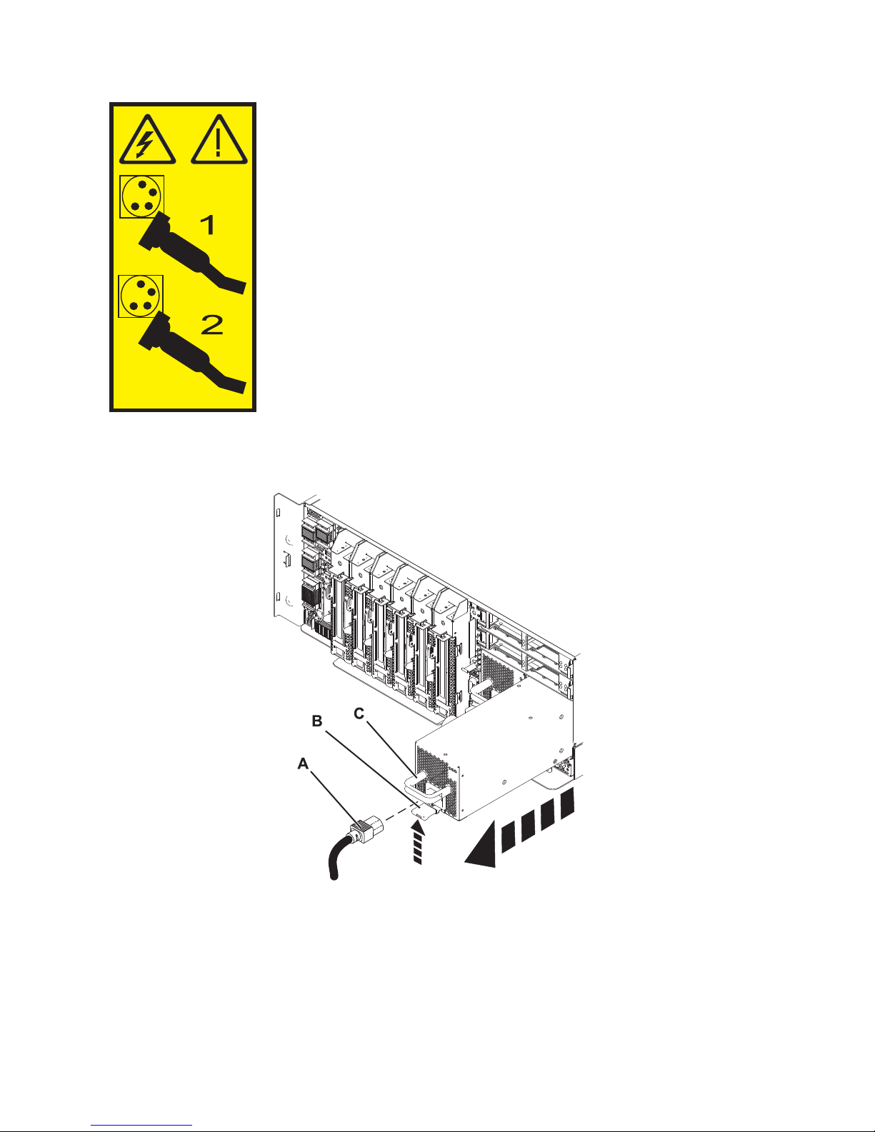
6. Lift the tab (B) toward the power cord retainer (C) to release the power supply. Pull the power supply
away from the system, as shown in Figure 1.
Figure 1. Removing the power supply
If you want to replace the power supply you removed, see “Replacing the 9117-MMB, 9117-MMC,
9179-MHB, or 9179-MHC power supply with the power turned off” on page 4.
2 Power Systems: Power supplies for the 9117-MMB, 9117-MMC, 9179-MHB, or 9179-MHC
Page 15

Removing the 9117-MMB, 9117-MMC, 9179-MHB, or 9179-MHC power
supply with the power turned on
Learn how to remove a power supply with the system power turned on if you want to replace a failing
power supply, or as a part of another service action.
Attention: Two power supplies must be present in the system to power on the system unit. If one power
supply fails, or you have a system failure that does not stop the fans, the system continues to operate.
You can remove and replace the power supply with the system power turned on if it is done in less than
5 minutes. After 5 minutes, the system turns off the power to prevent the system from overheating. If the
system power is turned off, go to “Removing the 9117-MMB, 9117-MMC, 9179-MHB, or 9179-MHC power
supply with the power turned off” on page 1.
If your system is managed by the Hardware Management Console (HMC), use the HMC to remove a
power supply. For instructions, see Removing a part by using the Hardware Management Console.
If your system is managed by the IBM Systems Director Management Console (SDMC), use the SDMC to
remove a power supply in the server. For instructions, see Removing a part by using the Systems
Director Management Console.
If your system is not managed by an HMC or SDMC, complete the following steps to remove a power
supply from a system while the system power is turned on:
1. Perform the prerequisite tasks, as described in Before you begin.
2. On a rack-mounted system unit, open the rear rack door.
3. Identify the failing part, as described in Identifying a failing part.
4. Disconnect the power source from the system by unplugging the system, as described in
Disconnecting the power cords.
5. Attach the wrist strap.
Attention:
v Attach a wrist strap to an unpainted metal surface of your hardware to prevent electrostatic
discharge (ESD) from damaging your hardware.
v When using a wrist strap, follow all electrical safety procedures. A wrist strap is for static control. It
does not increase or decrease your risk of receiving electric shock when using or working on
electrical equipment.
v If you do not have a wrist strap, just prior to removing the product from ESD packaging and
installing or replacing hardware, touch an unpainted metal surface of the system for a minimum of
5 seconds.
6. Lift the tab (B) toward the power cord retainer (C) to release the power supply. Pull the power supply
away from the system, as shown in Figure 2 on page 4.
Power supplies 3
Page 16
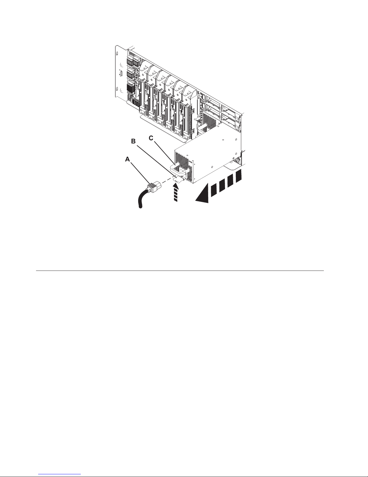
Figure 2. Removing the power supply
Note: When you remove a power supply with the system power turned on, an error is logged. No
action is required for this error.
If you want to replace the power supply you removed, see “Replacing the 9117-MMB, 9117-MMC,
9179-MHB, or 9179-MHC power supply with the power turned on” on page 6.
Replacing the 9117-MMB, 9117-MMC, 9179-MHB, or 9179-MHC power
supply with the power turned off
Learn how to replace a power supply with the system power turned off.
If your system is managed by the Hardware Management Console (HMC), use the HMC to replace a
power supply. For instructions, see Exchanging a part by using the Hardware Management Console.
If your system is managed by the IBM Systems Director Management Console (SDMC), use the SDMC to
replace a power supply in the server. For instructions, see Replacing a part by using the Systems Director
Management Console.
If your system is not managed by an HMC or SDMC, complete the following steps to replace a power
supply in a system while the system power is turned off:
1. To remove the power supply, see “Removing the 9117-MMB, 9117-MMC, 9179-MHB, or 9179-MHC
power supply with the power turned off” on page 1.
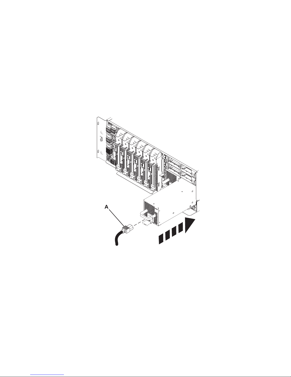
2. Align the power supply with the bay and slide the new power supply into the system until it locks in
place.
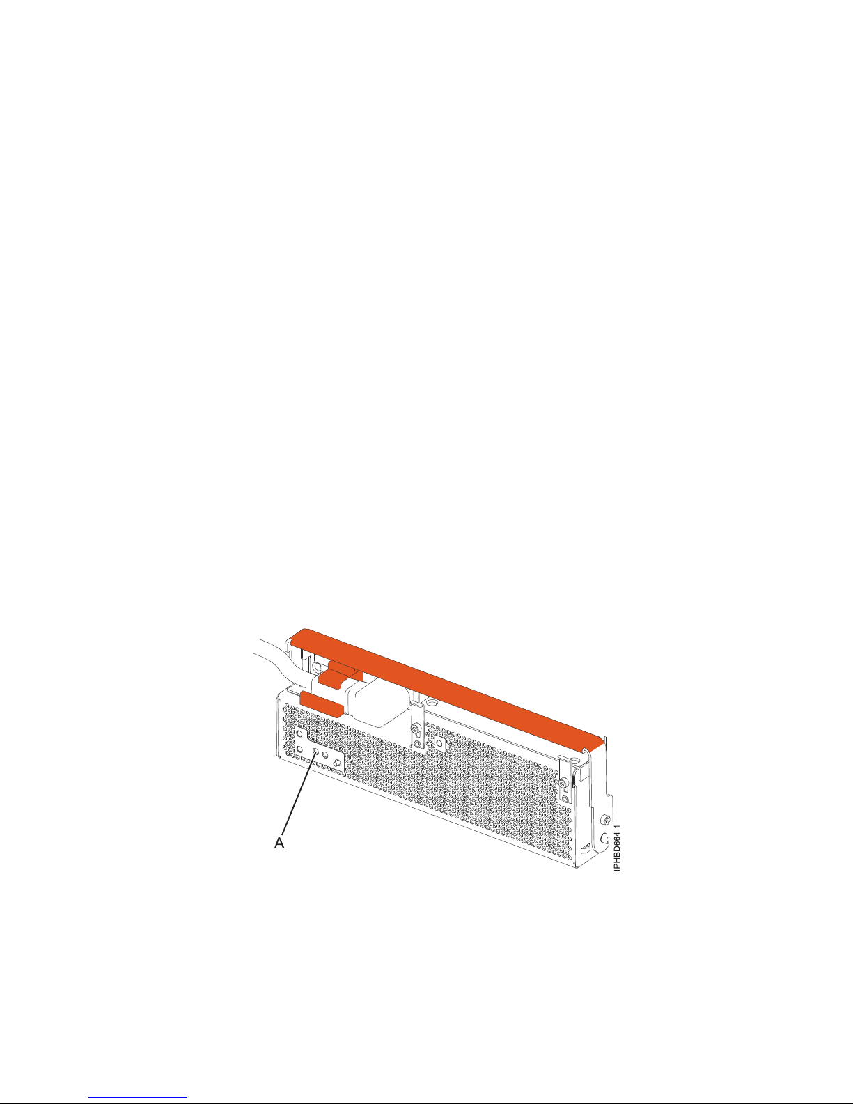
3. Connect the power cable A to the power supply.
4 Power Systems: Power supplies for the 9117-MMB, 9117-MMC, 9179-MHB, or 9179-MHC
Page 17
Note: This system is equipped with a second power supply. Before continuing with this procedure,
connect all power sources to the system.
Figure 3. Replacing a power supply
4. Start the system, as described in Starting the system or logical partition.
5. Note the state of the light-emitting diodes (LEDs) on the power supply. For more information, see
“Power supply LEDs” on page 8. If the LEDs indicate that the power supply is operating normally,
that is, the AC input LED and the DC output LED are on solid (not flashing) and the fault/identify
LED is flashing or off, continue to the next step. If not, remove the power supply from the system and
repeat the procedure starting with step 2 on page 4. If, after repeating the procedure, the power
supply is not operating normally, contact your service provider.
Figure 4. Power supply LEDs
Power supplies 5
Page 18
6. Close the rack door at the rear of the system.
Replacing the 9117-MMB, 9117-MMC, 9179-MHB, or 9179-MHC power
supply with the power turned on
Learn how to replace a power supply with the system power turned on.
Attention: Two power supplies must be present in the system to power on the system unit. If one power
supply fails, or you have a system failure that does not stop the fans, the system continues to operate.
You can remove and replace the power supply with the system power turned on if it is done in less than
5 minutes. After 5 minutes, the system turns off the power to prevent the system from overheating. If the
system power is turned off, go to “Replacing the 9117-MMB, 9117-MMC, 9179-MHB, or 9179-MHC power
supply with the power turned off” on page 4.
If your system is managed by the Hardware Management Console (HMC), use the HMC to replace a
power supply. For instructions, see Exchanging a part by using the Hardware Management Console.
If your system is managed by the IBM Systems Director Management Console (SDMC), use the SDMC to
replace a power supply in the server. For instructions, see Replacing a part by using the Systems Director
Management Console.
If your system is not managed by an HMC or SDMC, complete the following steps to replace a power
supply in a system while the system power is turned on:
1. To remove the power supply, see “Removing the 9117-MMB, 9117-MMC, 9179-MHB, or 9179-MHC
power supply with the power turned on” on page 3.
2. Perform the prerequisite tasks, as described in Before you begin.
3. Attach the wrist strap.
6 Power Systems: Power supplies for the 9117-MMB, 9117-MMC, 9179-MHB, or 9179-MHC
Page 19
Attention:
v Attach a wrist strap to an unpainted metal surface of your hardware to prevent electrostatic
discharge (ESD) from damaging your hardware.
v When using a wrist strap, follow all electrical safety procedures. A wrist strap is for static control. It
does not increase or decrease your risk of receiving electric shock when using or working on
electrical equipment.
v If you do not have a wrist strap, just prior to removing the product from ESD packaging and
installing or replacing hardware, touch an unpainted metal surface of the system for a minimum of
5 seconds.
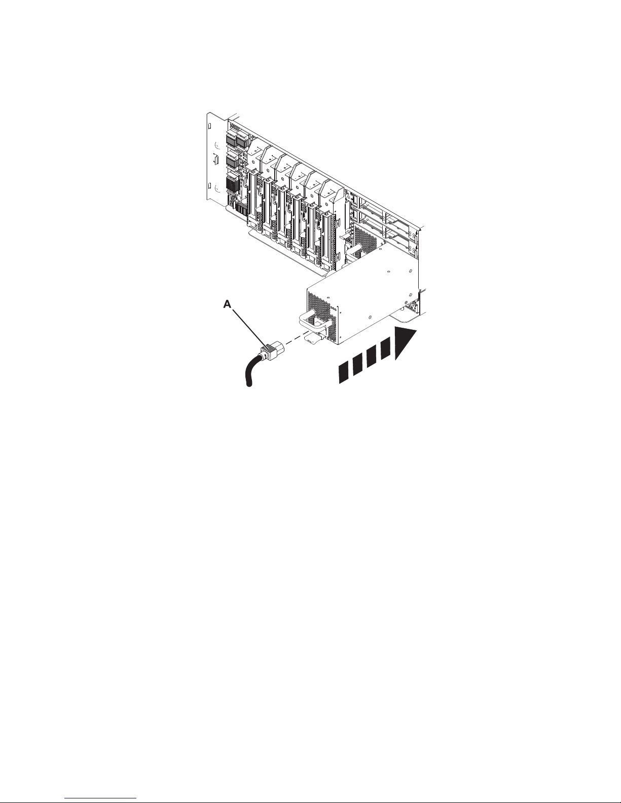
4. Align the power supply with the power supply bay and slide the power supply into the system until
it locks into place.
5. Attach the power cable (A), as shown in Figure 5.
Figure 5. Replacing the power supply
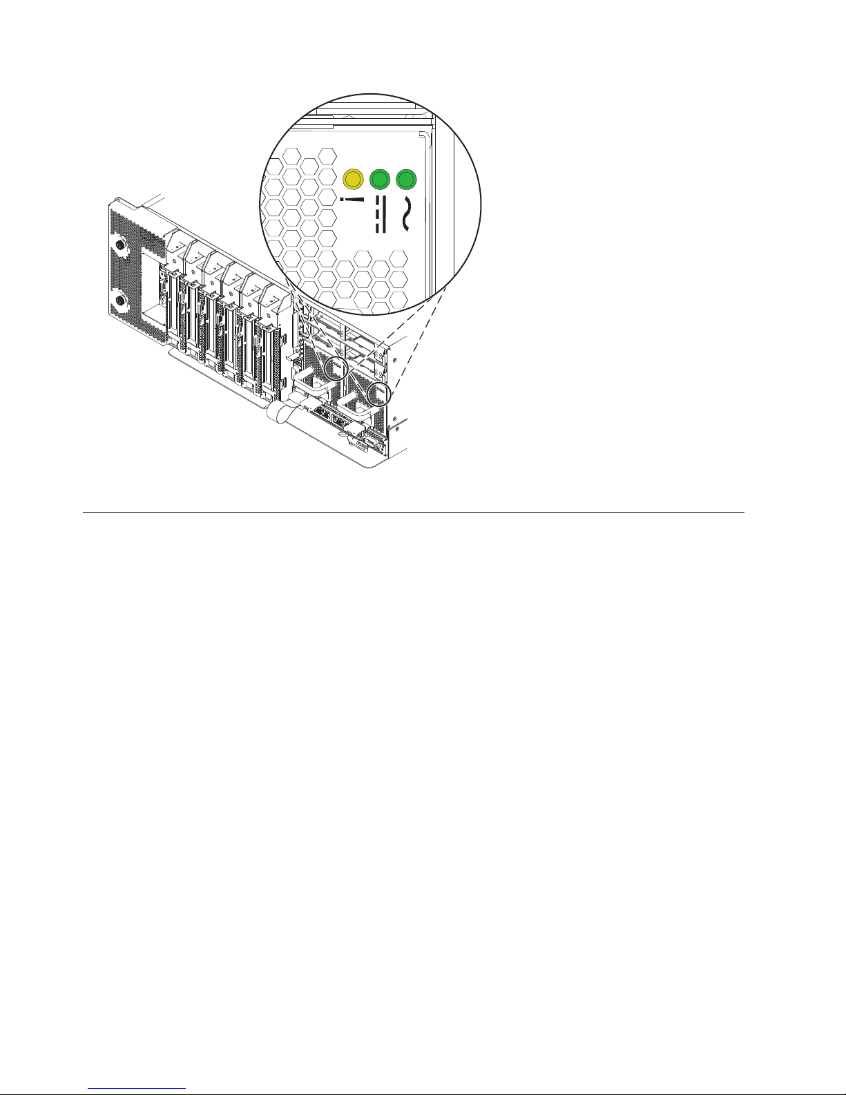
6. Note the state of the light-emitting diodes (LEDs) on the power supply. For more information, see
“Power supply LEDs” on page 8. If the LEDs indicate that the power supply is operating normally,
that is, the AC input LED and the DC output LED are on solid (not flashing) and the fault/identify
LED is flashing or off, continue to the next step. If not, remove the power supply from the system and
repeat the procedure starting with step 4. If, after repeating the procedure, the power supply is not
operating normally, contact your service provider.
Power supplies 7
Page 20
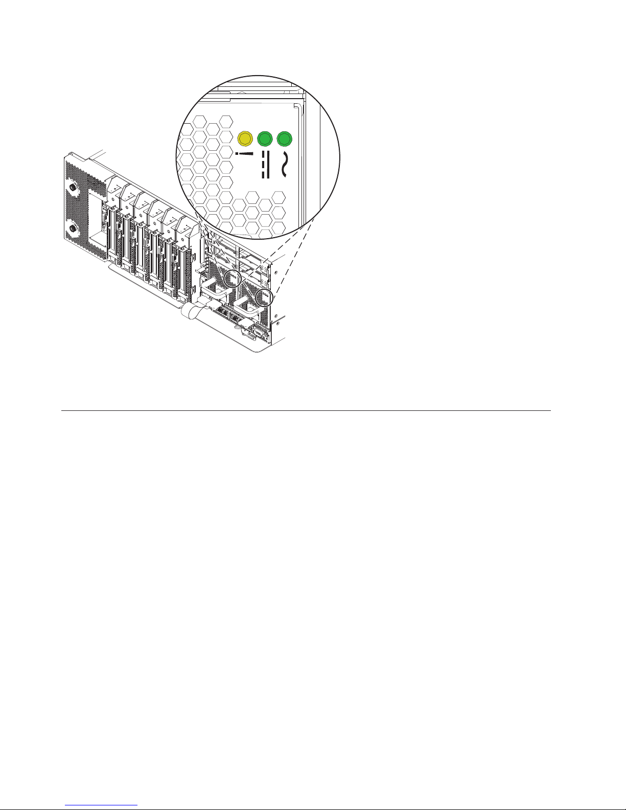
Figure 6. Power supply LEDs
7. Close the rack door at the rear of the system.
Power supply LEDs
The various states of the power supply light-emitting diodes (LEDs) can be used to identify or verify a
power supply that you are servicing.
The power supply has three LEDs that indicate the power supply status:
v an ac power LED (green, at the right of the 3 LEDs)
v a dc power LED (green, in the middle of the 3 LEDs)
v an error and identify function LED (amber, at the left of the 3 LEDs)
To locate the power supply LEDs, look on the top or at the back of an exposed power supply. You must
remove covers or panels to expose the power supply. Follow the instructions to remove covers or panels
for the power supply you are working with, and then return here.
To activate the identify function, see Identifying a failing part.
Descriptions for the states of the power supply LEDs follow:
v If both the ac power and dc power (green) LEDs are on solid (not flashing) and the error and identify
function (amber) LED is off, the power supply is operating correctly.
v If the ac power LED is on, the dc power LED is flashing, and the error and identify function (amber)
LED is off, then the system is turned off, but the power supply is still connected to the power source.
v If the error and identify function (amber) LED is flashing, the power supply identify function has been
selected.
v If the error and identify function (amber) LED is flashing, the ac power LED is on solid and the dc
power LED is off, the power supply is not operating correctly and has been identified for replacement.
8 Power Systems: Power supplies for the 9117-MMB, 9117-MMC, 9179-MHB, or 9179-MHC
Page 21

Power supplies, fans, and input power distribution assemblies in a
5802 or 5877 expansion unit
Learn about removing and replacing a power supply, fan, or input power distribution assembly to replace
a failing part or as part of another service action in a 5802 or 5877 expansion unit.
The power supply is located in an Offline Converter Assembly (OCA) in the 5802 expansion unit. The
expansion unit has two OCAs, with each OCA consisting of a power supply and two fans. To remove or
replace a failing fan, you must remove the affected power supply.
Removing a power supply or fan from a 5802 or 5877 expansion unit
with the power turned on
Learn how to remove a power supply or power-supply fan from a 5802 or 5877 expansion unit if you
need to replace a failing part with the power turned on.
If your system is managed by the Hardware Management Console (HMC), use the HMC to remove a
power supply. For instructions, see Removing a part by using the Hardware Management Console.
If your system is managed by the IBM Systems Director Management Console (SDMC), use the SDMC to
remove a power supply in the server. For instructions, see Removing a part by using the Systems
Director Management Console.
Determine if you are able to perform this procedure concurrently
Attention
Note: Two power supplies must be present in the expansion unit. If one power supply fails, the
expansion unit continues to operate. If you are performing this procedure concurrently (with the power
turned on), there is a time limit. From the moment the power supply is removed, the exchange of the
power supply must be completed in less than 5 minutes. If you cannot replace the power supply in less than
5 minutes, the I/O drawer automatically shuts down.
Read the following steps, but do not perform them yet. Then decide if you are ready (and able) to
complete this repair within 5 minutes.
1. Have the replacement power supply or fan ready.
2. Remove the power supply from the expansion unit.
3. Install the fan or fans into the power supply as required for the service procedure being performed.
4. Install the power supply into the enclosure.
Note: If you are replacing a midplane or a power supply, ensure that you only replace one of these parts
at a time. If a midplane and both power supplies are replaced at the same time, the enclosure vital
product data (VPD), which is present only in these entities, is lost. The enclosure VPD is the identity of
the 5802 or 5877 enclosure.
If your system is not managed by an HMC or an SDMC, complete the following steps to remove a power
supply or fan from an expansion unit or system while the system power is turned on:
1. Perform the prerequisite tasks, as described in Before you begin.
2. Open the front rack door.
3. Identify the failing part, as described in Identifying a failing part.
4. At the front of the expansion unit, identify the power supply that must be replaced. To identify the
power supply, observe the state of the amber field-replaceable unit (FRU) fault and identify
light-emitting diode (LED) (A) as shown in Figure 7 on page 10. A lit (flashing or on solid) LED
indicates the failing power supply.
Power supplies 9
Page 22
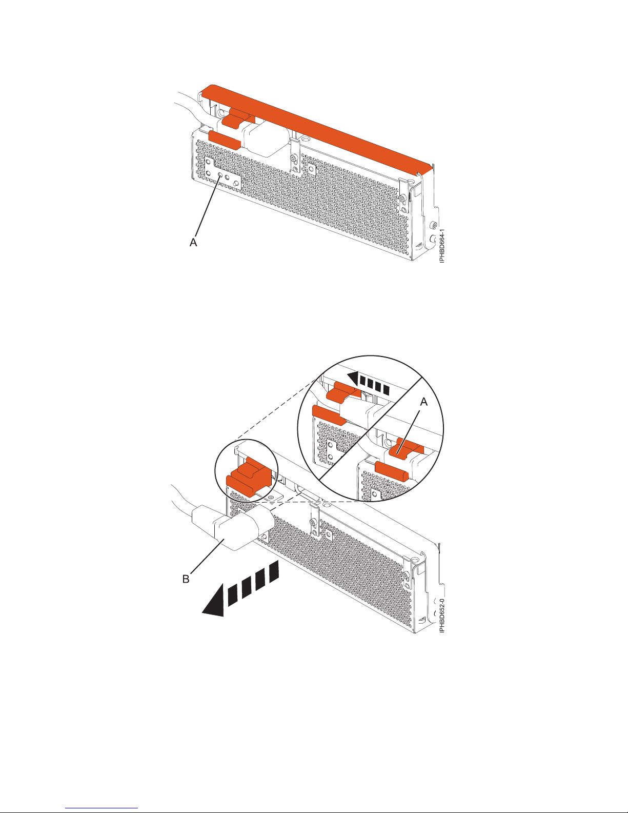
Figure 7. FRU fault and identify LED
5. For the power supply that you want to remove, slide the cable retention bracket to the open position
(A), and then disconnect the power cable (B) as shown in Figure 8. By moving the bracket to the
open position, you turn the power supply off.
Figure 8. Disconnecting the power cable from the front of an expansion unit
6. Attach the wrist strap.
10 Power Systems: Power supplies for the 9117-MMB, 9117-MMC, 9179-MHB, or 9179-MHC
Page 23
Attention:
v Attach a wrist strap to an unpainted metal surface of your hardware to prevent electrostatic
discharge (ESD) from damaging your hardware.
v When using a wrist strap, follow all electrical safety procedures. A wrist strap is for static control. It
does not increase or decrease your risk of receiving electric shock when using or working on
electrical equipment.
v If you do not have a wrist strap, just prior to removing the product from ESD packaging and
installing or replacing hardware, touch an unpainted metal surface of the system for a minimum of
5 seconds.
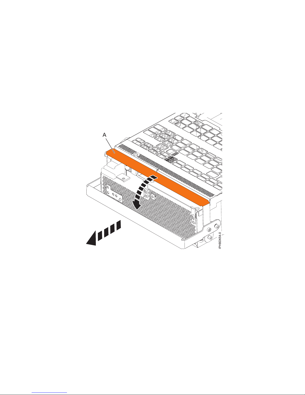
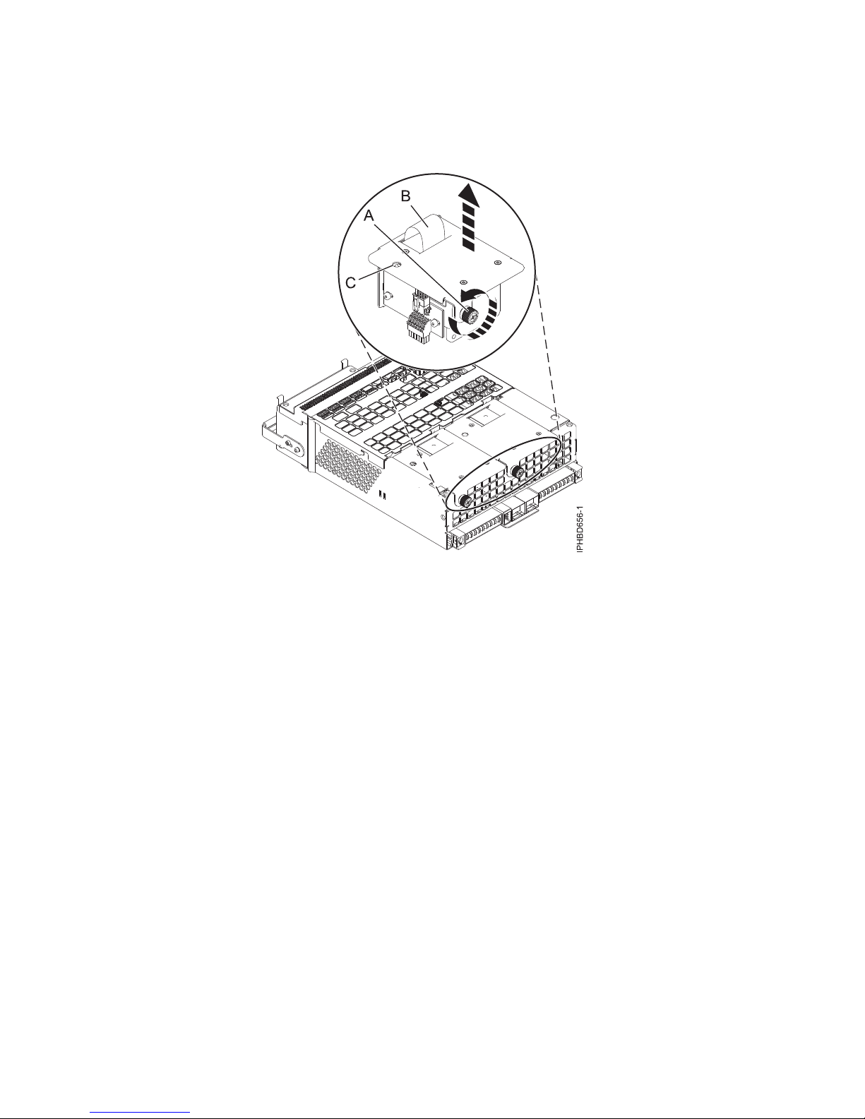
7. Rotate the power-supply locking handle (A) to the open position as shown in Figure 9. Pull the
power supply out of the expansion unit.
Figure 9. Removing a power supply
8. Optional: If you want to remove a failing power-supply fan, complete the following steps:
Note: If a fan fails, the amber fan fault LED (B) on the front of the Offline Converter Assembly
(OCA), as shown in Figure 10 on page 12, is on solid.
Power supplies 11
Page 24
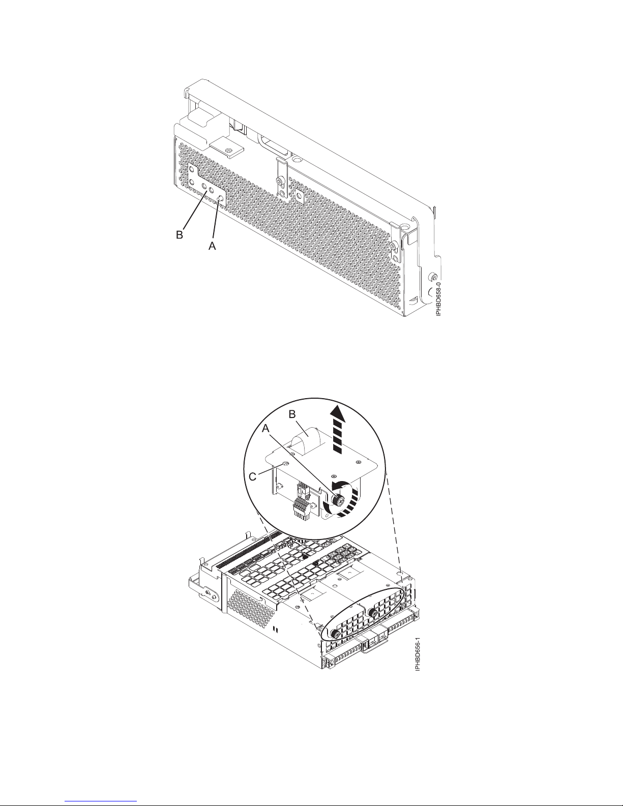
Figure 10. Fan fault LED and fan identify button
a. To identify the failing fan. Press the fan identify button (A), as shown in Figure 10. An amber
left or right fan-fault LED (C) on solid, as shown in Figure 11, indicates the faulty fan.
Figure 11. Removing a fan
b. Loosen the thumbscrew (A) that holds the fan in the power-supply assembly, as shown in
Figure 11.
12 Power Systems: Power supplies for the 9117-MMB, 9117-MMC, 9179-MHB, or 9179-MHC
Page 25
c. Use the recessed fan handle (B) to lift the fan from the power-supply assembly, as shown in
Figure 11 on page 12.
If you removed the power supply or fan as part of another service action, or if you want to replace the
power supply or fan that you removed from an expansion unit, see Replacing a power supply or fan in a
5802 or 5877 expansion unit with the power turned on.
Removing a power supply or fan from a 5802 or 5877 expansion unit
with the power turned off
Learn how to remove a power supply or power-supply fan from a 5802 or 5877 expansion unit if you
want to replace a failing part with the power turned off.
If your system is managed by the Hardware Management Console (HMC), use the HMC to remove a
power supply. For instructions, see Removing a part by using the Hardware Management Console.
If your system is managed by the IBM Systems Director Management Console (SDMC), use the SDMC to
remove a power supply in the server. For instructions, see Removing a part by using the Systems
Director Management Console.
If your system is not managed by an HMC or an SDMC, complete the following steps to remove a power
supply or fan from an expansion unit or system while the system power is turned off:
1. Perform the prerequisite tasks, as described in Before you begin.
2. Open the front rack door.
3. Identify the failing part, as described in Identifying a failing part.
4. At the front of the expansion unit, identify the power supply that needs to be replaced. To identify
the power supply, observe the state of the amber field-replaceable unit (FRU) fault and identify
light-emitting diode (LED) (A) as shown in Figure 12. A lit (on solid or flashing) LED indicates the
failing power supply.
Figure 12. FRU fault and identify LED
5. If the system is running, stop the system as described in Stopping the system or logical partition.
6. At the front of the expansion unit, slide the cable retention bracket for the power supply that you
want to remove, to the open position (A). Disconnect the cable (B) as shown in Figure 13 on page
14.
Power supplies 13
Page 26
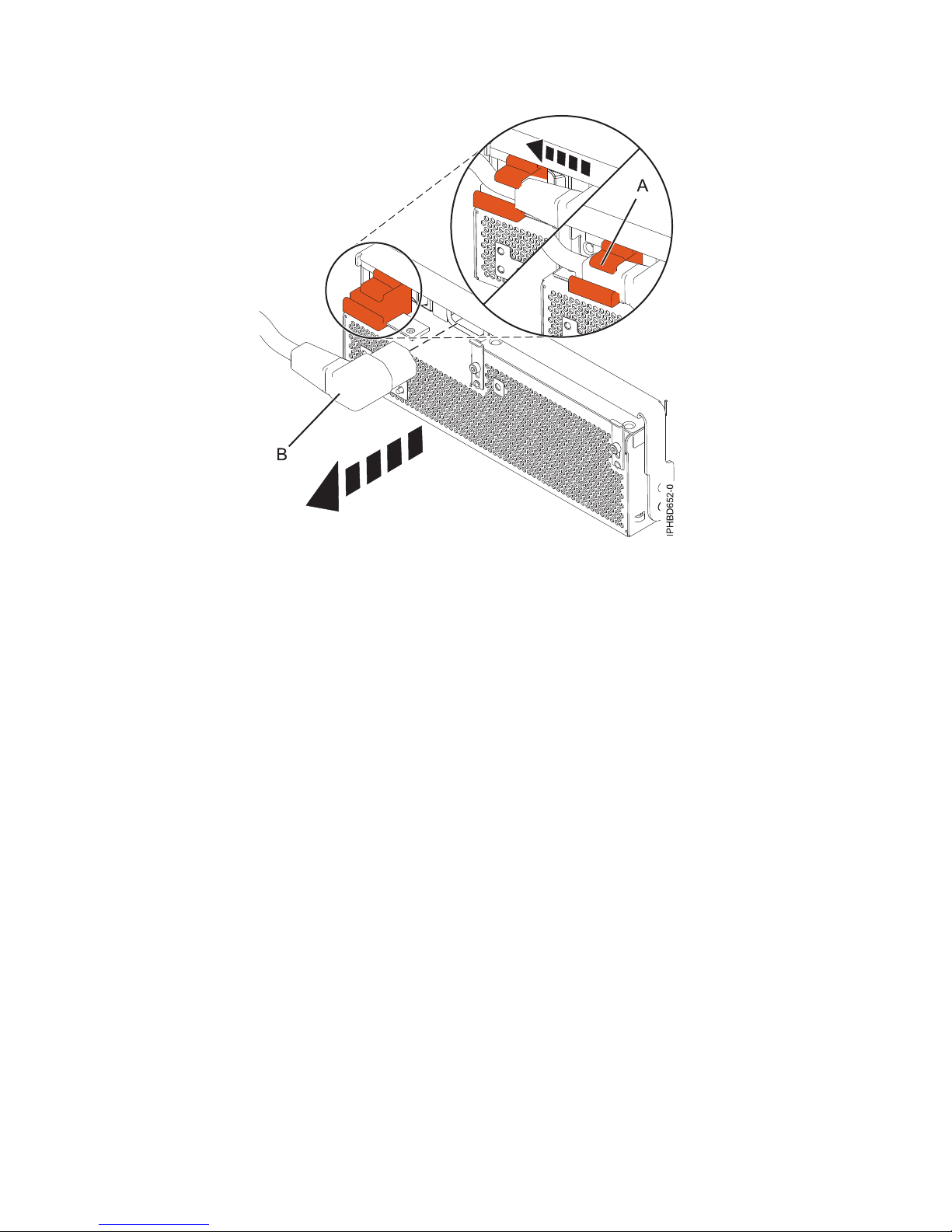
Figure 13. Disconnecting the power cable from the front of an expansion unit
7. Attach the wrist strap.
Attention:
v Attach a wrist strap to an unpainted metal surface of your hardware to prevent electrostatic
discharge (ESD) from damaging your hardware.
v When using a wrist strap, follow all electrical safety procedures. A wrist strap is for static control. It
does not increase or decrease your risk of receiving electric shock when using or working on
electrical equipment.
v If you do not have a wrist strap, just prior to removing the product from ESD packaging and
installing or replacing hardware, touch an unpainted metal surface of the system for a minimum of
5 seconds.
8. Rotate the power supply locking handle (A) to the open position, as shown in Figure 14 on page 15.
Pull out the power supply from the expansion unit.
14 Power Systems: Power supplies for the 9117-MMB, 9117-MMC, 9179-MHB, or 9179-MHC
Page 27
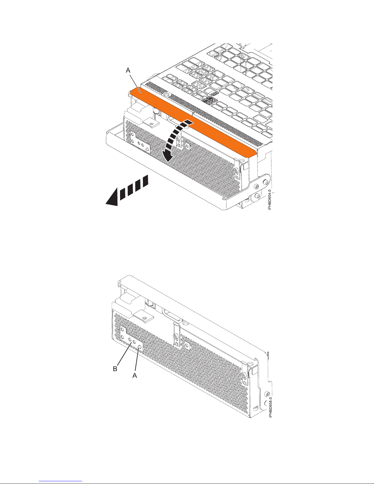
Figure 14. Removing a power supply
9. Optional: If you want to remove a failing power-supply fan, complete the following steps:
Note: If a fan fails, the amber fan fault LED on the front of the Offline Converter Assembly (OCA)
(B), shown in Figure 15, is on solid.
Figure 15. Fan fault LED and fan identify button
Power supplies 15
Page 28
a. Identify the failing fan by pressing the fan identify button (A) shown in Figure 15 on page 15.
An amber left or right fan-fault LED (C) on solid, as shown in Figure 16, indicates the faulty
fan.
Figure 16. Removing a power supply fan
b. Loosen the thumbscrew (A) that holds the fan in the power-supply assembly, as shown in
Figure 16.
c. Use the recessed fan handle (B) to pull the fan out of the power-supply assembly, as shown in
Figure 16.
If you removed the power supply or fan as part of another service action, or if you want to replace the
power supply or fan that you removed from the expansion unit, see “Replacing a power supply or fan in
a 5802 or 5877 expansion unit with the power turned off” on page 21.
Replacing a power supply or fan in a 5802 or 5877 expansion unit with
the power turned on
Learn how to replace a power supply or power-supply fan in a 5802 or 5877 expansion unit if you
removed a failing part and want to replace the power-supply assembly with the power turned on.
If your system is managed by the Hardware Management Console (HMC), use the HMC to replace a
power supply. For instructions, see Exchanging a part by using the Hardware Management Console.
If your system is managed by the IBM Systems Director Management Console (SDMC), use the SDMC to
replace a power supply in the server. For instructions, see Replacing a part by using the Systems Director
Management Console.
Determine if you are able to perform this procedure concurrently
16 Power Systems: Power supplies for the 9117-MMB, 9117-MMC, 9179-MHB, or 9179-MHC
Page 29

Attention: Two power supplies must be present in the expansion unit. If one power supply fails, the
expansion unit continues to operate. If you are performing this procedure concurrently (with the power
turned on), there is a time limit. From the moment the power supply is removed, the exchange of the
power supply must be completed in less than 5 minutes. If you cannot replace the power supply in less than
5 minutes, the I/O drawer automatically shuts down.
Before installing or reinstalling a power supply, inspect the signal connector pins to ensure that the pins
are not bent or damaged.
Attention: Bent pins damage the midplane receptacle. Be careful not to touch or damage the signal
connector pins.
Read the following steps, but do not perform them yet. Then decide if you are ready (and able) to
complete this repair within 5 minutes.
1. Have the replacement power supply or fan ready.
2. Remove the power supply from the expansion unit.
3. Install the fan or fans into the power supply as required for the service procedure being performed.
4. Install the power supply into the enclosure.
If your system is not managed by an HMC or an SDMC, complete the following steps to replace the
power supply in an expansion unit or system while the system power is turned on:
1. If you are replacing a power supply or power-supply fan because of a failure, remove the failing
part as described in Removing a power supply or fan from a 5802 or 5877 expansion unit with the
power turned on.
2. Perform the prerequisite tasks, as described in Before you begin.
3. Open the front rack door.
4. Attach the wrist strap.
Attention:
v Attach a wrist strap to an unpainted metal surface of your hardware to prevent electrostatic
discharge (ESD) from damaging your hardware.
v When using a wrist strap, follow all electrical safety procedures. A wrist strap is for static control.
It does not increase or decrease your risk of receiving electric shock when using or working on
electrical equipment.
v If you do not have a wrist strap, just prior to removing the product from ESD packaging and
installing or replacing hardware, touch an unpainted metal surface of the system for a minimum
of 5 seconds.
5. Optional: If you must replace a failing power-supply fan, complete the following steps:
a. Align the new fan with the opening in the power-supply assembly.
b. Press the fan (A) into its connector in the assembly as shown in Figure 17 on page 18.
c. Tighten the thumbscrew (D) as shown in Figure 17 on page 18.
Power supplies 17
Page 30
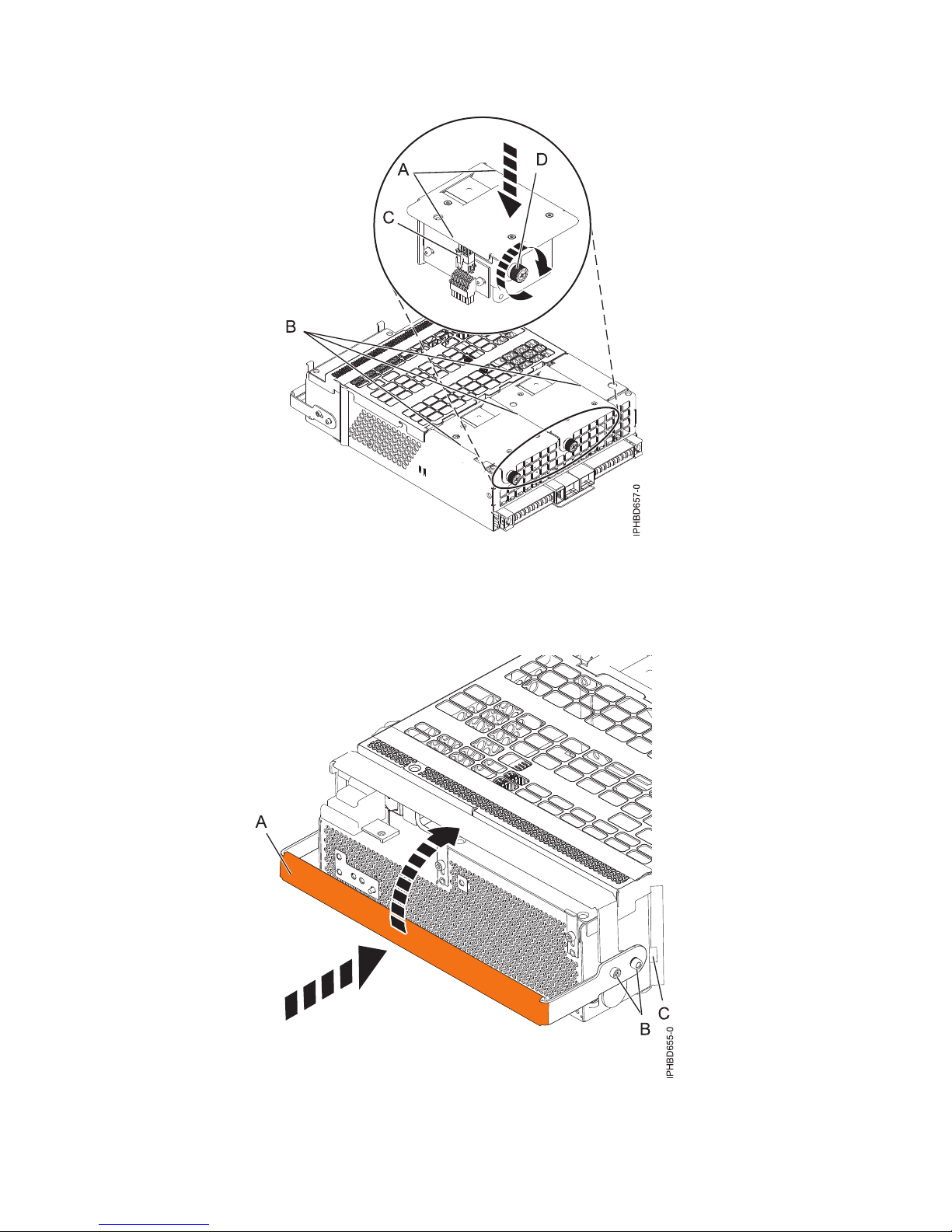
Figure 17. Replacing a fan
6. To replace the power supply, with the locking handle (A) in the open position, push the power
supply into the expansion unit as shown in Figure 18.
Figure 18. Replacing a power supply
7. Close the locking handle (A) until the power supply locks into position.
18 Power Systems: Power supplies for the 9117-MMB, 9117-MMC, 9179-MHB, or 9179-MHC
Page 31

8. Reconnect the power cable (A) to the front of the power supply, and then slide the cable retention
bracket (B) to the closed position to secure the cable as shown in Figure 19. By moving the bracket
to the closed position, you turn on the power supply.
Figure 19. Connecting the power cable to the front of an expansion unit
9. Note the state of the green ac power in (A) and Offline Converter Assembly (OCA) power (B)
light-emitting diodes (LEDs) shown in Figure 20 on page 20, and do one of the following actions, as
applicable:
v If the LEDs indicate that the power supply is operating normally, that is, that the ac power in LED
(A) is on solid and the OCA power (B) LED is on solid or flashing, continue to the next step.
v If not, remove the power supply from the expansion unit and repeat the procedure starting with
step 6 on page 18. If, after repeating the procedure, the power supply is not operating normally,
contact your service provider.
Power supplies 19
Page 32

Figure 20. Expansion unit ac power and OCA power LEDs
Note: If you replaced a power-supply fan as part of this procedure, note the state of the fan fault
LED (B) shown in Figure 21. If the LED is off, indicating that both fans are operating normally,
continue to the next step. If not, remove the power-supply assembly from the expansion unit and
repeat the procedure starting with step 5 on page 17. If, after repeating the procedure, the
power-supply fan is not operating normally, contact your service provider.
Figure 21. Fan fault LED
10. Verify the installed part, as described in Verifying the installed part.
11. Close the front rack door.
Continue with any other service actions you want to perform.
20 Power Systems: Power supplies for the 9117-MMB, 9117-MMC, 9179-MHB, or 9179-MHC
Page 33

Replacing a power supply or fan in a 5802 or 5877 expansion unit with
the power turned off
Learn how to replace a power supply or power-supply fan in a 5802 or 5877 expansion unit if you
removed a failing part and want to replace the power supply assembly with the power turned off.
If your system is managed by the Hardware Management Console (HMC), use the HMC to replace a
power supply. For instructions, see Exchanging a part by using the Hardware Management Console.
If your system is managed by the IBM Systems Director Management Console (SDMC), use the SDMC to
replace a power supply in the server. For instructions, see Replacing a part by using the Systems Director
Management Console.
If your system is not managed by an HMC or an SDMC, complete the following steps to replace the
power supply in an expansion unit or system while the system power is turned off:
1. If you are replacing a power supply or power-supply fan because of a failure, remove the failing
part as described in “Removing a power supply or fan from a 5802 or 5877 expansion unit with the
power turned off” on page 13.
2. Perform the prerequisite tasks, as described in Before you begin.
3. Open the front rack door if it is not already open.
4. Attach the wrist strap.
Attention:
v Attach a wrist strap to an unpainted metal surface of your hardware to prevent electrostatic
discharge (ESD) from damaging your hardware.
v When using a wrist strap, follow all electrical safety procedures. A wrist strap is for static control.
It does not increase or decrease your risk of receiving electric shock when using or working on
electrical equipment.
v If you do not have a wrist strap, just prior to removing the product from ESD packaging and
installing or replacing hardware, touch an unpainted metal surface of the system for a minimum
of 5 seconds.
5. Optional: If you want to replace a failing power-supply fan, complete the following steps:
a. Align the new fan with the opening in the power-supply assembly.
b. Press the fan (A) into its connector in the assembly, as shown in Figure 22 on page 22.
Power supplies 21
Page 34

Figure 22. Replacing a fan
c. Tighten the thumbscrew (D) as shown in Figure 22.
6. To replace the power supply, with the locking handle (A) in the open position, push the power
supply into the expansion unit as shown in Figure 23 on page 23.
7. Close the locking handle (A) until the power supply locks into position.
22 Power Systems: Power supplies for the 9117-MMB, 9117-MMC, 9179-MHB, or 9179-MHC
Page 35

Figure 23. Replacing a power supply
8. Connect the power cable (A) to the front of the power supply, and then slide the cable retention
bracket (B) to the closed position to secure the cable as shown in Figure 24.
Figure 24. Connecting the power cable to the front of an expansion unit
9. Start the system, as described in Starting the system or logical partition.
Power supplies 23
Page 36

10. Note the state of the green ac power in (A) and Offline Converter Assembly (OCA) power (B)
light-emitting diodes (LEDs) shown in Figure 25, and do one of the following actions, as applicable:
v If the LEDs indicate that the power supply is operating normally, that is, that the ac power in LED
(A) is on solid and the OCA power (B) LED is on solid or flashing, continue to the next step.
v If not, remove the power supply from the expansion unit and repeat the procedure starting with
step 6 on page 22. If, after repeating the procedure, the power supply is not operating normally,
contact your service provider.
Figure 25. Expansion unit ac power and OCA power LEDs
Note: If you replaced a power supply fan as part of this procedure, note the state of the fan fault
LED (B) shown in Figure 26 on page 25. If the LED is off, indicating that both fans are operating
normally, continue to the next step. If not, remove the power supply assembly from the expansion
unit and repeat the procedure starting with step 5 on page 21. If, after repeating the procedure, the
power supply fan is not operating normally, contact your service provider.
24 Power Systems: Power supplies for the 9117-MMB, 9117-MMC, 9179-MHB, or 9179-MHC
Page 37

Figure 26. Fan fault LED
11. Verify the installed part, as described in Verifying the installed part.
12. Close the front rack door.
Continue with any other service actions you need to perform.
Removing an input power distribution assembly from a 5802 or 5877
expansion unit with the power turned off
Learn how to remove an input power distribution assembly from a 5802 or 5877 expansion unit if you
must replace a failing assembly.
If your system is managed by the Hardware Management Console (HMC), use the HMC to remove an
input power distribution assembly. For instructions, see Removing a part by using the Hardware
Management Console.
If your system is managed by the IBM Systems Director Management Console (SDMC), use the SDMC to
complete the steps for removing a power supply in the server. For instructions, see Removing a part by
using the Systems Director Management Console.
To remove an input power distribution assembly from an expansion unit for a system that is not
managed by an HMC or an SDMC, complete the following steps:
1. Perform the prerequisite tasks, as described in Before you begin.
2. Identify the failing part, as described in Identifying a failing part.
3. If the system is running, stop the system as described in Stopping the system or logical partition.
4. Open the rear rack door.
5. At the rear of the expansion unit, disconnect both of the power cables, as shown in Figure 27 on page
26.
Power supplies 25
Page 38

Figure 27. Disconnecting the power cables from the rear of an expansion unit
6. Attach the wrist strap.
Attention:
v Attach a wrist strap to an unpainted metal surface of your hardware to prevent electrostatic
discharge (ESD) from damaging your hardware.
v When using a wrist strap, follow all electrical safety procedures. A wrist strap is for static control. It
does not increase or decrease your risk of receiving electric shock when using or working on
electrical equipment.
v If you do not have a wrist strap, just prior to removing the product from ESD packaging and
installing or replacing hardware, touch an unpainted metal surface of the system for a minimum of
5 seconds.
7. On the input power distribution assembly cover, loosen the thumbscrew (A), and then remove the
cover as shown in Figure 28 on page 27.
26 Power Systems: Power supplies for the 9117-MMB, 9117-MMC, 9179-MHB, or 9179-MHC
Page 39

Figure 28. Removing an input power distribution assembly cover
8. Loosen the thumbscrew (B) on the input power distribution assembly. Pull out the assembly from
the expansion unit, as shown in Figure 29.
Figure 29. Removing an input power distribution assembly
Power supplies 27
Page 40

To replace an input power distribution assembly, see “Replacing an input power distribution assembly in
a 5802 or 5877 expansion unit with the power turned off.”
Replacing an input power distribution assembly in a 5802 or 5877
expansion unit with the power turned off
Learn how to replace an input power distribution assembly in a 5802 or 5877 expansion unit if you
removed a failing assembly and must replace it.
If your system is managed by the Hardware Management Console (HMC), use the HMC to replace an
input power distribution assembly. For instructions, see Exchanging a part by using the Hardware
Management Console.
If your system is managed by the IBM Systems Director Management Console (SDMC), use the SDMC to
complete the steps for replacing a power supply in the server. For instructions, see Replacing a part by
using the Systems Director Management Console.
To replace an input power distribution assembly in an expansion unit for a system that is not managed
by an HMC or an SDMC, complete the following steps:
1. If you are replacing an input power distribution assembly because of a failure, remove the failing
part, as described in “Removing an input power distribution assembly from a 5802 or 5877
expansion unit with the power turned off” on page 25.
2. Perform the prerequisite tasks, as described in Before you begin.
3. Open the rear rack door.
4. Attach the wrist strap.
Attention:
v Attach a wrist strap to an unpainted metal surface of your hardware to prevent electrostatic
discharge (ESD) from damaging your hardware.
v When using a wrist strap, follow all electrical safety procedures. A wrist strap is for static control.
It does not increase or decrease your risk of receiving electric shock when using or working on
electrical equipment.
v If you do not have a wrist strap, just prior to removing the product from ESD packaging and
installing or replacing hardware, touch an unpainted metal surface of the system for a minimum
of 5 seconds.
5. Push the input power distribution assembly into the expansion unit until it latches into place, and
then tighten the thumbscrew (A) to secure the assembly in place as shown in Figure 30 on page
29.
28 Power Systems: Power supplies for the 9117-MMB, 9117-MMC, 9179-MHB, or 9179-MHC
Page 41

Figure 30. Replacing an input power distribution assembly
6. Replace the input power distribution assembly cover, and then tighten the thumbscrew (A) as
shown in Figure 31.
Figure 31. Replacing an input power distribution assembly cover
Power supplies 29
Page 42

7. At the rear of the expansion unit, connect both of the power cables, as shown in Figure 32.
Figure 32. Connecting the power cables at the rear of an expansion unit
8. Close the rear rack door.
9. Start the system, as described in Starting the system or logical partition.
10. Verify the installed part, as described in Verifying the installed part.
Continue with any other service actions you want to perform.
Replacing an input power distribution assembly in a 5802 or 5877
expansion unit with the power turned off
Learn how to replace an input power distribution assembly in a 5802 or 5877 expansion unit if you
removed a failing assembly and must replace it.
If your system is managed by the Hardware Management Console (HMC), use the HMC to replace an
input power distribution assembly. For instructions, see Exchanging a part by using the Hardware
Management Console.
If your system is managed by the IBM Systems Director Management Console (SDMC), use the SDMC to
complete the steps for replacing a power supply in the server. For instructions, see Replacing a part by
using the Systems Director Management Console.
To replace an input power distribution assembly in an expansion unit for a system that is not managed
by an HMC or an SDMC, complete the following steps:
1. If you are replacing an input power distribution assembly because of a failure, remove the failing
part, as described in “Removing an input power distribution assembly from a 5802 or 5877
expansion unit with the power turned off” on page 25.
2. Perform the prerequisite tasks, as described in Before you begin.
30 Power Systems: Power supplies for the 9117-MMB, 9117-MMC, 9179-MHB, or 9179-MHC
Page 43

3. Open the rear rack door.
4. Attach the wrist strap.
Attention:
v Attach a wrist strap to an unpainted metal surface of your hardware to prevent electrostatic
discharge (ESD) from damaging your hardware.
v When using a wrist strap, follow all electrical safety procedures. A wrist strap is for static control.
It does not increase or decrease your risk of receiving electric shock when using or working on
electrical equipment.
v If you do not have a wrist strap, just prior to removing the product from ESD packaging and
installing or replacing hardware, touch an unpainted metal surface of the system for a minimum
of 5 seconds.
5. Push the input power distribution assembly into the expansion unit until it latches into place, and
then tighten the thumbscrew (A) to secure the assembly in place as shown in Figure 30 on page
29.
Figure 33. Replacing an input power distribution assembly
6. Replace the input power distribution assembly cover, and then tighten the thumbscrew (A) as
shown in Figure 31 on page 29.
Power supplies 31
Page 44

Figure 34. Replacing an input power distribution assembly cover
7. At the rear of the expansion unit, connect both of the power cables, as shown in Figure 32 on page
30.
Figure 35. Connecting the power cables at the rear of an expansion unit
32 Power Systems: Power supplies for the 9117-MMB, 9117-MMC, 9179-MHB, or 9179-MHC
Page 45

8. Close the rear rack door.
9. Start the system, as described in Starting the system or logical partition.
10. Verify the installed part, as described in Verifying the installed part.
Continue with any other service actions you want to perform.
Common procedures for installable features
This section contains all the common procedures related to installing, removing and replacing features.
Before you begin
Observe these precautions when you are installing, removing, or replacing features and parts.
These precautions are intended to create a safe environment to service your system and do not provide
steps for servicing your system. The installation, removal and replacement procedures provide the
step-by-step processes required to service your system.
DANGER
When working on or around the system, observe the following precautions:
Electrical voltage and current from power, telephone, and communication cables are hazardous. To
avoid a shock hazard:
v Connect power to this unit only with the IBM provided power cord. Do not use the IBM
provided power cord for any other product.
v Do not open or service any power supply assembly.
v Do not connect or disconnect any cables or perform installation, maintenance, or reconfiguration
of this product during an electrical storm.
v The product might be equipped with multiple power cords. To remove all hazardous voltages,
disconnect all power cords.
v Connect all power cords to a properly wired and grounded electrical outlet. Ensure that the outlet
supplies proper voltage and phase rotation according to the system rating plate.
v Connect any equipment that will be attached to this product to properly wired outlets.
v When possible, use one hand only to connect or disconnect signal cables.
v Never turn on any equipment when there is evidence of fire, water, or structural damage.
v Disconnect the attached power cords, telecommunications systems, networks, and modems before
you open the device covers, unless instructed otherwise in the installation and configuration
procedures.
v Connect and disconnect cables as described in the following procedures when installing, moving,
or opening covers on this product or attached devices.
To Disconnect:
1. Turn off everything (unless instructed otherwise).
2. Remove the power cords from the outlets.
3. Remove the signal cables from the connectors.
4. Remove all cables from the devices
To Connect:
1. Turn off everything (unless instructed otherwise).
2. Attach all cables to the devices.
3. Attach the signal cables to the connectors.
4. Attach the power cords to the outlets.
5. Turn on the devices.
(D005)
Power supplies 33
Page 46

DANGER
Observe the following precautions when working on or around your IT rack system:
v Heavy equipment–personal injury or equipment damage might result if mishandled.
v Always lower the leveling pads on the rack cabinet.
v Always install stabilizer brackets on the rack cabinet.
v To avoid hazardous conditions due to uneven mechanical loading, always install the heaviest
devices in the bottom of the rack cabinet. Always install servers and optional devices starting
from the bottom of the rack cabinet.
v Rack-mounted devices are not to be used as shelves or work spaces. Do not place objects on top
of rack-mounted devices.
v Each rack cabinet might have more than one power cord. Be sure to disconnect all power cords in
the rack cabinet when directed to disconnect power during servicing.
v Connect all devices installed in a rack cabinet to power devices installed in the same rack
cabinet. Do not plug a power cord from a device installed in one rack cabinet into a power
device installed in a different rack cabinet.
v An electrical outlet that is not correctly wired could place hazardous voltage on the metal parts of
the system or the devices that attach to the system. It is the responsibility of the customer to
ensure that the outlet is correctly wired and grounded to prevent an electrical shock.
CAUTION
v Do not install a unit in a rack where the internal rack ambient temperatures will exceed the
manufacturer's recommended ambient temperature for all your rack-mounted devices.
v Do not install a unit in a rack where the air flow is compromised. Ensure that air flow is not
blocked or reduced on any side, front, or back of a unit used for air flow through the unit.
v Consideration should be given to the connection of the equipment to the supply circuit so that
overloading of the circuits does not compromise the supply wiring or overcurrent protection. To
provide the correct power connection to a rack, refer to the rating labels located on the
equipment in the rack to determine the total power requirement of the supply circuit.
v (For sliding drawers.) Do not pull out or install any drawer or feature if the rack stabilizer brackets
are not attached to the rack. Do not pull out more than one drawer at a time. The rack might
become unstable if you pull out more than one drawer at a time.
v (For fixed drawers.) This drawer is a fixed drawer and must not be moved for servicing unless
specified by the manufacturer. Attempting to move the drawer partially or completely out of the
rack might cause the rack to become unstable or cause the drawer to fall out of the rack.
(R001)
Before you begin a replacement or installation procedure, perform these tasks:
1. If you are installing a new feature, ensure that you have the software required to support the new
feature.
To do this, go to the following Web site: IBM Prerequisite
2. If you are performing an installation or replacement procedure that might put your data at risk,
ensure, wherever possible, that you have a current backup of your system or logical partition
(including operating systems, licensed programs, and data).
3. Review the installation or replacement procedure for the feature or part.
4. Note the significance of color on your system.
34 Power Systems: Power supplies for the 9117-MMB, 9117-MMC, 9179-MHB, or 9179-MHC
Page 47

Blue or terra-cotta on a part of the hardware indicates a touch point where you can grip the hardware
to remove it from or install it in the system, open or close a latch, and so on. Terra-cotta might also
indicate that the part can be removed and replaced with the system or logical partition power on.
5. Ensure that you have access to a medium flat-blade screwdriver, a Phillips screwdriver, and a pair of
scissors.
6. If parts are incorrect, missing, or visibly damaged, do the following:
v If you are replacing a part, contact the provider of your parts or next level of support.
v If you are installing a feature, contact one of the following service organizations:
– The provider of your parts or next level of support.
– In the United States, the IBM Rochester Manufacturing Automated Information Line (R–MAIL)
at 1–800–300–8751.
In countries and regions outside of the United States, use the following Web site to locate your service
and support telephone numbers:
http://www.ibm.com/planetwide
7. If you encounter difficulties during the installation, contact your service provider, your IBM reseller,
or your next level of support.
8. If you are installing new hardware in a logical partition, you need to understand and plan for the
implications of partitioning your system. For information, see Logical Partitioning.
Identifying a part
Use these instructions to learn how to identify the location of a failed part, the location of a part to be
removed, or the location to install a new part on your system or expansion unit using the appropriate
method for your system.
™
For IBM Power Systems
servers that contain the POWER7®processor, the light-emitting diodes (LEDs)
can be used to identify or verify the location of a part that you are removing, servicing, or installing.
The fault (amber) LED indicates an error and corresponds to the location code in the system reference
code (SRC). The LED is activated and deactivated automatically.
If you need to use the identify function, use the following procedures.
Control panel LEDs
Use this information as a guide to the control panel LEDs and buttons.
The control panel has LEDs that indicate various system status.
Power supplies 35
Page 48

Figure 36. Control panel
v A: Power-on button
v B: Power LED
– A constant light indicates full system power to the unit.
– A blinking light indicates standby power to the unit.
Note: There is approximately a 30-second transition period from the time the power-on button is
pressed to when the power LED goes from blinking to solid. During the transition period, the LED
might blink faster.
v C: Enclosure identify light
– A constant light indicates the identify state, which is used to identify a part.
– No light indicates that the system is operating normally.
v D: System information light
– No light indicates that the system is operating normally.
– Light on indicates that the system requires attention.
v E: USB port
v F: Enclosure fault roll-up light
– A constant light indicates a fault in the system unit.
– No light indicates that the system is operating normally.
v G: Function/Data display
v H: Decrement button
v I: Enter button
v J: Increment button
v K: Pinhole reset button
36 Power Systems: Power supplies for the 9117-MMB, 9117-MMC, 9179-MHB, or 9179-MHC
Page 49

Related concepts
Identifying a failing part
Use these instructions to learn how to locate and identify a failing part on your system or expansion unit
using the appropriate method for your system.
Identifying a failing part in an AIX system or logical partition
Use these instructions to learn how to locate a failing part, and then activate the indicator light for that
part on a system or logical partition running the AIX
Locating a failing part in an AIX system or logical partition:
You might need to use AIX tools, before activating the indicator light, to locate a part that is failing.
1. Log in as root user or celogin-.
2. At the command line, type diag and press Enter.
3. From the Function Selection menu, select Task Selection and press Enter.
4. Select Display Previous Diagnostic Results and press Enter.
5. From the Display Previous Diagnostic Results display, select Display Diagnostic Log Summary. The
Display Diagnostic Log display shows a chronological list of events.
6. Look in the T column for the most recent S entry. Select this row in the table and press Enter.
7. Select Commit. The details of this log entry are shown.
8. Record the location information and the SRN value shown near the end of the entry.
9. Exit to the command line.
®
operating system.
Use the location information for the failing part to activate the indicator light that identifies the failing
part. “Activating the indicator light for the failing part.”
Activating the indicator light for the failing part:
Use these instructions to help physically identify the location of a part you are servicing.
1. Log in as root user.
2. At the command line, type diag and press Enter.
3. From the Function Selection menu, select Task Selection and press Enter.
4. From the Task Selection menu, select Identify and Attention Indicators and press Enter.
5. From the list of lights, select the location code for the failing part and press Enter.
6. Select Commit. This turns on the system attention and indicator light for the failing part.
7. Exit to the command line.
Deactivating the failing-part indicator light:
Use this procedure to turn off any indicator light that you turned on as a part of a service action.
To deactivate the indicator light, follow these steps:
1. Log in as root user.
2. At the command line, type diag and press Enter.
3. From the Function Selection menu, select Task Selection and press Enter.
4. From the Task Selection menu, select Identify and Attention Indicators and press Enter.
5. From the list of lights, select the location code for the failing part and press Enter. When a light is
activated for a failing part, an I character precedes the location code.
6. Select Commit. This turns off the system attention and indicator light for the failing part.
7. Exit to the command line.
Power supplies 37
Page 50

Identifying a failing part in an IBM i system or logical partition
You can activate or deactivate the indicator light by using IBM i to assist in locating a failing part.
Identifying a failing part in a Linux system or logical partition
If the service aids have been installed on a system or logical partition, you can activate or deactivate the
indicator lights to locate a part or compete a service action.
Locating a failing part in a Linux system or logical partition:
If the service aids have been installed on a system or logical partition, you need to activate the indicator
lights to locate a part.
To activate the indicator light, follow these steps:
1. Log in as root user.
2. At the command line, type /usr/sbin/usysident -s identify -l<location code> and press Enter.
3. Look for the system attention light to identify the enclosure that contains the failing part.
Related information
Service and productivity tools for Linux on POWER systems
IBM provides hardware diagnostic aids and productivity tools, as well as installation aids for Linux
operating systems on IBM Power systems.
Finding the location code of a failing part in a Linux system or logical partition:
To retrieve the location code of the failing part, if you do not know the location code, use the procedure
in this topic.
To locate the failing part in a system or logical partition follow these steps:
1. Log in as root user.
2. At the command line, type grep diagela /var/log/platform and press Enter.
3. Look for the most recent entry that contains a system reference code (SRC).
4. Record the location information.
Note: IBM provides hardware diagnostic aids and productivity tools, as well as installation aids for
Linux operating systems on IBM Power systems. See Service and productivity tools for Linux on
Power Systems servers
Activating the indicator light for the failing part:
If you know the location code of the failing part, activate the indicator light to help you locate which part
to replace.
To activate the indicator light, follow these steps:
1. Log in as root user.
2. At the command line, type /usr/sbin/usysident -s identify -l<location code> and press Enter.
3. Look for the system attention light to identify the enclosure that contains the failing part.
Note: IBM provides hardware diagnostic aids and productivity tools, as well as installation aids for
Linux operating systems on IBM Power systems. See Service and productivity tools for Linux on Power
Systems servers
Deactivating the failing-part indicator light:
38 Power Systems: Power supplies for the 9117-MMB, 9117-MMC, 9179-MHB, or 9179-MHC
Page 51

After you complete a removal and replacement procedure, you must deactivate the failing-part indicator
light.
To deactivate the indicator light, follow these steps:
1. Log in as root user.
2. At the command line, type /usr/sbin/usysident -s normal -l<location code> and press Enter.
Note: IBM provides hardware diagnostic aids and productivity tools, as well as installation aids for
Linux operating systems on IBM Power systems. See Service and productivity tools for Linux on Power
Systems servers
Locating a failing part in a Virtual I/O Server system or logical partition
You can use Virtual I/O Server (VIOS) tools, before activating the indicator light, to locate a part that is
failing.
1. Log in as root user or celogin-.
2. At the command line, type diagmenu and press Enter.
3. From the Function Selection menu, select Task Selection and press Enter.
4. Select Display Previous Diagnostic Results and press Enter.
5. From the Display Previous Diagnostic Results display, select Display Diagnostic Log Summary.A
Display Diagnostic Log display appears. This display contains a chronological list of events.
6. Look in the T column for the most recent S entry. Select this row in the table and press Enter.
7. Choose Commit. The details of this log entry are shown.
8. Record the location information and the SRN value shown near the end of the entry.
9. Exit to the command line.
Use the location information for the failing part to activate the indicator light that identifies the failing
part. For instructions, see “Identifying a part by using the Virtual I/O Server.”
Identifying a part by using the Virtual I/O Server:
Use these instructions to turn on the indicator light to help you physically locate a part by using the
Virtual I/O Server (VIOS).
1. Log in as root user.
2. At the command line, type diagmenu and press Enter.
3. From the Function Selection menu, select Task Selection. Press Enter.
4. From the Task Selection menu, select Identify and Attention Indicators. Press Enter.
5. From the list of lights, select the location code for the failing part and press Enter.
6. Select Commit. This turns on the system attention and indicator light for the failing part.
7. Exit to the command line.
Starting the system or logical partition
Learn how to start a system or logical partition after performing a service action or system upgrade.
Starting a system that is not managed by an HMC or an SDMC
You can use the power button or the Advanced System Management Interface to start a system that is
not managed by a Hardware Management Console or an IBM Systems Director Management Console.
To start a system that is not managed by a Hardware Management Console (HMC) or Systems Director
Management Console (SDMC), follow these steps:
1. Open the front rack door, if necessary.
Power supplies 39
Page 52

2. Before you press the power button on the control panel, ensure that power is connected to the system
unit as follows:
v All system power cables are connected to a power source.
v The Power LED, as shown in the following figure, is slowly blinking.
v The top of the display, as shown in the following figure, shows 01 V=F.
3. Press the power button (A), as shown in the following figure, on the control panel.
Figure 37. Control panel
v A: Power-on button
v B: Power LED
– A constant light indicates full system power to the unit.
– A blinking light indicates standby power to the unit.
Note: There is approximately a 30-second transition period from the time the power-on button is
pressed to when the power LED goes from blinking to solid. During the transition period, the LED
might blink faster.
v C: Enclosure identify light
– A constant light indicates the identify state for the enclosure or for a resource within the
enclosure.
– No light indicates that no resources in the enclosure are being identified.
v D: Attention light
– No light indicates that the system is operating normally.
– A solid light indicates that the system requires attention.
v E: USB port
v F: Enclosure fault roll-up light
– A constant light indicates a fault indicator active in the system.
– No light indicates that the system is operating normally.
v G: Function/Data display
40 Power Systems: Power supplies for the 9117-MMB, 9117-MMC, 9179-MHB, or 9179-MHC
Page 53

v H: Decrement button
v I: Enter button
v J: Increment button
v K: Pinhole reset button
4. Observe the following after pressing the power button:
v The power-on light begins to blink faster.
v The system cooling fans are activated after approximately 30 seconds and begin to accelerate to
operating speed.
v Progress indicators, also referred to as checkpoints, appear on the control panel display while the
system is being started. The power-on light on the control panel stops blinking and remains on,
indicating that system power is on.
Tip: If pressing the power button does not start the system, do the following steps to start the system
using the Advanced System Management Interface (ASMI):
1. Access the ASMI. For instructions, see Accessing the ASMI.
2. Start the system using the ASMI. For instructions, see Powering the system on and off.
Starting a system or logical partition by using the Hardware Management Console
You can use the Hardware Management Console (HMC) user interface to start the system or logical
partition after the required cables are installed and the power cables are connected to a power source.
For instructions on working with the HMC, see Managing the Hardware Management Console. For
instructions on starting a logical partition, see Logical partitioning. For instructions on starting the
system, see Powering on the managed system.
Progress indicators, also referred to as checkpoints, appear on the control panel display while the system
is being started. When the power-on light on the control panel stops blinking and remains on, the system
power is on.
Starting a system or virtual server with the Systems Director Management Console
You can use the IBM Systems Director Management Console (SDMC) user interface to start the system or
virtual server after the required cables are installed and the power cables are connected to a power
source.
For instructions on working with the SDMC, see Managing and configuring the SDMC. For instructions
on starting a virtual server, see Managing virtual servers. For instructions on shutting down and
restarting virtual servers, see Shutting down and restarting virtual servers.
Progress indicators, also known as checkpoints, display on the control panel while the system is being
started. When the power-on light on the control panel stops flashing and remains on, the system power is
on.
Stopping a system or logical partition
Learn how to stop a system or logical partition as a part of a system upgrade or service action.
Attention: Using either the power-on button on the control panel or entering commands at the
Hardware Management Console (HMC) to stop the system can cause unpredictable results in the data
files. Also, the next time you start the system, it might take longer if all applications are not ended before
stopping the system.
To stop the system or logical partition, select the appropriate procedure.
Power supplies 41
Page 54

Stopping a system that is not managed by an HMC or an SDMC
You might need to stop the system to perform another task. Use these instructions to stop the system
using the power button or Advanced System Management Interface.
Before you stop the system, follow these steps:
®
1. If an Integrated xSeries
2. Ensure that all jobs are completed and end all applications.
3. Ensure that the operating system is stopped.
Attention: Failure to do so can result in the loss of data.
4. If a Virtual I/O Server (VIOS) logical partition is running, ensure that all clients are shut down or that
the clients have access to their devices using an alternate method.
The following procedure describes how to stop a system that is not managed by a Hardware
Management Console (HMC).
1. Log in to the system as a user with the authority to run the shutdown or pwrdwnsys (Power Down
System) command.
2. At the command line, enter one of the following commands:
v If your system is running the AIX operating system, type shutdown.
v If your system is running the Linux operating system, type shutdown -h now.
v If your system is running the IBM i operating system, type PWRDWNSYS. If your system is partitioned,
use the PWRDWNSYS command to power down each of the secondary partitions. Then, use the
PWRDWNSYS command to power down the primary partition.
The command stops the operating system. The system power turns off, the power-on light begins to
slowly flash, and the system goes into a standby state.
3. Record the IPL type and the IPL mode from the control panel display to help you return the system
to this state when the installation or replacement procedure is completed.
4. Set the power switches of any devices connected to the system to off.
5. Unplug any power cables that are attached to the unit from electrical outlets. Ensure that you unplug
power cables from peripheral devices, such as printers and expansion units.
Adapter (IXA) is present on the system, shut it down using IBM i options.
Important: The system is equipped with a second power supply. Before continuing with this
procedure, ensure that all power sources to the system have been disconnected.
(L003)
or
42 Power Systems: Power supplies for the 9117-MMB, 9117-MMC, 9179-MHB, or 9179-MHC
Page 55

Stopping a system by using the Hardware Management Console
You can use the Hardware Management Console (HMC) user interface to stop the system or a logical
partition.
By default, the managed system is set to power off automatically when you shut down the last running
logical partition on the managed system. If you set the managed system properties on the HMC so that
the managed system does not power off automatically, you must use this procedure to power off your
managed system.
Attention: If possible, shut down the running logical partitions on the managed system before powering
off the managed system. Powering off the managed system without shutting down the logical partitions
first causes the logical partitions to shut down abnormally and can cause data loss. If you use a Virtual
I/O Server (VIOS) logical partition, ensure that all clients are shut down or that the clients have access to
their devices using an alternate method.
To power off a managed system, you must be a member of one of the following roles:
v Super administrator
v Service representative
v Operator
v Product engineer
Use the following steps to stop the system using the HMC.
1. In the Navigation area, expand the Systems Management folder.
2. Click the Servers icon.
3. In the Contents area, select the managed system.
4. Select Tasks, then Operations, and then Power Off
5. Select the appropriate power-off mode and click OK.
Related information
Shutting down and restarting logical partitions
Stopping a system with the Systems Director Management Console
You can use the IBM Systems Director Management Console (SDMC) user interface to stop the system or
a virtual server.
Power supplies 43
Page 56

By default, the managed system is set to power off automatically when you shut down the last running
virtual server on the managed system. If you set the managed system properties on the SDMC so that the
managed system does not power off automatically, you must use this procedure to power off your
managed system.
Attention: If possible, shut down the running virtual servers on the managed system before powering
off the managed system. Powering off the managed system without shutting down the virtual servers
first causes the virtual servers to shut down abnormally and can cause data loss. If you use a Virtual I/O
Server (VIOS) logical partition, ensure that all clients are shut down or that the clients have access to
their devices with an alternate method.
To power off a managed system, you must be a member of one of the following roles:
v Super administrator
v Service representative
v Operator
v Product engineer
Use the following steps to stop the system using the SDMC.
1. In the Power Systems Resource area, select the managed system you want to power off.
2. From the Actions menu, select Operations → Power Off.
3. Select the appropriate power-off mode and click OK.
Placing the 8202-E4B, 8202-E4C, 8205-E6B, or 8205-E6C system into
the service or operating position
Use these procedures to place a system into the service position or operating position to perform service
or to gain access to internal components.
Placing a rack-mounted 8202-E4B, 8202-E4C, 8205-E6B, or 8205-E6C system into
the service position
Use this procedure to place the rack-mounted system into the service position.
Notes:
v When placing the system into the service position, it is essential that all stability plates are firmly in
position to prevent the rack from toppling. Ensure that only one system unit is in the service position
at a time.
v Ensure that the cables at the back of the system unit do not catch or bind as you pull the unit forward
in the rack.
v When the system unit rails are fully extended, the rail safety latches lock into place. This action
prevents the system from being pulled out too far.
1. Open the front rack door.
2. Identify the system unit you are servicing in the rack.
3. Remove the two screws (A) (if present) that secure the system unit (B) to the rack.
Note: Replacing the shipping screws is optional but should be done in geographic areas that are
prone to seismic activity.
44 Power Systems: Power supplies for the 9117-MMB, 9117-MMC, 9179-MHB, or 9179-MHC
Page 57

Figure 38. Placing the system in the service position
4. While holding the system unit release latches (A) down on both the left and right sides, pull the
system unit (B) out from the rack until the rails are fully extended and locked.
Placing the rack-mounted 8202-E4B, 8202-E4C, 8205-E6B, or 8205-E6C system into
the operating position
Use this procedure to place the rack-mounted system into the operating position.
Power supplies 45
Page 58

When placing the system into operating position, ensure that the cables at the back of the system do not
catch or bind as you push the system unit back into the rack.
1. Unlock the blue rail safety latches (A) by lifting them upwards. The rail safety latches are located near
the middle of the system.
Figure 39. Placing the system into the operating position
2. Push the system unit (B) back into the rack until both system-unit release latches have locked into
position.
3. Replace and tighten the two screws (if present) (A) that secure the system unit (B) to the rack.
Note: Replacing the two shipping screws is optional but should be done in geographic areas that are
prone to seismic activity.
4. Close the front rack door of the unit you are servicing.
46 Power Systems: Power supplies for the 9117-MMB, 9117-MMC, 9179-MHB, or 9179-MHC
Page 59

Figure 40. Placing the system into the operating position
Removing and replacing covers for the 8202-E4B, 8202-E4C, 8205-E6B,
or 8205-E6C
Use these instructions to remove, replace, or install covers to access components or perform service.
Removing the front cover on a rack-mounted 8202-E4B, 8202-E4C, 8205-E6B, or
8205-E6C system
Use this procedure to remove the cover to access components or perform service.
To remove the front cover, follow these steps:
1. Remove the two shipping screws (if present) that secure the system to the rack.
Note: Replacing the shipping screws is optional but should be done in geographic areas that are
prone to seismic activity.
2. Pull the cover away from the system. The cover has an indentation where you can hold onto it more
easily.
Power supplies 47
Page 60

Figure 41. Removing the front cover
Removing the front cover on a stand-alone 8202-E4B, 8202-E4C, 8205-E6B, or
8205-E6C system
Use this procedure to remove the cover to access components or perform service.
To remove the front cover, follow these steps:
1. Open the front door (A) by swinging it towards the left as shown in the following figure.
2. Press latch (B) and pull the cover away from the system. The cover has an indentation where you can
hold onto it more easily.
48 Power Systems: Power supplies for the 9117-MMB, 9117-MMC, 9179-MHB, or 9179-MHC
Page 61

Figure 42. Removing the front cover
Installing the front cover on a rack-mounted 8202-E4B, 8202-E4C, 8205-E6B, or
8205-E6C system
Use this procedure to install the cover to access components or perform service.
To install the front cover, follow these steps:
1. Push the cover onto the system.
2. Gently push the cover in until the four cover clips are seated in their respective mounting posts as
shown in the following figure. The cover snaps into place and has an indentation where you can hold
onto it more easily.
Note: Replacing the shipping screws is optional but should be done in geographic areas that are
prone to seismic activity.
Power supplies 49
Page 62

Figure 43. Removing the front cover
Installing the front cover and front door on a stand-alone 8202-E4B, 8202-E4C,
8205-E6B, or 8205-E6C system
Use this procedure to install the cover to access components or perform service.
To install the front cover and front door, complete the following steps.
1. Align the cover (A) until the two cover tabs are seated into the slots on the base plate (B), as shown
in the following figure.
2. Rotate the cover up and towards the system until the release latch is seated into its respective slot.
The cover has an indentation where you can hold onto it more easily.
50 Power Systems: Power supplies for the 9117-MMB, 9117-MMC, 9179-MHB, or 9179-MHC
Page 63

Figure 44. Installing the front cover
3. Hold the front door at an approximate 120 degree angle to the system as show in the following figure.
Engage the latches.
Figure 45. Installing the front door
Removing the service access cover on a rack-mounted 8202-E4B, 8202-E4C,
8205-E6B, or 8205-E6C system
Use this procedure to remove the service access cover.
1. Loosen the two thumbscrews (A) located at the back of the cover.
2. Slide the cover toward the back of the system unit. When the front of the service access cover has
cleared the upper frame ledge, lift the cover up and off the system unit.
Power supplies 51
Page 64

Attention: When the service access cover is removed, the system powers down.
Figure 46. Removing the service access cover
Removing the service access cover on a stand-alone 8202-E4B, 8202-E4C,
8205-E6B, or 8205-E6C system
Use this procedure to remove the service access cover.
1. Loosen the thumbscrew (A) located at the back of the outside cover.
2. Slide the cover (B) toward the back of the system unit. When the front of the service access cover has
cleared the upper frame ledge, lift the cover up and off the system unit.
52 Power Systems: Power supplies for the 9117-MMB, 9117-MMC, 9179-MHB, or 9179-MHC
Page 65

Figure 47. Installing the outside service access cover
3. Loosen the two thumbscrews (A) located at the back of the inside cover.
4. Slide the cover (B) toward the back of the system unit. When the front of the service access cover has
cleared the upper frame ledge, lift the cover up and off the system unit.
Attention: When the service access cover is removed, the system powers down.
Figure 48. Removing the inside service access cover
Power supplies 53
Page 66

Installing the service access cover on a rack-mounted 8202-E4B, 8202-E4C,
8205-E6B, or 8205-E6C system
Use this procedure to install the service access cover.
1. Place the service access cover on top of the system, about 25 mm (1 in.) from the upper chassis ledge.
2. Hold the service access cover against the system unit and slide it toward the front of the system. The
tabs of the service access cover slide beneath the upper chassis ledge.
3. Align the two thumbscrews (A) located on the back of the service access cover with the two holes on
the back of the system chassis.
4. Tighten the thumbscrews to secure the service access cover.
Figure 49. Installing the service access cover
Installing the service access cover on a stand-alone 8202-E4B, 8202-E4C,
8205-E6B, or 8205-E6C system
Use this procedure to install the service access cover.
1. Place the inside service access cover (A) on top of the system, about 25 mm (1 in.) from the upper
chassis ledge.
2. Hold the service access cover against the system unit and slide it toward the front of the system. The
tabs of the service access cover slide beneath the upper chassis ledge.
3. Align the two thumbscrews (B) located on the back of the service access cover with the two holes on
the back of the system chassis.
4. Tighten the thumbscrews to secure the service access cover.
54 Power Systems: Power supplies for the 9117-MMB, 9117-MMC, 9179-MHB, or 9179-MHC
Page 67

Figure 50. Installing the inside service access cover
5. Place the outside service access cover (A) on top of the system.
6. Hold the service access cover against the system unit and slide it toward the front of the system. The
tabs of the service access cover slide beneath the upper chassis ledge.
7. Align the thumbscrew (B) located on the back of the service access cover with the hole on the back of
the system chassis.
8. Tighten the thumbscrew to secure the service access cover.
Power supplies 55
Page 68

Figure 51. Installing the outside service access cover
Disconnecting the power cords from the 8202-E4B, 8202-E4C,
8205-E6B, or 8205-E6C system
Use these procedures to disconnect the power cords from the 8202-E4B, 8202-E4C, 8205-E6B, or 8205-E6C
system.
1. For a rack-mounted system, open the back rack door on the unit you are servicing and identify the
system unit you are servicing in the rack.
2. For both a rack-mounted system and a stand-alone system, disconnect all power cords from the unit
you are servicing. This system might be equipped with two power supplies. Before continuing with
any remove and replace procedures that require the power off, ensure that both power sources to the
system have been completely disconnected.
56 Power Systems: Power supplies for the 9117-MMB, 9117-MMC, 9179-MHB, or 9179-MHC
Page 69

Figure 52. Removing the power cords for a rack-mounted system
Figure 53. Removing the power cords for a stand-alone system
Power supplies 57
Page 70

Connecting the power cords to the 8202-E4B, 8202-E4C, 8205-E6B, or
8205-E6C system
Use this procedure to connect the power cords.
1. Identify the system unit you are servicing in the rack.
2. Connect all power cords to the unit you are servicing. Ensure that the cords are threaded through the
handles.
Figure 54. Connecting the power cords
3. Close the back rack door.
Installing a feature by using the Hardware Management Console
You can use the Hardware Management Console to perform many service actions, including the
installation of a new feature or part.
To use the Hardware Management Console user interface to install a feature or part into a system or
expansion unit that is managed by an HMC, follow these steps:
1. In the navigation area, expand Systems Management → Servers.
2. Select the managed system you will install the part in.
3. In the Tasks area expand Serviceability → Hardware → MES Tasks.
4. Select Add FRU (field replaceable unit).
5. In the Add/Install/Remove Hardware window select the system or enclosure into which you are
installing the feature.
6. Select the type of feature you are installing from the menu and click Next
7. Select the location code for where you will install the feature, and click Add.
8. After the FRU is placed in the pending actions category click Launch Procedure and follow the
instructions to install the feature.
58 Power Systems: Power supplies for the 9117-MMB, 9117-MMC, 9179-MHB, or 9179-MHC
Page 71

Note: The HMC might open external instructions for installing the feature. If so, follow those
instructions to install the feature.
Installing a part by using the Systems Director Management Console
You can use the IBM Systems Director Management Console (SDMC) to perform many service actions,
including the installation of a new field-replaceable unit (FRU) or part.
To use the SDMC user interface to install a part into a system or expansion unit that is managed by an
SDMC, follow these steps:
1. In the Power Systems Resources area, select the system on which you want to install a part.
2. From the Actions menu, expand Service and Support → Hardware → MES Tasks → Add FRU.
3. On the ADD FRU tab, select the system or enclosure type.
4. Select the FRU type you are installing from the menu and click Next
5. Select the location code for where you want to install the part, and click Add.
6. After the FRU is placed in the pending actions category, click Launch Procedure and follow the
instructions to install the part.
Note: The SDMC might open external instructions for installing the feature. If so, follow those
instructions to install the part.
Verifying the installed part
You can verify a newly installed or replaced part on your system, logical partition, or expansion unit
using the operating system, stand-alone diagnostics, or the Hardware Management Console (HMC).
Verifying an installed part by using stand-alone diagnostics
If you have installed or replaced a part, verify that the system recognizes the new part. You can use
stand-alone diagnostics to verify an installed part in an AIX or Linux system, expansion unit, or logical
partition.
v If this server is directly attached to another server or attached to a network, ensure communications
with the other servers have stopped.
v The stand-alone diagnostics require use of all of the logical partition resources. No other activity can be
running on the logical partition.
v The stand-alone diagnostics require access to the system console.
You access these diagnostics from a CD-ROM or from the Network Installation Management (NIM)
server. This procedure describes how to use the diagnostics from a CD-ROM. For information on running
diagnostics from the Network Installation Management (NIM) server, see Running stand-alone
diagnostics from a Network Installation Management server.
To use stand-alone diagnostics, follow these steps:
1. Stop all jobs and applications and then stop the operating system on the system or logical partition.
2. Remove all tapes, diskettes, and CD-ROM.
3. Turn off the system unit power. The next step boots the server or logical partition from the
stand-alone diagnostics CD-ROM. If the optical drive is not available as the boot device on the
server or logical partition on which you are working, follow these steps:
a. Access the ASMI. See Accessing the ASMI for information on using the ASMI.
b. On the ASMI main menu, click on Power/Restart Control.
c. Click Power On/Off System.
d. Select the Service mode boot from default boot list option in the AIX or Linux logical partition
mode boot drop-down menu.
Power supplies 59
Page 72

e. Click Save settings and power on. As soon as the optical drive has power, insert the standalone
diagnostic CD-ROM.
f. Go to step 5.
4. Turn on the system unit power and immediately insert the diagnostics CD-ROM into the optical
drive.
5. After the keyboard POST indicator displays on the system console and before the last POST
indicator (speaker) displays, press the numeric 5 key on the system console to indicate that a service
mode boot should be initiated using the default-service mode boot list.
6. Enter any requested password.
7. At the Diagnostic Operating Instructions display, press Enter.
Tip: If a service request number (SRN) or other reference code is displayed, suspect a loose adapter
or cable connection.
Note: If you received an SRN or any other reference code when you attempted to start the system,
contact your service provider for assistance..
8. If the terminal type is requested, select the Initialize Terminal option on the Function Selection
menu to initialize the operating system.
9. From the Function Selection menu, select Advanced Diagnostics Routines and press Enter.
10. From the Diagnostic Mode Selection menu, select System Verification and press Enter.
11. When the Advanced Diagnostic Selection menu appears, select All Resources, or test only the part
you replaced, and any devices that are attached to the part you replaced, by selecting the diagnostics
for the individual part and press Enter.
12. Did the Testing Complete, No trouble was found message appear?
v No: There is still a problem. Contact your service provider.
v Yes: Go to step 13.
13. If you changed the service processor or network settings, as instructed in previous procedures,
restore the settings to the value they had prior to servicing the system.
14. If the indicator lights are still on, follow these steps:
a. Select Identify and Attention Indicators from the Task Selection menu to turn off the system
attention and indicator lights and press Enter.
b. Select Set System Attention Indicator to NORMAL and press Enter.
c. Select Set All Identify Indicators to NORMAL and press Enter.
d. Choose Commit.
Note: This changes the system attention and identify indicators from the Fault state to the Normal
state.
e. Exit to the command line.
Verifying the installed part by using Hardware Management Console
If you have installed or replaced a part, use the Hardware Management Console (HMC) to update your
HMC records after you have completed a service action on your server. If you have reference codes,
symptoms, or location codes that you used during the service action, locate the records for use during
this procedure.
To verify the installed part, complete these steps:
1. At the HMC, examine the service action event log for any open service action events. See “Viewing
serviceable events by using the HMC” on page 62 for details.
2. Are there any service action events that are open?
No: If the system attention LED is still on, use the HMC to turn off the LED. See “Activating and
deactivating LEDs by using the HMC” on page 61. This ends the procedure.
60 Power Systems: Power supplies for the 9117-MMB, 9117-MMC, 9179-MHB, or 9179-MHC
Page 73

Yes: Continue with the next step.
3. Record the list of open service action events.
4. Examine the details of the open service action event. Is the error code associated with this service
action event the same as you gathered earlier.
v No: Select one of the following options:
– Review the other serviceable events, find one that does match, and continue with the next step.
– If the log does not match what you had gathered earlier, contact your service provider.
v Yes: Continue with the next step.
5. Select and highlight the service action event from the Error Associated With This Serviceable Event
window.
6. Click Close Event.
7. Add comments for the serviceable event. Include any unique additional information. Click OK.
8. Did you replace, add, or modify a field replaceable unit (FRU) of the open service action event?
v No: Select the No FRU Replaced for this Serviceable Event option, and click OK to close the
service action event.
v Yes: Perform the following steps:
a. From the FRU list, select a FRU that you need to update.
b. Double-click the FRU and update the FRU information.
c. Click OK to close the service action event.
9. If you continue to have problems, contact your service provider.
Activating and deactivating LEDs by using the HMC:
™
Use this procedure to activate or deactivate LEDs using Service Focal Point
for the Hardware
Management Console (HMC).
Choose from the following:
v “Deactivating a system attention LED or partition LED”
v “Activating or deactivating identify LED” on page 62
Deactivating a system attention LED or partition LED:
You can deactivate a system attention LED or a logical partition LED. For example, you might determine
that a problem is not a high priority and decide to repair the problem at a later time. However, you want
to be alerted if another problem occurs, so you must deactivate the system attention LED so that it can be
activated again if another problem occurs.
1. In the navigation area, open Systems Management.
2. Open Servers and select the appropriate system.
3. In the content area, check the box for the appropriate Partition.
4. Select Tasks, then Operations, and then Manage Attention LED.
5. Select the appropriate Partition.
6. Select Deactivate System Attention LED from the Action menu. A confirmation window is displayed
that provides the following information:
v A verification that the system attention LED was deactivated.
v An indication that there still might be open problems within the system.
v An indication that you cannot activate the system attention LED.
7. Select one of the logical partitions in the lower table, and select Deactivate partition LED from the
Partition Operations menu. A confirmation window is displayed that provides the following
information:
Power supplies 61
Page 74

v A verification that the logical partition LED was deactivated.
v An indication that there still might be open problems within the logical partition.
v An indication that you cannot activate the logical partition LED.
Activating or deactivating identify LED:
The system provides several LEDs that help identify various components, such as enclosures or field
replaceable units (FRUs), in the system. For this reason, they are called identify LEDs.
You can activate or deactivate the following types of identify LEDs:
v Identify LED for an enclosure If you want to add an adapter to a specific drawer (enclosure), you
need to know the machine type, model, and serial number (MTMS) of the drawer. To determine
whether you have the correct MTMS for the drawer that needs the new adapter, you can activate the
LED for a drawer and verify that the MTMS corresponds to the drawer that requires the new adapter.
v Identify LED for a FRU associated with a specified enclosure If you want to hook up a cable to a
specific I/O adapter, you can activate the LED for the adapter which is a field replaceable unit (FRU),
and then physically check to see where you should hook up the cable. This is especially useful when
you have several adapters with open ports.
To activate or deactivate an identify LED for an enclosure or FRU, follow these steps:
1. In the navigation area, open Systems Management.
2. Select Servers.
3. In the content area, check the box for the appropriate System.
4. Select Tasks, then Operations, then LED Status, and then Identify LED.
5. To activate or deactivate an identify LED for an enclosure, select an enclosure from the table, and click
either Activate LED or Deactivate LED. The associated LED is either turned on or off.
6. To activate or deactivate an identify LED for a FRU, select an enclosure from the table, select Selected
→ List FRUs.
7. Select one or more FRUs from the table, and click either Activate LED or Deactivate LED. The
associated LED is either turned on or off.
Viewing serviceable events by using the HMC:
Use this procedure to view a serviceable event, including details, comments, and service history.
To view serviceable events and other information about the events, you must be a member of one of the
following roles:
v Super administrator
v Service representative
v Operator
v Product engineer
v Viewer
To view serviceable events, follow these steps:
1. In the navigation area, select Service Management.
2. Select Manage Serviceable Events.
3. Select the criteria for the serviceable events that you want to view, and click OK. The Serviceable
Event Overview window opens. The list shows all serviceable events that match your selection
criteria. You can use the menu options to perform actions on the serviceable events.
4. Select a line in the Serviceable Event Overview window, and select Selected → View Details The
Serviceable Event Details window opens, showing detailed information about the serviceable event.
62 Power Systems: Power supplies for the 9117-MMB, 9117-MMC, 9179-MHB, or 9179-MHC
Page 75

The upper table shows information, such as problem number and reference code. The lower table
shows the field replaceable units (FRUs) associated with this event.
5. Select the error for which you want to view comments and history, and follow these steps:
a. Select Actions → View Comments.
b. When you are finished viewing the comments, click Close.
c. Select Actions → View Service History. The Service History window opens, showing service
history associated with the selected error.
d. When you are finished viewing the service history, click Close.
6. When you are finished, click Cancel twice to close the Serviceable Event Details window and the
Serviceable Event Overview window.
Verifying the installed part by using Systems Director Management Console
If you installed or replaced a part, use the IBM Systems Director Management Console (SDMC) to update
your SDMC records after you have completed a service action on your server. If you have reference
codes, symptoms, or location codes that you used during the service action, locate the records for use
during this procedure.
To verify the installed part, complete these steps:
1. From the SDMC, examine the service action event log for any open service action events. See
“Viewing serviceable events by using the IBM Systems Director Management Console” on page 64 for
details.
2. Are there any service action events that are open?
No: If the system attention LED is still on, use the SDMC to turn off the LED. See “Activating and
deactivating LEDs by using the SDMC.” This ends the procedure.
Yes: Continue with the next step.
3. Record the list of open service action events.
4. Examine the details of the open service action event. Is the error code associated with this service
action event the same as you gathered earlier.
v No: Select one of the following options:
– Review the other serviceable events, find one that does match, and continue with the next step.
– If the log does not match what you had gathered earlier, contact your service provider.
v Yes: Continue with the next step.
5. Select and highlight the service action event from the Error Associated With This Serviceable Event
window.
6. Click Delete or Ignore.
Note: These options are only available from the problem event log.
Activating and deactivating LEDs by using the SDMC:
Use this procedure to activate or deactivate LEDs by using the IBM Systems Director Management
Console (SDMC).
Choose from the following:
v “Deactivating a system attention LED or partition LED”
v “Activating or deactivating identify LED by using the SDMC” on page 64
Deactivating a system attention LED or partition LED:
Power supplies 63
Page 76

You can deactivate a system attention LED or a logical partition LED. For example, you might determine
that a problem is not a high priority and decide to repair the problem at a later time. However, you want
to be alerted if another problem occurs, so you must deactivate the system attention LED so that it can be
activated again if another problem occurs.
1. On the Resources tab, select the appropriate host or virtual server.
2. Select Actions → Service and Support → Hardware → System Attention LED.
3. Select Deactivate System Attention LED. A confirmation window is displayed that provides the
following information:
v A verification that the system attention LED was deactivated.
v An indication that there still might be open problems within the system.
v An indication that you cannot activate the system attention LED.
4. Select one of the virtual servers, and select Deactivate System Attention LED. A confirmation
window is displayed that provides the following information:
v A verification that the system attention LED was deactivated.
v An indication that there still might be open problems within the logical partition.
v An indication that you cannot activate the virtual server LED.
Activating or deactivating identify LED by using the SDMC:
The system provides several LEDs that help identify various components, such as enclosures or field
replaceable units (FRUs). For this reason, they are called identify LEDs.
You can activate or deactivate the following types of identify LEDs:
v Identify LED for an enclosure If you want to add an adapter to a specific drawer (enclosure), you
need to know the machine type, model, and serial number (MTMS) of the drawer. To determine
whether you have the correct MTMS for the drawer that needs the new adapter, you can activate the
LED for a drawer and verify that the MTMS corresponds to the drawer that requires the new adapter.
v Identify LED for a FRU associated with a specified enclosure If you want to hook up a cable to a
specific I/O adapter, you can activate the LED for the adapter which is a field replaceable unit (FRU),
and then physically check to see where you should hook up the cable. This is especially useful when
you have several adapters with open ports.
To activate or deactivate an identify LED for an enclosure or FRU, follow these steps:
1. On the Resources tab, select the appropriate host or virtual server.
2. Select Actions → Service and Support → Hardware → Identify LED.
3. In the Identify LED, Select Enclosure window, select the system unit or enclosure.
4. To activate or deactivate an identify LED, click either Activate LED or Deactivate LED. The
associated LED is either turned on or off.
5. To activate or deactivate an identify LED for a FRU, select a system or enclosure from the table, and
then select List FRUs....
6. Select one or more FRUs from the table, and click either Activate LED or Deactivate LED. The
associated LED is either turned on or off.
Viewing serviceable events by using the IBM Systems Director Management Console:
Use this procedure to view a serviceable event, including details, comments, and service history.
To view serviceable events, follow these steps:
1. On the Resources tab, select the appropriate host or virtual server.
2. Select Actions → System Status and Health → Event Log.
3. Optional: You can narrow the event criteria using the Event filter menu.
64 Power Systems: Power supplies for the 9117-MMB, 9117-MMC, 9179-MHB, or 9179-MHC
Page 77

4. Select a line in the Events window, and select Actions → Properties The Properties window opens,
showing detailed information about the serviceable event. The table shows information, such as
problem number, reference code, and the field replaceable units (FRUs) associated with this event.
Verifying an installed feature or replaced part on a system or logical partition by
using Virtual I/O Server tools
If you installed feature or replaced a part, you might want to use the tools in Virtual I/O Server (VIOS)
to verify that the feature or part is recognized by the system or logical partition.
To verify the operation of a newly installed feature or replacement part, select the appropriate procedure:
v Verify the installed feature using VIOS
v Verifying the replaced part using VIOS
Verify the installed feature by using VIOS:
1. Log in as root user.
2. At the command line, type diagmenu and press Enter.
3. Select Advanced Diagnostics Routines and press Enter.
4. From the Diagnostic Mode Selection menu, select System Verification and press Enter.
5. When the Advanced Diagnostic Selection menu appears, do one of the following:
v To test a single resource, select the resource that you just installed from the list of resources and
press Enter.
v To test all the resources available to the operating system, select All Resources and press Enter.
6. Select Commit, and wait until the diagnostic programs run to completion, responding to any prompts
that appear.
7. Did the diagnostics run to completion and display the message No trouble was found?
v No: If a service request number (SRN) or other reference code is displayed, suspect a loose adapter
or cable connection. Review the installation procedures to ensure that the new feature is installed
correctly. If you cannot correct the problem, collect all SRNs or any other reference code
information that you see. If the system is running in LPAR mode, note the logical partition in
which you installed the feature. Contact your service provider for assistance.
v Yes: The new device is installed correctly. Exit the diagnostic programs and return the system to
normal operations.
Verify the replacement part by using VIOS:
To verify the operation of a newly installed feature or replacement part, follow these steps:
1. Did you replace the part by using either VIOS or the online diagnostics service aid's concurrent
(hot-swap) service operation?
No: Go to step 2.
Yes: Go to step 5 on page 66.
2. Is the system powered off?
No: Go to step 4 on page 66.
Yes: If the system supports slow boot, set the system to perform a slow boot. For information, see
Performing a slow boot.
3. Start the system and wait until the VIOS operating system login prompt displays or until apparent
system activity on the operator panel or display has stopped.
Did the VIOS login prompt display?
v No: If an SRN or other reference code is displayed, suspect a loose adapter or cable connection.
Review the procedures for the part that you replaced to ensure that the new part is installed
Power supplies 65
Page 78

correctly. If you cannot correct the problem, collect all SRNs or any other reference code
information that you see. If the system does not start or you have no login prompt, see: Problems
with loading and starting the operating system.
If the system is partitioned, note the logical partition in which you replaced the part. Contact your
service provider for assistance.
v Yes: Go to step 4
4. At the command prompt, type diag —a and press Enter to check for missing resources. If you see a
command prompt, go to step 5.
If the Diagnostic selection menu is shown with M appearing next to any resource, follow these
steps:
a. Select the resource and press Enter.
b. Select Commit.
c. Follow any instructions that are shown.
d. If a Do you want to review the previously displayed error? message is shown, select Yes and press
Enter.
e. If an SRN is shown, suspect a loose card or connection. If no obvious problem is shown, record
the SRN and contact your service provider for assistance..
f. If no SRN is shown, go to 5.
5. Test the part by doing the following:
a. At the command line, type diagmenu and press Enter.
b. From the Function Selection menu, select Advanced Diagnostics Routines and press Enter.
c. From the Diagnostic Mode Selection menu, select System Verification and press Enter.
d. Select All Resources, or select the diagnostics for the individual part to test only the part you
replaced, and any devices that are attached to the part you replaced and press Enter.
Did the Resource Repair Action menu appear?
No: Go to step 6.
Yes: Go to step 7.
6. Did the Testing Complete, No trouble was found message appear?
v No: There is still a problem. Contact your service provider. This ends the procedure.
v Yes: Select Log Repair Action, if not previously logged, from the Task Selection menu to update
the error log. If the repair action was reseating a cable or adapter, select the resource associated
with that repair action. If the resource associated with your action is not displayed on the
Resource List, select sysplanar0 and press Enter.
Tip: This action changes the indicator light for the part from the fault state to the normal state.
Go to step 9 on page 67
7. Select the resource for the replaced part from the Resource Repair Action menu. When a test is run
on a resource in system verification mode, and that resource has an entry in the error log, if the test
on the resource was successful, the Resource Repair Action menu appears. Complete the following
steps to update the error log to indicate that a system-detectable part has been replaced.
Note: On systems with a indicator light for the failing part, this changes the indicator light to the
normal state.
Select the resource that has been replaced from the Resource Repair Action menu. If the repair
a.
action was reseating a cable or adapter, select the resource associated with that repair action. If
the resource associated with your action does not appear on the Resource List, select sysplanar0.
Press Enter.
b. Select Commit after you make your selections. Did another Resource Repair Action display
appear?
No: If the No Trouble Found display appears, go to step 9 on page 67
66 Power Systems: Power supplies for the 9117-MMB, 9117-MMC, 9179-MHB, or 9179-MHC
Page 79

Yes: Go to step 8.
8. Select the parent or child of the resource for the replaced part from the Resource Repair Action
menu if necessary. When a test is run on a resource in system verification mode, and that resource
has an entry in the error log, if the test on the resource was successful, the Resource Repair Action
menu appears. Complete the following steps to update the error log to indicate that a
system-detectable part has been replaced.
Note: This changes the indicator light for the part from the fault state to the normal state.
a. From the Resource Repair Action menu, select the parent or child of the resource that has been
replaced. If the repair action was to reseat a cable or adapter, select the resource associated with
that repair action. If the resource associated with your action does not appear on the Resource
List, select sysplanar0. Press Enter.
b. Select Commit after you make your selections.
c. If the No Trouble Found display appears, go to step 9.
9. If you changed the service processor or network settings, as instructed in previous procedures,
restore the settings to the values they had prior to servicing the system.
10. Did you do any hot-plug procedures before doing this procedure?
No: Go to step 11.
Yes: Go to step 12.
11. Start the operating system, with the system or logical partition in normal mode. Were you able to
start the operating system?
No: Contact your service provider. This ends the procedure.
Yes: Go to step 12.
12. Are the indicator lights still on?
v No. This ends the procedure.
v Yes. Turn off the lights. See one of the following for instructions: Changing service indicators
Verifying a repair
Use these procedures to verify hardware operation after making repairs to the system.
Choose from the following options:
v To verify the repair of a system that is currently powered off, go to step 1.
v To verify the repair of a system that is currently powered on with no operating system loaded, go to
step 3 on page 68.
v To verify the repair of a system that is currently powered on and that has an operating system loaded,
go to step 5 on page 68.
1. Power on the server and all attached I/O enclosures.
Did all the enclosures power on?
Yes: Go to step 3 on page 68.↓ Go to step 3 on page 68.
No: Continue with the next step.
2. Choose from the following options:
Power supplies 67
Page 80

v If the original problem was that an enclosure would not power on and you have another FRU to replace, locate
and replace the next field-replaceable unit (FRU).
v If the next FRU in the FRU list is an isolation procedure, perform the isolation procedure.
v If the original problem was that an enclosure would not power on and you have an isolation procedure to
complete, perform the isolation procedure.
v If the original problem was that an enclosure would not power on and there are no more FRUs or isolation
procedures in the FRU list, contact your next level of support.
v If you have a new problem, perform problem analysis and repair the new problem.
3. Load the operating system.
Did the operating system load successfully?
Yes: Go to step 5.
No: Continue with the next step.
4. Choose from the following options:
v If the original problem was a failing disk drive that contained the operating system software, go to step 5.
v If the original problem was that the operating system would not load and you have another FRU to replace, go to
your FRU locations section to locate the next FRU.
v If the next FRU in the FRU list is an isolation procedure, perform the isolation procedure.
v If the original problem was that the operating system would not load and you have an isolation procedure to
complete, perform the isolation procedure.
v If the original problem was that the operating system would not load and there are no more FRUs or isolation
procedures in the FRU list, contact your next level of support.
v If you have a new problem, perform problem analysis and repair the new problem.
5. Choose from the following options:
v “Verifying the repair in AIX”
v “Verifying the repair in Linux” on page 73
v “Verifying a repair using an IBM i system or logical partition” on page 71
Verifying the repair in AIX
You can use this procedure to verify that a repair is complete using the AIX operating system.
Use this maintenance analysis procedure (MAP) to check out the server after a repair is completed.
1. Did you replace a disk drive in the root volume group?
No Go to step 3 on page 69.
Yes Continue with the next step.
2. Run stand-alone diagnostics either from a CD or from a Network Installation Management (NIM)
server.
68 Power Systems: Power supplies for the 9117-MMB, 9117-MMC, 9179-MHB, or 9179-MHC
Page 81

Did you encounter any problems?
No Reinstall the operating system and continue with step 5.
Yes If the original problem still exists, replace the
field-replaceable unit (FRU) or perform the isolation
procedure that is next in the FRU list. If you have reached
the end of the FRU list, contact your next level of support.
If a new problem has occurred, go to Beginning problem
analysis.
3. Did you replace a FRU with the power turned on and concurrently with system operations?
No Go to step 5.
Yes Continue with the next step.
4. Did you use an AIX diagnostics service aid hot-swap operation to change the FRU?
Yes Go to step 6.
No Go to step 7.
Note: The AIX diagnostic service aid was
used if a resource was removed using the Hot
Plug task.
5.
Note: If any FRUs have been removed that should be reinstalled, reinstall them now.
Perform the following steps:
1. If the system is not powered on, power it on now.
2. Perform a slow boot.
3. Wait until the AIX operating system login prompt displays or until system activity on the operator panel or
display apparently has stopped.
4. Did you encounter any problems?
No Continue at step 6.
Yes If the original problem still exists, replace the FRU or perform the isolation procedure that is next in the FRU
list. If you have reached the end of the FRU list, contact your next level of support.
If a new problem has occurred, go to Beginning problem analysis.
6. If the Resource Repair Action menu is already displayed, go to step 9 on page 70; otherwise,
perform the following steps:
1. Log into the operating system either with root authority (if
needed, ask the customer to enter the password) or use the CE
login.
2. Enter the diag -a command and check for missing resources.
Follow any instructions that display. If an SRN displays, suspect a
loose card or connection. If no instructions display, no resources
were detected as missing. Continue with the next step.
7. Perform the following steps:
Power supplies 69
Page 82

1. Enter diag at the command prompt.
2. Press Enter.
3. Select the Diagnostics Routines option.
4. When the Diagnostic Mode Selection menu displays, select System verification.
5. When the Diagnostic Selection menu displays, select the All Resources option or test the FRUs you exchanged,
and any devices that are attached to the FRU(s) you exchanged, by selecting the diagnostics for the individual
FRU.
Did the Resource Repair Action menu (801015) display?
No Continue with the next step.
Yes Go to step 9.
8. Did the Testing Complete, no trouble was found menu (801010) display?
Yes Use the Log Repair Action option, if not previously logged,
in the TASK SELECTION menu to update the AIX error log.
If the repair action was reseating a cable or adapter, select
the resource associated with that repair action.
If the resource associated with your action is not displayed
on the resource list, select sysplanar0.
Note: If the system attention indicator is on, this action will
set it back to the normal state.
Go to step 11 on page 71.
No If the original problem still exists, replace the FRU or
perform the isolation procedure that is next in the FRU list.
If you have reached the end of the FRU list, contact your
next level of support.
If a new problem has occurred, go to Beginning problem
analysis.
9. When a test is run on a resource in system verification mode, that resource has an entry in the AIX
error log. If the test on that resource was successful, the Resource Repair Action menu displays.
After replacing a FRU, you must select the resource for that FRU from the Resource Repair Action
menu. This updates the AIX error log to indicate that a system-detectable FRU has been replaced.
Note: If the system attention indicator is on, this action will set it back to the normal state.
Perform the following steps:
1. Select the resource that has been replaced from the Resource
Repair Action menu. If the repair action was reseating a cable or
adapter, select the resource associated with that repair action. If
the resource associated with your action is not displayed on the
resource list, select sysplanar0.
2. Press Commit after you make your selections.
Did another Resource Repair Action (801015) display?
No If the No Trouble Found menu displays, go to step 11 on
page 71.
Yes Continue with the next step.
10. The parent or child of the resource you just replaced might also require that you run the Resource
Repair Action service aid on it.
70 Power Systems: Power supplies for the 9117-MMB, 9117-MMC, 9179-MHB, or 9179-MHC
Page 83

When a test is run on a resource in system verification mode, that resource has an entry in the AIX
error log. If the test on the resource was successful, the Resource Repair Action menu displays.
After replacing that FRU, you must select the resource for that FRU from the Resource Repair Action
menu. This updates the AIX error log to indicate that a system-detectable FRU has been replaced.
Note: If the system attention indicator is on, this action will set it back to the normal state.
Perform the following steps:
1. From the RESOURCE REPAIR ACTION menu, select the parent
or child of the resource that has been replaced. If the repair action
was reseating a cable or adapter, select the resource associated
with that repair action. If the resource associated with your action
is not displayed on the resource list, select sysplanar0.
2. Press COMMIT after you make your selections.
3. If the No Trouble Found menu displays, continue with the next
step.
11. If you changed the service processor or network settings, as instructed in previous MAPs, restore the
settings to the value they had prior to servicing the system. If you ran stand-alone diagnostics from
CD-ROM, remove the stand-alone diagnostics CD-ROM from the system.
Did you perform service on a RAID subsystem involving changing of the PCI RAID adapter
cache card or changing the configuration?
Note: This information does not apply to the PCI-X RAID adapter or cache.
No Go to the close of call procedure.
Yes Continue with the next step.
12. Use the Recover Options selection to resolve the RAID configuration. To do this, perform the
following steps:
1. On the PCI SCSI Disk Array Manager display, select Recovery
options.
2. If a previous configuration exists on the replacement adapter, this
must be cleared. Select Clear PCI SCSI Adapter Configuration
and press F3.
3. On the Recovery Options screen, select Resolve PCI SCSI RAID
Adapter Configuration.
4. On the Resolve PCI SCSI RAID Adapter Configuration screen,
select Accept Configuration on Drives.
5. On the PCI SCSI RAID Adapter selections menu, select the
adapter that you changed.
6. On the next screen, press Enter.
7. When you see the Are You Sure selection menu, press Enter to
continue.
8. If you see a Failed status message, verify that you selected the
correct adapter, and then repeat this procedure. When the
recovery is complete, exit the operating system.
9. Go to the close of call procedure.
Verifying a repair using an IBM i system or logical partition
Use this procedure to verify a repair using the IBM i operating system.
1. Was the system powered off during the repair?
Power supplies 71
Page 84

Yes: Continue with the next step.
No: Continue with step 3.
2. Perform the following tasks:
a. Verify that the power cable is plugged into the power outlet.
b. Verify that power is available at the customer's power outlet.
3. Was the partition powered off during the repair?
Yes: Continue with the next step.
No: Continue with step 6.
4. Select the IPL type and mode for the system or logical partition that the customer uses (see IPL type
mode and speed options in the Service functions).
5. Start an IPL by powering on the system or partition (see Powering on and powering off). Did the
system complete the IPL?
Yes: Continue with the next step.
No: This might be a new problem. Go to the Start of call procedure. This ends the procedure.
6. Did the system or partition remain running throughout the repair, and was the I/O processor, I/O
adapter, or storage device replaced?
Yes: Continue with step 10.
No: Continue with the next step.
7. Use the service action log or serviceable event view (if the system is managed by an HMC) to look
for any reference codes that are related to this IPL (see Using the Service Action Log). Are there any
reference codes that are related to this IPL?
Yes: Continue with the next step.
No: If the problem was related to removable media or communications, perform the verification
procedures in the Service functions to verify that the problem is corrected. Then return the
system to the customer and have the customer verify the system date and time. This ends the
procedure.
8. Is the new reference code the same as the original reference code?
Yes: Continue with the next step.
No: A new symptom might have occurred. Go to the Start of call procedure. This ends the
procedure.
9. Are there any other failing items that remain to be replaced?
Yes: Replace the next failing item listed for this reference code. This ends the procedure.
No: Contact your next level of support for assistance. This ends the procedure.
10. Was concurrent maintenance performed on an optical storage unit?
Yes: The product activity log and service action log, in most cases, contain a reference code for
the optical storage unit when concurrent maintenance is performed. You can ignore this reference
code. Perform the following:
- Perform the verification procedures in the Service functions topic to verify that the problem is
corrected.
- Return the system to the customer and have the customer verify the system date and time. This
ends the procedure.
No: Continue with the next step.
11. Use the service action log to look for any new reference codes (see Using the Service Action Log).
Are there any new reference codes?
Yes: Continue with the next step.
No: Go to step 14.
12. Is the new reference code the same as the original reference code?
Yes: Continue with the next step.
72 Power Systems: Power supplies for the 9117-MMB, 9117-MMC, 9179-MHB, or 9179-MHC
Page 85

No: A new symptom might have occurred. Go to the Start of call procedure to determine the
cause of the problem. This ends the procedure.
13. Are there any other failing items that need to be replaced?
Yes: Replace the next failing item listed for the reference code. This ends the procedure..
No: Contact your next level of support for assistance. This ends the procedure.
14. Are you working with a tape device?
Yes: Perform the verification procedures in the Service functions to verify that the problem is
corrected. After the verification test is complete, the tape device description will be set to the
failed state because a resource change was detected. Perform the following tasks:
- Vary the tape device description off and then on.
- Return the system to the customer and have the customer verify the system date and time.
Then go to Verifying the repair from the HMC. This ends the procedure.
No: Continue with the next step.
15. Are you working with an IOP or an IOA?
Yes: Use the display hardware configuration service function to check for any missing or failed
hardware:
- On the command line, enter the STRSST (Start System Service Tools command). If you cannot get
to SST, select DST. Do not IPL the system or partition to get to DST.
- On the Start Service Tools Sign On display, enter the user ID with the service authority and
password.
- Select Start a service tool → Hardware service manager → Logical hardware resources → System
bus resources.
- Select the function key for Include nonreporting resources.
- If the IOP and IOA that you just replaced is a failed or non-reporting resource, the problem has
not been fixed. Continue to the next failing item in the failing item list. This ends the procedure.
No: Perform the verification procedures in the Service functions topics to verify that the problem
is corrected. Resources that usually vary on automatically during an IPL, or that were previously
varied on manually, might need to be varied on again after the verification procedures are
complete. Return the system to the customer and have the customer verify the system date and
time. This ends the procedure.
Verifying the repair in Linux
You can use this procedure to verify that a repair is complete using the Linux operating system.
1. Run stand-alone diagnostics from either a CD or from a Network Installation Management (NIM)
server. See Running the stand-alone diagnostics from CD-ROM.
Did you encounter any problems?
No Reboot the operating system and continue with the close of call procedure.
Yes If the original problem still exists, replace the field-replaceable unit (FRU) or perform the isolation procedure
that is next in the FRU list. If you have reached the end of the FRU list, contact your next level of support.
If a new problem has occurred, go to Beginning problem analysis and repair the new problem.
Verifying the repair from the management console
Perform these procedures to close problem numbers, clear hardware messages, and prepare the server to
return to the customer using the management console.
Follow this checklist before performing the procedures:
v You return the server to the state that the customer normally uses such as IPL type, IPL mode, and the
way the system is configured or partitioned.
Power supplies 73
Page 86

Attention: Before returning the system to the customer, remove the system from service mode. If the
system is left in service mode, it automatically places a call for service every two hours.
v While you were performing the problem analysis on the original serviceable event, other
serviceable-event numbers might have been opened. Close all serviceable events that were opened as a
result of your service activity.
v Server verification has been performed and there are no problems that require additional service
actions.
v If the repair was done using the HMC online repair procedures, ensure that the original serviceable
event is now closed.
1. Is a management console used to manage the server that you are servicing?
v Yes: Continue with the next step.
v No: Return to the “Verifying a repair” on page 67. This ends the procedure.
2. Are you closing a service event that was a repair on the management console personal computer?
v Yes: Continue with the next step.
v No: Go to step 4.
3. Power on the management console. Did the power-on process complete without errors?
v Yes: Ensure that the management console can be used to perform server management tasks, and return the
management console to normal operations. Go to “Closing a service call” on page 75. This ends the procedure.
v No:GototheHMC isolation procedures. This ends the procedure.
4. Log into the management console as the service representative. If invalid user or invalid password
displays, get the correct login information from the system administer.
1. If logged on the System Manager, select Exit from the Console, located on the System Manager window.
2. Login to the System Manager with the following: User identification service Password service mode
5. View Serviceable Event Details.
1. In the navigation area, select the Service Applications icon.
2. In the navigation area, select the Service Focal Point icon.
3. In the Contents area, select Manage Serviceable Events.
4. Designate the set of Serviceable Events you want to view. When
you are finished, click OK. The Service Event Overview window
opens.
Note: Only the events that match all of the
criteria you specify are shown.
6. Close open or delayed events.
1. Select the problem to close, on the Service Event Overview window.
2. Select the menu Selected, located on the menu bar.
3. Click Close Event.
4. Enter your comments in the Serviceable Event Comments window, and click Close Event.
5. Close all events associated with the problem on which you were working.
7. Did the Service Event Overview window contain the event or events on which you were working?
v Yes: Return the HMC to normal operations. Go to “Closing a service call” on page 75. This ends the procedure.
v No: Go to Detecting problems. This ends the procedure.
74 Power Systems: Power supplies for the 9117-MMB, 9117-MMC, 9179-MHB, or 9179-MHC
Page 87

Closing a service call
Perform these procedures to close problem numbers, clear hardware messages, and prepare the server to
return to the customer.
Follow this checklist before performing the procedures:
v Return the server to the state that the customer normally uses such as IPL type, IPL mode, and the
way the system is configured or partitioned.
Attention: Before returning the system to the customer, remove the system from service mode. If the
system is left in service mode, it automatically places a call for service every two hours.
v While you were performing the problem analysis on the original serviceable event, other serviceable
events might have been opened. Close all serviceable events that were opened as a result of your
service activity.
v Ensure that server verification has been performed and no problems require additional service actions.
v If the repair was done using the management console online repair procedures, ensure that the original
serviceable event is now closed.
1. Record the system reference code (SRC) or symptom and the location code of the field-replaceable
unit (FRU) you replaced, for future reference. Is the server managed by a management console?
v Yes: Continue with the next step.
v No: Do one of the following steps:
– If the server is managed by Integrated Virtualization Manager (IVM), go to “Closing a service call using
Integrated Virtualization Manager” on page 83.
– If the server is not partitioned and is running the AIX or Linux operating system, go to “Closing a service call
using AIX or Linux” on page 79.
2. On the HMC, open Manage Serviceable Events and examine the service action event log for any
open service action events.
3. Are there any service action events that are open?
v Yes: Continue with the next step.
v No: If the system attention LED is still on, turn off the LED as described in “Activating and deactivating LEDs” on
page 87. Return the system to the customer. This completes the repair.
4. Record the list of open service action events.
5. From the list of serviceable events recorded in step 4, perform the following step 6 through step 32
on page 78 for each open service action event.
6. Determine the error class of the serviceable event. Record for future use.
7. Examine the details of the open service action event.
Is the error code that is associated with this service action event the same as recorded in Step 1?
Power supplies 75
Page 88

v Yes: Go to step 11.
v No: Continue with the next step.
8. Examine the FRU list of the service action event. Are any FRUs listed for the service action event?
v Yes: Continue with the next step.
v No: Go to step 11.
9. Is the FRU list identical (same FRUs, same number of FRUs, and same order of FRUs) to the FRU
list of the error code recorded in step 1 on page 75?
v Yes: Go to step 11.
v No: Continue with the next step.
10. The FRU list is different. Is the FRU you replaced and recorded in step 1 on page 75 in the list of
FRUs for this service action event?
v Yes: Continue with the next step.
v No: Go to step 32 on page 78.
Note: There are service action events that will remain open when you leave this MAP. Further service actions
might be required to complete the repair.
11. Examine the details of this service action event, and record the partitions involved in this service
action event for use in a later step.
12. Is the error code associated with this service action event of the form A11-xxx or A01-xxx?
v Yes: Continue with the next step.
v No: Go to step 17.
13. Have you begun a list of Axx partitions from prior service action events that you processed in this
maintenance analysis procedure (MAP)?
v Yes: Go to step 15.
v No: Continue with the next step.
14. Begin a new list of Axx partitions by copying the list of partitions obtained in step 11. Go to step 16.
15. Add the partition list obtained in step 11 to the existing list of Axx partitions obtained from
processing previous service action events in this MAP.
16. Remove all entries in the list of all partitions you recorded in step 11. If you are referred to the list of
partitions obtained in step 11 in future steps, the list is empty. Go to step 17.
17. Select and highlight the service action event from the Error Associated With This Serviceable Event
window.
76 Power Systems: Power supplies for the 9117-MMB, 9117-MMC, 9179-MHB, or 9179-MHC
Page 89

18. Click Close Event.
19. Add comments for the serviceable event. Include any unique additional information. Click OK. The
following steps will add or update FRU information.
20. Did you replace, add, or modify a FRU of the open service action event?
v Yes: Continue with the next step.
v No: Go to step 22.
21. From the FRU list, select a FRU that you need to update. Double-click the FRU, and update the FRU
information. Go to step 23.
22. Select the No FRU Replaced for this Serviceable Event option.
23. Click OK to close the service action event.
24. Is the list of all partitions you recorded in step 11 on page 76 empty?
v Yes: Go to step 32 on page 78.
v No: Continue with the next step.
25. Does the list of all partitions you recorded in step 11 on page 76 contain more than one entry?
v Yes: Continue with the next step.
v No: Go to step 32 on page 78.
26. Is the error class recorded in step 25 AIX?
v Yes: Continue with the next step.
v No: Go to step 32 on page 78.
27. Perform the following steps for each entry in the list of all partitions you recorded in step 11 on page
76, except the partition you were using to debug the original problem.
28. From the HMC virtual terminal window of a partition in the list of all partitions, type diag at the
AIX command prompt.
29. When the diagnostic operating instructions are displayed, do the following steps:
Power supplies 77
Page 90

1. Press Enter.
2. Select the Task Selection option.
3. Select the Log Repair option.
4. Select the resource associated with the repair action. If the repair
action was reseating a cable or adapter, select the resource
associated with that repair action. If the resource associated with
your repair action is not displayed on the Resource List, select
sysplanar0.
5. Click Commit after you have made your selection.
Note: If the terminal type is not defined, you
are prompted to define it before you can
proceed.
30. Exit from diagnostics in this partition and return to the AIX command prompt.
31. Have all the partitions in the list of all the partitions you recorded in step 11 on page 76 been
processed?
v Yes: Continue with the next step.
v No: Go to step 24 on page 77 to process the next partition in the list you recorded in step 11 on page 76.
32. Have all the serviceable events recorded in step 4 on page 75 been processed?
v Yes: Continue with the next step.
v No: Go to step 5 on page 75 and process the next service action event in the list of serviceable events recorded in
step 4 on page 75.
33. While processing all service action events, were you directed to step 14 on page 76?
v Yes: Continue with the next step.
v No: If the system attention LED is still on, turn off the LED as described in “Activating and deactivating LEDs” on
page 87. Return the system to the customer. This completes the repair.
Note: If during the processing of the list of open service action events, some service action events remained open,
further service actions might be required to complete the repair.
34. Perform the following steps for each entry in the list of Axx partitions you began recording in step
14 on page 76, except the partition you were using to debug the original problem.
35. From the management console virtual terminal window of a partition in the list of Axx partitions,
type diag at the AIX command prompt.
36. When the diagnostic operating instructions are displayed, do the following steps:
78 Power Systems: Power supplies for the 9117-MMB, 9117-MMC, 9179-MHB, or 9179-MHC
Page 91

1. Press Enter.
2. Select the Task Selection option.
Note: If the terminal type is not defined, you are prompted to
define it before you can proceed.
3. Select the Log Repair option.
4. Select the resource associated with the repair action. If the repair
action was reseating a cable or adapter, select the resource
associated with that repair action. If the resource associated with
your repair action is not displayed on the Resource List, select
sysplanar0.
5. Click Commit after you have made your selection.
37. Exit from diagnostics in this partition and return to the AIX command prompt.
38. Have all the partitions in the list of Axx partitions you began recording in step 14 on page 76 been
processed?
v Yes: Continue with the next step.
v No: Go to step 34 on page 78 to process the next partition in the list you recorded in step 14 on page 76.
39. If the system attention LED is still on, turn off the LED as described in “Activating and deactivating
LEDs” on page 87. This completes the repair. Return the system to the customer.
Note: If during the processing of the list of open service action events, some service action events
remained open, further service actions might be required to complete the repair.
Closing a service call using AIX or Linux
If the server is not connected to an management console and not using Integrated Virtualization Manager
(IVM), perform these procedures to close problem numbers, clear hardware messages, and prepare the
server to return to the customer.
Follow this checklist before performing the procedures:
v Return the server to the state that the customer normally uses, such as IPL type, IPL mode, and the
way the system is configured or partitioned.
Attention: Before returning the system to the customer, remove the system from service mode. If the
system is left in service mode, it automatically places a call for service every two hours.
v While you were performing the problem analysis on the original serviceable event, other
serviceable-event numbers might have been opened. Close all serviceable events that were opened as a
result of your service activity.
v Ensure that server verification has been performed and that no problems require additional service
actions.
v If the repair was done using the IVM online repair procedures, ensure that the original serviceable
event is now closed.
1. Did you use an AIX diagnostics service aid hot-swap operation to change the FRU?
v Yes: Go to step 4 on page 80
v No: Continue with the next step.
Power supplies 79
Page 92

2. Do you have any field-replaceable units (FRUs) (for example cards, adapters, cables, or devices) that
were removed during problem analysis that you want to put back into the system?
Note: If the system planar or battery has been replaced and you are loading diagnostics from a
server over a network, it might be necessary for the customer to set the network boot information
for this system before diagnostics can be loaded. The system time and date information should also
be set when the repair is completed.
v Yes: Reinstall all of the FRUs that were removed during problem analysis. Go to step 3
v No: Continue with the next step.
3. Is the system or logical partition that you are performing a repair action on running the AIX
operating system?
v Yes: Continue with the next step.
v No: Go to step 5.
4. Does the system or logical partition you are performing a repair action on have AIX installed?
Note: Answer no to this question if you have just replaced a hard disk in the root volume group.
v Yes: Go to step 7.
v No: Continue with the next step.
5. Run stand-alone diagnostics in problem determination mode from either a CD-ROM or from a
Network Installation Management (NIM) server.
Note: For instructions on running stand-alone diagnostics from a CD and not using an HMC, go to
Running the stand-alone diagnostics from CD on a server without an HMC attached.
For instructions on running stand-alone diagnostics from a NIM server, go to Running the
stand-alone diagnostics from a Network Installation Management server.
Did you encounter any problems?
v Yes: Go to problem analysis.
v No: Continue with the next step.
6. The system hardware is functioning correctly.
If the system attention LED is still on, turn off the LED as described
in “Activating and deactivating LEDs” on page 87.
This completes the repair.
Note: If, during the processing of the list of open service action
events, some service action events remained open, further service
actions might be required to complete the repair.
Return the server to the state that the customer normally uses, such
as IPL type, IPL mode, and the way the system is configured or
partitioned. This might require you to reboot the operating system.
Attention: Before returning the system to the customer, remove the
system from service mode. If the system is left in service mode, it
automatically places a call for service every two hours.
7. Complete the following steps:
80 Power Systems: Power supplies for the 9117-MMB, 9117-MMC, 9179-MHB, or 9179-MHC
Page 93

1. If the system supports slow boot (see Performing a slow boot), do
a slow boot on the system. If the system does not support slow
boot, do a normal boot.
2. Power on the system.
3. Wait until the AIX operating system login prompt displays or
until system activity on the operator panel or display apparently
has stopped.
Did the AIX Login Prompt display?
v Yes: Continue with the next step.
v No: Go to problem analysis.
8. If the Resource Repair Action menu is already displayed, go to 12 on page 82; otherwise, do the
following steps:
1. Log into the operating system, either with root authority (if
needed, ask the customer to enter the password) or use the CE
login.
2. Enter the diag -a command and check for missing resources.
Follow any instructions that display. If an system request number
(SRN) displays, suspect a loose card or connection. If no
instructions display, no resources were detected as missing.
Continue with 9.
9. Complete the following steps:
1. Enter diag at the command prompt.
2. Press Enter.
3. Select the Diagnostics Routines option.
4. When the Diagnostic Mode Selection menu displays, select
Problem determination.
5. When the Advanced Diagnostic Selection menu displays, select
the All Resources option, or test the FRUs you exchanged, and
any devices that are attached to the FRUs you exchanged, by
selecting the diagnostics for the individual FRU.
Did the Resource Repair Action menu (801015) display?
v Yes: Go to step 13 on page 82.
v No: Continue with the next step.
10. Did the TESTING COMPLETE, no trouble was found menu (801010) display?
v Yes: Continue with the next step.
v No: There is still a problem. Go to problem analysis.
11. Use the Log Repair Action option, if not previously logged, in the TASK SELECTION menu to
update the AIX error log. If the repair action was reseating a cable or adapter, select the resource
associated with that repair action.
Power supplies 81
Page 94

If the resource associated with your action is not displayed on the
resource list, select sysplanar0.
Note: If the system attention indicator is on, this will set it back to
the normal state. Go to step 14.
12. When a test is run on a resource in system verification mode, and that resource has an entry in the
AIX error log, if the test on the resource was successful, the Resource Repair Action menu displays.
After replacing a FRU, you must select the resource for that FRU from the Resource Repair Action menu. This
updates the AIX error log to indicate that a system-detectable FRU has been replaced.
Note: If the system attention indicator is on, this action will set it back to the normal state.
Do the following steps:
1. Select the resource that has been replaced from the Resource Repair Action menu. If the repair action was
reseating a cable or adapter, select the resource associated with that repair action. If the resource associated with
your action is not displayed on the resource list, select sysplanar0.
2. Press Commit after you make your selections.
Did another Resource Repair Action (801015) display?
v Yes: Continue with the next step.
v No: If the No Trouble Found menu displays, go to step 14.
13. The parent or child of the resource you just replaced might also require that you run the Resource
Repair Action service aid on it.
When a test is run on a resource in system verification mode, and
that resource has an entry in the AIX error log, if the test on the
resource was successful, the Resource Repair Action menu displays.
After replacing that FRU, you must select the resource for that FRU
from the Resource Repair Action menu. This updates the AIX error
log to indicate that a system-detectable FRU has been replaced.
Note: If the system attention indicator is on, this action will set it
back to the normal state.
Do the following steps:
1. From the Resource Repair Action menu, select the parent or child
of the resource that has been replaced. If the repair action was
reseating a cable or adapter, select the resource associated with
that repair action. If the resource associated with your action is
not displayed on the resource list, select sysplanar0.
2. Press COMMIT after you make your selections.
Did the No Trouble Found menu display?
v Yes: Continue with the next step.
v No: Go to problem analysis.
14. If you changed the service processor or network settings, as instructed in previous MAPs, restore the
settings to the value they had prior to servicing the system. If you ran stand-alone diagnostics from
CD-ROM, remove the stand-alone diagnostics CD-ROM from the system.
82 Power Systems: Power supplies for the 9117-MMB, 9117-MMC, 9179-MHB, or 9179-MHC
Page 95

Did you perform service on a RAID subsystem involving changing of the PCI RAID adapter cache card or changing
the configuration?
Note: This does not refer to the PCI-X RAID adapter or cache.
v Yes: Continue with the next step.
v No: Go to step 16.
15. Use the Recover Options selection to resolve the RAID configuration. To do this, do the following
steps:
1. On the PCI SCSI Disk Array Manager dialog, select Recovery options.
2. If a previous configuration exists on the replacement adapter, this must be cleared. Select Clear PCI SCSI
Adapter Configuration and press F3.
3. On the Recovery Options dialog, select Resolve PCI SCSI RAID Adapter Configuration.
4. On the Resolve PCI SCSI RAID Adapter Configuration dialog, select Accept Configuration on Drives.
5. On the PCI SCSI RAID Adapter selections menu, select the adapter that you changed.
6. On the next dialog, press Enter.
7. When you see the Are You Sure selection menu, press Enter to continue.
8. You should see an OK status message when the recover is complete. If you get a Failed status message, verify that
you selected the correct adapter, and then repeat this procedure. When recover is complete, exit the operating
system.
9. Go to 16.
16. The system hardware is functioning correctly. Return the server to the state that the customer
normally uses, such as IPL type, IPL mode, and the way the system is configured or partitioned.
Attention: Before returning the system to the customer, remove the
system from service mode. If the system is left in service mode, it
automatically places a call for service every two hours.
Closing a service call using Integrated Virtualization Manager
Perform these procedures to close problem numbers, clear hardware messages, and prepare the server to
return to the customer.
Follow this checklist before performing the procedures:
v Return the server to the state that the customer normally uses, such as IPL type, IPL mode, and the
way the system is configured or partitioned.
Attention: Before returning the system to the customer, remove the system from service mode. If the
system is left in service mode, it automatically places a call for service every two hours.
v While you were performing the problem analysis on the original serviceable event, other
serviceable-event numbers might have been opened. Close all serviceable events that were opened as a
result of your service activity.
v Ensure that server verification has been performed and there are no problems that require additional
service actions.
v If the repair was done using the Integrated Virtualization Manager (IVM) online repair procedures,
ensure that the original serviceable event is now closed.
1. Record the system reference code (SRC) or symptom and the location code of the field-replaceable
unit (FRU) you replaced, for future reference.
2. On the IVM, open Manage Serviceable Events and look at existing serviceable events.
Power supplies 83
Page 96

3. Are there any service action events that are open?
v Yes: Continue with the next step.
v No: If the system attention LED is still on, turn off the LED as described in “Activating and deactivating LEDs” on
page 87. Return the system to the customer. This completes the repair.
4. Record the list of open service action events.
5. From the list of serviceable events recorded in step 4, perform step 6 through step 30 on page 86 for
each open service action event.
6. Determine the error class of the serviceable event. Record for future use.
7. Examine the details of the open service action event.
Is the error code associated with this service action event the same as
recorded in step 1 on page 83?
v Yes: Go to step 11.
v No: Continue with the next step.
8. Examine the FRU list of the service action event. Are any FRUs listed for the service action event?
v Yes: Continue with the next step.
v No: Go to step 11.
9. Is the FRU list identical (same FRUs, same number of FRUs, and same order of FRUs) to the FRU
list of the error code recorded in step 1 on page 83?
v Yes: Go to step 11.
v No: Continue with the next step.
10. Is the FRU you replaced and recorded in step 1 on page 83 in the list of FRUs for this service action
event?
v Yes: Continue with the next step.
v No: Go to step 30 on page 86.
Note: There are service action events that will remain open when you leave this MAP. Further service actions
might be required to complete the repair.
11. Examine the details of this service action event, and record the partitions involved in this service
action event for use in a later step.
12. Is the error code associated with this service action event of the form A11-xxx or A01-xxx?
84 Power Systems: Power supplies for the 9117-MMB, 9117-MMC, 9179-MHB, or 9179-MHC
Page 97

v Yes: Continue with the next step.
v No: Go to step 17.
13. Have you begun a list of Axx partitions from prior service action events that you processed in this
maintenance analysis procedure (MAP)?
v Yes: Go to step 15.
v No: Continue with the next step.
14. Begin a new list of Axx partitions by copying the list of partitions obtained in step 11 on page 84. Go
to step 16.
15. Add the partition list obtained in step 11 on page 84 to the existing list of Axx partitions obtained
from processing previous service action events in this MAP.
16. Remove all entries in the list of all partitions you recorded in step 11 on page 84. If you are referred
to the list of partitions obtained in step 11 on page 84 in future steps, the list is empty. Go to step 17.
17. Select and highlight the service action event from the Manage Serviceable Events window.
18. Click Close Event.
19. Add comments for the serviceable event. Include any unique additional information. Click OK.
20. Add or update FRU information:
Did you replace, add, or modify a FRU of the open service action event?
v Yes: Continue with the next step.
v No: Go to step 22.
21. Click OK to close the service action event.
22. Is the list of all partitions you recorded in step 11 on page 84 empty?
v Yes: Go to step 30 on page 86.
v No: Continue with the next step.
23. Does the list of all partitions you recorded in step 11 on page 84 contain more than one entry?
Power supplies 85
Page 98

v Yes: Continue with the next step.
v No: Go to step 30.
24. Is the error class recorded in step 23 on page 85?
v Yes: Continue with the next step.
v No: Go to step 30.
25. Perform the following steps for each entry in the list of all partitions you recorded in step 11 on page
84, except the partition you were using to debug the original problem.
26. From the IVM virtual terminal window of a partition in the list of all partitions, type diag at the AIX
command prompt.
27. When the diagnostic operating instructions are displayed, do the following steps:
1. Press Enter.
2. Select the Task Selection option.
3. Select the Log Repair option.
4. Select the resource associated with the repair action. If the repair
action was reseating a cable or adapter, select the resource
associated with that repair action. If the resource associated with
your repair action is not displayed on the Resource List, select
sysplanar0.
5. Click Commit after you have made your selection.
Note: If the terminal type is not defined, you
are prompted to define it before you can
proceed.
28. Exit from diagnostics in this partition and return to the AIX command prompt.
29. Have all the partitions in the list of all partitions you recorded in step 11 on page 84 been processed?
v Yes: Continue with the next step.
v No: Go to step 25 to process the next partition in the list you recorded in step 11 on page 84.
30. Have all the serviceable events recorded in step 4 on page 84 been processed?
v Yes: Continue with the next step.
v No: Go to step 5 on page 84 and process the next service action event in the list of serviceable events recorded in
step 4 on page 84.
31. While processing all service action events, were you directed to step 14 on page 85?
v Yes: Continue with the next step.
v No: If the system attention LED is still on, turn off the LED as described in “Activating and deactivating LEDs” on
page 87. Return the system to the customer. This completes the repair.
Note: If during the processing of the list of open service action events, some service action events remained open,
further service actions might be required to complete the repair.
86 Power Systems: Power supplies for the 9117-MMB, 9117-MMC, 9179-MHB, or 9179-MHC
Page 99

32. Perform the following steps for each entry in the list of Axx partitions you began recording in step
14 on page 85, except the partition you were using to debug the original problem.
33. From the IVM virtual terminal window of a partition in the list of Axx partitions, type diag at the
AIX command prompt.
34. When the diagnostic operating instructions are displayed, do the following steps:
1. Press Enter.
2. Select the Task Selection option.
Note: If the terminal type is not defined, you are prompted to
define it before you can proceed.
3. Select the Log Repair option.
4. Select the resource associated with the repair action. If the repair
action was reseating a cable or adapter, select the resource
associated with that repair action. If the resource associated with
your repair action is not displayed on the Resource List, select
sysplanar0.
5. Click Commit after you have made your selection.
35. Exit from diagnostics in this partition and return to the AIX command prompt.
36. Have all the partitions in the list of Axx partitions you began recording in step 14 on page 85 been
processed?
v Yes: Continue with the next step.
v No: Go to step 32 to process the next partition in the list you recorded in step 14 on page 85.
37. If the system attention LED is still on, turn off the LED as described in “Activating and deactivating
LEDs.” This completes the repair. Return the system to the customer.
Note: If, during the processing of the list of open service action events, some service action events remained open,
further service actions might be required to complete the repair.
Activating and deactivating LEDs
You can use these procedures to activate or deactivate light-emitting diodes (LEDs) using the
management console or the Advanced System Management Interface (ASMI).
For IBM Power Systems servers that contain the POWER7 processor, the LEDs can be used to identify or
verify a part that you are servicing. The error and identify function (amber) LED indicates an error and
corresponds to the location code in the system reference code (SRC). The LED is activated and
deactivated automatically.
Additionally, the following procedures can also be used to activate and deactivate LEDs.
v “Deactivating a system attention LED or partition LED using the management console” on page 88
v “Activating or deactivating an identify LED using the management console” on page 88
v “Deactivating a system attention LED or logical partition LED using the Advanced System
Management Interface” on page 89
Power supplies 87
Page 100

v “Activating or deactivating an identify LED using the Advanced System Management Interface” on
page 90
Deactivating a system attention LED or partition LED using the management
console
You can deactivate a system attention LED or a logical partition LED if you decide that a problem is not
a high priority and you decide to repair the problem at a later time. You can do this task from the
Hardware Management Console (HMC) or the IBM Systems Director Management Console (SDMC).
If you want to be alerted if another problem occurs, you must deactivate the system attention LED so
that it can be activated again if another problem occurs.
To deactivate a system attention LED by using HMC, complete the following steps:
1. In the navigation area, open Systems management.
2. Select the server you are working on by checking the box next to its name.
3. Open Operations.
4. Open LED Status.
5. Select View System Attention. The system attention LED window opens. The selected system and its
LED state are displayed in the upper part of the window. The logical partition and its LED state are
displayed in the lower part of the window. From the system attention LED window, you can
deactivate both the system attention LED and the logical partition LED.
6. Select Deactivate System Attention LED from the Action menu. A confirmation window is displayed
that provides the following information:
v A verification that the system attention LED was deactivated.
v An indication that there still might be open problems within the system.
v An indication that you cannot activate the system attention LED.
7. Select one of the logical partitions in the lower table, and select Deactivate partition LED from the
Partition Operations menu. A confirmation window is displayed that provides the following
information:
v A verification that the logical partition LED was deactivated.
v An indication that there still might be open problems within the logical partition.
v An indication that you cannot activate the logical partition LED.
To deactivate a system attention LED by using SDMC, complete the following steps:
1. On the Welcome page, under the Resources tab, select the server.
2. Click Actions > Service and Support> Hardware> System Attention LED.
3. Click OK.
Activating or deactivating an identify LED using the management console
You can activate or deactivate an identify LED for components attached to the system from the Hardware
Management Console (HMC) or the IBM Systems Director Management Console (SDMC).
The system provides several LEDs that help identify various components, such as enclosures or
field-replaceable units (FRUs), in the system. For this reason, they are called identify LEDs.
You can activate or deactivate the following types of identify LEDs:
v Identify LED for an enclosure If you want to add an adapter to a specific drawer (enclosure), you
need to know the machine type, model, and serial number (MTMS) of the drawer. To determine
whether you have the correct MTMS for the drawer that needs the new adapter, you can activate the
LED for a drawer and verify that the MTMS corresponds to the drawer that requires the new adapter.
88 Power Systems: Power supplies for the 9117-MMB, 9117-MMC, 9179-MHB, or 9179-MHC
 Loading...