

Page 1

IntelliStation POWER 9114 Model 275
Installation Guide
SA38-0634-00
Page 2

Page 3

IntelliStation POWER 9114 Model 275
Installation Guide
SA38-0634-00
Page 4

First Edition (July 2003)
Before using this information and the product it supports, read the information in “Safety Notices” on page vii,
Appendix B, “Environmental Notices”, on page 65, and Appendix C, “Notices”, on page 67.
A reader’s comment form is provided at the back of this publication. If the form has been removed, address
comments to Information Development, Department H6DS-905-6C006, 11501 Burnet Road, Austin, Texas
78758-3493. To send comments electronically, use this commercial internet address: aix6kpub@austin.ibm.com. Any
information that you supply may be used without incurring any obligation to you.
© International Business Machines Corporation 2003. All rights reserved. Note to U.S. Government Users --
Documentation related to restricted rights -- Use, duplication or disclosure is subject to restrictions set forth is GSA
ADP Schedule Contract with IBM Corp.
Page 5

Contents
Safety Notices .................................vii
Electrical Safety .................................vii
Laser Safety Information ..............................ix
Laser Compliance ...............................ix
Data Integrity and Verification ...........................xi
About This Book ................................xiii
ISO 9000 ...................................xiii
Highlighting ..................................xiii
Accessing Information...............................xiii
References to AIX Operating System .........................xiii
Related Publications ...............................xiii
Ergonomic Information ..............................xiv
Trademarks ..................................xiv
Chapter 1. Setting Up the System ..........................1
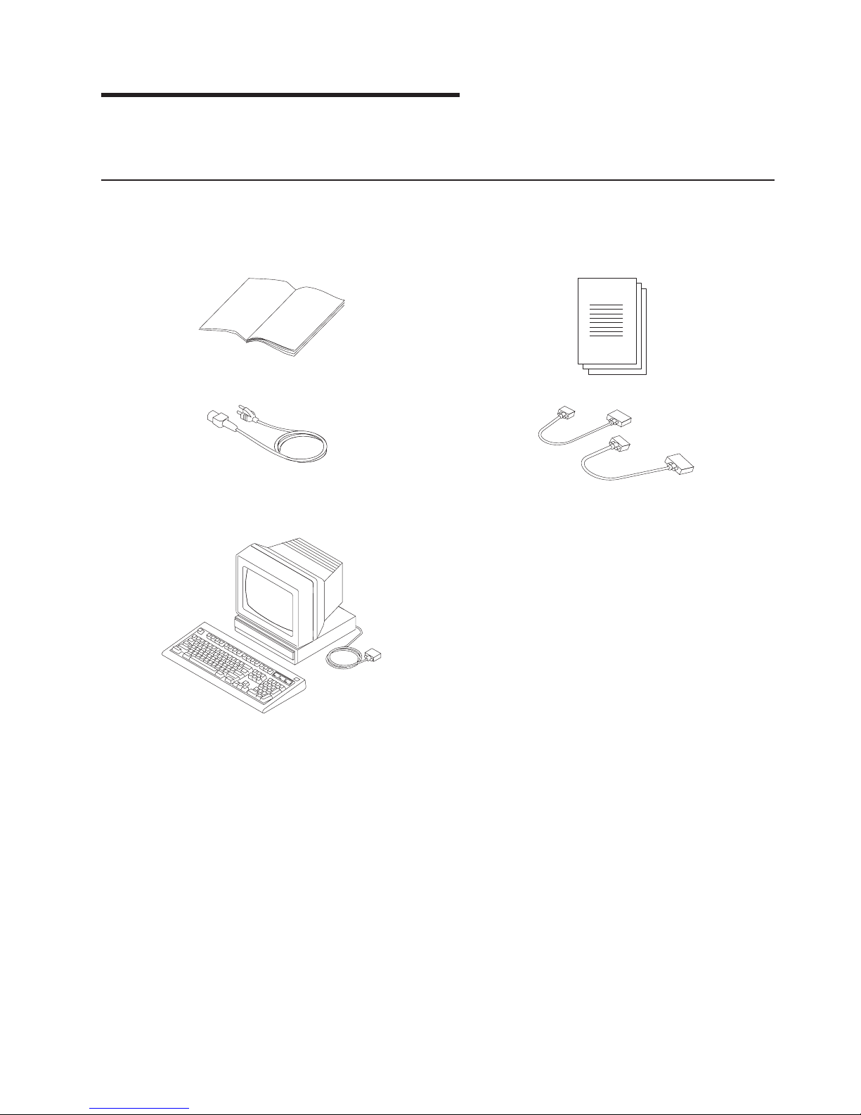
Step 1. Check Your Inventory ............................1
IntelliStation POWER 9114 Model 275 ........................1
Step 2. Need Help? ................................3
Step 3. Read the Safety Notices ...........................3
Step 4. Check the Power Source ...........................4
Step 5. Are All of the Internal Options Installed?......................4
Step 6. Position the System Unit and Display ......................4
Step 7. Adjust the Stability Feet............................5
Step 8. Check Your Display or Console Type .......................5
Step 9. Attach the Display Cable Toroid .........................6
Step 10. Connect the Graphics Display .........................7
Step 11. Connect the Keyboard and Mouse (When Using a Graphics Display) ..........8
Step 12. Connect the Serial Devices, Parallel Devices, and ASCII Terminal ...........9
Step 13. Connect the Adapter Cables .........................10
Step 14. Are You Using an Ethernet Connection?.....................11
Step 15. Connect the Power Cables to the System ....................12
Step 16. Install the Rear Acoustical Cover .......................13
Step 17. Install the Power-On Button Guard.......................13
Step 18. Connect the Power Cables to Electrical Outlets ..................14
Step 19. Your System Hardware is Now Set Up .....................14
Step 20. Start Your Model 275............................15
Step 21. Run System Verification...........................16
Step 22. Access the System Documentation ......................16
Hardware Documentation ............................16
Operating System Documentation .........................16
Chapter 2. Verifying the Hardware Operation .....................17
Considerations Before Running This Procedure .....................17
Power Procedures ...............................17
Loading the Online AIX Diagnostics on a System.....................18
Loading the Standalone Diagnostics on a System from CD-ROM ...............18
Running Standalone Diagnostics from a Network Installation Management (NIM) Server ......18
NIM Server Configuration ............................19
Client Configuration and Booting Standalone Diagnostics from the NIM Server .........19
Running System Verification ............................21
Performing Additional System Verification........................21
iii
Page 6

Stopping the Diagnostics..............................21
Verify that the Latest Firmware and Adapter Microcode are Installed..............22
Access the System Documentation ..........................22
Accessing Hardware Documentation ........................22
Accessing System Documentation .........................22
Chapter 3. Installing Options ...........................23
Handling Static-Sensitive Devices ..........................24
Options and Task List ...............................24
Stopping the System ...............................25
Starting the System................................25
Placing the Model 275 into the Service and Operating Position................26
Bezel Door ...................................26
Bezel Door Removal ..............................26
Bezel Door Replacement.............................26
Bezels ....................................27
Front Bezel Removal ..............................27
Front Bezel Replacement ............................27
Covers ....................................28
Service Access Cover Removal ..........................28
Service Access Cover Replacement.........................28
PCI Adapters ..................................29
Non-Hot-Pluggable PCI Adapter Removal ......................29
Adding or Replacing a Non-Hot-Pluggable PCI Adapter .................32
Hot-Swap System Fans ..............................34
Hot-Swap System Fan Removal ..........................34
Hot-Swap System Fan Replacement ........................34
Fan Tray Assembly ................................35
Removing the Fan Tray Assembly .........................35
Replacing the Fan Tray Assembly .........................37
Power Supply ..................................38
Power Supply Removal .............................38
Power Supply Replacement............................40
Installing a Power Supply ............................41
Media Drives (Diskette, CD-ROM, DVD-ROM, Tape, or Disk Drive) ..............42
Slimline Media ................................42
SCSI Media Devices ..............................43
Media Bay Chassis................................44
Removing the Media Bay Chassis .........................44
Replacing the Media Bay Chassis .........................44
Disk Drive Bezels and Fillers ............................45
Installing a Disk Drive Bezel to a Disk Drive......................45
Removing a Disk Drive Bezel from a Disk Drive or Filler .................46
Hot-Plug Disk Drives ...............................47
Deconfiguring (Removing) or Configuring a Disk Drive ..................47
Hot-Plug Disk Drive Removal ...........................49
Installing Hot-Plug Disk Drive ...........................51
Disk Drive Backplane ...............................52
Removing the Disk Drive Backplane ........................52
Installing or Replacing the Disk Drive Backplane ....................53
Memory DIMMs .................................54
Memory DIMM Installation and Replacement .....................54
Memory DIMM Removal .............................56
Service Processor Assembly ............................57
Removing the Service Processor Assembly ......................57
Replacing the Service Processor Assembly ......................57
iv IntelliStation POWER 9114 Model 275 Installation Guide
Page 7

Replacing the Battery ...............................59
Appendix A. Communications Statements ......................61
Federal Communications Commission (FCC) Statement ..................61
European Union (EU) Statement ...........................62
International Electrotechnical Commission (IEC) Statement .................62
United Kingdom Telecommunications Safety Requirements .................62
Avis de conformité aux normes du ministère des Communications du Canada ..........62
Canadian Department of Communications Compliance Statement ..............62
VCCI Statement .................................63
Radio Protection for Germany ............................63
Appendix B. Environmental Notices .........................65
Product Recycling and Disposal ...........................65
Environmental Design ...............................65
Acoustical Noise Emissions.............................65
Declared Acoustical Noise Emissions ........................65
Appendix C. Notices ...............................67
Appendix D. System Records ...........................69
Identification Numbers...............................69
Device Records .................................70
Memory Card .................................70
Options ...................................71
SCSI IDs and Bay Locations ...........................72
Appendix E. General Attributes Required When Using a TTY Terminal ...........73
Additional Communication Attributes .........................74
Additional Keyboard Attributes ............................74
Additional Printer Attributes .............................75
Appendix F. Firmware Updates ...........................77
Determining the Level of Firmware on the System ....................77
System Firmware Update Using a Locally Available Image .................77
Index .....................................79
Contents v
Page 8

vi IntelliStation POWER 9114 Model 275 Installation Guide
Page 9

Safety Notices
A danger notice indicates the presence of a hazard that has the potential of causing death or serious
personal injury. Danger notices appear on the following pages:
v vii
v 3
v 38
A caution notice indicates the presence of a hazard that has the potential of causing moderate or minor
personal injury. Caution notices appear on the following pages:
v vii
v ix
v 3
v 5
v 12
v 23
v 59
Note: For a translation of these notices, see System Unit Safety Information, order number SA23-2652.
Electrical Safety
Observe the following safety instructions any time you are connecting or disconnecting devices attached to
the workstation.
DANGER
An electrical outlet that is not correctly wired could place hazardous voltage on metal parts of
the system or the devices that attach to the system. It is the responsibility of the customer to
ensure that the outlet is correctly wired and grounded to prevent an electrical shock.
Before installing or removing signal cables, ensure that the power cables for the system unit
and all attached devices are unplugged.
When adding or removing any additional devices to or from the system, ensure that the power
cables for those devices are unplugged before the signal cables are connected. If possible,
disconnect all power cables from the existing system before you add a device.
Use one hand, when possible, to connect or disconnect signal cables to prevent a possible
shock from touching two surfaces with different electrical potentials.
During an electrical storm, do not connect cables for display stations, printers, telephones, or
station protectors for communications lines.
D05
CAUTION:
This product is equipped with a three-wire power cable and plug for the user’s safety. Use this
power cable with a properly grounded electrical outlet to avoid electrical shock.
C01
vii
Page 10

DANGER
To prevent electrical shock hazard, disconnect all power cables from the electrical outlet before
relocating the system.
D01
viii IntelliStation POWER 9114 Model 275 Installation Guide
Page 11

Laser Safety Information
CAUTION:
This product may contain a CD-ROM, DVD-ROM, or laser module on a PCI card, which are class 1
laser products.
C30
Laser Compliance
All lasers are certified in the U.S. to conform to the requirements of DHHS 21 CFR Subchapter J for class
1 laser products. Outside the U.S., they are certified to be in compliance with the IEC 825 (first edition
1984) as a class 1 laser product. Consult the label on each part for laser certification numbers and
approval information.
CAUTION:
All IBM laser modules are designed so that there is never any human access to laser radiation
above a class 1 level during normal operation, user maintenance, or prescribed service conditions.
Data processing environments can contain equipment transmitting on system links with laser
modules that operate at greater than class 1 power levels. For this reason, never look into the end
of an optical fiber cable or open receptacle. Only trained service personnel should perform the
inspection or repair of optical fiber cable assemblies and receptacles.
C25, C26
Safety Notices ix
Page 12

x IntelliStation POWER 9114 Model 275 Installation Guide
Page 13

Data Integrity and Verification
IBM computer systems contain mechanisms designed to reduce the possibility of undetected data corruption
or loss. This risk, however, cannot be eliminated. Users who experience unplanned outages, system failures,
power fluctuations or outages, or component failures must verify the accuracy of operations performed and
data saved or transmitted by the system at or near the time of the outage or failure. In addition, users must
establish procedures to ensure that there is independent data verification before relying on such data in
sensitive or critical operations. Users should periodically check the IBM support websites for updated
information and fixes applicable to the system and related software.
xi
Page 14

xii IntelliStation POWER 9114 Model 275 Installation Guide
Page 15

About This Book
This book provides information about the IntelliStation POWER 9114 Model 275, specifically how to set up
and cable the system, install and remove options, use the system diagnostics to verify the system
operation, and record your system configuration.
ISO 9000
ISO 9000 registered quality systems were used in the development and manufacturing of this product.
Highlighting
The following highlighting conventions are used in this book:
Bold Identifies commands, subroutines, keywords, files, structures, directories, and other items
whose names are predefined by the system. Also identifies graphical objects such as buttons,
labels, and icons that the user selects.
Italics Identifies parameters whose actual names or values are to be supplied by the user.
Monospace Identifies examples of specific data values, examples of text similar to what you might see
displayed, examples of portions of program code similar to what you might write as a
programmer, messages from the system, or information you should actually type.
Accessing Information
Documentation for the IBM Eserver pSeries is available online. Visit the IBM Eserver pSeries
Information Center at http://publib16.boulder.ibm.com/pseries/en_US/infocenter/base.
v To access the pSeries publications, click Hardware documentation.
v To view information about the accessibility features of Eserver pSeries hardware and the AIX operating
system, click AIX and pSeries accessibility.
References to AIX Operating System
This document may contain references to the AIX operating system. If you are using another operating
system, consult the appropriate documentation for that operating system.
This document may describe hardware features and functions. While the hardware supports them, the
realization of these features and functions depends upon support from the operating system. AIX provides
this support. If you are using another operating system, consult the appropriate documentation for that
operating system regarding support for those features and functions.
Related Publications
The following publications provide additional information about your system unit:
v The IntelliStation POWER 9114 Model 275 User’s Guide, order number SA38-0635, contains
information to help users use the system, use the service aids, and solve minor problems.
v The IntelliStation POWER 9114 Model 275 Service Guide, order number SA38-0636, contains reference
information, maintenance analysis procedures (MAPs), error codes, removal and replacement
procedures, and a parts catalog.
v The RS/6000 Eserver pSeries Diagnostic Information for Multiple Bus Systems, order number
SA38-0509, contains diagnostic information, service request numbers (SRNs), and failing function codes
(FFCs).
xiii
Page 16

v The RS/6000 Eserver pSeries Adapters, Devices, and Cable Information for Multiple Bus Systems,
order number SA38-0516, contains information about adapters, devices, and cables for your system.
This manual is intended to supplement the service information found in the RS/6000 Eserver pSeries
Diagnostic Information for Multiple Bus Systems.
v The Site and Hardware Planning Guide, order number SA38-0508, contains information to help you plan
your installation.
v The System Unit Safety Information, order number SA23-2652, contains translations of safety
information used throughout this book.
v The PCI Adapter Placement Reference, order number SA38-0538, contains information regarding slot
restrictions for adapters that can be used in this system.
Ergonomic Information
After you have set up your system, we encourage you to visit the Healthy Computing Web site. Good
ergonomic practice is important to get the most from your workstation and to avoid discomfort. This means
that the equipment and the workplace should be arranged to suit your individual needs and the kind of
work you do.
The Healthy Computing Web site gives ergonomic guidelines to help you understand the ergonomic
considerations that you should know when working at a computer workstation. The address is:
http://www.us.pc.ibm.com/healthycomputing
Trademarks
The following terms are trademarks of International Business Machines Corporation in the United States,
other countries, or both:
v AIX
v AIX 5L
v IBM
v pSeries
v Eserver
Other company, product, and service names may be trademarks or service marks of others.
xiv IntelliStation POWER 9114 Model 275 Installation Guide
Page 17
Chapter 1. Setting Up the System
To set up your system, follow the procedures in this chapter.
Step 1. Check Your Inventory
IntelliStation POWER 9114 Model 275
h Books, CD-ROM and Other Media h ″About Your Machine″ Document
h Power Cables (1 standard, 2 optional) h 9-Pin to 25-Pin Serial Converters (2) (optional)
h ASCII Terminal (optional)
1
Page 18
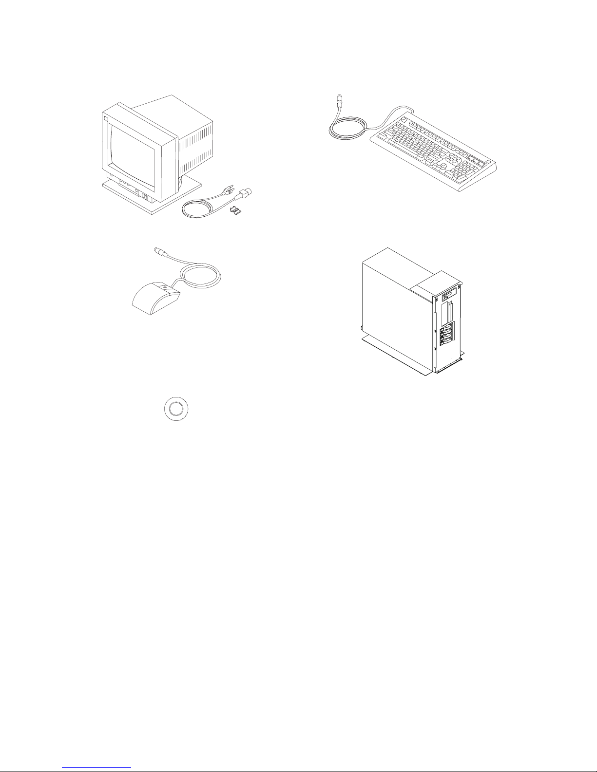
Inventory table continued from the previous page.
h Display, Cable (optional), and Cable Toroid (optional) h Keyboard (optional), Wrist/Palm Rest (optional)
h Mouse (optional) hModel 275
h Power-On Guard
2 IntelliStation POWER 9114 Model 275 Installation Guide
Page 19

Step 2. Need Help?
If you encounter difficulties while setting up your system unit, contact your sales representative for
assistance.
Step 3. Read the Safety Notices
Before continuing, read the following safety information. Do not plug any cables into the system unit,
adapters, or electrical outlets until you have reviewed this information. Make sure none of the power cords
are connected before continuing to the next step.
In the system you are about to set up:
v The ac power-interface connector is considered the main power disconnect device.
v This system has redundant power supply capabilities. Meaning your system has the capability of
running two power supplies simultaneously. When instructed to disconnect the power source, ensure
that all power cables have been unplugged.
DANGER
An electrical outlet that is not correctly wired could place hazardous voltage on metal parts of
the system or the devices that attach to the system. It is the responsibility of the customer to
ensure that the outlet is correctly wired and grounded to prevent an electrical shock.
Before installing or removing signal cables, ensure that the power cables for the system unit
and all attached devices are unplugged.
When adding or removing any additional devices to or from the system, ensure that the power
cables for those devices are unplugged before the signal cables are connected. If possible,
disconnect all power cables from the existing system before you add a device.
Use one hand, when possible, to connect or disconnect signal cables to prevent a possible
shock from touching two surfaces with different electrical potentials.
During an electrical storm, do not connect cables for display stations, printers, telephones, or
station protectors for communications lines.
D05
CAUTION:
This product is equipped with a three-wire power cable and plug for the user’s safety. Use this
power cable with a properly grounded electrical outlet to avoid electrical shock.
C01
DANGER
To prevent electrical shock hazard, disconnect all power cables from the electrical outlet before
relocating the system.
D01
Chapter 1. Setting Up the System 3
Page 20

Step 4. Check the Power Source
This system can be equipped with two power supplies. When two power supplies are installed, the power
source to the system unit should be provided on two separate power circuits. If the power is supplied this
way, when there is an interruption on one circuit, the system will keep running on the other circuit.
Step 5. Are All of the Internal Options Installed?
These instructions are for systems that have internal options (such as adapters, disk drives, or memory
upgrades) already installed.
If you have internal options that are not installed, install them now. Refer to Chapter 3, “Installing Options”,
on page 23, and then return here.
Step 6. Position the System Unit and Display
Position the system unit and display (optional) at or near their installed location.
Observe the following guidelines when you are positioning the system unit:
v The system unit weighs between 34 kg (75 pounds) and 41 kg (90 pounds). Do not try to lift the system
unit by yourself.
v Displays and ASCII terminals can weigh as much as 35 kg (77 pounds). Use caution when lifting or
moving the display or ASCII terminal.
v Leave enough space around the system unit to safely and easily complete the setup procedures.
v Observe standard ergonomic guidelines while arranging your system unit so that you can work
comfortably and safely. For more information on arranging your workstation, visit the Healthy Computing
Web address at: http://www.pc.ibm.com/us/healthycomputing.
v Be sure to maintain at least 51 mm (2 inches) of space on the sides of the system unit and 152 mm (6
inches) at the rear of the system unit to allow the system unit to cool properly. The front of the system
requires a minimum of 76 mm (3 inches) of space. Blocking the air vents can cause overheating, which
might result in a malfunction or permanent damage to the system unit.
v Place the system unit in a location where it can safely and easily reach any necessary power outlets
and network connections.
v Place the display or ASCII terminal in a stable and sturdy location.
4 IntelliStation POWER 9114 Model 275 Installation Guide
Page 21
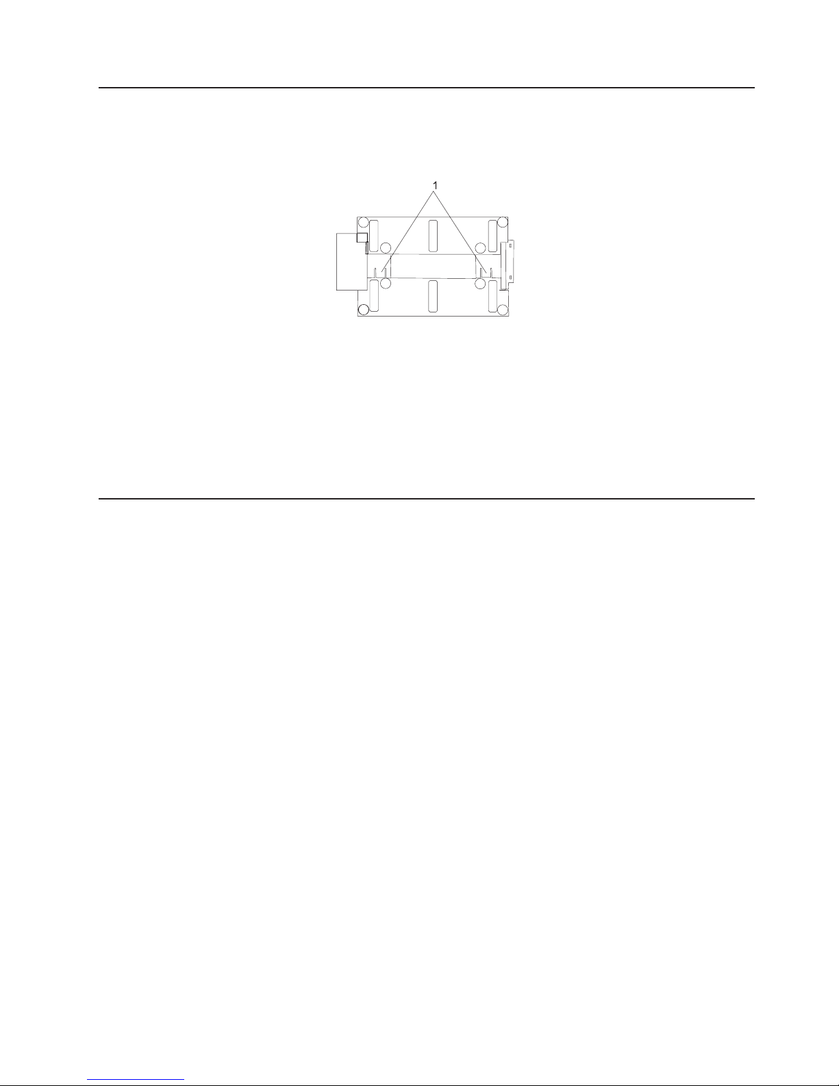
Step 7. Adjust the Stability Feet
To retract the stability feet, push the tabs down and slide the plates inward. To extend the feet, slide the
plates outward until the retraction tabs are fully visible and snap securely into place.
1 Stability Feet Retraction Tabs (bottom view)
CAUTION:
The system is equipped with stability feet to help ensure that the system unit cannot easily be
tipped over. The stability feet might be either standard non-adjustable feet or an adjustable base
stability foot. Ensure that the stability feet are installed and adjusted to their fully extended
position.
C34
Step 8. Check Your Display or Console Type
Notes:
1. If you are using an ASCII terminal with a keyboard as the console for this system, and do not have a
graphics display to connect, refer to “Step 12. Connect the Serial Devices, Parallel Devices, and ASCII
Terminal” on page 9.
2. If you are using a graphics display with a keyboard and mouse, continue with “Step 9. Attach the
Display Cable Toroid” on page 6.
If you ordered a graphics display with your system unit, the graphics adapter has been set to use the
highest display resolution and refresh rate available for that display. If you want to:
v Attach another display to your system unit
OR
v Change the default display resolution or refresh rate
after completing the installation steps, refer to the Customer Installable Options Library CD-ROM for the
documentation for your graphics adapter.
As shown in “Step 9. Attach the Display Cable Toroid” on page 6, connect the graphics display cable to the
back of the display and to the graphics adapter connector. Consult the ″About Your Machine″ document for
the locations of installed adapters.
For more information about your display, refer to the documentation included with the display.
Chapter 1. Setting Up the System 5
Page 22
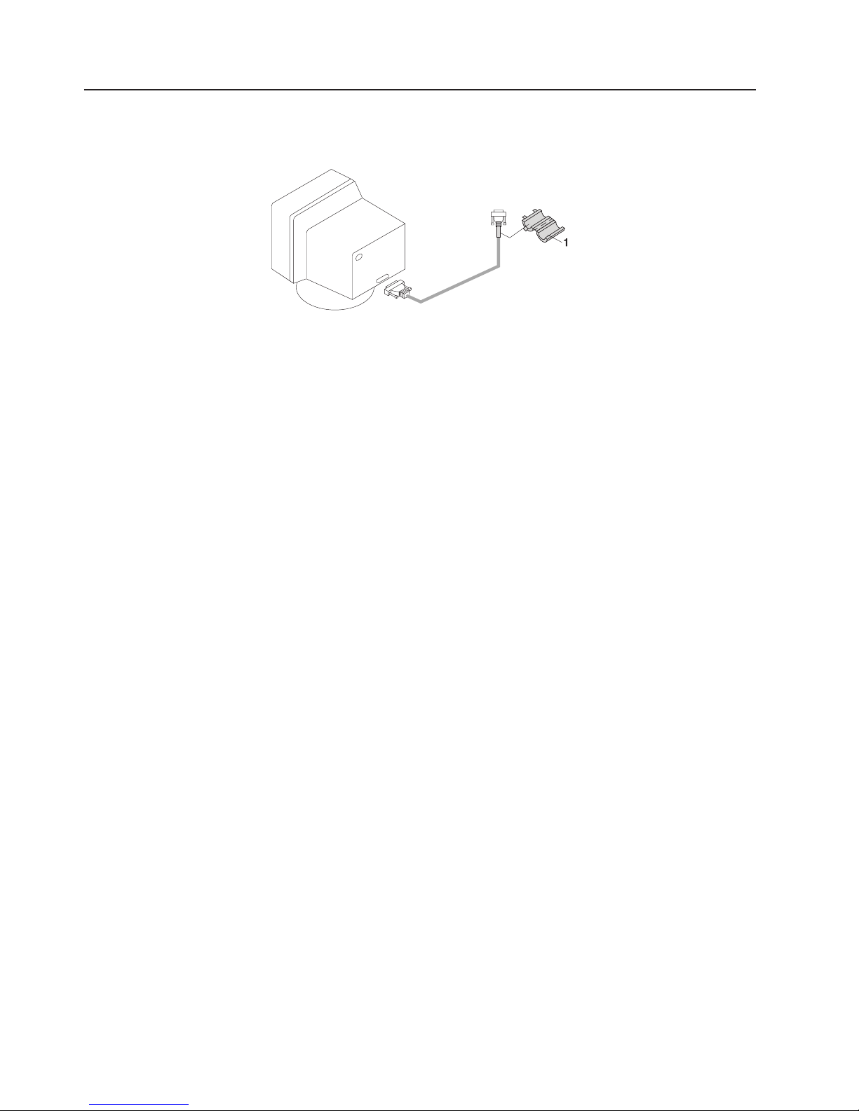
Step 9. Attach the Display Cable Toroid
If the cable for your display does not include a toroid, locate the toroid shipped with your system and
follow the installation instructions included with the toroid.
1 Display Cable Toroid
6 IntelliStation POWER 9114 Model 275 Installation Guide
Page 23
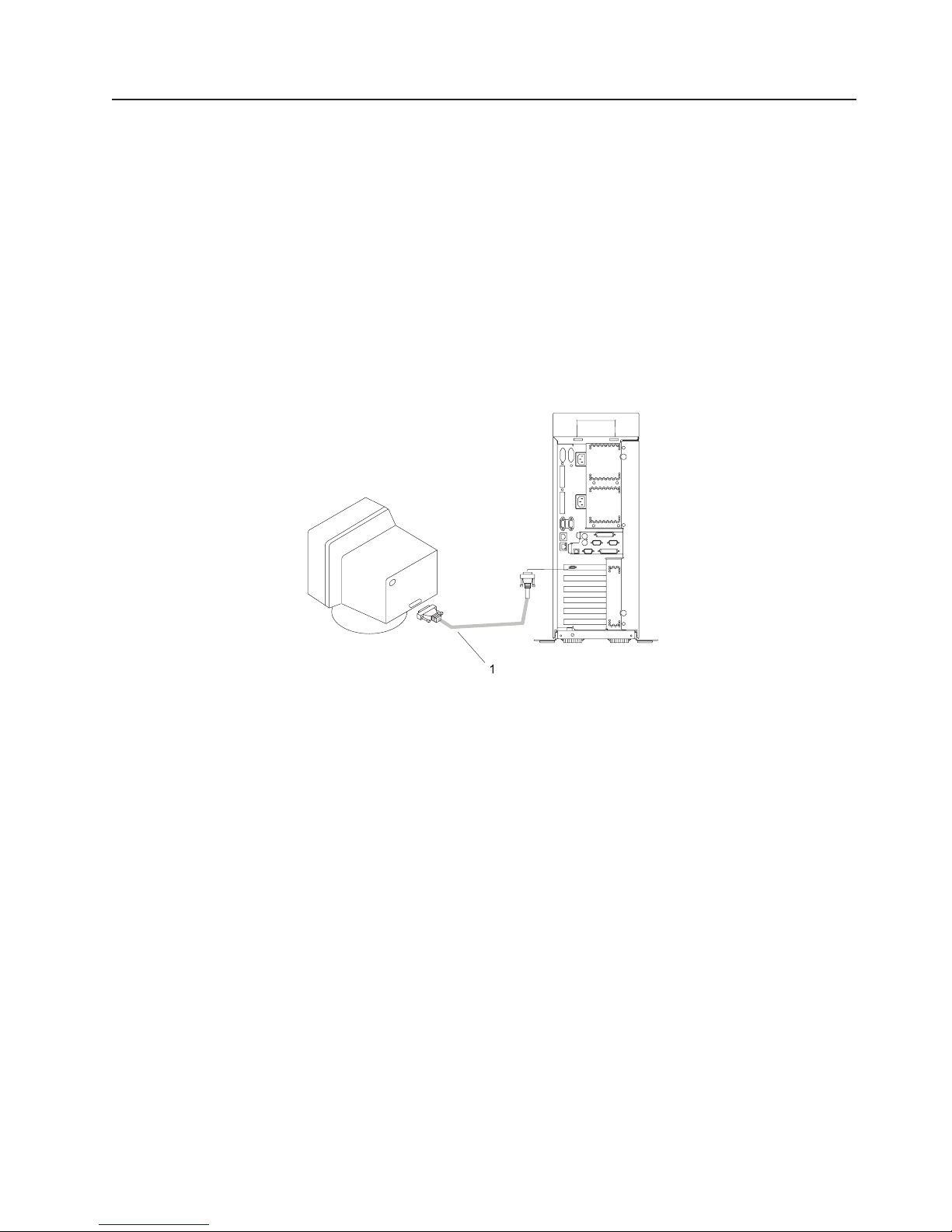
Step 10. Connect the Graphics Display
Note: If you are using an ASCII terminal as the console for this system, and do not have a graphics
display to connect, continue with “Step 12. Connect the Serial Devices, Parallel Devices, and ASCII
Terminal” on page 9.
As shown in “Step 9. Attach the Display Cable Toroid” on page 6, connect the graphics display cable to the
back of the display and to the graphics adapter connector. For the locations of installed adapters, consult
the ″About Your Machine″ document.
For more information about your display, refer to the documentation included with the display.
Notes:
1. A PCI 2D graphics adapter or 3D graphics adapter can be installed in any of the six PCI slots.
2. Some displays require an additional cable.
1 Display Cable
Chapter 1. Setting Up the System 7
Page 24
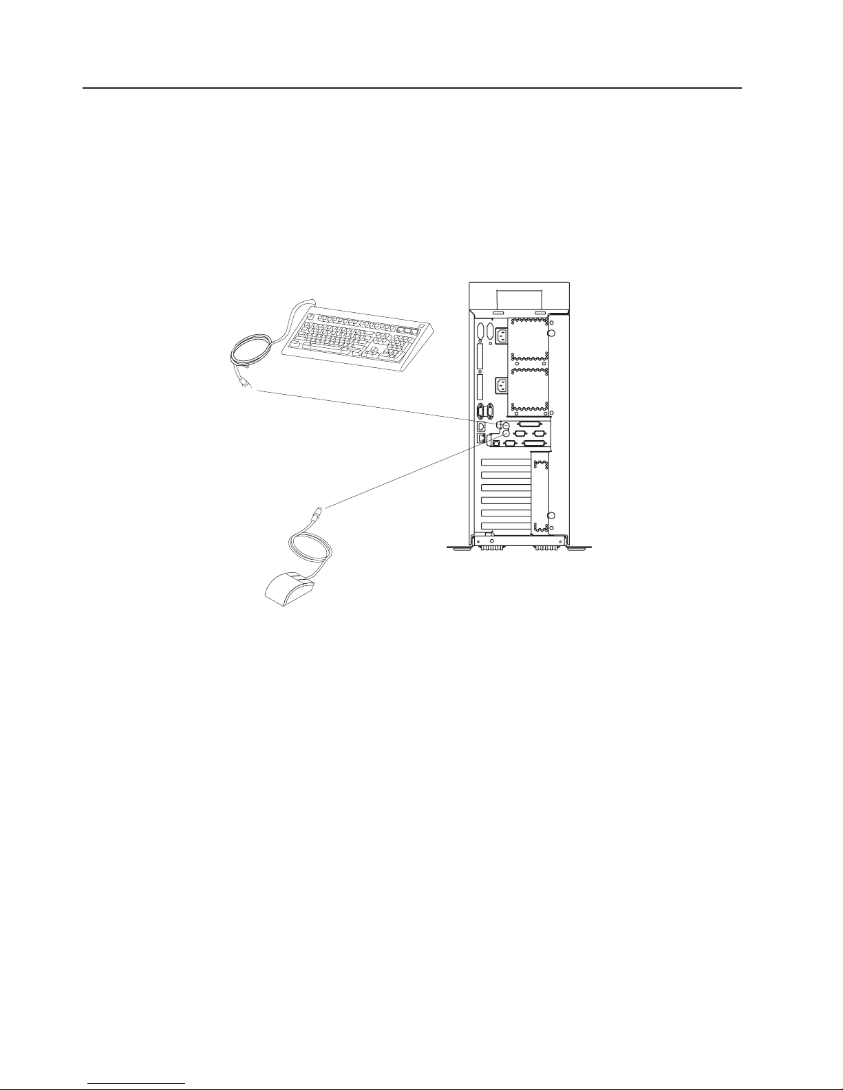
Step 11. Connect the Keyboard and Mouse (When Using a Graphics
Display)
Note: Before doing this step, read and understand “Step 3. Read the Safety Notices” on page 3.
If a wrist or palm rest was included with your keyboard and you want to attach it, refer to the keyboard
documentation for installation instructions.
As shown in the following illustration, connect the keyboard and mouse to the connectors on the rear of
the system unit.
8 IntelliStation POWER 9114 Model 275 Installation Guide
Page 25
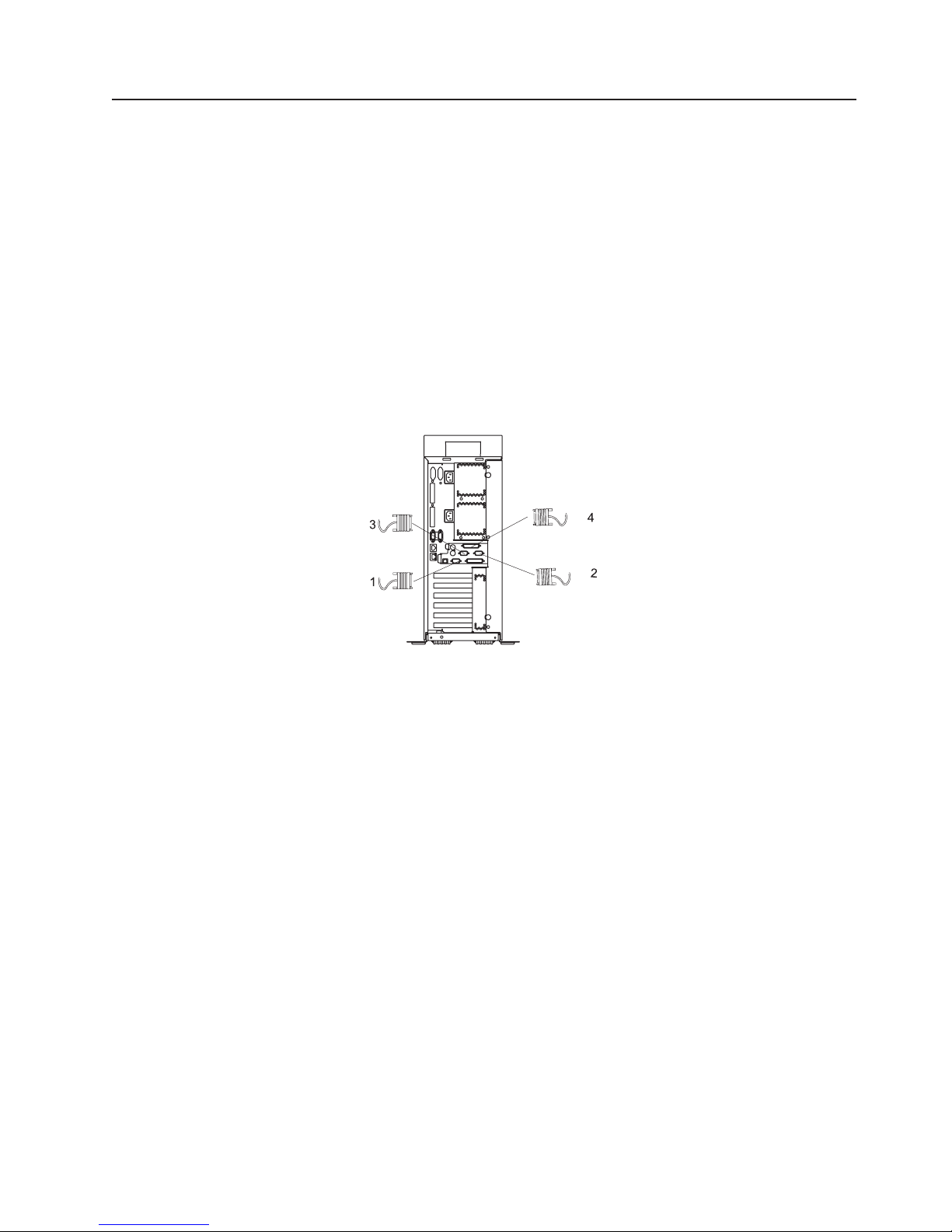
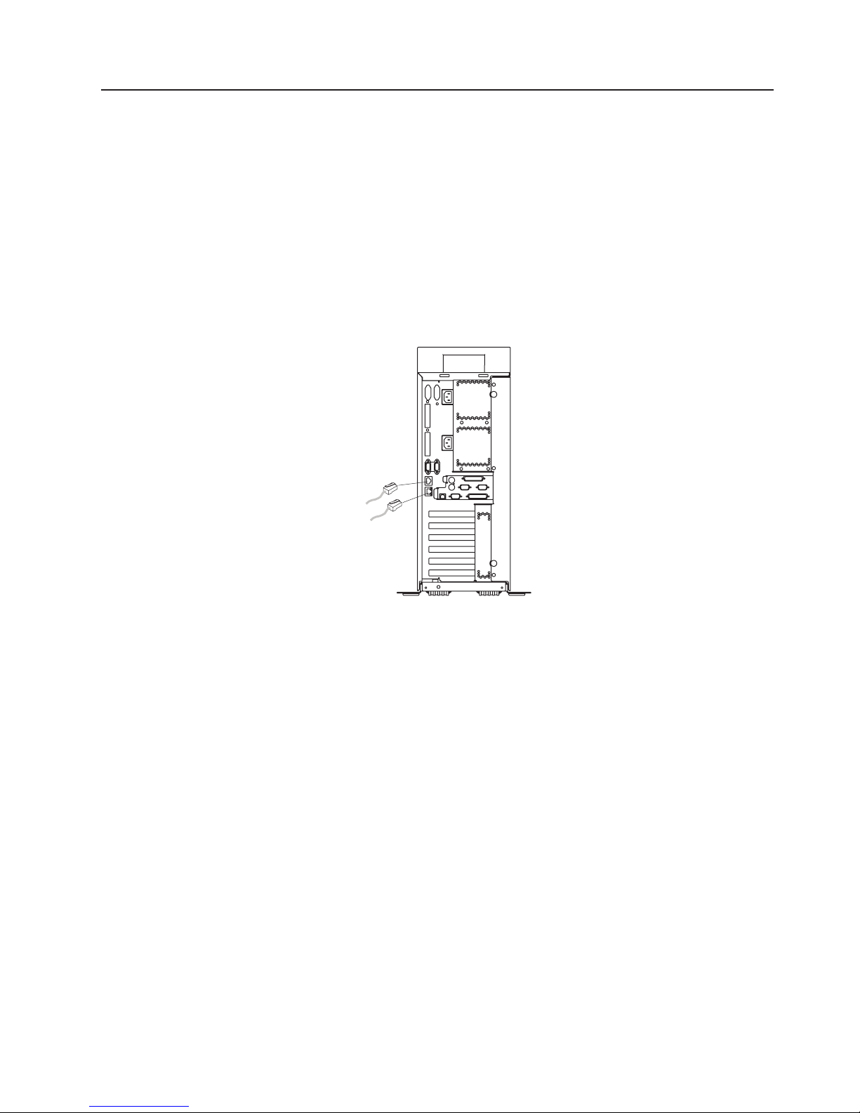
Step 12. Connect the Serial Devices, Parallel Devices, and ASCII
Terminal
Notes:
1. Before doing this step, read and understand “Step 3. Read the Safety Notices” on page 3.
2. To connect a local ASCII terminal, connect the terminal to the rear serial port by using the 9-pin to
25-pin serial converter cable. The 9-pin to 25-pin serial converter is a customer-purchased option.
3. If you have a remote ASCII terminal, connect it through an external modem to serial connector S1, and
connect a local ASCII terminal to serial connector S2 or serial connector S3.
If you have a local ASCII terminal or a single serial device, connect it to serial connector S1.
You can connect additional serial devices to the two remaining serial ports (S2 and S3) that are located at
the rear of the system.
If you have a parallel device (such as a printer), connect it to the parallel connector.
1 Serial Port 1 Connector
2 Serial Port 2 Connector
3 Serial Port 3 Connector
4 Parallel Connector
Chapter 1. Setting Up the System 9
Page 26
The current usage for the serial port connectors is as follows:
Serial Port Number Location Examples of Applicable Usage
Serial Port 1 (S1
Rear)
Serial Port 2 (S2) Rear of the System Service Processor menus, HACMP, ASCII Terminal for AIX Console,
Serial Port 3 (S3) Rear of the System HACMP, UPS (uninterruptible power supply), ASCII Terminal for AIX
Rear of the System Service Processor menus, Service Agent, PDA system management
applications (interface cable required), ASCII Terminal for AIX
Console, and Modems
and Modems
Console, and Modems
Note: Serial port S1 is never used to run HACMP or to attach a UPS. If you are configuring your system
to run HACMP with a UPS attached, you must connect the HACMP cable to serial port S2 and the
UPS cable to serial port S3. Do not run a UPS connected to serial port S2. If you decide to
disconnect HACMP, you must reset the service processor using the pinhole reset switch before
running another application. The service processor pinhole reset switch is located on the operator
panel.
Step 13. Connect the Adapter Cables
Note: Before doing this step, read and understand “Step 3. Read the Safety Notices” on page 3.
If you are using any optional adapters (such as token ring or 8-port EIA-232), connect the cables to the
appropriate adapter connectors in the PCI slots of your machine. For the locations of installed adapters,
consult the ″About Your Machine″ document.
10 IntelliStation POWER 9114 Model 275 Installation Guide
Page 27
Step 14. Are You Using an Ethernet Connection?
If you are unsure whether you are using an Ethernet connection, ask your system administrator. If you are
not using Ethernet or you have already connected your Ethernet to an adapter, continue to “Step 15.
Connect the Power Cables to the System” on page 12.
To connect the Ethernet cable, do the following:
Note: The twisted-pair connector is compatible with the IEEE 802.3 Ethernet network 10/100/1000 Base T
link.
1. Connect the twisted-pair cable to one of two RJ-45 connectors located on the rear of the system
drawer. For RJ-45 connector locations, see the following illustration.
2. The twisted-pair Ethernet cable is now installed. Continue with “Step 15. Connect the Power Cables to
the System” on page 12.
Chapter 1. Setting Up the System 11
Page 28
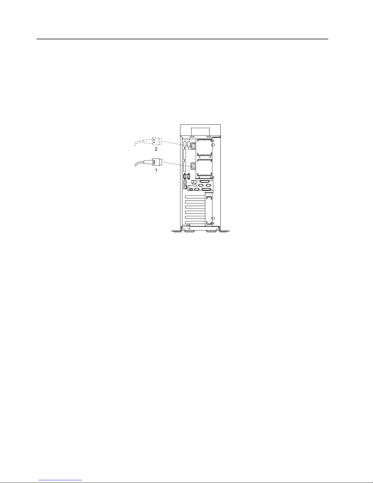
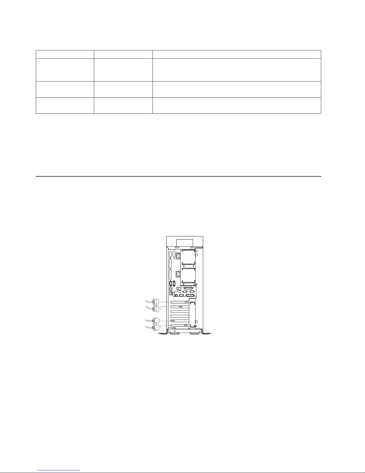
Step 15. Connect the Power Cables to the System
Plug the power cables into the system, display, and attached devices.
Notes:
1. The system could be equipped with two power supplies. Each power supply needs its own power
cable.
2. If your system is equipped with one power supply, connect the power cable to the power receptacle. A
second power receptacle is present when a second (redundant) power supply has been added to the
system drawer. See the following illustration.
1 Primary Power Supply Cable
2 Redundant Power Supply Cable
CAUTION:
This product is equipped with a three-wire power cable and plug for the user’s safety. Use this
power cable with a properly grounded electrical outlet to avoid electrical shock.
C01
12 IntelliStation POWER 9114 Model 275 Installation Guide
Page 29
Step 16. Install the Rear Acoustical Cover
Install the acoustical cover to the rear of the system.
Note: It is important to have the rear acoustical cover installed to suppress excess noise from your
system.
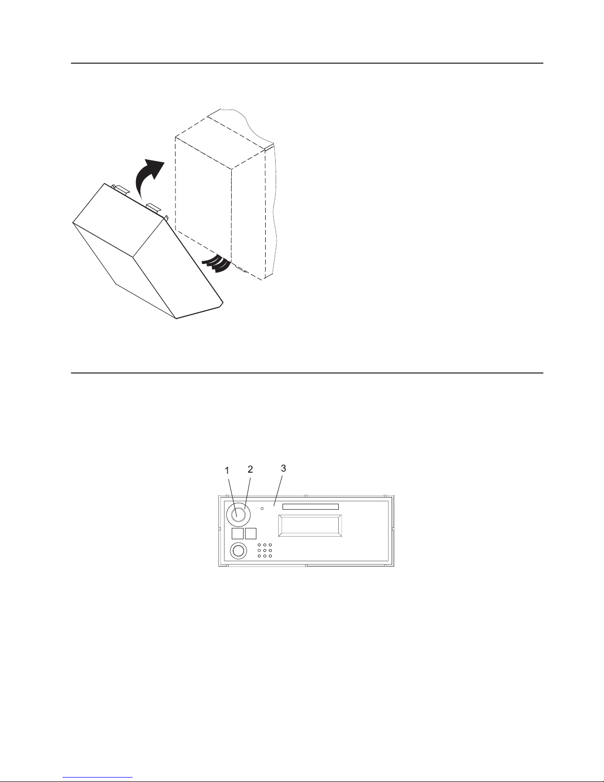
Step 17. Install the Power-On Button Guard
To help prevent accidental power-on or power-off operations, ensure that the power-on button guard is
installed.
Snap the power-on button guard into place securely around the power-on button located on the operator
panel. See the following illustration.
1 Power-On Button
2 Power-On Button Guard
3 Operator Panel
Chapter 1. Setting Up the System 13
Page 30
Step 18. Connect the Power Cables to Electrical Outlets
Connect the power source to the system unit.
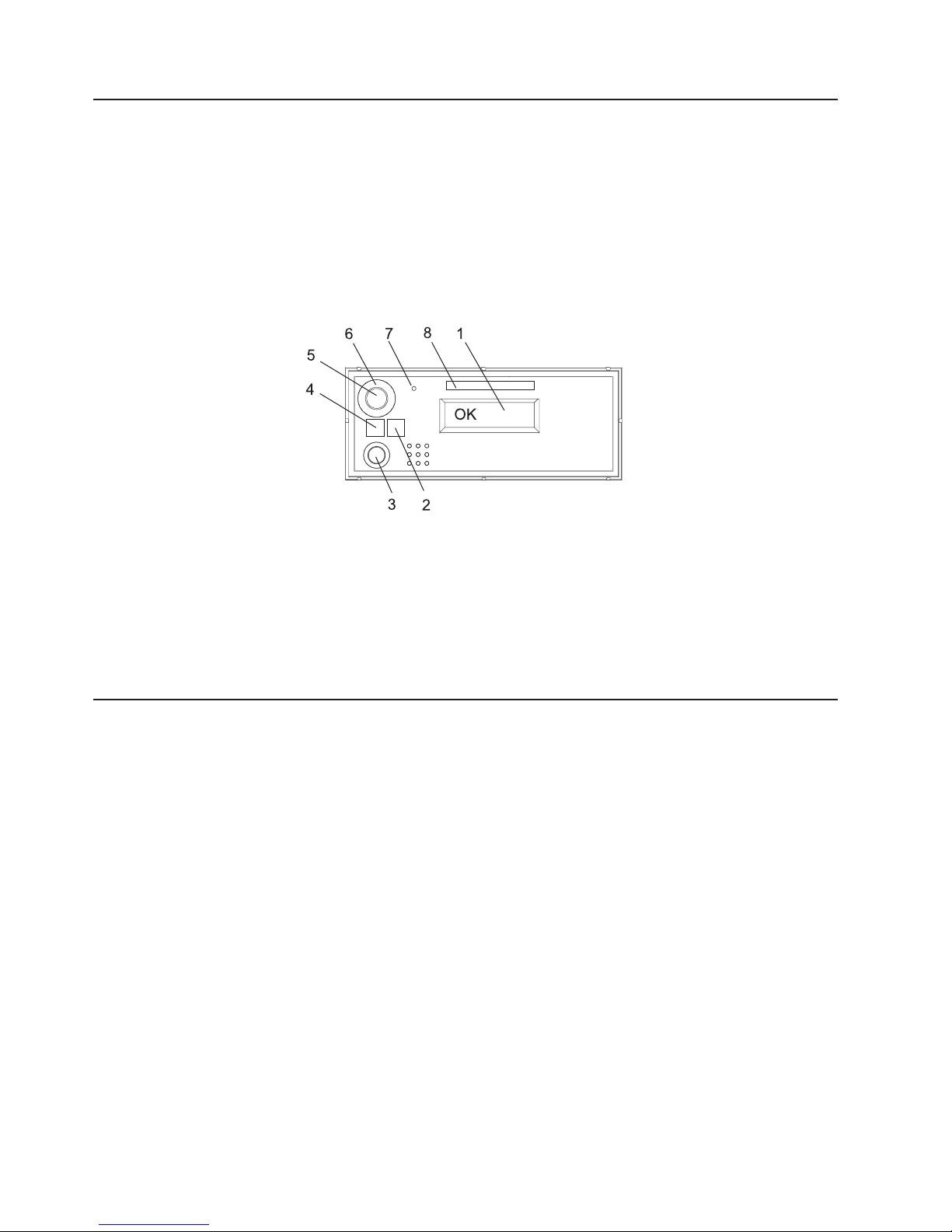
After 10 to 20 seconds, the system comes up to standby mode. The indicators of standby mode are as
follows:
v The power LED is slowly blinking.
v OK is visible in the operator panel display.
The following illustration shows the operator panel in standby mode with OK visible in the operator panel
display.
1 Operator Panel Display 5 Power-On Button
2 Attention LED 6 Power-On Button Guard
3 System Reset Button 7 Service Processor Reset Switch (Pinhole)
4 Power LED 8 Serial Number Label
If your system does not come up to standby mode, check all cables for good connection. If you cannot find
a problem, call your support center for assistance.
Step 19. Your System Hardware is Now Set Up
Arrange your system unit and attached devices so that you can use them comfortably.
If an operating system has been preinstalled in your system, continue to “Step 20. Start Your Model 275”
on page 15.
If you plan to install the operating system now, see the installation instructions provided with your
operating system.
Installation of the operating system can be accomplished in one of the following ways:
v Installed from a CD (if a CD-ROM drive is installed). On the IntelliStation POWER 9114 Model 275, the
CD-ROM drive is a customer-installable option.
v If you are installing the AIX operating system, AIX can be installed from a Network Installation
Management (NIM) server. For information about installing AIX from a NIM server, see the AIX 5L
Installation Guide and Reference, order number SC23-4389. For other software installation, refer to the
documentation provided with the software.
14 IntelliStation POWER 9114 Model 275 Installation Guide
Page 31

Step 20. Start Your Model 275
To power on the system, do the following:
1. Open the bezel door.
2. Before you press the power button on your operator panel, observe the following:
v The power LED is slowly blinking.
v An OK prompt is visible in the operator panel display.
1 Operator Panel Display 5 Power LED
2 Front Serial Connector (FS1) 6 Power-On Button
3 Attention LED 7 Power-On Guard
4 System Reset Button 8 Service Processor Reset Switch (Pinhole)
9 Serial Number Label
3. Press the power-on button on the operator panel.
After you press the power-on button located on the operator panel, observe the following:
a. The power LED begins to blink visibly faster.
b. The system cooling fans are activated after a short interval and can be heard accelerating to
operating speed.
Note: There is approximately a 30-second transition period between the time the power-on button
is pressed and the power LED remains on solid (no longer blinking).
c. The power LED stays on solid. Progress indicators, also referred to as checkpoints, are visible on
the operator panel display.
Chapter 1. Setting Up the System 15
Page 32

Step 21. Run System Verification
1. If your system displays the login prompt and you want to test your hardware, go to Chapter 2,
“Verifying the Hardware Operation”, on page 17.
2. If the login prompt does not display, recheck your installation procedures and try starting your system
again.
3. If your system continues to fail, call your service representative.
Step 22. Access the System Documentation
If you are installing this system and another person is the system administrator, deliver this book to the
system administrator when the installation is complete. Ensure that the system administrator reads the
following information and is aware of the options to access the documentation for the new system.
Hardware Documentation
IBM Eserver pSeries hardware publications are available online. To access the online hardware books,
visit our IBM Eserver pSeries Information Center at
http://publib16.boulder.ibm.com/pseries/en_US/infocenter/base. Click Hardware Documentation.
Operating System Documentation
Documentation for the AIX operating system is available from the IBM Eserver pSeries Information
Center at http://publib16.boulder.ibm.com/pseries/en_US/infocenter/base. Select AIX documentation. The
AIX Documentation CD contains the base set of publications for the operating system, including
system-management and end-user documentation.
16 IntelliStation POWER 9114 Model 275 Installation Guide
Page 33

Chapter 2. Verifying the Hardware Operation
The system verification procedure checks the system for correct hardware operation. If you have a
problem with your system in the future, use this procedure to test the system hardware to help you
determine if you have a hardware problem. Run the system verification procedure as described in the
following steps.
Considerations Before Running This Procedure
These verification procedures use either online AIX diagnostics or standalone AIX diagnostics. Either the
online AIX diagnostics or the standalone AIX diagnostics must be available to perform this procedure.
Read the following before using this procedure:
v If this system unit is directly attached to another system unit or attached to a network, be sure
communications with the other systems are stopped.
v This procedure requires use of all of the system resources. No other activity can be running on the
system while you are performing this procedure.
v This procedure requires a display attached to a graphics adapter, or an ASCII terminal attached to the
S1 or S2 port.
Does the system have online AIX diagnostics preinstalled?
YES Go to “Loading the Online AIX Diagnostics on a System” on page 18.
NO Go to “Loading the Standalone Diagnostics on a System from CD-ROM” on page 18.
Power Procedures
These power procedures are here for reference during the system verification tests. Do not perform any
power procedures until the verification procedures instruct you to do so.
Operator Panel Power-On Method
Perform the following steps to power on the system unit using the power button on the operator panel.
1. Look for OK on the operator panel display, which indicates that the system is in standby.
2. Press the power-on button on the operator panel.
The power LED on the operator panel starts blinking at a fast rate. 9xxx checkpoints appear in the
operator panel display.
When the power-on sequence is complete, the following events have occurred:
v The power LED on the system operator panel stops blinking and stays on.
v The power LEDs on the I/O subsystem come on and stay on.
17
Page 34

Loading the Online AIX Diagnostics on a System
To run the online diagnostics in service mode from the boot hard disk, do the following:
1. Stop all programs including the operating system (get help if needed).
2. Remove all tapes, diskettes, and CD-ROM discs.
3. Turn off the system unit power.
4. Turn on the system unit power.
5. After the keyboard POST indicator displays on the firmware console and before the last POST
indicator (speaker) displays, press the numeric 6 key on either the directly attached keyboard or the
ASCII terminal to indicate that a service mode boot should be initiated using the customized service
mode boot list.
6. Enter any requested password.
Note: If you are unable to load the diagnostics to the point when the DIAGNOSTIC OPERATING
INSTRUCTIONS display, call your support center for assistance.
Loading the Standalone Diagnostics on a System from CD-ROM
To run the standalone diagnostics in service mode from the CD-ROM, do the following:
Note: Online diagnostics are not available when the operating system is Linux.
1. Stop all programs including the operating system (get help if needed).
2. Remove all tapes, diskettes, and CD-ROM discs.
3. Turn off the system unit power.
4. Turn on the system unit power and immediately insert the diagnostic CD-ROM into the CD-ROM drive.
5. After the keyboard POST indicator displays on the firmware console and before the last POST
indicator (speaker) displays, press the numeric 5 key on either the directly attached keyboard or the
ASCII terminal to indicate that a service mode boot should be initiated using the default service mode
boot list.
6. Enter any requested password.
Note: If you are unable to load the diagnostics to the point when the DIAGNOSTIC OPERATING
INSTRUCTIONS display, call your support center for assistance.
Running Standalone Diagnostics from a Network Installation
Management (NIM) Server
A client system connected to a network with a Network Installation Management (NIM) server can boot
standalone diagnostics from the NIM server if the client-specific settings on both the NIM server and client
are correct.
Notes:
1. All operations to configure the NIM server require root user authority.
2. If you replace the network adapter in the client, the network-adapter hardware-address settings for the
client must be updated on the NIM server.
3. The Cstate for each standalone diagnostics client on the NIM server should be kept in the diagnostic
boot has been enabled state.
4. On the client system, the NIM server network adapter should be put in the bootlist after the boot disk
drive. This allows the system to boot in standalone diagnostics from the NIM server if there is a
problem booting from the disk drive. For information about setting the bootlist, see the Multiboot
section under “SMS” in the client system’s service guide.
18 IntelliStation POWER 9114 Model 275 Installation Guide
Page 35

NIM Server Configuration
Refer to the “Advanced NIM Configuration Tasks” chapter of the AIX 5L Installation Guide and Reference,
order number SC23-4389, for information about doing the following:
v Registering a client on the NIM server
v Enabling a client to run diagnostics from the NIM server
Documentation for the AIX operating system is available from the IBM Eserver pSeries Information
Center at http://publib16.boulder.ibm.com/pseries/en_US/infocenter/base. Select AIX documentation. The
AIX Documentation CD contains the base set of publications for the operating system, including
system-management and end-user documentation.
To verify that the client system is registered on the NIM server and the diagnostic boot is enabled, run the
lsnim -a Cstate -Z ClientName command from the command line on the NIM server. Refer to the
following table for system responses.
Note: The ClientName is the name of the system on which you want to run standalone diagnostics.
System Response Client Status
#name:Cstate:
ClientName:diagnostic boot has been
enabled:
#name:Cstate:
ClientName:ready for a NIM operation:
or
#name:Cstate:
ClientName:BOS installation has been
enabled:
0042-053 lsnim: there is no NIM object
named "ClientName"
The client system is registered on the NIM server and
enabled to run diagnostics from the NIM server.
The client is registered on the NIM server but not enabled
to run diagnostics from the NIM server.
Note: If the client system is registered on the NIM server
but Cstate has not been set, no data will be returned.
The client is not registered on the NIM server.
Client Configuration and Booting Standalone Diagnostics from the NIM
Server
To run standalone diagnostics on a client from the NIM server, do the following:
1. Remove any removable media (tape or CD-ROM disc).
2. Stop all programs including the operating system (get help if needed).
3. If you are running standalone diagnostics in a full system partition, verify with the system administrator
and system users that the system unit can shut down. Stop all programs, including the operating
system. Refer to the operating system documentation for shutdown command information.
In a partitioned system, make the CD-ROM drive available to the partition used to run standalone
diagnostics (refer to the IBM Hardware Management Console for pSeries Installation and Operations
Guide for more information). Verify with the system administrator and system users using that partition
that all applications on that partition must be stopped, and that the partition will be rebooted. Stop all
programs on that partition, including the operating system.
4. If you are in a full system partition, power on the system unit to run standalone diagnostics. In a
partitioned system, reboot the partition to run standalone diagnostics.
5. When the keyboard indicator is displayed (the word keyboard), press the number 1 key on the
keyboard to display the SMS menu.
6. Enter any requested passwords.
7. Select Setup Remote IPL (Initial Program Load).
Chapter 2. Verifying the Hardware Operation 19
Page 36

8. Enter the client address, server address, gateway address (if applicable), and subnet mask. Exit to the
Network Parameters screen.
9. If the NIM server is set up to allow pinging from the client system, use the ping utility in the RIPL utility
to verify that the client system can ping the NIM server. Under the ping utility, choose the network
adapter that provides the attachment to the NIM server to do the ping operation. If the ping returns
with an OK prompt, the client is prepared to boot from the NIM server. If ping returns with a FAILED
prompt, the client cannot proceed with the NIM boot.
If the ping fails, contact your service representative.
To do a one-time boot of the network adapter attached to the NIM server network, do the following:
1. Exit to the SMS Main screen.
2. Select Select Boot Options.
3. Select Install or Boot a Device.
4. On the Select Device Type screen, select Network.
5. Set the network parameters for the adapter from which you want to boot.
6. Exit completely from SMS. The system starts loading packets while doing a bootp from the network.
Follow the instructions on the screen to select the system console.
v If Diagnostics Operating Instructions Version x.x.x displays, standalone diagnostics have loaded
successfully.
v If the operating system login prompt displays, standalone diagnostics did not load. Check the following
items:
– The network parameters on the client may be incorrect.
– Cstate on the NIM server may be incorrect.
– Network problems might be preventing you from connecting to the NIM server.
Verify the settings and the status of the network. If you continue to have problems, contact your service
representative.
20 IntelliStation POWER 9114 Model 275 Installation Guide
Page 37

Running System Verification
When the Diagnostic Operating Instructions display, do the following to run system verification:
1. Press Enter.
2. If the terminal type is requested, you must use the Initialize Terminal option on the Function Selection
menu to initialize the operating system before you can continue with the diagnostics.
Note: If you use a virtual terminal on the HMC and you are asked to define the terminal type, the
virtual terminal is considered a VT320.
3. Select the System Verification option on the Diagnostic Mode Selection menu.
4. To run a general checkout of all installed resources, select the All Resource option on the Diagnostic
Selection menu. Follow the instructions on the screen to complete the checkout procedure.
To check one particular resource, select that resource on the Diagnostic Selection menu.
The checkout program ends with either of the following results:
v The Testing Complete screen displays a message stating No trouble was found.
v The A Problem Was Detected On (Time Stamp) menu displays, with either a service request number
(SRN) or an error code. Make a note of any codes displayed on the display or operator panel.
To perform additional system verification, go to “Performing Additional System Verification”. To exit
diagnostics, go to “Stopping the Diagnostics”.
Performing Additional System Verification
To perform additional system verification, do the following:
1. Press Enter to return to the Diagnostic Selection menu.
2. To check other resources, select the resource. When you have checked all of the resources you need
to check, go to “Stopping the Diagnostics”.
Stopping the Diagnostics
To stop the diagnostics, do the following:
1. To exit the diagnostics, press the F3 key (from a defined terminal) or press 99 (from an undefined
terminal).
2. If you changed any attributes on your terminal to run the diagnostics, change the settings back to
normal.
3. This completes the system verification.
If the server passed all the diagnostic tests, the verification process is complete and your server is ready
to use.
Chapter 2. Verifying the Hardware Operation 21
Page 38

Verify that the Latest Firmware and Adapter Microcode are Installed
Use the procedures in this section to verify that the latest firmware and adapter microcode are installed on
the system. The firmware and microcode are available from either of the following sources:
v Web site:
http://techsupport.services.ibm.com/server/mdownload2/download.html
From the Web site, follow the instructions for checking your system’s firmware level and for
downloading the latest level of code. Adapter and drive microcode packages are also available from this
Web site.
v Current Object Repository (CORE):
If you have access to CORE, do the following to access the firmware and microcode:
1. Access Current Object Repository (CORE).
2. Select CORE Product Family and eServer pSeries - RS/6000
3. Select CORE Machine Type and pSeries - RS/6000 - Microcode-System/Service
Access the System Documentation
If you are installing this system and another person is the system administrator, deliver this book to the
system administrator when the installation is complete. Ensure that the system administrator reads the
following information and is aware of the options to access the documentation for the new system.
Accessing Hardware Documentation
Documentation for the IBM Eserver pSeries is available online. Visit the IBM Eserver pSeries
Information Center at http://publib16.boulder.ibm.com/pseries/en_US/infocenter/base.
v To access the pSeries publications, click Hardware documentation.
v To view information about the accessibility features of Eserver pSeries hardware and the AIX operating
system, click AIX and pSeries accessibility.
Accessing System Documentation
Documentation for the AIX operating system is available from the IBM Eserver pSeries Information
Center at http://publib16.boulder.ibm.com/pseries/en_US/infocenter/base. Select AIX documentation. The
AIX Documentation CD contains the base set of publications for the operating system, including
system-management and end-user documentation.
22 IntelliStation POWER 9114 Model 275 Installation Guide
Page 39

Chapter 3. Installing Options
This chapter provides procedures for installing options in the Model 275 system unit.
Notes:
1. Installing options in the Model 275 can be performed with the system in either the vertical or horizontal
position.
2. Before performing any of the installation procedures in this chapter, read the following notices.
For the system unit in which you are about to install an option:
v The ac power interface connector is considered the main power disconnect device.
v This system unit has redundant power supply capabilities, meaning that it has the ability to have two
power supplies running simultaneously in the same system unit. When instructed to disconnect the
power source, ensure that all power cables have been unplugged.
DANGER
An electrical outlet that is not correctly wired could place hazardous voltage on metal parts
of the system or the devices that attach to the system. It is the responsibility of the customer
to ensure that the outlet is correctly wired and grounded to prevent an electrical shock.
Before installing or removing signal cables, ensure that the power cables for the system unit
and all attached devices are unplugged.
When adding or removing any additional devices to or from the system, ensure that the
power cables for those devices are unplugged before the signal cables are connected. If
possible, disconnect all power cables from the existing system before you add a device.
Use one hand, when possible, to connect or disconnect signal cables to prevent a possible
shock from touching two surfaces with different electrical potentials.
During an electrical storm, do not connect cables for display stations, printers, telephones,
or station protectors for communications lines.
D05
CAUTION:
This product is equipped with a three-wire power cable and plug for the user’s safety. Use this
power cable with a properly grounded electrical outlet to avoid electrical shock.
C01
CAUTION:
This unit has more than one power supply cord. To reduce the risk of electrical shock,
disconnect two power supply cords before servicing.
C21
23
Page 40

Handling Static-Sensitive Devices
Attention: Electronic boards, diskette drives, and disk drives are sensitive to static electricity discharge.
These devices are wrapped in antistatic bags to prevent this damage.
Take the following precautions:
v If you have an antistatic wrist strap available, use it while handling the device.
v Do not remove the device from the antistatic bag until you are ready to install the device in the system.
v With the device still in its antistatic bag, touch it to a metal frame of the system.
v Grasp cards and boards by the edges. Hold drives by the frame. Avoid touching the solder joints or
pins.
v If you need to lay the device down while it is out of the antistatic bag, lay it on the antistatic bag. Before
picking it up again, touch the antistatic bag and the metal frame of the system at the same time.
v Handle the devices carefully to prevent permanent damage.
Options and Task List
The following table provides a listing that allows you to quickly locate the appropriate procedures:
Option/Task Option/Task Name and Page Location
Adapters “PCI Adapters” on page 29
Battery Replacement “Replacing the Battery” on page 59
Bezels “Bezels” on page 27
Bezel Door “Bezel Door” on page 26
Covers “Covers” on page 28
Disk Drives “Hot-Plug Disk Drives” on page 47
Disk Drive Backplane “Disk Drive Backplane” on page 52
Disk Drive Bezels and Fillers “Disk Drive Bezels and Fillers” on page 45
Hot-Swap System Fans “Hot-Swap System Fans” on page 34
Fan Tray Assembly “Fan Tray Assembly” on page 35
Media Drives “Media Drives (Diskette, CD-ROM, DVD-ROM, Tape, or Disk Drive)” on page 42
Media Bay Chassis “Media Bay Chassis” on page 44
Memory DIMMs “Memory DIMMs” on page 54
Power Supply “Power Supply” on page 38
Service Processor Assembly “Service Processor Assembly” on page 57
Starting the System “Starting the System” on page 25
Static-Sensitive Devices “Handling Static-Sensitive Devices”
Stopping the System “Stopping the System” on page 25
24 IntelliStation POWER 9114 Model 275 Installation Guide
Page 41

Stopping the System
Attention: When shutting down your system to install options, shut down all applications first and then
shut down the operating system. The system power turns off and the system goes into standby mode
when the operating system is shut down. Before removing power from the system, ensure that the
shutdown process is complete. Failure to do so can result in the loss of data. Some option-installation
procedures do not require the system to be stopped for installation. The option-installation procedures in
this chapter will direct you here if stopping the system is required.
1. Log in to the system as root user. Record error codes if they are displayed on the operator panel
display.
2. Have your system administrator stop all applications that are running on the system.
3. At the command line, ask the administrator to type shutdown.
4. After you shut down the operating system, set the power switches of any attached devices to Off.
Starting the System
To power on the system, do the following:
1. Open the bezel door.
2. Ensure that the power is connected the system unit.
Before you press the power-on button on your operator panel, observe the following:
v The power-on LED is slowly blinking.
v An OK prompt is visible in the operator panel display.
3. Press the power-on button on the operator panel.
After pressing the power-on button located on the operator panel, observe the following:
a. The power LED begins to blink visibly faster.
b. The system cooling fans are activated after a short interval and can be heard accelerating to
operating speed.
Note: There is approximately a 30-second transition period between the time the power-on button
is pressed and the power LED remains on solid (no longer blinking).
c. The power LED stays on solid and progress indicators, also referred to as checkpoints, are visible
on the operator panel display.
1 Operator Panel Display 5 Power-On Button
2 Attention LED 6 Power-On Button Guard
3 System Reset Button 7 Service Processor Reset Switch (Pinhole)
4 Power LED 8 Serial Number Label
Chapter 3. Installing Options 25
Page 42

Placing the Model 275 into the Service and Operating Position
The Model 275 can be placed on its side or left in an upright position with the side removed in order to
work on the inside of the system unit. When finished working on the system, return it to the position in
which it was placed for customer operations.
Bezel Door
The following procedure covers removal and replacement of the bezel door.
Bezel Door Removal
Refer to the following illustration while you perform the steps in this procedure.
To remove the bezel door, do the following:
1. Open the bezel door by grasping the door handle. Swing the bezel door away from the system.
2. Lift the bezel door release tab located at the bottom of the door in order to clear the post.
3. Gently swivel the bottom of the door forward, out past the bottom of the system.
4. Pull the door down to remove the top retaining post from the bezel.
1 Model 275 4 Bezel Door
2 System Handle Assembly Post Retaining Hole 5 Bezel Door Handle
3 Bezel Door Top Retaining Post 6 Bezel Door Release Tab
Bezel Door Replacement
To replace the bezel door, do the following:
1. Place the top retaining post into the system handle assembly post retaining hole. See the preceding
illustration.
2. Lift the door release tab and rotate the door onto the lower retaining post.
3. Rotate the bezel door toward the bottom of the system.
4. Close the bezel door.
26 IntelliStation POWER 9114 Model 275 Installation Guide
7 Bezel Door Lower Retaining Post
Page 43

Bezels
Before performing the following procedures, read the “Safety Notices” on page vii.
Front Bezel Removal
Refer to the following illustrations while you perform the steps in this procedure.
To remove the front bezel, do the following:
1. Remove the bezel door as described in “Bezel Door” on page 26.
2. Press down on the two blue bezel-release levers.
3. Pull the top of the bezel out and away from the system chassis.
4. Gently pull the bezel up off the base, releasing the lower bezel locking tabs.
5. Put the bezel and bezel door in a safe place.
1 Model 275 4 Front Door
2 Bezel-release lever 5 Lower Bezel Locking Tab (Quantity 2)
3 Front Bezel 6 Lower Bezel Retaining Slots (Quantity 2)
Front Bezel Replacement
To replace the front bezel, do the following:
1. Place the two lower bezel locking tabs into the retaining slots located on the chassis base.
2. Rotate the bezel up toward the top of the chassis, ensuring that the aligning pins are aligned with their
mating holes located on the chassis.
3. Gently push the bezel in until the two blue bezel release levers are seated in their respective slots.
4. Replace the bezel door as described in “Bezel Door” on page 26.
Chapter 3. Installing Options 27
Page 44

Covers
Before performing the following procedures, read the “Safety Notices” on page vii.
Service Access Cover Removal
To remove the service access cover, do the following:
1. Loosen the two captive thumbscrews located on the rear of the cover. See the following illustration for
thumbscrew locations.
2. Slide the cover toward the rear of the system drawer. After the front of the service access cover has
cleared the front chassis ledge, lift the cover out and off the system unit.
Attention: For proper cooling and airflow, replace the cover before turning on the system. Operating the
system for extended periods of time (over 30 minutes) with the cover removed might damage system
components.
1 Model 275 3 Service Access Cover
2 Front Chassis Ledge 4 Thumbscrews
Service Access Cover Replacement
To replace the service access cover, do the following:
1. Align the service access cover with the side of the system, about 25 mm (1 inch) from the front of the
system. The flanges on the top and bottom of the cover wrap around the system chassis.
2. Hold the service access cover against the system drawer, and slide it toward the front of the system.
The front edge of the service access cover slides beneath the chassis ledge.
3. Tighten the three thumbscrews located on the rear of the cover.
28 IntelliStation POWER 9114 Model 275 Installation Guide
Page 45

PCI Adapters
Before performing this procedure, read “Safety Notices” on page vii.
Notes:
1. Some PCI adapter cards are shipped from the manufacturer with a blue handle or support along the
back edge of the card. To use in this system unit, you must remove the blue handle or support from
the card.
2. For adapter installation, the system must be powered off. Hot-pluggable PCI adapters are not
supported.
Non-Hot-Pluggable PCI Adapter Removal
To remove a PCI adapter, do the following:
1. Place the system into the service position as described in “Placing the Model 275 into the Service
and Operating Position” on page 26.
2. Shut down the system as described in “Stopping the System” on page 25.
3. Disconnect the power source to the system.
Note: This system may be equipped with a second power supply. Before continuing with this
procedure, ensure that the system power source is completely disconnected.
4. Remove the service access cover as described in “Service Access Cover Removal” on page 28.
5. Determine which adapter you plan to remove, then label and disconnect all cables attached to that
adapter.
6. Record the slot number and location of each adapter being removed.
Note: Adapter slots are numbered on the rear of the system unit.
7. Before handling any card, board, or memory DIMM, be sure to use your electrostatic discharge strap
to minimize static-electric discharge. Refer to “Handling Static-Sensitive Devices” on page 24.
Chapter 3. Installing Options 29
Page 46

8. If you are removing a long adapter, make note of how the back edge of the adapter slides into the
molded grooves located on the back wall of the PCI adapter slots.
1 Service Access Cover
2 PCI Adapters
3 System Unit
30 IntelliStation POWER 9114 Model 275 Installation Guide
Page 47

9. Rotate the adapter retainer clip counterclockwise, as shown in the following illustration.
6
7
3
2
4
5
1
1 Model 275 5 PCI adapter faceplate (dotted lines)
2 Adapter Retainer Assembly 6 Adapter Retainer Assembly (in the unlocked
position)
3 Adapter Retainer Assembly (retainer seat
down and the retainer clip in the locked
position)
4 Adapter Retainer Assembly (retainer seat
down and the retainer clip in the unlocked
position)
7 PCI Adapter
10. The tab resting on the adapter retention bracket springs to a vertical position, coming to rest next to
the adapter retention latch.
11. Carefully grasp the PCI adapter by its top edge or upper corners, and remove it from the system.
Store the adapter in a safe place.
12. If you do not plan to install another adapter into the vacated slot, seal the expansion slot using an
expansion-slot cover and continue on to the next step. If you are installing another adapter, go to
“Adding or Replacing a Non-Hot-Pluggable PCI Adapter” on page 32.
13. If you have other options to install, refer to “Options and Task List” on page 24. If you do not have
other options to install, continue on to the next step.
14. Replace the service access cover as described in “Service Access Cover Replacement” on page 28.
15. Connect the adapter cables.
16. Reconnect the power source to the system.
17. Return the system to the operating position as described in “Placing the Model 275 into the Service
and Operating Position” on page 26.
Chapter 3. Installing Options 31
Page 48

18. Power on the system as described in “Starting the System” on page 25.
19. Replace the bezel door if it was removed in one of the previous steps.
Adding or Replacing a Non-Hot-Pluggable PCI Adapter
To add or install an adapter, do the following:
1. Place the system into the service position as described in “Placing the Model 275 into the Service
and Operating Position” on page 26.
2. Shut down the system as described in “Stopping the System” on page 25.
3. Disconnect the power source to the system.
Note: This system may be equipped with a second power supply. Before continuing with this
procedure, ensure that the system has been completely disconnected from its power source.
4. Remove the service access cover as described in “Service Access Cover Removal” on page 28.
5. Refer to the PCI Adapter Placement Reference for information regarding slot restrictions for adapters
that can be used in this system.
6. If necessary, remove the adapter expansion slot shield.
7. Before handling any card, board, or memory DIMM, be sure to use your electrostatic discharge strap
to minimize static-electric discharge. Refer to “Handling Static-Sensitive Devices” on page 24.
8. If necessary, remove the adapter from the antistatic package.
Attention: Avoid touching the components and gold-edge connectors on the adapter.
9. Place the adapter, component-side up, on a flat, static-protective surface.
10. Set any jumpers or switches as instructed by the adapter’s manufacturer documentation.
11. Carefully grasp the adapter by its top edge, and align the adapter with the expansion slot and its
connector on the PCI riser card.
12. Press the adapter firmly into its connector.
Attention: When you install an adapter into the system, be sure that it is completely and correctly
seated in its connector.
32 IntelliStation POWER 9114 Model 275 Installation Guide
Page 49

13. Lower the tab onto the PCI adapter faceplate. Rotate the adapter retainer clip clockwise until it covers
the tab at approximately a 45-degree angle. See the following illustration.
3
4
2
1
1 Model 275 4 Adapter Retainer Assembly (retainer seat
2 Adapter Retainer Assembly (in the unlocked
position)
3 Adapter Retainer Assembly (retainer seat
down and the retainer clip in the unlocked
position)
5 PCI adapter faceplate (dotted lines)
5
down and the retainer clip in the locked
position)
14. If you have other options to install, refer to “Options and Task List” on page 24. If you do not have
other options to install, continue on to the next step.
15. Replace the service access cover as described in “Service Access Cover Replacement” on page 28.
16. Return the system to the operating position as described in “Placing the Model 275 into the Service
and Operating Position” on page 26.
17. Connect the adapter cables.
18. Reconnect the power source to the system.
19. Power on the system as described in “Starting the System” on page 25.
20. Replace the bezel door if it was removed in one of the previous steps.
Chapter 3. Installing Options 33
Page 50

Hot-Swap System Fans
This system supports hot plug and redundant cooling. The DASD and system electronics is cooled with
three system cooling fans. Before performing the following procedures, read “Safety Notices” on page vii.
Hot-Swap System Fan Removal
To remove a hot-swap fan, do the following:
1. Place the system into the service position as described in “Placing the Model 275 into the Service and
Operating Position” on page 26.
2. Remove the service access cover as described in “Service Access Cover Removal” on page 28
3. Locate the cooling fans, as shown in the following illustration.
4. Pull on the locking knob of the failing fan until you feel it unlock.
5. Pull on the locking knob of the failing fan again until you feel the fan pull loose from its connector.
6. Grasp the sheet metal lip of the fan and pull the fan towards the side that contains the locking knob.
7. Lift out the failing fan unit.
3
2
1
1 Model 275
2 Service Access Cover
3 Cooling Fan (Fan #1)
Hot-Swap System Fan Replacement
Notes:
1. On systems with Linux installed, you may be required to shut down and run AIX diagnostics to verify
the hot-swap repair.
2. This note applies only to systems running the AIX operating system. If a fan assembly is being
replaced for a redundant failure, after the service repair action is completed, ask the customer to check
the crontab file for any power/cooling warning messages. When a power or cooling error is
encountered, AIX adds an entry to the crontab file to ″wall″ a warning message every 12 hours, to
alert or remind the customer of the problem. Replacing the faulty part does not clear this crontab
34 IntelliStation POWER 9114 Model 275 Installation Guide
Page 51

entry, so unless the crontab file is edited to remove this entry, the customer continues to be reminded
of the failure despite its having been repaired. Use the crontab -l command to read the crontab file to
determine if an entry exists. Use the crontab -e command to edit the file.
Documentation for the AIX operating system is available from the IBM Eserver pSeries Information
Center at http://publib16.boulder.ibm.com/pseries/en_US/infocenter/base. Select AIX documentation. The
AIX Documentation CD contains the base set of publications for the operating system, including
system-management and end-user documentation.
To replace the hot-swap cooling fans, do the following:
1. Pull out on the locking knob on the replacement fan to ensure that it is unlocked.
2. Align the fan with the slot in the fan tray assembly with the power plug over the connector.
3. Place the fan into the fan tray.
4. Press down on the fan to ensure that the power plug is connected.
Note: The fan starts to run when the power plug connects.
5. Press the locking knob down until you feel it lock.
6. Replace the service access cover as described in “Service Access Cover Replacement” on page 28.
7. Return the system to the operating position as described in “Placing the Model 275 into the Service
and Operating Position” on page 26.
Fan Tray Assembly
The three system cooling fans rest in a fan tray. The fans can remain in the tray while it is removed or
replaced.
Removing the Fan Tray Assembly
To remove the fan tray assembly, do the following:
1. Place the system into the service position as described in “Placing the Model 275 into the Service and
Operating Position” on page 26.
2. Shut down the system as described in “Stopping the System” on page 25.
3. Disconnect the power source from the system.
Note: This system may be equipped with a second power supply. Before continuing with this
procedure, ensure that the power source to the system is completely disconnected.
4. Remove the service access cover as described in “Service Access Cover Removal” on page 28.
5. If your system does not contain a SCSI media device, go to the next step. If your system does contain
SCSI media device, press the media bay chassis latches and pull the bay chassis forward in the
system chassis, but do not remove it from the system chassis.
6. Locate the fan tray assembly, as shown in the following illustration.
7. Release the LED light pipe plate by pressing the latch and rotating the plate up off the LED light pipes.
8. Pull up on the two blue latch buttons located at either end of the fan tray until you feel them unlock.
9. While holding the blue plastic tab on the back of the disk drive backplane, lift the fan assembly straight
up and out from the system unit.
Chapter 3. Installing Options 35
Page 52

1 Model 275 4 LED Light Pipe Plate
2 Guide Rails 5 Latch Buttons
3 Latch Tabs 6 Fan Tray Assembly
7 Service Access Cover
36 IntelliStation POWER 9114 Model 275 Installation Guide
Page 53

Replacing the Fan Tray Assembly
To replace the fan tray assembly, do the following:
1. Confirm that the latch buttons are in the unlocked position
2. Align the guides on the front of the fan tray with the guide rails in the chassis.
3. Lower the fan tray into the system with the LED light pipe cover plate toward the LED light pipes, and
press it down into place.
4. Press the latch buttons down until you feel them lock.
5. Latch the LED light pipe plate over the LED light pipes. Be sure to align the LED light pipes with the
appropriate holes in the LED light pipe plate.
6. If your system does not contain a SCSI media device, go to the next step. If your system does contain
SCSI media device, press the media bay chassis into place until you feel the latches lock.
7. Replace the service access cover as described in “Service Access Cover Replacement” on page 28.
8. Return the system to the operating position as described in “Placing the Model 275 into the Service
and Operating Position” on page 26.
Chapter 3. Installing Options 37
Page 54

Power Supply
DANGER
Do not attempt to open the covers of the power supply. Power supplies are not serviceable and
are to be replaced as a unit.
D02
This system unit can have up to two power supplies. If you are installing an option that requires removal of
the power supplies, perform the procedures below. If you are replacing a power supply, go to “Power
Supply Replacement” on page 40. If you are installing a second power supply as an optional feature, go to
“Installing a Power Supply” on page 41
Power Supply Removal
Before performing any of the following procedures, read and understand all of the safety notices beginning
with “Safety Notices” on page vii.
To install options on the system backplane, you must first remove the power supplies. Do the following:
1. Open the bezel door.
2. Shut down the system as described in “Stopping the System” on page 25.
3. Remove the service access cover as described in “Service Access Cover Removal” on page 28.
4. Remove the power cable from the rear of the power supply.
5. Wait at least 10 seconds before performing the next step.
6. Grasp the ends of both power supply handles, and slide the retractable spring-activated portion of
each handle toward its hinged base. This action releases the locking tab located on the bottom side of
each release handle. See the following illustration.
1 Power supply 4 Fault LED (Amber)
2 Power supply handle latch 5 DC Good LED (Green)
3 Retractable spring-activated portion of the
handle
7. Lift the handle until it is perpendicular (90 degrees) to the top of the power supply. By placing the
handle perpendicular to the top of the power supply, the base or hinged portion of each handle acts as
38 IntelliStation POWER 9114 Model 275 Installation Guide
6 AC Good LED (Green)
Page 55

a cam and helps pry the power supply from its connector located on the system backplane.
1 Service Access Cover 4 Power Supply #1 (Primary)
2 Power Supply Filler Panel 5 Power Supply Release Handle
3 System Unit
8. After the power supply is released from its connector, pull the power supply straight out from the
system unit. Repeat this procedure for the secondary power supply, if it is installed.
Chapter 3. Installing Options 39
Page 56

Power Supply Replacement
Note: During normal operation, the secondary power-supply bay must have either a power supply or filler
panel installed for proper cooling.
To replace a power supply, do the following:
1. Grasp the handles located on top of the new power supply. Pivot the handles upward to 90 degrees.
This action puts the handle cams into the correct position to help seat the power supply into its
connector.
2. Carefully insert the new power supply into the power supply bay.
3. Lower the power supply release handles, carefully pressing the power supply into the connector. The
spring latch located on the underside of each handle will snap into place, indicating that the power
supply is seated correctly and locked into position.
1 Power supply 4 Fault LED (Amber)
2 Power supply handle latch 5 DC Good LED (Green)
3 Retractable spring-activated portion of the
handle
6 AC Good LED (Green)
4. Plug the power cables into the back of the power supplies.
Note: Do not connect the power cables to the power source until you are instructed to do so.
5. Replace the service access cover as described in “Service Access Cover Replacement” on page 28.
6. Reconnect the system unit to the power source.
7. Power on the system unit as described in “Starting the System” on page 25.
40 IntelliStation POWER 9114 Model 275 Installation Guide
Page 57

Installing a Power Supply
The second power supply can be installed with the power turned on. To install a power supply, do the
following:
1. Put the system in the service position.
2. Remove the service access cover.
3. If you are installing the redundant power supply, remove the power supply filler by grasping the
handle and pulling the filler inward and then up and out of the system unit.
4. Grasp the handles located on top of the new power supply. Pivot the handles upward to 90 degrees.
This action puts the handle cams into the correct position to help seat the power supply into its
connector.
5. Carefully insert the new power supply into the optional power supply bay.
6. Lower the power supply release handles, carefully pressing the power supply into the connector. The
spring latch located on the underside of each handle will snap into place, indicating that the power
supply is seated correctly and locked into position.
1 Power supply 4 Fault LED (Amber)
2 Power supply handle latch 5 DC Good LED (Green)
3 Retractable spring-activated portion of the
handle
6 AC Good LED (Green)
7. Plug the second power cable into the back of the new power supply.
Note: Do not connect the power cable to the power source until you are instructed to do so.
8. Replace the service access cover as described in “Service Access Cover Replacement” on page 28.
9. Connect the power source to the system unit.
10. Power on the system unit as described in “Starting the System” on page 25.
Chapter 3. Installing Options 41
Page 58

Media Drives (Diskette, CD-ROM, DVD-ROM, Tape, or Disk Drive)
Attention: Neither the Linux nor the AIX operating system support hot-plugging any hot-pluggable PCI
adapters. All systems must be shut down and powered off before installing any PCI adapter. Use the
non-hot-pluggable adapter procedures when replacing a PCI adapter with the Linux operating system
installed.
Notes:
1. The two Slimline media bays can be used to house a CD-ROM, DVD-ROM, or diskette drive. For the
location of the two media bays, see the illustration on “Slimline Media”. However, if your system has a
CD-ROM drive, place it in media bay 1.
2. Hot-swap devices are not supported in the optional media device bay.
Before performing this procedure, read the following:
v “Safety Notices” on page vii
v “Laser Safety Information” on page ix
Slimline Media
A Slimline diskette drive must be placed in the right drive slot, media bay 1, on the Model 275. Having two
diskette drives installed results in an error.
Note: Slimline media devices are not hot-swappable.
Slimline Media Drive Removal
To remove a Slimline media drive, do the following:
1. Push the blue plastic retaining tab away from the drive.
2. While holding the blue plastic retaining tab, grasp the drive and pull it out of the system.
Slimline Media Drive Replacement
To replace a Slimline media drive, do the following:
1. Push the blue plastic retaining tab away from the device slot.
2. While holding the blue plastic retaining tab, grasp the drive and push it into the system.
42 IntelliStation POWER 9114 Model 275 Installation Guide
Page 59

1 Service Access Cover 4 Slimline CD-ROM (Media Bay 1)
2 Model 275 5 SCSI Media Device (for example: Tape
Drive, DVD-RAM Drive)
3 Slimline Diskette (Media Bay 2)
SCSI Media Devices
The SCSI media device bay is a full-height bay for SCSI devices only.
SCSI Media Device Removal
To remove a SCSI media device, do the following:
1. Open the bezel door.
2. Remove the media bay chassis as described in “Media Bay Chassis” on page 44.
3. Unplug the SCSI cable and power cable from the rear of the SCSI media device and the backplane at
the rear of the media bay chassis.
4. Detach the media drive from the media bay chassis.
5. Put the media drive in a safe place.
SCSI Media Device Installation or Replacement
To replace a media device, do the following:
1. Before handling any card, board, or memory DIMM, be sure to use your electrostatic discharge strap to
minimize static-electric discharge. Refer to “Handling Static-Sensitive Devices” on page 24.
2. Attach the media drive to the media bay chassis.
3. Plug the SCSI cable and the power cable into the rear of the SCSI media device and the backplane at
the rear of the media bay chassis.
4. Replace the media bay chassis as described in “Media Bay Chassis” on page 44.
5. Replace the bezel as described in “Front Bezel Replacement” on page 27.
Replacing SCSI Media Device Power Cables and SCSI Cables
To replace SCSI media device power cables or SCSI cables, see “SCSI Media Device Removal” and
“SCSI Media Device Installation or Replacement”.
Chapter 3. Installing Options 43
Page 60

Media Bay Chassis
Before performing the following procedures, read “Safety Notices” on page vii.
Removing the Media Bay Chassis
To remove a the media bay chassis, do the following:
1. Shut down the system as described in “Stopping the System” on page 25.
2. Place the system into the service position as described in “Placing the Model 275 into the Service and
Operating Position” on page 26.
3. Remove the front bezel as described in “Bezels” on page 27.
4. Press the media bay chassis latches, and pull the bay chassis from the system chassis.
Note: If you are servicing a Model 275, the operator panel will remain in the media bay chassis while
it is removed.
1 Model 275
2 Media Bay Chassis
3 Front Bezel
Replacing the Media Bay Chassis
To replace the media bay chassis, do the following:
1. Align the media bay chassis with the chassis opening and press the chassis into place until the latches
lock.
2. Replace the front bezel as described in “Bezels” on page 27.
3. Return the system to the operating position as described in “Placing the Model 275 into the Service
and Operating Position” on page 26.
4. Start the system as described in “Starting the System” on page 25.
44 IntelliStation POWER 9114 Model 275 Installation Guide
Page 61

Disk Drive Bezels and Fillers
Each disk drive slot in the Model 275 must contain either a disk drive or the appropriate filler panel.
Installing a Disk Drive Bezel to a Disk Drive
To install a disk drive bezel to a disk drive, do the following:
1. Remove the disk drive filler panel from the slot you want to use.
2. Remove the disk drive bezel plug from the front of the filler panel.
3. Remove the disk drive bezel from the front edge of the filler panel.
4. Attach the disk drive bezel to the front of the disk drive.
5. Follow the procedures for adding a disk drive as described in “Hot-Plug Disk Drives” on page 47.
2
1
1 Filler Panel with Bezel Attached
2 Disk Drive Bezel Plug
3 Disk Drive Bezel
1 Disk Drive Bezel
2 Disk Drive
3
2
1
4
Chapter 3. Installing Options 45
Page 62

Removing a Disk Drive Bezel from a Disk Drive or Filler
To remove a disk drive bezel from a disk drive or filler, do the following:
1. Remove the filler panel from the disk drive slot, or follow the procedures for removing a disk drive as
described in “Hot-Plug Disk Drives” on page 47.
2. Remove the disk drive bezel from the front of the filler or disk drive.
3. Attach the disk drive bezel to the front edge of the filler panel or replacement disk drive.
4. Place the filler panel in the empty disk drive slot, or follow the procedures for adding a disk drive as
described in “Hot-Plug Disk Drives” on page 47.
46 IntelliStation POWER 9114 Model 275 Installation Guide
Page 63

Hot-Plug Disk Drives
Before performing the following procedure, read “Safety Notices” on page vii.
Attention: The Linux operating system does not support these hot-pluggable procedures. A system with
Linux installed must be shut down and powered off before installing any disk drive or PCI adapter.
Note: You do not have to power off your AIX system to remove a hot-plug disk drive. Before you perform
these procedures, ensure that you have taken the appropriate actions to back up the data for the
drive you are removing, and that the drive has been removed from the configuration. Physically
removing a hot-plug disk drive from the system before it has been removed from the system
configuration can cause unrecoverable data corruption.
Deconfiguring (Removing) or Configuring a Disk Drive
Use these procedures if you are removing or installing a drive while the system power is turned on.
Deconfiguring (Removing) a Disk Drive
Before removing a disk drive from a volume group, do the following:
1. Log in as root user.
2. Before a disk can be removed from a volume group, all data must be backed up and the data
removed from the disk to be replaced. Use AIX Logical Volume Manager to perform this task.
Documentation for the AIX operating system is available from the IBM Eserver pSeries Information
Center at http://publib16.boulder.ibm.com/pseries/en_US/infocenter/base. Select AIX documentation.
The AIX Documentation CD contains the base set of publications for the operating system, including
system-management and end-user documentation.
3. At the command line, type smitty.
4. Select System Storage Manager (Physical and Logical Storage) and press Enter.
5. Select Logical Volume Manager and press Enter.
6. Select Volume Groups and press Enter.
7. Select Set Characteristics of a Volume Group and press Enter.
8. Select Remove a Physical Volume from a Volume Group.
9. Press F4 to list the available volume groups, then select the volume group name and press Enter.
10. Press F4 to select a physical volume, and follow the instructions on the screen to select the physical
volume. Then press Enter.
11. Press the F3 key enough times to return to first smitty menu. Then select System Storage
Management (Physical and Logical Storage).
12. Select Removable Disk Management.
13. Select Remove a Disk.
14. Select the desired disk from the list on the screen and press Enter.
15. Follow the instructions on the screen to remove the drive.
16. When you are asked ″Are you sure?,″ press Enter. The power LED on the drive that you selected will
remain on.
17. Remove the disk drive by pulling the disk drive lever toward you until it is completely open. Then
remove the disk drive from the slot. The LED on the top of the slot will turn off when the disk drive is
removed.
18. Press F10 to exit smitty.
Chapter 3. Installing Options 47
Page 64

Configuring (Replacing) a Disk Drive
To configure or replace a disk drive, do the following:
1. Remove the disk drive from its protective packaging, and open the drive latch handle.
2. Install the disk drive in the drive slot. Align the disk drive with the drive slot rails, and slide the disk
drive into the slot until it contacts the backplane at the rear of the drive bay. The drive should be in
far enough for the latch handle to engage the latch. Push the disk drive lever up and to the rear to
lock the disk drive. The LED above the slot will turn on.
3. Log in as root user.
4. At the command line, type smitty.
5. Select Devices.
6. Select Install/Configure Devices Added After IPL and press Enter. Successful configuration is
indicated by the OK message displayed next to the Command field at the top of the screen
7. Press the F3 key enough times to return to first smitty menu. Then select System Storage
Management (Physical and Logical Storage).
8. Select Logical Volume Manager and press Enter.
9. Select Volume Groups and press Enter.
10. Select Set Characteristics of a Volume Group and press Enter.
11. Select Add a Physical Volume to a Volume Group.
12. Fill in the fields for the drive you are adding to the system. Press F4 for a list of selections.
13. See the AIX System Management Guide: Operating System and Devices to finish the drive
configuration.
Documentation for the AIX operating system is available from the IBM Eserver pSeries Information
Center at http://publib16.boulder.ibm.com/pseries/en_US/infocenter/base. Select AIX documentation.
The AIX Documentation CD contains the base set of publications for the operating system, including
system-management and end-user documentation.
14. Press F10 to exit smitty.
48 IntelliStation POWER 9114 Model 275 Installation Guide
Page 65

Hot-Plug Disk Drive Removal
Attention: Before you perform the following procedure, ensure that the customer has taken appropriate
actions to back up the data for the drive you are removing, and that the drive has been removed from the
configuration. Physically removing a hot-plug drive from the system before it has been removed from the
system configuration can cause unrecoverable data corruption. Refer to “Deconfiguring (Removing) a Disk
Drive” on page 47.
Attention: The Linux operating system does not support these hot-pluggable procedures. A system with
Linux installed must be shut down and powered off before installing any disk drive or PCI adapter.
To remove a hot-plug disk drive, do the following:
1. Before removing the disk, ensure all data has been saved.
2. Deconfigure the drive you are removing from the system. See “Deconfiguring (Removing) a Disk
Drive” on page 47.
3. Open the front bezel door.
4. Locate the hot-plug disk drive you plan to remove. If you are removing a faulty disk drive, a lit amber
LED located at the front of each disk drive will help you isolate the faulty drive.
5. Log in as root user.
6. At the command line, type smitty.
7. Select System Storage Management (Physical and Logical Storage).
8. Select Removable Disk Management.
9. Select Remove a Disk.
10. Select the desired disk from the list on the screen and press Enter.
11. Remove the disk drive by placing the handle on the disk drive into the open position (perpendicular to
the drive) and pulling the hot-plug disk drive away from the bay. The lit LED on the disk drive will turn
off when the disk drive is removed.
Chapter 3. Installing Options 49
Page 66

12. Press F10 to exit smitty.
1 Model 275
2 Disk Drive
3 Disk Drive Release Handle
50 IntelliStation POWER 9114 Model 275 Installation Guide
Page 67

Installing Hot-Plug Disk Drive
Attention: Before you perform these procedures, ensure that the customer has taken appropriate
actions to back up the data for the drive you are removing, and that the drive has been removed from the
configuration. Physically removing a hot-plug drive from the system before it has been removed from the
system configuration can cause unrecoverable data corruption. Refer to “Deconfiguring (Removing) a Disk
Drive” on page 47.
Do not use Install/Configure Devices Added After IPL if your system is set up to run HACMP clustering.
Consult with your system administrator or software support to determine the correct method to configure
the replacement disk.
Attention: The Linux operating system does not support these hot-pluggable procedures. Also, Linux
does not support hot-plugging any hot-pluggable PCI adapters. A system with Linux installed must be shut
down and powered off before replacing any PCI adapter assigned to a Linux partition. Use the
non-hot-pluggable adapter procedures when replacing a PCI adapter with the Linux operating system
installed.
To install a hot-plug disk drive, do the following:
1. Ensure the handle on the front of the disk drive is open (perpendicular to the drive).
2. Align the drive assembly so that it engages the guide rails in the bay.
3. Push the drive assembly into the bay until the drive handle engages the lock mechanism.
4. Push the disk drive handle in until it locks. The LED on the disk drive will turn on.
5. Log in as root user.
6. At the command line, type smitty.
7. Select Devices.
8. Select Install/Configure Devices Added After IPL and press Enter. Successful configuration is
indicated by the OK message displayed next to the Command field at the top of the screen.
9. Press F10 to exit smitty.
10. Close the bezel door.
Chapter 3. Installing Options 51
Page 68

Disk Drive Backplane
It is strongly recommended that the system be placed on its side, on a flat and stable surface. To avoid
potential breakage, the system front foot must not be resting on the surface.
Before performing the following procedure, read “Safety Notices” on page vii.
Removing the Disk Drive Backplane
To remove the disk drive backplane, do the following:
1. Place the system into the service position as described in “Placing the Model 275 into the Service and
Operating Position” on page 26.
2. Shut down the system as described in “Stopping the System” on page 25.
3. Disconnect the power source from the system.
Note: This system may be equipped with a second power supply. Before continuing with this
procedure, ensure that the power source to the system has been completely disconnected.
4. Remove the service access cover as described in “Service Access Cover Removal” on page 28.
5. Remove the fan tray assembly as described in “Removing the Fan Tray Assembly” on page 35.
6. Before handling any card, board, or DIMM, be sure to use your electrostatic discharge strap to
minimize static-electric discharge. Refer to “Handling Static-Sensitive Devices” on page 24.
7. Disconnect the disk drive by placing the handle on the disk drive into the open position (perpendicular
to the drive) and pulling the hot-swap disk drive forward in, but not out of the bay. The lit LED on the
disk drive will turn off when the disk drive is removed. Pull and disk drive fillers forward in the bay.
8. Squeeze the blue latch tabs on the top edge of the disk drive backplane, and pull the backplane
upward to release it from the connector. Tip the disk drive backplane away from the chassis hooks on
the wall of the chassis, and lift the disk drive backplane out of the system.
4
3
2
1
1 System Unit in Service Position 3 Disk Drive Backplane
2 Disk Drive Filler Panel 4 Service Access Cover
52 IntelliStation POWER 9114 Model 275 Installation Guide
Page 69

Installing or Replacing the Disk Drive Backplane
To replace the disk drive backplane, do the following:
1. Before handling any card, board, or memory DIMM, be sure to use your electrostatic discharge strap
to minimize static-electric discharge. Refer to “Handling Static-Sensitive Devices” on page 24.
2. If necessary, remove the disk drive backplane from the antistatic package.
3. If necessary, remove the disk drive backplane filler from the slot.
4. Carefully grasp the disk drive backplane by the latch tabs located on the top edge.
5. Insert the disk drive backplane into the system chassis at an angle to the chassis hooks, and align
the hooks with the guides on the disk drive backplane.
6. Tip the disk drive backplane forward onto the chassis hooks. Firmly press the disk drive backplane
into the connector until you feel the latch tabs lock into place.
7. Press the disk drives back into place and close the handle. Press any disk drive fillers back into
place.
8. Replace the fan tray assembly as described in “Fan Tray Assembly” on page 35
9. Reconnect the power source to the system.
10. Replace the service access cover as described in “Covers” on page 28.
11. Return the system to the operating position as described in “Placing the Model 275 into the Service
and Operating Position” on page 26.
12. Power on the system as described in “Starting the System” on page 25.
Chapter 3. Installing Options 53
Page 70

Memory DIMMs
Before performing the following procedures, read “Safety Notices” on page vii.
Note: Memory DIMMs must be installed in quads (groups of four) and in the correct slots. M2, M4, M5,
and M7 are in one quad. M1, M3, M6, and M8 are in the other quad. Either quad can be populated
first.
Memory DIMM Installation and Replacement
If a memory DIMM must be removed before you can install one, refer to “Memory DIMM Removal” on
page 56. To install a memory DIMM, do the following:
1. Shut down the system as described in “Stopping the System” on page 25.
2. Place the system into the service position as described in “Placing the Model 275 into the Service
and Operating Position” on page 26.
3. Remove the service access cover as described in “Service Access Cover Removal” on page 28.
4. Remove the fan tray assembly as described in “Removing the Fan Tray Assembly” on page 35.
5. The following illustration shows the system backplane with the memory DIMM slots labelled.
Determine which DIMM slots you will need to access in order to install or replace a memory DIMM.
J3B (U0.1-P1-M1)
J3A (U0.1- M2)P1-
J2B (U0.1- M3)P1-
J2A (U0.1- M4)P1-
V1
V3 V2 J3B
J0A
J2A
J3A
J2B
J0B J1B
J1A
Number Description Location Code
M1 Memory slot 1 (J3B) U0.1-P1-M1
M2 Memory slot 2 (J3A) U0.1-P1-M2
M3 Memory slot 3 (J2B) U0.1-P1-M3
J0A (U0.1- M5)P1-
J0B (U0.1- M6)P1-
J1A (U0.1- M7)P1-
J1B (U0.1- M8)P1-
54 IntelliStation POWER 9114 Model 275 Installation Guide
Page 71

Number Description Location Code
M4 Memory slot 4 (J2A) U0.1-P1-M4
M5 Memory slot 5 (J0A) U0.1-P1-M5
M6 Memory slot 6 (J0B) U0.1-P1-M6
M7 Memory slot 7 (J1A) U0.1-P1-M7
M8 Memory slot 8 (J1B) U0.1-P1-M8
6. If necessary to access the DIMM slots, remove components such as power supplies or the service
processor . Refer to “Power Supply Removal” on page 38 and “Removing the Service Processor
Assembly” on page 57.
7. If necessary, remove the current memory DIMM from the desired location as described in “Memory
DIMM Removal” on page 56
8. Before handling any card, board, or memory DIMM, touch any metal surface of the chassis with one
hand to minimize the static electricity discharge. Refer to “Handling Static-Sensitive Devices” on
page 24.
9. Remove the new memory DIMM from its antistatic package.
10. Ensure that the connector locking tabs are pushed out in the unlocked position,as shown in the
following illustration, before installing a new memory DIMM.
11. Carefully grasp the memory DIMM along two edges and align the connector.
12. Insert the memory card firmly into the connector.
13. Secure the memory DIMM with the locking tabs located at each end of the DIMM connector, as
shown in the following illustration.
Attention: To prevent damage to the memory DIMM and the memory DIMM connectors, open or
close the retention latches at the same time.
14. If they were removed to gain access to the DIMM slots, replace components such as power supplies
or the service processor. Refer to “Power Supply Replacement” on page 40 and “Replacing the
Service Processor Assembly” on page 57.
15. Replace the fan tray assembly as described in “Replacing the Fan Tray Assembly” on page 37.
16. Replace the service access cover as described in “Service Access Cover Replacement” on page 28.
17. Reconnect all power and signal cables.
18. Return the system to the operating position as described in “Placing the Model 275 into the Service
and Operating Position” on page 26.
19. Power on the system as described in “Starting the System” on page 25.
1 Locking Tabs (unlocked position)
2 Locking Tabs (locked position)
Chapter 3. Installing Options 55
Page 72

Memory DIMM Removal
To remove the memory DIMMs, do the following:
1. Shut down the system as described in “Stopping the System” on page 25.
2. Place the system into the service position as described in “Placing the Model 275 into the Service
and Operating Position” on page 26.
3. Disconnect the power source from the system.
Note: This system may be equipped with a second power supply. Before continuing with this
procedure, ensure that the power source to the system has been completely disconnected.
4. Remove the service access cover as described in “Service Access Cover Removal” on page 28.
5. Remove the fan tray assembly as described in “Removing the Fan Tray Assembly” on page 35.
6. If necessary to access DIMM positions on the system backplane, remove the power supply filler and
the power supply as described in “Power Supply Removal” on page 38.
7. If necessary to access DIMMs on the system backplane, remove the service processor assembly as
described in “Service Processor Assembly” on page 57.
8. Before handling any card, board, or memory DIMM, touch any metal surface of the chassis with one
hand to minimize static electricity discharge. Refer to “Handling Static-Sensitive Devices” on page 24.
9. Determine which memory DIMM you want to remove. See the illustration in “Memory DIMM
Installation and Replacement” on page 54.
10. Remove the memory DIMM by pushing the tabs out and then down. The tabs’ camming action forces
the memory DIMM out of the connector.
Attention: To prevent damage to the memory DIMM and the memory DIMM connectors, open or
close the retention latches at the same time.
11. Pull the memory DIMM out of the connector as shown in the following illustration.
2
1
1 Connector Tabs (unlocked position)
2 Memory DIMM
1
56 IntelliStation POWER 9114 Model 275 Installation Guide
Page 73

Service Processor Assembly
Before performing the following procedure, read “Safety Notices” on page vii.
Removing the Service Processor Assembly
1. Shut down the system as described in “Stopping the System” on page 25.
2. Place the system into the service position as described in “Placing the Model 275 into the Service
and Operating Position” on page 26.
3. Write down the information displayed on the operator panel.
4. Disconnect the power source from the system.
Note: This system may be equipped with a second power supply. Before continuing with this
procedure, ensure that the power source to the system has been completely disconnected.
5. Label and disconnect all cables connected to the service processor assembly.
6. Remove the service access cover as described in “Service Access Cover Removal” on page 28.
7. Before handling any card, board, or memory DIMM, be sure to use your electrostatic discharge strap
to minimize static-electric discharge. Refer to “Handling Static-Sensitive Devices” on page 24.
8. Locate the service processor assembly as shown in the following illustration.
9. Unlock the two camming latches on top of the service processor assembly.
10. Release the service processor assembly by pressing the camming latches and rotating outward.
11. Lift the assembly out of the chassis.
12. Put the service processor assembly in a safe place.
1 Model 275 3 Camming Latch
2 Service Processor Assembly 4 Service Access Cover
Replacing the Service Processor Assembly
1. Before handling any card, board, or memory DIMM, be sure to use your electrostatic discharge strap
to minimize static-electric discharge. Refer to “Handling Static-Sensitive Devices” on page 24.
2. Unlock the two camming latches on the top of the service processor assembly and rotate them into
the open position.
3. Align the service processor assembly with the slots in the system chassis.
4. While holding the service processor assembly by the camming latches, lower it into place.
Note: Ensure that the two alignment pins on the top flange of the service processor align with the
corresponding holes in the rear bulkhead as the service processor is pressed into place.
Chapter 3. Installing Options 57
Page 74

5. Press firmly on the top of the service processor assembly until you feel it lock into place.
6. Rotate the camming latches downward until they lock into place.
7. Replace the service access cover, as described in “Service Access Cover Replacement” on page 28.
8. Return the system to the operating position as described in “Placing the Model 275 into the Service
and Operating Position” on page 26.
9. Reconnect cables to the service processor assembly.
10. Reconnect all system power cables.
11. Power on the system as described in “Starting the System” on page 25.
58 IntelliStation POWER 9114 Model 275 Installation Guide
Page 75

Replacing the Battery
Before performing the following procedure, read “Safety Notices” on page vii.
CAUTION:
A lithium battery can cause fire, explosion, or severe burn. Do not recharge, disassemble, heat
above 100°C (212°F), solder directly to the cell, incinerate, or expose cell contents to water. Keep
away from children. Replace only with the part number specified for your system. Use of another
battery may present a risk of fire or explosion.
The battery connector is polarized; do not attempt to reverse polarity.
Dispose of the battery according to local regulations.
To replace the system’s battery, do the following:
1. Open the bezel door.
2. Shut down the system as described in “Stopping the System” on page 25.
3. Remove the service access cover as described in “Service Access Cover Removal” on page 28.
4. Remove the service processor assembly as described in “Removing the Service Processor Assembly”
on page 57.
5. Locate the battery on the service processor assembly.
6. Use your fingernail to pry the battery out of its plastic mount. After the bottom of the battery has
cleared the top edge of the plastic mount, pull it up and away from the system planar.
1
2
3
1 Service processor assembly
2 Battery
3 Battery plastic mount
7. Replace the battery with part number 00P3903 or equivalent.
8. When installing the new battery, ensure that the battery polarity is correct. For this system, the
positive (+) side of the battery should be facing up in its plastic mount.
9. Gently insert the new battery into its plastic mount.
10. Replace the service processor assembly in the system unit as described in “Replacing the Service
Processor Assembly” on page 57.
11. Replace the service access cover, as described in “Service Access Cover Replacement” on page 28.
12. Turn on the system power.
13. If you are running AIX, the bootlist command may need to be run while logged in as root user. This
action rebuilds the customized boot list. IP (Internet protocol) parameters may also need to be
reentered.
Chapter 3. Installing Options 59
Page 76

Documentation for the AIX operating system is available from the IBM Eserver pSeries Information
Center at http://publib16.boulder.ibm.com/pseries/en_US/infocenter/base. Select AIX documentation.
The AIX Documentation CD contains the base set of publications for the operating system, including
system-management and end-user documentation.
60 IntelliStation POWER 9114 Model 275 Installation Guide
Page 77

Appendix A. Communications Statements
The following statement applies to this product. The statement for other products intended for use with this
product appears in their accompanying documentation.
Federal Communications Commission (FCC) Statement
Note: This equipment has been tested and found to comply with the limits for a Class B digital device,
pursuant to Part 15 of the FCC Rules. These limits are designed to provide reasonable protection
against harmful interference in a residential installation. This equipment generates, uses, and can
radiate radio frequency energy and, if not installed and used in accordance with the instructions,
may cause harmful interference to radio communications. However, there is no guarantee that
interference will not occur in a particular installation. If this equipment does cause harmful
interference to radio or television reception, which can be determined by turning the equipment off
and on, the user is encouraged to try to correct the interference by one or more of the following
measures:
v Reorient or relocate the receiving antenna.
v Increase the separation between the equipment and receiver.
v Connect the equipment into an outlet on a circuit different from that to which the receiver is
connected.
v Consult an authorized dealer or service representative for help.
Properly shielded and grounded cables and connectors must be used in order to meet FCC emission
limits. Proper cables and connectors are available from authorized dealers. Neither the provider nor the
manufacturer are responsible for any radio or television interference caused by using other than
recommended cables and connectors or by unauthorized changes or modifications to this equipment.
Unauthorized changes or modifications could void the user’s authority to operate the equipment.
This device complies with Part 15 of the FCC Rules. Operation is subject to the following two conditions:
(1) this device may not cause harmful interference, and (2) this device must accept any interference
received, including interference that may cause undesired operation.
61
Page 78

Responsible Party:
v International Business Machines Corporation
v New Orchard Road
v Armonk, New York 10504
v Telephone: (919) 543-2193
Tested to Comply
With FCC Standards
FOR HOME OR OFFICE USE
European Union (EU) Statement
This product is in conformity with the protection requirements of EU Council Directive 89/336/EEC on the
approximation of the laws of the Member States relating to electromagnetic compatibility. The
manufacturer cannot accept responsibility for any failure to satisfy the protection requirements resulting
from a non-recommended modification of the product, including the fitting of option cards supplied by third
parties. Consult with your dealer or sales representative for details on your specific hardware.
This product has been tested and found to comply with the limits for Class B Information Technology
Equipment according to CISPR 22 / European Standard EN 55022. The limits for Class B equipment were
derived for typical residential environments to provide reasonable protection against interference with
licensed communication devices.
International Electrotechnical Commission (IEC) Statement
This product has been designed and built to comply with IEC Standard 950.
United Kingdom Telecommunications Safety Requirements
This equipment is manufactured to the International Safety Standard EN60950 and as such is approved in
the UK under the General Approval Number NS/G/1234/J/100003 for indirect connection to the public
telecommunication network.
The network adapter interfaces housed within this equipment are approved separately, each one having its
own independent approval number. These interface adapters, supplied by the manufacturer, do not use or
contain excessive voltages. An excessive voltage is one which exceeds 70.7 V peak ac or 120 V dc. They
interface with this equipment using Safe Extra Low Voltages only. In order to maintain the separate
(independent) approval of the manufacturer’s adapters, it is essential that other optional cards, not
supplied by the manufacturer, do not use main voltages or any other excessive voltages. Seek advice from
a competent engineer before installing other adapters not supplied by the manufacturer.
Avis de conformité aux normes du ministère des Communications du
Canada
Cet appareil numérique de la classe B est conform à la norme NMB-003 du Canada.
Canadian Department of Communications Compliance Statement
This Class B digital apparatus complies with Canadian ICES-003.
62 IntelliStation POWER 9114 Model 275 Installation Guide
Page 79

VCCI Statement
The following is a summary of the VCCI Japanese statement in the box above.
This product is a Class B Information Technology Equipment and conforms to the standards set by the
Voluntary Control Council for Interference by Information Technology Equipment (VCCI). This product is
aimed to be used in a domestic environment. When used near a radio or TV receiver, it may becaome the
cause of radio interference. Read the instructions for correct handling.
Radio Protection for Germany
Dieses Gerät ist berechtigt in Übereinstimmung mit dem deutschen EMVG vom 9.Nov.92 das
EG–Konformitätszeichen zu führen.
Der Aussteller der Konformitätserklärung ist die IBM Germany.
Dieses Gerät erfüllt die Bedingungen der EN 55022 Klasse B.
Appendix A. Communications Statements 63
Page 80

64 IntelliStation POWER 9114 Model 275 Installation Guide
Page 81

Appendix B. Environmental Notices
Product Recycling and Disposal
This unit contains materials such as circuit boards, cables, electromagnetic compatibility gaskets and
connectors which may contain lead and copper/beryllium alloys that require special handling and disposal
at end of life. Before this unit is disposed of, these materials must be removed and recycled or discarded
according to applicable regulations. IBM offers product-return programs in several countries. For country
specific instructions refer to the following web site: http://www.ibm.com/ibm/environment/products/prp.phtml
This product may contain a sealed lead acid, nickel cadmium, nickel metal hydride, lithium, or
lithium ion battery. Consult your user manual or service manual for specific battery information.
The battery must be recycled or disposed of properly. Recycling facilities may not be available in
your area. For information on disposal of batteries, contact your local waste disposal facility.
In the United States, IBM has established a collection process for reuse, recycling, or proper disposal of
used IBM sealed lead acid, nickel cadmium, nickel metal hydride, and other battery packs from IBM
Equipment. For information on proper disposal of these batteries, please contact IBM at 1-800-426-4333.
Have the IBM part number listed on the battery available prior to your call.
Environmental Design
The environmental efforts that have gone into the design of this system signify IBM’s commitment to
improve the quality of its products and processes. Some of these accomplishments include the elimination
of the use of Class 1 ozone-depleting chemicals in the manufacturing process and reductions in
manufacturing wastes. For more information, contact an IBM account representative.
Acoustical Noise Emissions
The equivalent continuous A-weighted sound pressure level at workstations (emission sound pressure
level at the 1-meter bystander positions) does not exceed 70 dB(A).
Der Geräuschpegel der Einheit ist kleiner oder gleich 70 db(A).
Declared Acoustical Noise Emissions
Product Configuration Declared A-Weighted Sound Power Level, LWAd (B)
Operating Idling
275 6.0 5.9
Notes:
LWAd
1.
2.
3. All measurements made in conformance with ISO 7779 and declared in conformance with ISO 9296.
is the declared (upper limit) sound power level for a random sample of machines. (1B = 10dB)
LpAm
is the mean value of the A-weighted sound pressure level at the 1-meter bystander positions for a random
sample of machines.
65
Page 82

66 IntelliStation POWER 9114 Model 275 Installation Guide
Page 83

Appendix C. Notices
This information was developed for products and services offered in the U.S.A.
The manufacturer may not offer the products, services, or features discussed in this document in other
countries. Consult the manufacturer’s representative for information on the products and services currently
available in your area. Any reference to the manufacturer’s product, program, or service is not intended to
state or imply that only that product, program, or service may be used. Any functionally equivalent product,
program, or service that does not infringe any intellectual property right of the manufacturer may be used
instead. However, it is the user’s responsibility to evaluate and verify the operation of any product,
program, or service.
The manufacturer may have patents or pending patent applications covering subject matter described in
this document. The furnishing of this document does not give you any license to these patents. You can
send license inquiries, in writing, to the manufacturer.
The following paragraph does not apply to the United Kingdom or any country where such
provisions are inconsistent with local law: THIS MANUAL IS PROVIDED ″AS IS″ WITHOUT
WARRANTY OF ANY KIND, EITHER EXPRESSED OR IMPLIED, INCLUDING, BUT NOT LIMITED TO,
THE IMPLIED WARRANTIES OF NON-INFRINGEMENT, MERCHANTABILITY OR FITNESS FOR A
PARTICULAR PURPOSE. Some states do not allow disclaimer of express or implied warranties in certain
transactions; therefore, this statement may not apply to you.
This information could include technical inaccuracies or typographical errors. Changes are periodically
made to the information herein; these changes will be incorporated in new editions of the publication. The
manufacturer may make improvements and/or changes in the product(s) and/or the program(s) described
in this publication at any time without notice.
Information concerning products made by other than the manufacturer was obtained from the suppliers of
those products, their published announcements, or other publicly available sources. The manufacturer has
not tested those products and cannot confirm the accuracy of performance, compatibility or any other
claims related to products made by other than the manufacturer. Questions on the capabilities of products
made by other than the manufacturer should be addressed to the suppliers of those products.
67
Page 84

68 IntelliStation POWER 9114 Model 275 Installation Guide
Page 85

Appendix D. System Records
Use this appendix to keep a record of the system’s identification information.
Identification Numbers
Record and retain the following information:
Product Name IntelliStation POWER 9114 Model 275
Serial Number
Key Serial Number
The system unit’s serial numbers are located on the front of the machine, as shown in the following
illustration:
69
Page 86

Device Records
Use the following tables to keep a record of the options installed in or attached to your system. This
information can be helpful when you install additional options in your system or if your system needs
service.
Memory Card
1 Memory DIMM 1 J3B
(U0.1-P1-M1)
2 Memory DIMM 2 J3A
(U0.1-P1-M2)
3 Memory DIMM 3 J2B
(U0.1-P1-M3)
4 Memory DIMM 4 J2A
(U0.1-P1-M4)
5 Memory DIMM 5 J0A
(U0.1-P1-M5)
6 Memory DIMM 6 J0B
(U0.1-P1-M6)
7 Memory DIMM 7 J1A
(U0.1-P1-M7)
8 Memory DIMM 8 J1B
(U0.1-P1-M8)
Note: The storage capability available of each memory DIMM slot is 256 MB, 512 MB, 1024 MB, or 2048
MB.
70 IntelliStation POWER 9114 Model 275 Installation Guide
Page 87

Options
Location Option Description
Mouse Connector IBM Mouse h Other:____________________________
Keyboard Connector Space Saving h Enhanced h Other:______________
Expansion Slot 6 ______________________________________________
Expansion Slot 5 ______________________________________________
Expansion Slot 4 ______________________________________________
Expansion Slot 3 ______________________________________________
Expansion Slot 2 ______________________________________________
Expansion Slot 1 ______________________________________________
Parallel Port ______________________________________________
Serial Port 1 ______________________________________________
Serial Port 2 ______________________________________________
Serial Port 3 ______________________________________________
Ethernet 1 ______________________________________________
Ethernet 2 ______________________________________________
______________________________________________
Appendix D. System Records 71
Page 88

SCSI IDs and Bay Locations
The following figures show the SCSI bay locations for the IntelliStation POWER 9114 Model 275.
Model 275
Index Drive Name SCSI ID
1 Operator Panel
2 Diskette Drive
or IDE Optical Drive
3 IDE CD-ROM (Default)
or IDE DVD-ROM (Optional)
4
5 Disk Drive 1 SCSI Bus 0 SCSI ID 3
6 Disk Drive 2 SCSI ID 4
7 Disk Drive 3 SCSI ID 5
8 Disk Drive 4 SCSI ID 8
Tape Drive (Optional) SCSI ID 0
SCSI DVD-RAM (Optional) SCSI ID 1
(U0.1-P1-X1/Q6-A1, for optical drive)
IDE (Non-SCSI)
(U0.1-P1-X1/Q6-A0)
Notes:
1. The SCSI bus IDs are the recommended values and indicate how the IDs are set when the system is
shipped from the factory. Field installations might not comply with these recommendations.
2. One disk drive backplane is standard in the IntelliStation POWER 9114 Model 275; a second
backplane can be added. In the figure above, the system is shown fully populated with two backplanes
and four disk drives.
3. Media bay location Index 2 is designed to house one of the following optional devices:
v IDE Optical Drive
v Diskette Drive
Any SCSI device used in media bay location Index 4 must be connected to a PCI SCSI adapter.
72 IntelliStation POWER 9114 Model 275 Installation Guide
Page 89

Appendix E. General Attributes Required When Using a TTY
Terminal
The following general attributes are the default settings for the diagnostic programs. Be sure your terminal
is set to these attributes.
Note: Set these attributes before the diagnostic programs are loaded.
3151
/11/31/41
General Setup Attributes
Machine mode 3151 3151 PC 3161 or 3164 The diagnostic programs are set to
Generated Code Set ASCII
Screen Normal Normal Uses the EIA-232 interface protocol.
Row and Column 24 x 80 24 x 80 Uses the EIA-232 interface protocol.
Scroll Jump Jump Jump When the last character on the bottom
Auto LF Off Off Off For the ″On″ setting, pressing the Return
CRT saver Off Off 10 The ″10″ setting causes the display
Line wrap On On On The cursor moves to the first character
Forcing insert Off Off
Tab Field Field Field The column tab stops are ignored, and
Trace All Both inbound data (data to the system
Settings
3151 /51/61
Settings
3161 /3164
Settings Description
emulate use of the 3161 ASCII Display
Terminal. If your terminal can emulate a
5085, 3161 or 3164 terminal, use these
attribute settings. Otherwise, refer to your
operator’s manual, compare the attribute
descriptions with those of your terminal,
and set your attributes accordingly.
line is entered, the screen moves down
one line.
key moves the cursor to the first
character position of the next line. For the
″Off″ setting, pressing the Return key
moves the cursor to the first character
position of the current line. The CR and
LF characters are generated by the New
line setting.
screen to go blank if there is no activity
for 10 minutes. When the system unit
sends data or a key is pressed, the
screen contents display again.
position of the next line in the page after
it reaches the last character position of
the current line in the page.
the tab operation depends on the field
attribute character positions.
unit) and outbound data (data from the
system unit) to and from the main port
can be transferred to the auxiliary port
without disturbing communications with
the system unit when the Trace key is
pressed.
73
Page 90

Additional Communication Attributes
The following communication attributes are for the 3151, 3161, and 3164 terminals.
3151/11
Communication Setup
Attributes
Operating mode Echo Echo Echo Data entered from the keyboard on the
Line speed 9600 bps 9600 bps 9600 bps Uses the 9600 bps (bits per second) line
Word length (bits) 8 8 8 Selects eight bits as a data word length
Parity No No No Does not add a parity bit and is used
Stopbit 111Places a bit after a data word (byte).
Turnaround character CR CR CR Selects the carriage return (CR)
Interface EIA-232 EIA-232 EIA-232 Uses the EIA-232 interface protocol.
Line control IPRTS IPRTS IPRTS Uses the ’permanent request to send’
Break signal (ms) 500 500 500 The terminal sends a break signal to the
Send null suppress On On Trailing null characters are not sent to the
Send null On Trailing null characters are sent to the
Response delay (ms) 100 100 100 The terminal waits for 100 ms for the
/31/41)
Settings
3151 /51/61,
Settings
3161 /3164
Settings Description
terminal is sent to the system unit for
translation and then sent back to the
display screen. Sometimes called
conversational mode.
speed to communicate with the system
unit.
(byte).
together with the word length attribute to
form the 8-bit data word (byte).
character as the line turnaround
character.
(IPRTS) signal to communicate with
system unit.
system unit within 500 ms after the Break
key is pressed.
system unit.
system unit.
system unit to respond.
Additional Keyboard Attributes
The following keyboard attributes are for the keyboard attached to the 3151, 3161, and 3164 terminals.
3151/11
Keyboard Setup
Attributes
Enter Return Return Return The Enter key functions as the Return
Return New line New line New line The cursor moves to the next line when
74 IntelliStation POWER 9114 Model 275 Installation Guide
/31/41
Settings
3151 /51/61
Settings
3161 /3164
Settings Description
key.
the Return key is pressed.
Page 91

3151/11
Keyboard Setup
Attributes
New line CR CR CR The Return key generates the carriage
Send Page Page Page The contents of the current page are sent
Insert character Space Space Space A blank character is inserted when the
/31/41
Settings
3151 /51/61
Settings
3161 /3164
Settings Description
return (CR) and the line feed (LF)
characters. The line turnaround occurs
after the CR and LF characters are
generated.
to the system unit when the Send key is
pressed.
Insert key is pressed.
Additional Printer Attributes
The following printer attributes are for a printer attached to the 3151, 3161, and 3164 terminals.
3151/11
/31/41
Printer Setup Attributes
Line speed 9600 9600 9600 Uses 19200 or 9600 bps (bits per
Word length (bits) 8 8 8 Selects eight bits as a data word length
Parity Even Even No
Stopbit 111Places a bit after a data word (byte).
Characters ALL ALL
Line end CR-LF
Print View port
Print EOL Off
Print null Off
Settings
3151 /51/61
Settings
3161 /3164
Settings Description
second) line speed to communicate with
the system unit.
(byte).
Appendix E. General Attributes Required When Using a TTY Terminal 75
Page 92

76 IntelliStation POWER 9114 Model 275 Installation Guide
Page 93

Appendix F. Firmware Updates
Determining the Level of Firmware on the System
Note: This information may be superseded by the information that is available at
http://www.rs6000.ibm.com/support/micro. Always check the Web site for the latest images and
instructions for checking the firmware level.
The firmware level is denoted by vFyymmdd, where v = version number, F = the system’s firmware
designation, yy = year, mm = month, and dd = day of the release.
If the system is running AIX, the firmware level can be determined by either of the following methods:
v On the AIX command line, by typing:
lscfg -vp|grep -p Platform
A line that begins with ROM level (alterable).. displays the firmware level that is currently on the
system.
v Looking at the top of the service processor main menu.
If the system is running Linux, the platform firmware level can be determined by the following methods:
v On the Linux command line type:
/usr/sbin/ibmras/nvram/ --print-vpd | grep 3F
A line similar to the following displays the firmware level that is currently on the system:
Alterable ROM Level 3F030504
v Look at the top of the service processor menu main menu.
System Firmware Update Using a Locally Available Image
To update the system firmware using a locally available image, perform the following steps:
1. Log in as root user.
2. If the directory /tmp/fwupdate does not exist, create it by running the following command:
mkdir /tmp/fwupdate
3. The firmware update file must be downloaded or copied into the /tmp/fwupdate directory on the
system. This can be done by using the ftp command to get the image from an ftp server or
NFS-mounting the directory on the host system.
The firmware updated file can also be transferred to the target system by backing up the image onto
diskettes from another server and restoring it into the /tmp/fwupdate directory.
After the firmware update file has been downloaded or copied into the /tmp/fwupdate directory, verify
its existence by running the following command:
ls /tmp/fwupdate/3F*.img
The update file will have the format 3Fyymmdd.img. The 3F indicates that this is an update image for
your system: yy is the year, mm is the month, and dd is the day of the update file.
4. After the update file has been written to the /tmp/fwupdate directory, enter the following commands:
cd /usr/lpp/diagnostics/bin
./update_flash -f /tmp/fwupdate/3Fyymmdd.img
Attention: Do not overlook the periods (.) in the commands shown above. AIX commands are
case-sensitive. Type them exactly as shown.
77
Page 94

You will be asked for confirmation to proceed with the firmware update and the required reboot. If you
confirm, the system will apply the new firmware, reboot, and return to the AIX prompt. This may take up to
ten minutes depending on the configuration of the system.
Attention: On some systems, the message Wait for rebooting before stopping may display on the
system console. Do not turn off the system until the system has fully rebooted to the AIX login prompt. If a
shutdown is necessary at that time, log in as root user and issue the shutdown command.
While the update is in progress, you will see Rebooting... on the display for several minutes.
The firmware update is complete.
78 IntelliStation POWER 9114 Model 275 Installation Guide
Page 95

Index
A
accessing documentation 22
hardware 22
operating system 22
accessing information xiii
acoustical cover
installing 13
adapter cables
connecting 10
adapters 29
removal 29
replacement 32
AIX documentation 16, 19, 22, 35, 47, 48, 59
AIX operating system documentation 14
attributes required for TTY terminal 73
B
battery 59
disposal, recycling 65
bezels (Model 275) 27
removal 27
C
checklist, inventory 1
configuration
client 19
NIM server 19
connect internal ethernet 11
connecting
adapter cables 10
graphics display 7
keyboard and mouse 8
serial and parallel devices 9
console, display type 5
covers 28
removal 28
replacement 28
D
deconfiguring
disk drives 47
device records 70
internal and external options 70
diagnostics 17
loading 18
standalone
NIM server 18
stopping 21
verifying hardware 17
disk drive backplane 52
disk drives
deconfiguring 47
display, type 5
documentation 16, 22
documentation (continued)
accessing 16
AIX 16, 19, 22, 35, 47, 48, 59
hardware 16, 22
operating system 16, 22
documentation, accessing 22
E
electrical outlets 14
electrical safety vii
electrical vii
laser compliance statement ix
ergonomic information xiv
Ethernet connection 11
F
fan removal, hot-swap
removal 34
fan replace, hot-swap
replacement 34
fan tray 35
firmware 77
level 77
update 77
front door
removal 26
replacement 26
G
graphics display
connecting 7
H
handling static-sensitive devices 24
hardware
verification
considerations 17
highlighting xiii
hot-plug disk drives 47
removal 49
replacement 51
I
information, accessing xiii
installing
acoustical cover 13
power-on button guard 13
stability feet 5
installing options 25
starting the system 15, 25
stopping the system 25
installing power supply 41
79
Page 96

internal ethernet, connection 11
inventory 1
K
keyboard and mouse
connection 8
L
laser compliance statement ix
laser safety information ix
M
media drives 42
removal 43
replacement 43
memory DIMMs 56
N
NIM server
configuration 19
client 19
standalone diagnostics 18
noise emissions 65
notices, safety 3
O
online publications xiii
operating system documentation, AIX 14
P
power cables 12, 14
power source 4
power supply, installing 41
power-on button guard
installing 13
product disposal 65
publications
accessing xiii
online xiii
R
records, device 70
recycling 65
related publications xiii
removal 28
adapters 29
bezel (Model 275) 27
caution and danger 23
front door 26
service access cover 28
static-sensitive devices 24
removal and replacement procedures 23
access cover removal 28
removal and replacement procedures (continued)
adapter removal, non-hot-plug 29
adapter, adding or replacing a non-hot-plug 32
adapters, PCI 29
battery, replacing 59
bezel door 26
bezel door removal 26
bezel door replacement 26
bezel removal 27
bezel replacement 27
bezels 27
CD-ROM drive 42
covers 28
devices, handling static sensitive 24
disk drive drive 42
disk drive, hot-plug installation 51
disk drives, hot-plug 47
fan removal, hot-swap 34
fan replace, hot-swap 34
fans 34
media bay chassis 44
media drives 42
media removal 43
media replacement 43
memory DIMM removal 56
memory DIMM replacement 54
memory DIMMs 54
outer side cover replacement 28
PCI adapters 29
power supplies 38
power supply, non-hot-swap removal 38
power supply, non-hot-swap replacement 40
replacement 28
adapters 32
front door 26
hot-plug disk drives 51
media drives 43
service access cover 28
S
safety notices vii, 3
SCSI drives 43
SCSI Media Devices
power cable 43
SCSI cable 43
serial and parallel devices
connection 9
setting up the system 1
setup, complete 14
stability feet
installing 5
standalone diagnostics
NIM server 18, 19
stopping
diagnostics 21
stopping the system 25
system
stopping 25
verification
running 21
80 IntelliStation POWER 9114 Model 275 Installation Guide
Page 97

system records 69
key serial number 69
machine type/model 69
serial number 69
system, set up 1
system, starting 15, 25
T
toroid, display 6
trademarks xiv
TTY terminal attributes
general 73
TTY terminal attributes required for diagnostics 73
V
verification, system 16, 21
additional 21
verifying hardware operation 17
W
Web sites 4
AIX documentation 16, 19, 22, 35, 47, 48, 59
ergonomic information xiv
firmware updates 77
healthy computing 4
microcode updates 77
Index 81
Page 98

82 IntelliStation POWER 9114 Model 275 Installation Guide
Page 99

Readers’ Comments — We’d Like to Hear from You
IntelliStation POWER 9114 Model 275
Installation Guide
Publication No. SA38-0634-00
Overall, how satisfied are you with the information in this book?
Very Satisfied Satisfied Neutral Dissatisfied Very Dissatisfied
Overall satisfaction hhhhh
How satisfied are you that the information in this book is:
Very Satisfied Satisfied Neutral Dissatisfied Very Dissatisfied
Accurate hhhhh
Complete hhhhh
Easy to find hhhhh
Easy to understand hhhhh
Well organized hhhhh
Applicable to your tasks hhhhh
Please tell us how we can improve this book:
Thank you for your responses. May we contact you? h Yes h No
When you send comments to IBM, you grant IBM a nonexclusive right to use or distribute your comments in any
way it believes appropriate without incurring any obligation to you.
Name Address
Company or Organization
Phone No.
Page 100

___________________________________________________________________________________________________
Readers’ Comments — We’d Like to Hear from You
SA38-0634-00
_________________________________________________________________________________________
Fold and Tape Please do not staple Fold and Tape
NO POSTAGE
NECESSARY
IF MAILED IN THE
UNITED STATES
Cut or Fold
Along Line
BUSINESS REPLY MAIL
FIRST-CLASS MAIL PERMIT NO. 40 ARMONK, NEW YORK
POSTAGE WILL BE PAID BY ADDRESSEE
Information Development
Department H6DS-905-6C006
11501 Burnet Road
Austin, TX 78758-3493
_________________________________________________________________________________________
Fold and Tape Please do not staple Fold and Tape
SA38-0634-00
Cut or Fold
Along Line
 Loading...