

Page 1

IBM 9077 SP Switch Router:
Get Connected to the SP Switch
Hajo Kitzhöfer, Steffen Eisenblätter, Uwe Untermarzoner
International Te chnic al Suppor t Organization
http://www.redbooks.ibm.com
SG24-5157-00
Page 2

Page 3

International Technical Support Organization
IBM 9077 SP Switch Router:
Get Connected to the SP Switch
November 1998
SG24-5157-00
Page 4

Take Note!
Before using this information and the product it supports, be sure to read the general information in
Appendix D, “Special Notices” on page 305.
First Edition (November 1998)
This edition applies to PSSP Version 2, Release 4 for use with AIX 4.3.1 and Ascend Embedded/OS
Version 1.4.6.4.
Comments may be addressed to:
IBM Corporation, International Technical Support Organization
Dept. HYJ Mail Station P099
522 Sou th Road
Poughkeepsie, New York 12601-5400
When you send information to IBM, you grant IBM a non-exclusive right to use or distribute the
information in any way it believes appropriate without incurring any obligation to you.
© Copyright International Business Machines Corporat ion 1998 . All rights reserved
Note to U.S Government Users – D oc umen tation r elated to restricted r ights – Use, duplic ation or dis clos ure is
subject to restrictions set for th in GS A ADP S che dule Contr act with IBM C orp.
Page 5

Contents
Figures. . . . . . . . . . . . . . . . . . . . . . . . . . . . . . . . . . . . . . . . . . . . . . . . . . . .ix
Tables. . . . . . . . . . . . . . . . . . . . . . . . . . . . . . . . . . . . . . . . . . . . . . . . . . . . .xi
Preface . . . . . . . . . . . . . . . . . . . . . . . . . . . . . . . . . . . . . . . . . . . . . . . . . . .xiii
The Team That Wrote This Redbook. . . . . . . . . . . . . . . . . . . . . . . . . . . . . . . .xiii
Comments Welcome . . . . . . . . . . . . . . . . . . . . . . . . . . . . . . . . . . . . . . . . . . . . xv
Part 1. Introd ucin g a n d I ns talling the GRF . . . . . . . . . . . . . . . . . . . . . . . . . . . . . . . . . . . 1
Chapter 1. Dependent Node. . . . . . . . . . . . . . . . . . . . . . . . . . . . . . . . . . . 3
1.1 Dependent Node Architecture . . . . . . . . . . . . . . . . . . . . . . . . . . . . . . . 3
1.2 Limitations of the Dependent Node. . . . . . . . . . . . . . . . . . . . . . . . . . . . 3
Chapter 2. Router Node . . . . . . . . . . . . . . . . . . . . . . . . . . . . . . . . . . . . . . 5
2.1 Overview . . . . . . . . . . . . . . . . . . . . . . . . . . . . . . . . . . . . . . . . . . . . . . .5
2.1.1 Moti v a tion. . . . . . . . . . . . . . . . . . . . . . . . . . . . . . . . . . . . . . . . . . . 6
2.1.2 Des ig n Objectives. . . . . . . . . . . . . . . . . . . . . . . . . . . . . . . . . . . . . 8
2.1.3 Wh a t is a R o u ter. . . . . . . . . . . . . . . . . . . . . . . . . . . . . . . . . . . . . . 8
2.1.4 Routing w ithout t h e G R F . . . . . . . . . . . . . . . . . . . . . . . . . . . . . . 11
2.1.5 Routing w ith the G R F . . . . . . . . . . . . . . . . . . . . . . . . . . . . . . . . . 12
2.1.6 Overview of Supported Routing Protocols. . . . . . . . . . . . . . . . . . 15
2.1.7 Media Adapters At-a-Glance. . . . . . . . . . . . . . . . . . . . . . . . . . . . 16
2.1.8 Benefits of the GRF . . . . . . . . . . . . . . . . . . . . . . . . . . . . . . . . . . 16
2.1.9 Price Comp arison. . . . . . . . . . . . . . . . . . . . . . . . . . . . . . . . . . . . 17
2.2 GRF Sof tware . . . . . . . . . . . . . . . . . . . . . . . . . . . . . . . . . . . . . . . . . . 18
2.2.1 IP Protoco l . . . . . . . . . . . . . . . . . . . . . . . . . . . . . . . . . . . . . . . . . 19
2.2.2 Supported Routing Protocols . . . . . . . . . . . . . . . . . . . . . . . . . . . 20
2.2.3 Filte r i n g . . . . . . . . . . . . . . . . . . . . . . . . . . . . . . . . . . . . . . . . . . . 23
2.2.4 System Management . . . . . . . . . . . . . . . . . . . . . . . . . . . . . . . . . 24
2.3 GRF Ha rdware . . . . . . . . . . . . . . . . . . . . . . . . . . . . . . . . . . . . . . . . . . 24
2.3.1 GR F Block Diagra m . . . . . . . . . . . . . . . . . . . . . . . . . . . . . . . . . . 24
2.3.2 GR F F e a t u r e s. . . . . . . . . . . . . . . . . . . . . . . . . . . . . . . . . . . . . . . 26
2.3.3 IP Switch and Control Board. . . . . . . . . . . . . . . . . . . . . . . . . . . . 31
2.3.4 Memory Guidelines for the IP Switch Control Board . . . . . . . . . . 35
2.3.5 Char a cterist i c s of GRF Med i a C a r d s . . . . . . . . . . . . . . . . . . . . . . 36
2.3.6 SP Switch Router Adapter . . . . . . . . . . . . . . . . . . . . . . . . . . . . . 36
2.3.7 Med ia Card Perfor ma n ce . . . . . . . . . . . . . . . . . . . . . . . . . . . . . . 38
2.3.8 Othe r Med ia C a r d s . . . . . . . . . . . . . . . . . . . . . . . . . . . . . . . . . . . 39
2.3.9 GR F O p e r a ting E n vironm ent . . . . . . . . . . . . . . . . . . . . . . . . . . . 40
2.4 PSSP Enhancements. . . . . . . . . . . . . . . . . . . . . . . . . . . . . . . . . . . . . 40
© Copyright IBM Corp. 1998 iii
Page 6

2.4.1 SDR Enhancements . . . . . . . . . . . . . . . . . . . . . . . . . . . . . . . . . . 40
2.4.2 New Co mmand s . . . . . . . . . . . . . . . . . . . . . . . . . . . . . . . . . . . . . 43
2.4.3 Enhanced Commands . . . . . . . . . . . . . . . . . . . . . . . . . . . . . . . . 51
2.4.4 Har dware Perspe c ti v e s . . . . . . . . . . . . . . . . . . . . . . . . . . . . . . . . 52
2.4.5 SP Extension Node SNMP M anager. . . . . . . . . . . . . . . . . . . . . . 58
2.4.6 Dependent Node MIB . . . . . . . . . . . . . . . . . . . . . . . . . . . . . . . . . 59
2.4.7 Coexisten c e . . . . . . . . . . . . . . . . . . . . . . . . . . . . . . . . . . . . . . . . 60
2.4.8 Par titionin g . . . . . . . . . . . . . . . . . . . . . . . . . . . . . . . . . . . . . . . . . 62
2.5 Planning for the GRF . . . . . . . . . . . . . . . . . . . . . . . . . . . . . . . . . . . . . 63
2.6 Planning for the Dependent Node. . . . . . . . . . . . . . . . . . . . . . . . . . . . 65
2.7 C o n c l usi o n . . . . . . . . . . . . . . . . . . . . . . . . . . . . . . . . . . . . . . . . . . . . . 66
Part 2. Scenarios . . . . . . . . . . . . . . . . . . . . . . . . . . . . . . . . . . . . . . . . . . . . . . . . . . . . . . 67
Chapter 3. Install ation and Config urat ion. . . . . . . . . . . . . . . . . . . . . . . 69
3.1 Ini t i a l Confi g u ration . . . . . . . . . . . . . . . . . . . . . . . . . . . . . . . . . . . . . . 70
3.2 P re - In s ta llation Assum p ti o n s . . . . . . . . . . . . . . . . . . . . . . . . . . . . . . . 71
3.2.1 Orde r o f Informatio n . . . . . . . . . . . . . . . . . . . . . . . . . . . . . . . . . . 74
3.3 Installing an SP Switch Router Adapter Card . . . . . . . . . . . . . . . . . . . 75
3.3.1 Inst a l la ti on Overv i e w . . . . . . . . . . . . . . . . . . . . . . . . . . . . . . . . . 75
3.3.2 Installing the PCMCIA Spinning Disk . . . . . . . . . . . . . . . . . . . . .76
3.4 A tta ching SP Sw i tc h R o u te r Cabl e s . . . . . . . . . . . . . . . . . . . . . . . . . . 79
3.4.1 Ethe r n e t Cable . . . . . . . . . . . . . . . . . . . . . . . . . . . . . . . . . . . . . .79
3.4.2 SP Switc h Cable. . . . . . . . . . . . . . . . . . . . . . . . . . . . . . . . . . . . . 80
3.4.3 Procedure for Connecting Cards to the SP Switch . . . . . . . . . . . 80
3.5 Configuration Required on the SP System . . . . . . . . . . . . . . . . . . . . . 81
3.5.1 Determining the Switch Connection for a Dependent Node. . . . . 82
3.5.2 Procedure to Get the Jack Number. . . . . . . . . . . . . . . . . . . . . . . 84
3.6 Multiple Frames for Multiple System Connections . . . . . . . . . . . . . . . 85
3.7 S te p - b y- Step M e d ia C a r d Confi g u ration . . . . . . . . . . . . . . . . . . . . . . . 86
3.7.1 Configuration Files and Their Uses. . . . . . . . . . . . . . . . . . . . . . . 86
3.8 Step 1. Check SNMP in the SP Switch Router System. . . . . . . . . . . . 88
3.9 Put SNMP Changes into Effect. . . . . . . . . . . . . . . . . . . . . . . . . . . . . . 89
3.10 Step 2. Assig n IP Ad d resses . . . . . . . . . . . . . . . . . . . . . . . . . . . . . . 89
3.10.1 Method 1: Use SP SNMP M anager - Recommended . . . . . . . . 89
3.10.2 Method 2: Edit /etc/grifconfig.conf - Optional . . . . . . . . . . . . . . 93
3.10.3 Putt i n g g r ifconfi g .c o n f Additi o n s into E ff e ct. . . . . . . . . . . . . . . .95
3.11 Step 3. Change Profile Settings . . . . . . . . . . . . . . . . . . . . . . . . . . . . 95
3.12 Step 4. Run d e v 1 config . . . . . . . . . . . . . . . . . . . . . . . . . . . . . . . . . . 95
3.13 Step 5. Rese t SP Switch R o u ter System to In stall F il e s . . . . . . . . . . 96
3.13.1 Sav i n g Configu r a tion Fil e s . . . . . . . . . . . . . . . . . . . . . . . . . . . . 96
3.14 Verify an SP Switch Router Adapter Card on the Router . . . . . . . . . 97
3.14.1 Verify Media Card Operation Using ping. . . . . . . . . . . . . . . . . . 97
iv IBM 9077 SP Switch Router: Get Co nnec ted to the SP S witch
Page 7

3.14.2 Check Media Card Status Using grcard . . . . . . . . . . . . . . . . . . 98
3.14.3 Res e t M e d ia Card U si ng grres e t. . . . . . . . . . . . . . . . . . . . . . . . 99
3.14.4 Usin g g r stat to Displa y GR F Statist i c s . . . . . . . . . . . . . . . . . . . 99
3.15 Bringing the SP Switch Router Adapter Card Online with the SP . . 100
3.15.1 Checking Connectivity to the SP System . . . . . . . . . . . . . . . . 101
Chapter 4. Conf igu ration of IP-Forw ardin g M e di a C ards . . . . . . . . . . 105
4.1 Ethernet 10/100Base-T Configuration. . . . . . . . . . . . . . . . . . . . . . . . 105
4.1.1 Physical and Logical Interfaces . . . . . . . . . . . . . . . . . . . . . . . . 105
4.1.2 Configuration File and Profile Overview . . . . . . . . . . . . . . . . . . 106
4.1.3 Installing Configurations or Changes . . . . . . . . . . . . . . . . . . . . 107
4.1.4 Assi g n IP Add resses - g r ifconfig.conf . . . . . . . . . . . . . . . . . . . . 107
4.1.5 Specify Ethernet Card Parameters . . . . . . . . . . . . . . . . . . . . . . 108
4.1.6 Some maint Commands f or the Ethernet M edia Cards . . . . . . . 109
4.2 A T M OC-3 c Config u r a ti o n . . . . . . . . . . . . . . . . . . . . . . . . . . . . . . . . 110
4.2.1 Physical and Logical ATM Interfaces . . . . . . . . . . . . . . . . . . . . 110
4.2.2 Installing Configurations or Changes . . . . . . . . . . . . . . . . . . . . 113
4.2.3 Configuration Files and Profiles . . . . . . . . . . . . . . . . . . . . . . . . 113
4.2.4 Assi g n IP Add resses - g r ifconfig.conf . . . . . . . . . . . . . . . . . . . . 114
4.2.5 Spe c i fy ATM C a r d P a ra meters . . . . . . . . . . . . . . . . . . . . . . . . . 115
4.2.6 Configuri ng PVCs. . . . . . . . . . . . . . . . . . . . . . . . . . . . . . . . . . . 115
4.2.7 Some maint Commands for the ATM O C-3c Media Card . . . . . 116
4.2.8 Usin g g r rt to D is p l a y the Ro u te Table . . . . . . . . . . . . . . . . . . . . 118
4.2.9 Usin g g r stat to Displa y GR F Statis ti c s . . . . . . . . . . . . . . . . . . . 119
4.3 A T M OC-1 2 c Configu r a ti o n . . . . . . . . . . . . . . . . . . . . . . . . . . . . . . . 119
4.3.1 Physical and Logical ATM Interfaces . . . . . . . . . . . . . . . . . . . . 119
4.3.2 Installing Configurations or Changes . . . . . . . . . . . . . . . . . . . . 120
4.3.3 Configuration Files and Profiles . . . . . . . . . . . . . . . . . . . . . . . . 120
4.4 FD DI Con fi g u r a tio n. . . . . . . . . . . . . . . . . . . . . . . . . . . . . . . . . . . . . . 121
4.4.1 Separate Networks versus Bridging . . . . . . . . . . . . . . . . . . . . . 126
4.4.2 Nam i n g t h e F D D I Interfaces . . . . . . . . . . . . . . . . . . . . . . . . . . . 126
4.4.3 Phy sical In te r fa ce Numbers . . . . . . . . . . . . . . . . . . . . . . . . . . . 127
4.4.4 GR F Interfa ce Name. . . . . . . . . . . . . . . . . . . . . . . . . . . . . . . . . 128
4.4.5 Configuration Files and Profiles . . . . . . . . . . . . . . . . . . . . . . . . 128
4.4.6 Assi g n IP Add resses - g r ifconfig.conf . . . . . . . . . . . . . . . . . . . . 129
4.4.7 Spe c i fy F D D I Card Parame te rs. . . . . . . . . . . . . . . . . . . . . . . . . 130
4.4.8 Installing Configurations or Changes . . . . . . . . . . . . . . . . . . . . 130
4.4.9 Some maint Commands for the FDDI Media Card . . . . . . . . . . 131
4.4.10 Usin g g r r t to Dis p l a y the Ro u te T a b le . . . . . . . . . . . . . . . . . . . 132
4.4.11 Usin g g r stat to Displa y GR F Statist i c s . . . . . . . . . . . . . . . . . . 133
4.5 H IP PI Configuration . . . . . . . . . . . . . . . . . . . . . . . . . . . . . . . . . . . . . 133
4.5.1 Introduction to HIPPI . . . . . . . . . . . . . . . . . . . . . . . . . . . . . . . . 133
4.5.2 HIPPI Co n fig u r a ti on Option s. . . . . . . . . . . . . . . . . . . . . . . . . . . 138
v
Page 8

4.5.3 Physical and Logical Interfaces . . . . . . . . . . . . . . . . . . . . . . . . 139
4.5.4 Configuration Files and Profiles . . . . . . . . . . . . . . . . . . . . . . . . 140
4.5.5 Installing Configurations or Changes . . . . . . . . . . . . . . . . . . . . 141
4.5.6 Some maint Commands f or the HIPPI Medi a Card . . . . . . . . . . 141
4.6 C o n fig u r i n g Bridg in g. . . . . . . . . . . . . . . . . . . . . . . . . . . . . . . . . . . . . 142
4.6.1 GR F Bridg in g Implementatio n. . . . . . . . . . . . . . . . . . . . . . . . . . 142
4.6.2 Simultaneous Routing and Bridging . . . . . . . . . . . . . . . . . . . . . 143
4.6.3 Configurat i o n Option s. . . . . . . . . . . . . . . . . . . . . . . . . . . . . . . . 143
4.6.4 Interoperability . . . . . . . . . . . . . . . . . . . . . . . . . . . . . . . . . . . . . 144
4.6.5 Spanning Tree . . . . . . . . . . . . . . . . . . . . . . . . . . . . . . . . . . . . . 144
4.6.6 Bridge Filtering Table . . . . . . . . . . . . . . . . . . . . . . . . . . . . . . . . 144
4.6.7 Frag mentat i o n . . . . . . . . . . . . . . . . . . . . . . . . . . . . . . . . . . . . . 144
4.6.8 Spa mming . . . . . . . . . . . . . . . . . . . . . . . . . . . . . . . . . . . . . . . . 145
4.6.9 Bridging Components . . . . . . . . . . . . . . . . . . . . . . . . . . . . . . . . 145
4.6.10 Management Tools. . . . . . . . . . . . . . . . . . . . . . . . . . . . . . . . . 146
4.6.11 Configuration File and Profile Overview . . . . . . . . . . . . . . . . . 148
4.6.12 Brid g i n g A T M . . . . . . . . . . . . . . . . . . . . . . . . . . . . . . . . . . . . . 154
4.6.13 Brid g i n g FD DI. . . . . . . . . . . . . . . . . . . . . . . . . . . . . . . . . . . . . 155
4.6.14 Brid g i n g E th e r n e t . . . . . . . . . . . . . . . . . . . . . . . . . . . . . . . . . . 155
Chapter 5. Single RS/6000 SP and Single SP Switch Router. . . . . . . 157
5.1 Single SP Partition and Single SP Switch Router Adapter Card . . . . 157
5.1.1 SP Switch - Ethernet Connection . . . . . . . . . . . . . . . . . . . . . . . 157
5.1.2 SP Switch - FDDI Connection. . . . . . . . . . . . . . . . . . . . . . . . . . 162
5.1.3 SP Switch - ATM Connection . . . . . . . . . . . . . . . . . . . . . . . . . . 167
5.1.4 SP Switch - FDDI Connection (Distinct FDDI Networks) . . . . . . 174
5.1.5 SP Switch - FDDI Connection in an ADSM Environment. . . . . . 185
5.2 Single SP Partition and Multiple SP Switch Router Adapter Cards . . 187
5.2.1 Configuration of a Dual SP Switch Router Connection . . . . . . . 187
5.2.2 Com p l e x C o n fi g u r a tio n . . . . . . . . . . . . . . . . . . . . . . . . . . . . . . . 190
5.2.3 Recovery Procedure for an SP Switch Adapter Card Failure. . . 196
5.3 Multiple SP Partition and Multiple SP Switch Router Adapter Cards. 197
Chapter 6. Multiple RS/6000 SPs and One SP Switch Router . . . . . . 203
6.1 RS/6000 SP Switch - RS/6000 SP Switch Connection . . . . . . . . . . . 203
6.2 S h a rin g Networ k Resou r ces. . . . . . . . . . . . . . . . . . . . . . . . . . . . . . . 207
Chapter 7. Multiple RS/6000 SPs and Multiple GRFs . . . . . . . . . . . . . 209
7.1 ATM OC-3c Backbone Connection. . . . . . . . . . . . . . . . . . . . . . . . . . 209
7.1.1 ATM OC-3c Backbone - Using One P ort. . . . . . . . . . . . . . . . . . 210
7.1.2 ATM OC-3c Backbone - Using Two P orts . . . . . . . . . . . . . . . . . 215
7.2 ATM OC-12c Backbone - One Port. . . . . . . . . . . . . . . . . . . . . . . . . . 222
7.3 HIPPI Backbone Connection . . . . . . . . . . . . . . . . . . . . . . . . . . . . . . 227
vi IBM 9077 SP Switch Router: Get Connected to the SP Switch
Page 9

Appendix A. Laboratory Hardware and Software Conf igura tion . . . . 233
A.1 Node and Control Workstation Configuration . . . . . . . . . . . . . . . . . . . . . 233
A.1.1 Hard Disks . . . . . . . . . . . . . . . . . . . . . . . . . . . . . . . . . . . . . . . . . . . 235
A.1.2 Software Configuration. . . . . . . . . . . . . . . . . . . . . . . . . . . . . . . . . . 239
A.1.3 Network Options and Tuning . . . . . . . . . . . . . . . . . . . . . . . . . . . . . 253
A.2 SP Switch Pool Size Settings. . . . . . . . . . . . . . . . . . . . . . . . . . . . . . . . . 255
A.3 7025-F50 Configuration . . . . . . . . . . . . . . . . . . . . . . . . . . . . . . . . . . . . . 256
A.4 SP IP Switch Router Configuration. . . . . . . . . . . . . . . . . . . . . . . . . . . . . 258
Appendix B. GRF Configuration File s . . . . . . . . . . . . . . . . . . . . . . . . . . 261
B.1 /root/.profile . . . . . . . . . . . . . . . . . . . . . . . . . . . . . . . . . . . . . . . . . . . . . . . 261
B.2 /etc/Release . . . . . . . . . . . . . . . . . . . . . . . . . . . . . . . . . . . . . . . . . . . . . . 263
B.3 /etc/bridged.conf . . . . . . . . . . . . . . . . . . . . . . . . . . . . . . . . . . . . . . . . . . . 264
B.4 /etc/fstab . . . . . . . . . . . . . . . . . . . . . . . . . . . . . . . . . . . . . . . . . . . . . . . . . 267
B.5 /etc/grarp.conf . . . . . . . . . . . . . . . . . . . . . . . . . . . . . . . . . . . . . . . . . . . . . 267
B.6 /etc/gratm.conf . . . . . . . . . . . . . . . . . . . . . . . . . . . . . . . . . . . . . . . . . . . . 268
B.7 /etc/grclean.conf . . . . . . . . . . . . . . . . . . . . . . . . . . . . . . . . . . . . . . . . . . . 274
B.8 /etc/grclean.logs.conf . . . . . . . . . . . . . . . . . . . . . . . . . . . . . . . . . . . . . . . 275
B.9 /etc/grdev1.conf . . . . . . . . . . . . . . . . . . . . . . . . . . . . . . . . . . . . . . . . . . . 277
B.10 /etc/grifconfig.conf. . . . . . . . . . . . . . . . . . . . . . . . . . . . . . . . . . . . . . . . . 282
B.11 /etc/grlamap.conf . . . . . . . . . . . . . . . . . . . . . . . . . . . . . . . . . . . . . . . . . 284
B.12 /etc/grroute.conf . . . . . . . . . . . . . . . . . . . . . . . . . . . . . . . . . . . . . . . . . . 285
B.13 /etc/hosts. . . . . . . . . . . . . . . . . . . . . . . . . . . . . . . . . . . . . . . . . . . . . . . . 286
B.14 /etc/inetd.conf . . . . . . . . . . . . . . . . . . . . . . . . . . . . . . . . . . . . . . . . . . . . 286
B.15 /etc/motd. . . . . . . . . . . . . . . . . . . . . . . . . . . . . . . . . . . . . . . . . . . . . . . . 287
B.16 /etc/rc.local . . . . . . . . . . . . . . . . . . . . . . . . . . . . . . . . . . . . . . . . . . . . . . 287
B.17 /etc/snmpd.conf. . . . . . . . . . . . . . . . . . . . . . . . . . . . . . . . . . . . . . . . . . . 288
B.18 /etc/syslog.conf. . . . . . . . . . . . . . . . . . . . . . . . . . . . . . . . . . . . . . . . . . . 291
B.19 /etc/ttys . . . . . . . . . . . . . . . . . . . . . . . . . . . . . . . . . . . . . . . . . . . . . . . . . 292
Appendix C. Hardware and Software Information . . . . . . . . . . . . . . . . 295
C.1 The Front Panel of the SP Switch Router Adapter Card - Operational. . 295
C.2 SP Switch Router Adapter Media Card LEDs. . . . . . . . . . . . . . . . . . . . . 296
C.3 SP Switch Router Adapter Media Card - Bootup . . . . . . . . . . . . . . . . . . 297
C.4 Connectors and Receptacles for Different Media . . . . . . . . . . . . . . . . . . 298
C.5 Chip Interconnection on the TBS Board. . . . . . . . . . . . . . . . . . . . . . . . . 298
C.6 Updating Router Software . . . . . . . . . . . . . . . . . . . . . . . . . . . . . . . . . . . 299
C.6.1 The SP Switch Router as an IBM Product . . . . . . . . . . . . . . . . . . . 299
C.6.2 Obtaining New Machine Code . . . . . . . . . . . . . . . . . . . . . . . . . . . . 300
C.6.3 Support for Code Installation . . . . . . . . . . . . . . . . . . . . . . . . . . . . . 300
C.6.4 Sample Steps to Upgrade the System Software . . . . . . . . . . . . . . 300
C.6.5 Sample Execution of grf_update Script . . . . . . . . . . . . . . . . . . . . . 301
vii
Page 10

Appendix D. Special Notices . . . . . . . . . . . . . . . . . . . . . . . . . . . . . . . . . . 305
Appendix E. R e l ated P ubl ica tion s. . . . . . . . . . . . . . . . . . . . . . . . . . . . . . 309
E.1 International Technical Support Organization Publi catio ns . . . . . . . . . . 309
E.2 Redbooks on CD-ROMs . . . . . . . . . . . . . . . . . . . . . . . . . . . . . . . . . . . . . 309
E.3 Other Publications. . . . . . . . . . . . . . . . . . . . . . . . . . . . . . . . . . . . . . . . . . 309
How to Get ITS O R edbooks . . . . . . . . . . . . . . . . . . . . . . . . . . . . . . . . . 311
How IBM Employees Can Get ITSO Redbooks. . . . . . . . . . . . . . . . . . . . . . . 311
How Customers Can Get ITSO Redbooks. . . . . . . . . . . . . . . . . . . . . . . . . . . 312
IBM Redbook Order Form . . . . . . . . . . . . . . . . . . . . . . . . . . . . . . . . . . . . . . . 313
List of Abbrevi a tions. . . . . . . . . . . . . . . . . . . . . . . . . . . . . . . . . . . . . . . 315
Index . . . . . . . . . . . . . . . . . . . . . . . . . . . . . . . . . . . . . . . . . . . . . . . . . . . 317
ITSO Redbook Evaluat ion. . . . . . . . . . . . . . . . . . . . . . . . . . . . . . . . . . . 323
viii IBM 9077 SP Switch Router: Get Connec ted to the SP S witch
Page 11

Figures
1. SP Switch Router. . . . . . . . . . . . . . . . . . . . . . . . . . . . . . . . . . . . . . . . . . . . . 6
2. Functional Comparison . . . . . . . . . . . . . . . . . . . . . . . . . . . . . . . . . . . . . . . . 7
3. Typical Router Configuration . . . . . . . . . . . . . . . . . . . . . . . . . . . . . . . . . . . . 9
4. Table-Based Routing. . . . . . . . . . . . . . . . . . . . . . . . . . . . . . . . . . . . . . . . . 10
5. Routing without GRF . . . . . . . . . . . . . . . . . . . . . . . . . . . . . . . . . . . . . . . . . 11
6. Routing with GRF. . . . . . . . . . . . . . . . . . . . . . . . . . . . . . . . . . . . . . . . . . . . 12
7. GRF 400 . . . . . . . . . . . . . . . . . . . . . . . . . . . . . . . . . . . . . . . . . . . . . . . . . . 13
8. Conventional Routers . . . . . . . . . . . . . . . . . . . . . . . . . . . . . . . . . . . . . . . . 14
9. Switched Routers. . . . . . . . . . . . . . . . . . . . . . . . . . . . . . . . . . . . . . . . . . . . 15
10. Price Comparison . . . . . . . . . . . . . . . . . . . . . . . . . . . . . . . . . . . . . . . . . . . 18
11. GRF Model s. . . . . . . . . . . . . . . . . . . . . . . . . . . . . . . . . . . . . . . . . . . . . . . . 25
12. GRF Architecture. . . . . . . . . . . . . . . . . . . . . . . . . . . . . . . . . . . . . . . . . . . . 27
13. Data Packet Transfer. . . . . . . . . . . . . . . . . . . . . . . . . . . . . . . . . . . . . . . . . 29
14. Routing Packet Processing . . . . . . . . . . . . . . . . . . . . . . . . . . . . . . . . . . . . 30
15. Side View of GRF 400 Chassis with Slots Numbered . . . . . . . . . . . . . . . . 32
16. Top View of the GRF 1600 Chassis. . . . . . . . . . . . . . . . . . . . . . . . . . . . . . 32
17. IP Switch Control Board. . . . . . . . . . . . . . . . . . . . . . . . . . . . . . . . . . . . . . . 33
18. System RAM . . . . . . . . . . . . . . . . . . . . . . . . . . . . . . . . . . . . . . . . . . . . . . . 36
19. SP Switch Router Adapter. . . . . . . . . . . . . . . . . . . . . . . . . . . . . . . . . . . . . 37
20. Hardware Perspectives . . . . . . . . . . . . . . . . . . . . . . . . . . . . . . . . . . . . . . . 52
21. Action Menu . . . . . . . . . . . . . . . . . . . . . . . . . . . . . . . . . . . . . . . . . . . . . . . . 54
22. Hardware Notebook. . . . . . . . . . . . . . . . . . . . . . . . . . . . . . . . . . . . . . . . . . 55
23. System Partition Aid Perspectives. . . . . . . . . . . . . . . . . . . . . . . . . . . . . . . 57
24. System Partition Aid Notebook . . . . . . . . . . . . . . . . . . . . . . . . . . . . . . . . . 58
25. Coexistence. . . . . . . . . . . . . . . . . . . . . . . . . . . . . . . . . . . . . . . . . . . . . . . . 61
26. Partitioning. . . . . . . . . . . . . . . . . . . . . . . . . . . . . . . . . . . . . . . . . . . . . . . . . 63
27. The Labo r a to ry Ha r d w a r e Insta llati o n . . . . . . . . . . . . . . . . . . . . . . . . . . . . 67
28. Connecting the GR F to the SP Switch and the CWS . . . . . . . . . . . . . . . . 69
29. Connecting the GR F to the Frame. . . . . . . . . . . . . . . . . . . . . . . . . . . . . . . 73
30. Connecting the GR F Consol e . . . . . . . . . . . . . . . . . . . . . . . . . . . . . . . . . . 74
31. SP System Admini strative Ethernet Connections . . . . . . . . . . . . . . . . . . . 80
32. Switch Port Assignm ent s in Supported Fram e Configurations . . . . . . . . . 83
33. Node Numbering for an SP System. . . . . . . . . . . . . . . . . . . . . . . . . . . . . . 84
34. How Frames Enab le Connections to Multiple SP Switches. . . . . . . . . . . . 86
35. Component s in the SP Switch Router Adapter Card’s Interface Name. . . 93
36. Component s of the Ethernet Interface Name . . . . . . . . . . . . . . . . . . . . . 106
37. ATM OC-3c Physical and Logi cal Interfaces . . . . . . . . . . . . . . . . . . . . . . 110
38. Component s in the ATM OC-3c Interface Name . . . . . . . . . . . . . . . . . . . 111
39. Component s Form ing a Virtual Path . . . . . . . . . . . . . . . . . . . . . . . . . . . . 111
40. ATM OC-12c Physical and Logical Interfaces . . . . . . . . . . . . . . . . . . . . . 120
© Copyright IBM Corp. 1998 ix
Page 12

41. Master/Slave Connec tors for SAS Interfaces . . . . . . . . . . . . . . . . . . . . . 122
42. A/B Connect ors for DAS Interfaces . . . . . . . . . . . . . . . . . . . . . . . . . . . . . 123
43. Allowed SAS and DAS Configurations. . . . . . . . . . . . . . . . . . . . . . . . . . . 123
44. Optical Bypass Switch Attachments . . . . . . . . . . . . . . . . . . . . . . . . . . . . 125
45. Dual Homing Configurations . . . . . . . . . . . . . . . . . . . . . . . . . . . . . . . . . . 126
46. Assigning Numbers to FDDI Interfaces . . . . . . . . . . . . . . . . . . . . . . . . . . 127
47. Physical Interface Numbering on the FDDI Media Card . . . . . . . . . . . . . 128
48. GRF Interface Name for FDDI Interfaces . . . . . . . . . . . . . . . . . . . . . . . . 128
49. HIPPI I-Field Components . . . . . . . . . . . . . . . . . . . . . . . . . . . . . . . . . . . . 135
50. Component s in the HIPPI Interface Name. . . . . . . . . . . . . . . . . . . . . . . . 139
51. Interface Name for FDDI, Ethernet and ATM OC-3c Interfaces . . . . . . . 150
52. One Card - One SP Partition Sample Configuration . . . . . . . . . . . . . . . . 157
53. SP Switch - Ethernet Connection . . . . . . . . . . . . . . . . . . . . . . . . . . . . . . . 158
54. SP Switch - FDDI Connection . . . . . . . . . . . . . . . . . . . . . . . . . . . . . . . . . 163
55. SP Switch - ATM Connection. . . . . . . . . . . . . . . . . . . . . . . . . . . . . . . . . . 168
56. SP Switch - FDDI Connection . . . . . . . . . . . . . . . . . . . . . . . . . . . . . . . . . 175
57. SP Switch - FDDI Connection (Bridging) . . . . . . . . . . . . . . . . . . . . . . . . . 180
58. SP Switch Router in an ADSM Environment . . . . . . . . . . . . . . . . . . . . . . 185
59. Connecting On e SP Switch with Two SP Switch Router Adapter Cards. 187
60. Configuration with Dual SP Switch Router - SP Switch Connection . . . . 190
61. IP Traffic Flow When Issuing ping 192.168.13.1 on Node 6 . . . . . . . . . . 195
62. IP Traffic Flow When Issuing ping 192.168.13.1 on Node 10 . . . . . . . . . 195
63. IP Traffic Flow When Issuing ping 192.168.13.1 on Node 8 . . . . . . . . . . 196
64. Partition-to-Partition Connection with an SP Switch Router . . . . . . . . . . 198
65. Two RS/6000 SPs Connec ted to GRF 1600 . . . . . . . . . . . . . . . . . . . . . . 203
66. Sharing Network Resou rces between Two SP s . . . . . . . . . . . . . . . . . . . 207
67. Connection of Two SPs with Two SP Switch Routers . . . . . . . . . . . . . . . 209
68. SP Switch - ATM - SP Switch Connection. . . . . . . . . . . . . . . . . . . . . . . . 211
69. SP Switch - ATM Bridged - SP Switch Connection . . . . . . . . . . . . . . . . . 215
70. SP Switch - ATM OC-12c - SP Switch Connection . . . . . . . . . . . . . . . . . 223
71. SP Switch - HIPPI - SP Switch Connection. . . . . . . . . . . . . . . . . . . . . . . 228
72. Front Panel of the SP Switch Router Adapter Card with LEDs . . . . . . . . 295
73. The SP Switch Board. . . . . . . . . . . . . . . . . . . . . . . . . . . . . . . . . . . . . . . . 299
x IBM 9077 SP Switch Router: Get Connected to the S P Swi tch
Page 13

Tables
1. Memory Configuration . . . . . . . . . . . . . . . . . . . . . . . . . . . . . . . . . . . . . . . . 35
2. DependentNode Attributes . . . . . . . . . . . . . . . . . . . . . . . . . . . . . . . . . . . . . 40
3. DependentAdapter Attributes . . . . . . . . . . . . . . . . . . . . . . . . . . . . . . . . . . . 42
4. Additional SDR Attributes . . . . . . . . . . . . . . . . . . . . . . . . . . . . . . . . . . . . . 42
5. New Commands (root Executable) . . . . . . . . . . . . . . . . . . . . . . . . . . . . . . 43
6. New Commands (User Executable). . . . . . . . . . . . . . . . . . . . . . . . . . . . . . 44
7. endefnode Command Opt ion s. . . . . . . . . . . . . . . . . . . . . . . . . . . . . . . . . . 45
8. enrmnode Command Opt ions . . . . . . . . . . . . . . . . . . . . . . . . . . . . . . . . . . 46
9. endefadapter Comma nd Options. . . . . . . . . . . . . . . . . . . . . . . . . . . . . . . . 47
10. enadmin Com m and Opt ions . . . . . . . . . . . . . . . . . . . . . . . . . . . . . . . . . . . 48
11. splstnode Com man d Options. . . . . . . . . . . . . . . . . . . . . . . . . . . . . . . . . . . 49
12. splstadapt er Command Opt ion s . . . . . . . . . . . . . . . . . . . . . . . . . . . . . . . . 50
13. Enhanced Com ma nds . . . . . . . . . . . . . . . . . . . . . . . . . . . . . . . . . . . . . . . . 51
14. Configuration of SP Switch - Ethernet Connection . . . . . . . . . . . . . . . . . 159
15. Configuration of an SP Switch - FDDI Connection . . . . . . . . . . . . . . . . . 163
16. Configuration of SP Switch - ATM Connection . . . . . . . . . . . . . . . . . . . . 168
17. Configuration of SP Switch - FDDI Connection . . . . . . . . . . . . . . . . . . . . 175
18. Configuration of SP Switch - FDDI Connection (Bridging). . . . . . . . . . . . 181
19. Configuration of a Dual SP Switch Router Connection . . . . . . . . . . . . . . 187
20. Configuration of a Dual SP Switch Router - SP Switch Connection . . . . 191
21. Configuration of a Partition - Partition Connection . . . . . . . . . . . . . . . . . 199
22. Configuration of SP Switch - SP Switch Connection . . . . . . . . . . . . . . . . 204
23. Configuration of SP Switch - ATM - SP Switch . . . . . . . . . . . . . . . . . . . . 212
24. Configuration of SP Switch - ATM Bridged - SP Switch . . . . . . . . . . . . . 216
25. Configuration of SP Switch - ATM OC-12c - SP Switch . . . . . . . . . . . . . 224
26. Configuration of SP Switch - HIPPI - SP Switch . . . . . . . . . . . . . . . . . . . 228
27. Configuration of SP 21. . . . . . . . . . . . . . . . . . . . . . . . . . . . . . . . . . . . . . . 234
28. Configuration of SP 2. . . . . . . . . . . . . . . . . . . . . . . . . . . . . . . . . . . . . . . . 235
29. Hard Disk Equipment of SP 21 . . . . . . . . . . . . . . . . . . . . . . . . . . . . . . . . 236
30. Hard Disk Equipment of SP 2 Part 1 of 2. . . . . . . . . . . . . . . . . . . . . . . . . 237
31. Hard Disk Equipment of SP 2 Part 2 of 2. . . . . . . . . . . . . . . . . . . . . . . . . 238
32. Software Levels on CWS and All Nodes Part 1 of 14 . . . . . . . . . . . . . . . 239
33. Software Levels on CWS and All Nodes Part 2 of 14 . . . . . . . . . . . . . . . 240
34. Software Levels on CWS and All Nodes Part 3 of 14 . . . . . . . . . . . . . . . 241
35. Software Levels on CWS and All Nodes Part 4 of 14 . . . . . . . . . . . . . . . 242
36. Software Levels on CWS and All Nodes Part 5 of 14 . . . . . . . . . . . . . . . 243
37. Software Levels on CWS and All Nodes Part 6 of 14 . . . . . . . . . . . . . . . 244
38. Software Levels on CWS and All Nodes Part 7 of 14 . . . . . . . . . . . . . . . 245
39. Software Levels on CWS and All Nodes Part 8 of 14 . . . . . . . . . . . . . . . 246
40. Software Levels on CWS and All Nodes Part 9 of 14 . . . . . . . . . . . . . . . 247
© Copyright IBM Corp. 1998 xi
Page 14

41. Software Levels on CWS and All Nodes Part 10 of14. . . . . . . . . . . . . . . 248
42. Software Levels on CWS and All Nodes Part 11 of 14 . . . . . . . . . . . . . . 249
43. Software Levels on CWS and All Nodes Part 12 of 14 . . . . . . . . . . . . . . 250
44. Software Levels on CWS and All Nodes Part 13 of 14 . . . . . . . . . . . . . . 251
45. Software Levels on CWS and All Nodes Part 14 of 14 . . . . . . . . . . . . . . 252
46. Network Options of CWS and All Nodes Part 1 of 3 . . . . . . . . . . . . . . . . 253
47. Network Options of CWS and All Nodes Part 2 of 3 . . . . . . . . . . . . . . . . 254
48. Network Options of CWS and All Nodes Part 3 of 3 . . . . . . . . . . . . . . . . 255
49. Network Op tions of 7025-F50 Part 1 of 3 . . . . . . . . . . . . . . . . . . . . . . . . 256
50. Network Op tions of 7025-F50 Part 2 of 3 . . . . . . . . . . . . . . . . . . . . . . . . 257
51. Network Op tions of 7025-F50 Part 3 of 3 . . . . . . . . . . . . . . . . . . . . . . . . 258
52. SP Switch Router Adapter Media Card LEDs . . . . . . . . . . . . . . . . . . . . . 296
53. SP Switch Rou te r Adapter Me d ia Card L EDs - RX/TX . . . . . . . . . . . . . . 29 6
54. SP Switch Router Adapter Media Card LEDs During Bootup . . . . . . . . . 297
55. Media Card Cables and Connectors . . . . . . . . . . . . . . . . . . . . . . . . . . . . 298
xii IBM 9077 SP Switch Router: Get Connected to the S P S witch
Page 15

Preface
The GRF is a high-performance switched IP Router which provides
high-speed data communication links between IBM RS/6000 SP and external
networks or hosts. It acts as a special-purpose SP node that routes IP traffic
between SP nodes on the SP Switch and the out side world. Connected
directly to the SP Switch, the router offers significantly improved SP I/O
performance. When packaged with an IBM SP system, the GRF router is
referred to as the SP Switch Router.
This redbook helps you i nstal l , tailor and configure the SP Swi tch Router, I BM
machine type 9077. The SP Switch Router is also known as the "Gigarouter"
or High Performance Gateway Node (HPGN).
The first part of the book gives an overview of the GRF architecture and how
the router was integrated into the SP. It emphasizes the advantages of
choosing a dedicated router node in some configurations, as opposed to
using standard nodes for the routing task. This part also describes some
routing fundamentals, particularly focusing on concepts like IP- and
switch-routing.
The second part presents sample configurations that were carefully chosen to
match frequently occurring customer situations. The basic configurations
shown are building blocks for more complex networking topologies that
include the SP Switch Router and may inspire more sophisticated
configurations. All configurations described were tested and provide some
comparable performance figures.
This publication is intended to give IBM customers, system engineers, and
marketing personnel a br oad understanding of this new arch itec ture and what
it is used for.
The Team That Wrote This Redbook
This redbook was produced by a team of specialists from around the world
working at the International Technical Support Organization, Poughkeepsie
Center.
Dr Hajo Kitzhöfer is an Advisory International Technical Support
Organization (ITSO) Specialist for RS/6000 SP at the Poughkeepsie Center.
He holds a Ph.D. degree in electrical engineering from the Ruhr-University of
Bochum (RUB). Before joining ITSO, he worked as an SP Specialist at the
RS/6000 and AIX Competence Center, IBM Germany. He has worked at IBM
© Copyright IBM Corp. 1998 xiii
Page 16

for eight years. His areas of expertise include RS/6000 SP, SMP, and
Benchmarks. He now specializes in SP System Management, SP
Performance Tuning and SP hardware.
Dr Steffen Eisenblätter is an AIX Software Specialist in the RS/6000 SP
Software Support Center, Germany. He holds a Ph.D. degree in physics from
the University of Leipzig. He joined IBM in 1997 and has focused on RS/6000
SP products and TCP/IP.
Uwe Untermarzoner is an RS/6000 SP Technical Support Specialist with
IBM Germany. He joined IBM 1989. He has ten y ears of experience in AIX
and five years of experience with the SP, mostly in the commercial
environment. He joined IBM at 1989. His areas of expertise include AIX,
RS/6000 SP, SMP, PSSP, Networking, Performance Tuning and Systems
Management.
Thanks to the following people for their invaluable contributions to this
project:
Ronald Linton
IBM PPS Lab Poughkeepsie
Gene Novitsky
Ascend Communications, Inc.
Frank May
IBM Worldwide RS/6000 SP Product Marketing
Wes Kinard
IBM RS/6000 Networking Technologies
Marcelo R. Barrios
International Technical Support Organization, Poughkeepsie Center
xiv IBM 9077 SP Switch Router: Get Con nected to the SP Switc h
Page 17

Comments Welcom e
Your comments are important to us!
We want our redbooks to be as helpful as possible. Please send us your
comments about this or other redbooks in one of the following ways:
• Fax the evaluation form found in “ITSO Redbook Evaluation” on page 323
to the fax number shown on the form.
• Use the electronic evaluation form found on the Redbooks Web sites:
For Internet users
http://www.redbook s.ibm.com
For IBM Intranet usershttp://w3.itso.ibm .com
• Send us a note at the following address:
redbook@us.ibm. com
xv
Page 18

xvi IBM 9077 SP Switch Router: Get Con nected to the SP Switc h
Page 19

Part 1. Introducing and I nstalling the GRF
© Copyright IBM Corp. 1998 1
Page 20

2 IBM 9077 SP Switch Router: Get Connected to the S P Swi tch
Page 21

Chapter 1. Dependent Node
This chapter provides an overview of a
start by defining the dependent node and the rationale behind its design.
1.1 Dependent Node Architecture
The Dependent Node Architecture refers to a processor or node, possi bl y not
provided by IBM, for use with the RS/6000 SP.
Since a dependent node may not be a regular RS/6000 SP node, not all the
functions of a node can be performed on it, which is why it is called
"dependent". For example, it does not allow all the functions of the fault
service (Worm) daemon, as other RS/6000 SP nodes with access to the SP
Switch do.
The objective of this architecture i s to allow the other processors or hardware
to easily work together with the RS/6000 SP, extending the scope and
capabilities of the system.
The dependent node connects to the RS/6000 SP Switch (but not to the
earlier High Performance Switch, HiPS).
The SP Switch Router Adapter is the first product to exploit the Dependent
Node Architecture.
dependent node
in RS/6000 SP. We
1.2 Limitations of the De pendent N ode
The following are limitations associated with use of the dependent node:
• To use the dependent node in an RS/6000 SP requires the SP Extension
Node SNMP Manager to be installed in the Control Workstation. The SP
Extension Node SNMP Manager requires UDP port 162 in the Control
Workstation. Other SNMP managers, such as Netview, also require this
port. To allow the two SNMP managers to coexist, the SP Extension Node
SNMP Manager must use an alternative UDP port.Dependent nodes are
not allowed in Node Groups.
• Only the 8-port and 16-port SP Switch are supported. The 8-port and
16-port High Performance Switch (the old SP Switch) are not supported.
• The
© Copyright IBM Corp. 1998 3
spmon command on the RS/6000 SP is not enhanced to support
dependent nodes. Dependent nodes can only be viewed with the
perspectives command.
Page 22

• The fault service daemon runs on all switch nodes in the RS/6000 SP, but
not on the dependent node. Therefore, the dependent node does not have
the full functionality of a normal RS/6000 SP Switch node.
• The dependent node requires the SP Switch’s primary node to compute its
switch routes. Therefore, the primary node must have at least PSSP 2.3
installed, otherwise the dependent node cannot work with the RS/6000
SP.
• In the RS/6000 SP, SP Switch nodes occasionally send service packets
from one node to the next to keep track of status and links. Sometimes
these packets are sent indirectly through another switch node. As the
dependent node is not a standard RS/6000 SP Switch node, it cannot be
used to forward service packets to other nodes.
4 IBM 9077 SP Switch Router: Get Connected to the S P Swi tch
Page 23

Chapter 2. Router N ode
The first dependent node is actually a new SP Switch Router Adapter in a
router. This chapter offers more details about the implementation.
Section 2.1, “Overview” on page 5 gives you an overview of SP Switch
Router. This is probably the best to get an impression what the GRF is good
for. Also a functional- and a price-comparison between using an RS/6000 SP
node and the SP Switch Router is included.
More details about the underlaying Software and Hardware can be found in
Section 2.2, “GRF Softw are” on page 18 and Section 2. 3, “GRF Hardware” on
page 24.
Section 2.4, “PSSP Enhancements” on page 40 describes the enhancements
in the PSSP Software for the support of the dependent node.
Some planning considerations which should be considered can found in
Section 2.5, “Planning f or the GRF” on page 63 and Section 2. 6, “Planning for
the Dependent Node” on page 65.
2.1 Overview
The purpose of the SP Switch Router Adapter is to allow the GRF ("goes
really fast"), manufactured by Ascend, to forward SP Switch IP traff i c to other
networks. The GRF was known as the High Performance Gateway Node
(HPGN) during the development of the adapter. IBM remarkets models of the
GRF that connect to the SP Switch as the SP Switch Router model 04S
(9077-04S) and model 16S (9077-16S). These models are not available
directly from Ascend.
Note: In the remainder of this book, we refer to the SP Switch Router as the
GRF.
The distinguishing feature of the GRF, when c ompared with other routers, is
that it has an SP Switch Router Adapter and therefore can connect directly to
the SP Switch (see Figure 1 on page 6).
© Copyright IBM Corp. 1998 5
Page 24

IBM 9570 Disk
Array
Subsystem
SP Switch
HIPPI
Adapter
Adapter
HIPPI
Adapter
ATM
Processor
Nodes
SP
Switch
SP Switch
Adapter
SP Switch
Adapter
OC-12c
ATM
OC-3c
8-port
E-net 10/100
4-port
FDDI
ATM
Switch
SP Switch
SP System
Router
Figure 1. SP Switch Router
The RS/6000 SP software treats this adapter as an extension node. It is a
node because it takes up one port in the SP S witch and is assigned a node
number. It is described as an extension because it is not a standard RS/6000
SP node, but an adapter card that extends the scope of the RS/6000 SP.
Although the term
extension node
represents the node appearance of the
adapter, i t does not def i ne t he connec tion. An
for that purpose. Each extension node has an extension node adapter to
represent its connection to the SP Switch.
2.1.1 Motivation
A thin node, which has a single microchannel, is unable to deliver more than
about 30 MB/s to or from the SP Switch. Using a wide node, this number
increases to 65 MB/s but is still unable to provide full bandwidth to even one
HIPPI interface. It is also unable to feed 4 FDDI or 4 Ethernet 100BaseTx
cards at full bandwidth.
A 135 MHz wide node’s CPU becomes saturated at about 5000
packets/second. A 10 Mb/s Ethernet uses a maximum of 1500 byt es for a
6 IBM 9077 SP Switch Router: Get Connected to the S P Swi tch
extension node adapter
is used
Page 25

packet size. This would only enable a wide node to handle approximately 7.5
MB/s of IP traffic.
Since Ascend’s business depends on keeping pace with networking
technology, they already support the major interfaces today. The 9077 will be
able to take advantage of any new interfaces that are developed in the future
as well, with no further development time or money expended.
With some interfaces requiring up to 5 slots, even a wide node can run out of
available slots. This forces additional nodes to be added even if there are no
performance limitations in the current configuration.
Since there are no hot plug capabilities with an SP node, any failure means
downtime on all interfaces configured in that node, and at times a lengthy
maintenance procedure. Redundancy is not built into the SP node’s
architecture.
These fact s a re illu s trated i n Figu re 2:
SP Node 9077
Bus
Route Table
Scalability
Throughput
Support
Shared
1 MCA per thin node
2 MCA per wide node
Centralized
Cache,Software Based
Cache hits <50% typical
Single port per card
Single CPU
Limited by shared bus
5000 pps
30 MB/s per thin node
65 MB/s per wide node
No support for:
HSSI
ATM OC12
Sonet
Multiple SP Switch Adapters
Non-blocking Crosspoint Switch
250 ns path setup
Independent lookups per card
Hardware based, <2.5 µs
150,000 route capacity per card
High per card port density
Per card
Processors
Route Tables
Lookup engines
Each card has dedicated bandwidth
Up to 130,000 pps
100 MB/s per card slot, full duplex
Support for:
multiple SP Switch interfaces
High-speed networks such as
HIPPI
Protocols
Figure 2. Functional Comparison
Router Node 7
Page 26

2.1.2 Design Objectives
Because the dependent node is part of the RS/6000 SP, it had to be
packaged and assigned some roles consistent with other RS/6000 SP nodes.
Changes were made to the RS/6000 SP to incorporate management
requirements for the dependent node.
Ease of design and implementation were important objectives in the design.
These were accomplished by limiting the amount of switchcontrol prot ocol for
the dependent node.
SDR
New
dependent nodes. This was done to minimize the scope of the changes and
the exposure to side effects that dependent nodes may cause if they were
represented as standard nodes in the SDR.
(System Data Repository) classes were created to manage
2.1.3 What is a Router
One of the basic functions of the
between different networks. This is due its routing algorithm and its flexibility
to use almost any physical network below. A system that connects different
physical or logical net works and di rects traffic is termed a
older term
Again, IP routing is the passing of an IP packet from one device to another by
sending it on a physical or logical interface. routers interconnect networks so
that IP traffic can be routed between the systems in the networks, as shown
in Figure 3 on page 9.
IP gateway
Internet Protocol
is also used.
(IP) is its ability to connect
router
, although the
8 IBM 9077 SP Switch Router: Get Connected to the S P Swi tch
Page 27

Network 1
Network 3
Router
Network 2
Figure 3. Typical Router Configuration
Network n
Routers help to reduce the amount of processing required on local systems,
since they perform the computation of routes to remote systems. For
example, a system can communicate with a remote system by passing the
message (or packets) to the router. The router works out how to get to the
remote system and forwards the message appropriately.
Storing routes on the system takes up memory. But because a system does
not have to store routes t o systems not i n i t s own s ubnet, the rout e table uses
less storage space and thereby frees up memory for other work.
The use of routing reduces network traffic, because routers encourage
subnetting, which creates a smaller network of systems. By having smaller
networks, network traffic congestion is reduced and overall network
performance and traffic control are improved.
A network’s routing configuration does not always require a routing protocol.
In situations where the routing information does not change, for example,
when there is only one possible route, the system administrator usually builds
the routing table manually. Some networks have no access to any other
TCP/IP networks, and therefore do not require routing tables at all. The three
most common routing configurations are:
Router Node 9
Page 28

• Minimal routing
A network completely isolated from all other TCP/IP networks requires
only minimal routing. A minimal routing table is usually built by
ifconfig
when the network interfaces ar e conf igured. If your network does not have
direct access to other TCP/IP networks, and if you are not using
subnetting, this may be the only routing table you require.
• Static routing
A network with a limited number of gateways to other TCP/IP networks
can be configured with static routing. When a network has only one
gateway, a static route is the best choice. A static routing table is
constructed manually by the system administrator using the
route
command. See Figure 4. Static routing tables do not adjust to network
changes, so they work best where routes do not change.
Source Host Destination Host
Application Application
Transport
Gateway
Transport
Destination
192.168.1.0
192.168.12.0
default 192.168.12.1
Network Access Network Access Network Access
Figure 4. Table-Based Routing
192.168.12.3
192.168.12.2
192.168.12.2 192.168.12.3 192.168.1.2
192.168.12.0 192.168.1.0
Destination DestinationGateway Gateway Gateway
192.168.1.0
192.168.12.0
default 192.168.12.1
192.168.1.5
192.168.12.3
192.168.1.5
192.168.1.0
default
192.168.1.2
192.168.1.5
• Dynam ic routing
A network with more than one possible route to the same destination
should use dynamic routing. A dynamic routing table is built from the
information exchanged by the routing protocols. The protocols are
designed to distribute information that dynamically adjusts routes to reflect
changing network conditions. Routing protocols handle complex routing
10 IBM 9077 SP Switch Router: Get Connec ted to the SP S witch
Page 29

situations more quickly and accurately than a system administrator can
do. Routing protocols are designed not only to switch to a backup route
when the primary route becomes inoperable; they are also designed to
decide which is the "best" route to a destination. On any network where
there are multiple paths to the same destination, a dynamic routing
protocol should be used.
2.1.4 Routing without the GRF
Before the GRF was available, there were only two ways to get IP traffic from
remote systems to reach the RS/6000 SP nodes:
1. By putting an addit ional IP adapter into every RS/6000 SP node.
2. By designating one or two nodes to act as a router (as shown in Figure 5).
Node
Router
Internet/Intranet
Node
SP Switch
Node
. . .
ATM
FDDI
Node
Ethernet
Figure 5. Routing without GRF
The first option was usually not chosen because it was too costly for the
following reasons:
• For systems with a large number of nodes having multiple IP adapters for
each RS/6000 SP node can be expensive.
• The number of I/O slots in the RS/6000 SP node is limited. In addition,
these slots are required to perform other tasks for the system, such as
connecting to disk or tape. Using these I/O slots to connect IP adapters
restricts the functions of the RS/6000 SP node.
Router Node 11
Page 30

The second case has proven to be very expensive as well. The RS/6000 SP
node was not designed for routing. It is not a cost- effective way to route tr af fic
for the following reasons:
• It takes many CPU cycles to process routing. The CPU is not a dedicated
router and is very inefficient when used to route IP traffic (this processing
can result in usage of up to 90%).
• It takes a l ot of memory to store route tables. The memory on the RS/6000
SP node is typically more expensive than router memory.
The CPU on a node can only drive the system I/O bus at less than 80
megabytes per second, which is less than what a high-end router can do.
For these reasons, the performance of routers in handling IP traffic from
remote systems to the RS/6000 SP nodes was limited.
2.1.5 Routing with the GRF
The GRF is a dedicated, high-performance router (see Figure 6). Each SP
Switch Router adapter can route up to 30,000 packets per second and up to
100 MB/s into the SP Switch network in each direction simultaneously.
Node
Node
. . .
SP Switch
Node
GRF
Figure 6. Routing with GRF
12 IBM 9077 SP Switch Router: Get Connec ted to the SP S witch
Internet/Intranet
ATM
FDDI
Ethernet
Page 31

The GRF uses a crosspoint switch (see Figure 7) instead of an I/O bus to
interconnect its adapters. This switch is capable of 4 or 16 Gbit/s (model
dependent) and gives better performance than the MCA bus.
IP Switch Control Board
Route
4Gb/s
Crosspoint
Switch
1 Gb/s to each Media Card
Manager
Switch Engine Interface
Route
Table and
Lookup
Figure 7. GRF 400
Buffering
LAN/WAN Interfaces
Media C ards
I/O
IP
Packet
Forwarding
T3-OC12
LAN/WAN
In conventional routers, each packet is processed at each gateway (also
hop
called
) along a path. The processing is done at the Layer 3 level (see
Figure 8 on page 14) and requires a router’s CPU to process both the packet
and the route information. Conventional routers use shared resources, which
leads to congestion and poor scalability and performance. Software-based
route-table lookups can be very slow, if the route-table is not in cache.
Router Node 13
Page 32

Unswitched Data
Switched Data
5
4
Router
Disadvantages:
Shared dat a paths
All proc essing done on Lay er 3
Slow softwarebased processing
1
3
Router Router
Layer 3
Layer 2
.....
Figure 8. Conventional Rou ters
Process
Packets
...... ......
....
....... . .....
....
2
Router
Router
....
Process
Packets
....
The SP Switch Router provides near wire-speed packet forwarding while
using standard routing protocols. This ensures interoperability with other
network technologies and does not require a specific network architecture,
such as ATM. It works equally well in large and small networks. At each hop
where a routing switch is used, routes are processed at Layer 3 but the
packet is forwarded at Layer 2 (see Figure 9 on page 15). In the case of the
SP Router, the route processing is done through hardware, so all processing
is done at near-wire speed.
14 IBM 9077 SP Switch Router: Get Connec ted to the SP S witch
Page 33

2
Router
1
3
Router
5
4
Router
Disadvantages:
Switch Switch
Layer 3
Layer 2
Figure 9. Switched Router s
Process Route Process Route
..... ..... ..... .....
.........
Advantages:
Behave like traditional router
Not dependent on a network architecture
Interoperability
Other advantages of using GRF are as follows:
• Availability of a redundant power supply
• Availability of a redundant fan
• Availability of a hot-swappable power supply
Unswitched Data
Switched Data
Examples :
Ascend GRF, SP Switch Router
Cisco 12000
Hardware can be hard to upgrade *
Reduced routing functions *
• Availability of a hot-swappable fan (model 16S only)
• Availability of hot-swappable media adapters (to connect to networks)
• Scalability of up to 4 or 16 media adapters, depending on the GRF model
Perhaps the greatest advantage of using the GRF is improved
price/performance. As previously mentioned, the GRF is a dedicated router,
and as such it is much more cost effective for routing IP traffic than using
dedicated RS/6000 SP node.
2.1.6 Overview of S upported Rout ing Protocols
In addition to static routes, various routing protocols are available on the
GRF, as follows:
RIPRouting Information Protocol Version 1 or 2 (RIP 1 or 2)
OSPFO pen Shortest Path First
IS-ISIntermediate System to Intermediate System (an OSI gateway protocol)
Router Node 15
Page 34

MulticastIP Multicast and OSPF Multicast
EGPE xterior Gateway Protocol
BGPBorder Gateway Protocol Version 3 or 4 (BGP 3 or 4)
More details about the various protocols are in Section 2.2.2, “Supported
Routing Protocols” on page 20.
2.1.7 Media Adapters At-a-Glance
Available IP forwarding media cards are:
• 1-port 100 Mbyte/s Switch Adapter
• 8-port 10/100 Mbit/s Ethernet cards
• 2-port 155 Mbit/s OC-3 ATM (Asynchronous Transfer Mode UNI 3.0/3.1)
• 1-port 622 Mbit/s OC-12 ATM
• 4-port 100 Mbit/s FDDI (Fiber Distributed Data Interface)
• 1-port 800 Mbit/s HIPPI (High Performance Parallel Interface)
• 2-port 52 Mbit/s or 45 Mbit/s DS-3 HSSI (High Speed Serial Interface)
• 1-port 155 Mbit/s IP/SONET OC-3c
More details are in Section 2.3.8, “Other Media Cards” on page 39.
2.1.8 Benefits of the GR F
The crosspoint switch is a
than an RS/6000 SP node, in which media adapters communicate through a
shared microchannel bus.
To take advantage of the fast I/O provided by the crosspoint switch, fast route
table access time is required. The GRF can store up to 150,000 routes in
memory on each media card, while an RS/6000 SP node can store only
hundreds. It is said that you need about 50,000 routes for the whole Internet.
This means that the GRF is able to retrieve a route faster than an RS/6000
SP node.
The GRF is ab le to route up to 2.8 millio n p ac k e ts p er s ec ond for the 4- s lot
model and 10 million packets per second for the 16-slot model.
All the media adapters on the GRF are hot-pluggable. This differs from using
an RS/6000 SP node as your router. Should any network adapter on the
RS/6000 SP node fail, the node has to be brought down to replace the faulty
16 IBM 9077 SP Switch Router: Get Connec ted to the SP S witch
nonblocking crossbar
. This architecture is faster
Page 35

adapter. As a result, other network adapters are brought down as well.
Bringing down the route r will impact all the netwo rks in the location .
Each RS/6000 SP is allowed to connect to multiple SP Switch Router
Adapters, and it does not matter if these adapters are on different GRFs.
Connecting multiple S P Swi tc h Rout er adapters to either di f ferent partitions i n
an RS/6000 SP or to different RS/ 6000 SPs all ows them to communicate with
each other and with the other GRF media adapters via the SP Switch.
Attention
The SP Switch Router model 04S can support four media cards such as
FDDI or ATM. The SP Switch Router model 16S can support 16. All card
slots could be occupied by SP Switch Router adapters; this means a
maximum of 4 SP Switch Router adapters for model 04S and a maximum
of 16 SP Switch Router adapters for model 16S.
Note: The number of packets that the GRF can route per second depends on
the following:
• The type of media adapter
• The size of the packet
2.1.9 Price Comparis on
Figure 10 on page 18 shows a price comparison between an RS/6000 SP
node solution and a GRF based solution for three sample configurations.
Router Node 17
Page 36

9077-04S
HIPPI Adapter
with one SP Switch Router Adapter
$
53,000
13,500
9077-04S
with one SP Switch Router Adapter
135 MHz Wide Node
64 MB memory
4.5 GB Disk
Ethernet
SP Switch Adapter
HIPPI Adapter
HIPPI Adapter
135 MHz Wide Node
64 MB memory
4.5 GB Disk
Ethernet
SP Switch Adapter
4 FDDI 1-port SAS Adapters *
9077-04S
with one SP Switch Router Adapter
HIPPI Adapter
135 MHz Wide Node
64 MB memory
4.5 GB Disk
Ethernet
SP Switch Adapter
2 ATM 155 Adapters *
66,500
48,000
3,200
1,950
595
10,000
17,500
81,245
$
53,000
19,000
72,000
48,000
3,200
1,950
595
10,000
15,980
75,730
$
53,000
20,000
73,000
48,000
3,200
1,950
595
10,000
5,390
69,135
Figure 10. Price Compar ison
These price comparisons are based on US prices as of March 1998. In other
countries these prices may be dif ferent. The basic message of these charts is
that the solutions based on the GRF could be quite competitive and will quite
often be cheaper than the conventional configurations.
Let us look, for ex ample for a solution connecting an RS/6000 SP via HIPPI to
a mainframe system. The first chart shows that a GRF solution is cheaper
than adding a dedicated node for the HIPPI connection to your system, apart
from the fact that the GRF solution is the better choice from a performance
point of view.
It is nearly the same if you need a connection to an FD DI network. One G RF
FDDI media card offers four independent singlering connections. An offer
based on an dedicated SP node is more expensive than a GRF solution.
Our example on the third chart focuses on an ATM connection. In this case,
the RS/6000 SP node based solution is the more reasonable solution, if you
consider only the price. But the difference is not that much; the growth path
with the GRF-based offer will be better than the node solut ion.
2.2 GRF Software
The software functionality of the GRF is distributed between the Router
Manager on the IP Switch Control Board (see also Section 2.3.2, “GRF
Features” on page 26) and the individual media cards. While the Route
18 IBM 9077 SP Switch Router: Get Connec ted to the SP S witch
Page 37

Manager updates the system routing tables and performs other administrat ive
functions, the intelligent processors on each media card perform all routing
functions. This design supports efficient distributed processing of router
operations.
2.2.1 IP Protocol
The GRF supports IP datagram routing between major types of standard
media. The implementation conforms with IP Version 4 and routing
specifications described in Internet RFCs.
Each media card has a complete set of route and
Protocol
(ARP) information contained in the program memory space of the
Address Resolution
card’s on-board processor. IP packets are buffered in large transmit and
receive buffers from which they are transmitted across the central switch
fabric to the destination media. Any difference in MTU size (large MTU to
smaller MTU) is handled by packet fragmentation as specified in the IP
standard. Logic on the destination media is responsible for any
media-specific processing of the packet, such as producing 53-byte cells for
ATM.
Data Forwarding
Individual media cards maintain their own route tables, perform lookups, and
autonomously handle the passing of datagrams to other media cards for
export, without intervention of the Router Manager. Layer-3 decisions are
local to each card.
Route Table Implementation
Critical to providing sustained performance in a highly dynamic environment
are the cacheless route table and route lookup implementation. Each card
carries a complete copy of the route table and can support up to 150,000
entries.
Keeping pace with significant advances in routing, the GRF also supports
variable-length subnet masking and route aggregation.
Router Node 19
Page 38

Subnet Masking/Supernetting
Variable length subnet masking is a classless addressing scheme for
interdomain IP packet routing. It is a way to more efficiently manage the
current 32-bit IP addressing method. Subnet masks let sites configure the
size of their subnets based on the site needs, not on the arbitrary Class A, B,
and C structure originally used in the Internet addressing. Class-based
addressing restricts the boundary to the 8-bit boundaries and is implicitly
derived from the first eight bits of the network address. The new addressing
method allows the network portion of an IP address to be separated from the
host portion of the address at any point within the 32-bit address space. This
expanded boundary is called the "netmask" and is explicitly provided to the
router along with the network address information. Class-based addressing
restricts the boundary to the 8-bit boundaries and is implicitly derived from
the first eight bits of the network address.
Subnet masking offers a number of benefits by extending t he curr ent addr ess
space. By eliminating implicit netmask assignments, addresses can now be
assigned from any unused portion of the entire 32-bit address range rather
than from within a specific subset of the space previously called a class.
Since it hides multiple subnets under a single network address, this method is
called supernetting.
Classless addressing all ows t he net work administrator to furthe r apport i on an
assigned address block into smaller network (or host) segments based on
powers of two (2, 4, 8, 16 networks, for example). Knowledge of the
apportioned segments need not be communicated to exterior peers. They
need only a single pointer to the entire address block. Not only does subnet
masking better utilize address space, but implemented properly it results in
significantly smaller routing tables.
2.2.2 Supported Rout ing Protoco ls
In the days of a single Internet, core groups of independent networks were
called autonomous systems. We will use the term
in the following description of protocols. The routing protocols supported on
the GRF can be divided into two classes:
gateway protocols
• Interior routing pro to cols
Interior routing protocols are used to exchange routing information
between routers within a single autonomous system. They are also used
by routers that run exterior pr otocols to collect ne twork rea chability
20 IBM 9077 SP Switch Router: Get Connec ted to the SP S witch
(IGPs) and
Exterior routing protocols
autonomous systems
Interior routing protocols
(EGPs).
or
interior
(AS)
Page 39

information for the autonomous system. Here is the list of interior
protocols supported by the GRF:
• RIP
The Routing Information Protocol (RIP), as delivered with most UNIX
systems, is run by the routing deamon
routed
a request for routing updates is issued. After that, the daemon
routed
. During the startup of
listens for responses to the request. Systems that are configured to
supply RIP information hear this request and respond with update
packets based on the information in the system’s routing table. The
update packets contain the destination addresses from the routing
table and the routing metrics associated with each destination. Update
packets are send on request and periodically to keep routing
information accurate.
•OSPF
Open Shortest Path First
(OSPF) is defined by
RFC
2178 (Request for
Comments). It is a link-state protocol and very different from RIP. A
router running RIP shares information about the entire network with its
neighbors. A router running OSPF shares information about its
neighbors with the entire network. The "entire network" means, at
most, a single autonomous system. OSPF further defines a hierarchy
of routing areas within an autonomous system:
• Areas
These are sets of networks within a single autonomous system that
have been grouped toget her. The topology of an area is hidden f rom
the rest of the autonomous system, and each area has a s eparate
topology database. Routing within the autonomous system takes
place on two levels, depending on whether the source and
destination of a packet reside in the same area (
or different areas (
inter-area routing
).
intra-area routing
)
Intra-area routing is determined only by an area’s own topology.
That is, the packet is routed solely on information obtained within
the area.
Inter-area routing is always done via a
backbone
.
The dividing of an autonomous system into areas enables a
significant reduction in the volume of routing traffic required to
manage the routing database for a large autonomous system.
• Backbone
The backbone consists of thos e networks not contained in any area,
their attached routers, and routers that belong to multiple areas.
Router Node 21
Page 40

Every area must connect to the backbone, because the back bone is
responsible for the distribution of routing information between
areas. The backbone itself has all the properties of an area. Its
topology is separate from that of other areas.
• Subarea
A subarea has only one area border router, which means that there
is only one route out of the area. In this case, the area border router
does not need to advertise external routes to the other routers
within the subarea. It can simply advertise itself as the default route.
• The sequence of operations performed by OSPF routers is as follows:
1. Discovering OSPF neighbors
2. Electing the Designated Router
3. Forming adjacencies
4. Synchronizing databases
5. Calculating the routing table
6. Advertising Link States
Routers go through these steps when they first come up, and repeat
them in response to the events that occur in the network. Each router
must perform each of these steps for each network it is connected to,
except for the calculation of the routing table. Each router generates
and maintains a single routing table for all networks.
• Multicast
• IP Multicast
The GRF supports IP multicast routing per RFC 1112 and some
components of RFCs 1301 and 1469. The implementation includes
the IP multicast kernel modifications, dynamic route support and
mrouted
Data that arrives at a GRF interface is duplicated and forwarded to
multiple destination interfaces. The multicast packet’s destination
address is a Class D address. A lookup of the multicast route table
returns a list of Virtual Interfaces (VIFs) to which the packet is sent.
• OSPF Multicast
The GRF uses the mult icast c apability of OS P F Version 2, as
described in RFC 1583 and RIP Version 2, for communications
between routers.
22 IBM 9077 SP Switch Router: Get Connec ted to the SP S witch
(multicast route daemon).
Page 41

Host extensions for IP multicasting as described in RFC 1112 are
also provided. The Router Manager acts as a host and uses the
Internet Group Management Protocol
delete its membership in multicast groups. Accordingly, the Route
Manager "joins" the appropriate routing protocol host groups for
OSPF and RIP.
• IS-IS
Intermediate System to Intermediate System (an OSI gateway
protocol) is a protocol similar to OSPF: it also uses a Link State,
Shortest Path First algorithm. However, I S-IS is an OS I protocol used
for routing
routing domain. CLNP is the OSI protocol most comparable to IP.
• Exterior Routing Protocols
Exterior Routing Protocols are used to exchange routing information
between routers in different autonomous systems. Here is the list of
exterior routing protocols supported by the GRF:
•EGP
Connectionless Network Protocol
(IGMP), version 2, to add and
(CLNP) packets within a
2.2.3 Filtering
IP filtering supports specific permit or deny decisions for each instance of a
filter (per logical interface). The criteria within each filter may include any
combination of the following:
• Protoc ol (ICMP, TCP, UDP)
Exterior Gateway Protocol (EGP)
The
exchange of routing information between
belonging to the same autonomous system).
EGP gatewa y s may o nly f o rwar d r e ac h ability information for n et w ork s
within their autonomous system. This routing information must be
collected by the EGP gateway, usually via an GP).
•BGP
Border Gateway Protocol
of the Internet and is replacing EGP as the exterior protocol of choice.
It is based on the OSI
supports policy-based routing, which uses nontechnical reasons (for
example, organizational, political, or security considerations) to make
routing decisions. Thus, BGP enhances an autonomous system’s
ability to choose between routes and to implement routing policies
without relying on a central routing authority.
(BGP) is the leading exterior routing protocol
InterDomain Routing Protocol
is the protocol used for
exterior
gateways (not
(IDRP). BGP
Router Node 23
Page 42

• Source address
• Destination address
• Protocol port number (single number, or range, or ranges) for TCP and
UDP
• Established TCP connections
2.2.4 System Mana gement
The GRF currently supports the
(SNMP) Version 1, which provides a mechanism for remote query or setting
operational parameters for the device. Media cards collect network statistics,
which can be reported to network management packages via the Router
Manager on the IP Switch Control Board. In addition to collection statistics
and other management information, the SNMP agent is also capable of
issuing traps. For more information, see Section 2.4.5, “SP Extension Node
SNMP Manager” on page 58.
2.3 GRF Hardware
As already mentioned, the unique GRF switching architecture is specially
designed for high-performance pack et forwarding. The following s ections gi ve
you more details about the various hardware components.
Simple Network Management Protocol
2.3.1 GRF Block Diagram
Figure 11 on page 25 shows the two models: the 4-slot and the 16-slot model.
24 IBM 9077 SP Switch Router: Get Connec ted to the SP S witch
Page 43
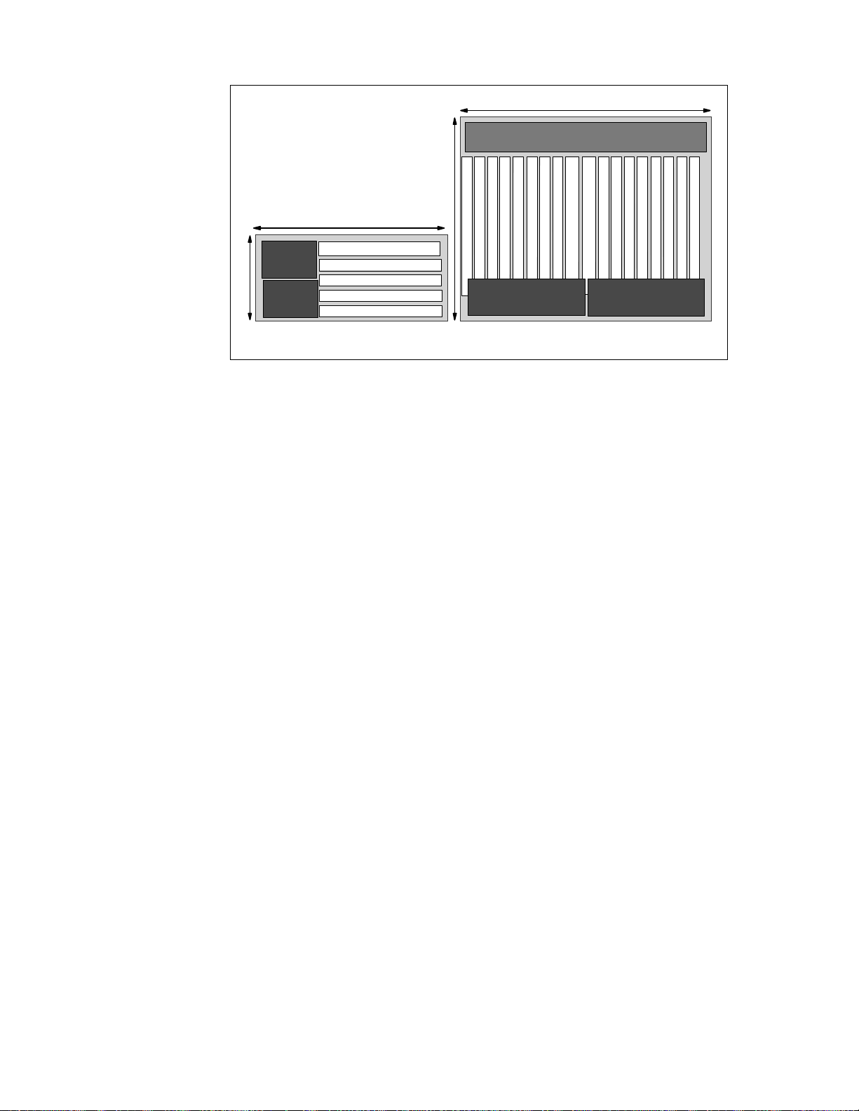
19"
19"
Cooli ng Fan Dr aw e r
21"
Power
Supply
Power
Supply
5.25"
IP Switch Control Board
IP Forwarding Media Card
IP Forwarding M edia Card
IP Forwarding Media Card
IP Forwarding Media Card
Control Bo ar d
IP Forwarding Media Card
IP Forwarding Media Card
IP Forwarding Media Card
IP Forwarding Media Card
IP Forwarding Media Card
IP Forwarding Media Card
IP Forwarding Media Card
Power
Supply
IP Switch Board
IP Forwarding Media Card
IP Forwarding Media Card
IP Forwarding Media Card
IP Forwarding Media Card
IP Forwarding Media Card
IP Forwarding Media Card
IP Forwarding M edia Card
IP Forwarding M edia Card
IP Forwarding M edia Card
Power
Supply
GRF 1600GRF 400
Figure 11. GRF Models
The SP Switch Router model 9077 04S (GRF 400) can accommodate up to
four media adapters.
The SP Switch Router model 9077 16S (GRF 1600) can accommodate up to
16 media adapters.
Each adapter enables the GRF to connect to one or more networks.
Each of the models has an additional slot for the IP Switch Control Board,
which is used to control the router.
GRF 400
PartDescription
Cooling Fan sThese are located on the right side of the chassis and cannot
be accessed without bringing down the GRF. T he
fans are redundant, allowing service to be
deferred until it is convenient to bring down the
GRF.
Media CardsThere are four media card slots on this chassis. They are
slotted horizontally and are located at the bottom
of the chassis.
IP Swit c h Control Boar dThis board is located at the top of the four media
slots and is also slotted horizontally.
Router Node 25
Page 44

Power Supply The left side of the chassis is reserved for the two power
supplies that are required for redundancy.
The failed power supply can be hot-swapped out of the GRF chassis.
GRF 1600
Part Description
Cooling Fan sThese are located at the top of the c hassis, and can be
accessed separately from the other parts of the
GRF. T he fan tray c ontains redundant fans and is
hot-swappable.
Media CardsThere are 16 media card s lots on this chassis. They are s lotted
vertically. Ei ght of the c ards are on the left side of
the chassis, and eight are on the right side.
IP Swit c h a n d
Control BoardThese boards are located in the middle of t he 16 m edia slots
and are also slotted vertically.
Power Supply The base of the chassis is reserved for the two power s uppl i es
that are required for redundanc y. The failed power
supply can be hot-swapped out of the GRF
chassis.
2.3.2 GRF Features
GRF has the following features:
• Redundant power supply
Should any power supply fail, a message is sent to the control board. The
power supply will automatically reduce its output voltage if the
temperature exceeds 90 °C (194 °F). If the voltage falls below 180V, the
GRF automatically shuts down.
• Hot-swappable power supply
The faulty power supply can be replaced while the GRF is in operation.
• Redundant fan
For the GRF 1600 model, if one fan breaks down, a message is sent t o the
control board.
For both models, when the temperature reaches 53°C (128 °F), an audible
alarm sounds continuously, and a message is sent to the console and
logged into the message log.
26 IBM 9077 SP Switch Router: Get Connec ted to the SP S witch
Page 45

If the temperature exceeds 57.5 °C (137 °F), the GRF does an automatic
system shutdown.
• Hot-swappable fan
For the GRF 16S model, the cooling fan can be replaced while the GRF is
in operation.
• Hot-swappable adapters
There are two types of adapters on the GRF: the media adapters and the
IP Switch Control Board.
The media adapters are i ndependent of each other and can be replaced or
removed without affecting any other adapter or the operation of the GRF.
However, the IP Switch Control Board is critical to the GRF. S hould this
board be unavailable, the router fails.
• Crosspoint switch
The crosspoint switch is a 16x16 (16Gb per second) or 4x4 (4Gb per
second) crossbar switch for the GRF 16S and GRF 04S, respectively, see
Figure 12 on page 27. It is the I/O path used when the media adapters
need to communicate with each other.
r
e
f
f
u
B
x
T
Media Interface
QBRT
CPU
Serial Interface
RT
ATM
MM
OC-3c
MM
OC-3c
IP/SO NET
CPU
r
e
f
f
u
B
x
R
............
..........
Combus
80 Mb/s bus
Out-of-Band
User Interface
Dynamic Routing Engine (Route Manager)
Configuration/Control
Figure 12. GRF Architecture
Some parts in Figure 12 need to be explained:
16MB Rx / 16MB Tx Buffers
Speed decoupling
WAN delays
QBRT Route Table Lookup
Times range from 1- 2.5 µs
On-Board Processor
IP Header
Route decisions
4 Gb/s Switch
Router Node 27
Page 46

1. Normally, all media cards have a 4 MB send buffer and a 4 MB receive
buffer, except the SP Switch Adapter card, which has a 16 MB buffer
size for each buffer. See also Section 2.3.5, “Characteristics of GRF
Media Cards” on page 36 and Figure 19 on page 37.
Quick Branch Routing Technology
2.
route table lookup. Route lookup times range from 1 - 2.5 µs with up to
150,000 next-hop routes in the table. Not all media cards use QBRT.
Cards that do not use QBRT use a microcode lookup.
The benefit of this architecture is that the entire route table can be
stored locally on the media card and s earched quickly. In the traditional
cached route table method, a small number of routes can be stored and
searched locally. However, when a large number of routes is desired,
or the kind of traffic one would see on the Internet backbone arises,
caching is inadequate. Inevitably, cache misses occur, and route table
lookups are performed at a limited, central, shared resource.
Performance is enhanced even further with parallel processing of table
lookups occurring on each media card, which is another technique that
helps assure linear scalability. The router manager on the controller
board, which also contains the switch fabric, maintains the master
route table and distributes updates simultaneously to all installed
media cards, even as the cards continue their forwarding functions.
3. On-Board Processor
4. Router management takes place on the IP Switch Control Board (see
Section 2.3.3.2, “IP Switch Control Board Components” on page 33),
based on a 166 Mhz Pentium processor. It is responsible for system
monitoring, configuration management and the user interface.
(QBRT) is a hardware-assisted
5. The G RF
for configuration, control and monitoring of media cards. The Combus
connects the IP Switch Control Board to the media cards independent
of the switch connection to each card. It is not used for routed data
between the cards. Route update packets received on any media card
are also sent across the Combus to the Route Manager and, therefore,
do not have to compete with normal IP traffic. The Combus is a serial
bus with a transferrate of 80 Mb/s and is FIFO-buf fered. The Arbitration
Logic is on the IP Switch Control Board.
2.3.2.1 Data Packet Proc essing
With the knowledge about the local routing functions of the media cards, we
now look at Figure 13 on page 29 to see how a dat a pack et is transferred
from one media card to another.
28 IBM 9077 SP Switch Router: Get Connec ted to the SP S witch
communications bus (Combus)
is an "out-of-band" data path
Page 47

External
Interface
External
Interface
DMA
CPU
QBRT
Tx Buffer
DMA
Rx Buffer
Internal
Interface
Figure 13. Data Packet Transfer
The routing can be divided into the following steps:
1. A data packet is received by the m edia c ard.
2. The packet is transferred to the receive buffer by the DMA engine.
3. The CPU exami nes the header and gives the destination address to the
route lookup hardware.
Tx Buffer
DMA
CPU
QBRT
DMA
Internal
Interface
Rx Buffer
Switch
Control Board
Dynamic
Route
Manager
4. The Q BRT finds the next hop in the route table.
5. A special header is added to the packet by the CPU. This header contains
information for the downstream card to process the packet, as well as the
next hop found by the QBRT.
6. The packet is then transferred to the internal serial interface by the DMA
engine.
7. A connection to the downstream c ard is set up through the sw itch.
8. The serial stream is converted back to parallel format by the downstream
card.
9. The packet is transferred to the transmit buffer by the DMA engine.
Router Node 29
Page 48

10.The header is examined by the CPU, which uses the infor mati on to buil d a
new header that will deliver the data across t he m edia inte rface.
11.The DM A engine transfers the packet to the media interface.
12.The packet is transferred across the media.
2.3.2.2 Routing Packet Process ing
The processing of packets with routing information is a little bit different from
the data packet processing procedure as you can see in Figure 14.
External
Interface
DMA
CPU
QBRT
Rx Buffer
DMA
Internal
Interface
Figure 14. Routing Packe t Proc essi ng
These are the steps for processing routing packets:
1. A routing packet is received by the media card.
2. The packet is transferred to the receive buffer by the DMA engine.
3. The CPU exami nes the header and gives the destination address to the
route lookup hardware.
4. The Q BRT finds the next hop in the route table.
5. A special header is added to the packet by the CPU. This header contains
information for the downstream card. The result of the hardware lookup
determines whether the packet should be forwarded to the Router
Manager.
Tx Buffer
Rx Buffer
External
Interface
DMA
CPU
QBRT
DMA
Internal
Interface
Tx Buffer
Switch
Control Board
Dynamic
Route
Manager
30 IBM 9077 SP Switch Router: Get Connec ted to the SP S witch
Page 49

6. The packet is then transferred to the Combus interface by the DMA
engine.
7. The packet is sent to the IP S witch Control Board’s Router Manager
across the Combus.
8. The Route M anager receives the packet and passes i t to the dy namic
routing software.
9. The packet is processed and global routing information is determined.
10.Route updates are broadcast across the Combus to all media cards
simultaneously.
11. Each card receives the update packet and m akes changes to its route
tables.
12.The packet is transferred across the media.
To ensure that dynamic routing packets are not dropped during times of
heavy congestion, precedence features are used. Routing packets are given
a high-priority tag and a user-configurable threshold for Tx buffers is
maintained for high-priority traffic.
2.3.3 IP Switch and Control Board
The control board, also known as the IP Switch Control Board, is accessed
through Telnet or a locally attached VT100 t erminal. The IP S witch Control
Board is supplied with the GRF and is necess ary f or i t s operat i on. The VT100
terminal is not supplied with the GRF. It is only needed for the installation of
the GRF.
Using terminal emulation software instead of looking for a real VT 100
terminal may be an alternative. You can use your Control Workstation or one
ATE
of your SP nodes. Install the
package (advanced terminal emulation) on
your RS/6000 and establish a serial connection between the system and the
router.
After installation, all future access to the GRF can be through Telnet to the IP
Switch Control Board’s administrative Ethernet.
The IP Switch Control Board is identified as slot 66 in both GRF models. A
sideview of the GRF 400 slot numbering scheme is shown in Figure 15 on
page 32.
Router Node 31
Page 50

Backplane
66
IP Switch Control Board
3
2
Slot numbers in decimal
for medi a cards
1
0
Figure 15. Side View of GRF 400 Cha ssis with Slo ts Number ed
The GRF 1600 has 16 media slots. The control board is located in slot 66, as
shown in Figure 16.
Backplane
Media cards
Slot numbers
0
1 2 3 4 5 6 7 8 9 10111213141566
Control board
Switch board
Figure 16. Top View of the GRF 1600 Chassis
The CPU in the IP Switch Control Board is a 166MHz Pentium processor and
runs a variant of BSD UNIX as its operating sys tem. For t hi s reas on, t he GRF
administrator is assumed to be proficient in UNIX.
The IP Switch Control Board is used to install, boot, and configure the router
and its media adapters.
It is also used for the logging of messages, the dumping of memory and
status, and to perform diagnostic checking of both the GRF and the media
adapters.
32 IBM 9077 SP Switch Router: Get Connec ted to the SP S witch
Page 51

2.3.3.1 Route Manager
As already mentioned, the router management takes place on the IP Switch
Control Board.
Specific functions of the Route Manager are:
• It processes all dynamic routing packets.
• It synchronizes the route tables on the media cards.
• It controls the media cards: issues interrupts and resets to individual
media cards and downloads executable programs and connection
information.
2.3.3.2 IP S witch Contro l Board Comp onents
Let us examine the IP Switch Control Board in more detail.
Figure 17 shows all the components of the IP Switch Control Board:
32MB
32MB
32MB
32MB
CPU
Pentium
166MHz
Figure 17. IP Switch Control Boar d
Admin Ethernet
32MB
32MB
System Bus
(de0)
32MB
32MB
PCMCIA
Card
Flash
Memory
(85 MB)
PCMCIA
Card
Router Node 33
Page 52

ItemDescription
MemoryThe IP S witch Control Board comes standard with 128 MB of
memory (the four shaded blocks of 32 MB of
memory in the upper left corner).
The memory can be upgraded to 256 MB, in i ncrements of 64 MB (the four
white blocks of memory).
The system uses the first 32 MB of memory for file system storage. The
top half is used for appl icat i ons s uch as the SNMP
agent, the gated daemon, and for the operating
system.
Flash memoryThis memory (the 85 MB ATA flash memory on t he system) is
used to store the operating system information
and the configuration information for the GRF.
System busThis bus is used by the I P Switch Control Board components to
communicate with each other.
Pentium processorThis 166 MHz processor drives the IP Switch Control
Board and the GRF. As previously mentioned, this
processor runs a variant of BSD UNIX, and so it is
useful for the GRF administrator to have UNIX
management skills.
Administrative EthernetThis Ethernet is known t o the GRF as de0. This port
supports the 10BaseT or the 100BaseT Ethernets
and switches between them automatically,
depending on the type of network used.
To use 10Base2 or 10Base5, the user must add a transceiver (supplied by
the user).
PCMC IA c a rdsThe t wo white blocks at the bottom right corner of the figure
are PCMCIA slots.
There are two types of PCMCIA cards:
• Slot A on the 9077 is configured with a 520 MB disk drive. This disk is
used to hold the log of the GRF. It may also be
used to backup the configuration of the GRF.
Making a backup is strongly recommended.
• The PCMCIA modem card, also available as an optional device, allows
the user to dial into the GRF through a modem
to administer it remotely.
Note: For the initial setup, the console must be available locally, not
through the modem.
34 IBM 9077 SP Switch Router: Get Connec ted to the SP S witch
Page 53

Additionally, the RS232 port (which is not shown in the figure) allows you to
connect the VT100 console by using an RS232 null modem cable. The
console and cable must be supplied by the user.
2.3.4 Memory Gu idelines for t he IP Switch Co ntrol Board
As already mentioned, the GRF base system comes with 128 MB of memory.
In all GRF memory configurations, 32 MB are used for t he fil e system and the
remainder is used for system operations. For example, in the base system,
there are 128 MB of total memory, 32 MB of available memory and 78 M B of
usable memory. (Refer to Table 1 on page 35 for detailed memory
configuration information). Up to six additional 32 MB DRAM SIMMS m ay be
added to support larger dynamic routing tables and larger numbers of peers
(for a total of 256 MB, 204 MB usable).
The following table provides guidelines for memory configuration. All media
cards can hold up to 150 KB route entries. The control board, depending on
memory configuration, can hold 35,805 to 521,730 route prefixes. Select the
amount of memory according to your r outing environment. Additional memory
may be required for higher average numbers of routes per BGP peer.
Table 1. Memory Con figuration
Customer
Profile
Total
Mem.
Avail. Usable No. of
Route
Entries
on
Media
Cards
No. of
Route
Prefixes
in
Dynamic
Database
No. of
Peer
Sess.
Static Routing 64 MB 32 MB 14 MB 150 KB 35805 0
Small POP 128 MB 96 MB 78 MB 150 KB 199485 3
Medium POP/
ISP Backbone
Large POP/
Exchange Point/
Route Reflection
Server
192 MB 160 MB 142 MB 150 KB 362165 7
256 MB 224 MB 204 MB 150 KB 521730 10
Figure 18 gives an overview of the memory layout and the possible memory
extensions.
Router Node 35
Page 54

64MB RAM
32MB
(fixed size)
64MB RAM
64MB RAM
- System software
64MB RAM
- Config files
- Gated binary
20MB
8-12MB
(fixed size)
Figure 18. System RAM
- Route table
- Kernel runs
- Gated runs
2.3.5 Characteristics of GRF Media Ca rds
All GRF media cards (media adapters) are self-contai ned and independent of
other media adapters.
Each media card has an onboard processor that is responsible for IP
forwarding on the media adapter.
Each media card has two independent memory buffers, a 4 MB send buffer
and a 4 MB receive buffer. These buffers are necessary to balance the speed
differences between t he m edi a adapt ers, because they have di f ferent transfer
rates.
Each onboard processor has local memory that can contain a local route
table with up to 150,000 entries, to be used for routing on the media adapter.
Because these route entries are in local memory, access to them is very fast.
When the media adapter is started up, it gets its initial route entries from the
IP Switch Control Board.
= expandable area of RAM
2.3.6 SP Switch Router Adapter
The GRF supports a number of media adapters. Figure 19 describes the SP
Switch Router Adapter in detail. This adapter allows the GRF to connect
directly into the S P S w itc h.
36 IBM 9077 SP Switch Router: Get Connec ted to the SP S witch
Page 55

Crosspoint
Switch
Media Board
Receive
7
6
5
4
3
2
1
0
TBIC
Receive
Proc & C
Send
TBIC
SP Switch
Figure 19. SP Switch Router A dapte r
16MB
Buffer(1)
Send
Proc & C
16MB
Buffer(2)
FIFO
(1)
FIFO
(2)
Serial
Daughter
Card
The SP Switch Router Adapter is made up of two parts: the media board and
a serial daughter card.
The serial daughter card is an interface for the media board into the
crosspoint switch. This switch is the medium by which the GRF (media)
adapters talk to each other.
The purpose of the media board is to route IP packets to their intended
destination through the GRF. The SP Switch Router adapter described here is
used for routing IP packets to and from the SP Switch to other systems
connected directly or indirectly to the GRF. A brief description of the
components on the media board follows.
Receive TBICThis component receives data segments from the SP S witch
and notifies the Rec ei ve Cont rol ler and Processor that
there is data to be transferred to the buffer.
Router Node 37
Page 56

Receive Controller
and ProcessorThis component recognizes the SP Switch segments and
assembles them into IP packets in the 16 MB buffer.
Up to 256 IP datagrams can be handled
simultaneously. When a complete IP packet has been
received, the Receive Controller sends the packet to
the FIFO (1) queue for transfer to the serial daughter
card.
Buffer (1)This component is segmented into 256 64 K B IP packet buffers. It
is used to reassemble IP packets before sending them
to the FIFO queue, as switch data segments may
arrive out of order and interleaved with segments
belonging to different IP packets.
FIFO (1) This component is used to transfer complete IP packets to the serial
daughter card and even the flow of data between the
SP and GRF crosspoint switch.
FIFO (2) This component receives IP packets f rom the serial daughter card
and transfers them to Buffer (2).
Buffer (2)This buffer is used to temporarily store the IP packet while its IP
address is examined and a proper SP Switch route is
set up to transfer the packet through the SP Switch.
Send C ontroller
and ProcessorThis component is notified when an IP packet is received in
the FIFO (2) queue and sets up a DMA transfer to
send the packet to Buffer (2). The Send Processor
looks up the IP address in the packet header and
determines the SP Switch route for the packet, before
notifying the Send Controller to send the packet to the
Send TBIC from Buffer (2).
Send TBICThis component receives data from Buffer (2) and sends it in SP
Switch data segments to the SP Switch.
2.3.7 Media Card P erformance
The SP Switch Router adapter has the following performance characteristics:
• It is able to transfer up to 100 MB per second. The limiting factor is the
crosspoint switch connection bandwidth.
38 IBM 9077 SP Switch Router: Get Connec ted to the SP S witch
Page 57

• It is able to transfer up to 30,000 packets per second. At 20,000 packets
per second, each packet needs to be at 5 KB in order to achieve the 100
MB per second transfer rate mentioned.
• As previously mentioned, each adapter stores its own route tables in
memory. Therefore, route table lookup is very fast, that is, less than 2.5
µs.
• Finally, each media adapter has a 1 Gbit per s econd dedicated link into
the crosspoint switch. That is why the 4-port and 16-port models have an
aggregate bandwidth of 4 Gbit and 16 Gbit per second, respectively, for
the crosspoint switch.
2.3.8 Other Media Cards
The following are other media cards and adapters currently supported on the
GRF:
EthernetThe 10/100 Mb Ethernet media adapter consists of eight
ATM OC-3cT he ATM OC-3c media adapter allows the user to connect up to
10/100BaseT Ethernet ports. All ports support only shielded
twisted pair (S T P) and unshielded twisted pair (UTP-5) copper
cables. Other types of cables require the user to supply the
appropriate transceivers.
two connections into the ATM network at 155 Mb/s.
ATM OC-12cThe ATM OC-12c media adapter allows the GRF to connect to a
single ATM network at speeds of up to 622 Mb per second.
FDDIThe FDDI media card provides four ports in the card. These ports allow
the media card to be connected into t he F iber Distributed Data
Interchange (FDDI). The four ports can be configured such
that they support the following:
• Two dual-ring FDDI networks
• One dual-ring and two single-ring FDDI networks
• Four single-ring FDDI networks
HIPPIThe HIPPI media adapter is a single-port card that allows the GRF to
connect to a High Performance Parallel Interface (HIPPI)
network at speeds of up to 800 or 1600 Mb/s. After deducting
the overhead, this medium can support connections of up to
100 MB/s.
HSSIThe High Speed Serial Interface (HSSI) is a dual-ported media adapter
that can connect to two serial networks simultaneously. Each
port is capable of up to 45 Mb per second.
Router Node 39
Page 58

IP/SON ETThe IP/SONET OC-3c is a single-ported card that allows the user
to connect to a digital network using a transmission format
known as Synchronous Optical Network protocol (SONET).
This standard is increasingly popular in the
telecommunications industry.
2.3.9 GRF Operating Environment
As previously mentioned, the operating temperature should not exceed 53 °C
(128 °F). Even though there is a buffer between the operating temperature
and the warning temperature, it is best to keep the temperature within the
operating level in order to minimize the possibility of damage to GRF
components.
2.4 PSSP Enhancements
This section discusses the enhancements made to PSSP to accommodate
the Dependent Node Architecture.
2.4.1 SDR Enhancements
As mentioned in Section 2.1.2, “Design Objectives” on page 8, the System
Data Repository (SDR) needed to be extended to support the dependent
node architecture. Two classes have been added to the SDR.
• DependentNode
• DependentAdapter
2.4.1.1 DependentNode Attrib utes
The attributes of the DependentNode class are described in Table 2:
Table 2. DependentNode Attribute s
User Defined System Defined
node_number switch_node_number
extension_node_identifier switch_number
reliable_hostname switch_chip
management_agent_hostname switch_chip_p ort
snmp_community_name switch_partition_number
40 IBM 9077 SP Switch Router: Get Connec ted to the SP S witch
Page 59

The attributes of the DependentNode class are described in detail as follows:
AttributeDescription
node_numberThis user-supplied node number represents the node position
of an unused SP Switch por t used for the SP
Switch router adapter.
extension_node_identifierThis is a 2-digit slot number that the SP Switch
router adapter occupies on the GRF. I ts
range is from 00 to 15.
reliable_hostnameThe hostname of the administrative Ethernet, de0, is the
GRF’s hostname. Use the long version of
the hostname when DNS is used.
management_ a gent_hostnam eThis attribute is the hostname of the SNMP
agent for the GRF. For the GRF dependent
node, this is the same as the
reliable_hostname.
snmp_community_nameThis field contains the SNMP community name that
the SP Extension Node SNMP Manager and
the GRF’s SNMP Agent will s end in t he
corresponding field of the SNMP messages.
This value must match the value specified in
the /etc/snmpd.conf file. If left blank, a
default name found in the SP Switch Router
Adapter documentation is used.
The following attributes are derived by the RS/6000 SP system when the
SDR_config routine of
endefnode is invoked.
AttributeDescription
switch_node_numberThe switch port that the dependent node is attached
to.
switch_numberThe switch board that the dependent node is attached to.
switch_chipThe switch chip that the dependent node is attached to.
switch_chip_portThe switch chip port that the dependent node is attached
to.
switch_partition_numberThe partition number to which the dependent node
belongs.
Router Node 41
Page 60

2.4.1.2 DependentAdapte r Attributes
The attributes of the DependentAdapter class are described in Table 3:
Table 3. DependentAda pter Attribute s
User Defined System Defined
node_number netaddr netmask -
The attributes of the DependentAdapter class are described in detail as
follows:
AttributeDescription
node_numberThis user-supplied node number represents the node position
of an unused SP Switch port to be us ed by the SP S witch
router adapter.
netaddrThis is the IP address of the SP Switch Router adapter.
netmaskThis is the netmask of the S P Switch Router adapter.
2.4.1.3 Additional Attributes
As Table 4 s hows, additional attributes are added to the Syspar_map_class
and the Switch_partition classes:
Table 4. Additional SDR Attributes
Syspar_map class Switch_partition class
... ...
node_type switch_max_lt u
Details of these attributes follow:
42 IBM 9077 SP Switch Router: Get Connec ted to the SP S witch
switch_link_delay
Page 61

AttributeDescription
node_typeThis attribute is set to
switch_max_ltuThis specifies the maximum packet length of data on the SP
switch_link_delaySpecifies the delay for a message to be sent between the
2.4.2 New Commands
To support the dependent node architecture, seven new commands were
added. These commands can be divided into two groups. The first group
must only be executed with root permission on the Control Workstation. The
second group can be executed by any user on any standard RS/6000 SP
node.
Table 5 shows a list of commands of t he first group:
Table 5. New Comm ands (root E xe cutable )
Command Description
endefnode Define or change an dependent node
enrmnode Remove a dependent node
dependent
for GRF and to
standard
for all
other RS/6000 SP nodes.
Switch; the default is 1024.
any reason
.
Do not change this value for
two furthest points on the switch; the default is 31.
not change this value for any reason
.
Do
endefadapter Define or change an dependent node
enrmadapter Remove an dependent node adapter
enadmin Reconfigure or reset the dependent node
The first four commands all have the same characteristics, which are as
follows:
• The are part of the ssp.basic fileset.
• They must only be executed on the Control Workstation.
• They can only be executed by the root user.
• They only affect the current active partition.
• They only affect the SDR, unless the
not applicable to
enrmadapter).
-r option is specified (this option is
• They return a code of 0 if successful, 1 if failed.
Router Node 43
Page 62

The enadmin command is used to change the administrative state of a
dependent node in the GRF; it has the following characteristics:
• It is part of the ssp.spmgr fileset.
• It must only be executed on the Control Workstation.
• It can only be executed by the root user.
• The
-r option from endefnode and endefadapter triggers enadmin -a
reconfigure
, while the -r opt ion from enrmnode triggers enadmin -a reset.
• The return code is 0 if successful, 1 if failed.
Table 6 shows the list of commands from the second group (executable by
any user on any standard node):
Table 6. New Comm ands (U ser E xec utable )
Command Description
splstnodes List SP nodes
splstadapters List SP adapter
These commands have the following characteristics:
• They are part of the ssp.basic fileset.
• They can be executed on any standard RS/6000 SP node.
• They can be executed by any user.
• They only affect the current active partition unless the
-G option is used.
The following sections describe the commands in more detail.
2.4.2.1 The endefnode Com mand
endefnode command can be executed using smit. The fast path for smit is
The
enter_extnode. This command is used t o add or change an extension node in
the SDR DependentNode class. Its options are shown in Table 7 on page 45.
44 IBM 9077 SP Switch Router: Get Connec ted to the SP S witch
Page 63

Table 7. endefnode Co mma nd Op tions
Flags SMIT Optio n Desc rip t io n
-a Administ rative hostname This is the hostname of the GRF, and the IP nam e
of the GRF’s administrative Ethernet, de0. Use
long names if DNS is used in the network.
-c SNMP community name This field contains the SNMP community name
that the SP extension node SNMP Manager and
the GRF’s SNMP agent send in the
corresponding f iel d of the SNMP mess ages. This
value must match the value specified in the
/etc/snmpd.conf file on the GRF . If left blank, a
default name found in the SP Switch Router
Adapter documentation is used.
-i Extension node
This field contains the two-digit slot
number of the SP Switch Router Adapter
on the GRF. The value for this field is from
00-15 and is shown on the slots of the
GRF.
-s SNMP Agent hostname
This field refers to the hostname of the
processor running the SNMP Agent for t he
GRF . In the current version of the GRF, this
value is equivalent to that of the
Admi ni st rat ive Ho stn ame .
-r Reconfigure the
extension node
This field specifies whether the enadmin
command is to be activated after the
endefnode command completes. I t is placed
here so that the user does not have to
enadmin command. If the
yes, the -r option i s part of
no, the
Node number
explicitly issue the
specification is
the command. If the specification is
-r option is not part of the command.
This is the node number the extension
node logically occupies in the RS /6000 SP.
This command adds attribute information for the extension node. The
endefadapter command adds IP information, such as the IP address and
netmask for the extension node. Together, these two commands define the
extension node.
Router Node 45
Page 64

Atten ti o n
Note that this command only affects the SDR, unless the -r option is used.
-r option should be issued only if endefadapter has been executed for
The
the extension node.
When the GRF is properly configured and powered on, with the SP Switch
Router Adapter inside, it periodically polls the Control Workstation for
configuration data. The
-r option or en admin command is not required to
activate the polling here.
2.4.2.2 The enrmnod e Command
enrmnode command is used to remove an extension node from the SDR
The
DependentNode class and can also be executed using smit. The fast path for
smit is
Table 8. enrmnode Com man d Opti ons
delete_extnode. Its options are shown in Table 8.
Flags SMIT Option Description
-r
Reset the
extension node
Specifies whether the
activated after the
enrmnode command
enadmin command is to be
completes. With this option the user does not
have to explicitly issue the
the specification is
yes, the -r option is part of the
command. If the specification i s
enadmin command. If
no, the -r opti on
is not part of the command.
Node number This is the node number the extension node
logically occupies in the RS/6000 SP.
Attention
Note that this command only affects the SDR, unless the -r option is used.
This command should be issued with a
command is not available for the extension node after
-r flag, because the enadmin
enrmnode is executed,
since the extension node has been removed from the SDR.
46 IBM 9077 SP Switch Router: Get Connec ted to the SP S witch
Page 65

2.4.2.3 The endefadapt er Command
The
endefadapter command is used to add or change the extension node
adapter IP information in the SDR DependentAdapter object, and can be
executed using
smit. The fast path f or smit is enter_extadapter . The command
options are shown in Table 9.
Table 9. endefadapter Comman d Op tions
Flags SMIT Option Description
-a
Network
Specifies the IP address of the extension node.
address
-m
Network
Specifies the netmask for the extension node.
netmask
-r
Reconfigure
the extension
node
Specifies if the
activated after the
enadmin command is to be
endefadapter command
completes. With this option, the user does not
have to explicitly issue the
the specification is
yes, the -r option is part of the
command. If the specification i s
enadmin command. If
no, the -r opti on
is not part of the command.
Node number
This is the node number the extension node
logically occupies in the RS/6000 SP.
Attention
Note that this command only affects the SDR, unless the -r option is
issued. The
-r option should be issued only if the endefnod e has been
executed for the extension node.
When the GRF is properly configured and powered on, with the SP Switch
Router Adapter inside, it periodically polls the Control Workstation for
configuration data. The
-r option or enadmin command is not required to
activate the polling here.
2.4.2.4 The enrmadap ter Command
enrmadapter command is used to remove the SDR DependentAdapter
The
object, and can also be executed using smit. The fast path for smit is
delete_extadapt er.
Router Node 47
Page 66

2.4.2.5 The enadmin Com mand
The
enadmin command is used to change the status of the SP Switch router
adapter in the GRF and can also be executed using smit. The fast path for
smit is
Table 10. enadm in C omm and O ptions
manage_extnode. The command options are s hown in Table 10.
Flags SMIT Option Description
-a
Actions to be
performed on
the extension
node
Either
reset or re configure. A reset is s ent to the
extension node SNMP Agent to change the
target node to a down state (not active on the SP
Switch ) . A
reconfigure is sent to the extension
node SNMP Agent to trigger reconfiguration of
the target node, which causes the SNMP Agent
to request new configuration parameters from
the SP extension node SNMP Manager, and to
reconfigure the target node when the new
parameters are received.
Node number
This is the node number the extension node
logically occupies in the RS/6000 SP.
48 IBM 9077 SP Switch Router: Get Connec ted to the SP S witch
Page 67

2.4.2.6 The splstno des Co mmand
The
splstnodes command is used to list the node attributes of all nodes in the
SDR, and can also be executed using smit. The fast path for smit is
list_extnode. See all command options in Table 11.
Table 11. splstnode Command Options
Flags Description
-h
-G
-x
-d <delimiter>
-p <string>
Outputs usage information.
Ignores partition boundaries for that output.
Inhibits header record in the output.
Uses the <delimiter> between its attributes in the output.
Uses the <string> value in the output in place of an
attribute that has no value.
-s <attr>
Sorts the output using the <attr> value. In SMIT, this field
is known as Sort Attribute.
-t <node_type> Uses standard to list RS/6000 SP nodes, or dependent. If
none is specified, it displays standard and dependent. In
SMIT, this field is known as Node Type.
-N <node_grp>
Restricts the query to the nodes belonging to the node
group specified in <node_grp>. If the <node_grp>
specified is a system node group, the -G flag is implied.
<attr==value>
This operand is used to filter the output, such that only
nodes with attributes that are equivalent to the value
specified are displayed. In SMIT, this field is known as
Query Attribute.
<attr>
This is a list containing attributes t hat are displayed by the
command. If none is specified, it defaults to node number.
This list of attributes can be found in the DependentNode
class. In SMIT, this field is known as A ttribute.
Router Node 49
Page 68

2.4.2.7 The splstadapters Comm and
The
splstadapers command is used to list the adapter attributes of all nodes in
smit
the SDR, and can also be executed using
list_extadapter . See all command options in Table 12.
Table 12. splstad apter Comm and O ptions
Flags Description
. The fast path for smit is
-h
-G
-x
-d <delimiter>
-p <string>
Outputs usage information.
Ignores partition boundaries for its output.
Inhibits header record in the output.
Uses the <delimiter> between its attributes in the output.
Uses the <string> value in the output in place of an
attribute that has no value.
-t <node_type> Uses standard to list RS/6000 SP nodes, or dependent. If
none is specified, it displays standard and dependent. In
SMIT, this field is known as Node Type.
<attr==val ue>
This operand is used to filter the output, such that only
nodes with attributes that are equivalent to the value
specified are displayed. In SMIT, this field is known as
Query Attribute.
<attr>
This is a list containing attributes t hat are displayed by the
command. If none is specified, it defaults to node number.
This list of attributes can be found in the Adapter and
DependentAdapter class. In SMIT, this field is known as
Output Attribute.
50 IBM 9077 SP Switch Router: Get Connec ted to the SP S witch
Page 69

2.4.3 Enhanced Commands
The following commands (see Tabl e 13) have been m odified due t o the
introduction of the dependent node:
Table 13. En hance d Co mma nds
Command Comment
Eprimary The dependent node cannot be the Primary node.
Estart The dependent Node dep ends on the Primary node to calculate the
routes.
Efence Enhanced for dependent node support.
Eunfence Enhanced for dependent node support.
Here is a more detailed description about the modifications:
•Eprimary
This command has been modif ied so t hat dependent nodes will not be
able to act as a Primary or Primary Backup node for the SP Switch in the
partition. The dependent node does not run the RS/6000 SP Switch codes
like standard RS/6000 SP nodes and therefore does not have the ability to
act as the Primary or Primary Backup node.
•Estart
This command functions as it does with normal nodes. It was enhanced to
support the depend node in the RS/6000 SP.
•Efence
This command functions as it does with normal nodes in the RS/6000 SP.
In addition, the dependent node can be fenced from the SP Switch with
autojoin like any other standard RS/6000 SP node.
•Eunfence
This command functions as it does with normal nodes in the RS/6000 SP.
In addition, the dependent node can r ej oin the S P Switc h net work w ith t hi s
command, if that node was previously removed from the switch network
due to failures or
Efence.
Router Node 51
Page 70

2.4.4 Hard war e Pe rsp ecti ves
In Perspectives
easily displayed in the GUI. It conveys the role and functions of the
dependent node. Currently, this is the only dependent node.
In Figure 20 we show the changes made to Perspectives because of the
introduction of the IP Node. The changes are restricted to the Hardware and
System Partition Aid Perspectives.
IP Node
1
2
3
is used as a convenient and short descriptive term
4
Figure 20. Hardware Perspec tives
This figure shows the Hardware Perspectives , which c an be started using the
command
be started directly via the command
The Hardware Perspective consists of the following four parts:
1. Menu bar
2. Toolbar
52 IBM 9077 SP Switch Router: Get Connec ted to the SP S witch
perspectives and selecting the Hardware icon. Alternatively, it can
sphardware.
Page 71

3. Nodes pane (Frame or Icon View)
4. Information area
The most obvious change is the addition of the IP Node icon as seen in the
Nodes pane. (The figure above shows the Frame View.) The default label for
this icon is IP Node <node number>.
The IP Node icon is also located on the side of the frame, where a standard
node with that node number would be. In this figure the IP Nodes are 7, 14
and 15.
When switch_responds is monitored, it shows the IP Node in two states:
• Green when working with the SP Switch.
• Marked with a red cross when fenced or not operating due to hardware or
configuration problems.
In the figure, IP Node 7 and 15 are working, while IP Node 14 is down.
2.4.4.1 Action Menu
In Figure 21 on page 54, we see that IP N ode 7 is selected in the Nodes
pane, and Actions->Nodes is selected in the menu bar (1). We see that only
the following five actions are available:
Router Node 53
Page 72

1
2
3
4
Figure 21. Action Menu
•View
This will bring up the IP Node’s hardware notebook, shown in the next
figure.
• Fence/Unfence...
This will bring up another window to allow us to either fence or unfence an
IP Node. If we are fencing the IP Node, we can use the option of autojoin.
• Create Node Group...
This will bring up another window to allow us to add the R S/6000 SP
nodes to a Node Group. This action does not affect the IP Node, even
though it is selectable.
• 3 Digit Display
54 IBM 9077 SP Switch Router: Get Connec ted to the SP S witch
Page 73

This will bring up a w indow to show the thr ee-digit display of all R S /6000
SP standard nodes in the current partition. This action does not apply to
the IP Node, even though it is selectable.
• Open Administrative Session...
This action will open a window t hat is a Telnet session to the GRF, using
the reliable_hostname attribute specified in the DependentNode class.
In addition, the Nodes pane in this figure shows the Icon View. In this view,
the IP Node icons are always located after all the standard RS/6000 SP node
icons. The results of monitoring the IP Nodes and the icon labels are the
same as those of Frame View, mentioned in the previous figure.
2.4.4.2 Hardware Noteboo k
Figure 22 shows the IP Node hardware notebook. This notebook can be
triggered by selecting the Notebook icon on the Hardware Perspective
toolbar (2), or selecting Action->Nodes->View in the menu bar (1).
Figure 22. Hardware Noteboo k
The notebook has three tabs: Configuration, All Dynamic Resource Variables,
and Monitored Conditions. This figure shows the Configuration tab.
Router Node 55
Page 74

These are the attributes listed in the Configuration tab:
• Node number
• Hostname
• Management agent hostname
• SNMP community name
• System partition
• Extension node identifier
• Dependent node IP address
• Dependent node netmask
• Switch port number
• Switch number
• Switch chip
• Switch chip port
• Switch partition number
• Switch responds
The All Dynamic Resource Variables tab only shows the state of the Switch
Responds, and the Monitored Conditions tab only shows the value of the
Switch Responds
if it is being monitored.
2.4.4.3 System Partition Aid Persp ectives
The System Partition Aid Perspectives window in Figure 23 on page 57 has
two panes, the Nodes pane and the System partitions pane. The Nodes pane
(3) in this figure shows the Icon view. Notice that the IP Nodes are displayed
after all the standard RS/6000 SP nodes.
56 IBM 9077 SP Switch Router: Get Connec ted to the SP S witch
Page 75

1
2
3
4
Figure 23. System Partition Aid Pe rspectiv es
The IP Nodes can only be assigned to a partition here. This is done either by
using the Assign icon in the toolbar (2), or by selecting
Action->Nodes->Assign Nodes to System Partition on the menu bar (1).
Except for the System Partition Notebook, discussed in the next figure, all
other actions, though selectable, do not apply to the IP Node.
2.4.4.4 System Partition Aid Notebook
Figure 24 on page 58 shows the IP Node System Partition Aid Notebook. This
notebook can be triggered by selecting the Notebook icon on the Hardware
Perspective toolbar (2), or selecting Action->Nodes->View on the menu bar
(1).
The notebook only has the Node Information tab shown in this figure.
Router Node 57
Page 76
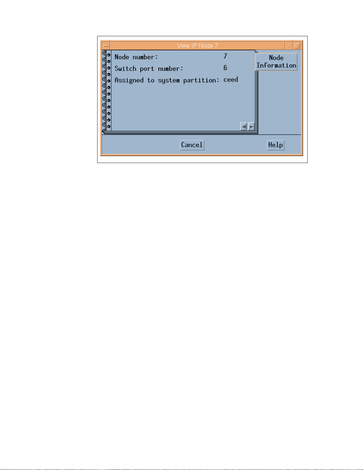
Figure 24. System Partition Aid Note book
These attributes are listed in the Node Information tab:
• Node number
• Switch port number
• Assigned to system partition
2.4.5 SP Extension No de SNMP M anager
The SP Extension Node SNMP manager is contained in the ssp.spmgr file set
of PSSP. This file set must be install ed on t he Control Workstation in order for
the GRF to function as an extension node.
The SP Extension Node SNMP manager is an S NMP m anager admini stered
by the System Resource Controller. The purpose of the SNMP manager is to
communicate with the SNMP agent on the GRF. The SNMP manager and the
agent adhere to Version 1 of the SNMP protocol. The SNMP manager sends
configuration data for an extension node to the SNMP agent on the GRF. The
SNMP agent applies the configuration data to the SP Switch Router Adapter
represented by the extension node. The SNMP agent also sends
asynchronous notifications in the form of SNMP traps to the SNMP Manager
when the extension node changes state. The following commands are
available to control the SP Extension Node SNMP Manager:
•startsrc
58 IBM 9077 SP Switch Router: Get Connec ted to the SP S witch
Page 77

•stopsrc
•lssrc
•traceson
•tracesoff
2.4.6 Dependent N ode MIB
IBM has defined a dependent node SNMP Management Information Base
(MIB) called ibmSPDepNode. This MIB contains definitions of objects
representing configuration attributes of each dependent node and its state.
The GRF Agent maintains the state and configuration data for each
dependent node using the MIB as a conceptual database.
The MIB defines a single table of up to 16 entries representing the adapter
slots in the GRF. When a slot is populated by an SP Switch Router Adapter,
the entry in the table, accessed using the extension node identifier, contains
the configuration attribute and state values for the adapter in the slot. Also
included in the MIB are the definitions of trap messages sent by the GRF
agent to the SP Extension Node SNMP Manager. A copy of the MIB is
contained in the file /usr/lpp/ssp/config/spmgrd/ibmSPDepNode.my
Control Workstation.
Other SNMP managers in the network can query this MIB table to validate the
configuration and status of the dependent node and GRF. However, only an
SNMP manager using the correct SNMP community name c an change the
values in the MIB table.
on the
Following is a listing of MIB entries:
Entry D ef ini t ion
ibmSPDepNodeObject identifier for the dependent node in the MIB
database.
ibmSPDepNodeTableTable of entries for dependent nodes.
ibmSPDepNodeEntryA list of objects comprising a row and a clause in
ibmSPDepNodeTable. The clause indicates
which object is used as an index into the table to
obtain a table entry.
ibmSPDepNodeNameThe extension_node_identifier attribute in the
DependentNode class.
ibmSPDepNodeNumberThe node_number attribute in the DependentNode
class.
Router Node 59
Page 78

ibmSPDepSwTokenA combination of switch_number, switch_chip and
switch_chip_port attributes from the
DependentNode class.
ibmSPDepSwArpThe arp_enabled attribute in the Switch_partition class.
ibmSPDepSwNodeNumberThe switch_node_number attribute in the
DependentNode class.
ibmSP DepIPad dr The netaddr attribute in the DependentAdapter class.
ibmSPDepNetMaskThe netmask attribute in the DependentAdapter class.
ibmSPDepIPMaxLinkPktThe switch_max_ltu attribute in the Switch_partition
class.
ibmSPDepIPHostOffsetThis attribute stores the diff erence bet ween the host
portion of a node’s IP address and its
corresponding switch node number. When ARP
is disabled on the SP Switch network, this offset
is subtracted from the host portion of the IP
address to calculate the switch node number.
ibmSP DepConf ig St a teThe six config states of the dependent node are:
notConfigured, firmwareLoadFailed,
driverLoadFailed, diagnosticFailed,
microcodeLoadFailed, and fullyConfigured, for
use in configuring the adapter.
ibmSPDepSysNameThe syspar_name attribute in the Syspar class.
ibmSPDepNodeStateThe value of nodeUp or nodeDown, to show the status
of the dependent node.
ibmSP De p SwChipLink The switch_chip_port attribute in the D ependentNode
class.
ibmSPDepNodeDelayThe switch_link_delay attribute in the Switch_partition
class.
ibmSPDepAdminStateThe value of up, down, or reconfigure, indicating the
desired state of the dependent node. If the
dependent node is not in its desired state, the
SNMP agent on the GRF will trigger the
appropriate action to change its state.
2.4.7 Coexistence
Figure 25 shows a single-frame RS/6000 SP in a single partition with a
connection to the GRF. Nodes 1 and 2 are installed with PSSP 2.4. The other
nodes are installed with any other version of PSSP that can coexist with
60 IBM 9077 SP Switch Router: Get Connec ted to the SP S witch
Page 79

PSSP 2.4 to represent coexistence. Also, note that Node 16 is empty,
because the SP Switch port for this node is used by the SP S witch router
adapter in the GRF.
PSSP 2.4 or PSSP2.3 and IX70649 on
CWS
Primary switch node
Backup switch node
PTFs for all other nodes
for PSSP2.1 IX71246
for PSSP2.2 IX71245
ssp.spmgr file set installed on CWS
Must be an SPS or SPS-8 swi tc h
SP Switch Router Cable
Ethernet
Cable
RS232
Cable
CWS
PSSP 2.4
IP Switch
Control
Board
SP Switch
4-port FDDI
Crosspoint
GRF 400
Switch
Switch
Frame
PSSP
16
*.*
PSSP
14
*.*
12
PSSP
*.*
10
PSSP
*.*
8
PSSP
*.*
PSSP
6
*.*
PSSP
4
*.*
PSSP
2
2.4
PSSP
15
*.*
PSSP
13
*.*
11
PSSP
*.*
9
PSSP
*.*
7
PSSP
*.*
PSSP
5
*.*
PSSP
3
*.*
PSSP
1
2.4
Figure 25. Coexistence
The dependent node is only supported in PSSP 2.3 and higher PSSP
versions. To use it with nodes with PSSP versions less than 2.3 requires the
use of
coexistence
. The following conditions are required for the dependent
node to communicate with nodes with a lower version than 2.3 using
coexistence:
• The Control Workstation must be at PSSP 2.3 or higher to manage
dependent nodes.
• The Primary node of the SP Switch must be at PSSP 2.3 or higher, as the
Primary node needs to perform some tasks for the dependent node and
these functions are only available in PSSP 2.3 and higher PSSP versions.
• The Primary Backup node of the SP Switch should be PSSP 2.3 or higher
so that if the Primary node fails, the dependent node can continue to
function in the RS/6000 SP when the Backup node takes over.
Router Node 61
Page 80

• All RS/6000 SP nodes with a version less than PSSP 2.3 in the partition
need to maintain the right level of fixes (PTFs) in order for coexistence
with PSSP 2.4 to take place.
• The ssp.spmgr file set must be installed on the Control Workstation.
• Because the SP Switch router adapter will only work with the 8-port or
16-port SP Switch, make sure that the switch used in the RS/6000 SP is
not a High Performance Switch (HiPS).
• There must be at least one free SP Switch port to install the SP Switch
router adapter.
Important
When the Primary switch node fails, the Primary Backup Switch node take
over as the new Primary switch node. The new Primary Backup switch
node, selected from the current partition, can be a node with a PSSP level
below 2.3, even though another node with a PSSP level of 2.3 or higher
may exist in that partition. The only way to ensure that the new Backup
switch node is at PSSP 2.3 or higher is to manually check the RS/6000 SP
system. If the PSSP Version of the Primary Backup switch node is below
Version 2.3 you have to chose a node with PSSP 2.3 or higher as the
Primary Backup switch node.
If a node running a version of PSSP earlier then 2.3 is selected as the new
primary node, the SP Switch Router Adapter will be fenced from the switch.
2.4.8 Partitioning
Figure 26 on page 63 shows a single-frame RS/6000 SP broken into two
partitions, Partition A and Partition B. Each partition has seven standard
RS/6000 SP nodes and one dependent node. Only seven nodes are allowed
in each partition, as a single-frame RS/6000 SP has only 16 SP Switch ports,
and two of them are used for the SP Sw itch router adapter, one for each
partition.
62 IBM 9077 SP Switch Router: Get Connec ted to the SP S witch
Page 81
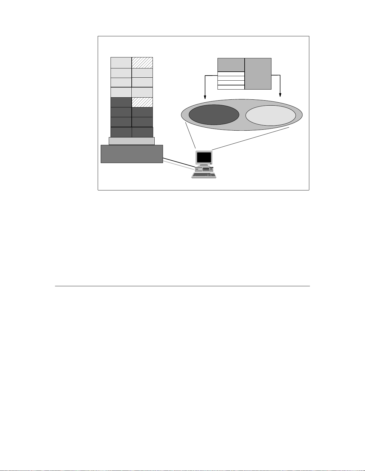
Partition B
Cross-partition com munication
through the SP Switch
IP Switch
Control
Board
SP Switch
SP Switch
4-port FDDI
Crosspoint
Switch
GRF 1600/400
Partition A
Switch
Frame
Figure 26. Partitioning
RS232
Cable
Ethernet
Cable
Partition A
SDR
CWS
PSSP 2.4
Partition B
Normally, RS/6000 SP nodes in different partitions cannot communicate with
each other through the SP Switch. The GRF plays a unique role here by
allowing RS/6000 SP nodes to communicate across partitions, when each
partition contains at least one SP Switch router adapter, and these adapters
are interconnected by TCP/IP.
The requirements for partitioning are the same as those for coexistence, with
the addition of having at least one free SP Switch port per partition, to
connect to the SP Switch router adapter.
2.5 Planning for the GRF
Before acquiring any model of the SP Switch Router, ensure that there are
SP Switch ports available in the designated partition, and that the switch used
in the RS/6000 SP is the 8-port or 16-port SP Switch.
Router Node 63
Page 82

Next, ensure that the following parameters are defined:
ParametersDescriptions
GRF IP addressT he IP address for the GRF adm inistrative Ethernet.
GRF netmaskThe Netmask for the GRF administrative Ethernet.
GRF Default routeThe default route of the GRF.
SNMP communi ty name This attribute describes the SNMP community
name that the SP Extension Node SNMP Manager
and the GRF’s SNMP Agent will send in the
corresponding field of the SNMP messages. This
value must match the value specified for the s ame
attribute of the corresponding dependent node
definition on the SP system. If left blank, a default
name found in the SP Switch Router Adapter
documentation is used.
CWS IP addressThe Control Workstation’s IP address. When a GRF
contains multiple SP Switch router adapters that
are managed by different SNMP managers on
different RS/6000 SP CWS, each of the Control
Workstation IP addresses should be defined along
with a different community name for each Control
Workstation.
DNSThe DNS server and domain name, if used.
SP Extensio n N o de S NMP
Manager port #The SNMP port number used by the SP Extension Node
SNMP Manager to communicate with the SNMP
agent on the GRF.
This port number is 162 when the SP Extension
Node SNMP Manager is the only SNMP m anager
on the Control Workstation. Otherwise, another
port number not used in the /etc/services of the
Control Workstation is chosen.
64 IBM 9077 SP Switch Router: Get Connec ted to the SP S witch
Page 83

2.6 Planning for the D ependent Node
Next, for each dependent node on the RS/6000 SP, define the following:
ParametersDescriptions
Node #A us er-supplied dependent node number representing the node
position of an unused SP Switch port to be used
by the SP Switch Router Adapter.
Slot #The slot number on which the SP Switch Router Adapter is located in
the GRF.
GRF hostname The hostname for the GRF administrative Ethernet. A long
hostname is recommended if the domain name
service (DNS) is used in the network. This
represents both the Administrative and SNMP
agent hostname of the dependent node.
SNMP communi ty name This attribute describes the SNMP community
name that the SP Extension Node SNMP Manager
and the GRF’s SNMP Agent will send in the
corresponding field of the SNMP messages. This
value must match the value specified in the
/etc/snmpd.conf file on the GRF. If left blank, a
default name found in the SP Switch Router
Adapter documentation is used.
SP Extensio n N o de S NMP
Manager port #The SNMP port number used by the SP Extension Node
SNMP Manager to communicate with the SNMP
agent on the GRF.
This port number is 162 when the SP Extension
Node SNMP Manager is the only SNMP manager
on the Control Workstation. Otherwise, another
port number not used in the /etc/services of the
Control Workstation is chosen.
Then, for the dependent node adapter, define these parameters:
ParameterDescriptions
IP addressThe IP address of this adapter.
NetmaskThe netmask of this adapter. Use the same format as that for
standard RS/6000 SP nodes.
Router Node 65
Page 84

2.7 Conclusion
The SP Switch Router 9077-04S has an aggregate bandwidth of 800 MB/s.
An SP wide node by contrast is capable of no more than about 65 M B/s of
sustained throughput. A wide node’s CPU hits a wall at about 5000
packets/second, whereas the 9077 is capable of an aggregate of 2.8 million
packets/second. All this is achieved in part because of the non-blocking
crosspoint switch with four 100 MB/s, full duplex connection points. This
enables multiple paths to operate at full speed simultaneously.
Unlike the SP nodes, the SP Switch Router is designed with high availability
in mind. It provides balanced, fully redundant power supplies that can be hot
swapped in case of failure. It provides the abilit y f or r edundant paths to an SP
Switch to be configured on a single 9077; with dynamic routing protocols, a
second 9077 can be used to provide a backup path in cas e of system failure
of the primary router. In either case, each media card is hot swappable and
autoconfigured after the initial install has been completed.
With its high port count on interfaces such as FDDI and Ethernet and its
highly scalable performance, the SP Switch Router provides a very cost
effective solution. With each media card you get a nearly linear scaling of
performance with very little cost increase. An SP node by comparison runs
out of CPU cycles and/or slots very quickly requiring the purchase of another
entire node.
Since the 9077 (or rather the Ascend GRF) was originally designed for ISP’s,
it has a full set of protocols, including dynamic routing protocols such as
OSPF, BGP4 and RIPv2. It also has the memory required to hold up to
150,000 routes and the speed to access a table of this size without
performance degradation. Support for media types not supported by the SP
nodes also enables the SP to now be connected into networks that will be
important for its future. These include support for HSSI and Sonet, which are
important for the SP’s ever-growing role as a Web server or online
transaction manager.
66 IBM 9077 SP Switch Router: Get Connec ted to the SP S witch
Page 85

Part 2. Scenari os
This part presents some sample configurations of an RS/6000 SP system
with an SP Switch Router. It is beyond the scope of this book to represent all
possible applications of an SP Switch Router. Nevertheless, the basic
configurations shown are building blocks for more complex networking
topologies that include the SP Switch Router and may inspire more complex
configurations.
All following sample scenarios were carefully chosen to match frequently
occurring customer situations. They can be easily configured and modified to
apply to customers’ needs. All configurations described were tested in our
laboratory with the available hardware and software. We used two RS/6000
SPs, each consisting of a control workstation (CWS) and one frame with an
SP Switch and several nodes (see Figure 27). All nodes and the CWS were
installed with AIX 4.3.1 and PSSP 2.4. Additionally, a GRF1600 and a
GRF400 running Ascend Embedded/OS V1.4.6.4. were used. Only static
routing was applied in our tests. For using and configuring gated on an SP
Switch Router refer to
GRF Reference Guide 1.4,
configuration information, refer to Appendix A, “Laboratory Hardware and
Software Configuration” on page 233, and the scenario sections.
SP 21 SP 2
GRF 400
GA22-7367. For detailed
GRF 1600
CWS 21
Figure 27. The Laboratory Hardware Ins tallation
CWS 2
But first let us get physical and see how the SP Switch Router media cards
are configured.
© Copyright IBM Corp. 1998 67
Page 86

68 IBM 9077 SP Switch Router: Get Connec ted to the SP S witch
Page 87

Chapter 3. Install ation and Con figuration
The SP Switch Router functions as an IP router to provide high-speed data
communication links between SP processor nodes and external networks or
hosts. The SP Switch Router Adapter media card connects to the SP Switch
board in an SP system as shown in Figure 28.
Administrative network =
Ethernet hub or bridge
SP Switch Router
Switch
to/from other networks and hosts
Figure 28. Connecting th e GRF to the SP Switch and the CWS
Control
board
SP Switch
Router Adapter
media card
SP Control Workstation
Processor
node
Processor
node
SP Switch
Primary node
for SP Switch
The SP Switch Router Adapter car d al so t ransmits data t o/from other types of
media cards acro ss the SP S wi tch Rout er’s i nt ernal switch core. Thes e medi a
cards include HIPPI, HSSI, FDDI, ATM OC-3c, AT M OC-12c, 100Base-T
(Fast Ethernet), and other SP Switch Router Adapter cards. The SP system
manages the SP Switch Router Adapter c ard as a dependent node, under the
control of the SP SNMP Manager running on the SP Control Workstation and
the Primary node of the SP Switch. To learn more about dependent nodes,
see Chapter 1, “Dependent Node” on page 3. Once powered on and started
up, the SP Switch Router can be configured and managed remotely, either via
a site’s administrative network, or using Telnet from the CWS.
Information about procedures performed from the SP CWS are found in the
"Managing Extension Nodes" chapter in
Version 2 Release 4
© Copyright IBM Corp. 1998 69
, GC 23-3897.
RS/6000 SP: Administration Guide
Page 88

The intent of this chapter is to provide, or refer you to, the necessary
information to enable you to attach an SP Switch Router to an IBM SP
system. Coverage is provided as follows:
• Information to configure the SP Switch Router Adapter card as required
for SP Switch Router functionality is complete in this chapter.
• Information to physically connect the two independent systems across
cables is complete in this chapter.
• Information to start up, configure, and begin operations on the SP Switch
Router is contained in
• Information to configure the SP Switch Router Adapter card as required
for SP system functionality is only partially described in this chapter.
Detailed information is contained in the "Managing Extension Nodes"
chapter in
3897.
3.1 Initial Configura tion
When a new, unconfigured GRF is powered on an initial configuration script
runs automatically. You will be asked a series of questions about the
configuration, as shown in the following screen.
GRF 400/1600 Getting Started
1.4, GA22-7368.
RS/6000 SP: Administration Guide Version 2 Release 4,
GC23-
Welcome to Ascen d Embedd ed/OS sys tem confi gurati on..
Host na me for th is machi ne ?
Do you wish to c onfigure the main tenance E therne t interf ace ?
Which i nterface type ? ( TP BNC AU I)
IP addr ess of th is machi ne ?
Netmask for this network ?
IP addr ess of ro uter (‘n one’ for no defaul t rout e)?
Do you wish to g o throug h the que stions ag ain ?
Which r egion is this mac hine loca ted in ?
Which t ime zone ?
Next you are prompted to change the local password for root.Changing the
root password is the end of the configuration script. If you need to change
these parameters later , run the config_nets tat script again. More detai ls about
the initial configuration are in
If you log onto the GRF, a
super> prompt appears. This indicates that you are
GRF Configuration Guide 1.4
, GA22-7366.
in the command-line interface (CLI). This CLI is different compared to other
Instal lation and Config uration 70
Page 89

UNIX systems. On most of the UNIX systems you are working on the shell
layer after you logged onto the system.
Many system management and configuration commands are now available.
Enter a question mark (?) to retrieve a list of CLI commands. To edit
configuration fil es, you must be i n t he UNIX shell. The
sh command opens the
UNIX shell you use to modify configurations. The fol l owi ng screen shows how
to do th i s .
August 22 14:18: 31 grf16 kernel: ge027: GR F Ethe rnet, GR IT addres s 0:2:7
super>
super>l s
super>n o profile was spe cified
super>s h
Copyrig ht 1992, 1993, 19 94, 1995, 1996 Ber keley Software Design, Inc.
Copyrig ht (c) 19 80, 1983 , 1986, 1 988, 1990 , 1991 , 1993, 1994
The Rege nts of t he Univer sity of C alifor nia. All rights r esevered.
Ascend Embedded/ OS GR TA 1.4.6 Ker nel #1 (n it): F ri Jan 3 0 13:08:0 3 CST 199 8
Ascend E mbedded/O S 1.4.6
Copyrig ht 1992,1 993,1994 ,1995,199 6,1997,19 98 Asc end Comm unication s, Inc.
IMPORTA NT: By us e this s oftware y ou become subje ct to th e terms a nd
conditi ons of th e licens e agreeme nt on fil e /etc /license and any other
License agreemen ts previ ously pro vided to you bt Ascend Communica tions.
#ls
.chsrc .klogin . login .p rofile
#
We found it more convenient to work directly at the shell layer. Therefore, we
modified the .profile
and commented the appropriate part that starts the CLI.
For more details, see Appendix B.1, “/root/.profile” on page 261.
3.2 Pre-Installation Assumptions
We assume the following:
• The RS/6000 SP Switch Router is powered on and has a VT-100 or
administrative Ethernet network connected to its control board.
Figure 29 on page 73 and Figure 30 on page 74 illus trate c orrec t
connections and proper setup.
• The SP Switch Router’s basic system parameters, such as the IP address
and host name, were configured during the first power-on configuration
script. You use t he terminal or network to log in to the SP S witch Router
Instal lation and Config uration 71
Page 90

system and enter these basic configuration parameters. Procedures for
starting and setting up the SP Switch Router are found in
Getting Started V.14,
GA22-7368.
GRF 400/1600
Ignore the prompts for network logging, since we will configure logging to
a PCMCIA device; just press Enter
when asked to enter the remote
logging host name or its IP address.
• Remote Telnet access is working. To enable it, you have to edit the /etc/
ttys file on the SP Switch Router and modify the appropriate entries, as
follows:
#name getty ty pe status c omments
ttyp0 none ne twork secure
ttyp1 none ne twork secure
ttyp2 none ne twork
ttyp3 none ne twork
Adding
secure to a tt ypX stanza opens it for Telnet, so in this example, only
two Telnet sessions at a time were allowed.
Use the following command to connect to the SP Switch Router:
xterm -sb -geometr y 80x65 -e te lnet <hostname of S P Switch Rout er>
This gives you a large window with a scroll bar at the left, so that you may
retrieve information easier. See Appendix B.1, “/root/.profile” on page 261
for a modified .profile for the root user.
Hint:
If you just use -e telnet and give the hostname at the telnet>
prompt, the window will survive reboots of the GRF.
Instal lation and Config uration 72
Page 91

Standard Switch Cable of 10m
Other Switch Cables
5 m (f/c 9305)
Ethernet
Cable
RS232
Cable
Figure 29. Connecting th e GRF to the Fram e
• You are ready to configure media cards. Procedures to configure media
cards are in this redbook; complete information is in the
Configuration Guide 1.4,
CWS
PSSP 2.4
GA22-7367.
15 m (f/c 9315)
20 m (f/c 9320)
10BaseT
SP Switch Cable
Grounding Cable
IP Switch
Control
Board
SP Switch
GRF
Crosspoint
Switch
10 m (f/c 9310)
Instal lation and Config uration 73
Page 92
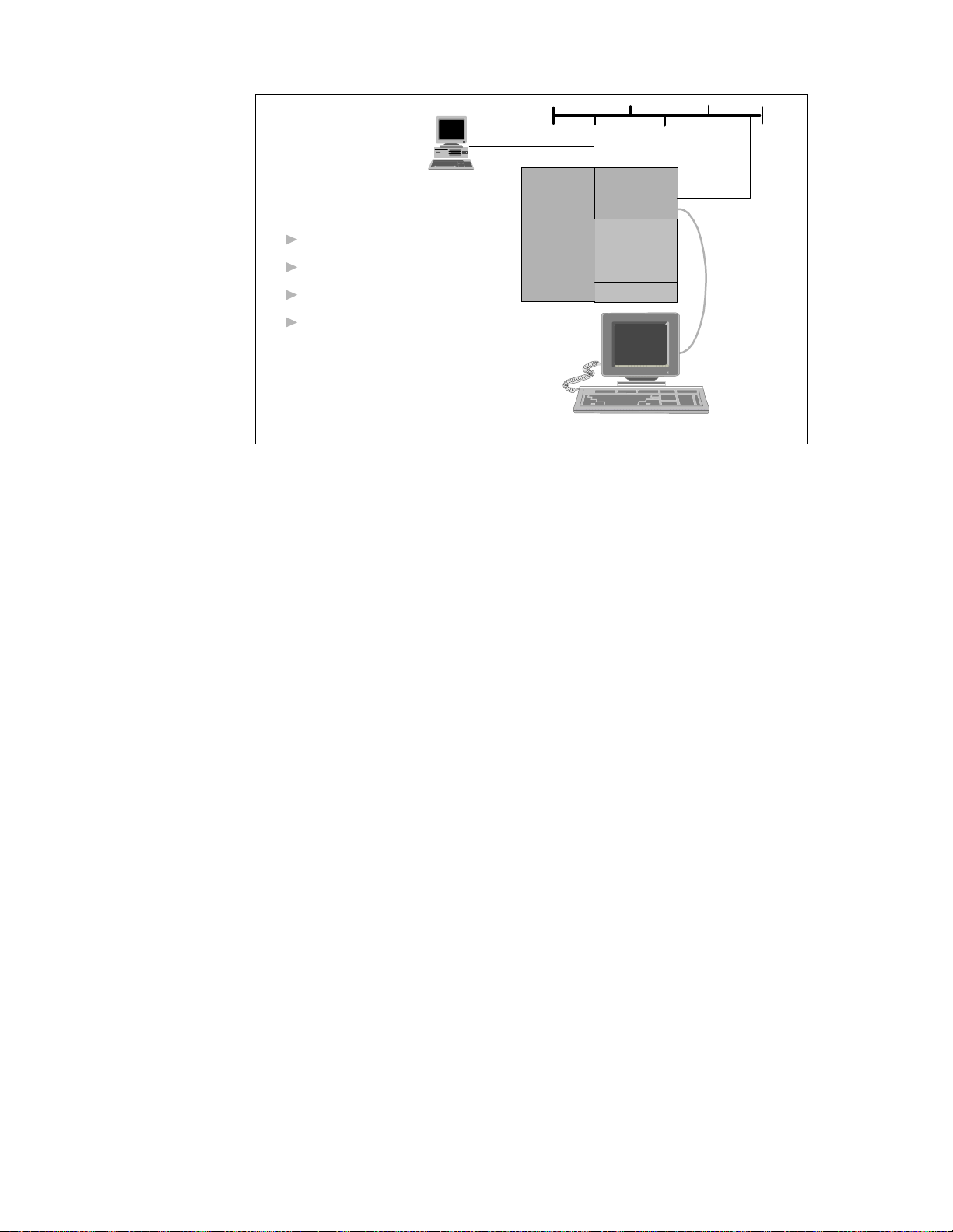
Admin Ethernet
(de0)
RS232
(Null
Modem
Cable)
Terminal Settings
9600 baud
No parity
Eight data bits
cws
GRF 400
Crosspoint
Switch
IP Switch
Control
Board
SP Switch
One stop bit
VT100
terminal
GRF Console (optional)
Figure 30. Connecting th e GRF Console
• The IBM SP system is up and operating.
• The SP system administrator has given you one of these pieces of
information:
• The node number assigned to each SP Switch Router Adapter card to
be attached to an SP Switch port
• The port location on each SP Switch reserved for specific SP Switch
Router Adapter cards
3.2.1 Order of Inform ation
Here is the sequence of steps you have to complete:
1. An installation overview of tasks involving the SP Switch Router, the SP
Switch Router Adapter card, and the SP system
2. The configuration procedure for the PCMCIA 520 MB disk, which also
initiates system logging
3. A description of which cables to attach between the SP Switch Router and
the SP control workstation, and between the SP Switch Router Adapter
card and the SP Switch
Instal lation and Config uration 74
Page 93

4. Methods to determine node number and SP Switch port for an SP Switch
Router Adapter card
5. A step-by-step configuration of an SP Switch Router Adapter card
6. A list of ways to verify that the SP Switch Router Adapter card is correctly
installed in the SP Switch Router
7. A description of what needs to oc cur to bring the card online to the S P
system
3.3 Installing an SP Switch Router Adapter Card
This section contains the procedure for physical installation and minimal
configuration of the SP Switch Router Adapter card for use as an SP
dependent node. This includes cabling the GRF to the SP CWS and the
appropriate SP Switch port.
Note
: There needs to be a network path between Ethernet twisted-pair
interface on the SP Switch Router control board and the SP control
workstation. This is most easily done through an Ethernet hub (or bridge to
the 10BaseT SP LAN). However, it can also be done through a connection to
a network external to the SP.
3.3.1 Installation Overview
IBM support personnel who install the SP Switch Router (9077) perform the
physical installation and minimal configurat ion described below with help fr om
the customer’s system administrator. The system administrator must
complete the following basic configuration steps:
1. Locate all the components of the SP Switch Router ch i p group.
2. Perform the complete physical installation of the SP Switch Router unit as
described in the "Power On and Initial Configuration" chapter of
1600 Getting Started 1. 4,
power on configuration script" runs at system boot, the required
configuration information is provided by or entered by the customer. This
information includes the SP Switch Router unit IP address and hostname.
As stated before, ignore script references to network or syslog logging.
3. Perform the procedure to configure the PCMCIA disk. The procedure is
included in Section 3.3.2, “Installing the PCMCIA Spinning Disk” on page
76.
GA22-7368. Make sure t hat when the "First-time
Instal lation and Config uration 75
GRF 400/
Page 94

4. Route the Ethernet twisted-pair cable between the SP Switch Router unit
and the Ethernet hub, then connect the cable to the SP Switch Router
control board and the Ethernet hub.
5. Verify that the SP CWS has a connection to this same Ethernet hub. If the
SP CWS Ethernet adapter is configured by the system administrator, then
ping test from the SP CWS to the configured SP Switch Router Ethernet
a
address should be done to test Ethernet connectivity.
Physical installation and minimal configuration are complete at this point.
Review Section 3.4, “Attaching SP Switch Router Cables” on page 79 before
connecting the SP Switch Router Adapter card cables to the SP Switch ports
specified for this configuration.
3.3.2 Installing the PCMCIA Sp inning Disk
Your system is shipped with a PCMCIA disk that is required to collect the
system log files. This disk can hold up to 520 MB of dat a regarding your
model of the SP Switch Router.
You can install the disk any time after the SP Switch Router is powered on
and running. Logging is not enabled until you install the disk and complete
this configuration procedure. Logged messages might be very helpful while
you are configuring media cards. The configuration is done only once to set
up local logs and dumps, and is not affected by software updates or system
reboots. System logs include: gritd.packets, grinchd.log, gr.console,
gr.conferrs, gr.boot and mib2d.log.
The procedure formats and initializes an external flash (/dev/wdXa), where
the X is normally a 1, denoting the number of the device. You get the actual
number from the
mountf command. We have /dev/wd3a in our example and
this value will be used for the rest of this chapter. The procedure then mounts
the flash temporarily on /mnt and creates subdirectories, symbolic links and a
permanent site file for storing the symbolic links.
Proceed as follows:
1. Insert the PCMCIA disk into slot A on the S P Switch Router control board
(the width of the disk requires it to be installed in slot A).
2. Log in as root to the SP S witch Router, start the UNIX shell, and execute
the following commands from the shell:
Instal lation and Config uration 76
Page 95

prompt> sh
#
# cd /
# iflas h -A
May 29 15:54:18 grf16 ke rnel: wd2 : no disk label
# mount f -A -w - m /mnt
Device /dev/wd3a mounted on /mnt
# mkdir /mnt/cra sh
# mkdir /mnt/por tcards
# cd /v ar
# mv cr ash crash .orig
# mv po rtcards p ortcards .orig
# ln -s /var/log /portcar ds /var/p ortcards
# ln -s /var/log /crash / var/crash
# grsit e --perm portcard s crash
Device /dev/wd0a mounted on /flas h.
Device /dev/wd0a unmount ed.
#
# cd /v ar/log
# pax - rw -pe -v . /mnt
/mnt/.
/mnt/./ cron
/mnt/./ daemon.lo g
/mnt/./ lastlog
/mnt/./ maillog
/mnt/./ messages
/mnt/./ secure
/mnt/./ wtmp
/mnt/./ grclean.l og
/mnt/./ mibmgrd.l og
/mnt/./ cli.log
# umoun tf -A
Device /dev/wd3a unmount ed.
#
3. Edit the file /etc/rc.boot and see if the line
mount /dev/wd3a / var/log is
present; if not, add this line at the end of the file.
4. Edit the file /etc/fstab and add this line as shown in the following excerpt:
/dev/wd3a /var/log ufs rw 0 2 # PC MCIA slot A
## Each line is of the f orm:
## dev ice mount _point t ype flags dump fsc k_pass
/dev/rd 0a / ufs rw 0 0
/dev/wd 3a /var/l og ufs r w 0 2 # P CMCIA slo t A
Instal lation and Config uration 77
Page 96

5. Edit the file /etc/syslog.conf
to specify the location where the logs will be
kept. Uncomment the local log configuration lines in the “Log messages to
section by removing #disk# from each line, and specify /var/log as
Disk”
the directory for each log. The entries should now look like the following:
*.err;* .notice;ker n.debug;lpr, auth.info;ma il.crit /var/l og/messag es
cron.in fo /var/log/cr on
local0. info /var /log/gri td.packet s
local1. info /var /log/gr. console
local2. * /var/lo g/gr.boo t
local3. * /var/lo g/grinch d.log
local4. * /var/lo g/gr.con ferrs
local5. * /var/lo g/mib2d. log
6. Check that /etc/grclean.conf and /etc/grclean.logs.conf have entries
pointing to files in /var/log.
The /etc/grclean.conf file entries should look like the following:
####### ######### ######## ######### ######### ###### ######## ######### ##
# port card dump files.
####### ######### ######## ######### ######### ###### ######## ######### ##
hold=4
size=1
remove= y
local=y
logfile =/var/por tcards/g rdump.*
####### ######### ######## ######### ######### ###### ######## ######### ##
# clean up our ow n log fi le, if ne cessary.
####### ######### ######## ######### ######### ###### ######## ######### ##
DEFAULT S
hold=2
local=y
size=10 000
logfile =/var/log /grclean .log
The /etc/grclean.logs.conf file entries should look like the following:
Instal lation and Config uration 78
Page 97

******* *********** ********* ********* ************ ******** ********* ******
* Log f iles that used to be archi ved by th e /etc /{daily| weekly|mo nthly}
* scrip ts.
******* ********* ******** ********* ********* ****** ******** ********* ******
size=15 0000
logfile =/var/log /gr.cons ole
size=11 000
logfile =/var/log /gr.boot
7. Save all c hanges and reboot:
# grwrite -v
# reboot
8. After the SP Switch Router is up and running again, use csconfig -a to
verify that the PCMCIA interface is available and the PCMCIA disk are up.
For a quick test, run
grconslog -vf. If the setup is correct, grc onslog will
not complain about a missing /var/log/gr.console file, but instead will show
all entries and stay up running, giving updates of new entries to the file
onto the screen. To s top
grconslog, use Ctrl+C.
3.4 Attaching SP Switch Router Cables
Three types of cables must be attached:
• The administrative Ethernet LAN cable
• The SP Switch Router Adapter card to SP Switch cable(s)
• The ground strap to the SP frame
3.4.1 Ethernet Cable
Route the Ethernet twisted-pair cable between the SP Switch Router unit and
the Ethernet hub, then connect the cable to the SP Switch Router control
board and to the Ethernet hub. See Figure 31 on page 80 on how this might
be accomplished.
Instal lation and Config uration 79
Page 98

Hub
SP Switch Router
Admini strati ve Ether net network
Control board
Figure 31. SP System Admi nistrative Ethernet Connectio ns
3.4.2 SP Switch Cable
The SP Switch Router Adapter card provides one full-duplex attachment and
requires a specific cable with 50-pin connector ends, obtainable from IBM.
The cable has a unique signal wiring map, and is not replaceable by a 50-pin
HSSI cable, for ex ample. SP Switch Router Adapter car d cables are available
in 10- and 20-meter lengths (32 or 65 feet). Excess cable lengths should be
bound in a figure-eight pattern. Do not wind excess cable into circular coils.
Each connector end has 50 fragile pins. Pins can become bent when making
the connection to the media card if alignment is wrong. If an SP Switch
Router Adapter card link does not work after cabling, check both ends of the
cable for bent pins. When not connected, keep the plastic caps on the ends.
3.4.3 Procedure for Connecting Cards to the SP Switch
This procedure connects the SP Switch Router Adapter card(s) to the SP
Switch. Before the SP Switch Router unit can begin full operation, all other
router media cards must be configured with appropriate customer
configuration information.
SP Control Workstation
Make sure you have labeled the SP Switch cable to show which m edia card
and SP Switch port it will be c onnected t o. Keep i n mind that for any work
done on the SP Switch you should have shut down and powered off the SP
System and also turned off the central power supply switch at the left front
edge of the SP.
Execute the following steps to make the connections:
1. If there are any terminators on the media card or the switch a ss embly
where you need to attach the switch cable, remove them now.
Instal lation and Config uration 80
Page 99

2. Using appropriate frame entry and exit holes for cable management, route
the SP Switch cable between the SP Switch Router unit and the S P
Switch.
3. Connect the S P Switch cable to both the m edia card and t he c orrect SP
Switch port, as follows:
• Connection to media card
The EMI shielding fitted inside the connector end can make insertion
difficult, so be sure to insert the connector end as perpendicular as
possible. (Pins can be damaged when the connector is inserted at too
much of an angle.) Seat the connector firmly so the spring clips engage.
• Connection to SP Switch port
The cable ends should click onto the connectors. Determining the correct
Switch port is described in Section 3.5.1, “Determining the Switch
Connection for a Dependent Node” on page 82.
4. Make sure both ends of the cable are firmly seated by pulling on them
lightly.
At this point, the SP Switch Router Adapter card configuration information
must be entered on the SP CWS to enable the PSSP c ode and SP S witch to
recognize the adapter. These tasks are discussed in Section 3.5,
“Configuration Required on the SP System” on page 81.
3.5 Configuration R equired on the S P System
This section describes the SP Switch Router-related configuration
information that should be defined by the SP administrator and then entered
from the SP CWS before the SP Switch Router Adapter card is configured.
The SP Switch Router-related configuration information includes the
following:
• The SP Switch Router Ethernet IP address
• The SP Switch Router Ethernet hostname (that is, the SP Switch Router’s
administrative Ethernet hostname)
• Unique node numbers for SP Switch Router Adapter cards
The SP Switch Router Adapter card configuration information enables the
PSSP code and the SP Switch to recognize and communicate with this card.
Instal lation and Config uration 81
Page 100

3.5.1 Determ ining the Switch C onnection fo r a Dependent Nod e
The SP Switch Router Adapter connection replaces an SP node connection
to the SP Switch. Each SP Switch Router Adapter media card is referred to
as a dependent node, and is assigned a node number that corresponds to its
specific connection on the SP Switch.
The node number is determined by the SP system administrator based on an
understanding of how node numbers are assigned in the SP System and the
rules for choosing a valid, unused SP Switch port.
See Figure 32 on page 83 for a brief overview of how Switch port numbers
are assigned and how to look for the best suited port number for the actual
scenario.
Note:
Look out for the change in numbering regarding Frame n+2 and
Frame n+3!
See Figure 33 on page 84 on how node numbers are assigned independent
of whether the frame is fully populated.
If proper planning has been done to assign the node number, the system
administrator knows which SP frame, Switch board, and node slot
corresponds to a dependent node. Given this information, you can determine
which jack on the Switch board should be used by consulting the Switch
Cable Charts for the SP Switch in
Volume 1, Installation and Customer Engineer Operations
RS/6000 SP: Maintenance Information,
, GC23-3903.
Do not attempt to connect an SP Switch Router Adapter to the SP Switch until
proper planning has been done to assign the node number.
Once the node number is assigned, the SP system administrator can define
the corresponding dependent node using SMIT as described in the
"Managing Extension Nodes" section of
Version 2 Release 4,
GC23-3897.
RS/6000 SP: Administration Guide
After defining new dependent nodes on the SP, t he administrator should use
Eannotator command to annotate the SP Switch topology file. With the file
the
annotated, even if the administrator is not sure of the frame, switch board, or
node slot for the dependent node, you can determine the corresponding
switch connection with the procedure described in Section 3.5.2, “Procedure
to Get the Jack Number” on page 84.
Instal lation and Config uration 82
 Loading...