

Page 1

Power Systems
Site and hardware planning
IBM
Page 2

Note
Before using this information and the product it supports, read the information in “Safety notices” on
page v, “Notices” on page 139, the IBM Systems Safety Notices manual, G229-9054, and the IBM
Environmental Notices and User Guide, Z125–5823.
This edition applies to IBM® Power Systems servers that contain the POWER9™ processor and to all associated models.
©
Copyright International Business Machines Corporation 2018, 2019.
US Government Users Restricted Rights – Use, duplication or disclosure restricted by GSA ADP Schedule Contract with
IBM Corp.
Page 3

Contents
Safety notices........................................................................................................v
Site and hardware physical planning overview....................................................... 1
Planning activities................................................................................................. 3
Planning task checklist................................................................................................................................ 3
General considerations................................................................................................................................3
Site preparation and physical planning guidelines..................................................................................... 4
Site and hardware planning................................................................................... 7
Hardware specication sheets.................................................................................................................... 7
Server specications.............................................................................................................................. 7
Expansion unit and migration tower specications............................................................................ 18
Rack specications...............................................................................................................................22
Hardware Management Console specications..................................................................................64
Rack switch specications...................................................................................................................67
Rack installation specications for racks that are not purchased from IBM..................................... 70
Planning for power.....................................................................................................................................78
Determining your power requirements............................................................................................... 78
Plugs and receptacles.......................................................................................................................... 80
Modication of IBM-provided power cords.........................................................................................95
Uninterruptible power supply.............................................................................................................. 96
Power distribution unit and power cord options for 7014, 7953, and 7965 racks............................97
Calculating the power load for 7188 or 9188 power distribution units...........................................105
Planning for cables.................................................................................................................................. 107
Cable management............................................................................................................................ 107
Planning for serial-attached SCSI cables..........................................................................................111
Notices..............................................................................................................139
Accessibility features for IBM Power Systems servers..........................................................................140
Privacy policy considerations .................................................................................................................141
Trademarks..............................................................................................................................................141
Electronic emission notices.....................................................................................................................141
Class A Notices...................................................................................................................................142
Class B Notices...................................................................................................................................145
Terms and conditions.............................................................................................................................. 147
iii
Page 4

iv
Page 5

Safety notices
Safety notices may be printed throughout this guide:
• DANGER notices call attention to a situation that is potentially lethal or extremely hazardous to people.
• CAUTION notices call attention to a situation that is potentially hazardous to people because of some
existing condition.
• Attention notices call attention to the possibility of damage to a program, device, system, or data.
World Trade safety information
Several countries require the safety information contained in product publications to be presented in their
national languages. If this requirement applies to your country, safety information documentation is
included in the publications package (such as in printed documentation, on DVD, or as part of the product)
shipped with the product. The documentation contains the safety information in your national language
with references to the U.S. English source. Before using a U.S. English publication to install, operate, or
service this product, you must rst become familiar with the related safety information documentation.
You should also refer to the safety information documentation any time you do not clearly understand any
safety information in the U.S. English publications.
Replacement or additional copies of safety information documentation can be obtained by calling the IBM
Hotline at 1-800-300-8751.
German safety information
Das Produkt ist nicht für den Einsatz an Bildschirmarbeitsplätzen im Sinne § 2 der
Bildschirmarbeitsverordnung geeignet.
Laser safety information
IBM servers can use I/O cards or features that are ber-optic based and that utilize lasers or LEDs.
Laser compliance
IBM servers may be installed inside or outside of an IT equipment rack.
DANGER:
Electrical voltage and current from power, telephone, and communication cables are hazardous.
To avoid a shock hazard:
• If IBM supplied the power cord(s), connect power to this unit only with the IBM provided power
cord. Do not use the IBM provided power cord for any other product.
• Do not open or service any power supply assembly.
• Do not connect or disconnect any cables or perform installation, maintenance, or reconguration
of this product during an electrical storm.
• The product might be equipped with multiple power cords. To remove all hazardous voltages,
disconnect all power cords.
– For AC power, disconnect all power cords from their AC power source.
– For racks with a DC power distribution panel (PDP), disconnect the customer’s DC power
• When connecting power to the product ensure all power cables are properly connected.
When working on or around the system, observe the following precautions:
source to the PDP.
– For racks with AC power, connect all power cords to a properly wired and grounded electrical
outlet. Ensure that the outlet supplies proper voltage and phase rotation according to the
system rating plate.
©
Copyright IBM Corp. 2018, 2019 v
Page 6

– For racks with a DC power distribution panel (PDP), connect the customer’s DC power source
to the PDP. Ensure that the proper polarity is used when attaching the DC power and DC power
return wiring.
• Connect any equipment that will be attached to this product to properly wired outlets.
• When possible, use one hand only to connect or disconnect signal cables.
• Never turn on any equipment when there is evidence of re, water, or structural damage.
• Do not attempt to switch on power to the machine until all possible unsafe conditions are
corrected.
• Assume that an electrical safety hazard is present. Perform all continuity, grounding, and power
checks specied during the subsystem installation procedures to ensure that the machine meets
safety requirements.
• Do not continue with the inspection if any unsafe conditions are present.
• Before you open the device covers, unless instructed otherwise in the installation and
conguration procedures: Disconnect the attached AC power cords, turn off the applicable
circuit breakers located in the rack power distribution panel (PDP), and disconnect any
telecommunications systems, networks, and modems.
DANGER:
• Connect and disconnect cables as described in the following procedures when installing,
moving, or opening covers on this product or attached devices.
To Disconnect:
1. Turn off everything (unless instructed otherwise).
2. For AC power, remove the power cords from the outlets.
3. For racks with a DC power distribution panel (PDP), turn off the circuit breakers located in the
PDP and remove the power from the Customer's DC power source.
4. Remove the signal cables from the connectors.
5. Remove all cables from the devices.
To Connect:
1. Turn off everything (unless instructed otherwise).
2. Attach all cables to the devices.
3. Attach the signal cables to the connectors.
4. For AC power, attach the power cords to the outlets.
5. For racks with a DC power distribution panel (PDP), restore the power from the Customer's
DC power source and turn on the circuit breakers located in the PDP.
6. Turn on the devices.
Sharp edges, corners and joints may be present in and around the system. Use care when
handling equipment to avoid cuts, scrapes and pinching. (D005)
(R001 part 1 of 2):
DANGER:
• Heavy equipment–personal injury or equipment damage might result if mishandled.
• Always lower the leveling pads on the rack cabinet.
• Always install stabilizer brackets on the rack cabinet unless the earthquake option is to be
installed.
• To avoid hazardous conditions due to uneven mechanical loading, always install the heaviest
devices in the bottom of the rack cabinet. Always install servers and optional devices starting
from the bottom of the rack cabinet.
Observe the following precautions when working on or around your IT rack system:
vi Power Systems: Site and hardware planning
Page 7
• Rack-mounted devices are not to be used as shelves or work spaces. Do not place objects on top
of rack-mounted devices. In addition, do not lean on rack mounted devices and do not use them
to stabilize your body position (for example, when working from a ladder).
• Each rack cabinet might have more than one power cord.
– For AC powered racks, be sure to disconnect all power cords in the rack cabinet when directed
to disconnect power during servicing.
– For racks with a DC power distribution panel (PDP), turn off the circuit breaker that controls
the power to the system unit(s), or disconnect the customer’s DC power source, when
directed to disconnect power during servicing.
• Connect all devices installed in a rack cabinet to power devices installed in the same rack
cabinet. Do not plug a power cord from a device installed in one rack cabinet into a power device
installed in a different rack cabinet.
• An electrical outlet that is not correctly wired could place hazardous voltage on the metal parts
of the system or the devices that attach to the system. It is the responsibility of the customer to
ensure that the outlet is correctly wired and grounded to prevent an electrical shock. (R001 part
1 of 2)
(R001 part 2 of 2):
CAUTION:
• Do not install a unit in a rack where the internal rack ambient temperatures will exceed the
manufacturer's recommended ambient temperature for all your rack-mounted devices.
• Do not install a unit in a rack where the air flow is compromised. Ensure that air flow is not
blocked or reduced on any side, front, or back of a unit used for air flow through the unit.
• Consideration should be given to the connection of the equipment to the supply circuit so that
overloading of the circuits does not compromise the supply wiring or overcurrent protection. To
provide the correct power connection to a rack, refer to the rating labels located on the
equipment in the rack to determine the total power requirement of the supply circuit.
• (For sliding drawers.) Do not pull out or install any drawer or feature if the rack stabilizer
brackets are not attached to the rack or if the rack is not bolted to the floor. Do not pull out more
than one drawer at a time. The rack might become unstable if you pull out more than one drawer
at a time.
• (For xed drawers.) This drawer is a xed drawer and must not be moved for servicing unless
specied by the manufacturer. Attempting to move the drawer partially or completely out of the
rack might cause the rack to become unstable or cause the drawer to fall out of the rack. (R001
part 2 of 2)
CAUTION:
stability during relocation. Follow these general guidelines whenever you relocate a populated
rack cabinet within a room or building.
• Reduce the weight of the rack cabinet by removing equipment starting at the top of the rack
cabinet. When possible, restore the rack cabinet to the conguration of the rack cabinet as you
received it. If this conguration is not known, you must observe the following precautions:
Removing components from the upper positions in the rack cabinet improves rack
Safety notices vii
Page 8
– Remove all devices in the 32U position (compliance ID RACK-001 or 22U (compliance ID
RR001) and above.
– Ensure that the heaviest devices are installed in the bottom of the rack cabinet.
– Ensure that there are little-to-no empty U-levels between devices installed in the rack cabinet
below the 32U (compliance ID RACK-001 or 22U (compliance ID RR001) level, unless the
received conguration specically allowed it.
• If the rack cabinet you are relocating is part of a suite of rack cabinets, detach the rack cabinet
from the suite.
• If the rack cabinet you are relocating was supplied with removable outriggers they must be
reinstalled before the cabinet is relocated.
• Inspect the route that you plan to take to eliminate potential hazards.
• Verify that the route that you choose can support the weight of the loaded rack cabinet. Refer to
the documentation that comes with your rack cabinet for the weight of a loaded rack cabinet.
• Verify that all door openings are at least 760 x 230 mm (30 x 80 in.).
• Ensure that all devices, shelves, drawers, doors, and cables are secure.
• Ensure that the four leveling pads are raised to their highest position.
• Ensure that there is no stabilizer bracket installed on the rack cabinet during movement.
• Do not use a ramp inclined at more than 10 degrees.
• When the rack cabinet is in the new location, complete the following steps:
– Lower the four leveling pads.
– Install stabilizer brackets on the rack cabinet or in an earthquake environment bolt the rack to
the floor.
– If you removed any devices from the rack cabinet, repopulate the rack cabinet from the
lowest position to the highest position.
• If a long-distance relocation is required, restore the rack cabinet to the conguration of the rack
cabinet as you received it. Pack the rack cabinet in the original packaging material, or equivalent.
Also lower the leveling pads to raise the casters off of the pallet and bolt the rack cabinet to the
pallet.
(L001)
(L002)
(R002)
DANGER:
this label attached. Do not open any cover or barrier that contains this label. (L001)
Hazardous voltage, current, or energy levels are present inside any component that has
viii
Power Systems: Site and hardware planning
Page 9
(L003)
or
or
DANGER: Rack-mounted devices are not to be used as shelves or work spaces. Do not place
objects on top of rack-mounted devices. In addition, do not lean on rack-mounted devices and do
not use them to stabilize your body position (for example, when working from a ladder). (L002)
or
or
Safety notices
ix
Page 10

(L007)
DANGER: Multiple power cords. The product might be equipped with multiple AC power cords or
multiple DC power cables. To remove all hazardous voltages, disconnect all power cords and
power cables. (L003)
CAUTION:
(L008)
CAUTION:
All lasers are certied in the U.S. to conform to the requirements of DHHS 21 CFR Subchapter J for class 1
laser products. Outside the U.S., they are certied to be in compliance with IEC 60825 as a class 1 laser
product. Consult the label on each part for laser certication numbers and approval information.
CAUTION:
ROM drive, DVD-RAM drive, or laser module, which are Class 1 laser products. Note the following
information:
• Do not remove the covers. Removing the covers of the laser product could result in exposure to
hazardous laser radiation. There are no serviceable parts inside the device.
• Use of the controls or adjustments or performance of procedures other than those specied
herein might result in hazardous radiation exposure.
A hot surface nearby. (L007)
Hazardous moving parts nearby. (L008)
This product might contain one or more of the following devices: CD-ROM drive, DVD-
(C026)
x Power Systems: Site and hardware planning
Page 11
CAUTION: Data processing environments can contain equipment transmitting on system links
with laser modules that operate at greater than Class 1 power levels. For this reason, never look
into the end of an optical ber cable or open receptacle. Although shining light into one end and
looking into the other end of a disconnected optical ber to verify the continuity of optic bers may
not injure the eye, this procedure is potentially dangerous. Therefore, verifying the continuity of
optical bers by shining light into one end and looking at the other end is not recommended. To
verify continuity of a ber optic cable, use an optical light source and power meter. (C027)
CAUTION: This product contains a Class 1M laser. Do not view directly with optical instruments.
(C028)
CAUTION: Some laser products contain an embedded Class 3A or Class 3B laser diode. Note the
following information:
• Laser radiation when open.
• Do not stare into the beam, do not view directly with optical instruments, and avoid direct
exposure to the beam. (C030)
(C030)
CAUTION: The battery contains lithium. To avoid possible explosion, do not burn or charge the
battery.
Do Not:
• Throw or immerse into water
• Heat to more than 100 degrees C (212 degrees F)
• Repair or disassemble
Exchange only with the IBM-approved part. Recycle or discard the battery as instructed by local
regulations. In the United States, IBM has a process for the collection of this battery. For
information, call 1-800-426-4333. Have the IBM part number for the battery unit available when
you call. (C003)
CAUTION: Regarding IBM provided VENDOR LIFT TOOL:
• Operation of LIFT TOOL by authorized personnel only.
• LIFT TOOL intended for use to assist, lift, install, remove units (load) up into rack elevations. It is
not to be used loaded transporting over major ramps nor as a replacement for such designated
tools like pallet jacks, walkies, fork trucks and such related relocation practices. When this is not
practicable, specially trained persons or services must be used (for instance, riggers or movers).
• Read and completely understand the contents of LIFT TOOL operator's manual before using.
Failure to read, understand, obey safety rules, and follow instructions may result in property
damage and/or personal injury. If there are questions, contact the vendor's service and support.
Local paper manual must remain with machine in provided storage sleeve area. Latest revision
manual available on vendor's web site.
• Test verify stabilizer brake function before each use. Do not over-force moving or rolling the LIFT
TOOL with stabilizer brake engaged.
• Do not raise, lower or slide platform load shelf unless stabilizer (brake pedal jack) is fully
engaged. Keep stabilizer brake engaged when not in use or motion.
• Do not move LIFT TOOL while platform is raised, except for minor positioning.
• Do not exceed rated load capacity. See LOAD CAPACITY CHART regarding maximum loads at
center versus edge of extended platform.
• Only raise load if properly centered on platform. Do not place more than 200 lb (91 kg) on edge
of sliding platform shelf also considering the load's center of mass/gravity (CoG).
• Do not corner load the platforms, tilt riser, angled unit install wedge or other such accessory
options. Secure such platforms -- riser tilt, wedge, etc options to main lift shelf or forks in all four
(4x or all other provisioned mounting) locations with provided hardware only, prior to use. Load
objects are designed to slide on/off smooth platforms without appreciable force, so take care
Safety notices
xi
Page 12

not to push or lean. Keep riser tilt [adjustable angling platform] option flat at all times except for
nal minor angle adjustment when needed.
• Do not stand under overhanging load.
• Do not use on uneven surface, incline or decline (major ramps).
• Do not stack loads.
• Do not operate while under the influence of drugs or alcohol.
• Do not support ladder against LIFT TOOL (unless the specic allowance is provided for one
following qualied procedures for working at elevations with this TOOL).
• Tipping hazard. Do not push or lean against load with raised platform.
• Do not use as a personnel lifting platform or step. No riders.
• Do not stand on any part of lift. Not a step.
• Do not climb on mast.
• Do not operate a damaged or malfunctioning LIFT TOOL machine.
• Crush and pinch point hazard below platform. Only lower load in areas clear of personnel and
obstructions. Keep hands and feet clear during operation.
• No Forks. Never lift or move bare LIFT TOOL MACHINE with pallet truck, jack or fork lift.
• Mast extends higher than platform. Be aware of ceiling height, cable trays, sprinklers, lights, and
other overhead objects.
• Do not leave LIFT TOOL machine unattended with an elevated load.
• Watch and keep hands, ngers, and clothing clear when equipment is in motion.
• Turn Winch with hand power only. If winch handle cannot be cranked easily with one hand, it is
probably over-loaded. Do not continue to turn winch past top or bottom of platform travel.
Excessive unwinding will detach handle and damage cable. Always hold handle when lowering,
unwinding. Always assure self that winch is holding load before releasing winch handle.
• A winch accident could cause serious injury. Not for moving humans. Make certain clicking sound
is heard as the equipment is being raised. Be sure winch is locked in position before releasing
handle. Read instruction page before operating this winch. Never allow winch to unwind freely.
Freewheeling will cause uneven cable wrapping around winch drum, damage cable, and may
cause serious injury.
• This TOOL must be maintained correctly for IBM Service personnel to use it. IBM shall inspect
condition and verify maintenance history before operation. Personnel reserve the right not to use
TOOL if inadequate. (C048)
Power and cabling information for NEBS (Network Equipment-Building System) GR-1089-CORE
The following comments apply to the IBM servers that have been designated as conforming to NEBS
(Network Equipment-Building System) GR-1089-CORE:
The equipment is suitable for installation in the following:
• Network telecommunications facilities
• Locations where the NEC (National Electrical Code) applies
The intrabuilding ports of this equipment are suitable for connection to intrabuilding or unexposed wiring
or cabling only. The intrabuilding ports of this equipment must not be metallically connected to the
interfaces that connect to the OSP (outside plant) or its wiring. These interfaces are designed for use as
intrabuilding interfaces only (Type 2 or Type 4 ports as described in GR-1089-CORE) and require isolation
from the exposed OSP cabling. The addition of primary protectors is not sufcient protection to connect
these interfaces metallically to OSP wiring.
Note: All Ethernet cables must be shielded and grounded at both ends.
The ac-powered system does not require the use of an external surge protection device (SPD).
xii
Power Systems: Site and hardware planning
Page 13

The dc-powered system employs an isolated DC return (DC-I) design. The DC battery return terminal shall
not be connected to the chassis or frame ground.
The dc-powered system is intended to be installed in a common bonding network (CBN) as described in
GR-1089-CORE.
Safety notices xiii
Page 14

xiv Power Systems: Site and hardware planning
Page 15

Site and hardware physical planning overview
Successful installation requires effective planning of your physical and operational environment. You are
the most valuable resource in site planning because you know where and how your system, and the
devices that are attached to it, are used.
Site preparation for the complete system is the responsibility of the customer. The primary task of your
site planner is to ensure that each system is installed so that it can operate and be serviced efciently.
This topic collection provides the basic information that you need to plan for your system installation. It
provides an overview of each planning task and valuable reference information useful throughout the
performance of these tasks. Depending on the complexity of the system that you ordered and your
existing computing resource, you might not need to complete all the steps noted here.
First, with the help of your systems engineer, sales representative, or with the help of those coordinating
your installation, list the hardware for which you need to plan. Use the summary of your order to help you
when you make your list. This list is now your “To Do” list. You can use the Planning task checklist to
assist you.
While you are responsible for planning, vendors, contractors, and your sales representative are also
available to help with any aspect of the planning. For some system units, a customer service
representative installs your system unit and veries correct operation. Some system units are considered
customer-installed. If you are not sure, check with your sales representative.
The physical planning section of this topic collection provides the physical characteristics of many system
units, and associated products. For information on products not included in this topic collection, contact
your sales representative or your IBM reseller.
Before you proceed with planning, ensure that the hardware and software you chose meets your needs.
Your sales representative is available to answer questions.
While this information is for hardware planning, the system memory and disk storage needed are a
function of the software to be used, therefore some things to consider are listed below. Information on
software products is generally in or with the software licensed program itself.
In assessing the adequacy of hardware and software, consider the following guidelines:
• Available disk space and system memory for accommodating software, online documentation, and data
(including future growth needs resulting from extra users, more data, and new applications).
• Compatibility of all devices.
• Compatibility of software packages with each other and with the hardware conguration.
• Adequate redundancy or backup capabilities in hardware and software.
• Software portability to the new system, if necessary.
• Prerequisites and corequisites of chosen software are satised.
• Data to be transferred to the new system.
©
Copyright IBM Corp. 2018, 2019 1
Page 16

2 Power Systems: Site and hardware planning
Page 17
Planning activities
You can use this information to help you plan the physical installation for your server.
Proper planning for your system facilitates a smooth installation and fast system start-up. Sales and
installation planning representatives are also available to help you with installation planning.
As part of your planning activity, you make decisions about where to locate your server and who operates
the system.
Planning task checklist
Use this checklist to document your planning progress.
Working with your sales representative, establish completion dates for each of the tasks. You might want
to review your planning schedule periodically with your sales representative.
Table 1. Planning task checklist
Planning step Person responsible Target date Completion date
Plan your ofce or computer
room layout (physical planning)
Prepare for power cords and
electrical needs
Prepare for cables and cabling
Create or modify
communications networks
Perform building altercations, as
needed
Prepare maintenance, recovery,
and security plans
Develop an education plan
Order supplies
Prepare for system delivery
General considerations
Planning your system requires attention to the numerous details.
When you are determining the placement of your system, look the following considerations:
• Adequate space for the devices.
• Working environment of personnel who are using the devices (their comfort, ability to access the
devices, supplies, and reference materials).
• Adequate space for maintaining and servicing the devices.
• Physical security requirements necessary for the devices.
• Weight of the devices.
• Heat output of the devices.
• Operating temperature requirements of the devices.
©
Copyright IBM Corp. 2018, 2019 3
Page 18

• Humidity requirements of the devices.
• Air flow requirements of the devices.
• Air quality of the location where the devices are used. For example, excess dust can damage your
system.
Note: The system and devices are designed to operate in normal ofce environments. Dirty or other
poor environments might damage the system or the devices. You are responsible for providing the
proper operating environment.
• Altitude limitations of the devices.
• Noise emission levels of the devices.
• Any vibration of equipment near where the devices are placed.
• Paths of power cords.
The following pages contain the information that you need to evaluate these considerations.
Site preparation and physical planning guidelines
These guidelines help you prepare your site for the delivery and installation of your server.
The Site preparation and physical planning topic covers the following information:
Site selection, building and space considerations
• Site selection
• Access
• Static electricity and floor resistance
• Space requirements
• Floor construction and floor loading
• Raised floors
• Conductive contamination
• Computer room layout
Site environment, safety, and security
• Vibration and shock
• Lighting
• Acoustics
• Electromagnetic compatibility
• Computer room location
• Material and data storage protection
• Emergency planning for continuous operations
Electrical power and grounding
• General power information
• Power quality
• Voltage and frequency limits
• Power load
• Power source
• Dual power installations
Air conditioning
• Air conditioning determination
4
Power Systems: Site and hardware planning
Page 19

• General guidelines for data centers
• Temperature and humidity design criteria
• Temperature and humidity recording instruments
• Relocation and temporary storage
• Acclimation
• System air distribution
Planning for the installation of rear door heat exchangers
• Planning for the installation of rear door heat exchangers
• Heat exchanger specications
• Water specications for the secondary cooling loop
• Water delivery specications for secondary loops
• Layout and mechanical installation
• Suggested sources for secondary loop components
Communications
• Planning for communications
Planning activities 5
Page 20

6 Power Systems: Site and hardware planning
Page 21
Site and hardware planning
Learn about the specications that site planners can use to assess the physical site and operational
requirements necessary to prepare your site for a new server. This information includes specications for
servers and expansion units, plugs and receptacles, and cables, and information about power-distribution
units and uninterruptible power supplies.
Hardware specication sheets
Hardware specication sheets provide detailed information for your hardware, including dimensions,
electrical, power, temperature, environment, and service clearances.
Server specications
Server specications provide detailed information for your server, including dimensions, electrical, power,
temperature, environment, and service clearances.
Select the appropriate models to view the specications for your server.
Model 9008-22L, 9009-22A, 9009-41A, 9009-42A, 9223-22H, and 9223-42H server specications
Server specications provide detailed information for your server, including dimensions, electrical, power,
temperature, environment, and service clearances.
Use the following specications to plan for your server.
Table 2. Dimensions for the 9008-22L, 9009-22A, and 9223-22H
Width Depth Height EIA units Weight
482 mm (18.97 in.) 766.5 mm (30.2
in.)
Note:
1. The depth is measured from the front bezel to the back of the top cover. The depth from the front
rack EIA mounting post to the back of the server where the PCI cables exit is 713 mm (28 inches).
Table 3. Dimensions for the 9009-41A, 9009-42A, and 9223-42H
Width Depth Height EIA units Weight
482 mm (18.97 in.) 769.6 mm (30.3
in.)
Note:
1. The depth is measured from the front bezel to the back of the top cover. The depth from the front
rack EIA mounting post to the back of the server where the PCI cables exit is 713 mm (28 inches).
86.7 mm (3.4 in.) 2 30.4 kg (67 lb)
173.3 mm (6.8 in.) 4 36.3 kg (80 lb)
1
1
(9009-41A)
39.9 kg (88 lb)
(9009-42A and
9223-42H)
Table 4. Shipping dimensions for the 9008-22L, 9009-22A, and 9223-22H (without pallet)
Width Depth Height Weight
991 mm (39 in.) 597 mm (24 in.) 261 mm (10.3 in.) 45 kg (99 lb)
©
Copyright IBM Corp. 2018, 2019 7
Page 22
Table 5. Shipping dimensions for the 9009-41A, 9009-42A, and 9223-42H (without pallet)
Width Depth Height Weight
610 mm (24.0 in.) 1016 mm (40.0 in.) 345 mm (13.6 in.) 53.7 kg (118.5 lb)
Table 6. Pallet dimensions for the 9008-22L, 9009-22A, 9009-41A, 9009-42A, 9223-22H, and 9223-42H
Width Depth Height Weight
610 mm (24 in.) 1016 mm (40 in.) 125 mm (5 in.) 10 kg (22 lb)
Table 7. Electrical characteristics for the 9008-22L, 9009-22A, 9009-41A, 9009-42A, 9223-22H, and
9223-42H
Electrical characteristics Properties
AC rated voltage and frequency
2
900 W PSU: 100 - 127 V ac or 200 - 240 V ac at 50 or
60 Hz plus or minus 3 Hz (9009-41A)
1400 W PSU: 200 - 240 V ac at 50 or 60 Hz plus or
minus 3 Hz (9008-22L, 9009-22A, 9223-22H,
9009-42A, and 9223-42H)
Thermal output (maximum)
3
6416 BTU/hr (9008-22L, 9009-22A, and 9223-22H)
5461 BTU/hr (9009-41A)
9386 BTU/hr (9009-42A and 9223-42H)
Maximum power consumption
3
1880 W (9008-22L, 9009-22A, and 9223-22H)
1600 W (9009-41A)
2750 W (9009-42A and 9223-42H)
Maximum kVA
4
1.94 kVA (9008-22L, 9009-22A, and 9223-22H)
1.65 kVA (9009-41A)
2.835 kVA (9009-42A and 9223-42H)
Phase Single
Notes:
1. Redundancy is supported. The 9008-22L, 9009-22A, and 9223-22H have a maximum of two power
supplies, but can operate on one power supply. The 9009-41A, 9009-42A, and 9223-42H have a maximum
of four power supplies, but can operate on two power supplies.
2. The power supplies automatically accept any voltage with the published, rated-voltage range. If multiple
power supplies are installed and operating, the power supplies draw approximately equal current from the
utility (electrical supply) and provide approximately equal current to the load.
3. Power draw and heat load vary greatly by conguration. When you plan for an electrical system, it is
important to use the maximum values. However, when you plan for heat load, you can use the IBM Systems
Energy Estimator to obtain a heat output estimate based on a specic conguration. For more information,
see The IBM Systems Energy Estimator website.
4. To calculate the amperage, multiply the kVA by 1000 and divide that number by the operating voltage.
Table 8. Environment requirements
8 Power Systems: Site and hardware planning
Environment requirements
Environment (operating)
1
Page 23

Table 8. Environment requirements (continued)
Environment requirements
Properties Recommended Allowable
ASHRAE class A2 (Fourth edition)
Airflow direction Front-to-back
2,3,4
Temperature 18.0°C – 27.0°C (64.4°F –
80.6°F)
10.0°C – 35.0°C (50.0°F –
95.0°F)
Low end moisture -9.0°C (15.8°F) dew point -12.0°C (10.4°F) dew point and
8% relative humidity
High end moisture 60% relative humidity and 15°C
(59°F) dew point
85% relative humidity and
21.0°C (69.8°F) dew point
Maximum altitude 3050 m (10,000 ft)
Allowable environment (nonoperating)
5
Temperature 5°C - 45°C (41°F - 113°F)
Relative humidity 8% to 85%
Maximum dew point 27°C (80.6°F)
Environment (shipping)
Temperature -40.0°C to 60.0°C (-40°F to 140°F)
Relative humidity 5% - 100% (no condensation)
Maximum wet bulb temperature 29.0°C (84.2°F)
Environment (storage)
Temperature 1°C - 60°C (33.8°F - 140°F)
Relative humidity 5% - 80% (no condensation)
Maximum wet bulb temperature 29°C (84.2°F)
Site and hardware planning 9
Page 24
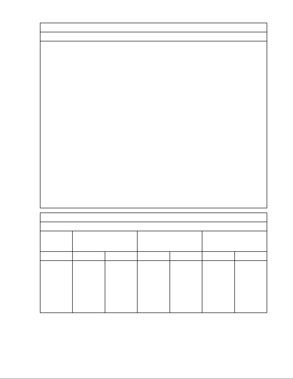
Table 8. Environment requirements (continued)
Environment requirements
Notes:
1. IBM provides the recommended operating environment as the long-term operating environment that
can result in the greatest reliability, energy efciency, and reliability. The allowable operating
environment represents where the equipment is tested to verify functionality. Due to the stresses
that operating in the allowable envelope can place on the equipment, these envelopes must be used
for short-term operation, not continuous operation.
2. Must derate the maximum allowable temperature 1°C (1.8°F) per 175 m (574 ft) above 900 m (2953
ft) up to a maximum allowable elevation of 3050 m (10000 ft).
3. The minimum humidity level is the larger absolute humidity of the -12°C (10.4°F) dew point and the
8% relative humidity. These levels intersect at approximately 25°C (77°F). Below this intersection,
the dew point (-12°C) represents the minimum moisture level, while above it, the relative humidity
(8%) is the minimum. For the upper moisture limit, the limit is the minimum absolute humidity of the
dew point and relative humidity that is stated.
4. The following minimum requirements apply to data centers that are operated at low relative
humidity:
• Data centers that have do not have ESD floors and where people are allowed to wear non-ESD
shoes might want to consider increasing humidity given that the risk of generating 8 kV increases
slightly at 8% relative humidity, when compared to 25% relative humidity.
• All mobile furnishings and equipment must be made of conductive or static dissipative materials
and be bonded to ground.
• During maintenance on any hardware, a properly functioning and grounded wrist strap must be
used by any personnel who comes in contact with information technology (IT) equipment.
5. Equipment that is removed from the original shipping container and is installed, but is powered
down. The allowable non-operating environment is provided to dene the environmental range that
an unpowered system can experience short term without being damaged.
Table 9. Noise emissions for the 9008-22L, 9009-22A, and 9223-22H
Declared noise emission values in accordance with ISO 9296
Production
description
Declared A-weighted
sound power level, L
WA,m
Declared A-weighted
sound pressure level, L
(B)
1, 2, 3, 4, 5
(dB)
Operating Idling Operating Idling Operating Idling
9008-22L,
9009-22A,
and
9223-22H at
23°C
6.5 6.4 52 52 0.3 0.3
(73.4°F)
ambient
temperature
pA,m
Statistical adder for
verication, Kv (B)
10 Power Systems: Site and hardware planning
Page 25
Table 9. Noise emissions for the 9008-22L, 9009-22A, and 9223-22H (continued)
Declared noise emission values in accordance with ISO 9296
1, 2, 3, 4, 5
Production
description
9008-22L,
9009-22A,
and
9223-22H
with PCIe
adapters that
require extra
cooling or at
a
temperature
between
23°C - 27°C
(73.4°F -
80.6°F).
9008-22L,
9009-22A,
and
9223-22H
with
acoustical
doors
installed
Declared A-weighted
sound power level, L
(B)
6
7.4
7.4
WA,m
6
Declared A-weighted
sound pressure level, L
pA,m
Statistical adder for
verication, Kv (B)
(dB)
61 61 0.3 0.3
• 7042-T42
rack: FCs
EC07 and
EC08
• 7965-S42
rack: FCs
ECRA and
ECRB
and with
PCIe
adapters that
require extra
cooling or at
a
temperature
between
23°C - 27°C
(73.4°F -
80.6°F).
6.8 6.8 56 56 0.3 0.3
Site and hardware planning 11
Page 26

Table 9. Noise emissions for the 9008-22L, 9009-22A, and 9223-22H (continued)
Declared noise emission values in accordance with ISO 9296
1, 2, 3, 4, 5
Production
description
Declared A-weighted
sound power level, L
(B)
WA,m
Declared A-weighted
sound pressure level, L
(dB)
pA,m
Statistical adder for
verication, Kv (B)
9008-22L,
9009-22A,
and
9223-22H at
maximum
8.3
6
8.3
6
70 70 0.3 0.3
allowable
ambient
operating
temperature.
Notes:
1. Declared level L
is the upper-limit A-weighted sound power level. Declared level L
WA,m
PA,m
is the
mean A-weighted emission sound pressure level that is measured at the 1-meter bystander
positions.
2. The statistical adder for verication, Kv, is a quantity to be added to the declared mean A-weighted
sound power level, L
, such that there is a 95% probability of acceptance, when using the
WA,m
verication procedures of ISO 9296, if no more than 6.5% of the batch of new equipment has Aweighted sound power levels greater than (L
3. The quantity L
(formerly called L
WA,c
WAd
), can be computed from the sum of L
WA,m
+ Kv).
WA,m
and Kv.
4. All measurements made in conformance with ISO 7779 and declared in conformance with ISO 9296.
5. 10 dB (decibel) equals 1 B (bel).
6. Notice: Government regulations (such as those prescribed by OSHA or European Community
Directives) might govern noise level exposure in the workplace and might apply to you and your
server installation. This IBM system is available in racks with optional acoustical door features that
can help reduce the noise that is emitted from this system. The actual sound pressure levels in your
installation depend upon various factors, including the number of racks in the installation; the size,
materials, and conguration of the room where you designate the racks to be installed; the noise
levels from other equipment; the room ambient temperature, and employees' location in relation to
the equipment. Further, compliance with such government regulations also depends upon various
extra factors, including the duration of employees' exposure and whether employees wear hearing
protection. IBM recommends that you consult with qualied experts in this eld to determine
whether you are in compliance with the applicable regulations.
Table 10. Noise emissions for the 9009-41A
Declared noise emission values in accordance with ISO 9296
Production
description
Declared A-weighted
sound power level, L
WA,m
(B)
Operating Idling Operating Idling Operating Idling
9009-41A
(tower
version (FC
5.8 5.5 43 39 0.3 0.3
EJUB))
12 Power Systems: Site and hardware planning
1, 2, 3, 4, 5
Declared A-weighted
sound pressure level, L
(dB)
pA,m
Statistical adder for
verication, Kv (B)
Page 27

Table 10. Noise emissions for the 9009-41A (continued)
Declared noise emission values in accordance with ISO 9296
1, 2, 3, 4, 5
Production
description
9009-41A
(rack
version)
9009-41A
(rack
version) with
high-power
PCIe
adapters.
9009-41A
(rack
version) with
high-power
PCIe
adapters and
acoustical
doors
installed
• 7042-T42
rack: FCs
EC07 and
EC08
• 7965-S42
rack: FCs
ECRA and
ECRB
Declared A-weighted
sound power level, L
(B)
WA,m
Declared A-weighted
sound pressure level, L
(dB)
pA,m
Statistical adder for
verication, Kv (B)
5.8 5.5 43 39 0.3 0.3
7.3 7.3 60 60 0.3 0.3
6.6 6.6 54 54 0.3 0.3
9009-41A
(rack and
tower
version) at
maximum
allowable
ambient
operating
temperature.
8.0
6
8.0
6
67 67 0.3 0.3
Site and hardware planning 13
Page 28

Table 10. Noise emissions for the 9009-41A (continued)
Declared noise emission values in accordance with ISO 9296
1, 2, 3, 4, 5
Production
description
Declared A-weighted
sound power level, L
(B)
WA,m
Declared A-weighted
sound pressure level, L
(dB)
pA,m
Statistical adder for
verication, Kv (B)
Notes:
1. Declared level L
is the upper-limit A-weighted sound power level. Declared level L
WA,m
PA,m
is the
mean A-weighted emission sound pressure level that is measured at the 1-meter bystander
positions.
2. The statistical adder for verication, Kv, is a quantity to be added to the declared mean A-weighted
sound power level, L
, such that there is a 95% probability of acceptance, when using the
WA,m
verication procedures of ISO 9296, if no more than 6.5% of the batch of new equipment has Aweighted sound power levels greater than (L
3. The quantity L
(formerly called L
WA,c
WAd
), can be computed from the sum of L
WA,m
+ Kv).
WA,m
and Kv.
4. All measurements made in conformance with ISO 7779 and declared in conformance with ISO 9296.
5. 10 dB (decibel) equals 1 B (bel).
6. Notice: Government regulations (such as those prescribed by OSHA or European Community
Directives) might govern noise level exposure in the workplace and might apply to you and your
server installation. This IBM system is available in racks with optional acoustical door features that
can help reduce the noise that is emitted from this system. The actual sound pressure levels in your
installation depend upon various factors, including the number of racks in the installation; the size,
materials, and conguration of the room where you designate the racks to be installed; the noise
levels from other equipment; the room ambient temperature, and employees' location in relation to
the equipment. Further, compliance with such government regulations also depends upon various
extra factors, including the duration of employees' exposure and whether employees wear hearing
protection. IBM recommends that you consult with qualied experts in this eld to determine
whether you are in compliance with the applicable regulations.
Table 11. Noise emissions for the 9009-42A and 9223-42H
Declared noise emission values in accordance with ISO 9296
Production
description
Declared A-weighted
sound power level, L
(B)
WA,m
Declared A-weighted
sound pressure level, L
(dB)
Operating Idling Operating Idling Operating Idling
9009-42A
and
6.6 6.5 53 53 0.3 0.3
9223-42H
9009-42A
and
9223-42H
with high-
7.4
6
7.4
6
61 61 0.3 0.3
power PCIe
adapters.
1, 2, 3, 4, 5
pA,m
Statistical adder for
verication, Kv (B)
14 Power Systems: Site and hardware planning
Page 29
Table 11. Noise emissions for the 9009-42A and 9223-42H (continued)
Declared noise emission values in accordance with ISO 9296
1, 2, 3, 4, 5
Production
description
9009-42A
and
9223-42H
with highpower PCIe
adapters and
acoustical
doors
installed
• 7042-T42
rack: FCs
EC07 and
EC08
• 7965-S42
rack: FCs
ECRA and
ECRB
9009-42A
and
9223-42H at
maximum
allowable
ambient
operating
temperature.
Declared A-weighted
sound power level, L
(B)
WA,m
Declared A-weighted
sound pressure level, L
(dB)
pA,m
Statistical adder for
verication, Kv (B)
6.9 6.9 55 55 0.3 0.3
8.1
6
8.1
6
68 68 0.3 0.3
Site and hardware planning 15
Page 30
Table 11. Noise emissions for the 9009-42A and 9223-42H (continued)
Declared noise emission values in accordance with ISO 9296
1, 2, 3, 4, 5
Production
description
Declared A-weighted
sound power level, L
(B)
WA,m
Declared A-weighted
sound pressure level, L
(dB)
pA,m
Statistical adder for
verication, Kv (B)
Notes:
1. Declared level L
is the upper-limit A-weighted sound power level. Declared level L
WA,m
PA,m
is the
mean A-weighted emission sound pressure level that is measured at the 1-meter bystander
positions.
2. The statistical adder for verication, Kv, is a quantity to be added to the declared mean A-weighted
sound power level, L
, such that there is a 95% probability of acceptance, when using the
WA,m
verication procedures of ISO 9296, if no more than 6.5% of the batch of new equipment has Aweighted sound power levels greater than (L
3. The quantity L
(formerly called L
WA,c
WAd
), can be computed from the sum of L
WA,m
+ Kv).
WA,m
and Kv.
4. All measurements made in conformance with ISO 7779 and declared in conformance with ISO 9296.
5. 10 dB (decibel) equals 1 B (bel).
6. Notice: Government regulations (such as those prescribed by OSHA or European Community
Directives) might govern noise level exposure in the workplace and might apply to you and your
server installation. This IBM system is available in racks with optional acoustical door features that
can help reduce the noise that is emitted from this system. The actual sound pressure levels in your
installation depend upon various factors, including the number of racks in the installation; the size,
materials, and conguration of the room where you designate the racks to be installed; the noise
levels from other equipment; the room ambient temperature, and employees' location in relation to
the equipment. Further, compliance with such government regulations also depends upon various
extra factors, including the duration of employees' exposure and whether employees wear hearing
protection. IBM recommends that you consult with qualied experts in this eld to determine
whether you are in compliance with the applicable regulations.
Table 12. Service clearances
Clearances Front Rear Side
1
Top
1
Operating 762 mm (30 in.) 762 mm (30 in.)
Nonoperating 762 mm (30 in.) 762 mm (30 in.) 762 mm (30 in.) 762 mm (30 in.)
1
Side and top clearances are optional during operation.
Electromagnetic compatibility compliance: CISPR 22; CISPR 32; CISPR 24; FCC, CFR 47, Part 15 (US);
VCCI (Japan); Directive 2014/30/EU (EEA); ICES-003, Issue 6 (Canada); ACMA (Australia, New Zealand);
CNS 13438 (Taiwan); Radio Waves Act (Korea); Commodity Inspection Law (China); TCVN 7189
(Vietnam); MoCI (Saudi Arabia); SI 961 (Israel); EAC (EAEU)
Safety compliance: UL 60950-1:2007 Underwriters Laboratory; CAN/CSA22.2 No. 60950-1-07;
EN60950-1:2006 + Am1 + Am2 European Norm; IEC 60950-1 2nd Edition + Am1 + Am2 and all National
Differences
Special Hardware Management Console considerations
When the server is managed by an HMC, the console must be provided within the same room and within 8
m (26 ft) of the server. For more considerations, see Installing and conguring the HMC.
Note: As an alternative to the local HMC requirement, you can provide a supported device, such as a PC,
with connectivity and authority to operate through a remotely attached HMC. This local device must be in
the same room and within 8 m (26 ft) of your server. This local device must provide functional capabilities
16
Power Systems: Site and hardware planning
Page 31

that are equivalent to the HMC that it replaces. This local device is needed by the service representative
to service the system.
Model 9008-22L, 9009-22A, and 9223-22H Technical Documentation for EU Regulation 617/2013
International Business Machines Corporation
New Orchard Road
Armonk, New York 10504
http://www.ibm.com/customersupport/
IBM Power Systems
Table 13. System characteristics
System characteristics Properties
Product type Computer server
Year rst manufactured 2018
Noise levels (declared A-weighted sound
power level of the computer)
Table 14. Power characteristics
1
8.3 bels (B)
Power characteristics Properties
Internal/external power supply efciency
80 PLUS Verication and Testing Report 1025 W
80 PLUS Verication and Testing Report 1400 W
Maximum power (watts) 1400 W and 1025 W
Idle state power (watts) Unavailable
Sleep mode power (watts) N/A for servers
1. Preliminary data is based on development systems and is subject to change.
Table 15. Test parameters for measurements
Test parameters Properties
Test voltage and frequency 230 V ac at 50 or 60 Hz
Total harmonic distortion of the electricity
supply system
The maximum harmonic content of the input voltage waveform
is equal to or less than 2%. The qualication is compliant with
EN 61000-3-2.
Information and documentation on the
instrumentation setup and circuits that are
used for electrical testing
Measurement methodology that is used to
determine information in this document
ENERGY STAR Test Method for Computer Servers; ECOVA
Generalized Test Protocol for Calculating the Energy Efciency
of Internal Ac-Dc and Dc-Dc Power Supplies
ENERGY STAR Servers Version 2.0 Program Requirements;
ECOVA Generalized Test Protocol for Calculating the Energy
Efciency of Internal Ac-Dc and Dc-Dc Power Supplies
Model 9009-41A, 9009-42A, and 9223-42H Technical Documentation for EU Regulation 617/2013
International Business Machines Corporation
New Orchard Road
Armonk, New York 10504
http://www.ibm.com/customersupport/
IBM Power Systems
Site and hardware planning
17
Page 32

Table 16. System characteristics
System characteristics Properties
Product type Computer server
Year rst manufactured 2018
Noise levels (declared A-weighted sound
power level of the computer)
Table 17. Power characteristics
1
8.3 bels (B)
Power characteristics Properties
Internal/external power supply efciency
80 PLUS Verication and Testing Report 1025 W
80 PLUS Verication and Testing Report 1400 W
Maximum power (watts) 1400 W and 1025 W
Idle state power (watts) Unavailable
Sleep mode power (watts) N/A for servers
1. Preliminary data is based on development systems and is subject to change.
Table 18. Test parameters for measurements
Test parameters Properties
Test voltage and frequency 230 V ac at 50 or 60 Hz
Total harmonic distortion of the electricity
supply system
The maximum harmonic content of the input voltage waveform
is equal to or less than 2%. The qualication is compliant with
EN 61000-3-2.
Information and documentation on the
instrumentation setup and circuits that are
used for electrical testing
Measurement methodology that is used to
determine information in this document
ENERGY STAR Test Method for Computer Servers; ECOVA
Generalized Test Protocol for Calculating the Energy Efciency
of Internal Ac-Dc and Dc-Dc Power Supplies
ENERGY STAR Servers Version 2.0 Program Requirements;
ECOVA Generalized Test Protocol for Calculating the Energy
Efciency of Internal Ac-Dc and Dc-Dc Power Supplies
Expansion unit and migration tower specications
Expansion unit and migration tower specications provide detailed information for your hardware,
including dimensions, electrical, power, temperature, environment, and service clearances.
Select a model to view its specications.
5887 expansion unit
Hardware specications provide detailed information for your expansion unit, including dimensions,
electrical, power, temperature, environment, and service clearances.
Table 19. Dimensions for rack-mounted expansion unit
Weight (with drives
installed) Width
25.4 kg (56.0 lb) 448.6 mm (17.7 in.) 530 mm (20.9 in.) 87.4 mm (3.4 in.)
Depth (including front
bezel)
Height (with support
rails)
18 Power Systems: Site and hardware planning
Page 33

Table 20. Electrical
Electrical characteristics Properties
kVA (maximum)
1
0.32
Rated voltage and frequency 100 - 127 V ac or 200 - 240 V ac at 50 - 60 Hz
Thermal output (maximum)
1
1024 Btu/hr
Power requirements (maximum) 300 W
Power factor 0.94
Leakage current (maximum) 1.2 mA
Phase 1
1
All measurements made in conformance with ISO 7779 and declared in conformance with ISO 9296.
Table 21. Temperature requirements
Operating Nonoperating
10°C - 38°C (50°F - 100.4°F)
1
The maximum 38°C (100.4°F) temperature must be derated 1°C (1.8 °F) per 137 m (450 ft) above 1295 m
1
-40°C - 60°C (-40°F - 140°F)
(4250 ft).
Table 22. Environmental requirements
Environment Operating Nonoperating Maximum altitude
Noncondensing humidity 20% - 80% (allowable)
40% - 55%
(recommended)
8% - 80% (including
condensing)
2134 m (7000 ft) above
sea level
Wet bulb temperature 21°C (69.8°F) 27°C (80.6°F)
Table 23. Noise emissions
1
Properties Operating Idle
L
WAd
L
(1-meter bystander) 43 dB 43 dB
pAm
1
Single drawer in standard 19-inch rack with 24 hard disk drives, nominal environmental conditions, and no
6.0 bels 6.0 bels
front or rear doors on rack.
For a description of noise emission values, see Acoustics.
All measurements made in conformance with ISO 7779 and declared in conformance with ISO 9296.
Table 24. Service clearances for rack-mounted expansion unit
Front Back Sides
914 mm (36 in.) 914 mm (36 in.) 914 mm (36 in.)
Side and top clearances are optional during operation.
Safety compliance: This hardware is designed and certied to meet the following safety standards: UL
60950; CAN/CSA C22.2 No. 60950–00; EN 60950; IEC 60950 including all National Differences
Site and hardware planning
19
Page 34

EMX0 PCIe Gen3 I/O expansion drawer (feature code EMX0)
Hardware specications provide detailed information for your expansion unit, including dimensions,
electrical, power, temperature, environment, and service clearances.
Table 25. Dimensions for rack-mounted expansion unit
Width Depth Height Weight (maximum)
482 mm (19 in.) 802 mm (31.6 in.)
Table 26. Electrical
1,2,3
173 mm (6.8 in.), 4 EIA
units
54.4 kg (120 lb)
Electrical characteristics Properties
AC rated voltage and frequency 100 - 127 V ac or 200 - 240 V ac at 50 or 60 Hz plus or
minus 3 Hz (FC EMXA)
DC rated voltage 192 - 400 V dc (FC EMXB)
Thermal output (maximum) 1740 BTU/hr
Maximum power consumption 510 W
Maximum kVA 0.520
Phase Single
Notes:
1. The power supplies for AC or DC voltage do not change. Only the power chunnel is different. The power
chunnel uses internal cables to carry power from the rear of the system node to the power supplies that are
in the front of the system node.
2. All measurements made in conformance with ISO 7779 and declared in conformance with ISO 9296.
3. AC and HVDC power supplies cannot be mixed in the same server or I/O drawer. IBM recommends that AC
products and HVDC products with HVDC PDUs are installed in separate racks. However, AC and HVDC
products can be supported in the same rack if all grounding (earthing) is done in accordance with the
applicable electrical code or codes. IBM provides documentation for different AC and HVDC products about
the disconnecting means for service. If a different disconnecting means is to be used for service of the
equipment in a rack with AC-powered and DC-powered products, the disconnecting means must be made
clear to service.
Table 27. Environment requirements
Environment Recommended operating Allowable operating Nonoperating
ASHRAE class A3
Airflow direction Front-to-back
Temperature
Humidity range 5.5°C (42°F) dew point
1
18°C - 27°C (64°F - 80°F) 5°C - 40°C (41°F - 104°F) 1°C - 60°C (34°F - 140°F)
(DP) to 60% relative
-12.0°C (10.4°F) DP and
8% - 80% RH
5% - 80% RH
humidity (RH) and 15°C
(59°F) dew point
Maximum dew point 24°C (75°F) 27°C (80°F)
Maximum operating
3050 m (10000 ft)
altitude
20 Power Systems: Site and hardware planning
Page 35

Table 27. Environment requirements (continued)
Environment Recommended operating Allowable operating Nonoperating
Shipping temperature -40°C to 60°C (-40°F to
140°F)
Shipping relative humidity 5% - 100%
1. Derate maximum allowable dry-bulb temperature 1°C per 175 m above 950 m.
Table 28. Service clearances for rack-mounted expansion unit
Front Back Sides
914 mm (36 in.) 914 mm (36 in.) 914 mm (36 in.)
Side and top clearances are optional during operation.
Safety compliance: This hardware is designed and certied to meet the following safety standards: UL
60950; CAN/CSA C22.2 No. 60950–00; EN 60950; IEC 60950 including all National Differences.
ESLL and ESLS storage enclosures
Hardware specications for ESLL and ESLS storage enclosures provide detailed information for your
storage enclosures, including dimensions, electrical, power, temperature, environment, and service
clearances.
Table 29. Dimensions for storage enclosures
Weight (maximum
Width Depth Height
conguration)
37.1 kg (81.8 lb) (ESLL)
448.6 mm (17.7 in.) 744.22 mm (29.3 in.) 87.4 mm (3.4 in.)
31.1 kg (68.6 lb) (ESLS)
Table 30. Electrical
Electrical characteristics Properties
AC rated voltage and frequency 100 - 127 V ac or 200 - 240 V ac at 50 or 60 Hz plus or
minus 3 Hz
Thermal output (maximum) 939 BTU/hr
Maximum power consumption 275 W
Maximum kVA 0.28
Phase Single
Table 31. Environment requirements
Environment Recommended operating Allowable operating Nonoperating
ASHRAE class A3
Airflow direction Front-to-back
Temperature
1
18°C - 27°C (64°F - 80°F) 5°C - 40°C (41°F - 104°F) 1°C - 60°C (34°F - 140°F)
Site and hardware planning 21
Page 36

Table 31. Environment requirements (continued)
Environment Recommended operating Allowable operating Nonoperating
Humidity range 5.5°C (42°F) dew point
(DP) to 60% relative
humidity (RH) and 15°C
(59°F) dew point
Maximum dew point 24°C (75°F) 27°C (80°F)
Maximum operating
altitude
Shipping temperature -40°C to 60°C (-40°F to
Shipping relative humidity 5% - 100%
1. Derate maximum allowable dry-bulb temperature 1°C per 175 m above 950 m.
Table 32. Service clearances for rack-mounted expansion unit
Front Back Sides
914 mm (36 in.) 914 mm (36 in.) 914 mm (36 in.)
Side and top clearances are optional during operation.
Safety compliance: This hardware is designed and certied to meet the following safety standards: UL
60950; CAN/CSA C22.2 No. 60950–00; EN 60950; IEC 60950 including all National Differences.
-12.0°C (10.4°F) DP and
8% - 80% RH
3050 m (10000 ft)
5% - 80% RH
140°F)
Rack specications
Rack specications provide detailed information for your rack, including dimensions, electrical, power,
temperature, environment, and service clearances.
For non-IBM rack specications, see “Rack installation specications for racks that are not purchased
from IBM” on page 70.
Select your rack model to view its specications.
Related reference
Rack installation specications for racks that are not purchased from IBM
Learn about the requirements and specications for installing IBM systems into racks that were not
purchased from IBM.
Planning for the 7014-T00 and 7014-T42 racks
Rack specications provide detailed information for your rack, including dimensions, electrical, power,
temperature, environment, and service clearances.
Some products can have rack installation limitations. Refer to the specic server or product specications
for any restrictions.
The following provide specications for the 7014-T00 and 7014-T42 racks.
22
Power Systems: Site and hardware planning
Page 37

Model 7014-T00 rack
Hardware specications provide detailed information for your rack, including dimensions, electrical,
power, temperature, environment, and service clearances.
Table 33. Dimensions for rack
Rack
conguratio
n
Rack Only
with side
covers
Rack with
standard rear
door only
Rack with
standard
front and
rear doors
Rack with FC
6101 OEM
front door
and standard
rear door
Width Depth Height Weight
(empty)
644 mm
(25.4 in.)
644 mm
(25.4 in.)
644 mm
(25.4 in.)
644 mm
(25.4 in.)
1016 mm
(40.0 in.)
1042 mm
(41.0 in.)
1100 mm
(43.3 in.)
1100 mm
(43.3 in.)
1804 mm
(71.0 in.)
1804 mm
(71.0 in.)
1804 mm
(71.0 in.)
1804 mm
(71.0 in.)
244 kg (535
lb)
254 kg (559
lb)
268 kg (590
lb)
268 kg (590
lb)
Weight
(maximum
EIA unit
capacity
conguratio
n)
816 kg (1795
1
lb)
36 EIA units
N/A N/A
N/A N/A
N/A N/A
Rack with FC
6068 high
644 mm
(25.4 in.)
1100 mm
(43.3 in.)
1804 mm
(71.0 in.)
268 kg (590
lb)
N/A N/A
perforation
front door
and standard
rear door
Rack with FC
6248
644 mm
(25.4 in.)
1413 mm
(55.6 in.)
1804 mm
(71.0 in.)
268 kg (589
lb)
N/A N/A
acoustic
front and
rear doors
1
For more information about rack weight distribution and floor loading, see 7014-T00, 7014-T42, and
0553 rack weight distribution and floor loading.
Table 34. Dimensions for doors
Door model Width Height Depth Weight
Standard front
639 mm (25.2 in.) 1740 mm (68.5 in.) 56 mm (2.3 in.) 14 kg (31 lb)
door
Standard rear door 639 mm (25.2 in.) 1740 mm (76.6 in.) 26 mm (1.0 in.) 11 kg (24 lb)
With acoustic
foam: 14 kg (31 lb)
Site and hardware planning 23
Page 38

Table 34. Dimensions for doors (continued)
Door model Width Height Depth Weight
Standard side
covers
FC 6101 front door
10 mm (0.4 in.)
each
1740 mm (68.5 in.)
each
1042 mm (41.0 in.)
each
18 lbs 8.25 kg (18
lb) each
639 mm (25.2 in.) 1740 mm (68.5 in.) 56 mm (2.3 in.) 14 kg (31 lb)
(OEM)
FC 6068 front door,
639 mm (25.2 in.) 1740 mm (68.5 in.) 56 mm (2.3 in.) 14 kg (31 lb)
high perforation
FC 6248 acoustic
doors, front and
639 mm (25.2 in.)
each
1740 mm (76.6 in.)
each
198 mm (7.8 in.)
each
12.3 kg (27 lb)
each
rear
Table 35. Electrical
1
Electrical characteristics Properties
Power source loading maximum in kVA
2
8.4 (FC 61173)
8.4 (FC EPB8
3,4
)
Notes:
1. The total rack power can be derived from the sum of the power that is used by the drawers in the
rack.
2. For FC EPB8, each side can support a maximum of 600 amps (A) and 10 circuit breakers. The PDP
can hold up to twenty (ten per power source) circuit breakers with ratings between 5 A and 90 A.
Each power source supports up to 8.4 kVA.
3. For more information about FC 6117 and FC EPB8, see “Model 7014-T00 rack with optional DC
power distribution panel” on page 25.
4. Preliminary data is subject to change.
See your individual server or hardware specications for temperature and humidity requirements.
Rack noise levels depend on the number and type of drawers installed. See your server or hardware
specications for specic requirements.
Note: All rack installations require careful site and facilities planning that are designed to both address
the cumulative drawer heat output and provide the airflow volume rates necessary to comply with drawer
temperature requirements. All rack installations require careful site and facilities planning that are
designed to address both the cumulative drawer heat output and provide the airflow volume rates
necessary to comply with drawer temperature requirements. Rack airflow requirements depend on the
number and type of drawers installed.
Note: Acoustic doors are available for IBM racks. Feature code 6248 is available for the 0551 and 7014T00 racks. Feature code 6249 is available for 7014-T42 racks. The overall sound reduction is
approximately 6 dB. The doors add approximately 381 mm (15 in.) to the depth of the racks.
Related reference
7014-T00 and 7014-T42 rack weight distribution and floor loading
24
Power Systems: Site and hardware planning
Page 39

Racks can be heavy when populated with several drawers. Use the Weight distribution distances for racks
when loaded and Floor loading for racks when loaded tables to ensure proper floor loading and weight
distribution.
Model 7014-T00 rack with optional DC power distribution panel
Hardware specications provide detailed information for your rack, including dimensions, electrical,
power, temperature, environment, and service clearances.
Feature code (FC) 6117 (-48 V dc power distribution panel (PDP))
This feature provides a top-mounted, dual DC power distribution panel for a rack that can contain varying
quantities of central processing unit (CPU) drawers, storage subsystems, or both. Up to two DC H80
systems or two DC M80 systems are supported, in addition to up to four DC storage subsystems. This
feature is built without attached power cables. It comes with a series of power connectors that are built
into its rear bulkhead. The appropriate DC power cables are included with supported drawer systems and
plug into the power connectors at the rear of the 6117 PDP.
FC EPB8 (-48 V dc power distribution panel (PDP))
This feature provides a top-mounted -48 V dc PDP for model 7014-T00 racks that can contain varying
quantities of drawers, storage subsystems, and OEM equipment. This feature is preinstalled on the 7014T00 rack. The PDP sits on top of the rack and does not take up any EIA space. The PDP supports
redundant power with a split A and B side. Each side can support up to 10 circuit breakers that are rated 5
- 90 amperes with a maximum load of 600 amperes. FC EPB8 does not include circuit breakers or DC
power cables. The circuit breakers and associated DC power cables are typically supplied with IBM
products. For OEM products, you must provide the applicable circuit breakers and DC power cables.
Note: Front doors are optional on the 7014-T00 rack.
Site and hardware planning
25
Page 40

Figure 1. FC EPB8 - power distribution panel
26
Power Systems: Site and hardware planning
Page 41

Figure 2. FC EPB8 - power distribution panel (top-down view)
Table 36. Dimensions for 7014-T00 rack with FC 6117 or FC EPB8 installed
Dimensions Properties
Width (rack with side panels) 644 mm (25.4 in.)
Depth 1148 mm (45.2 in.)
Height with -48 v DC power only 1926 mm (75.8 in.)
Height with -48 v DC power and overhead cable tray
(normally included with FC EPB8)
Table 37. Environment requirements for FC 6117 and FC EPB8
Environment Recommended operating Allowable operating Nonoperating
Temperature -5°C to 55°C (23°F -
Humidity range 0% - 90% relative
1941 mm (76.4 in.)
131°F)
humidity (RH) (noncondensing)
Site and hardware planning 27
Page 42

Table 37. Environment requirements for FC 6117 and FC EPB8 (continued)
Environment Recommended operating Allowable operating Nonoperating
Shipping temperature -40°C to 70°C (-40°F to
158°F)
Shipping relative humidity 0% - 93%
Model 7014-T42 and 7014-B42 rack
Hardware specications provide detailed information for your rack, including dimensions, electrical,
power, temperature, environment, and service clearances.
Table 38. Dimensions for rack
Rack
conguration
Rack only
with side
covers
Rack with
standard rear
door only
Rack with
standard front
and rear
doors
Rack with FC
6084 OEM
front door and
standard rear
door
Width Depth Height
644 mm (25.4
in.)
644 mm (25.4
in.)
644 mm (25.4
in.)
644 mm (25.4
in.)
1016 mm
(40.0 in.)
1042 mm
(41.0 in.)
1098 mm
(43.3 in.)
1098 mm
(43.3 in.)
2015 mm
(79.3 in.)
2015 mm
(79.3 in.)
2015 mm
(79.3 in.)
2015 mm
(79.3 in.)
1
Weight
(empty)
Weight
(maximum
EIA unit
capacity
conguration
)
261 kg (575
lb)
1597 kg
(3521 lb)2 =
42 EIA units
(1336 kg +
261 kg)
273 kg (602
N/A N/A
lb)
289 kg (636
N/A N/A
lb)
289 kg (636
N/A N/A
lb)
Rack with FC
6069 high
644 mm (25.4
in.)
1098 mm
(43.3 in.)
perforation
front door and
standard rear
door
Rack with FC
ERG7
644 mm (25.4
in.)
1176 mm
(46.3 in.)
770/780 high
perforation
front door and
standard rear
door
28 Power Systems: Site and hardware planning
2015 mm
(79.3 in.)
2015 mm
(79.3 in.)
289 kg (636
lb)
290 kg (639
lb)
N/A N/A
N/A N/A
Page 43

Table 38. Dimensions for rack (continued)
Rack
conguration
Rack with FC
6249 acoustic
front and rear
doors
Rack with FC
6250 high end
appearance
front door and
standard rear
door
Rack with FC
ERGB
acoustic front
door and
standard rear
door
Width Depth Height
644 mm (25.4
in.)
644 mm (25.4
in.)
644 mm (25.4
in.)
1413 mm
(55.6 in.)
1131 mm
(44.5 in.)
1240 mm
(48.8 in.)
2015 mm
(79.3 in.)
2015 mm
(79.3 in.)
2015 mm
(79.3 in.)
1
Weight
(empty)
Weight
(maximum
EIA unit
capacity
conguration
)
289 kg (635
N/A N/A
lb)
N/A N/A
285 kg (627
N/A N/A
lb)
Rack with FC
6858 heat
exchanger
rear door and
standard front
644 mm (25.4
in.)
1222 mm
(48.1 in.)
2015 mm
(79.3 in.)
Empty: 306
kg (675 lb)
Full: 312 kg
(688 lb)
N/A N/A
door
Rack with FC
ERG0 rack
644 mm (25.4
in.)
1303 mm
(51.3 in.)
2015 mm
(79.3 in.)
315 kg (694
lb)
N/A N/A
extension and
standard front
and rear
doors
Notes:
1. The top 6U of the rack can be temporarily detached at the client site to make it easier to move the rack
through doors or elevators. The top 6U is then reattached to the rack frame to provide the full 42U rack
capacity. The rack is approximately 28 cm (11 in.) shorter when the top is removed. The weight of the top
cover is approximately 29 kg (63 lbs).
2. For more information about rack weight distribution and floor loading, see 7014-T00, 7014-T42, and 0553
rack weight distribution and floor loading.
Table 39. Dimensions for doors
Door model Width Height Depth Weight
Standard front door 639 mm (25.2 in.) 1946 mm (76.6 in.) 56 mm (2.3 in.) 16 kg (34 lb)
Site and hardware planning 29
Page 44

Table 39. Dimensions for doors (continued)
Door model Width Height Depth Weight
Standard rear door 639 mm (25.2 in.) 1946 mm (76.6 in.) 26 mm (1.0 in.) 13 kg (27 lb)
With acoustic foam:
16 kg (34 lb)
Standard side
covers (each)
FC 6084 front door
(OEM)
FC 6069 front door,
high perforation
FC ERG7 front door
770/780 high
perforation
FC 6249 acoustic
doors, front and rear
FC 6250 high end
appearance front
door
FC ERGB acoustic
door, front only
FC 6238 high end
appearance side
covers
10 mm (.4 in.) 1740 mm (68.5 in.) 1042 mm (41.0 in.) 18 lbs 8.25 kg(18 lb)
639 mm (25.2 in.) 1946 mm (76.6 in.) 56 mm (2.3 in.) 16 kg (34 lb)
639 mm (25.2 in.) 1946 mm (76.6 in.) 56 mm (2.3 in.) 16 kg (34 lb)
639 mm (25.2 in.) 1946 mm (76.6 in.) 134 mm (5.3 in.) 17 kg (37 lb)
639 mm (25.2 in.)
each
639 mm (25.2 in.)
each
639 mm (25.2 in.) 1946 mm (76.6 in.) 198 mm (7.8 in.) 13.6 kg (30 lb)
10 mm (.4 in.) 1740 mm (68.5 in.) 1042 mm (41.0 in.) 8.5 kg (18 lb)
1946 mm (76.6 in.)
each
1946 mm (76.6 in.)
each
198 mm (7.8 in.)
each
90 mm (3.5 in.)
13.6 kg (30 lb) each
FC 6858 heat
exchanger rear door
FC ERG0 8-inch rack
extension
FC ERG8 ballast
weight specify code
FC EC07 and EC08
acoustic doors,
black IBM, front and
rear
30 Power Systems: Site and hardware planning
639 mm (25.2 in.) 1946 mm (76.6 in.) 147 mm (5.8 in.) Empty: 29.9 kg (66
647 mm (25.4 in.) 1957 mm (77.1 in.) 203 mm (8.0 in.) 27 kg (58.0 lb)
N/A N/A N/A 52.1 kg (115 lb)
639 mm (25.2 in.)
each
1946 mm (76.6 in.)
each
114.3 mm (4.5 in.)
each
lb)
Full: 35.6 kg (78.5
lb)
19 kg (42 lb)
Page 45

Table 40. Electrical
1
Electrical characteristics Properties
Power source loading maximum in kVA For more information about rack power distribution
units and power cord options, see Power distribution
unit and power cord options for 7014 racks.
1
The total rack power can be derived from the sum of the power that is used by the drawers in the rack.
See your individual server or hardware specications for temperature and humidity requirements.
Rack noise levels depend on the number and type of drawers installed. See your server or hardware
specications for specic requirements.
Note: All rack installations require careful site and facilities planning that is designed to both address the
cumulative drawer heat output and provide the airflow volume rates necessary to comply with drawer
temperature requirements. All rack installations require careful site and facilities planning that is
designed to address both the cumulative drawer heat output and provide the airflow volume rates
necessary to comply with drawer temperature requirements. Rack airflow requirements depend on the
number and type of drawers installed.
Note: Acoustic doors are available for IBM racks. Feature code 6248 is available for 7014-T00 racks.
Feature code 6249 is available for 7014-T42 racks. The overall sound reduction is approximately 6 dB.
The doors add approximately 381 mm (15 in.) to the depth of the racks.
Service clearances
Table 41. Service clearances for 7014-T00 and 7014-T42 racks
Front Rear Sides
915 mm (36 in.) 915 mm (36 in.) 915 mm (36 in.)
Note: Recommended minimum vertical service clearance from the floor is 2439 mm (8 ft).
Figure 3 on page 32 provides the caster and leveler locations for 7014-T00 and 7014-T42 racks.
Site and hardware planning
31
Page 46

Figure 3. Caster and leveler locations
Note: Rack units are large and heavy and are not easily moved. As maintenance activities require access
at both the front and the back, extra room is needed. The footprint illustration does not show the radius of
the swinging doors on the I/O rack. A service clearance of 915 mm (36 in.) needs to be maintained on
front, rear, and sides of the I/O rack.
Related reference
7014-T00 and 7014-T42 rack weight distribution and floor loading
Racks can be heavy when populated with several drawers. Use the Weight distribution distances for racks
when loaded and Floor loading for racks when loaded tables to ensure proper floor loading and weight
distribution.
Related information
Planning for the installation of rear door heat exchangers
32
Power Systems: Site and hardware planning
Page 47

7014-T00 and 7014-T42 service clearances and caster location
Use the service clearances and caster locations for 7014-T00 and 7014-T42 racks to plan the correct
service clearances and caster locations for your rack.
Service clearances
Table 42. Service clearances for 7014-T00, 7014-T42, and 0553 racks
Front Rear Sides
915 mm (36 in.) 915 mm (36 in.) 915 mm (36 in.)
Note: Recommended minimum vertical service clearance from the floor is 2439 mm (8 ft).
Figure 4 on page 34 provides the caster and leveler locations for 7014-T00 and 7014-T42 racks.
Site and hardware planning 33
Page 48

Figure 4. Caster and leveler locations
Note: Rack units are large and heavy and are not easily moved. As maintenance activities require access
at both the front and the back, extra room is needed. The footprint illustration does not show the radius of
the swinging doors on the I/O rack. A service clearance of 915 mm (36 in.) needs to be maintained on
front, rear, and sides of the I/O rack.
Feature code (FC) ERG0
FC ERG0 is an optional rear rack extender that can be used for 7014-T42 racks. The extender is installed
on the rear of the 7014-T42 rack and provides 203 mm (8 in.) of extra space to hold cables on the side of
the rack and to keep the center area clear for cooling and service access.
34
Power Systems: Site and hardware planning
Page 49

Figure 5. FC ERG0 rear rack extender (top-down view)
Site and hardware planning
35
Page 50

Figure 6. FC ERG0 assembled view
7014-T00 and 7014-T00 multiple attachment racks
Model 7014-T00 or 7014-T42 racks can be bolted together in a multiple-rack arrangement. This gure
shows that arrangement.
A kit is available including the bolts, spacers, and decorative trim pieces to cover the 25.4 mm (1 in.)
space. For service clearances, see the service clearances as shown in the table for the model 7014-T00
rack.
Related reference
Model 7014-T00 rack
36
Power Systems: Site and hardware planning
Page 51

Hardware specications provide detailed information for your rack, including dimensions, electrical,
power, temperature, environment, and service clearances.
7014-T00 and 7014-T42 rack weight distribution and floor loading
Racks can be heavy when populated with several drawers. Use the Weight distribution distances for racks
when loaded and Floor loading for racks when loaded tables to ensure proper floor loading and weight
distribution.
The 7014-T00 and 7014-T42 racks can be heavy when several drawers are present. The following table
shows the necessary weight distribution distances for the 7014-T00 and 7014-T42 racks when loaded.
Table 43. Weight distribution distances for racks when loaded
Rack System
weight
2
1
Width
Depth
2
Weight distribution distance
3
Front and back Left and right
7014-T004816 kg
(1795 lb)
7014-T005816 kg
(1795 lb)
7014-T006816 kg
(1795 lb)
7014-T424930 kg
(2045 lb)
7014-T425930 kg
(2045 lb)
7014-T426930 kg
(2045 lb)
623 mm
(24.5 in)
623 mm
(24.5 in)
623 mm
(24.5 in)
623 mm
(24.5 in)
623 mm
(24.5 in)
623 mm
(24.5 in)
1021 mm
(40.2 in)
1021 mm
(40.2 in)
1021 mm
(40.2 in)
1021 mm
(40.2 in)
1021 mm
(40.2 in)
1021 mm
(40.2 in)
515.6 mm (20.3 in), 477.5
mm (18.8 in)
515.6 mm (20.3 in), 477.5
mm (18.8 in)
515.6 mm (20.3 in), 477.5
mm (18.8 in)
515.6 mm (20.3 in), 477.5
mm (18.8 in)
515.6 mm (20.3 in), 477.5
mm (18.8 in)
515.6 mm (20.3 in), 477.5
mm (18.8 in)
467.4 mm (18.4 in)
0
559 mm (22 in)
467.4 mm (18.4 in)
0
686 mm (27 in)
Notes:
1. Maximum weight of fully populated rack, units are lb with kg in parentheses.
2. Dimensions without covers, units are mm with inches in parentheses.
3. The weight distribution distance in all four directions is the area around the rack perimeter (minus covers)
necessary to distribute the weight beyond the perimeter of the rack. Weight distribution areas cannot
overlap with adjacent computer equipment weight distribution areas. Units are inches with mm in
parentheses.
4. Weight distribution distance is 1/2 the service clearance values that are shown in the gure plus cover
thickness.
5. No left and right weight distribution distance.
6. Left and right weight distribution distance that is required for a 70 lb/ft2 raised floor loading objective.
The following table shows the necessary floor loading for the 7014-T00 and 7014-T42 racks when
loaded.
Table 44. Floor loading for racks when loaded
Rack Floor loading
7014-T00
7014-T00
7014-T00
Raised kg/m
2
3
4
366.7 322.7 75 66
734.5 690.6 150.4 141.4
341 297 70 61
1
Non-raised kg/m
1
Raised lb/ft
1
Non-raised lb/ft
Site and hardware planning 37
1
Page 52

Table 44. Floor loading for racks when loaded (continued)
Rack Floor loading
7014-T42
7014-T42
7014-T42
Raised kg/m
2
3
4
403 359 82.5 73.5
825 781 169 160
341.4 297.5 70 61
1
Non-raised kg/m
1
Raised lb/ft
1
Non-raised lb/ft
1
Notes:
1. Dimensions without covers, units are mm with inches in parentheses.
2. Weight distribution distance is one half of the service clearance values that is shown in the gure plus cover
thickness.
3. No left and right weight distribution distance.
4. Left and right weight distribution distance that is required for a 70 lb/ft2 raised floor loading objective.
Related reference
Model 7014-T42 and 7014-B42 rack
Hardware specications provide detailed information for your rack, including dimensions, electrical,
power, temperature, environment, and service clearances.
Model 7014-T00 rack
Hardware specications provide detailed information for your rack, including dimensions, electrical,
power, temperature, environment, and service clearances.
Planning for the 7953-94X and 7965-94Y rack
Rack specications provide detailed information for your rack, including dimensions, electrical, power,
temperature, environment, and service clearances.
The following provide specications for the 7953-94X and 7965-94Y rack.
Model 7953-94X and 7965-94Y rack
Hardware specications provide detailed information for your rack, including dimensions, electrical,
power, temperature, environment, and service clearances.
Table 45. Dimensions for rack
Weight
(Maximum
Rack only
Rack with
standard
doors
Width Depth Height Weight (Empty)
600 mm
(23.6 in.)
600 mm
(23.6 in.)
1095 mm
(43.1 in.)
1145.5 mm
(45. in.)
2002 mm (78.8
in.)
2002 mm (78.8
in.)
130 kg (287 lb)
138 kg (304 lb) N/A N/A
conguration)
1140 kg (2512
lb)
1206.2 Rack with
triplex doors
600 mm
(23.6 in.)
1228.8 mm
(47.5 - 48.4
2002 mm (78.8
in.)
147 kg (324 lb) N/A N/A
in.)
EIA unit
capacity
42 EIA
units
Rack with
rear door
heat
exchanger
600 mm
(23.6 in.)
1224 mm
(48.2 in.)
2002 mm (78.8
in.)
indicator
38 Power Systems: Site and hardware planning
169 kg (373 lb) N/A N/A
Page 53

Table 45. Dimensions for rack (continued)
Weight
Width Depth Height Weight (Empty)
(Maximum
conguration)
EIA unit
capacity
Note: When the rack is delivered or is moved, outriggers are needed for stability. For more information about
outriggers, see Side stabilizing outriggers.
Table 46. Dimensions for doors
Door model Width Height Depth Weight
Standard front
door (FC EC01)
and
597 mm (23.5
in.)
1925 mm (75.8 in.) 22.5 mm (0.9 in.) 7.7 kg (17 lb)
standard back
door (FC EC02)
Triplex door (FC
3
EU21)
1
Measured from the front flat surface of the door.
2
Measured from the IBM logo on the front of the door.
3
Multiple racks that are placed side-by-side must have a 6 mm (0.24 in.) minimum clearance between racks to
597.1 mm (23.5
in.)
1923.6 mm (75.7 in.)
105.7 mm (4.2 in.)
128.3 mm (5.2 in.)
1
2
16.8 kg (37 lb)
allow the triplex front door to hinge properly. Feature code EC04 (Rack suite attachment kit) can be used to
maintain the 6 mm (0.24 in.) minimum clearance between racks.
Table 47. Dimensions for side covers
1
Depth Height Weight
885 mm (34.9 in.) 1870 mm (73.6 in.) 17.7 kg (39 lb)
1
Side covers do not increase the overall width of the rack.
Table 48. Temperature requirements
Operating Nonoperating
10°C - 38°C (50°F - 100.4°F)
1
The maximum 38°C (100.4°F) temperature must be derated 1°C (1.8 °F) per 137 m (450 ft) above 1295 m
1
-40°C to 60°C (-40°F to 140°F)
(4250 ft).
Table 49. Environmental requirements
Environment Operating Nonoperating Maximum altitude
Noncondensing humidity 20% - 80% (allowable)
40% - 55%
(recommended)
8% - 80% (including
condensing)
2134 m (7000 ft) above
sea level
Wet bulb temperature 21°C (69.8°F) 27°C (80.6°F)
Site and hardware planning 39
Page 54

Table 50. Service clearances
Front Back Side
1
915 mm (36 in.) 915 mm (36 in.) 610 mm (24 in.)
1
Side service clearance is only required when outriggers are on the rack. Side service clearance is not required
during normal operation of the rack when outriggers are not installed.
Rear door heat exchanger
Specications for Power orderable feature code (FC): EC05 - Rear door heat exchanger indicator (Model
1164-95X).
Table 51. Dimensions for rear door heat exchanger
Width Depth Height Weight (empty) Weight (lled)
600 mm (23.6 in.) 129 mm (5.0 in.) 1950 mm (76.8 in.) 39 kg (85 lb) 48 kg (105 lb)
For more information, see Model 1164-95X rear door heat exchanger.
Electrical
For electrical requirements, see Power distribution unit and power cord options.
Features
The 7953-94X and 7965-94Y rack has the following features available for use:
• Recirculation prevention plate that is installed at the bottom, front of the rack.
• Stabilizer bracket that is installed at the front of the rack.
Caster locations
The following diagram provides the caster locations for the 7953-94X and 7965-94Y rack.
40
Power Systems: Site and hardware planning
Page 55

Figure 7. Caster locations
Cabling the 7953-94X and 7965-94Y rack
Learn about the different cable routing options available for the 7953-94X and 7965-94Y rack.
Cabling within the rack
Side cable channels are available in the rack to route cables. Two cable channels are on each side of the
rack as shown in Figure 8 on page 42.
Site and hardware planning
41
Page 56

Figure 8. Cabling within the rack
Cabling under the floor
A cable access bar on the bottom rear of the rack helps to route the cables, leaving the rack in place. This
bar can be removed for installation and then reattached after the rack is installed and cabled.
42
Power Systems: Site and hardware planning
Page 57

Figure 9. Cable access bar
Cabling overhead
Front and rear rectangular cable access openings that are on the top of the rack cabinet allow cables to
be routed up and out of the rack. Cable access covers are adjustable by loosing the side screws and
sliding the covers forward or backward.
Site and hardware planning
43
Page 58

Figure 10. Cable access covers
Side stabilizing outriggers
Learn about the side stabilizing outriggers available for the 7953-94X and 7965-94Y rack.
The outriggers are stabilizers with wheels that are installed on the sides of the rack cabinet. The
outriggers can be removed only after the rack is in the nal location and is not moved more than 2 m (6 ft)
away in any direction.
To remove the outriggers, use a 6 mm hex wrench to remove the four bolts that attach each outrigger to
the rack cabinet.
Keep each of the outriggers and bolts in a safe place for future use when you move the rack. Reinstall the
outriggers to move the rack cabinet to another location that is greater than 2 m (6 ft) away from its
current location.
44
Power Systems: Site and hardware planning
Page 59

Table 52. Dimensions for rack with outriggers
EIA unit
Width Depth Height Weight
780 mm (30.7 in.) 1095 mm (43.1 in.) 2002 mm (78.8 in.) 261 kg (575 lb) 42 EIA units
capacity
Figure 11. Outrigger locations
Site and hardware planning
45
Page 60

Multiple racks
Learn how to attach multiple 7953-94X and 7965-94Y racks together.
Multiple 7953-94X and 7965-94Y racks can be attached together by using attachment brackets that
connect the units at the front of the rack. See Figure 12 on page 46.
Figure 12. Attachment brackets
46
Power Systems: Site and hardware planning
Page 61

Model 1164-95X rear door heat exchanger
Learn about the specications of the 1164-95X rear door heat exchanger (feature code ECR2).
Model 1164-95X rear door heat exchanger specications
Table 53. Dimensions for the 1164-95X rear door heat exchanger
1
Width
Depth Height Weight (empty) Weight (lled)
600 mm (23.6 in.) 129 mm (5.0 in.) 1950 mm (76.8 in.) 39 kg (85.0 lb) 48 kg (105.0 lb)
1. The width is the inside width of the machine when installed in the U space of the rack. The width of the front
bezel is 482 mm (19.0 in.).
Water specications
• Pressure
– Normal operation: <137.93 kPa (20 psi)
– Maximum: 689.66 kPa (100 psi)
• Volume
– Approximately 9 liters (2.4 gallons)
• Temperature
– Water temperature must be above the dew point in the data center
– 18°C ± 1°C (64.4°F ± 1.8°F) for ASHRAE Class 1 Environment
– 22°C ± 1°C (71.6°F ± 1.8°F) for ASHRAE Class 2 Environment
• Required water flow rate (as measured from the supply entrance to the heat exchanger)
– Minimum: 22.7 liters (6 gallons) per minute
– Maximum: 56.8 liters (15 gallons) per minute
Heat exchanger performance
A heat removal of 100% indicates that an amount of heat that is equivalent to that generated by the
devices has been removed by the heat exchanger and the average air temperature leaving the heat
exchanger is identical to that entering the rack (27°C (80.6°F) in this example). Heat removal in excess of
100% indicates that the heat exchanger not only removed all of the heat that was generated by the
devices, but further cooled the air so that the average air temperature that is leaving the rack is actually
lower than air temperature that is entering the rack.
To help maintain optimum performance of the rear door heat exchanger and provide proper cooling for all
rack components, you must take the following precautions:
• Install ller panels over all unoccupied bays.
• Route signal cables at the rear of the rack so that they enter or exit the cabinet through the top and
bottom air baffles.
• Bundle signal cables together in a rectangle so that the upper and lower air-baffle sliders are closed as
far as possible. Do not bundle signal cables together in a circular formation.
Site and hardware planning
47
Page 62

Figure 13. Typical performance of the heat exchanger, 20 kW heat load
Figure 14. Typical performance of the heat exchanger, 30 kW heat load
Water specications for the secondary cooling loop
Important:
48
Power Systems: Site and hardware planning
Page 63

The water that is being supplied to the heat exchanger must meet the requirements that are described in
this section.
Do not use glycol solutions because they can adversely affect the cooling performance of the heat
exchanger.
Cooling loop requirements
A secondary cooling loop, separate from the main site cooling loop, is required for the rear door heat
exchanger. Cooling distribution units are available from suppliers such as Coolcentric.
The secondary cooling loop must meet the requirements that are outlined in the water chemistry
specication. For more information about water chemistry requirements, see Water cooling system
specication and requirements.
Water-supply requirements for secondary loops
Learn about the specic characteristics of the system that supplies the chilled conditioned water to the
heat exchanger.
Temperature:
The heat exchanger and its supply hose and return hoses are not insulated. Avoid any condition that
might cause condensation. The temperature of the water inside the supply hose, return hose, and
heat exchanger must be kept above the dew point of the location where the heat exchanger is being
used.
Attention:
chilled water can be as cold as 4°C - 6°C (39°F - 43°F).
Important:
The system that supplies the cooling water must be able to measure the room dew point and
automatically adjust the water temperature accordingly. Otherwise, the water temperature must be
above the maximum dew point for that data center installation. For example, the following minimum
water temperature must be maintained:
• 18°C plus or minus 1°C (64.4°F plus or minus 1.8°F). This specication is applicable within an
ASHRAE Class 1 Environmental Specication that requires a maximum dew point of 17°C (62.6°F).
• 22°C plus or minus 1°C (71.6°F plus or minus 1.8°F). This specication is applicable within an
ASHRAE Class 2 Environmental Specication that requires a maximum dew point of 21°C (69.8°F).
See the ASHRAE document Thermal Guidelines for Data Processing Environments.
Pressure:
The water pressure in the secondary loop must be less than 690 kPa (100 psi). Normal operating
pressure at the heat exchanger must be 414 kPa (60 psi) or less.
Flow rate:
The flow rate of the water in the system must be in the range of 23 - 57 liters (6 - 15 gallons) per
minute.
Pressure drop versus flow rate for heat exchangers (including quick-connect couplings) is dened as
approximately 103 kPa (15 psi) at 57 liters (15 gallons) per minute.
Typical primary chilled water is too cold for use in this application because building
Water volume limits:
The heat exchanger holds approximately 9 liters (2.4 gallons). Fifteen meters (50 ft) of 19 mm (0.75
in.) supply and return hoses hold approximately 9.4 liters (2.5 gallons). To minimize exposure to
flooding in the case of leaks, the entire product cooling system (heat exchanger, supply hose, and
return hose), excluding any reservoir tank, must have a maximum 18.4 liters (4.8 gallons) of water.
This is a cautionary statement, not a functional requirement. Also, consider using leak detection
methods on the secondary loop that supplies water to the heat exchanger.
Site and hardware planning
49
Page 64

Air exposure:
The secondary cooling loop is a closed loop, with no continuous exposure to room air. After you ll the
loop, remove all air from the loop. An air bleed valve is provided at the top of a heat exchanger
manifold for purging all air from the system.
Water delivery specications for secondary loops
Learn about the various hardware components that make up the delivery system secondary loop that
provides the chilled, conditioned water to the heat exchanger. The delivery system includes pipes, hoses,
and the required connection hardware to connect the hoses to the heat exchanger. Hose management
can be used in raised-floor and non-raised-floor environments.
The heat exchanger can remove 100% or more of the heat load from an individual rack when it is running
under optimum conditions.
The primary cooling loop is considered to be the building chilled-water supply or a modular chiller unit.
The primary loop must not be used as a direct source of coolant for the heat exchanger.
Procurement and installation of the components that are needed to create the secondary cooling loop
system are required for this design and are your responsibility. The main purpose is to provide examples
of typical methods of secondary loop setup and operating characteristics that are needed to provide an
adequate and safe supply of water to the heat exchanger.
Attention:
The overpressure safety device must meet the following requirements:
• Comply with ISO 4126-1.
• Be installed so that it is easily accessed for inspection, maintenance, and repair.
• Be connected as close as possible to the device that it is intended to protect.
• Be adjustable only with the use of a tool.
• Have a discharge opening that is directed so that discharged water or fluid does not create a
hazard or be directed toward any person.
• Be of adequate discharge capacity to ensure that the maximum working pressure is not
exceeded.
• Be installed without a shutoff valve between the overpressure safety device and the protected
device.
Read the following guidelines before you design the installation:
• A method for monitoring and setting the total flow rate that is delivered to all of the heat exchangers is
required. This can be a discrete flowmeter that is built into the flow loop or a flowmeter within the
secondary loop of the coolant distribution unit (CDU).
• After you set the total flow rate for all of the heat exchangers by using a flowmeter, it is important to
design the plumbing so that it provides the flow rate that you want for each heat exchanger and
provides a way to verify the flow rate. Other methods, such as inline or external flowmeters, can provide
a more accurate method for setting the flow rate through the individual shutoff valves.
Manifolds and piping:
Manifolds that accept large-diameter feed pipes from a pump unit are the preferred method for
splitting the flow of water to smaller-diameter pipes or hoses that are routed to individual heat
exchangers. Manifolds must be constructed of materials that are compatible with the pump unit and
related piping. The manifolds must provide enough connection points to allow a matching number of
supply and return lines to be attached, and the manifolds must match the capacity rating of the
pumps and the loop heat exchanger (between the secondary cooling loop and the building chilledwater source). Anchor or restrain all manifolds to provide the required support to avoid movement
when quick-connect couplings are connected to the manifolds.
Example of manifold supply pipe sizes:
50
Power Systems: Site and hardware planning
Page 65

• Use a 50.8 mm (2 in.) or larger supply pipe to provide the correct flow to three 19 mm (0.75 in.)
supply hoses, with a 100 kW coolant distribution unit (CDU).
• Use a 63.5 mm (2.50 in.) or larger supply pipe to provide the correct flow to four 19 mm (0.75 in.)
supply hoses, with a 120 kW CDU.
• Use an 88.9 mm (3.50 in.) or larger supply pipe to provide the correct flow to nine 19 mm (0.75 in.)
supply hoses, with a 300 kW CDU.
To stop the flow of water in individual legs of multiple circuit loops, install shutoff valves for each
supply and return line. This provides a way to service or replace an individual heat exchanger without
affecting the operation of other heat exchangers in the loop.
To ensure that water specications are being met and that the optimum heat removal is taking place,
use temperature and flow metering (monitoring) in secondary loops.
Anchor or restrain all manifolds and pipes to provide the required support and to avoid movement
when quick-connect couplings are being attached to the manifolds.
Flexible hoses and connections to manifolds and heat exchangers:
Pipe and hose congurations can vary. You can determine the best conguration for your installation
by analyzing the needs of your facilities, or a site preparation representative can provide this analysis.
Flexible hoses for the cold-water supply and warm water return are provided with the delivery of the
rear door heat exchanger (allowing needed movement for opening and closing the rack rear door). The
customer needs to supply a 2.54 cm (1 in.) female national pipe thread (NPT) tting for each supply
and return hose connection to the facility. The IBM supplied hoses contain the quick connect ttings
to mate to the ttings on the rear door heat exchanger.
Use solid piping or tubing that has a minimum inner diameter of 19 mm (0.75 in.) and the fewest
possible joints between a manifold and a heat exchanger in each secondary loop.
Related information
Installing the rear door heat exchanger
Planning for the 7965-S42 rack
Rack specications provide detailed information for your rack, including dimensions, electrical, power,
temperature, environment, and service clearances.
Model 7965-S42 rack specications
Hardware specications provide detailed information for your rack, including dimensions, electrical,
power, temperature, environment, and service clearances.
Table 54. Dimensions for rack
Width Depth Height Weight (Empty)
Rack only
Rack with two
standard doors
Rack with rear
door heat
exchanger (dry)
and standard
doors
600 mm (23.6
in.)
600 mm (23.6
in.)
600 mm (23.6
in.)
1070 mm (42.1
in.)
1132 mm (44.6
in.)
1231 mm (48.5
in.)
2020 mm (79.5 in.) 166 kg (365 lb) 42 EIA units
2020 mm (79.5 in.) 177 kg (391 lb) 42 EIA units
2020 mm (79.5 in.) 210 kg (463 lb) 42 EIA units
EIA unit
capacity
Site and hardware planning 51
Page 66

Table 54. Dimensions for rack (continued)
EIA unit
Width Depth Height Weight (Empty)
capacity
Rack with highend
appearance
front door and
600 mm (23.6
in.)
1201 mm (47.3
in.)
2020 mm (79.5 in.) 181 kg (398 lb) 42 EIA units
rear door
Table 55. Weight capacity limits
Characteristics Maximum weight EIA unit capacity
Dynamic (rolling) 1134 kg (2500 lb) 18 kg (40 lb) / EIA average
Static 1678 kg (3700 lb) 32 kg (70 lb) / EIA average
Seismic certied 1170 (2580 lb) 20 kg (45 lb) / EIA maximum
Table 56. Dimensions for doors
Door model Width Height Depth Weight
Standard front
door and
standard back
590 mm (23.2
in.)
1942 mm (76.5 in.) 31 mm (1.2 in.) 5.9 kg (13 lb)
door
Rear door heat
exchanger door
High-end
appearance front
door
FC ECRC and
ECRD acoustic
600 mm (23.6
in.)
590 mm (23.2
in.)
590 mm (23.2
in.)
1950 mm (76.8 in.) 129 mm (5.0 in.)
1942 mm (76.5 in.) 100 mm (3.9 in.) 9.1 kg (20 lb)
1942 mm (76.5 in.) 115.5 mm (4.6 in) 17.7 kg (39 lb)
39 kg (85 lb) - empty
48 kg (105 lb) - lled
front and rear
doors, black IBM
FC ECRC and
ECRD acoustic
590 mm (23.2
in.)
1942 mm (76.5 in.) 110 mm (4.3 in) 17.7 kg (39 lb)
front and rear
doors, black OEM
Table 57. Dimensions for side covers
Width
1
Depth Height Weight
2
12 mm (0.5 in.) 1070 mm (42.1 in.) 1942 mm (76.5 in.) 20 kg (44 lb)
1
Side covers increase the overall width of the rack by 12 mm (0.5 in.) per side, but are only used on the ends
of the rows.
2
Weight is for each side cover.
52 Power Systems: Site and hardware planning
Page 67

Table 58. Environment requirements
1
Environment Recommended operating Allowable operating Nonoperating
ASHRAE class A3
Airflow direction Front-to-back
Temperature
2
18°C - 27°C (64°F - 80°F) 5°C - 40°C (41°F - 104°F) 1°C - 60°C (34°F - 140°F)
Humidity range 5.5°C (42°F) dew point
(DP) to 60% relative
-12.0°C (10.4°F) DP and
8% - 80% RH
8% - 80% RH
humidity (RH) and 15°C
(59°F) dew point
Maximum dew point 24°C (75°F) 27°C (80°F)
Maximum operating
3050 m (10000 ft)
altitude
Shipping temperature -40°C to 60°C (-40°F to
140°F)
Shipping relative humidity 5% - 100%
1. The nal ASHRAE class is determined by the hardware that is installed in the rack. Individual specications
for each piece of hardware must be reviewed.
2. Derate maximum allowable dry-bulb temperature 1°C per 175 m above 950 m. IBM recommends a
temperature range of 18°C - 27°C (64°F - 80.6°F).
Table 59. Service clearances
1
Front
Back
915 mm (36 in.) 915 mm (36 in.)
1
Storage racks require larger service clearances in the front of the rack.
Rear door heat exchanger
Specications for Power orderable feature code (FC) EC05 (Rear door heat exchanger indicator (Model
1164-95X)).
Table 60. Dimensions for rear door heat exchanger
Width Depth Height Weight (empty) Weight (lled)
600 mm (23.6 in.) 129 mm (5.0 in.) 1950 mm (76.8 in.) 39 kg (85 lb) 48 kg (105 lb)
For more information, see “Model 1164-95X rear door heat exchanger” on page 47.
Electrical
For electrical requirements, see Power distribution unit and power cord options.
Floor cutout
Racks with water hoses and power cords that exit from the bottom of the rack require a floor tile cutout of
at least 30.48 cm (12 in.) long by 22.86 cm (9 in.) wide. Due to the hose bend radii, the hole must be
positioned towards the side of the rack without the manifold (the left side of the rack when looking at the
rear of the rack). The left edge of the hole must be at least 11.43 cm (4.5 in.) from the side and 3.81 cm
(1.5 in.) from the back edge of the rack (not including doors). Hole placement on the tile depends on the
location of the rack, tile size, and tile load limitations.
Site and hardware planning
53
Page 68

Figure 15. Floor cutout
Caster and leveler locations
The following diagram provides the caster and leveler locations for the 7965-S42 rack.
54
Power Systems: Site and hardware planning
Page 69

Figure 16. Caster and leveler locations
Cabling the 7965-S42 rack
Learn about the different cable routing options available for the 7965-S42 rack.
Cabling within the rack
Side cable channels are available in the rack to route cables. Three cable channels are on each side of the
rack.
Site and hardware planning
55
Page 70

Figure 17. Cabling within the rack
Cabling under the floor
Cables can be routed straight down through the side channels of the rack or routed towards the center of
the opening.
56
Power Systems: Site and hardware planning
Page 71

Figure 18. Cabling under the floor
Cabling overhead
Front and rear cable access openings that are on the top of the rack cabinet allow cables to be routed up
and out of the rack. Cable access covers on the rear are adjustable by loosening the side screws and
sliding the covers forward or backward. Because of the smaller size of the cable openings in front, cables
that pass through this area must be minimized.
Site and hardware planning
57
Page 72

Figure 19. Cabling overhead
Multiple racks
Learn how to attach multiple 7965-S42 racks together.
Multiple 7965-S42 racks can be attached together. For racks that are on a 600 mm (23.6 in.) pitch, you
can use screws to clamp the racks together. For racks that are on a 609 mm (24.0 in.) pitch, two spacer
brackets must be added to set the proper spacing before you can use screws to clamp the racks together.
58
Power Systems: Site and hardware planning
Page 73

Figure 20. Attaching multiple racks with spacer brackets
Model 1164-95X rear door heat exchanger
Learn about the specications of the 1164-95X rear door heat exchanger (feature code ECR2).
Model 1164-95X rear door heat exchanger specications
Table 61. Dimensions for the 1164-95X rear door heat exchanger
1
Width
Depth Height Weight (empty) Weight (lled)
600 mm (23.6 in.) 129 mm (5.0 in.) 1950 mm (76.8 in.) 39 kg (85.0 lb) 48 kg (105.0 lb)
1. The width is the inside width of the machine when installed in the U space of the rack. The width of the front
bezel is 482 mm (19.0 in.).
Water specications
• Pressure
– Normal operation: <137.93 kPa (20 psi)
– Maximum: 689.66 kPa (100 psi)
• Volume
– Approximately 9 liters (2.4 gallons)
• Temperature
– Water temperature must be above the dew point in the data center
– 18°C ± 1°C (64.4°F ± 1.8°F) for ASHRAE Class 1 Environment
Site and hardware planning
59
Page 74

– 22°C ± 1°C (71.6°F ± 1.8°F) for ASHRAE Class 2 Environment
• Required water flow rate (as measured from the supply entrance to the heat exchanger)
– Minimum: 22.7 liters (6 gallons) per minute
– Maximum: 56.8 liters (15 gallons) per minute
Heat exchanger performance
A heat removal of 100% indicates that an amount of heat that is equivalent to that generated by the
devices has been removed by the heat exchanger and the average air temperature leaving the heat
exchanger is identical to that entering the rack (27°C (80.6°F) in this example). Heat removal in excess of
100% indicates that the heat exchanger not only removed all of the heat that was generated by the
devices, but further cooled the air so that the average air temperature that is leaving the rack is actually
lower than air temperature that is entering the rack.
To help maintain optimum performance of the rear door heat exchanger and provide proper cooling for all
rack components, you must take the following precautions:
• Install ller panels over all unoccupied bays.
• Route signal cables at the rear of the rack so that they enter or exit the cabinet through the top and
bottom air baffles.
• Bundle signal cables together in a rectangle so that the upper and lower air-baffle sliders are closed as
far as possible. Do not bundle signal cables together in a circular formation.
Figure 21. Typical performance of the heat exchanger, 20 kW heat load
60
Power Systems: Site and hardware planning
Page 75

Figure 22. Typical performance of the heat exchanger, 30 kW heat load
Water specications for the secondary cooling loop
Important:
The water that is being supplied to the heat exchanger must meet the requirements that are described in
this section.
Do not use glycol solutions because they can adversely affect the cooling performance of the heat
exchanger.
Cooling loop requirements
A secondary cooling loop, separate from the main site cooling loop, is required for the rear door heat
exchanger. Cooling distribution units are available from suppliers such as Coolcentric.
The secondary cooling loop must meet the requirements that are outlined in the water chemistry
specication. For more information about water chemistry requirements, see Water cooling system
specication and requirements.
Water-supply requirements for secondary loops
Learn about the specic characteristics of the system that supplies the chilled conditioned water to the
heat exchanger.
Temperature:
The heat exchanger and its supply hose and return hoses are not insulated. Avoid any condition that
might cause condensation. The temperature of the water inside the supply hose, return hose, and
heat exchanger must be kept above the dew point of the location where the heat exchanger is being
used.
Attention:
chilled water can be as cold as 4°C - 6°C (39°F - 43°F).
Important:
Typical primary chilled water is too cold for use in this application because building
Site and hardware planning
61
Page 76

The system that supplies the cooling water must be able to measure the room dew point and
automatically adjust the water temperature accordingly. Otherwise, the water temperature must be
above the maximum dew point for that data center installation. For example, the following minimum
water temperature must be maintained:
• 18°C plus or minus 1°C (64.4°F plus or minus 1.8°F). This specication is applicable within an
ASHRAE Class 1 Environmental Specication that requires a maximum dew point of 17°C (62.6°F).
• 22°C plus or minus 1°C (71.6°F plus or minus 1.8°F). This specication is applicable within an
ASHRAE Class 2 Environmental Specication that requires a maximum dew point of 21°C (69.8°F).
See the ASHRAE document Thermal Guidelines for Data Processing Environments.
Pressure:
The water pressure in the secondary loop must be less than 690 kPa (100 psi). Normal operating
pressure at the heat exchanger must be 414 kPa (60 psi) or less.
Flow rate:
The flow rate of the water in the system must be in the range of 23 - 57 liters (6 - 15 gallons) per
minute.
Pressure drop versus flow rate for heat exchangers (including quick-connect couplings) is dened as
approximately 103 kPa (15 psi) at 57 liters (15 gallons) per minute.
Water volume limits:
The heat exchanger holds approximately 9 liters (2.4 gallons). Fifteen meters (50 ft) of 19 mm (0.75
in.) supply and return hoses hold approximately 9.4 liters (2.5 gallons). To minimize exposure to
flooding in the case of leaks, the entire product cooling system (heat exchanger, supply hose, and
return hose), excluding any reservoir tank, must have a maximum 18.4 liters (4.8 gallons) of water.
This is a cautionary statement, not a functional requirement. Also, consider using leak detection
methods on the secondary loop that supplies water to the heat exchanger.
Air exposure:
The secondary cooling loop is a closed loop, with no continuous exposure to room air. After you ll the
loop, remove all air from the loop. An air bleed valve is provided at the top of a heat exchanger
manifold for purging all air from the system.
Water delivery specications for secondary loops
Learn about the various hardware components that make up the delivery system secondary loop that
provides the chilled, conditioned water to the heat exchanger. The delivery system includes pipes, hoses,
and the required connection hardware to connect the hoses to the heat exchanger. Hose management
can be used in raised-floor and non-raised-floor environments.
The heat exchanger can remove 100% or more of the heat load from an individual rack when it is running
under optimum conditions.
The primary cooling loop is considered to be the building chilled-water supply or a modular chiller unit.
The primary loop must not be used as a direct source of coolant for the heat exchanger.
Procurement and installation of the components that are needed to create the secondary cooling loop
system are required for this design and are your responsibility. The main purpose is to provide examples
of typical methods of secondary loop setup and operating characteristics that are needed to provide an
adequate and safe supply of water to the heat exchanger.
Attention:
The overpressure safety device must meet the following requirements:
• Comply with ISO 4126-1.
• Be installed so that it is easily accessed for inspection, maintenance, and repair.
• Be connected as close as possible to the device that it is intended to protect.
62 Power Systems: Site and hardware planning
Page 77

• Be adjustable only with the use of a tool.
• Have a discharge opening that is directed so that discharged water or fluid does not create a
hazard or be directed toward any person.
• Be of adequate discharge capacity to ensure that the maximum working pressure is not
exceeded.
• Be installed without a shutoff valve between the overpressure safety device and the protected
device.
Read the following guidelines before you design the installation:
• A method for monitoring and setting the total flow rate that is delivered to all of the heat exchangers is
required. This can be a discrete flowmeter that is built into the flow loop or a flowmeter within the
secondary loop of the coolant distribution unit (CDU).
• After you set the total flow rate for all of the heat exchangers by using a flowmeter, it is important to
design the plumbing so that it provides the flow rate that you want for each heat exchanger and
provides a way to verify the flow rate. Other methods, such as inline or external flowmeters, can provide
a more accurate method for setting the flow rate through the individual shutoff valves.
Manifolds and piping:
Manifolds that accept large-diameter feed pipes from a pump unit are the preferred method for
splitting the flow of water to smaller-diameter pipes or hoses that are routed to individual heat
exchangers. Manifolds must be constructed of materials that are compatible with the pump unit and
related piping. The manifolds must provide enough connection points to allow a matching number of
supply and return lines to be attached, and the manifolds must match the capacity rating of the
pumps and the loop heat exchanger (between the secondary cooling loop and the building chilledwater source). Anchor or restrain all manifolds to provide the required support to avoid movement
when quick-connect couplings are connected to the manifolds.
Example of manifold supply pipe sizes:
• Use a 50.8 mm (2 in.) or larger supply pipe to provide the correct flow to three 19 mm (0.75 in.)
supply hoses, with a 100 kW coolant distribution unit (CDU).
• Use a 63.5 mm (2.50 in.) or larger supply pipe to provide the correct flow to four 19 mm (0.75 in.)
supply hoses, with a 120 kW CDU.
• Use an 88.9 mm (3.50 in.) or larger supply pipe to provide the correct flow to nine 19 mm (0.75 in.)
supply hoses, with a 300 kW CDU.
To stop the flow of water in individual legs of multiple circuit loops, install shutoff valves for each
supply and return line. This provides a way to service or replace an individual heat exchanger without
affecting the operation of other heat exchangers in the loop.
To ensure that water specications are being met and that the optimum heat removal is taking place,
use temperature and flow metering (monitoring) in secondary loops.
Anchor or restrain all manifolds and pipes to provide the required support and to avoid movement
when quick-connect couplings are being attached to the manifolds.
Flexible hoses and connections to manifolds and heat exchangers:
Pipe and hose congurations can vary. You can determine the best conguration for your installation
by analyzing the needs of your facilities, or a site preparation representative can provide this analysis.
Flexible hoses for the cold-water supply and warm water return are provided with the delivery of the
rear door heat exchanger (allowing needed movement for opening and closing the rack rear door). The
customer needs to supply a 2.54 cm (1 in.) female national pipe thread (NPT) tting for each supply
and return hose connection to the facility. The IBM supplied hoses contain the quick connect ttings
to mate to the ttings on the rear door heat exchanger.
Use solid piping or tubing that has a minimum inner diameter of 19 mm (0.75 in.) and the fewest
possible joints between a manifold and a heat exchanger in each secondary loop.
Site and hardware planning
63
Page 78

Related information
Installing the rear door heat exchanger
Hardware Management Console specications
Hardware Management Console (HMC) specications provide detailed information for your HMC,
including dimensions, electrical, power, temperature, environment, and service clearances.
7042-CR9 Hardware Management Console specications
Hardware specications for model 7042-CR9 provide detailed information for your Hardware
Management Console (HMC), including dimensions, electrical, power, temperature, environmental
specications, and noise emissions.
The HMC controls managed systems, including the management of logical partitions and the use of
capacity on demand. Using service applications, the HMC communicates with managed systems to
detect, consolidate, and send information to IBM for analysis. The HMC provides service technicians with
diagnostic information for systems that can operate in a multiple-partitioned environment.
Use the following specications to plan for your HMC.
Table 62. Dimensions
Width Depth Height Weight
429 mm (16.9 in.) 734 mm (28.9 in.) 43.0 mm (1.7 in.) 15.9 kg (35 lb)
Table 63. Electrical
1
Electrical characteristics Properties
Minimum measured power 135 W
Maximum measured power 183 W
Minimum kVA 0.14
Maximum kVA 0.191
Minimum thermal output 460.62 BTU/hr
Maximum thermal output 624.4 BTU/hr
Input voltage (low range) 100 - 127 V ac
Input voltage (high range) 200 - 240 V ac
Frequency 50 or 60 Hz
1. Power consumption and heat output vary depending on the number and type of optional features that are
installed and the power-management optional features that are in use.
Table 64. Environmental requirements
Environment
Allowable
operating
Nonoperating
(system off)
Nonoperating
(storage)
Nonoperating
(shipping)
ASHRAE class A3
Airflow direction Front-to-back
64 Power Systems: Site and hardware planning
Page 79

Table 64. Environmental requirements (continued)
Environment
Temperature
Allowable
operating
5°C - 40°C (41°F 104°F) at 0 - 950 m
Nonoperating
(system off)
5°C - 45°C (41°F 113°F)
Nonoperating
(storage)
1°C - 60°C (33.8°F -
140.0°F)
Nonoperating
(shipping)
-40°C to 60°C
(-40°F to 140°F)
(0 - 3117 ft)
Decrease maximum
system temperature
by 1°C for every 175
m (574 ft) above
950 m (3117 ft).
5°C - 28°C (41°F 82°F) at 3050 m
(10000 ft)
Humidity range
Non-condensing:
8% - 85% RH 5% to 80% RH 5% - 100% RH
-12.0°C (10.4°F)
dew point
Relative humidity
(RH): 8% - 85%
Maximum dew point 24°C (75°F) 27°C (80.6°F) 29°C (84.2°F) 29°C (84.2°F)
Maximum altitude 3050 m (10000 ft) 3050 m (10000 ft) 3050 m (10000 ft) 10700 m (35105 ft)
Table 65. Noise emissions (Maximum conguration)
1
Acoustical characteristics Idling Operating
L
WAd
6.1 bels 6.1 bels
1. The noise emission level that is stated is the declared (upper limit) sound power level, in bels, for a random
sample of servers. All measurements are made in accordance with ISO 7779 and reported in conformance
with ISO 9296.
7063-CR1 Hardware Management Console specications
Hardware specications for model 7063-CR1 provide detailed information for your Hardware
Management Console (HMC), including dimensions, electrical, power, temperature, environmental
specications, and noise emissions.
The HMC controls managed systems, including the management of logical partitions and the use of
capacity on demand. Using service applications, the HMC communicates with managed systems to
detect, consolidate, and send information to IBM for analysis. The HMC provides service technicians with
diagnostic information for systems that can operate in a multiple-partitioned environment.
Use the following specications to plan for your HMC.
Table 66. Dimensions
Width Depth Height Weight
437 mm (17.2 in.) 705.3 mm (27.76 in.) 43.0 mm (1.7 in.) 14.5 kg (32 lb)
Site and hardware planning 65
Page 80

Table 67. Electrical
1
Electrical characteristics Properties
Maximum measured power 300 W
Maximum kVA 0.330
Maximum thermal output 1024 BTU/hr
Input voltage 100 - 127 V ac or 200 - 240 V ac
Frequency 50 or 60 Hz
1. Power consumption and heat output vary depending on the number and type of optional features that are
installed and the power-management optional features that are in use.
Table 68. Environment requirements
Environment
Recommended operating
requirements
Allowable operating
requirements
Nonoperating
requirements
ASHRAE class A2
Airflow direction
Temperature
Humidity range 5.5°C (42°F) dew point
1
2
18°C - 27°C (64°F - 80°F) 10°C - 35°C (50°F - 95°F) 5°C - 45°C (41°F - 113°F)
Front-to-back
20% - 80% RH 8% - 80% RH
(DP) to 60% relative
humidity (RH) and 15°C
(59°F) dew point
Maximum rate of change 5°C/20 hrs
Maximum dew point 21°C (70°F) 27°C (80°F)
Maximum operating
3050 m (10000 ft)
altitude
Shipping temperature -40°C to 60°C (-40°F to
140°F)
Shipping relative humidity 5% - 100%
1. Nominal cubic feet per minute (CFM) is approximately 2030. Maximum CFM is approximately 4025.
2. Derate maximum allowable dry-bulb temperature 1°C (1.8°F) per 175 m (574 ft) above 950 m (3117 ft).
Table 69. Noise emissions
Product description
1, 2, 3
Declared A-weighted sound power level,
L
(B)
Wad
Operating Idle Operating Idle
Model 7063-CR1 (1socket) FC EKB0
7.8
5
Model 7063-CR1 (1socket) at maximum
temperature and
8.7
4, 5
operation.
66 Power Systems: Site and hardware planning
Declared A-weighted sound pressure
level, L
pAm
(dB)
6.8 62 50
4, 5
8.7
69 69
Page 81

Table 69. Noise emissions
1, 2, 3
(continued)
Product description
Declared A-weighted sound power level,
L
(B)
Wad
Declared A-weighted sound pressure
level, L
pAm
(dB)
Model 7063-CR1 (1socket) at maximum
temperature with
acoustical doors
7.9
4, 5
7.9
4, 5
63 63
(front and rear), FC
EC08 and FC EC07,
installed.
Notes:
1. Declared level L
is the upper-limit A-weighted sound power level. Declared level L
Wad
is the mean A-
pAm
weighted emission sound pressure level that is measured at the 1-meter bystander positions.
2. All measurements made in conformance with ISO 7779 and declared in conformance with ISO 9296.
3. 10 dB (decibel) equals 1 B (bel).
4. Under certain environments, congurations, system settings, and workloads, fan speeds are increased that
result in higher noise levels.
5. Notice: Government regulations (such as those prescribed by OSHA or European Community Directives)
might govern noise level exposure in the workplace and might apply to you and your server installation. This
IBM system is available with an optional acoustical door feature that can help reduce the noise that is
emitted from this system. The actual sound pressure levels in your installation depend upon various factors,
including the number of racks in the installation; the size, materials, and conguration of the room where
you designate the racks to be installed; the noise levels from other equipment; the room ambient
temperature, and employees' location in relation to the equipment. Further, compliance with such
government regulations also depends upon various extra factors, including the duration of employees'
exposure and whether employees wear hearing protection. IBM recommends that you consult with
qualied experts in this eld to determine whether you are in compliance with the applicable regulations.
Electromagnetic compatibility compliance: CISPR 22:2008; CISPR 32:2012, CNS 13438 (Taiwan); EN
55032:2012 (EU, Australia); EN 55024:2010 (EU); EN 61000-3-2:2014 (EU, Japan); EN 61000-3-3:2013
(EU); FCC, Title 47, Part 15 (USA); GB 9254-2008 (China); GB 17625.1-2012 (China); GB 17625.2-2007
(China); ГОСТ 30804.3.2-2013 (IEC 61000-3-2:2009) (EAEU); ГОСТ 30804.3.3-2013 (IEC
61000-3-3:2008) (EAEU); ГОСТ 30805.22-2013 (CISPR 22:2006) (EAEU); ГОСТ CISPR 24-2013 (EAEU);
ICES-003, Issue 6, January 2016 (Canada); KN 32:2015 (Korea); KN 35:2015 (Korea); TCVN 7189:2009
(Vietnam); VCCI, April 2015 (Japan)
Safety compliance: UL 60950-1, 2nd Edition, 2014-10-14; CAN/CSA C22.2 No. 60950-1-07, 2nd
Edition, 2014-10, IEC 60950-1:2005 (Second Edition); Am1:2009 + Am2:2013; EN 60950-1:2006 +
A1:2010 + A11:2009 + A12:2011 + A2:2013
Rack switch specications
Rack switch specications provide detailed information for your IBM BNT RackSwitch, including
dimensions, electrical, power, temperature, environment, and service clearances.
Select the appropriate models to view the specications for your rack switch.
Site and hardware planning
67
Page 82

G8052R RackSwitch specication sheet
Hardware specications provide detailed information for your IBM BNT RackSwitch, including
dimensions, electrical, power, temperature, environment, and service clearances.
Table 70. Dimensions
Height Width Depth Weight (maximum)
44 mm (1.73 in.) 439 mm (17.3 in.) 445 mm (17.5 in.) 8.3 kg (18.3 lb)
Table 71. Electrical
Electrical characteristics Properties
Power requirements 200 W
Voltage 90 - 264 V ac
Frequency 47 - 63 Hz
Maximum thermal output 682.4 Btu/hr
Phase 1
kVA 0.204
Table 72. Environmental and acoustical requirements
Environment/Acoustical Operating Storage
Airflow direction Rear-to-front
Temperature, ambient operating 0°C - 40°C (32°F - 104°F)
Temperature, operating (fan failure) 0°C - 35°C (32°F - 95°F)
Temperature, storage -40ºC to +85ºC (-40°F to 185°F)
Relative humidity range (noncondensing)
Maximum altitude 3050 m (10000 ft) 12190 m (40000 ft)
Heat dissipation 444 Btu/hr
Acoustic noise Less than 65 dB
G8124ER RackSwitch specication sheet
Hardware specications provide detailed information for your IBM BNT RackSwitch, including
dimensions, electrical, power, temperature, environment, and service clearances.
Table 73. Dimensions
Height Width Depth Weight (maximum)
44 mm (1.73 in.) 439 mm (17.3 in.) 381 mm (15.0 in.) 6.4 kg (14.1 lb)
10% - 90% RH 10% - 90% RH
Table 74. Electrical
Electrical characteristics Properties
Power requirements 275 W
Voltage 100 - 240 V ac
Frequency 50 - 60 Hz
68 Power Systems: Site and hardware planning
Page 83

Table 74. Electrical (continued)
Electrical characteristics Properties
Maximum thermal output 938.3 Btu/hr
Phase 1
kVA 0.281
Table 75. Environmental and acoustical requirements
Environment/Acoustical Operating Storage
Airflow direction Rear-to-front
Temperature, ambient operating 0°C - 40°C (32°F - 104°F)
Temperature (fan failure) operating 0°C - 35°C (32°F - 95°F)
Temperature, storage -40ºC to +85ºC (-40°F to 185°F)
Relative humidity range (noncondensing)
Maximum altitude 3050 m (10000 ft) 4573 m (15000 ft)
Heat dissipation 1100 Btu/hr
Acoustic noise Less than 65 dB
G8264R RackSwitch specication sheet
Hardware specications provide detailed information for your IBM BNT RackSwitch, including
dimensions, electrical, power, temperature, environment, and service clearances.
Table 76. Dimensions
Height Width Depth Weight (maximum)
44 mm (1.73 in.) 439 mm (17.3 in.) 513 mm (20.2 in.) 10.5 kg (23.1 lb)
Table 77. Electrical
Electrical characteristics Properties
Power requirements 375 W
Voltage 100 - 240 V ac
Frequency 50 - 60 Hz
10% - 90% RH 10% - 95% RH
Maximum thermal output 1280 Btu/hr
Phase 1
kVA 0.383
Table 78. Environmental and acoustical requirements
Environment/Acoustical Operating Storage
Airflow direction Rear-to-front
Temperature, ambient operating 0°C - 40°C (32°F - 104°F)
Temperature (fan failure) operating 0°C - 35°C (32°F - 95°F)
Site and hardware planning 69
Page 84

Table 78. Environmental and acoustical requirements (continued)
Environment/Acoustical Operating Storage
Temperature, storage -40ºC to +85ºC (-40°F to 185°F)
Relative humidity range (noncondensing)
Maximum altitude 1800 m (6000 ft) 12190 m (40000 ft)
Heat dissipation 1127 Btu/hr
Acoustic noise Less than 65 dB
G8316R RackSwitch specication sheet
Hardware specications provide detailed information for your IBM BNT RackSwitch, including
dimensions, electrical, power, temperature, environment, and service clearances.
Table 79. Dimensions
Height Width Depth Weight (maximum)
43.7 mm (1.72 in.) 439 mm (17.3 in.) 483 mm (19.0 in.) 9.98 kg (22.0 lb)
Table 80. Electrical
Electrical characteristics Properties
Power requirements 400 W
Voltage 100 - 240 V ac
Frequency 50 - 60 Hz
10% - 90% RH 10% - 90% RH
Maximum thermal output 1365 Btu/hr
Phase 1
kVA 0.408
Table 81. Environmental requirements
Environment Operating
Airflow direction Rear-to-front
Temperature, ambient operating 0°C - 40°C (32°F - 104°F)
Relative humidity range (non-condensing) 10% - 90% RH
Maximum altitude 3050 m (10000 ft)
Heat dissipation 1100 Btu/hr
Rack installation specications for racks that are not purchased from IBM
Learn about the requirements and specications for installing IBM systems into racks that were not
purchased from IBM.
Learn about the requirements and specications for 19-inch racks. These requirements and
specications are provided as an aid to help you understand the requirements to install IBM systems into
racks. It is your responsibility, working with your rack manufacturer, to ensure that the rack that is chosen
meets the requirements and specications that are listed here. Mechanical drawings of the rack, if
available from the manufacturer, are recommended for comparison against the requirements and
specications.
70
Power Systems: Site and hardware planning
Page 85

IBM maintenance services and installation planning services do not cover verication of non-IBM racks
for compliance to Power Systems rack specications. IBM offers racks for IBM products that are tested
and veried by IBM development labs to comply with applicable safety and regulatory requirements.
These racks are also tested and veried to t and function with IBM products. The customer is
responsible for verifying with the rack manufacturer that any non-IBM racks comply with IBM
specications.
Note: IBM 7014-T00, 7014-T42, 7014-B42, 7953-94X, 7965-94Y, and 7965-S42 racks meet all the
requirements and specications.
Rack specications
The general rack specications include the following specications:
• The rack or cabinet must meet the EIA Standard EIA-310-D for 19-inch racks published August 24,
1992. The EIA-310-D standard species internal dimensions, for example, the width of the rack
opening (width of the chassis), the width of the module mounting flanges, and the mounting hole
spacing.
• The front rack opening must be a minimum of 450 mm (17.72 in.) wide, and the rail-mounting holes
must be 465 mm plus or minus 1.6 mm (18.3 in. plus or minus 0.06 in.) apart on center (horizontal
width between vertical columns of holes on the two front-mounting flanges and on the two rearmounting flanges).
* The range for models 9008-22L, 9009-22A, 9009-41A, 9009-42A, 9223-22H, and 9223-42H is
609.6 mm - 812.8 mm (24.0 in. - 32.0 in.).
Figure 23. Rack specications (top-down view)
• The vertical distance between mounting holes must consist of sets of three holes spaced (from bottom
to top) 15.9 mm (0.625 in.), 15.9 mm (0.625 in.), and 12.7 mm (0.5 in.) on center (making each threehole set of vertical hole spacing 44.45 mm (1.75 in.) apart on center).
Site and hardware planning
71
Page 86

• The following rack hole sizes are supported for racks where IBM hardware is mounted:
– 7.1 mm (0.28 in.) plus or minus 0.1 mm (round)
– 9.5 mm (0.37 in.) plus or minus 0.1 mm (square)
The rack or cabinet must be capable of supporting an average load of 20 kg (44 lb) of product weight
per EIA unit.
For example, a four EIA drawer has a maximum drawer weight of 80 kg (176 lb).
• The system requires space at the rear of the rack for system brackets and cables.
For model 9008-22L, 9009-22A, 9009-41A, 9009-42A, 9223-22H, and 9223-42H, you must have a
minimum rear clearance of 240 mm (9.45 in.).
72
Power Systems: Site and hardware planning
Page 87

Figure 24. Model 9008-22L, 9009-22A, 9009-41A, 9009-42A, 9223-22H, and 9223-42H rear rack
clearance
For model 9040-MR9, you must have a minimum rear clearance of 246 mm (9.7 in.) or 280 mm (11.0
in.) depending on the type of rack bracket that is used during installation.
Figure 25. Model 9040-MR9 rear rack clearance
Site and hardware planning
73
Page 88

Figure 26. Model 9040-MR9 rear rack clearance
For model 9080-M9S, you must have a minimum rear clearance of 240 mm (9.45 in.) or 280 mm (11.0
in.) depending on the width of the available rack space and the type of rack bracket that is used during
installation.
Figure 27. Model 9080-M9S rear rack clearance
74
Power Systems: Site and hardware planning
Page 89

Figure 28. Model 9080-M9S rear rack clearance (narrow rack bracket installation)
• Only ac power drawers are supported in the rack or cabinet. It is strongly recommended to use a power
distribution unit that meets the same specications as IBM power distribution units to supply rack
power (for example, feature code 7188). Rack or cabinet power distribution devices must meet the
drawer voltage, amperage, and power requirements, as well as that of any additional products that are
connected to the same power distribution device.
The rack or cabinet power receptacle (power distribution unit, uninterruptible power supply, or multioutlet strip) must have a compatible plug type for your drawer or device.
• The rack or cabinet must be compatible with the drawer-mounting rails. The rail-mounting pins and
screws must t securely and snugly into the rack or cabinet rail-mounting holes. The mounting rails and
mounting hardware that are provided with IBM products are designed and tested to safely support the
product during operation and service activities, and to safely support the weight of your drawer or
device. The rails must facilitate service access by allowing the drawer to be safely extended, if
necessary, forward, backward, or both. Some rails, with IBM features for non-IBM racks, provide
drawer-specic anti-tip brackets, rear lock-down brackets, and cable management guides that require
clearance on the rear side of the rails.
Note: If the rack or cabinet has square holes on the mounting flanges, an adapter might be required.
• The rack or cabinet must have stabilization feet or brackets installed in the front of the rack, or have
another means of preventing the rack/cabinet from tipping while the drawer or device is pulled into its
extreme front service positions.
Note: Examples of some acceptable alternatives: The rack or cabinet might be securely bolted to the
floor, ceiling or walls, or to adjacent racks or cabinets in a long and heavy row of racks or cabinets.
• If present, front and rear doors must be able to open far enough to provide unrestrained access for
service or be easily removable. If doors must be removed for service, it is the responsibility of the
customer to remove them before service.
• Front and rear doors must not violate the previously dened front and rear rack space that is required
for the system.
• The rack or cabinet must provide adequate front-to-back ventilation.
Note: Rack doors must be fully perforated to provide proper front-to-back airflow for mounted
Information Technology (IT) equipment. The total door area must result in a minimum of 45% opening
area. Rear doors must not create back pressure that can interfere with the server fan operation.
General safety requirements for IBM products installed in a non-IBM rack or cabinet
The general safety requirements for IBM products that are installed in non-IBM racks are:
Site and hardware planning
75
Page 90

• Any product or component that plugs into either an IBM power distribution unit or mains power (by
using a power cord), or uses any voltage over 42 V ac or 60 V dc (considered to be hazardous voltage)
must be Safety Certied by a Nationally Recognized Test Laboratory (NRTL) for the country in which it is
installed.
Some of the items that require safety certication might include the rack or cabinet (if it contains
electrical components integral to the rack or cabinet), fan trays, power distribution unit, uninterruptible
power supplies, multi-outlet strips, or any other products that are installed in the rack or cabinet that
connect to hazardous voltage.
Examples of OSHA-approved NRTLs for the US:
– UL
– ETL
– CSA (with CSA NRTL or CSA US mark)
Examples of approved NRTLs for Canada:
– UL (Ulc mark)
– ETL (ETLc mark)
– CSA
The European Union requires a CE mark and a Manufacturer's Declaration of Conformity (DOC).
Certied products must have the NRTL logos or marks somewhere on the product or product label.
However, proof of certication must be made available to IBM upon request. Proof consists of such
items as copies of the NRTL license or certicate, a CB Certicate, a Letter of Authorization to apply the
NRTL mark, the rst few pages of the NRTL certication report, Listing in an NRTL publication, or a copy
of the UL Yellow Card. Proof should contain the manufacturers name, product type, and model,
standard to which it was certied, the NRTL name or logo, the NRTL le number or license number, and
a list of any Conditions of Acceptance or Deviations. A Manufacturer's Declaration is not proof of
certication by an NRTL.
• The rack or cabinet must meet all electrical and mechanical safety legal requirements for the country in
which it is installed. The rack or cabinet must be free of exposed hazards (such as voltages over 60 V dc
or 42 V ac, energy over 240 VA, sharp edges, mechanical pinch points, or hot surfaces).
• There must be an accessible and unambiguous disconnect device for each product in the rack, including
any power distribution unit.
A disconnect device might consist of either the plug on the power cord (if the power cord is no longer
than 1.8 m (6 ft)), the appliance inlet receptacle (if the power cord is of a detachable type), or a power
on/off switch, or an Emergency Power Off switch on the rack, provided all power is removed from the
rack or product by the disconnect device.
If the rack or cabinet has electrical components (such as fan trays or lights), the rack must have an
accessible and unambiguous disconnect device.
• The rack or cabinet, power distribution unit and multi-outlet strips, and products that are installed in
the rack or cabinet must all be properly grounded to the customer facility ground.
There must be no more than 0.1 Ohms between the ground pin of the power distribution unit or rack
plug and any touchable metal or conductive surface on the rack and on the products that are installed in
the rack. Grounding method must comply with applicable country's electric code (such as NEC or CEC).
Ground continuity can be veried by your IBM service personnel, after the installation is completed, and
must be veried before the rst service activity.
• The voltage rating of the power distribution unit and multi-outlet strips must be compatible with the
products plugged into them.
The power distribution unit or multi-outlet strips current and power ratings are rated at 80% of the
building supply circuit (as required by the National Electrical Code and the Canadian Electrical Code).
The total load that is connected to the power distribution unit must be less than the rating of the power
distribution unit. For example, a power distribution unit with a 30 A connection is rated for a total load
76
Power Systems: Site and hardware planning
Page 91

of 24 A (30 A x 80 %). Therefore, the sum of all equipment that is connected to the power distribution
unit in this example must be lower than the 24 A rating.
If an uninterruptible power supply is installed, it must meet all the electrical safety requirements as
described for a power distribution unit (including certication by an NRTL).
• The rack or cabinet, power distribution unit, uninterruptible power supply, multi-outlet strips, and all
products in the rack or cabinet must be installed according to the manufacturer's instructions, and in
accordance with all national, state or province, and local codes and laws.
The rack or cabinet, power distribution unit, uninterruptible power supply, multi-outlet strips, and all
products in the rack or cabinet must be used as intended by the manufacturer (per manufacturer's
product documentation and marketing literature).
• All documentation for use and installation of the rack or cabinet, power distribution unit, uninterruptible
power supply, and all products in the rack or cabinet, including safety information, must be available
onsite.
• If there is more than one source of power in the rack cabinet, there must be clearly visible safety labels
for Multiple Power Source (in the languages that are required for the country in which the product
is installed).
• If the rack or cabinet or any products that are installed in the cabinet had safety or weight labels that
are applied by the manufacturer, they must be intact and translated into the languages that are required
for the country in which the product is installed.
• If the rack or cabinet has doors, the rack becomes a re enclosure by denition and must meet the
applicable flammability ratings (V-0 or better). Totally metal enclosures at least 1 mm (0.04 in.) thick
are considered to comply.
Nonenclosure (decorative) materials must have a flammability rating of V-1 or better. If glass is used
(such as in rack doors), it must be safety glass. If wood shelves are used in the rack/cabinet, they must
be treated with a UL Listed flame-retardant coating.
• The rack or cabinet conguration must comply with all IBM requirements for "safe to service" (contact
your IBM Installation Planning Representative for assistance in determining if the environment is safe).
There must be no unique maintenance procedures or tools that are required for service.
Elevated service installations, where the products to be serviced are installed between 1.5 m and 3.7 m
(5 ft and 12 ft) above the floor, require the availability of an OSHA- and CSA-approved nonconductive
step ladder or ladders. If a ladder or ladders are required for service, the customer must supply the
OSHA- and CSA- approved nonconductive step ladder (unless other arrangements are made with the
local IBM Service Branch Ofce). Some products can have rack installation limitations. Refer to the
specic server or product specications for any restrictions. Products that are installed over 2.9 m (9 ft)
above the floor require a Special Bid to be completed before they can be serviced by IBM service
personnel.
For products not intended for rack-mounting to be serviced by IBM, the products and parts that are
replaced as part of that service must not weigh over 11.4 kg (25 lb) Contact your Installation Planning
Representative if in doubt.
There must not be any special education or training that is required for safe servicing of any of the
products that are installed in the racks. Contact your Installation Planning Representative if you are in
doubt.
Related reference
Rack specications
Site and hardware planning
77
Page 92

Rack specications provide detailed information for your rack, including dimensions, electrical, power,
temperature, environment, and service clearances.
Planning for power
Planning the power for your system requires knowledge of your server's power requirements, the power
requirements of compatible hardware, and the uninterruptible power supply needs for your server. Use
this information to build a complete power plan.
Before you begin your planning tasks, be sure you that complete the items in the following checklist:
• Know your server power requirements.
• Know your compatible hardware requirements.
• Know your uninterruptible power supply needs.
Review power considerations
Complete the following checklist:
• Consult a qualied electrician about power needs.
• Determine an uninterruptible power supply vendor.
• Complete your server information form or forms.
Determining your power requirements
Use these guidelines to ensure that your server has the proper power to operate.
Your server can have power requirements different from a PC (such as different voltage and different
plugs). IBM supplies power cords with an attached plug that corresponds to the power outlet most
commonly used in the country or region to which the product is being shipped. You are responsible for
supplying the proper power outlets.
• Plan for system electrical service. For information on power requirements for a specic model, refer to
the electrical section in the server specications for that particular server. For information on power
requirements for expansion units or peripherals, select the appropriate device from the list of
compatible hardware specications. For equipment not listed, check your equipment documentation
(owner's manuals) for specications.
• Determine your server's plug and receptacle types by model so that you can install the proper outlets.
Tip: Print a copy of your plug and receptacle table and give it to your electrician. The table contains
information that is needed for installing outlets.
• Write down power information in your Server Information Form 3A. Include the following information:
– Plug type
– Input voltage
– Power cord length (optional)
• Plan for power outages. Consider purchasing an uninterruptible power supply to protect your system
against power fluctuations and outages. If your company owns an uninterruptible power supply, involve
your uninterruptible power supply vendor with any type of uninterruptible power supply modication.
• Plan an emergency power-off switch. As a safety precaution, you must provide some method for
disconnecting power to all equipment in your server area. Put emergency power-off switches in
locations readily accessible to your systems operator and at designated exits from the room.
• Ground your system. Electrical grounding is important both for safety and correct operation. Your
electrician must follow your national and local electrical codes when installing the electrical wiring,
outlets, and power panels. These codes take precedence over any other recommendations.
78
Power Systems: Site and hardware planning
Page 93

• Contact an electrician. Contact a qualied electrician to take care of your server power requirements
and install needed power outlets. Give the electrician a copy of your power information. You can print
the recommended power distribution wiring diagram as a reference for your electrician.
Server Information Form 3A
Use this form to record the type and quantity of power cords that you need for your server.
Frame Device type Device description
feature code
Licensed programs
Table 82. Licensed programs list
Workstation Information Form 3B
Use this form to record the type and quantity of cables you need for your server.
Plug type/input voltage
Part number
Licensed programs
Table 83. Licensed programs list
Device type Device
description
Device
location
Cable length Plug type/
input voltage
Telephone
contact
Site and hardware planning 79
Page 94

Plugs and receptacles
Select supported power cords to see plugs and receptacles available by country. Or, if you use a power
distribution unit (PDU), select supported PDU power cords.
Supported power cords
Find out which power cords are supported for your system.
Use the following tables to determine the appropriate power cord to use with your system in your country.
Table 84 on page 80 lists power cords to use from the server to the power mains. These power cords are
not used with IBM supplied PDUs.
Table 85 on page 84
lists power cords that connect IBM servers to a PDU.
Table 84. Supported power cords for POWER9 systems
Feature codes
(FC)
Description Voltage, cord
set amperage,
and length
6460
EKL2
6469
EKL3
6470
Type 4 NEMA
5-15 plug
Type 5 NEMA
6-15 plug
Type 4 NEMA
5-15 plug
120 - 127 V ac,
10 A, 4.3 m (14
ft)
200 - 240 V ac,
10 A, 4.3 m (14
ft)
100 - 127 V ac,
12 A, 1.8 m (6
ft)
1
IBM shipped
plug
Matched female
wall receptacle
IBM part
number
(on wall)
Plug type 4 Receptacle type439M5513
Plug type 5 Receptacle type539M5096
Plug type 4 Receptacle type441V1960
6471
Type 70
INMETRO NBR
6147
100 - 127 V ac,
10 A, 2.7 m (9
ft)
80 Power Systems: Site and hardware planning
Plug type 73 Receptacle type7339M5240
Page 95

Table 84. Supported power cords for POWER9 systems1 (continued)
Feature codes
(FC)
6472
EKL4
6473
EKL5
6474
EKL6
Description Voltage, cord
set amperage,
and length
Type 18 CEE (7)
VII
Type 19
DK2-5a/S
Type 23
BS1363/A
200 - 240 V ac,
10 A, 2.7 m (9
ft)
200 - 240 V ac,
10 A, 2.7 m (9
ft)
200 - 240 V ac,
10 A, 2.7 m (9
ft)
IBM shipped
plug
Plug type 18 Receptacle type1839M5123
Plug type 19 Receptacle type1939M5130
Plug type 23 Receptacle type2339M5151
Matched female
wall receptacle
(on wall)
IBM part
number
6475
EKL7
6476
EKL8
6477
EKL9
Type 79 SI 32
or Type 32
Type 24 1011S24507
Type 23
BS1363/A or
Type 22 SANS
1661/SABS 164
200 - 240 V ac,
10 A, 2.7 m (9
ft)
200 - 240 V ac,
10 A, 2.7 m (9
ft)
200 - 240 V ac,
10 A, 2.7 m (9
ft)
Plug type 32 Receptacle type3239M5172
Plug type 24 Receptacle type2439M5158
Plug type 22 Receptacle type2239M5144
Site and hardware planning 81
Page 96

Table 84. Supported power cords for POWER9 systems1 (continued)
Feature codes
(FC)
6478
EKLA
6488
EKLB
6493
EKLC
Description Voltage, cord
set amperage,
and length
Type 25 CEI
23-16
Type 2 IRAM
2073
Type 62 GB
2099.1, 1002
200 - 240 V ac,
10 A, 2.7 m (9
ft)
200 - 240 V ac,
10 A, 2.7 m (9
ft)
200 - 240 V ac,
10 A, 2.7 m (9
ft)
IBM shipped
plug
Plug type 25 Receptacle type2539M5165
Plug type 2 Receptacle type239M5068
Plug type 62 Receptacle type6239M5206
Matched female
wall receptacle
(on wall)
IBM part
number
6494
EKLD
6496
EKLE
6651
EKLF
Type 69 IS
6538
Type 66 KSC
8305,
K60884-1
Type 75 CNS
10917-3
200 - 240 V ac,
16 A, 2.7 m (9
ft)
200 - 240 V ac,
15 A, 2.7 m (9
ft)
100 - 127 V ac,
12 A, 2.7 m (9
ft)
Plug type 69 Receptacle type6939M5226
Plug type 66 Receptacle type6639M5219
Plug type 75 Receptacle type7539M5463
82 Power Systems: Site and hardware planning
Page 97

Table 84. Supported power cords for POWER9 systems1 (continued)
Feature codes
(FC)
6659
EKLG
6660
EKLH
6669
EKLK
Description Voltage, cord
set amperage,
and length
Type 76 CNS
10917-3
200 - 240 V ac,
12 A, 2.7 m (9
ft)
Type 59 JIS
C8303 C8306
100 - 127 V ac,
12 A, 4.3 m (14
ft)
Type 57 JIS
C8303 C8306
200 - 240 V ac,
12 A, 4.3 m (14
ft)
IBM shipped
plug
Matched female
wall receptacle
IBM part
number
(on wall)
Plug type 76 Receptacle type7639M5254
Plug type 59 Receptacle type5939M5200
Plug type 57 Receptacle type5739M5187
6671
EKLL
END1
6672
EKLM
EKLP
END0
6680
Type 26 200 -240 V ac,
10 A, 2.7 m (9
ft)
6
Type 26 200 -240 V ac,
10 A, 2 m (6.5
ft)
6
6
Type 6 AS/NZS
3112:2000
200 - 240 V ac,
10 A, 2.7 m (9
Plug type 26 Receptacle type
39M5509
26
39M5509
01KV681
Plug type 26 Receptacle type
39M5508
26
39M5508
01KV680
01KV680
Plug type 6 Receptacle type639M5102
ft)
Site and hardware planning 83
Page 98

Table 84. Supported power cords for POWER9 systems1 (continued)
Feature codes
(FC)
2
EPAD
Description Voltage, cord
set amperage,
and length
Type Rong Feng
RF-203P
192 - 400 V dc,
10 A, 2.5 m (8
IBM shipped
plug
Matched female
wall receptacle
IBM part
number
(on wall)
HVDC plug HVDC receptacle 00RR617
ft)
EB3H
DC power
3, 4
cable
-48 V dc, 25 A, 3
m (10 ft)
Multi-Beam XLX
3 position
connector
Two-hole,
standard barrel
5
lug
00RR437
Notes:
1. The part numbers that are mentioned in this table meet the European Union Directive 2002/95/EC on the
Restriction of the Use of Certain Hazardous Substances in Electrical and Electronic Equipment.
2. FC EPAC can be used to allow IBM Manufacturing to select a length of cord (1.0 m (3.3 ft), 1.5 m (4.9 ft), or
2.5 m (8 ft)) during rack integration.
3. FC EB3H includes a 750 watt power supply and circuit breaker for FC EPB8 (power distribution panel).
4. Wire size is 10 AWG (American Wire Gauge).
5. FC EB3H attaches to FC EPB8.
6. India only.
Table 85. Supported server to PDU power cords on POWER9 systems
Voltage,
Feature codes
(FC) Description
4558
END8
6458
6577
END2
END3
2
1
2
2, 3
IEC 320
C19/C20
Type 26 IEC320
C13/C14
amperage, and
length
200 - 240 V ac,
16 A, 2 m (6.5 ft)
200 - 240 V ac,
10 A, 4.3 m (14
ft)
Power cord (left
end)
Plug Type 56 IEC
320 C20
Connector Type
26 IEC 320 C13
84 Power Systems: Site and hardware planning
Power cord
(right end)
Plug Type 61 IEC
320 C19
Plug Type 26 IEC
320 C14
IBM part
number
39M5389
01KV684
39M5510
39M5510
01KV682
01KV679
Page 99

Table 85. Supported server to PDU power cords on POWER9 systems (continued)
Voltage,
Feature codes
(FC) Description
amperage, and
length
Power cord (left
end)
Power cord
(right end)
IBM part
number
6665
EKLJ
IEC 320
C13/C20
ELC5
2
END5
2, 4
END7
ELC6 Rong Feng/IEC
320 C20
EPAH Rong Feng/Rong
Feng right angle
200 - 240 V ac,
10 A, 2.8 m (9 ft)
2.8 m (9 ft)
4.3 m (14 ft)
2.8 m (9 ft)
1.0 m (3.3 ft)
200 – 240 V ac,
10 A, 2 m (6.5 ft)
200 – 240 V ac,
10 A, 0.26 m
(0.9 ft)
Connector Type
26 IEC 320 C13
Plug Type 56 IEC
320 C20
39M5392
39M5392
02EA542
01PP688
01PP687
RF-203P-M Plug Type 56 IEC
01KU018
320 C20
RF-203P-M RF-203-M 02EA732
EPAJ Rong Feng/IEC
320 C20
EPAK Rong Feng/Rong
Feng left angle
200 – 240 V ac,
10 A, 2 m (6.5 ft)
200 – 240 V ac,
10 A, 0.26 m
(0.9 ft)
RF-203P-M Plug Type 56 IEC
01KU018
320 C20
RF-203P-M RF-203-M 02EA733
Site and hardware planning 85
Page 100

Table 85. Supported server to PDU power cords on POWER9 systems (continued)
Voltage,
Feature codes
(FC) Description
amperage, and
length
Power cord (left
end)
Power cord
(right end)
IBM part
number
EPAL Rong Feng/IEC
320 C20
EPAM Rong Feng/IEC
320 C20
Notes:
1. Feature code is specied as manufacturing select length when a rack is congured in the factory. The
default length is 4.3 m (14 ft). Additional lengths are 1 m (3.3 ft) PN 39M5506, 2 m (6.5 ft) PN 39M5508,
and 2.8 m (9 ft) PN 39M5509. FC EQ77 is quantity 150 of FC 6577. FC ENDQ is quantity 150 of FC END3.
2. India only.
3. Feature code is specied as manufacturing select length when a rack is congured in the factory. The
default length is 1 m (3.3 ft). Additional lengths are 2 m (6.5 ft) PN 01KV680, 2.8 m (9 ft) PN 01KV681, and
4.3 m (14 ft) PN 01KV682.
4. Feature code is specied as manufacturing select length when a rack is congured in the factory. The
default length is 1 m (3.3 ft). Additional lengths are 2 m (6.5 ft) PN 01PP688, 2.8 m (9 ft) PN 01PP689, and
4.3 m (14 ft) PN 001PP690.
5. Feature code is specied as manufacturing select length when a rack is congured in the factory. The
default length is 2 m (6.5 ft). Additional lengths are 2.8 m (9 ft) PN 01KU019, 4.3 m (14 ft) PN 01KU020.
200 – 240 V ac,
10 A, 2.8 m (9 ft)
200 – 240 V ac,
10 A, 4.3 m (14
ft)
RF-203P-M Plug Type 56 IEC
320 C20
RF-203P-M Plug Type 56 IEC
320 C20
01KU019
01KU020
Table 86. Supported power cords by countries
FC Supported countries
6460 American Samoa, Antigua and Barbuda, Aruba, Bahamas, Barbados, Belize, Bermuda,
Bolivia, Canada, Cayman Islands, Columbia, Costa Rica, Cuba, Dominican Republic,
Ecuador, El Salvador, Guam, Guatemala, Haiti, Honduras, Jamaica, Marshall Islands,
Mexico, Micronesia (Federal States of), Montserrat, Netherlands Antilles, Nicaragua,
Northern Mariana Islands, Palau, Panama, Peru, Philippines, Puerto Rico, San Marino,
Saudi Arabia, Thailand, Turks and Caicos Islands, United States, Venezuela
86 Power Systems: Site and hardware planning
 Loading...