

Page 1

Power Systems
Installing and conguring the IBM Power
System LC922 (9006-22P)
IBM
Page 2

Note
Before using this information and the product it supports, read the information in “Safety notices” on
page v, “Notices” on page 123, the IBM Systems Safety Notices manual, G229-9054, and the IBM
Environmental Notices and User Guide, Z125–5823.
This edition applies to IBM® Power Systems servers that contain the POWER9™ processor and to all associated models.
©
Copyright International Business Machines Corporation 2017, 2019.
US Government Users Restricted Rights – Use, duplication or disclosure restricted by GSA ADP Schedule Contract with
IBM Corp.
Page 3

Contents
Safety notices........................................................................................................v
Installing and conguring the system.....................................................................1
Installing the system....................................................................................................................................1
Prerequisites for installing the rack-mounted system.......................................................................... 1
Completing inventory for your system...................................................................................................1
Determining and marking the location in the rack for the system........................................................2
Attaching the rails to the rack and to the system..................................................................................4
Installing the system into the rack and connecting and routing power cables.................................... 7
Completing server setup........................................................................................................................ 8
Installing drives............................................................................................................................................9
Drive installation options for the 9006-22P system............................................................................. 9
Installing a front drive..........................................................................................................................13
Installing a rear drive........................................................................................................................... 19
Installing a drive on module.................................................................................................................24
Installing memory......................................................................................................................................26
Placement rules for memory in the 9006-12P or 9006-22P system.................................................26
Installing memory in the 9006-22P system........................................................................................28
Installing a PCIe adapter...........................................................................................................................30
PCIe adapter placement rules and slot priorities for the 9006-22P system..................................... 30
PCIe adapters by FC for the 9006-22P............................................................................................... 35
Installing a PCIe adapter in the 9006-22P system.............................................................................89
Common procedures for servicing or installing features in the 5104-22C,
9006-22C, or 9006-22P system........................................................................ 99
Before you begin servicing........................................................................................................................ 99
Identifying the 5104-22C, 9006-12P, 9006-22C, or 9006-22P system that contains the part to
replace................................................................................................................................................ 102
LEDs on the 5104-22C, 9006-22C, or 9006-22P system................................................................ 102
Identifying the 5104-22C, 9006-12P, 9006-22C, or 9006-22P that needs servicing................... 104
Preparing the system to remove and replace internal parts.................................................................. 105
Preparing the system for operation.........................................................................................................107
Starting and stopping the system........................................................................................................... 108
Starting the 5104-22C, 9006-12P, 9006-22C, or 9006-22P system .............................................108
Stopping the 5104-22C, 9006-12P, 9006-22C, or 9006-22P system............................................110
Drive commands for 5104-22C, 9006-12P, 9006-22C, or 9006-22P..................................................111
arcconf commands.............................................................................................................................111
StorCLI commands.............................................................................................................................111
sas3ircu commands...........................................................................................................................113
NVMe commands............................................................................................................................... 113
Sensor readings GUI display................................................................................................................... 114
Removing and replacing covers.............................................................................................................. 115
Removing the service access cover...................................................................................................115
Installing the service access cover....................................................................................................116
Service and operating positions..............................................................................................................117
Placing an 5104-22C, 9006-22C, or 9006-22P system into the service position...........................117
Placing an 5104-22C, 9006-22C, or 9006-22P system into the operating position.......................118
Power cords for the 5104-22C, 9006-22C, or 9006-22P system......................................................... 119
Disconnecting the power cords......................................................................................................... 119
Connecting the power cords..............................................................................................................120
iii
Page 4

Notices..............................................................................................................123
Accessibility features for IBM Power Systems servers.......................................................................... 124
Privacy policy considerations .................................................................................................................125
Trademarks..............................................................................................................................................125
Electronic emission notices.....................................................................................................................126
Class A Notices...................................................................................................................................126
Class B Notices...................................................................................................................................129
Terms and conditions.............................................................................................................................. 132
iv
Page 5

Safety notices
Safety notices may be printed throughout this guide:
• DANGER notices call attention to a situation that is potentially lethal or extremely hazardous to people.
• CAUTION notices call attention to a situation that is potentially hazardous to people because of some
existing condition.
• Attention notices call attention to the possibility of damage to a program, device, system, or data.
World Trade safety information
Several countries require the safety information contained in product publications to be presented in their
national languages. If this requirement applies to your country, safety information documentation is
included in the publications package (such as in printed documentation, on DVD, or as part of the product)
shipped with the product. The documentation contains the safety information in your national language
with references to the U.S. English source. Before using a U.S. English publication to install, operate, or
service this product, you must rst become familiar with the related safety information documentation.
You should also refer to the safety information documentation any time you do not clearly understand any
safety information in the U.S. English publications.
Replacement or additional copies of safety information documentation can be obtained by calling the IBM
Hotline at 1-800-300-8751.
German safety information
Das Produkt ist nicht für den Einsatz an Bildschirmarbeitsplätzen im Sinne § 2 der
Bildschirmarbeitsverordnung geeignet.
Laser safety information
IBM servers can use I/O cards or features that are ber-optic based and that utilize lasers or LEDs.
Laser compliance
IBM servers may be installed inside or outside of an IT equipment rack.
DANGER:
Electrical voltage and current from power, telephone, and communication cables are hazardous. To
avoid a shock hazard:
• If IBM supplied the power cord(s), connect power to this unit only with the IBM provided power
cord. Do not use the IBM provided power cord for any other product.
• Do not open or service any power supply assembly.
• Do not connect or disconnect any cables or perform installation, maintenance, or reconguration
of this product during an electrical storm.
• The product might be equipped with multiple power cords. To remove all hazardous voltages,
disconnect all power cords.
– For AC power, disconnect all power cords from their AC power source.
– For racks with a DC power distribution panel (PDP), disconnect the customer’s DC power
• When connecting power to the product ensure all power cables are properly connected.
When working on or around the system, observe the following precautions:
source to the PDP.
– For racks with AC power, connect all power cords to a properly wired and grounded electrical
outlet. Ensure that the outlet supplies proper voltage and phase rotation according to the
system rating plate.
©
Copyright IBM Corp. 2017, 2019 v
Page 6
– For racks with a DC power distribution panel (PDP), connect the customer’s DC power source
to the PDP. Ensure that the proper polarity is used when attaching the DC power and DC power
return wiring.
• Connect any equipment that will be attached to this product to properly wired outlets.
• When possible, use one hand only to connect or disconnect signal cables.
• Never turn on any equipment when there is evidence of re, water, or structural damage.
• Do not attempt to switch on power to the machine until all possible unsafe conditions are
corrected.
• Assume that an electrical safety hazard is present. Perform all continuity, grounding, and power
checks specied during the subsystem installation procedures to ensure that the machine meets
safety requirements.
• Do not continue with the inspection if any unsafe conditions are present.
• Before you open the device covers, unless instructed otherwise in the installation and
conguration procedures: Disconnect the attached AC power cords, turn off the applicable circuit
breakers located in the rack power distribution panel (PDP), and disconnect any
telecommunications systems, networks, and modems.
DANGER:
• Connect and disconnect cables as described in the following procedures when installing,
moving, or opening covers on this product or attached devices.
To Disconnect:
1. Turn off everything (unless instructed otherwise).
2. For AC power, remove the power cords from the outlets.
3. For racks with a DC power distribution panel (PDP), turn off the circuit breakers located in the
PDP and remove the power from the Customer's DC power source.
4. Remove the signal cables from the connectors.
5. Remove all cables from the devices.
To Connect:
1. Turn off everything (unless instructed otherwise).
2. Attach all cables to the devices.
3. Attach the signal cables to the connectors.
4. For AC power, attach the power cords to the outlets.
5. For racks with a DC power distribution panel (PDP), restore the power from the Customer's
DC power source and turn on the circuit breakers located in the PDP.
6. Turn on the devices.
Sharp edges, corners and joints may be present in and around the system. Use care when
handling equipment to avoid cuts, scrapes and pinching. (D005)
(R001 part 1 of 2):
DANGER:
• Heavy equipment–personal injury or equipment damage might result if mishandled.
• Always lower the leveling pads on the rack cabinet.
• Always install stabilizer brackets on the rack cabinet unless the earthquake option is to be
installed.
• To avoid hazardous conditions due to uneven mechanical loading, always install the heaviest
devices in the bottom of the rack cabinet. Always install servers and optional devices starting
from the bottom of the rack cabinet.
Observe the following precautions when working on or around your IT rack system:
vi Power Systems: Installing and conguring the IBM Power System LC922 (9006-22P)
Page 7
• Rack-mounted devices are not to be used as shelves or work spaces. Do not place objects on top
of rack-mounted devices. In addition, do not lean on rack mounted devices and do not use them
to stabilize your body position (for example, when working from a ladder).
• Each rack cabinet might have more than one power cord.
– For AC powered racks, be sure to disconnect all power cords in the rack cabinet when directed
to disconnect power during servicing.
– For racks with a DC power distribution panel (PDP), turn off the circuit breaker that controls
the power to the system unit(s), or disconnect the customer’s DC power source, when directed
to disconnect power during servicing.
• Connect all devices installed in a rack cabinet to power devices installed in the same rack
cabinet. Do not plug a power cord from a device installed in one rack cabinet into a power device
installed in a different rack cabinet.
• An electrical outlet that is not correctly wired could place hazardous voltage on the metal parts
of the system or the devices that attach to the system. It is the responsibility of the customer to
ensure that the outlet is correctly wired and grounded to prevent an electrical shock. (R001 part
1 of 2)
(R001 part 2 of 2):
CAUTION:
• Do not install a unit in a rack where the internal rack ambient temperatures will exceed the
manufacturer's recommended ambient temperature for all your rack-mounted devices.
• Do not install a unit in a rack where the air flow is compromised. Ensure that air flow is not
blocked or reduced on any side, front, or back of a unit used for air flow through the unit.
• Consideration should be given to the connection of the equipment to the supply circuit so that
overloading of the circuits does not compromise the supply wiring or overcurrent protection. To
provide the correct power connection to a rack, refer to the rating labels located on the
equipment in the rack to determine the total power requirement of the supply circuit.
• (For sliding drawers.) Do not pull out or install any drawer or feature if the rack stabilizer brackets
are not attached to the rack or if the rack is not bolted to the floor. Do not pull out more than one
drawer at a time. The rack might become unstable if you pull out more than one drawer at a time.
• (For xed drawers.) This drawer is a xed drawer and must not be moved for servicing unless
specied by the manufacturer. Attempting to move the drawer partially or completely out of the
rack might cause the rack to become unstable or cause the drawer to fall out of the rack. (R001
part 2 of 2)
CAUTION:
stability during relocation. Follow these general guidelines whenever you relocate a populated rack
cabinet within a room or building.
• Reduce the weight of the rack cabinet by removing equipment starting at the top of the rack
cabinet. When possible, restore the rack cabinet to the conguration of the rack cabinet as you
received it. If this conguration is not known, you must observe the following precautions:
Removing components from the upper positions in the rack cabinet improves rack
Safety notices vii
Page 8
– Remove all devices in the 32U position (compliance ID RACK-001 or 22U (compliance ID
RR001) and above.
– Ensure that the heaviest devices are installed in the bottom of the rack cabinet.
– Ensure that there are little-to-no empty U-levels between devices installed in the rack cabinet
below the 32U (compliance ID RACK-001 or 22U (compliance ID RR001) level, unless the
received conguration specically allowed it.
• If the rack cabinet you are relocating is part of a suite of rack cabinets, detach the rack cabinet
from the suite.
• If the rack cabinet you are relocating was supplied with removable outriggers they must be
reinstalled before the cabinet is relocated.
• Inspect the route that you plan to take to eliminate potential hazards.
• Verify that the route that you choose can support the weight of the loaded rack cabinet. Refer to
the documentation that comes with your rack cabinet for the weight of a loaded rack cabinet.
• Verify that all door openings are at least 760 x 230 mm (30 x 80 in.).
• Ensure that all devices, shelves, drawers, doors, and cables are secure.
• Ensure that the four leveling pads are raised to their highest position.
• Ensure that there is no stabilizer bracket installed on the rack cabinet during movement.
• Do not use a ramp inclined at more than 10 degrees.
• When the rack cabinet is in the new location, complete the following steps:
– Lower the four leveling pads.
– Install stabilizer brackets on the rack cabinet or in an earthquake environment bolt the rack to
the floor.
– If you removed any devices from the rack cabinet, repopulate the rack cabinet from the lowest
position to the highest position.
• If a long-distance relocation is required, restore the rack cabinet to the conguration of the rack
cabinet as you received it. Pack the rack cabinet in the original packaging material, or equivalent.
Also lower the leveling pads to raise the casters off of the pallet and bolt the rack cabinet to the
pallet.
(L001)
(L002)
(R002)
DANGER:
this label attached. Do not open any cover or barrier that contains this label. (L001)
Hazardous voltage, current, or energy levels are present inside any component that has
viii
Power Systems: Installing and conguring the IBM Power System LC922 (9006-22P)
Page 9
(L003)
or
or
DANGER: Rack-mounted devices are not to be used as shelves or work spaces. Do not place
objects on top of rack-mounted devices. In addition, do not lean on rack-mounted devices and do
not use them to stabilize your body position (for example, when working from a ladder). (L002)
or
or
Safety notices
ix
Page 10
(L007)
DANGER: Multiple power cords. The product might be equipped with multiple AC power cords or
multiple DC power cables. To remove all hazardous voltages, disconnect all power cords and
power cables. (L003)
CAUTION:
(L008)
CAUTION:
All lasers are certied in the U.S. to conform to the requirements of DHHS 21 CFR Subchapter J for class 1
laser products. Outside the U.S., they are certied to be in compliance with IEC 60825 as a class 1 laser
product. Consult the label on each part for laser certication numbers and approval information.
CAUTION:
ROM drive, DVD-RAM drive, or laser module, which are Class 1 laser products. Note the following
information:
• Do not remove the covers. Removing the covers of the laser product could result in exposure to
hazardous laser radiation. There are no serviceable parts inside the device.
• Use of the controls or adjustments or performance of procedures other than those specied
herein might result in hazardous radiation exposure.
A hot surface nearby. (L007)
Hazardous moving parts nearby. (L008)
This product might contain one or more of the following devices: CD-ROM drive, DVD-
(C026)
x Power Systems: Installing and conguring the IBM Power System LC922 (9006-22P)
Page 11
CAUTION: Data processing environments can contain equipment transmitting on system links with
laser modules that operate at greater than Class 1 power levels. For this reason, never look into
the end of an optical ber cable or open receptacle. Although shining light into one end and looking
into the other end of a disconnected optical ber to verify the continuity of optic bers may not
injure the eye, this procedure is potentially dangerous. Therefore, verifying the continuity of optical
bers by shining light into one end and looking at the other end is not recommended. To verify
continuity of a ber optic cable, use an optical light source and power meter. (C027)
CAUTION: This product contains a Class 1M laser. Do not view directly with optical instruments.
(C028)
CAUTION: Some laser products contain an embedded Class 3A or Class 3B laser diode. Note the
following information:
• Laser radiation when open.
• Do not stare into the beam, do not view directly with optical instruments, and avoid direct
exposure to the beam. (C030)
(C030)
CAUTION: The battery contains lithium. To avoid possible explosion, do not burn or charge the
battery.
Do Not:
• Throw or immerse into water
• Heat to more than 100 degrees C (212 degrees F)
• Repair or disassemble
Exchange only with the IBM-approved part. Recycle or discard the battery as instructed by local
regulations. In the United States, IBM has a process for the collection of this battery. For
information, call 1-800-426-4333. Have the IBM part number for the battery unit available when
you call. (C003)
CAUTION: Regarding IBM provided VENDOR LIFT TOOL:
• Operation of LIFT TOOL by authorized personnel only.
• LIFT TOOL intended for use to assist, lift, install, remove units (load) up into rack elevations. It is
not to be used loaded transporting over major ramps nor as a replacement for such designated
tools like pallet jacks, walkies, fork trucks and such related relocation practices. When this is not
practicable, specially trained persons or services must be used (for instance, riggers or movers).
• Read and completely understand the contents of LIFT TOOL operator's manual before using.
Failure to read, understand, obey safety rules, and follow instructions may result in property
damage and/or personal injury. If there are questions, contact the vendor's service and support.
Local paper manual must remain with machine in provided storage sleeve area. Latest revision
manual available on vendor's web site.
• Test verify stabilizer brake function before each use. Do not over-force moving or rolling the LIFT
TOOL with stabilizer brake engaged.
• Do not raise, lower or slide platform load shelf unless stabilizer (brake pedal jack) is fully
engaged. Keep stabilizer brake engaged when not in use or motion.
• Do not move LIFT TOOL while platform is raised, except for minor positioning.
• Do not exceed rated load capacity. See LOAD CAPACITY CHART regarding maximum loads at
center versus edge of extended platform.
• Only raise load if properly centered on platform. Do not place more than 200 lb (91 kg) on edge
of sliding platform shelf also considering the load's center of mass/gravity (CoG).
• Do not corner load the platforms, tilt riser, angled unit install wedge or other such accessory
options. Secure such platforms -- riser tilt, wedge, etc options to main lift shelf or forks in all four
(4x or all other provisioned mounting) locations with provided hardware only, prior to use. Load
objects are designed to slide on/off smooth platforms without appreciable force, so take care not
Safety notices
xi
Page 12

to push or lean. Keep riser tilt [adjustable angling platform] option flat at all times except for nal
minor angle adjustment when needed.
• Do not stand under overhanging load.
• Do not use on uneven surface, incline or decline (major ramps).
• Do not stack loads.
• Do not operate while under the influence of drugs or alcohol.
• Do not support ladder against LIFT TOOL (unless the specic allowance is provided for one
following qualied procedures for working at elevations with this TOOL).
• Tipping hazard. Do not push or lean against load with raised platform.
• Do not use as a personnel lifting platform or step. No riders.
• Do not stand on any part of lift. Not a step.
• Do not climb on mast.
• Do not operate a damaged or malfunctioning LIFT TOOL machine.
• Crush and pinch point hazard below platform. Only lower load in areas clear of personnel and
obstructions. Keep hands and feet clear during operation.
• No Forks. Never lift or move bare LIFT TOOL MACHINE with pallet truck, jack or fork lift.
• Mast extends higher than platform. Be aware of ceiling height, cable trays, sprinklers, lights, and
other overhead objects.
• Do not leave LIFT TOOL machine unattended with an elevated load.
• Watch and keep hands, ngers, and clothing clear when equipment is in motion.
• Turn Winch with hand power only. If winch handle cannot be cranked easily with one hand, it is
probably over-loaded. Do not continue to turn winch past top or bottom of platform travel.
Excessive unwinding will detach handle and damage cable. Always hold handle when lowering,
unwinding. Always assure self that winch is holding load before releasing winch handle.
• A winch accident could cause serious injury. Not for moving humans. Make certain clicking sound
is heard as the equipment is being raised. Be sure winch is locked in position before releasing
handle. Read instruction page before operating this winch. Never allow winch to unwind freely.
Freewheeling will cause uneven cable wrapping around winch drum, damage cable, and may
cause serious injury.
• This TOOL must be maintained correctly for IBM Service personnel to use it. IBM shall inspect
condition and verify maintenance history before operation. Personnel reserve the right not to use
TOOL if inadequate. (C048)
Power and cabling information for NEBS (Network Equipment-Building System) GR-1089-CORE
The following comments apply to the IBM servers that have been designated as conforming to NEBS
(Network Equipment-Building System) GR-1089-CORE:
The equipment is suitable for installation in the following:
• Network telecommunications facilities
• Locations where the NEC (National Electrical Code) applies
The intrabuilding ports of this equipment are suitable for connection to intrabuilding or unexposed wiring
or cabling only. The intrabuilding ports of this equipment must not be metallically connected to the
interfaces that connect to the OSP (outside plant) or its wiring. These interfaces are designed for use as
intrabuilding interfaces only (Type 2 or Type 4 ports as described in GR-1089-CORE) and require isolation
from the exposed OSP cabling. The addition of primary protectors is not sufcient protection to connect
these interfaces metallically to OSP wiring.
Note: All Ethernet cables must be shielded and grounded at both ends.
The ac-powered system does not require the use of an external surge protection device (SPD).
xii
Power Systems: Installing and conguring the IBM Power System LC922 (9006-22P)
Page 13

The dc-powered system employs an isolated DC return (DC-I) design. The DC battery return terminal shall
not be connected to the chassis or frame ground.
The dc-powered system is intended to be installed in a common bonding network (CBN) as described in
GR-1089-CORE.
Safety notices xiii
Page 14

xiv Power Systems: Installing and conguring the IBM Power System LC922 (9006-22P)
Page 15

Installing and conguring your system and system
features
Use this information to install and congure IBM Power® System LC922 (9006-22P) and to install
customer-installable hardware features. This information also provides removal and replacement
procedures for customer-replaceable hardware features, such as memory modules or fans.
Note: See the International Information Bulletin for Customers - Installation of IBM Machines
(Publication number: SC27-6601-00) that is available from the IBM Publications Center (http://
www-05.ibm.com/e-business/linkweb/publications/servlet/pbi.wss). This bulletin provides a list of the
key IBM system installation activities and a list of activities that might be billable.
Installing the system
Learn how to install, cable, and set up the system.
Prerequisites for installing the rack-mounted system
Use the information to understand the prerequisites that are required for installing the system.
About this task
You might need to read the following documents before you begin to install the server:
• The latest version of this document is maintained online, see Installing the IBM Power System
www.ibm.com/support/knowledgecenter/POWER9/p9eip/p9eip22c_install_kickoff.htm).
• To plan your server installation, see Planning for the system (http://www.ibm.com/support/
knowledgecenter/POWER9/p9ia4/p9ia4_90x_kickoff.htm).
Procedure
Ensure that you have the following items before starting your installation:
• Phillips screwdriver
• Flat-head screwdriver
• Box cutter
• Electrostatic discharge (ESD) wrist strap
• Rack with two Electronic Industries Association (EIA) units (2U) of space
Completing inventory for your system
Use this information to complete inventory for your system.
Procedure
1. Verify that you received all the boxes you ordered.
2. Unpack the server components as needed.
3. Complete a parts inventory before you install each server component by following these steps:
(http://
a. Locate the inventory list for your server.
b. Ensure that you received all the parts that you ordered.
Note: Your order information is included with your product. You can also obtain the order
information from your marketing representative or the IBM Business Partner.
If you have incorrect, missing, or damaged parts, consult any of the following resources:
©
Copyright IBM Corp. 2017, 2019 1
Page 16

• Your IBM reseller.
• IBM Rochester manufacturing automated information line at 1-800-300-8751 (United States
only).
• The Directory of worldwide contacts website http://www.ibm.com/planetwide. Select your
location to view the service and support contact information.
Determining and marking the location in the rack for the 5104-22C, 9006-22C, or
9006-22P system
You might need to determine where to install the system unit into the rack.
Procedure
1. Read the Rack safety notices
p9hbf_racksafety.htm).
2. Determine where to place the system unit in the rack. As you plan for installing the system unit in a
rack, consider the following information:
• Organize larger and heavier units into the lower part of the rack.
• Plan to install system units into the lower part of the rack rst.
• Record the Electronic Industries Alliance (EIA) locations in your plan.
Note: The server is two EIA units high. An EIA unit is 44.55 mm (1.75 in.) in height. The rack contains
three mounting holes for each EIA unit of height. This system unit, therefore, is 89 mm (3.5 in.) high
and covers six mounting holes in the rack.
(http://www.ibm.com/support/knowledgecenter/POWER9/p9hbf/
2
Power Systems: Installing and conguring the IBM Power System LC922 (9006-22P)
Page 17
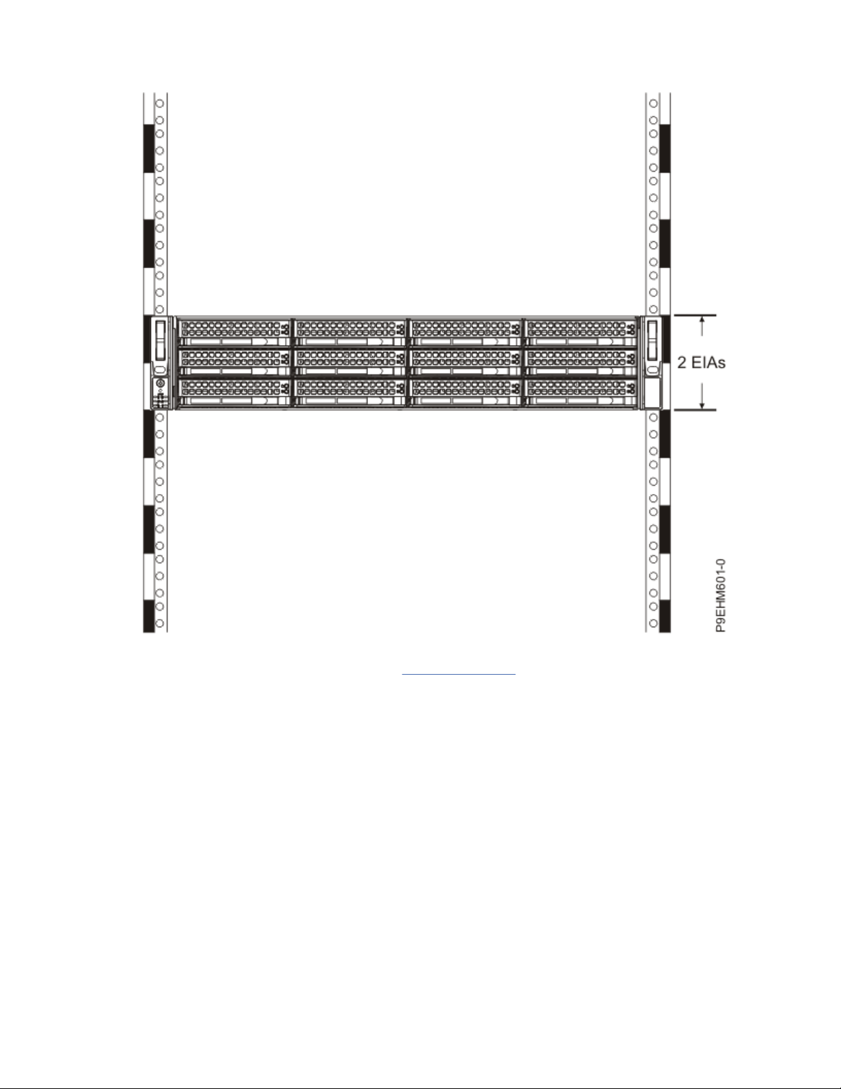
3. If necessary, remove the ller panels to allow access to the inside of the rack enclosure where you
plan to place the system unit, as shown in Figure 1 on page 4.
Installing and
conguring your system and system features 3
Page 18
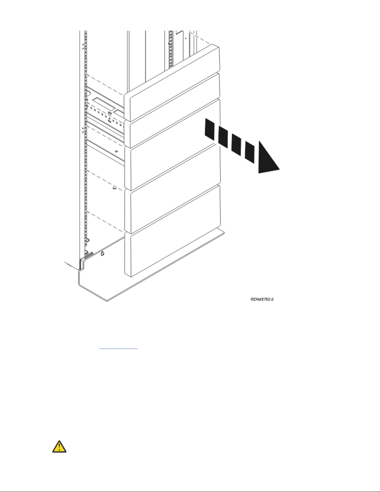
Figure 1. Removing the ller panels
4. Determine to place the system in the rack. Record the EIA location.
5. Facing the front of the rack and working from the right side, use tape, a marker, or pencil to mark the
lower hole of each EIA unit.
6. Repeat step “5” on page 4 for the corresponding holes located on the left side of the rack.
7. Go to the rear of the rack.
8. On the right side, nd the EIA unit that corresponds to the bottom EIA unit marked on the front of the
rack.
9. Mark the bottom EIA unit.
10. Mark the corresponding holes on the left side of the rack.
Attaching the rails to the rack and to the 5104-22C, 9006-22C, or 9006-22P system
You must install the rails onto the chassis and into the rack. Use this procedure to complete this task.
About this task
Attention:
have the correct rails and ttings for your rack. If your rack has square support flange holes or
4 Power Systems: Installing and conguring the IBM Power System LC922 (9006-22P)
To avoid rail failure and potential danger to yourself and to the unit, ensure that you
Page 19

screw-thread support flange holes, ensure that the rails and ttings match the support flange
holes that are used on your rack. Do not install mismatched hardware by using washers or spacers.
If you do not have the correct rails and ttings for your rack, contact your IBM reseller.
Note: The system requires 2 EIA rack units (2U) of space.
Procedure
1. If you are installing the system into a rack that has round holes, you must install hardware onto the
rails. The four hole adapters in the rail kit allow the rails to be attached to racks with round holes on
the flanges. To install the hole adapters, complete the following tasks:
a. Attach the adapters to the rails. The adapters slide and snap into place on the rail.
Note: Each adapter is marked with either an A or a B. For the left rail, the A bracket should be in
front, and the B bracket should be in back. For the right rail, the B bracket should be in front, and
the A bracket should be in back.
b. Remove the screw from each adapter.
c. Continue with step “5” on page 7.
2. Select the appropriate EIA location unit number for the rails. Each EIA location contains three holes
for mounting hardware.
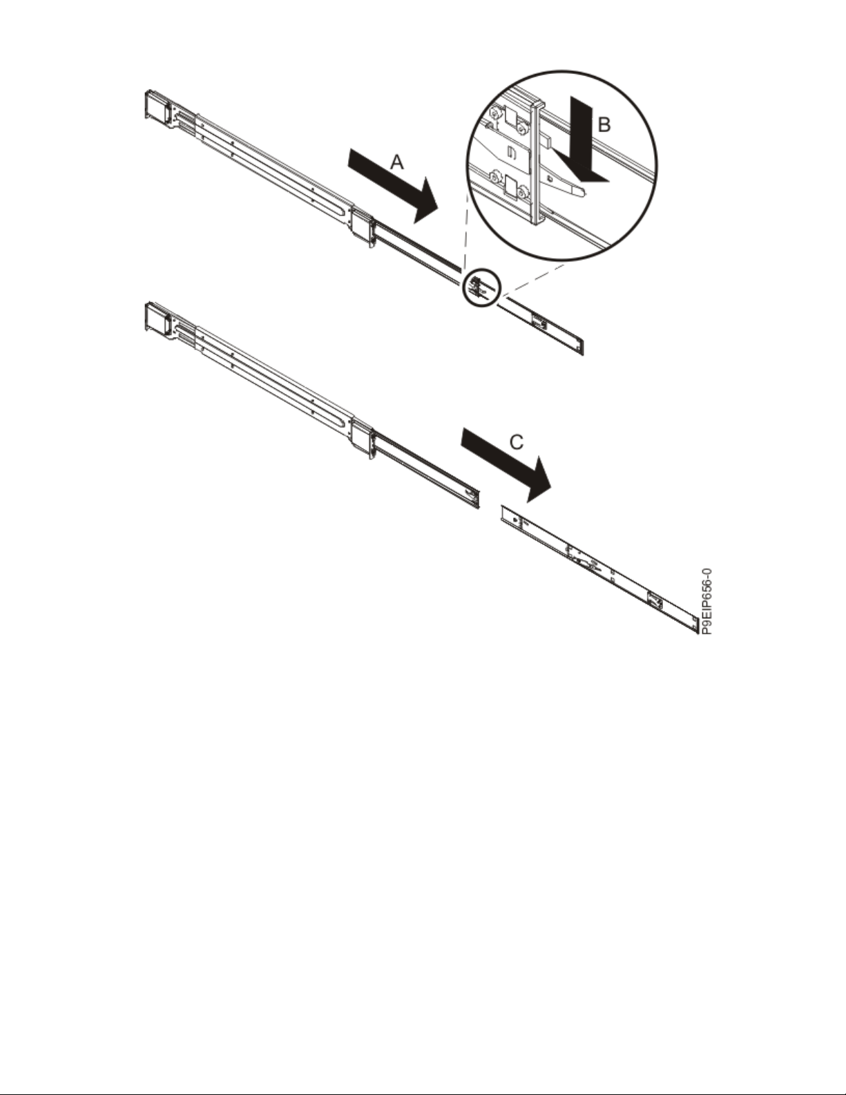
3. Each rail has two parts. Before you install the rails into the rack, you must separate them. To separate
the rails, extend the inner rail (A) and press the locking tab on the inner rail (B). Separate the inner
rail from the outer rail (C). Complete this task for each rail.
Installing and conguring your system and system features 5
Page 20
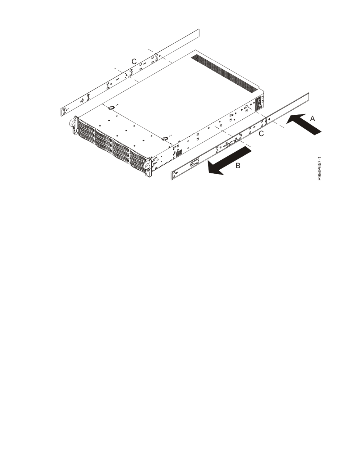
4. Attach the inner rails to the system chassis. To attach the inner rails to the system chassis, complete
the following tasks:
Note: Each inner rail is marked with either an L or an R, which designates the left inner rail and the
right inner rail. The front of the system is also marked L or an R behind each handle.
a. On the right side of the system, align the metal tabs on the system chassis with the holes on the
inner chassis slide rail (A). Slide the chassis slide rail toward the front of the rack (B) until the
chassis slide rail clicks into place. Secure the inner chassis slide rail to the system chassis by using
two screws (C).
b. Repeat this step for the left chassis slide rail.
6
Power Systems: Installing and conguring the IBM Power System LC922 (9006-22P)
Page 21
5. Move to the front of the rack. Align the left rack rail inside the rack cabinet by resting the rail bracket
hooks on the rack flange holes that you previously marked. The rail hooks are located in the flange
hole in the middle of each EIA rack unit.
6. With the rail bracket hooks resting on the rack flange holes, press down on the rack rails until the rail
pins click into place.
7. Repeat these steps for the right rack rail.
8. Move to the rear of the rack. Extend the left rack rail inside the rack cabinet until it hooks the rack
flange holes that you previously marked.
9. Press down on the rack rails until the rail pins click into place.
10. Repeat these steps for the right rack rail.
11. Move to the front of the rack. Secure the rails to the rack by fastening one screw through each hole in
each rail and through the EIA support flange.
Installing the 5104-22C, 9006-22C, or 9006-22P system into the rack and connecting and
routing power cables
After you install the system onto the rails in the rack, connect and route power cables.
About this task
Note: This system requires three people to install the system into the rack.
Procedure
1. Remove the protective plastic lm from the top of the system chassis.
2. Move to the front of the rack.
3. Extend each rail until it clicks into the extended position.
4. Using three people, lift the system and align the system chassis rails on each side of the chassis with
the rack slide rails.
5. While one person is supporting the weight of the system, have the second person gently push the
system into the rack, until you hear each slide rail click into place.
6. Simultaneously depress the slide rail latches on each side of the slide rail and push the system
toward the rear of the rack until the system clicks into place.
Installing and
conguring your system and system features 7
Page 22
7. Secure the system to the rack by screwing a screw through the handles on each side of the front of
the system chassis.
8. Plug the power cords into the power supplies.
9. Attach all cables to the rear of the server.
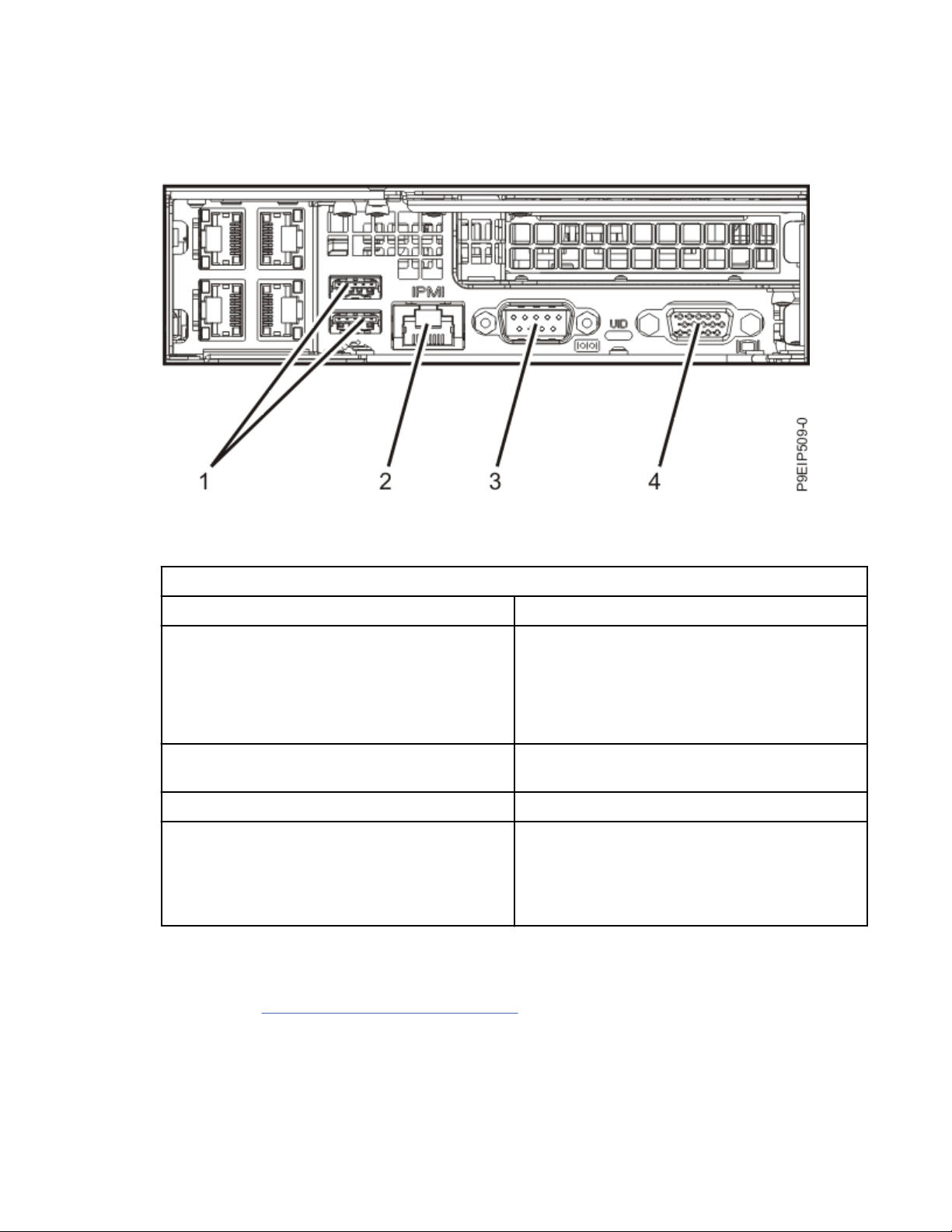
Figure 2. Rear ports
Table 1. Input and output ports
Identier Description
1 USB 2.0 used for keyboard and mouse.
Certain USB drives might be too wide to t
properly into the USB ports on the rear of the
system. Test the t of your USB drive before
proceeding.
2 Ethernet Intelligent Platform Management
Interface (IPMI)
3 Serial IPMI
4 Video Graphics Array (VGA) used for monitor.
Only the 1024 x 768 at 60 Hz VGA setting is
supported. Only up to a 3-meter cable is
supported. Only text-based capability is
supported.
10. Plug the system power cords and the power cords for any other attached devices into the alternating
current (AC) power source.
11. Press and hold the power button until the system begins the power-on sequence.
12. Continue with “Completing server setup” on page 8.
Completing server setup
Learn how to set up your server.
Procedure
1. Connect your server to a VGA terminal and keyboard or a console.
8
Power Systems: Installing and conguring the IBM Power System LC922 (9006-22P)
Page 23

Only the 1024x768 at 60 Hz VGA setting is supported. Only up to a 3 meter cable is supported.
2. Go to Getting xes (http://www.ibm.com/support/knowledgecenter/POWER9/p9ei8/
p9ei8_xes_kickoff.htm) and update the system rmware with the most recent level of rmware.
3. You can receive important technical information and updates for specic IBM Support tools and
resources by subscribing to receive updates. To subscribe to receive updates, complete the following
steps:
a. Go to the IBM Support Portal.
b. Log in by using your IBM ID and password and click Sign in.
c. Click Support notications.
d. Click Browse for a product.
e. Select Power > Firmware, nd your machine type and model and click Subscribe.
f. Exit the Browse for a product screen.
g. Click Delivery preferences to set email preferences and click Submit.
h. Click Edit to select the types of documentation updates that you want to receive and click Submit.
4. You can install the Linux operating system on bare metal systems, or on non-virtualized systems. For
these systems, the operating system runs directly on the Open Power Abstraction Layer (OPAL)
rmware.
For more information about installing the Linux operating system on bare-metal systems, see
Installing Linux on bare-metal systems
liabw/liabwkickoff.htm).
(http://www.ibm.com/support/knowledgecenter/linuxonibm/
Installing storage drives in the 9006-22P system
Learn how to install storage drives in the IBM Power System LC922 (9006-22P) system.
About this task
You can install the following types of drives in the system:
• SATA drives connected to the SATA controller ports on the system backplane
• Disk on module (DOM) drives
• SAS drives connected to a SAS RAID adapter
• NVMe drives connected to an NVMe adapter
• 3.5-inch drives
• 2.5-inch drives by using an adapter
Drive installation options for the 9006-22P system
Find information about the drive installation options for the IBM Power System LC922 (9006-22P)
system.
Note: The ambient temperature must not be more than 35°C (95°F).
Table 2 on page 10 shows the allowed combinations of front SAS, SATA, and NVMe drives with the
standard drive backplane. Table 3 on page 11 shows the allowed combinations of front SAS, SATA, and
NVMe drives with the enhanced LSI drive backplane.
Installing and
conguring your system and system features 9
Page 24
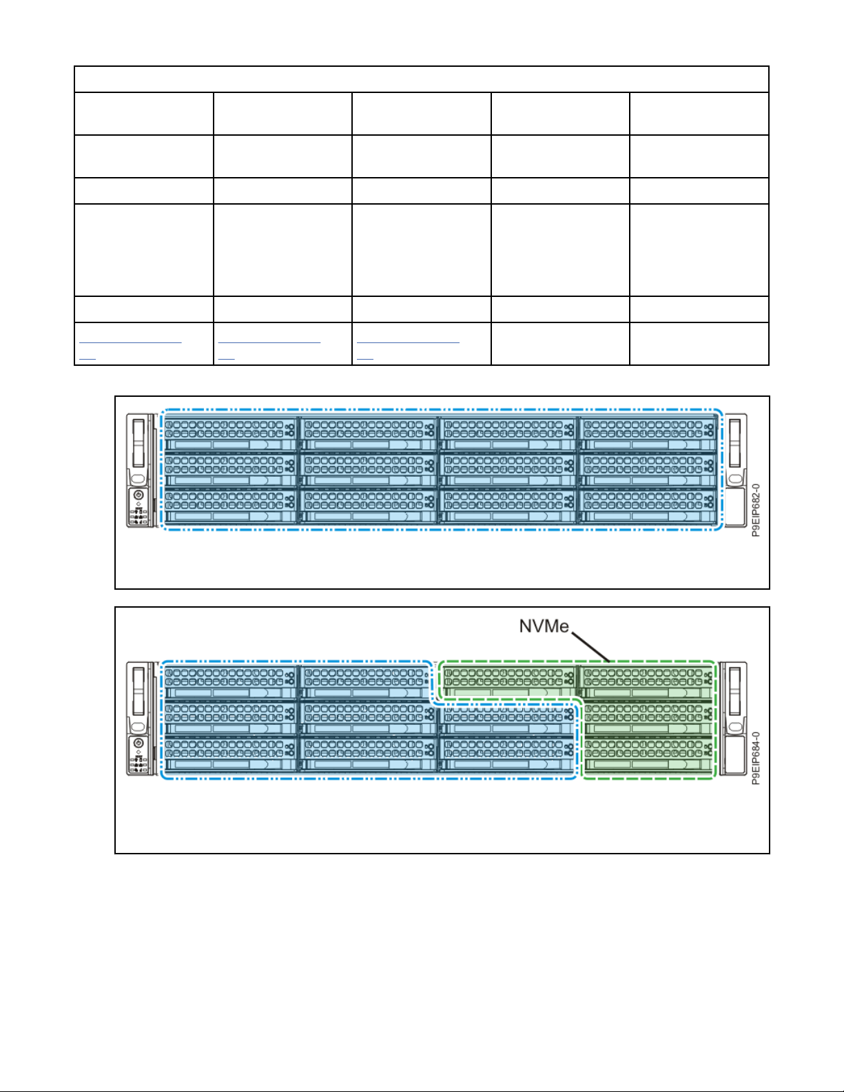
Table 2. Number of allowed front SAS, SATA, and NVMe drives with the standard drive backplane
Integrated
controller
0 NVMe drives 4 NVMe drives 0 NVMe drives 2 NVMe drives 4 NVMe drives
SAS/SATA drives SAS/SATA drives Four drives to
12 8 12 10 8
Figure 3 on page
10
Integrated
controller
NVMe adapter SAS/SATA adapter SAS/SATA adapter
Figure 4 on page
10
Integrated
controller
integrated
controller;
eight drives to SAS/
SATA adapter
Figure 5 on page
11
Integrated
controller
and NVMe adapter
Two drives to
integrated
controller;
eight drives to SAS/
SATA adapter
-
SAS/SATA adapter
and NVMe adapter
Eight drives to SAS/
SATA adapter
Figure 3. Up to 12 SAS or SATA drives, and up to two DOMs
Figure 4. Up to 8 SAS or SATA drives, or a mix of SAS HDDs and SATA SSDs (eight drives total), four NVMe
drives attached to an NVMe adapter, and up to two DOMs
10
Power Systems: Installing and conguring the IBM Power System LC922 (9006-22P)
Page 25
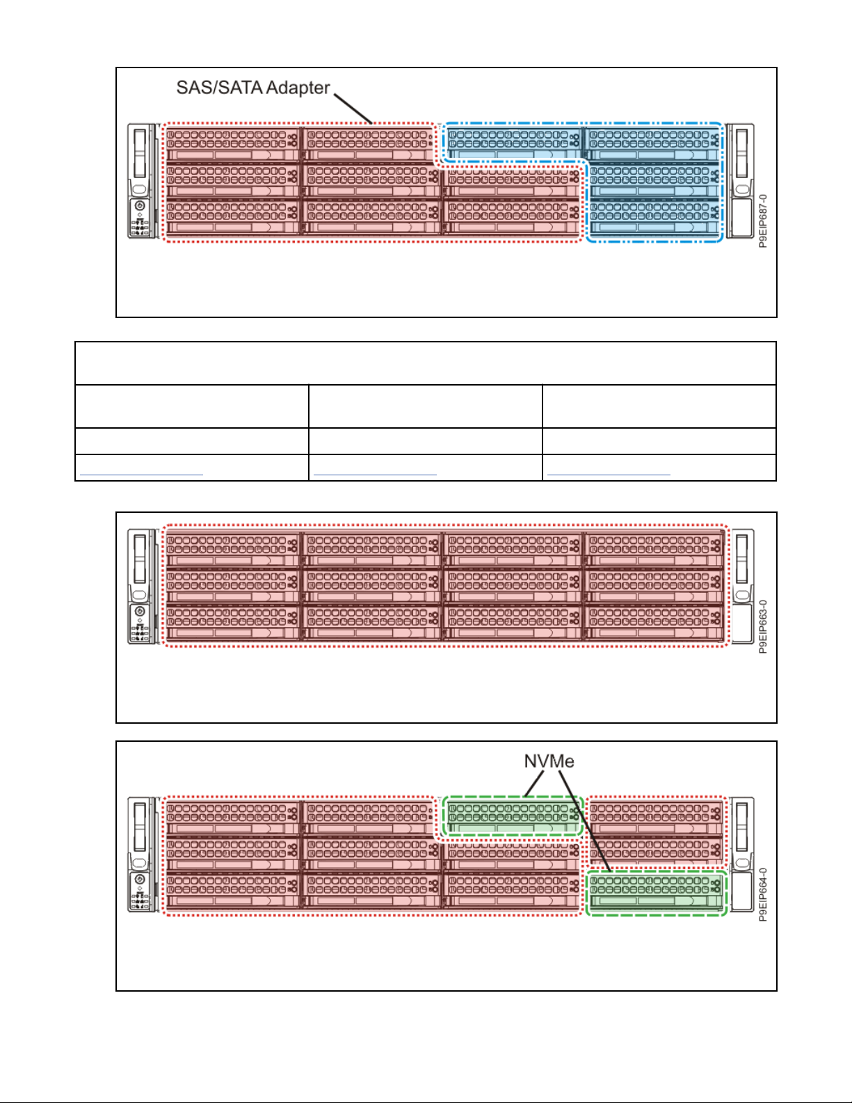
Figure 5. Up to eight SAS or SATA drives attached to a SAS/SATA adapter, up to four SAS or SATA drives
attached to integrated controller, and up to two DOMs
Table 3. Number of allowed front SAS/SATA drives with enhanced LSI drive backplane. The enhanced LSI drive
backplane requires a SAS/SATA adapter.
0 NVMe drives 2 NVMe drives and an NVMe
adaptor
12 10 8
Figure 6 on page 11 Figure 7 on page 11 Figure 8 on page 12
Figure 6. Up to 12 SAS or SATA drives, or a mix of SAS HDDs and SATA SSDs (12 drives total), SAS/SATA
adapter, and up to two DOMs
4 NVMe drives and an NVMe
adaptor
Figure 7. Up to 10 SAS or SATA drives, or a mix of SAS HDDs and SATA SSDs (10 drives total), SAS/SATA
adapter, two NVMe drives attached to an NVMe adapter, and up to two DOMs
Installing and
conguring your system and system features 11
Page 26
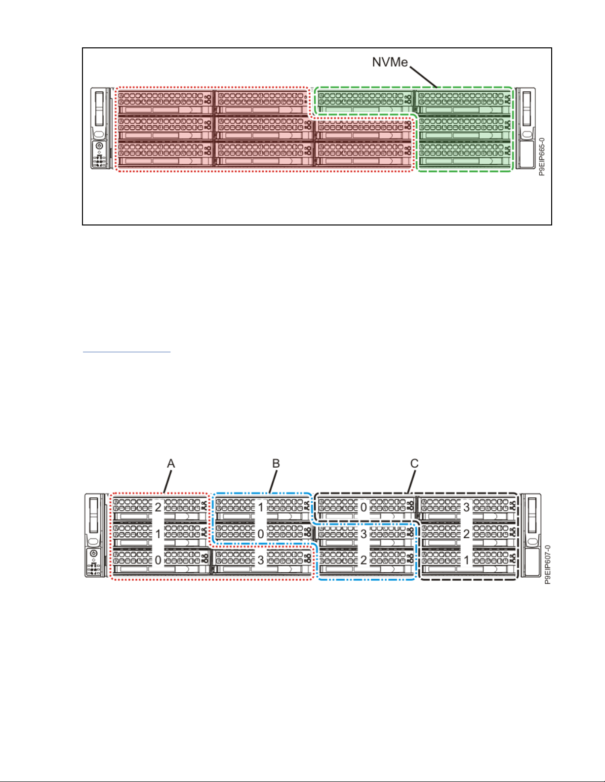
Figure 8. Up to eight SAS or SATA drives, or a mix of SAS HDDs and SATA SSDs (eight drives total), SAS/
SATA adapter, four NVMe drives attached to an NVMe adapter, and up to two DOMs
SATA Drives
The 9006-22C system with direct attach drive backplane can support up to 12 SATA drives. The drives are
directly connected to the SATA ports and to the controller on the system backplane. The SATA drives can
be installed into the front drive bay locations. SATA drive cables connect the disk drive backplane to the
SATA sockets on the system backplane.
You can plug SATA drive on module (DOM) drives directly into the system backplane. Use the two orange
SATA connectors. You can use up to two SATA DOM drives.
Figure 9 on page 12 shows the port to drive bay mapping for the disk drive backplane.
A
Maps to mini-SAS drive connector 1 and supports the indicated drive bays 0 through 3.
B
Maps to mini-SAS drive connector 2 and supports the indicated drive bays 0 through 3.
C
Maps to mini-SAS drive connector 3 and supports the indicated drive bays 0 through 3.
Figure 9. Port to drive bay mapping
SAS Drives
With the direct attach drive backplane and by using the system backplane controllers, the system can
support up to eight SATA/SAS drives with a maximum of four SATA drives. There are two SAS cables that
connect the disk drive backplane to the system backplane.
With the direct attach drive backplane and by using SAS/SATA RAID adapters, the system can support up
to twelve front SATA/SAS drives. If you are installing a RAID adapter, use three SAS cables to connect the
SAS ports on the PCIe adapter card to the SAS ports on the disk drive backplane.
12
Power Systems: Installing and conguring the IBM Power System LC922 (9006-22P)
Page 27
NVMe Enabled System and Drives
When the system has the NVMe drive backplane, the system supports both SATA/SAS and NVMe drives.
You can install up to twelve SATA/SAS drives using a SATA/SAS adapter. To support NVMe drives, you need
an NVMe adapter.
Four NVMe cables connect the disk drive backplane to the NVMe storage adapter.
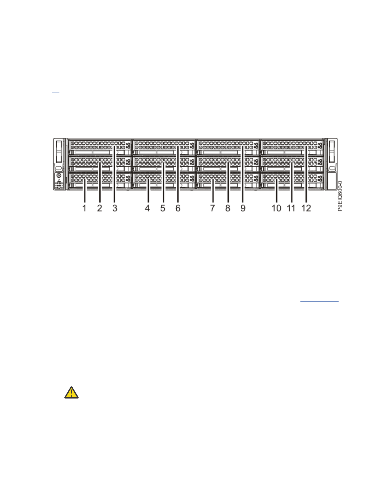
The rst two NVMe drives must be plugged into drive locations 9 and 10 as shown in Figure 10 on page
13. The second two NVMe drives must be plugged into locations 11 and 12.
NVMe drives are supported only on host operating systems. NVMe drives are not supported by guest
operating systems. On systems with RHEL 7.3 or later, or Ubuntu 16.04 or later, NVMe drives can be used
as bootable drives. Port 1 of the internal NVMe host bus adapter must be plugged into NVMe port 1 on the
disk drive backplane.
Figure 10. NVMe drives go in locations 9 through 12
.
Installing a front disk drive in the 9006-22P system
Learn how to install a disk drive in the front of the IBM Power System LC922 (9006-22P) system.
Before you begin
You can install SATA and SAS front drives with the system powered on and running.
When installing NVMe drives, the system needs to be powered down; for instructions, see “Stopping the
5104-22C, 9006-12P, 9006-22C, or 9006-22P system” on page 110.
About this task
Note: The ambient temperature must not be more than 35°C (95°F).
Procedure
1. Attach the electrostatic discharge (ESD) wrist strap.
The ESD wrist strap must be connected to an unpainted metal surface until the service procedure is
completed, and if applicable, until the service access cover is replaced.
Attention:
• Attach an electrostatic discharge (ESD) wrist strap to the front ESD jack, to the rear ESD jack,
or to an unpainted metal surface of your hardware to prevent the electrostatic discharge
from damaging your hardware.
• When you use an ESD wrist strap, follow all electrical safety procedures. An ESD wrist strap
is used for static control. It does not increase or decrease your risk of receiving electric
shock when using or working on electrical equipment.
Installing and conguring your system and system features 13
Page 28
• If you do not have an ESD wrist strap, just prior to removing the product from ESD packaging
and installing or replacing hardware, touch an unpainted metal surface of the system for a
minimum of 5 seconds. If at any point in this service process you move away from the
system, it is important to again discharge yourself by touching an unpainted metal surface
for at least 5 seconds before you continue with the service process.
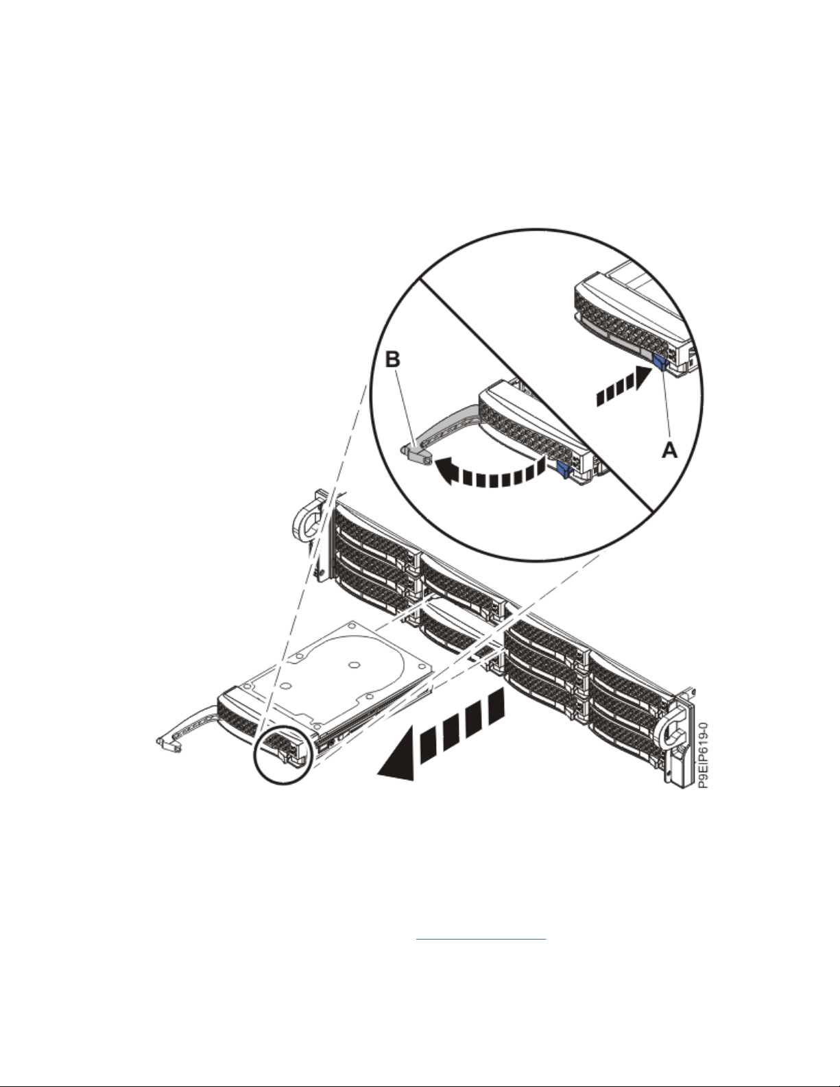
2. Unlock the drive bay handle (B) by pushing in the handle release (A) as shown in the following gure.
The handle (B) snaps out towards you. If the handle does not snap out all the way, the drive does not
slide out of the system.
Figure 11. Removing a front drive
3. If you are installing more than one drive, remove those drive trays.
4. For 3.5-inch drives, remove the plastic ller from the carrier. For 2.5-inch drives in a 3.5-inch
opening, a 2.5-inch tool-less drive carrier exists.
5. Install a drive into the tray.
Orient the drive such that the connectors are pointing to the rear of the drive.
• A 3.5-inch drive lls the tray, as shown in Figure 12 on page 15. Fasten the drive to the sides of
the tray with four screws (two screws on each side).
14
Power Systems: Installing and conguring the IBM Power System LC922 (9006-22P)
Page 29
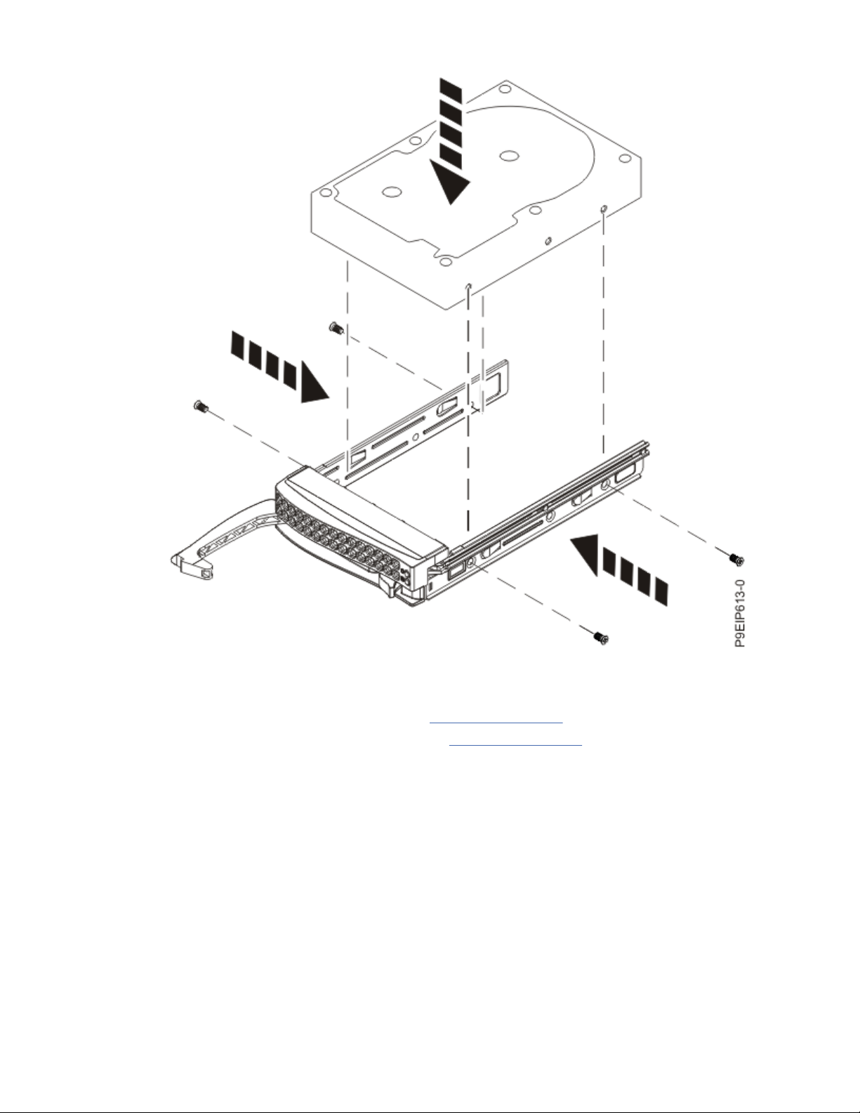
Figure 12. Mounting the 3.5-inch drive in the tray
• A 2.5-inch drive slides into the rear of the tool-less drive carrier.
a. Turn the tray upside down as shown in Figure 13 on page 16.
b. Open the retention spring (B) as shown in Figure 14 on page 17.
c. Place the 2.5-inch drive (A) into the tray, aligning the pins with the screw holes in the drive.
d. When the pins are aligned, close the retention spring, allowing the pins to secure the drive in
the tray.
e. Turn the tray right side up.
Installing and
conguring your system and system features 15
Page 30
Figure 13. Turning the 2.5-inch tray upside-down
16
Power Systems: Installing and conguring the IBM Power System LC922 (9006-22P)
Page 31

Figure 14. Mounting the 2.5-inch drive in the tray
6. Ensure that the drive handle is open. Support the drive by the bottom as you position the drive, and
insert it into the drive slot.
Ensure that the drive is fully seated and is all the way into the system.
7. Lock the drive bay handle (A) by pushing in the handle release until it locks at (B) as shown in Figure
15 on page 18.
Installing and
conguring your system and system features 17
Page 32

Figure 15. Disk drive lock detail
8. If you installed an NVMe drive, power the system back on.
For instructions, see “Starting the 5104-22C, 9006-12P, 9006-22C, or 9006-22P system ” on page
108.
9. For a non-RAID drive, congure the installed drive for your environment. If the drive is part of a RAID
conguration, skip this step, the drive is detected and congured when inserted.
After you insert the new drive, you need to rescan for the device.
Ubuntu Linux operating system
To run the rescan-scsi-bus command in the Ubuntu Linux operating system, log in to the
system as the root user, and run the following command:
rescan-scsi-bus
The rescan-scsi-bus tool is available in the scsitools package; install the package by using
the following command:
sudo apt-get install scsitools
18
Power Systems: Installing and conguring the IBM Power System LC922 (9006-22P)
Page 33

Red Hat Enterprise Linux (RHEL) version 7.2
To run the rescan command in the REHL version 7.2 operating system, log in to the system as the
root user, and run the following command:
rescan-scsi-bus.sh -a
The rescan-scsi-bus tool is available in the sg3_utils package; install the package by using the
following command:
yum install sg3_utils
You can also refer to: Adding a Storage Device or Path (https://access.redhat.com/
documentation/en-US/Red_Hat_Enterprise_Linux/7/html/Storage_Administration_Guide/logicalunit-add-remove.html).
10. Load or restore data from your backup media.
Installing a rear disk drive in the 9006-22P system
Learn how to install a disk drive in the rear of the IBM Power System LC922 (9006-22P) system.
Before you begin
Rear drives are an optional feature. You can install SATA and SAS rear drives with the system powered on
and running.
About this task
Procedure
1. Attach the electrostatic discharge (ESD) wrist strap.
The ESD wrist strap must be connected to an unpainted metal surface until the service procedure is
completed, and if applicable, until the service access cover is replaced.
Attention:
• Attach an electrostatic discharge (ESD) wrist strap to the front ESD jack, to the rear ESD jack,
or to an unpainted metal surface of your hardware to prevent the electrostatic discharge from
damaging your hardware.
• When you use an ESD wrist strap, follow all electrical safety procedures. An ESD wrist strap is
used for static control. It does not increase or decrease your risk of receiving electric shock
when using or working on electrical equipment.
• If you do not have an ESD wrist strap, just prior to removing the product from ESD packaging
and installing or replacing hardware, touch an unpainted metal surface of the system for a
minimum of 5 seconds. If at any point in this service process you move away from the system,
it is important to again discharge yourself by touching an unpainted metal surface for at least
5 seconds before you continue with the service process.
2. Unlock the drive bay handle (B) by pushing in the handle release (A) as shown in Figure 16 on page
20. The handle (B) snaps out towards you. If the handle does not snap out all the way, the drive does
not slide out of the system.
Installing and
conguring your system and system features 19
Page 34

Figure 16. Removing a rear drive
3. If you are installing more than one drive, remove the other drive tray.
4. Install a drive into the tray.
Ensure that the tray is open. Orient the drive such that the connectors are pointing to the rear of the
tray. Ensure that the screw holes (A) in the drive align with the pins (B) in the tray as shown in Figure
17 on page 21.
20
Power Systems: Installing and conguring the IBM Power System LC922 (9006-22P)
Page 35

Figure 17. Inserting the rear drive in the tray
5. While checking the alignment pins, press the sides (A) of the tray together until button (B) snaps into
place as shown in Figure 18 on page 22.
Installing and
conguring your system and system features 21
Page 36

Figure 18. Closing the rear drive tray
6. Ensure that the drive handle is open. Support the drive by the bottom as you position the drive, and
insert it into the drive slot.
Ensure that the drive is fully seated and is all the way into the system.
7. Lock the drive bay handle (A) by pushing in the handle release until it locks at (B) as shown in Figure
19 on page 23.
22
Power Systems: Installing and conguring the IBM Power System LC922 (9006-22P)
Page 37

Figure 19. Disk drive lock detail
8. For a non-RAID drive, congure the installed drive for your environment. If the drive is part of a RAID
conguration, skip this step, the drive is detected and congured when inserted.
After you insert the new drive, you need to rescan for the device.
Ubuntu Linux operating system
To run the rescan-scsi-bus command in the Ubuntu Linux operating system, log in to the
system as the root user, and run the following command:
rescan-scsi-bus
The rescan-scsi-bus tool is available in the scsitools package; install the package by using
the following command:
sudo apt-get install scsitools
Red Hat Enterprise Linux (RHEL) version 7.2
To run the rescan command in the REHL version 7.2 operating system, log in to the system as the
root user, and run the following command:
rescan-scsi-bus.sh -a
Installing and
conguring your system and system features 23
Page 38

The rescan-scsi-bus tool is available in the sg3_utils package; install the package by using the
following command:
yum install sg3_utils
You can also refer to: Adding a Storage Device or Path
documentation/en-US/Red_Hat_Enterprise_Linux/7/html/Storage_Administration_Guide/logicalunit-add-remove.html).
9. Load or restore data from your backup media.
Installing a drive on module in the 9006-22C system
Learn how to install a drive on module (DOM) in the IBM Power System LC922 (9006-22P) system.
Before you begin
Power off the system and place it in the service position. For instructions, see “Preparing the 5104-22C,
9006-22C, or 9006-22P system to remove and replace internal parts” on page 105.
About this task
You can plug SATA drive on module (DOM) drives directly into the system backplane. Up to two SATA DOM
drives can be installed. Use the two orange SATA connectors.
Procedure
1. Attach the electrostatic discharge (ESD) wrist strap.
The ESD wrist strap must be connected to an unpainted metal surface until the service procedure is
completed, and if applicable, until the service access cover is replaced.
Attention:
(https://access.redhat.com/
• Attach an electrostatic discharge (ESD) wrist strap to the front ESD jack, to the rear ESD jack,
or to an unpainted metal surface of your hardware to prevent the electrostatic discharge from
damaging your hardware.
• When you use an ESD wrist strap, follow all electrical safety procedures. An ESD wrist strap is
used for static control. It does not increase or decrease your risk of receiving electric shock
when using or working on electrical equipment.
• If you do not have an ESD wrist strap, just prior to removing the product from ESD packaging
and installing or replacing hardware, touch an unpainted metal surface of the system for a
minimum of 5 seconds. If at any point in this service process you move away from the system,
it is important to again discharge yourself by touching an unpainted metal surface for at least
5 seconds before you continue with the service process.
2. Install the DOM into the system backplane, in positions (A), as shown in Figure 20 on page 25.
Depending on the DOM model, you might also have to plug in a small power cord for the DOM. Ensure
that you plug in the connectors properly.
24
Power Systems: Installing and conguring the IBM Power System LC922 (9006-22P)
Page 39

Figure 20. Installing a DOM
3. Prepare the system for operation. For instructions, see “Preparing the 5104-22C, 9006-22C, or
9006-22P system for operation after you remove and replace internal parts” on page 107.
4. For a non-RAID drive, congure the installed drive for your environment. If the drive is part of a RAID
conguration, skip this step, the drive is detected and congured when inserted.
After you insert the new drive, you need to rescan for the device.
Ubuntu Linux operating system
To run the rescan-scsi-bus command in the Ubuntu Linux operating system, log in to the
system as the root user, and run the following command:
rescan-scsi-bus
The rescan-scsi-bus tool is available in the scsitools package; install the package by using
the following command:
sudo apt-get install scsitools
Red Hat Enterprise Linux (RHEL) version 7.2
To run the rescan command in the REHL version 7.2 operating system, log in to the system as the
root user, and run the following command:
rescan-scsi-bus.sh -a
Installing and
conguring your system and system features 25
Page 40

The rescan-scsi-bus tool is available in the sg3_utils package; install the package by using the
following command:
yum install sg3_utils
You can also refer to: Adding a Storage Device or Path
documentation/en-US/Red_Hat_Enterprise_Linux/7/html/Storage_Administration_Guide/logicalunit-add-remove.html).
5. Load or restore data from your backup media.
(https://access.redhat.com/
Installing memory in the 9006-22P system
Learn how to install memory in the IBM Power System LC922 (9006-22P) system.
Placement rules for memory in the 9006-12P or 9006-22P system
Learn about the congurations and rules that apply to adding memory to the IBM Power System LC921
(9006-12P) or IBM Power System LC922 (9006-22P) system.
• The system supports, 2, 4, 6, 8, 12, or 16 memory DIMMs (dual inline memory modules)
• The memory DIMMs can be 8, 16, 32, 64, or 128 GB
• For a single-processor system, the rst four DIMMs must be installed in a pairs. After the rst four
DIMMs, you must add memory DIMMs in quads.
• For a two-processor system, the rst eight DIMMs must be installed in a pairs. After the rst eight
DIMMS, you must add memory DIMMs in quads.
• Memory pairs must have the same size and type (A and B must match each other; C and D must match
each other).
• Memory pairs can have different memory sizes and types from other memory pairs (A and B do not need
to match C and D).
• The memory DIMMs must be added in a sequence.
• For a two-processor system, use Table 4 on page 26
memory placement.
• For a single-processor system, use Table 5 on page 27 and Figure 22 on page 28.
and Figure 21 on page 27 to determine the
Table 4. Two-processor memory plugging sequence
Slot Location Plugging Sequence
P1-A1 and P1-B1 1
P2-A1 and P2-B1 2
P1-C1 and P1-D1 3
P2-C1 and P2-D1 4
P1-A2, P1-B2, P1-C2, and P1-D2 5
P2-A2, P2-B2, P2-C2, and P2-D2 6
26 Power Systems: Installing and conguring the IBM Power System LC922 (9006-22P)
Page 41

Figure 21. Two-processor memory plugging sequence
Table 5. Single-processor memory plugging sequence
Slot Location Plugging Sequence
P1-A1 and P1-B1 1
P1-C1 and P1-D1 2
P1-A2, P1-B2, P1-C2, and P1-D2 3
Installing and conguring your system and system features 27
Page 42

Figure 22. Single-processor plugging sequence
Installing memory in the 9006-22P system
Learn how to install memory in the IBM Power System LC922 (9006-22P) system.
Before you begin
Power off the system and place it in the service position. For instructions, see “Preparing the 5104-22C,
9006-22C, or 9006-22P system to remove and replace internal parts” on page 105.
Procedure
1. Attach the electrostatic discharge (ESD) wrist strap.
The ESD wrist strap must be connected to an unpainted metal surface until the service procedure is
completed, and if applicable, until the service access cover is replaced.
Attention:
• Attach an electrostatic discharge (ESD) wrist strap to the front ESD jack, to the rear ESD jack,
or to an unpainted metal surface of your hardware to prevent the electrostatic discharge from
damaging your hardware.
• When you use an ESD wrist strap, follow all electrical safety procedures. An ESD wrist strap is
used for static control. It does not increase or decrease your risk of receiving electric shock
when using or working on electrical equipment.
• If you do not have an ESD wrist strap, just prior to removing the product from ESD packaging
and installing or replacing hardware, touch an unpainted metal surface of the system for a
minimum of 5 seconds. If at any point in this service process you move away from the system,
it is important to again discharge yourself by touching an unpainted metal surface for at least
5 seconds before you continue with the service process.
2. Determine the slot in which you want to install the memory. See “Placement rules for memory in the
9006-12P or 9006-22P system” on page 26 to understand the plugging rules and to ensure that you
plug the memory into the system in the correct sequence.
28
Power Systems: Installing and conguring the IBM Power System LC922 (9006-22P)
Page 43

3. Depending on the memory locations, you might need to remove the system processor air baffle.
Carefully unsnap and lift the processor air baffle from the system.
4. Push the DIMM locking tabs away from the socket.
5. Insert the memory DIMM.
a) Grasp the memory DIMM along its edges and align it with the slot on the system backplane.
Attention: Memory is keyed to prevent it from being installed incorrectly. Note the location
of the key tab within the memory connector before you attempt to install it.
b) Press rmly on each side of the memory DIMM as shown in Figure 23 on page 29 until the locking
tab locks in place with an audible click.
Figure 23. Inserting the memory DIMM
6. If you removed the system processor air baffle, replace it.
Insert the edge of the air baffle into the fan support. Then, carefully press the air baffle down into
place.
Installing and
conguring your system and system features 29
Page 44

What to do next
Prepare the system for operation. For instructions, see “Preparing the 5104-22C, 9006-22C, or 9006-22P
system for operation after you remove and replace internal parts” on page 107.
Installing a PCIe adapter in the 9006-22P system
Find information about how to install Peripheral Component Interconnect Express (PCIe) adapters into
the system.
About this task
Installing this feature is a customer task. You can complete this task yourself, or contact a service
provider to complete the task for you. You might be charged a fee by the service provider for this service.
The features listed in Table 6 on page 30 are electromagnetic compatibility (EMC) Class B features. See
the Class B Notices in the Hardware Notices section.
Table 6. Electromagnetic compatibility (EMC) Class B features for the 9006-22P system
Feature Description
EKA3 Intel 82575EB Dual-port Gigabit Ethernet Controller PCIe x4.0 LP; Adapter
part number: 01EM700 (AOC-SG-I2)
EKED Broadcom (LSI) 9300-8E SAS3 HBA PCIe3.0 x8 LP Adapter; Adapter part
number: 01EM634 (AOC-SAS3-9300-8E)
EKEH, see: EKAH Broadcom (LSI) MegaRAID 9361-8i SAS3 Controller with 8 internal ports (2 GB
Cache) PCIe3.0 x8 with cables; Adapter part number: 01EM632 (AOCK-9361-8I2S-IB001) and 01EM637 (AOC-K-9361-8I2B-IB001)
EKGC Broadcom (LSI) 9305-16E SAS3 HBA PCIe3.0 x8 LP; Adapter part number:
01EM701 (AOC-SAS3-9305-16E)
PCIe adapter placement rules and slot priorities for the 9006-22P system
Find information about the placement rules and slot priorities for the Peripheral Component Interconnect
Express (PCIe) adapters that are supported for the IBM Power System LC922 (9006-22P).
PCIe slot descriptions
The 9006-22P system provides PCIe generation 4 slots. Full-length, half-length or short (low-prole)
adapters can be installed. Figure 24 on page 30 shows the rear view of the system with the PCIe adapter
slots. Table 7 on page 31 lists the PCIe adapter slot locations and details for the 9006-22P system.
Figure 24. Rear view of a 9006-22P system with PCIe slots indicated
30
Power Systems: Installing and conguring the IBM Power System LC922 (9006-22P)
Page 45

Table 7. PCIe slot locations and descriptions for the 9006-22P system
Slot location CPU Connection Description Adapter size Coherent
Accelerator
Processor
Interface (CAPI)
1 (UIO Slot2) CPU1-PEC1 PCIe4 x8 Full-height, full-
length
2 (UIO Slot1) CPU1-PEC0 PCIe4 x16 Double-wide, full-
height, full-length
3 (WIO Slot1) CPU2-PEC0 PCIe4 x16 Double-wide, full-
height, full-length
4 (WIO-R Slot) CPU2-PEC1 PCIe4 x8 Half-height, half-
length
5 (WIO Slot2) CPU2-PEC2 PCIe4 x8 Full-height, full-
length
6 (WIO Slot3) CPU2-PEC2 PCIe4 x8 Full-height, full-
length
PCIe adapter placement rules
Use this information to select slots for installing PCIe adapters in the 9006-22P system. Table 8 on page
31 provides information about the adapters, the slot priorities in the system they are supported on, and
the maximum number of adapters that can be installed in the supported system. You can click the link
that appears in the feature code column for more technical information specic to the PCIe adapter.
Table 8. PCIe adapters supported in the 9006-22P system
No
Yes
Yes
No
No
Yes
Feature code Description 9006-22P (1 processor) 9006-22P (2 processors)
EKA1 Cavium (Qlogic)
BCM57840 PCIe3.0 x8
LP 4-port SFP+ 10 Gb
Ethernet adapter;
Adapter part number:
01EM699 (AOC-STGB4S)
EKA2 Intel 82599ES
Ethernet Converged
Network Adapter
x520-DA2 Dual-port
10G/1G SFP+ PCIe2.0
x8 LP; Adapter part
number: 01EM697
(AOC-STGN-I2S)
Slot priority Maximum
number of
adapters
supported
1, 2 2 4, 1, 5, 6, 3, 2 6
1, 2 2 4, 1, 5, 6, 3, 2 6
Slot priority Maximum
number of
adapters
supported
Installing and conguring your system and system features 31
Page 46

Table 8. PCIe adapters supported in the 9006-22P system (continued)
Feature code Description 9006-22P (1 processor) 9006-22P (2 processors)
EKA3 Intel 82575EB Dual-
port Gigabit Ethernet
Controller PCIe x4.0
LP; Adapter part
number: 01EM700
(AOC-SG-I2)
EKAF Emulex LPE16002B-
M6-O Dual-port 16 Gb
Fibre Channel Card
PCIe3.0 x8 LP; Adapter
part number: 01EM694
(AOC-LPE16002B-M6O)
EKAM Mellanox MCX415A-
CCAT ConnectX-4 EN
100 GbE Single-port
QSFP28 PCIe3.0 x16
LP; Adapter part
number: 01EM687
(AOC-MCX415A-CCATIB001)
Slot priority Maximum
number of
adapters
supported
1, 2 2 4, 1, 5, 6, 3, 2 6
1, 2 2 4, 1, 5, 6, 3, 2 6
2 1 2, 3, 1, 5, 6 5
Slot priority Maximum
number of
adapters
supported
EKAQ Qlogic QLE2692OP
Dual-port 16 Gb Fibre
Channel adapter PCIe3
x8 LP; Adapter part
number: 01EM692
(AOC-QLE2692SRIB001)
EKAU Mellanox MCX4121A-
ACAT ConnectX-4 Lx
EN 25 GbE Dual-port
SFP28 PCIe3.0 x8 LP;
Adapter part number:
01EM688 (AOCMCX4121A-ACATIB001)
EKAY Mellanox MCX556A-
EDAT ConnectX-5 VPI
EDR InniBand 100
Gb/s and 100 GbE
Dual-port QSFP28
PCIe4.0 x16 LP;
Adapter part number:
01EM691 (AOCMCX556A-EDATIB001)
1, 2 2 4, 1, 5, 6, 3, 2 6
1, 2 2 4, 1, 5, 6, 3, 2 6
2 1 2, 3, 1, 5, 6 5
32 Power Systems: Installing and conguring the IBM Power System LC922 (9006-22P)
Page 47

Table 8. PCIe adapters supported in the 9006-22P system (continued)
Feature code Description 9006-22P (1 processor) 9006-22P (2 processors)
EKEA Broadcom (LSI)
MegaRAID 9361-8i
SAS3 Controller with 8
Internal Ports (1 GB
Cache) PCIe3.0 x8 LP
with cables; Adapter
part number: 01EM631
(AOC-K-9361-8ISIB001) and 01EM636
(AOC-K-9361-8IBIB001)
EKEB SMC AOC-K-S3008L-
L8i 12 Gbps SAS3/
RAID 0,1 and 10
PCIe3.0 x8 LP with
cables; Adapter part
number: 01EM633
(AOC-SED-LSI00287)
and 01EM638 (AOC-KS3008L-L8iB-IB001)
Slot priority Maximum
number of
adapters
supported
1, 2 1 4, 1, 5, 6, 3, 2 2
1, 2 1 4, 1, 5, 6, 3, 2 2
Slot priority Maximum
number of
adapters
supported
EKED Broadcom (LSI)
9300-8E SAS3 HBA
PCIe3.0 x8 LP Adapter;
Adapter part number:
01EM634 (AOCSAS3-9300-8E)
EKEG SMC Quad-port NVMe
Host Bus Adapter
(PEX9733) PCIe3.0 x8
LP with cables;
Adapter part number:
01EM635 (AOC-KSLG3-4E2PS-IB001)
and 01EM639 (AOC-KSLG3-4E2PB-IB001)
EKEH Broadcom (LSI)
MegaRAID 9361-8i
SAS3 Controller with 8
internal ports (2 GB
Cache) PCIe3.0 x8 with
cables; Adapter part
number: 01EM632
(AOC-K-9361-8I2SIB001) and 01EM637
(AOC-K-9361-8I2BIB001)
1, 2 2 4, 1, 5, 6, 3, 2 6
1, 2 2 4, 1, 5, 6, 3, 2 2
1, 2 1 4, 1, 5, 6, 3, 2 2
Installing and conguring your system and system features 33
Page 48

Table 8. PCIe adapters supported in the 9006-22P system (continued)
Feature code Description 9006-22P (1 processor) 9006-22P (2 processors)
EKF1 Mellanox MCX414A-
BCAT ConnectX-4 EN
dual-port 40/56GbE
QFSP28 PCIe3.0 x8 LP
adapter; Adapter part
number: 01EM689
(AOC-MCX414A-BCATIB001)
EKFD Mellanox MCX555A-
ECAT ConnectX-5 VPI
EDR InniBand 100
Gb/s and 100 GbE
Single-port QSFP28
PCIe3.0 x16 LP;
Adapter part number:
01EM690 (AOCMCX555A-ECATIB001)
EKFE Qlogic QLE2742 32 Gb
Fibre Channel adapter
PCIe3 x8 2-port LP;
Adapter part number:
01EM693 (AOCQLE2742SR-IB001)
Slot priority Maximum
number of
adapters
supported
1, 2 2 4, 1, 5, 6, 3, 2 6
2 1 2, 3, 1, 5, 6 5
1, 2 2 4, 1, 5, 6, 3, 2 6
Slot priority Maximum
number of
adapters
supported
EKFF Broadcom 5719 QP 1G
(1G/100M/10M)
Network Interface
Card PCIe x4 LP;
Adapter part number:
01EM698 (AOCBCM5719-4P-BRC)
EKFH Intel XL710 Ethernet
Converged Network
Adapter Quad-port
10G/1G SFP+ PCIe3.0
x8 LP; Adapter part
number: 01EM695
(AOC-STG-i4S)
EKFP Intel XL710/X557
10GBase-T Converged
Network Adapter
Quad-port (10G/1G/
100M speeds) PCIe3.0
x8 LP; Adapter part
number: 01EM696
(AOC-STG-i4T)
1, 2 2 4, 1, 5, 6, 3, 2 6
1, 2 2 4, 1, 5, 6, 3, 2 6
1, 2 2 4, 1, 5, 6, 3, 2 6
34 Power Systems: Installing and conguring the IBM Power System LC922 (9006-22P)
Page 49

Table 8. PCIe adapters supported in the 9006-22P system (continued)
Feature code Description 9006-22P (1 processor) 9006-22P (2 processors)
EKGC Broadcom (LSI)
9305-16E SAS3 HBA
PCIe3.0 x8 LP; Adapter
part number: 01EM701
(AOC-SAS3-9305-16E)
EKSQ Samsung PM1725a
NVMe 1.6 TB 5DWPD
PCIe3.0 x8 LP Adapter;
Adapter part number:
01EM677 (HDS-AVTMZPLL1T6HEHP003)
EKSR Samsung PM1725a
NVMe 3.2 TB 5DWPD
PCIe3.0 x8 LP Adapter;
Adapter part number:
01EM678 (HDS-AVTMZPLL3T2HMLS003)
Slot priority Maximum
number of
adapters
supported
1, 2 2 4, 1, 5, 6, 3, 2 6
1, 2 2 4, 1, 5, 6, 3, 2 6
1, 2 2 4, 1, 5, 6, 3, 2 6
Slot priority Maximum
number of
adapters
supported
PCIe adapter information by feature type for the 9006-22P system
Find information about the Peripheral Component Interconnect Express (PCIe) adapters that are
supported for the IBM Power System LC922 (9006-22P).
The table shows the available adapters by feature code (FC), description, adapter FRU number, and
provides a link to more details for each adapter.
Important:
• This document does not replace the latest sales and marketing publications and tools that document
supported features.
• If you are installing a new feature, ensure that you have the software and utilities that are required to
support the new feature and determine whether you must install any adapter rmware updates. The
latest version of adapter rmware and utilities can be downloaded from Fix Central (http://
www.ibm.com/support/xcentral/).
• For more information regarding PCIe adapter identication and I/O rmware levels for each adapter, see
the IBM Power LC readme (https://www.ibm.com/developerworks/community/wikis/home?
lang=en_us#!/wiki/W51a7ffcf4dfd_4b40_9d82_446ebc23c550/page/IBM%20Power%20LC
%20readme).
Table 9. PCIe adapters supported in the 9006-22P system
Feature code Description
EKA1 Cavium (Qlogic) BCM57840 PCIe3.0 x8 LP 4-port SFP+ 10 Gb Ethernet adapter; Adapter
part number: 01EM699 (AOC-STG-B4S)
EKA2 Intel 82599ES Ethernet Converged Network Adapter x520-DA2 Dual-port 10G/1G SFP+
PCIe2.0 x8 LP; Adapter part number: 01EM697 (AOC-STGN-I2S)
Installing and conguring your system and system features 35
Page 50

Table 9. PCIe adapters supported in the 9006-22P system (continued)
Feature code Description
EKA3 Intel 82575EB Dual-port Gigabit Ethernet Controller PCIe x4.0 LP; Adapter part number:
01EM700 (AOC-SG-I2)
EKAF Emulex LPE16002B-M6-O Dual-port 16 Gb Fibre Channel Card PCIe3.0 x8 LP; Adapter part
number: 01EM694 (AOC-LPE16002B-M6-O)
EKAM Mellanox MCX415A-CCAT ConnectX-4 EN 100 GbE Single-port QSFP28 PCIe3.0 x16 LP;
Adapter part number: 01EM687 (AOC-MCX415A-CCAT-IB001)
EKAQ Qlogic QLE2692OP Dual-port 16 Gb Fibre Channel adapter PCIe3 x8 LP; Adapter part
number: 01EM692 (AOC-QLE2692SR-IB001)
EKAU Mellanox MCX4121A-ACAT ConnectX-4 Lx EN 25 GbE Dual-port SFP28 PCIe3.0 x8 LP;
Adapter part number: 01EM688 (AOC-MCX4121A-ACAT-IB001)
EKAY Mellanox MCX556A-EDAT ConnectX-5 VPI EDR InniBand 100 Gb/s and 100 GbE Dual-port
QSFP28 PCIe4.0 x16 LP; Adapter part number: 01EM691 (AOC-MCX556A-EDAT-IB001)
EKEA Broadcom (LSI) MegaRAID 9361-8i SAS3 Controller with 8 Internal Ports (1 GB Cache)
PCIe3.0 x8 LP with cables; Adapter part number: 01EM631 (AOC-K-9361-8IS-IB001) and
01EM636 (AOC-K-9361-8IB-IB001)
EKEB SMC AOC-K-S3008L-L8i 12 Gbps SAS3/RAID 0,1 and 10 PCIe3.0 x8 LP with cables; Adapter
part number: 01EM633 (AOC-SED-LSI00287) and 01EM638 (AOC-K-S3008L-L8iB-IB001)
EKED Broadcom (LSI) 9300-8E SAS3 HBA PCIe3.0 x8 LP Adapter; Adapter part number:
01EM634 (AOC-SAS3-9300-8E)
EKEG SMC Quad-port NVMe Host Bus Adapter (PEX9733) PCIe3.0 x8 LP with cables; Adapter part
number: 01EM635 (AOC-K-SLG3-4E2PS-IB001) and 01EM639 (AOC-K-SLG3-4E2PBIB001)
EKEH Broadcom (LSI) MegaRAID 9361-8i SAS3 Controller with 8 internal ports (2 GB Cache)
PCIe3.0 x8 with cables; Adapter part number: 01EM632 (AOC-K-9361-8I2S-IB001) and
01EM637 (AOC-K-9361-8I2B-IB001)
EKF1 Mellanox MCX414A-BCAT ConnectX-4 EN dual-port 40/56GbE QFSP28 PCIe3.0 x8 LP
adapter; Adapter part number: 01EM689 (AOC-MCX414A-BCAT-IB001)
EKFD Mellanox MCX555A-ECAT ConnectX-5 VPI EDR InniBand 100 Gb/s and 100 GbE Single-
port QSFP28 PCIe3.0 x16 LP; Adapter part number: 01EM690 (AOC-MCX555A-ECATIB001)
EKFE Qlogic QLE2742 32 Gb Fibre Channel adapter PCIe3 x8 2-port LP; Adapter part number:
01EM693 (AOC-QLE2742SR-IB001)
EKFF Broadcom 5719 QP 1G (1G/100M/10M) Network Interface Card PCIe x4 LP; Adapter part
number: 01EM698 (AOC-BCM5719-4P-BRC)
EKFH Intel XL710 Ethernet Converged Network Adapter Quad-port 10G/1G SFP+ PCIe3.0 x8 LP;
Adapter part number: 01EM695 (AOC-STG-i4S)
EKFP Intel XL710/X557 10GBase-T Converged Network Adapter Quad-port (10G/1G/100M
speeds) PCIe3.0 x8 LP; Adapter part number: 01EM696 (AOC-STG-i4T)
EKGC Broadcom (LSI) 9305-16E SAS3 HBA PCIe3.0 x8 LP; Adapter part number: 01EM701 (AOC-
SAS3-9305-16E)
EKSQ Samsung PM1725a NVMe 1.6 TB 5DWPD PCIe3.0 x8 LP Adapter; Adapter part number:
01EM677 (HDS-AVT-MZPLL1T6HEHP003)
36 Power Systems: Installing and conguring the IBM Power System LC922 (9006-22P)
Page 51

Table 9. PCIe adapters supported in the 9006-22P system (continued)
Feature code Description
EKSR Samsung PM1725a NVMe 3.2 TB 5DWPD PCIe3.0 x8 LP Adapter; Adapter part number:
01EM678 (HDS-AVT-MZPLL3T2HMLS003)
PCIe3 x4 Intel x550 10GBase-T Converged Network Adapter with Dual RJ45 Ports (FC EKA0)
Learn about the specications and operating system requirements for feature code (FC) EKA0 adapters.
Overview
The PCIe3 x4 Intel x550 10GBase-T Converged Network Adapter with Dual RJ45 Ports is a PCI Express
(PCIe) generation 3 (Gen3) x4 adapter. The adapter can be used in either a x8 or x16 PCIe slot in the
system. The adapter has an auto-negotiation feature 1 - 10 GbE that offers compatibility with earlier
versions for a smooth transition to 10 GbE.
Figure 25. PCIe3 x4 Intel x550 10GBase-T Converged Network Adapter with Dual RJ45 Ports
Installing and
conguring your system and system features 37
Page 52

Specications
Item
Description
Adapter FRU number
AOC-STGS-I2T (Designed to comply with RoHS requirement).
I/O bus architecture
PCIe3 x4.
Slot requirement
For more information about slot priorities, maximums, and placement rules, see the PCIe adapter
placement rules for the 9006-12P (http://www.ibm.com/support/knowledgecenter/POWER9/p9eip/
p9eip12p_pcie_slot_details.dita) or PCIe adapter placement rules for the 9006-22P (http://
www.ibm.com/support/knowledgecenter/POWER9/p9eip/p9eip22p_pcie_slot_details.dita).
Cables
RJ-45 Category-6 up to 55 M.
Voltage
3.3 V, 12 V.
Form factor
Short, low-prole.
Attributes provided
Direct Cache Access (DCA) to avoid cache misses.
TCP/UDP Segmentation offload.
Support for Virtual Machine Device Queues (VMDq and Next-generation VMDq).
Preboot eXecuation Environment (PXE) support.
Operating system or partition requirements
If you are installing a new feature, ensure that you have the software that is required to support the new
feature and that you determine whether any prerequisites must be met for this feature and attaching
devices. To check for operating system and partition requirements, see one of the following links:
• The latest version of enabling libraries and utilities can be downloaded from Fix Central
www.ibm.com/support/xcentral/).
• IBM Prerequisite website (www14.software.ibm.com/support/customercare/iprt/home).
• IBM SSIC (System Storage® Interoperation Center) (http://www-03.ibm.com/systems/support/storage/
ssic/interoperability.wss).
• The latest version of the device driver or the IBM Power RAID adapter utilities (iprutils) can be
downloaded from the IBM Service and Productivity Tools website (http://www14.software.ibm.com/
webapp/set2/sas/f/lopdiags/home.html).
• For more information, see the Linux Alert website (www14.software.ibm.com/webapp/set2/sas/f/
lopdiags/info/LinuxAlerts.html).
Cavium (Qlogic) BCM57840 PCIe3.0 x8 LP 4-port SFP+ 10 Gb Ethernet adapter (FC EKA1)
Learn about the specications and operating system requirements for the feature code (FC) EKA1 adapter.
Overview
The Cavium (Qlogic) BCM57840 PCIe3.0 x8 LP 4-port SFP+ 10 Gb Ethernet adapter is a PCI Express
(PCIe) generation 3 (Gen3) x8 adapter. The adapter can be used in either a x8 or x16 PCIe slot in the
system. The adapter offers a broad selection of networking features that include TCP offload, support for
PXE boot and virtualized environments (VMDq and PC-SIG SRIOV), and energy-efcient Ethernet (IEEE
802.3az).
(http://
38
Power Systems: Installing and conguring the IBM Power System LC922 (9006-22P)
Page 53

Figure 26. Cavium (Qlogic) BCM57840 PCIe3.0 x8 LP 4-port SFP+ 10 Gb Ethernet adapter
Specications
Item
Description
Adapter FRU number
01EM699 (AOC-STG-B4S) (Designed to comply with RoHS requirement).
I/O bus architecture
PCIe3 x8.
Slot requirement
For more information about slot priorities, maximums, and placement rules, see the PCIe adapter
placement rules for the 9006-12P (http://www.ibm.com/support/knowledgecenter/POWER9/p9eip/
p9eip12p_pcie_slot_details.dita) or PCIe adapter placement rules for the 9006-22P (http://
www.ibm.com/support/knowledgecenter/POWER9/p9eip/p9eip22p_pcie_slot_details.dita)
Voltage
3.3 V, 12 V.
Form factor
Short, low-prole.
Attributes provided
4 10Gb SFP+ ports.
TCP offload engine (TOE) for iSCSI and networking acceleration.
Installing and
conguring your system and system features 39
Page 54

IPv6 acceleration.
SR-IOV with up to 64 virtual functions (VFs) for guest operating systems (GOS) per port.
Transceivers and cables
FC EKC0: 3 M 10 Gb SFP+ SR Cable Fiber Active Optical Cable (AOC).
FC EKC1: 3 M 10 Gb SFP+ Copper Passive.
FC EKC2: 10/1 Gb SFP+ SR Optical Transceiver.
LC-LC ber-optic cables (with required optional transceivers).
Operating system or partition requirements
If you are installing a new feature, ensure that you have the software that is required to support the new
feature and that you determine whether any prerequisites must be met for this feature and attaching
devices. To check for operating system and partition requirements, see one of the following links:
• The latest version of enabling libraries and utilities can be downloaded from Fix Central (http://
www.ibm.com/support/xcentral/).
• IBM Prerequisite website (www14.software.ibm.com/support/customercare/iprt/home).
• IBM SSIC (System Storage Interoperation Center) (http://www-03.ibm.com/systems/support/storage/
ssic/interoperability.wss).
• The latest version of the device driver or the IBM Power RAID adapter utilities (iprutils) can be
downloaded from the IBM Service and Productivity Tools website
webapp/set2/sas/f/lopdiags/home.html).
• For more information, see the Linux Alert website (www14.software.ibm.com/webapp/set2/sas/f/
lopdiags/info/LinuxAlerts.html).
(http://www14.software.ibm.com/
Intel 82599ES Ethernet Converged Network Adapter x520-DA2 Dual-port 10G/1G SFP+ PCIe2.0 x8 LP (FC EKA2)
Learn about the specications and operating system requirements for the feature code (FC) EKA2 adapter.
Overview
The Intel 82599ES Ethernet Converged Network Adapter x520-DA2 Dual-port 10G/1G SFP+ PCIe2.0 x8
LP is a PCI Express (PCIe) generation 2 (Gen2) x8 adapter. The adapter can be used in either a x8 or x16
PCIe slot in the system. The adapter offers a broad selection of features including iSCSI remote boot
support, load balancing on multiple CPUs, and Fibre Channel over Ethernet (FCoE) support.
40
Power Systems: Installing and conguring the IBM Power System LC922 (9006-22P)
Page 55

Figure 27. IIntel 82599ES Ethernet Converged Network Adapter x520-DA2 Dual-port 10G/1G SFP+ PCIe2.0
x8 LP
Specications
Item
Description
Adapter FRU number
01EM697 (AOC-STGN-I2S) (Designed to comply with RoHS requirement)
I/O bus architecture
PCIe2 x8
Slot requirement
For more information about slot priorities, maximums, and placement rules, see the PCIe adapter
placement rules for the 9006-12P (http://www.ibm.com/support/knowledgecenter/POWER9/p9eip/
p9eip12p_pcie_slot_details.dita) or PCIe adapter placement rules for the 9006-22P (http://
www.ibm.com/support/knowledgecenter/POWER9/p9eip/p9eip22p_pcie_slot_details.dita)
Voltage
3.3V, 12 V.
Form factor
Short, low-prole.
Attributes provided
Preboot eXecution Environment (PXE) support.
Direct Cache Access (DCA) to avoid cache misses.
IPv6 offloading.
VMDq, Next-generation VMDq (64 queues per port) and PC-SIG SR-IOV implementation.
Installing and
conguring your system and system features 41
Page 56

Transceivers and cables
FC EKC0: 3 M 10 Gb SFP+ SR Cable Fiber Active Optical Cable (AOC)
FC EKC1: 3 M 10 Gb SFP+ Copper Passive
FC EKC2: 10/1 Gb SFP+ SR Optical Transceiver
Operating system or partition requirements
If you are installing a new feature, ensure that you have the software that is required to support the new
feature and that you determine whether any prerequisites must be met for this feature and attaching
devices. To check for operating system and partition requirements, see one of the following links:
• The latest version of enabling libraries and utilities can be downloaded from Fix Central (http://
www.ibm.com/support/xcentral/).
• IBM Prerequisite website (www14.software.ibm.com/support/customercare/iprt/home).
• IBM SSIC (System Storage Interoperation Center) (http://www-03.ibm.com/systems/support/storage/
ssic/interoperability.wss).
• The latest version of the device driver or the IBM Power RAID adapter utilities (iprutils) can be
downloaded from the IBM Service and Productivity Tools website (http://www14.software.ibm.com/
webapp/set2/sas/f/lopdiags/home.html).
• For more information, see the Linux Alert website
lopdiags/info/LinuxAlerts.html).
(www14.software.ibm.com/webapp/set2/sas/f/
Intel 82575EB Dual-port Gigabit Ethernet Controller PCIe x4.0 LP (FC EKA3)
Learn about the specications and operating system requirements for feature code (FC) EKA3 adapters.
Overview
The Intel 82575EB Dual-port Gigabit Ethernet Controller PCIe x4.0 LP is a PCI Express (PCIe) generation
2 (Gen2) x4 adapter. The adapter can be used in either an x8 or x16 PCIe slot in the system. The adapter
offers a high-performing PCIe 10/100/1000 Ethernet connection. It also improves flexibility and
performance in a virtualized environment in multi-core systems by lowering interrupt overhead and
providing sorted multiple data queue paths.
42
Power Systems: Installing and conguring the IBM Power System LC922 (9006-22P)
Page 57

Figure 28. IIntel 82575EB Dual-port Gigabit Ethernet Controller PCIe x4.0 LP
Specications
Item
Description
Adapter FRU number
01EM700 (AOC-SG-I2) (Designed to comply with RoHS requirement)
I/O bus architecture
PCIe2 x4.
Slot requirement
For more information about slot priorities, maximums, and placement rules, see the PCIe adapter
placement rules for the 9006-12P (http://www.ibm.com/support/knowledgecenter/POWER9/p9eip/
p9eip12p_pcie_slot_details.dita) or PCIe adapter placement rules for the 9006-22P (http://
www.ibm.com/support/knowledgecenter/POWER9/p9eip/p9eip22p_pcie_slot_details.dita).
Voltage
3.3 V, 12 V.
Attributes provided
Preboot eXecution Environment (PXE) support.
Intel I/O Acceleration Technology (I/O AT).
Direct Cache Access (DCA).
Low-latency interrupts.
Installing and
conguring your system and system features 43
Page 58

Transceivers and cables
Supported cable length is more than 100 M.
Operating system or partition requirements
If you are installing a new feature, ensure that you have the software that is required to support the new
feature and that you determine whether any prerequisites must be met for this feature and attaching
devices. To check for operating system and partition requirements, see one of the following links:
• The latest version of enabling libraries and utilities can be downloaded from Fix Central (http://
www.ibm.com/support/xcentral/).
• IBM Prerequisite website (www14.software.ibm.com/support/customercare/iprt/home).
• IBM SSIC (System Storage Interoperation Center) (http://www-03.ibm.com/systems/support/storage/
ssic/interoperability.wss).
• The latest version of the device driver or the IBM Power RAID adapter utilities (iprutils) can be
downloaded from the IBM Service and Productivity Tools website (http://www14.software.ibm.com/
webapp/set2/sas/f/lopdiags/home.html).
• For more information, see the Linux Alert website (www14.software.ibm.com/webapp/set2/sas/f/
lopdiags/info/LinuxAlerts.html).
Broadcom (LSI) MegaRAID 9361-8i SAS3 Controller with 8 Internal Ports (1 GB Cache) PCIe3.0 x8 LP with cables (FC EKAA and EKEA)
Learn about the specications and operating system requirements for feature code (FC) EKAA and EKEA
adapters.
Overview
The Broadcom (LSI) MegaRAID 9361-8i SAS3 Controller with 8 Internal Ports (1 GB Cache) PCIe3.0 x8 LP
with cables is a PCI Express (PCIe) generation 3 (Gen3) x8 adapter. The adapter can be used in either a x8
or x16 PCIe slot in the system. The adapter features 8 internal SAS connectors for high-performance
storage connectivity. This Redundant Array of Independent Disks (RAID) adapter is built on the LSI Logic
SAS IC and MegaRAID technology. It also supports high capacity storage applications by using highperformance RAID architecture, including hardware RAID 5 and 6.
Important: RAID mode is the adapter default and needs to be congured by the customer before drives
are shown to the operating system for installation. For instructions, see “StorCLI commands” on page
111.
Note: This adapter requires an additional PCIe slot to mount the CacheVault supercapacitor.
44
Power Systems: Installing and conguring the IBM Power System LC922 (9006-22P)
Page 59

Figure 29. Broadcom (LSI) MegaRAID 9361-8i SAS3 Controller with 8 Internal Ports (1 GB Cache) PCIe3.0
x8 LP with cables
Specications
Item
Description
Adapter FRU number
FC EKAA: 01EM631 (AOC-K-9361-8IS-IB001) (Designed to comply with RoHS requirement)
FC EKEA: 01EM636 (AOC-K-9361-8IB-IB001) (Designed to comply with RoHS requirement)
I/O bus architecture
PCIe3 x8
Slot requirement
For more information about slot priorities, maximums, and placement rules, see the PCIe adapter
placement rules for the 9006-12P (http://www.ibm.com/support/knowledgecenter/POWER9/p9eip/
p9eip12p_pcie_slot_details.dita) or PCIe adapter placement rules for the 9006-22P (http://
www.ibm.com/support/knowledgecenter/POWER9/p9eip/p9eip22p_pcie_slot_details.dita).
Voltage
3.3 V, 12 V.
Installing and
conguring your system and system features 45
Page 60

Form factor
Short, low-prole.
Attributes provided
Port-independent auto-negotiation.
Automatically negotiates PCIe link widths.
Supports 1.5, 3.0, 6.0 and 12 Gb/s SAS and SATA data transfer rates.
Advanced array conguration and management utilities.
Operating system or partition requirements
If you are installing a new feature, ensure that you have the software that is required to support the new
feature and that you determine whether any prerequisites must be met for this feature and attaching
devices. To check for operating system and partition requirements, see one of the following links:
• The latest version of enabling libraries and utilities can be downloaded from Fix Central (http://
www.ibm.com/support/xcentral/).
• IBM Prerequisite website (www14.software.ibm.com/support/customercare/iprt/home).
• IBM SSIC (System Storage Interoperation Center) (http://www-03.ibm.com/systems/support/storage/
ssic/interoperability.wss).
• The latest version of the device driver or the IBM Power RAID adapter utilities (iprutils) can be
downloaded from the IBM Service and Productivity Tools website
webapp/set2/sas/f/lopdiags/home.html).
• For more information, see the Linux Alert website (www14.software.ibm.com/webapp/set2/sas/f/
lopdiags/info/LinuxAlerts.html).
(http://www14.software.ibm.com/
Important: For a list of known Linux operating system issues that might affect this adapter, see the IBM
Power LC readme (https://ibm.biz/BdrgTZ).
SMC AOC-K-S3008L-L8i 12 Gbps SAS3/RAID 0,1 and 10 PCIe3.0 x8 LP with cables (FC EKAB and EKEB)
Learn about the specications and operating system requirements for feature code (FC) EKAB and EKEB
adapters.
Overview
The SMC AOC-K-S3008L-L8i 12 Gbps SAS3/RAID 0,1 and 10 PCIe3.0 x8 LP with cables is a PCI Express
(PCIe) generation 3 (Gen3) x8 adapter. The adapter can be placed in either a x8 or x16 PCIe slot in the
system. The 12 Gb/s 8-Port SAS Internal RAID Adapter features 8 internal SAS connectors for highperformance storage connectivity.
46
Power Systems: Installing and conguring the IBM Power System LC922 (9006-22P)
Page 61

Figure 30. SMC AOC-K-S3008L-L8i 12 Gbps SAS3/RAID 0,1 and 10 PCIe3.0 x8 LP with cables
Specications
Item
Description
Adapter FRU number
FC EKAB: 01EM633 (AOC-SED-LSI00287) (Designed to comply with RoHS requirement)
FC EKEB: 01EM638 (AOC-K-S3008L-L8iB-IB001) (Designed to comply with RoHS requirement)
I/O bus architecture
PCIe3 x8
Slot requirement
For more information about slot priorities, maximums, and placement rules, see the PCIe adapter
placement rules for the 9006-12P (http://www.ibm.com/support/knowledgecenter/POWER9/p9eip/
p9eip12p_pcie_slot_details.dita) or PCIe adapter placement rules for the 9006-22P (http://
www.ibm.com/support/knowledgecenter/POWER9/p9eip/p9eip22p_pcie_slot_details.dita)
Voltage
3.3 V, 12 V.
Form factor
Short, low-prole.
Attributes provided
Port-independent auto-negotiation.
Supports MegaRAID Storage Manager software.
Supports 3.0, 6.0 and 12 Gb/s SAS and SATA data transfer rates.
Installing and
conguring your system and system features 47
Page 62

Supports SSP, SMP, STP, and SATA protocols.
Operating system or partition requirements
If you are installing a new feature, ensure that you have the software that is required to support the new
feature and that you determine whether any prerequisites must be met for this feature and attaching
devices. To check for operating system and partition requirements, see one of the following links:
• The latest version of enabling libraries and utilities can be downloaded from Fix Central (http://
www.ibm.com/support/xcentral/).
• IBM Prerequisite website (www14.software.ibm.com/support/customercare/iprt/home).
• IBM SSIC (System Storage Interoperation Center) (http://www-03.ibm.com/systems/support/storage/
ssic/interoperability.wss).
• The latest version of the device driver or the IBM Power RAID adapter utilities (iprutils) can be
downloaded from the IBM Service and Productivity Tools website (http://www14.software.ibm.com/
webapp/set2/sas/f/lopdiags/home.html).
• For more information, see the Linux Alert website (www14.software.ibm.com/webapp/set2/sas/f/
lopdiags/info/LinuxAlerts.html).
Important: For a list of known Linux operating system issues that can affect this adapter, see the IBM
Power LC readme (https://ibm.biz/BdrgTZ).
Emulex LPE16002B-M6-O Dual-port 16 Gb Fibre Channel Card PCIe3.0 x8 LP (FC EKAF)
Learn about the specications and operating system requirements for the feature code (FC) EKAF adapter.
Overview
The Emulex LPE16002B-M6-O Dual-port 16 Gb Fibre Channel Card PCIe3.0 x8 LP is a PCI Express (PCIe)
generation 3 (Gen3) x8 adapter. The adapter can be used in either a x8 or x16 PCIe slot in the system. The
adapter features auto-negotiation, LDAP support and has a data transfer rate of 14.025 Gb/s.
48
Power Systems: Installing and conguring the IBM Power System LC922 (9006-22P)
Page 63

Figure 31. Emulex LPE16002B-M6-O Dual-port 16 Gb Fibre Channel Card PCIe3.0 x8 LP
Specications
Item
Description
Adapter FRU number
01EM694 (AOC-LPE16002B-M6-O) (Designed to comply with RoHS requirement)
I/O bus architecture
PCIe3 x8
Slot requirement
For more information about slot priorities, maximums, and placement rules, see the PCIe adapter
placement rules for the 9006-12P (http://www.ibm.com/support/knowledgecenter/POWER9/p9eip/
p9eip12p_pcie_slot_details.dita) or PCIe adapter placement rules for the 9006-22P (http://
www.ibm.com/support/knowledgecenter/POWER9/p9eip/p9eip22p_pcie_slot_details.dita)
Voltage
3.3 V, 12 V.
Form factor
Short, low-prole.
Installing and
conguring your system and system features 49
Page 64

Attributes provided
Auto-negotiation.
LDAP support.
Data transfer rate of 14.025 Gb/s.
Operating system or partition requirements
If you are installing a new feature, ensure that you have the software that is required to support the new
feature and that you determine whether any prerequisites must be met for this feature and attaching
devices. To check for operating system and partition requirements, see one of the following links:
• The latest version of enabling libraries and utilities can be downloaded from Fix Central (http://
www.ibm.com/support/xcentral/).
• IBM Prerequisite website (www14.software.ibm.com/support/customercare/iprt/home).
• IBM SSIC (System Storage Interoperation Center) (http://www-03.ibm.com/systems/support/storage/
ssic/interoperability.wss).
• The latest version of the device driver or the IBM Power RAID adapter utilities (iprutils) can be
downloaded from the IBM Service and Productivity Tools website (http://www14.software.ibm.com/
webapp/set2/sas/f/lopdiags/home.html).
• For more information, see the Linux Alert website
lopdiags/info/LinuxAlerts.html).
Important: For a list of known Linux operating system issues that may affect this adapter, see the IBM
Power LC readme (https://ibm.biz/BdrgTZ).
(www14.software.ibm.com/webapp/set2/sas/f/
SMC Quad-port NVMe Host Bus Adapter (PEX9733) PCIe3.0 x8 LP with cables (FC EKAG and EKEG)
Learn about the specications and operating system requirements for feature code (FC) EKAG and EKEG
adapters.
Overview
FC EKAG and EKEG are both the same adapter with different feature codes. FC EKAG is supported only on
the 9006-12C. FC EKEG, alternatively, is supported only on the 9006-22C, and both include cables.
The SMC Quad-port NVMe Host Bus Adapter (PEX9733) PCIe3.0 x8 LP with cables is a PCI Express (PCIe)
generation 3 (Gen3) x8 adapter. The adapter can be used in either a x8 or x16 PCIe slot in the system. The
adapter features four internal NVMe connectors for high-performance storage connectivity. This host bus
adapter (HBA) card is built on the PLX9733 PCIe switch IC technology and proven NVMe technology.
50
Power Systems: Installing and conguring the IBM Power System LC922 (9006-22P)
Page 65

Figure 32. SMC Quad-port NVMe Host Bus Adapter (PEX9733) PCIe3.0 x8 LP with cables
Specications
Item
Description
Adapter FRU number
FC EKAG: 01EM635 (AOC-K-SLG3-4E2PS-IB001) (Designed to comply with RoHS requirement)
FC EKEG: 01EM639 (AOC-K-SLG3-4E2PB-IB001) (Designed to comply with RoHS requirement)
I/O bus architecture
PCIe3 x8
Slot requirement
For more information about slot priorities, maximums, and placement rules, see the PCIe adapter
placement rules for the 9006-12P (http://www.ibm.com/support/knowledgecenter/POWER9/p9eip/
Installing and
conguring your system and system features 51
Page 66

p9eip12p_pcie_slot_details.dita) or PCIe adapter placement rules for the 9006-22P (http://
www.ibm.com/support/knowledgecenter/POWER9/p9eip/p9eip22p_pcie_slot_details.dita)
Voltage
3.3 V, 12 V
Form factor
Short, low-prole
Attributes provided
Supports four physical NVMe devices
Pure host bus adapter (HBA)
Supports 3.0 Gb/s, 6.0 Gb/s, and 12 Gb/s SAS transfer rates
Operating system or partition requirements
If you are installing a new feature, ensure that you have the software that is required to support the new
feature and that you determine whether any prerequisites must be met for this feature and attaching
devices. To check for operating system and partition requirements, see one of the following links:
• The latest version of enabling libraries and utilities can be downloaded from Fix Central (http://
www.ibm.com/support/xcentral/).
• IBM Prerequisite website
• IBM SSIC (System Storage Interoperation Center) (http://www-03.ibm.com/systems/support/storage/
ssic/interoperability.wss).
• The latest version of the device driver or the IBM Power RAID adapter utilities (iprutils) can be
downloaded from the IBM Service and Productivity Tools website (http://www14.software.ibm.com/
webapp/set2/sas/f/lopdiags/home.html).
• For more information, see the Linux Alert website (www14.software.ibm.com/webapp/set2/sas/f/
lopdiags/info/LinuxAlerts.html).
(www14.software.ibm.com/support/customercare/iprt/home).
Important: For a list of known Linux operating system issues that can affect this adapter, see the IBM
Power LC readme (https://ibm.biz/BdrgTZ).
Broadcom (LSI) MegaRAID 9361-8i SAS3 Controller with 8 internal ports (2 GB Cache) PCIe3.0 x8 with cables (FC EKAH and EKEH)
Learn about the specications and operating system requirements for feature code (FC) EKAH and EKEH
adapters.
Overview
FC EKAH and EKEH are both the same adapter with different feature codes.
The Broadcom (LSI) MegaRAID 9361-8i SAS3 Controller with 8 internal ports (2 GB Cache) PCIe3.0 x8
with cables is a PCI Express (PCIe) generation 3 (Gen3) x8 adapter. The adapter can be used in either a x8
or x16 PCIe slot in the system. The adapter features 8 internal SAS connectors for high-performance
storage connectivity. This Redundant Array of Independent Disks (RAID) adapter is built on the LSI Logic
SAS IC and MegaRAID technology. It also supports high capacity storage applications using highperformance RAID architecture, including hardware RAID 5 and 6.
Important: RAID mode is the adapter default and needs to be congured by the customer before drives
are shown to the operating system for installation. For instructions, see “StorCLI commands” on page
111.
Note: This adapter requires an additional PCIe slot to mount the CacheVault supercapacitor.
52
Power Systems: Installing and conguring the IBM Power System LC922 (9006-22P)
Page 67

Figure 33. Broadcom (LSI) MegaRAID 9361-8i SAS3 Controller with 8 internal ports (2 GB Cache) PCIe3.0
x8 with cables
Specications
Item
Description
Adapter FRU number
FC EKAH: 01EM632 (AOC-K-9361-8I2S-IB001) (Designed to comply with RoHS requirement)
FC EKEH: 01EM637 (AOC-K-9361-8I2B-IB001) (Designed to comply with RoHS requirement)
I/O bus architecture
PCIe3 x8
Slot requirement
For more information about slot priorities, maximums, and placement rules, see the PCIe adapter
placement rules for the 9006-12P (http://www.ibm.com/support/knowledgecenter/POWER9/p9eip/
Installing and
conguring your system and system features 53
Page 68

p9eip12p_pcie_slot_details.dita) or PCIe adapter placement rules for the 9006-22P (http://
www.ibm.com/support/knowledgecenter/POWER9/p9eip/p9eip22p_pcie_slot_details.dita).
Voltage
3.3 V, 12 V.
Form factor
Short, low-prole.
Attributes provided
Port independent auto-negotiation.
Automatically negotiates PCIe link widths.
Supports 1.5, 3.0, 6.0 and 12 Gb/s SAS and SATA data transfer rates.
Advanced array conguration and management utilities.
Operating system or partition requirements
If you are installing a new feature, ensure that you have the software that is required to support the new
feature and that you determine whether any prerequisites must be met for this feature and attaching
devices. To check for operating system and partition requirements, see one of the following links:
• The latest version of enabling libraries and utilities can be downloaded from Fix Central
www.ibm.com/support/xcentral/).
• IBM Prerequisite website (www14.software.ibm.com/support/customercare/iprt/home).
• IBM SSIC (System Storage Interoperation Center) (http://www-03.ibm.com/systems/support/storage/
ssic/interoperability.wss).
• The latest version of the device driver or the IBM Power RAID adapter utilities (iprutils) can be
downloaded from the IBM Service and Productivity Tools website (http://www14.software.ibm.com/
webapp/set2/sas/f/lopdiags/home.html).
• For more information, see the Linux Alert website (www14.software.ibm.com/webapp/set2/sas/f/
lopdiags/info/LinuxAlerts.html).
Important: For a list of known Linux operating system issues that may affect this adapter, see the IBM
Power LC readme (https://ibm.biz/BdrgTZ).
Mellanox MCX456A-ECAT ConnectX-4 VPI EDR InniBand 100 Gb/s and 100 GbE Dual-port QSFP28
PCIe3.0 x16 LP Adapter (FC EKAL)
Learn about the specications and operating system requirements for the feature code (FC) EKAL adapter.
Overview
The Mellanox MCX456A-ECAT ConnectX-4 VPI EDR InniBand 100 Gb/s and 100 GbE Dual-port QSFP28
PCIe3.0 x16 LP Adapter is a PCI Express (PCIe) generation 3 (Gen3) x16 adapter. The adapter can be
used in either a x8 or x16 PCIe slot in the system. The adapter supports EDR 100 Gb/s InniBand and
100 Gb/s Ethernet connectivity. It also provides flexible solutions for high-performance, Web 2.0, cloud,
data analytics, database, and storage platforms.
(http://
54
Power Systems: Installing and conguring the IBM Power System LC922 (9006-22P)
Page 69

Figure 34. Mellanox MCX456A-ECAT ConnectX-4 VPI EDR InniBand 100 Gb/s and 100 GbE Dual-port
QSFP28 PCIe3.0 x16 LP Adapter
Specications
Item
Description
Adapter FRU number
AOC-MCX456A-ECAT-IB001 (Designed to comply with RoHS requirement)
I/O bus architecture
PCIe3 x16
Slot requirement
For more information about slot priorities, maximums, and placement rules, see the PCIe adapter
placement rules for the 9006-12P (http://www.ibm.com/support/knowledgecenter/POWER9/p9eip/
p9eip12p_pcie_slot_details.dita) or PCIe adapter placement rules for the 9006-22P (http://
www.ibm.com/support/knowledgecenter/POWER9/p9eip/p9eip22p_pcie_slot_details.dita)
Installing and
conguring your system and system features 55
Page 70

Voltage
3.3 V, 12 V.
Form factor
Short, with full-height tailstock
Attributes provided
EDR 100 Gb/s InniBand or 100 Gb/s Ethernet per port
Supports 2 physical NVMe Devices
Single and dual-port options available
Hardware-based I/O virtualization
Transceivers and cables
Mellanox LinkX 10, 25, 40, 50 and 100Gb/s Direct Attach Copper cables (DACs), Copper Splitter
cables, Active Optical Cables (AOCs) and Transceivers. For information regarding Mellanox LinkX
cables and transceivers, see LinkX™ InniBand Direct Attach Copper Cables (http://
www.mellanox.com/products/interconnect/inniband-copper-cables.php)
Operating system or partition requirements
If you are installing a new feature, ensure that you have the software that is required to support the new
feature and that you determine whether any prerequisites must be met for this feature and attaching
devices. To check for operating system and partition requirements, see one of the following links:
• The latest version of enabling libraries and utilities can be downloaded from Fix Central
www.ibm.com/support/xcentral/).
• IBM Prerequisite website (www14.software.ibm.com/support/customercare/iprt/home).
• IBM SSIC (System Storage Interoperation Center) (http://www-03.ibm.com/systems/support/storage/
ssic/interoperability.wss).
• The latest version of the device driver or the IBM Power RAID adapter utilities (iprutils) can be
downloaded from the IBM Service and Productivity Tools website (http://www14.software.ibm.com/
webapp/set2/sas/f/lopdiags/home.html).
• For more information, see the Linux Alert website (www14.software.ibm.com/webapp/set2/sas/f/
lopdiags/info/LinuxAlerts.html).
Mellanox MCX415A-CCAT ConnectX-4 EN 100GbE Single-port QSFP28 PCIe3.0 x16 LP Adapter (FC EKAM)
Learn about the specications and operating system requirements for the feature code (FC) EKAM
adapter.
Overview
The Mellanox MCX415A-CCAT ConnectX-4 EN 100GbE single-port QSFP28 PCIe3.0 x16 LP Adapter is a
PCI Express (PCIe) generation 3 (Gen3) x16 adapter. The adapter can be used in either a x8 or x16 PCIe
slot in the system. The adapter supports 100 Gb/s Ethernet per port and provides flexible solutions for
high-performance, Web 2.0, cloud, data analytics, database, and storage platforms.
(http://
56
Power Systems: Installing and conguring the IBM Power System LC922 (9006-22P)
Page 71

Figure 35. Mellanox MCX415A-CCAT ConnectX-4 EN 100 GbE Single-port QSFP28 PCIe3.0 x16 LP
Specications
Item
Description
Adapter FRU number
01EM687 (AOC-MCX415A-CCAT-IB001) (Designed to comply with RoHS requirement)
I/O bus architecture
PCIe3 x16
Slot requirement
For more information about slot priorities, maximums, and placement rules, see the PCIe adapter
placement rules for the 9006-12P (http://www.ibm.com/support/knowledgecenter/POWER9/p9eip/
p9eip12p_pcie_slot_details.dita) or PCIe adapter placement rules for the 9006-22P (http://
www.ibm.com/support/knowledgecenter/POWER9/p9eip/p9eip22p_pcie_slot_details.dita).
Installing and
conguring your system and system features 57
Page 72

Voltage
3.3 V, 12 V.
Form factor
Short, with full-height tailstock.
Attributes provided
EDR 100 Gb/s InniBand or 100 Gb/s Ethernet per port.
Supports two physical NVMe devices.
Single and dual-port options available.
Hardware-based I/O virtualization.
Transceivers and cables
Mellanox LinkX 10, 25, 40, 50 and 100Gb/s Direct Attach Copper cables (DACs), Copper Splitter
cables, Active Optical Cables (AOCs) and Transceivers. For information regarding Mellanox LinkX
cables and Transceivers, see LinkX™ InniBand Direct Attach Copper Cables(http://
www.mellanox.com/products/interconnect/inniband-copper-cables.php).
Operating system or partition requirements
If you are installing a new feature, ensure that you have the software that is required to support the new
feature and that you determine whether any prerequisites must be met for this feature and attaching
devices. To check for operating system and partition requirements, see one of the following links:
• The latest version of enabling libraries and utilities can be downloaded from Fix Central
www.ibm.com/support/xcentral/).
• IBM Prerequisite website (www14.software.ibm.com/support/customercare/iprt/home).
• IBM SSIC (System Storage Interoperation Center) (http://www-03.ibm.com/systems/support/storage/
ssic/interoperability.wss).
• The latest version of the device driver or the IBM Power RAID adapter utilities (iprutils) can be
downloaded from the IBM Service and Productivity Tools website (http://www14.software.ibm.com/
webapp/set2/sas/f/lopdiags/home.html).
• For more information, see the Linux Alert website (www14.software.ibm.com/webapp/set2/sas/f/
lopdiags/info/LinuxAlerts.html).
Important: For a list of known Linux operating system issues that can affect this adapter, see the IBM
Power LC readme (https://ibm.biz/BdrgTZ).
Mellanox MCX415A-CCAT ConnectX-4 EN 100 GbE Single-port QSFP28 PCIe3.0 x16 LP Adapter (FC EKAP)
Learn about the specications and operating system requirements for the feature code (FC) EKAP adapter.
Overview
The Mellanox MCX415A-CCAT ConnectX-4 EN 100 GbE Single-port QSFP28 PCIe3.0 x16 LP Adapter is a
PCI Express (PCIe) generation 3 (Gen2) x8 adapter. The adapter can be used in either a x8 or x16 PCIe
slot in the system. The adapter offers dual-channel performance, auto-negotiation and StarPower
technology.
(http://
58
Power Systems: Installing and conguring the IBM Power System LC922 (9006-22P)
Page 73

Figure 36. Mellanox MCX415A-CCAT ConnectX-4 EN 100 GbE Single-port QSFP28 PCIe3.0 x16 LP Adapter
Specications
Item
Description
Adapter FRU number
AOC-QLE2562 (Designed to comply with RoHS requirement)
I/O bus architecture
PCIe3 x8
Slot requirement
For more information about slot priorities, maximums, and placement rules, see the PCIe adapter
placement rules for the 9006-12P (http://www.ibm.com/support/knowledgecenter/POWER9/p9eip/
p9eip12p_pcie_slot_details.dita) or PCIe adapter placement rules for the 9006-22P (http://
www.ibm.com/support/knowledgecenter/POWER9/p9eip/p9eip22p_pcie_slot_details.dita)
Installing and
conguring your system and system features 59
Page 74

Voltage
3.3 V, 12 V.
Form factor
Short, low-prole
Attributes provided
StarPower technology
Auto-negotiation
Quality of Service (QoS)
Operating system or partition requirements
If you are installing a new feature, ensure that you have the software that is required to support the new
feature and that you determine whether any prerequisites must be met for this feature and attaching
devices. To check for operating system and partition requirements, see one of the following links:
• The latest version of enabling libraries and utilities can be downloaded from Fix Central (http://
www.ibm.com/support/xcentral/).
• IBM Prerequisite website (www14.software.ibm.com/support/customercare/iprt/home).
• IBM SSIC (System Storage Interoperation Center)
ssic/interoperability.wss).
• The latest version of the device driver or the IBM Power RAID adapter utilities (iprutils) can be
downloaded from the IBM Service and Productivity Tools website (http://www14.software.ibm.com/
webapp/set2/sas/f/lopdiags/home.html).
• For more information, see the Linux Alert website (www14.software.ibm.com/webapp/set2/sas/f/
lopdiags/info/LinuxAlerts.html).
(http://www-03.ibm.com/systems/support/storage/
Important: For a list of known Linux operating system issues that may affect this adapter, see the IBM
Power LC readme (https://ibm.biz/BdrgTZ).
Qlogic QLE2692OP Dual-port 16 Gb Fibre Channel adapter PCIe3 x8 LP (FC EKAQ)
Learn about the specications and operating system requirements for the feature code (FC) EKAQ
adapter.
Overview
The Qlogic QLE2692OP Dual-port 16 Gb Fibre Channel adapter PCIe3 x8 LP Adapter is a PCI Express
(PCIe) generation 3 (Gen3) x8 adapter. The adapter can be used in either a x8 or x16 PCIe slot in the
system. The adapter provides advanced storage networking features capable of supporting demanding
virtualized and private cloud environments. The PCIe3 x8 Qlogic QLE2692OP Dual-port 16Gb Fibre
Channel Adapter can also deliver up to 1.3 million IOPS (Input/Output Operations per Second) fuel high
performance in all-flash arrays (AFAs) and high-density virtualized environments.
Figure 37. Qlogic QLE2692OP Dual-port 16 Gb Fibre Channel adapter PCIe3 x8 LP Adapter
60
Power Systems: Installing and conguring the IBM Power System LC922 (9006-22P)
Page 75

Specications
Item
Description
Adapter FRU number
01EM692 (AOC-QLE2692SR-IB001) (Designed to comply with RoHS requirement)
I/O bus architecture
PCIe3 x8
Slot requirement
For more information about slot priorities, maximums, and placement rules, see the PCIe adapter
placement rules for the 9006-12P (http://www.ibm.com/support/knowledgecenter/POWER9/p9eip/
p9eip12p_pcie_slot_details.dita) or PCIe adapter placement rules for the 9006-22P (http://
www.ibm.com/support/knowledgecenter/POWER9/p9eip/p9eip22p_pcie_slot_details.dita)
Voltage
3.3 V, 12 V.
Form factor
Short, low-prole
Attributes provided
Up to 1.3 million IOPS fuel high performance in AFAs and high density virtualized environments
Enhanced reliability, diagnostics, and accelerated deployment powered by QLogic StarFusion
technology
Port isolation design offers deterministic and scalable performance on each port
Operating system or partition requirements
If you are installing a new feature, ensure that you have the software that is required to support the new
feature and that you determine whether any prerequisites must be met for this feature and attaching
devices. To check for operating system and partition requirements, see one of the following links:
• The latest version of enabling libraries and utilities can be downloaded from Fix Central
www.ibm.com/support/xcentral/).
• IBM Prerequisite website (www14.software.ibm.com/support/customercare/iprt/home).
• IBM SSIC (System Storage Interoperation Center) (http://www-03.ibm.com/systems/support/storage/
ssic/interoperability.wss).
• The latest version of the device driver or the IBM Power RAID adapter utilities (iprutils) can be
downloaded from the IBM Service and Productivity Tools website (http://www14.software.ibm.com/
webapp/set2/sas/f/lopdiags/home.html).
• For more information, see the Linux Alert website (www14.software.ibm.com/webapp/set2/sas/f/
lopdiags/info/LinuxAlerts.html).
Important: For a list of known Linux operating system issues that may affect this adapter, see the IBM
Power LC readme (https://ibm.biz/BdrgTZ).
Mellanox MCX4121A-ACAT ConnectX-4 Lx EN 25 GbE Dual-port SFP28 PCIe3.0 x8 LP Adapter (FC EKAU)
Learn about the specications and operating system requirements for the feature code (FC) EKAU
adapter.
(http://
Overview
The Mellanox MCX4121A-ACAT ConnectX-4 Lx EN 25 GbE Dual-port SFP28 PCIe3.0 x8 LP Adapter is a
PCI Express (PCIe) generation 3 (Gen3) x8 adapter. The adapter can be used in either a x8 or x16 PCIe
slot in the system. The adapter provides a combination of 1, 10, 25, 40, and 50 GbE bandwidth, submicrosecond latency and a 75 million packets per second message rate. It includes native hardware
Installing and
conguring your system and system features 61
Page 76

support for remote direct memory access (RDMA) over converged Ethernet (RoCE), Ethernet stateless
offload engines, overlay networks, and GPUDirect® Technology.
Figure 38. Mellanox MCX4121A-ACAT ConnectX-4 Lx EN 25 GbE Dual-port SFP28 PCIe3.0 x8 LP Adapter
Specications
Item
Description
Adapter FRU number
01EM688 (AOC-MCX4121A-ACAT-IB001) (Designed to comply with RoHS requirement)
I/O bus architecture
PCIe3 x8
Slot requirement
For more information about slot priorities, maximums, and placement rules, see the PCIe adapter
placement rules for the 9006-12P (http://www.ibm.com/support/knowledgecenter/POWER9/p9eip/
62
Power Systems: Installing and conguring the IBM Power System LC922 (9006-22P)
Page 77

p9eip12p_pcie_slot_details.dita) or PCIe adapter placement rules for the 9006-22P (http://
www.ibm.com/support/knowledgecenter/POWER9/p9eip/p9eip22p_pcie_slot_details.dita)
Voltage
3.3 V, 12 V.
Form factor
Short, with full-height tailstock
Attributes provided
Low latency RDMA over converged Ethernet
Connectivity to up-to 4 independent hosts
Hardware-based I/O virtualization
Transceivers and cables
Mellanox LinkX 10 Gb/s, 25 Gb/s, 40 Gb/s, 50 Gb/s and 100 Gb/s Direct Attach Copper cables (DACs),
Copper Splitter cables, Active Optical Cables (AOCs) and Transceivers. For information regarding
Mellanox LinkX cables and Transceivers, see LinkX™ InniBand Direct Attach Copper Cables (http://
www.mellanox.com/products/interconnect/inniband-copper-cables.php).
Operating system or partition requirements
If you are installing a new feature, ensure that you have the software that is required to support the new
feature and that you determine whether any prerequisites must be met for this feature and attaching
devices. To check for operating system and partition requirements, see one of the following links:
• The latest version of enabling libraries and utilities can be downloaded from Fix Central
www.ibm.com/support/xcentral/).
• IBM Prerequisite website (www14.software.ibm.com/support/customercare/iprt/home).
• IBM SSIC (System Storage Interoperation Center) (http://www-03.ibm.com/systems/support/storage/
ssic/interoperability.wss).
• The latest version of the device driver or the IBM Power RAID adapter utilities (iprutils) can be
downloaded from the IBM Service and Productivity Tools website (http://www14.software.ibm.com/
webapp/set2/sas/f/lopdiags/home.html).
• For more information, see the Linux Alert website (www14.software.ibm.com/webapp/set2/sas/f/
lopdiags/info/LinuxAlerts.html).
Important: For a list of known Linux operating system issues that can affect this adapter, see the IBM
Power LC readme(https://ibm.biz/BdrgTZ).
Mellanox MCX414A-BCAT ConnectX-3 Pro EN Dual-port 40/56 GbE PCIe3.0 x8 LP Adapter (FC EKAW)
Learn about the specications and operating system requirements for the feature code (FC) EKAW
adapter.
Overview
The Mellanox MCX414A-BCAT ConnectX-3 Pro EN Dual-port 40/56 GbE PCIe3.0 x8 LP Adapter is a PCI
Express (PCIe) generation 3 (Gen3) x16 adapter. The adapter can be used in either a x8 or x16 PCIe slot
in the system. The adapter provides a combination of 1, 10, 25, 40, and 50 GbE bandwidth, submicrosecond latency and a 75 million packets per second message rate. It includes native hardware
support for RDMA over Converged Ethernet, Ethernet stateless offload engines, Overlay Networks, and
GPUDirect® Technology.
(http://
Installing and
conguring your system and system features 63
Page 78

Figure 39. Mellanox MCX414A-BCAT ConnectX-3 Pro EN Dual-port 40/56 GbE PCIe3.0 x8 LP Adapter
Specications
Item
Description
Adapter FRU number
MCX414A-BCAT-IB001 (Designed to comply with RoHS requirement)
I/O bus architecture
PCIe3 x16
Slot requirement
For more information about slot priorities, maximums, and placement rules, see the PCIe adapter
placement rules for the 9006-12P (http://www.ibm.com/support/knowledgecenter/POWER9/p9eip/
p9eip12p_pcie_slot_details.dita) or PCIe adapter placement rules for the 9006-22P (http://
www.ibm.com/support/knowledgecenter/POWER9/p9eip/p9eip22p_pcie_slot_details.dita)
64
Power Systems: Installing and conguring the IBM Power System LC922 (9006-22P)
Page 79

Voltage
3.3 V, 12 V.
Form factor
Short, with full-height tailstock
Attributes provided
Single and dual-port options available
Low latency RDMA over Converged Ethernet
Connectivity to up to 4 independent hosts (specic OPNs)
Hardware-based I/O virtualization
Operating system or partition requirements
If you are installing a new feature, ensure that you have the software that is required to support the new
feature and that you determine whether any prerequisites must be met for this feature and attaching
devices. To check for operating system and partition requirements, see one of the following links:
• The latest version of enabling libraries and utilities can be downloaded from Fix Central (http://
www.ibm.com/support/xcentral/).
• IBM Prerequisite website
• IBM SSIC (System Storage Interoperation Center) (http://www-03.ibm.com/systems/support/storage/
ssic/interoperability.wss).
• The latest version of the device driver or the IBM Power RAID adapter utilities (iprutils) can be
downloaded from the IBM Service and Productivity Tools website (http://www14.software.ibm.com/
webapp/set2/sas/f/lopdiags/home.html).
• For more information, see the Linux Alert website (www14.software.ibm.com/webapp/set2/sas/f/
lopdiags/info/LinuxAlerts.html).
(www14.software.ibm.com/support/customercare/iprt/home).
Important: For a list of known Linux operating system issues that may affect this adapter, see the IBM
Power LC readme (https://ibm.biz/BdrgTZ).
Mellanox MCX556A-EDAT ConnectX-5 VPI EDR InniBand 100 Gb/s and 100 GbE Dual-port QSFP28
PCIe4.0 x16 LP (FC EKAY)
Learn about the specications and operating system requirements for the feature code (FC) EKAY adapter.
Overview
The Mellanox MCX556A-EDAT ConnectX-5 VPI EDR InniBand 100 Gb/s and 100 GbE Dual-port QSFP28
PCIe4.0 x16 LP Adapter is a PCI Express (PCIe) generation 4 (Gen3) x16 adapter. The adapter can be
used in either a x8 or x16 PCIe slot in the system. The adapter delivers high bandwidth, low latency, and
high computation efciency for high performance, data intensive and scalable compute and storage
platforms.
Installing and
conguring your system and system features 65
Page 80

Figure 40. Mellanox MCX556A-EDAT ConnectX-5 VPI EDR InniBand 100 Gb/s and 100 GbE Dual-port
QSFP28 PCIe4.0 x16 LP Adapter
Specications
Item
Description
Adapter FRU number
01EM691 (AOC-MCX556A-EDAT-IB001) (Designed to comply with RoHS requirement)
I/O bus architecture
PCIe4 x16
Slot requirement
For more information about slot priorities, maximums, and placement rules, see the PCIe adapter
placement rules for the 9006-12P (http://www.ibm.com/support/knowledgecenter/POWER9/p9eip/
p9eip12p_pcie_slot_details.dita) or PCIe adapter placement rules for the 9006-22P (http://
www.ibm.com/support/knowledgecenter/POWER9/p9eip/p9eip22p_pcie_slot_details.dita)
66
Power Systems: Installing and conguring the IBM Power System LC922 (9006-22P)
Page 81

Voltage
3.3 V, 12 V.
Form factor
Short, low-prole
Attributes provided
Tag matching and rendezvous Offloads
Up to 100 Gb/s connectivity per port
Industry-leading throughput, low latency, low CPU utilization and high message rate
RoCE for Overlay Networks
Operating system or partition requirements
If you are installing a new feature, ensure that you have the software that is required to support the new
feature and that you determine whether any prerequisites must be met for this feature and attaching
devices. To check for operating system and partition requirements, see one of the following links:
• The latest version of enabling libraries and utilities can be downloaded from Fix Central (http://
www.ibm.com/support/xcentral/).
• IBM Prerequisite website
• IBM SSIC (System Storage Interoperation Center) (http://www-03.ibm.com/systems/support/storage/
ssic/interoperability.wss).
• The latest version of the device driver or the IBM Power RAID adapter utilities (iprutils) can be
downloaded from the IBM Service and Productivity Tools website (http://www14.software.ibm.com/
webapp/set2/sas/f/lopdiags/home.html).
• For more information, see the Linux Alert website (www14.software.ibm.com/webapp/set2/sas/f/
lopdiags/info/LinuxAlerts.html).
(www14.software.ibm.com/support/customercare/iprt/home).
Broadcom (LSI) MegaRAID 9361-8i SAS3 Controller with 8 Internal Ports (1 GB Cache) PCIe3.0 x8 LP with cables (FC EKAA and EKEA)
Learn about the specications and operating system requirements for feature code (FC) EKAA and EKEA
adapters.
Overview
The Broadcom (LSI) MegaRAID 9361-8i SAS3 Controller with 8 Internal Ports (1 GB Cache) PCIe3.0 x8 LP
with cables is a PCI Express (PCIe) generation 3 (Gen3) x8 adapter. The adapter can be used in either a x8
or x16 PCIe slot in the system. The adapter features 8 internal SAS connectors for high-performance
storage connectivity. This Redundant Array of Independent Disks (RAID) adapter is built on the LSI Logic
SAS IC and MegaRAID technology. It also supports high capacity storage applications by using highperformance RAID architecture, including hardware RAID 5 and 6.
Important: RAID mode is the adapter default and needs to be congured by the customer before drives
are shown to the operating system for installation. For instructions, see “StorCLI commands” on page
111.
Note: This adapter requires an additional PCIe slot to mount the CacheVault supercapacitor.
Installing and
conguring your system and system features 67
Page 82

Figure 41. Broadcom (LSI) MegaRAID 9361-8i SAS3 Controller with 8 Internal Ports (1 GB Cache) PCIe3.0
x8 LP with cables
Specications
Item
Description
Adapter FRU number
FC EKAA: 01EM631 (AOC-K-9361-8IS-IB001) (Designed to comply with RoHS requirement)
FC EKEA: 01EM636 (AOC-K-9361-8IB-IB001) (Designed to comply with RoHS requirement)
I/O bus architecture
PCIe3 x8
Slot requirement
For more information about slot priorities, maximums, and placement rules, see the PCIe adapter
placement rules for the 9006-12P (http://www.ibm.com/support/knowledgecenter/POWER9/p9eip/
p9eip12p_pcie_slot_details.dita) or PCIe adapter placement rules for the 9006-22P (http://
www.ibm.com/support/knowledgecenter/POWER9/p9eip/p9eip22p_pcie_slot_details.dita).
Voltage
3.3 V, 12 V.
68
Power Systems: Installing and conguring the IBM Power System LC922 (9006-22P)
Page 83

Form factor
Short, low-prole.
Attributes provided
Port-independent auto-negotiation.
Automatically negotiates PCIe link widths.
Supports 1.5, 3.0, 6.0 and 12 Gb/s SAS and SATA data transfer rates.
Advanced array conguration and management utilities.
Operating system or partition requirements
If you are installing a new feature, ensure that you have the software that is required to support the new
feature and that you determine whether any prerequisites must be met for this feature and attaching
devices. To check for operating system and partition requirements, see one of the following links:
• The latest version of enabling libraries and utilities can be downloaded from Fix Central (http://
www.ibm.com/support/xcentral/).
• IBM Prerequisite website (www14.software.ibm.com/support/customercare/iprt/home).
• IBM SSIC (System Storage Interoperation Center) (http://www-03.ibm.com/systems/support/storage/
ssic/interoperability.wss).
• The latest version of the device driver or the IBM Power RAID adapter utilities (iprutils) can be
downloaded from the IBM Service and Productivity Tools website
webapp/set2/sas/f/lopdiags/home.html).
• For more information, see the Linux Alert website (www14.software.ibm.com/webapp/set2/sas/f/
lopdiags/info/LinuxAlerts.html).
(http://www14.software.ibm.com/
Important: For a list of known Linux operating system issues that might affect this adapter, see the IBM
Power LC readme (https://ibm.biz/BdrgTZ).
SMC AOC-K-S3008L-L8i 12 Gbps SAS3/RAID 0,1 and 10 PCIe3.0 x8 LP with cables (FC EKAB and EKEB)
Learn about the specications and operating system requirements for feature code (FC) EKAB and EKEB
adapters.
Overview
The SMC AOC-K-S3008L-L8i 12 Gbps SAS3/RAID 0,1 and 10 PCIe3.0 x8 LP with cables is a PCI Express
(PCIe) generation 3 (Gen3) x8 adapter. The adapter can be placed in either a x8 or x16 PCIe slot in the
system. The 12 Gb/s 8-Port SAS Internal RAID Adapter features 8 internal SAS connectors for highperformance storage connectivity.
Installing and
conguring your system and system features 69
Page 84

Figure 42. SMC AOC-K-S3008L-L8i 12 Gbps SAS3/RAID 0,1 and 10 PCIe3.0 x8 LP with cables
Specications
Item
Description
Adapter FRU number
FC EKAB: 01EM633 (AOC-SED-LSI00287) (Designed to comply with RoHS requirement)
FC EKEB: 01EM638 (AOC-K-S3008L-L8iB-IB001) (Designed to comply with RoHS requirement)
I/O bus architecture
PCIe3 x8
Slot requirement
For more information about slot priorities, maximums, and placement rules, see the PCIe adapter
placement rules for the 9006-12P (http://www.ibm.com/support/knowledgecenter/POWER9/p9eip/
p9eip12p_pcie_slot_details.dita) or PCIe adapter placement rules for the 9006-22P (http://
www.ibm.com/support/knowledgecenter/POWER9/p9eip/p9eip22p_pcie_slot_details.dita)
Voltage
3.3 V, 12 V.
Form factor
Short, low-prole.
Attributes provided
Port-independent auto-negotiation.
Supports MegaRAID Storage Manager software.
Supports 3.0, 6.0 and 12 Gb/s SAS and SATA data transfer rates.
70
Power Systems: Installing and conguring the IBM Power System LC922 (9006-22P)
Page 85

Supports SSP, SMP, STP, and SATA protocols.
Operating system or partition requirements
If you are installing a new feature, ensure that you have the software that is required to support the new
feature and that you determine whether any prerequisites must be met for this feature and attaching
devices. To check for operating system and partition requirements, see one of the following links:
• The latest version of enabling libraries and utilities can be downloaded from Fix Central (http://
www.ibm.com/support/xcentral/).
• IBM Prerequisite website (www14.software.ibm.com/support/customercare/iprt/home).
• IBM SSIC (System Storage Interoperation Center) (http://www-03.ibm.com/systems/support/storage/
ssic/interoperability.wss).
• The latest version of the device driver or the IBM Power RAID adapter utilities (iprutils) can be
downloaded from the IBM Service and Productivity Tools website (http://www14.software.ibm.com/
webapp/set2/sas/f/lopdiags/home.html).
• For more information, see the Linux Alert website (www14.software.ibm.com/webapp/set2/sas/f/
lopdiags/info/LinuxAlerts.html).
Important: For a list of known Linux operating system issues that can affect this adapter, see the IBM
Power LC readme (https://ibm.biz/BdrgTZ).
Broadcom (LSI) 9300-8E SAS3 HBA PCIe3.0 x8 LP Adapter (FC EKED)
Learn about the specications and operating system requirements for the feature code (FC) EKED
adapter.
Overview
The Broadcom (LSI) 9300-8E SAS3 HBA PCIe3.0 x8 LP Adapter is a PCI Express (PCIe) generation 3
(Gen3) x8 adapter. The adapter can be used in either a x8 or x16 PCIe slot in the system. The adapter
provides increased connectivity and maximum performance for high-end servers and appliances.
Installing and
conguring your system and system features 71
Page 86

Figure 43. Broadcom (LSI) 9300-8E SAS3 HBA PCIe3.0 x8 LP Adapter
Specications
Item
Description
Adapter FRU number
01EM634 (AOC-SAS3-9300-8E) (Designed to comply with RoHS requirement).
I/O bus architecture
PCIe3 x8.
Slot requirement
For more information about slot priorities, maximums, and placement rules, see the PCIe adapter
placement rules for the 9006-12P (http://www.ibm.com/support/knowledgecenter/POWER9/p9eip/
p9eip12p_pcie_slot_details.dita) or PCIe adapter placement rules for the 9006-22P (http://
www.ibm.com/support/knowledgecenter/POWER9/p9eip/p9eip22p_pcie_slot_details.dita).
Voltage
3.3 V, 12 V.
72
Power Systems: Installing and conguring the IBM Power System LC922 (9006-22P)
Page 87

Form factor
Short, low-prole.
Attributes provided
Supports SSDs, HDDs, and tape drives.
Eight lanes of PCIe3 provides fast signaling for high bandwidth applications.
Supports 3.0 Gb/s, 6.0 Gb/s and 12 Gb/s SAS data transfer rates per lane.
Operating system or partition requirements
If you are installing a new feature, ensure that you have the software that is required to support the new
feature and that you determine whether any prerequisites must be met for this feature and attaching
devices. To check for operating system and partition requirements, see one of the following links:
• The latest version of enabling libraries and utilities can be downloaded from Fix Central (http://
www.ibm.com/support/xcentral/).
• IBM Prerequisite website (www14.software.ibm.com/support/customercare/iprt/home).
• IBM SSIC (System Storage Interoperation Center) (http://www-03.ibm.com/systems/support/storage/
ssic/interoperability.wss).
• The latest version of the device driver or the IBM Power RAID adapter utilities (iprutils) can be
downloaded from the IBM Service and Productivity Tools website
webapp/set2/sas/f/lopdiags/home.html).
• For more information, see the Linux Alert website (www14.software.ibm.com/webapp/set2/sas/f/
lopdiags/info/LinuxAlerts.html).
(http://www14.software.ibm.com/
Mellanox MCX414A-BCAT ConnectX-4 EN dual-port 40/56 GbE QFSP28 PCIe3.0 x8 LP adapter (FC EKF1)
Learn about the specications and operating system requirements for the feature code (FC) EKF1 adapter.
Overview
The Mellanox MCX414A-BCAT ConnectX-4 EN dual-port 40/56GbE QFSP28 PCIe3.0 x8 LP adapter is a
PCI Express (PCIe) generation 3 (Gen3) x8 adapter. The adapter supports EDR 40/56 Gb/s Ethernet
connectivity. It also provides flexible solutions for high-performance, Web 2.0, cloud, data analytics,
database, and storage platforms.
Specications
Item
Description
Adapter FRU number
01EM689 (AOC-MCX414A-BCAT-IB001) (Designed to comply with RoHS requirement).
I/O bus architecture
PCIe3 x8.
Slot requirement
For more information about slot priorities, maximums, and placement rules, see the PCIe adapter
placement rules for the 9006-12P (http://www.ibm.com/support/knowledgecenter/POWER9/p9eip/
p9eip12p_pcie_slot_details.dita) or PCIe adapter placement rules for the 9006-22P (http://
www.ibm.com/support/knowledgecenter/POWER9/p9eip/p9eip22p_pcie_slot_details.dita).
Form factor
Short, low-prole.
Installing and
conguring your system and system features 73
Page 88

Operating system or partition requirements
If you are installing a new feature, ensure that you have the software that is required to support the new
feature and that you determine whether any prerequisites must be met for this feature and attaching
devices. To check for operating system and partition requirements, see one of the following links:
• The latest version of enabling libraries and utilities can be downloaded from Fix Central (http://
www.ibm.com/support/xcentral/).
• IBM Prerequisite website (www14.software.ibm.com/support/customercare/iprt/home).
• IBM SSIC (System Storage Interoperation Center) (http://www-03.ibm.com/systems/support/storage/
ssic/interoperability.wss).
• The latest version of the device driver or the IBM Power RAID adapter utilities (iprutils) can be
downloaded from the IBM Service and Productivity Tools website (http://www14.software.ibm.com/
webapp/set2/sas/f/lopdiags/home.html).
• For more information, see the Linux Alert website (www14.software.ibm.com/webapp/set2/sas/f/
lopdiags/info/LinuxAlerts.html).
Mellanox MCX555A-ECAT ConnectX-5 VPI EDR InniBand 100 Gb/s and 100 GbE Single-port
QSFP28 PCIe3.0 x16 LP Adapter (FC EKFD)
Learn about the specications and operating system requirements for the feature code (FC) EKFD adapter.
Overview
The Mellanox MCX555A-ECAT ConnectX-5 VPI EDR InniBand 100 Gb/s and 100 GbE Single-port
QSFP28 PCIe3.0 x16 LP Adapter is a PCI Express (PCIe) generation 3 (Gen3) x8 adapter. The adapter can
be used in either a x8 or x16 PCIe slot in the system. The adapter offers a xx
74
Power Systems: Installing and conguring the IBM Power System LC922 (9006-22P)
Page 89

Figure 44. Mellanox MCX555A-ECAT ConnectX-5 VPI EDR InniBand 100 Gb/s and 100 GbE Single-port
QSFP28 PCIe3.0 x16 LP Adapter
Specications
Item
Description
Adapter FRU number
01EM690 (AOC-MCX555A-ECAT-IB001) (Designed to comply with RoHS requirement)
I/O bus architecture
PCIe3 x8
Slot requirement
For more information about slot priorities, maximums, and placement rules, see the PCIe adapter
placement rules for the 9006-12P (http://www.ibm.com/support/knowledgecenter/POWER9/p9eip/
p9eip12p_pcie_slot_details.dita) or PCIe adapter placement rules for the 9006-22P (http://
www.ibm.com/support/knowledgecenter/POWER9/p9eip/p9eip22p_pcie_slot_details.dita)
Installing and
conguring your system and system features 75
Page 90

Voltage
3.3 V, 12 V.
Form factor
Short, low-prole
Attributes provided
xx
Operating system or partition requirements
If you are installing a new feature, ensure that you have the software that is required to support the new
feature and that you determine whether any prerequisites must be met for this feature and attaching
devices. To check for operating system and partition requirements, see one of the following links:
• The latest version of enabling libraries and utilities can be downloaded from Fix Central (http://
www.ibm.com/support/xcentral/).
• IBM Prerequisite website (www14.software.ibm.com/support/customercare/iprt/home).
• IBM SSIC (System Storage Interoperation Center) (http://www-03.ibm.com/systems/support/storage/
ssic/interoperability.wss).
• The latest version of the device driver or the IBM Power RAID adapter utilities (iprutils) can be
downloaded from the IBM Service and Productivity Tools website
webapp/set2/sas/f/lopdiags/home.html).
• For more information, see the Linux Alert website (www14.software.ibm.com/webapp/set2/sas/f/
lopdiags/info/LinuxAlerts.html).
(http://www14.software.ibm.com/
Qlogic QLE2742 32 Gb Fibre Channel adapter PCIe3 x8 2-port LP (FC EKFE)
Learn about the specications and operating system requirements for the feature code (FC) EKFE adapter.
Overview
The Qlogic QLE2742 32 Gb Fibre Channel adapter PCIe3 x8 2-port LP adapter is a PCI Express (PCIe)
generation 3 (Gen3) x8 adapter. The adapter can be used in either a x8 or x16 PCIe slot in the system. The
adapter delivers enhanced performance with up to 2.6 million IOPS (650 K per port) and up to 24,000
MB/s of aggregate throughput, and providing unsurpassed reliability and resiliency. It provides advanced
storage networking features, capable of supporting the most demanding virtualized and private cloud
environments, while fully using the capabilities of high-performance Gen-6 FC, all-flash arrays (AFAs), and
demanding enterprise applications.
76
Power Systems: Installing and conguring the IBM Power System LC922 (9006-22P)
Page 91

Figure 45. Qlogic QLE2742 32 Gb Fibre Channel adapter PCIe3 x8 2-port LP adapter
Specications
Item
Description
Adapter FRU number
01EM693 (AOC-QLE2742SR-IB001) (Designed to comply with RoHS requirement).
I/O bus architecture
PCIe3 x8.
Slot requirement
For more information about slot priorities, maximums, and placement rules, see the PCIe adapter
placement rules for the 9006-12P (http://www.ibm.com/support/knowledgecenter/POWER9/p9eip/
p9eip12p_pcie_slot_details.dita) or PCIe adapter placement rules for the 9006-22P (http://
www.ibm.com/support/knowledgecenter/POWER9/p9eip/p9eip22p_pcie_slot_details.dita)
Installing and
conguring your system and system features 77
Page 92

Voltage
3.3 V, 12 V.
Form factor
Short, low-prole.
Attributes provided
Up to 2.6 million IOPS fuel high performance in AFAs and high-density virtualized environments.
Full hardware offloads deliver industry-leading default FC performance with low CPU usage.
Improvements in total cost of ownership (TCO) with QLogic StorFusion technology.
Operating system or partition requirements
If you are installing a new feature, ensure that you have the software that is required to support the new
feature and that you determine whether any prerequisites must be met for this feature and attaching
devices. To check for operating system and partition requirements, see one of the following links:
• The latest version of enabling libraries and utilities can be downloaded from Fix Central (http://
www.ibm.com/support/xcentral/).
• IBM Prerequisite website (www14.software.ibm.com/support/customercare/iprt/home).
• IBM SSIC (System Storage Interoperation Center)
ssic/interoperability.wss).
• The latest version of the device driver or the IBM Power RAID adapter utilities (iprutils) can be
downloaded from the IBM Service and Productivity Tools website (http://www14.software.ibm.com/
webapp/set2/sas/f/lopdiags/home.html).
• For more information, see the Linux Alert website (www14.software.ibm.com/webapp/set2/sas/f/
lopdiags/info/LinuxAlerts.html).
(http://www-03.ibm.com/systems/support/storage/
Broadcom 5719 QP 1G (1G/100M/10M) Network Interface Card PCIe x4 LP (FC EKFF)
Learn about the specications and operating system requirements for the feature code (FC) EKFF adapter.
Overview
The Broadcom 5719 QP 1G (1G/100M/10M) Network Interface Card PCIe x4 LP Adapter is a PCI Express
(PCIe) x4 adapter. The adapter can be used in either an x4, x8 or x16 PCIe slot in the system. This adapter
provides four 1 Gb Ethernet ports that can be congured to run at 1000 megabits per second (Mbps) or 1
gigabit per second (Gbps), 100 Mbps, or 10 Mbps. The adapter connects to a network that uses
unshielded twisted pair (UTP) cable for distances of up to 100 meters (328.08 feet). The adapter supports
AIX® Network Installation Management (NIM) boot capability. The adapter conforms to the IEEE 802.3ab
1000Base-T standard. The adapter supports jumbo frames when running at the 1000 Mbps speed.
78
Power Systems: Installing and conguring the IBM Power System LC922 (9006-22P)
Page 93

Figure 46. Broadcom 5719 QP 1G (1G/100M/10M) Network Interface Card PCIe x4 LP
Specications
Item
Description
Adapter FRU number
01EM698 (AOC-BCM5719-4P-BRC) (Designed to comply with RoHS requirement)
I/O bus architecture
PCIe x4.
Slot requirement
For more information about slot priorities, maximums, and placement rules, see the PCIe adapter
placement rules for the 9006-12P (http://www.ibm.com/support/knowledgecenter/POWER9/p9eip/
Installing and
conguring your system and system features 79
Page 94

p9eip12p_pcie_slot_details.dita) or PCIe adapter placement rules for the 9006-22P (http://
www.ibm.com/support/knowledgecenter/POWER9/p9eip/p9eip22p_pcie_slot_details.dita).
Voltage
3.3 V, 12 V.
Form factor
Short, low-prole.
Attributes provided
4-Port machine access code (MAC).
High performance IPV4/IPV6 checksum offload.
Supports large send and large receive.
Multiple queues.
VIOS
Transceivers and cables
Cables 4-pair, CAT5e, UTP cables are connected to copper RJ45 connectors.
Supported cable length is more than 100 M.
Operating system or partition requirements
If you are installing a new feature, ensure that you have the software that is required to support the new
feature and that you determine whether any prerequisites must be met for this feature and attaching
devices. To check for operating system and partition requirements, see one of the following links:
• The latest version of enabling libraries and utilities can be downloaded from Fix Central
www.ibm.com/support/xcentral/).
• IBM Prerequisite website (www14.software.ibm.com/support/customercare/iprt/home).
• IBM SSIC (System Storage Interoperation Center) (http://www-03.ibm.com/systems/support/storage/
ssic/interoperability.wss).
• The latest version of the device driver or the IBM Power RAID adapter utilities (iprutils) can be
downloaded from the IBM Service and Productivity Tools website (http://www14.software.ibm.com/
webapp/set2/sas/f/lopdiags/home.html).
• For more information, see the Linux Alert website (www14.software.ibm.com/webapp/set2/sas/f/
lopdiags/info/LinuxAlerts.html).
Intel XL710 Ethernet Converged Network Adapter Quad-port 10G/1G SFP+ PCIe3.0 x8 LP (FC EKFH)
Learn about the specications and operating system requirements for the feature code (FC) EKFH
adapter.
Overview
The Intel XL710 Ethernet Converged Network Adapter Quad-port 10G/1G SFP+ PCIe3.0 x8 LP is a PCI
Express (PCIe) x8 adapter. The adapter can be used in either an x4, x8 or x16 PCIe slot in the system. The
adapter expands virtualization beyond the server level to the network level and combines with hardware
optimizations and offloads. It provides unmatched features for virtualization, flexibility for LAN and SAN
networks, and reliable performance.
(http://
80
Power Systems: Installing and conguring the IBM Power System LC922 (9006-22P)
Page 95

Figure 47. Intel XL710 Ethernet Converged Network Adapter Quad-port 10G/1G SFP+ PCIe3.0 x8 LP
Specications
Item
Description
Adapter FRU number
01EM695 (AOC-STG-I4S) (Designed to comply with RoHS requirement)
I/O bus architecture
PCIe x8
Slot requirement
For more information about slot priorities, maximums, and placement rules, see the PCIe adapter
placement rules for the 9006-12P (http://www.ibm.com/support/knowledgecenter/POWER9/p9eip/
p9eip12p_pcie_slot_details.dita) or PCIe adapter placement rules for the 9006-22P (http://
www.ibm.com/support/knowledgecenter/POWER9/p9eip/p9eip22p_pcie_slot_details.dita)
Voltage
3.3 V, 12 V.
Form factor
Short, low-prole
Attributes provided
Quad SFP+ Connectors
Small Packet Performance
Network Virtualization Offloads including VXLAN and NVGRE
Includes features for virtualization flexibility for LAN and SAN networks and for reliable performance
Transceivers and cables
Supported cable length is more than 100 M
Operating system or partition requirements
If you are installing a new feature, ensure that you have the software that is required to support the new
feature and that you determine whether any prerequisites must be met for this feature and attaching
devices. To check for operating system and partition requirements, see one of the following links:
• The latest version of enabling libraries and utilities can be downloaded from Fix Central (http://
www.ibm.com/support/xcentral/).
• IBM Prerequisite website (www14.software.ibm.com/support/customercare/iprt/home).
• IBM SSIC (System Storage Interoperation Center) (http://www-03.ibm.com/systems/support/storage/
ssic/interoperability.wss).
• The latest version of the device driver or the IBM Power RAID adapter utilities (iprutils) can be
downloaded from the IBM Service and Productivity Tools website (http://www14.software.ibm.com/
webapp/set2/sas/f/lopdiags/home.html).
• For more information, see the Linux Alert website (www14.software.ibm.com/webapp/set2/sas/f/
lopdiags/info/LinuxAlerts.html).
Installing and
conguring your system and system features 81
Page 96

Intel XL710/X557 10GBase-T Converged Network Adapter Quad-port (10G/1G/100M speeds) PCIe3.0 x8 LP (FC EKFP)
Learn about the specications and operating system requirements for the feature code (FC) EKFP adapter.
Overview
The Intel XL710/X557 10GBase-T Converged Network Adapter Quad-port (10G/1G/100M speeds)
PCIe3.0 x8 LP is a PCI Express (PCIe) generation 3 (Gen3) x8 adapter. The adapter can be used in either
an x8 or x16 PCIe slot in the system. The adapter enables rapid network provisioning in an agile data
center.
Figure 48. Intel XL710/X557 10GBase-T Converged Network Adapter Quad-port (10G/1G/100M speeds)
PCIe3.0 x8 LP
Specications
Item
Description
Adapter FRU number
01EM696 (AOC-STG-i4T) (Designed to comply with RoHS requirement)
I/O bus architecture
PCIe x8
Slot requirement
For more information about slot priorities, maximums, and placement rules, see the PCIe adapter
placement rules for the 9006-12P (http://www.ibm.com/support/knowledgecenter/POWER9/p9eip/
p9eip12p_pcie_slot_details.dita) or PCIe adapter placement rules for the 9006-22P (http://
www.ibm.com/support/knowledgecenter/POWER9/p9eip/p9eip22p_pcie_slot_details.dita)
Voltage
3.3 V, 12 V.
Form factor
Short, low-prole
Attributes provided
Network Virtualization Offloads
Small Packet Performance
NC-SI for Remote Management
Transceivers and cables
Supported cable length is more than 100 M
Operating system or partition requirements
If you are installing a new feature, ensure that you have the software that is required to support the new
feature and that you determine whether any prerequisites must be met for this feature and attaching
devices. To check for operating system and partition requirements, see one of the following links:
• The latest version of enabling libraries and utilities can be downloaded from Fix Central (http://
www.ibm.com/support/xcentral/).
82
Power Systems: Installing and conguring the IBM Power System LC922 (9006-22P)
Page 97

• IBM Prerequisite website (www14.software.ibm.com/support/customercare/iprt/home).
• IBM SSIC (System Storage Interoperation Center) (http://www-03.ibm.com/systems/support/storage/
ssic/interoperability.wss).
• The latest version of the device driver or the IBM Power RAID adapter utilities (iprutils) can be
downloaded from the IBM Service and Productivity Tools website (http://www14.software.ibm.com/
webapp/set2/sas/f/lopdiags/home.html).
• For more information, see the Linux Alert website (www14.software.ibm.com/webapp/set2/sas/f/
lopdiags/info/LinuxAlerts.html).
Broadcom (LSI) 9305-16E SAS3 HBA PCIe3.0 x8 LP (FC EKGC)
Learn about the specications and operating system requirements for feature code (FC) EKGC adapters.
Overview
The Broadcom (LSI) 9305-16E SAS3 HBA PCIe3.0 x8 LP is a PCI Express (PCIe) generation 3 (Gen3) x8
adapter. The adapter can be used in either a x8 or x16 PCIe slot in the system. The adapter is designed for
large-scale, data-intensive applications and is ideal for tiered storage or multiple external storage
enclosures.
Installing and conguring your system and system features 83
Page 98

Figure 49. Broadcom (LSI) 9305-16E SAS3 HBA PCIe3.0 x8 LP
Specications
Item
Description
Adapter FRU number
01EM701 (AOC-SAS3-9305-16E) (Designed to comply with RoHS requirement)
I/O bus architecture
PCIe3 x8
Slot requirement
For more information about slot priorities, maximums, and placement rules, see the PCIe adapter
placement rules for the 9006-12P (http://www.ibm.com/support/knowledgecenter/POWER9/p9eip/
p9eip12p_pcie_slot_details.dita) or PCIe adapter placement rules for the 9006-22P (http://
www.ibm.com/support/knowledgecenter/POWER9/p9eip/p9eip22p_pcie_slot_details.dita).
Voltage
3.3 V, 12 V.
84
Power Systems: Installing and conguring the IBM Power System LC922 (9006-22P)
Page 99

Form factor
Short, low-prole.
Attributes provided
Performance of over 1.5 million input-output operations per second (IOPS).
Connects up to 1024 SAS and SATA devices with 16 external 12 Gb/s SAS ports.
Provides maximum connectivity and performance for external JBOD and external RAID enclosures.
Operating system or partition requirements
If you are installing a new feature, ensure that you have the software that is required to support the new
feature and that you determine whether any prerequisites must be met for this feature and attaching
devices. To check for operating system and partition requirements, see one of the following links:
• The latest version of enabling libraries and utilities can be downloaded from Fix Central (http://
www.ibm.com/support/xcentral/).
• IBM Prerequisite website (www14.software.ibm.com/support/customercare/iprt/home).
• IBM SSIC (System Storage Interoperation Center) (http://www-03.ibm.com/systems/support/storage/
ssic/interoperability.wss).
• The latest version of the device driver or the IBM Power RAID adapter utilities (iprutils) can be
downloaded from the IBM Service and Productivity Tools website
webapp/set2/sas/f/lopdiags/home.html).
• For more information, see the Linux Alert website (www14.software.ibm.com/webapp/set2/sas/f/
lopdiags/info/LinuxAlerts.html).
(http://www14.software.ibm.com/
Samsung PM1725a NVMe 1.6 TB 5DWPD PCIe3.0 x8 LP Adapter (FC EKSQ)
Learn about the specications and operating system requirements for the feature code (FC) EKSQ
adapter.
Overview
The Samsung PM1725a NVMe 1.6 TB 5DWPD PCIe3.0 x8 LP Adapter is a PCI Express (PCIe) generation 3
(Gen3) x8 adapter. The adapter can be used in either a x8 or x16 PCIe slot in the system. The adapter
utilizes Samsung V-NAND flash memory, which features a unique design that stacks 48 layers on top of
another. It also employs cost-effective TLC (triple-level cell) flash memory, which delivers higher
reliability than MLC (multi-level cell) planar NAND flash memory SSDs.
Installing and
conguring your system and system features 85
Page 100

Figure 50. Samsung PM1725a NVMe 1.6 TB 5DWPD PCIe3.0 x8 LP Adapter
Specications
Item
Description
Adapter FRU number
01EM677 (HDS-AVT-MZPLL1T6HEHP003) (Designed to comply with RoHS requirement)
I/O bus architecture
PCIe3 x8
Slot requirement
For more information about slot priorities, maximums, and placement rules, see the PCIe adapter
placement rules for the 9006-12P (http://www.ibm.com/support/knowledgecenter/POWER9/p9eip/
p9eip12p_pcie_slot_details.dita) or PCIe adapter placement rules for the 9006-22P (http://
www.ibm.com/support/knowledgecenter/POWER9/p9eip/p9eip22p_pcie_slot_details.dita)
Voltage
3.3 V, 12 V.
86
Power Systems: Installing and conguring the IBM Power System LC922 (9006-22P)
 Loading...