

Page 1

IBM Storage Networking SAN128B-6
MTM Service information: 8960-F96, 8960-N96
Installation, Service, and User Guide
IBM
SC27-9251-00
Page 2

Read Before Using
This product contains software that is licensed under written license agreements. Your use of such software is subject to the
license agreements under which they are provided.
Before you use the information in this publication, be sure to read the general information under “Notices” on page 89.
Copyright
Portions Copyright © 2018 Broadcom Limited and/or its subsidiaries. All Rights Reserved.
© Copyright IBM Corporation 2018.
US Government Users Restricted Rights – Use, duplication or disclosure restricted by GSA ADP Schedule Contract
with IBM Corp.
Page 3

Contents
Figures ............... v
Tables ............... vii
Read this first ............ ix
Getting help .............. ix
Accessibility features for the SAN128B-6 ..... ix
How to send your comments ......... x
Safety and environmental notices ... xi
Safety notices and labels .......... xi
Cautions ............... xi
Danger Notices ............. xii
Safety labels .............. xiv
Attention notices ............ xv
ESD precautions ............ xvi
Rack safety .............. xvi
Rack installation ........... xvi
Rack relocation (19" rack) ........ xviii
Product recycling and disposal ....... xviii
Preface .............. xix
Product documents ........... xix
Brocade documents ........... xix
IBM and Brocade product matrix ....... xix
Device Overview ........... 1
License options ............. 2
Port-side view .............. 2
Nonport-side view ............ 3
Device management options ......... 4
Preparing for the Installation ...... 5
Safety precautions ............ 5
General precautions ........... 5
ESD precautions ............ 6
Power precautions ........... 7
Lifting and weight-related precautions..... 8
Laser precautions ............ 9
Facility requirements ........... 9
Quick installation checklist ......... 10
Shipping carton contents .......... 12
Mounting the switch ......... 13
Precautions specific to mounting ....... 13
Standalone installation........... 14
Installing the Universal Four-Post Rack Kit .... 14
Time and items required ......... 15
Parts list .............. 15
Flush-front mounting .......... 17
Attaching the front brackets ....... 17
Attaching the bracket extensions to the device 18
Installing the device in the rack...... 18
Attaching the rear brackets to the extensions 19
Attaching the rear brackets to the rack posts 20
Flush-rear (recessed) mounting ....... 21
Attaching the front brackets to the rear of the
device .............. 21
Attaching the bracket extensions to the front
of the device ............ 22
Installing the device in the rack...... 23
Attaching the rear brackets to the extensions
at the front of the device ........ 24
Attaching the rear brackets to the front rack
posts .............. 26
Installing the Universal Two-Post Rack Kit .... 26
Time and items required ......... 27
Parts list .............. 27
Flush-front mounting .......... 28
Attaching the front brackets to the device .. 28
Attaching the front brackets to the rack ... 29
Attaching the rear brackets to the rack ... 30
Attaching the rear brackets to the device .. 31
Mid-mounting ............ 32
Attaching the front brackets to the device .. 32
Attaching the front brackets to the rack ... 33
Attaching the rear brackets to the rack ... 34
Attaching the rear brackets to the device .. 35
Initial Setup and Verification ..... 37
Items required ............. 37
Providing power to the device ........ 37
Establishing a first-time serial connection .... 37
Configuring the IP address ......... 38
Using DHCP to set the IP address ...... 39
Setting a static IP address......... 39
Setting the date and time .......... 39
Setting the time zone .......... 40
Synchronizing local time with an external source 40
Customizing the chassis name and switch name .. 41
Establishing an Ethernet connection ...... 41
Setting the domain ID ........... 41
Verifying correct operation ......... 42
Backing up the configuration ........ 43
Powering down the device ......... 43
Installing Transceivers and Cables... 45
Time and items required .......... 45
Precautions specific to transceivers and cables ... 45
Cleaning the fiber-optic connectors ...... 46
Managing cables............. 46
Installing an SFP+ transceiver ........ 46
Replacing an SFP+ transceiver ........ 47
Installing a QSFP transceiver ........ 48
Replacing a QSFP transceiver ........ 49
Verifying the operation of new transceivers.... 50
Monitoring the device ........ 51
Port-side LED locations .......... 51
© Copyright IBM Corp. 2018 iii
Page 4

System power LED ........... 52
System status LED ........... 52
FC port status LED........... 53
QSFP port status LED .......... 53
Nonport-side LED locations ......... 54
Power supply OK and FAIL status LEDs ... 55
Fan assembly status LED ......... 55
Interpreting the POST results ........ 55
Interpreting the BOOT results ........ 56
Running diagnostic tests .......... 56
Power Supply Assemblies ...... 57
Precautions specific to the power supply assemblies 58
Identifying the airflow direction ....... 58
Power supply OK and FAIL status LEDs .... 59
Power supply assembly unit fault indicators ... 59
Power supply assembly task guide ...... 59
Time and items required .......... 60
Recording power supply assembly critical
information .............. 60
Removing a power supply and fan assembly ... 61
Inserting a new power supply assembly ..... 62
Verifying the operation of the power supply and fan
assemblies ............... 63
Fan Assemblies ........... 65
Precautions specific to the fan assemblies .... 66
Identifying the airflow direction ....... 66
Fan assembly status LED .......... 67
Fan assembly unit fault indicators ....... 67
Fan assembly task guide .......... 67
Time and items required .......... 68
Recording power supply and fan assembly critical
information .............. 68
Removing a fan assembly ......... 68
Inserting a new fan assembly ........ 69
Verifying the operation of the power supply and fan
assemblies ............... 70
Chassis replacement ........ 71
Customer replacement responsibilities ..... 71
Determining the need to replace the chassis .. 71
Chassis replacement overview ....... 71
Preparing for replacement ....... 72
Recording critical device and SAN information 72
Powering down the switch ....... 75
Reconnecting system to the network and fabric 75
Downloading the configuration....... 76
Verifying correct operation of system ..... 77
Verifying correct configuration of the fabric... 78
IBM service replacement responsibilities ..... 79
Disconnecting the cables ......... 79
Remove the old switch chassis and install the
new switch chassis ........... 79
Appendix A. Product specifications .. 81
Appendix B. Cable routing table .... 87
Notices .............. 89
Trademarks .............. 90
Homologation statement .......... 90
Electronic emission notices ......... 90
BSMI statement (Taiwan) ......... 90
Canadian requirements ......... 90
CE statement ............. 91
China CCC statement .......... 91
China ROHS ............. 92
FCC warning (US only) ......... 92
Germany statement........... 92
KCC statement (Republic of Korea) ..... 92
VCCI statement ............ 92
Index ............... 93
iv SAN128B-6 Installation, Service, and User Guide
Page 5

Figures
1. Port-side view ............ 2
2. Nonport-side view with AC power supply and
fan assembly units .......... 3
3. Rack kit parts ............ 16
4. Attaching the front brackets ....... 17
5. Attaching the bracket extensions to the device 18
6. Positioning the device in the rack ..... 19
7. Attaching the rear brackets to the extensions 20
8. Attaching the rear brackets to the rack posts 21
9. Attaching the front brackets to the rear of the
device .............. 22
10. Attaching the bracket extensions to the device 23
11. Positioning the device in the rack ..... 24
12. Attaching the rear brackets to the extensions at
the front of the device ......... 25
13. Attaching the short or long rear brackets to the
extensions ............. 25
14. Attaching the rear brackets to the front rack
posts ............... 26
15. Rack kit parts ............ 27
16. Attaching the front brackets ....... 29
17. Attaching front brackets to a rack ..... 30
18. Attaching the rear brackets to a rack .... 31
19. Attaching the rear brackets to the device 32
20. Attaching the front brackets ....... 33
21. Attaching front brackets to a rack ..... 34
22. Attaching the rear brackets to a rack .... 35
23. Attaching the rear brackets to the device 36
24. Optical transceiver extraction tool ..... 45
25. Installing a 32-Gbps SFP+ transceiver into an
upper port ............. 47
26. Replacing a 32-Gbps SFP+ optical transceiver
in an upper port ........... 48
27. Installing a 32-Gbps QSFP transceiver in an
upper port ............. 49
28. Replacing a QSFP optical transceiver .... 50
29. SAN128B-6 port-side LEDs ....... 51
30. Nonport-side LEDs with AC power supplies 54
31. AC power supply assembly ....... 57
32. Removing an AC power supply and fan
assembly ............. 61
33. Inserting an AC power supply and fan
assembly ............. 62
34. Fan assembly ............ 65
35. Removing a fan assembly ........ 69
36. Inserting a fan assembly ........ 70
© Copyright IBM Corp. 2018 v
Page 6

vi SAN128B-6 Installation, Service, and User Guide
Page 7

Tables
1. Brocade and IBM product and model number
matrix .............. xx
2. SFP+ ports numbering ......... 3
3. QSFP ports numbering ......... 3
4. Management options for the device ..... 4
5. Facility requirements .......... 9
6. Installation prerequisites ........ 10
7. Installation and basic system configuration 11
8. Space requirements .......... 14
9. tsTimeZone command parameter selection for
the US time zones .......... 40
10. System power LED patterns during normal
operation ............. 52
11. System status LED patterns during normal
operation ............. 52
12. SFP+ FC port status LED patterns during
normal operation........... 53
13. QSFP port status LED patterns during normal
operation ............. 53
14. Power supply status LEDs during normal
operation ............. 55
15. Fan assembly status LED patterns during
normal operation........... 55
16. Power supply status LEDs during normal
operation ............. 59
17. Fan assembly status LED patterns during
normal operation........... 67
18. Critical information checklist....... 73
19. Cable routing table for SAN128B-6..... 87
© Copyright IBM Corp. 2018 vii
Page 8

viii SAN128B-6 Installation, Service, and User Guide
Page 9

Read this first
Summary of changes
This is the first edition of the IBM®System Networking SAN128B-6 Installation, Service, and User Guide.
Getting help
For the latest version of your product documentation, visit the IBM Publications Center at
www.ibm.com/shop/publications/order. Search by form number or title.
For more information about IBM Storage Networking products, go to www.ibm.com/systems/
networking.
IBM Redbooks®often provide in depth information about product best practices, configurations, and
more technical information. For redbooks associated with this product, enter search terms on the
following Web site: www.redbook.ibm.com.
For support information for this and other IBM products, see the IBM Support Portal
www.ibm.com/supportportal. Search for the product Machine type or product name.
For Fabric OS Release Notes and access to Fabric OS firmware downloads, go to the IBM Support Portal
www.ibm.com/supportportal. Search for the product Machine type or product name, and then follow
links for Downloads. More detailed instructions are available through the Accessing firmware updates
and OS documentation updates link on the product documentation CD that is shipped with this
product.
You can also contact IBM within the United States at 1-800-IBMSERV (1-800-426-7378). For support
outside the United States, you can find the service number through the IBM contacts directory website at
www.ibm.com/planetwide/.
Visit the IBM contact website www.ibm.com/contact for contact information for your country or region.
For information about storage and networking industry standards, see the Storage Networking Industry
Association (SNIA) website at www.snia.org/.
Accessibility features for the SAN128B-6
Accessibility features help users who have a disability, such as restricted mobility or limited vision, to use
information technology products successfully.
Accessibility features
The following list includes the major accessibility features in this product:
v Light emitting diodes (LEDs) that flash at different rates, to represent the same information as the
colors of the LEDs
v Industry-standard devices for ports and connectors
v Management of the product through management applications is available through Web and Graphical
User Interface (GUI) options
© Copyright IBM Corp. 2018 ix
Page 10

Keyboard navigation
This product does not have an attached or integrated keyboard. Any keyboard navigation is provided
through the management software and GUI.
Vendor software
This product includes certain vendor software that is not covered under the IBM license agreement. IBM
makes no representation about the accessibility features of these products. Contact the vendor for the
accessibility information about its products.
Related accessibility information
You can view the publications for this product in Adobe Portable Document Format (PDF) using the
Adobe Acrobat Reader. The PDFs are provided on a product documentation CD-ROM that is packaged
with the product. The CD-ROM also includes an accessible HTML version of this document.
IBM and accessibility
See the IBM Human Ability and Accessibility Center website at www.ibm.com/able/ for more
information about the commitment that IBM has to accessibility.
How to send your comments
Your feedback is important in helping us provide the most accurate and high-quality information. If you
have comments or suggestions for improving this document, send us your comments by email to
starpubs@us.ibm.com. Be sure to include the following information:
v Exact publication title
v Form number (for example, GC27-2270-00)
v Page numbers to which you are referring
You can also mail your comments to:
International Business Machines Corporation
Information Development
Department GZW
9000 South Rita Road
Tucson, Arizona 85744-0001 U.S.A.
When you send information to IBM, you grant IBM a nonexclusive right to use or distribute the
information in any way it believes appropriate without incurring any obligation to you.
x SAN128B-6 Installation, Service, and User Guide
Page 11
Safety and environmental notices
This section contains information about:
v “Safety notices and labels”
v “Rack safety” on page xvi
v “Product recycling and disposal” on page xviii
Safety notices and labels
When using this product, observe the danger, caution, and attention notices contained in this guide. The
notices are accompanied by symbols that represent the severity of the safety condition. The danger and
caution notices are listed in numerical order based on their IDs, which are displayed in parentheses, for
example (D004), at the end of each notice. Use this ID to locate the translation of these danger and
caution notices in the Safety Notices publication that is shipped with this product.
The following notices and statements are used in IBM documents. They are listed below in order of
increasing severity of potential hazards. Follow the links for more detailed descriptions and examples of
the danger, caution, and attention notices in the sections that follow.
v Note: These notices provide important tips, guidance, or advice.
v “Attention notices” on page xv: These notices indicate potential damage to programs, devices, or data.
v “Cautions”: These statements indicate situations that can be potentially hazardous to you.
v “Danger Notices” on page xii: These statements indicate situations that can be potentially lethal or
extremely hazardous to you. Safety labels are also attached directly to products to warn of these
situations.
v In addition to these notices, “Safety labels” on page xiv may be attached to the product to warn of
potential hazards.
Cautions
A Caution statement alerts you to situations that can be potentially hazardous to you or cause damage to
hardware, firmware, software, or data.
General cautions
CAUTION:
Changes or modifications made to this device that are not expressly approved by the
party responsible for compliance could void the user's authority to operate the equipment.
CAUTION:
Do not install the device in an environment where the operating ambient temperature
might exceed 40°C (104°F).
CAUTION:
Make sure the airflow around the front, and back of the device is not restricted.
© Copyright IBM Corp. 2018 xi
Page 12
Electrical cautions
CAUTION:
Before plugging a cable into any port, be sure to discharge the voltage stored on the cable
by touching the electrical contacts to ground surface.
CAUTION:
Static electricity can damage the chassis and other electronic devices. To avoid damage,
keep static-sensitive devices in their static-protective packages until you are ready to
install them.
CAUTION:
If you do not install a module or a power supply in a slot, you must keep the slot filler
panel in place. If you run the chassis with an uncovered slot, the system will overheat.
CAUTION:
Carefully follow the mechanical guides on each side of the power supply slot and make
sure the power supply is properly inserted in the guides. Never insert the power supply
upside down.
CAUTION:
The power supply switch must be in the off position when you insert the power supply
into the chassis. Damage to the switch can result if a live power supply is installed.
Danger Notices
CAUTION:
All devices with DC power supplies are intended for installation in restricted access areas
only. A restricted access area is a location where access can be gained only by trained
service personnel through the use of a special tool, lock and key, or other means of
security, and is controlled by the authority responsible for the location.
CAUTION:
For the DC input circuit to the system, make sure there is a 10 Amp circuit breaker,
maximum 60 VDC, double pole, on the input terminal block to the power supply. The
input wiring for connection to the product should be copper wire, 16 AWG, marked
VW-1, and rated minimum 90°C.
CAUTION:
For a DC system, use grounding wire of at least 16 American Wire Gauge (AWG). The
grounding wire should be attached to the DC input connector; the other end connects to
the building ground.
CAUTION:
DC return shall be isolated from the chassis ground (DC-I) when connections to the
power supply are made.
A Danger statement indicates conditions or situations that can be potentially lethal or extremely
hazardous to you. Safety labels are also attached directly to products to warn of these conditions or
situations.
xii SAN128B-6 Installation, Service, and User Guide
Page 13
General dangers
Electrical dangers
DANGER
The procedures in this manual are for qualified service personnel.
DANGER
Be careful not to accidently insert your fingers into the fan tray while removing it
from the chassis. The fan may still be spinning at a high speed.
DANGER
For safety reasons, the ESD wrist strap should contain a series 1 megaohm resistor.
DANGER
Make sure that the power source circuits are properly grounded, then use the power
cord supplied with the device to connect it to the power source.
DANGER
Remove both power cords before servicing.
DANGER
Disconnect the power cord from all power sources to completely remove power from
the device.
DANGER
To avoid high voltage shock, do not open the device while the power is on.
Safety and environmental notices xiii
Page 14
DANGER
18-32kg(39.7-70.5lbs)
svc00167
Batteries used for RTC/NVRAM backup are not located in operator-access areas. There
is a risk of explosion if a battery is replaced by an incorrect type. Dispose of used
components with batteries according to local ordinance and regulations.
Dangers related to equipment weight
DANGER
Make sure the rack housing the device is adequately secured to prevent it from
becoming unstable or falling over.
Laser dangers
DANGER
All fiber-optic interfaces use Class 1 lasers.
Safety labels
As an added precaution, safety labels are often installed directly on products or product components to
warn of potential hazards. These can be either danger or caution notices, depending upon the level of the
hazard.
The actual product safety labels may differ from these sample safety labels:
DANGER
Hazardous voltage, current, or energy levels are present inside any component that
has this label attached. Do not open any cover or barrier that contains this label.
(L001)
DANGER
Rack-mounted devices are not to be used as a shelf or work space. (L002)
DANGER
Multiple power cords. The product might be equipped with multiple power cords. To
remove all hazardous voltages, disconnect all power cords. (L003)
xiv SAN128B-6 Installation, Service, and User Guide
Page 15
DANGER
Hazardous voltage present. Voltages present constitute a shock hazard, which can
cause severe injury or death. (L004)
CAUTION:
Hazardous moving parts nearby. (L008)
Attention notices
An attention notice indicates the possibility of damage to a program, device, or system, or to data. An
exclamation point symbol may accompany an attention notice, but is not required. A sample attention
notice follows:
Attention: Do not bend a fibre cable to a radius less than 5 cm (2 in.); you can damage the cable. Tie
wraps are not recommended for optical cables because they can be easily overtightened, causing damage
to the cable.
Safety and environmental notices xv
Page 16

ESD precautions
Attention: Many of the field replaceable units (FRUs) are sensitive to electrostatic discharge (ESD), and
can potentially be damaged by improper handling. When working with any FRU, use correct ESD
precautions:
v Attach ground to the indicated area on the chassis
v Wear a wrist grounding strap connected to chassis ground (if the switch is plugged in) or a bench
ground.
Note: For safety reasons, the ESD wrist strap should contain a series 1 megaohm resistor.
v Store ESD-sensitive components in antistatic packaging
Rack safety
Rack installation
DANGER
Observe the following precautions when working on or around your IT rack system:
v Heavy equipment—personal injury or equipment damage might result if mishandled.
v Always lower the leveling pads on the rack cabinet.
v Always install stabilizer brackets on the rack cabinet.
v To avoid hazardous conditions due to uneven mechanical loading, always install the heaviest devices in the
bottom of the rack cabinet. Always install servers and optional devices starting from the bottom of the rack
cabinet.
v Rack-mounted devices are not to be used as shelves or work spaces. Do not place objects on top of
rack-mounted devices.
v Each rack cabinet might have more than one power cord. Be sure to disconnect all power cords in the rack
cabinet when directed to disconnect power during servicing.
v Connect all devices installed in a rack cabinet to power devices installed in the same rack cabinet. Do not
plug a power cord from a device installed in one rack cabinet into a power device installed in a different
rack cabinet.
v An electrical outlet that is not correctly wired could place hazardous voltage on the metal parts of the system
or the devices that attach to the system. It is the responsibility of the customer to ensure that the outlet is
correctly wired and grounded to prevent an electrical shock.
(R001 part 1 of 2)
xvi SAN128B-6 Installation, Service, and User Guide
Page 17

CAUTION:
v Do not install a unit in a rack where the internal rack ambient temperatures will exceed the manufacturer’s
recommended ambient temperature for all your rack-mounted devices.
v Do not install a unit in a rack where the air flow is compromised. Ensure that air flow is not blocked or
reduced on any side, front, or back of a unit used for air flow through the unit.
v Consideration should be given to the connection of the equipment to the supply circuit so that overloading of
the circuits does not compromise the supply wiring or overcurrent protection. To provide the correct power
connection to a rack, refer to the rating labels located on the equipment in the rack to determine the total
power requirement of the supply circuit.
v (For sliding drawers) Do not pull out or install any drawer or feature if the rack stabilizer brackets are not
attached to the rack. Do not pull out more than one drawer at a time. The rack might become unstable if you
pull out more than one drawer at a time.
v (For fixed drawers) This drawer is a fixed drawer and must not be moved for servicing unless specified by the
manufacturer. Attempting to move the drawer partially or completely out of the rack might cause the rack to
become unstable or cause the drawer to fall out of the rack.
(R001 part 2 of 2)
Safety and environmental notices xvii
Page 18

Rack relocation (19" rack)
CAUTION:
Removing components from the upper positions in the rack cabinet improves rack stability during
relocation. Follow these general guidelines whenever you relocate a populated rack cabinet within a
room or building:
v Reduce the weight of the rack cabinet by removing equipment starting at the top of the rack
cabinet. When possible, restore the rack cabinet to the configuration of the rack cabinet as you
received it. If this configuration is not known, you must complete these steps:
– Remove all devices in the 32U position and above.
– Ensure that the heaviest devices are installed in the bottom of the rack cabinet.
– Ensure that there are no empty U-levels between devices installed in the rack cabinet below the
32U level.
– If the rack cabinet you are relocating is part of a suite of rack cabinets, detach the rack cabinet
from the suite.
– Inspect the route that you plan to take when moving the rack to eliminate potential hazards.
– Verify that the route that you choose can support the weight of the loaded rack cabinet. Refer to
the documentation that came with your rack cabinet for the weight of a loaded rack cabinet.
– Verify that all door openings are at least 760 x 2030 mm (30 x 80 in.).
– Ensure that all devices, shelves, drawers, doors, and cables are secure.
– Ensure that the four leveling pads are raised to their highest position.
– Ensure that there is no stabilizer bracket installed on the rack cabinet during movement.
– Do not use a ramp inclined at more than 10 degrees.
– Once the rack cabinet is in the new location, do the following:
- Lower the four leveling pads.
- Install stabilizer brackets on the rack cabinet.
- If you removed any devices from the rack cabinet, repopulate the rack cabinet from the lowest
position to the highest position.
– If a long distance relocation is required, restore the rack cabinet to the configuration of the rack
cabinet as you received it. Pack the rack cabinet in the original packaging material, or equivalent.
Also, lower the leveling pads to raise the casters off of the pallet and bolt the rack cabinet to the
pallet.
(R002)
Product recycling and disposal
Refer to the IBM Systems Environmental Notices and User Guide (Z125-5823) for translated environmental
statements and information regarding product recycling and disposal. This document may be provided
either in printed version or on the product documentation CD. A more current version may be available
through this link ftp://public.dhe.ibm.com/systems/support/warranty/envnotices/
environmental_notices_and_user_guide.pdf
xviii SAN128B-6 Installation, Service, and User Guide
Page 19

Preface
This document is intended for use by systems administrators and technicians experienced with
networking, Fibre Channel, and storage area network (SAN) technologies. It describes how to install,
service, and use the IBM Storage Networking SAN128B-6 (machine type-models 8960-F96 and 8960-N96
Switch). Throughout this document, the product is referred to as the SAN128B-6, or simply the switch.
This document has been created to include information specific to SAN128B-6 switches running on Fabric
OS version 7.1.1 or later. This document does not support all Fabric OS versions. It is specific to Fabric
OS v7.1.1 or later. Refer to the Fabric OS Release Notes for more information.
Product documents
The following documents contain information related to this product. The documentation may be printed
material or may be on the documentation CD that is shipped with the product.
v IBM Storage Networking SAN128B-6 Installation, Service, and User Guide, TBD (this document)
v IBM Storeage Networking SAN128B-6 Quick Start Guide, TBD
v Safety Notices
v IBM Systems Environmental Notices and User Guide, Z125-5823
v Warranty Information, 45W6626
Newer versions of product documentation may be available through the IBM Publications Center website
www.ibm.com/shop/publications/order. Search by publication title or publication number.
Newer versions may also be available through the IBM Support Portal www.ibm.com/supportportal.
Enter your product machine type (8960) or product name in the search field, and then select
Documentation from the displayed page.
Brocade documents
IBM b-type switches use software licensed from Brocade Communications Systems, Inc. You can find
information related to the software that supports the switch in the following documents on the CD-ROM
supplied with this product:
Brocade Fabric OS
v EZSwitchSetup Administrator's Guide
v Fabric OS Administrator's Guide
v Fabric OS Command Reference Manual
v Fabric OS MIB Reference Manual
v Fabric OS Message Reference Manual
v Fabric OS Troubleshooting and Diagnostics Guide
Brocade Fabric OS optional features
v Fabric Watch Administrator's Guide
v Web Tools Administrator's Guide
IBM and Brocade product matrix
The product matrix provides a cross-reference between the comparable IBM and Brocade product models.
© Copyright IBM Corp. 2018 xix
Page 20

When you use any of the Brocade documents, such as Fabric Operating System (FOS) publications, you
will notice that the model numbers reflect the corresponding Brocade products. Table 1 provides a
product matrix to correlate the Brocade products and models to the IBM product names and machine
types and model numbers. Products withdrawn from marketing are not listed.
Table 1. Brocade and IBM product and model number matrix
IBM machine type and model
Brocade product name IBM product name
Brocade G630 SAN128B-6 8960 Models F96 and N96
Brocade G620 SAN64B-6 8960 Models F64 and N64
Brocade G610 SAN24B-6 8960 Models F24
Brocade X6-4 Director SAN256B-6 8961 Model F04
Brocade X6-8 Director SAN512B-6 8961 Model F08
Brocade 6520 SAN96B-5 2498 Models F96 and N96
Brocade 6505 SAN24B-5 2498 Model F24, 249824G
Brocade 6510 SAN48B-5 2498 Model F48
Brocade DCX 8510-4 SAN384B-2 2499 Model 416
Brocade DCX 8510-8 SAN768B-2 2499 Model 816
Brocade 7800 SAN06B-R 2498 Model R06
Brocade 7840 SAN42B-R 2498 Model R42
Brocade 300 SAN24B-4 2498 Models B24 and 24E
number
xx SAN128B-6 Installation, Service, and User Guide
Page 21

Device Overview
The IBM SAN128B-6 offers the following features and capabilities:
v Up to 96 auto-sensing ports supporting high-performance 32-Gbps SFP+ ports technology in a single
domain with NVMe support on egress-only.
v Up to eight auto-sensing 128-Gbps (4 x 32-Gbps) QSFP ports to connect to the QSFP ports of other
devices or F_Ports.
v Dynamic Ports on Demand (Dynamic-POD) scaling from a base configuration of 48 ports to 128 ports
(two 24-port SFP+ PODs and one 32-port QSFP POD).
v 4-, 8-, 16-, and 32-Gbps auto-sensing Fibre Channel switch and router ports.
– A 32-Gbps optical transceiver can auto-negotiate to 32 Gbps, 16 Gbps, or 8 Gbps.
– A 16-Gbps optical transceiver can auto-negotiate to 16 Gbps, 8 Gbps, or 4 Gbps.
– A 10-Gbps FC optical transceiver can support 10 Gbps speed.
Note: The port speed is determined by the maximum speed supported by the optical transceiver at the
other end of the link.
v Universal ports self-configure as a E_Ports, F_Ports, or D_Ports. EX_Ports can be activated on a
per-port basis with the optional Integrated Routing license.
– Diagnostic D_Port mode provides diagnostics, troubleshooting, and verification services for the
physical media.
v Up to 384 Gbps of combined in-flight data encryption/decryption and 192 Gbps of combined in-flight
compression/decompression capabilities per switch.
v Dynamic buffer sharing
v Support for nonport-side intake or nonport-side exhaust airflow for cooling.
v Hardware-enabled input and output (I/O) latency statistics collection.
v Hardware-enabled VM support.
v Brocade small form-factor pluggable plus (SFP+) optical transceivers support any combination of Short
Wavelength (SWL), Long Wavelength (LWL) or Extended Long Wavelength (ELWL) optical media
among the switch ports.
v Extended distance Fibre Channel to support long distance native FC connectivity.
v Port-to-port latency is minimized to 900 nanoseconds (including FEC) by using cut-through frame
switching at 32 Gbps.
v High performance T1042E processor with four cores operating at 1.5 GHz delivers high performance,
scalability, and advanced Fabric Vision functionality.
v One 10/100/1000 Mbps RJ45 connector Ethernet port for management connection. In conjunction with
EZSwitchSetup, this port supports switch IP address discovery and configuration, eliminating the need
to attach a serial cable to configure the switch IP address.
v One RS-232 3-wire (Tx, Rx, and Gnd) universal asynchronous receiver/transmitter (UART) serial port
to BMC with RJ-45 connector for debugging initial switch setup (if not using EZSwitchSetup) and
factory default restoration. Integral LEDs remain unlit at all times.
v One internal e-USB module provides 2 GB of persistent storage, increased serviceability, and error
logging functionality by facilitating easier firmware upgrades and downloads of the system log files.
v One external USB Type A connector.
v Two hot-swappable redundant power supply field-replaceable units.
v Three hot-swappable redundant fan assembly field-replaceable units.
v 128 bicolor (green/amber) LEDs to indicate the status for each port.
© Copyright IBM Corp. 2018 1
Page 22
v One green LED to indicate valid system power.
v One bicolor (green/amber) LED to indicate the system status.
v Two Ethernet LEDs: one bicolor (green/amber) LED to indicate link at 1000/100/10 Mbps and one
green LED to indicate activity.
v SEEPROM for switch identification.
v Real-time power monitoring.
v Real-time voltage monitoring.
v Real-time fan monitoring including airflow direction.
v Real-time digital thermometers for temperature monitoring.
v Real-time clock (RTC) with battery.
License options
The SAN128B-6 uses a capacity-based Ports on Demand (POD) license method. An Integrated Routing
(IR) license is required to enable EX_Port functionality on this device. Refer to the Fabric OS Software
Licensing Guide for more details.
Port-side view
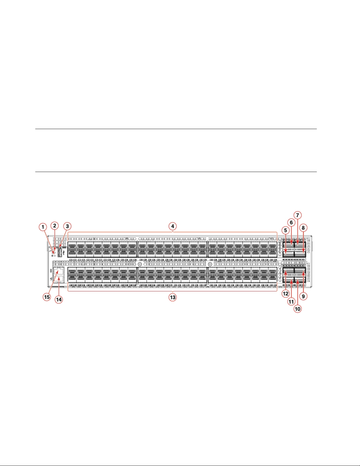
The following illustration shows the port-side view of the SAN128B-6 Fibre Channel switch.
Figure 1. Port-side view
1. System power LED
2. System status LED
3. USB port
4. 48 SFP+ 32-Gbps FC ports
5. QSFP port 1 ( FC ports 100 - 101 - 102 - 103 )
6. QSFP port 0 ( FC ports 96 - 97 - 98 - 99 )
7. QSFP port 2 ( FC ports 104 - 105 - 106 - 107 )
8. QSFP port 3 ( FC ports 108 - 109 - 110 - 111 )
9. QSFP port 6 ( FC ports 120 - 121 - 122 - 123 )
10. QSFP port 7 ( FC ports 124 - 125 - 126 - 127 )
11. QSFP port 5 ( FC ports 116 - 117 - 118 - 119 )
2 SAN128B-6 Installation, Service, and User Guide
Page 23
12. QSFP port 4 ( FC ports 112 - 113 - 114 - 115 )
13. 48 SFP+ 32-Gbps FC ports
14. 10/100/1000 Mbps RJ-45 Ethernet management port
15. UART RJ-45 serial console port
Table 2. SFP+ ports numbering
0 1 2 3 8 9 10 11 16 17 18 19 24 25 26 27 32 33 34 35 40 41 42 43
4 5 6 7 12 13 14 15 20 21 22 23 28 29 30 31 36 37 38 39 44 45 46 47
48 49 50 51 56 57 58 59 64 65 66 67 72 73 74 75 80 81 82 83 88 89 90 91
52 53 54 55 60 61 62 63 68 69 70 71 76 77 78 79 84 85 86 87 92 93 94 95
Table 3. QSFP ports numbering
QSFP port 0 ( FC ports 96 - 97 - 98 - 99 ) QSFP port 2 ( FC ports 104 - 105 - 106 - 107 )
QSFP port 1 ( FC ports 100 - 101 - 102 - 103 ) QSFP port 3 ( FC ports 108 - 109 - 110 - 111 )
QSFP port 4 ( FC ports 112 - 113 - 114 - 115 ) QSFP port 6 ( FC ports 120 - 121 - 122 - 123 )
QSFP port 5 ( FC ports 116 - 117 - 118 - 119 ) QSFP port 7 ( FC ports 124 - 125 - 126 - 127 )
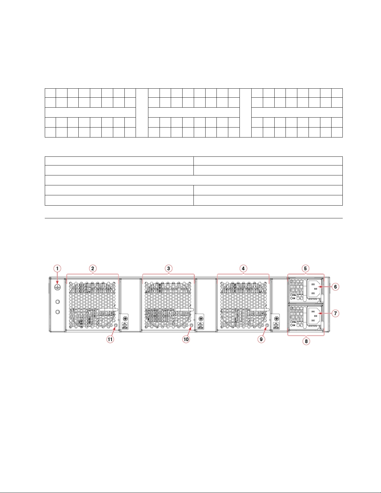
Nonport-side view
The following illustration shows the nonport-side view of the SAN128B-6 FC switch.
Figure 2. Nonport-side view with AC power supply and fan assembly units
1. Ground cable connector
2. Fan assembly unit 1
3. Fan assembly unit 2
4. Fan assembly unit 3
5. Power supply unit 1
6. Power supply receptacle 1
7. Power supply receptacle 2
8. Power supply unit 2
9. Fan assembly unit 3 status LED
10. Fan assembly unit 2 status LED
Device Overview 3
Page 24

11. Fan assembly unit 1 status LED
Device management options
You can use the management functions built into the device to monitor the fabric topology, port status,
physical status, and other information to help you analyze switch performance and to accelerate system
debugging. The device automatically performs a power-on self-test (POST) each time it is turned on. A
RASlog message is generated for any detected startup errors.
You can manage the device using any of the management options listed in the following table.
Table 4. Management options for the device
Management tool Out-of-band support Reference documents
Command line interface (CLI)
Up to two admin sessions and four
user sessions simultaneously.
EZSwitchSetup
EZSwitchSetup helps to complete
the basic configuration for
single-switch setup.
Web Tools Ethernet or serial
Standard SNMP applications Ethernet or serial
Management Server Ethernet or serial
IBM Network Advisor (NA)
NA must be purchased separately.
Ethernet or serial
connection
Ethernet or serial
connection
connection
connection
connection
Ethernet or serial
connection
Fabric OS Administration Guide
Fabric OS Command Reference
EZSwitchSetup Software Installation Guide
EZSwitchSetup Administrator's Guide
Web Tools Administration Guide
Fabric OS MIB Reference
Fabric OS Administration Guide
Fabric OS Command Reference
IBM Network Advisor documentation set
4 SAN128B-6 Installation, Service, and User Guide
Page 25
Preparing for the Installation
Use the following precautions and requirements for successful installation and operation of the switch.
Safety precautions
When using this product, observe all danger, caution, and attention notices in this manual. The safety
notices are accompanied by symbols that represent the severity of the safety condition
General precautions
DANGER
The procedures in this manual are for qualified service personnel.
DANGER
Before beginning the installation, see the precautions in “Power precautions.”
DANGER
Be careful not to accidently insert your fingers into the fan tray while removing it
from the chassis. The fan may still be spinning at a high speed.
CAUTION:
Changes or modifications made to this device that are not expressly approved by the
party responsible for compliance could void the user's authority to operate the equipment.
CAUTION:
Disassembling any part of the power supply and fan assembly voids the warranty and
regulatory certifications. There are no user-serviceable parts inside the power supply and
fan assembly.
CAUTION:
Make sure the airflow around the front, and back of the device is not restricted.
CAUTION:
Ensure that the airflow direction of the power supply unit matches that of the installed
fan tray. The power supplies and fan trays are clearly labeled with either a green arrow
with an "E", or an orange arrow with an "I."
© Copyright IBM Corp. 2018 5
Page 26
CAUTION:
Never leave tools inside the chassis.
CAUTION:
To protect the serial port from damage, keep the cover on the port when not in use.
CAUTION:
If you do not install a module or a power supply in a slot, you must keep the slot filler
panel in place. If you run the chassis with an uncovered slot, the system will overheat.
CAUTION:
Do not install the device in an environment where the operating ambient temperature
might exceed 40°C (104°F).
ESD precautions
Attention: Many of the field replaceable units (FRUs) are sensitive to electrostatic discharge (ESD), and
can potentially be damaged by improper handling. When working with any FRU, use correct ESD
precautions:
v Attach ground to the indicated area on the chassis
v Wear a wrist grounding strap connected to chassis ground (if the switch is plugged in) or a bench
ground.
Note: For safety reasons, the ESD wrist strap should contain a series 1 megaohm resistor.
v Store ESD-sensitive components in antistatic packaging
DANGER
For safety reasons, the ESD wrist strap should contain a series 1 megaohm resistor.
CAUTION:
Before plugging a cable into any port, be sure to discharge the voltage stored on the cable
by touching the electrical contacts to ground surface.
CAUTION:
Static electricity can damage the chassis and other electronic devices. To avoid damage,
keep static-sensitive devices in their static-protective packages until you are ready to
install them.
Note: Wear a wrist grounding strap connected to the chassis ground (if the device is plugged in) or to a
bench ground.
6 SAN128B-6 Installation, Service, and User Guide
Page 27
Power precautions
DANGER
Make sure that the power source circuits are properly grounded, then use the power
cord supplied with the device to connect it to the power source.
DANGER
If the installation requires a different power cord than the one supplied with the
device, make sure you use a power cord displaying the mark of the safety agency that
defines the regulations for power cords in your country. The mark is your assurance
that the power cord can be used safely with the device.
DANGER
This device might have more than one power cord. To reduce the risk of electric shock,
disconnect all power cords before servicing.
DANGER
Remove both power cords before servicing.
DANGER
Disconnect the power cord from all power sources to completely remove power from
the device.
DANGER
To avoid high voltage shock, do not open the device while the power is on.
DANGER
Batteries used for RTC/NVRAM backup are not located in operator-access areas. There
is a risk of explosion if a battery is replace by an incorrect type. Dispose of used
components with batteries according to local ordinance and regulations.
Preparing for the Installation 7
Page 28
CAUTION:
18-32kg(39.7-70.5lbs)
svc00167
18-32kg(39.7-70.5lbs)
svc00167
18-32kg(39.7-70.5lbs)
svc00167
18-32kg(39.7-70.5lbs)
svc00167
Use a separate branch circuit for each power cord, which provides redundancy in case one
of the circuits fails.
CAUTION:
Ensure that the device does not overload the power circuits, wiring, and over-current
protection. To determine the possibility of overloading the supply circuits, add the
ampere (amp) ratings of all devices installed on the same circuit as the device. Compare
this total with the rating limit for the circuit. The maximum ampere ratings are usually
printed on the devices near the input power connectors.
CAUTION:
The power supply switch must be in the off position when you insert the power supply
into the chassis. Damage to the switch can result if a live power supply is installed.
CAUTION:
Carefully follow the mechanical guides on each side of the power supply slot and make
sure the power supply is properly inserted in the guides. Never insert the power supply
upside down.
Note: Device control processors and management modules may contain batteries for RTC or NVRAM
backup. Dispose of components containing batteries as required by local ordinances and regulations.
Lifting and weight-related precautions
DANGER
Use safe lifting practices when moving the product.
DANGER
Mount the devices you install in a rack as low as possible. Place the heaviest device at
the bottom and progressively place lighter devices above.
DANGER
Make sure the rack housing the device is adequately secured to prevent it from
becoming unstable or falling over.
CAUTION:
Do not use the port cover tabs to lift the module. They are not designed to support the
weight of the module, which can fall and be damaged.
8 SAN128B-6 Installation, Service, and User Guide
Page 29
18-32kg(39.7-70.5lbs)
svc00167
CAUTION:
To prevent damage to the chassis and components, never attempt to lift the chassis using
the fan or power supply handles. These handles were not designed to support the weight
of the chassis.
Laser precautions
DANGER
All fiber-optic interfaces use Class 1 lasers.
DANGER
Use only optical transceivers that are qualified by IBM and comply with the FDA
Class 1 radiation performance requirements defined in 21 CFR Subchapter I, and with
IEC 60825 and EN60825. Optical products that do not comply with these standards
might emit light that is hazardous to the eyes.
Facility requirements
Before installing the device, be sure the following facilities requirements are met.
Table 5. Facility requirements
Type Requirements
Electrical
Thermal
Rack (when
rack-mounted)
v Adequate supply circuit, line fusing, and wire size, as specified by the electrical rating on
the switch nameplate
v Circuit protected by a circuit breaker and grounded in accordance with local electrical
codes
Refer to the Technical Specifications at the end of this guide for complete power supply
specifications.
v A minimum airflow of 79.8 cubic meters/hour (47 cubic ft/min.) available in the
immediate vicinity of the switch
Note: Although this airflow may exceed the airflow maximum listed in the device
Technical Specifications, the additional airflow is recommended to pressurize the inlet
(cool isle) side of rack installations relative to the exhaust side to minimize recirculation
of hot air back to the inlet side.
v Ambient air temperature not exceeding 40°C (104°F) while the switch is operating
v Two rack unit (2U) in a 48.3 cm (19-inch) rack
v All equipment in the rack grounded through a reliable branch circuit connection
v Additional weight of switch not to exceed the rack’s weight limits
v Rack secured to ensure stability in case of unexpected movement
Preparing for the Installation 9
Page 30

Quick installation checklist
This checklist provides a high-level overview of the basic installation process from the planning stage to
the point where the device comes online and is ready to be deployed. Completing all the tasks in the
suggested order ensures successful installation. Brocade recommends that you print this checklist and
take it to the installation site.
Pre-installation tasks
Review all installation requirements ahead of time as part of your site preparation. Careful planning and
site preparation ensures seamless installation, especially when installing multiple devices.
Table 6. Installation prerequisites
Task Task details or additional information Completed
Unpack the device. Take an inventory of the hardware components included in your
shipment. Refer to “Shipping carton contents” on page 12.
Gather necessary components and
required tools.
Review the safety precautions. Refer to “Safety precautions” on page 5. For translations, refer to
Plan the installation. Decide whether you want to install the unit on a flat surface or in a
Review and verify installation
requirements.
Gather network configuration
parameters.
Review the time and items required information at the beginning of
each chapter to ensure you have gathered all necessary components
required for the following installation tasks:
v “Mounting the switch” on page 13
v “Power Supply Assemblies” on page 57
v “Fan Assemblies” on page 65
v “Installing Transceivers and Cables” on page 45
“Cautions” on page xi at the end of this guide.
rack. For rack installation, obtain the appropriate rack mount kit.
Refer to “Mounting the switch” on page 13.
Verify that the following requirements are met. Refer to “Facility
requirements” on page 9.
v Power requirements
v Environmental requirements
v Clearance for standalone or rack installation
v IP address:
v Subnet mask:
v Default gateway:
v Domain ID:
v Time zone:
Installation and initial configuration
The initial setup includes mounting the device on a flat surface or in a rack and completing the
configuration tasks necessary to bring the device online and verify the operation.
10 SAN128B-6 Installation, Service, and User Guide
Page 31

Table 7. Installation and basic system configuration
Task Task details or additional information Completed
Mount the device. Choose one of the following mounting options:
v Mount the device as a standalone unit. Refer to“Standalone
installation” on page 14.
v Mount the device in a four-post rack. Refer to“Installing the
Universal Four-Post Rack Kit” on page 14.
v Mount the device in a two-post rack. Refer to“Installing the
Universal Two-Post Rack Kit” on page 26.
Check the airflow of the power
supply and fan assembly
The airflow direction of the power supply and fan should match.
The power supplies and fan trays are clearly labeled with either a
green arrow with an "E", or an orange arrow with an "I." For more
details, refer to “Identifying the airflow direction” on page 58.
Gather all components required
Refer to “Items required” on page 37.
for the initial setup.
Provide power to the device. Refer to “Providing power to the device” on page 37.
Attach a management station,
establish a serial connection, and
change the default passwords
Refer to “Establishing a first-time serial connection” on page 37.
After completing this task, log in to the serial port to configure the
device.
(optional).
Set the IP address, subnet mask,
and the default gateway IP
address.
Use the ipaddrset command to configure a static device IP address,
subnet mask, and gateway IP address, or you can use a DHCP
server to obtain the information dynamically. Refer to “Configuring
the IP address” on page 38.
Set the date and time.
v Use the date command to display and set the date and time.
v Use the tstimezone command to display and set the time zone.
v Use the tsclockserver command to synchronize the time with an
external NTP server.
Refer to “Setting the date and time” on page 39 for more
information.
Customize the switch name and
chassis name.
v Use the swicthname command to change the default switch name.
v Use the chassisname command to change the default chassis
name.
Refer to “Customizing the chassis name and switch name” on page
41 for more information.
Establish an Ethernet connection. By establishing an Ethernet connection, you can complete the
device configuration using a serial session, Telnet, or management
application, such as Brocade Network Advisor. Refer to
“Establishing an Ethernet connection” on page 41.
Optional: Configure the DNS
service.
Optional: Customize the domain
ID.
Use the dnsconfig command to create DNS server entries. Refer to
the Brocade Fabric OS Administration Guide.
Use the configure command to change the domain ID (default ID
is 1). Refer to “Setting the domain ID” on page 41 for more
information.
Preparing for the Installation 11
Page 32

Table 7. Installation and basic system configuration (continued)
Task Task details or additional information Completed
Verify that the device operates
correctly.
Back up the configuration. Use the interactive configupload command to back up the
Optional: Power off the devices. Enter the shutdown command and wait for the device to power
v Check the LEDs to verify operation of functional parts. Refer
to“Port-side LED locations” on page 51 and“Nonport-side LED
locations” on page 54.
v The following commands can be useful to establish an
operational baseline for the device. Refer to theFabric OS
Command Reference for more information on these commands.
– psshow
– fanshow
– tempshow
– historyshow
– errdump
configuration. Refer to “Verifying correct operation” on page 42 for
more information.
down, and then unplug the power cords. Refer to “Powering down
the device” on page 43 for more information.
Shipping carton contents
When unpacking the switch, verify that the contents of the shipping carton is complete. Save the
shipping carton and packaging in the event you need to return the shipment.
v The SAN128B-6 switch
v An accessory kit containing the following items:
– A serial cable
– Two 6-ft. power cords
– Power cord retainer clips
– Rubber feet
– China-RoHS Hazardous/Toxic Substance statement
– Network Advisor web pointer card.
– EZSwitch web pointer card
– Documentation web pointer card
v Inner foam
12 SAN128B-6 Installation, Service, and User Guide
Page 33

Mounting the switch
18-32kg(39.7-70.5lbs)
svc00167
18-32kg(39.7-70.5lbs)
svc00167
18-32kg(39.7-70.5lbs)
svc00167
18-32kg(39.7-70.5lbs)
svc00167
You can install the SAN128B-6 switch in several ways:
v As a standalone unit on a flat surface, for example, a table top. Use the rubber feet included with the
shipment to secure the device on the surface. No other equipment is required for desktop installation.
v In a four-post EIA rack: You will need a Universal Four-Post Rack Kit to install devices in EIA racks
that are between L-13.7 to 81.28 cm deep (L-5.0 to 32.0 in.), where L is the chassis depth.
v In a two-post Telco rack: You will need a Universal Two-Post Rack Kit to install 2U devices in a
two-post telecommunications (Telco) rack.
Note: Review the “Precautions specific to mounting” before mounting the switch.
Precautions specific to mounting
The following precautions specifically apply to mounting the device.
DANGER
Use safe lifting practices when moving the product.
DANGER
Mount the devices you install in a rack as low as possible. Place the heaviest device at
the bottom and progressively place lighter devices above.
CAUTION:
Make sure the airflow around the front, and back of the device is not restricted.
CAUTION:
Never leave tools inside the chassis.
CAUTION:
Do not use the port cover tabs to lift the module. They are not designed to support the
weight of the module, which can fall and be damaged.
CAUTION:
To prevent damage to the chassis and components, never attempt to lift the chassis using
the fan or power supply handles. These handles were not designed to support the weight
of the chassis.
© Copyright IBM Corp. 2018 13
Page 34

Standalone installation
About this task
Complete the following steps to install the device as a standalone unit on a table.
Procedure
1. Unpack the device and verify the items listed under “Shipping carton contents” on page 12 are
present and undamaged.
2. Apply the adhesive rubber feet to the underside of the device. The rubber feet help prevent the device
from sliding off the supporting surface.
a. Clean the indentations at each corner of the bottom of the device to ensure that they are free of
dust or other debris that might lessen the adhesion of the feet.
b. With the adhesive side against the chassis, place one rubber foot in each indentation and press
into place.
3. Place the device on a sturdy flat surface.
4. Provide power to the device as described in “Providing power to the device” on page 37.
Note: Do not connect the device to the network until the IP address is set correctly. For instructions
on how to set the IP address, refer to “Configuring the IP address” on page 38.
Installing the Universal Four-Post Rack Kit
Use the following instructions to install 1U and 2U devices in EIA racks that are between L-12.7 to 81.28
cm deep (L-5.0 to 32.0 in.), where L is the chassis depth, using the Universal Four-Post Rack Kit.
There are two ways you can mount the device in a four-post rack:
v With the port side flush with the front posts.
v With the nonport side flush with the rear posts in a recessed position. A recessed position allows a
more gradual bend in the fiber-optic cables connected to the switch and less interference in the aisle at
the front of the rack.
Table 8. Space requirements
Chassis with
port-side side
vents Notes Chassis depth
No Applicable to port-side and
nonport-side flush mounts.
Yes Applicable to port-side flush
mounts.
Yes Applicable to nonport-side flush
mounts.
L L-12.7 cm (L-5 in.) 81.28 cm (32 in.)
L L-12.7 cm (L-5 in.) 81.28 cm (32 in.)
L L 81.28 cm (32 in.)
Minimum rack
depth
Maximum rack
depth
Note that if chassis depth (L) is less than 40.64 cm (16 in.), the chassis will not fit into a rack with a
maximum depth of 81.28 cm (32 in.) using the universal four-post rack kit. The maximum rack depth for
a chassis less than 40.64 cm (16 in.) is 81.28 cm (32 in.) minus the difference between the chassis depth
and 40.64 cm (16 in.). For example, a chassis with a depth (L) of 35.56 cm (14 in.) is 5.08 cm (2 in.)
smaller than 40.64 cm (16 in.), so it will install into a rack with a maximum depth of 81.28 cm (32 in.) -
5.08 cm (2 in.) = 76.2 cm (30 in.).
Observe the following when mounting this device:
14 SAN128B-6 Installation, Service, and User Guide
Page 35

v Two people are required to install the device in a rack. One person holds the device, while the other
screws in the front and rear brackets.
v Before mounting your device, review any specific installation and facility requirements in this
Hardware Installation Guide.
v Hardware devices illustrated in these procedures are only for reference and may not depict the device
you are installing into the rack.
Time and items required
Allow 15 to 30 minutes to complete the installation.
The following items are required to install the device using the Universal Four-Post Rack Kit:
v #2 Phillips torque screwdriver
v 1/4-inch slotted-blade torque screwdriver
Parts list
The following parts are provided wit the 1U, 1.5U, and 2U Universal Kit for Four Post Racks Installation.
Mounting the switch 15
Page 36

Figure 3. Rack kit parts
1. Front brackets (2)
2. Extension brackets, medium (2)
3. Rear brackets, short (2)
4. Rear brackets, long (2)
5. Extension brackets, long (2)
6. Screw, 8-32 x 5/16-in., panhead Phillips (8)
7. Screw, 8-32 x 5/16-in., flathead Phillips (16)
8. Screw, 6-32 x 1/4-in., panhead Phillips (8)
9. Screw, 10-32 x 5/8-in., panhead Phillips (8)
10. Retainer nut, 10-32 (8)
Ensure that the items listed and illustrated are included in the kit. Note that not all parts may be used
with certain installations depending on the device type.
CAUTION:
CAUTION: Use the screws specified in the procedure. Using longer screws can damage the device.
16 SAN128B-6 Installation, Service, and User Guide
Page 37

Flush-front mounting
CAUTION:
The device must be turned off and disconnected from the fabric during this procedure.
Note: The illustrations in the rack installation procedures are for reference only and may not show the
device that you are installing.
Complete the following tasks to install the device in a four-post rack.
1. Attaching the front brackets
2. Attaching the bracket extensions to the device
3. Installing the device in the rack
4. Attaching the rear brackets to the extensions
5. Attaching the rear brackets to the rack posts
Attaching the front brackets
About this task
Complete the following steps to attach the front brackets to the device.
Procedure
1. Position the right front bracket with the flat side against the right side of the device at the front of the
device, as shown in Figure 4.
2. Insert four 8-32 x 5/16-in. flathead screws through the vertically aligned holes in the bracket and then
into the holes on the side of the device. Use the upper and lower screw holes, leaving the center holes
empty.
3. Repeat step 1 and step 2 to attach the left front bracket to the left side of the device.
4. Tighten all the 8-32 x 5/16-in. screws to a torque of 15 in-lb (17 cm-kg).
Figure 4. Attaching the front brackets
1. The SAN128B-6 device
2. Front brackets
Mounting the switch 17
Page 38

3. Screws, 8-32 x 5/16-in., flathead Phillips
Attaching the bracket extensions to the device
About this task
Complete the following steps to attach the extension brackets to the device. There are medium and long
extension brackets that you can use for this step.
Procedure
1. Select the proper length bracket extension for your rack depth.
2. Position the right bracket extension along the side of the device as shown in Figure 5.
3. Insert four 8-32 x 5/16-in. flathead screws through the vertically aligned holes in the bracket extension
and then into the holes on the side of the device. Use the upper and lower screw holes, leaving the
center holes empty.
4. Repeat step 2 and step 3 to attach the left bracket extension to the left side of the device.
5. Tighten all the 8-32 x 5/16-in. screws to a torque of 15 in-lb (17 cm-kg).
Figure 5. Attaching the bracket extensions to the device
Bracket extension
Screws, 8-32 x 5/16-in., flathead Phillips
Installing the device in the rack
About this task
Complete the following steps to install the device in the rack.
Procedure
1. Position the device in the rack, as shown in Figure 6 on page 19, providing temporary support under
the device until the rail kit is secured to the rack.
2. Attach the right front bracket to the right front rack post using two 10-32 x 5/8-in. panhead screws
and two retainer nuts. Use the upper and lower holes in the bracket.
18 SAN128B-6 Installation, Service, and User Guide
Page 39

3. Attach the left front bracket to the left front rack post using two 10-32 x 5/8-in. panhead screws and
two retainer nuts. Use the upper and lower holes in the bracket.
4. Tighten all the 10-32 x 5/8-in. screws to a torque of 25 in-lb (29 cm-kg).
Figure 6. Positioning the device in the rack
1. Screws, 10-32 x 5/8-in., panhead Phillips
2. Retainer nuts, 10-32
Attaching the rear brackets to the extensions
About this task
Complete the following steps to attach the rear brackets to the extensions. There are short and long rear
brackets that you can use for this step. Choose the correct bracket for the depth of your rack.
Procedure
1. Select the proper length rear bracket for your rack depth.
2. Slide the right rear bracket onto the right bracket extension, as shown in the following figure.
3. Attach the brackets using four 6-32 x 1/4-in. panhead screws. If possible, leave at least one empty
vertical pair of holes between the screws for better support.
4. Repeat step 2 and 3 to attach the left rear bracket to the left bracket extension.
5. Adjust the brackets to the rack depth and tighten all the 6-32 x 1/4-in. screws to a torque of 9 in-lb
(10 cm-kg).
Mounting the switch 19
Page 40

Figure 7. Attaching the rear brackets to the extensions
1. Rear brackets
2. Screws, 6-32 x 1/4-in., panhead Phillips
Attaching the rear brackets to the rack posts
About this task
Complete the following steps to attach the rear brackets to the rack posts.
Procedure
1. Attach the right rear bracket to the right rear rack post using two 10-32 x 5/8-in. panhead screws and
two retainer nuts, as shown in Figure 8 on page 21. Use the upper and lower holes in the bracket.
2. Attach the left rear bracket to the left rear rack post using two 10-32 x 5/8-in. panhead screws and
two retainer nuts. Use the upper and lower holes in the bracket.
3. Tighten all the 10-32 x 5/8-in. screws to a torque of 25 in-lb (29 cm-kg).
20 SAN128B-6 Installation, Service, and User Guide
Page 41

Figure 8. Attaching the rear brackets to the rack posts
1. Screws, 10-32 x 5/8-in., panhead Phillips
2. Retainer nuts, 10-32
Flush-rear (recessed) mounting
The flush-rear (recessed) mounting is similar to the flush-front mounting except that the brackets are
reversed on the device.
CAUTION:
The device must be turned off and disconnected from the fabric during this procedure.
Note: The illustrations in the rack installation procedures show a 1U device, but the instructions are the
same for a 2U device. The illustrations in the rack installation procedures are for reference only and may
not show the actual device.
Complete the following tasks to install the device in a four-post rack:
1. Attaching the front brackets to the rear of the device
2. Attaching the extensions to the front of the device
3. Installing the device in the rack
4. Attaching the rear brackets to the extensions at the front of the device
5. Attaching the rear brackets to the front rack posts
Attaching the front brackets to the rear of the device
About this task
Note: In this installation, the brackets are named as listed in the parts list even though the installation of
the brackets is reversed from the flush-front installation.
Complete the following steps to attach the front brackets to the rear of the device.
Mounting the switch 21
Page 42

Procedure
1. Position the right front bracket with the flat side against the right rear side of the device, as shown in
Figure 9.
2. Insert four 8-32 x 5/16-in. flathead screws through the vertically aligned holes in the bracket and then
into the holes on the side of the device. Use the upper and lower screw holes, leaving the center holes
empty.
3. Repeat step 1 and step 2 to attach the left front bracket to the left side of the device.
4. Tighten all the 8-32 x 5/16-in. screws to a torque of 15 in-lb (17 cm-kg).
Figure 9. Attaching the front brackets to the rear of the device
1. The SAN128B-6 device
2. Front brackets
3. Screws, 8-32 x 5/16-in., flathead Phillips
Attaching the bracket extensions to the front of the device
About this task
Complete the following steps to attach the bracket extensions to the front of the device. There are
medium and long extension brackets that you can use for this step.
Procedure
1. Select the proper length extension bracket for your rack depth.
2. Position the right bracket extension along the side of the device as shown in Figure 10 on page 23.
3. Insert four 8-32 x 5/16-in. flathead screws through the vertically aligned holes in the bracket extension
and then into the holes on the side of the device. Use the upper and lower screw holes, leaving the
center holes empty.
4. Repeat step 2 and step 3 to attach the left front bracket extension to the left side of the device.
5. Tighten all the 8-32 x 5/16-in. screws to a torque of 15 in-lb (17 cm-kg).
22 SAN128B-6 Installation, Service, and User Guide
Page 43

Figure 10. Attaching the bracket extensions to the device
1. Extension brackets
2. Screws, 8-32 x 5/16-in., flathead Phillips
Installing the device in the rack
About this task
Complete the following steps to install the device in the rack.
Procedure
1. Position the device in the rack, as shown in Figure 11 on page 24, providing temporary support under
the device until the rail kit is secured to the rack.
2. Attach the right front bracket to the right rear rack post using two 10-32 x 5/8-in. panhead screws
and two retainer nuts. Use the upper and lower holes in the bracket.
3. Attach the left front bracket to the left rear rack post using two 10-32 x 5/8-in. panhead screws and
two retainer nuts. Use the upper and lower holes in the bracket.
4. Tighten all the 10-32 x 5/8-in. screws to a torque of 25 in-lb (29 cm-kg).
Mounting the switch 23
Page 44

Figure 11. Positioning the device in the rack
Screws, 10-32 x 5/8-in., panhead Phillips
Retainer nuts, 10-32
Attaching the rear brackets to the extensions at the front of the device
About this task
Complete the following steps to attach the rear brackets to the extensions. There are short and long front
brackets that you can use for this step.
Procedure
1. Select the proper length rear bracket for your rack depth.
2. Slide the right rear bracket onto the right extension.
The short rear brackets are shown in Figure 12 on page 25. Use the first and third vertical pairs of
holes for the screws.
Refer to Figure 13 on page 25 for the positioning of the short or long brackets and screws.
3. Attach the brackets using four 6-32 x 1/4-in. panhead screws.
4. Repeat step 2 and step 3 to attach the left rear bracket to the left extension.
5. Adjust the brackets to the rack depth and tighten all the 6-32 x 1/4-in. screws to a torque of 9 in-lb
(10 cm-kg).
24 SAN128B-6 Installation, Service, and User Guide
Page 45

Figure 12. Attaching the rear brackets to the extensions at the front of the device
1. Rear brackets, short
2. Screws, 6-32 x 1/4-in., panhead Phillips
Figure 13. Attaching the short or long rear brackets to the extensions
1. Rear bracket, short or long
2. Screws, 6-32 x 1/4-in., panhead Phillips
Mounting the switch 25
Page 46

Attaching the rear brackets to the front rack posts
About this task
Complete the following steps to attach the rear brackets to the front rack posts.
Procedure
1. Attach the right rear bracket to the right front rack post using two 10-32 x 5/8-in. screws and two
retainer nuts, as shown in Figure 14. Use the upper and lower holes in the bracket.
2. Attach the left rear bracket to the left front rack post using two 10-32 x 5/8-in. screws and two
retainer nuts. Use the upper and lower holes in the bracket.
3. Tighten all the 10-32 x 5/8-in. screws to a torque of 25 in-lb (29 cm-kg).
Figure 14. Attaching the rear brackets to the front rack posts
1. Screws, 10-32 x 5/8-in., panhead Phillips
2. Retainer nuts, 10-32
Installing the Universal Two-Post Rack Kit
Use the following instructions to install a Brocade 1U or 2U device in a two-post telecommunications
(Telco) rack using the Universal Two-Post Rack Kit.
There are two ways you can mount the device in a two-post rack:
v With the port side flush with the front posts
v With the posts mounted to the mid-section of the device
Observe the following when mounting this device:
v Two people are required to install the device in a rack. One person should hold the device, while the
other while the other screws in the front and rear brackets.
v Before mounting your device, review any specific installation and facility requirements in this
Hardware Installation Guide.
26 SAN128B-6 Installation, Service, and User Guide
Page 47

v Hardware devices illustrated in these procedures are only for reference and may not depict the device
you are installing into the rack.
Time and items required
Allow 15 to 30 minutes to complete the installation.
The following items are required to install the device using the Universal Two-Post Rack Kit:
v #2 Phillips torque screwdriver
v 1/4-inch slotted-blade torque screwdriver
Parts list
The following parts are provided with the Universal Two-Post Rack Kit Installation.
Figure 15. Rack kit parts
1. Front brackets (2)
2. Rear brackets, 3-5 inch post (2)
3. Rear brackets, 5-6 inch post (2)
4. Screw, 8-32 x 5/16-in., panhead Phillips (8)
5. Screw, 8-32 x 5/16-in., flathead Phillips (16)
6. Screw, 6-32 x 1/4-in., panhead Phillips (8)
7. Screw, 10-32 x 5/8-in., panhead Phillips (8)
8. Retainer nut, 10-32 (8)
Ensure that the items listed and illustrated above are included in the kit. Note that not all parts may be
used with certain installations depending on the device type.
Mounting the switch 27
Page 48

Flush-front mounting
Observe the following notes when using this procedure:
v The device must be turned off and disconnected from the fabric during this procedure.
v The illustrations in this document show a 1U device, but the instructions are the same for a 2U device.
v The illustrations for this procedure show a two-post rack with narrow posts (3- to 5-inch) as an
example.
v The illustrations in the rack installation procedures are for reference only and may not show the actual
device.
CAUTION:
Use the screws specified in the procedure. Using longer screws can damage the device.
Complete the following tasks to install the device in a rack:
1. “Attaching the front brackets to the device”
2. “Attaching the front brackets to the rack” on page 29
3. “Attaching the rear brackets to the rack” on page 30
4. “Attaching the rear brackets to the device” on page 31
Attaching the front brackets to the device
About this task
Complete the following steps to attach the front brackets to the device.
Procedure
1. Position the right front bracket with the flat side against the right side of the device, as shown in
Figure 16 on page 29.
2. Insert four 8-32 x 5/16-in. flathead screws through the vertically aligned holes in the bracket and then
into the holes on the side of the device. Use the upper and lower screw holes, leaving the center holes
empty.
3. Repeat step 1 and step 2 to attach the left front bracket to the left side of the device.
4. Tighten all the 8-32 x 5/16-in. screws to a torque of 15 in-lb (17 cm-kg).
28 SAN128B-6 Installation, Service, and User Guide
Page 49

Figure 16. Attaching the front brackets
1. The SAN128B-6 device
2. Front brackets, right and left
3. Screws, 8-32 x 5/16-in., flathead Phillips
Attaching the front brackets to the rack
About this task
Complete the following steps to install the device in the rack.
Procedure
1. Position the device in the rack, as shown in (Figure 17 on page 30), providing temporary support
under the device until the rack kit is fully secured to the rack.
2. Attach the right front bracket to the right rack upright using two 10-32 x 5/8-in. panhead screws and
two retainer nuts. Use the upper and lower holes in the bracket.
3. Attach the left front bracket to the left rack upright using two 10-32 x 5/8-in. panhead screws and
two retainer nuts. Use the upper and lower holes in the bracket.
4. Tighten all the 10-32 x 5/8-in. screws to a torque of 25 in-lb. (29 cm-kg).
Mounting the switch 29
Page 50

Figure 17. Attaching front brackets to a rack
1. Screws, 10-32 x 5/8-in., panhead Phillips
2. Retainer nuts, 10-32
Attaching the rear brackets to the rack
About this task
Complete the following steps to attach the rear brackets to the rack.
Procedure
1. Select the proper length bracket for your post width. If your posts are three to five inches wide, use
the brackets marked 3-5 INCH. If your posts are five to six inches wide, use the brackets marked 5-6
INCH.
2. Position the right rear bracket in the right rear of the device, as shown in Attaching rear brackets to
the rack.
3. Attach the bracket to the right rack upright using two 10-32 x 5/8-in. panhead screws and two
retainer nuts. Use the upper and lower holes in the bracket.
4. Repeat step 2 and step 3 to attach the left rear bracket to the left rack upright.
5. Tighten all the 10-32 x 5/8-in. screws to a torque of 25 in-lb. (29 cm-kg).
30 SAN128B-6 Installation, Service, and User Guide
Page 51

Figure 18. Attaching the rear brackets to a rack
1. Retainer nuts, 10-32
2. Rear brackets
3. Screws, 10-32 x 5/8-in., panhead Phillips
Attaching the rear brackets to the device
About this task
Complete the following steps to attach the rear brackets to the device.
Procedure
1. Align the right rear bracket to the right rear of the device and use four 8-32 x 5/16-in. panhead
screws to attach the bracket to the device, as shown in Figure 19 on page 32. Be sure to insert the
screws through the upper and lower slots in the bracket.
2. Align the left rear bracket to the left rear of the device and use four 8-32 x 5/16-in. panhead screws to
attach the bracket to the device. Again, use the upper and lower slots in the bracket.
3. Tighten all the 8-32 x 5/16-in. screws to a torque of 15 in-lb (17 cm-kg).
Mounting the switch 31
Page 52

Figure 19. Attaching the rear brackets to the device
1. Screws, 8-32 x 5/16-in., panhead Phillips
Mid-mounting
Observe the following notes when using this procedure:
v The device must be turned off and disconnected from the fabric during this procedure.
v The illustrations in this document show a 1U device, but the instructions are the same for a 2U device.
v The illustrations in the rack installation procedures are for reference only and may not show the actual
device.
Complete the following tasks to install the device in a rack:
1. “Attaching the front brackets to the device”
2. “Attaching the front brackets to the rack” on page 33
3. “Attaching the rear brackets to the rack” on page 34
4. “Attaching the rear brackets to the device” on page 35
Attaching the front brackets to the device
About this task
Complete the following steps to attach the front brackets to the device.
Procedure
1. Position the right front bracket with the flat side against the right side of the device, as shown in
Figure 20 on page 33.
2. Insert four 8-32 x 5/16-in. flathead screws through the vertically aligned holes in the bracket and then
into the holes on the side of the device. Use the upper and lower screw holes, leaving the center holes
empty.
3. Repeat step 1 and step 2 to attach the left front bracket to the left side of the device.
4. Tighten all the 8-32 x 5/16-in. screws to a torque of 15 in-lb (17 cm-kg).
32 SAN128B-6 Installation, Service, and User Guide
Page 53

Figure 20. Attaching the front brackets
1. The SAN128B-6 device
2. Front brackets, right and left
3. Screws, 8-32 x 5/16-in., flathead Phillips
Attaching the front brackets to the rack
About this task
Complete the following steps to install the device in the rack.
Procedure
1. Position the device in the rack, as shown in Figure 21 on page 34, providing temporary support under
the device until the rack kit is fully secured to the rack.
2. Attach the right front bracket to the right rack upright using two 10-32 x 5/8-in. screws and two
retainer nuts. Use the upper and lower holes in the bracket.
3. Attach the left front bracket to the left rack upright using two 10-32 x 5/8-in. screws and two retainer
nuts. Use the upper and lower holes in the bracket.
4. Tighten all the 10-32 x 5/8-in. screws to a torque of 25 in-lb (29 cm-kg).
Mounting the switch 33
Page 54

Figure 21. Attaching front brackets to a rack
1. Screws, 10-32 x 5/8-in., panhead Phillips
2. Retainer nuts, 10-32
Attaching the rear brackets to the rack
About this task
Complete the following steps to attach the rear brackets to the rack.
Procedure
1. Select the proper length bracket for your post width. If your posts are three to five inches wide, use
the brackets marked 3-5 INCH. If your posts are five to six inches wide, use the brackets marked 5-6
INCH.
2. Position the right rear bracket in the right rear of the device, as shown in the following figure.
Whether you are using the 3-5 inch or the 5-6 inch bracket, the rear end of the bracket will be flush
with the back of the device.
3. Attach the brackets to the right rack upright using two 10-32 x 5/8-in. panhead screws and two
retainer nuts.
4. Repeat step 2 and step 3 to attach the left rear bracket to the left rack upright.
5. Tighten all the 10-32 x 5/8-in. screws to a torque of 25 in-lb (29 cm-kg).
34 SAN128B-6 Installation, Service, and User Guide
Page 55

Figure 22. Attaching the rear brackets to a rack
1. Retainer nuts, 10-32
2. Rear brackets (right and left)
3. Screws, 10-32 x 5/8-in., panhead Phillips
Attaching the rear brackets to the device
About this task
Complete the following steps to attach the rear brackets to the device.
Procedure
1. Align the right rear bracket to the right rear of the device and use four 8-32 x 5/16-in. panhead
screws to attach the bracket to the device, as shown in Figure 23 on page 36. Be sure to insert the
screws through the upper and lower slots in the bracket.
2. Align the left rear bracket to the left rear of the device and use four 8-32 x 5/16-in. panhead screws to
attach the bracket to the device. Again, use the upper and lower slots in the bracket.
3. Tighten all the 8-32 x 5/16-in. screws to a torque of 15 in-lb (17 cm-kg).
Mounting the switch 35
Page 56

Figure 23. Attaching the rear brackets to the device
1. Screws, 8-32 x 5/16-in., panhead Phillips
36 SAN128B-6 Installation, Service, and User Guide
Page 57

Initial Setup and Verification
Once you have set up the SAN128B-6 in a rack or as a standalone switch, it is time to attach power and
set up a basic configuration. If you are going to use the SAN128B-6 in a single-switch setup, you can use
EZSwitchSetup to complete the basic configuration.
See the EZSwitchSetup CD, included with the switch, for more information. You can also use the
SAN128B-6 Quick Start Guide. If you do not want to use EZSwitchSetup, follow the instructions in this
section.
Items required
The following items are required for initial setup and verification of the device:
v The device, mounted and installed with the required power supply and fan assemblies, transceivers,
and cables; and connected to a power source.
v A workstation computer with a terminal emulator application installed, such as PuTTY, XShell or
SecureCRT on Windows.
v An unused IP address with corresponding subnet mask and gateway address.
v A serial cable with an RJ-45 connector.
v An Ethernet cable.
v Access to an FTP server or USB device for backing up (uploading) or downloading the device
configuration (optional).
Providing power to the device
About this task
Perform the following steps to provide power to the device.
Procedure
1. Connect the power cords to both power supplies, and then to power sources on separate circuits to
protect against power failure. Ensure that the power cords have a minimum service loop of 6 inches
available and are routed to avoid stress.
2. Power on the power supplies by flipping both switches to the on position (the "I" symbol). The power
supply LEDs display amber until power-on self-test (POST) is complete, and then change to green.
The switch usually requires several minutes to boot and complete POST.
Note: Power is supplied to the device as soon as the first power supply is connected and turned on.
3. After POST is complete, verify that the switch power and switch status LEDs are green. For more
information about how to interpret POST, BOOT, and diagnostics tests, refer to “Monitoring the
device” on page 51.
Establishing a first-time serial connection
About this task
Perform the following steps to log in to the device through the serial connection.
© Copyright IBM Corp. 2018 37
Page 58

Procedure
1. Connect the serial cable to the serial port on the device and to an RS-232 serial port on the
workstation.
If the serial port on the workstation is RJ-45 instead of RS-232, remove the adapter on the end of the
serial cable and insert the exposed RJ-45 connector into the RJ-45 serial port on the workstation.
2. Disable any serial communication programs running on the workstation such as synchronization
programs.
3. Open a terminal emulator application such as PuTTY, XShell, or SecureCRT on a Windows PC, or
TERM, TIP, or C-Kermit in a LINUX environment, and configure the application as follows:
v In a Windows environment, use the following values:
Parameter Value
Bits per second 9600
Databits 8
Parity None
Stop bits 1
Flow control None (must be disabled on the host side)
Note: Flow control is not supported on the serial connection when attached to a remote terminal
and must be disabled on the customer-side remote terminal server in addition to the host-side
clients.
v In a UNIX environment using TIP, enter the following string at the prompt:
tip /dev/ttyb -9600.
If ttyb is already in use, use ttya instead and enter the following string at the prompt:
tip /dev/ttya -9600
4. When the terminal emulator application stops reporting information, press Enter to display the login
prompt.
Switch Console Login:
5. Log in to the device as admin, using the default password: password. You are prompted to change
the default admin and user passwords at initial login. Make sure to write down the new passwords
and keep this information in a secure location.
Fabric OS (swDir)
swDir login: admin
Password:
Please change your passwords now.
Use Control-C to exit or press ’Enter’ key to proceed.
swDir:admin>
6. Modify passwords. To skip modifying the password, press Ctrl+C.
Note: Initial passwords can be 8 to 40 characters long. They must begin with an alphabetic character.
They can include numeric characters, the period (.), and the underscore (_) only. Passwords are
case-sensitive, and they are not displayed when you enter them on the command line.
Configuring the IP address
You can configure the device with a static IP address, or you can use a Dynamic Host Configuration
Protocol (DHCP) server to set the IP address of the switch. DHCP is enabled by default. The device
supports both IPv4 and IPv6 addresses.
38 SAN128B-6 Installation, Service, and User Guide
Page 59

Using DHCP to set the IP address
When using DHCP, the switch obtains its IP address, subnet mask, and default gateway address from the
DHCP server. The DHCP client can only connect to a DHCP server that is on the same subnet as the
switch. If your DHCP server is not on the same subnet as the switch, use a static IP address.
Setting a static IP address
About this task
To set a static IP address for the device, complete the following steps.
Procedure
1. Log in to the device as admin.
2. Use the ipaddrset command to set the Ethernet IP address.
v If you are going to use an IPv4 address, enter the IP address in dotted decimal notation as
prompted.
Ethernet IP Address: [192.168.74.102]
v If you are going to use an IPv6 address, enter the network information in colon-separated notation
as prompted.
device:admin> ipaddrset -ipv6 --add 1080::8:800:200C:417A/64
IP address is being changed...Done.
3. Complete the rest of the network information as prompted. (IPv4 format shown):
Ethernet Subnetmask: [255.255.255.0]
Ethernet IP Address: [192.168.74.102]
Gateway IP Address: [192.168.74.1]
4. Enter off to disable DHCP when prompted.
DHCP [OFF]: off
Setting the date and time
About this task
The date and time settings are used for logging events, error detection, and troubleshooting. However,
device operation does not depend on the date and time; a device with incorrect date or time values still
functions properly.
You can synchronize the local time of the principal or primary fabric configuration server (FCS) device to
that of an external Network Time Protocol (NTP) server.
Perform the following steps to set the date and time.
Procedure
1. Log in to the device as admin.
2. Enter the date["newdate"] command at the command line.
The newdate variable specifies the new date and time enclosed in double quotation marks. The
operand is optional; if omitted, the current date and time is displayed. Date and time are specified as
a string in the mmddhhmmyy format:
v mm: Specifies the month. Valid values are 01 to 12.
v dd: Specifies the date. Valid values are 01 to 31.
v hh: Specifies the hour. Valid values are 00 to 23.
v mm: Specifies the minutes. Valid values are 00 to 59.
Initial Setup and Verification 39
Page 60

v yy: Specifies the year, valid values are 00 to 37 and 70 to 99. Year values from 70 to 99 are
interpreted as 1970 to 1999; year values from 00 to 37 are interpreted as 2000 to 2037.
device:admin> date
Thu Dec 22 14:05:10 UTC 2016
device:admin> date "1222140616"
Thu Dec 22 14:06:00 UTC 2016
Setting the time zone
About this task
The default time zone is Coordinated Universal Time (UTC). The time zone must be set only once
because the value is stored in nonvolatile memory. Use the following procedure to set the time zone.
Procedure
1. Log in as admin.
2. Use the tsTimeZone --interactive command and follow the prompts, or enter the tsTimeZone
[houroffset [, minuteoffset]] command as follows:
For Pacific Standard Time, enter tsTimeZone -8,0.
For Central Standard Time, enter tsTimeZone -6,0.
For Eastern Standard Time, enter tsTimeZone -5,0.
Table 9. tsTimeZone command parameter selection for the US time zones
Local time tsTimeZone parameter (difference from UTC)
Atlantic Standard -4,0
Atlantic Daylight -3,0
Eastern Standard -5,0
Eastern Daylight -4,0
Central Standard -6,0
Central Daylight -5,0
Mountain Standard -7,0
Mountain Daylight -6,0
Pacific Standard -8,0
Pacific Daylight -7,0
Alaskan Standard -9,0
Alaskan Daylight -8,0
Hawaiian Standard -10,0
3. Reboot the device.
Synchronizing local time with an external source
About this task
Perform the following steps to synchronize the local time of the principal or primary FCS device with
that of an external NTP server.
Procedure
1. Log in as admin.
2. Enter the tsClockServeripaddr command.
40 SAN128B-6 Installation, Service, and User Guide
Page 61

The ipaddr variable represents the IP address of the NTP server that the device can access. This
argument is optional; by default, the value is "LOCL".
switch:admin> tsclockserver 192.168.126.60
Updating Clock Server configuration...done.
Updated with the NTP servers
Customizing the chassis name and switch name
About this task
Changing the chassis and switch names is important for distinguishing and identifying the device
uniquely and for accurate tracking of logs and errors. The messages that appear in the log are labeled
with the switch name or chassis name, which makes tracking the errors much easier. Specify an easily
understandable and meaningful name for the chassis and switch names.
Perform the following steps to change the chassis name and then the switch name.
Procedure
1. Log in to the device through Telnet using the admin account.
2. Change the chassis name by using the chassisName command.
device:admin> chassisname Chassis_001
3. Change the switch name by using the switchName command.
device:admin> switchname Switch_001
Committing configuration...
Done
Switch name has been changed. Please re-login to the switch for the change to applied
Establishing an Ethernet connection
About this task
Perform the following steps to establish an Ethernet connection to the device.
Procedure
1. Remove the plug from the Ethernet port.
2. Connect an Ethernet cable to the device Ethernet port and to the workstation or to an Ethernet
network containing the workstation.
Note: At this point, the device can be accessed remotely, using either command line or Brocade Web
Tools. Ensure that the device is not being modified from any other connections during the remaining
tasks in this chapter. The Ethernet management port also supports Auto MDI/MDIX.
Setting the domain ID
About this task
Perform the following steps to set the switch domain ID.
Procedure
1. Log in to the switch through Telnet using the admin account.
2. Modify the domain ID if required.
The default domain ID is 1. If the switch is not powered on until after it is connected to the fabric and
the default domain ID is already in use, the domain ID for the new switch is automatically reset to a
unique value. If the switch is connected to the fabric after it has been powered on and the default
Initial Setup and Verification 41
Page 62

domain ID is already in use, the fabric segments. To find the domain IDs that are currently in use,
enter the fabricShow command on another switch in the fabric.
Perform the following steps to modify the domain ID.
a. Disable the switch by entering the switchDisable command.
b. Enter the configure command. The command prompts display sequentially; enter a new value or
press Enter to accept each default value.
c. Enter y after the "Fabric param" prompt.
Fabric param (yes, y, no, n): [no] y
d. Enter a unique domain ID (such as the domain ID used by the previous switch, if still available).
Domain: (1..239) [1] 3
e. Complete the remaining prompts or press Ctrl+D to accept the remaining settings without
completing all the prompts.
f. Re-enable the switch by entering the switchEnable command.
Verifying correct operation
About this task
Perform the following steps to verify correct operation of the device.
Procedure
1. Check the LEDs to verify that all components are functional.
2. Verify the correct operation of the device by entering the following commands from the workstation.
Command Description
psShow Displays power supply status and information
fanShow Displays fans status and information
switchShow Displays switch status and information
tempShow Displays temperature status and information
historyShow Displays the device history
errDump Displays any errors
The switchShow command provides the following information about the device and ports status.
sb_70:admin> switchshow
switchName: sb_70
switchType: 173.0
switchState: Online
switchMode: Native
switchRole: Subordinate
switchDomain: 70
switchId: fffc46
switchWwn: 10:00:00:05:1e:65:79:04
zoning: ON (PERF_CFG)
switchBeacon: OFF
FC Router: OFF
Fabric Name: abcfabric
Allow XISL Use: OFF
LS Attributes: [FID: 128, Base Switch: No, Default Switch: Yes, Address Mode 0]
Index Port Address Media Speed State Proto
==================================================
0 0 460000 id N32 Online FC F-Port 20:05:00:11:0d:a8:01:00
1 1 460100 id N32 Online FC F-Port 20:01:00:11:0d:bb:01:00
2 2 460200 id N32 Online FC F-Port 20:03:00:11:0d:84:01:00
3 3 460300 id N32 Online FC F-Port 20:07:00:11:0d:26:01:00
42 SAN128B-6 Installation, Service, and User Guide
Page 63

4 4 460400 id N32 Online FC F-Port 10:00:8c:7c:ff:5c:c5:01
5 5 460500 id N32 Online FC F-Port 10:00:8c:7c:ff:58:4c:00
6 6 460600 id N32 Online FC F-Port 10:00:8c:7c:ff:5c:c9:01
7 7 460700 id N32 Online FC F-Port 10:00:8c:7c:ff:5c:bd:00
8 8 460800 -- N32 No_Module FC
9 9 460900 -- N32 No_Module FC
10 10 460a00 -- N32 No_Module FC
11 11 460b00 -- N32 No_Module FC
12 12 460c00 -- N32 No_Module FC
13 13 460d00 -- N32 No_Module FC
14 14 460e00 -- N32 No_Module FC
15 15 460f00 -- N32 No_Module FC
16 16 461000 -- N32 No_Module FC
17 17 461100 -- N32 No_Module FC
18 18 461200 -- N32 No_Module FC
19 19 461300 -- N32 No_Module FC
20 20 461400 -- N32 No_Module FC
21 21 461500 -- N32 No_Module FC
22 22 461600 -- N32 No_Module FC
23 23 461700 -- N32 No_Module FC
<Output truncated>
Backing up the configuration
About this task
It is recommended that you back up the configuration on a regular basis to ensure that a complete
configuration is available for downloading to a replacement switch.
Procedure
1. Log in to the device as the admin user.
2. Back up the device configuration to an FTP server by entering the configUpload command and
following the prompts.
sb_70:admin> configupload
Protocol (scp, ftp, local) [ftp]:
Server Name or IP Address [host]: 192.168.0.100
User Name [user]: anonymous
Path/Filename [<home dir>/config.txt]: /dumps/supportsave/pz/switch85/G20-1.txt
Section (all|chassis|switch [all]): all
configUpload complete: All selected config parameters are uploaded
This command uploads the device configuration to the server, making it available for downloading to
a replacement device if necessary.
Note: If Virtual Fabrics (VF) is enabled, you must enter configUpload for each VF separately.
Powering down the device
About this task
Complete the following steps to power down the device.
Procedure
1. Shut down the Fabric OS software using the sysShutdown command.
2. Identify the power-on switches in the nonport-side of the device.
3. Power off both power supplies by setting each power switch to the “O” position.
4. Unplug the power cables from the power source before servicing the device or FRUs.
Initial Setup and Verification 43
Page 64

Results
All devices are returned to their initial state the next time the switch is powered on.
44 SAN128B-6 Installation, Service, and User Guide
Page 65

Installing Transceivers and Cables
The SAN128B-6 only supports Brocade-branded 8 Gbps, 10 Gbps, and 16 Gbps SFP+ optical transceivers.
For the Fibre Channel connections, the switch uses SFP+ transceivers that support any combination of
Short Wavelength (SWL), Long Wavelength (LWL), and Extended Long Wavelength (ELWL) optical
media. If the switch is shipped without SFP+ transceivers already installed, complete these steps to first
install the transceivers and then to connect the cables.
Time and items required
The installation or replacement procedure for one transceiver takes less than five minutes. Ensure that the
following items are available:
v Required number of compatible power cables
v Required number of supported transceivers
DANGER
Use only optical transceivers that are qualified by IBM and comply with the FDA Class 1
radiation performance requirements defined in 21 CFR Subchapter I, and with IEC 60825 and
EN60825. Optical products that do not comply with these standards might emit light that is
hazardous to the eyes.
v Required number of compatible fiber-optic cables
v Optical transceiver extraction tool
Note: Many switches, backbones, and directors come with a transceiver extraction tool and holster. The
extraction tool is designed to remove transceivers from modules where the space is limited. If you did
not receive this tool with your product, you can order it from IBM.
Figure 24. Optical transceiver extraction tool
Precautions specific to transceivers and cables
DANGER
All fiber-optic interfaces use Class 1 lasers.
© Copyright IBM Corp. 2018 45
Page 66

DANGER
Use only optical transceivers that are qualified by Brocade Communications Systems
LLC. and comply with the FDA Class 1 radiation performance requirements defined in
21 CFR Subchapter I, and with IEC 60825 and EN60825. Optical products that do not
comply with these standards might emit light that is hazardous to the eyes.
CAUTION:
Before plugging a cable into any port, be sure to discharge the voltage stored on the cable
by touching the electrical contacts to ground surface.
Cleaning the fiber-optic connectors
To avoid problems with the connection between the fiber-optic transceiver (SFP+ or QSFP) and the fiber
cable connectors, Brocade strongly recommends cleaning both connectors each time you disconnect and
reconnect them. Dust can accumulate on the connectors and cause problems such as reducing the optic
launch power.
To clean the fiber cable connectors, Brocade recommends using a fiber-optic reel-type cleaner. When not
using an SFP+, or QSFP connector, make sure to keep the protective covering in place.
Managing cables
The minimum bend radius for a 50 micron cable is 2 inches under full tensile load and 1.2 inches with no
tensile load. Cables can be organized and managed in a variety of ways, for example, using cable
channels on the sides of the rack or patch panels to minimize cable management. Follow these
recommendations:
Note: You should not use tie wraps with optical cables because they are easily overtightened and can
damage the optic fibers.
CAUTION:
Before plugging a cable into any port, be sure to discharge the voltage stored on the cable by touching
the electrical contacts to ground surface.
v Plan for rack space required for cable management before installing the switch.
v Leave at least 1 m (3.28 ft) of slack for each port cable. This provides room to remove and replace the
switch, allows for inadvertent movement of the rack, and helps prevent the cables from being bent to
less than the minimum bend radius.
v If you are using Brocade ISL Trunking, consider grouping cables by trunking groups. The cables used
in trunking groups must meet specific requirements, as described in the Fabric OS Administrator’s Guide.
v For easier maintenance, label the fiber-optic cables and record the devices to which they are connected.
v Keep LEDs visible by routing port cables and other cables away from the LEDs.
v Use hook and loop style straps to secure and organize fiber-optic cables.
Installing an SFP+ transceiver
About this task
The device supports only IBM-qualified transceivers. If you use an unqualified transceiver, the
switchshow command output shows the port in a Mod_Inv state. Fabric OS also logs the issue in the
system error log. To insert an SFP+ transceiver, complete the following steps:
46 SAN128B-6 Installation, Service, and User Guide
Page 67

Note: The 16- and 32-Gbps SFP+ transceivers do not have bails. Always use the pull tab to insert or
remove the transceivers, as the SFP might be hot.
Procedure
1. Use the pull tab on the 16- and 32-Gbps SFP+ transceivers to help push the transceiver into the port.
Transceivers are keyed so that they can only be inserted with the correct orientation. If a transceiver
does not slide in easily, ensure that it is correctly oriented. Push the correctly oriented transceiver into
the port until it is firmly seated and the latching mechanism clicks.
Note: Each SFP+ transceiver has a 10-pad gold-plated PCB-edge connector on the bottom. The correct
position to insert an SFP+ transceiver into the upper row of ports is with the gold edge down. The
correct position to insert an SFP+ transceiver into the lower row of ports is with the gold edge up.
Figure 25. Installing a 32-Gbps SFP+ transceiver into an upper port
1. Pull tab
2. Transceiver
2. Position a cable so that the key (the ridge on one side of the cable connector) is aligned with the slot
in the transceiver. Insert the cable into the transceiver until the latching mechanism clicks.
Note: Cables are keyed so that they can be inserted in only one way. If a cable does not slide in
easily, ensure that it is correctly oriented. Do not insert any unsupported cable intended for an other
type of transceiver into a regular SFP+ transceiver. You may damage the cable as well as the
transceiver.
Replacing an SFP+ transceiver
About this task
Complete the following steps to remove and then install a new SFP+ transceiver.
Note: 16- and 32-Gbps SFP+ transceivers have pull tabs instead of bails. Always use the pull tab to insert
or remove the SFP+ transceivers, as the SFP might be hot.
Installing Transceivers and Cables 47
Page 68

Procedure
1. Remove any cables that are inserted into the transceiver.
2. Grasp the SFP+ transceiver pull tab and pull the tab straight out.
Note: Grasp the tab near the body of the transceiver to reduce the chances of bending the pull tab. As
the SFP may be hot, avoid touching it.
3. To insert the replacement transceiver, use the pull tab on the SFP+ transceiver to carefully push the
transceiver into the port. Transceivers are keyed so that they can only be inserted with the correct
orientation. If a transceiver does not slide in easily, ensure that it is correctly oriented.
Note: Each SFP+ transceiver has a 10-pad gold-plated PCB-edge connector on the bottom. The
correct position to insert an SFP+ transceiver into the upper row of ports is with the gold edge down.
The correct position to insert an SFP+ transceiver into the lower row of ports is with the gold edge
up.
a. Pull tab
b. Transceiver
Figure 26. Replacing a 32-Gbps SFP+ optical transceiver in an upper port
4. Position a cable so that the key (the ridge on one side of the cable connector) is aligned with the slot
in the transceiver. Insert the cable into the transceiver until the latching mechanism clicks.
Cables are keyed so that they can be inserted in only one way. If a cable does not slide in easily,
ensure that it is correctly oriented.
Installing a QSFP transceiver
About this task
The device supports only IBM-qualified transceivers. If you use an unqualified transceiver, the
switchshow command output shows the port in a Mod_Inv state. Fabric OS also logs the issue in the
system error log. To insert an QSFP transceiver, complete the following steps:
Note: QSFP transceivers have pull tabs rather then bails. Always use the pull tab to insert or remove the
QSFP transceivers, as the QSFP might be hot.
48 SAN128B-6 Installation, Service, and User Guide
Page 69

Procedure
1. Use the pull tab on these transceivers to help push the transceiver into the port. Transceivers are
keyed so that they can only be inserted with the correct orientation. If a transceiver does not slide in
easily, ensure that it is correctly oriented. Push the correctly oriented transceiver into the port until it
is firmly seated and the latching mechanism clicks.
Figure 27. Installing a 32-Gbps QSFP transceiver in an upper port
1. Pull tab
2. QSFP cable
3. QSFP transceiver
2. Position a cable so that the key (the ridge on one side of the cable connector) is aligned with the slot
in the transceiver. Insert the cable into the transceiver until the latching mechanism clicks.
Note: Cables are keyed so that they can be inserted in only one way. If a cable does not slide in
easily, ensure that it is correctly oriented. Do not insert any unsupported cable intended for an other
type of transceiver into a regular QSFP transceiver. You may damage the cable as well as the
transceiver.
Replacing a QSFP transceiver
About this task
Complete the following steps to remove and then install a new QSFP transceiver.
Note: QSFP transceivers have pull tabs rather than bails. Always use the pull tab to insert or remove the
QSFP transceivers, as the QSFP might be thermally hot.
Procedure
1. Remove any cables that are inserted into the transceiver.
2. Grasp the QSFP transceiver pull tab and gently pull the tab straight out.
Note: Grasp the pull tab near the body of the transceiver to reduce the chances of bending the pull
tab. As the QSFP may be hot, avoid touching it.
3. To insert the replacement transceiver, use the pull tab to carefully push the transceiver into the port.
Transceivers are keyed so that they can only be inserted with the correct orientation. If a transceiver
does not slide in easily, ensure that it is correctly oriented. Gently push the correctly oriented QSFP
Installing Transceivers and Cables 49
Page 70

transceiver until the latching mechanism clicks.
Figure 28. Replacing a QSFP optical transceiver
1. Pull tab
2. QSFP cable
3. QSFP transceiver
4. Position a cable so that the key (the ridge on one side of the cable connector) is aligned with the slot
in the transceiver. Insert the cable into the transceiver until the latching mechanism clicks.
Cables are keyed so that they can be inserted in only one way. If a cable does not slide in easily,
ensure that it is correctly oriented.
Verifying the operation of new transceivers
About this task
You can use the following commands to verify if the transceivers are working correctly:
v sfpShow
v switchShow
v errDump
v fabricShow
Refer to the Fabric OS Command Reference for output examples and descriptions.
50 SAN128B-6 Installation, Service, and User Guide
Page 71

Monitoring the device
System activity and status can be determined through the activity of the LEDs on the switch. There are
three possible LED states: no light, a steady light, and a flashing light. Flashing lights may be slow, fast,
or flickering. The lights are green or amber. Sometimes, the LEDs may flash either of the colors during
boot, POST, or other diagnostic tests. This is normal; it does not indicate a problem unless the LEDs do
not indicate a healthy state after all boot processes and diagnostic tests are complete.
Port-side LED locations
The port-side of the switch has the following LEDs:
Figure 29. SAN128B-6 port-side LEDs
1. System status LED
2. System power LED
3. SFP+ (upper) port 1
4. SFP+ (upper) port 1 status LED
5. SFP+ (lower) port 7
6. SFP+ (lower) port 7 status LED
7. QSFP port 0
8. FC port 96 (QSFP 0) status LED
9. FC port 97 (QSFP 0) status LED
10. FC port 98 (QSFP 0) status LED
11. FC port 99 (QSFP 0) status LED
12. FC port 119 (QSFP 5) status LED
© Copyright IBM Corp. 2018 51
Page 72

13. FC port 118 (QSFP 5) status LED
14. FC port 117 (QSFP 5) status LED
15. FC port 116 (QSFP 5) status LED
16. QSFP port 5
17. SFP+ (upper) port 58
18. SFP+ (upper) port 58 status LED
19. SFP+ (lower) port 60 status LED
20. SFP+ (lower) port 60
System power LED
Refer to the following table to interpret the system power status LED.
Table 10. System power LED patterns during normal operation
LED color Status of hardware Recommended action
No light System is off or there is an internal
power supply failure.
Steady green System is on and power supplies are
functioning properly.
Verify that system is powered on, the
power cables attached, and your
power source is live.
If the system power LED is not
green, the unit may be faulty.
Contact your solution provider.
No action required.
System status LED
Refer to the following table to interpret the system status LED.
Table 11. System status LED patterns during normal operation
LED color Status of hardware Recommended action
No light System is off or there is no power. Verify that system is on and has
completed booting.
Steady green POST and initialization is completed.
System is on and functioning
properly.
Steady amber (for more than five
seconds—can take over a minute to
complete POST)
Steady amber (for more than a few
minutes)
Flashing amber/green Attention is required. A number of
System is going through the
power-up process.
Unknown state, boot failed, or the
system is faulty.
Note: Once POST completes and the
switch has failed, steady amber may
result.
variables can cause this status,
including a single power supply
failure, a fan failure, or one or more
environmental ranges have been
exceeded.
No action required.
No action required.
Perform the following steps:
1. Connect a serial cable to the
system.
2. Reboot the system.
3. Check the failure indicated on the
system console
4. Contact your solution provider.
Check the management interface and
the error log for details on the cause
of the status.
Contact your solution provider.
52 SAN128B-6 Installation, Service, and User Guide
Page 73

FC port status LED
Refer to the following table to interpret the FC port status LEDs.
Table 12. SFP+ FC port status LED patterns during normal operation
LED color Status of hardware Recommended action
No light Indicates one of the following:
v No signal or light carrier (media or
cable) detected.
v Device may be currently
initializing.
v Connected device is configured in
an offline state.
Steady green Port is online (connected to external
device) but has no traffic.
Slow-flashing green (on 1 second;
then off 1 second)
Fast-flashing green (on 1/4 second;
then off 1/4 second)
Flickering green Port is online and frames are flowing
Steady amber Port is receiving light or signal
Slow-flashing amber (on 2 seconds;
then off 2 seconds)
Fast-flashing amber (on 1/2 second;
then off 1/2 second)
Port is online but segmented because
of a loopback cable or incompatible
device connection.
Port is online and an internal
loopback diagnostic test is running.
through the port.
carrier, but it is not online yet.
Port is disabled because of
diagnostics or the portDisable
command.
SFP+ or port is faulty. Reset the port.
v Verify the power LED is on, and
check the SFP+ and cable.
v Verify the device is not currently
being initialized.
v Verify the status of the connected
device.
No action required.
Verify that the correct device is
attached to the switch.
No action required.
No action required.
No action required.
Reset the port.
The portCfgPersistentDisable
command is persistent across reboots.
Replace the SFP+. Must be a
Brocade-branded SFP+.
QSFP port status LED
Refer to the following table to interpret the QSFP port status LEDs
Table 13. QSFP port status LED patterns during normal operation
LED color Status of hardware Recommended action
No light Indicates one of the following:
v No signal or light carrier (media or
cable) detected.
v Device may be currently
initializing.
v Connected device is configured in
an offline state.
Steady green Port is online (connected to external
device) but has no traffic.
Slow-flashing green (on 1/2 second;
then off 1/2 second)
Port is online but segmented because
of a loopback cable or incompatible
device connection.
v Verify the power LED is on, and
check the QSFP and cable.
v Verify the device is not currently
being initialized.
v Verify the status of the connected
device.
No action required.
Verify that the correct device is
attached to the switch.
Monitoring the device 53
Page 74

Table 13. QSFP port status LED patterns during normal operation (continued)
LED color Status of hardware Recommended action
Fast-flashing green (on 1/4 second;
then off 1/4 second)
Flickering green Port is online and frames are flowing
Steady amber Port is receiving light or signal
Slow-flashing amber (on 2 seconds;
then off 2 seconds)
Fast-flashing amber (on 1/2 second;
then off 1/2 second)
Port is online and an internal
loopback diagnostic test is running.
through the port.
carrier, but it is not online yet.
Port is disabled because of
diagnostics or the portDisable
command.
QSFP or port is faulty. Reset the port.
No action required.
No action required.
No action required.
Reset the port.
The portCfgPersistentDisable
command is persistent across reboots.
Replace the QSFP. Must be a
Brocade-branded QSFP.
Note: For the QSFP ports, if the port is configured as individual SFP+ FC ports on the other end using
break-out cables, then the four individual port status LEDs for each QSFP should be monitored.
Nonport-side LED locations
Each field-replaceable power supply and fan assembly unit contains a status LED.
Figure 30. Nonport-side LEDs with AC power supplies
1. Power supply unit 1 OK LED
2. Power supply unit 1 FAIL LED
3. Power supply unit 2 OK LED
4. Power supply unit 2 FAIL LED
5. Fan assembly unit 3 status LED
6. Fan assembly unit 2 status LED
7. Fan assembly unit 1status LED
54 SAN128B-6 Installation, Service, and User Guide
Page 75

Power supply OK and FAIL status LEDs
Refer to the following table to interpret the power supply status LEDs during normal operation.
Table 14. Power supply status LEDs during normal operation
OK LED FAIL LED Description Action required
Off Off No AC power to all the power supplies. None.
Off Blinking amber Power supply continues to operate but
experiencing either high temperature, high
power, or slow fan.
Off Steady amber Power supply unit failed due to over voltage,
over current, over temperature or fan failure.
Slow blinking
green
Steady green Off Power supply is on and running normally None.
Off AC is applied to the power supply unit and
standby voltage is available
Check and replace the power
supply unit before it fails
completely.
Check and replace the power
supply unit.
None.
Fan assembly status LED
Refer to the following table to interpret the fan assembly status LED during normal operation
Table 15. Fan assembly status LED patterns during normal operation
LED color Description Action required
No light Fan assembly is not receiving power. Verify that the fan FRU is seated correctly.
Steady green Fan assembly is operating normally. No action required.
Steady amber
(for more than 5
seconds)
Fan fault for one of the following reasons:
v A fan assembly with mismatched airflow is
present.
v One or more of the fans in the fan assembly has
failed.
Try one of the following:
v Replace the mismatched fan assembly
with one that has the correct airflow
direction.
v Replace the faulty fan assembly.
Note: The SAN128B-6 device requires minimum of two fan assemblies to be functional. Up to one fan
assembly failure is supported.
Interpreting the POST results
About this task
Each time the switch is powered on, rebooted, or reset, the switch performs a power-on self-test (POST).
Total boot time with the POST can be several minutes. The POST can be omitted after subsequent reboots
by using the fastboot command or entering the diagDisablePost command to persistently disable the
POST. The success or failure results of the diagnostic tests that run during POST can be monitored
through LED activity, the error log, or the command line interface. During the POST, the LEDs flash
different colors.
The POST includes the following tasks:
v Conducts preliminary POST diagnostics.
v Initializes the operating system.
v Initializes hardware.
v Runs diagnostic tests on several functions, including circuitry, port functionality, memory, statistics
counters, and serialization.
Monitoring the device 55
Page 76

Perform the following steps to determine whether POST completed successfully and whether any errors
were detected.
Procedure
1. Verify that the LEDs on the device indicate that all components are healthy. If one or more LEDs do
not display a healthy state:
a. Verify that the LEDs are not set to "beacon" (this can be determined through the switchShow
command or Web Tools).
b. Follow the recommended action for the observed LED behavior.
2. Verify the diagShow command displays that the diagnostic status for all ports in the device is OK.
3. Review the system log for errors. Errors detected during POST are written to the system log, which
can be viewed by using the errShow command.
Interpreting the BOOT results
About this task
BOOT includes the following tasks after POST is complete.
Procedure
1. Performs universal port configuration.
2. Initializes links.
3. Analyzes the fabric. If any ports are connected to other switches, the switch participates in a fabric
configuration.
4. Obtains a domain ID and assigns port addresses.
5. Constructs unicast routing tables.
6. Enables normal port operation.
Running diagnostic tests
About this task
In addition to the POST, Fabric OS includes diagnostic tests to help you troubleshoot the hardware and
firmware. This includes tests of internal connections and circuitry, fixed media, and the transceivers and
cables in use.
The tests are implemented by command, either through a Telnet session or through a terminal set up for
a serial connection to the device. Some tests require the ports to be connected by external cables to allow
diagnostics to verify the serializer/deserializer interface, transceiver, and cable. Some tests require
loopback plugs.
Diagnostic tests are run at supported link speeds depending on the speed of the link being tested and the
type of port.
Note: Diagnostic tests may temporarily lock the transmit and receive speed of the links during diagnostic
testing.
What to do next
Brocade recommends that you power-cycle the device after completing offline diagnostics tests.
56 SAN128B-6 Installation, Service, and User Guide
Page 77

Power Supply Assemblies
The power supply assembly units in the SAN128B-6 chassis can be removed and replaced without special
tools. The device can continue operating during the replacement.
The device supports the following types of power supplies.
v AC power supply with nonport-side air exhaust. This unit moves the air from the port-side to the
nonport-side of the device.
v AC power supply with nonport-side air intake. This unit moves the air from the nonport-side to the
port-side of the device.
Figure 31. AC power supply assembly
1. Power supply unit FAIL LED
2. Power supply unit handle
3. AC power cable receptacle
4. Power supply assembly latch
5. Power supply unit OK LED
© Copyright IBM Corp. 2018 57
Page 78

Note: The two power supply assemblies concurrently installed in the chassis must be of the same power
type, model (airflow direction), and part number. If the airflow directions are different, an error is
generated on the console.
Note: The power supply assembly units are hot-swappable if they are replaced one at a time. They are
identical and fit into either slot.
Note: The device can operate all the ports with one power supply assembly unit if you do not require
redundancy.
Each power supply unit has one internal fan.
Precautions specific to the power supply assemblies
DANGER
Make sure that the power source circuits are properly grounded, then use the power
cord supplied with the device to connect it to the power source.
CAUTION:
Ensure that the airflow direction of the power supply unit matches that of the installed
fan tray. The power supplies and fan trays are clearly labeled with either a green arrow
with an "E", or an orange arrow with an "I."
CAUTION:
If you do not install a module or a power supply in a slot, you must keep the slot filler
panel in place. If you run the chassis with an uncovered slot, the system will overheat.
CAUTION:
Use a separate branch circuit for each power cord, which provides redundancy in case one
of the circuits fails.
CAUTION:
To prevent damage to the chassis and components, never attempt to lift the chassis using
the fan or power supply handles. These handles were not designed to support the weight
of the chassis.
Note: The equipment installation must meet NEC/CEC code requirements. Consult local authorities for
regulations.
Note: If the ambient temperature is above the recommended operational limits, the power supply units
shutdown, which in turn shuts down the device without any warning message.
Identifying the airflow direction
The power supply and fan assemblies are identified by the following airflow directions:
58 SAN128B-6 Installation, Service, and User Guide
Page 79

v Intake power supply and fan assembly with an orange "I" label or without any label: Pulls air from
the nonport-side of the switch and exhausts it out the port side.
v Nonport-side air intake
v Port-side air exhaust
v Back-to-front (nonport-side to port-side) airflow
v Part numbers ending with -R
v Exhaust power supply and fan assembly with a green "E" label: Pulls air from the port side of the
switch and exhausts it out the nonport-side.
v Nonport-side air exhaust
v Port-side air intake
v Front-to-back (port-side to nonport-side) airflow
v Part numbers ending with -F
Power supply OK and FAIL status LEDs
Refer to the following table to interpret the power supply status LEDs during normal operation.
Table 16. Power supply status LEDs during normal operation
OK LED FAIL LED Description Action required
Off Off No AC power to all the power supplies. None.
Off Blinking amber Power supply continues to operate but
experiencing either high temperature, high
power, or slow fan.
Off Steady amber Power supply unit failed due to over voltage,
over current, over temperature or fan failure.
Slow blinking
green
Steady green Off Power supply is on and running normally None.
Off AC is applied to the power supply unit and
standby voltage is available
Check and replace the power
supply unit before it fails
completely.
Check and replace the power
supply unit.
None.
Power supply assembly unit fault indicators
Use one of the following methods to determine the status of the power supply assemblies:
v Check the power supply OK and FAIL status LEDs.
v In Web Tools, click the Power Status icon.
v Enter the psShow command at the prompt to display power supply assembly status, as shown in the
following example:
Device:admin> psshow
Power Supply #1 is OK
Power Supply #2 is OK
Power supply assembly task guide
You can perform an easy set of steps to install or replace a power supply assembly or to replace both
power supply assemblies. By default, both of the power supply assemblies are installed in the device.
Power Supply Assemblies 59
Page 80

Installing an additional power supply and fan assembly (hot-install)
If your device is up and running with a single power supply assembly and you want to install an
additional power supply, complete the following steps.
1. Insert the new power supply assembly.
2. Plug in the power cord on to the power supply assembly and the power source.
3. Turn on power source.
4. Verify the power supply assembly OK and FAIL status LEDs.
Replacing a power supply and fan assembly (hot-swap)
If your device is up and running with two power supply assemblies, but one of them has failed,
complete the following steps.
1. Power down source for the old or failed power supply assembly.
2. Remove the old or failed power supply assembly.
3. Insert the new power supply assembly.
4. Power on the source for the new power supply assembly.
5. Verify the power supply assembly OK and FAIL status LEDs.
Replacing both power supply and fan assemblies (cold-swap)
If your device is up and running with both power supply assemblies, and you want to replace both of
them, complete the following steps.
1. Shut down the system using the sysShutdown command.
2. Power down the both power supply assemblies.
3. Remove the old/failed power supply assemblies.
4. Insert the new power supply assemblies.
5. Power on the power supply assemblies.
6. Verify the power supply assemblies' OK and FAIL status LEDs.
Time and items required
Installing or removing and replacing a power supply assembly should require less than five minutes to
complete.
The following items are required to replace a power supply assembly:
v New power supply assembly (must have the same airflow direction as the power supply assembly
being replaced)
v #1 Phillips-head screwdriver
Recording power supply assembly critical information
About this task
You can use the following commands to record the power supply assembly configuration and operations
information:
v chassisshow
v fanshow
v psshow
v historyshow
60 SAN128B-6 Installation, Service, and User Guide
Page 81

v tempshow
v sensorshow
Refer to theFabric OS Command Reference for output examples and descriptions.
Removing a power supply and fan assembly
About this task
Complete the following steps to remove a faulty power supply and fan assembly.
CAUTION:
The power supply switch must be in the off position when you insert the power supply into the
chassis. Damage to the switch can result if a live power supply is installed.
Procedure
1. To leave the device in service while replacing a power supply and fan assembly, verify that the other
power supply and fan assembly (the one not being replaced) has been powered on for at least four
seconds and has a steady green LED.
Figure 32. Removing an AC power supply and fan assembly
1. The SAN128B-6 device
2. Power supply slot 1
3. Power supply assembly unit
4. Power supply assembly handle
5. Captive screw
2. Unplug the power cord from the power supply that is being replaced.
3. Push the lever on the lower right corner of the power supply unit towards the IEC socket.
4. Remove the power supply assembly from the chassis by pulling the handle out and away from the
chassis.
Power Supply Assemblies 61
Page 82

Inserting a new power supply assembly
Before you begin
The new power supply assembly must have the same part number and airflow label (or lack thereof) as
the power supply assembly already installed.
About this task
Complete the following steps to insert a new power supply assembly into the chassis.
CAUTION:
The power supply switch must be in the off position when you insert the power supply into the
chassis. Damage to the switch can result if a live power supply is installed.
Procedure
1. To leave the device in service while installing a power supply assembly, verify that the other power
supply assembly (the one already installed) has been powered on for at least four seconds and has a
steady green LED.
2. Orient the new power supply assembly unit and slide push in until the latch on the right side is
secured. Pull on the handle to check and ensure that it is fully seated.
Do not force the installation. If the power supply assembly does not slide in easily, ensure that it is
correctly oriented before continuing.
CAUTION:
Carefully follow the mechanical guides on each side of the power supply slot and make sure the
power supply is properly inserted in the guides. Never insert the power supply upside down.
Figure 33. Inserting an AC power supply and fan assembly
1. The SAN128B-6 device
2. Power supply slot 1
3. Power supply assembly unit
4. Power supply assembly handle
62 SAN128B-6 Installation, Service, and User Guide
Page 83

3. Gently push the power supply assembly into the chassis until it is firmly seated.
4. Plug the power cord into the power supply assembly and power is provided to the device
immediately.
5. Verify that the LED on the new power supply assembly displays a steady green light while the device
is operating. If the LED is not a steady green, ensure that the power supply is securely installed and
seated properly.
6. Optional: Enter psshow to display the PSU status. The power supply assembly status can also be
viewed using Web Tools.
Verifying the operation of the power supply and fan assemblies
About this task
You can use the following commands to verify that the power supply and fan assemblies are operational:
v psShow
v fanShow
v switchShow
v errDump
Refer to the Fabric OS Command Reference for output examples and descriptions.
Power Supply Assemblies 63
Page 84

64 SAN128B-6 Installation, Service, and User Guide
Page 85

Fan Assemblies
The fan assembly units in the SAN128B-6 chassis can be removed and replaced without special tools. The
device can continue operating during the replacement.
The device supports the following types of fan assemblies.
v Fan assembly with nonport-side air exhaust. This unit moves the air from the port-side to the
nonport-side of the device.
v Fan assembly with nonport-side air intake. This unit moves the air from the nonport-side to the
port-side of the device
1. Fan assembly unit handle
2. Captive screw
Figure 34. Fan assembly
Note: The three fan assemblies concurrently installed in the chassis must be of the same power type,
model (airflow direction), and part number. If the airflow directions are different, an error is generated on
the console.
Note: The fan assembly units are hot-swappable if they are replaced one at a time. They are identical and
fit into any fan slot.
© Copyright IBM Corp. 2018 65
Page 86

Note: The device can operate all the ports with two fan assemblies if you do not require redundancy.
18-32kg(39.7-70.5lbs)
svc00167
The device fans are fixed inside the fan assemblies to provide necessary airflow to cool the whole system.
There are two fans located in each unit. The system software sets fan speed and measures fan speed
through the tachometer interface.
Precautions specific to the fan assemblies
CAUTION:
Disassembling any part of the power supply and fan assembly voids the warranty and
regulatory certifications. There are no user-serviceable parts inside the power supply and
fan assembly.
CAUTION:
Ensure that the airflow direction of the power supply unit matches that of the installed
fan tray. The power supplies and fan trays are clearly labeled with either a green arrow
with an "E", or an orange arrow with an "I."
CAUTION:
If you do not install a module or a power supply in a slot, you must keep the slot filler
panel in place. If you run the chassis with an uncovered slot, the system will overheat.
CAUTION:
To prevent damage to the chassis and components, never attempt to lift the chassis using
the fan or power supply handles. These handles were not designed to support the weight
of the chassis.
Note: The equipment installation must meet NEC/CEC code requirements. Consult local authorities for
regulations.
Identifying the airflow direction
The power supply and fan assemblies are identified by the following airflow directions:
v Intake power supply and fan assembly with an orange "I" label or without any label: Pulls air from
the nonport-side of the switch and exhausts it out the port side.
v Nonport-side air intake
v Port-side air exhaust
v Back-to-front (nonport-side to port-side) airflow
v Part numbers ending with -R
v Exhaust power supply and fan assembly with a green "E" label: Pulls air from the port side of the
switch and exhausts it out the nonport-side.
66 SAN128B-6 Installation, Service, and User Guide
Page 87

v Nonport-side air exhaust
v Port-side air intake
v Front-to-back (port-side to nonport-side) airflow
v Part numbers ending with -F
Fan assembly status LED
Refer to the following table to interpret the fan assembly status LED during normal operation
Table 17. Fan assembly status LED patterns during normal operation
LED color Description Action required
No light Fan assembly is not receiving power. Verify that the fan FRU is seated correctly.
Steady green Fan assembly is operating normally. No action required.
Steady amber
(for more than 5
seconds)
Fan fault for one of the following reasons:
v A fan assembly with mismatched airflow is
present.
v One or more of the fans in the fan assembly has
failed.
Try one of the following:
v Replace the mismatched fan assembly
with one that has the correct airflow
direction.
v Replace the faulty fan assembly.
Note: The SAN128B-6 device requires minimum of two fan assemblies to be functional. Up to one fan
assembly failure is supported.
Fan assembly unit fault indicators
Use one of the following methods to determine the status of the fan assemblies:
v Check the fan assembly status LED.
v In Web Tools, click the Fan Status icon.
v Enter the fanShow command at the prompt to display fan assembly status, as shown in the following
example:
Device:admin> fanshow
Fan #1 is OK
Fan #2 is OK
Fan #3 is FAILED
Fan assembly task guide
You can perform an easy set of steps to install or replace a fan assembly or to replace two or all the three
fan assemblies. By default, all the three fan assemblies are installed in the device.
Installing an additional fan assembly (hot-install)
If your device is up and running with two fan assemblies and you want to install an additional fan
assembly, complete the following steps.
1. Remove the existing filler panel.
2. Insert the new fan assembly.
3. Verify the fan assembly status LED.
Fan Assemblies 67
Page 88

Replacing a fan assembly (hot-swap)
If your device is up and running with three fan assemblies, but one of them has failed, complete the
following steps.
1. Remove the old or failed fan assembly.
2. Insert the new fan assembly.
3. Verify the fan assembly status LED.
Replacing more than one fan assemblies (cold-swap)
If your device is up and running with all the three fan assemblies, but you want to replace more than one
of them, complete the following steps.
1. Shut down the device using the sysShutdown command.
2. Remove the old/failed fan assemblies.
3. Insert the new fan assemblies.
4. Power on the device.
5. Verify the fan assembly status LEDs.
Time and items required
Installing or removing and replacing a fan assembly should require less than five minutes to complete.
The following items are required to replace a fan assembly:
v New fan assembly (must have the same airflow direction as the fan assembly being replaced)
v #1 Phillips-head screwdriver
Recording power supply and fan assembly critical information
About this task
You can use the following commands to record the power supply and fan assembly configuration and
operations information:
v chassisshow
v fanshow
v psshow
v historyshow
v tempshow
v sensorshow
Refer to the Fabric OS Command Reference for output examples and descriptions.
Removing a fan assembly
About this task
Complete the following steps to remove a faulty fan assembly.
Procedure
1. To leave the device in service while replacing a fan assembly, verify that the other power supplies and
fan assemblies (the one not being replaced) have been powered on for at least four seconds and has a
68 SAN128B-6 Installation, Service, and User Guide
Page 89

steady green LED.
Figure 35. Removing a fan assembly
1. The SAN128B-6 device
2. Fan assembly slot 1
3. Fan assembly unit
4. Fan assembly handle
2. Using a Phillips screwdriver, unscrew the captive screw.
3. Remove the power supply and fan assembly from the chassis by pulling the handle out and away
from the chassis. The fans in the other power supply will automatically switch to high speed to
maintain adequate cooling.
Inserting a new fan assembly
Before you begin
The new fan assembly must have the same part number and airflow label (or lack thereof) as the fan
assembly already installed.
About this task
Complete the following steps to insert a new fan assembly into the chassis.
Procedure
1. To leave the device in service while installing a fan assembly, verify that the other fan assemblies (the
ones already installed) have been powered on for at least four seconds and has a steady green LED.
2. Using a Phillips screwdriver, unscrew the captive screw of the filler panel that is located in the empty
fan assembly slot.
3. Orient the new fan assembly with the captive screw on the right, as shown in the figure.
Do not force the installation. If the fan assembly does not slide in easily, ensure that it is correctly
oriented before continuing.
Fan Assemblies 69
Page 90

Figure 36. Inserting a fan assembly
1. The SAN128B-6 device
2. Fan assembly slot 1
3. Fan assembly unit
4. Fan assembly handle
4. Gently push the fan assembly into the chassis until it is firmly seated.
5. Using the Phillips screwdriver, secure the fan assembly to the chassis by tightening the captive screw.
6. Verify that the LED on the new fan assembly displays a steady green light while the device is
operating.
7. Optional: Enter fanshow to display the fan assembly status. The fan assembly status can also be
viewed using Web Tools.
Verifying the operation of the power supply and fan assemblies
About this task
You can use the following commands to verify that the power supply and fan assemblies are operational:
v psShow
v fanShow
v switchShow
v errDump
Refer to the Fabric OS Command Reference for output examples and descriptions.
70 SAN128B-6 Installation, Service, and User Guide
Page 91

Chassis replacement
The SAN128B-6 chassis is highly reliable and unlikely to fail. However, the chassis is available as a FRU
and can be replaced using the following basic tasks. Since chassis replacement is a collaborative process
between customers and SSRs please review the information provided in “Customer replacement
responsibilities” and “IBM service replacement responsibilities” on page 79 to gain an understanding of
your specific responsibilities for this procedure.
1. “Determining the need to replace the chassis”
2. “Chassis replacement overview”
3. “Preparing for replacement” on page 72
4. “Recording critical device and SAN information” on page 72
5. “Powering down the switch” on page 75
6. “Disconnecting the cables” on page 79
7. “Remove the old switch chassis and install the new switch chassis” on page 79
8. “Reconnecting system to the network and fabric” on page 75
9. “Downloading the configuration” on page 76
10. “Verifying correct operation of system” on page 77
11. “Verifying correct configuration of the fabric” on page 78
Customer replacement responsibilities
Chassis replacement is a combined effort between the customer and the IBM System Services
Representative (SSR). Before the IBM SSR can perform the physical replacement and labeling procedures,
you must prepare your environment for chassis replacement by performing the following tasks:
v “Determining the need to replace the chassis”
v “Preparing for replacement” on page 72
v “Recording critical device and SAN information” on page 72
v “Powering down the switch” on page 75
v “Disconnecting the cables” on page 79
v “Reconnecting system to the network and fabric” on page 75
v “Downloading the configuration” on page 76
v “Verifying correct operation of system” on page 77
v “Verifying correct configuration of the fabric” on page 78
Determining the need to replace the chassis
Before replacing the chassis, verify that the replacement is necessary. Ensure that the components are
firmly seated when troubleshooting. Contact IBM support if you have any questions about whether the
chassis should be replaced. Any of the following events might indicate that the chassis requires
replacement:
v One or more components do not function properly.
v The psShow or fanShow commands continue to show a faulty component even though the component
has been replaced.
Chassis replacement overview
Use the following information to help prepare for a chassis replacement. Do not remove components
without following procedures in this section exactly as you will need to save critical device and SAN
© Copyright IBM Corp. 2018 71
Page 92

information for these components before disconnecting the chassis from the network, fabric, and power to
begin removal procedures. After you reinstall components in the new chassis, follow exact procedures to
reconnect to the network, fabric and power, and then download firmware if necessary and verify system
operation and configuration.
Before beginning these procedures, perform the following tasks:
v Place the replacement chassis in close proximity to the old chassis.
v Provide a surface on which to place the old chassis, such as a second lift or the pallet originally
provided with the chassis.
v Obtain all tools and other materials listed below.
Attention: Refer to “Safety notices and labels” on page xi and “ESD precautions” on page xvi before
performing any removal or installation procedures.
Time and items required
The chassis replacement procedure takes approximately 1 hour to complete, depending on number of
SFPs and cables installed.
The following items are required for the chassis replacement procedure:
v Replacement chassis
v ESD grounding strap
v Phillips #2 screwdriver
v 1/4 in. straight slot screwdriver
Preparing for replacement
Before beginning replacement procedures you must run a series of Fabric OS commands and record
device information for safekeeping that may be required for installing and configuring the new chassis.
This includes information on licenses, IP address, WWN, serial numbers, switch ID, location of
configuration files, and fabric details. It also includes information that might be required by Technical
Support. “Recording critical device and SAN information” instructs you to run the following commands
and record specific output:
v supportShow
v configUpload
v configupload -vf
v ipAddrShow
v chassisShow
v nsShow
v nsAllShow
v switchShow
v fabricShow
v licenseShow
Before beginning replacement, you must also properly shut down the device and disconnect from the
fabric and power using procedures under “Powering down the switch” on page 75.
Recording critical device and SAN information
About this task
Perform the following steps. All commands must be entered from a CLI session (telnet or serial) to the
active CP blade unless otherwise indicated.
72 SAN128B-6 Installation, Service, and User Guide
Page 93

Procedure
1. Run supportShow, which includes most of the information in the following table and more. Be sure to
record the location of the .txt files that you create in this procedure that are not called out in the
supportShow results. For detailed information about Fabric OS commands, refer to the Fabric OS
Command Reference. Use a checklist to ensure that all required information is recorded.
Table 18. Critical information checklist
Checked? Data Notes
Configuration information
Location of "config-switch.txt" file
Location of "config-miscinfo.txt" file
IP address, subnet mask
WWN for the device
SAN profile
Location of "SANbefor.txt" file
Notes regarding nsshow output
Notes regarding nsallshow output
Notes regarding switchshow output
Notes regarding fabricshow output
Output from chassisshow command
Important: The information displayed for Part Num and Serial Num are
critical when replacing a chassis. This information allows the replacement
chassis to assume the identity of the old chassis.
Output from licenseshow command
License keys and other licensing data
for licensed products enabled on
device.
Output from supportshow command
Location of "spptshow.txt" file
Notes regarding supportshow output
Information about the new chassis
New factory serial number
New serial number (if available)
2. Open a telnet session and log into the device as admin. The default password is password. Enable the
logging function on your telnet or serial console connection.
3. Back up the current configuration by entering configUpload. Enter the requested information at the
prompts.
Note: If you are using the Virtual Fabric feature, run configupload -vf before running the
configupload command to save the logical switch configuration.
This configUpload command uploads the device configuration to the customer-defined FTP server,
making it available for downloading. Alternatively, you can save the configuration file to a USB
device. For more information about this command, refer to the Fabric OS Command Reference.
switch:admin> configupload
Protocol (scp, ftp, sftp, local) [ftp]: ftp
Server Name or IP Address [host]: 123.123.123.123
User Name [user]: Admin24
Chassis replacement 73
Page 94

Path/Filename [<home dir>/config.txt]: config-switch0.txt
Section (all|chassis|switch [all]): all
Password:
Upload complete
switch: admin>
4. Record the WWN value: Enter wwn, and then copy the command output into a file named
config-miscinfo.txt.
switch:admin> wwn
10:00:00:60:69:00:00:0a
5. Enter ipAddrShow, and then copy the command output into the config-miscinfo.txt file.
switch:admin> ipaddrshow
SWITCH
Ethernet IP Address: 14.25.60.14
Ethernet Subnetmask: 255.55.0.0
Gateway IP Address: 14.25.43.1
DHCP: Off
6. Display and record the manufacturer serial numbers.
Enter chassisShow, and then copy the command output into the config-miscinfo.txt file.
"Factory Serial Num" and "Serial Num" are listed under "Chassis/WWN Unit 1" and "Chassis/WWN
Unit 2". If the current WWN cards are the original cards, the factory serial number listed is the same
as the chassis serial number.
CHASSIS/WWN Unit: 1
Header Version: 2
Power Usage: -288W
Factory Part Num: 40-1000864-11
Factory Serial Num: CWA2551K00V
Manufacture: Day: 1 Month: 11 Year: 2014
Update: Day: 29 Month: 6 Year: 2017
Time Alive: 774 days
Time Awake: 17 days
ID: IBM0000CA
Part Num: 0024980000R42
Serial Num: 10450TC
7. Create a SAN "profile" by entering and recording the information provided by the following
commands:
v nsShow
v nsAllShow
v switchShow
v fabricShow
Copy the command output into a text file named "SANbefor.txt." After the device is restored to the
fabric, this information can be used to verify that no unintentional changes have occurred to the
fabric.
switch:admin> nsshow
Enter Pid COS PortName NodeName TTL
<output truncated>
switch:admin> nsallshow
12 Nx_Ports in the Fabric
<output truncated>
switch:admin> switchshow
switchName: switch
<output truncated>
switch:admin> fabricshow
Switch ID Worldwide Name Enet IP Addr FC IP Addr Name
<output truncated>
switch:admin>
8. Enter licenseShow, and then copy the command output into a text file named "licenseshow.txt."
74 SAN128B-6 Installation, Service, and User Guide
Page 95

switch:admin> licenseshow
S9bddb9SQbTAceeC:
Fabric license
eezeRRySff0fSe:
Remote Switch license
bzbzRcbcSc0c0SY:
Remote Fabric license
dSeR9RcSeeTfSAq:
Extended Fabric license
RyeSzRScycTzfT09:
Entry Fabric license
RyeSzRScycazfT0G:
Trunking license
RyeSzRScycS0fT09:
4 Domain Fabric license
9. Enter supportShow; then copy the command output into a text file named "spptshow.txt."
Note: The supportShow command has a very long output and time for completion. It may last 20
minutes or longer depending on the size of the SAN.
This file provides a backup of all the information that might be required by Technical Support. The
information can be used after the device is restored to the fabric to verify that no unintentional
changes have occurred to the fabric.
switch:admin> supportshow
version: 8.0.1
<output truncated>
switch:admin>
10. Record the cable connections between the chassis and the target device and ports.
11. Run supportSave on the active CP blade. The information recorded can be very important in case
you have difficulties during the replacement process.
Powering down the switch
If the switch is functioning at all, it must be disconnected from the network and fabric. To disconnect the
switch from the network and fabric shut down the system by entering the sysShutdown command.
Reconnecting system to the network and fabric
About this task
Complete the following steps to reconnect the device to the network and fabric.
Procedure
1. Connect the switch to the local area network.
a. Insert the appropriate Ethernet cables into the Ethernet port.
b. Connect the other ends to an appropriate Ethernet LAN, if not already connected.
Note: The device can be accessed by remote connection using any of the available management
tools, such as Telnet or Web Tools. Ensure that the device is not modified using other connections
during the rest of this procedure.
2. Reconnect the transceivers and cables to the port.
Note: The ports and cables used in trunking groups must meet specific requirements. For a list of
these requirements, refer to the Fabric OS Administrator's Guide.
a. Position one of the transceivers so that the key is oriented correctly to the port and insert the
transceiver into the port until it is firmly seated and the latching mechanism clicks.
b. Select the cable that corresponds to the port and position it so that the key (the ridge on one side
of the cable connector) is aligned with the slot in the transceiver. Insert the cable into the
transceiver until the latching mechanism clicks.
Chassis replacement 75
Page 96

c. Repeat step a and step b for the remaining ports.
d. Organize the cables as required.
Note: Do not route cables in front of the air exhaust vents.
What to do next
Allow the customer to “Downloading the configuration” and “Verifying correct operation of system” on
page 77 and then proceed with “Reconnecting system to the network and fabric” on page 75.
Downloading the configuration
About this task
Once the chassis and its various components have been reassembled and powered back on, use the
configDownload command to restore the original configuration. The configDownload command can be
entered through a Telnet or serial session, but the device must have an Ethernet connection to the server
name or IP address of the host for the download process to complete. For more information, refer to the
help configdownload command or the Fabric OS Command Reference.
Complete the following steps to download the configuration.
Procedure
1. Log in to the device as admin.
switch:admin> login
login: admin
password: xxxxxxxx
switch:admin>
Note: If you are using the Virtual Fabric feature, you must run configdownload -vf before running the
configdownload command to restore the logical switch configuration.
2. Enter the chassisDisable command.
3. Enter the configDownload command.
switch:admin> configdownload
Protocol (scp, ftp, sftp, local) [ftp]: ftp
Server Name or IP Address [host]: 123.123.123.123
User Name [user]: Admin24
Path/Filename [<home dir>/config.txt]: config-switch.txt
Section (all|chassis|switch [all]): all
CAUTION:
This command is used to download a back-up configuration for a specific switch. If you use a file
from a different switch, its configuration settings will override current switch settings.
Downloading a configuration file that was uploaded from a different type of switch, can cause this
switch to fail.
Reboot the system for the configuration to take effect.
configDownload operation may take several minutes to complete for large files.
Do you want to continue [y/n]: y
Password:
4. Reboot the device.
5. Enter the chassisEnable command to enable all user ports and enable a virtual fabric-aware chassis.
76 SAN128B-6 Installation, Service, and User Guide
Page 97

Verifying correct operation of system
About this task
Complete the following steps to verify the correct operation of the device.
Procedure
1. Log in to the device as admin.
switch:admin> login
login: admin
password: xxxxxxxx
switch:admin>
2. Enter the chassisShow command to verify that airflow direction set on WWN cards matches airflow
direction for fans in fan and power supply assemblies installed in device. Airflow direction of fans
and power supplies displays as "Fan Direction" under each fan or power supply unit. System airflow
direction displays as "System Airflow" under the WWN card unit. The following example shows
mismatch of system airflow and airflow direction in installed fan and power supply.
POWER SUPPLY Unit: 1
Power Source: AC
Fan Direction: Non-portside Intake
...
FAN Unit: 2
Fan Direction: Non-portside Intake
...
WWN Unit: 1
System AirFlow: Non-portside Exhaust
...
WWN Unit: 2
System AirFlow: Non-portside Exhaust
The WWN units should indicate "Non-portside Intake." If there is a mismatch of airflow direction,
RAS log messages will indicate a mismatch between system airflow direction and airflow direction of
fan in power supply or fan assembly refer to the Hardware Installation Guide for your product for
more details.
3. Verify that the device is functioning correctly by entering switchShow or switchStatusShow.
This switchShow command displays the device and port status information.
switch0:admin> switchshow
switchName: sw0
switchType: 165.0
switchState: Online
switchMode: Native
switchRole: Principal
switchDomain: 130
switchId: fffc82
switchWwn: 10:00:00:05:31:03:2c:00
zoning: ON (ZONE_CONFIG_NAME)
switchBeacon: OFF
FC Router: OFF
HIF Mode: OFF
Allow XISL Use: OFF
LS Attributes: [FID: 128, Base Switch: No, Default Switch: Yes,
Address Mode 0]
Index Slot Port Address Media Speed State Proto
=======================================================
64 4 0 014000 -- N32 Online FC F-Port 10:00:00:05:1e:f8:a0:b4
65 4 1 014100 -- N32 Online FC F-Port 10:00:00:05:33:26:0e:65
66 4 2 014200 -- N32 Online FC F-Port 10:00:00:05:33:48:5e:f5
67 4 3 014300 -- N32 Online FC F-Port 10:00:00:05:1e:f8:a0:b3
68 4 4 014400 -- N32 Online FC F-Port 10:00:00:05:1e:f8:a0:b6
(output truncated)
Chassis replacement 77
Page 98

4. Verify that all the IP address information is correct by entering ipAddrShow and checking the results
against the IP information recorded in the config-miscinfo.txt file.
switch:admin> ipaddrshow
SWITCH
Ethernet IP Address: 14.25.60.14
Ethernet Subnetmask: 255.55.0.0
Gateway IP Address: 14.25.43.1
DHCP: Off
Verifying correct configuration of the fabric
About this task
Copying the command outputs from this section into a file is recommended. You must be logged in with
Admin privileges.
Procedure
1. Create an "after" SAN profile by entering the following commands and copying the output to a text
file named SANafter.txt:
v nsShow
v nsAllShow
v switchShow
v fabricShow
v lscfg --show (if using the Virtual Fabric feature)
switch:admin> nsshow
Type Pid COS PortName NodeName TTL(sec)
N 020f00; 3;10:00:00:01:73:00:29:46;10:00:00:01:73:00:29:46; na
Fabric Port Name: 20:0f:00:60:69:90:03:f0
<output truncated>
switch:admin> nsallshow
{
020f00 021fda 021fdc 021fe0 021fe1
5 Nx_Ports in the Fabric}
switch:admin> switchshow
switchName: rsl8-st03-01
<output truncated>
switch:admin> fabricshow
Switch ID Worldwide Name Enet IP Addr FC IP Addr Name
<output truncated>
switch:admin>lscfg --show
Created switches: 128(ds) 1 2(bs)
Port 0 1 2 3 4 5 6 7 8 9
------------------------------------------------------------------FID 1 | 1 | 1 | 1 | 1 | 128 | 128 | 128 | 128 | 128 |
<output truncated>
switch:admin>
2. Determine any differences between the information in the SANafter.txt file and the information in the
SANbefor.txt file created earlier. In particular, look for differences in the following:
v Device types
v Number of devices
v ISL and port states
v Number of switches in the fabric
3. Resolve any issues or unintentional changes to the device or fabric:
v If there are any mechanical problems, try reseating the associated component.
v If the configuration information is not correct for the device, modify as required.
78 SAN128B-6 Installation, Service, and User Guide
Page 99

v If other issues exist, contact your support provider.
IBM service replacement responsibilities
IBM System Services Representatives (SSR) are responsible for the physical replacement and labeling of
the chassis. The SSR performs the following tasks during the replacement:
1. “Disconnecting the cables”
2. “Remove the old switch chassis and install the new switch chassis”
Disconnecting the cables
Procedure
1. Power off the chassis by disconnecting both power cords from the power supplies and the power
sources. Set the cords aside for use with the new installation.
2. After ensuring that the cables are properly labeled, and the port connection information is recorded
(see Appendix B, “Cable routing table,” on page 87), disconnect the cables and transceivers from the
ports. Use the pull tab on the 16 Gbps SFP+ transceivers to remove the fiber cable and the attached
SFP+ at the same time (see “Installing an SFP+ transceiver” on page 46).
3. Group the cables together and position them safely away from the switch to avoid damage during the
chassis replacement process.
Remove the old switch chassis and install the new switch chassis
About this task
Follow these steps to remove the switch chassis from the cabinet. The rack mount hardware from the old
chassis will be used for installing the new chassis in the cabinet. Depending on how the switch chassis
was installed, you will need to complete the appropriate instructions in reverse to remove the chassis
from the cabinet and the rack mounting kit hardware from the old chassis. Then complete the
appropriate instructions from the beginning to attach the rack mounting kit hardware to the new chassis
and install it into the cabinet. Refer to “Mounting the switch” on page 13 for more information.
Procedure
Complete these steps after the new chassis is installed in the cabinet.
1. Reconnect all transceivers and fiber cables, using the information recorded in Table 19 on page 87 to
ensure that connections are made to the correct ports.
2. Connect the two power cables to the power sources. The switch will begin to power up and start the
POST as soon as the first power cable is connected.
3. Once POST has completed, the switch is ready to restore the saved configurations. Refer to the Fabric
OS Command Reference for more information on the CLI commands.
What to do next
Work with the customer to perform the steps for “Reconnecting system to the network and fabric” on
page 75.
Chassis replacement 79
Page 100

80 SAN128B-6 Installation, Service, and User Guide
 Loading...