

Page 1

IBM BladeCenter S
Type 7779/8886
Planning Guide
Page 2

Page 3

IBM BladeCenter S
Type 7779/8886
Planning Guide
Page 4

Note
Note: Before using this information and the product it supports, read the general information in
“Notices” on page 113; and read the IBM Safety Information and the IBM Systems Environmental
Notices and User Guide on the IBM Documentation CD.
Seventh Edition (December 2010)
© Copyright IBM Corporation 2007, 2010.
US Government Users Restricted Rights – Use, duplication or disclosure restricted by GSA ADP Schedule Contract
with IBM Corp.
Page 5

Contents
Chapter 1. Introduction ........1
Related documentation ...........2
The IBM BladeCenter Documentation CD.....3
Notices and statements in this document .....4
Features and specifications..........5
Components of the BladeCenter S system.....6
Front view of the BladeCenter S chassis ....6
Rear view of the BladeCenter S chassis ....13
Systems and storage management .......22
IBM Director .............22
Storage Configuration Manager.......23
Chapter 2. Planning for the physical
environment ............25
Dimensions ..............25
Weight considerations ...........25
Floor space ..............25
Rack requirements ............26
IBM and non-IBM racks .........27
Noise considerations ...........28
Power considerations ...........28
Power source requirements ........29
Power consumption guidelines .......29
Power management policies ........30
Power allocation guidelines ........31
Power attachment diagrams ........32
Cooling considerations ..........35
Air temperature and humidity .......35
Airflow considerations..........36
Heat output .............36
Prevention of air recirculation .......36
Room cooling.............36
Chapter 3. Planning for deployment . . 39
Network topology ............39
Deployment of the BladeCenter S system ....40
Hardware for the BladeCenter S system ....40
Deployment tools ...........42
Management connection .........43
Deployment of blade servers ........44
Hardware considerations for blade servers . . . 44
Operating system considerations ......45
Application considerations ........46
Chapter 4. Planning for configuration 47
Configuration tools ............47
BladeCenter Open Fabric Manager .....47
BladeCenter Start Now Advisor ......47
Storage Configuration Manager for the
BladeCenter S system ..........48
Keyboard, video, and mouse ........48
Planning for advanced management module
configuration ..............49
Advanced management module general settings 49
Advanced management module user profile
settings ...............49
Advanced management module alert settings . . 51
Advanced management module serial port
settings ...............51
Advanced management module port assignments 51
Advanced management module network
interface settings............52
Advanced management module network
protocols settings ...........52
Advanced management module security settings 52
Ethernet switch module configuration planning . . 53
Planning for SAS connectivity module zoning . . . 54
User-defined configurations ........55
Predefined configurations ........56
Planning for SAS RAID controller module ....66
Defining storage pools..........66
Defining volumes ...........67
Zone for SAS RAID controller modules ....68
Replacing SAS connectivity modules with SAS
RAID controller modules ..........68
Appendix A. Installation planning
worksheets .............71
Blade server and workstation blade installation
worksheet ...............71
BladeCenter S Types 7779 and 8886 installation
worksheet ...............85
Rack installation worksheet .........87
Cabling worksheet ............89
Power worksheet ............91
Appendix B. Configuration planning
worksheets .............93
Advanced management module configuration
worksheet ...............93
SAS connectivity module configuration worksheet 101
SAS RAID controller module configuration
worksheet ..............103
Appendix C. Parts listing ......105
Front view parts listing ..........105
Rear view parts listing ..........106
Power cords - C14 power module ......107
Power cords - C20 power module ......109
Notices ..............113
Trademarks ..............114
Important notes ............114
Electronic emission notices .........115
Federal Communications Commission (FCC)
statement ..............115
Industry Canada Class A emission compliance
statement ..............115
© Copyright IBM Corp. 2007, 2010 iii
Page 6

Avis de conformité à la réglementation
d'Industrie Canada ..........116
Australia and New Zealand Class A statement 116
United Kingdom telecommunications safety
requirement .............116
European Union EMC Directive conformance
statement ..............116
Taiwanese Class A warning statement ....116
Chinese Class A warning statement .....117
Japanese Voluntary Control Council for
Interference (FCS) statement .......117
Index ...............119
iv
BladeCenter S Type 7779/8886: Planning Guide
Page 7

Chapter 1. Introduction
The BladeCenter®S Type 8886 is a high-density, high-performance rack-mounted
server system. It supports up to six blade servers that can share common resources,
such as power, cooling, management, and I/O resources within a single
BladeCenter S chassis. In addition, it provides support for up to twelve 3.5-inch,
hot-swappable SAS or SATA hard disk drives.
The BladeCenter S system provides the following features:
®
v IBM
v Server expansion capabilities
Enterprise X-Architecture®Technology
IBM Enterprise X-Architecture Technology leverages proven innovative IBM
technologies to build powerful, scalable, and reliable blade servers. It provides
features such as IBM Predictive Failure Analysis (PFA) and real-time diagnostics.
You can add up to six blade servers to the BladeCenter S chassis. Some blade
servers have connectors for additional optional devices that you can use to add
capabilities to the blade server. For example, you can connect either a storage
expansion unit or a PCI expansion unit to a blade server. Alternatively, you can
add optional I/O expansion cards to add network interfaces or storage through
I/O modules. SAS expansion cards provide access through SAS connectivity
modules or SAS RAID controller modules that are installed in I/O bays 3 and 4
to the hard disk drives in the BladeCenter S chassis.
Note: SAS connectivity modules support the use of SAS or SATA hard disk
drives. SAS RAID controller modules support the use of SAS hard disk drives
only.
v Hot-swap capabilities
Bays in the BladeCenter S chassis are hot-swappable. For example, you can add,
remove, or replace a blade server or a SAS or SATA hard disk drive without
removing power from the BladeCenter S chassis.
The midplane provides hot-pluggable connectors for the following components:
– Six blade servers
– Four I/O modules
– One advanced management module
– One serial pass-thru module
– Four power modules
– Four fan modules
– Two storage modules
– One media tray
v High-availability design
Components in the BladeCenter S system enable continued operation if one of
the components fails:
– Power modules. In normal operation, the power modules provide power to
share the system load. If a power module fails, the working power modules
can continue to handle the entire load. You can replace a power module
without shutting down the BladeCenter S system.
© Copyright IBM Corp. 2007, 2010 1
Page 8

Note: The power management policy that you have implemented for the
BladeCenter S system determines the result of a power module failure.
Power modules also provide cooling fans for the storage modules. Therefore,
if you are using storage module 1, you must install power modules 1 and 2. If
you are using storage module 2, you must install power modules 3 and 4.
– Fan modules. In normal operation, fan modules share the cooling in the
BladeCenter S system. If one fan module fails, the other three fan modules
handle the entire load. You can replace a fan module without shutting down
the BladeCenter S system.
– BladeCenter S system midplane. The midplane has the following
characteristics:
- Redundant high-speed serialize/deserialize (SERDES) interconnects
between blade servers and switches
- I2C communication between the advanced management module and all
modules (except blade servers)
- RS-485 (EIA 485) communication between the advanced management
module and blade servers
- Analog video connectors from the blade servers to the advanced
management module
- USB connections between the blade servers and the advanced management
module
– Redundant storage access. Installing a pair of SAS connectivity modules or
SAS RAID controller modules in I/O module bays 3 and 4 provides support
for redundant access to the storage modules in the BladeCenter S chassis (if
both storage modules are installed).
v Systems management
The advanced management module is used to communicate with the service
processor in each blade server to provide system monitoring, event recording,
and alerts. You can manage the BladeCenter S chassis, its devices, and the blade
servers remotely.
Related documentation
In addition to this document, the following related documentation is provided in
Portable Document Format (PDF) on the IBM BladeCenter Documentation CD that
comes with your BladeCenter S chassis.
Note: The latest and most up-to-date product information for the BladeCenter S
Types 7779 and 8886 can be found at the IBM Systems Information Center, which
at http://publib.boulder.ibm.com/infocenter/systems/index.jsp. To access the
BladeCenter S system documentation from this site, click Systems hardware →
BladeCenter information → Chassis → BladeCenter S (8886).
In addition to the product documentation, online education is also available at this
location.
v BladeCenter S Types 7779 and 8886 Installation and User's Guide
This document contains information about setting up and configuring your
BladeCenter S Types 7779 and 8886 and its components.
v BladeCenter S Types 7779 and 8886 Problem Determination and Service Guide
This document contains information for troubleshooting your BladeCenter S
system and solving problems.
v Serial over LAN Setup Guide
2 BladeCenter S Type 7779/8886: Planning Guide
Page 9

This guide provides detailed Serial over LAN configuration information for your
BladeCenter S system.
v Safety Information
This document contains translated caution and danger statements. Each caution
and danger statement in the documentation has a number that you can use to
locate the corresponding statement in your language in the Safety Information
document.
v Warranty and Support
This document contains information about the terms of the warranty and getting
service and assistance.
Additional documentation might be included on the IBM BladeCenter Documentation
CD.
The BladeCenter S chassis might have features that are not described in the
documentation that comes with the BladeCenter S chassis. The documentation
might be updated occasionally to include information about those features, or
technical updates might be available to provide additional information that is not
included in the BladeCenter documentation. These updates are available from the
IBM Web site. To check for updated documentation, go to http://
publib.boulder.ibm.com/infocenter/bladectr/documentation/index.jsp.
The IBM BladeCenter Documentation CD
The IBM BladeCenter Documentation CD contains documentation for your
BladeCenter S chassis in Portable Document Format (PDF) and includes the IBM
Documentation Browser to help you find information quickly.
Hardware and software requirements
The IBM BladeCenter Documentation CD requires the following minimum hardware
and software:
v Microsoft Windows NT XP, Windows 2000, or Red Hat Linux
v 100 MHz microprocessor
v 32 MB RAM
v Adobe Acrobat Reader 3.0 (or later) or xpdf, which comes with Linux operating
systems
Using the Documentation CD
Use the Documentation Browser to browse the contents of the CD, read brief
descriptions of the documents, and view documents, using Adobe Acrobat Reader
or xpdf. The Documentation Browser automatically detects the regional settings in
use in your system and presents the information in the language for that region (if
available). If a topic is not available in the language for that region, the
English-language version is displayed.
Use one of the following procedures to start the Documentation Browser:
v If Autostart is enabled, insert the CD into the DVD drive. The Documentation
Browser starts automatically.
v If Autostart is disabled or is not enabled for all users:
– If you are using a Windows operating system, insert the CD into the DVD
drive, and click Start → Run.IntheOpen field, type:
Chapter 1. Introduction 3
Page 10

e:\win32.bat
where e is the drive letter of your DVD drive, and click OK.
– If you are using a Red Hat Linux, insert the CD into the DVD drive; then, run
the following command from the /mnt/cdrom directory:
sh runlinux.sh
Select your BladeCenter S chassis from the Product menu. The Available Topics
list displays all the documents for your BladeCenter product. Some documents
might be in folders. A plus sign (+) indicates each folder or document that has
additional topics under it. Click the plus sign to display the additional documents.
When you select a document, a description of the document appears under Topic
Description. To select more than one document, press and hold the Ctrl key while
you select the documents. Click View Book to view the selected document or
documents in Acrobat Reader or xpdf. If you selected more than one document, all
the selected documents are opened in Acrobat Reader or xpdf.
To search all the documents, type a word or word string in the Search field and
click Search. The documents in which the word or word string appears are listed
in order of the most occurrences. Click a document to view it, and press Ctrl+F to
use the Acrobat search function, or press Alt+F to use the xpdf search function
within the document.
Click Help for detailed information about using the Documentation Browser.
Notices and statements in this document
The caution and danger statements in this document are also in the multilingual
Safety Information document, which is on the IBM BladeCenter Documentation CD.
Each statement is numbered for reference to the corresponding statement in your
language in the Safety Information document.
The following notices and statements are used in this document:
v Note: These notices provide important tips, guidance, or advice.
v Important: These notices provide information or advice that might help you
avoid inconvenient or problem situations.
v Attention: These notices indicate potential damage to programs, devices, or data.
An attention notice is placed just before the instruction or situation in which
damage might occur.
v Caution: These statements indicate situations that can be potentially hazardous
to you. A caution statement is placed just before the description of a potentially
hazardous procedure step or situation.
v Danger: These statements indicate situations that can be potentially lethal or
extremely hazardous to you. A danger statement is placed just before the
description of a potentially lethal or extremely hazardous procedure step or
situation.
4 BladeCenter S Type 7779/8886: Planning Guide
Page 11

Features and specifications
The following table provides a summary of the features and specifications of the
BladeCenter S chassis.
Media tray (on front):
v One DVD drive (can be either a
CD-RW/DVD-ROM or
DVD/RW drive)
v Two USB v2.0 ports
v Front system LED panel
v Two battery backup unit bay
locations, which support the SAS
RAID controller modules
Blade bays (on front): Six
hot-swap blade server bays
Storage module bays (on front):
Two storage bays, each containing
up to six 3.5-inch disk drive bays.
Module bays (on rear):
v One hot-swap advanced
management module bay
v Four hot-swap power module
bays
v Four hot-swap fan module bays
v Four hot-swap I/O module bays
v One hot-swap serial pass-thru
module bay
Power modules:
v Minimum: Two hot-swap power
modules.
v Maximum: Four hot-swap power
modules
Cooling:
Upgradeable microcode:
v Advanced management module
firmware
v I/O module firmware
v Blade server firmware
v Storage module firmware
Security features:
v Login password for remote
connection
v Secure Sockets Layer (SSL) security
for remote management access
v Lightweight Directory Access
Protocol (LDAP)
Predictive Failure Analysis (PFA)
alerts:
v Fan modules
v Blade-dependent features
Size (7 U):
v Height: 306.3 mm (12 in.)
v Depth: 733.4 mm (28.9 in.)
v Width: 444 mm (17.5 in.)
v Weight:
– Fully configured weight with
blade servers: approximately
108.86 kg (240 lb)
– Empty chassis without modules
or blade servers: approximately
40.82 kg (90 lb)
Environment:
v Air temperature:
– BladeCenter S system on:
- Altitude: 0 to 914 m (3000 ft) 10°
to 35°C (50° to 95°F)
- Altitude: 914 m to 2134 m (3000
ft to 7000 ft) 10° to 32°C (50° to
90°F)
– BladeCenter S system off: -40° to
60°C (-40° to 140°F).
v Humidity: 8% to 80%
v Acoustics: declared sound power level:
6.3 to 6.8 bels
Electrical input:
v Sine-wave input (50 - 60 Hz
single-phase) required
v Input voltage (110 V ac):
– Minimum: 100 Vrms
– Maximum: 127 Vrms
v Input voltage (220 V ac):
– Minimum: 200 Vrms
– Maximum: 240 Vrms
Heat output: Approximate heat output
in British thermal units (BTU) per hour:
v Minimum configuration: 1365 Btu per
hour (400 watts)
v Maximum configuration: 11942 Btu
per hour (3500 watts)
Four variable-speed, hot-swap fan
modules
Two fans in each power supply
cool the storage modules
Management module:
v One hot-swap advanced
management module
Chapter 1. Introduction 5
Page 12
Components of the BladeCenter S system
BladeCenter S system components include an advanced management module,
blade servers, I/O modules, storage modules, power modules, fan modules, a
serial pass-thru module, and a media tray.
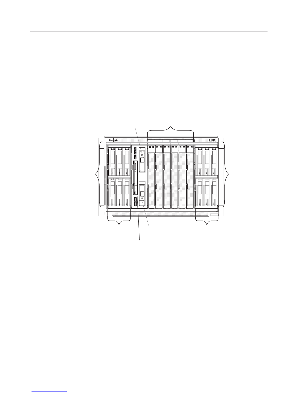
Front view of the BladeCenter S chassis
Blade servers, storage modules, and the media tray are installed in the front of the
BladeCenter S chassis.
Note: For proper cooling, each bay in the BladeCenter S chassis must have either a
device or a filler installed.
The following illustration shows the front of the BladeCenter S chassis.
Battery backup
unit 1
Blades
Storage
module
1
SAS/SATA
hard disk drives
Media tray
Battery backup
unit 2
SAS/SATA
hard disk drives
Storage
module
2
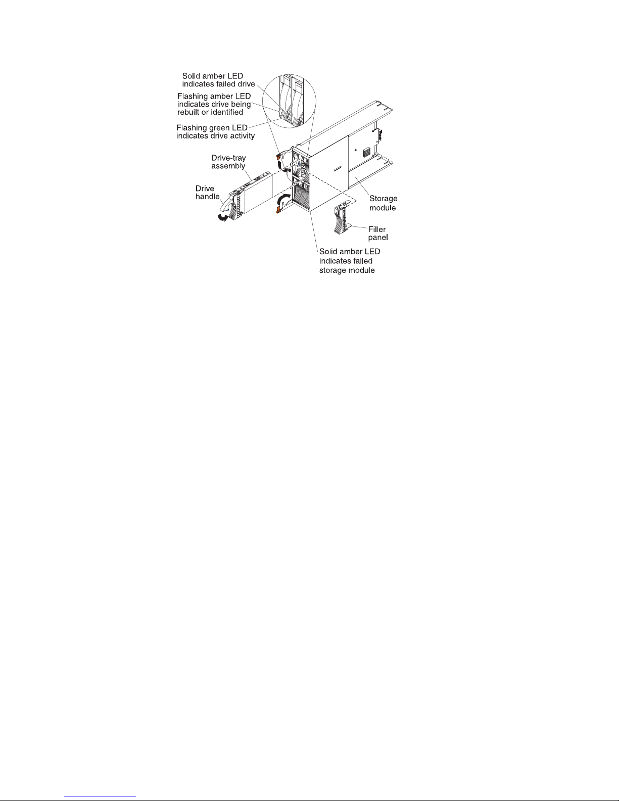
Storage modules
You can install a maximum of two storage modules in the BladeCenter S chassis
and each storage module contains hot-swap hard disk drives. A storage module
and the hard disk drives installed in that storage module are commonly referred to
as integrated shared storage because this storage is integrated in the BladeCenter S
chassis and shared among the blade servers in the BladeCenter S system.
Each storage module can support up to six hot-swap, 3.5-inch hard disk drives. If
you are installing SAS connectivity modules, both SAS and SATA hard disk drives
are supported, and you can use both types of hard disk drives in each storage
module. If you are installing SAS RAID controller modules, you must install SAS
hard disk drives.
Within each storage module, hard disk drives are numbered 1 through 6 from left
to right, and top to bottom.
Note: Each hard disk drive bay must contain either a hard disk drive or a
drive-bay filler.
6 BladeCenter S Type 7779/8886: Planning Guide
Page 13
Note: Four power modules are required in the BladeCenter S chassis if both
storage modules are installed.
To access the hard disk drives in the storage module, the following devices must
be installed:
v SAS I/O modules. You can choose to install either SAS connectivity modules or
SAS RAID controller modules.
Note: You cannot mix these module types in the same BladeCenter S chassis.
– SAS connectivity module. At least one SAS connectivity module must be
installed. If a single SAS connectivity module is installed, it controls access to
both storage modules in the BladeCenter S chassis. If two SAS connectivity
modules are installed, the module in I/O module bay 3 controls access to
storage module 1, and the module in I/O module bay 4 controls access to
storage module 2.
– SAS RAID controller module. Two SAS RAID controller modules must be
installed, one in I/O module bay 3 and the other in I/O module bay 4. Each
SAS RAID controller module will have access to both storage modules (for
high availability).
v A SAS expansion card in each of the blade servers, which provides access
through the SAS I/O modules in I/O module bays 3 and 4 to the SAS or SATA
hard disk drives in each storage module.
There is one LED on each storage module:
Fault Solid (amber) when there is a storage module failure.
Chapter 1. Introduction 7
Page 14
There are two LEDs on each hard disk drive:
Green Flashing when an operation, such as a read or a write, is being performed.
Amber
Flashing when the hard disk drive is being rebuilt (fast blink) or identified
(slow blink).
Note: When power is restored to the BladeCenter S chassis after a
complete loss of power and you have implemented the hard disk drives as
a mirrored array, the fault light will blink as the hard disk drive is being
resynchronized.
This resynchronization occurs because the blade servers are attempting to
power on before all of the storage modules and SAS connectivity modules
are powered up and available. The mirrored array is accessible during
resynchronization although performance may be slightly slower.
Solid when there is a drive failure.
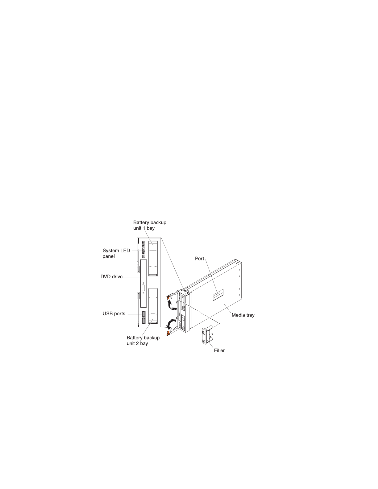
Media tray
The media tray contains the DVD drive (which can be either a CD-RW/DVD-ROM
drive or a DVD/RW drive) and two USB v2.0 ports, which are shared by the blade
servers. The media tray also contains two battery backup units, which provide
backup for SAS RAID controller modules cache
Note: The port on the side of the media tray is reserved for future use.
8 BladeCenter S Type 7779/8886: Planning Guide
Page 15
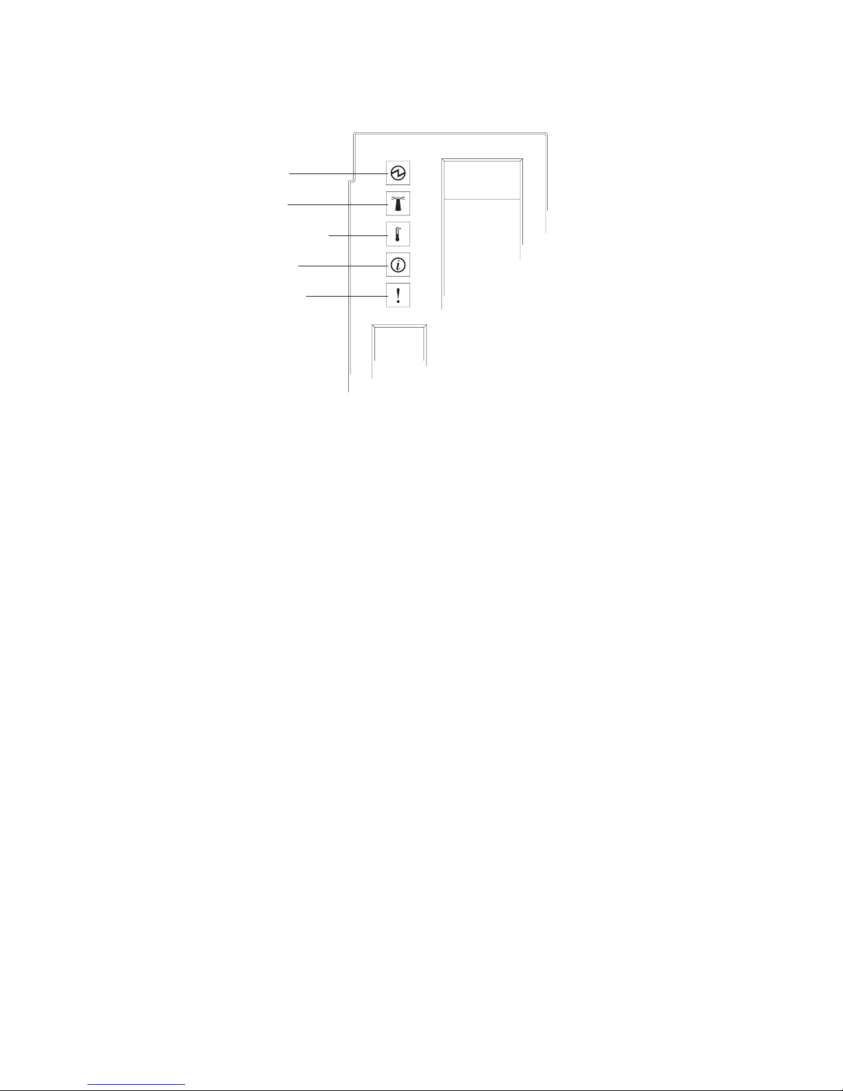
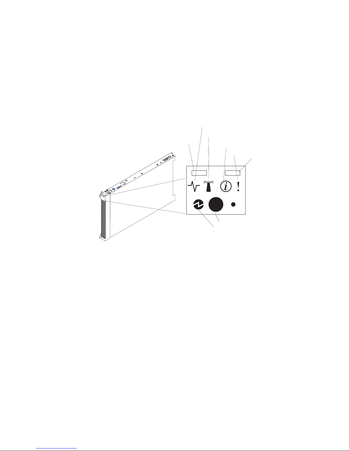
Controls and indicators
Power-on
Location
Over-temperature
Information
System error
The media tray provides the following controls and indicators:
System LED panel
The LEDs on this panel provide status information for the BladeCenter S
chassis.
Note: These LEDs are also displayed on the rear of the BladeCenter S
chassis.
Power-on
Lit (green). Power is being supplied to the BladeCenter S chassis.
Off. The power subsystem, ac power, or the LED has failed.
Note: Even if the power-on LED is off, always remove the power
cords from all power modules before you service the BladeCenter S
chassis.
Location
Lit or flashing (blue). It has been turned on by the system
administrator to aid in visually locating the BladeCenter S chassis.
You can turn off the location LED throught the Web interface or
the IBM Director console.
Over-temperature
Lit (amber). The temperature in the BladeCenter S chassis exceeds
the temperature limits, or a blade server reports an
over-temperature condition. The BladeCenter S chassis might have
already taken corrective action, such as increasing the fan speed.
This LED turns off automatically when there is no longer an
over-temperature condition.
Information
Lit (amber). A noncritical event has occurred that requires
attention, such as the wrong I/O module being inserted into a bay,
or power demands within the BladeCenter S chassis exceeding the
capacity of the installed power modules.
Chapter 1. Introduction 9
Page 16
You can turn off the information LED through the Web interface or
the IBM Director console.
System error
Lit (amber). A system error has occurred, such as a module failure
or a system error in a blade server. An LED on the failing
component is also lit to assist in isolating the error.
DVD drive activity LED
Lit (green). The drive is in use.
DVD drive eject button
Press this button to open the DVD drive.
USB ports
Connect USB devices to these ports.
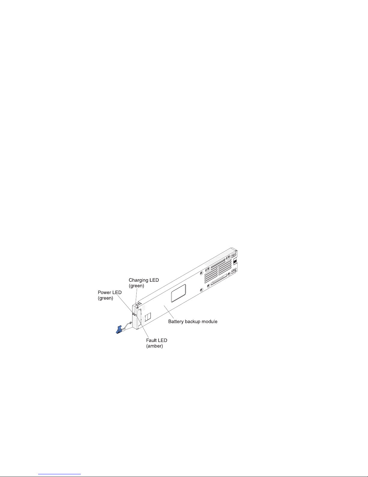
Battery backup unit:
Battery backup units provide backup for SAS RAID controller modules cache.
Battery backup units are installed in the battery backup unit bays located in the
media tray when you install SAS RAID controller modules. The battery backup
unit in battery backup bay 1 provides backup support for the SAS RAID controller
module in I/O module bay 3; the battery backup unit in battery backup bay 2
provides backup support for the SAS RAID controller module in I/O module bay
4.
Note: Both battery backup units are required if you install SAS RAID controller
modules.
Controls and indicators
The battery backup unit provides the following indicators:
Power Lit (green). Power is being supplied to the battery backup unit.
Charging
Lit (green). The battery backup unit is being charged.
Fault Lit (amber). The battery backup unit has a failure. If the Fault LED is lit,
replace the battery backup unit.
10 BladeCenter S Type 7779/8886: Planning Guide
Page 17
Blade server
Blade servers can contain components such as microprocessors, memory, Ethernet
controllers, and hard disk drives. They receive power, network connection, and
I/O devices (such as DVD drive, keyboard, mouse, video port, USB ports, and a
remote monitoring port) from the BladeCenter S chassis.
A SAS expansion card must be installed in each blade server that will access the
integrated shared storage.
Note: The control panel door is shown in the closed position in the following
illustration. To access the power-control button, you must open the control panel
door.
Activity LED
Location LED
KVM select button
Information LED
Blade-error LED
Media-tray select
button
Power-control button
Power-on LED
You can find the documentation for blade servers in the IBM Systems Information
Center, which is at http://publib.boulder.ibm.com/infocenter/systems/index.jsp.
To access the blade server documentation from this site, click Systems hardware →
BladeCenter information → Blade servers.
To determine which blade servers are compatible with the BladeCenter S chassis,
see the IBM ServerProven Web site at http://www.ibm.com/servers/eserver/
serverproven/compat/us/eserver.html.
Controls and indicators
Blade servers typically provide the following controls and indicators:
KVM select button
Activity LED
Location LED
When using an operating system that supports a local console and
keyboard, press this button to associate the shared BladeCenter S chassis
keyboard and video ports with the blade server.
When this green LED is lit, it indicates that there is activity on the hard
disk drive or network.
When this blue LED is lit, it has been turned on by the system
administrator to aid in visually locating the blade server. The location LED
Chapter 1. Introduction 11
Page 18

can be turned off through the Web interface of the advanced management
module or through the IBM Director Console.
Information LED
When this amber LED is lit, it indicates that information about a system
error for the blade server has been placed in the advanced management
module event log. The information LED can be turned off through the Web
interface of the advanced management module or through the IBM
Director console.
Blade-error LED
When this amber LED is lit, it indicates that a system error has occurred in
the blade server. The blade-error LED will turn off after one of the
following events:
v Correcting the error
v Reseating the blade server in the BladeCenter S chassis
v Cycling the BladeCenter S chassis power
Media-tray select button
Press this button to associate the shared BladeCenter S chassis media tray
(removable-media drive and front-panel USB ports) with the blade server.
The LED on the button flashes while the request is being processed, then is
lit when the ownership of the media tray has been transferred to the blade
server. It can take approximately 20 seconds for the operating system in
the blade server to recognize the media tray.
If there is no response when you press the media-tray select button, use
the advanced management module to determine whether local control has
been disabled on the blade server.
Power-control button
This button is behind the control panel door. Press this button to turn on
or turn off the blade server.
The power-control button has effect only if local power control is enabled
for the blade server. Local power control is enabled and disabled through
the Web interface of the advanced management module.
Press down the power button for five seconds to begin powering down the
blade server.
Power-on LED
This green LED indicates the power status of the blade server in the
following manner:
v Flashing rapidly: The service processor (BMC) is initializing the blade
server.
v Flashing slowly: The blade server has completed initialization and is
waiting for a power-on command.
v Lit continuously: The blade server has power and is turned on.
12 BladeCenter S Type 7779/8886: Planning Guide
Page 19
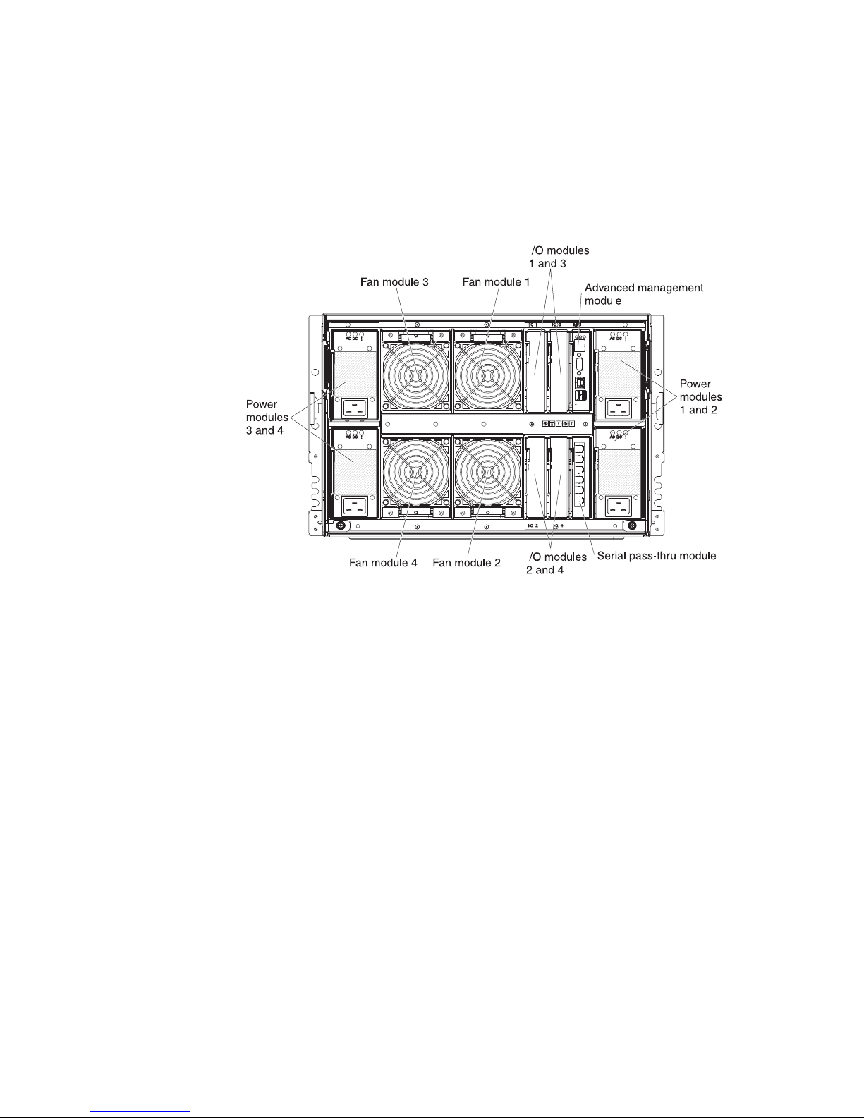
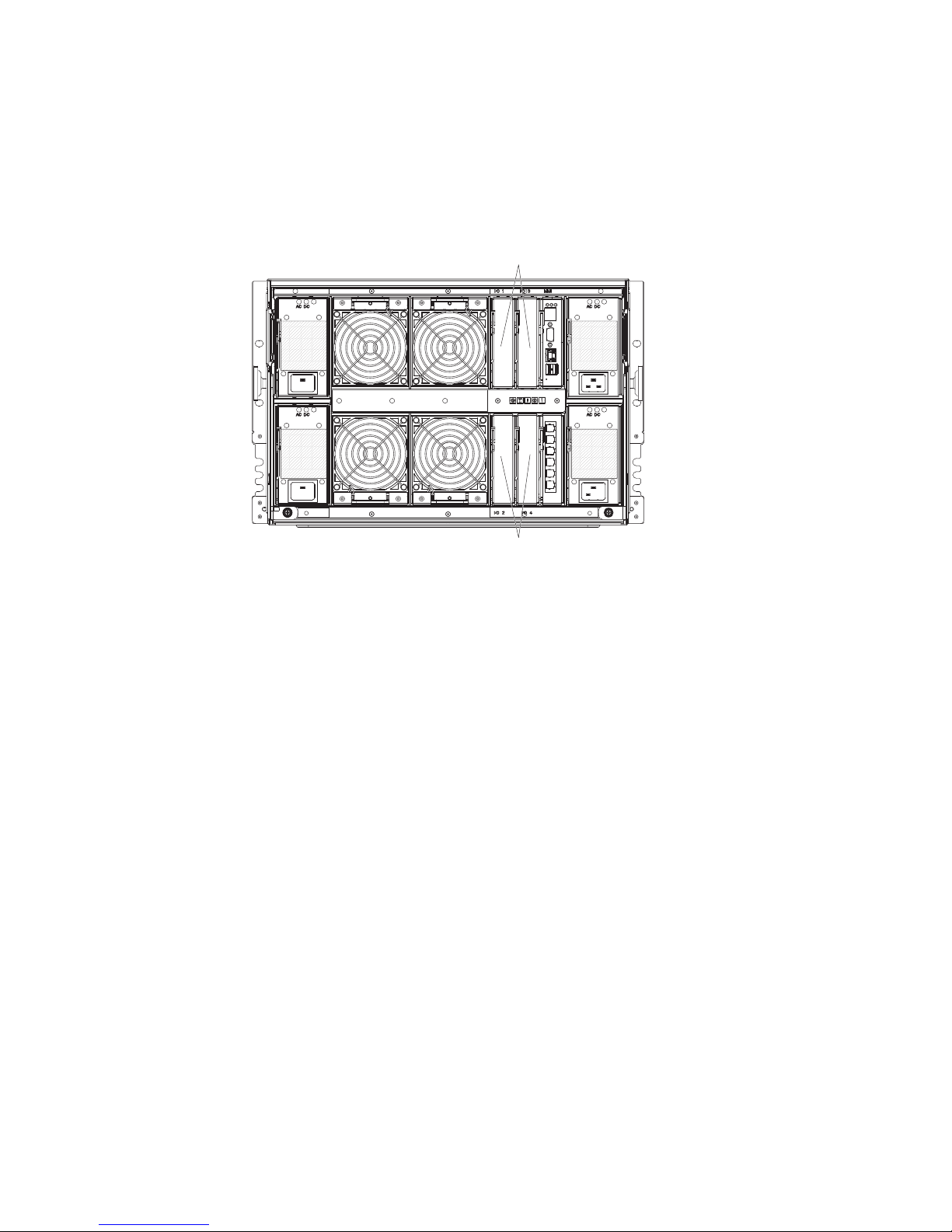
Rear view of the BladeCenter S chassis
Fan modules, I/O modules, power modules, the advanced management module,
and the serial pass-thru module are in the rear of the BladeCenter S chassis.
Note: Each bay in the BladeCenter S chassis must have either a device or a filler
installed.
The following illustration shows the rear of the BladeCenter S chassis.
Advanced management module
The advanced management module is a hot-swap module that you use to
configure and manage all installed BladeCenter components. The BladeCenter S
chassis comes with one advanced management module in the advanced
management module bay.
The advanced management module provides systems-management functions and
keyboard/video/mouse (KVM) multiplexing for all blade servers in the
BladeCenter S chassis that support KVM. It controls the following connections:
v A serial port for a local connection to another computer, such as a notebook
computer
v The external video and USB connections for keyboard and mouse
v A 10/100 Mbps Ethernet connection
The advanced management module communicates with the service processor (also
called the baseboard management controller, or BMC) in each blade server to
support features such as blade server power-on requests, error and event reporting,
KVM requests, and requests to use the BladeCenter S chassis shared media tray.
Chapter 1. Introduction 13
Page 20
Activity LED
Power-on LED
Serial
Console
OK
Error LED
Video
Port link LED
Ethernet
LINK
TX/RX
Port activity LED
USB
MAC
address
Release handle
The BladeCenter S chassis supports a single advanced management module, and it
must be installed in the advanced management module bay.
Advanced management module indicators and controls:
The advanced management module has several LEDs that you can use to obtain
status about the advanced management module and the Ethernet connection.
Power-on
LED
Activity
LED
Error
LED
OK
Port link LED
LINK
TX/RX
Port activity LED
Release handle
The following advanced management module LEDs provide status information
about the advanced management module and Ethernet connection:
14 BladeCenter S Type 7779/8886: Planning Guide
Reset
Page 21
Power-on
Lit (green). The advanced management module has power.
Activity
Lit (green). The advanced management module is actively controlling the
BladeCenter S system.
Error Lit (amber). An error has been detected in the advanced management
module. When the error LED is lit, the BladeCenter system error LED is
also lit.
Port Link
Lit (green). There is an active connection through the Ethernet port to the
network.
Port activity
Flashing (green). There is activity through the Ethernet port over the
network link.
Reset
Insert a straightened paper clip into the reset pinhole and remove it to restart the
advanced management module. The fan modules operate at full speed while the
advanced management module is initializing.
Attention: If you push the paper clip in all the way and hold it for approximately
10 seconds, the advanced management module will be reset to the default
configuration. Therefore, you should always make sure that you save your current
configuration before resetting the advanced management module.
For more information about saving and restoring configurations, see the IBM
BladeCenter Advanced Management Module User's Guide.
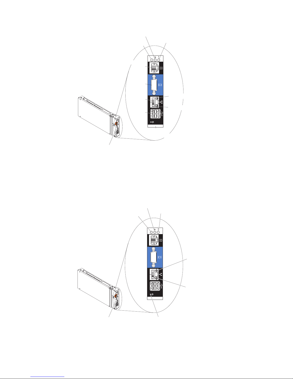
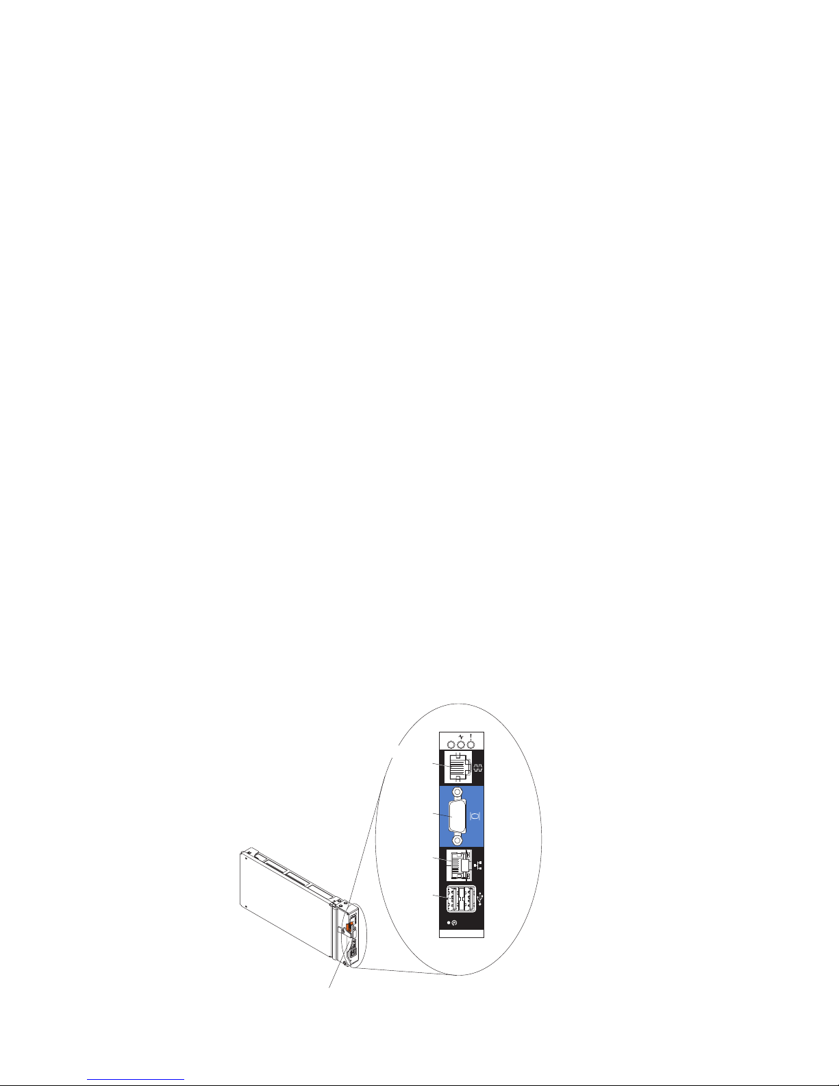
Advanced management module input and output connectors:
The advanced management module has a serial connector, a video connector, two
USB connectors for keyboard and mouse, and an Ethernet connector for remote
management.
OK
Serial
Console
Video
Ethernet
USB
LINK
TX/RX
Release handle
Chapter 1. Introduction 15
Page 22

Serial Console
Use this connection to configure and manage the BladeCenter components
through the advanced management module command-line interface (CLI).
For example, you can connect a notebook computer to the serial connector
and use a terminal emulator program to configure the IP addresses, user
accounts and other settings.
The serial pinout for the advanced management module is an EIA-561, as
shown in the following table:
Contact (pin number) Signal name
1 DSR (Data set ready)
2 DCD (Data carrier detect)
3 DTR (Data terminal ready)
4 GND (Ground)
5 Receive (RX)
6 Transmit (TX)
7 CTS (Clear to send)
8 RTS (Request to send)
Video Use this connector to connect a compatible SVGA or VGA video monitor to
the BladeCenter S system.
Ethernet
Use this connector to connect the BladeCenter S system to a the
management station, either through an Ethernet cable or on the network.
USB connectors
Use these connectors to connect a mouse and keyboard (or other USB
devices). Unlike the USB connectors on the media tray, these connectors are
shared by the blade servers through the BladeCenter Keyboard, Video,
Mouse (KVM) interface. The KVM interface owns these ports.
Note: If you connect a USB storage device to these connectors, the blade
server has ownership of the media tray and can access the device. To
switch ownership of the media tray to a specific blade server, press the
CD
button on that blade server.
Serial pass-thru module
The serial pass-thru module has six serial ports that you can use to directly attach
a four-wire serial RJ-45 connector to each of the blade servers in the BladeCenter S
chassis. If you use the serial pass-thru module, it must be installed in the serial
pass-thru module bay.
Note: See the documentation for the blade server that you are using to ensure that
it supports this type of serial access.
The connectors are numbered 1 through 6, from top to bottom, and correspond to
blade servers in blade server bays 1 through 6.
16 BladeCenter S Type 7779/8886: Planning Guide
Page 23
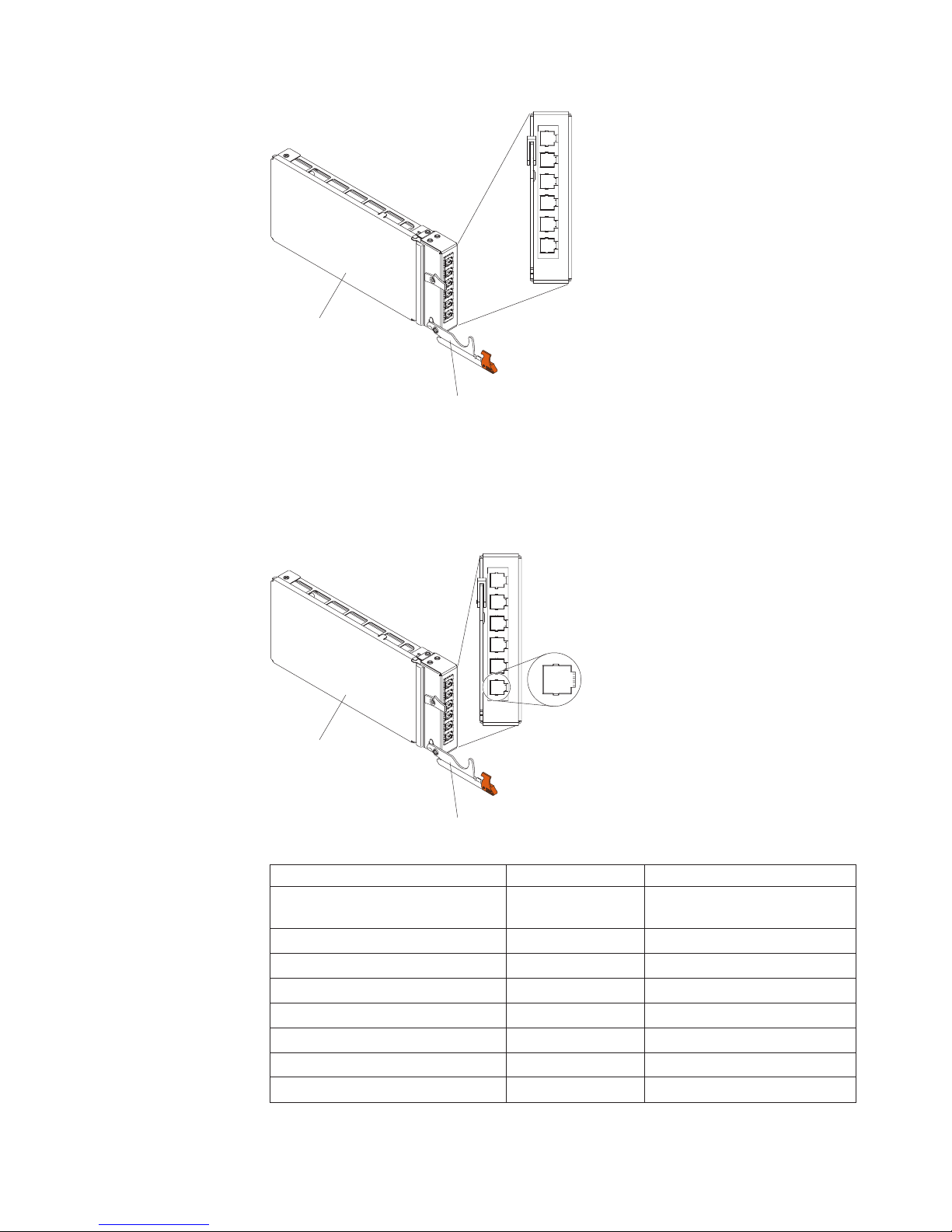
Serial
pass-thru
module
Release
handle
Serial pass-thru connector pinout
There are eight pins on each RJ-45 port, numbered 1 through 8, from bottom to
top.
8
1
Serial
pass-thru
module
Contact (pin number) Signal name Signal direction
1 RTS (Request to
2 Not used n/a
3 RXD (Receive data) Input to blade server
4 GND (Ground) n/a
5 Not used n/a
6 TXD (Transfer data) Output from blade server
7 Not used n/a
8 CTS (Clear to send) Input to blade server
Release
handle
Output from blade server
send)
Chapter 1. Introduction 17
Page 24
Note: The serial pass-thru module uses the DTE convention.
I/O modules
You can install up to four I/O modules in the BladeCenter S chassis, including
Ethernet switch modules, Fibre Channel switch modules, pass-thru modules
(optical and copper), SAS connectivity modules, and SAS RAID controller modules.
I/O modules
1 and 3
! !
! !
I/O modules
2 and 4
Note:
You can find the documentation for I/O modules at the IBM Systems Information
Center, which is at http://publib.boulder.ibm.com/infocenter/systems/index.jsp.
To access the I/O module documentation from this site, click Systems hardware →
BladeCenter information → I/O modules.
To determine which I/O modules are compatible with the BladeCenter S chassis,
see the IBM ServerProven Web site at http://www.ibm.com/servers/eserver/
serverproven/compat/us/eserver.html.
I/O module bay 1
I/O module bay 1 supports any standard Ethernet or pass-thru module that
connects to the two integrated Ethernet controllers in each of the blade servers.
Note: This I/O module bay is wired differently from I/O module bay 1 in a
BladeCenter E or BladeCenter H chassis.
18 BladeCenter S Type 7779/8886: Planning Guide
Page 25

I/O module bay 2
I/O module bay 2 supports an optional I/O module, such as an Ethernet switch or
a pass-thru module, that connects to the two integrated Ethernet controllers in each
of the blade servers.
Note: If you install an I/O module in I/O module bay 2, you will also need to
install an expansion card option, such as the 2/4 Port Ethernet Expansion Card, in
each blade server that will access the external Ethernet network through the switch
module in I/O module bay 2.
I/O module bays 3 and 4
I/O module bays 3 and 4 support SAS connectivity modules or SAS RAID
controller modules.
v If you are using the RAID storage solution, you must install two SAS RAID
controller modules, one in I/O module bay 3 and one in I/O module bay 4. SAS
RAID controller modules require a SAS expansion card option in each blade
server that will access the integrated shared storage.
v If you are using only one SAS connectivity module, install the module in I/O
module bay 3. You can install an additional SAS connectivity module in bay 4. A
SAS connectivity module requires a SAS expansion card option in each blade
server that will access the integrated shared storage.
The two bays also support Ethernet switch modules, Fibre Channel switch
modules, and pass-thru modules (optical and copper) if the storage modules are
not being used.
Important: I/O module bays 3 and 4 must both contain the same type of switch
(either SAS connectivity modules, SAS RAID controller modules, Ethernet switch
modules, pass-thru modules, or Fibre Channel switch modules).
Power modules
The BladeCenter S system supports up to four autoranging power modules that
are capable of supporting either 110 V ac or 220 V ac.
Chapter 1. Introduction 19
Page 26
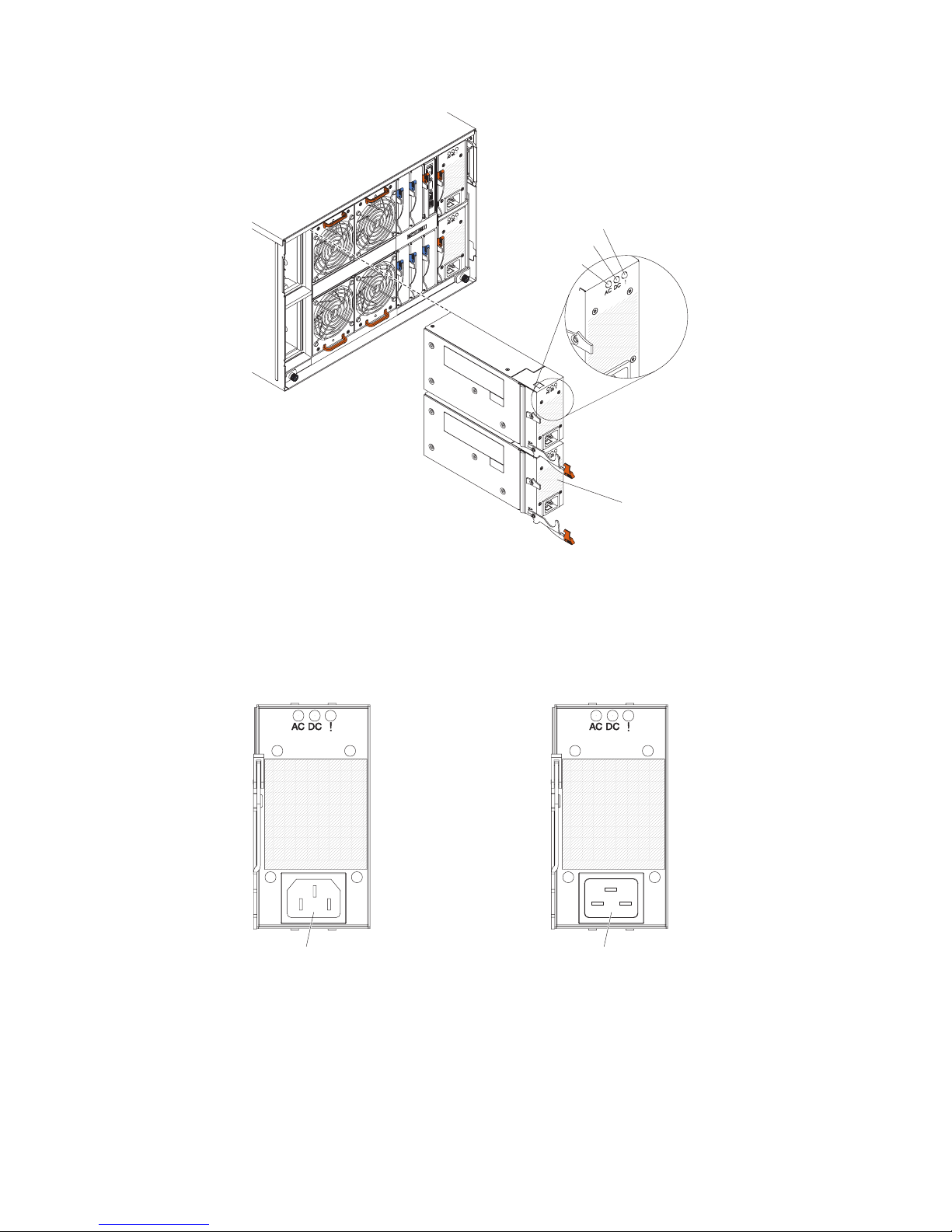
Fault LED
DC power LED
AC power LED
Power module
There are two types of power modules. These power modules are identical except
for the power cord connector; one power module has a C14 connector and the
other power module has a C20 connector. Both types of power modules can be
installed in the same chassis.
Table 1. Power modules used in the BladeCenter S system
Power module with C14 connector
Power module with C20 connector
C14 connector
Within the BladeCenter S chassis, all power supplies are combined into a single
power domain, which distributes power to each of the blade servers and modules
through the system midplane.
You must install a minimum of two power modules. If you install only two power
modules, install them in power module bays 1 and 2 (the top and bottom power
module bays on the right as you face the rear of the BladeCenter S chassis).
20 BladeCenter S Type 7779/8886: Planning Guide
C20 connector
Page 27

Note: You must install all four power modules if you are using both storage
modules.
If you disengage or remove all devices from the front of the BladeCenter S chassis
(media tray, blade servers, and storage modules), the power modules will be
disabled.
Indicators and controls
There are three LEDs on each power module:
AC power
Lit (green). Power is being supplied to the power module.
DC power
Lit (green). Power is being supplied from the power module to the
BladeCenter S chassis midplane.
Fault Lit (amber). There is a fault with the power module.
Note: Before unplugging the AC power cord from the power module or
removing the power module from the BladeCenter S chassis, verify that the
capacity of the remaining power modules are sufficient to meet the
minimum power requirements for all components in the BladeCenter S
chassis. You can view power status and requirements through the
advanced management module.
For information on accessing and using the advanced management
module, see the Advanced Management Module User's Guide.
1. Verify that the power modules are properly connected to an AC power
source. All power modules in the BladeCenter S chassis must be
connected to the same power input voltage (either 110 V ac or 220 V
ac). Do not mix power input voltages.
2. Unplug the AC power cord from the power module and plug it in
again.
3. Reseat the power supply.
4. Swap the AC power cord with a power cord that is known to be
working.
5. Move the power module to another power module bay in the
BladeCenter S chassis.
Fan modules
The BladeCenter S chassis comes with four installed hot-swap fan modules.
The fan modules (sometimes called fan packs) are designed to provide cooling
airflow to the blade servers and I/O modules. Each fan module contains two fans.
Chapter 1. Introduction 21
Page 28
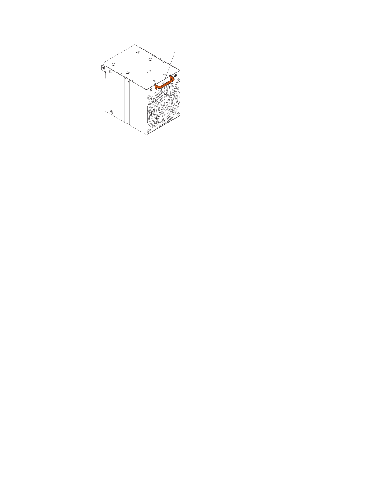
Fan error LED
Indicators and controls
Each fan module has a single LED:
Error Lit (amber). One of the fans in the fan module has failed.
Note: If one of the fans in the fan module fails, the other fan will begin
operating at full speed.
Systems and storage management
IBM provides products that you can use to manage your BladeCenter S system and
the integrated shared storage that is available.
IBM Director
IBM Director provides a comprehensive entry-level workgroup hardware manager.
It includes advanced self-management capabilities for maximum system
availability and support for multiple operating systems, including Microsoft
Windows, AIX, Linux, and i5/OS.
With IBM Director, a systems or network administrator can perform the following
tasks:
v View and modify the hardware configuration of remote systems
v Monitor the usage, health, and performance of critical components, such as
microprocessors, disks, and memory
v Centrally manage individual or large groups of IBM and non-IBM
x86-processor-based servers, desktop computers, workstations, and notebook
computers on a variety of platforms
v Inventory your environment
v Perform updates to managed systems, such as device drivers and firmware
v Automatically perform an action based on events or schedules, if IBM Director is
configured to do so
By deploying IBM Director, you can achieve reductions in ownership costs through
the following benefits:
v Reduced downtime
v Increased productivity of IT personnel and users
v Reduced service and support costs
22 BladeCenter S Type 7779/8886: Planning Guide
Page 29

For more information about IBM Director and to download the latest version of
IBM Director, go to http://www.ibm.com/systems/management/director/.
Storage Configuration Manager
Storage Configuration Manager is a Web based device management application.
Storage Configuration Manager provides user and programmatic interfaces that
you need to configure and monitor multiple instances of different types of storage
related devices, including either the SAS connectivity modules or the SAS RAID
controller modules, and the SAS controllers on the expansion cards in each blade
server. It includes a Web-based graphical user interface. It can be installed as a
stand-alone application or as an extension to IBM Director 5.20.2.
You can connect to the Storage Configuration Manager Manager component of the
application from any computer on the network that it is installed on, using a
standard Web browser (Internet Explorer 6.x or later, Firefox 1.0 or later).
Instead of using Storage Configuration Manager, you have the option of
configuring the integrated shared storage from the configuration wizard of the
advanced management module if you choose one of the predefined configurations
that are provided. However, you must install Storage Configuration Manager if
you decide to modify an existing configuration or create your own customized
configuration.
To download Storage Configuration Manager go to http://www.ibm.com/
systems/support/management and select IBM Storage Configuration Manager.
Chapter 1. Introduction 23
Page 30

24 BladeCenter S Type 7779/8886: Planning Guide
Page 31

Chapter 2. Planning for the physical environment
Make sure that the site where the BladeCenter unit will be installed meets the
minimum physical requirements for rack, power, and cooling.
Dimensions
A BladeCenter S chassis is 7 rack units (7 U) high.
A BladeCenter S chassis has the following dimensions:
Width: 444 mm (17.5 inches)
Height: 306.3 mm (12 inches)
Depth: 733.4 mm (28.9 inches) from front of the chassis to the rear
Weight considerations
Floors and racks have maximum weight loads. Take these loads into consideration
when planning your floor space.
The fully configured weight with blade servers is approximately 108.86 kg (240
lbs).
The empty chassis without modules or blade servers weighs approximately 40.82
kg (90 lbs).
Floor space
The required floor space must allow enough clearance in the front and rear of the
rack so that the doors can be opened to access the equipment.
Front clearance is needed to access the blade servers, storage modules, and the
media tray. Rear clearance is needed to access power supplies, fans, and network
cable connections, as well as to attach a local monitor, keyboard, and mouse to the
advanced management module. The following graphic shows the maximum
operational clearances for IBM NetBAY racks and expansion units that are
recommended for use with BladeCenter systems.
Note: Some racks, such as the IBM S2 25U Standard Rack and the IBM S2 42U
Standard rack have dual doors and take up less space.
© Copyright IBM Corp. 2007, 2010 25
Page 32

914mm
36"
3438mm
136"
If you are using the Office Enablement Kit, see the IBM BladeCenter Office
Enablement Kit Installation and User's Guide.
Rack requirements
Make sure the rack in which you are going to install the BladeCenter S chassis
meets these minimum requirements.
v Make sure that the room air temperature is below 35°C (95°F).
v Do not block any air vents; usually, 15 cm (6 in.) of air space in the rear and 5
cm (2 in.) in the front provides proper airflow.
v Three or more people are required to install the device in a rack.
v Do not leave any unused U space within a rack open. Blank filler panels must
be used to prevent recirculation of warm air.
v Install your BladeCenter S chassis only in a rack cabinet with perforated front
and rear doors or in a rack equipped with the IBM Rear Door Heat eXchanger.
v Do not extend more than one device out of the rack at the same time.
v Remove the rack doors and side panels to provide easier access during
installation.
v The rack-mounting flanges have holes and clearances per EIA-310-D.
v There is sufficient room in front of the front EIA flange to provide minimum
bezel clearance of 70 mm (2.76 inches) deep.
v There is sufficient room behind the rear of the rear EIA flanges to provide for
adequate cable management and routing.
v Rack weight-handling capacity must be sufficient for the aggregate weight of the
BladeCenter S chassis, blade servers, power distribution units, and power cables.
v The rack needs to be stabilized with stabilization brackets and leveling pads so
that it does not become unstable when fully loaded.
NetBay
Rack C
NetBay
Rack B
Front
3850mm
152"
NetBay
Rack A
1524mm
60"
Important: When moving a 42U rack, remove all equipment installed above 22U
before moving the rack to another location.
26 BladeCenter S Type 7779/8886: Planning Guide
Page 33

IBM and non-IBM racks
Verify that you are not exceeding the maximum weight load limits for IBM and
non-IBM racks.
Table 2 shows the maximum weight limits for IBM NetBAY racks and expansion
units that are recommended for use with BladeCenter S chassis. The table shows
the maximum number of BladeCenter S chassis that can be installed in a NetBAY
rack when the rack is:
v Installed in place and sitting on the rack leveling pads.
v Being relocated and is sitting on the rack castors.
For on-site relocation of the rack on castors, the maximum number of BladeCenter
S chassis, including the power distribution units (PDUs) to support the
configuration, is based on a 14-degree stability requirement established under IBM
safety guidelines.
Table 2. Rack weight load limits
Rack Rack weight Maximum
Office
Enablement Kit
NetBAY 11 37 kg (75 lb) 216 kg (475 lb) 1 1
NetBAY 42
Enterprise Rack
NetBAY 42
Enterprise
Expansion
Cabinet
NetBAY 42
Standard Rack
NetBAY 42
Standard
Expansion
Cabinet
NetBAY 25
Standard Rack
NetBay S2 25
Standard Rack
NetBay S2 42
Standard Rack
40.8 kg (90 lb) 223 kg (491 lb) 1 1
261 kg (575 lb) 928 kg (2045 lb) 6 3
234 kg (511 lb) 928 kg (2045 lb) 6 3
119 kg (262 lb) 765 kg (1683 lb) 6 3
112 kg (246 lb) 739 kg (1626 lb) 6 3
95 kg (209 lb) 466 kg (1025 lb) 3 3
100 kg (221 lb) 667 kg (1471 lb) 3 3
125 kg (275 lb) 1032 kg (2275 lb) 6 6
allowable rack
weight load
Maximum
number of fully
loaded
BladeCenter S
units with rack
on leveling pads
or bolted to the
floor
On-site
relocation, rack
on casters,
maximum
number of
BladeCenter S
units
When determining your floor load limits, use the combined weight of the rack,
populated BladeCenter S chassis, PDUs, and other rack mounting hardware to
ensure the installation site can safely support the total weight. Consult your local
building engineer to understand the weight limits for your site. Use the “Rack
installation worksheet” on page 87 to record your information.
Chapter 2. Planning for the physical environment 27
Page 34

Noise considerations
Each BladeCenter S chassis has four fan modules for cooling and each fan module
has 2 fans. The fan modules generate measurable noise.
The sound levels for the BladeCenter S chassis range from 6.3 bels to 6.8 bels
depending on the number and type of blade servers that are installed.
The actual sound-pressure levels in your installation depend on a variety of
factors, including the number of servers in the installation, the size, materials, and
configuration of the room where the servers are installed, the noise levels from
other equipment, the room ambient temperature, and employees' location in
relation to the equipment.
Your server installation may be subject to government regulations, such as those
prescribed by OSHA or European Community Directives, that cover noise-level
exposure in the workplace. Consult a qualified person, such as an industrial
hygienist, to determine the sound-pressure levels to which your employees are
exposed.
Power considerations
When planning for power, you need to determine how many power modules you
intend to install (either 2 or 4) and whether they are going to be connected to 110
V ac or 220 V ac power sources. In addition, you need to determine the type of
power management policy that you intend to implement.
The power modules for the BladeCenter S system can accept either low voltage
range (110 V ac nominal) or high voltage range (220 V ac nominal) line input from
your power utility distribution network.
At a minimum, you need to install two power modules, and they must be installed
in power module bays 1 and 2. These power modules will provide power to the
following components:
v Blade server bays 1 through 6
v I/O module bays 1 through 4
v Advanced management module module bay
v Serial Pass-Thru Module module bay
v Storage module bay 1
v Fan module bays 1 through 4
If you are going to install a storage module in bay 2, you will also need to install
two additional power modules in power module bays 3 and 4. In addition, the
configuration of the blade servers that you have installed might require that you
installed additional power modules.
In addition to this information, you can use the IBM System x and BladeCenter
Power Configurator at http://www.ibm.com/systems/bladecenter/powerconfig/
to assist in planning for power.
28 BladeCenter S Type 7779/8886: Planning Guide
Page 35

Power source requirements
The BladeCenter S system can run on either 110 V ac or 220 V ac. Each of the four
power supplies in the BladeCenter S chassis is capable of handling either type of
power source.
Note: Although the power modules are autoranging and can support either 110 V
ac or 220 V ac, you cannot mix voltage power sources within the same BladeCenter
S system. All power modules within a BladeCenter S system must be connected to
either a 110 V ac or 220 V ac power sources.
AC power input must be adequate to supply the required voltage and amperage at
an input frequency range from 50-60 hertz (Hz). The BladeCenter S system requires
the following ac input voltage:
Table 3. ac input voltage requirements
Nominal Voltage Minimum Voltage Maximum Voltage
110 V ac 100 127
220 V ac 200 240
The ac input current requirements are shown in the following table:
Table 4. ac input current requirements
Nominal Voltage Nominal Amps Maximum Continuous Amps
100 V ac 11.2 13.9
200 V ac 8.0 9.0
Power consumption guidelines
The BladeCenter S system is configurable with varying numbers of some
individual components. As you add components to the BladeCenter S system, the
power consumption increases.
Blade servers, fan modules, SAS or SATA drives, and other components all
contribute to the power footprint. A BladeCenter S system can have a minimum of
two or a maximum of four power supply modules that must provide the 12-volt
power for all of the components that you are including in the chassis.
Table 5. Power consumption of BladeCenter S system components
Component Maximum Watts
Midplane 5W
Media tray 7.5W
Fans (four) 240W
Advanced management module 25W
Power module fans (two power modules) 20W
I/O module 45W
SAS connectivity module 65W
SAS RAID controller module 65W
Battery backup unit 10W
Storage module 120W
Chapter 2. Planning for the physical environment 29
Page 36

Table 5. Power consumption of BladeCenter S system components (continued)
Component Maximum Watts
Serial pass-thru module
Note: Power for the serial pass-thru module is provided by
the blade servers.
The maximum wattage requirement for blade serves varies depending on the type
of blade server installed in the BladeCenter S system. For the latest information
related to power consumption and requirements for blade servers, see the IBM
System x and BladeCenter Power Configurator at http://www-03.ibm.com/
systems/bladecenter/powerconfig/.
Power management policies
You can set the power management policy to be used for the BladeCenter S system
from the advanced management module.
You can choose from the following power management policies:
v AC power source redundancy
With this policy, the total allowable power draw is limited to the capacity of two
power modules. If you use dual ac power sources, one ac power source can fail
without affecting the operation of the blade servers. However, some blade
servers may not be able to power on if doing so will exceed the power policy
limit.
The policy is intended for use when you have four power modules installed and
two separate 220-volt AC power sources.
v AC power source redundancy with blade throttling allowed
This policy is similar to AC power source redundancy. With this policy, the total
allowable power draw is limited to the capacity of two power modules. If you
use dual ac power sources, one ac power source can fail without affecting the
operation of the blade servers.
If power module redundancy is lost, processors on blade servers that are capable
of throttling will throttle to reduce the power consumed to less than or equal to
the total power. Throttling refers to achieving lower power consumption for a
blade by temporarily reducing the CPU throughput. The advanced management
module utilizes power management technologies built into certain processors to
throttle the blades.
0W
Note: Not all blade servers are capable of throttling.
The policy is intended for use when you have four power modules installed and
two separate 220-volt AC power sources.
v Power module redundancy
With this policy, the total allowable power draw is limited to one less than the
number of power modules when more than one power module is present. One
power module can fail without affecting blade server operation.
Blade servers will power on only if they can operate without throttling if there is
a power module failure. The number of blade servers allowed to power on is
determined by the power available from one less than the total number of
power modules. If a single power module fails, all the blade servers that are
powered on will continue to operate at normal performance levels. If two or
more power modules fail, the BladeCenter S chassis could power off.
30 BladeCenter S Type 7779/8886: Planning Guide
Page 37

This policy is intended when you have two to four power modules installed and
a single 110-volt or 220-volt AC power source. Each power module is on its own
dedicated circuit.
v Power module redundancy with blade throttling allowed
With this policy, the total allowable power draw is limited to one less than the
number of power modules when more than one power module is present. One
power module can fail without affecting blade server operation, but multiple
power module failures can cause the chassis to power off.
This policy allows you to draw more total power from the chassis. However, in
case of a power module failure, the advanced management module might have
to throttle down some blade servers to keep the chassis operational. Blade
servers will be allowed to power on as long as the power consumed is less than
or equal to the total power under this policy. If a single power module fails,
processors on blade servers that are capable of throttling, will throttle in order to
reduce the power consumed to less than or equal to the rated capacity of the
power module. Blade servers will power up in a throttled state in some
configurations. Upon restoration of power redundancy, the blade processors will
return to their normal performance levels.
This policy is intended when you have two to four power modules installed and
a single 110-volt or 220-volt AC power source. Each power module is on its own
dedicated circuit.
v Non-redundant
Blade servers will be allowed to power on as long as the power consumed is
less than or equal to the total power of all installed power modules. Processors
return to their normal power states when power redundancy is restored.
Note: There may be certain configurations that might result in loss of power in
the domain.
See “Power allocation guidelines” for more information.
Power allocation guidelines
The power available to a BladeCenter S system is based on the number of power
modules installed, the power being used, and the power management policy
chosen.
110Vac
The following table shows the maximum power available in a BladeCenter S
system based on the number of power modules installed (connected to 110 V ac)
and the power management policy chosen.
Table 6. Power module allocations at 110 V ac
Number of
power
modules
4 950 watts 3477 watts 2850 watts
3 950 watts 2850 watts
2 950 watts 1900 watts 950 watts
1 950 watts 950 watts
Maximum
power
Total power
available
Total power available (power module
redundancy)
Chapter 2. Planning for the physical environment 31
Page 38

220 V ac
The following table shows the maximum power available in a BladeCenter S
system based on the number of power modules installed (connected to 220 V ac)
and the power management policy chosen.
Table 7. Power module allocations at 220 V ac
Number of
power
modules
4 1450 watts 3562 watts 3562 watts 2900 watts
3 1450 watts 3562 watts
2 1450 watts 2900 watts 1450 watts 1450 watts
1 1450 watts 1450 watts
Maximum
power
Total power
available
Power attachment diagrams
These power attachment diagrams show examples of how to attach to power based
on whether you are using 110 V ac or 220 V ac power sources.
Power attachment diagrams - 110 V ac
These power attachment diagrams show examples of how to attach to 110 V ac
power sources.
Total power available
(power module
redundancy)
Total power available
(AC power source
redundancy)
Remember: You cannot mix 110 V ac power sources and 220 V ac power sources
in the same BladeCenter S chassis.
Two power supplies attached to 110 V ac power sources
In this example, there are two power supplies that are attached to separate power
sources. The power sources could be dedicated branch circuits from your circuit
breaker panel:
v Power source A could be your utility provider
v Power source B could be your UPS service
Powe r
module 1
!
!
Powe r
source A
32 BladeCenter S Type 7779/8886: Planning Guide
Powe r
module 2
Powe r
source B
Page 39

Each power supply provides up to 950 watts. Therefore, the total power available
for the BladeCenter S system would be as follows:
v Non-redundant power policy: 1900 watts
v Power module redundancy power policy: 950 watts
v AC power source redundancy power policy: 950 watts
Four power supplies attached to 110 V ac power sources
In this example, there are four power supplies that are attached to two separate
power sources. The power sources could each be different dedicated branch
circuits from your circuit breaker panel:
v Power source A could be your utility provider
v Power source B could be your UPS service
Powe r
module 1
!!
!!
Powe r
module 2
Powe r
source A
Powe r
source B
Powe r
source A
Powe r
source B
Powe r
module 3
Powe r
module 4
Each power supply provides up to 950 watts. Therefore, the total power available
for the BladeCenter S system would be as follows:
v Non-redundant power policy: 3477 watts
v Power module redundancy power policy: 2850 watts
Chapter 2. Planning for the physical environment 33
Page 40

Power attachment diagrams - 220 V ac
These power attachment diagrams show examples of how to attach to 220 V ac
power sources
Remember: You cannot mix 110 V ac power sources and 220 V ac power sources
in the same BladeCenter S chassis.
Two power supplies attached to 220 V ac power sources
In this example, there are two power supplies that are attached to separate power
sources:
v Power source A could be your utility provider
v Power source B could be your UPS service
Powe r
module 1
!
!
Powe r
module 2
Powe r
source A
Powe r
source B
Each power supply provides up to 1450 watts. Therefore, the total power available
for the BladeCenter S system would be as follows:
v Non-redundant power policy: 2900 watts
v AC power source redundancy power policy: 1450 watts
34 BladeCenter S Type 7779/8886: Planning Guide
Page 41

Four power supplies attached to 220 V ac power sources
In this example, there are four power supplies that are attached to two separate
power sources.
v Power source A could be your utility provider
v Power source B could be your UPS service
Powe r
module 1
!!
!!
Powe r
module 2
Powe r
source A
Powe r
source B
Powe r
source A
Powe r
source B
Powe r
module 3
Powe r
module 4
Each power supply provides up to 1450 watts. Therefore, the total power available
for the BladeCenter S system would be as follows:
v Non-redundant power policy: 3562 watts
v AC power source redundancy power policy: 2900 watts
Cooling considerations
The operating environment for BladeCenter S systems must provide sufficient
temperature and humidity control to prevent BladeCenter S system thermal
failures.
Air temperature and humidity
Temperature and humidity limits exist for a BladeCenter S system.
The following table describes the permissible temperatures and humidity limits for
a BladeCenter S system when it is powered on.
Table 8. Temperature and humidity limits
Altitude Temperature Range Humidity Range
0 to 914 m (0 to 3,000 ft) 10° to 35° C (50° to 95° F) 8% to 80%
914 m to 2134 m (3,000 ft to
7,000 ft)
10° to 32° C (50° to 90° F) 8% to 80%
Chapter 2. Planning for the physical environment 35
Page 42

Airflow considerations
Air flow is critical for ensuring the operating air temperature stays within
permissible limits.
v Each BladeCenter S system requires a maximum of 450 cubic feet per minute
(CFM) and a minimum of 200 CFM of air circulation.
v Each BladeCenter S system has four fan modules, each containing two fans, for a
total of eight fans.
v Each power supply contains fans that are used to cool the storage modules.
v Airflow direction is from front to back.
v All BladeCenter S chassis bays must be populated, either with a module, a blade
server, or a filler in place of the component.
v All equipment installed in a rack with a BladeCenter S system must use
front-to-back airflow to prevent warm-air-recirculation problems. Devices that
use back-to-front air flow cause warm air to enter the front of the BladeCenter S
chassis. This can cause reduced reliability, component failure, data loss, or blade
server shutdown.
v In racks with multiple BladeCenter S systems, populate the BladeCenter S
chassis starting with the bottom chassis in the rack and working up towards the
top of the rack.
v Any unused rack space must be covered with a blank rack filler panel to ensure
proper air circulation.
Heat output
The amount of heat output from a BladeCenter S system in British thermal units
(BTUs) per hour is based on the configuration.
v Minimum configuration: 1365 Btu/hour or 400 watts
v Maximum configuration: 11942 Btu/hour or 3500 watts
Prevention of air recirculation
Consider these air recirculation factors when planning for single or multiple rack
installations.
v When racks are positioned adjacent to each other, ensure that the racks fit tightly
together from side to side to prevent inter-rack air recirculation from the back to
the front.
v Air recirculation occurs over the top or around the side of a rack in a room that
does not have a cooling system with sufficient airflow volume capacity. Ensure
that the cooling system has adequate capacity for the room cooling load.
Room cooling
To prevent possible BladeCenter S system thermal failures, proper room cooling is
vital.
v Ensure that the site cooling system has adequate capacity for the room cooling
load.
v Ensure that cool air is provided to the front of the BladeCenter S chassis and
rack.
v Ensure that the room cooling system is positioned so warm exhaust air is
directed away from all BladeCenter S chassis towards the room cooling system
without passing in front of a BladeCenter S chassis.
v A significant air temperature gradient can occur from the bottom to the top of a
rack in a room that has a cooling system that does not have sufficient airflow
36 BladeCenter S Type 7779/8886: Planning Guide
Page 43

volume and cooling capacity. This may cause equipment at the top of the rack to
run hot, resulting in reduced reliability, component failure, data loss, or server
shutdown.
Chapter 2. Planning for the physical environment 37
Page 44

38 BladeCenter S Type 7779/8886: Planning Guide
Page 45

Chapter 3. Planning for deployment
Plan your BladeCenter S system network topology and determine which
deployment tools to use to deploy operating system software, firmware, and
drivers.
You can deploy your BladeCenter S system as an integrated solution for your
enterprise. Within a single BladeCenter S chassis, you can mix and match
applications and operating systems.
You can also get into more advanced management capabilities over the network.
For example, you can use a spare blade server and the redeployment capabilities of
IBM Director to implement a “blade server RAID” concept. IBM Director and
Remote Deployment Manager (RDM) can automatically image a spare blade server
to replace a failed blade server, increasing capacity to handle peak workloads,
within seconds.
Network topology
The typical network topology for an BladeCenter S system is a single chassis with
one or more blade servers. These servers communicate with devices on the external
network through an I/O module that is installed in the chassis. Management of the
blade servers is performed remotely through the advanced management module.
An Ethernet switch module in I/O module bay 1 of the BladeCenter S chassis can
connect all of the blade servers to the external network.
Note: There are normally multiple linkages from the I/O module to the external
network.
If you install an Ethernet switch module in I/O module bay 2, remember that you
will also need to install an Ethernet expansion card option on each of the blade
servers that will access the Ethernet switch module.
© Copyright IBM Corp. 2007, 2010 39
Page 46

L2-7 Switch
MAC
1a
1b
2a
2b
3a
3b
4a
4b
5a
5b
6a
6b
Deployment of the BladeCenter S system
Determine which deployment tools to use to deploy operating systems and
updates of firmware and device drivers. Plan your infrastructure and plan how to
set up your management connection.
The IBM BladeCenter Systems Management Redpaper, which is available at
www.ibm.com/redbooks, also describes deploying BladeCenter S systems.
Switch A
Advanced
Mgt
Module
Hardware for the BladeCenter S system
Ethernet switches, SAS connectivity modules, SAS RAID controller modules, power
supplies, blade servers, storage modules, and the serial pass-thru module are all
configurable at the time of your order. You can also order any of these hardware
features to upgrade an existing BladeCenter S system.
I/O-module bay configuration options
Four I/O module bays in the BladeCenter S chassis are configurable with specific
switches and options for each bay.
Important: You must have an I/O module filler or an I/O module installed in
each I/O module bay.
See “Rear view parts listing” on page 106 for the I/O module filler part number.
I/O module bay 1 configuration options:
I/O module bay 1 is connected to both internal Ethernet ports of each blade server
bay. You must install a supported Ethernet switch module or pass-thru module in
this bay.
40 BladeCenter S Type 7779/8886: Planning Guide
Page 47

Note: Pass-thru modules are not supported in I/O module bay 1 if you install SAS
RAID controller modules in I/O module bays 3 and 4.
For a complete list of supported Ethernet switch modules and pass-thru modules,
see the IBM ServerProven Web site at http://www.ibm.com/servers/eserver/
serverproven/compat/us/eserver.html and select BladeCenter S (8886,7779).
I/O module bay 2 configuration options:
I/O module bay 2 supports an optional I/O module, such as an Ethernet switch or
pass-thru module, that connects to the Ethernet controllers on the Ethernet
expansion card option in each of the blade servers.
Note: If you install an I/O module in I/O module bay 2, you will also need to
install an expansion card option, such as the 2/4 Port Ethernet Expansion Card, in
each blade server that will access the external Ethernet network through the switch
module in I/O module bay 2.
You must use a filler in the bay if no I/O module is installed.
I/O module bays 3 and 4 configuration options:
I/O module bays 3 and 4 are connected to each blade server bay and both storage
module bays in the BladeCenter S chassis.
The two bays also support Ethernet switch modules, Fibre channel switch modules
or pass-thru modules (optical and copper) if the storage modules are not being
used.
Important: I/O module bays 3 and 4 must both contain the same type of switch
(either SAS modules, Ethernet switch modules, pass-thru modules, or
Fibre-channel switches).
SAS connectivity modules
If you are implementing a single SAS connectivity module, install it in I/O module
bay 3.
Important: In addition to installing SAS connectivity modules, you must also
install a SAS expansion card option in each blade server that will access the
integrated shared storage.
See “Planning for SAS connectivity module zoning” on page 54 for more
information about configuring the integrated shared storage when using SAS
connectivity modules.
SAS RAID controller modules
If you are implementing a RAID storage solution you must install two SAS RAID
controller modules, one in I/O module bay 3 and the other in I/O module bay 4.
In addition, you must install the two battery backup units, which provide backup
for the SAS RAID controller modules cache.
Important: You must also install a SAS expansion card option in each blade server
that will access the integrated shared storage.
Chapter 3. Planning for deployment 41
Page 48

See “Planning for SAS RAID controller module” on page 66 for more information
about configuring the integrated shared storage when using SAS RAID controller
modules.
Deployment tools
Use deployment tools to configure chassis modules, to maintain operating system
software, firmware, and drivers on blade servers, and to provision storage for your
BladeCenter S system.
IBM Director
The IBM Director program is IBM's systems management product. Through the
remote connection on the advanced management module, you can use IBM
Director on a management console to configure the BladeCenter S system, modify
the configuration, and set up more advanced features.
To communicate with the BladeCenter S system, the IBM Director software needs a
managed object (in the Group Contents pane of the IBM Director Management
Console main window) that represents the BladeCenter S system. If the advanced
management module IP address is known, the network administrator can create an
IBM Director managed object for the BladeCenter S system. If the IP address is not
known, the IBM Director software can automatically discover the BladeCenter S
system (out-of-band, using the Ethernet port on the management module) and
create a managed object for the system.
For the IBM Director software to discover the BladeCenter S system, your network
must initially provide connectivity from the IBM Director server to the advanced
management module Ethernet port. To establish connectivity, the advanced
management module attempts to use DHCP to acquire its initial IP address for the
Ethernet port. If the DHCP request fails, the advanced management module uses a
static IP address. Therefore, the DHCP server (if used) must be on the management
LAN for the BladeCenter S system.
Through the advanced management module, you can assign a new static IP
address for each BladeCenter S system. If DHCP is not used and you do not assign
a new static IP address for each BladeCenter S system before attempting to
communicate with the IBM Director software, only one BladeCenter S system at a
time can be added onto the network for discovery. Adding multiple systems to the
network without a unique IP address assignment for each BladeCenter S system
results in IP address conflicts.
The IBM Director management server must have IP connectivity to the advanced
management module and to the blade servers (if an IBM Director agent is installed
on the blade servers).
IBM Director has the capability to use the zone configurations that you create with
Storage Configuration Manager. You can use Storage Configuration Manager to
create an initial zone configuration for a BladeCenter S system and use IBM
Director to distribute the configuration to other BladeCenter S systems.
For information about IBM Director, refer to the IBM Director Web site at:
www.ibm.com/systems/management/director. Also see the Implementing IBM
Director 5.20 redbook at http://www.redbooks.ibm.com/ for more information
about using Director with BladeCenter products.
42 BladeCenter S Type 7779/8886: Planning Guide
Page 49

Remote Deployment Manager
Remote Deployment Manager (RDM) is an IBM Director extension. Use RDM to
install a supported Windows, Linux, or VMware ESX Server operating system or a
firmware update onto a blade server remotely. RDM can also capture and deploy
cloned images from one system to other systems. RDM uses ServerGuide Scripting
Toolkit to provide a deep level of insulation from hardware dependencies.
IBM Director has the capability to use the zone configurations that you create with
Storage Configuration Manager. IBM Director and Storage Configuration Manager
enable RDM to install an operating system to one of the integrated drives by
providing a remote zoning function.
Note: If you are deploying operating systems using Alteris or ServerGuide
Scripting Toolkit, you must first configure the zones using Storage Configuration
Manager or through the advanced management module.
See the RDM Web site at http://www.ibm.com/systems/management/director/
extensions/rdm.html for more information about Remote Deployment Manager.
See the ServerGuide Scripting toolkit Web site at http://www.ibm.com/systems/
management/sgstk.html for more information about ServerGuide Scripting Toolkit.
IBM ServerGuide
IBM ServerGuide is provided on CD-ROM with most blade servers. It simplifies
the process of installing and configuring blade servers.
ServerGuide assists with the installation of the operating system, system device
drivers, and other system components. It performs the following functions:
v Sets system date and time
v Detects installed optional hardware devices and provides updated device drivers
for most adapters and devices
v Provides diskette-free installation for supported Windows operating systems
In addition, a system that has been installed using ServerGuide can then be cloned
using Remote Deployment Manager.
For more information about IBM ServerGuide, see the IBM ServerGuide Web site
at http://www.ibm.com/systems/management/serverguide.html.
Management connection
When connecting to the advanced management module, you can choose to connect
through the Ethernet port, the serial port (RJ-45 connector), or the video monitor
and USB ports on the back of the advanced management module.
v The Ethernet connection can be used to connect to a management station, either
through an Ethernet cable, or on the network. You can use this connection to
access the advanced management module Web Interface or the command-line
interface (CLI).
v The video connector can be used to connect a compatible SVGA or VGA video
monitor to the BladeCenter S system. In addition, you can connect a mouse and
keyboard (or other USB devices).
v The serial connector can be used to configure and manage the BladeCenter
components over a serial connection through the advanced management module
command-line interface (CLI).
Chapter 3. Planning for deployment 43
Page 50

To manage blade servers, you can use the BladeCenter S system, Serial over LAN,
or the serial pass-thru module.
Deployment of blade servers
Plan to meet at least the minimal hardware and software requirements for
deploying blade servers, firmware, device drivers, and operating systems.
Hardware considerations for blade servers
You can order optional hardware for blade servers that will be installed in a
BladeCenter S system. The optional hardware available depends on the blade
server that you are installing.
You can choose to add the following types hardware options to a blade server that
will be installed in a BladeCenter S system. See the documentation for the blade
server that you are installing for the specific options that are available.
v Additional internal hard disk drives. Some blade servers support IDE hard disk
drives, some support SCSI drives, and others support internal SAShard disk
drives.
v Memory module options to increase the amount of memory in your blade
server. When you install memory, you must install a pair of matched dual inline
memory modules (DIMMs).
v SAS expansion card option to enable the blade servers to communicate with
either the SAS RAID controller module or the SAS connectivity module and the
integrated shared storage.
v Up to four microprocessors. With two microprocessors, your blade server can
operate as a symmetric multiprocessing (SMP) server. To ensure proper server
operation when you install an additional microprocessor, use microprocessors
that have the same cache size and type, and the same clock speed. Internal and
external clock frequencies must be identical.
Note: Some blade servers, such as the IBM BladeCenter LS41, support up to
four microprocessors with the addition of a multiprocessor expansion unit. With
the addition of the multiprocessor expansion unit, the blade server will occupy
two blade server bays.
v A SCSI storage expansion unit for using SCSI hard disk drives with your blade
server. With the SCSI storage expansion unit, you can install up to two 1-inch
(26 mm) slim-high, 3.5-inch, hot-swap SCSI hard disk drives. If you install the
SCSI storage expansion unit, the blade server occupies two to three blade server
bays, depending on the blade server.
v The PCI I/O expansion unit adds additional adapter-based functions to your
blade server. The PCI I/O expansion unit allows you to add up to two
full-length, full-height PCI adapters. If you install the PCI I/O expansion unit,
the blade server occupies two to three blade server bays, depending on the
blade server.
44 BladeCenter S Type 7779/8886: Planning Guide
Page 51

Operating system considerations
Several operating systems are supported for each blade server that can be installed
in a BladeCenter S system.
In general, blade server families exist for each operating system platform
architecture.
HC10 Intel architecture that supports:
v Microsoft Windows
HS family
Intel architecture that supports:
v Microsoft Windows
v Novell NetWare
v Novel SUSE Linux
v Red Hat Linux
v Sun Solaris 10
v The SCO Group Linux
v Turbolinux
v VMware
JS21 POWER5 architecture that supports:
v AIX Version 6.1
v AIX 5L for POWER Version 5.3
v AIX 5L for POWER Version 5.2
v Novell SUSE LINUX Enterprise Server 10 for IBM POWER
v Novell SUSE Linux Enterprise Server 9 for POWER
v Red Hat Enterprise Linux for POWER
v IBM Virtual I/O Server
JS12/JS22
POWER6 architecture that supports:
v AIX Version 6.1
v AIX 5L for POWER Version 5.3
v IBM i (i5OS) Version 6 Release 1
v IBM Virtual I/O Server
v Novell SUSE LINUX Enterprise Server 10 for IBM POWER
v Red Hat Enterprise Linux 5 for System i and System p
v Red Hat Enterprise Linux 4 AS for iSeries and pSeries
LS family
AMD architecture that supports:
v Microsoft Windows
v Novell NetWare
v Novel SUSE Linux
v Red Hat Linux
v Sun Solaris 10
v VMware
The ServerProven Web site at http://www.ibm.com/servers/eserver/
serverproven/compat/us/ lists all operating systems that run on IBM BladeCenter
Chapter 3. Planning for deployment 45
Page 52

blade servers. In addition, see the BladeCenter NOS Support Information Web site
at http://www.ibm.com/servers/eserver/serverproven/compat/us/nos/
ematrix.shtml for a matrix of supported operating systems per BladeCenter blade
server.
Application considerations
Information about some of the applications that you can deploy on blade servers
are provided in IBM redpieces, redpapers, and blueprints.
Blueprints
v VMware ESX3i:
– Configuring and Deploying a Virtual Infrastructure 3 with ESX3i on a
BladeCenter S Chassis and Blade Servers
Redbooks
®
Redbooks Technotes, Redpieces, Redpapers, and Redbooks are available at
www.ibm.com/redbooks:
®
v Lotus
Domino®:
– Deploying Lotus Domino on IBM BladeCenter (November, 2003)
™
– Domino for IBM eServer
xSeries®and BladeCenter Sizing and Performance
Tuning (May, 2004)
v Citrix:
– Deploying Citrix MetalFrame on IBM BladeCenter (September, 2004)
– Automating the Deployment and Image Management of a Citrix Hosted
Client Environment (May, 2005)
®
– Tuning IBM System x
Servers for Performance (March, 2007)
v Microsoft Exchange:
– Deploying Microsoft Exchange on IBM BladeCenter (November, 2003)
– Tuning IBM System x Servers for Performance (March, 2007)
v The Cutting Edge: IBM BladeCenter (November, 2003)
v Virtual I/O Server (VIOS) Integrated Virtualization Manager (IVM)
environment:
– VIOS Network Install from Linux Server (August, 2006)
®
– IBM BladeCenter JS21: The POWER
of Blade Innovation
v Altiris and ServerGuide Scripting Toolkit:
Deployment using Altiris on IBM System x and BladeCenter Servers (September,
2006)
v Banking:
– IBM Systems Solution for Branch Banking: Installation Guide (February, 2007)
– Infrastructure Solutions: Building a Smart Bank Operating Environment
(October, 2006)
v Application switching:
Application Switching with Nortel Networks Layer 2-7 Gigabit Ethernet Switch
Module for IBM BladeCenter (March, 2006)
v Databases:
Oracle9i Real Application Clusters and PolyServe Matrix Server on IBM eServer
xSeries and BladeCenter (November, 2004)
46 BladeCenter S Type 7779/8886: Planning Guide
Page 53

Chapter 4. Planning for configuration
During planning, you need to plan for the configuration of the advanced
management module, I/O modules, blade servers, and storage.
Configuration tools
Several tools are available to help you configure your BladeCenter S system.
BladeCenter Open Fabric Manager
IBM BladeCenter Open Fabric Manager is designed to help administrators manage
change and growth by making it easy to configure I/O and network interconnects
for up to 100 BladeCenter chassis — up to 1400 blade servers.
Once installed in the advanced management module, IBM BladeCenter Open
Fabric Manager enables an administrator to pre-configure LAN and SAN
connections. The I/O connections are assigned automatically when you plug in a
blade server.
For more information about BladeCenter Open Fabric Manager, see
http://www.ibm.com/systems/bladecenter/hardware/openfabric/
openfabricmanager.html.
BladeCenter Start Now Advisor
BladeCenter Start Now Advisor is a configuration tool that can help you quickly
configure components of the BladeCenter S chassis. It is delivered on a DVD-ROM
and is run from your local computer.
You can also download it from the BladeCenter Start Now Advisor downloads
Web site at http://www.ibm.com/systems/support/supportsite.wss/
docdisplay?lndocid=MIGR-5076842&brandind=5000020.
BladeCenter Start Now Advisor provides end-to-end chassis configuration from
within a single application. It performs these tasks:
v Guides you through the process of connecting your computer to the chassis,
either over a network or through a direct attachment to the Ethernet port on the
advanced management module.
v Automatically discovers the supported chassis and check the inventory and
health of the chassis.
v Guides you through the process of setting up the connectivity of the chassis
components.
v Automatically updates the firmware for selected chassis components, including
the advanced management module, I/O modules, blade servers, SAS
connectivity modules, SAS RAID controller modules, storage modules, and
Ethernet switch modules.
v Enables you to change the administrative password for the
applicable components in your chassis.
v Guides you through setting up the simplified RAID configuration for the
integrated shared store within the chassis and for the internal storage within a
blade server.
© Copyright IBM Corp. 2007, 2010 47
Page 54

v Guides you through setting up the chassis internal network (CIN).
v Guides you through setting the Service Advisor function and event notifications.
v Provides you with the option of saving your configuration options into a file
and import options from a previously saved file to facilitate the configuration of
multiple chassis.
Storage Configuration Manager for the BladeCenter S system
The IBM Storage Configuration Manager is a systems management application
used for managing and configuring SAS and storage devices.
Storage Configuration Manager uses Web-based standards. You can install it to run
as a standalone application or as an application launched from IBM Director 5.20.2
or later to manage IBM Director storage managed objects.
Note:
The Storage Configuration Manager IBM Director extension launches Storage
Configuration Manager tasks from the IBM Director Console. The Storage
Configuration Manager Director Extension must be installed on both of the
following systems:
v The system where the IBM Director Server is installed
v The system where the IBM Director Console is installed
Storage Configuration Manager features a web based console that can
communicate to remote SAS connectivity modules or SAS RAID controller
modules in the BladeCenter S chassis.
Use the Storage Configuration Manager for SAS connectivity module software to
configure zoning for the installed SAS connectivity modules in your BladeCenter S
chassis.
Use the Storage Configuration Manager for SAS RAID controller module software
to configure storage pools and volumes for the installed SAS RAID controller
modules in your BladeCenter S chassis
For more information about Storage Configuration Manager, see the Storage
Configuration Manager Planning, Installation, and Configuration Guide.
Keyboard, video, and mouse
The advanced management module provides a set of USB connectors for attaching
a keyboard and mouse, and a video connector for attaching a monitor to the
BladeCenter S chassis.
The advanced management module provides a method for performing installation
tasks, system management tasks and, if necessary, problem determination. You
should either plan for a mobile keyboard, mouse, and monitor that can be attached
to a specific BladeCenter S chassis when needed, or plan for rack space to install a
keyboard, mouse, and monitor.
48 BladeCenter S Type 7779/8886: Planning Guide
Page 55

Planning for advanced management module configuration
The BladeCenter S system comes with a single hot-swap advanced management
module located in the management module bay. Plan for configuration by making
decisions and gathering information for Ethernet interfaces, alerts, login profiles,
network protocols, and security.
The advanced management module is used to configure the BladeCenter S system
and installed modules, such as Ethernet switch module IP addresses.
The advanced management module communicates with the service processor in
each blade server for functions such as:
v Blade server power-on requests
v Blade server error and event reporting
v Blade server requests for keyboard, mouse, and video
v Blade server requests for CD-ROM drive and USB port
The advanced management module also communicates with the I/O modules,
power modules, fan modules, and blade servers to detect presence or absence and
any error conditions, and sending alerts when required.
Use the information provided in this section along with the “Advanced
management module configuration worksheet” on page 93 to plan for the
configuration of the advanced management module.
Advanced management module general settings
General settings for the advanced management module include name, contact,
location, and real-time clock settings.
Make choices for the following settings:
v Advanced management module name.
v Name of the contact person responsible for the advanced management module.
v Physical location of the advanced management module.
v Real-time clock settings in the advanced management module, including
network time protocol (NTP) settings for the advanced management module.
v Trespass warning text and enablement. You can choose to have a warning
displayed each time users log into the advanced management module and
decide what that warning should say.
Advanced management module user profile settings
You can specify up to 12 login profiles that can access the advanced management
module.
Chapter 4. Planning for configuration 49
Page 56

For each login profile, specify:
v Login ID.
v Password.
v Role or Authority level. The role or authority level defines the command areas
that a user can access, based on the access scope defined for that user. You can
specify one of the following for each login ID:
– Supervisor
– Operator
– Custom
v Access scope. The access scope defines where the role or user authority defined
for a user is valid, such as a specific BladeCenter S chassis or a group of blade
servers.
In addition, you can specify an SNMP v3 profile for each user profile that includes
the following information:
v Name of the context in which this SNMP v3 user is working
v Authentication protocol used
v Privacy protocol used
v Privacy password to be used
v Access type (Get, Set, or Trap)
v Hostname/IP address for traps
Security settings
There are three levels of account security, which is set globally and applies to all
user profiles:
v Legacy security. This level of security has the following settings:
– No password is required.
– No password expiration.
– No restrictions on reusing passwords.
– No password change frequency restrictions.
– User accounts are locked for two minutes after five login failures.
– Passwords must adhere to simple password rules.
– No account inactivity monitoring.
v High security. This level of security has the following settings:
– A Password is required.
– The password for the factory default USERID must be changed on next login.
– The password for all user IDs must be changed on first login, and passwords
expire in 90 days.
– There are restrictions on reusing passwords (last 5 passwords kept in history).
– There is a minimum interval of 24 hours between password changes.
– Account is locked for 60 minutes after five login failures.
– Passwords must adhere to complex password rules (at least two degrees of
difference from previous password).
– An alert is issued on account inactivity after 120 days.
– Accounts disabled after 180 days of inactivity.
v Custom security. With this level of security, you can specify the following:
– Whether a user login password required.
50 BladeCenter S Type 7779/8886: Planning Guide
Page 57

– Password expiration period.
– Minimum password reuse cycle.
– Minimum password change interval.
– Maximum number of login failures.
– Lockout period after maximum login failures.
– Complex password rules.
– Minimum different characters in passwords.
– Whether the factory default 'USERID' account password must be changed on
next login.
– Whether to force users to change their password on the first login.
– Inactivity alert period.
– Inactivity alert and disable period.
Advanced management module alert settings
Configure who should receive critical alerts, warning alerts, and system alerts and
how to transmit the alert notifications.
v Which alerts are monitored (such as critical, warning, and system alerts).
v Where to and to whom alerts are sent.
v How alerts as sent (such as SNMP, e-mail, IBM Director).
v How often to retry alert notification and the delay between retries.
v Whether to include the event log with notifications.
Advanced management module serial port settings
You can configure the communications settings for the advanced management
module serial port, such as the baud rate, error checking parity, and number of
stop bits.
The serial port is a RJ-45 connector located on the back of the advanced
management module. Connections made using the serial port can access only the
advanced management module command-line interface.
Advanced management module port assignments
Determine how to configure the ports on the advanced management module.
Typically, you will not need to change port assignments from the default values. If
you do experience conflicts after initial setup, you can change the port settings at a
later time.
The following advanced management module ports can be configured:
v HTTP
v HTTPS
v Telnet
v SSH
v SNMP Agent
v SNMP Traps
v FTP
v FTP Data
v TFTP
Chapter 4. Planning for configuration 51
Page 58

v Remote Disk
v Remote Disk-On-Card
v Remote KVM
v Storage Description Service
v TCP Command Mode
v SLP
v SMASH CLP
v Secure SMASH CLP
Advanced management module network interface settings
You can configure an external Ethernet network interface used to communicate
with the remote management and console.
Determine whether or not the advanced management module will use DCHP to
obtain an IP address or use a static IP address.
In addition, you can determine the IP addresses for the I/O modules (or accept the
defaults).
Advanced management module network protocols settings
Determine the information to be used for each of the protocols supported by the
BladeCenter S system.
You can choose to configure the following network protocols:
v Simple Network Management Protocol (SNMP)
v Domain Name Server (DNS)
v Simple Mail Transfer Protocol (SMTP)
v Lightweight Directory Access Protocol (LDAP)
v Web access (HTTP/HTTPS)
v Telnet protocol
v TCP command mode protocol
v Service Location Protocol (SLP)
v File Transfer Protocol (FTP)
v Trivial File Transfer Protocol (TFTP)
v Remote Control
v SMASH Command Line Protocol (CLP)
v Syslog protocol
Advanced management module security settings
Determine the information to be used for network security.
52 BladeCenter S Type 7779/8886: Planning Guide
Page 59

You can configure the following security settings:
v Data encryption. Determine whether or not to encrypt sensitive data, such as
passwords and keys.
v SSL server.
v SSL client.
v SSH server.
v SSH server keys.
Ethernet switch module configuration planning
One Ethernet switch module or copper pass-thru module is required in switch
module bay 1 of your BladeCenter S chassis to enable communication between the
blade servers and an external Ethernet network.
You have the option of installing an addition Ethernet switch module in I/O
module bay 2. Remember that if you do, you will also need to install an Ethernet
expansion card option in each blade server that will access the external Ethernet
network through the switch module in I/O module bay 2.
There are several options to consider, depending on the Ethernet switch module
that you are installing:
v Switch settings
v Port settings
v SNMP
v User accounts
v TFTP
v VLANs
Important: The default VLAN ID 4095 is used for internal communications
between the advanced management module and the blade servers. Do not
remove this VLAN.
v Multicasting
v Mirroring
v Spanning tree
v Class of service
v Link aggregation
v Enable external ports for management
Refer to your specific Ethernet switch documentation for more information about
the various options. You can find the documentation for Ethernet switch modules
at the IBM Systems Information Center, which is at http://
publib.boulder.ibm.com/infocenter/systems/index.jsp. To access the I/O module
documentation from this site, click Systems hardware → BladeCenter information
→ I/O modules.
To determine which Ethernet switch modules are compatible with the BladeCenter
S chassis, see the IBM ServerProven Web site at http://www.ibm.com/servers/
eserver/serverproven/compat/us/eserver.html.
Important: The BladeCenter S system ships with the external ports of the Ethernet
Switch module set to disabled. Before any communication with the ports is possible,
the ports must first be enabled through the advanced management module
Chapter 4. Planning for configuration 53
Page 60

configuration panels. After the Ethernet Switch module ports are enabled, a system
management workstation can communicate with the Ethernet switch module using
the Web user interface or Telnet commands.
Planning for SAS connectivity module zoning
Plan for the SAS connectivity module and the zoning of SAS connectivity module
ports, which enables blade servers to access specific hard disk drives.
For each SAS connectivity module, you will need to determine the following
settings:
v Nickname. Description used for each SAS connectivity module.
v TCP ports to use for administration, events, and firmware download.
v Whether or not to use a Network Time Protocol (NTP) server for the date and
time.
When you configure the zoning for the BladeCenter S system, you determine
which disks are accessible by each of the blade servers. In addition, you determine
which external ports on the SAS connectivity module are accessible by each of the
blade servers.
If both storage modules are installed, each blade server will typically have access
to disks in each of the storage modules.
Use the “SAS connectivity module configuration worksheet” on page 101 to record
your planning decisions.
Configuration stores
Each SAS connectivity module contains 13 configuration stores. It can contain up
to four user-defined configurations in addition to the nine predefined
configurations.
Note: Predefined configuration 01 is not intended for use with the BladeCenter S
system.
User defined
configuration
(1 - 4)
Predefined
Configuration
stores
(1 - 13)
configuration
(not used)
Predefined
configuration
(6 -13)
54 BladeCenter S Type 7779/8886: Planning Guide
Page 61

Important: If you are implementing two SAS connectivity modules, make sure that
you specify the same configuration (either user-defined or predefined) for both
SAS connectivity modules.
User-defined configurations
You can specify up to four unique, user-defined configurations for the integrated
shared storage installed in the BladeCenter S system.
There are two ways to specify your own integrated storage configuration:
v Through the SAS connectivity module, using either the Web-based user interface
or the command-line interface.
v Using Storage Configuration Manager.
After specifying a configuration, you can save it and export it for use in another
BladeCenter S system.
To plan for a user-defined storage configuration:
v Determine which hard disk drives in storage module 1 will be mapped to each
of the blade servers in the BladeCenter S system.
v Determine which hard disk drives in storage module 2 will be mapped to each
of the blade servers in the BladeCenter S system.
v Determine which external ports on the SAS connectivity module in I/O module
bay 3 will be accessible by each of the blade servers.
v Determine which external ports on the SAS connectivity module in I/O module
bay 4 (if installed) will be accessible by each of the blade servers.
Planning considerations
Consider the following when planning for integrated storage:
v Map a blade server to one or more disks in each of the storage modules. Then
you can configure the disks as a RAID array to reduce the potential for a hard
disk failure causing a blade server to lose access to the storage.
To set up and manage RAID arrays, you can choose from these options:
– LSI Configuration Utility, which is provided on the blade server itself.
– MegaRAID Storage Manager, which is provided on CD-ROM with the SAS
expansion option. MegaRAID Storage Manager is available for Windows and
Linux, and it enables you to create and manage RAID arrays.
– ServerGuide, which you can use to install the Microsoft Windows operating
system on a blade servfer.
v Map the blade server to the same hard disks in both storage modules to reduce
management complexity. For example, if you choose to map the blade server in
blade server bay 1 to the hard disk drive in hard disk drive bay 1 of one storage
module, map the same blade server to the hard disk drive in hard disk drive
bay 1 of the second storage module.
Chapter 4. Planning for configuration 55
Page 62

Predefined configurations
Several predefined configurations are available to help in configuring the zoning
for the SAS connectivity module.
Predefined configurations are available to support most typical environments.
There are several ways to choose a predefined configuration, including:
v Storage Configuration Manager
v Advanced management module configuration wizard
v Advanced management module Web based user interface
v The SAS connectivity module command-line interface (CLI)
Note: Predefined configuration 01 is not intended to be used with the BladeCenter
S system.
Predefined configurations cannot be modified. Therefore, when choosing a
predefined configuration, plan for future growth. For example, if you are currently
going to install a single blade server, but you intend to install additional blade
servers in the future, you might consider choosing the predefined configuration
that supports the total number of blade servers that will be installed. Then, when
you do install additional blade servers, you will not need to modify the predefined
configuration.
If you implement a predefined configuration that meets your current requirements
and then change the BladeCenter S system (such as adding an additional blade
server), you will need to choose a new predefined configuration that matches the
BladeCenter S system setup.
Tip: You can use Storage Configuration Manager to edit a predefined
configuration. However, you must save any changes that you make as one of the
four user-defined configurations.
Predefined storage configuration 02
Use predefined storage configuration 02 to implement up to six blade servers, two
SAS connectivity modules, and up to two storage modules, each with up to six
hard disk drives. Each blade server can access one hard disk drive in each storage
module and all external ports on both SAS connectivity modules.
This configuration has the following characteristics:
v Each blade server has access to a single hard disk drive in each storage module
(for a maximum of two hard disk drives if you are implementing both storage
modules).
With this predefined configuration, blade server bays are mapped to hard disk
drive locations in each storage module. The location of the hard disk drives in
each storage module is important. For example, if you install a blade server in
blade server bay 3, it can access only the hard drives located in hard drive bay 3
of each storage module.
v The SAS connectivity module in I/O module bay 3 controls access to the hard
disk drives in storage module 1.
v The SAS connectivity module in I/O module bay 4 controls access to the hard
disk drives in storage module 2.
v All blade servers have access to all external ports on both SAS connectivity
modules.
56 BladeCenter S Type 7779/8886: Planning Guide
Page 63

Note: This configuration maps the hard disks to the blade servers and the blade
servers to the external ports on the SAS connectivity module. You will need to use
the LSI Configuration Utility, MegaRAID Storage Manager, or ServerGuide to set
up mirroring.
1 1
A B
4 4
3 3
2 2
11
5 5
6 6
3
2
5
4
6
A
B
Chapter 4. Planning for configuration 57
Page 64

Predefined storage configuration 03
Use predefined storage configuration 03 to implement up to six blade servers, one
SAS connectivity module, and up to two storage modules, each with up to six hard
disk drives. Each blade server can access one hard disk drive in each storage
module and all external ports on the SAS connectivity module.
This configuration has the following characteristics:
v Each blade has access to a single hard disk drive in each storage module (for a
maximum of two hard disk drives if you are implementing both storage
modules).
With this predefined configuration, blade server bays are mapped to hard disk
drive locations in each storage module. The location of the hard disk drives in
each storage module is important. For example, if you install a blade server in
blade server bay 3, it can access only the hard drives located in hard drive bay 3
of each storage module.
v The SAS connectivity module must be installed in I/O module bay 3 and
controls access to the hard disk drives in both storage modules.
v All blade servers have access to all external ports on the SAS connectivity
module.
Note: This configuration maps the hard disks to the blade servers and the blade
servers to the external ports on the SAS connectivity module. You will need to use
the LSI Configuration Utility, MegaRAID Storage Manager, or ServerGuide to set
up mirroring.
1 1
A A
4 4
3 3
2 2
11
5 5
6 6
3
2
5
4
6
A
58 BladeCenter S Type 7779/8886: Planning Guide
Page 65

Predefined storage configuration 04
Use predefined storage configuration 04 to implement a single blade server, two
SAS connectivity modules, and up to two storage modules, each with up to six
hard disk drives. The blade server can access all hard disk drives in both storage
modules and all external ports on both SAS connectivity modules.
This configuration has the following characteristics:
v The blade server has access to all hard disk drives in both storage modules (for
a maximum of 12 hard disk drives if you are implementing both storage
modules).
v The SAS connectivity module in I/O module bay 3 controls access to the hard
disk drives in storage module 1.
v The SAS connectivity module in I/O module bay 4 controls access to the hard
disk drives in storage module 2.
v The blade server has access to all external ports on both SAS connectivity
modules.
Note: This configuration maps the hard disks to the blade servers and the blade
servers to the external ports on the SAS connectivity module. You will need to use
the LSI Configuration Utility, MegaRAID Storage Manager, or ServerGuide to set
up mirroring.
11 1 1
A B
11 1 1
11
11111
1
A
B
Chapter 4. Planning for configuration 59
Page 66

Predefined storage configuration 05
Use predefined storage configuration 05 to implement a single blade server, one
SAS connectivity module, and up to two storage modules, each with up to six hard
disk drives. The blade server can access all hard disk drives in both storage
modules and all external ports on the SAS connectivity module.
This configuration has the following characteristics:
v The blade server has access to all hard disk drives in both storage modules (for
a maximum of 12 hard disk drives if you are implementing both storage
modules).
v The SAS connectivity module must be installed in I/O module bay 3 and
controls access to the hard disk drives in both storage modules.
v The blade server has access to all external ports on the SAS connectivity module.
Note: This configuration maps the hard disks to the blade servers and the blade
servers to the external ports on the SAS connectivity module. You will need to use
the LSI Configuration Utility, MegaRAID Storage Manager, or ServerGuide to set
up mirroring.
11 1 1
A
11 1 1
11
11111
A
1
A
60 BladeCenter S Type 7779/8886: Planning Guide
Page 67

Predefined storage configuration 06
Use predefined storage configuration 06 to implement three blade servers, two SAS
connectivity modules, and up to two storage modules, each with up to six hard
disk drives. Each blade server can access two hard disk drives in each storage
module and all external ports on both SAS connectivity modules.
This configuration has the following characteristics:
v Each blade server can access up to twohard disk drives in each storage modules
(for a maximum of four hard disk drives if you are implementing both storage
modules).
With this predefined configuration, blade server bays are mapped to hard disk
drive locations in each storage module. The location of the hard disk drives in
each storage module is important. For example, if you install a blade server in
blade server bay 3, it can access only the hard drives located in hard drive bay 3
and hard drive bay 5 of each storage module.
v The SAS connectivity module in I/O module bay 3 controls access to the hard
disk drives in storage module1.
v The SAS connectivity module in I/O module bay 4 controls access to the hard
disk drives in storage module 2.
v All blade servers have access to all external ports on both SAS connectivity
modules.
Note: This configuration maps the hard disks to the blade servers and the blade
servers to the external ports on the SAS connectivity module. You will need to use
the LSI Configuration Utility, MegaRAID Storage Manager, or ServerGuide to set
up mirroring.
Required: If you are going to use this configuration, the placement of the blade
servers in the BladeCenter S system is important. Blade servers must be installed
in blade server bays 1, 3, and 5. Blade servers installed in any other blade server
bay will not be able to access the integrated shared storage.
Chapter 4. Planning for configuration 61
Page 68

1
1 2
3
1 2
3
A B
3
2
1
1
11
2
3
3
2
1
A
B
Predefined storage configuration 07
Use predefined storage configuration 07 to implement three blade servers, one SAS
connectivity module, and up to two storage modules, each with up to six hard
disk drives. Each blade server can access two hard disk drives in each storage
module and all external ports on the SAS connectivity module.
This configuration has the following characteristics:
v Each blade server can access up to two hard disk drives in each storage modules
(for a maximum of four hard disk drives if you are implementing both storage
modules).
With this predefined configuration, blade server bays are mapped to hard disk
drive locations in each storage module. The location of the hard disk drives in
each storage module is important. For example, if you install a blade server in
blade server bay 3, it can access only the hard drives located in hard drive bay 3
and hard drive bay 5 of each storage module.
v The SAS connectivity module must be installed in I/O module bay 3 and
controls access to the hard disk drives in both storage modules.
v All blade servers have access to all external ports on the SAS connectivity
module.
Note: This configuration maps the hard disks to the blade servers and the blade
servers to the external ports on the SAS connectivity module. You will need to use
the LSI Configuration Utility, MegaRAID Storage Manager, or ServerGuide to set
up mirroring.
62 BladeCenter S Type 7779/8886: Planning Guide
Page 69

Required: If you are going to use this configuration, the placement of the blade
servers in the BladeCenter S system is important. Blade servers must be installed
in blade server bays 1, 3, and 5. Blade servers installed in any other blade server
bay will not be able to access the integrated shared storage.
1
1 2
A A
1
1
3
11
3
2
2
3
1 2
1
A
3
3
2
Predefined storage configuration 08
Use predefined storage configuration 08 to implement two blade servers, two SAS
connectivity modules, and up to two storage modules, each with up to six hard
disk drives. Each blade server can access three hard disk drives in each storage
module and all external ports on both SAS connectivity modules.
This configuration has the following characteristics:
v Each blade server can access up to three hard disk drives in each storage
modules (for a maximum of six hard disk drives if you are implementing both
storage modules).
With this predefined configuration, blade server bays are mapped to hard disk
drive locations in each storage module. The location of the hard disk drives in
each storage module is important. For example, if you install a blade server in
blade server bay 4, it can access only the hard drives located in hard drive bay
2, hard drive bay 4, and hard drive bay 6 of each storage module.
v The SAS connectivity module in I/O module bay 3 controls access to the hard
disk drives in storage module 1.
v The SAS connectivity module in I/O module bay 4 controls access to the hard
disk drives in storage module 2.
Chapter 4. Planning for configuration 63
Page 70

v All blade servers have access to all external ports on both SAS connectivity
modules.
Note: This configuration maps the hard disks to the blade servers and the blade
servers to the external ports on the SAS connectivity module. You will need to use
the LSI Configuration Utility, MegaRAID Storage Manager, or ServerGuide to set
up mirroring.
Required: If you are going to use this configuration, the placement of the blade
servers in the BladeCenter S system is important. Blade servers must be installed
in blade server bays 1 and 4. Blade servers installed in any other blade server bay
will not be able to access the integrated shared storage.
121 11 12 2
A B
2 22 2
1 1
11
A
B
Predefined storage configuration 09
Use predefined storage configuration 09 to implement two blade servers, one SAS
connectivity module, and up two storage modules, each with up to six hard disk
drives. Each blade server can access three hard disk drives in each storage module
and all external ports on the SAS connectivity module.
64 BladeCenter S Type 7779/8886: Planning Guide
Page 71

This configuration has the following characteristics:
v Each blade server can access up to three hard disk drives in each storage
modules (for a maximum of six hard disk drives if you are implementing both
storage modules).
With this predefined configuration, blade server bays are mapped to hard disk
drive locations in each storage module. The location of the hard disk drives in
each storage module is important. For example, if you install a blade server in
blade server bay 4, it can access only the hard drives located in hard drive bay
2, hard drive bay 4, and hard drive bay 6 of each storage module.
v The SAS connectivity module must be installed in I/O module bay 3 and
controls access to the hard disk drives in both storage modules.
v All blade servers have access to all external ports on the SAS connectivity
module.
Note: This configuration maps the hard disks to the blade servers and the blade
servers to the external ports on the SAS connectivity module. You will need to use
the LSI Configuration Utility, MegaRAID Storage Manager, or ServerGuide to set
up mirroring.
Required: If you are going to use this configuration, the placement of the blade
servers in the BladeCenter S system is important. Blade servers must be installed
in blade server bays 1 and 4. Blade servers installed in any other blade server bay
will not be able to access the integrated shared storage.
121 11 12 2
A A
2 22 2
1 1
11
A
Chapter 4. Planning for configuration 65
Page 72

Planning for SAS RAID controller module
The SAS RAID controller module is a SAS switch and a RAID controller packaged
into a single module. It is designed to enable you to share the integrated storage
among all blade servers in the BladeCenter S chassis and implement a RAID
solution for that storage.
Each SAS RAID controller module provides internal ports to communicate with the
hard disk drives in each of the storage modules. In addition, the SAS RAID
controller module communicates with each of the ports on the SAS expansion card
option that is installed in a blade server (the SAS expansion card option provides
two ports). This provides a redundant path to the SAS RAID controller modules.
Note: External ports on the SAS RAID controller module are not currently
supported.
You must install two SAS RAID controller modules, one in I/O module bay 3 and
the other in I/O module bay 4. In addition, you must install a SAS expansion card
option in each of the blade servers that will have access to the integrated shared
storage.
Note:
v Only SAS hard disk drives are supported by the SAS RAID controller module.
v If you are installing both storage modules, hard disk drives should be installed
evenly across the storage modules. Depending on your storage pool
configuration, this enables you to split primary and secondary volumes so that
the storage pool will remain viable if one of the storage modules goes offline.
Battery backup units provide backup of the SAS RAID controller module cache so
that data is not lost in the event of a power failure. Battery backup units are
required. Each battery backup unit provides backup support for one of the SAS
RAID controller modules.
v Battery backup unit 1 provides backup support for the SAS RAID controller
module installed in I/O module bay 3.
v Battery backup unit 2 provides backup support for the SAS RAID controller
module installed in I/O module bay 4.
Defining storage pools
The SAS RAID controller modules support the implementation of RAID 0, RAID 1,
RAID 5, and RAID 0+1. Typically, you will define two storage pools.
A storage pool (also called a RAID array) is a collection of disk drives that become a
logical entity. When you create a storage pool, you select the desired capacity
(number of disk drives) and assign a RAID level to it which will provide a
redundancy level.
Storage pools are assigned to a primary SAS RAID controller module when they
are created. Defining two or more storage pools, and alternating storage pool
ownership between the two SAS RAID controller modules will generally result in
better performance.
Note: When defining storage pools using Storage Configuration Manager Web
interface, the system will automatically select the primary controller for a new
storage pool to maximize balanced performance.
66 BladeCenter S Type 7779/8886: Planning Guide
Page 73

Use the following considerations when planning for storage pools:
v All hard disk drives in a storage pool must be the same type, and a disk drive
can only belong to one storage pool.
Note: When installing SAS RAID controller modules in a BladeCenter S chassis,
you must use SAS hard disk drives. SATA hard disk drives are not supported.
v When determining which hard disk drives are in a storage pool, you should use
hard disk drives from both storage modules (if both are installed) to maintain
the highest availability. For example, if you are implementing a RAID 1 storage
pool, consider using a hard disk drive in one storage module and mirroring that
drive to a hard disk drive in the other storage module.
You can choose from the following RAID implementations when defining storage
pools:
Important:
RAID 0
Also known as a striped set or a striped volume, a RAID 0 implementation
stores data evenly across two or more hard disk drives. No data
redundancy is available. To implement RAID 0, you must use at least 2
hard disk drives.
You can implement RAID 0 with hard disk drives of different sizes.
However, the storage space added to the storage pool be each disk is
limited to the size of the smallest disk. For example, if you implement
RAID 0 with a hard disk drive that is 120GB and a hard disk drive that is
100GB, the total size of the storage pool is 200GB.
RAID 1
A RAID 1 implementation creates an exact copy of data (also called
mirroring) on two or more hard disk drives. Each hard disk drive in the
storage pool contains a complete copy of the data and it can be addressed
independently.
RAID 5
A RAID 5 implementation uses block-level striping with parity data
distributed across all hard disk drives in the storage pool. You can increase
the number of hard disk drives in the storage pool dynamically. To
implement RAID 5, you must use at least 3 hard disk drives.
RAID 1+0
A RAID 1+0 implementation combines the function or RAID 0 with the
function of RAID 1. Drives are mirrored and data is striped across those
drives. To implement RAID 0+1, you must use at least 4 hard disk drives.
Defining volumes
After you define storage pools, you need to break the storage pools into discrete
areas of storage, which are called volumes. Each blade server can access one or
more of these volumes.
Chapter 4. Planning for configuration 67
Page 74

Volumes are typically defined as either data volumes, which are used to store
application date, or boot volumes, which are used to store the operating system
image. For each volume, you need to determine the following characteristics:
v The size (in GBs)
v The blade server or servers that will have access to the volume
v Any applications on the blade servers that need access to the volume
v
After defining this information, you can use the “SAS RAID controller module
configuration worksheet” on page 103 to record your decisions.
Zone for SAS RAID controller modules
A single predefined zone configuration is available for the SAS RAID controller
module. All blade servers can access both SAS RAID controller modules, and the
SAS RAID controller modules have access to the hard disk drives in both storage
modules.
This configuration should be acceptable for most environments. Access to specific
storage volumes is controlled by enabling host access to each volume using one of
the management interfaces.
Replacing SAS connectivity modules with SAS RAID controller
modules
If you are currently using SAS connectivity modules and you want to replace them
with SAS RAID controller modules, make sure that you back up your existing data
before you install the SAS RAID controller modules.
Note: If you are going to implement SAS RAID controller modules, make sure that
you have SAS hard disk drives installed in any attached storage modules. The use
of SATA hard disk drives is not supported with SAS RAID controller modules.
Perform these steps to replace SAS connectivity modules with SAS RAID controller
modules:
1. Back up all data that is currently stored on the hard disk drives. For example,
you can use SAMBA or an NFS mount through the operating system to back
up data.
2. Shut down the operating system on all blade servers that access the hard disk
drives.
3. Disconnect the BladeCenter S chassis from all power sources.
4. Remove the SAS connectivity modules from I/O module bays 3 and 4.
5. Install the battery backup units in the media tray.
6. Install the SAS RAID controller modules.
Note: Remember that you must replace any SATA hard disk drives with SAS
hard disk drives.
7. Connect the BladeCenter S chassis to power.
8. Configure the SAS RAID controller modules and integrated shared storage by
creating storage pools, creating volumes, and mapping volumes to blade
servers. You can use Storage Configuration Manager to configure your
integrated shared storage.
68 BladeCenter S Type 7779/8886: Planning Guide
Page 75

9. Copy all data from the backup location to the new volumes, using appropriate
backup and restore tools.
Chapter 4. Planning for configuration 69
Page 76

70 BladeCenter S Type 7779/8886: Planning Guide
Page 77

Appendix A. Installation planning worksheets
Use the installation planning worksheets to gather the information that you will
need for the physical installation of the BladeCenter S system in your organization.
Blade server and workstation blade installation worksheet
Use this worksheet to describe each blade server and workstation blade that you
plan to install in the BladeCenter S system. Fill out one worksheet for each blade
server that you will install.
The following factors drive the choices you make when filling out a blade server
worksheet:
v What applications will this server provide?
v Which operating system will the server use?
v What are the redundancy requirements for this server? Redundancy is handled
at multiple levels:
– Blade server level - a mirror image blade server that resides in the same
BladeCenter S chassis or in a different BladeCenter S chassis.
– BladeCenter S system level - a mirror image BladeCenter S system that
resides in the same rack or in a different rack.
– Rack level - a set of BladeCenter S systems in a rack that mirrors a set of
BladeCenter S systems in a different rack.
v What are the network connectivity requirements for this server, including
physical connectivity for a redundant path?
How to fill out this worksheet:
1. Record the name and purpose of this server.
2. Record the operating system on the worksheet.
3. Select an installation option for the operating system.
4. Record the applications for this server.
5. Chose the I/O module bay that this server uses to communicate with an
Ethernet switch module; circle 1, 2,3,or4.
Note:
v I/O module bays 3 and 4 require a SAS expansion card option in the blade
server.
v I/O module bay 2 requires an expansion card option, such as the 2/4 Port
Ethernet Expansion Card
6. Select Automatic through DHCP server or Static and record the IP address
information. (The host name can be up to 63 characters.)
© Copyright IBM Corp. 2007, 2010 71
Page 78

Table 9. BladeCenter HC10 workstation blade worksheet
Connects to I/O module
Workstation blade model: ________________
Workstation blade name: ________________
Note: Blade name has a maximum of 20 characters.
I/O bay 1 _____________
I/O bay 2 ______________
I/O bay 3 ______________
I/O bay 4 ______________
Workstation blade purpose: __________________________________
__________________________________
__________________________________
Boot sequence:
___ Internal hard disk drive
___ Integrated storage drive
Operating system: ____________________
OS installation option:
___ CD-ROM
___ Network
h Preloaded
h Deployed through network management
h Manual install with product CD.
Applications:
1. ___________________________
2. ___________________________
Workstation blade IP information:
3. ___________________________
h Automatic through DHCP server
h Static:
Host name _______________________
Subnet mask ______.______.___.______
IP address ______.______.___.______
Gateway address ______.______.___.______
BladeCenter S chassis blade bay location 1 23456
Component Quantity Details Base or optional feature
Workstation blade
Video graphics adapter 1
1 Workstation blade with
™
Intel
Xeon processor
Base
Base
h NVIDIA Quadro
FX 1600M
h NVIDIA Quadro
NVS 120M
h Video pass-through
Memory slots 1 and 2 2
Base
h 512 MB
h 1GB
h 2GB
Memory slots 3 and 4 2
Optional
h 512 MB
h 1GB
h 2GB
SATA internal hard disk
1 h 60 GB Optional
drive
72 BladeCenter S Type 7779/8886: Planning Guide
Page 79

Table 10. BladeCenter HS12 blade server worksheet
Blade server model: ________________
Workstation blade name: ________________
Note: Blade name has a maximum of 20 characters.
Blade server purpose: __________________________________
__________________________________
__________________________________
Operating system: ____________________
OS installation option:
h Preloaded
h Deployed through network management
h Manual install with product CD.
Blade server IP information:
h Automatic through DHCP server
h Static:
Host name _______________________
Subnet mask ______.______.___.______
IP address ______.______.___.______
Gateway address ______.______.___.______
Connects to I/O module
I/O bay 1 _____________
I/O bay 2 ______________
I/O bay 3 ______________
I/O bay 4 ______________
Boot sequence:
___ Internal hard disk drive
___ Integrated storage drive
___ CD-ROM
___ Network
Applications:
1. ___________________________
2. ___________________________
3. ___________________________
BladeCenter S chassis blade bay location 1 23456
Component Quantity Details Base or optional feature
™
Base
Base
Blade server
Memory slot 1 1
1 Blade server with Intel
Xeon processor
h 512 MB
h 1GB
h 2GB
h 4GB
Memory slots 2–6 5
Optional
h 512 MB
h 1GB
h 2GB
h 4GB
cKVM feature h cKVM card Optional
Internal hard disk drives 2 h 15.8 GB Solid State
Optional
h 31.4 GB Solid State
h 80GB SATA
I/O Expansion cards 1
Optional
h Ethernet
h Fibre Channel
h SAS
Note: Make sure that the
type of switch modules used
in I/O bays 3 and 4 match
the type of I/O expansion
cards that you choose.
PCI I/O Expansion Unit 1 PCI I/O Expansion Unit 3e Optional
Appendix A. Installation planning worksheets 73
Page 80

Table 11. BladeCenter HS20 blade server worksheet
Connects to I/O module
Blade server model: ________________
Workstation blade name: ________________
Note: Blade name has a maximum of 20 characters.
I/O bay 1 _____________
I/O bay 2 ______________
I/O bay 3 ______________
I/O bay 4 ______________
Blade server purpose: __________________________________
__________________________________
__________________________________
Boot sequence:
___ Internal hard disk drive
___ Integrated storage drive
Operating system: ____________________
OS installation option:
___ CD-ROM
___ Network
h Preloaded
h Deployed through network management
h Manual install with product CD.
Applications:
1. ___________________________
2. ___________________________
Blade server IP information:
3. ___________________________
h Automatic through DHCP server
h Static:
Host name _______________________
Subnet mask ______.______.___.______
IP address ______.______.___.______
Gateway address ______.______.___.______
BladeCenter S chassis blade bay location 1 23456
Component Quantity Details Base or optional feature
™
Base with either two 256 or 512 MB
memories
Blade server
1 Blade server with Intel
Xeon processor
Second processor 1 Xeon DP Optional
Memory slots 1 and 2 2
Base
h 256 MB
h 512 MB
h 1GB
h2GB
Optional memory choices for
slots 3 and 4
2
h 512 MB
Two 256 or 512 MB base memory
h 1GB
h 2GB
EIDE hard disk drives 1 or 2 40 GB ATA 100; 5400 RPM Optional (not supported for NEBS
environment)
IDE Flash disk drive 1 or 2
Optional
h 1GB
h 2GB
h 4GB
I/O Expansion option 1
Optional
h Ethernet
h Fibre Channel
h SAS
SCSI Storage Expansion
option
1 Supports two additional
hot-swapped SCSI hard disk
Optional
drives
SCSI hard disk drive 1 or 2 Optional
PCI I/O Expansion option 1 Supports two PCI-X adapters Optional
74 BladeCenter S Type 7779/8886: Planning Guide
Page 81

Table 11. BladeCenter HS20 blade server worksheet (continued)
PCI-X adapter 1 Optional
PCI-X adapter 2 Optional
Table 12. BladeCenter HS21 blade server worksheet
Connects to I/O module
Blade server model: ________________
Workstation blade name: ________________
Note: Blade name has a maximum of 20 characters.
I/O bay 1 _____________
I/O bay 2 ______________
I/O bay 3 ______________
I/O bay 4 ______________
Blade server purpose: __________________________________
__________________________________
__________________________________
Boot sequence:
___ Internal hard disk drive
___ Integrated storage drive
Operating system: ____________________
OS installation option:
___ CD-ROM
___ Network
h Preloaded
h Deployed through network management
h Manual install with product CD.
Applications:
1. ___________________________
2. ___________________________
3. ___________________________
Blade server IP information:
h Automatic through DHCP server
h Static:
Host name _______________________
Subnet mask ______.______.___.______
IP address ______.______.___.______
Gateway address ______.______.___.______
BladeCenter S chassis blade bay location 1 23456
Component Quantity Details Base or optional feature
™
Base
Blade server
1 Blade server with Intel
Xeon processor
Second processor 1 Xeon processor Optional
Memory slots 1 and 2 2
Base
h 512 MB
h 1GB
h 2GB
h 4GB
Optional memory choices
slots 3 and 4
2
h 512 MB
Optional
h 1GB
h 2GB
h 4GB
cKVM feature h cKVM card Optional
Internal hard disk drive 2 h 36 GB SAS
Optional
h 73 GB SAS
h 146 GB SAS
h 15.8 GB Solid State
h 31.4 GB Solid State
Appendix A. Installation planning worksheets 75
Page 82

Table 12. BladeCenter HS21 blade server worksheet (continued)
Storage and I/O Expansion
blade
1 h PCI I/O Expansion
Unit 3e
h Storage and I/O
Expansion Blade
I/O Expansion option 1
h Ethernet
h Fibre Channel
h SAS
Table 13. BladeCenter HS21 XM blade server worksheet
Blade server model: ________________
Workstation blade name: ________________
Note: Blade name has a maximum of 20 characters.
Blade server purpose: __________________________________
__________________________________
__________________________________
Operating system: ____________________
OS installation option:
h Preloaded
h Deployed through network management
h Manual install with product CD.
Blade server IP information:
h Automatic through DHCP server
h Static:
Host name _______________________
Subnet mask ______.______.___.______
IP address ______.______.___.______
Gateway address ______.______.___.______
Optional
Optional
Connects to I/O module
I/O bay 1 _____________
I/O bay 2 ______________
I/O bay 3 ______________
I/O bay 4 ______________
Boot sequence:
___ Internal hard disk drive
___ Integrated storage drive
___ CD-ROM
___ Network
Applications:
1. ___________________________
2. ___________________________
3. ___________________________
BladeCenter S chassis blade bay location 1 23456
Component Quantity Details Base or optional feature
1 Blade server with Intel
Blade server
Second processor 1 Xeon processor Optional
Memory slots 1 and 2 2
Optional memory choices
2
slots 3 and 4
Optional Memory slots 5
2
and 6
Optional memory choices
2
slots 7 and 8
cKVM feature h cKVM card Optional
76 BladeCenter S Type 7779/8886: Planning Guide
™
Xeon processor
h 512 MB h 2GB
h 1GB h 4GB
h 512 MB h 2GB
h 1GB h 4GB
h 512 MB h 2GB
h 1GB h 4GB
h 512 MB h 2GB
h 1GB h 4GB
Base
Base
Optional
Optional
Optional
Page 83

Table 13. BladeCenter HS21 XM blade server worksheet (continued)
Modular flash drive (USB
1 h 4GB h 8 GB Optional
compact flash)
Internal hard disk drive 1 h 36 GB SAS
h 73 GB SAS
h 146 GB SAS
h 15.8 GB Solid State
h 31.4 GB Solid State
Storage and I/O Expansion
blade
1 h PCI I/O Expansion
Unit 3e
h Storage and I/O
Expansion Blade
I/O Expansion option 1
h Ethernet
h Fibre Channel
h SAS
Table 14. BladeCenter JS12 blade server worksheet
Blade server model: ________________
Workstation blade name: ________________
Note: Blade name has a maximum of 20 characters.
Blade server purpose: __________________________________
__________________________________
__________________________________
Operating system: ____________________
OS installation option:
h Preloaded
h Deployed through network management
h Manual install with product CD.
Blade server IP information:
h Automatic through DHCP server
h Static:
Host name _______________________
Subnet mask ______.______.___.______
IP address ______.______.___.______
Gateway address ______.______.___.______
Optional
Optional
Optional
Connects to I/O module
I/O bay 1 _____________
I/O bay 2 ______________
I/O bay 3 ______________
I/O bay 4 ______________
Boot sequence:
___ Internal hard disk drive
___ Integrated storage drive
___ CD-ROM
___ Network
Applications:
1. ___________________________
2. ___________________________
3. ___________________________
BladeCenter S chassis blade bay location 1 23456
Component Quantity Details Base or optional feature
1 Two single-core, 64-bit, IBM
8844 blade server
PowerPC
®
970MP
microprocessors (2.7 GHz in
BladeCenter H unit, 2.6 GHz
in other BladeCenter units)
or two dual-core, 64-bit, IBM
PowerPC 970MP
microprocessors (2.5 GHz in
BladeCenter H unit, 2.3 GHz
in other BladeCenter units)
Appendix A. Installation planning worksheets 77
Base with two 1 GB dual inline
memory modules (DIMMs) standard
with 2-core (two single-core
processors); two 2 GB DIMMs with
4-core (two dual-core processors).
Page 84

Table 14. BladeCenter JS12 blade server worksheet (continued)
Memory slots 1 and 3. Select
a memory size. (Optional)
Optional memory choices for
slots 2 and 4 (Base)
Serial Attached SCSI (SAS)
hard disk drive
Networking expansion card
options:
SFF Gb Ethernet
CFFv Gb Ethernet
CFFh InfiniBand
LFF/PCIX
SFF/PCIE high-speed
SCSI storage expansion
option
Fibre Channel storage
expansion card options:
CFFv controller
SFF controller
CFFh controller
2
h 512 MB
h 1GB
h 2GB
h 4GB
2
h 1GB
h 2GB
1 or 2 73.4 GB SAS 10 K RPM Optional; Support for two internal
1
h Ethernet
h Fibre Channel
h InfiniBand
1 Supports two additional
hot-swapped SCSI hard disk
drives
1 Supports two adapters Optional;
Optional; Second pair of DIMMs
must match speed of first pair of
DIMMs, but can vary in size, type,
technology, and physical design.
Each DIMM in this pair must be the
same size, speed, type, technology,
and physical design.
small-form-factor SAS drives;
Optional 146 GB SFF SAS drive
available
Optional;
1 GB Ethernet Dual Port Expansion
Card, CFF/PCIX
Combo 4 GB Fibre Channel/1GB
E'Net Expansion Card, CFF/PCIE,
(QLogic)
Myricom Myrinet Cluster Expansion
Card, LFF/PCIX (InfiniBand)
4X InfiniBand Dual Port Expansion
Card, SFF/PCIE, (Cisco)
Optional;
QLogic iSCSI Expansion Card for
IBM eServer BladeCenter
QLogic 4Gb SFF Fibre Channel
Expansion Card for IBM eServer
BladeCenter
QLogic 4Gb Fibre Channel Expansion
Card (CFFv) for IBM BladeCenter
78 BladeCenter S Type 7779/8886: Planning Guide
4 GB Fibre Channel Dual Port
Expansion Card, SFF/PCIX (Emulex)
Page 85

Table 15. BladeCenter JS21 blade server worksheet
Blade server model: ________________
Workstation blade name: ________________
Note: Blade name has a maximum of 20 characters.
Blade server purpose: __________________________________
__________________________________
__________________________________
Operating system: ____________________
OS installation option:
h Preloaded
h Deployed through network management
h Manual install with product CD.
Blade server IP information:
h Automatic through DHCP server
h Static:
Host name _______________________
Subnet mask ______.______.___.______
IP address ______.______.___.______
Gateway address ______.______.___.______
Connects to I/O module
I/O bay 1 _____________
I/O bay 2 ______________
I/O bay 3 ______________
I/O bay 4 ______________
Boot sequence:
___ Internal hard disk drive
___ Integrated storage drive
___ CD-ROM
___ Network
Applications:
1. ___________________________
2. ___________________________
3. ___________________________
BladeCenter S chassis blade bay location 1 23456
Component Quantity Details Base or optional feature
8844 blade server
1 Two single-core, 64-bit, IBM
PowerPC
®
970MP
microprocessors (2.7 GHz in
BladeCenter H unit, 2.6 GHz
in other BladeCenter units)
Base with two 1 GB dual inline
memory modules (DIMMs) standard
with 2-core (two single-core
processors); two 2 GB DIMMs with
4-core (two dual-core processors).
or two dual-core, 64-bit, IBM
PowerPC 970MP
microprocessors (2.5 GHz in
BladeCenter H unit, 2.3 GHz
in other BladeCenter units)
Memory slots 1 and 3. Select
a memory size. (Optional)
2
h 512 MB
h 1GB
h 2GB
Optional; Second pair of DIMMs
must match speed of first pair of
DIMMs, but can vary in size, type,
technology, and physical design.
h 4GB
Optional memory choices for
slots 2 and 4 (Base)
Serial Attached SCSI (SAS)
hard disk drive
2
h 1GB
h 2GB
Each DIMM in this pair must be the
same size, speed, type, technology,
and physical design.
1 or 2 73.4 GB SAS 10 K RPM Optional; Support for two internal
small-form-factor SAS drives;
Optional 146 GB SFF SAS drive
available
Appendix A. Installation planning worksheets 79
Page 86

Table 15. BladeCenter JS21 blade server worksheet (continued)
Networking expansion card
options:
SFF Gb Ethernet
CFFv Gb Ethernet
CFFh InfiniBand
LFF/PCIX
SFF/PCIE high-speed
SCSI storage expansion
option
Fibre Channel storage
expansion card options:
CFFv controller
SFF controller
CFFh controller
1
h Ethernet
h Fibre Channel
h InfiniBand
1 Supports two additional
hot-swapped SCSI hard disk
drives
1 Supports two adapters Optional;
Optional;
1 GB Ethernet Dual Port Expansion
Card, CFF/PCIX
Combo 4 GB Fibre Channel/1GB
E'Net Expansion Card, CFF/PCIE,
(QLogic)
Myricom Myrinet Cluster Expansion
Card, LFF/PCIX (InfiniBand)
4X InfiniBand Dual Port Expansion
Card, SFF/PCIE, (Cisco)
Optional;
QLogic iSCSI Expansion Card for
IBM eServer BladeCenter
QLogic 4Gb SFF Fibre Channel
Expansion Card for IBM eServer
BladeCenter
QLogic 4Gb Fibre Channel Expansion
Card (CFFv) for IBM BladeCenter
Table 16. BladeCenter JS22 blade server worksheet
Blade server model: ________________
Workstation blade name: ________________
Note: Blade name has a maximum of 20 characters.
Blade server purpose: __________________________________
__________________________________
__________________________________
Operating system: ____________________
OS installation option:
h Preloaded
h Deployed through network management
h Manual install with product CD.
Blade server IP information:
h Automatic through DHCP server
h Static:
Host name _______________________
Subnet mask ______.______.___.______
IP address ______.______.___.______
Gateway address ______.______.___.______
4 GB Fibre Channel Dual Port
Expansion Card, SFF/PCIX (Emulex)
Connects to I/O module
I/O bay 1 _____________
I/O bay 2 ______________
I/O bay 3 ______________
I/O bay 4 ______________
Boot sequence:
___ Internal hard disk drive
___ Integrated storage drive
___ CD-ROM
___ Network
Applications:
1. ___________________________
2. ___________________________
3. ___________________________
BladeCenter S chassis blade bay location 1 23456
80 BladeCenter S Type 7779/8886: Planning Guide
Page 87

Table 16. BladeCenter JS22 blade server worksheet (continued)
Component Quantity Details Base or optional feature
8844 blade server
1 Two single-core, 64-bit, IBM
PowerPC
®
970MP
microprocessors (2.7 GHz in
BladeCenter H unit, 2.6 GHz
in other BladeCenter units)
Base with two 1 GB dual inline
memory modules (DIMMs) standard
with 2-core (two single-core
processors); two 2 GB DIMMs with
4-core (two dual-core processors).
or two dual-core, 64-bit, IBM
PowerPC 970MP
microprocessors (2.5 GHz in
BladeCenter H unit, 2.3 GHz
in other BladeCenter units)
Memory slots 1 and 3. Select
a memory size. (Optional)
2
h 512 MB
h 1GB
h 2GB
Optional; Second pair of DIMMs
must match speed of first pair of
DIMMs, but can vary in size, type,
technology, and physical design.
h 4GB
Optional memory choices for
slots 2 and 4 (Base)
Serial Attached SCSI (SAS)
hard disk drive
2
h 1GB
h 2GB
1 or 2 73.4 GB SAS 10 K RPM Optional; Support for two internal
Each DIMM in this pair must be the
same size, speed, type, technology,
and physical design.
small-form-factor SAS drives;
Optional 146 GB SFF SAS drive
available
Networking expansion card
options:
SFF Gb Ethernet
CFFv Gb Ethernet
CFFh InfiniBand
LFF/PCIX
SFF/PCIE high-speed
1
h Ethernet
h Fibre Channel
h InfiniBand
Optional;
1 GB Ethernet Dual Port Expansion
Card, CFF/PCIX
Combo 4 GB Fibre Channel/1GB
E'Net Expansion Card, CFF/PCIE,
(QLogic)
Myricom Myrinet Cluster Expansion
Card, LFF/PCIX (InfiniBand)
SCSI storage expansion
option
Fibre Channel storage
expansion card options:
CFFv controller
SFF controller
CFFh controller
4X InfiniBand Dual Port Expansion
Card, SFF/PCIE, (Cisco)
1 Supports two additional
Optional;
hot-swapped SCSI hard disk
drives
QLogic iSCSI Expansion Card for
IBM eServer BladeCenter
1 Supports two adapters Optional;
QLogic 4Gb SFF Fibre Channel
Expansion Card for IBM eServer
BladeCenter
QLogic 4Gb Fibre Channel Expansion
Card (CFFv) for IBM BladeCenter
4 GB Fibre Channel Dual Port
Expansion Card, SFF/PCIX (Emulex)
Appendix A. Installation planning worksheets 81
Page 88

Table 17. BladeCenter LS20 blade server worksheet
Blade server model: ________________
Workstation blade name: ________________
Note: Blade name has a maximum of 20 characters.
Blade server purpose: __________________________________
__________________________________
__________________________________
Operating system: ____________________
OS installation option:
h Preloaded
h Deployed through network management
h Manual install with product CD.
Blade server IP information:
h Automatic through DHCP server
h Static:
Host name _______________________
Subnet mask ______.______.___.______
IP address ______.______.___.______
Gateway address ______.______.___.______
Connects to I/O module
I/O bay 1 _____________
I/O bay 2 ______________
I/O bay 3 ______________
I/O bay 4 ______________
Boot sequence:
___ Internal hard disk drive
___ Integrated storage drive
___ CD-ROM
___ Network
Applications:
1. ___________________________
2. ___________________________
3. ___________________________
BladeCenter S chassis blade bay location 1 23456
Component Quantity Details Base or optional feature
Blade server
Second processor 1 AMD Opteron processor Optional
Memory slots 1 and 2 2
Optional memory choices
slots 3 and 4
SCSI internal hard disk
drive
I/O Expansion option 1
1 Blade server with AMD
Opteron processor
h 512 MB
h 1GB
h 2GB
h 4GB
2
h 512 MB
h 1GB
h 2GB
h 4GB
1or2 h 36 GB
h 73 GB
h Ethernet
h Fibre Channel
h SAS
Base
Base
Optional
Optional
Optional
82 BladeCenter S Type 7779/8886: Planning Guide
Page 89

Table 18. BladeCenter LS21 blade server worksheet
Blade server model: ________________
Workstation blade name: ________________
Note: Blade name has a maximum of 20 characters.
Blade server purpose: __________________________________
__________________________________
__________________________________
Operating system: ____________________
OS installation option:
h Preloaded
h Deployed through network management
h Manual install with product CD.
Blade server IP information:
h Automatic through DHCP server
h Static:
Host name _______________________
Subnet mask ______.______.___.______
IP address ______.______.___.______
Gateway address ______.______.___.______
Connects to I/O module
I/O bay 1 _____________
I/O bay 2 ______________
I/O bay 3 ______________
I/O bay 4 ______________
Boot sequence:
___ Internal hard disk drive
___ Integrated storage drive
___ CD-ROM
___ Network
Applications:
1. ___________________________
2. ___________________________
3. ___________________________
BladeCenter S chassis blade bay location 1 23456
Component Quantity Details Base or optional feature
Blade server
1 Blade server with AMD
Opteron processor
Base
Second processor 1 AMD Opteron processor Optional
Memory slots 1 and 2 2
Base
h 512 MB h 2GB
h 1GB h 4GB
Optional memory choices
slots 3 and 4
2
h 512 MB h 2GB
Optional
h 1GB h 4GB
Memory slots 5 and 6 2
Optional
h 512 MB h 2GB
h 1GB h 4GB
Optional memory choices
slots 7 and 8
2
h 512 MB h 2GB
Optional
h 1GB h 4GB
cKVM feature h cKVM card Optional
Internal hard disk drive 1 h 36 GB SAS
Optional
h 73 GB SAS
h 146 GB SAS
h 15.8 GB Solid State
h 31.4 GB Solid State
Storage and I/O Expansion
blade
1 h PCI I/O Expansion
Unit 3e
Optional
h Storage and I/O
Expansion Blade
Appendix A. Installation planning worksheets 83
Page 90

Table 18. BladeCenter LS21 blade server worksheet (continued)
I/O Expansion option 1
h Ethernet
h Fibre Channel
h SAS
Table 19. BladeCenter LS41 blade server worksheet
Blade server model: ________________
Workstation blade name: ________________
Note: Blade name has a maximum of 20 characters.
Blade server purpose: __________________________________
__________________________________
__________________________________
Operating system: ____________________
OS installation option:
h Preloaded
h Deployed through network management
h Manual install with product CD.
Blade server IP information:
h Automatic through DHCP server
h Static:
Host name _______________________
Subnet mask ______.______.___.______
IP address ______.______.___.______
Gateway address ______.______.___.______
Optional
Connects to I/O module
I/O bay 1 _____________
I/O bay 2 ______________
I/O bay 3 ______________
I/O bay 4 ______________
Boot sequence:
___ Internal hard disk drive
___ Integrated storage drive
___ CD-ROM
___ Network
Applications:
1. ___________________________
2. ___________________________
3. ___________________________
BladeCenter S chassis blade bay location 1 23456
Component Quantity Details Base or optional feature
Blade server
Second processor 1 AMD Opteron processor Optional
Memory slots 1 and 2 2
Optional memory choices
slots 3 and 4
Memory slots 5 and 6 2
Optional memory choices
slots 7 and 8
cKVM feature h cKVM card Optional
1 Blade server with AMD
Opteron processor
h 512 MB h 2GB
h 1GB h 4GB
2
h 512 MB h 2GB
h 1GB h 4GB
h 512 MB h 2GB
h 1GB h 4GB
2
h 512 MB h 2GB
h 1GB h 4GB
Base
Base
Optional
Optional
Optional
84 BladeCenter S Type 7779/8886: Planning Guide
Page 91

Table 19. BladeCenter LS41 blade server worksheet (continued)
Internal hard disk drive 1 h 36 GB SAS
h 73 GB SAS
h 146 GB SAS
h 15.8 GB Solid State
h 31.4 GB Solid State
Storage and I/O Expansion
blade
I/O Expansion option 1
1 h Multiprocessor
Expansion Unit
h PCI I/O Expansion
Unit 3e
h Storage and I/O
Expansion Blade
h Ethernet
h Fibre Channel
h SAS
Optional
Optional
Optional
BladeCenter S Types 7779 and 8886 installation worksheet
Use this worksheet to plan for the BladeCenter S system location in the rack and to
determine the rack weight.
When completed, the worksheet provides a total weight for up to six blade servers
in the BladeCenter S chassis. Each worksheet applies to one 8886 BladeCenter S
unit. Fill out a worksheet for each BladeCenter S chassis in the rack.
1. Before you can complete this worksheet, fill out an installation worksheet for
each blade server (1 to 6) that you plan to install in this chassis. See “Blade
server and workstation blade installation worksheet” on page 71.
2. Circle the 8886 BladeCenter S number and the BladeCenter S position in the
rack.
3. Circle how many power modules are required for this BladeCenter S unit.
Note: Four power modules on four 220-volt ac circuits provide the most
power. See “Power consumption guidelines” on page 29 for more information
about component power consumption and how to provide redundant power.
4. Compute and record Subtotal 1 for the weight of these components.
5. For each blade server (1 through 6), record the weight numbers from the blade
server worksheets.
6. Compute and record Subtotal 2 for blade servers 1 through 6.
7. Record the subtotals for weight on the bottom of the worksheet. Add the
subtotals to derive the total weight for this BladeCenter S unit.
Note: The fully configured weight of a BladeCenter S system with blade servers is
approximately 108.86 kg (240 lbs).
Appendix A. Installation planning worksheets 85
Page 92

Table 20. BladeCenter S Types 7779 and 8886 worksheet
Rack position (BladeCenter S system is 7 U): U___ to U___
Rack number and location: ____________________________________________
Component Quantity Weight Base or optional feature
Chassis 1 35.38 kg (78 lb) Base (including bezel) without modules or
fillers
Power modules 2 or 4 Quantity × 1.86 kg (4.1
lb) = ___
Power module fillers 2 or 0 Quantity x .19 kg (.42
lb)
Advanced management
module
I/O modules 4 maximum Quantity × 1.5 kg (3.3
I/O bay fillers 3 maximum Quantity x .33 kg (.72
Fan modules 4 4.09 kg (9.02 lb) Base (includes all four fan modules)
Media tray 1 4.12 kg (9.07 lb) Base
Serial Pass-Thru Module 1 .59 kg (1.31 lb) Optional
Storage module 2 Quantity x 3.24 kg (7.15
Hard disk drive 12 Quantity x .91 kg (2.0
Hard disk drive filler 12 Quantity x .043 kg (.095
Subtotal 1 for chassis worksheet ______
Blade servers 6 Quantity x 5.5 kg (12
Blade fillers 5 Quantity x .15 kg (.330
Subtotal 2 for blade servers 1 through 6 ______
1 .82 kg (1.79 lb) Base
lb) = ______
lb) = ______
lb) = ______
lb) = ______
lb) = ______
lb) = _______
lb) = ______
Modules 1 and 2 are base. Modules 3 and 4
are required for more power.
Base
Optional
Optional
Optional
Optional
Optional
Optional
Base
Subtotal 1 (Chassis)
Subtotal 2 (Blades)
Total
86 BladeCenter S Type 7779/8886: Planning Guide
Subtotal 1______
Subtotal 2______
==============
Total__________
Page 93

Rack installation worksheet
Use this worksheet to plan for the rack location of each BladeCenter S system and
compute the total weight for the BladeCenter S systems and other hardware.
Each BladeCenter S chassis is seven rack units (7 U). You can install up to six
BladeCenter S chassis in a 42U rack.
Fill out one worksheet for each rack.
1. Record the weight totals for each BladeCenter S system in this rack from the
“BladeCenter S Types 7779 and 8886 installation worksheet” on page 85.
2. Record the weight totals for other units in this rack from the “BladeCenter S
Types 7779 and 8886 installation worksheet” on page 85.
3. Record Subtotal 1 for the weight.
4. Compute the weight of the rack-mounting kits and record it on the worksheet.
5. Compute the weight of the power distribution units and cables and record
them on the worksheet.
6. Record Subtotal 2 on the worksheet.
7. Add Subtotal 1 and 2 to obtain the total rack load and record it on the
worksheet.
8. Select a rack and circle the matching rack weight on the worksheet. Verify that
the weight load entered in the previous step does not exceed the weight limit
for the rack.
9. Add the rack weight to the total rack load and record it on the worksheet.
Verify that this weight does not exceed the floor load limits of the location
where the rack is being installed.
Table 21. Rack worksheet
Component Number Quantity Weight
BladeCenter S systems 1 1 ______
BladeCenter S systems or
others
BladeCenter S systems or
others
BladeCenter S systems or
others
BladeCenter S systems or
others
BladeCenter S systems or
others
Rack-mounting kits 123456 Quantity = ___
PDUs Quantity = ___
Cables Quantity = ___
2 1 ______
3 1 ______
4 1 ______
5 1 ______
6 1 ______
Subtotal 1 _____
Subtotal 2 _____
Appendix A. Installation planning worksheets 87
Page 94

Table 21. Rack worksheet (continued)
Component Number Quantity Weight
Total Rack Load
Subtotal 1 _____
Subtotal 2 _____
===============
Total _________
h IBM BladeCenter Office Enablement Kit
h NetBAY 42 enterprise rack
h NetBAY 42 enterprise expansion rack
h NetBAY 42 standard rack
h NetBAY 42 standard expansion rack
h NetBAY 25 standard rack
h NetBAY 11 standard rack
Total floor load
41 kg (90 lb)
261 kg (575 lb)
234 kg (511 lb)
119 kg (262 lb)
112 kg (246 lb)
95 kg (209 lb)
34 kg (75 lb)
Rack weight_____________
Total rack load ___________
=====================
Total floor load ____________
88 BladeCenter S Type 7779/8886: Planning Guide
Page 95

Cabling worksheet
Use this worksheet to plan for the external network cables to attach the advanced
management module and Ethernet switch modules to external networks.
Fill out one worksheet for each BladeCenter S system.
On this worksheet, record:
1. The BladeCenter S chassis number (1 through 6)
2. The BladeCenter S chassis location in the rack (starting U through ending U)
3. The rack number and location
4. The From port: and To : connections.
Table 22. Cabling worksheet
BladeCenter S chassis number: ___
Location in rack (1 through 5): starts at U ___ and ends at U ___
Rack number and location: ______________________________
Component From port: To:
Advanced management
module (10/100 Mbps)
Ethernet switch module I/O module bay 1.
Fill in the appropriate
number of ports based on
whether you are using an
Ethernet switch module or
a copper pass-thru module
1
1
2
3
4
5
6
7
8
9
10
11
12
13
14
15
Appendix A. Installation planning worksheets 89
Page 96

Table 22. Cabling worksheet (continued)
BladeCenter S chassis number: ___
Location in rack (1 through 5): starts at U ___ and ends at U ___
Rack number and location: ______________________________
Component From port: To:
Ethernet switch module I/O module bay 2.
Fill in the appropriate
number of ports based on
whether you are using an
Ethernet switch module or
a copper pass-thru module
1
2
3
4
5
6
7
8
9
10
11
12
13
14
15
90 BladeCenter S Type 7779/8886: Planning Guide
Page 97

Power worksheet
Use this worksheet to determine your power budget for the BladeCenter S system.
1. Record the wattage for each of the devices that you will install in the
Management policy
Number of power modules installed: ______
Note: If you install both storage modules, you must install 4 power modules.
Power source: ___ 110 V ac __ 220 V ac
Management policy to be used:
Table 23. Power management policy
BladeCenter S chassis.
AC power source redundancy
AC power source redundancy with blade throttling allowed
Power module redundancy
Power module redundancy with blade throttling allowed
Non-redundant
See “Power management policies” on page 30 for a description of these policies.
Power consumption of BladeCenter S chassis components
Table 24. Power consumption
Component Maximum Watts Installed
Midplane 5W Yes
Media tray 15W Yes
Fans (four) 280W Yes
Advanced management module 25W Yes
Power modules 1 and 2 24W Yes
Power modules 3 and 4 24W
I/O module (I/O module bay 1) 45W
I/O module (I/O module bay 2) 45W
SAS connectivity module 65W
SAS connectivity module 65W
SAS RAID controller module 65W
Battery backup unit 10W
SAS RAID controller module 65W
Battery backup unit 10W
Storage module 120W
Storage module 120W
Blade server bay 1
Blade server bay 2
Appendix A. Installation planning worksheets 91
Page 98

Table 24. Power consumption (continued)
Component Maximum Watts Installed
Blade server bay 3
Blade server bay 4
Blade server bay 5
Blade server bay 6
Total wattage
See “Power allocation guidelines” on page 31 to ensure that the total wattage
meets the power allocation guidelines for the power policy that you are using.
Use the IBM System x and BladeCenter Power Configurator at
http://www.ibm.com/systems/bladecenter/powerconfig/ to assist in planning for
power.
92 BladeCenter S Type 7779/8886: Planning Guide
Page 99

Appendix B. Configuration planning worksheets
Use the configuration planning worksheets to gather the information that you will
need to configure the components in the BladeCenter S chassis.
Advanced management module configuration worksheet
Use this worksheet to gather information for configuring the advanced
management module.
For more information, see “Planning for advanced management module
configuration” on page 49.
See the Advanced Management Module Installation Guide for more information about
configuring the advanced management module.
General settings
Setting Value
Advanced management
module name
Contact name
Date and Time Date: ________________________
Time: ________________________
__ Daylight Savings Time
__ Use NTP server:
Server Hostname/IP address: ______________________
Update frequency (in minutes): ___________
NTP v3 authentication: ___ Enabled ___ Disabled
Key index: ____
Key: __________________________________
Trespass warning ___ Enabled ___ Disabled
Text:
Login profiles
Login ID Password Role Access scope
© Copyright IBM Corp. 2007, 2010 93
Page 100

Login ID Password Role Access scope
SNMP v3 user profile
Login profile
ID
Context name
Authentication
protocol Privacy protocol Access type
___ None
___ MDA
___ SHA
___ None
___ MDA
___ SHA
___ None
___ MDA
___ SHA
___ None
___ MDA
___ SHA
___ None
___ MDA
___ SHA
___ None
___ DES
___ AES
Privacy password:
__________
___ None
___ DES
___ AES
Privacy password:
__________
___ None
___ DES
___ AES
Privacy password:
__________
___ None
___ DES
___ AES
Privacy password:
__________
___ None
___ DES
___ AES
___ Get
___ Set
___ Trap
Trap hostname/IP:
_________________
___ Get
___ Set
___ Trap
Trap hostname/IP:
_________________
___ Get
___ Set
___ Trap
Trap hostname/IP:
_________________
___ Get
___ Set
___ Trap
Trap hostname/IP:
_________________
___ Get
___ Set
___ Trap
94 BladeCenter S Type 7779/8886: Planning Guide
___ None
___ MDA
___ SHA
___ None
___ MDA
___ SHA
Privacy password:
__________
___ None
___ DES
___ AES
Privacy password:
__________
___ None
___ DES
___ AES
Privacy password:
__________
Trap hostname/IP:
_________________
___ Get
___ Set
___ Trap
Trap hostname/IP:
_________________
___ Get
___ Set
___ Trap
Trap hostname/IP:
_________________
 Loading...