

Page 1
ibm.com/redbooks
Planning, Installing, and
Managing the
IBM System x3950 M2
David Watts
Jens Reizel
Paul Tan
Kevin Galloway
Understand the IBM System x3950 M2
and IBM x3850 M2
Learn the technical details of
these high-performance servers
See how to configure, install,
manage multinode complexes
Front cover
Page 2

Page 3

Planning, Installing, and Managing the IBM System
x3950 M2
November 2008
International Technical Support Organization
SG24-7630-00
Page 4

© Copyright International Business Machines Corporation 2008. All rights reserved.
Note to U.S. Government Users Restricted Rights -- Use, duplication or disclosure restricted by GSA ADP
Schedule Contract with IBM Corp.
First Edition (November 2008)
This edition applies to the following systems:
IBM System x3950 M2, machine types 7141 and 7233
IBM System x3850 M2, machine types 7141 and 7233
Note: Before using this information and the product it supports, read the information in
“Notices” on page ix.
Page 5

© Copyright IBM Corp. 2008. All rights reserved. iii
Contents
Notices . . . . . . . . . . . . . . . . . . . . . . . . . . . . . . . . . . . . . . . . . . . . . . . . . . . . . . . ix
Trademarks . . . . . . . . . . . . . . . . . . . . . . . . . . . . . . . . . . . . . . . . . . . . . . . . . . . . x
Preface . . . . . . . . . . . . . . . . . . . . . . . . . . . . . . . . . . . . . . . . . . . . . . . . . . . . . . xiii
The team that wrote this book . . . . . . . . . . . . . . . . . . . . . . . . . . . . . . . . . . . . . xiii
Become a published author . . . . . . . . . . . . . . . . . . . . . . . . . . . . . . . . . . . . . . . xv
Comments welcome . . . . . . . . . . . . . . . . . . . . . . . . . . . . . . . . . . . . . . . . . . . . . xvi
Chapter 1. Technical overview . . . . . . . . . . . . . . . . . . . . . . . . . . . . . . . . . . . . 1
1.1 IBM eX4-based servers . . . . . . . . . . . . . . . . . . . . . . . . . . . . . . . . . . . . . . . . 2
1.1.1 Features of the x3950 M2 and x3850 M2 servers. . . . . . . . . . . . . . . . 2
1.1.2 x3950 M2: scalable hardware components. . . . . . . . . . . . . . . . . . . . . 7
1.2 Model numbers and scalable upgrade options . . . . . . . . . . . . . . . . . . . . . . 9
1.2.1 Finding country-specific model information . . . . . . . . . . . . . . . . . . . . 10
1.2.2 x3850 M2 model information. . . . . . . . . . . . . . . . . . . . . . . . . . . . . . . 10
1.2.3 x3950 M2 model information. . . . . . . . . . . . . . . . . . . . . . . . . . . . . . . 11
1.2.4 Scalable upgrade option for x3850 M2 . . . . . . . . . . . . . . . . . . . . . . . 11
1.3 Multinode capabilities . . . . . . . . . . . . . . . . . . . . . . . . . . . . . . . . . . . . . . . . 14
1.4 x3950 M2 Windows Datacenter models . . . . . . . . . . . . . . . . . . . . . . . . . . 15
1.4.1 IBM Datacenter Unlimited Virtualization offering. . . . . . . . . . . . . . . . 16
1.4.2 IBM Datacenter Unlimited Virtualization with High Availability . . . . . 16
1.4.3 Upgrading to Datacenter Edition . . . . . . . . . . . . . . . . . . . . . . . . . . . . 17
1.4.4 Datacenter multinode configurations. . . . . . . . . . . . . . . . . . . . . . . . . 19
1.4.5 Datacenter cluster configurations . . . . . . . . . . . . . . . . . . . . . . . . . . . 19
1.5 Integrated virtualization: VMware ESXi . . . . . . . . . . . . . . . . . . . . . . . . . . . 19
1.5.1 Key features of VMware ESXi. . . . . . . . . . . . . . . . . . . . . . . . . . . . . . 20
1.5.2 VMware ESXi on x3850 M2 . . . . . . . . . . . . . . . . . . . . . . . . . . . . . . . 21
1.5.3 Comparing ESXi to other VI3 editions. . . . . . . . . . . . . . . . . . . . . . . . 22
1.5.4 VMware ESXi V3.5 licensing. . . . . . . . . . . . . . . . . . . . . . . . . . . . . . . 25
1.5.5 Support for applications running on VMware ESX and ESXi . . . . . . 26
1.6 IBM fourth generation XA-64e chipset . . . . . . . . . . . . . . . . . . . . . . . . . . . 27
1.6.1 Hurricane 4 . . . . . . . . . . . . . . . . . . . . . . . . . . . . . . . . . . . . . . . . . . . . 29
1.6.2 XceL4v dynamic server cache . . . . . . . . . . . . . . . . . . . . . . . . . . . . . 30
1.6.3 PCI Express I/O bridge chip . . . . . . . . . . . . . . . . . . . . . . . . . . . . . . . 30
1.6.4 High-speed memory buffer chips . . . . . . . . . . . . . . . . . . . . . . . . . . . 30
1.6.5 Ranks . . . . . . . . . . . . . . . . . . . . . . . . . . . . . . . . . . . . . . . . . . . . . . . . 31
1.6.6 Comparing IBM eX4 to X3 technologies . . . . . . . . . . . . . . . . . . . . . . 31
1.7 Processors . . . . . . . . . . . . . . . . . . . . . . . . . . . . . . . . . . . . . . . . . . . . . . . . 33
Page 6

iv Planning, Installing, and Managing the IBM System x3950 M2
1.8 Memory subsystem . . . . . . . . . . . . . . . . . . . . . . . . . . . . . . . . . . . . . . . . . . 39
1.9 SAS controller and ports . . . . . . . . . . . . . . . . . . . . . . . . . . . . . . . . . . . . . . 42
1.10 PCI Express subsystem . . . . . . . . . . . . . . . . . . . . . . . . . . . . . . . . . . . . . 43
1.11 Networking . . . . . . . . . . . . . . . . . . . . . . . . . . . . . . . . . . . . . . . . . . . . . . . 44
1.11.1 Main features . . . . . . . . . . . . . . . . . . . . . . . . . . . . . . . . . . . . . . . . . 44
1.11.2 Redundancy features . . . . . . . . . . . . . . . . . . . . . . . . . . . . . . . . . . . 45
1.12 Systems management features. . . . . . . . . . . . . . . . . . . . . . . . . . . . . . . . 47
1.12.1 Light path diagnostics . . . . . . . . . . . . . . . . . . . . . . . . . . . . . . . . . . . 47
1.12.2 BMC service processor . . . . . . . . . . . . . . . . . . . . . . . . . . . . . . . . . . 48
1.12.3 Remote Supervisor Adapter II. . . . . . . . . . . . . . . . . . . . . . . . . . . . . 49
1.12.4 Active Energy Manager . . . . . . . . . . . . . . . . . . . . . . . . . . . . . . . . . . 51
1.13 Trusted Platform Module and where used . . . . . . . . . . . . . . . . . . . . . . . 51
Chapter 2. Product positioning . . . . . . . . . . . . . . . . . . . . . . . . . . . . . . . . . . 53
2.1 Focus market segments and target applications . . . . . . . . . . . . . . . . . . . . 54
2.2 Positioning the IBM x3950 M2 and x3850 M2 . . . . . . . . . . . . . . . . . . . . . . 56
2.2.1 Overview of scale-up, scale-out . . . . . . . . . . . . . . . . . . . . . . . . . . . . 56
2.2.2 IBM BladeCenter and iDataPlex . . . . . . . . . . . . . . . . . . . . . . . . . . . . 57
2.3 Comparing x3850 M2 to x3850 . . . . . . . . . . . . . . . . . . . . . . . . . . . . . . . . . 59
2.4 Comparing x3950 M2 to x3950 . . . . . . . . . . . . . . . . . . . . . . . . . . . . . . . . . 62
2.5 System scalability . . . . . . . . . . . . . . . . . . . . . . . . . . . . . . . . . . . . . . . . . . . 64
2.6 Operating system scalability . . . . . . . . . . . . . . . . . . . . . . . . . . . . . . . . . . . 66
2.6.1 Scaling VMware ESX . . . . . . . . . . . . . . . . . . . . . . . . . . . . . . . . . . . . 68
2.6.2 Scaling Microsoft Windows Server 2003. . . . . . . . . . . . . . . . . . . . . . 73
2.6.3 Scaling Microsoft Windows Server 2008 and Hyper-V . . . . . . . . . . . 75
2.6.4 Scaling Linux server operating systems . . . . . . . . . . . . . . . . . . . . . . 76
2.7 Application scalability . . . . . . . . . . . . . . . . . . . . . . . . . . . . . . . . . . . . . . . . 79
2.7.1 Microsoft SQL Server 2005. . . . . . . . . . . . . . . . . . . . . . . . . . . . . . . . 80
2.7.2 Microsoft SQL Server 2008. . . . . . . . . . . . . . . . . . . . . . . . . . . . . . . . 83
2.8 Scale-up or scale-out . . . . . . . . . . . . . . . . . . . . . . . . . . . . . . . . . . . . . . . . 84
2.8.1 Scale-up . . . . . . . . . . . . . . . . . . . . . . . . . . . . . . . . . . . . . . . . . . . . . . 84
2.8.2 Scale-out . . . . . . . . . . . . . . . . . . . . . . . . . . . . . . . . . . . . . . . . . . . . . . 85
Chapter 3. Hardware configuration . . . . . . . . . . . . . . . . . . . . . . . . . . . . . . . 89
3.1 Processor subsystem . . . . . . . . . . . . . . . . . . . . . . . . . . . . . . . . . . . . . . . . 90
3.1.1 Processor options . . . . . . . . . . . . . . . . . . . . . . . . . . . . . . . . . . . . . . . 91
3.1.2 Installation of processor options . . . . . . . . . . . . . . . . . . . . . . . . . . . . 93
3.1.3 Processor (CPU) configuration options . . . . . . . . . . . . . . . . . . . . . . . 99
3.2 Memory subsystem . . . . . . . . . . . . . . . . . . . . . . . . . . . . . . . . . . . . . . . . . 111
3.2.1 Memory options. . . . . . . . . . . . . . . . . . . . . . . . . . . . . . . . . . . . . . . . 111
3.2.2 Memory card . . . . . . . . . . . . . . . . . . . . . . . . . . . . . . . . . . . . . . . . . . 113
3.2.3 Memory mirroring . . . . . . . . . . . . . . . . . . . . . . . . . . . . . . . . . . . . . . 118
3.2.4 Hot-swap memory . . . . . . . . . . . . . . . . . . . . . . . . . . . . . . . . . . . . . . 119
Page 7

Contents v
3.2.5 Hot-add memory . . . . . . . . . . . . . . . . . . . . . . . . . . . . . . . . . . . . . . . 120
3.2.6 Memory configuration in BIOS . . . . . . . . . . . . . . . . . . . . . . . . . . . . 121
3.3 Internal drive options and RAID controllers . . . . . . . . . . . . . . . . . . . . . . . 124
3.3.1 LSI 1078 SAS onboard controller . . . . . . . . . . . . . . . . . . . . . . . . . . 124
3.3.2 SAS disk drive options . . . . . . . . . . . . . . . . . . . . . . . . . . . . . . . . . . 127
3.3.3 ServeRAID-MR10k RAID controller . . . . . . . . . . . . . . . . . . . . . . . . 128
3.3.4 ServeRAID-MR10M SAS/SATA II controller . . . . . . . . . . . . . . . . . . 135
3.3.5 SAS expansion enclosure (unit) . . . . . . . . . . . . . . . . . . . . . . . . . . . 142
3.3.6 Updating the SAS storage controllers . . . . . . . . . . . . . . . . . . . . . . . 148
3.4 Configuring RAID volumes . . . . . . . . . . . . . . . . . . . . . . . . . . . . . . . . . . . 154
3.4.1 Starting the LSI1078 controller BIOS . . . . . . . . . . . . . . . . . . . . . . . 154
3.4.2 Starting the ServeRAID-MR10k controller WebBIOS . . . . . . . . . . . 158
3.4.3 Working with LSI MegaRAID controller WebBIOS . . . . . . . . . . . . . 159
3.5 PCI Express options . . . . . . . . . . . . . . . . . . . . . . . . . . . . . . . . . . . . . . . . 188
3.5.1 PCI and I/O devices . . . . . . . . . . . . . . . . . . . . . . . . . . . . . . . . . . . . 188
3.5.2 PCI device scan order . . . . . . . . . . . . . . . . . . . . . . . . . . . . . . . . . . . 188
3.5.3 PCI adapter installation order . . . . . . . . . . . . . . . . . . . . . . . . . . . . . 189
3.5.4 PCI Express device-related information in the BIOS . . . . . . . . . . . 190
3.5.5 Supported PCI Express adapter options . . . . . . . . . . . . . . . . . . . . . 194
Chapter 4. Multinode hardware configurations . . . . . . . . . . . . . . . . . . . . 195
4.1 Introduction and terminology . . . . . . . . . . . . . . . . . . . . . . . . . . . . . . . . . . 196
4.2 Multinode capabilities . . . . . . . . . . . . . . . . . . . . . . . . . . . . . . . . . . . . . . . 198
4.3 Understanding scalability . . . . . . . . . . . . . . . . . . . . . . . . . . . . . . . . . . . . 199
4.3.1 Complex Descriptor. . . . . . . . . . . . . . . . . . . . . . . . . . . . . . . . . . . . . 199
4.3.2 Complex Descriptor contents . . . . . . . . . . . . . . . . . . . . . . . . . . . . . 200
4.4 Prerequisites to create a multinode complex . . . . . . . . . . . . . . . . . . . . . 201
4.5 Upgrading an x3850 M2 to an x3950 M2 . . . . . . . . . . . . . . . . . . . . . . . . 204
4.5.1 Installing the ScaleXpander key (chip) . . . . . . . . . . . . . . . . . . . . . . 204
4.5.2 Configuring for a LAN connection . . . . . . . . . . . . . . . . . . . . . . . . . . 206
4.5.3 Updating the code levels, firmware . . . . . . . . . . . . . . . . . . . . . . . . . 208
4.6 Cabling of multinode configurations . . . . . . . . . . . . . . . . . . . . . . . . . . . . 209
4.6.1 Two-node configuration. . . . . . . . . . . . . . . . . . . . . . . . . . . . . . . . . . 212
4.6.2 Three-node configuration . . . . . . . . . . . . . . . . . . . . . . . . . . . . . . . . 214
4.6.3 Four-node configuration . . . . . . . . . . . . . . . . . . . . . . . . . . . . . . . . . 216
4.7 Configuring partitions . . . . . . . . . . . . . . . . . . . . . . . . . . . . . . . . . . . . . . . 220
4.7.1 Understanding the Scalable Partitioning menu . . . . . . . . . . . . . . . . 220
4.7.2 First steps in configuring the partition . . . . . . . . . . . . . . . . . . . . . . . 225
4.7.3 Creating partitions . . . . . . . . . . . . . . . . . . . . . . . . . . . . . . . . . . . . . . 226
4.8 Working with partitions . . . . . . . . . . . . . . . . . . . . . . . . . . . . . . . . . . . . . . 228
4.8.1 Managing partitions . . . . . . . . . . . . . . . . . . . . . . . . . . . . . . . . . . . . . 228
4.8.2 Behaviors of scalability configurations . . . . . . . . . . . . . . . . . . . . . . 232
4.9 Observations with scalability configurations . . . . . . . . . . . . . . . . . . . . . . 237
Page 8

vi Planning, Installing, and Managing the IBM System x3950 M2
4.9.1 Problem with merging if prerequisites were met . . . . . . . . . . . . . . . 237
4.9.2 Problems with merging if prerequisites were not met . . . . . . . . . . . 239
4.9.3 Known problems . . . . . . . . . . . . . . . . . . . . . . . . . . . . . . . . . . . . . . . 240
Chapter 5. Installation. . . . . . . . . . . . . . . . . . . . . . . . . . . . . . . . . . . . . . . . . 245
5.1 Updating firmware and BIOS. . . . . . . . . . . . . . . . . . . . . . . . . . . . . . . . . . 246
5.1.1 Prerequisite checklist . . . . . . . . . . . . . . . . . . . . . . . . . . . . . . . . . . . 246
5.1.2 Downloading the firmware. . . . . . . . . . . . . . . . . . . . . . . . . . . . . . . . 247
5.1.3 Performing the updates. . . . . . . . . . . . . . . . . . . . . . . . . . . . . . . . . . 247
5.2 Confirming BIOS settings . . . . . . . . . . . . . . . . . . . . . . . . . . . . . . . . . . . . 254
5.3 Supported operating systems . . . . . . . . . . . . . . . . . . . . . . . . . . . . . . . . . 257
5.3.1 VMware ESX operating systems. . . . . . . . . . . . . . . . . . . . . . . . . . . 259
5.3.2 Windows Server 2003 and 2008 operating systems . . . . . . . . . . . . 259
5.3.3 Red Hat Enterprise Linux operating systems . . . . . . . . . . . . . . . . . 261
5.3.4 SUSE Linux Enterprise Server operating systems . . . . . . . . . . . . . 262
5.3.5 Solaris operating systems . . . . . . . . . . . . . . . . . . . . . . . . . . . . . . . . 263
5.4 Installing the operating system . . . . . . . . . . . . . . . . . . . . . . . . . . . . . . . . 264
5.4.1 Installing (configuring) VMware ESXi 3.5 embedded . . . . . . . . . . . 264
5.4.2 Installing VMware ESXi 3.5 Installable . . . . . . . . . . . . . . . . . . . . . . 279
5.4.3 Installing VMware ESX 3.5 Update 1 . . . . . . . . . . . . . . . . . . . . . . . 281
5.4.4 Installing Windows Server 2003 . . . . . . . . . . . . . . . . . . . . . . . . . . . 285
5.4.5 Installing Windows Server 2008 . . . . . . . . . . . . . . . . . . . . . . . . . . . 289
5.4.6 Installing Red Hat Enterprise Linux 5 Update 1 . . . . . . . . . . . . . . . 293
5.4.7 Installing SUSE Linux Enterprise Server 10 SP1 . . . . . . . . . . . . . . 295
Chapter 6. Management . . . . . . . . . . . . . . . . . . . . . . . . . . . . . . . . . . . . . . . 299
6.1 BMC configuration options . . . . . . . . . . . . . . . . . . . . . . . . . . . . . . . . . . . 300
6.1.1 BMC connectivity . . . . . . . . . . . . . . . . . . . . . . . . . . . . . . . . . . . . . . 302
6.1.2 BMC LAN configuration in BIOS . . . . . . . . . . . . . . . . . . . . . . . . . . . 302
6.1.3 Event Log . . . . . . . . . . . . . . . . . . . . . . . . . . . . . . . . . . . . . . . . . . . . 304
6.1.4 User Account Settings menus. . . . . . . . . . . . . . . . . . . . . . . . . . . . . 305
6.1.5 Remote control using SMBridge . . . . . . . . . . . . . . . . . . . . . . . . . . . 305
6.1.6 BMC monitoring features . . . . . . . . . . . . . . . . . . . . . . . . . . . . . . . . 306
6.1.7 BMC firmware update . . . . . . . . . . . . . . . . . . . . . . . . . . . . . . . . . . . 307
6.1.8 Installing the BMC device drivers . . . . . . . . . . . . . . . . . . . . . . . . . . 308
6.1.9 Ports used by the BMC . . . . . . . . . . . . . . . . . . . . . . . . . . . . . . . . . . 316
6.2 Remote Supervisor Adapter II . . . . . . . . . . . . . . . . . . . . . . . . . . . . . . . . . 316
6.2.1 RSA II connectivity . . . . . . . . . . . . . . . . . . . . . . . . . . . . . . . . . . . . . 319
6.2.2 RSA LAN configuration in BIOS . . . . . . . . . . . . . . . . . . . . . . . . . . . 319
6.2.3 Web interface . . . . . . . . . . . . . . . . . . . . . . . . . . . . . . . . . . . . . . . . . 321
6.2.4 Remote console and media . . . . . . . . . . . . . . . . . . . . . . . . . . . . . . 324
6.2.5 Updating firmware . . . . . . . . . . . . . . . . . . . . . . . . . . . . . . . . . . . . . . 327
6.2.6 Implementing the RSA II in the operating system . . . . . . . . . . . . . . 329
Page 9

Contents vii
6.2.7 TCP/UDP ports used by the RSA II . . . . . . . . . . . . . . . . . . . . . . . . 332
6.2.8 MIB files . . . . . . . . . . . . . . . . . . . . . . . . . . . . . . . . . . . . . . . . . . . . . 333
6.2.9 Error logs. . . . . . . . . . . . . . . . . . . . . . . . . . . . . . . . . . . . . . . . . . . . . 333
6.3 Use of IBM Director with VMware ESX . . . . . . . . . . . . . . . . . . . . . . . . . . 334
6.4 Active Energy Manager . . . . . . . . . . . . . . . . . . . . . . . . . . . . . . . . . . . . . . 334
6.4.1 Active Energy Manager terminology . . . . . . . . . . . . . . . . . . . . . . . . 335
6.4.2 Active Energy Manager components . . . . . . . . . . . . . . . . . . . . . . . 336
6.4.3 Active Energy Manager tasks . . . . . . . . . . . . . . . . . . . . . . . . . . . . . 338
6.4.4 Active Energy Manager 3.1 functions . . . . . . . . . . . . . . . . . . . . . . . 340
6.5 IBM Director: Implementation of servers . . . . . . . . . . . . . . . . . . . . . . . . . 346
6.5.1 Integrating x3850 M2 and x3950 M2 into IBM Director . . . . . . . . . . 347
6.5.2 Level 0: Implementation by service processors . . . . . . . . . . . . . . . 348
6.5.3 Level 1: Implementation by the IBM Director Core Services . . . . . . 349
6.5.4 LSI MegaRAID Provider . . . . . . . . . . . . . . . . . . . . . . . . . . . . . . . . . 352
6.5.5 Level 2: Implementation by the IBM Director agent . . . . . . . . . . . . 353
6.6 System management with VMware ESXi 3.5 . . . . . . . . . . . . . . . . . . . . . 355
6.6.1 Hypervisor systems . . . . . . . . . . . . . . . . . . . . . . . . . . . . . . . . . . . . . 355
6.6.2 Implementation of x3850 M2 Hypervisor systems . . . . . . . . . . . . . 355
6.7 Power management . . . . . . . . . . . . . . . . . . . . . . . . . . . . . . . . . . . . . . . . 356
6.7.1 Processor features . . . . . . . . . . . . . . . . . . . . . . . . . . . . . . . . . . . . . 356
6.7.2 Power consumption measurement and capping . . . . . . . . . . . . . . . 357
6.7.3 Virtualization . . . . . . . . . . . . . . . . . . . . . . . . . . . . . . . . . . . . . . . . . . 357
6.8 Power Distribution Units (PDU) . . . . . . . . . . . . . . . . . . . . . . . . . . . . . . . . 357
6.8.1 Key features . . . . . . . . . . . . . . . . . . . . . . . . . . . . . . . . . . . . . . . . . . 358
6.8.2 Availability and flexibility of Enterprise PDUs . . . . . . . . . . . . . . . . . 359
6.8.3 Comparing PDU and intelligent PDU . . . . . . . . . . . . . . . . . . . . . . . 360
6.8.4 Assembling of intelligent PDU . . . . . . . . . . . . . . . . . . . . . . . . . . . . . 361
6.8.5 Intelligent PDU power management Web interface . . . . . . . . . . . . 364
6.9 DSA Preboot . . . . . . . . . . . . . . . . . . . . . . . . . . . . . . . . . . . . . . . . . . . . . . 366
6.9.1 Updating DSA Preboot . . . . . . . . . . . . . . . . . . . . . . . . . . . . . . . . . . 369
6.9.2 Working with the command line interface . . . . . . . . . . . . . . . . . . . . 372
6.9.3 Working with the graphical user interface (GUI) . . . . . . . . . . . . . . . 376
6.9.4 Scalability partition management . . . . . . . . . . . . . . . . . . . . . . . . . . 379
Abbreviations and acronyms . . . . . . . . . . . . . . . . . . . . . . . . . . . . . . . . . . . 381
Related publications . . . . . . . . . . . . . . . . . . . . . . . . . . . . . . . . . . . . . . . . . . 385
IBM Redbooks . . . . . . . . . . . . . . . . . . . . . . . . . . . . . . . . . . . . . . . . . . . . . . . . 385
Product publications . . . . . . . . . . . . . . . . . . . . . . . . . . . . . . . . . . . . . . . . . . . . 385
Online resources . . . . . . . . . . . . . . . . . . . . . . . . . . . . . . . . . . . . . . . . . . . . . . 386
How to get Redbooks . . . . . . . . . . . . . . . . . . . . . . . . . . . . . . . . . . . . . . . . . . . 394
Help from IBM . . . . . . . . . . . . . . . . . . . . . . . . . . . . . . . . . . . . . . . . . . . . . . . . 394
Index . . . . . . . . . . . . . . . . . . . . . . . . . . . . . . . . . . . . . . . . . . . . . . . . . . . . . . . 395
Page 10

viii Planning, Installing, and Managing the IBM System x3950 M2
Page 11

© Copyright IBM Corp. 2008. All rights reserved. ix
Notices
This information was developed for products and services offered in the U.S.A.
IBM may not offer the products, services, or features discussed in this document in other countries. Consult
your local IBM representative for information on the products and services currently available in your area.
Any reference to an IBM product, program, or service is not intended to state or imply that only that IBM
product, program, or service may be used. Any functionally equivalent product, program, or service that
does not infringe any IBM intellectual property right may be used instead. However, it is the user's
responsibility to evaluate and verify the operation of any non-IBM product, program, or service.
IBM may have patents or pending patent applications covering subject matter described in this document.
The furnishing of this document does not give you any license to these patents. You can send license
inquiries, in writing, to:
IBM Director of Licensing, IBM Corporation, North Castle Drive, Armonk, NY 10504-1785 U.S.A.
The following paragraph does not apply to the United Kingdom or any other country where such
provisions are inconsistent with local law: INTERNATIONAL BUSINESS MACHINES CORPORATION
PROVIDES THIS PUBLICATION "AS IS" WITHOUT WARRANTY OF ANY KIND, EITHER EXPRESS OR
IMPLIED, INCLUDING, BUT NOT LIMITED TO, THE IMPLIED WARRANTIES OF NON-INFRINGEMENT,
MERCHANTABILITY OR FITNESS FOR A PARTICULAR PURPOSE. Some states do not allow disclaimer
of express or implied warranties in certain transactions, therefore, this statement may not apply to you.
This information could include technical inaccuracies or typographical errors. Changes are periodically made
to the information herein; these changes will be incorporated in new editions of the publication. IBM may
make improvements and/or changes in the product(s) and/or the program(s) described in this publication at
any time without notice.
Any references in this information to non-IBM Web sites are provided for convenience only and do not in any
manner serve as an endorsement of those Web sites. The materials at those Web sites are not part of the
materials for this IBM product and use of those Web sites is at your own risk.
IBM may use or distribute any of the information you supply in any way it believes appropriate without
incurring any obligation to you.
Information concerning non-IBM products was obtained from the suppliers of those products, their published
announcements or other publicly available sources. IBM has not tested those products and cannot confirm
the accuracy of performance, compatibility or any other claims related to non-IBM products. Questions on
the capabilities of non-IBM products should be addressed to the suppliers of those products.
This information contains examples of data and reports used in daily business operations. To illustrate them
as completely as possible, the examples include the names of individuals, companies, brands, and products.
All of these names are fictitious and any similarity to the names and addresses used by an actual business
enterprise is entirely coincidental.
COPYRIGHT LICENSE:
This information contains sample application programs in source language, which illustrate programming
techniques on various operating platforms. You may copy, modify, and distribute these sample programs in
any form without payment to IBM, for the purposes of developing, using, marketing or distributing application
programs conforming to the application programming interface for the operating platform for which the
sample programs are written. These examples have not been thoroughly tested under all conditions. IBM,
therefore, cannot guarantee or imply reliability, serviceability, or function of these programs.
Page 12

x Planning, Installing, and Managing the IBM System x3950 M2
Trademarks
IBM, the IBM logo, and ibm.com are trademarks or registered trademarks of International Business
Machines Corporation in the United States, other countries, or both. These and other IBM trademarked
terms are marked on their first occurrence in this information with the appropriate symbol (® or ™),
indicating US registered or common law trademarks owned by IBM at the time this information was
published. Such trademarks may also be registered or common law trademarks in other countries. A current
list of IBM trademarks is available on the Web at http://www.ibm.com/legal/copytrade.shtml
The following terms are trademarks of the International Business Machines Corporation in the United States,
other countries, or both:
Active Memory™
BladeCenter®
Chipkill™
Cool Blue™
DB2®
DPI®
IBM Systems Director Active
Energy Manager™
IBM®
iDataPlex™
Lotus®
PowerExecutive™
PowerPC®
Predictive Failure Analysis®
Redbooks®
Redbooks (logo) ®
RETAIN®
ServeRAID™
ServerGuide™
ServerProven®
ServicePac®
System x™
Tivoli®
Wake on LAN®
WebSphere®
X-Architecture®
Xcelerated Memory
Technology™
xSeries®
The following terms are trademarks of other companies:
Advanced Micro Devices, AMD, AMD-V, ATI, ES1000, Radeon, the AMD Arrow logo, and combinations
thereof, are trademarks of Advanced Micro Devices, Inc.
Cognos, and the Cognos logo are trademarks or registered trademarks of Cognos Incorporated, an IBM
Company, in the United States and/or other countries.
Snapshot, and the NetApp logo are trademarks or registered trademarks of NetApp, Inc. in the U.S. and
other countries.
Novell, SUSE, the Novell logo, and the N logo are registered trademarks of Novell, Inc. in the United States
and other countries.
Oracle, JD Edwards, PeopleSoft, Siebel, and TopLink are registered trademarks of Oracle Corporation
and/or its affiliates.
SAP, and SAP logos are trademarks or registered trademarks of SAP AG in Germany and in several other
countries.
Virtual SMP, VMotion, VMware, the VMware "boxes" logo and design are registered trademarks or
trademarks of VMware, Inc. in the United States and/or other jurisdictions.
Java, OpenSolaris, Solaris, Ultra, and all Java-based trademarks are trademarks of Sun Microsystems, Inc.
in the United States, other countries, or both.
BitLocker, Hyper-V, Microsoft, SQL Server, Windows NT, Windows Server, Windows, and the Windows logo
are trademarks of Microsoft Corporation in the United States, other countries, or both.
Intel Core, Intel SpeedStep, Intel Xeon, Intel, Itanium-based, Itanium, Intel logo, Intel Inside logo, and Intel
Centrino logo are trademarks or registered trademarks of Intel Corporation or its subsidiaries in the United
States, other countries, or both.
Page 13

Notices xi
UNIX is a registered trademark of The Open Group in the United States and other countries.
Linux is a trademark of Linus Torvalds in the United States, other countries, or both.
Other company, product, or service names may be trademarks or service marks of others.
Page 14

xii Planning, Installing, and Managing the IBM System x3950 M2
Page 15

© Copyright IBM Corp. 2008. All rights reserved. xiii
Preface
The x3950 M2 server and x3850 M2 are the System x™ flagship servers and
implement the fourth generation of the IBM® X-Architecture®. They delivers
innovation with enhanced reliability and availability features to enable optimal
performance for databases, enterprise applications, and virtualized
environments.
The x3950 M2 four-socket system is designed for extremely complex,
compute-intensive applications that require four sockets, plus processing power
and large memory support.
The x3950 M2 and x3850 M2 features make the servers ideal for handling
complex, business-critical On Demand Business applications such as database
serving, business intelligence, transaction processing, enterprise resource
planning, collaboration applications, and server consolidation.
Up to four x3950 M2 servers can be connected to form a single-system image
comprising of up to 16 six-core processors, up to 1 TB of high speed memory,
and support for up to 28 PCI Express adapters. The capacity gives you the
ultimate in processing power, ideally suited for very large relational databases.
The x3850 M2 is the equivalent of the x3950 M2 however it can only be used as
a single four-processor node
This IBM Redbooks® publication describes the technical details of the x3950 M2
scalable server and the x3850 M2 server. We explain what the configuration
options are, how 2-node, 3-node, and 4-node complexes are cabled and
implemented, how to install key server operating systems, and what
management tools are available to systems administrators.
The team that wrote this book
This book was produced by a team of specialists from around the world working
at the International Technical Support Organization, Raleigh Center.
David Watts is a Consulting IT Specialist at the IBM ITSO Center in Raleigh. He
manages residencies and produces IBM Redbooks publications on hardware
and software topics related to IBM System x and BladeCenter® servers, and
associated client platforms. He has authored over 80 books, papers, and
technotes. He holds a Bachelor of Engineering degree from the University of
Page 16
xiv Planning, Installing, and Managing the IBM System x3950 M2
Queensland (Australia) and has worked for IBM both in the United States and
Australia since 1989. He is an IBM Certified IT Specialist.
Jens Reizel is a Support Specialist at IBM Germany and is responsible for the
post-sales technical support teams in the EMEA region. He has been working in
this function and with IBM for nine years. His areas of expertise include IBM
System x high end systems, management hardware, and Windows®, Linux®,
and VMware® operating systems.
Paul Tan works as a presales System x, BladeCenter and Storage Technical
Specialist at IBM Systems and Technology Group in Melbourne, Australia. He
regularly leads customer presentations and solution workshops based around
key leading IBM technologies with a particular focus on x86-based virtualization
products such as VMware. He has been working in this role for more than two
years and prior to that for five years as an IBM Infrastructure Consultant,
specializing in Microsoft® and Linux systems. He holds a Bachelor of Science
(Computer Science) and Bachelor of Engineering (Computer Engineering) from
the University of Melbourne, Australia. He also holds industry certifications such
as Microsoft Certified Systems Engineer and Red Hat Certified Technician.
Kevin Galloway is a graduate student at the University of Alaska, Fairbanks. He
is currently working toward a Master of Science degree in Computer Science,
with a focus on computer security and software development. He joined the ITSO
as an IBM Redbooks intern.
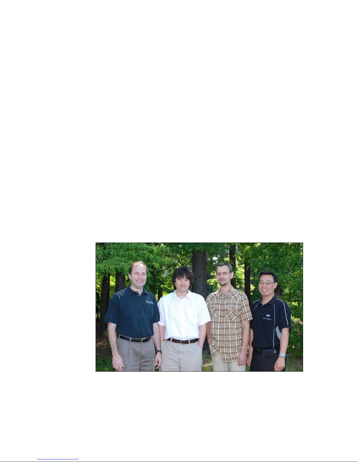
The team (left to right): David, Kevin, Jens, and Paul
Page 17

Preface xv
Thanks to the following people for their contributions to this project:
From the International Technical Support Organization:
Jeanne Alderson
Tam ik ia Ba rr ow
Emma Jacobs
Linda Robinson
Diane Sherman
Erica Wazewski
From IBM Marketing
Beth McElroy
Heather Richardson
Kevin Powell
Don Roy
Scott Tease
Bob Zuber
From IBM Development
Paul Anderson
Chia-Yu Chu
Richard French
Joe Jakubowski
Mark Kapoor
Don Keener
Dan Kelaher
Randy Kolvick
Josh Miller
Thanh Ngo
Chuck Stephan
From IBM Service and Support
Khalid Ansari
Brandon Church
Become a published author
Join us for a two- to six-week residency program! Help write a book dealing with
specific products or solutions, while getting hands-on experience with
leading-edge technologies. You will have the opportunity to team with IBM
technical professionals, Business Partners, and Clients.
Page 18

xvi Planning, Installing, and Managing the IBM System x3950 M2
Your efforts will help increase product acceptance and customer satisfaction. As
a bonus, you will develop a network of contacts in IBM development labs, and
increase your productivity and marketability.
Find out more about the residency program, browse the residency index, and
apply online at:
ibm.com/redbooks/residencies.html
Comments welcome
Your comments are important to us!
We want our books to be as helpful as possible. Send us your comments about
this book or other IBM Redbooks in one of the following ways:
Use the online Contact us review Redbooks form found at:
ibm.com/redbooks
Send your comments in an e-mail to:
redbooks@us.ibm.com
Mail your comments to:
IBM Corporation, International Technical Support Organization
Dept. HYTD Mail Station P099
2455 South Road
Poughkeepsie, NY 12601-5400
Page 19

© Copyright IBM Corp. 2008. All rights reserved. 1
Chapter 1. Technical overview
The IBM System x3950 M2 and IBM System x3850 M2 are the IBM System x
flagship systems. They are based on eX4 technology, which is the fourth
generation of IBM X-Architecture. This technology leverages the extensive
research and development by IBM in XA-64e chipset based on the scalable
Intel® Xeon MP system.
This chapters discusses the following topics:
1.1, “IBM eX4-based servers” on page 2
1.2, “Model numbers and scalable upgrade options” on page 9
1.3, “Multinode capabilities” on page 14
1.4, “x3950 M2 Windows Datacenter models” on page 15
1.5, “Integrated virtualization: VMware ESXi” on page 19
1.6, “IBM fourth generation XA-64e chipset” on page 27
1.7, “Processors” on page 33
1.8, “Memory subsystem” on page 39
1.9, “SAS controller and ports” on page 42
1.10, “PCI Express subsystem” on page 43
1.11, “Networking” on page 44
1.12, “Systems management features” on page 47
1.13, “Trusted Platform Module and where used” on page 51
1
Page 20
2 Planning, Installing, and Managing the IBM System x3950 M2
1.1 IBM eX4-based servers
IBM eX4 technology offers a balanced system design with unique scalability,
reliability, availability, and performance capabilities to take full advantage of Intel’s
latest multi-core processors. By connecting four servers together, the
single-system image can have up to 16 processor sockets (96 cores), up to 128
DIMM sockets and 1 TB of RAM, 28 PCI Express slots, and 34.1 GBps of
memory bandwidth for each 256 GB RAM server. This results in a high-capacity
system with significant processing and I/O performance, and greater power
efficiency.
The two servers based on IBM eX4 technology are:
IBM System x3850 M2
IBM System x3950 M2
Although they have the same technical specifications and features, the x3850 M2
cannot be used to form a multinode unless you upgrade it to an IBM System
x3950 M2 by adding the ScaleXpander Option Kit, as described in section 1.2,
“Model numbers and scalable upgrade options” on page 9.
1.1.1 Features of the x3950 M2 and x3850 M2 servers
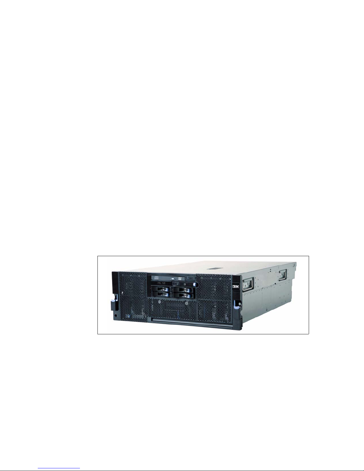
The x3950 M2 and x3850 M2 look very similar, as shown in Figure 1-1.
Figure 1-1 IBM System x3950 M2 and IBM System x3850 M2
Front and rear panels
The components and connectors on the front and rear of the system are shown
in Figure 1-2 on page 3 and Figure 1-3 on page 4.
Page 21
Chapter 1. Technical overview 3
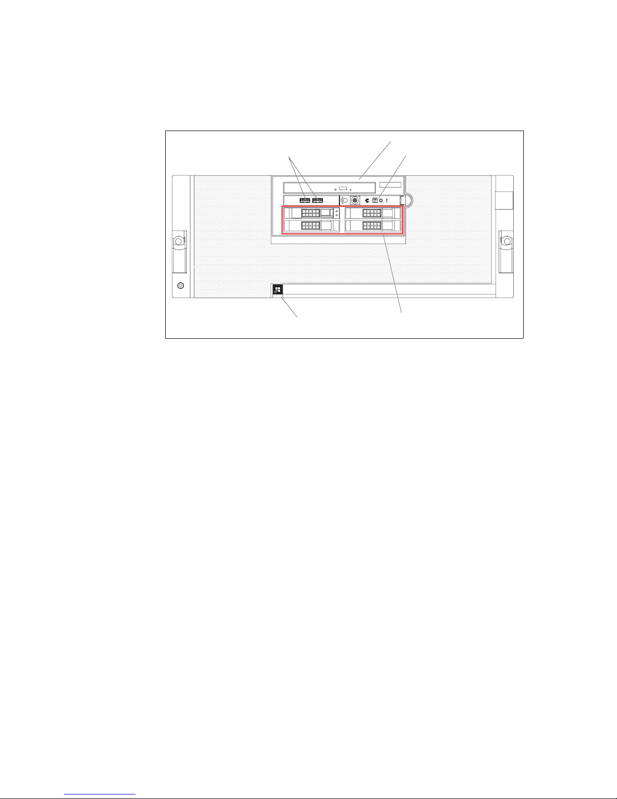
Figure 1-2 Front panel of x3850 M2 and x3950 M2
The front panel of the x3850 M2 and the x3950 M2, as shown in Figure 1-2,
provides easy access to a maximum of four hot-swap 2.5-inch SAS drives,
DVD-ROM, two USB 2.0 ports, an operator information panel with power on/off
button, and LEDs indicating information such as scalability, network activity, and
system errors and warnings.
The scalability LED on an x3950 M2 indicates whether the node (building block in
a scalable system) is participating in a multinode x3950 M2 complex. After each
node has successfully merged with the primary node in a partition, the scalability
LED is lit on all nodes in a partition of a multinode complex.
12
3
4
Operator information panel
USB connectors
DVD-R
O
M drive
Four hot-swap
disk drive bays
Scalability LED
Page 22
4 Planning, Installing, and Managing the IBM System x3950 M2
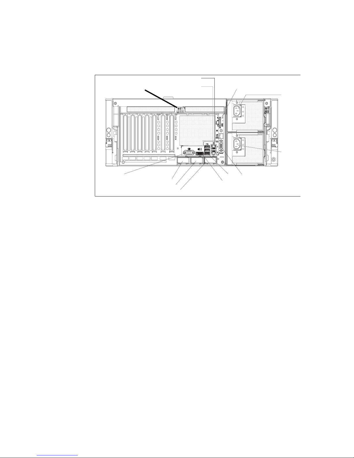
Figure 1-3 Rear panel of x3850 M2 and x3950 M2
The rear panel of the x3850 M2 and x3950 M2, as shown in Figure 1-3, has:
PCI Express (PCIe) slots 1 to 7 (from left to right on the panel)
System serial port
Three scalability SMP expansion ports used for multinode x3950 M2
complexes
External SAS port
Three USB 2.0 ports
Integrated dual-port Broadcom Gigabit Ethernet RJ45 ports
Remote Supervisor Adapter II panel, which contains the servers video
connector port, 10/100 Mbps RJ45 out-of-band remote management port
(there is also a mini-USB port and a power adapter socket that is not used for
the x3850 M2/x3950 M2)
Two hot-swap redundant power supplies
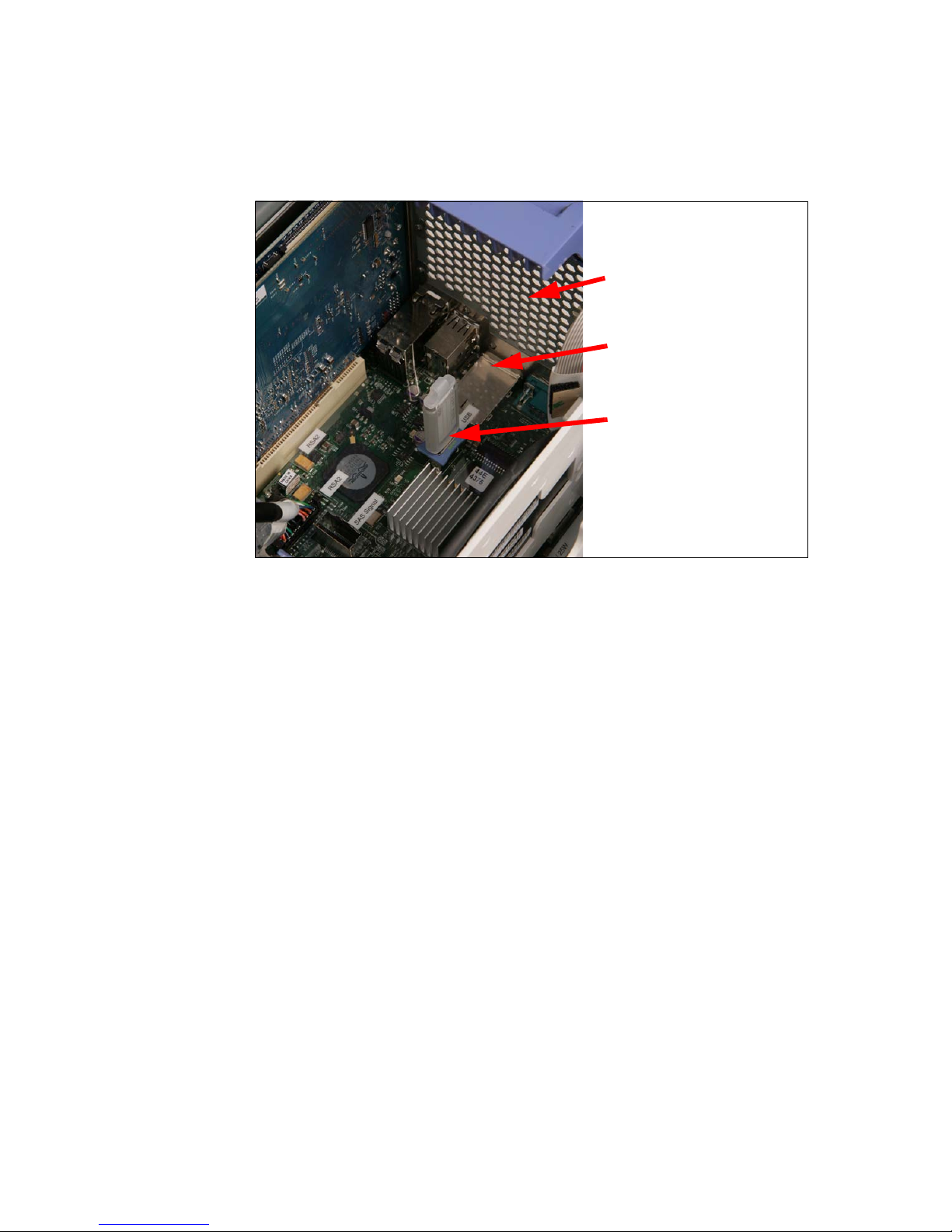
Hypervisor models of the x3850 M2
Inside the server is an additional USB socket used exclusively for the embedded
virtualization feature. This device, shown in Figure 1-4 on page 5, is standard on
hypervisor models of the x3850 M2.
Gigabit Ethernet 2
Gigabit Ethernet 1
SMP Expansion Port 1
SMP Expansion Port 2
SMP Expansion Port 3
USB
SAS
System serial
Powe r
supply 1
Powe r
supply 2
Remote Supervisor Adapter II
Video connector
Power-on, Locator and
System Error LEDs
Page 23
Chapter 1. Technical overview 5
Figure 1-4 On the hypervisor models of x3850 M2, a USB flash drive is pre-installed in
the internal USB socket and contains VMware ESXi 3.5 pre-loaded
Standard features for both systems
The x3950 M2 and x3850 M2 have the following standard features. We discuss
these in greater detail in sections later in this chapter.
Processors
Processor features include:
One 4U Rack-optimized sever with one of the following Intel processors:
– Xeon 7200 series (Tigerton) dual-core processors
– Xeon 7300 series (Tigerton) quad-core processors
– Xeon 7400 series (Dunnington) quad-core processors
– Xeon 7400 series (Dunnington) 6-core processors
Two processors standard, with support for up to four processors
One IBM eX4 “Hurricane 4” chipset with four 1066 MHz front-side buses
Support for Intel Virtualization Technology (Intel VT), Intel 64 technology
(EM64T), and Execute Disable Bit feature
Rear Air Ventilation Panel
as view from inside the
server
External SAS connector
as viewed from inside the
server
IBM 4 GB USB Flash Disk
pre-loaded with integrated
virtualization hypervisor
Page 24

6 Planning, Installing, and Managing the IBM System x3950 M2
Memory subsystem
Memory subsystem features include:
4 GB or 8 GB memory standard expandable to 256 GB
Support for 1, 2, 4, and 8 GB DDR2 registered DIMMs
Maximum of 32 DIMM slots by installing four memory card (each card has
eight DIMMs sockets)
Active Memory™ with Memory ProteXion, hot-swap memory with memory
mirroring, hot-add memory with supported operating systems, and Chipkill™.
I/O slots and integrated NICs
I/O subsystem features include:
Seven 64-bit PCIe x8 full height (half-length) slots; two of these seven slots
are hot-swap
Integrated dual-port Broadcom NeXtreme II 5709C PCI Express Gigabit
Ethernet controller with Jumbo Frame support
SAS RAID controller and HDD slots
Disk subsystem features include:
Integrated LSI 1078 SAS controller with support for RAID-0 and RAID-1
External JBOD SAS storage through external SAS x4 port (if IBM
ServeRAID™ MR10k SAS/SATA Controller is installed)
The SAS SFF-8088 connector is located above SMP Expansion Port 2 in
Figure 1-3 on page 4.
Up to four hot-swap 2.5-inch SAS hard drives (up to a maximum of 584 GB of
internal storage)
Systems management and security
Management and security features include:
Onboard BMC shares integrated Broadcom Gigabit Ethernet 1 interface
Remote Supervisor Adapter II with dedicated 10/100 Mbps Ethernet
management interface
The RSA Adapter II’s 10/100 Mbps Ethernet port is located above the video
connector in Figure 1-3 on page 4.
Operator information panel (see Figure 1-2 on page 3), which provides light
path diagnostics information
Note: TCP Offload Engine (TOE) support is planned.
Page 25

Chapter 1. Technical overview 7
Windows Hardware Error Architecture (WHEA) support in the BIOS
Trusted Platform Module support. The module is a highly secure start-up
process from power-on through to the startup of the operating system boot
loader. Advanced Configuration and Power Interface (ACPI) support is
provided to allow ACPI-enabled operating systems to access the security
features of this module.
System ports and media access
Ports and media access features include:
Six USB 2.0 ports, two on the front panel, three on the rear panel, and one
internal for USB Flash Disk
The Hypervisor model of x3850 M2 includes an integrated hypervisor for
virtualization on a 4 GB USB Flash Disk with VMware ESXi pre-loaded. See
Figure 1-4 on page 5.
An ATI™ Radeon™ ES1000™ SVGA video controller (DB-15 video
connector on RSA II card as shown in Figure 1-3 on page 4) on the Remote
Supervisor Adapter II
Optical drive:
– On machine type 7141: One standard 24x/8x IDE CD-RW/DVD-ROM
combo drive
– One machine type 7233: SATA CD-RW/DVD-ROM combo drive
USB keyboard and mouse
System serial port
Three SMP expansion ports for use in scalable multinode complex.
Power
Two hot-swap redundant 1440 W power supplies are standard. At 220 V, one
power supply is redundant. At 110 V, the power supplies are non-redundant.
1.1.2 x3950 M2: scalable hardware components
The x3950 M2 includes the following additional scalable hardware components
as standard compared to the x3850 M2. The additional components enable the
x3950 M2 to scale up to a multinode complex comprising of up to a maximum
four x3950 M2s.
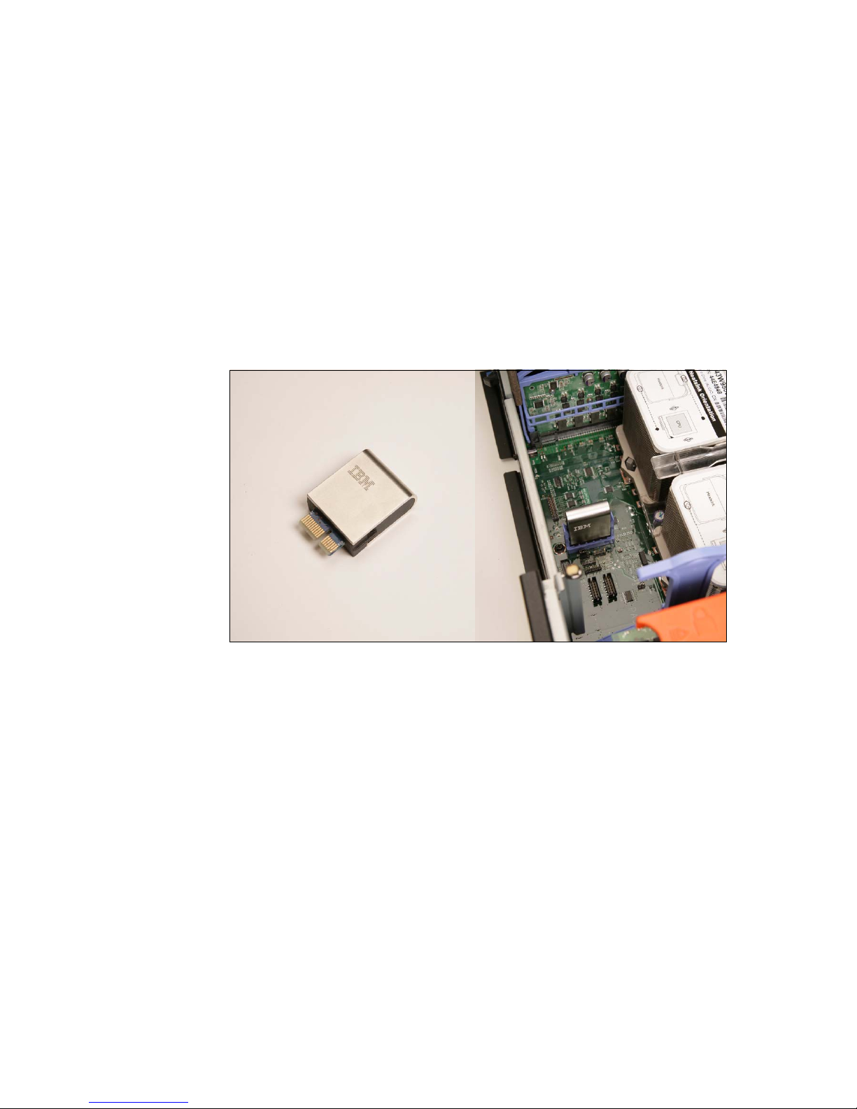
ScaleXpander chip (see Figure 1-5 on page 8)
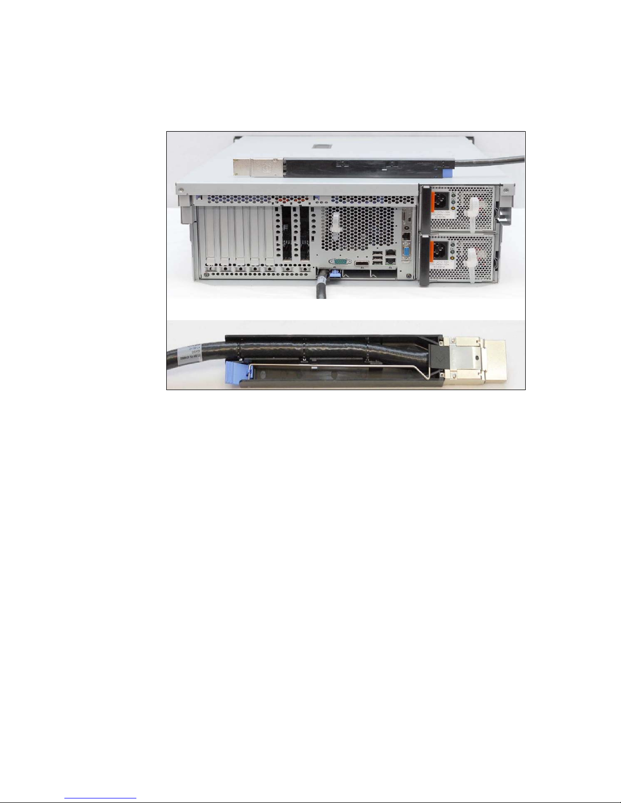
One 3.08 m scalability cable (see Figure 1-6 on page 9)
Page 26
8 Planning, Installing, and Managing the IBM System x3950 M2
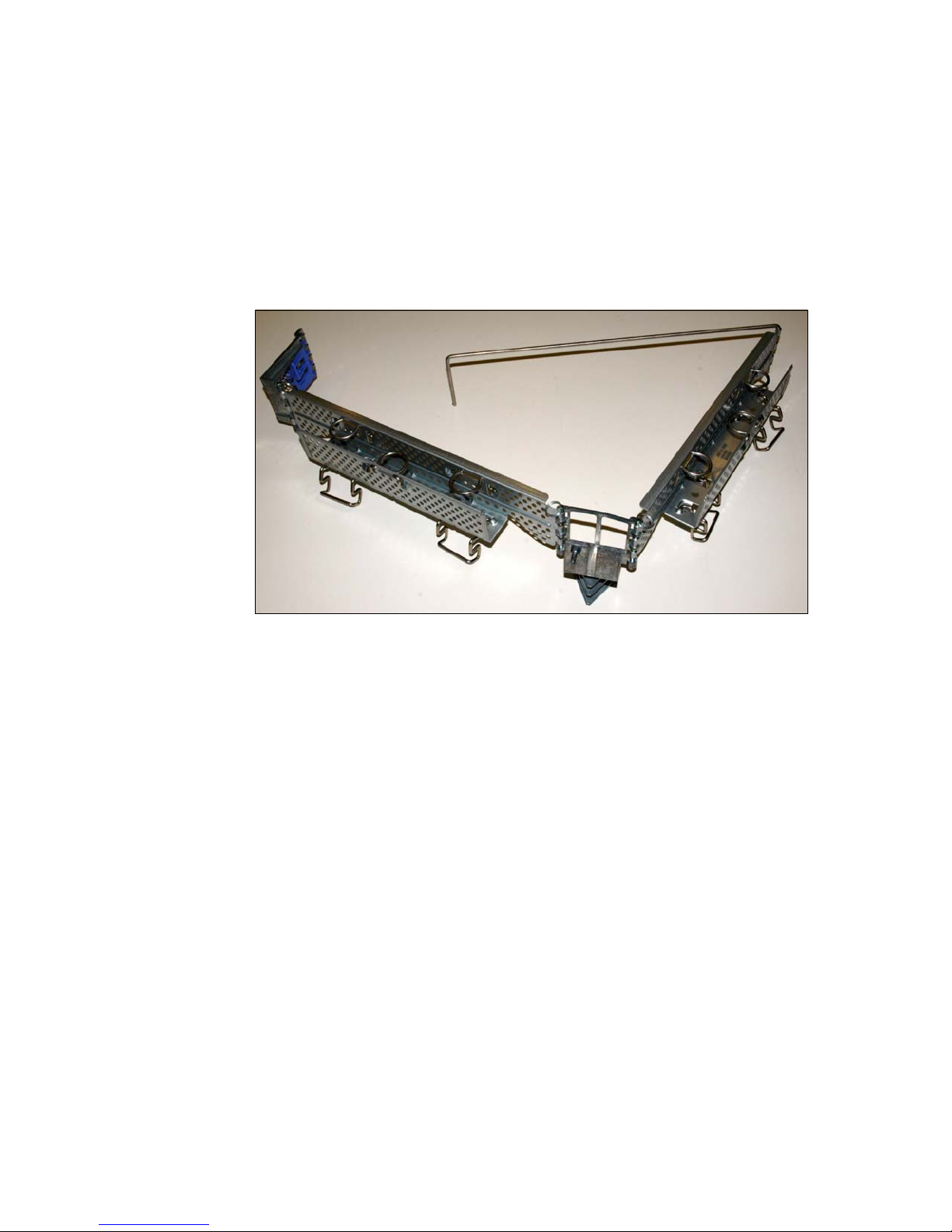
Larger cable management arm to accommodate use of scalability cables
connecting to SMP expansion ports (see Figure 1-7 on page 12 and
Figure 1-8 on page 13)
All necessary hardware components are provided for forming a three-node
x3950 M2 complex with the order of three x3950 M2 servers. However, to form a
four-node x3950 M2 complex, you must have four x3950 M2
and a Scalability
Upgrade Option 2, which contains one 3.08m and one 3.26m Scalability cable
(see Table 4-1 on page 202 for details of part numbers). Refer to Chapter 4,
“Multinode hardware configurations” on page 195 for more details about scaling
the x3950 M2 to complexes of two, three, and four nodes.
Figure 1-5 ScaleXpander chip (left); ScaleXpander chip installed on processor board
near the front panel of the x3950 M2 (right)
Page 27
Chapter 1. Technical overview 9
Figure 1-6 Scalability cable (top); cable installed in SMP Expansion Port 1 (bottom)
1.2 Model numbers and scalable upgrade options
As discussed previously, the x3850 M2 and x3950 M2 servers are based on
IBM eX4 technology. This section lists the available models for each server and
where to find more information about models available in your country.
The tables in this section use the following nomenclature:
n Indicates variations between server models relating to the processor
type and the number of memory cards and memory DIMMs installed.
c Indicates the country in which the model is available: U is for
countries in North America and South America. G is for EMEA (for
example, 1RG). For Asia-Pacific countries, the letter varies from
country to country.
Page 28

10 Planning, Installing, and Managing the IBM System x3950 M2
1.2.1 Finding country-specific model information
For the specific models available in your country, consult one of the following
sources of information:
Announcement letters; search for the machine type (such as 7141):
http://www.ibm.com/common/ssi/
Configuration and Options Guide (COG) for System x:
http://www.ibm.com/support/docview.wss?uid=psg1SCOD-3ZVQ5W
Direct link to COG page for the System x3850/3950 M2 servers:
http://www.ibm.com/systems/xbc/cog/x3850m2/x3850m2aag.html
IBM BladeCenter and System x Reference Sheets (xREF):
http://www.redbooks.ibm.com/xref
1.2.2 x3850 M2 model information
The model numbers of the x3850 M2 are listed in Table 1-1.
Table 1-1 Models of x3850 M2
Models Description
7141-nRc Standard models of x3850 M2 with dual-core or quad-core Xeon
7200 and Xeon 7300 (Tigerton) processors
7141-3Hc Integrated hypervisor models of x3850 M2 with Xeon E7330
(Tigerton) processors. See 1.5, “Integrated virtualization: VMware
ESXi” on page 19.
7233-nRc Standard models of x3850 M2 with quad-core and six-core Xeon
7400 (Dunnington) processors
7233-4Hc Integrated hypervisor models of x3850 M2 with quad-core Xeon
E7440 (Dunnington) processors. See 1.5, “Integrated virtualization:
VMware ESXi” on page 19.
Page 29

Chapter 1. Technical overview 11
1.2.3 x3950 M2 model information
The model numbers of the x3950 M2 are listed in Table 1-2.
Table 1-2 Models of x3950 M2
1.2.4 Scalable upgrade option for x3850 M2
Unlike the x3850 server (based on X3 technology), the x3850 M2 can be
converted to an x3950 M2 through the use of the IBM ScaleXpander Option Kit,
part number 44E4249. After this kit is installed, the x3850 M2 functionally
becomes an x3950 M2, and is therefore able to form part of a multinode complex
comprising of up to four x3950 M2s.
The IBM ScaleXpander Option Kit contains the following items:
Scalability cable 3.08m (See Figure 1-6 on page 9.)
Larger cable management arm, which replaces the existing arm to allow the
easy installation of the scalability cables. See Figure 1-7 on page 12 and
Figure 1-8 on page 13.
Models Description
7141-nSc Standard models of the x3950 M2 with dual-core or quad-core Xeon
7200 or Xeon 7300 (Tigerton) processors
7233-nSc Standard Models of x3950 M2 with quad-core and six-core Xeon
7400 (Dunnington) processors
a
a. Dunnington quad-core and six-core processors include L2 and L3 shared cache
unlike Tigerton processors with only L2 shared cache. See 1.7, “Processors” on
page 33 for more details.
7141-nAc Datacenter Unlimited Virtualization with High Availability models
certified for 32-bit Windows 2003 Datacenter Edition. See 1.4.2, “IBM
Datacenter Unlimited Virtualization with High Availability” on page 16.
7141-nBc Datacenter Unlimited Virtualization with High Availability models
certified for 64-bit Windows 2003 Datacenter Edition. See 1.4.2, “IBM
Datacenter Unlimited Virtualization with High Availability” on page 16.
7141-nDc Datacenter Unlimited Virtualization models certified for 32-bit
Windows 2003 Datacenter Edition. See 1.4.1, “IBM Datacenter
Unlimited Virtualization offering” on page 16.
7141-nEc Datacenter Unlimited Virtualization models certified for 64-bit
Windows 2003 Datacenter Edition. See 1.4.1, “IBM Datacenter
Unlimited Virtualization offering” on page 16.
Page 30
12 Planning, Installing, and Managing the IBM System x3950 M2
ScaleXpander chip required to convert the x3850 M2 to an x3950 M2. See
Figure 1-5 on page 8.
x3950 M2 bezel, which replaces the existing bezel and shows the x3850 M2
has the kit installed and is now functionally equal to an x3950 M2. See
Figure 1-9 on page 13.
Figure 1-7 x3950 M2 enterprise cable management arm
Page 31

Chapter 1. Technical overview 13
Figure 1-8 x3950 M2 cable management arm mounted on server rails
Figure 1-9 x3950 M2 bezel
Scalability cable brackets to guide the scalability
cables from the scalability expansion ports on one
node to another node
Route power, Ethernet, fibre
cables, video, mouse and
keyboard through here
Scalability expansion ports 1,
2, and 3 from left to right
Page 32

14 Planning, Installing, and Managing the IBM System x3950 M2
1.3 Multinode capabilities
The x3950 M2 is the base building block, or node, for a scalable system. At their
most basic, these nodes are comprised of four-way SMP-capable systems with
processors, memory, and I/O devices. The x3950 M2 is the building block that
allows supported 8-way, 12-way, and 16-way configurations by adding more
x3950 M2s as required.
Unlike with the System x3950 and xSeries® 460, the x3950 M2 does not require
a special modular expansion enclosure. The multinode configuration is simply
formed by using another x3950 M2 or an x3850 M2 that has the ScaleXpander
Option Kit installed as described previously in 1.2.4, “Scalable upgrade option for
x3850 M2” on page 11
Multinode configurations
The x3950 M2 can form a multinode configuration by adding one or more
x3950 M2 servers. A number of configurations are possible as shown in
Figure 1-10.
Figure 1-10 Possible multinode configurations
Note: When we refer to an x3950 M2, we mean either an x3950 M2 or an
x3850 M2 that has the ScaleXpander Option Kit installed.
Four nodes
8-way or 16-way
(Each node is
2-way or 4-way)
Up to 1 TB RAM
x3950 M2
x3950 M2
x3950 M2
x3950 M2
One node
2-way or 4-way
Up to 256 GB RAM
x3950 M2*
Two nodes
4-way or 8-way
(Each node is
2-way or 4-way)
Up to 512 GB RAM
x3950 M2
x3950 M2
Three nodes
6-way or 12-way
(Each node is
2-way or 4-way)
Up to 768 GB RAM
x3950 M2
x3950 M2
x3950 M2
Each node can be either an x3950 M2 or an x3850 M2
with the ScaleXpander Option Kit installed. All CPUs in
every node must be identical.
*
Page 33

Chapter 1. Technical overview 15
The possible configurations are:
A one-node system is a one x3950 M2 server or one x3850 M2 server, with
one, two, three, or four processors and up to 256 GB of RAM.
A two-node complex is comprised of two x3950 M2 servers, with up to eight
processors, and up to 512 GB RAM installed.
A three-node complex is comprised of three x3950 M2 servers, up to 12
processors, and up to 768 GB RAM installed.
A four-node complex is comprised of four x3950 M2 servers, up to 16
processors, and up to 1 TB RAM installed.
Partitioning
Partitioning is the concept of logically splitting a multinode complex into separate
systems. You can then install an operating system on a partition and have it run
independently from all other partitions. The advantage of partitioning is that you
can create and delete partitions without having to recable the complex. The only
requirement is that partitions be formed on node boundaries.
The interface where you set up and maintain partitions is an extension of the
Remote Supervisor Adapter II Web interface. It is used to create, delete, control,
and view scalable partitions.
Multinode complexes support partitioning on node boundaries. This means, for
example, you can logically partition your 2-node 8-way system as two 4-way
systems, while still leaving the complex cabled as 2 nodes. This increases
flexibility. You can reconfigure the complex by using the Web interface without
changing the systems or cabling.
For more information about multinode complexes and partitioning, see
Chapter 4, “Multinode hardware configurations” on page 195.
1.4 x3950 M2 Windows Datacenter models
IBM offers Windows 2003 Datacenter Edition as part of the following two IBM
offerings, which are described in this section:
IBM Datacenter Unlimited Virtualization
IBM Datacenter Unlimited Virtualization with High Availability
Note: At the time of writing, only Windows 2003 Enterprise and Datacenter
64-bit editions, RHEL 5 64-bit, and SLES 10 64-bit support this amount of
memory. See 2.6, “Operating system scalability” on page 66 for details.
Page 34

16 Planning, Installing, and Managing the IBM System x3950 M2
1.4.1 IBM Datacenter Unlimited Virtualization offering
The IBM Datacenter Unlimited Virtualization offering is ideal for customers who
already have a well-managed IT infrastructure and want only a Windows
operating system that scales from 4-way to 32-way and offers maximum
performance and scalability in a nonclustered environment.
IBM Datacenter Unlimited Virtualization solution is tested and certified on
specific System x servers and with standard ServerProven® options:
Datacenter-specific, certified configurations are no longer required
Supported on all ServerProven configurations for designated System x
Datacenter servers
Installation can be performed by IBM, the Business Partner, or the customer.
Optional System x Lab Services onsite and IBM Global Services - Remote
Support Services can be provided.
Table 1-2 on page 11 shows the system models for both 32-bit and 64-bit
versions of the operating system.
With the IBM Datacenter Unlimited Virtualization option, the x3950 M2 models
come with two processors, 8 GB of memory (eight 1 GB DIMMs), four memory
cards, and no disks. The system is shipped with the Datacenter installation CD,
OS documentation, recovery CD, and a 4-socket Certificate of Authenticity (COA)
to license the system. Windows Server® 2003 R2 Datacenter Edition is not
preloaded. This offering is available in both English and Japanese languages.
1.4.2 IBM Datacenter Unlimited Virtualization with High Availability
The IBM Datacenter Unlimited Virtualization with High Availability (UVHA)
Program offering delivers a fully certified solution on 4-way through 32-way
server configurations that support up to 8-node Microsoft cluster certified
solutions for a tightly controlled, end-to-end supported environment for maximum
availability.
This end-to-end offering provides a fully configured and certified solution for
customers who want to maintain a tightly controlled environment for maximum
Note: IBM no longer offers a Software Update Subscription for this offering.
Customers should purchase a Microsoft Software Assurance contract for
operating system maintenance and upgrades. For information see:
http://www.microsoft.com/licensing/sa
Page 35

Chapter 1. Technical overview 17
availability. To maintain this high availability, the solution must be maintained as a
certified configuration.
IBM Datacenter UVHA solution offerings are tested and certified on specific
System x servers and with standard ServerProven options, storage systems, and
applications. All components must be both ServerProven and Microsoft
cluster-logo certified.
The operating system is not preloaded. Installation must be performed by IBM
System x Lab Services or IBM Partners certified under the EXAct program.
Standard IBM Stage 2 manufacturing integration services can be used. IBM
Global Services - Remote Support Services are mandatory.
Table 1-2 on page 11 shows the models for both 32-bit and 64-bit versions of the
operating system.
With this option, the x3950 M2 models come with two processors, 8 GB memory
(eight 1 GB DIMMs), four memory cards, and no disks. Unlike previous
high-availability offerings, Windows Server 2003 R2 Datacenter Edition is not
preloaded. Also shipped with the system are a recovery CD, OS documentation,
and a 4-socket Certificate of Authenticity (COA) to license the system. This
offering is available in both English and Japanese languages.
1.4.3 Upgrading to Datacenter Edition
If you are using another Windows operating system on your x3950 M2, such as
Windows Server 2003 Enterprise Edition, and want to upgrade to Datacenter
Edition, you can order the appropriate upgrade as described in this section.
IBM Datacenter preload upgrades can be ordered only after receiving approval
from the IBM world-wide System x marketing team. IBM Sales Representatives
should notify their geography Marketing Product Manager and Sales Managers
of these opportunities, and the Product and Sales Managers should, in turn,
notify the World Wide Marketing Product Manager of the sales opportunity.
Business Partners should notify their IBM Sales Representative, who should
engage with geography Product Marketing and Sales Managers.
IBM validates the customer's current x3950 M2 hardware configuration as a
certified Datacenter configuration. Orders are allowed only after a Solutions
Note: IBM no longer offers a Software Update Subscription for this offering.
Customers should purchase a Microsoft Software Assurance contract for
operating system maintenance and upgrades. For information see:
http://www.microsoft.com/licensing/sa
Page 36

18 Planning, Installing, and Managing the IBM System x3950 M2
Assurance Review is completed. For the IBM Datacenter Unlimited Virtualization
with High Availability offering, the appropriate service and support contracts must
also be in place.
Upgrading to IBM Datacenter Unlimited Virtualization
To upgrade to the IBM Datacenter Unlimited Virtualization offering, order one or
more of the part numbers listed in Table 1-3. You must have one 4-CPU license
for each x3950 M2 in your configuration. Licenses are cumulative.
Table 1-3 Upgrade options for the IBM Datacenter Unlimited Virtualization offering
Upgrading to IBM Datacenter Unlimited Virtualization with
High Availability
To upgrade to the IBM Datacenter Unlimited Virtualization with High Availability
(UVHA) offering, order one or more of the part numbers listed in Table 1-4. You
must have one 4-CPU license for each x3950 M2 in your configuration. Licenses
are cumulative.
Table 1-4 Upgrade options for IBM Datacenter UVHA
Upgrade kits Order number
Windows Server 2003 Datacenter Edition R2, 32-bit, 1-4 CPUs 4818-NCU
Windows Server 2003 Datacenter Edition R2 x64, 1-4 CPUs 4818-PCU
Windows Server 2003 Datacenter Edition R2, 32-bit, 1-4 CPUs
(Japanese)
4818-NCJ
Windows Server 2003 Datacenter Edition R2 x64, 1-4 CPUs
(Japanese)
4818-PCJ
Note: These upgrade order numbers can only be ordered from the IBM World
Wide System x Brand and might not appear in IBM standard configuration
tools.
Upgrade kits Order number
Windows Server 2003 Datacenter Edition R2, 32-bit, 1-4 CPUs 4816-NCU
Windows Server 2003 Datacenter Edition R2 x64, 1-4 CPUs 4816-PCU
Page 37

Chapter 1. Technical overview 19
1.4.4 Datacenter multinode configurations
Configurations greater than 4-way on the x3950 M2 are comprised of an
x3950 M2 primary node with a number of x3950 M2 systems, up to a maximum
of four nodes to make a 16-way Datacenter system. Forming these scalable
systems requires additional scalability cables, as explained in 4.4, “Prerequisites
to create a multinode complex” on page 201.
1.4.5 Datacenter cluster configurations
Microsoft Cluster Server (MSCS) is supported only under the UVHA offering.
Check for updates to the Microsoft Hardware Compatibility List (HCL) at:
http://www.microsoft.com/whdc/hcl/default.mspx
1.5 Integrated virtualization: VMware ESXi
VMware ESXi is the next-generation hypervisor that is integrated into IBM
servers such as the x3850 M2. It provides a cost-effective, high-capacity virtual
machine platform with advanced resource management capabilities. This
innovative architecture operates independently from any general-purpose
operating system, offering improved security, increased reliability, and simplified
management. The compact architecture is designed for integration directly into
virtualization-optimized server hardware like the IBM x3850 M2, enabling rapid
installation, configuration, and deployment.
Windows Server 2003 Datacenter Edition R2, 32-bit, 1-4 CPUs
(Japanese)
4816-NCJ
Windows Server 2003 Datacenter Edition R2 x64, 1-4 CPUs
(Japanese)
4816-PCJ
Note: These upgrade order numbers can only be ordered from the IBM World
Wide System x Brand and might not appear in IBM standard configuration
tools.
Upgrade kits Order number
Page 38

20 Planning, Installing, and Managing the IBM System x3950 M2
1.5.1 Key features of VMware ESXi
As discussed in the white paper The Architecture of VMware ESX Server 3i1,
VMware ESXi has equivalent functions to ESX Server 3.5. However, the ESXi
hypervisor footprint is less than 32 MB of memory because the Linux-based
service console has been removed. The function of the service console is
replaced by new remote command line interfaces in conjunction with adherence
to system management standards.
Like the ESX Server, VMware ESXi supports the entire VMware Infrastructure 3
suite of products, including VMFS, Virtual SMP®, VirtualCenter, VMotion®,
VMware Distributed Resource Scheduler, VMware High Availability, VMware
Update Manager, and VMware Consolidated Backup.
The VMware ESXi architecture comprises the underlying operating system,
called VMkernel, and processes that run on it. VMkernel provides the means for
running all processes on the system, including management applications and
agents as well as virtual machines. VMkernel also manages all hardware devices
on the server, and manages resources for the applications.
The main processes that run on top of VMkernel are:
Direct Console User Interface (DCUI), which is the low-level configuration and
management interface, accessible through the console of the server, and
used primarily for initial basic configuration.
The virtual machine monitor, which is the process that provides the execution
environment for a virtual machine, as well as a helper process known as
VMX. Each running virtual machine has its own VMM and VMX process.
Various agents are used to enable high-level VMware Infrastructure
management from remote applications.
The Common Information Model (CIM) system, which is the interface that
enables hardware-level management from remote applications through a set
of standard APIs.
Figure 1-11 on page 21 shows a components diagram of the overall ESXi 3.5
architecture.
For detailed examination of each of these components, refer to the previously
mentioned white paper, The Architecture of VMware ESX Server 3i, at:
http://www.vmware.com/files/pdf/ESXServer3i_architecture.pdf
1
Available from http://www.vmware.com/files/pdf/ESXServer3i_architecture.pdf. This section
contains material from VMware. Used with permission.
Page 39

Chapter 1. Technical overview 21
Figure 1-11 The architecture of VMware ESXi eliminates the need for a service console
1.5.2 VMware ESXi on x3850 M2
Although VMware ESXi can be booted from flash memory or installed on a hard
disk, ESXi is currently available from IBM only on specific systems, including
specific models of the x3850 M2. These models have an integrated bootable
USB flash drive that is securely installed to an internal USB port.
With an IBM eX4 server running VMware ESXi (or VMware ESX), applications
and services can be deployed in highly reliable and secure virtual machines.
Virtual machines can be provisioned, consolidated, and managed centrally
without having to install an operating system, thus simplifying the IT
infrastructure and driving down total cost of ownership for businesses with
constrained IT budgets and resources.
One important recommended consideration when selecting a server to run
VMware ESX is to ensure you have sufficient headroom in capacity. The IBM
x3850 M2 is optimized for VMware ESXi because of its vertical scalability in the
key areas such as processor, memory, and I/O subsystems. VMware discusses
the benefits of CPU dense ESX server hosts by saying
2
:
The chance that the scheduler can find room for a particular workload without
much reshuffling of virtual machines will always be better when the scheduler
has more CPUs across which it can search for idle time. For this reason, it will
generally be better to purchase two four-way ESX Server licenses than to
purchase four two-way machines.
VM kernel
VMMOSVMMOSVMM
OS
Virtual Ethernet
adapter and switch
Network stack
Distributed
VM file system
Storage stack
Device drivers
Resource
scheduling
User world API
CIM broker
Third-party
CIM plug-ins
vpxa SNMP
hostd DCUI syslog VMX VMX VMX
2
See Tips and Techniques for Implementing Infrastructure Services on ESX Server, available at:
http://www.vmware.com/vmtn/resources/409. Reproduced by permission.
Page 40

22 Planning, Installing, and Managing the IBM System x3950 M2
Similarly, two eight-way servers will provide more scheduling flexibility than four
4-way servers. Refer to the white paper, Tips and Techniques for Implementing
Infrastructure Services on ESX Server available from:
http://www.vmware.com/vmtn/resources/409
Table 1-5 shows that scheduling opportunities scale exponentially rather than
linearly when more cores are available.
Table 1-5 Scheduling opportunities scale exponentially when there are more cores
1.5.3 Comparing ESXi to other VI3 editions
VMware ESXi is one of the new VMware VI Editions being offered from VMware
and provides the same functionality as ESX 3.5. VMware ESXi can be upgraded
to VI Foundation, Standard, and Enterprise Editions to provide additional
management features as detailed in Table 1-6.
Table 1-6 Feature comparison
ESX Host Server Number of Cores Scheduling
opportunities
(VM = 2 vCPUs)
4-way Dual Core 8 28
8-way Dual Core 16 120
8-way Quad Core 32 496
Feature VMware ESXi VI Foundation VI Standard VI Enterprise
VMFS Virtual SMP
Ye s Ye s Ye s Ye s
VC Agent - Central
management
No
Ye s Ye s Ye s
Update manager No
Ye s Ye s Ye s
Consolidated backup No
Ye s Ye s Ye s
High availability No No
Ye s Ye s
DRS - Resource management No No No
Ye s
DPM - Power management No No No
Ye s
VMotion - Live VM migration No No No
Ye s
Storage VMotion - Live VM disk
file migration
No No No
Ye s
Page 41

Chapter 1. Technical overview 23
VMware is available in several editions, including:
VMware Infrastructure Enterprise Edition
This edition contains the entire array of virtual infrastructure capabilities for
resource management, workload mobility, and high availability. It includes:
– VMware ESX Server
– VMware ESXi
– VMware Consolidated Backup
– VMware Update Manager
– VMware VMotion
– VMware Storage VMotion
– VMware DRS with Distributed Power Management (DPM)
– VMware HA
VMware Infrastructure Standard Edition
This edition is designed to bring higher levels of resiliency to IT environments
at greater value. It includes:
– VMware HA
– VMware ESX Server
– VMware ESXi
– VMware Consolidated Backup
– VMware Update Manager
VMware Infrastructure Foundation Edition
Unlike the previous VMware Infrastructure 3 Starter Edition, VMware
Infrastructure Foundation Edition has no restrictions on shared storage
connectivity, memory utilization, or number of CPUs of the physical server.
It includes:
– VMware ESX Server
– VMware ESXi
– VMware Consolidated Backup
– VMware Update Manager
New features such as VMware High Availability (VMware HA), Distributed
Resource Scheduler (DRS), and Consolidated Backup provide higher
availability, guaranteed service level agreements, and quicker recovery from
failures than was previously possible, and comes close to the availability you
get from more expensive and complicated alternatives such as physically
clustered servers.
Page 42

24 Planning, Installing, and Managing the IBM System x3950 M2
VMware Infrastructure ESXi Edition
This edition has no restrictions on shared storage connectivity, memory
utilization, or number of CPUs of the physical server. However, if you
purchase IBM x3850 M2 with VMware ESXi integrated hypervisor and
subsequently require additional functionality, you can upgrade ESXi to the VI
Enterprise, Standard, or Foundation Editions. See “License upgrades from
ESXi to VI3 Editions” on page 25 for details about upgrade options.
The System x3850 M2 and x3950 M2 servers are designed for balanced system
performance, and are therefore uniquely positioned to take advantage of the
larger workloads now available to be virtualized.
Table 1-7 shows the limitations of each VMware distribution that is supported on
the x3850 M2 and x3950 M2 (single node).
Table 1-7 Features of the VMware ESX family
Note: For all VMware VI3 Infrastructure editions (Enterprise, Standard, and
Foundation), two Socket licenses must be purchased with a corresponding
subscription and support for the VI3 Edition purchased. The licenses are also
valid for use with ESXi Installable Edition. VMware ESXi is now available free
of cost, with no subscription required, however additional VI3 features are
licensed separately.
Feature ESX Server 3.0.2
update 1
VMware ESXi
VMware ESX V3.5
Maximum logical CPUs
a
a. Each core is equal to a logical CPU.
32 32 (64 logical CPUs are
supported experimentally
by VMware)
Maximum memory 64 GB 256 GB
Size of RAM per virtual
machine
16,384 MB 65,532 MB
Note: The values in the table are correct at the time of writing and may change
as testing completes. The values do not reflect the theoretical values but set
the upper limit of support for either distribution.
Page 43

Chapter 1. Technical overview 25
For more information about the configuration maximums of ESX Server, see:
ESX Server 3.0.2 configuration maximums:
http://www.vmware.com/pdf/vi3_301_201_config_max.pdf
VMware ESX V3.5 and VMware ESXi V3.5 configuration maximums:
http://www.vmware.com/pdf/vi3_35/esx_3/r35/vi3_35_25_config_max.pdf
1.5.4 VMware ESXi V3.5 licensing
As described in 1.2.2, “x3850 M2 model information” on page 10, specific
hypervisor models of the x3850 M2 includes VMware ESXi V3.5, the embedded
virtualization engine on an IBM customized USB Flash Disk. These models
include a license for VMware ESXi V3.5 for up to four processor sockets.
Subscriptions for updates
In addition, subscriptions for updates to VMware ESXi V3.5 are recommended,
but not mandatory, to be purchased for each ESXi V3.5 (four-socket) license
using product number 5773-VMW:
Subscription for two processor sockets: Feature code 0997
Subscription for four processor sockets: Feature code 0998
For more details, see the IBM Announcement Letter 208-071:
http://www.ibm.com/isource/cgi-bin/goto?it=usa_annred&on=208-071
License upgrades from ESXi to VI3 Editions
VMware ESXi can be upgrade to provide the additional features available in the
VMware Infrastructure Enterprise, Standard or Foundation Editions, with a
purchase of licenses from IBM as shown in Table 1-8 on page 26.
Note: VMware ESXi is available only in a dedicated model of the x3850 M2
(as described in 1.2.2, “x3850 M2 model information” on page 10) or in
configure-to-order (CTO) models pre-loaded as a Factory Install (product
number 5773-VMW).
Page 44

26 Planning, Installing, and Managing the IBM System x3950 M2
Table 1-8 VMware license, subscription, support options for ESX 3.5 and ESXi
For details of part numbers, refer to VMware Offerings in the IBM System x
Configuration and Options Guide:
http://www.ibm.com/systems/xbc/cog/vmwareesx.html
For example, to upgrade an ESXi 4-socket license for x3850 M2 hypervisor
model (with 4 x processor sockets populated), purchase the following items:
Two VMware ESX Server 3i to Enterprise Upgrade, 2-socket license only
Two Subscription Only VMware ESX Server 3i to Enterprise Upgrade,
2-socket, 3-year support
Two VMware Infrastructure 3, Enterprise, 2-socket, 3-year support
The exact description of the parts above might differ slightly from country to
country, or by the length (in years) of subscription and support. License
upgrades, subscription upgrades, and support must be purchased as a complete
set to upgrade ESXi Edition to Virtual Infrastructure Foundation, Standard, and
Enterprise Editions.
1.5.5 Support for applications running on VMware ESX and ESXi
Ensure that the applications you plan to use on the x3850 M2 and x3950 M2
running VMware ESX Server are supported by the application vendor:
Microsoft
See the following Microsoft support Web site for details about its support of
applications and operating systems running on ESX Server:
http://support.microsoft.com/kb/897615/
Description Quantity for
[x3850 M2 / x3950
M2] (single node)
with 2 sockets
Quantity for
[x3850 M2 / x3950
M2] (single node)
with 4 sockets
VMware ESX 3i to [Enterprise,
Standard, or Foundation] upgrade,
2-socket license only
12
Subscription only VMware ESX 3i to
[Enterprise, Standard, or Foundation]
upgrade, 2-socket,1 or 3 year support
12
Virtual Infrastructure 3, [Enterprise,
Standard, or Foundation], 2-socket, 1 or
3 year support
12
Page 45

Chapter 1. Technical overview 27
IBM software
If you are running IBM software such as WebSphere®, Lotus®, and Tivoli®
products on VMware ESX Server, you must have an IBM Remote Technical
Support ServicePac® or IBM VMware Support Line agreement through the
IBM Support Line or the IBM equivalent. You must have a current Software
Maintenance Agreement to receive support for the IBM software products in
this environment. Individual IBM software products can have a level of
customer support beyond that described in the product announcement. If
applicable, information about the added support will be included in the
specific product announcement letter.
VMware ESX software is designed to be transparent to the middleware and
applications that operate above the VMware guest operating system. If an
IBM software problem occurs only within a VMware ESX environment, it will
be considered a transparency problem and will be directed to VMware for
resolution. The IBM VMware Support Line is available to provide assistance
in working with the customer and the VMware Business Partner to resolve this
type of problem.
Customer implementations that are not covered by an IBM VMware Support
Line agreement are required to re-create the problem in a native environment
without VMware in order to use Software Maintenance support services for
the IBM software that is experiencing the problem.
1.6 IBM fourth generation XA-64e chipset
The x3850 M2 and x3950 M2 use the fourth generation of the IBM XA-64e or
eX4 chipset.
This chipset is designed for the Xeon MP processor family from Intel. The IBM
eX4 chipset provides enhanced functionality and capability with significant
improvements in scalability, decreased memory latency, increased memory
bandwidth and increased I/O bandwidth. The architecture consists of the
following components:
One to four Xeon dual-core, quad-core, or 6-core processors
Hurricane 4 Memory and I/O Controller (MIOC)
Eight high-speed memory buffers
Two PCI Express bridges
One Enterprise Southbridge Interface
Figure 1-12 on page 28 shows a block diagram of the x3850 M2 and x3950 M2.
Page 46

28 Planning, Installing, and Managing the IBM System x3950 M2
Figure 1-12 x3850 M2 and x3950 M2 system block diagram
Each memory port out of the memory controller has a peak read throughput of
4.26 GBps and a peak write throughput of 2.13 GBps. DIMMs are installed in
matched pairs, two-way interleaving, to ensure the memory port is fully utilized.
Peak throughput for each PC2-5300 DDR2 DIMM is 4.26 GBps.
There are eight memory ports; spreading the installed DIMMs across all ports
can improve performance. The eight independent memory ports provide
simultaneous access to memory. With four memory cards installed, and eight
DIMMs in each card, peak read memory bandwidth is 34.1 GBps and peak write
bandwidth is 17.1 GBps. The memory controller routes all traffic from the eight
memory ports, four microprocessor ports, and the three PCIe bridge ports.
The memory controller also has an embedded DRAM that, in the x3850 M2 and
x3950 M2, holds a snoop filter lookup table. This filter ensures that snoop
B = bytes
b = bits
Seven PCI Express x8 slots
(slots 6 & 7 are hot-swap)
IBM X4
Architecture
core chipset
6543
HDD backplane
Each FSB:
1066 MHz
8.53 GBps
8 ports, each:
R: 4.26 GBps
W: 2.13 GBps
HSS-IB 6 GBps
Serial
Scalability ports
10.24 GBps each
72
1
MR10k
External SAS port
LSI
1078
SAS
DVD drive
6x USB 2.0
PCI +
USB
PCI-E x4
2 GBps
South bridge
DDR2
Buffer
DDR2
Buffer
DDR2
Buffer
DDR2
Buffer
DDR2
Buffer
DDR2
Buffer
DDR2
Buffer
DDR2
Buffer
PCI-E bridge 1 PCI-E bridge 2
Memory
controller
("Hurricane 4")
CPU 2 CPU 3CPU 1 CPU 4
Gb Ethernet
BCM5709C
RSA2 +
Video
HSS-IB 6 GBps
Page 47

Chapter 1. Technical overview 29
requests for cache lines go to the appropriate microprocessor bus and not all four
of them, thereby improving performance.
The three scalability ports are each connected to the memory controller through
individual scalability links with a maximum theoretical bidirectional data rate of
10.24 GBps per port.
IBM eX4 has two PCIe bridges and each are connected to a HSS-IB port of the
memory controller with a maximum theoretical bidirectional data rate of 6 GBps.
As shown in Figure 1-12 on page 28, PCIe bridge 1 supplies four of the seven
PCI Express x8 slots on four independent PCI Express buses. PCIe bridge 2
supplies the other three PCI Express x8 slots plus the onboard SAS devices,
including the optional ServeRAID-MR10k and a 4x external onboard SAS port.
A separate Southbridge is connected to the Enterprise Southbridge Interface
(ESI) port of the memory controller through a PCIe x4 link with a maximum
theoretical bidirectional data rate of 2 GBps. The Southbridge supplies all the
other onboard PCI devices, such as the USB ports, onboard Ethernet and the
standard RSA II.
1.6.1 Hurricane 4
Hurricane 4 is the north bridge component of the IBM eX4 chipset designed for
latest Intel Core™ Architecture-based processors which feature a new
architecture for the processor front-side bus. Hurricane 4 supports the
processors in the Xeon 7000 family of processors, including those with code
names of
Tigerton and Dunnington.
Hurricane 4 is an enhanced memory controller with Level 4 (L4) scalability
cache. Hurricane 4 contains processor scalability support for up to 16 sockets
across four NUMA nodes. Hurricane 4 provides the following features:
Reduced local and remote latency compared to the X3 chipset in the x3950
Integrated memory controller, NUMA controller, two I/O channels and three
scalability ports
Local memory used for scalability L4 cache for a multinode environment
Connectivity to high speed memory hub module, two PCIe bridges, and a
Southbridge
Scalability to 16 socket SMP system providing industry leading performance
Support for four front-side buses, one for each of the four Intel Xeon® MP
processors
Page 48

30 Planning, Installing, and Managing the IBM System x3950 M2
1.6.2 XceL4v dynamic server cache
The XceL4v dynamic server cache is a technology developed as part of the IBM
XA-64e fourth-generation chipset. It is used in two ways:
As a single four-way server, the XceL4v and its embedded DRAM (eDRAM) is
used as a snoop filter to reduce traffic on the front-side bus. It stores a
directory of all processor cache lines to minimize snoop traffic on the four
front-side buses and minimize cache misses.
When the x3950 M2 is configured as a multinode server, this technology
dynamically allocates 256 MB of main memory in each node for use as an L4
cache directory and scalability directory. This means an eight-way
configuration has 512 MB of XceL4v cache.
Used in conjunction with the XceL4v Dynamic Server Cache is an embedded
DRAM (eDRAM), which in single-node configurations contains the snoop filter
lookup tables. In a multinode configuration, this eDRAM contains the L4 cache
directory and the scalability directory.
1.6.3 PCI Express I/O bridge chip
Two single-chip PCIe host bridges are designed to support PCIe adapters for
IBM x3850 M2 and x3950 M2 servers. The PCIe bridges each have one HSS-IB
port that provide connectivity to Hurricane 4 memory controller chip and also
another HSS-IB link between the PCIe bridges for redundancy in the event one of
the links from the Hurricane 4 chipset to the two PCIe bridges are not working.
The HSS-IB links are capable of up to 3.0 GBps bandwidth in each direction per
port or up to 6.0 GBps bidirectional bandwidth (see Figure 1-12 on page 28).
Each PCIe chip provides four separate PCIe x8 buses to support four PCIe x8
slots. PCIe Bridge 1 supports slots 1-4 of the PCIe x8 slots and PCIe Bridge 2
supports slots 5-7 of the PCIe x8 slots and a dedicated PCIe x8 slot for
ServeRAID MR10k SAS/SATA RAID controller.
1.6.4 High-speed memory buffer chips
The two high-speed memory buffer chips on each memory card are used to
extended memory capacity. They provide the necessary functions to connect up
to 32 8-byte ranks of DDR-II memory (see 1.6.5, “Ranks” on page 31 for an
explanation of ranks of memory). Each buffer supports multiple data flow modes
Note: The amount of memory that BIOS reports is minus the portion used for
the XceL4v cache.
Page 49

Chapter 1. Technical overview 31
that allow configurable combinations of controller data bus widths. These modes
allow its bandwidth and capacity to be optimized for many system configurations.
1.6.5 Ranks
A rank is a set of DRAM chips on a DIMM that provides eight bytes (64 bits) of
data.
Memory in servers is implemented in the form of DIMMs, which contain a number
of SDRAM (or just DRAM) chips.
The capacity of each DRAM is a number of
words where each word can be 4 bits
(x4), 8 bits (x8) and, starting to become prevalent, 16 bits in length (x16).
The word length is usually written as x4 for 4 bits, and so on. The number of
words in the DRAM is sometimes written on the label of the DIMM, such as a
DRAM chip on a DIMM.
DIMMs are typically configured as either single-rank or double-rank devices but
four-rank devices are becoming more prevalent.
The DRAM devices that make up a rank are often, but not always, mounted on
one side of the DIMM, so a single-rank DIMMs can also be referred to as a
single-sided DIMM. Likewise a double-ranked DIMM can be referred to as a
double-sided DIMM.
Refer to “Chapter 8, Memory subsystem” of the IBM Redbooks publication
Tuning IBM System x Servers for Performance, SG24-5287 for more details.
1.6.6 Comparing IBM eX4 to X3 technologies
This section discusses the improvements in the design of IBM eX4 technology as
compared to the design of previous X3 technology. A block diagram of the X3
technology is shown in Figure 1-13 on page 32.
Page 50

32 Planning, Installing, and Managing the IBM System x3950 M2
Figure 1-13 Block diagram of IBM X3 x3850/x366 and x3950/x460
IBM eX4 technology builds and improves upon its previous generation X3
technology. The key enhancements are:
Processor interface
– Quad 1066 MHz front-side bus (FSB), which has a total bandwidth of up to
34.1 GBps. In X3, the maximum bandwidth was 10.66 GBps.
– The front-side bus is increased to 1066 MHz from 667 MHz for 3.2x
bandwidth improvement.
– Snoop filter is for quad FSB coherency tracking compared to X3 with only
dual FSB coherency tracking.
Memory
– Increased (four-fold) memory capacity (2X from chipset, 2X from DRAM
technology) compared to X3.
66
Six PCI-X 2.0 slots:
64-bit 266 MHz
IBM XA-64e
core chipset
CPU 2 CPU 3
654
DDR2
SMI2
DDR2 SMI2
DDR2
SMI2
DDR2
SMI2
CPU 1 CPU 4
Memory
controller
("Hurricane")
3
21
HDD
backplane
Adaptec
SAS
Gigabit
Ethernet
ServeRAID
266 MHz266 MHz266
33
South
bridge
EIDE
RSA SL
Each:
667 MHz
5.33 GBps
667 MHz
5.33 GBps
6 GBps
667 MHz
5.33 GBps
Calgary
PCI-X bridgePCI-X bridge
USB 2.0
Video
6 GBps
6 GBps
Serial
K/M
Scalability ports
Each: 6.4 GBps
(x460 and
MXE-460 only)
Page 51

Chapter 1. Technical overview 33
– Eight memory channels are available in eX4, compared to four memory
channels in X3.
– Memory bandwidth improved 1.6x is eX4. The eX4 has 34.1 GBps read
and 17.1 GBps write aggregate peak memory bandwidth versus
21.33 GBps aggregate peak memory bandwidth in X3.
– Lower memory latency in the eX4 because the eX4 uses DDR2 533 MHz
memory compared to DDR2 333 MHz memory in X3.
Direct connect I/O
– Earlier X3 models used a PCI-X chipset instead of the PCI Express
chipset in eX4.
– The ServeRAID MR10K SAS/SATA RAID controller in the x3950 M2 no
longer shares bandwidth on a shared bus such as the ServeRAID 8i SAS
RAID controller in the x3950 did with devices like the Gigabit Ethernet
controllers in X3. With its own dedicated PCIe slot, the ServeRAID MR10k
has improved throughput and ability to support external SAS devices
through the integrated external SAS port.
– Dedicated Southbridge ESI port to support Southbridge devices such as
RSA II, dual Gigabit Ethernet controllers, IDE DVD-ROM, USB port, Serial
port and Video interface.
Scalability
– Almost twice the increase in scalability port bandwidth for improved
scaling. The eX4 has three scalability ports with increased bandwidth of
30.72 GBps compared to 19.2 GBps in X3.
1.7 Processors
As mentioned previously, the x3850 M2 and x3950 M2 models use one of the
following Intel Xeon Processor models:
Tigerton (code name) processors:
Xeon 7200 series dual-core processors
Xeon 7300 series quad-core processors
Dunnington (code name) processors:
Xeon 7400 series quad-core processors
Xeon 7400 series 6-core processors
Refer to 1.2, “Model numbers and scalable upgrade options” on page 9 for details
about the current models.
Page 52

34 Planning, Installing, and Managing the IBM System x3950 M2
All standard models of the x3850 M2 and x3950 M2 have two processors
installed. One, two, three, or four processors are supported. Installed processors
must be identical in model, speed, and cache size.
As described in 1.3, “Multinode capabilities” on page 14, you can also connect
multiple x3950 M2s to form larger single-image configurations.
The processors are accessible from the top of the server after opening the media
hood. The media hood is hinged at the middle of the system and contains the
SAS drives, optical media, USB ports and light path diagnostic panel.
Figure 1-14 shows the media hood half-way open.
Figure 1-14 The x3950 M2 with the media hood partially open
The processors are each packaged in the 604-pin Flip Chip Micro Pin Grid Array
(FC-mPGA) package. It is inserted into surface-mount mPGA604 socket. The
processors use a large heat-sink to meet thermal specifications.
Tip: For the purposes of VMware VMotion, the Dunnington processors are
compatible with the Tigerton processors.
Page 53

Chapter 1. Technical overview 35
The Xeon E7210 and E7300 Tigerton
processors have two levels of cache on the
processor die:
Each pair of cores in the processor has either 2, 3, or 4 MB shared L2 cache
for a total of 4, 6, or 8 MB of L2 cache. The L2 cache implements the
Advanced Transfer Cache technology.
L1 execution trace cache in each core is used to store micro-operations and
decoded executable machine instructions. It serves those to the processor at
rated speed. This additional level of cache saves decode-time on cache-hits.
The Tigerton processors do not have L3 cache.
Figure 1-15 compares the layout of the Tigerton
dual-core and quad-core
processors.
Figure 1-15 Comparing the dual-core and quad-core Tigerton
The Xeon E7400 Series Dunnington processors, both 4-core and 6-core models,
have shared L2 cache between each pair of cores but also have a shared L3
cache across all cores of the processor. While technically all Dunnington Xeon
processors have 16MB of L3 cache, 4-core models only have 12MB of L3 cache
enabled and available. See Figure 1-16 on page 36.
L1 Instruct
Cache
L1 Data
Cache
L2
Cache
Quad-core Xeon E7300 series
(Code name: Tigerto n)
L2
Cache
L1
Instruct
Cache
L1
Data
Cache
Processor
Core
L2
Cache
Dual-core Xeon E7210
(Code name: Tigerto n)
L1
Instruct
Cache
L1
Data
Cache
Processor
Core
L2
Cache
Processor
Core
L1 Instruct
Cache
L1 Data
Cache
L1 Instruct
Cache
L1 Data
Cache
L1 Instruct
Cache
L1 Data
Cache
Processor
Core
Processor
Core
Processor
Core
Page 54

36 Planning, Installing, and Managing the IBM System x3950 M2
Figure 1-16 Block diagram of Dunnington 6-core processor package
Key features of the processors used in the x3850 M2 and x3950 M2 include:
Multi-core processors
The Tigerton dual-core processors are a concept similar to a two-way SMP
system except that the two processors, or
cores, are integrated into one
silicon die. This brings the benefits of two-way SMP with lower software
licensing costs for application software that licensed per CPU socket plus the
additional benefit of less processor power consumption and faster data
throughput between the two cores. To keep power consumption down, the
resulting core frequency is lower, but the additional processing capacity
means an overall gain in performance.
The Tigerton
quad-core processors add two more cores onto the same die,
and some Dunnington processors also add two more. Hyper-Threading
Technology is not supported.
Each core has separate L1 instruction and data caches, and separate
execution units (integer, floating point, and so on), registers, issue ports, and
pipelines for each core. A multi-core processor achieves more parallelism
than Hyper-Threading Technology because these resources are not shared
between the two cores.
With two times, four times, and even six times the number of cores for the
same number of sockets, it is even more important that the memory
subsystem is able to meet the demand for data throughput. The 34.1 GBps
peak throughput of the x3850 M2 and x3950 M2’s eX4 technology with four
memory cards is well suited to dual-core and quad-core processors.
L2 cache
Core
L3 cache
6-core Xeon E7400
(Code name: Dunnington)
Core
Core
Core
Core
Core
L2 cache L2 cache
Page 55

Chapter 1. Technical overview 37
1066 MHz front-side bus (FSB)
The Tigerton and Dunnington Xeon MPs use two 266 MHz clocks, out of
phase with each other by 90°, and using both edges of each clock to transmit
data. This is shown in Figure 1-17.
Figure 1-17 Quad-pumped front-side bus
A quad-pumped 266 MHz bus therefore results in a 1066 MHz front-side bus.
The bus is 8 bytes wide, which means it has an effective burst throughput of
8.53 GBps. This can have a substantial impact, especially on TCP/IP-based
LAN traffic.
Intel 64 Technology (formerly known as EM64T)
Intel 64 Technology is a 64-bit extension to the industry-standard IA32 32-bit
architecture. Intel 64 Technology adds:
– A set of new 64-bit general purpose registers (GPRs)
– 64-bit instruction pointers
– The ability to process data in 64-bit chunks
Although the names of these extensions suggest that the improvements are
simply in memory addressability, Intel 64 Technology is, in fact, a fully
functional 64-bit processor.
The processors in the x3850 M2 and x3950 M2 include the Intel 64
Technology extensions from Intel. This technology is compatible with IA-32
software while enabling new software to access a larger memory address
space.
To realize the full benefit of this technology, you must have a 64-bit operating
system and 64-bit applications that have been recompiled to take full
advantage of this architecture. Existing 32-bit applications running on a 64-bit
operating system can also benefit from EM64T.
The Tigerton
processors limit memory addressability to 40 bits of addressing.
Intel 64 Technology provides three distinct operation modes:
– 32-bit legacy mode
The first and, in the near future, probably most widely used mode will be
the
32-bit legacy mode. In this mode, processors with Intel 64 Technology
266 MHz clock A
266 MHz clock B
Page 56

38 Planning, Installing, and Managing the IBM System x3950 M2
act just like any other IA32-compatible processor. You can install your
32-bit operating system on such a system and run 32-bit applications, but
you cannot use the new features such as the flat memory addressing
above 4 GB or the additional GPRs. Thirty-two-bit applications run as fast
as they would on any current 32-bit processor.
Most of the time, IA32 applications run even faster because numerous
other improvements boost performance regardless of the maximum
address size.
– Compatibility mode
The
compatibility mode is an intermediate mode of the full 64-bit mode,
which we describe next. To run in compatibility mode, you have to install a
64-bit operating system and 64-bit drivers. When a 64-bit OS and drivers
are installed, the processor can support both 32-bit applications and 64-bit
applications.
The compatibility mode provides the ability to run a 64-bit operating
system while still being able to run unmodified 32-bit applications. Each
32-bit application still is limited to a maximum of 4 GB of physical memory.
However, the 4 GB limit is now imposed on a per-process level, not on a
system-wide level. This means that every 32-bit process on this system
gets its very own 4 GB of physical memory space, provided sufficient
physical memory is installed. This is already a huge improvement
compared to IA32, where the operating system kernel and the application
had to share 4 GB of physical memory.
Because the compatibility mode does not support the virtual 8086 mode,
real-mode applications are not supported. However, sixteen-bit protected
mode applications are supported.
– Full 64-bit mode
The
full 64-bit mode is referred to by Intel as the IA-32e mode. (For
AMD™, it is the
long mode.) This mode is applied when a 64-bit OS and
64-bit application are used. In the full 64-bit operating mode, an
application can have a virtual address space of up to 40 bits, equating to
one terabyte (TB) of addressable memory. The amount of physical
memory is determined by how many DIMM slots the server has, and the
maximum DIMM capacity supported and available at the time.
Applications that run in full 64-bit mode have access to the full physical
memory range, depending on the operating system, and also have access
to the new GPRs as well as to the expanded GPRs. However, it is
important to understand that this mode of operation requires not only a
64-bit operating system (and, of course, 64-bit drivers) but also a 64-bit
application that has been recompiled to take full advantage of the various
enhancements of the 64-bit addressing architecture.
Page 57

Chapter 1. Technical overview 39
For more information about the features of the Xeon processors, go to:
Intel server processors:
http://www.intel.com/products/server/processors/index.htm?iid=proces
s+server
Intel Xeon processor 7000 sequence:
http://www.intel.com/products/processor/xeon7000/index.htm?iid=servp
roc+body_xeon7000subtitle
For more information about Intel 64 architecture, see:
http://www.intel.com/technology/intel64/index.htm
1.8 Memory subsystem
The standard x3850 M2 and x3950 M2 models have either 4 GB or 8 GB of RAM
standard, implemented as four or eight 1 GB DIMMs.
Memory DIMMs are installed in the x3850 M2 and x3950 M2 using memory
cards, each card has eight DIMM sockets. The server supports up to four
memory cards, giving a total of up to 32 DIMM sockets.
Some models have two memory cards, others have all four cards as standard.
Using 8 GB DIMMs in every socket, the server can hold 256 GB of RAM. With
four nodes, the combined complex can hold up to 1 TB RAM.
With a multinode configuration, the memory in all nodes is combined to form a
single coherent physical address space. For any given region of physical
memory in the resulting system, certain processors are
closer to the memory
than other processors. Conversely, for any processor, some memory is
considered
local and other memory is remote. The system’s partition descriptor
table ensures that memory is used in the most optimal way.
The memory is two-way interleaved, meaning that memory DIMMs are installed
in pairs. Figure 1-12 on page 28 shows eight ports from the Hurricane 4 memory
controller to memory, with each supporting up to 4.26 GBps read data transfers
and 2.13 GBps write data transfers.
The DIMMs operate at 533 MHz, to be in sync with a front-side bus. However the
DIMMs are 667 MHz PC2-5300 spec parts because they have better timing
parameters than the 533 MHz equivalent. The memory throughput is 4.26 GBps,
or 533 MHz x 8 bytes per memory port for a total of 34.1 GBps with four memory
cards.
Page 58

40 Planning, Installing, and Managing the IBM System x3950 M2
See 3.2, “Memory subsystem” on page 111 for further discussion of how
memory is implemented in the x3850 M2 and x3950 M2 and what you should
consider before installation.
A number of advanced features are implemented in the x3850 M2 and x3950 M2
memory subsystem, collectively known as
Active Memory:
Memory ProteXion
The Memory ProteXion feature (also known as
redundant bit steering)
provides the equivalent of a hot-spare drive in a RAID array. It is based in the
memory controller, and it enables the server to sense when a chip on a DIMM
has failed and to route the data around the failed chip.
Normally, 128 bits of every 144 are used for data and the remaining 16 bits
are used for error checking and correcting (ECC) functions. However, the
x3850 M2 and x3950 M2 require only 12 bits to perform the same ECC
functions, thus leaving 4 bits free. In the event that a chip failure on the DIMM
is detected by memory scrubbing, the memory controller can reroute data
around that failed chip through these spare bits.
It reroutes the data automatically without issuing a Predictive Failure
Analysis® (PFA) or light path diagnostics alerts to the administrator, although
an event is recorded to the service processor log. After the second DIMM
failure, PFA and light path diagnostics alerts would occur on that DIMM as
normal.
Memory scrubbing
Memory scrubbing is an automatic daily test of all the system memory that
detects and reports memory errors that might be developing before they
cause a server outage.
Memory scrubbing and Memory ProteXion work in conjunction and do not
require memory mirroring to be enabled to work properly.
When a bit error is detected, memory scrubbing determines whether the error
is recoverable:
– If the error is recoverable, Memory ProteXion is enabled, and the data that
was stored in the damaged locations is rewritten to a new location. The
error is then reported so that preventative maintenance can be performed.
If the number of good locations is sufficient to allow the proper operation of
the server, no further action is taken other than recording the error in the
error logs.
– If the error is not recoverable, memory scrubbing sends an error message
to the light path diagnostics, which then turns on the proper lights and
LEDs to guide you to the damaged DIMM. If memory mirroring is enabled,
Page 59

Chapter 1. Technical overview 41
the mirrored copy of the data from the damaged DIMM is used until the
system is powered down and the DIMM replaced.
As x3850 M2 and x3950 M2 is now capable of supporting large amounts of
memory, IBM has added the Initialization Scrub Control setting to the BIOS,
to let customers choose when this scrubbing is done and therefore potentially
speed up the boot process. See 3.2.3, “Memory mirroring” on page 118for
more details on these settings.
Memory mirroring
Memory mirroring is roughly equivalent to RAID-1 in disk arrays, in that
usable memory is halved and a second copy of data is written to the other
half. If 8 GB is installed, the operating system sees 4 GB once memory
mirroring is enabled. It is disabled in the BIOS by default. Because all
mirroring activities are handled by the hardware, memory mirroring is
operating-system independent.
When memory mirroring is enabled, certain restrictions exist with respect to
placement and size of memory DIMMs and the placement and removal of
memory cards. See 3.2, “Memory subsystem” on page 111 and 3.2.3,
“Memory mirroring” on page 118for details.
Chipkill memory
Chipkill is integrated into the XA-64e chipset, so it does not require special
Chipkill DIMMs and is transparent to the operating system. When combining
Chipkill with Memory ProteXion and Active Memory, the x3850 M2 and x3950
M2 provides very high reliability in the memory subsystem.
When a memory chip failure occurs, Memory ProteXion transparently handles
the rerouting of data around the failed component as previously described.
However, if a further failure occurs, the Chipkill component in the memory
controller reroutes data. The memory controller provides memory protection
similar in concept to disk array striping with parity, writing the memory bits
across multiple memory chips on the DIMM. The controller is able to
reconstruct the missing bit from the failed chip and continue working as usual.
One of these additional failures can be handled for each memory port for a
total of eight Chipkill recoveries.
Hot-add and hot-swap memory
The x3850 M2 and x3950 M2 support the replacing of failed DIMMs while the
server is still running. This hot-swap support works in conjunction with
memory mirroring. The server also supports adding additional memory while
the server is running. Adding memory requires operating system support.
These two features are mutually exclusive. Hot-add requires that memory
mirroring be disabled, and hot-swap requires that memory mirroring be
enabled. For more information, see 3.2, “Memory subsystem” on page 111.
Page 60

42 Planning, Installing, and Managing the IBM System x3950 M2
In addition, to maintain the highest levels of system availability, when a memory
error is detected during POST or memory configuration, the server can
automatically disable the failing memory bank and continue operating with
reduced memory capacity. You can manually re-enable the memory bank after
the problem is corrected by using the Setup menu in the BIOS.
Memory ProteXion, memory mirroring, and Chipkill provide the memory
subsystem with multiple levels of redundancy. Combining Chipkill with Memory
ProteXion allows up to two memory chip failures for each memory port on the
x3850 M2 and x3950 M2, for a total of eight failures sustained.
The system takes the following sequence of steps regarding memory failure
detection and recovery:
1. The first failure detected by the Chipkill algorithm on each port does not
generate a light path diagnostics error because Memory ProteXion recovers
from the problem automatically.
2. Each memory port can sustain a second chip failure without shutting down.
3. Provided that memory mirroring is enabled, the third chip failure on that port
sends the alert and takes the DIMM offline, but keeps the system running out
of the redundant memory bank.
1.9 SAS controller and ports
The x3850 M2 and x3950 M2 have a disk subsystem comprised of an LSI Logic
1078 serial-attached SCSI (SAS) controller and four internal 2.5-inch SAS
hot-swap drive bays. The x3850 M2 and x3950 M2 support internal RAID-0 and
RAID-1. The optional ServeRAID MR10k provides additional RAID levels and a
256 MB battery-backed cache.
SAS is the logical evolution of SCSI. SAS uses much smaller interconnects than
SCSI, while offering SCSI compatibility, reliability, performance, and
manageability. In addition, SAS offers longer cabling distances, smaller form
factors, and greater addressability.
The x3850 M2 and x3950 M2 has an external SAS x4 port used in conjunction
with the optional ServeRAID MR10k. This external port supports SAS non-RAID
disk enclosures such as the EXP3000. This port has an SFF-8088 connector.
For more information about the onboard SAS controller and the ServeRAID
MR10k daughter card, see Figure 3-22 on page 131 in section 3.3.3,
“ServeRAID-MR10k RAID controller” on page 128.
Page 61

Chapter 1. Technical overview 43
1.10 PCI Express subsystem
As shown in Figure 1-18, five half-length full-height PCI Express x8 slots and two
half-length full-height active PCI Express x8 slots are internal to the x3850 M2
and x3950 M2, and all are vacant in the standard models.
Figure 1-18 System planar layout showing the seven PCI Express slots
All seven slots have the following characteristics:
Separation of the bus from the other slots and devices
PCI Express x8
40 Gbps full duplex (assumes PCIe (v1.1) x1 capable of maximum 2.5 Gbps
unidirectional or half duplex)
Slots 6 and 7 also support Active PCI hot-swap adapters
PCI Express x8
(x8 lanes) slot 1
PCI Express x8
(x8 lanes) slot 2
PCI Express x8
(x8 lanes) slot 3
PCI Express x8
(x8 lanes) slot 4
PCI Express x8
(x8 lanes) slot 5
PCI Express x8
(x8 lanes) slot 6
PCI Express x8
(x8 lanes) slot 7
ServeRAID-MR10K
Internal USB
Remote Supervisor Adapter II
Battery
SAS backplane power
Front panel/light path diagnostics
DVD
Front USB
SAS
backplane
signal
Remote
Supervisor
Adapter II
System
Management
access
Hot-plug switch card
Page 62

44 Planning, Installing, and Managing the IBM System x3950 M2
The optional ServeRAID MR10k adapter does not use a PCIe x8 slot because it
has a dedicated PCIe x8 customized 240-pin slot on the I/O board.
The PCI subsystem also supplies these I/O devices:
LSI 1078 serial-attached SCSI (SAS) controller
Broadcom dual-port 5709C 10/100/1000 Ethernet
Six USB ports, two on the front panel, three on the rear, one onboard
Remote Supervisor Adapter II adapter in a dedicated socket on the I/O board.
This adapter also provides the ATI ES1000 16 MB video controller.
EIDE interface for the DVD-ROM drive (some models)
Serial port
1.11 Networking
The IBM x3950 M2 and x3850 M2 servers have an integrated dual 10/100/1000
Ethernet controller that uses the Broadcom NetXtreme II BCM5709C controller.
The controller contains two standard IEEE 802.3 Ethernet MACs which can
operate in either full-duplex or half-duplex mode.
1.11.1 Main features
The Broadcom NetXtreme II dual port Gigabit capable Ethernet ports have the
following main features:
Shared PCIe interface across two internal PCI functions with separate
configuration space
Integrated dual 10/100/1000 MAC and PHY devices able to share the bus
through bridge-less arbitration
IPMI enabled
TOE acceleration (support for in the x3950 M2 and x3850 M2 is planned but
was not available at the time of writing).
Note: Microsoft Windows Server 2003 is required so you can use Active PCI
on the x3850 M2 and x3950 M2. Support in Linux distributions is planned for
later in 2008.
Note: These onboard Ethernet controllers do not support iSCSI nor RDMA.
Page 63

Chapter 1. Technical overview 45
On the back of the server, the top port is Ethernet 1 and the bottom is Ethernet 2.
The LEDs for these ports are shown in Figure 1-19.
Figure 1-19 Onboard dual-port Gigabit Ethernet controller
The LEDs indicate status as follows:
LED Blink = port has activity
LED On = port is linked
LED Off = port is not linked
1.11.2 Redundancy features
The x3850 M2 and x3950 M2 have the following redundancy features to maintain
high availability:
Six hot-swap, multispeed fans provide cooling redundancy and enable
individual fan replacement without powering down the server. Each of the
three groups of two fans is redundant. In the event of a fan failure, the other
fans speed up to continue to provide adequate cooling until the fan can be
hot-swapped by the IT administrator. In general, failed fans should be
replaced within 48 hours following failure.
The two Gigabit Ethernet ports can be configured as a team to form a
redundant pair.
The memory subsystem has a number of redundancy features, including
memory mirroring and Memory ProteXion, as described in 1.8, “Memory
subsystem” on page 39.
RAID disk arrays are supported for both servers, each with the onboard LSI
1078 for RAID-0 and RAID-1. The optional ServeRAID MR10k provides
additional RAID features and a 256 MB battery-backed cache. The x3850 M2
and x3950 M2 has four internal, hot-swap disk drive bays.
The two, standard 1440 W hot-swap power supplies are redundant in all
configurations at 220 V. At 110 V, each power supply draws approximately
720 W and the second power supply is not redundant.
LED for port 1
(triangle pointing up)
Ethernet 2
Ethernet 1
LED for port 2
(triangle pointing
down)
Page 64

46 Planning, Installing, and Managing the IBM System x3950 M2
The 1440 W power supplies have a power factor correction of 0.98 so the
apparent power (kVA) is approximately equal to the effective power (W).
The layout of the x3850 M2 and x3950 M2, showing the location of the memory
cards, power supplies, and fans is displayed in Figure 1-20.
Figure 1-20 Redundant memory, fans, and power supplies features
Memory redundancy
features: memory
mirroring, Memory
ProteXion, and Chipkill
Six hot-swap fans
(one in each pair is
redundant)
Two hot-swap
redundant power
supplies (one below
the other)
Tw o
hot-swap
redundant
1440 W
power
supplies
Page 65

Chapter 1. Technical overview 47
1.12 Systems management features
This section provides an overview of the system management features such as
Light Path Diagnostics, Baseboard Management Controller, Remote Supervisor
Adapter II, and Active Energy Manager for the IBM x3850 M2 and x3950 M2.
1.12.1 Light path diagnostics
To eliminate having to slide the server out of the rack to diagnose problems, a
Light Path Diagnostics panel is located at the front of x3850 M2 and x3950 M2,
as shown in Figure 1-21. This panel slides out from the front of the server so you
can view all light path diagnostics-monitored server subsystems. In the event that
maintenance is required, the customer can slide the server out of the rack and,
using the LEDs, find the failed or failing component.
Light path diagnostics can monitor and report on the health of microprocessors,
main memory, hard disk drives, PCI adapters, fans, power supplies, VRMs, and
the internal system temperature. See 6.1, “BMC configuration options” on
page 300 for more information.
Figure 1-21 Light Path Diagnostics panel
12
3
4
DASD
NMI
PCIPS SP
CNFG
MEM
CPU
FAN
VRM
OVER SPEC
TEMP
Light Path Diagnostics
BRD
LOG
LINK
RAID
REMIND
NMI button
(trained service
technician only)
Information LED
System-error LED
1
2
Ethernet icon LED
Power-control button/power-on LED
Ethernet port
activity LEDs
Locator button/
locator LED
Power-control
button cover
Page 66

48 Planning, Installing, and Managing the IBM System x3950 M2
1.12.2 BMC service processor
The baseboard management controller (BMC) is a small, independent controller
that performs low-level system monitoring and control functions, and interface
functions with the remote Intelligent Platform Management Interface (IPMI). The
BMC uses multiple I2C bus connections to communicate out-of-band with other
onboard devices. The BMC provides environmental monitoring for the server. If
environmental conditions exceed thresholds or if system components fail, the
BMC lights the LEDs on the Light Path Diagnostics panel to help you diagnose
the problem. It also records the error in the BMC system event log.
The BMC functions are as follows:
Initial system check when AC power is applied
The BMC monitors critical I2C devices in standby power mode to determine if
the system configuration is safe for power on.
BMC event log maintenance
The BMC maintains and updates an IPMI-specified event log in nonvolatile
storage. Critical system information is recorded and made available for
external viewing.
System power state tracking
The BMC monitors the system power state and logs transitions into the
system event log.
System initialization
The BMC has I2C access to certain system components that might require
initialization before power-up.
System software state tracking
The BMC monitors the system and reports when the BIOS and POST phases
are complete and the operating system has booted.
System event monitoring
During run time, the BMC continually monitors critical system items such as
fans, power supplies, temperatures, and voltages. The system status is
logged and reported to the service processor, if present.
System fan speed control
The BMC monitors system temperatures and adjusts fan speed accordingly.
We describe more about the BMC in 6.1, “BMC configuration options” on
page 300.
Page 67

Chapter 1. Technical overview 49
The BMC also provides the following remote server management capabilities
through the OSA SMBridge management utility program:
Command-line interface (the IPMI shell)
Serial over LAN (SOL)
For more information about enabling and configuring these management utilities,
see the x3850 M2 and x3950 M2 User’s Guide:
http://www.ibm.com/support/docview.wss?uid=psg1MIGR-5073029
1.12.3 Remote Supervisor Adapter II
The x3850 M2 and x3950 M2 have the Remote Supervisor Adapter II service
processor as a standard component. This adapter is installed in a dedicated PCI
33 MHz slot and provides functionality similar to the Remote Supervisor Adapter
II PCI option available for other System x servers. However, only the Ethernet
and video connectors are used on the x3850 M2 and x3950 M2. The other
external ports (including remote power and the ASM interconnect) are not
supported on these servers.
The video adapter on this RSA II card is an ATI Radeon RN50 (ES1000) SVGA
video controller. A DB-15 video connector (shown in Figure 1-3 on page 4) is
provided on the Remote Supervisor Adapter II. The RSA II provides up to
1024x768 resolution, with a color depth of maximum of 32 bits at 85 Hz
maximum refresh rate, with 16 MB of video memory.
Figure 1-22 on page 50 shows the Remote Supervisor Adapter II.
Page 68

50 Planning, Installing, and Managing the IBM System x3950 M2
Figure 1-22 Remote Supervisor Adapter II
The most useful functions and features of the Remote Supervisor Adapter II
include:
IBM ASIC with integrated PowerPC® 405 core executing at 200 MHz
Automatic notification and alerts
The RSA II automatically sends different types of alerts and notifications to
another server such as IBM Director and SNMP destination, or it sends e-mail
directly to a user by using SMTP.
Continuous health monitoring and control
The RSA II continuously monitors all important system parameters such as
temperature, voltage, and so on. If a fan fails, for example, the RSA II forces
the remaining fans to increase speed to compensate for the failing fan.
Event log
You can access the server event logs and the power-on-self-test (POST) log,
and export them while the server is running.
Operating system failure window capture
When the operating system hangs, for example, with a blue screen, you might
want to capture the window for support purposes. Additionally, the RSA II
stores the last failure window in memory so you can refer to it later.
System
management
connector
Video Adapter
System management
daughter card
Video Connector
Reset Button
Power LED
Adapter activity LED
10/100 Mbps
Ethernet port
Page 69

Chapter 1. Technical overview 51
Remote media
As a part of the remote control feature, the remote media capability lets you
use diskette drives, diskette images, optical drives such as DVD or CD-ROM
drives, or optical drive images of the system where the Web interface of RSA
II is running on the remote PC. With this feature, the drives can be made to
appear as local drives.
See 6.2, “Remote Supervisor Adapter II” on page 316 for more information about
the service processor.
1.12.4 Active Energy Manager
IBM Systems Director Active Energy Manager™ (formerly known as IBM
PowerExecutive™) is a combination of hardware and software that enables direct
power monitoring through IBM Director. By using an OS that supports this
feature, you can monitor the power consumption of the x3850 M2 and x3950 M2
and then modify or cap the consumption if required.
The application software enables you to track actual power consumption trends
and corresponding thermal loading of servers running in your environment with
your applications.
Active Energy Manager enables customers to monitor actual power draw and
thermal loading information. This helps you with:
More efficient planning of new datacenter construction or modification
Proper power input sizing based on physical systems
Justification of incremental hardware purchases based on available input
power capacity
Better utilization of existing resources
For more information see:
Section 6.4, “Active Energy Manager” on page 334
Extensions: Active Energy Manager at:
http://www.ibm.com/systems/management/director/extensions/actengmrg.
html
1.13 Trusted Platform Module and where used
The x3850 M2 and x3950 M2 implement the Trusted Platform Module (TPM),
which ensures that the process from power-on to hand-off to the operating
system boot loader is secure. The Core Root of Trusted Measurements (CRTM)
Page 70

52 Planning, Installing, and Managing the IBM System x3950 M2
code is embedded in the BIOS for logging and signing of the BIOS. In addition,
you can enable the advanced control and power interface (ACPI) setting in the
BIOS. The setting, which is disabled by default, assists any OS that has support
written into its code to use the security features of this module.
The TPM is TCG V1.2-compliant and is ready for use with software purchased
from the third-party list of the TPM Ecosystem partners who are also in
compliance with the TPM V1.2 specification.
TPM can be used for the following purposes:
Disk encryption (For example BitLocker™ Drive Encryption in Windows
Server 2008)
Digital Rights Management
Software license protection and enforcement
Password protection
Page 71

© Copyright IBM Corp. 2008. All rights reserved. 53
Chapter 2. Product positioning
The new IBM System x3850 M2 and x3950 M2 servers (collectively called the
eX4 servers) enhance the IBM System x product family by providing new levels
of performance and price-for-performance. These servers feature a high-density,
4U mechanical platform that supports quad-core and 6-core Xeon MP
processors, PCIe architecture, and high-capacity high-speed DDR2 memory.
The IBM System x3850 M2 and x3950 M2 servers deliver additional processing,
expandability, and high-availability features over those of their predecessors, the
IBM System x3850 and x3950 servers. They are ideal for handling complex,
business-critical On Demand Business applications that must be supported by
space-saving, rack-optimized servers.
This chapters discusses the following topics:
2.1, “Focus market segments and target applications” on page 54
2.2, “Positioning the IBM x3950 M2 and x3850 M2” on page 56
2.3, “Comparing x3850 M2 to x3850” on page 59
2.4, “Comparing x3950 M2 to x3950” on page 62
2.5, “System scalability” on page 64
2.6, “Operating system scalability” on page 66
2.7, “Application scalability” on page 79
2.8, “Scale-up or scale-out” on page 84
2
Page 72

54 Planning, Installing, and Managing the IBM System x3950 M2
2.1 Focus market segments and target applications
The eX4 servers from IBM are designed for the demands of the application and
database serving tiers offering leadership performance and the proven reliability
of the Intel Xeon MP processor architecture to power mission-critical stateful
workloads, such as:
Server consolidation
Server consolidation is a process of centralizing business computing
workloads to reduce cost, complexity, network traffic, management overhead
and, in general, to simplify the existing IT infrastructure and provide a
foundation for new solution investment and implementation.
Key server consolidation software vendors are VMware (VMware ESX 3.5
and VMware ESXi 3.5), Xen, Virtual Iron and Microsoft (Hyper-V™)
Database
The eX4 servers are ideal as database servers or application servers, with
their fast multi-core processors and their large and very fast memory
subsystems. The x3950 M2 in particular provides an extremely scalable
platform with room to scale to additional nodes. These configurations use an
external storage enclosure or SAN, depending on the size of the database,
which is driven by the number of users.
The 16-way four-node configuration can deliver a highly reliable and capable
platform for clients who have to run multiple instances of databases that can
scale beyond eight processors.
Key database software vendors are Microsoft SQL Server® 2005 and 2008,
IBM (DB2®), and Oracle®.
Enterprise Resource Planning (ERP)
ERP is an industry term for the broad set of activities supported by
multi-module application software that helps a manufacturer or other
companies to manage the important parts of its business, including product
planning, parts purchasing, maintaining inventories, interacting with suppliers,
providing customer service, and tracking orders. ERP can also include
application modules for the finance and human resources aspects of a
business. Typically, an ERP system uses or is integrated with a relational
database system.
These applications today use a Web-based infrastructure with interfaces to
suppliers, clients, and internal company employees. The three general
architectures used by enterprise solutions are:
– Four-tier architecture (often referred to as an Internet architecture) with
client systems, Web servers, application servers, and database servers
Page 73

Chapter 2. Product positioning 55
– Three-tier architecture, which includes client systems, Web, application
servers, and database servers
– Two-tier architecture, which includes client systems and database servers
Key ERP software vendors are SAP® (SAP Business Suite and SAP
Business All-in-One), Oracle (PeopleSoft® and JD Edwards®), Microsoft
(Axapta), and Infor ERP Baan.
Customer Relationship Management (CRM)
CRM is an IT-industry term for methodologies, software, and usually Internet
capabilities that help an enterprise manage client relationships in an
organized way. The application can use a four-tier, three-tier, or two-tier
architecture similar to ERP applications.
Key CRM software vendors are Siebel®, Oracle (PeopleSoft and JD
Edwards), SAP (SAP Business Suite and SAP Business All-in-One), Infor
CRM Baan, and Onyx.
Supply Chain Management (SCM)
SCM is the oversight of materials, information, and finances as they move,
through a process, from supplier to manufacturer to wholesaler to retailer to
consumer. SCM involves coordinating and integrating these flows both within
and among companies. The application also can use a four-tier, three-tier, or
two-tier architecture.
Key SCM software vendors are I2, SAP (SAP Business Suite and SAP
Business All-in-One), Oracle (JD Edwards and PeopleSoft) and International
Business System (IBS).
Business Intelligence (BI)
BI is a broad category of applications and technologies for gathering, storing,
analyzing, and providing access to data to help enterprise users make better
business decisions. BI applications include the activities of decision-support
systems, query and reporting, online analytical processing (OLAP), statistical
analysis, forecasting, and data mining.
Key BI software vendors are SAS, Oracle, Cognos®, and Business Objects.
eCommerce
eCommerce is the use of Internet technologies to improve and transform key
business processes. This includes Web-enabling core processes to
strengthen customer service operations, streamlining supply chains, and
reaching existing and new clients. To achieve these goals, e-business
requires a highly scalable, reliable, and secure server platform.
Key software vendors are IBM (WebSphere) and BEA.
Page 74

56 Planning, Installing, and Managing the IBM System x3950 M2
2.2 Positioning the IBM x3950 M2 and x3850 M2
The IBM eX4 servers are part of the broader IBM System x portfolio, which
encompasses both scale-out and scale-up servers, storage, and tape products.
2.2.1 Overview of scale-up, scale-out
The System x scale-out servers start from the tower range of two-way servers
with limited memory and I/O expansion, limited redundancy and system
management features to the rack-optimized two-way servers with increased
memory and I/O expansion, higher levels of redundancy, and increased system
management features.
The IBM eX4 servers are part of the IBM System x scale-up server offering,
which is designed to provide: the highest level of processor scalability with
support for up to 16 multi-core processors; up to 1 TB of addressable memory
with higher levels of memory availability; and flexible I/O expansion with support
for up to 28 PCIe adapters.
Figure 2-1 on page 57 provides an overview of the scale-up and scale-out IBM
System x product portfolio including x3850 M2 and x3950 M2.
Page 75

Chapter 2. Product positioning 57
Figure 2-1 The IBM x3950 M2 and x3850 M2 are part of the high-end scale-up portfolio
2.2.2 IBM BladeCenter and iDataPlex
IBM BladeCenter and iDataPlex™ are part of the IBM System x scale-out
portfolio of products; IBM eX4 is part of the IBM System x scale-up portfolio of
products.
Scale up / SMP computing
Scale out / distributed computing
BladeCenter E
x3550
tended Design Architecture
¥
tended Design Architecture
¥
x3650
X3400
x3500
x3250
x3850 M2
Clusters and
virtualization
High
density
Large symmetrical
multiprocessing (SMP)
x3200 M2
x3950 M2
Cluster 1350
x3100
x3455
DS3200/3300/3400
Storage
Servers
DS4700
DS4800
iDataPlex
BladeCenter H
BladeCenter S
Page 76

58 Planning, Installing, and Managing the IBM System x3950 M2
Figure 2-2 IBM eX4 compared to IBM BladeCenter and System x Rack and iDataPlex
IBM iDataPlex
iDataPlex is massive scale-out solution that is deployed in customized rack units.
It is designed for applications where workloads can be divided and spread across
a very large pool of servers that are configured identically from the application
workload perspective. Web 2.0, High Performance Clusters, and Grid Computing
are some of the targeted applications for IBM iDataPlex in which the applications
are stateless and use software for workload allocation across all nodes.
For more information about iDataPlex, refer to the paper Building an Efficient
Data Center with IBM iDataPlex, REDP-4418 available from:
http://www.redbooks.ibm.com/abstracts/redp4418.html
IBM BladeCenter
IBM BladeCenter products are designed for complete infrastructure integration,
ease of management, energy efficient servers, hardware and software Reliability,
Availability, and Serviceability (RAS), and network virtualization through Open
Fabric Manager. Figure 2-3 on page 59 shows the evolution of BladeCenter.
Enterprise eX4
iDataPlex
Infrastructure
Simplification,
Application
Serving
Web 2.0,
HPC,
Grid
Server
Consolidation,
Virtualization
Scale Out
Scale Up
BladeCenter,
System x R a ck
Page 77

Chapter 2. Product positioning 59
Figure 2-3 IBM BladeCenter Chassis Portfolio
IBM BladeCenter can provide an infrastructure simplification solution; it delivers
the ultimate in infrastructure integration. It demonstrates leadership in power use,
high speed I/O, and server density. It provides maximum availability with industry
standard components and reduces the number of single points of failure.
IBM BladeCenter offers industry’s best flexibility and choice in creating
customized infrastructures and solutions. BladeCenter Open Fabric Manager can
virtualize the Ethernet and Fibre Channel I/O on BladeCenter. BladeCenter has a
long life cycle and preserves system investment with compatible, proven,
field-tested platforms and chassis.
For more information about IBM BladeCenter, refer to the IBM Redbooks
publication, IBM BladeCenter Products and Technology, SG24-7523:
http://www.redbooks.ibm.com/abstracts/sg247523.html
2.3 Comparing x3850 M2 to x3850
The x3850 M2 can scale to more than four processor sockets unlike its
predecessors, the System x3850 and the xSeries 366. It has twice the number of
Page 78

60 Planning, Installing, and Managing the IBM System x3950 M2
memory slots (from 16 to 32), and benefits from the increased number of
processor cores (from 8 to 16 cores) and increased front-side bus bandwidth
(from 667 MHz to 1066 MHz). It also derives benefits from a dedicated front side
bus for each multi-core processor, as compared to the x3850 and x366, which
used a shared front-side bus for each pair of processor sockets.
The Hurricane 4 chipset also adds improved bandwidth for its three scalability
ports and has increased memory throughput with eight high speed memory
buffer chips. Furthermore, the x3850 M2 supports more I/O slots from previously
having six PCI-X (Tulsa based x3850 has four PCIe and two PCI-X slots) to
seven PCIexpress slots.
The onboard LSI 1078 RAID controller and the optional ServeRAID MR10k
installed in a dedicated PCIe x8 slot have significantly improved storage
subsystem bandwidth compared to the x3850’s Adaptec ServeRAID 8i RAID
controller which shared a slower common PCI-X 66 MHz bus to the Southbridge
with the onboard Broadcom Gigabit Ethernet controllers. The Hurricane 4 has a
dedicated Enterprise Southbridge Interface (ESI) for the dual port onboard PCIe
x4 Broadcom 5709C controllers, RSA II, Video, USB 2.0 and Serial interfaces.
The x3850 M2 also has an onboard 4x SAS port which can be used in
conjunction with the ServeRAID MR10k for additional disk drive expansion (for
example, using one or more EXP3000 storage enclosures) not previously
possible with the x3850, without the use of one PCIe slot for a MegaRAID 8480
SAS RAID controller.
Table 2-1 compares major differences between x3850 M2 and the x3850.
Table 2-1 Comparing the x3850 M2 to x3850 servers
Feature System x3850 server System x3850 M2 server
Processors Dual-core Intel Xeon 7100
series
Dual-core Intel Xeon
E7210 and quad-core Intel
Xeon 7300 series
processors and quad-core
and 6-core Intel Xeon 7400
series processors
Front-side bus Two 667 MHz (two
processors on each bus)
Four 1066 MHz (one
processor on each bus)
Memory controller Hurricane 3.0 Hurricane 4.0
Page 79

Chapter 2. Product positioning 61
Memory Maximum of four memory
cards, each with four
DDR2 DIMM slots running
at 333 MHz supporting a
total of 16 DDR2 DIMMs
Maximum of four memory
cards, each with eight
DDR2 DIMM slots running
at 533 MHz supporting a
total of 32 DDR2 DIMMs
Scalability None Upgradeable to support
multinode scaling with the
ScaleXpander Option Kit,
44E4249
Disk subsystem Adaptec AIC9410 SAS LSI 1078 SAS
External disk port None Yes (SAS x4) with the
addition of the ServeRAID
MR10k
RAID support Standard not supported
only through optional
ServeRAID-8i
Standard RAID-0 and
RAID-1; additional RAID
features through optional
ServeRAID-MR10k
PCI-X slots Two or six depending on
model
None
PCI Express slots Some models have four
PCI Express x8 full-length
slots
Seven PCI Express x8
half-length slots
Active PCI slots (hot-swap) Six Two
Video controller ATI Radeon 7000M 16 MB
onboard
ATI ES1000 16 MB
memory on RSA II
USB ports Three
(front: one, rear: two)
Six
(front: two, rear: three,
internal: one)
Keyboard and mouse
connectors
PS/2 USB
Service processor RSA II SlimLine adapter
(optional on some models)
RSA II PCI-X adapter
Embedded virtualization None VMware ESXi integrated
hypervisor (specific model
only; for models, see
Table 1-1 on page 10)
Mechanical 3U height 4U height
Feature System x3850 server System x3850 M2 server
Page 80

62 Planning, Installing, and Managing the IBM System x3950 M2
2.4 Comparing x3950 M2 to x3950
The x3950 M2 has the ability to scale to more than four processor sockets similar
to its predecessors, the System x3950 and the xSeries 460. It has twice the
number of memory slots (from 16 to 32), and benefits from the increased number
of supported processor cores (from 8 to 24 cores), and increased front-side bus
bandwidth (from 667 MHz to 1066 MHz). It also derives benefits from a
dedicated front-side bus for each multi-core processors as compared to the
x3950 and x460 which used a shared front-side bus for each pair of processor
sockets.
For multinode configurations, the x3950 M2 scales to a four-node configuration
with potentially more cores (up to 96 cores) than the maximum eight nodes
possible with the x3950 (at most 64 cores).
The Hurricane 4 chipset also adds improved bandwidth for its three scalability
ports and has increased memory throughput with eight high speed memory
buffer chips. Furthermore, the x3950 M2 has support for more I/O slots from
previously having six PCI-X slots to seven PCIe slots.
The onboard LSI 1078 RAID controller and the optional ServeRAID MR10k
installed in a dedicated PCIe x8 slot have significantly improved storage
subsystem bandwidth compared to the x3950’s Adaptec ServeRAID 8i RAID
controller which shared a slower common PCI-X 66 MHz bus to the Southbridge
with the onboard Broadcom Gigabit Ethernet controllers. The Hurricane 4 has a
dedicated Enterprise Southbridge Interface (ESI) for the dual port onboard PCIe
x4 Broadcom 5709C controllers, RSA II, Video, USB 2.0 and Serial interfaces.
The x3950 M2 also has an onboard 4x SAS port which can be used in
conjunction with the ServeRAID MR10k for additional disk drive expansion (for
example, using one or more EXP3000 storage enclosures) not previously
possible with the x3950.
Table 2-2 on page 63 compares the major differences between the x3950 M2
and the x3950.
Trusted Platform Module
(TPM)
None TPM with TCG V1.2
compliance
Power supplies One or two 1300 W power
supplies, depending on
model
Two 1440 W power
supplies
Feature System x3850 server System x3850 M2 server
Page 81

Chapter 2. Product positioning 63
Table 2-2 Comparing the x3950 to x3950 M2 servers
Feature x3950 server x3950 M2 server
X-Architecture Third-generation XA-64e
chipset
Fourth generation XA-64e
chipset
Processors Dual-core Intel Xeon 7100
series
Dual-core Intel Xeon
E7210 and quad-core Intel
Xeon 7300 series
processors and quad-core
and 6-core Intel Xeon 7400
series processors
Front-side bus Two 667 MHz (two
processors on each bus)
Four 1066 MHz (one
processor on each bus)
Memory controller Hurricane 3.0 Hurricane 4.0
Maximum SMP 32 sockets using eight
chassis; with dual-core
processors, maximum of
64 cores
16 sockets using four
chassis; with quad-core
processors, maximum of
64 cores; with 6-core
Dunnington processors,
the maximum core count is
96
Memory 16 DDR2 DIMM sockets
per node. Maximum of four
memory cards, each with
four DDR2 DIMM slots
running at 333 MHz; 64 GB
maximum per node;
512 GB maximum with
eight nodes
32 DDR2 DIMM sockets
per node. Maximum of four
memory cards, each with
eight DDR2 DIMM slots
running at 533 MHz;
256 GB maximum per
node; 1 TB maximum with
four nodes
Internal disks Six hot-swap bays Four hot-swap bays
Disk subsystem Adaptec AIC9410 SAS LSI 1078 SAS
RAID support No support standard. RAID
support optional with the
addition of a ServeRAID 8i
adapter
Standard RAID-0 and
RAID-1, additional RAID
features through optional
ServeRAID-MR10k
PCI-X slots per node Two or six depending on
model
None
PCI Express slots per node Some models have four
PCI Express x8 full-length
slots
Seven PCI Express x8
half-length slots
Page 82

64 Planning, Installing, and Managing the IBM System x3950 M2
2.5 System scalability
If you plan to increase performance of your system, consider the following
issues:
Application scalability
Operating system scalability
Server scalability
Storage scalability
This section discusses application and operating system scalability.
Adding processors can improve server performance under certain circumstances
because software instruction execution can be shared among the additional
processors. However, both the operating system and, more important, the
applications must be designed to take advantage of the extra processors. Merely
adding processors does not guarantee a performance benefit.
For example, not all applications can use the full power of four processors in one
server. File and print servers often only take advantage of one or two processors
and popular mail systems typically only scale well to four processors. Table 2-3
on page 65 shows the suitability of multi-processor systems to application types.
Active PCI slots
(Hot Swap)
Six Two
Ethernet controller Broadcom 5704 dual
Gigabit Ethernet
Broadcom 5709C dual
Gigabit Ethernet
Video controller ATI Radeon 7000M 16 MB
onboard
ATI ES1000 16 MB
memory on RSA II
Keyboard and mouse
connectors
PS/2 USB
Service processor RSA II SlimLine standard RSA II standard
Trusted Platform Module
(TPM)
None TPM with TCG V1.2
compliance
Power supply Two 1300W supplies Two 1440W supplies
Mechanical 3U height 4U height
Feature x3950 server x3950 M2 server
Page 83

Chapter 2. Product positioning 65
Table 2-3 Processor scalability by application type
Processors are only one part of the scalability story. Typically, an important task
is to examine the following items for scalability: memory, disk, and networking
subsystems. Normally, the performance gains from adding processors are only
realized when memory is added in parallel. For disk-intensive applications, such
as OLTP-type applications, it is essential to have a large disk array to stream data
to the CPU and memory subsystems so that any disk-related delays are kept to a
minimum.
Also important is to plan your system in advance according to your business
requirements. Plan so that you will not have to replace your server, operating
system, or storage subsystem because your server no longer meets your
processing requirements, for example, if the operating system does not support
more than four processors, or your server is not able to hold more than seven
PCIe adapters.
Table 2-4 shows how application types scale and what is required to achieve
peak performance. This table lists the server configurations used to produce
several recent benchmark results. As you can see, the amount of memory and
disks varies widely depending on the application.
Table 2-4 Differences in benchmark resource configurations
Processors File and
print
Web
server
E-mail
collaboration
Business
logic
Database Server
consolidation
1 way Suitable Suitable Suitable Suitable — —
2 way Suitable Suitable Suitable Suitable Suitable Suitable
4 way — — Suitable Suitable Suitable Suitable
8 way — — — — Suitable Suitable
16 way — — — — Suitable Suitable
Benchmark Cores Threads Processors Memory Disk Drives
TPC-C (Databases) 32 32 8 512 GB 1361
16 16 4 256 GB 775
TPC-H (Decision Support) 32 32 8 32 GB 304
TPC-E (Databases) 32 32 8 256 GB 544
16 16 4 128 GB 384
SPEC CPU2006 16 16 4 64 GB 1
Page 84

66 Planning, Installing, and Managing the IBM System x3950 M2
The different server configurations reflect the different workloads of the these
benchmarks. The workload that the benchmark generates causes the server to
bottleneck in a particular subsystem.
As the table indicates, the SPEC CPU2006 Benchmark also highlights the
component-focused nature of the SPEC benchmarks and the CPU-intensive
applications they serve. This 8-way dual-core server required only 64 GB of
memory and one disk. Clearly, the workload isolates the CPU with very little
dependency on other subsystems. This means that the benchmark might be very
good for comparing raw CPU performance, but it provides limited information
regarding the performance of the entire system. The CPUs in a system can be
very fast, but performance remains poor if the memory or I/O subsystems cannot
supply data to them quickly enough.
2.6 Operating system scalability
This section discusses scaling of the following operating systems:
VMware ESX
Microsoft Windows Server 2003
Microsoft Windows Server 2008 and Hyper-V
Linux server operating systems
In the single chassis 4-way configuration, the IBM eX4 server acts as an industry
standard symmetric multiprocessor (SMP) system. Each processor has equal
access to all system resources. In most industry standard SMP systems, scaling
beyond 4-way configurations has inherent processor, memory, and I/O
subsystem contention issues. These issues can limit the ability of the system to
scale linearly with the increased number of processors, memory, and I/O
resources greater than 4-way SMP systems.
The Non-Uniform Memory Access (NUMA) architecture on the x3950 M2
multinode complex helps to address the resource contention issues faced by
SMP systems by providing the ability for NUMA-aware operating systems to limit
applications competing for access to processor, memory, and I/O resources to
the local node’s resource pools. This minimizes the chance of scheduling
applications that inefficiently access resource pools on multiple x3950 M2 NUMA
nodes.
SAP SD (2 Tier) - ERP 16 16 4 64 28
Benchmark Cores Threads Processors Memory Disk Drives
Page 85

Chapter 2. Product positioning 67
To realize the full benefit of NUMA systems, such as the x3950 M2, it is very
important that operating systems have NUMA support. A NUMA-aware operating
system must have the ability to schedule the use of system resource pools on
each NUMA node. This must be done so that any request for processor, memory,
and I/O resources for any given application process (which can spawn multiple
threads) be serviced from one NUMA node ideally, or from as few NUMA nodes
as possible to minimize inefficient multinode resource allocations.
The x3950 M2 multinode complex implements NUMA by connecting the
scalability ports of each node together. These ports are directly connected to the
Hurricane memory controller and allow high speed communication between
processors located in different nodes. The ports act like hardware extensions to
the CPU local buses. They direct read and write cycles to the appropriate
memory or I/O resources, and maintain cache coherency between the
processors.
In such multinode configurations, the physical memory in each node is combined
to form a single coherent physical address space. For any given region of
physical memory in the resulting system, some processors are closer to physical
memory than other processors. Conversely, for any processor, some memory is
considered local and other memory is remote.
The term NUMA is not completely correct because memory and I/O resources
can be accessed in a non-uniform manner. PCIe and USB devices may be
associated with nodes. The exceptions to this situation are existing I/O devices,
such as DVD-ROM drives, which are disabled because the classic PC
architecture precludes multiple copies of these existing items.
The key to this type of memory configuration is to limit the number of processors
that directly access a piece of memory, thereby improving performance because
of the much shorter queue of requests. The objective of the operating system is
to ensure that memory requests be fulfilled by local memory when possible.
However, an application running on CPUs in node 1 might still have to access
memory physically located in node 2 (a remote access). This access incurs
longer latency because the travel time to access remote memory on another
expansion module is clearly greater. Many people think this is the problem with
NUMA. But this focus on latency misses the actual problem NUMA is attempting
to solve: shorten memory request queues.
The performance implications of such a configuration are significant. It is
essential that the operating system recognize which processors and ranges of
memory are local and which are remote.
So, to reduce unnecessary remote access, the x3950 M2 maintains a table of
data in the firmware called the Static Resource Allocation Table (SRAT). The
Page 86

68 Planning, Installing, and Managing the IBM System x3950 M2
data in this table is accessible by operating systems such as VMware ESX,
Windows Server 2003 and 2008 (Windows 2000 Server does not support it) and
current Linux kernels.
These modern operating systems attempt to allocate resources that are local to
the processors being used by each process. So, when a process and its threads
start on node 1, all execution and memory access will be local to node 1. As
more processes are added to the system, the operating system balances them
across the nodes. In this case, most memory accesses are evenly distributed
across the multiple memory controllers, reducing remote access, greatly
reducing queuing delays, and improving performance.
2.6.1 Scaling VMware ESX
This section describes the NUMA features of VMware ESX 3.0.x and 3.5 as
discussed in the IBM Redbooks publication, Virtualization on the IBM System
x3950 Server, SG24-7190, available from:
http://www.redbooks.ibm.com/abstracts/sg247190.html
VMware ESX implements NUMA scheduling and memory placement policies to
manage all VMs transparently, without requiring administrators to manual
oversee the complex task of balancing VMs across multiple NUMA nodes.
VMware ESX does provide manual override controls for administrators with
advanced skills to optimize their systems to the specific requirements of their
environments.
These optimizations work seamlessly regardless of the types of guest operating
systems running. VMware ESX provides transparent NUMA support even to
guests that do not support NUMA hardware. This unique feature of VMware ESX
allows you to take advantage of cutting-edge new hardware, even when tied to
earlier operating systems.
Home nodes
VMware ESX assigns each VM a home node when the VM begins running. A VM
only runs on processors within its home node. Newly-allocated memory comes
from the home node also. Thus, if a VM’s home node does not change, the VM
uses only local memory, avoiding the performance penalties associated with
remote memory accesses to other NUMA nodes. New VMs are assigned to
home nodes in a round-robin fashion. The first VM goes to the first node, the
second VM to the second node, and so on. This policy ensures that memory is
evenly used throughout all nodes of the system.
Several commodity operating systems, such as Windows 2003 Server, provide
this level of NUMA support, which is known as initial placement. It might be
Page 87

Chapter 2. Product positioning 69
sufficient for systems that only run a single workload, such as a benchmarking
configuration, which does not change over the course of the system’s uptime.
However, initial placement is not sophisticated enough to guarantee good
performance and fairness for a datacenter-class system that is expected to
support changing workloads with an uptime measured in months or years.
To understand the weaknesses of an initial-placement-only system, consider the
following example:
An administrator starts four VMs. The system places two of them on the first
node and two on the second node. Now, consider what happens if both VMs
on the second node are stopped, or if they simply become idle. The system is
then completely imbalanced, with the entire load placed on the first node.
Even if the system allows one of the remaining VMs to run remotely on the
second node, it will suffer a serious performance penalty because all of its
memory will remain on its original node.
Dynamic load balancing and page migration
To overcome the weaknesses of initial-placement-only systems, as described in
the previous section, VMware ESX combines the traditional initial placement
approach with a dynamic rebalancing algorithm. Periodically (every two seconds
by default), the system examines the loads of the various nodes and determines
whether it should rebalance the load by moving a virtual machine from one node
to another. This calculation takes into account the relative priority of each virtual
machine to guarantee that performance is not compromised for the sake of
fairness.
The rebalancer selects an appropriate VM and changes its home node to the
least-loaded node. When possible, the rebalancer attempts to move a VM that
already has some memory located on the destination node. From that point on,
the VM allocates memory on its new home node, unless it is moved again. It only
runs on processors within the new home node.
Rebalancing is an effective solution to maintain fairness and ensure that all
nodes are fully utilized. However, the rebalancer might have to move a VM to a
node on which it has allocated little or no memory. In this case, the VM can incur
a performance penalty associated with a large number of remote memory
accesses. VMware ESX can eliminate this penalty by transparently migrating
memory from the virtual machine’s original node to its new home node. The
system selects a page, 4 KB of contiguous memory, on the original node and
copies its data to a page in the destination node. The system uses the VM
monitor layer and the processor’s memory management hardware to seamlessly
remap the VM’s view of memory, so that it uses the page on the destination node
for all further references, eliminating the penalty of remote memory access.
Page 88

70 Planning, Installing, and Managing the IBM System x3950 M2
When a VM moves to a new node, VMware ESX immediately begins to migrate
its memory in this fashion. It adaptively manages the migration rate to avoid
overtaxing the system, particularly when the VM has very little remote memory
remaining or when the destination node has little free memory available. The
memory migration algorithm also ensures that it will not move memory
needlessly if a VM is moved to a new node for only a short period of time.
When all these techniques of initial placement, dynamic rebalancing, and
intelligent memory migration work in tandem, they ensure good memory
performance on NUMA systems, even in the presence of changing workloads.
When a major workload change occurs, for instance when new VMs are started,
the system takes time to readjust, migrating VMs and memory to new, optimal
locations. After a short period of time, the system completes its readjustments
and reaches a steady state.
Transparent page sharing optimized for NUMA
Many VMware ESX workloads present opportunities for sharing memory across
virtual machines. For example, several virtual machines might be running
instances of the same guest operating system, have the same applications or
components loaded, or contain common data. In such cases, VMware ESX
systems use a proprietary transparent page-sharing technique to securely
eliminate redundant copies of memory pages. With memory sharing, a workload
running in virtual machines often consumes less memory than it would when
running on physical machines. As a result, higher levels of overcommitment can
be supported efficiently.
Transparent page sharing for VMware ESX systems has also been optimized for
use on NUMA systems like the IBM x3950 M2. With VMware ESX running on a
multinode IBM x3950 M2 partition, pages are shared per node, so each NUMA
node has its own local copy of heavily shared pages. When virtual machines use
shared pages, they do not have to access remote memory.
Manual NUMA controls
Some administrators with advanced skills might prefer to control the memory
placement and processor use manually. See Figure 2-4 on page 71. This can be
helpful, for example, if a VM runs a memory-intensive workload, such as an
in-memory database or a scientific computing application with a large dataset.
Such an application can have performance improvements if 100% of its memory
is allocated locally, whereas VMs managed by the automatic NUMA
optimizations often have a small percentage (5-15%) of their memory located
remotely. An administrator might also want to optimize NUMA placements
manually if the system workload is known to be simple and unchanging. For
example, an eight-processor system running eight VMs with similar workloads
would be easy to optimize by hand.
Page 89

Chapter 2. Product positioning 71
ESX Server provides two sets of controls for NUMA placement, so that
administrators can control memory and processor placement of a virtual
machine.
Figure 2-4 Setting CPU or memory affinity on VMware ESX 3.0.x / 3.5.x in VI Client or Virtualcenter
The VI Client allows you to specify:
CPU affinity: A virtual machine should use only the processors on a given
node.
Memory affinity: The server should allocate memory only on the specified
node.
If both options are set before a virtual machine starts, the virtual machine runs
only on the selected node and all of its memory is allocated locally.
An administrator can also manually move a virtual machine to another node after
the virtual machine has started running. In this case, the page migration rate of
the virtual machine should also be set manually, so that memory from the virtual
machine’s previous node can be moved to its new node.
Page 90

72 Planning, Installing, and Managing the IBM System x3950 M2
See the VMware ESX Resource Management Guide for a full description of how
to set these options:
http://www.vmware.com/pdf/vi3_35/esx_3/r35/vi3_35_25_resource_mgmt.pdf
VMware ESX 3.5 scalability
At the time of the writing, VMware ESX 3.5 was the latest major release of
VMware’s hypervisor. ESX 3.5 provides many other enhanced features
compared to ESX 3.0.x but the main features that relate to scalability on the
x3850 M2 and x3950 M2 are:
Large memory support for both ESX hosts and virtual machines
VMware ESX 3.5 supports 256 GB of physical memory and virtual machines
with 64 GB of RAM. Upon booting, ESX Server 3.5 uses all memory available
in the physical server.
ESX Server hosts support for up to 32 logical processors
ESX Server 3.5 fully supports systems with up to 32 logical processors.
Systems with up to 64 logical processors are supported experimentally by
VMware. To enable experimental support for systems with up to 64 logical
processors in ESX Server 3.5, run the following commands in the service
console and then reboot the system:
# esxcfg-advcfg -k 64 maxPCPUS
# esxcfg-boot -b
SATA support
ESX Server 3.5 supports selected SATA devices connected to dual
SAS/SATA controllers. For a list of supported dual SAS/SATA controllers see
the ESX Server 3.x I/O Compatibility Guide:
http://www.vmware.com/pdf/vi35_io_guide.pdf
Note: In most situations, an ESX host’s automatic NUMA optimizations result
in good performance. Manual NUMA placement can interfere with the ESX
Server resource management algorithms, which attempt to give each VM a
fair share of the system’s processor resources. For example, if ten VMs with
processor-intensive workloads are manually placed on one node, and only two
VMs are manually placed on another node, then the system cannot possibly
give all twelve VMs equal shares of the system’s resources. You should
consider these issues when using manual placement.
Note: VMware ESX 3.5 currently supports no more than 256 GB of RAM
installed.
Page 91

Chapter 2. Product positioning 73
SATA drives typically come in larger capacities than SAS. Because of the
lower 7.2K RPM speeds for SATA versus 15K RPM for SAS, and because
SATA drives are designed for lower duty cycles, SAS is still the preferred drive
for production-level virtualization workloads. SATA, however, can be
appropriate for a multi-tiered archiving solution for less frequently used virtual
machines.
VMware HA
At the time of this writing, although ESX 3.5 Update 1 added support for
VMware HA feature, it had restrictions-—swap space must be enabled on
individual ESXi hosts, and only homogeneous (no mixing of ESX 3.5 and
ESXi hosts) HA clusters are supported. See VMware release notes for more
details:
http://www.vmware.com/support/vi3/doc/vi3_esx3i_e_35u1_vc25u1_rel_notes.html
2.6.2 Scaling Microsoft Windows Server 2003
Both Enterprise and Datacenter Editions of Windows Server 2003 x64 scale well
with support for 8 and 64 multi-core processors respectively
1
. These operating
systems also support up to 2 TB of RAM and support the NUMA capabilities of
the IBM x3950 M2 multinode complex.
Windows Server 2003 Enterprise and Datacenter Editions are NUMA-aware and
are able to assign application threads to use processor and memory resource
pools on local NUMA nodes. Scheduling application threads to run on local
resource pools can improve application performance because it minimizes
internode traffic on the x3950 M2 scalability ports and also reduces contention
for resources with other applications and potential resources bottlenecks by
assigning the different applications to run on different NUMA nodes.
For a detailed discussion of the features of Windows Server 2003 pertaining to
NUMA systems, see the Microsoft document Application Software
Considerations for NUMA-Based Systems, available from:
http://www.microsoft.com/whdc/archive/numa_isv.mspx
Table 2-5 on page 74 lists features of the various Microsoft Server 2003 editions.
Note: At the time of the writing, VMware ESX 3.5 Update 1 was not supported
by IBM for multinode x3950 M2 with up to 64 processor cores. Although not
currently supported, VMware ESX 3.5 Update 1 support from IBM is planned
for 2-node x3950 M2 (32-cores) in 2H/2008. VMware ESXi is not supported on
multinode x3950 M2 complexes.
1
At the time of the writing, Windows Server 2003 was able to detect and use only up to 64 cores.
Page 92

74 Planning, Installing, and Managing the IBM System x3950 M2
Table 2-5 Features of the Windows Server 2003 family
The following documents have more details about other features available on
each edition of Windows Server 2003:
Comparison of Windows Server 2003 editions
http://technet2.microsoft.com/windowsserver/en/library/81999f39-41e9
-4388-8d7d-7430ec4cc4221033.mspx?mfr=true
Virtual memory address space limits for Windows editions
http://msdn.microsoft.com/en-us/library/aa366778(VS.85).aspx#memory_
limits
Features Standard
Edition
Enterprise
Edition
Datacenter
Edition
Web
Edition
Edition availability
32-bit release Yes Yes Yes Yes
x64 release Yes Yes Yes No
64-bit release (Itanium®) Yes Yes Yes No
Scalability
Maximum Processors Sockets 4 8 32-bit: 32
x64: 64
a
a. At the time of writing, Windows 2003 Datacenter Edition x64 is licensed for up to 64 sockets but can
detect a maximum of only 64 cores; Windows 2003 Datacenter Edition (32-bit) is licensed for up to
32 sockets but can detect a maximum of only 64 cores.
2
Number of x3950 M2 nodes One x64: Two x64: Two
b
32-bit: One
b. For Datacenter Edition x64, four-node support is planned for 2H2008.
None
Memory: 32-bit 4 GB 64 GB 128 GB 2 GB
Memory: x64 32 GB 2 TBc
c. The x3950 M2 is limited to 256 GB per node, which means 512 GB in a two-node configuration
and 1 TB in a four-node configuration.
2 TBc N/A
Hyper-threading Yes Yes Yes Yes
Hot-add memory No Yes Yes No
NUMA support No Yes Yes No
Cluster Service No 1-8 nodes 1-8 nodes No
Page 93

Chapter 2. Product positioning 75
Physical memory limits
http://msdn.microsoft.com/en-us/library/aa366778(VS.85).aspx#physica
l_memory_limits_windows_server_2003
Microsoft White Paper: Application Software Considerations for NUMA-Based
Systems
http://www.microsoft.com/whdc/archive/numa_isv.mspx
2.6.3 Scaling Microsoft Windows Server 2008 and Hyper-V
For a detailed discussion of the features of Microsoft Windows Server 2008 and
Hyper-V for use on the IBM x3850 M2 and x3950 M2, see the Microsoft white
paper, Inside Windows Server 2008 Kernel Changes, available from:
http://technet.microsoft.com/en-us/magazine/cc194386.aspx
Table 2-6 lists features supported by the various Windows Server 2008 editions.
Table 2-6 Features of the Windows Server 2008 family
Features Standard
Edition
Enterprise
Edition
Datacenter
Edition
Web
Edition
Edition availability
32-bit release
a
Ye s Ye s Ye s Ye s
x64 release Yes Yes Yes Yes
64-bit release (Itanium)
b
No No No No
Scalability
Maximum Processors Sockets 4 8 x64: 64
32-bit: 32
c
4
Number of x3950 M2 nodes x64: Two
d
x64: Two Two
e
None
Memory — 32-bit 4 GB 64 GB 64 GB 4 GB
Memory — x64 (64-bit) 32 GB 2 TB
f
2 TB
f
32 GB
Hyper-Threading Yes Yes Yes Yes
Hot-add memory No Yes Yes No
Hot-replace memory No No Yes No
Hot-add processors No No Yes
g
No
NUMA support No Yes Yes No
Page 94

76 Planning, Installing, and Managing the IBM System x3950 M2
The following Web pages and documents have more details about other features
available on each edition of Windows Server 2008:
Compare Technical Features and Specifications
http://www.microsoft.com/windowsserver2008/en/us/compare-specs.aspx
Virtual memory address space limits for Windows limits
http://msdn.microsoft.com/en-us/library/aa366778(VS.85).aspx#memory_
limits
Physical memory address space limits
http://msdn.microsoft.com/en-us/library/aa366778(VS.85).aspx#physica
l_memory_limits_windows_server_2008
Inside Windows Server 2008 Kernel Changes, by Mark Russinovich
http://technet.microsoft.com/en-us/magazine/cc194386.aspx
2.6.4 Scaling Linux server operating systems
Review the following documents for information about how to scale Linux (and
particular SLES and RHEL):
Inside the Linux scheduler
http://www.ibm.com/developerworks/linux/library/l-scheduler/
Cluster Service No 1-8 nodes 1-8 nodes No
a. Windows Server 2008 (32-bit) Standard, Enterprise, and Datacenter Editions are not yet supported
by IBM on x3850 M2, x3950 M2 (single or multinode). Windows 2008 Web Edition (32-bit) and
(64-bit) are not supported on IBM x3850 M2 or x3950 M2.
b. Microsoft has released a separate Windows Server 2008 Itanium Edition for IA64 to be used solely
on Itanium-based™ hardware platforms. Previously, Windows Server 2003 family had IA64
versions of Windows Server 2003 Standard, Enterprise, and Datacenter Editions that supported
running these Windows Server 2003 Editions on the Itanium hardware platform.
c. At the time of writing, Windows 2008 Datacenter Edition x64 was licensed for up to 64 sockets but
could only detect a maximum of 64 cores and Windows 2008 Datacenter Edition (32-bit) is licensed
for up to 32 sockets but could only detect a maximum of 64 cores.
d. Two nodes are supported with two processors (sockets) in each node.
e. Four-node support is planned.
f. The x3950 is limited to 256 GB per node. This means 512 GB in a two-node configuration and 1 TB
in an four-node configuration.
g. Windows Server 2008 hot-add processors features is not supported by the x3850 M2 or x3950 M2.
Features Standard
Edition
Enterprise
Edition
Datacenter
Edition
Web
Edition
Page 95

Chapter 2. Product positioning 77
Linux Scalability in a NUMA World
http://oss.intel.com/pdf/linux_scalability_in_a_numa_world.pdf
What Every Programmer Should Know About Memory, by Ulrich Drepper
http://people.redhat.com/drepper/cpumemory.pdf
A NUMA API for Linux
http://www.novell.com/collateral/4621437/4621437.pdf
Anatomy of the Linux slab allocator
http://www.ibm.com/developerworks/linux/library/l-linux-slab-allocator/
The documents describe features of the Linux 2.6 kernel and components such
as the Linux task scheduler and memory allocator, which affect the scaling of the
Linux operating system on the IBM x3850 M2 and x3950 M2.
Factors affecting Linux performance on a multinode x3950 M2
The overall performance of a NUMA system depends on:
The local and remote CPU cores on which tasks are scheduled to execute
Ensure threads from the same process or task are scheduled to execute on
CPU cores in the same node. This can be beneficial for achieving the best
NUMA performance, because of the opportunity for reuse of CPU core’s
cache data, and also for reducing the likelihood of a remote CPU core having
to access data in the local node’s memory.
The ratio of local node to remote node memory accesses made by all CPU
cores
Remote memory accesses should be kept to a minimum because it increases
latency and reduces the performance of that task. It can also reduce the
performance of other tasks because of the contention on the scalability links
for remote memory resources.
The Linux operating system determines where processor cores and memory are
located in the multinode complex from the ACPI System Resource Affinity Table
(SRAT) and System Locality Information Table (SLIT) provided by firmware. The
SRAT table associates each core and each contiguous memory block with the
node they are installed in. The connections between the nodes and the number
of hops between them is described by the SLIT table.
In general, memory is allocated from the memory pool closest to the core on
which the process is running. Some system-wide data structures are allocated
evenly from all nodes in the complex to spread the load across the entire
complex and to ensure that node 0 does not run out of resources, because most
boot-time code is run from that node.
Page 96

78 Planning, Installing, and Managing the IBM System x3950 M2
Features of Red Hat Enterprise Linux 5
Table 2-7 describes several features supported by the various Red Hat
Enterprise Linux 5 Editions.
Table 2-7 Features of Red Hat Enterprise Linux 5
For more information, review these Web pages:
Red Hat Enterprise Linux Server Version comparison chart
http://www.redhat.com/rhel/compare/
IBM ServerProven NOS Support for RedHat Enterprise Linux chart
http://www.ibm.com/servers/eserver/serverproven/compat/us/nos/redcha
t.html
Features Base server product
subscription
Advanced platform
product subscription
Server support limits as defined by Red Hat Enterprise Linux Product Subscription
Maximum physical CPUs (sockets) 2 Unlimited
Maximum memory Unlimited Unlimited
Maximum virtualized guests, instances 4 Unlimited
Technology capabilities and limits
Maximum Logical Processors (x86)
a
a. Red Hat defines a logical CPU as any schedulable entity. So every core/thread in a multi-core/thread
processor is a logical CPU.
8 (assuming maximum of
quad-core processors limited
by subscription to 2 sockets)
32
Maximum Logical Processors (EM64T and
AMD64)
a
8 (limited by subscription to 2
sockets)
64 (certified)b
255 (theoretical)
b. Certified limits reflect the current state of system testing by Red Hat and its partners, and set the
upper limit of support provided by any Red Hat Enterprise Linux subscription if not otherwise limited
explicitly by the subscription terms. Certified limits are subject to change as on-going testing
completes.
Number of x3950 M2 nodes One Two
Memory: x86 (32-bit) 16 GB
c
c. The x86 Hugemem kernel is not provided in Red Hat Enterprise Linux 5.
16 GB
c
Memory: x64 (64-bit) 256 (certified)
b
1 TB (theoretical)
256 (certified)
b
1 TB (theoretical)
NUMA support Yes Yes
Page 97

Chapter 2. Product positioning 79
Features of SUSE Linux Enterprise Server
Table 2-8 describes the features supported by the various Novell® SUSE® Linux
Enterprise Server (SLES):
Table 2-8 Features of the SUSE Enterprise Linux 10
For more information, review the SUSE Linux Enterprise Server 10 Tech Specs &
System Requirements at:
http://www.novell.com/products/server/techspecs.html
2.7 Application scalability
Enterprise applications enable you to run your business more effectively and are
often referred to as back-office applications. As discussed briefly in 2.1, “Focus
market segments and target applications” on page 54, they bring together four
major application groups to create integrated end-to-end solutions:
Business Intelligence (BI)
Customer Relationship Management (CRM)
Enterprise Resource Planning (ERP)
Supply Chain Management (SCM)
Enterprise applications work with your most critical business data so it is
important that these applications are highly available and secure. As as shown in
Figure 2-5 on page 80, the following three general architectures are used by
these applications:
A three-tier architecture (often referred to as an Internet architecture) includes
client systems, Web servers, application servers, and database servers.
A two-tier architecture includes client systems, Web servers, and
database/application servers.
A three-in-one tier architecture includes client systems and database servers.
Features SLES 10 (2.6.16.60) x86 SLES 10 (2.6.16.60) x86_64
Maximum Logical Processors 32 (up to 128 with bigsmp
kernel on certified systems)
32 (up to 128 on certified systems)
Number of x3950 M2 nodes One Two
Maximum Memory 16 GB (certified)
64 GB (theoretical)
1
512 GB (certified)
64 TB (theoretical)
NUMA support Yes Yes
Page 98

80 Planning, Installing, and Managing the IBM System x3950 M2
While three-tier architecture has far greater complexity, it also allows for greater
scalability. The architecture selected for a solution depend on your business
requirements, the type of application deployed, and the number of planned users.
In most cases, if you have to scale your applications, use a two-tier or three-tier
architecture. Smaller clients might prefer to implement a
three-in-one
implementation, simply because it is easier to manage and the number of users
supported can be handled by the three-in-one solution.
Figure 2-5 Enterprise solution architectures
2.7.1 Microsoft SQL Server 2005
Microsoft SQL Server 2005 has many features that allow it to scale from a small
single-user database to a huge enterprise-wide, mission-critical, multi-user
database. This section highlights these features and discusses how they are
relevant to server consolidation.
Support for 64-bit computing (x64)
The combination of Windows Server 2003 for x64 and SQL Server 2005 for x64
offers directly addressable physical memory up to the memory limit of the
operating system: 32 GB for Windows Server 2003 Standard Edition, and
Three-tier
Two-tier
Three-in-one
Web servers
Web servers
Application servers Database servers
Application and
Database servers
Web, Application and
Database servers
Clients
Clients
Clients
Page 99

Chapter 2. Product positioning 81
1024 GB (1 TB) for Windows Server 2003 Enterprise Edition. This effectively
resolves the memory constraint that exists with the 32-bit versions of Windows
Server and SQL Server.
Several editions of SQL Server 2005 have varying support for x64; however, only
these versions are suitable for creating a consolidated SQL Server environment:
SQL Server 2005 Enterprise Edition (32-bit and 64-bit)
SQL Server 2005 Standard Edition (32-bit and 64-bit)
For medium and large-scale SQL Server consolidation projects, the Standard
Edition and Enterprise Edition versions both have native x64 versions; however,
many of the advanced scalability features are only found in the Enterprise
Edition. Developer Edition has all the features of Enterprise Edition, but is
licensed only for development and testing, not for production use.
It is important to note that a database created using SQL Server 2005 Express
Edition can be moved to an installation of SQL Server 2005 Enterprise Edition
without any modifications. This provides a clear growth strategy for all new
databases created with SQL Server 2005 and demonstrates the ease with which
databases can be scaled-up on this platform.
Hot-add memory
Additional physical memory can be installed in a running server, and SQL Server
2005 will recognize and use the additional memory immediately. This could prove
useful if you must increase available memory to service new business
requirements without affecting database availability. This feature also requires
hot-add memory support as provided in servers such as the IBM System
x3850 M2 and x3950 M2.
Feature comparisons
Most of the features that are mentioned in the following sections are found only in
the Enterprise Edition. For a detailed analysis of what is supported by Standard
Edition and Enterprise Edition, see the following documents:
Comparison Between SQL Server 2005 Standard and Enterprise Editions
http://www.microsoft.com/sql/editions/enterprise/comparison.mspx
SQL Server 2005 Features Comparison
http://www.microsoft.com/sql/prodinfo/features/compare-features.mspx
Server Resource Management
Given the availability of server hardware that has large memory capacity, up to
32 processors and multiple network cards, having control over how those
considerable resources are allocated is necessary. This section introduces
Page 100

82 Planning, Installing, and Managing the IBM System x3950 M2
hardware and software features that can provide that control and ensure the
most appropriate use of the available resources.
Non-uniform memory addressing (NUMA)
NUMA is a scalability technology for splitting servers with numerous processors
(CPUs) and large amounts of memory into resource groups, or NUMA nodes.
The processors in a NUMA node work primarily with the local memory in that
NUMA node while still having access to memory in other NUMA nodes (remote
memory). Using local memory is quicker than remote memory because of the
configuration of the NUMA node.
Because SQL Server 2005 is NUMA-aware, it tries to write data to physical
memory that is associated with the requesting CPU to benefit from the better
local memory access performance. If the requesting CPU does not have enough
memory available, it is allocated from another NUMA node.
Soft-NUMA, CPU affinity, and I/O affinity
Soft-NUMA is a SQL Server 2005 feature that you can use to group CPUs and
network interfaces into soft-NUMA nodes. However, you cannot allocate memory
to a soft-NUMA node and all memory requests are served from all memory
available to SQL Server.
To group CPUs, you must edit the registry directly using a node configuration
affinity mask. After the soft-NUMA nodes have been created, you can assign
individual SQL Server instances to one or more soft-NUMA nodes.
You might create soft-NUMA nodes if your server hardware does not have
hardware NUMA capabilities or to sub-divide a NUMA node further. Each
soft-NUMA node gets its own I/O thread and lazy writer thread. If the SQL
instance has a high I/O requirement, it could be assigned two soft-NUMA nodes.
The SQL instance then has two I/O threads that can help it process I/O requests
better. Soft-NUMA provides the ability to fine-tune the use of the server
resources to ensure that critical databases get the resources that they require
within a consolidated environment.
CPU affinity and I/O affinity are SQL Server 2005 features for configuring each
database instance to use specific CPUs for database processing and I/O
requests. Assigning a set of CPUs only to handle I/O processing might provide
performance benefits with a database that relies heavily on I/O operations.
Designating a certain number of CPUs to a critical database ensures that
performance is not affected by other processes running on the same server
because those processes are run on other CPUs in the server. CPU and I/O
affinity are used for fine-tuning the allocation of server resources to where they
are most required.
 Loading...