

IBM 8852, BladeCenter H 8852, BladeCenter H 7989, BladeCenter H 1886 Installation And User Manual
Page 1
BladeCenter H
Types 8852, 7989, and 1886
Installation and User's
Guide
Welcome.
This
contains information for setting
up and configuring your BladeCenter
unit and its components.
For additional information about
your BladeCenter device view
the publications on the
Documentation CD.
also find the most
current information about
BladeCenter devices at
http://www.ibm.com/support/.
Installation and User's Guide
You can
Read the BladeCenter overview in
Define and document the configuration
parameters for your BladeCenter unit
using the worksheets in Appendix A of this
Set up your operating environment and
instructions that come with the rack.
Install the BladeCenter unit in the rack
using the instructions in this
management modules in the BladeCenter
unit using the instructions in this
and User's Guide
configuration using the instructions in the
Management Module User's Guide.
Chapter 1 of this
Installation and User's Guide
Installation and User's Guide
install the rack using the
Installation and
User's Guide
Install the power modules and
that come with each component.
Perform initial BladeCenter unit
.
Installation
and the documents
.
.
Install and configure I/O modules in the
BladeCenter unit using the instructions in
this
Installation and User's Guide
and the documents that come
with each I/O module.
Install and configure blade servers in the
BladeCenter unit using the instructions in
this
Installation and User's Guide
and the documents that come
with each blade server.
Page 2
Page 3

BladeCenter H Type 8852, 7989, and 1886
Installation and User’s Guide
Page 4

Note:
Before using this information and the product it supports, read the general information in Appendix B, “Getting help and technical
assistance,” on page 51 and Appendix C, “Notices,” on page 53.
Fifth Edition (September 2010)
© Copyright IBM Corporation 2010.
US Government Users Restricted Rights – Use, duplication or disclosure restricted by GSA ADP Schedule Contract
with IBM Corp.
Page 5

Contents
Safety ............................vii
Chapter 1. Introduction ......................1
Locating and recording BladeCenter unit information ...........2
Features and specifications .....................3
The BladeCenter modules .....................3
Advanced management module ..................4
I/O modules .........................4
Blade servers .........................4
Power modules ........................5
Blower modules ........................5
The IBM Documentation CD ....................5
Hardware and software requirements ................5
Using the Documentation Browser .................6
Related documentation ......................6
Notices and statements in this document ................8
Major components of the BladeCenter H unit ..............9
Chapter 2. BladeCenter unit power, controls, and indicators .......11
Supplying power to the BladeCenter unit ...............11
Disconnecting power from the BladeCenter unit .............11
BladeCenter components, controls, and LEDs .............12
Front view .........................12
Power modules .......................12
Media tray ........................13
System service cards ....................14
Blade server control panel...................14
Rear view ..........................15
Power connectors ......................15
I/O modules ........................15
Management modules ....................15
Blower modules ......................15
Serial connector ......................15
Rear system LED panel ...................15
Chapter 3. Installing the BladeCenter unit and options .........17
Installation checklist .......................17
Installing the BladeCenter unit in a rack................17
Installation guidelines ......................18
System reliability guidelines ...................18
Handling static-sensitive devices .................18
Removing components before rack installation .............19
Removing a power module ...................19
Removing a blade server ....................21
Removing a management module .................21
Removing a blower module ...................22
Removing an I/O module ....................22
Removing a bezel .......................23
Removing an optical drive filler ..................24
Installing components ......................24
Installing a blower module....................24
Installing a management module .................26
Installing an I/O module ....................27
© Copyright IBM Corp. 2010 iii
Page 6

Installing a power module ....................28
Installing an optical drive ....................30
Installing a bezel .......................31
Installing a blade server ....................31
Completing the installation.....................32
Chapter 4. Configuration and networking guidelines ..........35
Configuring the BladeCenter unit ..................35
Configuring the management module................35
Configuring I/O modules ....................35
Configuring blade servers ....................35
BladeCenter networking guidelines .................36
Chapter 5. IBM Director .....................37
Chapter 6. Shared BladeCenter resources ..............39
Chapter 7. Solving problems ...................41
Diagnostic tools overview .....................41
Troubleshooting tables ......................41
Monitor or video problems....................42
Power problems .......................42
Management module problems ..................43
Blower module problems ....................43
Media tray problems ......................44
Light path diagnostic LEDs ....................44
Diagnosing problems using diagnostic LEDs .............44
Diagnostic LEDs .......................45
Appendix A. BladeCenter management-module configuration worksheet 47
Appendix B. Getting help and technical assistance ..........51
Before you call .........................51
Using the documentation .....................51
Getting help and information from the World Wide Web ..........51
Software service and support ...................52
Hardware service and support ...................52
IBM Taiwan product service ....................52
Appendix C. Notices ......................53
Trademarks ..........................53
Important notes.........................54
Particulate contamination .....................55
Documentation format ......................55
Electronic emission notices ....................56
Federal Communications Commission (FCC) statement .........56
Industry Canada Class A emission compliance statement ........56
Avis de conformité à la réglementation d'Industrie Canada ........56
Australia and New Zealand Class A statement ............56
European Union EMC Directive conformance statement .........56
Germany Class A statement ...................57
Deutschland: Einhaltung des Gesetzes über die elektromagnetische
Verträglichkeit von Geräten .................57
Zulassungsbescheinigung laut dem Deutschen Gesetz über die
elektromagnetische Verträglichkeit von Geräten (EMVG) (bzw. der EMC
EG Richtlinie 2004/108/EG) für Geräte der Klasse A ........57
iv BladeCenter H Type 8852, 7989, and 1886: Installation and User’s Guide
Page 7

Japan VCCI Class A statement ..................58
Japan Electronics and Information Technology Industries Association (JEITA)
statement .........................58
Korea Communications Commission (KCC) statement .........58
Russia Electromagnetic Interference (EMI) Class A statement.......58
People's Republic of China Class A electronic emission statement .....59
Taiwan Class A compliance statement ...............59
Index ............................61
Contents v
Page 8

vi BladeCenter H Type 8852, 7989, and 1886: Installation and User’s Guide
Page 9
Safety
Before installing this product, read the Safety Information.
Antes de instalar este produto, leia as Informações de Segurança.
Pred instalací tohoto produktu si prectete prírucku bezpecnostních instrukcí.
Læs sikkerhedsforskrifterne, før du installerer dette produkt.
Lees voordat u dit product installeert eerst de veiligheidsvoorschriften.
Ennen kuin asennat tämän tuotteen, lue turvaohjeet kohdasta Safety Information.
Avant d'installer ce produit, lisez les consignes de sécurité.
Vor der Installation dieses Produkts die Sicherheitshinweise lesen.
Prima di installare questo prodotto, leggere le Informazioni sulla Sicurezza.
Les sikkerhetsinformasjonen (Safety Information) før du installerer dette produktet.
Antes de instalar este produto, leia as Informações sobre Segurança.
© Copyright IBM Corp. 2010 vii
Page 10

Antes de instalar este producto, lea la información de seguridad.
Läs säkerhetsinformationen innan du installerar den här produkten.
Important:
Each caution and danger statement in this document is labeled with a
number. This number is used to cross reference an English-language
caution or danger statement with translated versions of the caution or
danger statement in the Safety Information document.
For example, if a caution statement is labeled "Statement 1",
translations for that caution are in the Safety Information document
under "Statement 1".
Be sure to read all caution and danger statements in this document
before you perform the procedures. Read any additional safety
information that comes with the server or optional device before you
install the device.
viii BladeCenter H Type 8852, 7989, and 1886: Installation and User’s Guide
Page 11
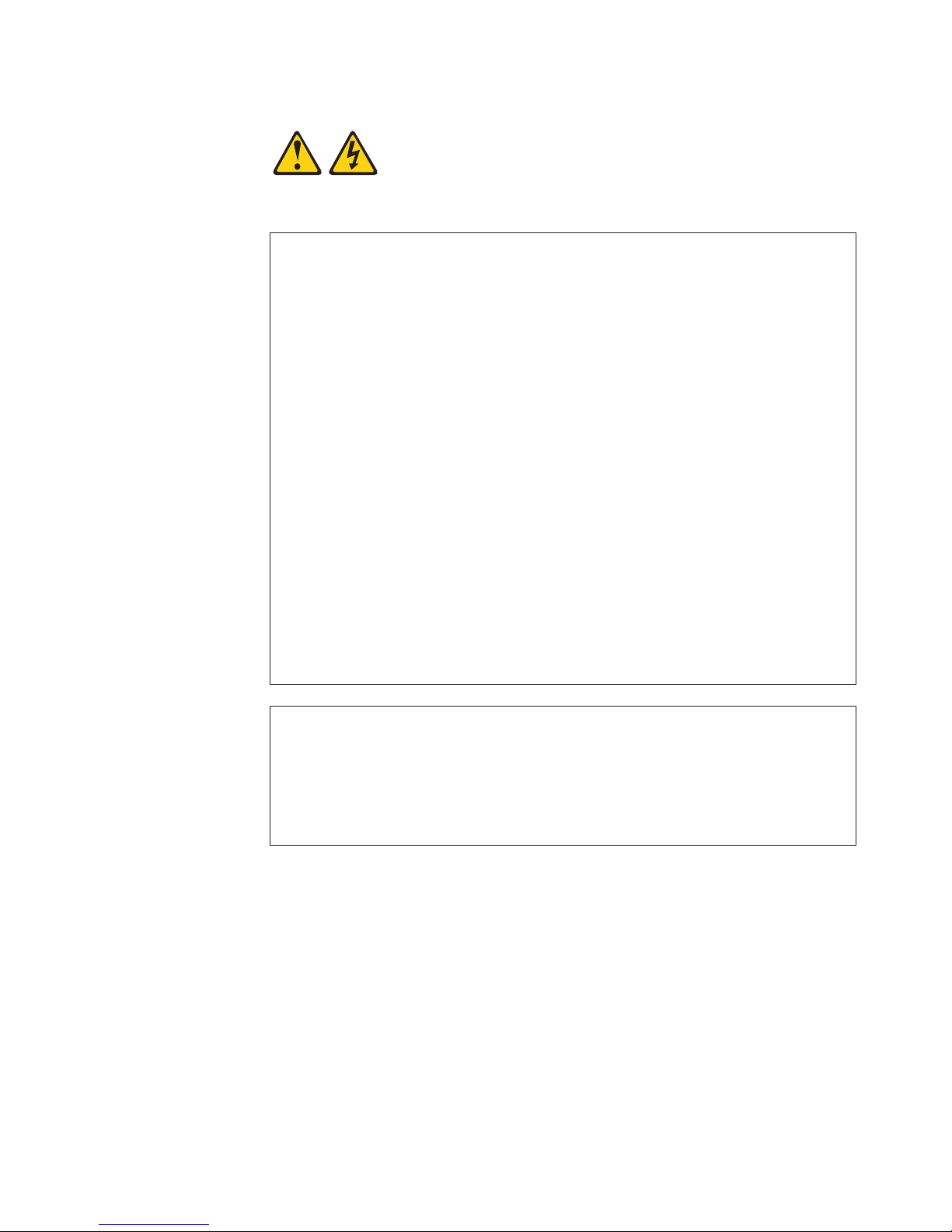
Statement 1:
DANGER
Electrical current from power, telephone, and communication cables is
hazardous.
To avoid a shock hazard:
v Do not connect or disconnect any cables or perform installation,
maintenance, or reconfiguration of this product during an electrical
storm.
v Connect all power cords to a properly wired and grounded electrical
outlet.
v Connect to properly wired outlets any equipment that will be attached to
this product.
v When possible, use one hand only to connect or disconnect signal
cables.
v Never turn on any equipment when there is evidence of fire, water, or
structural damage.
v Disconnect the attached power cords, telecommunications systems,
networks, and modems before you open the device covers, unless
instructed otherwise in the installation and configuration procedures.
v Connect and disconnect cables as described in the following table when
installing, moving, or opening covers on this product or attached
devices.
To Connect: To Disconnect:
1. Turn everything OFF.
2. First, attach all cables to devices.
3. Attach signal cables to connectors.
4. Attach power cords to outlet.
5. Turn device ON.
1. Turn everything OFF.
2. First, remove power cords from outlet.
3. Remove signal cables from connectors.
4. Remove all cables from devices.
Safety ix
Page 12
Statement 2:
CAUTION:
When replacing the lithium battery, use only IBM Part Number 33F8354 or an
equivalent type battery recommended by the manufacturer. If your system has
a module containing a lithium battery, replace it only with the same module
type made by the same manufacturer. The battery contains lithium and can
explode if not properly used, handled, or disposed of.
Do not:
v Throw or immerse into water
v Heat to more than 100°C (212°F)
v Repair or disassemble
Dispose of the battery as required by local ordinances or regulations.
Statement 3:
CAUTION:
When laser products (such as CD-ROMs, DVD drives, fiber optic devices, or
transmitters) are installed, note the following:
v Do not remove the covers. Removing the covers of the laser product could
result in exposure to hazardous laser radiation. There are no serviceable
parts inside the device.
v Use of controls or adjustments or performance of procedures other than
those specified herein might result in hazardous radiation exposure.
DANGER
Some laser products contain an embedded Class 3A or Class 3B laser
diode. Note the following.
Laser radiation when open. Do not stare into the beam, do not view directly
with optical instruments, and avoid direct exposure to the beam.
Class 1 Laser Product
Laser Klasse 1
Laser Klass 1
Luokan 1 Laserlaite
Appareil A Laser de Classe 1
`
x BladeCenter H Type 8852, 7989, and 1886: Installation and User’s Guide
Page 13
Statement 4:
≥ 18 kg (39.7 lb) ≥ 32 kg (70.5 lb) ≥ 55 kg (121.2 lb)
CAUTION:
Use safe practices when lifting.
Statement 5:
CAUTION:
The power control button on the device and the power switch on the power
supply do not turn off the electrical current supplied to the device. The device
also might have more than one power cord. To remove all electrical current
from the device, ensure that all power cords are disconnected from the power
source.
2 / 3 1 / 4
Safety xi
Page 14
Statement 8:
CAUTION:
Never remove the cover on a power supply or any part that has the following
label attached.
Hazardous voltage, current, and energy levels are present inside any
component that has this label attached. There are no serviceable parts inside
these components. If you suspect a problem with one of these parts, contact
a service technician.
Statement 12:
CAUTION:
The following label indicates a hot surface nearby.
Statement 13:
DANGER
Overloading a branch circuit is potentially a fire hazard and a shock hazard
under certain conditions. To avoid these hazards, ensure that your system
electrical requirements do not exceed branch circuit protection
requirements. Refer to the information that is provided with your device for
electrical specifications.
xii BladeCenter H Type 8852, 7989, and 1886: Installation and User’s Guide
Page 15
Statement 20:
CAUTION:
To avoid personal injury, before lifting the unit, remove all the blades to
reduce the weight.
(14X)
164 kg
(360 lbs)
(4X)
(2X)
44 kg
(96 lbs)
Statement 21:
CAUTION:
Hazardous energy is present when the blade is connected to the power
source. Always replace the blade cover before installing the blade.
United Kingdom - Notice to Customers:
This apparatus is approved under approval number NS/G/1234/J/100003 for indirect
connection to public telecommunication systems in the United Kingdom.
Safety xiii
Page 16

xiv BladeCenter H Type 8852, 7989, and 1886: Installation and User’s Guide
Page 17

Chapter 1. Introduction
The IBM®BladeCenter®Type 8852, 7989, and 1886 unit is a high-density,
high-performance rack-mounted server system. The BladeCenter unit provides 14
bays for blade servers and other BladeCenter devices, integrating common
resources that are shared by the blade servers. The use of common resources
provides a small server-system footprint that contains high-performing servers with
minimal cabling. The BladeCenter unit has the following features:
v Hot-swap that enable you to add, remove, or replace blade servers, management
modules, I/O modules, power modules, or blower modules without removing
power from the BladeCenter unit.
v A midplane that connects all BladeCenter components.
v A management module that functions as a system-management processor. There
are two management module bays.
v Power modules that provide redundant power for all BladeCenter components.
There are four power modules that operate in redundant pairs. Each pair
provides power to selected BladeCenter components.
v Blowers that provide cooling for most BladeCenter components. There are two
blower modules.
v There are three fans attached to each power module that provide cooling for the
power modules and other components.
v Ten input/output (I/O) module bays that support external network interface
connections to network resources and other devices.
v A media tray that contains an optical drive and two Universal Serial Bus (USB)
ports that can be used by any blade server.
Note: The optical drive is an option on some BladeCenter units.
This Installation and User’s Guide provides information about the following tasks:
v Defining and recording your BladeCenter network configuration information
v Installing and cabling the BladeCenter unit
v Installing basic BladeCenter unit optional devices:
– Management modules
– I/O modules
– Power modules
– Blower modules
– Blade servers
v Performing basic troubleshooting of the BladeCenter unit
Packaged with the Installation and User’s Guide are software CDs that help you to
configure and manage the BladeCenter unit.
You can obtain up-to-date information about your BladeCenter Type 8852, 7989,
and 1886 unit and other IBM server products at http://www.ibm.com/bladecenter/.
© Copyright IBM Corp. 2010 1
Page 18

Locating and recording BladeCenter unit information
Record information about your BladeCenter unit in the following table. You will need
this information for future reference.
Product name BladeCenter H
Machine type
Model number _____________________________________________
Serial number _____________________________________________
The serial number and model number are on labels on the top, front, and rear of
the chassis.
A set of blank labels comes with each blade server. Record identifying information
on a label and place it on the BladeCenter unit top bezel, just above the blade
server. Do not place the label on the blade server itself or in any way block the
ventilation holes on the blade server.
8852
7989
1886
2 BladeCenter H Type 8852, 7989, and 1886: Installation and User’s Guide
Page 19

Features and specifications
The following table provides a summary of the features and specifications of the
BladeCenter unit. Depending on the model, some features might not be available,
or some specifications might not apply.
Media tray (on front):
v Optical drive (optional)
v Two USB v2.0 ports
v Front system LED panel
Blade bays (on front): 14 hot-swap
blade-server bays
Module bays (on front): Four hot-swap
power-module bays
Module bays (on rear):
v Two hot-swap management-module
bays
v Ten hot-swap I/O-module bays
v Two hot-swap blower bays
Power modules:
v Minimum: Two hot-swap power
modules that are configured for
redundant operation
v Maximum: Four hot-swap power
modules that provide redundancy to
all BladeCenter components
Redundant cooling: Two
variable-speed hot-swap blowers
Management module:
v Minimum: One hot-swap advanced
management module.
v Maximum: Two hot-swap advanced
management modules: one active,
one hot stand-by.
Upgradeable microcode:
v Management-module firmware
v I/O-module firmware (not all I/O module
types)
v Blade-server firmware
Security features:
v Login password for remote connection
v Secure Sockets Layer (SSL) security for
remote management access
Predictive Failure Analysis (PFA) alerts:
v Blowers
v Blade-dependent features
Size (9 U):
v Height: 400.1 mm (15.75 in. or 9 U)
v Depth: 711.2 mm (28 in.)
v Width: 482.6 mm (19 in.)
v Weight:
– Full configured weight with blade
servers: Approximately 158.8 kg (350
lbs)
– Empty chassis without modules or
blade servers: Approximately 40.82
kg (90 lbs)
Environment:
v Air temperature:
– BladeCenter unit on:
- Altitude: 0 to 914 m (3000 ft)
10° to 35°C (50° to 95°F)
- Altitude: 914 m to 2134 m (3000 ft to
7000 ft) 10° to 32°C (50° to 90°F)
– BladeCenter unit off: -40° to 60°C
(-40° to 140°F).
v Humidity: 8% to 80%
v Acoustics: declared sound power level: 7.5
1
bels
Electrical input:
v Sine-wave input (50-60 Hz single-phase)
required
v Input voltage:
– Minimum: 200 V ac
– Maximum: 240 V ac
Heat output: Approximate heat output in
British thermal units (Btu) per hour:
v Minimum configuration: 1024 Btu/hour (300
watts)
v Maximum configuration: 32757 Btu/hour
(9600 watts)
Airflow: Approximate airflow in cubic feet per
minute (cfm):
v Minimum airflow: 450 cfm
v Maximum airflow: 975 cfm
Notes:
1. Government regulations (such as those prescribed by Occupational Safety and Health Administration or European Community
Directives) might govern noise level exposure in the workplace and might apply to you and your server installation. The actual
sound pressure levels in your installation depend on a variety of factors, including the number of racks in the installation; the size,
materials, and configuration of the room where you designate the racks to be installed; the noise levels from other equipment; the
room ambient temperature; and employees' location in relation to the equipment. Compliance with such government regulations
also depends on a variety of additional factors, including the duration of employees' exposure and whether employees wear
hearing protection. It is recommended that you consult qualified experts in this field to determine whether you are in compliance
with the applicable regulations.
The BladeCenter modules
The BladeCenter unit contains the following hot-swap modules:
v Advanced management modules
v I/O modules
v Power modules
v Blower modules
Chapter 1. Introduction 3
Page 20

See “Major components of the BladeCenter H unit” on page 9 for the location of
each module. These modules supply common functions to the blade servers that
are installed in the blade bays in the front of the BladeCenter unit.
The BladeCenter unit and the active management module make optional I/O
devices (optical drive, USB port, keyboard, video, and mouse) available to all the
blade servers, selected by any one blade server at a time.
Advanced management module
The BladeCenter unit comes with one hot-swap management module in
management-module bay 1. You can add a second management-module in
management-module bay 2 to provide redundancy.
The management module is a hot-swap module that you use to configure and
manage BladeCenter components. See the User’s Guide that comes with the
management module for more information.
I/O modules
The BladeCenter unit has 10 hot-swap I/O module bays that are compatible with
three types of I/O modules (see “Rear view” on page 15 for the location of the I/O
module bays). These bays can be used as follows:
v The modules in bays 1 and 2 such as Ethernet switches or pass-thru modules,
provide a communication links for the first and second network interface
controllers (NICs) on each blade server. The modules in these bays must support
Ethernet.
v The modules in bays 3 and 4 can be either of the following types, but the
modules in both bays must be of the same type:
– Switch modules, which provide a communication link for the third and fourth
NICs in each blade server. The modules in these bays must support the type
of network interface that is used in the corresponding blade-server NICs.
When these bays are used this way, they are similar in function to bays 1 and
2.
– Bridge modules, which provide links to bays 7 through 10 that can be used as
additional outputs for the I/O modules in those bays. When these bays are
used this way, the modules in these bays are not directly linked to the blade
servers but bay 3 provides redundancy for the module in bay 5 and bay 4
provides redundancy for bay 6.
v The modules in bays 5 and 6, such as bridge modules, provide links to bays 7
through 10 that can be used as additional outputs for the I/O modules in those
bays. Bays 5 and 6 are not directly linked to the blade servers.
v The modules in bays 7 through 10, such as Infiniband switches, provide
high-speed communication links to the fifth through eighth NICs in each blade
server. The modules in these bays must support the type of network interface
that is used in the corresponding blade-server NICs.
Blade servers
The BladeCenter unit provides 14 bays for blade servers or other BladeCenter
devices. A blade server is a hot-swap, independent server with its own processors,
memory, storage, network controllers, operating system, and applications. The blade
server is installed in a bay in the BladeCenter unit and shares power, fans,
switches, and ports with other blade servers.
4 BladeCenter H Type 8852, 7989, and 1886: Installation and User’s Guide
Page 21

Power modules
Blower modules
The BladeCenter unit comes with two or four hot-swap power modules.
Power modules are needed in bays 1 and 2 if you install blade servers in blade
bays 1 through 7 or if you install I/O modules in I/O module bays 1 through 4 or 7
through 10.
Power modules are needed in power module bays 3 and 4 if you install blade
servers in blade bays 8 through 14 or if you install I/O modules in any of I/O
module bays 5 through 10.
Each pair of power modules is redundant. If either power module fails, the
remaining power module continues to supply power, but there is no redundancy; the
failed power module must be replaced as soon as possible.
The BladeCenter unit comes with two hot-swap blowers for cooling redundancy. The
blower speeds vary depending on the ambient air temperature at the front of the
BladeCenter unit and the temperature of internal BladeCenter components. If the
ambient temperature is 25°C (77°F) or below, the BladeCenter unit blowers will run
at their minimum rotational speed, increasing their speed as required to control
internal BladeCenter temperature. If the ambient temperature is above 25°C (77°F),
the blowers will run faster, increasing their speed as required to control internal
BladeCenter unit temperature. If a blower fails, the operating speed of the
remaining blower might increase and continue to cool the BladeCenter unit and
blade servers. Replace a failed blower as soon as possible, to restore cooling
redundancy.
Your BladeCenter might be equipped with standard blower modules (part number
44E5083), or it might be equipped with high-efficiency blower modules (part number
68Y8205). The standard and high-efficiency blower modules are not
interchangeable and should not be mixed in the same BladeCenter unit.
For a list of supported options for the BladeCenter, see the ServerProven
http://www.ibm.com/servers/eserver/serverproven/compat/us/.
The IBM Documentation CD
The IBM BladeCenter Documentation CD contains documentation for your
BladeCenter unit in Portable Document Format (PDF) and includes the IBM
Documentation Browser to help you find information quickly.
Hardware and software requirements
The IBM BladeCenter Documentation CD requires the following minimum hardware
and software:
v Microsoft Windows NT 4.0 (with Service Pack 3 or later), Windows 2000, or Red
Hat Linux
v 100 MHz microprocessor
v 32 MB RAM
v Adobe Acrobat Reader 3.0 (or later) or xpdf, which comes with Linux operating
systems. Acrobat Reader software is included on the CD, and you can install it
when you run the Documentation Browser.
®
list at
Chapter 1. Introduction 5
Page 22

Using the Documentation Browser
Use the Documentation Browser to browse the contents of the CD, read brief
descriptions of the documents, and view documents, using Adobe Acrobat Reader
or xpdf. The Documentation Browser automatically detects the regional settings in
use in your system and presents the information in the language for that region (if
available). If a topic is not available in the language for that region, the English
version is displayed.
Use one of the following procedures to start the Documentation Browser:
v If Autostart is enabled, insert the CD into the drive. The Documentation Browser
starts automatically.
v If Autostart is disabled or is not enabled for all users:
– If you are using a Windows operating system, insert the CD into the drive;
then, click Start → Run.IntheOpen field, type
e:\win32.bat
where e is the drive letter of your optical drive, and click OK.
– If you are using a Red Hat Linux, insert the CD into the drive and run the
following command from the /mnt/cdrom directory:
sh runlinux.sh
Select your computer from the Product menu. The Available Topics list displays
all the documents for your BladeCenter product. Some documents might be in
folders. A plus sign (+) indicates each folder or document that has additional topics
under it. Click the plus sign to display the additional documents.
When you select a document, a description of the document appears under Topic
Description. To select more than one document, press and hold the Ctrl key while
you select the documents. Click View Book to view the selected document or
documents in Acrobat Reader or xpdf. If you selected more than one document, all
the selected documents are opened in Acrobat Reader or xpdf.
To search all the documents, type a word or word string in the Search field and
click Search. The documents in which the word or word string appears are listed in
order of the most occurrences. Click a document to view it, and press Ctrl+F to use
the Acrobat search function or press Alt+F to use the xpdf search function within the
document.
Click Help for detailed information about using the Documentation Browser.
Related documentation
In addition to this Installation and User’s Guide, the following related documentation
is provided in Portable Document Format (PDF) at http://www.ibm.com/support/ or
on the BladeCenter Documentation CD that comes with your BladeCenter unit:
v Warranty: This document contains information about the terms of the warranty.
v Safety Information: This document contains translated caution and danger
statements. Each caution and danger statement that appears in the
documentation has a number that you can use to locate the corresponding
statement in your language in the Safety Information document.
v BladeCenter H Rack Installation Instructions: This document contains instructions
for installing the BladeCenter unit in a rack.
6 BladeCenter H Type 8852, 7989, and 1886: Installation and User’s Guide
Page 23

v BladeCenter Advanced Management Module User’s Guide: This document
provides general information about your management module, including
information about features, how to configure the management module, and how
to get help.
v BladeCenter Advanced Management Module Command-Line Interface Reference
Guide: This document explains how to use the management-module
command-line interface to directly access BladeCenter management functions as
an alternative to using the Web-based user interface. The command-line interface
also provides access to the text-console command prompt on each blade server
through a Serial over LAN (SOL) connection.
v BladeCenter H Problem Determination and Service Guide: This document
contains the information to help you solve problems, and it contains information
for service technicians.
v BladeCenter Advanced Management Module Installation Guide: This document
contains instructions for installing the management module in the BladeCenter
unit and creating the initial configuration.
v BladeCenter Advanced Management Module Messages Guide
This document contains a complete list of all non-device specific events and
recommended actions, sorted by event ID. Device specific event information is in
the documentation for the device.
v Serial over LAN Setup Guide
This document explains how to update and configure BladeCenter components
for Serial over LAN (SOL) operation. The SOL connection provides access to the
text-console command prompt on each blade server and enables the blade
servers to be managed from a remote location.
Additional documents might be included on the IBM BladeCenter Documentation
CD.
Chapter 1. Introduction 7
Page 24

Notices and statements in this document
The caution and danger statements that appear in this document are also in the
multilingual Safety Information document, which is on the IBM BladeCenter
Documentation CD. Each statement is numbered for reference to the corresponding
statement in the Safety Information document.
The following notices and statements are used in this document:
v Note: These notices provide important tips, guidance, or advice.
v Important: These notices provide information or advice that might help you avoid
inconvenient or problem situations.
v Attention: These notices indicate possible damage to programs, devices, or
data. An attention notice is placed just before the instruction or situation in which
damage could occur.
v Caution: These statements indicate situations that can be potentially hazardous
to you. A caution statement is placed just before the description of a potentially
hazardous procedure step or situation.
v Danger: These statements indicate situations that can be potentially lethal or
extremely hazardous to you. A danger statement is placed just before the
description of a potentially lethal or extremely hazardous procedure step or
situation.
8 BladeCenter H Type 8852, 7989, and 1886: Installation and User’s Guide
Page 25
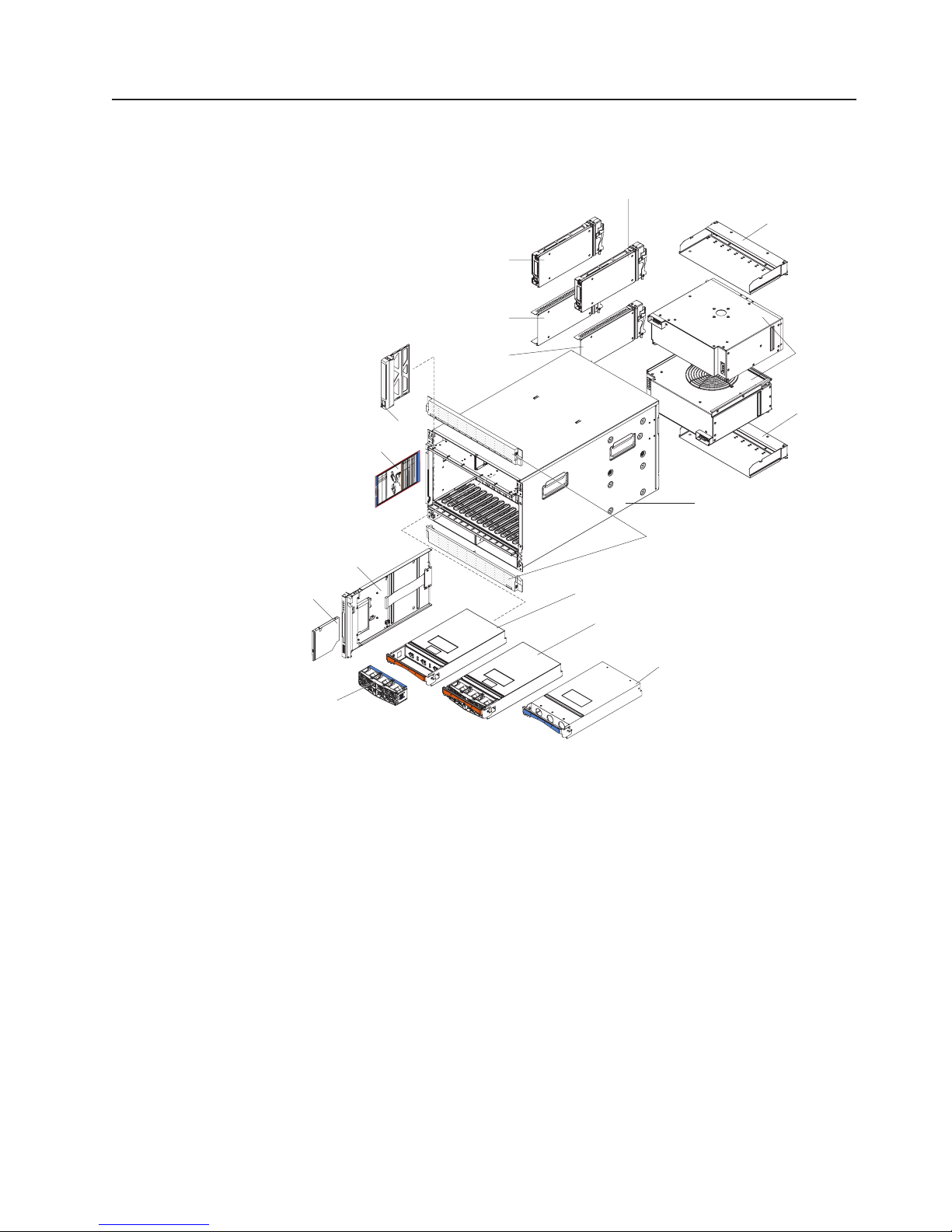
Major components of the BladeCenter H unit
The following illustrations show the locations of the major components in the
BladeCenter unit.
Management module
Management module
filler
I/O module
filler
Blade filler
System service
card
Media tray
S
e
e
h
a
r
d
w
S
a
e
r
e
e
f
h
o
ServiceInformation
a
r
r
a
d
c
w
t
u
a
a
L
r
C
e
l
BladeCenter
D
l
o
f
i
o
c
g
B
r
a
la
a
t
i
h
c
o
d
t
n
u
e
t
a
o
C
l
f
e
l
P
L
o
n
E
c
t
a
B
D
e
a
t
l
i
r
s
o
a
t
S
n
a
d
n
y
h
e
o
d
s
f
S
t
L
b
e
e
E
u
D
m
r
t
D
t
v
o
L
s
e
i
n
r
a
a
E
s
n
.
C
D
d
H
g
o
3
P
b
n
H
m
r
n
u
a
(
o
t
d
®
a
o
r
t
n
o
t
o
n
p
o
p
d
o
e
t
l
d
e
n
o
u
l
P
l
s
n
-
we
l
-
e
s
AC
e
.
Power Module LEDs
)
a
S
P
n
t
r
r
e
O
i
w
i
m
l
K
c
a
D
S
a
r
s
y
C
e
p
c
O
o
K
n
P
d
a
r
o
y
w
e
4
r
m
t
h
o
M
p
d
o
u
we
l
e
o
r
d
u
l
D
e
e
s
c
r
i
p
t
i
o
n
a
n
d
A
c
t
i
o
n
I/O module
Bezel, top and bottom
Chassis
I/O module
filler
Blower
module
I/O module
filler
Optical
drive
Fan pack
Power module, 2900 W
Power module, 2980 W
(With integrated fan pack)
Power module filler
Chapter 1. Introduction 9
Page 26

10 BladeCenter H Type 8852, 7989, and 1886: Installation and User’s Guide
Page 27

Chapter 2. BladeCenter unit power, controls, and indicators
This section describes the controls and light-emitting diodes (LEDs) and how to
start and shut down the BladeCenter unit.
Supplying power to the BladeCenter unit
To supply power to the BladeCenter unit, connect one end of each power cord to a
power connector on the rear of the BladeCenter unit and the other end of each
power cord to a 220-volt power distribution unit or appropriate electrical outlet. The
BladeCenter unit does not have a power switch.
The blade servers in the BladeCenter unit are connected to power but are not
turned on. After the BladeCenter unit has power, depending on the configuration
settings, the blade servers might have to be individually turned on.
Disconnecting power from the BladeCenter unit
You can shut down the BladeCenter unit by turning off the blade servers and
disconnecting the BladeCenter unit from the power source.
To disconnect power from the BladeCenter unit, complete the following steps:
1. Shut down each blade server. See the documentation that comes with your
blade servers for the procedure for shutting down the operating system.
Statement 5:
CAUTION:
The power control button on the device and the power switch on the
power supply do not turn off the electrical current supplied to the device.
The device also might have more than one power cord. To remove all
electrical current from the device, ensure that all power cords are
disconnected from the power source.
2 / 3 1 / 4
2. Disconnect all power cords on the BladeCenter unit from the power connectors.
Attention: The power cords on the rear of the BladeCenter chassis are not
approved to be connected or disconnected under power. You must first
disconnect the power cords from the ac power source; then, you can remove
the power cords from the chassis connectors.
Note: After you disconnect the BladeCenter unit from power, wait at least 5
seconds before you connect the BladeCenter unit to power again.
© Copyright IBM Corp. 2010 11
Page 28

BladeCenter components, controls, and LEDs
This section identifies the components, controls, and LEDs on the front and rear of
the BladeCenter unit.
Front view
This section identifies the components, controls, and LEDs on the front of the
BladeCenter unit.
Power module 1 Power module
bay 3
Blade
server
control
panel
System
service
cards
Power module 2 Power module
Media tray
Front system
LED panel
Optical drive
activity LED
Optical drive
eject button
USB connectors
bay 4
Power modules
The following illustration shows the LEDs on each power module.
AC power LED
Power module error LED
DC power LED
The LEDs on each power module indicate the condition of the power module and
fan pack.
Note: The orientation of the power module shown in the illustration is for one of the
top power-modules. The orientation for modules in the bottom power-module
bays is rotated 180°.
v DC power LED: When this green LED is lit, the dc output from the power
module to the other components and blade servers is present and within
specifications. During typical operation, both the ac power and dc power LEDs
are lit.
v AC power LED: When this green LED is lit, ac input to the power module is
present and within specifications. During typical operation, both the ac power and
dc power LEDs are lit.
12 BladeCenter H Type 8852, 7989, and 1886: Installation and User’s Guide
Fan error LED
Page 29

v Power module error LED: When this amber LED is lit, a power module failure
has occurred and it is not operating within specifications.
v Fan error LED: When this amber LED is lit, a fan pack has failed and is not
operating within specifications.
Media tray
The media tray contains the following:
v Front system LED panel
The LEDs on this panel provide status information for your BladeCenter unit.
Power-on
Location
Over-temperature
Information
System error
Note: You can turn off the location LED and the information LED through the
management module.
– Power-on: When this green LED is lit, power is present in the BladeCenter
unit. When this LED is off, the power subsystem, the ac power, or the LED
has failed, or the management module is not present, not functioning or the
media tray is not fully seated.
Attention: If the power-on LED is off, it does not mean that there is no
electrical current present in the BladeCenter unit. The LED might be burned
out. To remove all electrical current from the BladeCenter unit, you must
disconnect all power cords from the BladeCenter unit.
– Location: When this blue LED is lit or flashing, it has been turned on by the
system administrator to aid in visually locating the BladeCenter unit. If a blade
server requires attention, the location LED on the blade server usually will
also be lit. After the BladeCenter unit has been located, you can have the
system administrator turn off the location LED.
– Over-temperature: When this amber LED is lit, the temperature in the
BladeCenter unit exceeds the temperature limits, or a blade server reports an
over-temperature condition. The BladeCenter unit might have already taken
corrective action, such as increasing the blower speed. This LED turns off
automatically when there is no longer an over-temperature condition.
– Information: When this amber LED is lit, a noncritical event has occurred that
requires attention, such as the wrong I/O module inserted in a bay or power
demands that exceed the capacity of power modules that are currently
installed. The event is recorded in the event log. Check the LEDs on the
BladeCenter unit and the blade servers to isolate the component. After the
situation is corrected, have the system administrator turn off the information
LED.
Chapter 2. BladeCenter unit power, controls, and indicators 13
Page 30

– System-error: When this amber LED is lit, it indicates that a system error has
occurred, such as a failed module or a system error in a blade server. An LED
on one of the components or on a blade server is also lit to further isolate the
error.
v Optical drive activity LED: When this LED is lit, it indicates that the optical drive
is in use.
v Optical drive eject button: Press this button to release a disc from the optical
drive.
v USB connectors: Use these connectors to attach USB devices.
System service cards
These cards contain system service instructions and a writable area. They slide in
and out of the storage location on the left side of the BladeCenter unit.
Blade server control panel
This panel contains indicators and controls for the blade server. See the
documentation that comes with your blade server for information about the blade
server control panel.
14 BladeCenter H Type 8852, 7989, and 1886: Installation and User’s Guide
Page 31

Rear view
This section identifies the components, connectors, and LEDs on the rear of the
BladeCenter unit.
I/O module bay 7
Power connector 2
I/O module bay 8
I/O module bay 1
I/O module bay 5
Power connector 1
Management
module 1
I/O module bay 3
Blower module 1
error LED
Blower module 1
I/O module bay 2
I/O module bay 6
Blower module 2
error LED
Rear system
LED panel
Serial connector
I/O module bay 9
I/O module bay 10
Management
module bay 2
I/O module bay 4
Blower module 2
Power connectors
Connect a power cord from each power connector to a 220-volt power distribution
unit or appropriate electrical outlet. See your specific power cable document for
more information.
I/O modules
See the documentation that comes with each I/O module for a description of the
LEDs and connectors on the I/O module.
Management modules
See the documentation that comes with each management module for a description
of the LEDs and connectors on the module.
Blower modules
When the amber LED on a blower module is lit, an error has been detected in the
blower or power to the blower is not present. The system-error LEDs on the
BladeCenter system LED panels are also lit.
Serial connector
This connector provides direct access to the serial ports on each of the 14 blade
server bays. Use this connector to attach the optional serial port breakout cable and
connect up to 14 local consoles. See the documentation supplied with your blade
server to see if it supports this cable.
Rear system LED panel
The LEDs on this panel provide status information. These LEDs duplicate the LEDs
in the front system LED panel (see “Front system LED panel” on page 13 for more
information).
Chapter 2. BladeCenter unit power, controls, and indicators 15
Page 32

16 BladeCenter H Type 8852, 7989, and 1886: Installation and User’s Guide
Page 33

Chapter 3. Installing the BladeCenter unit and options
This chapter provides instructions for installing the BladeCenter unit into a rack and
adding optional devices to your BladeCenter unit. Some removal instructions are
provided in case you have to remove one device to install another.
Installation checklist
Before you can use the BladeCenter unit, you must set up and configure the
BladeCenter unit, and install and configure the required components in the
BladeCenter unit. If you have not already done so, perform the activities on the
following checklist:
__ 1. Set up the rack in which you will install the BladeCenter unit. See the
documentation that comes with your rack.
__ 2. Determine the BladeCenter unit configuration settings, such as the IP
address, network address, and Wake on LAN setting. Record the
BladeCenter configuration setting information in Appendix A, “BladeCenter
management-module configuration worksheet,” on page 47. See the
BladeCenter Management Module User’s Guide that comes with your
management module for instructions to configure an IP address.
__ 3. Remove any modules that come installed in the BladeCenter unit to reduce
the weight of the unit you install into the rack. See “Removing components
before rack installation” on page 19 for instructions.
__ 4. Install the BladeCenter unit into the rack. See the BladeCenter H Rack
Installation Instructions.
__ 5. Reinstall the removed modules in the BladeCenter unit. Make sure that the
BladeCenter unit has adequate power to support all of the installed
components. The BladeCenter unit must contain either two or four power
modules.
__ 6. Install the required BladeCenter unit components.
__ 7. Make sure that the latest level of firmware is installed on all of the
BladeCenter components. See http://www.ibm.com/support/ for additional
information.
__ 8. Configure the management module in the BladeCenter unit. See the
BladeCenter Advanced Management Module Installation Guide that comes
with your management module for information and instructions.
__ 9. Configure the I/O modules in the BladeCenter unit. See the documentation
for your I/O modules for configuration information.
__ 10. Configure the blade servers. See the Installation and User's Guide that
comes with your blade server for information and instructions.
Installing the BladeCenter unit in a rack
Install the BladeCenter unit in a rack before you install any modules or blade
servers in the BladeCenter unit. If your BladeCenter unit is preconfigured with blade
servers, power modules, management modules, and blowers already installed,
remove them first to reduce the weight. Detailed instructions for installing a
BladeCenter unit in a rack are in the BladeCenter H Rack Installation Instructions
that come with the BladeCenter unit.
© Copyright IBM Corp. 2010 17
Page 34

Installation guidelines
Before you install options in the BladeCenter unit, read the following information:
v Read the safety information that begins on page vii and the guidelines in
“Handling static-sensitive devices.” This information will help you work safely.
v Orange on a component or an orange label on or near a component indicates
that the component can be hot-swapped, which means that you can remove or
install the component while the BladeCenter unit is running. (Orange can also
indicate touch points on hot-swap components.) See the instructions for removing
or installing a specific hot-swap component for any additional procedures that
you might have to perform before you remove or install the component.
v You do not have to disconnect the BladeCenter unit from power to install or
replace any of the hot-swap modules in the BladeCenter unit. You must shut
down the operating system and turn off a hot-swap blade server before you
remove the blade server, but you do not have to shut down the BladeCenter unit
itself.
v Blue on a component indicates touch points where you can grip the component
to remove it from or install it in the BladeCenter unit, open and close a latch, and
so on.
v For a list of supported options for the BladeCenter unit, see
http://www.ibm.com/bladecenter/
System reliability guidelines
To help ensure proper cooling and system reliability, make sure that the following
requirements are met:
v Each of the module bays on the rear of the BladeCenter unit has either a module
or a module filler installed.
v Each of the blade bays on the front of the BladeCenter unit has either a blade
server or a blade filler installed.
v Each of the drive bays in a blade-server storage expansion option has either a
hot-swap drive or a filler panel installed.
v A removed hot-swap module, blade server, or drive is replaced within 1 minute of
removal.
v Cables for the optional modules are routed according to the illustrations and
instructions in this document.
v A failed blower is replaced as soon as possible, to restore cooling redundancy.
Handling static-sensitive devices
Attention: Static electricity can damage the BladeCenter unit and other electronic
devices. To avoid damage, keep static-sensitive devices in their static-protective
packages until you are ready to install them.
To reduce the possibility of electrostatic discharge, observe the following
precautions:
v Limit your movement. Movement can cause static electricity to build up around
you.
v Handle the device carefully, holding it by its edges or its frame.
v Do not touch solder joints, pins, or exposed printed circuitry.
v Do not leave the device where others can handle and damage it.
18 BladeCenter H Type 8852, 7989, and 1886: Installation and User’s Guide
Page 35

v While the device is still in its static-protective package, touch it to an unpainted
metal part of the BladeCenter unit or rack for at least 2 seconds. This drains
static electricity from the package and from your body.
v Remove the device from its package and install it immediately without setting
down. If it is necessary to set down the device, put it back into its
static-protective package.
v Take additional care when handling devices during cold weather. Heating reduces
indoor humidity and increases static electricity.
Removing components before rack installation
Attention: See the BladeCenter H Problem Determination and Service Guide for
removing components from the BladeCenter unit when the unit is connected to
power.
Use the following procedures to remove components from the BladeCenter unit
before you install it in a rack and connect to power.
Removing a power module
To remove a power module, complete the following steps.
Release buttons
1. Read the safety information that begins on page v and “Installation guidelines”
on page 18.
2. Press the blue release button on each end of the bezel.
3. Pull the bezel away from the BladeCenter unit.
Release buttons
Chapter 3. Installing the BladeCenter unit and options 19
Page 36

3rd power
module
Handle
(open)
Power-module
filler
Handle
(open)
4th power
module
4. Open the power-module handle, using one of the following procedures:
v For a power module in one of the upper power-module bays, push the inner
handle release to the right; then, pull the handle up to the open position.
v For a power module in one of the lower power-module bays, push the inner
handle release to the left; then, pull the handle down to the open position.
5. Use the handle to pull the module out of the bay.
20 BladeCenter H Type 8852, 7989, and 1886: Installation and User’s Guide
Page 37

Removing a blade server
Attention: Note the bay number. Reinstalling a blade server into a different bay
than the one from which it was removed could have unintended consequences.
Some configuration information and update options are established according to
bay number.
To remove a blade server, complete the following steps.
Release handles
(open)
1. Read the safety information that begins on page v and “Installation guidelines”
on page 18.
2. Move the two release handles to the open position. The blade server moves out
of the bay approximately 0.6 cm (0.25 inch).
3. Pull the blade server out of the bay.
Removing a management module
To remove a management module or filler, complete the following steps.
Management
module
1. Read the safety information that begins on page v and “Installation guidelines”
on page 18.
2. Pull the module release handle to the open position. The module moves out of
the bay approximately 0.6 cm (0.25 inch).
3. Slide the module out of the bay.
Module
filler
Release handle
(open)
Chapter 3. Installing the BladeCenter unit and options 21
Page 38

Removing a blower module
Your BladeCenter might be equipped with standard blower modules (part number
44E5083), or it might be equipped with high-efficiency blower modules (part number
68Y8205). The standard and high-efficiency blower modules are not
interchangeable and should not be mixed in the same BladeCenter unit.
To remove a blower module, complete the following steps.
Release button
1. Read the safety information that begins on page v and “Installation guidelines”
on page 18.
2. Press the release button on the blower handle and rotate the handle to the
open position (rotate to the right for the upper blower module or to the left for
the lower blower module).
3. Using the handle, pull the blower module out of the bay.
Handle (open)
Removing an I/O module
To remove an I/O module or module filler, complete the following steps.
I/O
module
Release handle
(open)
1. Read the safety information that begins on page v and “Installation guidelines”
on page 18.
Single
module
filler
Module
filler
Double
module
filler
I/O module
Release handles
(open)
22 BladeCenter H Type 8852, 7989, and 1886: Installation and User’s Guide
Page 39

2. Pull the release handle or handles to the open position. The module moves out
3. Slide the module out of the bay.
Removing a bezel
When working with some devices, such as the media tray and power modules, you
must first remove the top or bottom bezels to access the devices.
To remove either bezel, complete the following steps.
of the bay approximately 0.6 cm (0.25 inch).
Note: The modules and fillers in I/O bays 1 through 6 each have one release
handle; the modules and fillers in I/O bays 7 through 10 each have two
release handles.
Release buttons
Release buttons
1. Read the safety information that begins on page v and “Installation guidelines”
on page 18.
2. Press the blue release button on each end of the bezel.
3. Pull the bezel away from the BladeCenter unit.
Chapter 3. Installing the BladeCenter unit and options 23
Page 40

Removing an optical drive filler
To remove an optical drive filler, complete the following steps.
Retainer clip
Optical drive
retainer tab
Note: These instructions assume that the BladeCenter unit is connected to power.
1. Read the safety information that begins on page v and “Installation guidelines”
on page 18.
2. Remove the top and bottom bezels (see “Removing a bezel” on page 23).
3. Press the release tabs on the top and bottom of the media tray; then, pull the
tray out of the BladeCenter unit.
4. Place the media tray on a clean, static-free surface with the circuit board and
optical drive filler facing up.
Attention: To prevent damage to the circuit board, do not touch or apply
pressure to the circuit board or any of its components.
5. Press the optical drive filler retainer tab and slide the optical drive filler out of
the media tray.
6. Remove the retainer clip from the side of the optical drive filler.
Installing components
The following procedures are for reinstalling components or installing optional
devices in the BladeCenter unit once the rack installation is complete.
Media tray
release tabs
Installing a blower module
Your BladeCenter might be equipped with standard blower modules (part number
44E5083), or it might be equipped with high-efficiency blower modules (part number
68Y8205). The standard and high-efficiency blower modules are not
interchangeable and should not be mixed in the same BladeCenter unit.
For a list of supported options for the BladeCenter, see the ServerProven
http://www.ibm.com/servers/eserver/serverproven/compat/us/.
24 BladeCenter H Type 8852, 7989, and 1886: Installation and User’s Guide
®
list at
Page 41

Note: Government regulations (such as those prescribed by Occupational Safety
and Health Administration or European Community Directives) might govern
noise level exposure in the workplace and might apply to you and your
server installation. The actual sound pressure levels in your installation
depend on a variety of factors, including the number of racks in the
installation; the size, materials, and configuration of the room where you
designate the racks to be installed; the noise levels from other equipment;
the room ambient temperature; and employees' location in relation to the
equipment. Compliance with such government regulations also depends on a
variety of additional factors, including the duration of employees' exposure
and whether employees wear hearing protection. It is recommended that you
consult qualified experts in this field to determine whether you are in
compliance with the applicable regulations.
To install a blower module, complete the following steps.
Handle (open)
Release button
1. Read the safety information that begins on page v and “Installation guidelines”
on page 18.
2. Make sure that the handle on the blower module is in the open position.
3. Orient the blower module to the selected blower-module bay:
v For the upper bay, the handle must be on the right.
v For the lower bay, the handle must be on the left.
4. Slide the module into the bay until it stops; then, push the handle to the closed
position.
Chapter 3. Installing the BladeCenter unit and options 25
Page 42

Installing a management module
To install a management module, complete the following steps.
Module
filler
Management
module
Release handle
(open)
1. Remove the module filler if one is installed.
2. Make sure that the release handle on the module is in the open position.
3. Slide the module into the module bay until it stops.
4. Push the release handle on the module to the closed position.
5. Connect any cables to the module.
6. If the BladeCenter unit is connected to power:
v Make sure that the OK LED on the module is lit.
v If this is a redundant management module, wait at least 45 minutes for the
modules to copy.
26 BladeCenter H Type 8852, 7989, and 1886: Installation and User’s Guide
Page 43

Installing an I/O module
The BladeCenter unit has 10 hot-swap I/O-module bays that are compatible with
three types of I/O modules (see “Major components of the BladeCenter H unit” on
page 9 for the location of the I/O module bays).
Note: Before you install a new I/O module, read the documentation that comes
with the module for detailed instructions.
To install an I/O module, complete the following steps.
Release handle
(open)
I/O
module
Single
module
filler
Module
filler
Double
module
filler
I/O module
Release handles
(open)
1. Remove the module filler if one is installed.
2. Make sure that the release handles are in the open position.
Note: The modules and fillers in I/O bays 1 through 6 each have one release
handle; the modules and fillers in I/O bays 7 through 10 each have two
release handles.
3. Slide the module into the module bay until it stops.
4. Push the release handle or handles to the closed position.
5. Connect all cables to the module.
Chapter 3. Installing the BladeCenter unit and options 27
Page 44

Installing a power module
Two types of power modules are supported for your BladeCenter, 2900W power
modules with removable fan pack and 2980W high-efficiency power modules with
integrated fan pack. The IBM 2980-watt power modules for BladeCenter
more efficient than the 2900W power modules, using less power without sacrificing
performance. The 2900W and 2980W high-efficiency power modules are not
interchangeable within the same power domain of the chassis. A power module
configuration is supported only if the two power modules are matched within the
same power domain:
v Power modules 1 and 2 provide power for domain A (blade slots 1 to 7)
v Power modules 3 and 4 provide power for domain B (blade slots 8 to 14)
The following is an example of a supported configuration:
v Domain A: Power Module 1; 2900W, Power Module 2; 2900W
v Domain B: Power Module 3; 2980W, Power Module 4; 2980W
This is an example of a non-supported configuration:
v Domain A: Power Module 1; 2900W, Power Module 2; 2980W
v Domain B: Power Module 3; 2900W, Power Module 4; 2980W
Attention: Failed power modules should only be replaced with the same type of
power module.
Note: The 2980W high-efficiency power modules are identified by a label on the
power module handle. Remove the top or bottom bezel as needed to access
the power module handle. 2900W power modules do not have this label.
®
H are
2980 W label
28 BladeCenter H Type 8852, 7989, and 1886: Installation and User’s Guide
2980 W High
Efficiency label
Page 45

To install a power module, complete the following steps.
3rd power
module
Handle
(open)
Power-module
filler
Handle
(open)
4th power
module
1. Remove the module filler if one is installed.
2. Make sure that the handle on the power module is in the open position.
3. Orient the new power module to the selected power-module bay:
v For the upper power-module bays, the rear connector on the power module
must be facing down.
v For the lower power-module bays, the rear connector on the power module
must be facing up.
4. Slide the module into the bay until it stops; then, push the handle to the closed
position.
Release buttons
5. Align the blue tabs on the ends of the bezel with the corresponding holes in the
front of the BladeCenter unit.
6. Firmly press the bezel into the BladeCenter unit until the tabs lock it into place.
Release buttons
Chapter 3. Installing the BladeCenter unit and options 29
Page 46

Installing an optical drive
To install an optical drive, complete the following steps.
Retainer clip
Optical drive
retainer tab
Media tray
release tabs
Note: These instructions assume that the BladeCenter unit is connected to power.
1. Remove the media tray and optical drive filler (see “Removing an optical drive
filler” on page 24).
2. Make sure that the media tray is on a clean, static-free surface with the circuit
board facing up.
Attention: To prevent damage to the circuit board, do not touch or apply
pressure to the circuit board or any of its components.
3. Install the retainer clip on the side of the optical drive.
4. Carefully slide the optical drive into the bay on the media tray until it fully
engages the connector and the retainer tab locks into place.
5. Carefully slide the media tray into the BladeCenter unit until the release tabs
lock it into place.
6. Install the top and bottom bezels (see “Installing a bezel” on page 31).
30 BladeCenter H Type 8852, 7989, and 1886: Installation and User’s Guide
Page 47

Installing a bezel
To install either the top or bottom bezel, complete the following steps.
1. Align the blue tabs on the ends of the bezel with the corresponding holes in the
2. Firmly press the bezel into the BladeCenter unit until the tabs lock it into place.
Release buttons
Release buttons
front of the BladeCenter unit.
Installing a blade server
Statement 21:
CAUTION:
Hazardous energy is present when the blade is connected to the power
source. Always replace the blade cover before installing the blade.
Attention: If this is the initial installation of a blade server in the BladeCenter unit,
you must configure the blade server with the blade-server Configuration/Setup
Utility program and install the blade-server operating system. See the
documentation that comes with the blade server for instructions.
To install a blade server, complete the following steps.
Chapter 3. Installing the BladeCenter unit and options 31
Page 48

Release handles
(open)
1. Select the bay for the blade server.
Notes:
a. Depending on the blade-server type and the optional devices that are
installed in it, two or more adjacent bays might be required.
b. When any blade server or device is in blade bays 8 through 14, power
modules must be present in all four power bays.
2. Remove the filler from the bay, if one is installed.
Attention: To help ensure proper cooling, performance and system reliability,
do not operate the BladeCenter unit for more than 1 minute without either a
blade server or a blade filler installed in each blade bay.
3. Make sure that the two release handles are in the open position.
4. Slide the blade server into the bay until it stops.
5. Push the two release handles to the closed position.
6. Make sure that the blade server is receiving power. See the documentation that
comes with the blade server for instructions.
7. If this is a new blade server, write identifying information on one of the user
labels that come with the blade server; then, place the label on the BladeCenter
unit top bezel just above the blade server.
Important: Do not place the label on the blade server or in any way block the
ventilation holes on the BladeCenter unit bezel.
Completing the installation
After you connect the cables to the modules and route the cables (see the cable
routing instructions supplied with the rack if necessary), do the following to start the
BladeCenter unit and verify that it is working correctly.
1. Supply power to the BladeCenter unit by connecting the power cords to a
220-volt power distribution unit or appropriate electrical outlets.
2. Make sure that the following LEDs are lit and indicate that the device is working
properly.
v dc power and ac power LEDs on each power module.
v OK LED on each management module.
v OK LED on each I/O module.
3. Make sure that the power-on LED on each blade server is lit, either steady or
flashing.
32 BladeCenter H Type 8852, 7989, and 1886: Installation and User’s Guide
Page 49

See Chapter 2, “BladeCenter unit power, controls, and indicators,” on page 11 for
information about the location of the LEDs on the modules. See the documentation
that comes with the blade servers for the location of the LEDs on the blade servers.
Chapter 3. Installing the BladeCenter unit and options 33
Page 50

34 BladeCenter H Type 8852, 7989, and 1886: Installation and User’s Guide
Page 51

Chapter 4. Configuration and networking guidelines
The BladeCenter components are configured and managed through a management
module. Depending on your management module type, you can configure the
management module and the BladeCenter unit components through a local or
remote connection and management-module user interfaces or other system
management tools. See your management-module documentation for instructions
for configuring the BladeCenter unit.
Configuring the BladeCenter unit
General configuration of the BladeCenter unit and installed components is
performed through the management module. See the BladeCenter Management
Module User’s Guide and the BladeCenter Management Module Command-Line
Interface Reference Guide for your management module for information and
instructions. Some devices in the BladeCenter unit, such as I/O modules and blade
servers, might also require additional configuration. See the documentation that
comes with each device for information and instructions.
Configuring the management module
All management modules preconfigured with the same static IP address. You can
use the management module to assign a new static IP address. To establish
connectivity, the management module attempts to use Dynamic Host Configuration
Protocol (DHCP) to acquire its initial IP address for the management-module
Ethernet port. If DHCP is not installed or is enabled and fails, the management
module uses the static IP address. Use the management module to configure other
BladeCenter component settings, such as user accounts, DHCP, or Wake on LAN.
See the documentation for your management module for instructions.
Configuring I/O modules
You must install and configure at least one external (in-band) port on an Ethernet
switch module in I/O-module bay 1 or 2 to communicate with the Ethernet
controllers that are integrated in each blade server. See the documentation for your
management module for information about configuring external ports on I/O
modules. For I/O-device settings, see the documentation that comes with your I/O
device.
Note: If a pass-thru module is installed in I/O-module bay 1 or 2, you must
configure the network switch that the pass-thru module is connected to; see
the documentation that comes with the network switch.
Configuring blade servers
To achieve blade-server redundancy, you must configure the Ethernet controllers in
one or more blade servers for failover. When failover occurs on a blade server, the
secondary Ethernet controller takes over network communications, using the I/O
module that is associated with that controller. Install a pair of Ethernet switches in
I/O-module bays 1 and 2, and then configure them and your network infrastructure
so that they can direct traffic to the same destinations. You can also install a
pass-thru module that is connected to an external Ethernet switch in either or both
of these I/O-module bays. See the documentation that comes with your blade
server and operating system for instructions.
© Copyright IBM Corp. 2010 35
Page 52

BladeCenter networking guidelines
Make sure the network infrastructure is configured before you connect the
BladeCenter unit to a LAN switch or similar network device.
Each blade server has two independent Ethernet controllers, each with its own
MAC address and a dedicated 1000-Mbps link to one of the switch modules in I/O
module bays 1 and 2. There is no internal data path between the two switches
within the BladeCenter unit; an external network device is required for data packets
to flow from one internal switch to the other.
The management module has a separate internal 100-Mbps link to each switch.
These links are for internal management and control only. No data packets are
allowed to flow from application programs on the blade servers to the management
module over this path.
36 BladeCenter H Type 8852, 7989, and 1886: Installation and User’s Guide
Page 53

Chapter 5. IBM Director
This chapter provides information about IBM Director, a workgroup-hardwaremanagement tool that you can use to centrally manage IBM servers.
With IBM Director, a network administrator can perform the following tasks:
v View the hardware configuration of remote systems, in detail.
v Monitor the usage and performance of critical components, such as
microprocessors, disks, and memory.
v Centrally manage individual or large groups of IBM and non-IBM
Intel-processor-based servers, desktop computers, workstations, and mobile
computers on a variety of platforms.
IBM Director provides a comprehensive entry-level workgroup hardware manager. It
includes the following key features:
v Advanced self-management capabilities for maximum system availability.
v Multiple operating-system platform support, including Microsoft Windows 2000
Server, Windows XP Professional, Red Hat Linux, SUSE Linux, and Novell
NetWare. For a complete list of operating systems that support IBM Director, see
the IBM Director Compatibility Document. This document is in PDF at
http://www.ibm.com/servers/eserver/xseries/systems_management/
sys_migration/ibmdiragent.html. It is updated every 6 to 8 weeks.
v Support for IBM and non-IBM servers, desktop computers, workstations, and
mobile computers.
v Support for systems-management industry standards.
v Integration into leading workgroup and enterprise systems-management
environments.
v Ease of use, training, and setup.
IBM Director also provides an extensible platform that supports advanced
BladeCenter tools that are designed to reduce the total cost of managing and
supporting networked systems. By deploying IBM Director, you can achieve
reductions in ownership costs through the following benefits:
v Reduced downtime
v Increased productivity of IT personnel and users
v Reduced service and support costs
For more information about IBM Director, see the documentation on the IBM
Director CD that comes with the BladeCenter unit, the IBM Director Information
Center at http://publib.boulder.ibm.com/infocenter/eserver/ v1r2/topic/diricinfo/
fgm0_main.htm, and the IBM System x Management Web page at
http://www.ibm.com/servers/eserver/ xseries/systems_management/xseries_sm.html,
which present an overview of IBM Systems Management and IBM Director.
© Copyright IBM Corp. 2010 37
Page 54

38 BladeCenter H Type 8852, 7989, and 1886: Installation and User’s Guide
Page 55

Chapter 6. Shared BladeCenter resources
The BladeCenter unit provides resources that are available to most blade servers at
all times, such as power modules, cooling, system management, and network I/O
modules; no user intervention is required. Some resources are selectable for use by
a single blade server at a time, such as the media tray or the keyboard-videomouse (KVM). You can select the resources for a blade server in the following
ways:
Attention: Do not switch ownership of the media tray to another blade server
while a transaction is taking place on the optical drive or an attached USB device.
The data might become corrupted. Make sure that activity lights on the optical drive
are not lit.
v Most blade servers have two selection buttons on the front of the blade server
CD
and
v You can use the management-module Web interface to enable or disable the
select buttons on the blade servers and change ownership of the media tray or
the KVM (Blade Tasks → Remote Control).
The monitor that is attached to the management module shows the video output
from the blade server that is the current owner of the KVM. When there is no
actively selected video from any blade server, the video from blade server 14 is
routed to the management module. While the management module is restarting,
there is temporarily no current KVM owner. The video from blade server 14 is
displayed on the monitor briefly until the management module uses its NVRAM
values to reestablish ownership of the KVM and media tray (optical drive,
diskette drive, and front panel USB ports). After that, the video from the blade
server that is the current KVM owner is displayed on the monitor.
.
– To switch the KVM to a specific blade server, press the
blade server.
– To switch the media tray to a specific blade server, press the
that blade server.
The management module assigns the resource to the blade server that is
requesting it.
v On a keyboard that is directly attached to the management module, you can
press keyboard keys in the following sequence to switch KVM control between
blade servers:
NumLock NumLock blade_server_number Enter
Where blade_server_number is the two-digit number for the blade bay in which
the blade server is installed. When using some keyboards, such as the 28L3644
(37L0888) keyboard, you must hold down the Shift key while you enter this key
sequence.
It can take up to 20 seconds for the operating system in the switched-to blade
server to recognize the media tray or the KVM. If you install Microsoft Windows
2000 on a blade server while it is not the current owner of the media tray or the
KVM, the first time the blade server requests ownership after the operating system
has been installed, it can take up to 1 minute for the operating system to recognize
the devices (this is a one-time-only occurrence).
button on that
CD
button on
© Copyright IBM Corp. 2010 39
Page 56

Note: The operating system in the blade server must provide USB support for the
blade server to recognize and use the media tray. The BladeCenter unit uses
USB for internal communication with these devices.
40 BladeCenter H Type 8852, 7989, and 1886: Installation and User’s Guide
Page 57

Chapter 7. Solving problems
This section provides basic troubleshooting information to help you solve some
common problems that might occur while you are setting up your BladeCenter unit.
If you cannot locate and correct the problem using the information in this section,
see the Problem Determination and Service Guide for more information.
Diagnostic tools overview
The following tools are available to help you diagnose and solve hardware-related
problems:
v Troubleshooting tables
These tables list problem symptoms and steps to correct the problems. See
“Troubleshooting tables” for more information.
v Diagnostic programs and error messages
The built-in self-test (BIST) program checks the BladeCenter unit during startup
and generates error messages if problems are found.
v Light path diagnostic LEDs
Use the light path diagnostic LEDs on the BladeCenter unit and the BladeCenter
components to identify system errors quickly. See “Light path diagnostic LEDs”
on page 44.
Troubleshooting tables
Use the troubleshooting tables to find solutions to problems that have identifiable
symptoms.
Note: The symptoms for monitor, keyboard, and mouse apply only to the devices
that are connected to the management module; they do not apply to the
remote console.
See the Problem Determination and Service Guide for more detailed information
about testing the BladeCenter unit. If you have run the diagnostic test programs or
if running the tests does not reveal the cause of problem, call for service.
Attention: If diagnostic error messages appear that are not listed in the Problem
Determination and Service Guide, make sure that the latest level of firmware code
is installed in your BladeCenter unit.
If you have just added a new optional device and your system is not working,
complete the following procedure before using the troubleshooting tables:
1. Remove the device that you just added.
2. Run the diagnostic tests to determine whether the system is running correctly.
3. Reinstall the new device.
© Copyright IBM Corp. 2010 41
Page 58

Monitor or video problems
Note: These symptoms apply only to the monitor that is connected to the
management module; they do not apply to the remote console.
Some IBM monitors have their own self-tests. If you suspect a problem with your
monitor, see the documentation that comes with the monitor for instructions for
testing and adjusting the monitor.
v Follow the suggested actions in the order in which they are listed in the Action column until the problem
is solved.
v If an action step is preceded by “(Trained service technician only),” that step must be performed only by a
trained service technician.
Symptom Action
The monitor is not working
1. Make sure that:
v The monitor is turned on and the brightness and contrast controls are
adjusted correctly.
v The monitor is connected to the active management module.
v The blade server that owns the KVM is turned on.
v The KVM is owned by a blade server that supports KVM.
2. Reseat the monitor cable.
3. Replace the monitor.
Power problems
v Follow the suggested actions in the order in which they are listed in the Action column until the problem
is solved.
v If an action step is preceded by “(Trained service technician only),” that step must be performed only by a
trained service technician.
Symptom Action
The BladeCenter unit does not
power on.
1. Make sure that:
a. All power cords are plugged into 220-Volt power sources and that the
power sources are working.
b. The ac power and dc power LEDs on the power modules are lit.
2. If you just installed an option, remove it, and restart the BladeCenter unit. If the
BladeCenter unit now powers on, you might have installed more options than
the power modules support. You might have to install power modules in
power-module bays 3 and 4.
3. If the problem remains, see the BladeCenter H Problem Determination and
Service Guide for more information.
42 BladeCenter H Type 8852, 7989, and 1886: Installation and User’s Guide
Page 59

Management module problems
v Follow the suggested actions in the order in which they are listed in the Action column until the problem
is solved.
v If an action step is preceded by “(Trained service technician only),” that step must be performed only by a
trained service technician.
Symptom Action
Cannot connect to the
BladeCenter unit using the Web
interface or telnet.
Cannot connect to the
BladeCenter unit after a
switchover to the redundant
management module
1. Make sure that:
v The network cable is connected to the Ethernet port on the active
management module.
v The network cable is not connected to the serial port on the management
module.
v The IP address or host name is correct.
2. Reseat the management module.
3. Reset and reconfigure the management module (see the BladeCenter
Advanced Management Module Installation Guide for more information).
4. Replace the management module.
1. Make sure that:
v The redundant management module has been installed for at least 45
minutes to receive the transfer of data from the primary management
module.
v The network cable is connected to the Ethernet port on the active
(redundant) management module.
v The network cable is not connected to the serial port on the active
(redundant) management module.
v The IP address or host name is correct.
2. Reseat the management module.
3. Reset and reconfigure the management module (see the BladeCenter
Advanced Management Module Installation Guide for more information).
4. Replace the management module.
Blower module problems
v Follow the suggested actions in the order in which they are listed in the Action column until the problem
is solved.
v If an action step is preceded by “(Trained service technician only),” that step must be performed only by a
trained service technician.
Symptom Action
A blower module is running at
full speed.
1. Make sure that:
v The other blower is installed and working.
v At least one management module is installed, and it is active and working.
2. Reseat the following components:
a. Media tray
b. Blower module
3. Replace the blower module.
Chapter 7. Solving problems 43
Page 60

v Follow the suggested actions in the order in which they are listed in the Action column until the problem
is solved.
v If an action step is preceded by “(Trained service technician only),” that step must be performed only by a
trained service technician.
Symptom Action
A blower module is not working.
1. Make sure all power cords are plugged into 220-Volt power sources and that
the power sources are working.
2. Reseat the blower module.
3. Replace the blower module.
Media tray problems
v Follow the suggested actions in the order in which they are listed in the Action column until the problem
is solved.
v If an action step is preceded by “(Trained service technician only),” that step must be performed only by a
trained service technician.
Symptom Action
The optical drive is not
recognized by any blade server.
1. Reseat the following components:
a. Media tray
b. Optical drive
2. Replace the optical drive.
Light path diagnostic LEDs
Light path diagnostic LEDs are a system of LEDs on the BladeCenter unit and the
BladeCenter components that can be used to identify system errors. If the front or
rear system-error LED of the BladeCenter unit is lit, one or more error LEDs on the
BladeCenter components also might be lit. These LEDs help identify the cause of
the problem.
Diagnosing problems using diagnostic LEDs
To identify the component that is causing the error, locate the lit error LED on that
component.
The following example shows how to use the LEDs to diagnose a system error:
1. Note that the BladeCenter system-error LED is lit on the system LED panel.
2. Locate the module or blade server that also has error LED (see “BladeCenter
components, controls, and LEDs” on page 12 for the location of error LEDs; see
the documentation that comes with your blade server for the location of error
LEDs on the blade server).
v If the component is a module, replace the module.
v If the component is a blade server with its system error LED lit, follow the
instructions in the documentation that comes with the blade server to isolate
and correct the problem.
44 BladeCenter H Type 8852, 7989, and 1886: Installation and User’s Guide
Page 61

Diagnostic LEDs
Use the following table to find solutions to problems that are identified by LEDs on
the front and rear BladeCenter system LED panels.
Table 1. Diagnostic LEDs
Lit LED Cause Action
BladeCenter system LED panel
Location A condition has occurred in the BladeCenter
unit that has caused the remote system
management to identify the BladeCenter unit
as needing attention.
Over-temperature The system temperature has exceeded a
threshold level.
Information A noncritical event has occurred that should be
looked at, such as the wrong I/O module
inserted in a bay, or power requirements that
exceed the capacity of power modules
currently installed.
System error A critical system error has occurred, such as
nonredundancy on the power modules or a
system error in a blade.
Look for any information or error LEDs on the
system LED panels, the modules, and the
blade servers in this BladeCenter unit, and see
the BladeCenter H Problem Determination and
Service Guide for more information.
1. Determine whether a blower module has
2. Make sure that the room temperature is not
3. Determine whether a blade server has a lit
4. Make sure that there is a blade server,
1. Check the management-module event log
2. Check the LEDs on the BladeCenter unit
1. Check the management-module event log
2. Check the LEDs on the BladeCenter unit
failed. If it has, replace the blower module
as soon as possible, to regain redundancy.
too high. (See “Features and specifications”
on page 3 for temperature information.)
error LED. If it does, see the
documentation that comes with the blade
server.
module, or filler installed in each bay.
for the messages.
and the blade servers to isolate the
component
for the messages.
and the blade servers to isolate the
component.
v If the error LED is on a module, see the
BladeCenter H Problem Determination
and Service Guide for more information.
v If the error LED is on a blade server, see
the documentation that comes with the
blade server.
Chapter 7. Solving problems 45
Page 62

46 BladeCenter H Type 8852, 7989, and 1886: Installation and User’s Guide
Page 63

Appendix A. BladeCenter management-module configuration
worksheet
Use the worksheets in this appendix to record the information for configuring the
BladeCenter unit using the management module. Information about using the
worksheet is provided in the Management Module User’s Guide for your
management module.
General settings
Management-module name
Contact name
Physical location
Clock settings
Login profiles
Login ID Password Authority level
R/O R/W
© Copyright IBM Corp. 2010 47
Page 64

External network interface (eth0)
Interface __ Enabled
__ Disabled
DHCP __ DHCP with rollover to static
__ DHCP only
__ Static IP only
Host name
Static IP configuration (configure only if DHCP is disabled)
IP address ___.___.___.___
Subnet mask ___.___.___.___
Gateway IP address ___.___.___.___
Internal network interface (eth1)
Interface IP address ___.___.___.___
Subnet mask ___.___.___.___
Locally administered MAC address ___.___.___.___
48 BladeCenter H Type 8852, 7989, and 1886: Installation and User’s Guide
Page 65

Alerts
Remote alert recipients
Receives critical alerts only
Status
Notification method __ SNMP over LAN
__ E-mail over LAN
__ IBM Director
Host name (or IP
address)
E-mail address
Global remote alert settings
Remote alerts retry limit
Delay between retries
Include event log with e-mail alerts __ Yes
__ No
Alerts to be monitored
Critical alerts Select all critical alerts
Hard disk drive
Multiple blower failures
Power failure
Temperature
VRM failure
Multiple switch module failures
Invalid configuration
Warning alerts Select all critical alerts
Single blower failure
Temperature
Voltage
KVM/media tray switching
failure
Redundant module failure
System alerts Power off
Inventory
Log 75% full
Appendix A. BladeCenter management-module configuration worksheet 49
Page 66

Network protocols
SNMP
SNMP agent __ Enable
__ Disable
SNMP traps __ Enable
__ Disable
Community name
Host name (or IP address)
SMTP
Host name (or IP address)
DNS
DNS __ Enable
__ Disable
DNS server IP address 1 ___.___.___.___
DNS server IP address 2 ___.___.___.___
DNS server IP address 3 ___.___.___.___
Security
Secure Socket Layer (SSL) __ Enabled
__ Disabled
Certificates __ Self-signed
__ Provided by a certificate authority
50 BladeCenter H Type 8852, 7989, and 1886: Installation and User’s Guide
Page 67

Appendix B. Getting help and technical assistance
If you need help, service, or technical assistance or just want more information
about IBM products, you will find a wide variety of sources available from IBM to
assist you. This section contains information about where to go for additional
information about IBM and IBM products, what to do if you experience a problem
with your system, and whom to call for service, if it is necessary.
Before you call
Before you call, make sure that you have taken these steps to try to solve the
problem yourself:
v Check all cables to make sure that they are connected.
v Check the power switches to make sure that the system and any optional
devices are turned on.
v Use the troubleshooting information in your system documentation, and use the
diagnostic tools that come with your system. Information about diagnostic tools is
in the Problem Determination and Service Guide on the IBM Documentation CD
that comes with your system.
v Go to the IBM support Web site at http://www.ibm.com/systems/support/ to check
for technical information, hints, tips, and new device drivers or to submit a
request for information.
You can solve many problems without outside assistance by following the
troubleshooting procedures that IBM provides in the online help or in the
documentation that is provided with your IBM product. The documentation that
comes with IBM systems also describes the diagnostic tests that you can perform.
Most systems, operating systems, and programs come with documentation that
contains troubleshooting procedures and explanations of error messages and error
codes. If you suspect a software problem, see the documentation for the operating
system or program.
Using the documentation
Information about your IBM system and preinstalled software, if any, or optional
device is available in the documentation that comes with the product. That
documentation can include printed documents, online documents, readme files, and
help files. See the troubleshooting information in your system documentation for
instructions for using the diagnostic programs. The troubleshooting information or
the diagnostic programs might tell you that you need additional or updated device
drivers or other software. IBM maintains pages on the World Wide Web where you
can get the latest technical information and download device drivers and updates.
To access these pages, go to http://www.ibm.com/systems/support/ and follow the
instructions. Also, some documents are available through the IBM Publications
Center at http://www.ibm.com/shop/publications/order/.
Getting help and information from the World Wide Web
On the World Wide Web, the IBM Web site has up-to-date information about IBM
systems, optional devices, services, and support. The address for IBM System x
and xSeries®information is http://www.ibm.com/systems/x/. The address for IBM
BladeCenter information is http://www.ibm.com/systems/bladecenter/. The address
for IBM IntelliStation
© Copyright IBM Corp. 2010 51
®
information is http://www.ibm.com/intellistation/.
®
Page 68

You can find service information for IBM systems and optional devices at
http://www.ibm.com/systems/support/.
Software service and support
Through IBM Support Line, you can get telephone assistance, for a fee, with usage,
configuration, and software problems with System x and xSeries servers,
BladeCenter products, IntelliStation workstations, and appliances. For information
about which products are supported by Support Line in your country or region, see
http://www.ibm.com/services/sl/products/.
For more information about Support Line and other IBM services, see
http://www.ibm.com/services/, or see http://www.ibm.com/planetwide/ for support
telephone numbers. In the U.S. and Canada, call 1-800-IBM-SERV
(1-800-426-7378).
Hardware service and support
You can receive hardware service through your IBM reseller or IBM Services. To
locate a reseller authorized by IBM to provide warranty service, go to
http://www.ibm.com/partnerworld/ and click Find a Business Partner on the right
side of the page. For IBM support telephone numbers, see http://www.ibm.com/
planetwide/. In the U.S. and Canada, call 1-800-IBM-SERV (1-800-426-7378).
In the U.S. and Canada, hardware service and support is available 24 hours a day,
7 days a week. In the U.K., these services are available Monday through Friday,
from 9 a.m. to 6 p.m.
IBM Taiwan product service
IBM Taiwan product service contact information:
IBM Taiwan Corporation
3F, No 7, Song Ren Rd.
Taipei, Taiwan
Telephone: 0800-016-888
52 BladeCenter H Type 8852, 7989, and 1886: Installation and User’s Guide
Page 69

Appendix C. Notices
This information was developed for products and services offered in the U.S.A.
IBM may not offer the products, services, or features discussed in this document in
other countries. Consult your local IBM representative for information on the
products and services currently available in your area. Any reference to an IBM
product, program, or service is not intended to state or imply that only that IBM
product, program, or service may be used. Any functionally equivalent product,
program, or service that does not infringe any IBM intellectual property right may be
used instead. However, it is the user's responsibility to evaluate and verify the
operation of any non-IBM product, program, or service.
IBM may have patents or pending patent applications covering subject matter
described in this document. The furnishing of this document does not give you any
license to these patents. You can send license inquiries, in writing, to:
IBM Director of Licensing
IBM Corporation
North Castle Drive
Armonk, NY 10504-1785
U.S.A.
INTERNATIONAL BUSINESS MACHINES CORPORATION PROVIDES THIS
PUBLICATION “AS IS” WITHOUT WARRANTY OF ANY KIND, EITHER EXPRESS
OR IMPLIED, INCLUDING, BUT NOT LIMITED TO, THE IMPLIED WARRANTIES
OF NON-INFRINGEMENT, MERCHANTABILITY OR FITNESS FOR A
PARTICULAR PURPOSE. Some states do not allow disclaimer of express or
implied warranties in certain transactions, therefore, this statement may not apply to
you.
Trademarks
This information could include technical inaccuracies or typographical errors.
Changes are periodically made to the information herein; these changes will be
incorporated in new editions of the publication. IBM may make improvements and/or
changes in the product(s) and/or the program(s) described in this publication at any
time without notice.
Any references in this information to non-IBM Web sites are provided for
convenience only and do not in any manner serve as an endorsement of those
Web sites. The materials at those Web sites are not part of the materials for this
IBM product, and use of those Web sites is at your own risk.
IBM may use or distribute any of the information you supply in any way it believes
appropriate without incurring any obligation to you.
IBM, the IBM logo, and ibm.com are trademarks or registered trademarks of
International Business Machines Corporation in the United States, other countries,
or both. If these and other IBM trademarked terms are marked on their first
occurrence in this information with a trademark symbol (
indicate U.S. registered or common law trademarks owned by IBM at the time this
information was published. Such trademarks may also be registered or common law
trademarks in other countries. A current list of IBM trademarks is available on the
Web at “Copyright and trademark information” at http://www.ibm.com/legal/
copytrade.shtml.
®or™
), these symbols
© Copyright IBM Corp. 2010 53
Page 70

Adobe and PostScript are either registered trademarks or trademarks of Adobe
Systems Incorporated in the United States and/or other countries.
Cell Broadband Engine is a trademark of Sony Computer Entertainment, Inc., in the
United States, other countries, or both and is used under license therefrom.
Intel, Intel Xeon, Itanium, and Pentium are trademarks or registered trademarks of
Intel Corporation or its subsidiaries in the United States and other countries.
Java and all Java-based trademarks are trademarks of Sun Microsystems, Inc., in
the United States, other countries, or both.
Linux is a registered trademark of Linus Torvalds in the United States, other
countries, or both.
Microsoft, Windows, and Windows NT are trademarks of Microsoft Corporation in
the United States, other countries, or both.
UNIX is a registered trademark of The Open Group in the United States and other
countries.
Other company, product, or service names may be trademarks or service marks of
others.
Important notes
Processor speed indicates the internal clock speed of the microprocessor; other
factors also affect application performance.
CD or DVD drive speed is the variable read rate. Actual speeds vary and are often
less than the possible maximum.
When referring to processor storage, real and virtual storage, or channel volume,
KB stands for 1024 bytes, MB stands for 1 048 576 bytes, and GB stands for
1 073 741 824 bytes.
When referring to hard disk drive capacity or communications volume, MB stands
for 1 000 000 bytes, and GB stands for 1 000 000 000 bytes. Total user-accessible
capacity can vary depending on operating environments.
Maximum internal hard disk drive capacities assume the replacement of any
standard hard disk drives and population of all hard disk drive bays with the largest
currently supported drives that are available from IBM.
Maximum memory might require replacement of the standard memory with an
optional memory module.
IBM makes no representation or warranties regarding non-IBM products and
services that are ServerProven
®
, including but not limited to the implied warranties
of merchantability and fitness for a particular purpose. These products are offered
and warranted solely by third parties.
IBM makes no representations or warranties with respect to non-IBM products.
Support (if any) for the non-IBM products is provided by the third party, not IBM.
54 BladeCenter H Type 8852, 7989, and 1886: Installation and User’s Guide
Page 71

Some software might differ from its retail version (if available) and might not include
user manuals or all program functionality.
Particulate contamination
Attention: Airborne particulates (including metal flakes or particles) and reactive
gases acting alone or in combination with other environmental factors such as
humidity or temperature might pose a risk to the serve that is described in this
document. Risks that are posed by the presence of excessive particulate levels or
concentrations of harmful gases include damage that might cause the server to
malfunction or cease functioning altogether. This specification sets forth limits for
particulates and gases that are intended to avoid such damage. The limits must not
be viewed or used as definitive limits, because numerous other factors, such as
temperature or moisture content of the air, can influence the impact of particulates
or environmental corrosives and gaseous contaminant transfer. In the absence of
specific limits that are set forth in this document, you must implement practices that
maintain particulate and gas levels that are consistent with the protection of human
health and safety. If IBM determines that the levels of particulates or gases in your
environment have caused damage to the server IBM may condition provision of
repair or replacement of servers or parts on implementation of appropriate remedial
measures to mitigate such environmental contamination. Implementation of such
remedial measures is a customer responsibility.
Table 2. Limits for particulates and gases
Contaminant Limits
Particulate v The room air must be continuously filtered with 40% atmospheric dust
Gaseous v Copper: Class G1 as per ANSI/ISA 71.04-1985
1
ASHRAE 52.2-2008 - Method of Testing General Ventilation Air-Cleaning Devices for
Removal Efficiency by Particle Size. Atlanta: American Society of Heating, Refrigerating and
Air-Conditioning Engineers, Inc.
2
The deliquescent relative humidity of particulate contamination is the relative humidity at
which the dust absorbs enough water to become wet and promote ionic conduction.
3
ANSI/ISA-71.04-1985. Environmental conditions for process measurement and control
systems: Airborne contaminants. Instrument Society of America, Research Triangle Park,
North Carolina, U.S.A.
1
spot efficiency (MERV 9) according to ASHRAE Standard 52.2
v Air that enters a data center must be filtered to 99.97% efficiency or
greater, using high-efficiency particulate air (HEPA) filters that meet
MIL-STD-282.
v The deliquescent relative humidity of the particulate contamination
must be more than 60%
v The room must be free of conductive contamination such as zinc
whiskers.
v Silver: Corrosion rate of less than 300 Å in 30 days
2
.
3
.
Documentation format
The publications for this product are in Adobe Portable Document Format (PDF)
and should be compliant with accessibility standards. If you experience difficulties
when you use the PDF files and want to request a Web-based format or accessible
PDF document for a publication, direct your mail to the following address:
Information Development
IBM Corporation
205/A015
Appendix C. Notices 55
Page 72

3039 E. Cornwallis Road
P.O. Box 12195
Research Triangle Park, North Carolina 27709-2195
U.S.A.
In the request, be sure to include the publication part number and title.
When you send information to IBM, you grant IBM a nonexclusive right to use or
distribute the information in any way it believes appropriate without incurring any
obligation to you.
Electronic emission notices
Federal Communications Commission (FCC) statement
Note: This equipment has been tested and found to comply with the limits for a
Class A digital device, pursuant to Part 15 of the FCC Rules. These limits are
designed to provide reasonable protection against harmful interference when the
equipment is operated in a commercial environment. This equipment generates,
uses, and can radiate radio frequency energy and, if not installed and used in
accordance with the instruction manual, may cause harmful interference to radio
communications. Operation of this equipment in a residential area is likely to cause
harmful interference, in which case the user will be required to correct the
interference at his own expense.
Properly shielded and grounded cables and connectors must be used in order to
meet FCC emission limits. IBM is not responsible for any radio or television
interference caused by using other than recommended cables and connectors or by
unauthorized changes or modifications to this equipment. Unauthorized changes or
modifications could void the user's authority to operate the equipment.
This device complies with Part 15 of the FCC Rules. Operation is subject to the
following two conditions: (1) this device may not cause harmful interference, and (2)
this device must accept any interference received, including interference that may
cause undesired operation.
Industry Canada Class A emission compliance statement
This Class A digital apparatus complies with Canadian ICES-003.
Avis de conformité à la réglementation d'Industrie Canada
Cet appareil numérique de la classe A est conforme à la norme NMB-003 du
Canada.
Australia and New Zealand Class A statement
Attention: This is a Class A product. In a domestic environment this product may
cause radio interference in which case the user may be required to take adequate
measures.
European Union EMC Directive conformance statement
This product is in conformity with the protection requirements of EU Council
Directive 2004/108/EC on the approximation of the laws of the Member States
relating to electromagnetic compatibility. IBM cannot accept responsibility for any
failure to satisfy the protection requirements resulting from a nonrecommended
modification of the product, including the fitting of non-IBM option cards.
56 BladeCenter H Type 8852, 7989, and 1886: Installation and User’s Guide
Page 73

Attention: This is an EN 55022 Class A product. In a domestic environment this
product may cause radio interference in which case the user may be required to
take adequate measures.
Responsible manufacturer:
International Business Machines Corp.
New Orchard Road
Armonk, New York 10504
914-499-1900
European Community contact:
IBM Technical Regulations, Department M456
IBM-Allee 1, 71137 Ehningen, Germany
Telephone: +49 7032 15-2937
E-mail: tjahn@de.ibm.com
Germany Class A statement
Deutschsprachiger EU Hinweis:
Hinweis für Geräte der Klasse A EU-Richtlinie zur Elektromagnetischen
Verträglichkeit
Dieses Produkt entspricht den Schutzanforderungen der EU-Richtlinie 2004/108/EG
zur Angleichung der Rechtsvorschriften über die elektromagnetische Verträglichkeit
in den EU-Mitgliedsstaaten und hält die Grenzwerte der EN 55022 Klasse A ein.
Um dieses sicherzustellen, sind die Geräte wie in den Handbüchern beschrieben zu
installieren und zu betreiben. Des Weiteren dürfen auch nur von der IBM
empfohlene Kabel angeschlossen werden. IBM übernimmt keine Verantwortung für
die Einhaltung der Schutzanforderungen, wenn das Produkt ohne Zustimmung der
IBM verändert bzw. wenn Erweiterungskomponenten von Fremdherstellern ohne
Empfehlung der IBM gesteckt/eingebaut werden.
EN 55022 Klasse A Geräte müssen mit folgendem Warnhinweis versehen werden:
“Warnung: Dieses ist eine Einrichtung der Klasse A. Diese Einrichtung kann im
Wohnbereich Funk-Störungen verursachen; in diesem Fall kann vom Betreiber
verlangt werden, angemessene Maßnahmen zu ergreifen und dafür aufzukommen.”
Deutschland: Einhaltung des Gesetzes über die
elektromagnetische Verträglichkeit von Geräten
Dieses Produkt entspricht dem “Gesetz über die elektromagnetische Verträglichkeit
von Geräten (EMVG)”. Dies ist die Umsetzung der EU-Richtlinie 2004/108/EG in
der Bundesrepublik Deutschland.
Zulassungsbescheinigung laut dem Deutschen Gesetz über die
elektromagnetische Verträglichkeit von Geräten (EMVG) (bzw. der
EMC EG Richtlinie 2004/108/EG) für Geräte der Klasse A
Dieses Gerät ist berechtigt, in Übereinstimmung mit dem Deutschen EMVG das
EG-Konformitätszeichen - CE - zu führen.
Verantwortlich für die Einhaltung der EMV Vorschriften ist der Hersteller:
International Business Machines Corp.
New Orchard Road
Armonk, New York 10504
914-499-1900
Appendix C. Notices 57
Page 74

Der verantwortliche Ansprechpartner des Herstellers in der EU ist:
IBM Deutschland
Technical Regulations, Department M456
IBM-Allee 1, 71137 Ehningen, Germany
Telephone: +49 7032 15-2937
E-mail: tjahn@de.ibm.com
Generelle Informationen:
Das Gerät erfüllt die Schutzanforderungen nach EN 55024 und EN 55022
Klasse A.
Japan VCCI Class A statement
This is a Class A product based on the standard of the Voluntary Control Council for
Interference (VCCI). If this equipment is used in a domestic environment, radio
interference may occur, in which case the user may be required to take corrective
actions.
Japan Electronics and Information Technology Industries Association
(JEITA) statement
Japanese Electronics and Information Technology Industries Association (JEITA)
Confirmed Harmonics Guideline (products less than or equal to 20 A per phase)
Korea Communications Commission (KCC) statement
Please note that this equipment has obtained EMC registration for commercial use.
In the event that it has been mistakenly sold or purchased, please exchange it for
equipment certified for home use.
Russia Electromagnetic Interference (EMI) Class A statement
58 BladeCenter H Type 8852, 7989, and 1886: Installation and User’s Guide
Page 75

People's Republic of China Class A electronic emission statement
Taiwan Class A compliance statement
Appendix C. Notices 59
Page 76

60 BladeCenter H Type 8852, 7989, and 1886: Installation and User’s Guide
Page 77

Index
A
accessible documentation 55
activity LED
optical drive 14
airflow 3
assistance, getting 51
B
before you begin 17
bezels
installing 31
removing 23
blade server
description 4
installing 31
removing 19, 21
BladeCenter
configuring 35
BladeCenter machine type
locating 2
BladeCenter model number
locating 2
BladeCenter modules
description 3
BladeCenter power
disconnecting 11
supplying 11
BladeCenter serial number
locating 2
BladeCenter unit
installation requirements 17
management module 17
power modules 17
blower module 5
installing 24
problems 43
removing 22
C
checklist, installation 17
Class A electronic emission notice 56
configuration sheet
management module 47
configuring
BladeCenter unit 35
I/O module 35
configuring the management module 35
connector
Universal Serial Bus 14
connectors
front 12
contamination, particulate and gaseous 55
controls 12
front 12
cooling 3
D
description
blade server 4
BladeCenter modules 3
management module 4
diagnostic LEDs 44
diagnostic tools 41
display problems 42
documentation CD
starting 6
using 6
documentation format 55
DVD drive
problems 44
E
eject button
CD 14
electrical input 3
electronic emission Class A notice 56
environment 3
Ethernet switch module
preinstallation requirements 17
F
FCC Class A notice 56
features and specifications 3
front system panel
LEDs 13
G
gaseous contamination 55
getting help 51
H
handling
static-sensitive devices 18
hardware problems 41
hardware service and support 52
heat output 3
help, getting 51
I
I/O module
configuring 35
installing 27
removing 22
IBM Director 37
IBM Support Line 52
information LED
system LED panel 13
© Copyright IBM Corp. 2010 61
Page 78

installation completion 32
installation requirements 17
installing
bezels 31
blade server 31
blower module 24
I/O module 27
in a rack 17
management module 26
optical drive 30
options 17, 18
power module 28
module (continued)
management 4
power 5
monitor problems 42
N
networking guidelines 36
notes, important 54
notices 53
electronic emission 56
FCC, Class A 56
L
LEDs
error
system 14
front 12
front system panel 13
information
system LED panel 13
location
blade server 13
BladeCenter 13
optical drive activity 14
over-temp 13
power module 12
power-on
system LED panel 13
rear view 15
system error
blade server 14
system LED panel 14
light path diagnostics feature 41, 44
light path diagnostics table 45
locating
BladeCenter machine type 2
BladeCenter model number 2
BladeCenter serial number 2
M
management module 4
alerts 49
configuration sheet 47
configuring 35
description 4
external network interface 48
general settings 47
installing 26
internal network interface 48
login profiles 47
network protocols 50
problems 43
removing 21
security 50
media tray
problems 44
module
blower 5
O
optical drive
installing 30
problems 44
Optical drive
activity LED 14
eject button 14
optical filler
removing 24
options
installing 18
over-temp LED 13
P
particulate contamination 55
power
problems 42
power module 5
installing 28
LEDs 12
power-on LED
system LED panel 13
prerequisites 17
problem
hardware 41
solving 41
problems
blower module 43
management module 43
media tray 44
monitor 42
optical drive 44
power 42
video 42
product data 1
R
rack, installing BladeCenter in 17
removing
bezels 23
blade server 19, 21
blower module 22
I/O module 22
management module 21
62 BladeCenter H Type 8852, 7989, and 1886: Installation and User’s Guide
Page 79

removing (continued)
optical filler 24
S
size 3
software service and support 52
status LEDs 12, 15
support, web site 51
system error LED
system LED panel 14
system reliability 18
system specifications 3
systems management 37
T
telephone numbers 52
trademarks 53
troubleshooting 41
charts 41
U
United States electronic emission Class A notice 56
United States FCC Class A notice 56
V
video output, unexpected or blank 39
video problems 42
W
web site
publication ordering 51
support 51
support line, telephone numbers 52
weight 3
Index 63
Page 80

64 BladeCenter H Type 8852, 7989, and 1886: Installation and User’s Guide
Page 81

Page 82

Part Number: 81Y1106
Printed in USA
(1P) P/N: 81Y1106
 Loading...