

Page 1

ERserver
IBM xSeries 336
Type 8837
User’s Guide
Page 2

Page 3

ER s e r v e r
IBM xSeries 336
Type 8837
User’s Guide
Page 4

©
US
Note:
Before using this information and the product it supports, read the general information in Appendix B,
“Notices,” on page 45.
Second Edition (October 2004)
Copyright International Business Machines Corporation 2004. All rights reserved.
Government Users Restricted Rights – Use, duplication or disclosure restricted by GSA ADP Schedule Contract
with IBM Corp.
Page 5

©
Contents
Safety . . . . . . . . . . . . . . . . . . . . . . . . . . . .v
Chapter 1. Introducing the xSeries 336 Type 8837 server . . . . . . . .1
Related documentation . . . . . . . . . . . . . . . . . . . . . .1
Notices and statements used in this document . . . . . . . . . . . . . .2
Features and specifications . . . . . . . . . . . . . . . . . . . . .3
What your server offers . . . . . . . . . . . . . . . . . . . . . .4
Reliability, availability, and serviceability . . . . . . . . . . . . . . . .5
Active Memory . . . . . . . . . . . . . . . . . . . . . . . . .6
Memory ProteXion . . . . . . . . . . . . . . . . . . . . . . .6
Memory mirroring and sparing . . . . . . . . . . . . . . . . . . .7
IBM Director . . . . . . . . . . . . . . . . . . . . . . . . . .7
The UpdateXpress program . . . . . . . . . . . . . . . . . . . .8
Server controls, LEDs, and power . . . . . . . . . . . . . . . . . .8
Front view . . . . . . . . . . . . . . . . . . . . . . . . . .8
Operator information panel . . . . . . . . . . . . . . . . . . . .9
Rear view . . . . . . . . . . . . . . . . . . . . . . . . . .12
Server power features . . . . . . . . . . . . . . . . . . . . .13
Chapter 2. Configuring the server . . . . . . . . . . . . . . . . .15
Using the Configuration/Setup Utility program . . . . . . . . . . . . .16
Starting the Configuration/Setup Utility program . . . . . . . . . . . .16
Configuration/Setup Utility menu choices . . . . . . . . . . . . . .16
Passwords . . . . . . . . . . . . . . . . . . . . . . . . .19
Using the Boot menu . . . . . . . . . . . . . . . . . . . . .20
Starting the backup BIOS . . . . . . . . . . . . . . . . . . . .21
Using the ServerGuide Setup and Installation CD . . . . . . . . . . . .21
ServerGuide features . . . . . . . . . . . . . . . . . . . . .22
Setup and configuration overview . . . . . . . . . . . . . . . . .22
Typical operating-system installation . . . . . . . . . . . . . . . .23
Installing your operating system without ServerGuide . . . . . . . . . .23
Configuring the Gigabit Ethernet controller . . . . . . . . . . . . . . .23
Using the baseboard management controller . . . . . . . . . . . . . .24
Enabling and configuring SOL using the OSA SMBridge management utility
program . . . . . . . . . . . . . . . . . . . . . . . . .24
Installing the OSA SMBridge management utility program . . . . . . . .33
Using the baseboard management controller utility programs . . . . . . .35
Using the RAID configuration programs . . . . . . . . . . . . . . . .36
Using the LSI Logic setup utility program . . . . . . . . . . . . . .37
Using ServeRAID Manager . . . . . . . . . . . . . . . . . . .38
Setting up the Remote Supervisor Adapter II SlimLine . . . . . . . . . .39
Requirements . . . . . . . . . . . . . . . . . . . . . . . .39
Cabling the Remote Supervisor Adapter II SlimLine . . . . . . . . . .40
Installing the Remote Supervisor Adapter II SlimLine firmware . . . . . .40
Completing the setup . . . . . . . . . . . . . . . . . . . . .41
Appendix A. Getting help and technical assistance . . . . . . . . . .43
Before you call . . . . . . . . . . . . . . . . . . . . . . . . .43
Using the documentation . . . . . . . . . . . . . . . . . . . . .43
Getting help and information from the World Wide Web . . . . . . . . . .44
Software service and support . . . . . . . . . . . . . . . . . . .44
Hardware service and support . . . . . . . . . . . . . . . . . . .44
Copyright IBM Corp. 2004
iii
Page 6

iv
Appendix B. Notices . . . . . . . . . . . . . . . . . . . . . .45
Edition notice . . . . . . . . . . . . . . . . . . . . . . . . .45
Trademarks . . . . . . . . . . . . . . . . . . . . . . . . . .46
Important notes . . . . . . . . . . . . . . . . . . . . . . . . .46
Product recycling and disposal . . . . . . . . . . . . . . . . . . .47
Battery return program . . . . . . . . . . . . . . . . . . . . . .47
Electronic emission notices . . . . . . . . . . . . . . . . . . . .48
Federal Communications Commission (FCC) statement . . . . . . . . .48
Industry Canada Class A emission compliance statement . . . . . . . .48
Australia and New Zealand Class A statement . . . . . . . . . . . .49
United Kingdom telecommunications safety requirement . . . . . . . . .49
European Union EMC Directive conformance statement . . . . . . . . .49
Taiwanese Class A warning statement . . . . . . . . . . . . . . .49
Chinese Class A warning statement . . . . . . . . . . . . . . . .50
Japanese Voluntary Control Council for Interference (VCCI) statement . . .50
Power cords . . . . . . . . . . . . . . . . . . . . . . . . . .50
Index . . . . . . . . . . . . . . . . . . . . . . . . . . . .53
IBM xSeries 336 Type 8837: User’s Guide
Page 7

©
Safety
Before installing this product, read the Safety Information.
Antes de instalar este produto, leia as Informações de Segurança.
Pred instalací tohoto produktu si prectete prírucku bezpecnostních instrukcí.
Læs sikkerhedsforskrifterne, før du installerer dette produkt.
Lees voordat u dit product installeert eerst de veiligheidsvoorschriften.
Ennen kuin asennat tämän tuotteen, lue turvaohjeet kohdasta Safety Information.
Avant d’installer ce produit, lisez les consignes de sécurité.
Vor der Installation dieses Produkts die Sicherheitshinweise lesen.
Prima di installare questo prodotto, leggere le Informazioni sulla Sicurezza.
Les sikkerhetsinformasjonen (Safety Information) før du installerer dette produktet.
Antes de instalar este produto, leia as Informações sobre Segurança.
Copyright IBM Corp. 2004
v
Page 8

Be
vi
Antes de instalar este producto, lea la información de seguridad.
Läs säkerhetsinformationen innan du installerar den här produkten.
Important:
All caution and danger statements in this documentation begin with a
number. This number is used to cross reference an English caution or
danger statement with translated versions of the caution or danger
statement in the IBM
®
Safety Information book.
For example, if a caution statement begins with a number 1,
translations for that caution statement appear in the IBM Safety
Information book under statement 1.
sure to read all caution and danger statements in this
documentation before performing the instructions. Read any additional
safety information that comes with your server or optional device before
you install the device.
IBM xSeries 336 Type 8837: User’s Guide
Page 9

To
v Do
v
v
v
v
v
v
To
To
1.
2.
3.
4.
5.
1.
2.
3.
4.
Statement 1:
DANGER
Electrical
current from power, telephone, and communication cables is
hazardous.
avoid a shock hazard:
not connect or disconnect any cables or perform installation,
maintenance, or reconfiguration of this product during an electrical
storm.
Connect all power cords to a properly wired and grounded electrical
outlet.
Connect to properly wired outlets any equipment that will be attached to
this product.
When possible, use one hand only to connect or disconnect signal
cables.
Never turn on any equipment when there is evidence of fire, water, or
structural damage.
Disconnect the attached power cords, telecommunications systems,
networks, and modems before you open the device covers, unless
instructed otherwise in the installation and configuration procedures.
Connect and disconnect cables as described in the following table when
installing, moving, or opening covers on this product or attached
devices.
Connect:
Turn everything OFF.
First, attach all cables to devices.
Attach signal cables to connectors.
Attach power cords to outlet.
Turn device ON.
Disconnect:
Turn everything OFF.
First, remove power cords from outlet.
Remove signal cables from connectors.
Remove all cables from devices.
Safety
vii
Page 10
a
Do
v
v
v
of
v Do
v
Statement 2:
CAUTION:
When replacing the lithium battery, use only IBM Part Number 33F8354 or an
equivalent type battery recommended by the manufacturer. If your system has
module containing a lithium battery, replace it only with the same module
type made by the same manufacturer. The battery contains lithium and can
explode if not properly used, handled, or disposed of.
not:
Throw or immerse into water
Heat to more than 100°C (212°F)
Repair or disassemble
Dispose
the battery as required by local ordinances or regulations.
Statement 3:
CAUTION:
When laser products (such as CD-ROMs, DVD drives, fiber optic devices, or
transmitters) are installed, note the following:
not remove the covers. Removing the covers of the laser product could
result in exposure to hazardous laser radiation. There are no serviceable
parts inside the device.
Use of controls or adjustments or performance of procedures other than
those specified herein might result in hazardous radiation exposure.
DANGER
Some
laser products contain an embedded Class 3A or Class 3B laser
diode. Note the following.
Laser radiation when open. Do not stare into the beam, do not view directly
with optical instruments, and avoid direct exposure to the beam.
viii
IBM xSeries 336 Type 8837: User’s Guide
Page 11
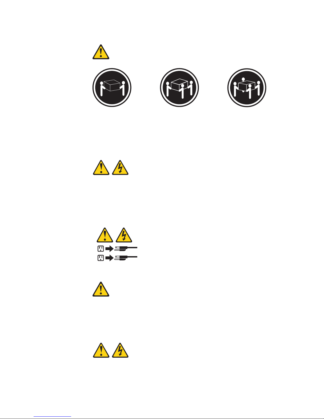
≥ 18 kg
≥ 32 kg
≥ 55 kg
Do
Statement 4:
(39.7 lb.)
(70.5 lb.)
(121.2 lb.)
CAUTION:
Use safe practices when lifting.
Statement 5:
CAUTION:
The power control button on the device and the power switch on the power
supply do not turn off the electrical current supplied to the device. The device
also might have more than one power cord. To remove all electrical current
from the device, ensure that all power cords are disconnected from the power
source.
2
1
Statement 6:
CAUTION:
not place any objects on top of a rack-mounted device unless that
rack-mounted device is intended for use as a shelf.
Statement 8:
Safety
ix
Page 12

a
x
CAUTION:
Never remove the cover on a power supply or any part that has the following
label attached.
Hazardous voltage, current, and energy levels are present inside any
component that has this label attached. There are no serviceable parts inside
these components. If you suspect a problem with one of these parts, contact
service technician.
WARNING: Handling the cord on this product or cords associated with accessories
sold with this product, will expose you to lead, a chemical known to the State of
California to cause cancer, and birth defects or other reproductive harm. Wash
hands after handling.
ADVERTENCIA:El contacto con el cable de este producto o con cables de
accesorios que se venden junto con este producto, pueden exponerle al plomo, un
elemento químico que en el estado de California de los Estados Unidos está
considerado como un causante de cancer y de defectos congénitos, además de
otros riesgos reproductivos. Lávese las manos después de usar el producto.
IBM xSeries 336 Type 8837: User’s Guide
Page 13

v
v
v
v
v
is
©
Chapter 1. Introducing the xSeries 336 Type 8837 server
The IBM
®
Eserver
™
xSeries
®
336 Type 8837 server is a 1-U-high
1
rack model
server for high-volume network transaction processing. This high-performance,
symmetric multiprocessing (SMP) server is ideally suited for networking
environments that require superior microprocessor performance, input/output (I/O)
flexibility, and high manageability.
Performance, ease of use, reliability, and expansion capabilities were key
considerations in the design of the server. These design features make it possible
for you to customize the system hardware to meet your needs today and provide
flexible expansion capabilities for the future.
The server comes with a limited warranty. For more information about the terms of
the warranty, see the warranty appendix in the Installation Guide.
The server contains IBM Enterprise X-Architecture
™
technologies, which help
increase performance and reliability. For more information, see “What your server
offers” on page 4 and “Reliability, availability, and serviceability” on page 5.
You can obtain up-to-date information about the server and other IBM server
products at http://www.ibm.com/eserver/xseries/.
For service or assistance information, see Appendix A, “Getting help and technical
assistance,” on page 43.
Related documentation
This User’s Guide provides general information about the server, including
information about features, how to configure the server, and how to get help. In
addition to this User’s Guide, the following documentation comes with the server:
Installation Guide
This printed document contains instructions for setting up the server and basic
instructions for installing some options.
Option Installation Guide
This document is in Portable Document Format (PDF) on the IBM xSeries
Documentation CD. It contains detailed instructions for installing, removing, and
connecting optional devices that the server supports.
Safety Information
This document is in PDF on the IBM xSeries Documentation CD. It contains
translated caution and danger statements. Each caution and danger statement
that appears in the documentation has a number that you can use to locate the
corresponding statement in your language in the Safety Information document.
Rack Installation Instructions
This printed document contains instructions for installing the server in a rack.
Hardware Maintenance Manual and Troubleshooting Guide
This document is in PDF on the IBM xSeries Documentation CD. It contains
information to help you solve problems yourself, and it contains information for
service technicians.
1. Racks are marked in vertical increments of 1.75 inches each. Each increment is referred to as a unit, or a “U”. A 1-U-high device
1.75 inches tall.
Copyright IBM Corp. 2004
1
Page 14

to
1. Go to
2. In
3. On
4. In
5.
v
v
v
v
to
v
2
Depending on your server model, additional documentation might be included on
the IBM xSeries Documentation CD.
The server might have features that are not described in the documentation that
you received with the server. The documentation might be updated occasionally to
include information about those features, or technical updates might be available to
provide additional information that is not included in the server documentation.
These updates are available from the IBM Web site. Complete the following steps
check for updated documentation and technical updates:
http://www.ibm.com/pc/support/.
the Learn section, click Online publications.
the “Online publications” page, in the Brand field, select Servers.
the Family field, select xSeries 336.
Click Continue.
Notices and statements used in this document
The caution and danger statements that appear in this document are also in the
multilingual Safety Information document, which is on the IBM xSeries
Documentation CD. Each statement is numbered for reference to the corresponding
statement in the Safety Information document.
The following notices and statements are used in this document:
Notes: These notices provide important tips, guidance, or advice.
Important: These notices provide information or advice that might help you avoid
inconvenient or problem situations.
Attention: These notices indicate potential damage to programs, devices, or
data. An attention notice is placed just before the instruction or situation in which
damage could occur.
Caution: These statements indicate situations that can be potentially hazardous
you. A caution statement is placed just before the description of a potentially
hazardous procedure step or situation.
Danger: These statements indicate situations that can be potentially lethal or
extremely hazardous to you. A danger statement is placed just before the
description of a potentially lethal or extremely hazardous procedure step or
situation.
IBM xSeries 336 Type 8837: User’s Guide
Page 15

v
v
v
v
v
v
v
GB
v
–
–
–
v
v
v
v
v
v
v
v
v
v
v
v
v
v
v
v
v
v
v
–
to
m
–
to
–
–
v
v
v
v
–
–
–
–
–
–
1.
2.
Features and specifications
The following information is a summary of the features and specifications of the
server. Depending on the server model, some features might not be available, or
some specifications might not apply.
Table 1. Features and specifications
Microprocessor:
Intel
™
®
Xeon
2.8 GHz or higher
depending on server model
Support for up to two
microprocessors with Intel
Hyper-Threading Technology and
EM64T (extended memory 64 bit
technology)
800 MHz front-side bus (FSB)
Memory:
Minimum: 512 MB
Maximum: 16 GB
Type: 2-way interleaved PC3200,
400 MHz, ECC DDR II SDRAM,
registered DIMMs only
Sizes: 256 MB, 512 MB, 1 GB, 2
(when available)
Expansion
bays:
Comes in 3 configurations:
Configuration 1 and 2
Two 3.5-inch hot-swap SCSI or
two 3.5-inch non-hot-swap
(simple swap) SATA hard disk
drives
One 9.5-mm high DVD-ROM
drive (optional)
Configuration 3
v
Four 2.5-inch hot-swap SCSI
hard disk drives
Expansion
slots:
One PCI-X 133 MHz or PCI Ex8,
full-length, full height (Note:
PCI-E x8 (PCI-E) requires an
optional riser card)
One PCI-X 100 MHz, half length,
low-profile
Power
supply:
585 watt hot-swap power supply
standard
Optional redundant 585 watt power
supply
Size:
Height: 43 mm (1.69 in.)
Depth: 686 mm (27.0 in.)
Width: 440 mm (17.32 in.)
Weight: approximately 15.6 kg
(34.5 lb) when fully configured or
12.7 kg (28 lb) minimum
Integrated
Baseboard management controller
(BMC)
One LSI Ultra320 SCSI controller
with RAID levels 1 and 1E
capability
Two Broadcom 10/100/1000
Ethernet controllers with Wake on
LAN
Format support
Three Universal Serial Bus (USB)
ports
One serial port
Keyboard port
Mouse port
Video port
Acoustical
Sound power, idling: 6.9 bel
maximum
Sound power, operating: 6.9 bel
maximum
Environment:
Air temperature:
v
Humidity:
functions:
®
feature and Alert Standard
noise emissions:
Server on: 10° to 35°C (50.0°
95.0°F); altitude: 0 to 2133
(6998.0 ft)
Server off: 10° to 43°C (50.0°
109.4°F); maximum altitude:
2133 m (6998.0 ft)
Server on: 8% to 80%
Server off: 8% to 80%
Heat output:
Approximate heat output in British
thermal units (Btu) per hour:
Minimum configuration: 587 Btu/hr
(172 watts)
Maximum configuration: 1878 Btu/hr
(550 watts)
Electrical
input:
Sine-wave input (50-60 Hz) required
Input voltage low range:
Minimum: 100 V ac
Maximum: 127 V ac
v
Input voltage high range:
Minimum: 200 V ac
Maximum: 240 V ac
v
Input kilovolt-amperes (kVA),
approximately:
Minimum: .172 kVA
Maximum: .550 kVA
Notes:
Power consumption and heat
output vary depending on the
number and type of optional
features installed and the
power-management optional
features in use.
These levels were measured in
controlled acoustical environments
according to the procedures
specified by the American National
Standards Institute (ANSI) S12.10
and ISO 7779 and are reported in
accordance with ISO 9296. Actual
sound-pressure levels in a given
location might exceed the average
values stated because of room
reflections and other nearby noise
sources. The declared sound-power
levels indicate an upper limit, below
which a large number of computers
will operate.
Chapter 1. Introducing the xSeries 336 Type 8837 server
3
Page 16

v
To
v
v
v
–
–
–
4
What your server offers
Your server uses the following features and technologies:
Device Driver and IBM Enhanced Diagnostics
start the Enhanced Diagnostics diagnostic programs, press F2 while the
server is starting.
Baseboard management controller
The baseboard management controller (BMC) is a service processor that
provides environmental monitoring for the server. If environmental conditions
exceed thresholds or if system components fail, the baseboard management
controller lights LEDs to help you diagnose the problem. Critical errors are also
included in the error log.
IBM Director
IBM Director is a workgroup-hardware-management tool that you can use to
centrally manage xSeries servers. For more information, see the IBM Director
documentation on the IBM Director CD.
IBM Enterprise X-Architecture technology
IBM X-Architecture technology combines proven, innovative IBM designs to make
your Intel-processor-based server powerful, scalable, and reliable. For more
information, go to
http://www.ibm.com/pc/us/eserver/xseries/xarchitecture/enterprise/index.html.
Active
The Active Memory feature improves the reliability of memory through memory
mirroring, and online-spare memory. Memory mirroring stores data in two
pairs of DIMMs simultaneously. Online-spare memory disables a failed pair of
DIMMs from the system configuration and activates a pair of online-spare
DIMMs. For more information, see the section about installing DIMMs in the
IBM xSeries 336 Type 8837 Installation Guide.
Large system-memory capacity
The memory bus supports up to 16 GB of system memory. The memory
controller supports error correcting code (ECC) for up to eight
industry-standard PC3200, 400 MHz, 1.8 V, 184-pin, registered,
double-data-rate (DDR), synchronous dynamic random access memory
(SDRAM) dual inline memory modules (DIMMs).
Memory ProteXion
The Memory ProteXion feature provides a function that is similar to a
hot-spare drive in a RAID array. It is based in the memory controller, and it
enables the server to sense when a chip on a DIMM has failed and to route
the data around the failed chip.
v
IBM ServerGuide
The ServerGuide Setup and Installation CD that comes with the server provides
programs to help you set up the server and install a 32-bit Windows
system. The ServerGuide program detects installed hardware options and
provides the correct configuration programs and device drivers. For more
information about the ServerGuide Setup and Installation CD, see “Using the
ServerGuide Setup and Installation CD” on page 21.
™
Memory
™
Setup and Installation CD
®
operating
IBM xSeries 336 Type 8837: User’s Guide
Page 17

v
v
v
v
v
v
v
is
v
v
Integrated network support
The server comes with an integrated Broadcom Gigabit Ethernet controller, which
supports connection to a 10-Mbps, 100-Mbps, or 1000-Mbps network. For more
information, see “Configuring the Gigabit Ethernet controller” on page 23.
Large data-storage capacity and hot-swap capability
The server supports up to four 2.5-inch or two 25.4-mm (1-inch) slim-high, 3.5
inch SCSI hot-swap hard disk drives in the hot-swap bays. With the hot-swap
feature, you can add, remove, or replace hard disk drives without turning off the
server.
This server also supports two 25.4-mm (1-inch) slim-high, 3.5-inch SATA simple
swap hard disk drives.
Light path diagnostics
Light path diagnostics provides LEDs to help you diagnose problems. For more
information, see the section about light path diagnostics in the Installation Guide.
Redundant connection
The addition of an optional network interface card (NIC) provides failover
capability to a redundant Ethernet connection. If a problem occurs with the
primary Ethernet connection, all Ethernet traffic that is associated with the
primary connection is automatically switched to the redundant NIC. If the
applicable device drivers are installed, this switching occurs without data loss and
without user intervention.
Redundant cooling and optional power capabilities
The redundant cooling of the fans in the server enables continued operation if
one of the fans fails. The server comes with one 585-watt hot-swap power
supply. You can order a second optional power supply, which provides redundant
power for many server configurations.
ServeRAID
™
support
The server supports ServeRAID adapters to create redundant array of
independent disks (RAID) configurations.
Symmetric multiprocessing (SMP)
The server supports up to two Intel microprocessors. If the server comes with
only one microprocessor, you can install an additional microprocessor to enhance
performance and provide SMP capability.
Systems-management capabilities
The server comes with a baseboard management controller (BMC) installed.
When used with the systems-management software that comes with the server,
you can manage the functions of the server locally and remotely. The BMC also
provides system monitoring, event recording, and dial-out alert capability.
The optional Remote Supervisor Adapter II SlimLine can be used to obtain
enhanced system management capabilities, above those of the embedded BMC.
The Remote Supervisor Adapter II SlimLine, when installed, has a dedicated
Ethernet connection at the rear of the server.
Reliability, availability, and serviceability
Three important computer design features are reliability, availability, and
serviceability (RAS). The RAS features help to ensure the integrity of the data that
stored in the server, the availability of the server when you need it, and the ease
with which you can diagnose and correct problems.
Your server has the following RAS features:
Automatic error retry and recovery
Chapter 1. Introducing the xSeries 336 Type 8837 server
5
Page 18

v
v
v
v
v
v
v
v
v
v
v
v
v
v
v
v
v
v
v
v
v
v
v
v
v
v
v
v
If a
6
v
Automatic restart after a power failure
Baseboard management controller (BMC) service processor
Backup basic input/output system (BIOS) switching under the control of the BMC
Built-in monitoring for fan, power, temperature, voltage, and power-supply
redundancy
Cable-presence detection on most connectors
Chipkill
™
memory protection
Error codes and messages
Error correcting code (ECC) L2 cache and system memory
Hot-swap hard disk drives
Information and light path diagnostics LED panels
Menu-driven setup, system configuration, and redundant array of independent
disks (RAID) configuration programs
Availability of microcode and diagnostic levels
Parity checking on the small computer system interface (SCSI) bus and PCI
buses
Power management: Compliance with Advanced Configuration and Power
Interface (ACPI)
Power-on self-test (POST)
Predictive Failure Analysis
®
(PFA) alerts
Redundant Ethernet capabilities with failover support
Hot-swap cooling fans with speed-sensing capability
Redundant hot-swap power supplies and redundant hot-swap fans (some
models)
Remind button to temporarily turn off the system-error LED
Remote system problem-determination support
Standby voltage for system-management features and monitoring
Startup (boot) from LAN through remote initial program load (RIPL) or dynamic
host configuration protocol/boot protocol (DHCP/BOOTP)
System auto-configuring from the configuration menu
System error logging (POST and BMC)
System-management monitoring through the Intra-Integrated Circuit (I2C) bus
Upgradeable POST, BIOS, diagnostics, BMC microcode, and read-only memory
(ROM) resident code, locally or over the LAN
Vital product data (VPD) on microprocessors, system board, power supplies,
SCSI (hot-swap-drive) backplane, and power backplane
Wake on LAN feature capability
Active Memory
™
Active
Memory is an IBM feature that improves the reliability of memory through
memory mirroring and the Memory ProteXion
Memory ProteXion
detected error is recoverable, the Memory ProteXion feature corrects the error
and rewrites the data to another memory location on the same DIMM. If there are
not sufficient undamaged memory locations that the data can be rewritten to, the
error is unrecoverable. Other conditions can also cause unrecoverable errors. If a
detected error is unrecoverable, light path diagnostics LEDs are lit to indicate the
failing DIMM.
You do not have to enable memory mirroring to use the Memory ProteXion feature.
IBM xSeries 336 Type 8837: User’s Guide
™
feature.
Page 19

To
v
v
v
v
v
v
v
v
v
v
v
Memory mirroring and sparing
Memory mirroring stores data in memory pair 1 and 2 and memory pair 3 and 4
simultaneously. To support memory mirroring, you must install identical dual inline
memory modules (DIMMs) in memory pair 1 and 2 and memory pair 3 and 4. For
more information, see the section about installing memory modules in the Option
Installation Guide on the IBM xSeries Documentation CD.
The server also supports memory sparing; however, the sparing feature is mutually
exclusive with mirroring. The sparing feature disables the failed memory from the
system configuration and activates a memory sparing pair of DIMMs to replace the
failed active DIMM pair.
Before you can enable the memory sparing feature, you must install one additional
pair of DIMMs. The memory sparing DIMM pair must be the same speed, type, and
the same size as or larger, than the active DIMM pair.
enable memory mirroring or sparing through the Configuration/Setup Utility
program, select Advanced Setup from the main menu, and select Memory
Configuration. For more information about using the Configuration/Setup Utility
program, see “Using the Configuration/Setup Utility program” on page 16.
IBM Director
With IBM Director, a network administrator can:
View the hardware configuration of remote systems, in detail
Monitor the usage and performance of critical components, such as
microprocessors, disks, and memory
Centrally manage individual or large groups of IBM and non-IBM Intel-based
servers, desktop computers, workstations, and mobile computers on a variety of
platforms
Director provides a comprehensive entry-level workgroup hardware manager. It
IBM
includes the following key features:
Advanced self-management capabilities for maximum system availability.
Multiple operating-system platform support, including Microsoft
®
Windows 2000
Server, Windows XP Professional, Red Hat Linux, SUSE LINUX, and Novell
NetWare. For a complete list of operating systems that support IBM Director, see
the IBM Director Compatibility Document. This document is in Portable Document
Format (PDF) at http://www.ibm.com/pc/ww/eserver/xseries/
systems_management/nfdir/agent.html. It is updated every 6 to 8 weeks.
Support for IBM and non-IBM servers, desktop computers, workstations, and
mobile computers.
Support for systems-management industry standards.
Integration into leading workgroup and enterprise systems-management
environments.
Ease of use, training, and setup.
Director also provides an extensible platform that supports advanced server
IBM
tools that are designed to reduce the total cost of managing and supporting
networked systems. By deploying IBM Director, you can achieve reductions in
ownership costs through:
Reduced downtime
Increased productivity of IT personnel and users
Chapter 1. Introducing the xSeries 336 Type 8837 server
7
Page 20
v
v
v
8
v
Reduced service and support costs
more information about IBM Director, see the IBM Director CD that comes with
For
your server, the IBM Director documentation on the CD, and the IBM xSeries
Systems Management Web page at
http://www-1.ibm.com/servers/eserver/xseries/systems_management/
xseries_sm.html, which presents an overview of IBM Systems Management and
IBM Director.
The UpdateXpress program
The UpdateXpress program is available for most xSeries servers and server
options. It detects supported and installed device drivers and firmware in your
server and installs available updates. You can download the UpdateXpress program
from the Web at no additional cost, or you can purchase it on a CD. To download
the program or purchase the CD, go to
http://www.ibm.com/pc/ww/eserver/xseries/serverguide/xpress.html.
Server controls, LEDs, and power
This section describes the controls and light-emitting diodes (LEDs) and how to turn
the server on and off.
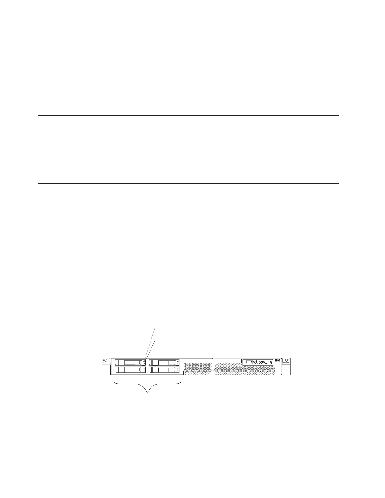
Front view
The following illustration shows the controls, LEDs, and connectors on the front of
the server. There are three different front views:
2.5-inch SCSI hot-swap hard disk drive
3.5-inch SCSI hot-swap hard disk drive
3.5-inch SATA non-hot-swap (simple swap) hard disk drive
Note:
The following illustration shows the front view of an IBM xSeries 336 server with a
2.5-inch SCSI hot-swap hard disk drive configuration.
Both 3.5-inch configurations support an optional DVD-ROM drive.
Hard disk drive activity LED
Hard disk drive status LED
SCSI ID 0
SCSI ID 2
Model #
Serial #
SCSI ID 1
4 x 2.5” Hard disk drives
IBM xSeries 336 Type 8837: User’s Guide
SCSI ID 3
Page 21
v
v
is
v
v
by a
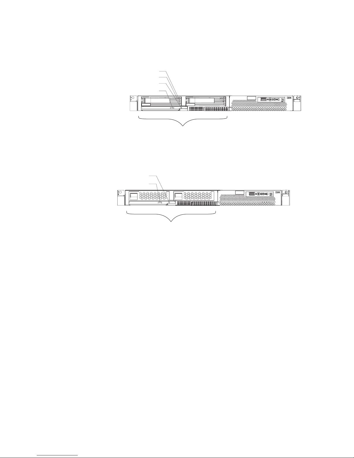
The following illustration shows the front view of an IBM xSeries 336 server with a
3.5-inch SCSI hot-swap hard disk drive configuration, with the optional DVD-ROM
drive.
Hard disk drive status LED
Hard disk drive activity LED
DVD-ROM activity LED
DVD-ROM eject button
Model #
Serial #
SCSI ID 0 SCSI ID 1
2 x 3.5” Hard disk drives
The following illustration shows the front view of an IBM xSeries 336 server with a
3.5-inch SATA simple swap hard disk drive configuration, with the optional
DVD-ROM drive.
DVD-ROM activity LED
DVD-ROM eject button
Model #
Serial #
SATA 0 SATA 1
2 x 3.5” Hard disk drives
The following information gives details about the previously mentioned controls,
LEDs, and connectors on the front of the server. The location of these items vary,
depending on the hardware configuration you have.
Hot-swap hard disk drive activity LED: This LED is used on SCSI hard disk
drives. Each hot-swap hard disk drive has an activity LED, and when this LED is
flashing, it indicates that the drive is in use.
Hot-swap hard disk drive status LED: This LED is used on SCSI hard disk
drives. When this LED is lit, it indicates that the drive has failed. If an optional
IBM ServeRAID controller is installed in the server, when this LED is flashing
slowly (one flash per second), it indicates that the drive is being rebuilt. When the
LED is flashing rapidly (three flashes per second), it indicates that the controller
identifying the drive.
DVD-eject button: Press this button to release a DVD or CD from the
DVD-ROM drive.
DVD-ROM drive activity LED: When this LED is lit, it indicates that the
DVD-ROM drive is in use.
Note: The DVD-ROM option is available only on the 3.5-inch drive configurations
Operator information panel
The operator information panel is on the front right side of the server. The following
illustration shows the LEDs on the front of the operator information panel, followed
description of each LED (from left to right):
(either SCSI or SATA hard disk drives).
Chapter 1. Introducing the xSeries 336 Type 8837 server
9
Page 22

v
v
A
v
v
v
in
v
v
10
System-error LED (amber)
Information LED (amber)
Location LED (blue)
Hard disk drive
activity LED (green)
Power control button
Power LED (green)
USB connector
v
USB connector: Connect a USB device to this connector.
Release latch
Power LED: When this green LED is lit and not flashing, it indicates that the
server is turned on. When this LED is flashing, it indicates that the server is
turned off and is still connected to an ac power source. When this LED is off, it
indicates that ac power is not present, or the power supply or the LED itself has
failed. A power LED is also on the rear of the server.
Note: If this LED is off, it does not mean that there is no electrical power in the
server. The LED might be burned out. To remove all electrical power from
the server, you must disconnect the power cord from the electrical outlet.
Power-control button: Press this button to turn the server on and off manually.
power-control-button shield comes with the server. You can install this
disk-shaped shield to prevent the server from being turned off accidentally.
Hard disk drive activity LED: When this green LED is lit, it indicates that one of
the hard disk drives is in use.
Note: Hard disk drive activity for the SCSI drives is shown in two places, on the
hard disk drive itself and also on the hard disk drive activity LED on the
operator information panel.
There is no hard disk drive activity LED for the SATA drive. The only place
the SATA drive indicates hard disk drive activity is on the operator
information panel.
Location LED: Use this blue LED to visually locate the server if it is in a location
with numerous other servers. You can use IBM Director to light this LED
remotely. This LED is controlled by the BMC.
Information LED: When this amber LED is lit, it indicates that a non-critical
event has occurred. Check the error log for additional information. See the note
the “Light Path diagnostics panel” section, in the Option Installation Guide, for
more information about error logs.
System-error LED: When this amber LED is lit, it indicates that a system error
has occurred. A System-error LED is also on the rear of the server. An LED on
the Light Path diagnostics panel on the system board is also lit to help isolate the
error. This LED is controlled by the BMC.
Release Latch: Press the release latch, on the right side of the operator
information panel, to slide out the operator information panel and view the Light
Path LEDs and buttons.
Light Path LEDs and buttons: The Light Path LEDs and buttons are on top of the
operator information panel. The following illustration shows the LEDs on the Light
IBM xSeries 336 Type 8837: User’s Guide
Page 23

v
By
v
v
An
S
SP
Path Diagnostics panel, followed by a description of the buttons and each LED.
Remind button: This button places the system-error LED on the front panel into
remind mode. In remind mode, the system error LED flashes rapidly until the
problem is corrected, the system is restarted, or a new problem occurs.
placing the system error LED indicator in remind mode, you acknowledge that
you are aware of the last failure but will not take immediate action to correct the
problem. The remind function is handled by the BMC.
Reset button: Press this button to reset the server and run the power-on
self-test (POST). You might have to use a pen or the end of a straightened paper
clip to press the button. The reset button is to the right of the remind button and
just above the small circle with the R inside.
Light Path diagnostic LEDs: You can slide out the operator information panel
and drop it down for easy viewing without opening the top server cover. The
LEDs are on the top of the operator information panel.
The following table lists the LEDs and the problems that they indicate.
LED
None
Error
error that is not reflected in the Light Path diagnostics panel
OVER SPEC The power supplies are using more power than their maximum rating
allows
PS1
PS2
CPU
VRM
CNFG
MEM
NMI
ERR
Power supply 1
Power supply 2
Microprocessor error
Voltage Regulator Module (VRM)
Configuration error, check the microprocessor and memory configuration
Memory
Nonmaskable interrupt
Soft error
Service processor
DASD
FAN
TEMP
BRD
PCI-A
PCI-B
PCI-C
Hard disk drive
Fan (TEMP LED might also be lit)
System temperature
Error with the system board, or a battery fault
PCI-A bus
PCI-B bus
PCI-C bus
Chapter 1. Introducing the xSeries 336 Type 8837 server
11
Page 24

v
v
v
v AC
v DC
v
v
v
v
v
v
v
v
v
v
12
Rear view
The following illustration shows the connectors and LEDs on the rear of the server.
Power supply 1Power supply 2
PCI slot 1 PCI slot 2
AC and DC LEDs
3 rear LEDs (Power, Location, System-error)
Video
Serial
USBs
Keyboard
Mouse
Ethernet LEDs
Dual GB Ethernet
Remote Supervisor
Adapter II SlimLine
Ethernet LEDs
Remote Supervisor Adapter II EthernetSlimLine
Ethernet LEDs
PCI slot 1: This slot allows insertion of a low profile adapter.
PCI slot 2: This slot allows insertion of any PCI-X or PCI-E type adapter.
Power supply 2: Provides dc power to the server, is a redundant backup power
supply.
LED: This LED is to the left of the power-cord connector and is the top LED.
This LED indicates that the server has an ac power connection.
LED: This LED is to the left of the power-cord connector and is the bottom
LED. This LED indicates that the power supply is providing dc power to the
server.
Power supply 1: Provides dc power to the server, is the primary power supply.
Power LED: This is the top LED and it indicates that ac power is present on the
server.
Location LED: This middle (blue) LED assists you in visually locating the server
when it is among other servers
System-error LED: This is the bottom LED and it indicates that a system error
occurred.
Video connector: Connect a monitor to this connector.
Serial connector: Connect a 9-pin serial device to this connector.
USB connectors: Connect a USB device to these connectors.
Keyboard connector: Connect a PS/2
®
keyboard to this connector.
Mouse connector: Connect a mouse or other PS/2 device to this connector.
Ethernet LEDs: There are a set of LEDs for each Ethernet connector. The top
LED is the Ethernet link LED. When it is lit, it indicates that there is an active
connection on the Ethernet port.
The bottom LED is the Ethernet activity LED. When it flashes, it indicates that
data is being transmitted or received between the server and a network device.
The flashing frequency is proportional to the amount of traffic on the network link.
IBM xSeries 336 Type 8837: User’s Guide
Page 25

an
v
v
II
v If a
v If
v If
v
Dual GB Ethernet connectors: Use these connectors to connect the server to
Ethernet network.
Remote Supervisor Adapter II SlimLine Ethernet connector: Use this
connector to connect the server to a network for system-management information
control. This Ethernet connector is active only when you have installed the
Remote Supervisor Adapter II SlimLine option.
Remote Supervisor Adapter II SlimLine Ethernet LEDs: These LEDs are
located on the Ethernet connector and are at the top left and top right positions.
The top left LED is the Ethernet link LED for the Remote Supervisor Adapter II
SlimLine. When this LED is lit, it indicates that there is an active connection on
the Ethernet port.
The top right LED is the Ethernet activity LED for the Remote Supervisor Adapter
SlimLine. When this LED flashes, it indicates that data is being transmitted or
received between the server and a network device. The flashing frequency is
proportional to the amount of traffic on the network link.
Server power features
When the server is connected to an ac power source but is not turned on, the
operating system does not run, and all core logic except for the BMC is shut down;
however, the server can respond to requests from the service processor, such as a
remote request to turn on the server. The power-on LED flashes to indicate that the
server is connected to ac power but is not turned on.
Turning on the server
When you connect the server to ac power, the power supply fans turn on
immediately. Pressing the power-control button lets you turn on the server and start
the operating system.
The server can also be turned on in any of the following ways:
power failure occurs while the server is turned on, the server will restart
automatically when power is restored.
your operating system supports the system-management software for the
Remote Supervisor Adapter II SlimLine option, the system-management software
can turn on the server.
your operating system supports the Wake on LAN feature, the Wake on LAN
feature can turn on the server.
Turning off the server
When you turn off the server and leave it connected to ac power, the power supply
fans continue to run and the server can respond to requests from the service
processor, such as a remote request to turn on the server. To remove all power
from the server, you must disconnect it from the power source.
Some operating systems require an orderly shutdown before you turn off the server.
See your operating-system documentation for information about shutting down the
operating system.
Statement 5:
Chapter 1. Introducing the xSeries 336 Type 8837 server
13
Page 26

v
v
v If
v If
v If
v
v
14
CAUTION:
The power control button on the device and the power switch on the power
supply do not turn off the electrical current supplied to the device. The device
also might have more than one power cord. To remove all electrical current
from the device, ensure that all power cords are disconnected from the power
source.
2
1
The server can be turned off in any of the following ways:
You can turn off the server from the operating system, if your operating system
supports this feature. After an orderly shutdown of the operating system, the
server will turn off automatically.
You can press the power-control button to start an orderly shutdown of the
operating system and turn off the server, if your operating system supports this
feature.
the operating system stops functioning, you can press and hold the
power-control button for more than 4 seconds to turn off the server.
you installed the Remote Supervisor Adapter II SlimLine option in the server,
the server can be turned off from the Remote Supervisor Adapter II SlimLine user
interface.
the Wake on LAN feature turned on the server, the Wake on LAN feature can
turn off the server.
The baseboard management controller can turn off the server as an automatic
response to a critical system failure.
You can turn off the server through a request from the service processor.
IBM xSeries 336 Type 8837: User’s Guide
Page 27

v
v
to
v
v
v
–
–
v
©
Chapter 2. Configuring the server
The following configuration programs and capabilities come with your server:
Configuration/Setup Utility program
The Configuration/Setup Utility program is part of the basic input/output system
(BIOS) code in the server. Use it to change interrupt request (IRQ) settings,
change the startup-device sequence, set the date and time, and set passwords.
For information about using this utility program, see “Using the
Configuration/Setup Utility program” on page 16.
IBM ServerGuide Setup and Installation CD
The ServerGuide program provides software-setup tools and installation tools
that are designed for the server. Use this CD during the installation of the server
configure basic hardware features, such as an integrated SCSI controller with
RAID capabilities, and to simplify the installation of your operating system. For
information about using this CD, see “Using the ServerGuide Setup and
Installation CD” on page 21.
Ethernet controller configuration
For information about configuring the Ethernet controller, see “Configuring the
Gigabit Ethernet controller” on page 23.
Baseboard management controller
Use the baseboard management controller utility programs to configure the
baseboard management controller. The utilities also provide the capability to
update the firmware and sensor data record/field replacable unit (SDR/FRU) data
and to configure a network for remote server management. For information about
using the baseboard management controller utility programs, see “Using the
baseboard management controller” on page 24.
RAID configuration programs
LSI Logic Configuration Utility program
Use the LSI Logic Configuration Utility to configure the integrated SCSI
controller with RAID capabilities and the devices that are attached to it. For
information about using this utility program, see “Using the LSI Logic setup
utility program” on page 37.
ServeRAID Manager
ServeRAID Manager is available as a stand-alone program and as an IBM
Director extension. If a ServeRAID adapter is installed in the server or if you
are using the RAID capabilities of the SCSI controller, use ServeRAID
Manager to define and configure your disk-array subsystem before you install
the operating system. For information about using this program, see “Using
ServeRAID Manager” on page 38.
v
Remote Supervisor Adapter II SlimLine configuration
For information about setting up and cabling the Remote Supervisor Adapter II
SlimLine, see “Setting up the Remote Supervisor Adapter II SlimLine” on page
39.
Boot Menu program
The Boot Menu program is part of the BIOS code in the server. Use it to
temporarily assign a device to be first in the startup sequence, overriding the
startup sequence that is set in the Configuration/Setup Utility program.
Copyright IBM Corp. 2004
15
Page 28

v
v
v
v
v
v
v
v
v
v
1.
2.
3.
on
v
v
of
v
16
Using the Configuration/Setup Utility program
Use the Configuration/Setup Utility program to:
View configuration information
View and change assignments for devices and I/O ports
Set the date and time
Set the startup characteristics of the server and the order of startup devices
Set and change settings for advanced hardware features
View, set, and change settings for power-management features
View and clear error logs
Change interrupt request (IRQ) settings
Enable USB keyboard and mouse support
Resolve configuration conflicts
Starting the Configuration/Setup Utility program
Complete the following steps to start the Configuration/Setup Utility program:
Turn on the server.
When the prompt Press F1 for Configuration/Setup appears, press F1. If you
have set both a power-on password and an administrator password, you must
type the administrator password to access the full Configuration/Setup Utility
menu. If you do not type the administrator password, a limited
Configuration/Setup Utility menu is available.
Select settings to view or change.
Configuration/Setup Utility menu choices
The following choices are on the Configuration/Setup Utility main menu. Depending
the version of the BIOS code in the server, some menu choices might differ
slightly from these descriptions.
System Summary
Select this choice to view configuration information, including the type, speed,
and cache sizes of the microprocessors and the amount of installed memory.
When you make configuration changes through other options in the
Configuration/Setup Utility program, the changes are reflected in the system
summary; you cannot change settings directly in the system summary.
This choice is on the full and limited Configuration/Setup Utility menu.
System Information
Select this choice to view information about your server. When you make
changes through other options in the Configuration/Setup Utility program, some
those changes are reflected in the system information; you cannot change
settings directly in the system information.
When you select the system information option, you are presented one choice,
product data. Select product data to view the machine type and model of your
server, the serial number, and the revision level or issue date of the BIOS and
diagnostics code stored in electrically erasable programmable ROM (EEPROM).
Devices and I/O Ports
Select this choice to view or change assignments for devices and input/output
(I/O) ports.
Select this choice to enable or disable integrated SCSI and Ethernet controllers
and all standard ports (such as serial). Enable is the default setting for all
IBM xSeries 336 Type 8837: User’s Guide
Page 29

v
v
to
–
–
no
If
controllers. If you disable a device, it cannot be configured, and the operating
system will not be able to detect it (this is equivalent to disconnecting the
device). If you disable the integrated SCSI controller and no SCSI adapter is
installed, the server will have no SCSI capability. If you disable the integrated
Ethernet controller and no Ethernet adapter is installed, the server will have no
Ethernet capability. If you disable the integrated USB controller, the server will
have no USB capability; to maintain USB capability, make sure that Enabled is
selected for the USB Host Controller and USB BIOS Legacy Support options.
This choice is on the full Configuration/Setup Utility menu only.
Date and Time
Select this choice to set the date and time in the server, in 24-hour format
(hour:minute:second).
This choice is on the full Configuration/Setup Utility menu only.
System Security
Select this choice to set passwords. See “Passwords” on page 19 for more
information about passwords. You can also enable the chassis-intrusion detector
alert you each time the server cover is removed.
This choice is on the full Configuration/Setup Utility menu only.
Power-on Password
Select this choice to set or change a power-on password. See “Power-on
password” on page 19 for more information.
Administrator Password
Attention: If you set an administrator password and then forget it, there is
way to change, override, or remove it. You must replace the system board.
Select this choice to set or change an administrator password. An
administrator password is intended to be used by a system administrator; it
limits access to the full Configuration/Setup Utility menu. If an administrator
password is set, the full Configuration/Setup Utility menu is available only if
you type the administrator password at the password prompt. See
“Administrator password” on page 20 for more information.
Note: The Administrator Password choice is on the Configuration/Setup
Utility menu only if you installed the IBM Remote Supervisor Adapter II
Slimline option.
v
Start Options
Select this choice to view or change the start options. Changes in the start
options take effect when you restart the server.
The startup sequence specifies the order in which the server checks devices to
find a boot record. The server starts from the first boot record that it finds. If your
server has the Wake on LAN hardware and software and the operating system
supports the Wake on LAN functions, you can specify a startup sequence for the
Wake on LAN functions. You can also specify whether the integrated SCSI
controller or a PCI SCSI adapter has boot precedence.
You can set keyboard operating characteristics, such as the keyboard speed, and
you can specify whether the server starts with the keyboard number lock on or
off. You can enable the server to run without a diskette drive, monitor, or
keyboard.
you enable the boot fail count, the BIOS default settings will be restored after
three consecutive failures to find a boot record.
You can enable a virus-detection test that checks for changes in the boot record
when the server starts.
Chapter 2. Configuring the server
17
Page 30

v
–
–
-
- In
-
–
–
-
-
v
v
If
18
This choice is on the full Configuration/Setup Utility menu only.
Advanced Setup
Select this choice to change settings for advanced hardware features.
Important: The server might malfunction if these options are incorrectly
configured. Follow the instructions on the screen carefully.
This choice is on the full Configuration/Setup Utility menu only.
System Partition Visibility
Select this choice to specify whether the System Partition is to be visible or
hidden.
Memory Settings
Select this choice to manually enable a pair of memory connectors. If a
memory error is detected during POST or memory configuration, the server
automatically disables the failing pair of memory connectors and continues
operating with reduced memory. After the problem is corrected, you must
manually enable the memory connectors. Use the arrow keys to highlight the
pair of memory connectors that you want to enable, and use the arrow keys to
select Enable.
You can select any of the following memory configurations:
The flat (default) configuration uses memory without any redundancy.
mirroring mode, memory pairs act as a RAID level 1 memory array. This
option reduces the amount of memory usable by the system by half.
Sparing mode sets aside memory to dynamically replace a section of failing
memory during system operation. This mode also reduces the amount of
memory available to the system. The mirroring and sparing configuration
requires that the memory be placed in multiple memory sockets.
CPU Options
–
Select this choice to disable the microprocessor cache or to set it to use the
write-back or write-through method. Write-back caching generally provides
better system performance.
Hyper-Threading technology enables a server with one microprocessor to
operate as if it were two microprocessors. Utilizing the CPU option allows
better system performance, and will appear to the Operating System that
twice the number of microprocessors are present.
You can enable the Prefetch Queue option from the CPU options menu. The
Prefetch Queue option along with 64-bit addressing, in EM64T, can boost the
software performance of the server.
PCI Bus Control
Select this choice to view and set interrupts for PCI devices and to configure
the master-latency-timer (MLT) value for the server.
Baseboard management controller Settings
This option provides you with the following choices:
View the BMC firmware version
Enable and set timeout values for the following items:
BMC post watchdog
BMC OS loader watchdog
Enable the Reboot on NMI option
-
you enable this option, the server will automatically restart 60 seconds
after the BMC issues a nonmaskable interrupt (NMI) to the server. If you
IBM xSeries 336 Type 8837: User’s Guide
Page 31

-
IP
-
–
–
If an
If
An
If
A
If a
disable this option, the server will not restart. Reboot on NMI happens
when a severe error occurs. Enable is the default setting.
Specify the way the server obtains an IP address.
Use the BMC network configuration option to either set the IP address
statically yourself or to enable DHCP control, which lets the server get the
address dynamically from the DHCP server.
View and clear the entries in the BMC system event log.
Event/Error Logs
v
Select this choice to view or clear error logs.
POST Error Log
Select this choice to view the three most recent error codes and messages
that were generated during POST. Select Clear error logs to clear the POST
error log.
System Event/Error Log
IBM Remote Supervisor Adapter II SlimLine option is installed, the full
text of the error messages is displayed. Run the diagnostic program to get
more information about error codes that occur. See the Hardware
Maintenance Manual and Troubleshooting Guide on the IBM xSeries
Documentation CD for instructions. Select Clear error logs to clear the
System Event/Error log.
Passwords
From the System Security choice, you can set, change, and delete a power-on
password and an administrator password. The System Security choice is on the
full Configuration/Setup menu only.
you set only a power-on password, you must type the power-on password to
complete the system startup and to have access to the full Configuration/Setup
Utility menu.
administrator password is intended to be used by a system administrator; it
limits access to the full Configuration/Setup Utility menu. If you set only an
administrator password, you do not have to type a password to complete the
system startup, but you must type the administrator password to access the
Configuration/Setup Utility menu.
you set a power-on password for a user and an administrator password for a
system administrator, you can type either password to complete the system startup.
system administrator who types the administrator password has access to the full
Configuration/Setup Utility menu; the system administrator can give the user
authority to set, change, and delete the power-on password. A user who types the
power-on password has access to only the limited Configuration/Setup Utility menu;
the user can set, change, and delete the power-on password, if the system
administrator has given the user that authority.
Power-on password
power-on password is set, when you turn on the server, the system startup will
not be completed until you type the power-on password. You can use any
combination of up to seven characters (A–Z, a–z, and 0–9) for the password.
When a power-on password is set, you can enable the Unattended Start mode, in
which the keyboard and mouse remain locked but the operating system can start.
You can unlock the keyboard and mouse by typing the power-on password.
Chapter 2. Configuring the server
19
Page 32

v If an
v
v
If an
up to
to
v
20
If you forget the power-on password, you can regain access to the server in any of
the following ways:
administrator password is set, type the administrator password at the
password prompt. Start the Configuration/Setup Utility program and reset the
power-on password.
Remove the server battery and then reinstall it. See the Option Installation Guide
for instructions for removing the battery.
Change the position of the power-on password override jumper (J22 on the
system board) to bypass the power-on password check (see the following
illustration).
BIOS boot backup (J21)
Password reset (J22)
Force update BMC (J48)
Attention: Before changing any switch settings or moving any jumpers, turn off
the server; then, disconnect all power cords and external cables. See the safety
information beginning on page v. Do not change settings or move jumpers on
any system-board switch or jumper blocks that are not shown in this document.
While the server is turned off, move the jumper on J22 to pin positions 2 and 3
(see previous illustration for jumper location). You can then start the
Configuration/Setup Utility program and reset the power-on password. You do not
have to return the jumper to the previous position.
The power-on password override jumper does not affect the administrator
password.
Administrator password
administrator password is set, you must type the administrator password for
access to the full Configuration/Setup Utility menu. You can use any combination of
seven characters (A–Z, a–z, and 0–9) for the password.
Note: The Administrator Password choice is on the Configuration/Setup Utility
menu only if you installed the IBM Remote Supervisor Adapter II Slimline
option.
Attention: If you set an administrator password and then forget it, there is no way
change, override, or remove it. You must replace the system board.
Using the Boot menu
The Boot Menu program is a built-in, menu-driven configuration utility program that
you can use to temporarily redefine the first startup device without changing
settings in the Configuration/Setup utility program.
Complete the following steps to use the Boot Menu program:
Turn off the server.
IBM xSeries 336 Type 8837: User’s Guide
Page 33

v
v
–
–
–
–
–
To
v
Restart the server.
Press F12, the Select Boot Device menu is displayed.
Note: If you installed a bootable USB mass storage device, a submenu item
USB Key/Disk is displayed.
Select a bootable item from the menu, which brings up a submenu with the
following options:
Yes: anytime this device is installed, the system will attempt to boot it
This boot only: this device will be boot attempted this boot only
Next boot: this device will be boot attempted this boot and the next boot
Next 2 boots: this device will be boot attempted this boot and the next 2 boots
Next 3 boots: this device will be boot attempted this boot and the next 3 boots
After selecting an option, select the Exit and continue booting option.
v
Note: You can press ESC at anytime to cancel the selection of the device and to
return to the previous menu.
next time the server starts, it returns to the startup sequence that is set in the
The
Configuration/Setup utility program.
Starting the backup BIOS
The system board contains a backup copy area for the BIOS code. This is a
secondary copy of BIOS that you update only during the process of flashing the
system. If the primary copy of the BIOS code becomes damaged, use this backup
copy.
BIOS boot backup (J21)
Password reset (J22)
Force update BMC (J48)
force the server to start from the backup copy, turn off the server; then, place the
J21 jumper in the backup position (pins 2 and 3).
Use the backup of the BIOS code until the primary copy is restored. After the
primary copy is restored, turn off the server; then, move the J21 jumper back to the
primary position.
Using the ServerGuide Setup and Installation CD
The ServerGuide Setup and Installation CD includes an easy-to-use setup and
installation program that is designed for your IBM server. The ServerGuide program
detects the server model and hardware options that are installed and uses that
information during setup to configure the hardware. The ServerGuide program
simplifies operating-system installations by providing updated device drivers and, in
some cases, installing them automatically.
Chapter 2. Configuring the server
21
Page 34

If a
To
at
v An
v
v
v
v
v
v
v
v
v
v
On a
22
Note: The ServerGuide program works only with 32-bit Windows operating
systems.
later version of the ServerGuide program is available, you can download a free
image of the ServerGuide Setup and Installation CD, or you can purchase the CD.
download the image, go to the IBM ServerGuide Web page at
http://www.ibm.com/pc/qtechinfo/MIGR-4ZKPPT.html. To purchase the latest
ServerGuide Setup and Installation CD, go to the ServerGuide fulfillment Web site
http://www.ibm.com/pc/coupon/.
The ServerGuide program has the following features to make setup easier:
easy-to-use interface
Diskette-free setup, and configuration programs that are based on detected
hardware
ServeRAID Manager program, which configures your ServeRAID adapter or
integrated SCSI controller with RAID capabilities
Device drivers that are provided for your server model and detected hardware
Operating-system partition size and file-system type that are selectable during
setup
ServerGuide features
Features and functions can vary slightly with different versions of the ServerGuide
program. To learn more about the version that you have, start the ServerGuide
Setup and Installation CD and view the online overview. Not all features are
supported on all server models.
The ServerGuide program requires a supported IBM server with an enabled
startable (bootable) CD-ROM drive. In addition to the ServerGuide Setup and
Installation CD, you must have your operating-system CD to install your operating
system.
The ServerGuide program has the following features:
Sets system date and time
Detects the SCSI RAID adapter, controller, or integrated SCSI controller with
RAID capabilities and runs the SCSI RAID configuration program (with LSI chip
sets for ServeRAID adapters only)
Checks the microcode (firmware) levels of a ServeRAID adapter and determines
whether a later level is available from the CD
Detects installed hardware options and provides updated device drivers for most
adapters and devices
Provides diskette-free installation for supported Windows operating systems
Includes an online readme file with links to tips for your hardware and
operating-system installation
Setup and configuration overview
When you use the ServerGuide Setup and Installation CD, you do not need setup
diskettes. You can use the CD to configure any supported IBM server model. The
setup program provides a list of tasks that are required to set up your server model.
server with a ServeRAID adapter or integrated SCSI controller with RAID
capabilities, you can run the SCSI RAID configuration program to create logical
drives.
Note: Features and functions can vary slightly with different versions of the
ServerGuide program.
IBM xSeries 336 Type 8837: User’s Guide
Page 35

v
v
v
v
v
1.
2.
CD
3.
4.
If
to
1. Go to
2. In
3. On
4. In
5.
6. In
7.
of
When you start the ServerGuide Setup and Installation CD, the program prompts
you to complete the following tasks:
Select your language.
Select your keyboard layout and country.
View the overview to learn about ServerGuide features.
View the readme file to review installation tips for your operating system and
adapter.
Start the operating-system installation. You will need your operating-system CD.
Typical operating-system installation
You can use the ServerGuide program to shorten the installation time. The
ServerGuide program provides the device drivers that are required for your
hardware and for the operating system that you are installing. This section
describes a typical ServerGuide operating-system installation.
Note: Features and functions can vary slightly with different versions of the
ServerGuide program.
After you have completed the setup process, the operating-system installation
program starts. (You will need your operating-system CD to complete the
installation.)
The ServerGuide program stores information about the server model, BMC,
hard disk drive controllers, and network adapters. Then, the program checks the
for newer device drivers. This information is stored and then passed to the
operating-system installation program.
The ServerGuide program presents operating-system partition options that are
based on your operating-system selection and the installed hard disk drives.
The ServerGuide program prompts you to insert your operating-system CD and
restart the server. At this point, the installation program for the operating system
takes control to complete the installation.
Installing your operating system without ServerGuide
you have already configured the server hardware and you decide not to use the
ServerGuide program to install your operating system, complete the following steps
download the latest operating-system installation instructions from the IBM
Support Web page:
http://www.ibm.com/pc/support/.
the Download section, click Downloads & drivers.
the “Downloads and drivers” page, in the Brand field, select Servers.
the Family field, select xSeries 336.
Click Continue.
the View by document type field, select OS installation.
Select the instructions for your operating system.
Configuring the Gigabit Ethernet controller
The Ethernet controllers are integrated on the system board. They provide an
interface for connecting to a 10-Mbps, 100-Mbps, or 1-Gbps network and provide
full-duplex (FDX) capability, which enables simultaneous transmission and reception
data on the network. If the Ethernet ports in the server support auto-negotiation,
the controllers detect the data-transfer rate (10BASE-T, 100BASE-TX, or
Chapter 2. Configuring the server
23
Page 36

v
as a
v
To
v To
v To
v To
1.
a.
b.
24
1000BASE-T) and duplex mode (full-duplex or half-duplex) of the network and
automatically operate at that rate and mode.
You do not have to set any jumpers or configure the controllers. However, you must
install a device driver to enable the operating system to address the controllers. For
device drivers and information about configuring the Ethernet controllers, see the
Broadcom NetXtreme Gigabit Ethernet Software CD that comes with the server. For
updated information about configuring the controllers, go to
http://www.ibm.com/pc/support/.
Using the baseboard management controller
The baseboard management controller provides environmental monitoring for the
server. If environmental conditions exceed thresholds or if system components fail,
the baseboard management controller lights LEDs to help you diagnose the
problem and also records the error in the System Event/Error log.
The baseboard management controller also provides the following remote server
management capabilities through the OSA SMBridge management utility program:
Command-line interface (IPMI Shell)
The command-line interface provides direct access to server management
functions through the IPMI 1.5 protocol. Use the command-line interface to issue
commands to control the server power, view system information, and identify the
server. You can also save one or more commands as a text file and run the file
script.
Serial over LAN
Establish a Serial over LAN (SOL) connection to manage servers from a remote
location. You can remotely view and change the BIOS settings, restart the server,
identify the server, and perform other management functions. Any standard
Telenet client application can access the SOL connection.
Enabling and configuring SOL using the OSA SMBridge management
utility program
enable and configure the server for SOL by using the OSA SMBridge
management utility program, you must update and configure the BIOS code and
enable the operating system for an SOL connection.
Note: In an SOL session, use the following commands instead of function keys:
start the Configuration/Setup Utility program when the prompt Press F1
for Configuration/Setup appears, press Esc, Shift+o, then Shift+p.
start the diagnostic programs, when the prompt F2 for Diagnostics
appears, press Esc, Shift+o, then Shift+q.
recover BIOS, when the prompt F3 for BIOS Recovery appears, press
Esc, Shift+o, then Shift+r.
BIOS update and configuration
Complete the following steps to update and configure the BIOS code to enable
SOL:
Update the BIOS code:
Download the latest version of the BIOS code from
http://www.ibm.com/pc/support/.
Update the BIOS code, following the instructions that come with the update
file that you downloaded.
IBM xSeries 336 Type 8837: User’s Guide
Page 37

a.
b.
v
v
v
v
v
v
v
v
v
v
v
v
e.
v
v
g.
h.
i.
j.
2.
Configure the BIOS settings:
Restart the server and press F1 when prompted to start the
Configuration/Setup Utility program.
Select Devices and I/O Ports; then, make sure that the values are set as
follows:
Serial Port A: Auto-configure
Serial Port B: Auto-configure
Select Remote Console Redirection; then, make sure that the values are
c.
set as follows:
Remote Console Active: Enabled
Remote Console COM Port: COM 1
Remote Console Baud Rate: 19200
Remote Console Data Bits: 8
Remote Console Parity: None
Remote Console Stop Bits: 1
Remote Console Text Emulation: ANSI
Remote Console Keyboard Emulation: ANSI
Remote Console Active After Boot: Enabled
Remote Console Flow Control: Hardware
Press Esc twice to exit the Remote Console Redirection and Devices and
d.
I/O Ports sections of the Configuration/Setup Utility program.
Note: Do not use Planar Ethernet 1 for PXE/DHCP booting or installation.
Select Start Options; then, set Planar Ethernet PXE/DHCP to one of the
following settings:
Disabled
Planar Ethernet 2. If you set Planar Ethernet PXE/DHCP to Planar
Ethernet 2, you must also set Run PXE only on selected Planar NIC to
Enabled.
f.
Press Esc to exit the Start Options section of the Configuration/Setup Utility
program.
Select Save Settings; then, press Enter.
Press Enter to confirm.
Select Exit Setup; then, press Enter.
Make sure that Yes, exit the Setup Utility is selected; then, press Enter.
Linux configuration
For SOL operation on the server, you must configure the Linux operating system to
expose the Linux initialization (booting) process. This enables users to log in to the
Linux console through an SOL session and directs Linux output to the serial
console. See the documentation for your specific Linux operating-system type for
information and instructions.
Use one of the following procedures to enable SOL sessions for your Linux
operating system. You must be logged in as a root user to perform these
procedures.
Red Hat Enterprise Linux ES 2.1 configuration:
Chapter 2. Configuring the server
25
Page 38

ES
1.
2.
If
1.
a.
b.
c.
of
d.
#
e.
f.
g.
#
26
Note: This procedure is based on a default installation of Red Hat Enterprise Linux
2.1. The file names, structures, and commands might be different for
other versions of Red Hat Linux.
Complete the following steps to configure the general Linux parameters for SOL
operation when using the Red Hat Enterprise Linux ES 2.1 operating system.
Note: Hardware flow control prevents character loss during communication over a
serial connection. You must enable it when using a Linux operating system.
Add the following line to the end of the # Run gettys in standard runlevels
section of the /etc/inittab file. This enables hardware flow control and enables
users to log in through the SOL console.
7:2345:respawn:/sbin/agetty -h ttyS0 19200 vt102
Add the following line at the bottom of the /etc/securetty file to enable a user to
log in as the root user through the SOL console:
ttyS1
LILO configuration:
you are using LILO, complete the following steps:
Complete the following steps to modify the /etc/lilo.conf file:
Add the following text to the end of the first default=linux line
-Monitor
Comment out the map=/boot/map line by adding a # at the beginning of this
line.
Comment out the message=/boot/message line by adding a # at the beginning
this line.
Add the following line before the first image= line:
This will allow you to only Monitor the OS boot via SOL
Add the following text to the end of the first label=linux line:
-Monitor
Add the following line to the first image= section. This enables SOL.
append="console=ttyS0,19200n8 console=tty1"
Add the following lines between the two image= sections:
This will allow you to Interact with the OS boot via SOL
image=/boot/vmlinuz-2.4.9-e.12smp
label=linux-Interact
initrd=/boot/initrd-2.4.9-e.12smp.img
read-only
root=/dev/hda6
append="console=tty1 console=ttyS0,19200n8 "
The following examples show the original content of the /etc/lilo.conf file and the
content of this file after modification.
IBM xSeries 336 Type 8837: User’s Guide
Page 39

Original /etc/lilo.conf contents
prompt
timeout=50
default=linux
boot=/dev/hda
map=/boot/map
install=/boot/boot.b
message=/boot/message
linear
image=/boot/vmlinuz-2.4.9-e.12smp
label=linux
initrd=/boot/initrd-2.4.9-e.12smp.img
read-only
root=/dev/hda6
image=/boot/vmlinuz-2.4.9-e.12
label=linux-up
initrd=/boot/initrd-2.4.9-e.12.img
read-only
root=/dev/hda6
Chapter 2. Configuring the server
27
Page 40

#
#
2.
of
If
1.
2.
#
3.
4.
5.
#
28
Modified /etc/lilo.conf contents
prompt
timeout=50
default=linux-Monitor
boot=/dev/hda
#map=/boot/map
install=/boot/boot.b
#message=/boot/message
linear
This will allow you to only Monitor the OS boot via SOL
image=/boot/vmlinuz-2.4.9-e.12smp
label=linux-Monitor
initrd=/boot/initrd-2.4.9-e.12smp.img
read-only
root=/dev/hda6
append="console=ttyS0,19200n8 console=tty1"
This will allow you to Interact with the OS boot via SOL
image=/boot/vmlinuz-2.4.9-e.12smp
label=linux-Interact
initrd=/boot/initrd-2.4.9-e.12smp.img
read-only
root=/dev/hda6
append="console=tty1 console=ttyS0,19200n8 "
image=/boot/vmlinuz-2.4.9-e.12
label=linux-up
initrd=/boot/initrd-2.4.9-e.12.img
read-only
root=/dev/hda6
Run the lilo command to store and activate the LILO configuration.
When the Linux operating system starts, a LILO boot: prompt is displayed instead
the graphical user interface. Press Ta b at this prompt to install all of the boot
options that are listed. To load the operating system in interactive mode, type
linux-Interact and then press Enter.
GRUB configuration:
modify the /boot/grub/grub.conf file:
Comment out the splashimage= line by adding a # at the beginning of this line.
Add the following line before the first title= line:
This will allow you to only Monitor the OS boot via SOL
Append the following text to the first title= line:
SOL Monitor
Append the following text to the kernel/ line of the first title= section:
console=ttyS0,19200 console=tty1
Add the following five lines between the two title= sections:
This will allow you to Interact with the OS boot via SOL
title Red Hat Linux (2.4.9-e.12smp) SOL Interactive
root (hd0,0)
IBM xSeries 336 Type 8837: User’s Guide
you are using GRUB, complete the following steps to
Page 41

# #
#
#
#
#
#
kernel /vmlinuz-2.4.9-e.12smp ro root=/dev/hda6 console=tty1
console=ttyS0,19200
initrd /initrd-2.4.9-e.12smp.img
Note: The entry that begins with kernel /vmlinuz is shown with a line break after
console=tty1. In your file, the entire entry must all be on one line.
The following examples show the original content of the /boot/grub/grub.conf file
and the content of this file after modification.
Original /boot/grub/grub.conf contents
#grub.conf generated by anaconda
Note that you do not have to rerun grub after making changes to this file
NOTICE: You have a /boot partition. This means that
all kernel and initrd paths are relative to /boot/, eg.
root (hd0,0)
kernel /vmlinuz-version ro root=/dev/hda6
initrd /initrd-version.img
#boot=/dev/hda
default=0
timeout=10
splashimage=(hd0,0)/grub/splash.xpm.gz
title Red Hat Enterprise Linux ES (2.4.9-e.12smp)
root (hd0,0)
kernel /vmlinuz-2.4.9-e.12smp ro root=/dev/hda6
initrd /initrd-2.4.9-e.12smp.img
title Red Hat Enterprise Linux ES-up (2.4.9-e.12)
root (hd0,0)
kernel /vmlinuz-2.4.9-e.12 ro root=/dev/hda6
initrd /initrd-2.4.9-e.12.img
Chapter 2. Configuring the server
29
Page 42

# #
#
#
#
#
#
#
#
#
1.
2.
3.
30
Modified /boot/grub/grub.conf contents
#grub.conf generated by anaconda
Note that you do not have to rerun grub after making changes to this file
NOTICE: You have a /boot partition. This means that
all kernel and initrd paths are relative to /boot/, eg.
root (hd0,0)
kernel /vmlinuz-version ro root=/dev/hda6
initrd /initrd-version.img
#boot=/dev/hda
default=0
timeout=10
splashimage=(hd0,0)/grub/splash.xpm.gz
This will allow you to only Monitor the OS boot via SOL
title Red Hat Enterprise Linux ES (2.4.9-e.12smp) SOL Monitor
root (hd0,0)
kernel /vmlinuz-2.4.9-e.12smp ro root=/dev/hda6 console=ttyS0,19200 console=tty1
initrd /initrd-2.4.9-e.12smp.img
This will allow you to Interact with the OS boot via SOL
title Red Hat Linux (2.4.9-e.12smp) SOL Interactive
root (hd0,0)
kernel /vmlinuz-2.4.9-e.12smp ro root=/dev/hda6 console=tty1 console=ttyS0,19200
initrd /initrd-2.4.9-e.12smp.img
title Red Hat Enterprise Linux ES-up (2.4.9-e.12)
root (hd0,0)
kernel /vmlinuz-2.4.9-e.12 ro root=/dev/hda6
initrd /initrd-2.4.9-e.12.img
You must restart the Linux operating system after completing these procedures for
the changes to take effect and to enable SOL.
SUSE SLES 8.0 configuration:
Note: This procedure is based on a default installation of SUSE Linux Enterprise
Server (SLES) 8.0. The file names, structures, and commands might be
different for other versions of SUSE LINUX.
Complete the following steps to configure the general Linux parameters for SOL
operation when using the SLES 8.0 operating system.
Note: Hardware flow control prevents character loss during communication over a
serial connection. You must enable it when using a Linux operating system.
Add the following line to the end of the # getty-programs for the normal
runlevels section of the /etc/inittab file. This enables hardware flow control and
enables users to log in through the SOL console.
7:2345:respawn:/sbin/agetty -h ttyS0 19200 vt102
Add the following line after the tty6 line at the bottom of the /etc/securetty file to
enable a user to log in as the root user through the SOL console:
ttyS1
Complete the following steps to modify the /boot/grub/menu.lst file:
IBM xSeries 336 Type 8837: User’s Guide
Page 43

b.
#
c.
d.
e.
#
1
1
#
1
#
a.
Comment out the gfxmenu line by adding a # in front of the word gfxmenu.
Add the following line before the first title line:
This will allow you to only Monitor the OS boot via SOL
Append the following text to the first title line:
SOL Monitor
Append the following text to the kernel line of the first title section:
console=ttyS1,19200 console=tty1
Add the following four lines between the first two title sections:
This will allow you to Interact with the OS boot via SOL
title linux SOL Interactive
kernel (hd0,1)/boot/vmlinuz root=/dev/hda2 acpi=oldboot vga=791
console=tty1 console=ttyS0,19200
initrd (hd0,1)/boot/initrd
The following examples show the original content of the /boot/grub/menu.lst
file and the content of this file after modification.
Original /boot/grub/menu.lst contents
gfxmanu (hd0,1)/boot/message
color white/blue black/light-gray
default 0
timeout 8
title linux
kernel (hd0,1)/boot/vmlinuz root=/dev/hda2 acpi=oldboot vga=791
initrd (hd0,1)/boot/initrd
title floppy
root
chainloader +1
title failsafe
kernal (hd0,1)/boot/vmlinuz.shipped root=/dev/hda2 ide=nodma apm=off vga=normal nosmp
disableapic maxcpus=0 3
initrd (hd0,1)/boot/initrd.shipped
Note 1: The kernel line is shown with a line break. In your file, the entire entry must all be on one line.
Modified /boot/grub/menu.lst contents
#gfxmanu (hd0,1)/boot/message
color white/blue black/light-gray
default 0
timeout 8
Notes
Notes
This will allow you to only Monitor the OS boot via SOL
title linux SOL Monitor
kernel (hd0,1)/boot/vmlinuz root=/dev/hda2 acpi=oldboot vga=791 console=ttyS1,19200
console=tty1
initrd (hd0,1)/boot/initrd
This will allow you to Interact with the OS boot via SOL
title linux SOL Interactive
kernel (hd0,1)/boot/vmlinuz root=/dev/hda2 acpi=oldboot vga=791 console=tty1 console=ttyS0,19200
initrd (hd0,1)/boot/initrd
title floppy
Chapter 2. Configuring the server
31
Page 44

1
1.
a.
b. In
OS
To
3.
a.
b.
v In
v In
32
Modified /boot/grub/menu.lst contents
root
chainloader +1
title failsafe
kernel (hd0,1)/boot/vmlinuz.shipped root=/dev/hda2 ide=nodma apm=off vga=normal nosmp
disableapic maxcpus=0 3
initrd (hd0,1)/boot/initrd.shipped
Note 1: The kernel line is shown with a line break. In your file, the entire entry must all be on one line.
You must restart the Linux operating system after completing these procedures for
the changes to take effect and to enable SOL.
Microsoft Windows 2003 Standard Edition configuration
Note: This procedure is based on a default installation of the Microsoft Windows
2003 operating system.
Complete the following steps to configure the Windows 2003 operating system for
SOL operation. You must be logged in as a user with administrator access to
perform this procedure.
Complete the following steps to determine which boot entry ID to modify:
Type bootcfg at a Windows command prompt; then, press Enter to display
the current boot options for your server.
the Boot Entries section, locate the boot entry ID for the section with an
friendly name of Windows Server 2003, Standard. Write down the boot
entry ID for use in the next step.
2.
enable the Microsoft Windows Emergency Management System (EMS), at a
Windows command prompt, type
bootcfg /EMS ON /PORT COM1 /BAUD 19200 /ID boot_id
Notes
where boot_id is the boot entry ID from step 1b; then, press Enter.
Complete the following steps to verify that the EMS console is redirected to the
COM2 serial port:
Type bootcfg at a Windows command prompt; then, press Enter to display
the current boot options for your server.
Verify the following changes to the bootcfg settings:
the Boot Loader Settings section, make sure that redirect is set to
COM2 and that redirectbaudrate is set to 19200.
the Boot Entries section, make sure that the OS Load Options: line
has /redirect appended to the end of it.
The following examples show the original bootcfg program output and the output
after modification.
IBM xSeries 336 Type 8837: User’s Guide
Page 45

OS
OS
OS
OS
1. Go to
2.
Original bootcfg program output
Boot Loader Settings
----------------------------
timeout: 30
default: multi(0)disk(0)rdisk(0)partition(1)\WINDOWS
Boot Entries
----------------
Boot entry ID: 1
Friendly Name: Windows Server 2003, Standard
Path: multi(0)disk(0)rdisk(0)partition(1)\WINDOWS
Load Options: /fastdetect
Modified bootcfg program output
Boot Loader Settings
----------------------------
timeout: 30
default: multi(0)disk(0)rdisk(0)partition(1)\WINDOWS
redirect: COM1
redirectbaudrate: 19200
Boot Entries
----------------
Boot entry ID: 1
Friendly Name: Windows Server 2003, Standard
Path: multi(0)disk(0)rdisk(0)partition(1)\WINDOWS
Load Options: /fastdetect /redirect
You must restart the Windows 2003 operating system after completing this
procedure for the changes to take effect and to enable SOL.
Installing the OSA SMBridge management utility program
Complete the following steps to install the OSA SMBridge management utility
program on a server running a Windows operating system:
http://www.ibm.com/pc/support/ and download the utility program and
create the OSA BMC Management Utility CD.
Insert the OSA BMC Management Utility CD into the drive. The InstallShield
wizard starts, and a window similar to that shown in the following illustration
Chapter 2. Configuring the server
33
Page 46

3.
1. Go to
2.
3.
4.
5.
6.
34
opens.
Follow the prompts to complete the installation.
The installation program prompts you for a TCP/IP port number and an IP
address. Specify an IP address, if you want to limit the connection requests that
will be accepted by the utility program. To accept connections from any server,
type INADDR_ANY as the IP address. Also specify the port number that the utility
program will use. These values will be recorded in the smbridge.cfg file for the
automatic startup of the utility program.
Complete
the following steps to install the OSA SMBridge management utility
program on a server running a Linux operating system. You must be logged in as a
root user to perform these procedures.
http://www.ibm.com/pc/support/ and download the utility program and
create the OSA BMC Management Utility CD.
Insert the OSA BMC Management Utility CD into the drive.
Type mount/mnt/cdrom.
Locate the directory where the installation RPM package is located and type
cd/mnt/cdrom.
Type the following command to run the RPM package and start the installation:
rpm -i osabmcutil-1.0-i386.rpm
Follow the prompts to complete the installation. When the installation is
complete, the utility copies files to the following directories:
/etc/init.d/smbridge
/etc/smbridge.cfg
/ect/sol/oem.cfg
/usr/sbin/smbconfig
/usr/bin/smbconfig
/usr/sbin/ipmish
IBM xSeries 336 Type 8837: User’s Guide
Page 47

Go to
1.
2.
3.
Go to
To
is
v
The utility starts automatically when the server is started. You can also locate the
/ect/init.d directory to start the utility and use the following commands to manage
the utility:
smbridge status
smbridge start
smbridge stop
smbridge restart
Using the baseboard management controller utility programs
Use the baseboard management controller utility programs to configure the
baseboard management controller, download firmware updates and SDR/FRU
updates, and remotely manage a network.
Using the baseboard management controller configuration utility
program
Use the baseboard management controller configuration utility program to view or
change the baseboard management controller configuration settings. You can also
use the utility program to save the configuration to a file for use on multiple servers.
http://www.ibm.com/pc/support/ to download the utility program; then, copy
the bmc_cfg.exe file to a configuration utility diskette.
Complete the following steps to start the baseboard management controller
configuration utility program:
Insert the configuration utility diskette into the diskette drive and restart the
server.
From a command-line prompt, type bmc_cfg and press Enter.
Follow the instructions on the screen.
Using the baseboard management controller firmware update
utility program
Use the baseboard management controller firmware update utility program to
download a baseboard management controller firmware update or a SDR/FRU
update. The firmware update utility program updates the baseboard management
controller firmware or SDR/FRU data only and does not affect any device drivers.
http://www.ibm.com/pc/support/ to download the utility program; then, copy
the Flash.exe file to a firmware update diskette.
Note: To ensure proper server operation, be sure to update the server baseboard
management controller firmware before updating the BIOS code.
update the firmware, if the Linux or Windows operating-system update package
available from the World Wide Web and you have obtained the applicable update
package, follow the instructions that come with the update package.
Using the OSA SMBridge management utility program
Use the OSA SMBridge management utility program to remotely manage and
configure a network. The utility program provides the following remote management
capabilities:
CLI (command-line interface) mode
Use CLI mode to remotely perform power-management and system identification
control functions over a LAN or serial port interface from a command-line
interface. Use CLI mode also to remotely view the System Event/Error log.
Chapter 2. Configuring the server
35
Page 48

–
–
–
–
At a
–
–
–
–
–
–
–
v
–
–
–
–
–
36
Use the following commands in CLI mode:
identify
Control the system-locator LED on the front of the server.
power
Turn the server on and off remotely.
sel
Perform operations with the System Event/Error log.
sysinfo
Display general system information that is related to the server and the
baseboard management controller.
Serial over LAN
v
Use the Serial over LAN capability to remotely perform control and management
functions over a Serial over LAN (SOL) network. You can also use SOL to
remotely view and change the server BIOS settings.
command prompt, type telenet localhost 623 to access the SOL network.
Type help at the smbridge> prompt for more information.
Use the following commands in an SOL session:
connect
Connect to the LAN. Type connect -ip ip_address -u username -p
password.
identify
Control the system-locator LED on the front of the server.
power
Turn the server on and off remotely.
reboot
Force the server to restart.
sel get
Display the System Event/Error log.
sol
Configure the SOL function.
sysinfo
Display system information that is related to the server and the globally
unique identifier (GUID).
Using the RAID configuration programs
Use the LSI Logic setup utility program and ServeRAID Manager to configure and
manage redundant array of independent disks (RAID) arrays. Be sure to use these
programs as described in this document.
Use the LSI Logic setup utility program to:
View or change SCSI IDs for attached devices
Set SCSI protocol parameters on SCSI hard disk drives
Use ServeRAID Manager to:
v
Configure arrays
View your RAID configuration and associated devices
Monitor operation of your RAID controllers
IBM xSeries 336 Type 8837: User’s Guide
Page 49

v
an
1.
2.
v
v To
v
v To
v If
1.
2.
3.
4.
In addition, an LSI command-line configuration program (CFG1030) and the utility
that performs a low-level format on a SCSI hard disk drive are available from
http://www.ibm.com/pc/support/.
Consider the following information when using the LSI Logic setup utility program
and ServeRAID Manager to configure and manage arrays:
The integrated SCSI controller with RAID capabilities in the server supports only
RAID level 1 and 1E; using a hard disk drive as a hot-spare is optional. Installing
optional ServeRAID controller provides additional RAID levels.
Notes:
RAID level 1 with two drives provides data mirroring, which provides a
redundant copy of the data.
RAID level 1 with three to four drives allows data mirroring with a hot-spare
drive.
When you create a RAID level-1 (mirrored) pair, all drives must be on the same
v
channel.
Hard disk drive capacities affect how you create arrays. The drives in an array
can have different capacities, but the RAID controller treats them as if they all
have the capacity of the smallest hard disk drive.
help ensure signal quality, do not use drives with different speeds and data
rates in the array.
You can set up a mirror after the operating system is installed on the primary
drive only if you are using an integrated SCSI controller with RAID capabilities. If
you want to use the RAID capabilities, make sure that the primary drive has the
lower SCSI ID (for example, 0).
Important: If you use an integrated SCSI controller with RAID capabilities to
configure a RAID level-1 (mirrored) array after you have installed the
operating system, you will lose access to any data or applications
that were previously stored on the secondary drive of the mirrored
pair.
update the firmware and BIOS codes for an optional ServeRAID controller,
you must use the IBM ServeRAID Support CD that comes with the controller.
you install a different type of RAID controller, see the documentation that
comes with the controller for information about viewing and changing SCSI
settings for attached devices.
Using the LSI Logic setup utility program
Complete the following steps to start the LSI Logic setup utility program:
Turn on the server and watch the monitor screen.
When the message <<< Press <CTRL><C> to start LSI Logic setup utility
>>> appears, press Ctrl+C. If an administrator password has been set, you are
prompted to type the password.
Use the arrow keys to select a controller (channel) from the list of adapters;
then, press Enter.
Follow the instructions on the screen to change the settings of the selected
items; then, press Enter. If you select Device Properties or Mirroring
Properties, additional screens are displayed.
the User’s Guide on the IBM xSeries Documentation CD for more information
See
about the LSI Logic setup utility program.
Chapter 2. Configuring the server
37
Page 50

v
v
v
v
By
To
In
1. In
2.
3.
4.
5.
6.
7.
38
Using ServeRAID Manager
Use ServeRAID Manager, which is on the IBM ServeRAID Support CD, to:
Configure a redundant array of independent disks (RAID) array
Restore a SCSI hard disk drive to the factory-default settings, erasing all data
from the disk
View your RAID configuration and associated devices
Monitor the operation of your RAID controllers
perform some tasks, you can run ServeRAID Manager as an installed program.
To
However, to configure the integrated SCSI controller with RAID capabilities and
perform an initial RAID configuration on the server, you must run ServeRAID
Manager in Startable CD mode, as described in the instructions in this section. If
you install a different type of RAID adapter in the server, use the configuration
method described in the instructions that come with that adapter to view or change
SCSI settings for attached devices.
See the ServeRAID documentation on the IBM ServeRAID Support CD for
additional information about RAID technology and instructions for using ServeRAID
Manager to configure your integrated SCSI controller with RAID capabilities.
Additional information about ServeRAID Manager is also available from the Help
menu. For information about a specific object in the ServeRAID Manager tree,
select the object and click Actions→ Hints and tips.
Configuring the controller
running ServeRAID Manager in Startable CD mode, you can configure the
controller before you install your operating system. The information in this section
assumes that you are running ServeRAID Manager in Startable CD mode.
run ServeRAID Manager in Startable CD mode, turn on the server; then, insert
the CD into the DVD-ROM drive. If ServeRAID Manager detects an unconfigured
controller and ready drives, the Configuration wizard starts.
the Configuration wizard, you can select express configuration or custom
configuration. Express configuration automatically configures the controller by
grouping the first two physical drives in the ServeRAID Manager tree into an array
and creating a RAID level-1 logical drive. If you select custom configuration, you
can select the two physical drives that you want to group into an array and create a
hot-spare drive.
Using express configuration:
configuration:
the ServeRAID Manager tree, click the controller.
Click Express configuration.
Click Next. The “Configuration summary” window opens.
Review the information in the “Configuration summary” window. To change the
configuration, click Modify arrays.
Click Apply; then, click Yes when asked if you want to apply the new
configuration. The configuration is saved in the controller and in the physical
drives.
Exit from ServeRAID Manager and remove the CD from the DVD-ROM drive.
Restart the server.
Complete the following steps to use express
IBM xSeries 336 Type 8837: User’s Guide
Page 51

1. In
2.
3.
4.
5.
6. If
a.
b.
7.
8.
9.
In
v
Using custom configuration:
Complete the following steps to use custom
configuration:
the ServeRAID Manager tree, click the controller.
Click Custom configuration.
Click Next. The “Create arrays” window opens.
From the list of ready drives, select the two drives that you want to group into
the array.
Click the icon on the toolbar to add the selected drives to the array.
you want to configure a hot-spare drive, complete the following steps:
Click the Spares tab.
Select the physical drive that you want to designate as the hot-spare drive,
and the icon on the toolbar to add the selected drives.
Click Next. The “Configuration summary” window opens.
Review the information in the “Configuration summary” window. To change the
configuration, click Back.
Click Apply; then, click Yes when asked if you want to apply the new
configuration. The configuration is saved in the controller and in the physical
drives.
10.
Exit from ServeRAID Manager and remove the CD from the DVD-ROM drive.
11.
Restart the server.
Viewing the configuration
You can use ServeRAID Manager to view information about RAID controllers and
the RAID subsystem (such as arrays, logical drives, hot-spare drives, and physical
drives). When you click an object in the ServeRAID Manager tree, information about
that object appears in the right pane. To display a list of available actions for an
object, click the object and click Actions.
Setting up the Remote Supervisor Adapter II SlimLine
You use the optional Remote Supervisor Adapter II SlimLine to obtain enhanced
system management capabilities, above those of the embedded BMC. The Remote
Supervisor Adapter II SlimLine has a dedicated Ethernet connection at the rear of
the server.
This section describes how to set up, cable, and configure the Remote Supervisor
Adapter II SlimLine so that you can manage the server remotely.
addition to the information in this section, see the IBM Remote Supervisor
Adapter II User’s Guide for information about how to configure and use the Remote
Supervisor Adapter II SlimLine to manage the server remotely through the
Web-based interface or the text-based interface.
Note: The Web-based interface and text-based interface do not support
double-byte character set (DBCS) languages.
Requirements
Make sure that the following Remote Supervisor Adapter II SlimLine requirements
are met:
The web interface Remote Disk function requires the client system to be running
Microsoft Windows 2000 or later. The web interface Remote Control features
require the Java™1.4 Plug-in or later. The following web browsers are supported:
Chapter 2. Configuring the server
39
Page 52

–
–
If
on
v
1.
2.
v
v
v
v
v
v
v
v
1. Go to
2. In
3. In
40
–
Microsoft Internet Explorer version 5.5 or later with the latest Service Pack
Netscape Navigator version 7.0 or later
Mozilla version 1.3 or later
v
you plan to configure Simple Network Management Protocol (SNMP) trap alerts
the Remote Supervisor Adapter II SlimLine, install and compile the
management information base (MIB) on your SNMP manager.
You will need an Internet connection to the client system to download software
and firmware from the IBM Support Web site during the installation process. The
Remote Supervisor Adapter II SlimLine firmware and the SNMP MIB are
available on the ServerGuide Setup and Installation CD, the latest versions are
available at http://www.ibm.com/pc/support/.
Cabling the Remote Supervisor Adapter II SlimLine
You can manage the server remotely through the Remote Supervisor Adapter II
SlimLine using the dedicated Remote Supervisor Adapter II SlimLine Ethernet
connector.
For additional information about network configuration, go to the Remote Supervisor
Adapter II Installation Guide.
Complete the following steps to cable the Remote Supervisor Adapter II SlimLine:
Connect one end of a Category 3 or Category 5 Ethernet cable to the dedicated
Ethernet connector for the Remote Supervisor Adapter II SlimLine.
Connect the other end of the cable to the network.
Note: The dedicated Ethernet connector for the Remote Supervisor Adapter II
SlimLine is on the far left on the rear of the server.
Remote Supervisor Adapter II SlimLine Ethernet
Installing the Remote Supervisor Adapter II SlimLine firmware
The software and firmware files that you need are contained in one system service
package installation kit. The kit contains the following files:
Software and firmware installation instructions
BIOS code update with support for the Remote Supervisor Adapter II SlimLine
Diagnostics code update
Remote Supervisor Adapter II SlimLine device drivers
Remote Supervisor Adapter II SlimLine firmware update
Integrated service processor firmware update
Video device driver
Firmware-update utility program
Complete the following steps to download and install the software and firmware:
the left navigation pane, click Search PC support.
the “Search PC support” window, under Additional search options, in the
Restrict to this document type field, select Downloads and drivers.
IBM xSeries 336 Type 8837: User’s Guide
http://www.ibm.com/pc/support/.
Page 53

In
5.
6.
7.
8.
9.
d is
v
v
v
v
v
v
4.
the Restrict to this brand field, select Servers.
Wait for the page to automatically refresh; then, in the Restrict to this family
field, select xSeries 336 (the server in which the Remote Supervisor Adapter II
SlimLine is installed).
Wait for the page to automatically refresh; then, in the Enter search terms
field, type system service package. (Do not use the Search field at the top of
the page.)
Click Search.
Select the system service package for the operating system that is running on
the server in which the Remote Supervisor Adapter II SlimLine is installed.
Click the file link to download the system service package to d:\ibmssp, where
the hard disk drive letter. (Create the directory if necessary.)
10.
Extract the files into d:\ibmssp. See the readme.txt file, which is included with
the extracted files, for a list of the files in the package.
11.
Follow the instructions in Remote Supervisor Adapter II Installation Instructions,
which is in Portable Document Format (PDF) in d:\ibmssp, to install the
software and firmware.
12.
Restart the server after installing the device drivers.
Completing the setup
See the IBM Remote Supervisor Adapter II User’s Guide for instructions for
completing the configuration, including the following procedures:
Configuring the Ethernet ports
Defining login IDs and passwords
Selecting the events that will receive alert notifications
Monitoring remote server status using the Remote Supervisor Adapter II SlimLine
Web-based interface
Controlling the server remotely
Attaching a remote diskette drive, CD-ROM drive, or disk image to the server
you configure the adapter, use the Web-based interface to create a backup
After
copy of the configuration so that you can restore the configuration, if you need to
replace the adapter. For more information, see the Remote Supervisor Adapter II
User’s Guide.
Chapter 2. Configuring the server
41
Page 54

42
IBM xSeries 336 Type 8837: User’s Guide
Page 55

If
v
v
v
in
at
v Go to
To
©
Appendix A. Getting help and technical assistance
you need help, service, or technical assistance or just want more information
about IBM products, you will find a wide variety of sources available from IBM to
assist you. This appendix contains information about where to go for additional
information about IBM and IBM products, what to do if you experience a problem
with your xSeries or IntelliStation
necessary.
Before you call
Before you call, make sure that you have taken these steps to try to solve the
problem yourself:
Check all cables to make sure that they are connected.
Check the power switches to make sure that the system is turned on.
Use the troubleshooting information in your system documentation, and use the
diagnostic tools that come with your system. Information about diagnostic tools is
the Hardware Maintenance Manual and Troubleshooting Guide on the IBM
xSeries Documentation CD or in the IntelliStation Hardware Maintenance Manual
the IBM Support Web site.
the IBM Support Web site at http://www.ibm.com/pc/support/ to check for
technical information, hints, tips, and new device drivers or to submit a request
for information.
®
system, and whom to call for service, if it is
can solve many problems without outside assistance by following the
You
troubleshooting procedures that IBM provides in the online help or in the
publications that are provided with your system and software. The information that
comes with your system also describes the diagnostic tests that you can perform.
Most xSeries and IntelliStation systems, operating systems, and programs come
with information that contains troubleshooting procedures and explanations of error
messages and error codes. If you suspect a software problem, see the information
for the operating system or program.
Using the documentation
Information about your IBM xSeries or IntelliStation system and preinstalled
software, if any, is available in the documentation that comes with your system.
That documentation includes printed books, online books, readme files, and help
files. See the troubleshooting information in your system documentation for
instructions for using the diagnostic programs. The troubleshooting information or
the diagnostic programs might tell you that you need additional or updated device
drivers or other software. IBM maintains pages on the World Wide Web where you
can get the latest technical information and download device drivers and updates.
access these pages, go to http://www.ibm.com/pc/support/ and follow the
instructions. Also, you can order publications through the IBM Publications Ordering
System at
http://www.elink.ibmlink.ibm.com/public/applications/publications/cgibin/pbi.cgi.
Copyright IBM Corp. 2004
43
Page 56

On
at
by
In
7
44
Getting help and information from the World Wide Web
the World Wide Web, the IBM Web site has up-to-date information about IBM
xSeries and IntelliStation products, services, and support. The address for IBM
xSeries information is http://www.ibm.com/eserver/xseries/. The address for IBM
IntelliStation information is http://www.ibm.com/pc/intellistation/.
You can find service information for your IBM products, including supported options,
http://www.ibm.com/pc/support/.
Software service and support
Through IBM Support Line, you can get telephone assistance, for a fee, with usage,
configuration, and software problems with xSeries servers, IntelliStation
workstations, and appliances. For information about which products are supported
Support Line in your country or region, go to
http://www.ibm.com/services/sl/products/.
For more information about Support Line and other IBM services, go to
http://www.ibm.com/services/, or go to http://www.ibm.com/planetwide/ for support
telephone numbers. In the U.S. and Canada, call 1-800-IBM-SERV
(1-800-426-7378).
Hardware service and support
You can receive hardware service through IBM Services or through your IBM
reseller, if your reseller is authorized by IBM to provide warranty service. Go to
http://www.ibm.com/planetwide/ for support telephone numbers, or in the U.S. and
Canada, call 1-800-IBM-SERV (1-800-426-7378).
the U.S. and Canada, hardware service and support is available 24 hours a day,
days a week. In the U.K., these services are available Monday through Friday,
from 9 a.m. to 6 p.m.
IBM xSeries 336 Type 8837: User’s Guide
Page 57

OR
OF
©
©
Appendix B. Notices
This information was developed for products and services offered in the U.S.A.
IBM may not offer the products, services, or features discussed in this document in
other countries. Consult your local IBM representative for information on the
products and services currently available in your area. Any reference to an IBM
product, program, or service is not intended to state or imply that only that IBM
product, program, or service may be used. Any functionally equivalent product,
program, or service that does not infringe any IBM intellectual property right may be
used instead. However, it is the user’s responsibility to evaluate and verify the
operation of any non-IBM product, program, or service.
IBM may have patents or pending patent applications covering subject matter
described in this document. The furnishing of this document does not give you any
license to these patents. You can send license inquiries, in writing, to:
IBM Director of Licensing
IBM Corporation
North Castle Drive
Armonk, NY 10504-1785
U.S.A.
Edition notice
INTERNATIONAL
BUSINESS MACHINES CORPORATION PROVIDES THIS
PUBLICATION “AS IS” WITHOUT WARRANTY OF ANY KIND, EITHER EXPRESS
IMPLIED, INCLUDING, BUT NOT LIMITED TO, THE IMPLIED WARRANTIES
NON-INFRINGEMENT, MERCHANTABILITY OR FITNESS FOR A
PARTICULAR PURPOSE. Some states do not allow disclaimer of express or
implied warranties in certain transactions, therefore, this statement may not apply to
you.
This information could include technical inaccuracies or typographical errors.
Changes are periodically made to the information herein; these changes will be
incorporated in new editions of the publication. IBM may make improvements and/or
changes in the product(s) and/or the program(s) described in this publication at any
time without notice.
Any references in this information to non-IBM Web sites are provided for
convenience only and do not in any manner serve as an endorsement of those
Web sites. The materials at those Web sites are not part of the materials for this
IBM product, and use of those Web sites is at your own risk.
IBM may use or distribute any of the information you supply in any way it believes
appropriate without incurring any obligation to you.
Copyright International Business Machines Corporation 2004. All rights
reserved.
U.S. Government Users Restricted Rights — Use, duplication, or disclosure
restricted by GSA ADP Schedule Contract with IBM Corp.
Copyright IBM Corp. 2004
45
Page 58

in
46
Trademarks
The following terms are trademarks of International Business Machines Corporation
the United States, other countries, or both:
Active Memory
Predictive Failure
Analysis
Active PCI
Active PCI-X
Alert on LAN
BladeCenter
™
™
Chipkill
EtherJet
e-business logo
Eserver
FlashCopy
IBM
IBM (logo)
IntelliStation
NetBAY
Netfinity
NetView
PS/2
ServeRAID
ServerGuide
ServerProven
ThinkPad
Tivoli
Tivoli Enterprise
Update Connector
Wake on LAN
XA-32
XA-64
X-Architecture
XceL4
XpandOnDemand
xSeries
OS/2 WARP
Intel, MMX, and Pentium are trademarks of Intel Corporation in the United States,
other countries, or both.
Microsoft, Windows, and Windows NT are trademarks of Microsoft Corporation in
the United States, other countries, or both.
Important notes
UNIX is a registered trademark of The Open Group in the United States and other
countries.
Java and all Java-based trademarks and logos are trademarks or registered
trademarks of Sun Microsystems, Inc. in the United States, other countries, or both.
Adaptec and HostRAID are trademarks of Adaptec, Inc., in the United States, other
countries, or both.
Linux is a trademark of Linus Torvalds in the United States, other countries, or both.
Red Hat, the Red Hat “Shadow Man” logo, and all Red Hat-based trademarks and
logos are trademarks or registered trademarks of Red Hat, Inc., in the United States
and other countries.
Other company, product, or service names may be trademarks or service marks of
others.
Processor speeds indicate the internal clock speed of the microprocessor; other
factors also affect application performance.
IBM xSeries 336 Type 8837: User’s Guide
Page 59

KB
of
to
CD-ROM drive speeds list the variable read rate. Actual speeds vary and are often
less than the maximum possible.
When referring to processor storage, real and virtual storage, or channel volume,
stands for approximately 1000 bytes, MB stands for approximately 1 000 000
bytes, and GB stands for approximately 1 000 000 000 bytes.
When referring to hard disk drive capacity or communications volume, MB stands
for 1 000 000 bytes, and GB stands for 1 000 000 000 bytes. Total user-accessible
capacity may vary depending on operating environments.
Maximum internal hard disk drive capacities assume the replacement of any
standard hard disk drives and population of all hard disk drive bays with the largest
currently supported drives available from IBM.
Maximum memory may require replacement of the standard memory with an
optional memory module.
IBM makes no representation or warranties regarding non-IBM products and
services that are ServerProven®, including but not limited to the implied warranties
merchantability and fitness for a particular purpose. These products are offered
and warranted solely by third parties.
IBM makes no representations or warranties with respect to non-IBM products.
Support (if any) for the non-IBM products is provided by the third party, not IBM.
Some software may differ from its retail version (if available), and may not include
user manuals or all program functionality.
Product recycling and disposal
This unit contains materials such as circuit boards, cables, electromagnetic
compatibility gaskets, and connectors which may contain lead and copper/beryllium
alloys that require special handling and disposal at end of life. Before this unit is
disposed of, these materials must be removed and recycled or discarded according
applicable regulations. IBM offers product-return programs in several countries.
Information on product recycling offerings can be found on IBM’s Internet site at
http://www.ibm.com/ibm/environment/products/prp.shtml.
IBM encourages owners of information technology (IT) equipment to responsibly
recycle their equipment when it is no longer needed. IBM offers a variety of
programs and services to assist equipment owners in recycling their IT products.
Information on product recycling offerings can be found on IBM’s Internet site at
http://www.ibm.com/ibm/environment/products/prp.shtml.
Battery return program
This product may contain a sealed lead acid, nickel cadmium, nickel metal hydride,
lithium, or lithium ion battery. Consult your user manual or service manual for
specific battery information. The battery must be recycled or disposed of properly.
Recycling facilities may not be available in your area. For information on disposal of
batteries outside the United States, go to
http://www.ibm.com/ibm/environment/products/batteryrecycle.shtml or contact your
local waste disposal facility.
Appendix B. Notices
47
Page 60

In
48
In the United States, IBM has established a return process for reuse, recycling, or
proper disposal of used IBM sealed lead acid, nickel cadmium, nickel metal hydride,
and battery packs from IBM equipment. For information on proper disposal of these
batteries, contact IBM at 1-800-426-4333. Have the IBM part number listed on the
battery available prior to your call.
the Netherlands, the following applies.
For Taiwan: Please recycle batteries.
Electronic emission notices
Federal Communications Commission (FCC) statement
Note: This equipment has been tested and found to comply with the limits for a
Class A digital device, pursuant to Part 15 of the FCC Rules. These limits are
designed to provide reasonable protection against harmful interference when the
equipment is operated in a commercial environment. This equipment generates,
uses, and can radiate radio frequency energy and, if not installed and used in
accordance with the instruction manual, may cause harmful interference to radio
communications. Operation of this equipment in a residential area is likely to cause
harmful interference, in which case the user will be required to correct the
interference at his own expense.
Properly shielded and grounded cables and connectors must be used in order to
meet FCC emission limits. IBM is not responsible for any radio or television
interference caused by using other than recommended cables and connectors or by
unauthorized changes or modifications to this equipment. Unauthorized changes or
modifications could void the user’s authority to operate the equipment.
This device complies with Part 15 of the FCC Rules. Operation is subject to the
following two conditions: (1) this device may not cause harmful interference, and (2)
this device must accept any interference received, including interference that may
cause undesired operation.
Industry Canada Class A emission compliance statement
This Class A digital apparatus complies with Canadian ICES-003.
Avis de conformité à la réglementation d’Industrie Canada
IBM xSeries 336 Type 8837: User’s Guide
Page 61

Cet appareil numérique de la classe A est conforme à la norme NMB-003 du
Canada.
Australia and New Zealand Class A statement
Attention: This is a Class A product. In a domestic environment this product may
cause radio interference in which case the user may be required to take adequate
measures.
United Kingdom telecommunications safety requirement
Notice to Customers
This apparatus is approved under approval number NS/G/1234/J/100003 for indirect
connection to public telecommunication systems in the United Kingdom.
European Union EMC Directive conformance statement
This product is in conformity with the protection requirements of EU Council
Directive 89/336/EEC on the approximation of the laws of the Member States
relating to electromagnetic compatibility. IBM cannot accept responsibility for any
failure to satisfy the protection requirements resulting from a nonrecommended
modification of the product, including the fitting of non-IBM option cards.
This product has been tested and found to comply with the limits for Class A
Information Technology Equipment according to CISPR 22/European Standard EN
55022. The limits for Class A equipment were derived for commercial and industrial
environments to provide reasonable protection against interference with licensed
communication equipment.
Attention:
This is a Class A product. In a domestic environment this product may
cause radio interference in which case the user may be required to take adequate
measures.
Taiwanese Class A warning statement
Appendix B. Notices
49
Page 62

a
50
Chinese Class A warning statement
Japanese Voluntary Control Council for Interference (VCCI) statement
Power cords
For your safety, IBM provides a power cord with a grounded attachment plug to use
with this IBM product. To avoid electrical shock, always use the power cord and
plug with a properly grounded outlet.
IBM power cords used in the United States and Canada are listed by Underwriter’s
Laboratories (UL) and certified by the Canadian Standards Association (CSA).
For units intended to be operated at 115 volts: Use a UL-listed and CSA-certified
cord set consisting of a minimum 18 AWG, Type SVT or SJT, three-conductor cord,
maximum of 15 feet in length and a parallel blade, grounding-type attachment
plug rated 15 amperes, 125 volts.
For units intended to be operated at 230 volts (U.S. use): Use a UL-listed and
CSA-certified cord set consisting of a minimum 18 AWG, Type SVT or SJT,
three-conductor cord, a maximum of 15 feet in length and a tandem blade,
grounding-type attachment plug rated 15 amperes, 250 volts.
For units intended to be operated at 230 volts (outside the U.S.): Use a cord set
with a grounding-type attachment plug. The cord set should have the appropriate
safety approvals for the country in which the equipment will be installed.
IBM power cords for a specific country or region are usually available only in that
country or region.
IBM power cord part
number
02K0546
13F9940
IBM xSeries 336 Type 8837: User’s Guide
Used in these countries and regions
China
Australia, Fiji, Kiribati, Nauru, New Zealand, Papua New Guinea
Page 63

IBM power cord part
number
13F9979
Used in these countries and regions
Afghanistan, Albania, Algeria, Andorra, Angola, Armenia, Austria,
Azerbaijan, Belarus, Belgium, Benin, Bosnia and Herzegovina,
Bulgaria, Burkina Faso, Burundi, Cambodia, Cameroon, Cape
Verde, Central African Republic, Chad, Comoros, Congo
(Democratic Republic of), Congo (Republic of), Cote D’Ivoire
(Ivory Coast), Croatia (Republic of), Czech Republic, Dahomey,
Djibouti, Egypt, Equatorial Guinea, Eritrea, Estonia, Ethiopia,
Finland, France, French Guyana, French Polynesia, Germany,
Greece, Guadeloupe, Guinea, Guinea Bissau, Hungary, Iceland,
Indonesia, Iran, Kazakhstan, Kyrgyzstan, Laos (People’s
Democratic Republic of), Latvia, Lebanon, Lithuania, Luxembourg,
Macedonia (former Yugoslav Republic of), Madagascar, Mali,
Martinique, Mauritania, Mauritius, Mayotte, Moldova (Republic of),
Monaco, Mongolia, Morocco, Mozambique, Netherlands, New
Caledonia, Niger, Norway, Poland, Portugal, Reunion, Romania,
Russian Federation, Rwanda, Sao Tome and Principe, Saudi
Arabia, Senegal, Serbia, Slovakia, Slovenia (Republic of),
Somalia, Spain, Suriname, Sweden, Syrian Arab Republic,
Tajikistan, Tahiti, Togo, Tunisia, Turkey, Turkmenistan, Ukraine,
Upper Volta, Uzbekistan, Vanuatu, Vietnam, Wallis and Futuna,
Yugoslavia (Federal Republic of), Zaire
13F9997
14F0015
Denmark
Bangladesh, Lesotho, Macao, Maldives, Namibia, Nepal,
Pakistan, Samoa, South Africa, Sri Lanka, Swaziland, Uganda
14F0033
Abu Dhabi, Bahrain, Botswana, Brunei Darussalam, Channel
Islands, China (Hong Kong S.A.R.), Cyprus, Dominica, Gambia,
Ghana, Grenada, Iraq, Ireland, Jordan, Kenya, Kuwait, Liberia,
Malawi, Malaysia, Malta, Myanmar (Burma), Nigeria, Oman,
Polynesia, Qatar, Saint Kitts and Nevis, Saint Lucia, Saint Vincent
and the Grenadines, Seychelles, Sierra Leone, Singapore, Sudan,
Tanzania (United Republic of), Trinidad and Tobago, United Arab
Emirates (Dubai), United Kingdom, Yemen, Zambia, Zimbabwe
14F0051
14F0069
14F0087
1838574
Liechtenstein, Switzerland
Chile, Italy, Libyan Arab Jamahiriya
Israel
Antigua and Barbuda, Aruba, Bahamas, Barbados, Belize,
Bermuda, Bolivia, Brazil, Caicos Islands, Canada, Cayman
Islands, Costa Rica, Colombia, Cuba, Dominican Republic,
Ecuador, El Salvador, Guam, Guatemala, Haiti, Honduras,
Jamaica, Japan, Mexico, Micronesia (Federal States of),
Netherlands Antilles, Nicaragua, Panama, Peru, Philippines,
Taiwan, United States of America, Venezuela
24P6858
Korea (Democratic People’s Republic of), Korea (Republic of)
Appendix B. Notices
51
Page 64

52
IBM power cord part
number
25R5561
Used in these countries and regions
Afghanistan, Albania, Algeria, Andorra, Angola, Armenia, Austria,
Azerbaijan, Belarus, Belgium, Benin, Bosnia and Herzegovina,
Bulgaria, Burkina Faso, Burundi, Cambodia, Cameroon, Cape
Verde, Central African Republic, Chad, Comoros, Congo
(Democratic Republic of), Congo (Republic of), Cote D’Ivoire
(Ivory Coast), Croatia (Republic of), Czech Republic, Dahomey,
Djibouti, Egypt, Equatorial Guinea, Eritrea, Estonia, Ethiopia,
Finland, France, French Guyana, French Polynesia, Germany,
Greece, Guadeloupe, Guinea, Guinea Bissau, Hungary, Iceland,
Indonesia, Iran, Kazakhstan, Kyrgyzstan, Laos (People’s
Democratic Republic of), Latvia, Lebanon, Lithuania, Luxembourg,
Macedonia (former Yugoslav Republic of), Madagascar, Mali,
Martinique, Mauritania, Mauritius, Mayotte, Moldova (Republic of),
Monaco, Mongolia, Morocco, Mozambique, Netherlands, New
Caledonia, Niger, Norway, Poland, Portugal, Reunion, Romania,
Russian Federation, Rwanda, Sao Tome and Principe, Saudi
Arabia, Senegal, Serbia, Slovakia, Slovenia (Republic of),
Somalia, Spain, Suriname, Sweden, Syrian Arab Republic,
Tajikistan, Tahiti, Togo, Tunisia, Turkey, Turkmenistan, Ukraine,
Upper Volta, Uzbekistan, Vanuatu, Vietnam, Wallis and Futuna,
Yugoslavia (Federal Republic of), Zaire
34G0232
36L8880
49P2078
49P2110
6952300
Japan
Argentina, Paraguay, Uruguay
India
Brazil
Antigua and Barbuda, Aruba, Bahamas, Barbados, Belize,
Bermuda, Bolivia, Caicos Islands, Canada, Cayman Islands,
Colombia, Costa Rica, Cuba, Dominican Republic, Ecuador, El
Salvador, Guam, Guatemala, Haiti, Honduras, Jamaica, Mexico,
Micronesia (Federal States of), Netherlands Antilles, Nicaragua,
Panama, Peru, Philippines, Saudi Arabia, Thailand, Taiwan,
United States of America, Venezuela
IBM xSeries 336 Type 8837: User’s Guide
Page 65

36
38
©
Index
A
active memory 4, 6
activity LED 12
attention notices 2
availability 5
B
baseboard management controller 4, 14
baseboard management controller utility programs 35
BIOS, backup 21
boot manager 20
C
caution statements 2
Class A electronic emission notice 48
command-line interface
commands
identify
power 36
sel 36
sysinfo 36
configuration
configuration
wizard 38
viewing 39
Configuration/Setup Utility 16
connectors 12
controllers
configuring
Ethernet 23
cooling 5
D
danger statements 2
Device Driver and IBM Enhanced Diagnostics CD 4
device drivers 8
diagnostics CD 4
dimensions, server 3
documentation, related 1
drives 5
DVD-ROM
DVD-eject
button 9
DVD-ROM drive activity LED 9
E
electrical input 3
electronic emission Class A notice 48
Enterprise X-Architecture technology 4
environment 3
Ethernet 5
Ethernet connector 13
expansion slots 3
F
fans 5
FCC Class A notice 48
features 3
firmware code, updating 35
H
hardware support 44
heat output 3
help, getting 44
hot-swap 9
humidity 3
I
IBM Director 4, 7
important notices 2
Information LED 10
integrated
baseboard
management controller utility
programs 35
functions 3
K
keyboard connector 12
L
LEDs
link
status 12
location 10
operator information panel 9
light path diagnostics 5
link LED 13
link status LED 12
local area network (LAN) 5
location LED 10
LSI logic setup utility 37
M
management, system 4
memory 4, 6
memory configuration 7
memory sparing 7
module specifications 3
memory mirroring 7
Memory ProteXion 4
memory sparing 7
microprocessor 5
features 3
mouse connector 12
Copyright IBM Corp. 2004
53
Page 66

1 12
40
36
3
22
3
44
54
N
noise emissions 3
notes 2
notes, important 46
notices
electronic
emission 48
FCC, Class A 48
notices and statements 2
O
online publications 2
operator information panel 9, 10, 11
OSA SMBridge management utility program
enabling
and configuring 24
installing 33
P
password 19
administrator 19
power-on 19
PCI
slot
slot 2 12
power
power-control
button 10
power-control-button shield 10
power-on LED 13
requirement 3
supply 3
power cords 50
publications 1
R
RAID configuration programs 36
RAS features 5
rear view 12
redundant
backup
cooling 5
Ethernet connection 5
NIC 5
power 3
Redundant
Ethernet
hot-swap power supplies 6
release latch 10
reliability 5
remind button 11
Remote Supervisor Adapter II SlimLine
cabling
installing firmware 40
requirements 39
setting up 39
reset button 11
power supply 12
capabilities 6
S
Safety Information v, 2
serial connector 12
serial over LAN
commands
connect
identify 36
power 36
reboot 36
sel get 36
sol 36
sysinfo 36
server
dimensions
size 3
weight 3
Server
power
features 13
ServeRAID 5
ServeRAID Manager 38
ServerGuide
features
Setup and configuration overview 22
ServerGuide CD 4
serviceability 5
size, server 3
slots
expansion
SMP 5
software support 44
specifications 3
standby mode 13
statements and notices 2
support
hardware
software 44
symmetric multiprocessing 5
system-error LED 10
systems management 4, 5, 7
T
temperature 3
trademarks 46
turning off the server 13
turning on the server 13
U
United States electronic emission Class A notice 48
United States FCC Class A notice 48
UpdateXpress 8
updating the firmware code 35
USB connector 10, 12
using
baseboard
programs 35
management controller utility
IBM xSeries 336 Type 8837: User’s Guide
Page 67

V
video connector 12
W
Wake on LAN feature 3, 13, 14
weight, server 3
X
X-Architecture technology 4
Index
55
Page 68

56
IBM xSeries 336 Type 8837: User’s Guide
Page 69

Page 70

Part Number: 25R4614
Printed in USA
(1P) P/N: 25R4614
 Loading...